US8294122B2 - Method for fluorescence analysis and fluorescence analyzer - Google Patents
Method for fluorescence analysis and fluorescence analyzer Download PDFInfo
- Publication number
- US8294122B2 US8294122B2 US12/400,321 US40032109A US8294122B2 US 8294122 B2 US8294122 B2 US 8294122B2 US 40032109 A US40032109 A US 40032109A US 8294122 B2 US8294122 B2 US 8294122B2
- Authority
- US
- United States
- Prior art keywords
- light
- probe
- substrate
- noise removing
- target substance
- Prior art date
- Legal status (The legal status is an assumption and is not a legal conclusion. Google has not performed a legal analysis and makes no representation as to the accuracy of the status listed.)
- Active, expires
Links
- 238000000034 method Methods 0.000 title description 45
- 238000012921 fluorescence analysis Methods 0.000 title description 6
- 239000000758 substrate Substances 0.000 claims abstract description 132
- 239000000523 sample Substances 0.000 claims abstract description 130
- 239000013076 target substance Substances 0.000 claims abstract description 100
- 239000002245 particle Substances 0.000 claims abstract description 12
- 239000007850 fluorescent dye Substances 0.000 claims abstract description 8
- 230000005284 excitation Effects 0.000 claims description 61
- 238000006243 chemical reaction Methods 0.000 claims description 56
- 230000003287 optical effect Effects 0.000 claims description 45
- 150000007523 nucleic acids Chemical class 0.000 claims description 42
- 102000039446 nucleic acids Human genes 0.000 claims description 39
- 108020004707 nucleic acids Proteins 0.000 claims description 39
- 108020004414 DNA Proteins 0.000 claims description 38
- 102000053602 DNA Human genes 0.000 claims description 37
- 125000006850 spacer group Chemical group 0.000 claims description 31
- 239000002773 nucleotide Substances 0.000 claims description 10
- 125000003729 nucleotide group Chemical group 0.000 claims description 10
- 238000001917 fluorescence detection Methods 0.000 claims description 9
- 230000001678 irradiating effect Effects 0.000 claims description 9
- 229920002477 rna polymer Polymers 0.000 claims description 9
- 108090000790 Enzymes Proteins 0.000 claims description 7
- 102000004190 Enzymes Human genes 0.000 claims description 7
- 235000011178 triphosphate Nutrition 0.000 claims description 7
- 239000001226 triphosphate Substances 0.000 claims description 7
- UNXRWKVEANCORM-UHFFFAOYSA-N triphosphoric acid Chemical compound OP(O)(=O)OP(O)(=O)OP(O)(O)=O UNXRWKVEANCORM-UHFFFAOYSA-N 0.000 claims description 7
- 239000000427 antigen Substances 0.000 claims description 6
- 108091007433 antigens Proteins 0.000 claims description 6
- 102000036639 antigens Human genes 0.000 claims description 6
- 108091023037 Aptamer Proteins 0.000 claims description 5
- 108091028043 Nucleic acid sequence Proteins 0.000 claims description 5
- 239000005549 deoxyribonucleoside Substances 0.000 claims description 4
- 108010077544 Chromatin Proteins 0.000 claims description 3
- NYHBQMYGNKIUIF-UUOKFMHZSA-N Guanosine Chemical compound C1=NC=2C(=O)NC(N)=NC=2N1[C@@H]1O[C@H](CO)[C@@H](O)[C@H]1O NYHBQMYGNKIUIF-UUOKFMHZSA-N 0.000 claims description 3
- 108090001090 Lectins Proteins 0.000 claims description 3
- 102000004856 Lectins Human genes 0.000 claims description 3
- 108010047956 Nucleosomes Proteins 0.000 claims description 3
- 241000700605 Viruses Species 0.000 claims description 3
- 210000000170 cell membrane Anatomy 0.000 claims description 3
- 210000002421 cell wall Anatomy 0.000 claims description 3
- 210000003483 chromatin Anatomy 0.000 claims description 3
- 210000000349 chromosome Anatomy 0.000 claims description 3
- 150000002339 glycosphingolipids Chemical class 0.000 claims description 3
- 239000002523 lectin Substances 0.000 claims description 3
- 210000001623 nucleosome Anatomy 0.000 claims description 3
- 108090000765 processed proteins & peptides Proteins 0.000 claims description 3
- 239000002342 ribonucleoside Substances 0.000 claims description 3
- 150000003408 sphingolipids Chemical class 0.000 claims description 3
- 108700026220 vif Genes Proteins 0.000 claims description 3
- 239000000178 monomer Substances 0.000 claims description 2
- 238000001668 nucleic acid synthesis Methods 0.000 claims description 2
- 239000000126 substance Substances 0.000 abstract description 54
- 230000000694 effects Effects 0.000 abstract description 20
- 108090000623 proteins and genes Proteins 0.000 abstract description 6
- 102000004169 proteins and genes Human genes 0.000 abstract description 6
- 238000002372 labelling Methods 0.000 abstract description 4
- 239000000243 solution Substances 0.000 description 42
- 229910052751 metal Inorganic materials 0.000 description 29
- 239000002184 metal Substances 0.000 description 29
- 238000004458 analytical method Methods 0.000 description 24
- VYPSYNLAJGMNEJ-UHFFFAOYSA-N Silicium dioxide Chemical compound O=[Si]=O VYPSYNLAJGMNEJ-UHFFFAOYSA-N 0.000 description 15
- 238000001514 detection method Methods 0.000 description 15
- SUYVUBYJARFZHO-RRKCRQDMSA-N dATP Chemical compound C1=NC=2C(N)=NC=NC=2N1[C@H]1C[C@H](O)[C@@H](COP(O)(=O)OP(O)(=O)OP(O)(O)=O)O1 SUYVUBYJARFZHO-RRKCRQDMSA-N 0.000 description 13
- 239000000463 material Substances 0.000 description 13
- 230000008569 process Effects 0.000 description 13
- 230000035515 penetration Effects 0.000 description 12
- 239000010453 quartz Substances 0.000 description 12
- YBJHBAHKTGYVGT-ZKWXMUAHSA-N (+)-Biotin Chemical compound N1C(=O)N[C@@H]2[C@H](CCCCC(=O)O)SC[C@@H]21 YBJHBAHKTGYVGT-ZKWXMUAHSA-N 0.000 description 11
- XLYOFNOQVPJJNP-UHFFFAOYSA-N water Substances O XLYOFNOQVPJJNP-UHFFFAOYSA-N 0.000 description 11
- 238000010586 diagram Methods 0.000 description 10
- 239000010408 film Substances 0.000 description 10
- 238000004140 cleaning Methods 0.000 description 9
- 108020001019 DNA Primers Proteins 0.000 description 8
- 239000003155 DNA primer Substances 0.000 description 8
- 239000000872 buffer Substances 0.000 description 7
- SUYVUBYJARFZHO-UHFFFAOYSA-N dATP Natural products C1=NC=2C(N)=NC=NC=2N1C1CC(O)C(COP(O)(=O)OP(O)(=O)OP(O)(O)=O)O1 SUYVUBYJARFZHO-UHFFFAOYSA-N 0.000 description 7
- 229960002685 biotin Drugs 0.000 description 6
- 239000011616 biotin Substances 0.000 description 6
- 235000020958 biotin Nutrition 0.000 description 5
- -1 collagen and elastin Chemical compound 0.000 description 5
- 239000011810 insulating material Substances 0.000 description 5
- 238000010926 purge Methods 0.000 description 5
- RWQNBRDOKXIBIV-UHFFFAOYSA-N thymine Chemical class CC1=CNC(=O)NC1=O RWQNBRDOKXIBIV-UHFFFAOYSA-N 0.000 description 5
- 125000003903 2-propenyl group Chemical group [H]C([*])([H])C([H])=C([H])[H] 0.000 description 4
- 239000011203 carbon fibre reinforced carbon Substances 0.000 description 4
- 238000002866 fluorescence resonance energy transfer Methods 0.000 description 4
- 239000001257 hydrogen Substances 0.000 description 4
- 229910052739 hydrogen Inorganic materials 0.000 description 4
- BASFCYQUMIYNBI-UHFFFAOYSA-N platinum Chemical compound [Pt] BASFCYQUMIYNBI-UHFFFAOYSA-N 0.000 description 4
- 239000013615 primer Substances 0.000 description 4
- 238000004544 sputter deposition Methods 0.000 description 4
- 102000003960 Ligases Human genes 0.000 description 3
- 108090000364 Ligases Proteins 0.000 description 3
- BQCADISMDOOEFD-UHFFFAOYSA-N Silver Chemical compound [Ag] BQCADISMDOOEFD-UHFFFAOYSA-N 0.000 description 3
- 229910052782 aluminium Inorganic materials 0.000 description 3
- XAGFODPZIPBFFR-UHFFFAOYSA-N aluminium Chemical compound [Al] XAGFODPZIPBFFR-UHFFFAOYSA-N 0.000 description 3
- 230000015572 biosynthetic process Effects 0.000 description 3
- 230000000295 complement effect Effects 0.000 description 3
- 238000000354 decomposition reaction Methods 0.000 description 3
- 238000000151 deposition Methods 0.000 description 3
- 230000008021 deposition Effects 0.000 description 3
- 230000005684 electric field Effects 0.000 description 3
- 230000005672 electromagnetic field Effects 0.000 description 3
- 238000011010 flushing procedure Methods 0.000 description 3
- PCHJSUWPFVWCPO-UHFFFAOYSA-N gold Chemical compound [Au] PCHJSUWPFVWCPO-UHFFFAOYSA-N 0.000 description 3
- 229910052737 gold Inorganic materials 0.000 description 3
- 239000010931 gold Substances 0.000 description 3
- 238000004519 manufacturing process Methods 0.000 description 3
- 238000005259 measurement Methods 0.000 description 3
- 238000002156 mixing Methods 0.000 description 3
- 239000005304 optical glass Substances 0.000 description 3
- 229910052594 sapphire Inorganic materials 0.000 description 3
- 239000010980 sapphire Substances 0.000 description 3
- 229910052709 silver Inorganic materials 0.000 description 3
- 239000004332 silver Substances 0.000 description 3
- NCGICGYLBXGBGN-UHFFFAOYSA-N 3-morpholin-4-yl-1-oxa-3-azonia-2-azanidacyclopent-3-en-5-imine;hydrochloride Chemical compound Cl.[N-]1OC(=N)C=[N+]1N1CCOCC1 NCGICGYLBXGBGN-UHFFFAOYSA-N 0.000 description 2
- OKTJSMMVPCPJKN-UHFFFAOYSA-N Carbon Chemical compound [C] OKTJSMMVPCPJKN-UHFFFAOYSA-N 0.000 description 2
- 108020004635 Complementary DNA Proteins 0.000 description 2
- XEEYBQQBJWHFJM-UHFFFAOYSA-N Iron Chemical compound [Fe] XEEYBQQBJWHFJM-UHFFFAOYSA-N 0.000 description 2
- 108091034117 Oligonucleotide Proteins 0.000 description 2
- KDLHZDBZIXYQEI-UHFFFAOYSA-N Palladium Chemical compound [Pd] KDLHZDBZIXYQEI-UHFFFAOYSA-N 0.000 description 2
- 108010090804 Streptavidin Proteins 0.000 description 2
- 108010058966 bacteriophage T7 induced DNA polymerase Proteins 0.000 description 2
- 238000010804 cDNA synthesis Methods 0.000 description 2
- 238000006555 catalytic reaction Methods 0.000 description 2
- 239000000919 ceramic Substances 0.000 description 2
- 239000002299 complementary DNA Substances 0.000 description 2
- 239000013078 crystal Substances 0.000 description 2
- OPTASPLRGRRNAP-UHFFFAOYSA-N cytosine Chemical compound NC=1C=CNC(=O)N=1 OPTASPLRGRRNAP-UHFFFAOYSA-N 0.000 description 2
- 239000004205 dimethyl polysiloxane Substances 0.000 description 2
- 239000006185 dispersion Substances 0.000 description 2
- 238000001962 electrophoresis Methods 0.000 description 2
- 239000011888 foil Substances 0.000 description 2
- 239000012634 fragment Substances 0.000 description 2
- 239000007789 gas Substances 0.000 description 2
- UYTPUPDQBNUYGX-UHFFFAOYSA-N guanine Chemical compound O=C1NC(N)=NC2=C1N=CN2 UYTPUPDQBNUYGX-UHFFFAOYSA-N 0.000 description 2
- 125000002887 hydroxy group Chemical group [H]O* 0.000 description 2
- 229920000592 inorganic polymer Polymers 0.000 description 2
- 150000002632 lipids Chemical class 0.000 description 2
- 229920005615 natural polymer Polymers 0.000 description 2
- 239000004033 plastic Substances 0.000 description 2
- 229920003023 plastic Polymers 0.000 description 2
- 229910052697 platinum Inorganic materials 0.000 description 2
- 229920000435 poly(dimethylsiloxane) Polymers 0.000 description 2
- 238000003752 polymerase chain reaction Methods 0.000 description 2
- 239000011347 resin Substances 0.000 description 2
- 229920005989 resin Polymers 0.000 description 2
- HBMJWWWQQXIZIP-UHFFFAOYSA-N silicon carbide Chemical compound [Si+]#[C-] HBMJWWWQQXIZIP-UHFFFAOYSA-N 0.000 description 2
- 229910010271 silicon carbide Inorganic materials 0.000 description 2
- 238000003786 synthesis reaction Methods 0.000 description 2
- 239000010409 thin film Substances 0.000 description 2
- 229940113082 thymine Drugs 0.000 description 2
- KXGFMDJXCMQABM-UHFFFAOYSA-N 2-methoxy-6-methylphenol Chemical compound [CH]OC1=CC=CC([CH])=C1O KXGFMDJXCMQABM-UHFFFAOYSA-N 0.000 description 1
- 229920000178 Acrylic resin Polymers 0.000 description 1
- 239000004925 Acrylic resin Substances 0.000 description 1
- IJGRMHOSHXDMSA-UHFFFAOYSA-N Atomic nitrogen Chemical compound N#N IJGRMHOSHXDMSA-UHFFFAOYSA-N 0.000 description 1
- 108090001008 Avidin Proteins 0.000 description 1
- 229910052580 B4C Inorganic materials 0.000 description 1
- VYZAMTAEIAYCRO-UHFFFAOYSA-N Chromium Chemical compound [Cr] VYZAMTAEIAYCRO-UHFFFAOYSA-N 0.000 description 1
- 102000008186 Collagen Human genes 0.000 description 1
- 108010035532 Collagen Proteins 0.000 description 1
- RYGMFSIKBFXOCR-UHFFFAOYSA-N Copper Chemical compound [Cu] RYGMFSIKBFXOCR-UHFFFAOYSA-N 0.000 description 1
- 230000006820 DNA synthesis Effects 0.000 description 1
- 108010014303 DNA-directed DNA polymerase Proteins 0.000 description 1
- 102000016928 DNA-directed DNA polymerase Human genes 0.000 description 1
- 102000004163 DNA-directed RNA polymerases Human genes 0.000 description 1
- 108090000626 DNA-directed RNA polymerases Proteins 0.000 description 1
- 102000016942 Elastin Human genes 0.000 description 1
- 108010014258 Elastin Proteins 0.000 description 1
- VWWQXMAJTJZDQX-UHFFFAOYSA-N Flavine adenine dinucleotide Natural products C1=NC2=C(N)N=CN=C2N1C(C(O)C1O)OC1COP(O)(=O)OP(O)(=O)OCC(O)C(O)C(O)CN1C2=NC(=O)NC(=O)C2=NC2=C1C=C(C)C(C)=C2 VWWQXMAJTJZDQX-UHFFFAOYSA-N 0.000 description 1
- QIVBCDIJIAJPQS-VIFPVBQESA-N L-tryptophane Chemical compound C1=CC=C2C(C[C@H](N)C(O)=O)=CNC2=C1 QIVBCDIJIAJPQS-VIFPVBQESA-N 0.000 description 1
- OUYCCCASQSFEME-QMMMGPOBSA-N L-tyrosine Chemical compound OC(=O)[C@@H](N)CC1=CC=C(O)C=C1 OUYCCCASQSFEME-QMMMGPOBSA-N 0.000 description 1
- 239000002033 PVDF binder Substances 0.000 description 1
- 239000004952 Polyamide Substances 0.000 description 1
- 239000004698 Polyethylene Substances 0.000 description 1
- 239000004743 Polypropylene Substances 0.000 description 1
- 239000004793 Polystyrene Substances 0.000 description 1
- 108091034057 RNA (poly(A)) Proteins 0.000 description 1
- 239000013614 RNA sample Substances 0.000 description 1
- 230000006819 RNA synthesis Effects 0.000 description 1
- FNYLWPVRPXGIIP-UHFFFAOYSA-N Triamterene Chemical compound NC1=NC2=NC(N)=NC(N)=C2N=C1C1=CC=CC=C1 FNYLWPVRPXGIIP-UHFFFAOYSA-N 0.000 description 1
- QIVBCDIJIAJPQS-UHFFFAOYSA-N Tryptophan Natural products C1=CC=C2C(CC(N)C(O)=O)=CNC2=C1 QIVBCDIJIAJPQS-UHFFFAOYSA-N 0.000 description 1
- 239000006035 Tryptophane Substances 0.000 description 1
- PNEYBMLMFCGWSK-UHFFFAOYSA-N aluminium oxide Inorganic materials [O-2].[O-2].[O-2].[Al+3].[Al+3] PNEYBMLMFCGWSK-UHFFFAOYSA-N 0.000 description 1
- 150000001413 amino acids Chemical class 0.000 description 1
- QVGXLLKOCUKJST-UHFFFAOYSA-N atomic oxygen Chemical compound [O] QVGXLLKOCUKJST-UHFFFAOYSA-N 0.000 description 1
- 239000012620 biological material Substances 0.000 description 1
- INAHAJYZKVIDIZ-UHFFFAOYSA-N boron carbide Chemical compound B12B3B4C32B41 INAHAJYZKVIDIZ-UHFFFAOYSA-N 0.000 description 1
- 229910052799 carbon Inorganic materials 0.000 description 1
- 239000003153 chemical reaction reagent Substances 0.000 description 1
- 238000010367 cloning Methods 0.000 description 1
- 229920001436 collagen Polymers 0.000 description 1
- 150000001875 compounds Chemical class 0.000 description 1
- 238000007796 conventional method Methods 0.000 description 1
- 229910052802 copper Inorganic materials 0.000 description 1
- 239000010949 copper Substances 0.000 description 1
- 229940104302 cytosine Drugs 0.000 description 1
- 238000003745 diagnosis Methods 0.000 description 1
- 229910003460 diamond Inorganic materials 0.000 description 1
- 239000010432 diamond Substances 0.000 description 1
- 229910001873 dinitrogen Inorganic materials 0.000 description 1
- 238000009826 distribution Methods 0.000 description 1
- 238000001312 dry etching Methods 0.000 description 1
- 239000000428 dust Substances 0.000 description 1
- 229920002549 elastin Polymers 0.000 description 1
- 238000000609 electron-beam lithography Methods 0.000 description 1
- 238000005516 engineering process Methods 0.000 description 1
- 238000006911 enzymatic reaction Methods 0.000 description 1
- 239000003822 epoxy resin Substances 0.000 description 1
- 238000005530 etching Methods 0.000 description 1
- 239000003574 free electron Substances 0.000 description 1
- 230000002068 genetic effect Effects 0.000 description 1
- 238000011331 genomic analysis Methods 0.000 description 1
- 239000011521 glass Substances 0.000 description 1
- 229910002804 graphite Inorganic materials 0.000 description 1
- 239000010439 graphite Substances 0.000 description 1
- 238000003384 imaging method Methods 0.000 description 1
- 230000003993 interaction Effects 0.000 description 1
- 230000002452 interceptive effect Effects 0.000 description 1
- 229910052742 iron Inorganic materials 0.000 description 1
- 239000007788 liquid Substances 0.000 description 1
- 239000004973 liquid crystal related substance Substances 0.000 description 1
- 230000028161 membrane depolarization Effects 0.000 description 1
- 229930027945 nicotinamide-adenine dinucleotide Natural products 0.000 description 1
- BOPGDPNILDQYTO-NNYOXOHSSA-N nicotinamide-adenine dinucleotide Chemical compound C1=CCC(C(=O)N)=CN1[C@H]1[C@H](O)[C@H](O)[C@@H](COP(O)(=O)OP(O)(=O)OC[C@@H]2[C@H]([C@@H](O)[C@@H](O2)N2C3=NC=NC(N)=C3N=C2)O)O1 BOPGDPNILDQYTO-NNYOXOHSSA-N 0.000 description 1
- 229910000510 noble metal Inorganic materials 0.000 description 1
- 239000013307 optical fiber Substances 0.000 description 1
- 239000001301 oxygen Substances 0.000 description 1
- 229910052760 oxygen Inorganic materials 0.000 description 1
- 229910052763 palladium Inorganic materials 0.000 description 1
- 229920001568 phenolic resin Polymers 0.000 description 1
- 239000005011 phenolic resin Substances 0.000 description 1
- 229920002647 polyamide Polymers 0.000 description 1
- 239000004417 polycarbonate Substances 0.000 description 1
- 229920000515 polycarbonate Polymers 0.000 description 1
- 229920000647 polyepoxide Polymers 0.000 description 1
- 229920000573 polyethylene Polymers 0.000 description 1
- 229920001721 polyimide Polymers 0.000 description 1
- 239000009719 polyimide resin Substances 0.000 description 1
- 229920001155 polypropylene Polymers 0.000 description 1
- 229920002223 polystyrene Polymers 0.000 description 1
- 239000004810 polytetrafluoroethylene Substances 0.000 description 1
- 229920001343 polytetrafluoroethylene Polymers 0.000 description 1
- 239000004800 polyvinyl chloride Substances 0.000 description 1
- 229920000915 polyvinyl chloride Polymers 0.000 description 1
- 229920002981 polyvinylidene fluoride Polymers 0.000 description 1
- 239000011535 reaction buffer Substances 0.000 description 1
- 230000009257 reactivity Effects 0.000 description 1
- 230000009467 reduction Effects 0.000 description 1
- 238000010839 reverse transcription Methods 0.000 description 1
- 238000000926 separation method Methods 0.000 description 1
- 238000012163 sequencing technique Methods 0.000 description 1
- 239000000741 silica gel Substances 0.000 description 1
- 229910002027 silica gel Inorganic materials 0.000 description 1
- 239000000377 silicon dioxide Substances 0.000 description 1
- 239000007787 solid Substances 0.000 description 1
- 239000002904 solvent Substances 0.000 description 1
- 238000000492 total internal reflection fluorescence microscopy Methods 0.000 description 1
- 238000012546 transfer Methods 0.000 description 1
- 229960004799 tryptophan Drugs 0.000 description 1
- OUYCCCASQSFEME-UHFFFAOYSA-N tyrosine Natural products OC(=O)C(N)CC1=CC=C(O)C=C1 OUYCCCASQSFEME-UHFFFAOYSA-N 0.000 description 1
- 230000000007 visual effect Effects 0.000 description 1
- 238000001039 wet etching Methods 0.000 description 1
Images


Classifications
-
- G—PHYSICS
- G01—MEASURING; TESTING
- G01N—INVESTIGATING OR ANALYSING MATERIALS BY DETERMINING THEIR CHEMICAL OR PHYSICAL PROPERTIES
- G01N21/00—Investigating or analysing materials by the use of optical means, i.e. using sub-millimetre waves, infrared, visible or ultraviolet light
- G01N21/62—Systems in which the material investigated is excited whereby it emits light or causes a change in wavelength of the incident light
- G01N21/63—Systems in which the material investigated is excited whereby it emits light or causes a change in wavelength of the incident light optically excited
- G01N21/64—Fluorescence; Phosphorescence
- G01N21/645—Specially adapted constructive features of fluorimeters
- G01N21/648—Specially adapted constructive features of fluorimeters using evanescent coupling or surface plasmon coupling for the excitation of fluorescence
-
- G—PHYSICS
- G01—MEASURING; TESTING
- G01N—INVESTIGATING OR ANALYSING MATERIALS BY DETERMINING THEIR CHEMICAL OR PHYSICAL PROPERTIES
- G01N21/00—Investigating or analysing materials by the use of optical means, i.e. using sub-millimetre waves, infrared, visible or ultraviolet light
- G01N21/17—Systems in which incident light is modified in accordance with the properties of the material investigated
- G01N21/25—Colour; Spectral properties, i.e. comparison of effect of material on the light at two or more different wavelengths or wavelength bands
- G01N21/27—Colour; Spectral properties, i.e. comparison of effect of material on the light at two or more different wavelengths or wavelength bands using photo-electric detection ; circuits for computing concentration
- G01N21/274—Calibration, base line adjustment, drift correction
-
- G—PHYSICS
- G01—MEASURING; TESTING
- G01N—INVESTIGATING OR ANALYSING MATERIALS BY DETERMINING THEIR CHEMICAL OR PHYSICAL PROPERTIES
- G01N21/00—Investigating or analysing materials by the use of optical means, i.e. using sub-millimetre waves, infrared, visible or ultraviolet light
- G01N21/62—Systems in which the material investigated is excited whereby it emits light or causes a change in wavelength of the incident light
- G01N21/63—Systems in which the material investigated is excited whereby it emits light or causes a change in wavelength of the incident light optically excited
- G01N21/64—Fluorescence; Phosphorescence
- G01N21/645—Specially adapted constructive features of fluorimeters
- G01N21/6452—Individual samples arranged in a regular 2D-array, e.g. multiwell plates
-
- G—PHYSICS
- G01—MEASURING; TESTING
- G01N—INVESTIGATING OR ANALYSING MATERIALS BY DETERMINING THEIR CHEMICAL OR PHYSICAL PROPERTIES
- G01N21/00—Investigating or analysing materials by the use of optical means, i.e. using sub-millimetre waves, infrared, visible or ultraviolet light
- G01N21/01—Arrangements or apparatus for facilitating the optical investigation
- G01N21/15—Preventing contamination of the components of the optical system or obstruction of the light path
Definitions
- the present invention relates to a technique for fluorescence analysis, and more particularly to a technique for improving a signal-to-noise ratio in detection of faint fluorescence emitted by a single molecule or of faint fluorescence emitted by a small number of molecules.
- a target substance such as a deoxyribonucleic acid (DNA) and a protein
- the following method has been widely used. That is, a target substance is fluorescently labeled and irradiated with predetermined excitation light such as a laser beam, and fluorescence generated by the irradiation is detected.
- a nucleic acid analysis device a new technique for determining a base sequence of a DNA and a base sequence of a ribonucleic acid (RNA) has been developed.
- a reverse transcription reaction is performed on a DNA fragment or an RNA sample, which is used to determine a sequence, to prepare a synthesized complementary DNA (cDNA) fragment sample; a dideoxy reaction is performed through a known Sanger method; the electrophoresis is performed; and a molecular weight separation and a molecular weight distribution are measured and analyzed.
- cDNA complementary DNA
- Non-Patent Document 1 a method for fixing a DNA or the like to a substrate and determining a base sequence of the DNA or the like has been proposed. This method is generally called “sequencing by synthesis”. In this method, sample DNA pieces to be analyzed are randomly captured by the surface of the substrate on a molecule basis; bases are elongated on a single base basis or on a several-base basis; and the results of the elongations are detected through a fluorescence measurement to determine a base sequence. In this method, there is a possibility that the base sequence can be determined for each DNA molecule.
- Non-Patent Document 1 a solution is exchanged for cleaning in order to reduce background noise and improve a signal-to-noise ratio.
- Non-Patent Document 2 a method for determining a DNA sequence using a stepwise elongation reaction is disclosed.
- Non-Patent Document 3 photo-cleaning by ultraviolet excimer lamps is disclosed as a cleaning method used in another technical field.
- the photo-cleaning by ultraviolet excimer lamps is performed for an organic substance attached to the surface of a substrate in a process of manufacturing a liquid crystal panel.
- Light which is emitted by an excimer lamp and has a wavelength of approximately 172 nm, has photon energy larger than bonding energy of a large number of covalent bonds present in the organic substance.
- the organic substance is therefore decomposed and vaporized, and the surface of the substance can be cleaned.
- Patent Document 1 a region present on a substrate, in which a probe is not present, is irradiated with light to eliminate fluorescence emitted by a fluorescent dye that is not captured by a probe.
- Patent Document 2 a method for determining a DNA sequence is disclosed.
- an enzyme is fixed to a substrate, and the DNA sequence is determined using fluorescence resonance energy transfer (FRET).
- FRET fluorescence resonance energy transfer
- Non-Patent Document 4 “Daniel Axelrod et al. ‘Total Internal Reflection Fluorescence Microscopy Interactive Java Tutorials Evanescent Field Penetration Depth’. [online]. Olympus America Inc. [retrieved on 2009-02-24]. Retrieved from the Internet: ⁇ URL: http://www.olympusmicro.com/primer/java/tirf/penetration/index.html>.” describes about evanescent light.
- An electromagnetic wave (light) having a wavelength of ⁇ is incident on an interface between an incident-side medium having a refractive index of n1 and an outgoing-side medium having a refractive index n2 at an incident angle of ⁇ .
- ⁇ c sin ⁇ 1 (n2/n1).
- the symbol ⁇ c is called a critical angle (sin ⁇ 1 is an inverse function of sine).
- the incident angle ⁇ is equal to or larger than the critical angle ⁇ c
- the electromagnetic wave is totally reflected by the interface between the incident-side medium and the outgoing-side medium.
- an electromagnetic field is generated on the side of the outgoing-side medium with respect to the interface.
- the intensity of the electromagnetic field is reduced exponentially with distance from the interface.
- the electromagnetic field is called an evanescent field (light).
- a relative intensity (E) of the evanescent field is a function of the distance (z) from the interface.
- the relative intensity (E) of the evanescent field is 1, which is the maximum value.
- the present inventors studied detection of faint fluorescence emitted by a single molecule or faint fluorescence emitted by a small number of molecules and obtained the following knowledge.
- a causative substance (causing noise) of a single molecule or a causative substance (causing noise) of a small number of molecules has a significant effect on the analysis, although the substance does not have a significant effect on a conventional analysis of fluorescence emitted by a large number of molecules.
- the following two types of light cannot be distinguished: light coming from a target substance captured by a probe; and light coming from the single substance that causes noise and is located in the vicinity of the probe and attached to the surface of a substrate.
- the background noise means a signal derived from a substance other than a target substance (to be measured) captured by a probe.
- the causative substance means a substance that causes generation of light that is background noise caused by emission of light (fluorescence) or dispersion of the light.
- the causative substance is, for example, an organic substance.
- the causative substance that causes generation of fluorescence having a high intensity includes biological materials (amino acids such as tyrosine and tryptophane, NADH, FAD, proteins such as collagen and elastin, etc.) and dust.
- the target substance to be used for the analysis is not captured by the probe, the target substance is regarded as the causative substance that causes noise.
- those causative substances float in the air and water, they may be mixed into a device in processes such as a process of manufacturing a measurement device, a process of preparing a sample and a measurement process. Some of the causative substances pass through filters since they are very small. It is nearly impossible to suppress the mixing to a level at which the analysis of fluorescence emitted by a single molecule is not affected by the mixing. In addition, since the target substance is required for the analysis, it is impossible to avoid the mixing of the target substance into the device.
- an object of the present invention to reduce background noise derived from a causative substance (that causes noise) that is located in the vicinity of a target substance such as a DNA and protein and attached to the surface of a substrate without an effect on a fluorescent dye labeling the target substance.
- the present invention provides a technique for irradiating a substrate having a probe capable of interacting with a target substance with noise removing light such that an evanescent field is generated on the surface of the substrate.
- a target substance and a foreign particle, which are non-specifically stuck to the surface of the substrate, are decomposed by the evanescent field generated by the irradiation with the noise removing light.
- the evanescent field present near the surface of the substrate has almost no effect on the probe.
- background noise derived from a causative substance that is located near a probe and attached to the surface of a substrate is reduced, while effects on the probe and a target substance interacting with the probe can be suppressed.
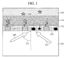
- FIG. 1 is a diagram showing the outline of a nucleic acid analysis device
- FIG. 2 is a diagram showing a first modified example of the nucleic acid analysis device
- FIG. 3 is a diagram showing a second modified example of the nucleic acid analysis device
- FIG. 4 is a diagram showing the outline of a method for analyzing a nucleic acid
- FIG. 5 is a diagram showing a modified example of the nucleic acid analysis device
- FIG. 6 is a diagram showing a third modified example of the nucleic acid analysis device
- FIG. 7 is a diagram showing the outline of a nucleic acid analyzer
- FIG. 8 is a diagram showing the outline of a stepwise elongation reaction
- FIG. 9A is a diagram showing the outline of a noise removal device.
- FIG. 9B is a diagram showing the outline of a fluorescence detector.
- a fluorescence analyzer has: a substrate provided with a probe capable of interacting with a target substance; an excitation light irradiation optical system for irradiating the target substance or the probe with excitation light; a fluorescence detection optical system for detecting fluorescence generated by the irradiation with the excitation light; and a noise removing optical system for irradiating the substrate with noise removing light capable of decomposing the target substance and a foreign particle, which are non-specifically stuck to the surface of the substrate, under a condition that an evanescent field is generated on the surface of the substrate.
- the probe is present outside the evanescent field.
- the excitation light irradiation optical system irradiates the substrate with the excitation light in order that an evanescent field is generated on the surface of the substrate.
- a penetration depth of the evanescent field generated by the irradiation with the excitation light is longer than a penetration depth of the evanescent field generated by the irradiation with the noise removing light.
- the excitation light is visible light
- the noise removing light is ultraviolet light
- a spacer is present on the surface of the substrate and provided with the probe.
- a support body is provided with the probe and faces the surface of the substrate.
- the noise removing optical system irradiates the substrate with the noise removing light such that the noise removing light is totally reflected by an interface between the substrate and a solution and an evanescent field is generated on the surface of the substrate.
- the substrate has a nano-aperture
- the noise removing optical system irradiates the nano-aperture with the noise removing light such that an evanescent field is generated on the surface of the substrate.
- the probe is any one of a deoxyribonucleic acid, a ribonucleic acid, an aptamer, a gene, a nucleosome, a chromatin, a chromosome, a nucleoid, a cell membrane, a cell wall, a virus, an antigen, an antibody, a lectin, a hapten, a receptor, an enzyme, a peptide, a glycosphingolipid and a sphingolipid.
- the target substance is any one of a deoxyribonucleic acid, a ribonucleic acid, an adapter, an antigen, an antibody, a deoxyribonucleoside triphosphate, and a ribonucleoside triphosphate.
- the target substance is a monomer of a fluorescent-labeled nucleotide or an oligomer of a fluorescent-labeled nucleotide
- the probe is a nucleic acid synthesis enzyme or a nucleic acid molecule.
- the probe interacts with the target substance to generate a nucleic acid chain containing the nucleotide, and fluorescence emitted by a fluorescent dye contained in the nucleotide is detected to acquire information on a nucleic acid sequence.
- the noise removing optical system is capable of irradiating, with the noise removing light, an area that is not irradiated with the excitation light.
- Another fluorescence analyzer includes: an optically transparent substrate having a spacer capable of having a probe; a reaction tank capable of holding, on the surface of the optically transparent substrate, a solution containing a target substance capable of interacting with the probe; a prism that is in direct contact with or in indirect contact with the optically transparent substrate; a light source capable of emitting excitation light that is laser light; and a light source capable of emitting ultraviolet light that is laser light, wherein the excitation light is incident on the prism and totally reflected by the surface of the optically transparent substrate to generate an evanescent field in a region in which the probe is present, and the ultraviolet light is incident on the prism and totally reflected by the surface of the optically transparent substrate to generate an evanescent field in a region in which the probe is not present.
- Another fluorescence analyzer includes: an optically transparent substrate; a support body facing the surface of the optically transparent substrate and capable of having a probe; a reaction tank capable of holding, on the surface of the optically transparent substrate, a solution containing a target substance capable of interacting with the probe; a prism that is in direct contact with or in indirect contact with the optically transparent substrate; a light source capable of emitting excitation light that is laser light; and a light source capable of emitting ultraviolet light that is laser light, wherein the excitation light is incident on the prism and totally reflected by the surface of the optically transparent substrate to generate an evanescent field in a region in which the probe is present, and the ultraviolet light is incident on the prism and totally reflected by the surface of the optically transparent substrate to generate an evanescent field in a region in which the probe is not present.
- Another fluorescence analyzer includes: a spacer capable of having a probe; a substrate having a nano-aperture; a reaction tank capable of holding, on the surface of the optically transparent substrate, a solution containing a target substance capable of interacting with the probe; a light source capable of emitting excitation light that is laser light; and a light source capable of emitting ultraviolet light that is laser light, wherein the nano-aperture is irradiated with the excitation light and an evanescent field is generated in a region in which the probe is present, and the nano-aperture is irradiated with the ultraviolet light and an evanescent field is generated in a region in which the probe is not present.
- Another fluorescence analyzer includes: an optically transparent substrate; a support body facing the surface of the optically transparent substrate and capable of having a probe; a spacer capable of having a probe; a substrate having a nano-aperture; a reaction tank capable of holding, on the surface of the substrate, a solution containing a target substance capable of interacting with the probe; a light source capable of emitting excitation light that is laser light; and a light source capable of emitting ultraviolet light that is laser light, wherein the nano-aperture is irradiated with the excitation light and an evanescent field is generated in a region in which the probe is present, and the nano-aperture is irradiated with the ultraviolet light and an evanescent field is generated in a region in which the probe is not present.
- Another fluorescence analyzer includes: a substrate having a probe capable of interacting with a target substance; a first reaction tank capable of holding a solution on the surface of the substrate; a noise removing optical system for irradiating the substrate provided in the first reaction tank with noise removing light under a condition that an evanescent field is generated on the surface of the substrate; a second reaction tank capable of holding, on the surface of an optically transparent substrate, a solution containing the target substance capable of interacting with the probe; an excitation light irradiation optical system for irradiating the substrate provided in the second reaction tank with excitation light; and a fluorescence detection optical system for detecting fluorescence generated by the irradiation with the excitation light.
- a probe 104 is fixed to a device substrate 101 via a spacer 103 .
- a reaction solution 102 is in contact with the substrate 101 and held by the substrate 101 .
- a fluorescent-labeled, unreacted target substance 106 is included in the reaction solution 102 .
- One or more of target substances is specifically captured by the probe 104 , and another or other target substances is non-specifically attached to the surface of the substrate 101 .
- a target substance 105 is specifically captured by the probe 104 .
- the target substance 105 is irradiated with excitation light 113 to generate fluorescence. Fluorescence is widely used in a labeling method and in a known detection method.
- fluorescence is imaged on a two dimensional charge-coupled device and thereby detected by a certain optical system.
- Noise removing light 109 is incident on an interface 110 between the device substrate 101 and the reaction solution 102 at an incident angle 111 (with respect to a normal to the interface 110 ) larger than the critical angle and then totally reflected to generate an evanescent field 112 on the side of the reaction solution 102 with respect to the interface 110 .
- a foreign particle 108 which is not the target substance and causes noise, is attached to the surface of the device substrate for various reasons in general.
- the foreign particle which is an organic substance, causes noise due to fluorescence or light dispersion in many cases.
- a target substance non-specifically attached to and present on the surface of the device substrate 101 causes noise as described above. It is preferable that only the specifically captured target substance 105 be left and a substance attached to the device substrate be removed. More preferably, effects on the probe 104 and on the unreacted target substance 106 that will react and contribute to generation of a fluorescent signal needs to be suppressed to the minimum level.
- a target substance 107 and a foreign particle 108 are non-specifically attached to the surface of the device substrate 101 .
- the target substance 107 and the foreign particle 108 are decomposed by energy of the noise removing light. Fluorescence derived from these substances are significantly reduced or eliminated.
- a light intensity of the evanescent field generated by the irradiation with the noise removing light can be significantly reduced depending on the distance between the interface 110 (on which the noise removing light 109 is totally reflected) and the probe 104 , the specifically captured target substance 105 and the unreacted target substance 106 floating in the reaction solution 102 are not affected by the noise removing light 109 .
- only fluorescence generated from a predetermined target substance can be analyzed.
- a material substantially transparent to the noise removing light may be used.
- at least one of plastic, inorganic polymer, metal, natural polymer, and ceramic may be used as the device substrate 101 .
- Polyethylene, polystyrene, polycarbonate, polypropylene, polyamide, phenolic resin, epoxy resin, polycarbodiimide resin, polyvinyl chloride, polyvinylidene fluoride, polytetrafluoroethylene, polyimide and acrylic resin may be used as the plastic.
- the inorganic polymer glass, crystal, carbon, silica gel, and graphite may be used.
- metal solid metal at ordinary temperatures, such as gold, platinum, silver, copper, iron, aluminum, and magnet, may be used.
- the natural polymer and ceramic diamond, sapphire, alumina, silica, silicon carbide and boron carbide may be used.
- a material substantially transparent to the excitation light be used for the device substrate 101 .
- the material of the device substrate 101 have a larger refractive index to the noise removing light than that of the reaction solution 102 .
- a synthetic quartz, a crystal, a sapphire, or an optical glass be used as the device substrate 101 .
- UV light exhibits a high capability to decompose a substance that causes noise. There is a low possibility that light having wavelengths in the visual light range damages the probe and the target substance.
- photon energy of ultraviolet light having a wavelength of 200 nm or less is relatively high, and is higher than the bond energy of a carbon-carbon double bond, the bond energy of an oxygen-oxygen double bond, the bond energy of a carbon-hydrogen bond, and the bond energy of an oxygen-hydrogen bond and the like. Therefore, the ultraviolet light having a wavelength of 200 nm or less can break most of covalent bonds existing in an organic substance.
- the photon energy of light having a wavelength of 400 nm or more is lower than the photon energy of the ultraviolet light having a wavelength of 200 nm or less, and is also lower than the bond energy of the carbon-carbon double bond, the bond energy of the oxygen-oxygen double bond, the bond energy of the carbon-hydrogen bond, the bond energy of the oxygen-hydrogen bond, the bond energy of a carbon-carbon bond, the bond energy of a carbon-oxygen bond and the like.
- the carbon-carbon bond and the carbon-oxygen bond are relatively unstable. Therefore, there is a lower possibility that the light having a wavelength of 400 nm or more damages the probe and the target substance.
- the light having a wavelength of 400 nm or more has a small effect on direct decomposition of a substance that causes noise, but is absorbed by the substance causing noise and excites the substance, and is therefore capable of improving reactivity of the substance that causes noise.
- the light having a wavelength of 400 nm or more can indirectly decompose the substance that causes noise. It is preferable that light having high energy, such as a laser beam, be used to more efficiently decompose a substance that causes noise.
- the wavelength of the excitation light 113 , and the method for the irradiation with the excitation light 113 , are not limited as long as the excitation light 113 is capable of exciting a fluorescent body of the target substance.
- An evanescent field 114 is generated by irradiation of the interface 110 with the excitation light 113 under the condition that the excitation light 113 is totally reflected by the interface 110 .
- the evanescent field 114 may be used to excite the fluorescent body.
- the evanescent field 114 can suppress fluorescence generated by the unreacted target substance 106 contained in the reaction solution.
- the unreacted target substance 106 is not limited as long as the unreacted target substance 106 interacts with the probe 104 .
- the unreacted target substance 106 the following substances may be used: a nucleic acid; a protein; a sugar chain; a lipid; a complex of those substances; and a compound composed of molecules of those substances resulting from a chemical reaction or an enzyme reaction.
- a fluorescent-labeled DNA, a fluorescent-labeled RNA, a fluorescent-labeled aptamer, a fluorescent-labeled antigen, a fluorescent-labeled antibody, a fluorescent-labeled deoxyribonucleoside triphosphate (used for DNA synthesis), a fluorescent-labeled ribonucleoside triphosphate (used for RNA synthesis) and the like may be used as the unreacted target substance 106 .
- a fluorescent body used for labeling is not limited as long as the fluorescent body is an atom group that emits fluorescence.
- the probe 104 is not limited as long as the probe 104 interacts with the unreacted target substance 106 .
- a nucleic acid, a protein, a sugar chain, a lipid and a complex of those substances may be used. More specifically, the following may be used as the probe 104 : a DNA, an RNA, an aptamer, a gene, a nucleosome, a chromatin, a chromosome, a nucleoid, a cell membrane, a cell wall, a virus, an antigen, an antibody, a lectin, a hapten, a receptor, an enzyme, a peptide, a sphingolipid and a glycosphingolipid.
- the probe 104 be a single strand template DNA (to be analyzed), or a complex of the single strand template DNA and oligonucleotide having a complementary sequence, or a complex of the single strand template DNA, the oligonucleotide having a complementary sequence and DNA synthetase.
- FRET fluorescence resonance energy transfer
- the probe 104 used in a nucleic acid analyzer be capable of specifically recognizing and capturing a nucleic acid to be measured.
- a DNA and an enzyme may be used as the probe 104 used in the nucleic acid analyzer.
- an RNA having a poly(A) sequence can be captured by the probe 104 .
- the nucleic acid can be synthesized on the probe 104 .
- a substrate incorporated in the synthesized nucleic acid during the synthesis is labeled with a fluorescent body and detected. Based on the detection, the sequence of the nucleic acid can be analyzed.
- the shape and material of the spacer 103 is not limited as long as the spacer 103 maintains a distance between the surface of the device substrate 101 and the probe 104 and a distance between the surface of the device substrate 101 and the captured target substance 105 .
- Metal, resin, optical glass, quartz and the like may be used for the material of the spacer 103 .
- a support body 203 that is not located on the surface of the substrate may be used, and the probe 104 may be fixed to the support body 203 , to maintain the distance between the surface of the device substrate 101 and the probe 104 and the distance between the surface of the device substrate 101 and the captured target substance 105 .
- the spacer 103 may be provided for the single probe 104 as shown in FIG. 1 .
- the spacer 103 may be provided for a plurality of probes 104 .
- a unified spacer 103 may be provided for all probes 104 .
- a unified spacer probe 304 may be provided.
- the spacer probe 304 is not limited as long as the spacer probe 304 has a function for maintaining a distance between the device substrate 101 and the captured target substance 105 and a function for interacting with the target substance 105 .
- the spacer probe 304 is a DNA having two chains that serve a spacer function and one chain that serves a probe function (located at an end portion of the spacer probe 304 ).
- a metal structure be used as the spacer probe 304 . In this case, when the target substance 105 has a SH group, the spacer probe 304 can be easily fixed.
- the spacer 103 may have a sandwich structure or a metal structure made of an appropriate material and having an appropriate shape such as a quadrangular pyramid.
- fluorescent enhancement due to localized surface plasmon generated from the structure can be used to reduce background noise derived from fluorescence emitted by the unreacted target substance 106 present in the reaction solution 102 .
- the metal structure can be formed by the following method. That is, a thin film is formed by deposition, sputtering, or deposition and sputtering through a mask, and dry etching or wet etching is then performed on the formed thin film.
- metal, an insulating material and metal may be continuously deposited and/or subjected to sputtering to form a film, and etching or the like may be performed on the formed film to obtain a desired shape, in order to form the metal structure.
- metal, an insulating material and metal may be laminated by deposition and/or sputtering through a mask in order to form the metal structure.
- the following method may be performed to form the metal structure. That is, a metal foil is sandwiched between insulating materials and bonded with the insulating materials. Then, a smooth substrate is bonded with the laminated structure (the metal foil and the insulating materials). The resultant structure is etched to form a desired laminated metal body.
- An appropriate size of the metal structure varies depending on the wavelength of light used for irradiation.
- a resonant frequency suitable for generation of the surface plasmon depends on the interaction of the light with a group of free electrons present on the surface of the metal structure.
- the width and height of the metal structure are preferably in a range of approximately 30 nm to 1000 nm.
- the width and height of the metal structure are not limited to the above range.
- Metal used for the metal structure preferably has a large negative permittivity since a large depolarization field (which is an electric field having a phase opposite to that of an electric field generated by the light) generated in the metal due to the electric field generated by the light leads to a strong localized surface plasmon.
- noble metal such as gold, silver and platinum be used as the metal of the metal structure.
- the distance between the device substrate 101 and the probe 104 be large since effects of the noise removing light on the probe 104 and on the target substance 105 captured by the probe 104 are small when the distance is large.
- the evanescent field 114 reduces the intensity of the excitation light 113 . It is therefore required to balance the excitation light 113 and the evanescent field 114 .
- the distance between the device substrate 101 and the probe 104 be smaller than the penetration depth of the evanescent field 114 generated by the irradiation with the excitation light 113 and larger than the penetration depth of the evanescent field 112 generated by the irradiation with the noise removing light 109 .
- the penetration depths of the evanescent fields 112 and 114 respectively generated by the irradiation with the two types of light 109 and 113 are determined by the wavelengths of the two types of light 109 and 113 , refractive indexes (with respect to the two wavelengths of the light 109 and 113 ) of the two materials between which the interface is present, and incident angles of the two types of light 109 and 113 (with respect to the normal to the interface).
- those conditions (the material of the device substrate 101 , the distance (defined by the spacer 103 ) between the device substrate 101 and the probe 104 , a solvent of the reaction solution 102 , the wavelength and incident angle of the noise removing light 109 , and the wavelength and incident angle of the excitation light 113 ) be determined based on the interrelationships between those conditions.
- refractive indexes of synthetic quartz with respect to light having a wavelength of 193 nm and light having a wavelength of 532 nm are 1.56 and 1.46, respectively.
- refractive indexes of water with respect to the light having the wavelength of 193 nm and the light having the wavelength of 532 nm are 1.44 and 1.33, respectively. It is assumed that the interface between the synthetic quartz and the water is irradiated with the light from the side of the synthetic quartz.
- the light having the wavelength of 193 nm is incident as the noise removing light 109 on the interface between the synthetic quartz and the water at an incident angle (larger than the critical angle) of 75 degrees with respect to a normal to the interface between the synthetic quartz and the water, the penetration depth of the evanescent field 112 generated on the side of the solution (water) with respect to the interface by the incidence of the noise removing light on the interface is 34.3 nm.
- the intensity of the evanescent field 112 present at a location distant by 100 nm from the surface of the device substrate 101 is approximately 5.4 percent of the intensity of the evanescent field 112 on the surface of the device substrate 101 .
- the penetration depth of the evanescent field 114 generated on the side of the solution (water) with respect to the interface by the incidence of the excitation light 113 on the interface is 1019 nm.
- the intensity of the evanescent field 114 present at the location distant by 100 nm from the surface of the device substrate 101 is approximately 91 percent of the intensity of the evanescent field 114 on the surface of the device substrate 101 .
- the intensity of the evanescent field 112 at the location distant by 100 nm from the surface of the device substrate 101 is significantly different from the intensity of the evanescent field 114 at the location distant by 100 nm from the surface of the device substrate 101 as described above. Therefore, it is possible to decompose a causative substance (the target substance 107 and the foreign particle 108 ) that is non-specifically attached to the surface of the device substrate 101 and causes noise, suppress effects of the noise removing light on the probe 104 and the target substance 105 captured by the probe 104 to the minimum level, and obtain a sufficient intensity of fluorescence derived from the target substance 105 captured by the probe 104 .
- a causative substance the target substance 107 and the foreign particle 108
- the target substance 105 When the target substance 105 is composed of a single molecule or a small number (two to several tens) of molecules, it is important to suppress the effects of the noise removing light on the probe 104 and the target substance 105 captured by the probe 104 . This results from the following fact. That is, when the target substance 105 is composed of a large number of molecules, decomposition of the probe 104 and the target substance 105 (captured by the probe 104 ) due to the effects of the noise removing light only reduces the intensity of fluorescence derived from the target substance 105 .
- the irradiation with the noise removing light 109 may be performed under the condition that the reaction solution 102 is removed and a space located on and above the device substrate 101 is filled with a medium 402 not containing a fluorescent dye.
- the medium 402 may have different refractive indexes to the noise removing light 109 and to the excitation light 113 from those of the reaction solution 102 .
- the degree of freedom of combination of the refractive indexes, wavelengths and incident angles can be increased.
- the medium 402 may be a gas such as air or a liquid such as water. A refractive index of air is smaller than that of water.
- the critical angle with respect to the noise removing light 109 can be reduced. Therefore, the noise removing light 109 can be incident on the interface between the device substrate 101 and the medium 402 at a smaller incident angle.
- the noise removing light 109 is incident at the same incident angle as that in the above case on the interface between the device substrate 101 and the medium 402 having a higher refractive index than that of the air, the penetration depth of an evanescent field generated by the incidence of the noise removing light 109 on the interface can be reduced.
- the irradiation with the noise removing light 109 on the surface of the device substrate 101 may be performed before the unreacted target substance 106 and the reaction solution 102 are introduced.
- a causative substance that causes noise is attached to and present on the surface of the device substrate 101 in a manufacturing process, a transfer process, a process of fixing the probe 104 and the like.
- the causative substance that causes noise can be decomposed by the evanescent field 112 generated by the irradiation with the noise removing light. In this case, it is possible to accomplish the object of the present invention without damaging the probe 104 according to the present embodiment.
- noise for the fluorescence analysis can be reduced by decomposing and removing a substance that causes noise.
- the medium 402 different from the reaction solution 102 used for the fluorescence detection may be used.
- irradiation with the noise removing light After the irradiation with the noise removing light is performed before the unreacted target substance 106 and the reaction solution 102 are introduced and before the probe 104 is fixed to the device substrate 101 via the spacer 103 , irradiation with the noise removing light after the reaction solution 102 and the unreacted target substance 106 are introduced may be performed, as shown in FIGS. 1 and 3 .
- the timing for the irradiation with the noise removing light may be the same as the timing for the irradiation with the excitation light for detection of fluorescence. Alternatively, the irradiation with the excitation light may be performed after the irradiation with the noise removing light.
- the analyzer can be simplified, and the throughput of the analyzer can be improved.
- the irradiation with the excitation light is performed after the irradiation with the noise removing light, a large number of device substrates 101 are simultaneously irradiated with the noise removing light, and subjected to fluorescence detection one by one before the irradiation with the excitation light.
- the throughput can be improved, compared with the case where the device substrates 101 are irradiated with the noise removing light one by one.
- FIG. 6 shows a method for generating an evanescent field 612 through nano-apertures 614 by irradiation of noise removing light 609 .
- a thin light shielding film 613 is provided on the surface of the device substrate 101 on the side of the reaction solution 102 .
- the thin light shielding film 613 shields the noise removing light 609 .
- the nano-apertures 614 are provided in the thin light shielding film 613 .
- the diameter of each of the nano-apertures 614 is smaller than the wavelength of the noise removing light 609 .
- Each of the nano-apertures 614 is filled with a transparent medium 615 .
- the transparent medium 615 is substantially transparent with respect to the noise removing light 609 .
- a material of the transparent medium 615 may be the same as that of the reaction solution 102 or that of the device substrate 101 . It is preferable that quartz, sapphire, optical glass and the like be used as the material of the transparent medium 615 .
- the nano-apertures 614 are formed in the following process. First, aluminum is deposited on the surface of the device substrate 101 to form the thin light shielding film 613 having a thickness of 200 nm. Silver, gold, chrome, silicon carbide and the like may be used to form the thin light shielding film 613 as a substance other than aluminum. The plurality of nano-apertures 614 are formed in the thin light shielding film 613 at an interval of 1 ⁇ m by using an electron beam lithography technique. The diameter of each of the nano-apertures 614 is 50 nm. The nano-apertures 614 may extend through the thin light shielding film 613 .
- each of the nano-apertures 614 may be formed such that a portion of the thin light shielding film 613 , which is located at the bottom of the nano-aperture 614 , remains on the surface of the device substrate 101 .
- a method disclosed in “J. Appl. Phys. 2008, Vol. 103, 034301” may be used to form the nano-apertures 614 .
- nucleic acid analyzer which is suitable for use of the method for removing noise according to the first embodiment, is described with reference to FIGS. 7 to 8F . Points different from the first embodiment are mainly described below.
- the nucleic acid analyzer has: a section for supplying, to a nucleic acid analysis device, a nucleic acid sample, nucleic acid synthetase and nucleotide containing a fluorescent dye; a section for irradiating the nucleic acid analysis device with light; a light detector for measuring fluorescence emitted by a fluorescent dye incorporated in a nucleic acid chain due to a nucleic acid elongation reaction occurring due to coexistence of the nucleotide, the nucleic acid synthetase and the nucleic acid sample in the nucleic acid analysis device.
- reference numeral 705 denotes the nucleic acid analysis device according to the second embodiment.
- a metal structure having a height of 100 nm is arranged as the spacer 103 on the surface of the device substrate 101 made of synthetic quartz (made by SHIGUMA KOKI CO., LTD., and having a refractive index of 1.561 to ultraviolet light having a wavelength of 193 nm and a refractive index of 1.45 to 1.48 to light having a wavelength of 350 to 700 nm).
- a biotin-avidin-biotin-labeled single strand template DNA complex is formed as the probe 104 and fixed to the spacer 103 .
- the formation of the complex serving as the probe 104 and the method for fixing the probe 104 to the spacer 103 are described later.
- the nucleic acid analysis device 705 is provided in a reaction chamber.
- the reaction chamber is constituted by a cover plate 701 , a detection window 702 , a flow path 703 and an outlet 704 .
- the flow path 703 and the outlet 704 serve to exchange a solution.
- Polydimethylsiloxane (PDMS) is used as a material of the cover plate 701 and a material of the detection window 702 .
- the thickness of the detection window 702 is 0.17 mm.
- a ⁇ /4 plate 711 circularly polarizes only the laser beam 709 .
- the laser beams 709 and 710 are then incident on the nucleic acid analysis device 705 at an incident angle (larger than the critical angle) with respect to a normal to the surface of the device 705 .
- an evanescent field is generated on the surface of the device 705 by irradiation with the laser beams emitted by the YAG laser light sources 707 and 708 .
- a fluorescent body of a target substance captured by a probe DNA (coupled with the surface of the device 705 ) is present in the evanescent field derived from the irradiation with the laser beams emitted by the YAG laser light sources 707 and 708 .
- the fluorescent body is excited by the laser beams 709 and 710 .
- Part of fluorescence emitted from the fluorescent body is output from the detection window 702 .
- the fluorescence output from the detection window 702 is converted into a parallel pencil by an objective lens 715 (having magnification of 60 times, NA of 1.35, and operating distance of 0.15 mm).
- An optical filter 716 blocks background light and excitation light. Light that passes the optical filter 716 is imaged on a two-dimensional CCD camera 718 by an imaging lens 717 .
- a noise removing optical system is provided in the apparatus according to the second embodiment as a noise removing light irradiation unit.
- the noise removing optical system is constituted by the prism 714 , and optical parts 721 , 723 to 725 as shown in FIG. 7 .
- the optical part 721 is an ArF excimer laser 721 that is an ultraviolet laser light source.
- the ArF excimer laser 721 (that emits laser light having a wavelength of 193 nm and delivers output power of 30 mV) emits ultraviolet laser light 722 for noise removal.
- the optical part 724 is a lens 724 that collects the ultraviolet laser light 722 . After the lens 724 collects the ultraviolet laser light 722 , the ultraviolet laser light 722 is incident on the prism 714 .
- the optical part 725 is an N 2 purge area that includes an optical system for the ultraviolet laser light.
- a nitrogen gas is present in the N 2 purge area 725 to remove oxygen that absorbs ultraviolet light from the optical system.
- an Ar gas may be introduced in the N 2 purge area 725 .
- the N 2 purge area 725 may be in a vacuum state.
- an optical fiber that is made of quartz and has high ultraviolet light transparency or the like may be used as the N 2 purge area 725 .
- the layout of the nucleic acid analyzer is simple since the degree of freedom of the optical path is increased.
- a general optical system arrangement capable of generating an evanescent field may be used.
- the layout is not limited as long as the irradiation with the laser light is performed under the condition that the laser light is totally reflected by the interface between the surface of the device 705 and the solution. For example, it is not necessary that the parts 707 , 708 , and 711 to 714 face each other.
- the parts 707 , 708 , and 711 to 714 may be arranged side by side. Alternatively, the surface of each of the parts 707 , 708 , and 711 to 714 may be perpendicular to the surface of the other one of the parts 707 , 708 , and 711 to 714 .
- An optical system capable of generating an evanescent field through a nano-aperture may be arranged in the nucleic acid analyzer according to the second embodiment.
- an evanescent field is generated on the surface of the device 705 by the irradiation with the ultraviolet laser light.
- a causative substance that causes noise and is located on the surface of the device 705 is present in the evanescent field derived from the ultraviolet laser light.
- the probe DNA (provided on the spacer coupled with the surface of the device 705 ) and the fluorescent body of the target substance (captured by the probe DNA) are present outside the evanescent field derived from the ultraviolet laser light.
- the causative substance that causes noise can be decomposed by the ultraviolet laser light and the noise is removed, while the probe DNA provided on the spacer and the fluorescent body of the target substance captured by the probe DNA are protected. Therefore, fluorescence can be detected with a high signal-to-noise ratio.
- a process of a stepwise elongation reaction is described below with reference to FIGS. 8A to 8F .
- the reaction process is performed according to Non-Patent Documents 1 and 2.
- a buffer containing streptavidin 801 is introduced into a reaction tank 706 through the flow path 703 .
- the streptavidin 801 is combined with biotin 811 present on the metal structure 810 of the device 705 to form a biotin-avidin complex (shown in FIG. 8A ).
- a primer 803 is hybridized with a single strand template DNA 802 , which is a target modified by biotin.
- the template DNA-primer complex of a single molecule is fixed through the combination of the biotin and the avidin (shown in FIG. 8B ). After the fixation reaction, an excess template DNA-primer complex and excess biotin are rinsed off with a flushing buffer.
- a Thermo Sequenase reaction buffer (containing Termo Sequenase polymerase 806 and a dATP ( 3 ′-O-allyl-dATP-PC-R6G) 805 in which a 3′ end labeled with a fluorescent body R6G is modified with an allyl group) is introduced into the reaction tank 706 through the flow path 703 .
- An elongation reaction is then performed.
- the dATP 805 is incorporated in the template DNA-primer complex by the polymerase elongation reaction.
- the 3′ end of the dATP 805 is modified with the allyl group, one or more bases are not incorporated in the template DNA-primer complex.
- the unreacted dATP 805 and the polymerase 806 are rinsed off with a flushing buffer from the reaction tank 706 .
- a chip is irradiated with the laser light 709 emitted by the YAG laser light source 707 and fluorescence is detected ( FIG. 8D ). In this case, it is determined based on the presence of fluorescence at a predetermined location whether or not the dATP is incorporated in the template DNA-primer complex. Then, the chip is irradiated with the laser light 710 emitted by the YAG laser light source 708 . A fluorescent body 807 , with which the dATP 805 incorporated in the complex is labeled, is removed by photocleavage ( FIG. 8E ). Then, a solution 808 containing palladium is introduced in the reaction tank 706 .
- the allyl group present at the 3′ end of the dATP incorporated in the complex is replaced with a hydroxyl group by a palladium-catalyzed reaction ( FIG. 8F ).
- the elongation reaction of the template DNA-primer complex can be carried out again since the allyl group present at the 3′ end is replaced with the hydroxyl group.
- the reaction tank 706 is cleaned with a flushing buffer. The process from a step shown in FIG. 8C to the cleaning is repeatedly performed on each dNTP in the order of ademine (A), cytosine (C), guanine (G), and thymine (T) to determine the sequence of the fixed single strand template DNA 802 .
- the analyzer according to the present embodiment is capable of measuring fluorescence on a plurality of the metal structures 810 simultaneously.
- the analyzer is therefore capable of simultaneously determining the types of dNTPs incorporated in template DNA-primer complexes different from each other, i.e., the sequences of template DNAs.
- the device according to the present embodiment it is possible to reduce noise derived from the target substance 107 non-specifically stuck onto a device substrate 809 . According to the present embodiment, a large number of target substances can be detected at one time with high contrast.
- a member other than the device 705 may be irradiated with the noise removing light by means of the noise removing optical system according to the present embodiment.
- the flow path 703 and the tank (that stores a solution such as a buffer necessary for a reaction) may be irradiated with the noise removing light. This makes it possible to remove noise caused by a substance contained in a buffer or the like.
- a substance that causes noise and floats in the solution cannot be removed.
- the irradiation on the flow path 703 or on the tank makes it possible to remove the substance that causes noise and floats in the solution.
- a solution that does not contain a substance e.g., the unreacted target substance 106 and the template DNA
- a substance e.g., the unreacted target substance 106 and the template DNA
- FIGS. 9A and 9B Another example of a desired configuration of the nucleic acid analyzer will be described with reference to FIGS. 9A and 9B . Points different from the first and second embodiments will be mainly described.
- the nucleic acid analyzer according to the third embodiment of the present invention has a noise removal device (shown in FIG. 9A ) and a fluorescence detector (shown in FIG. 9B ).
- a noise removal device shown in FIG. 9A
- a fluorescence detector shown in FIG. 9B
- the device 705 is provided in a noise removal chamber.
- the noise removal chamber is capable of storing a solution containing a target substance on the side of a low refractive index layer.
- the noise removal chamber has a cover plate 901 , an inlet 903 and an outlet 904 .
- the inlet 903 and the outlet 904 serve to exchange a solution.
- Parts 721 , 723 to 725 provided in the noise removal device, which are shown in FIG. 9A are substantially the same as the parts 721 , 723 to 725 , which are shown in FIG. 7 .
- Ultraviolet laser light 722 shown in FIG.
- the configuration of the fluorescence detector shown in FIG. 9B is the same as that of a fluorescence analyzer shown in FIG. 7 .
- the fluorescence analyzer shown in FIG. 7 is constituted by parts (other than the noise removing optical system) of the nucleic acid analyzer shown in FIG. 7 .
- the noise removal device has a chamber
- the fluorescence detector has a chamber
- the chambers and the device 705 may be unified. This means the chamber provided in the noise removal device and the chamber provided in the fluorescence detector are unified.
- the noise removing optical system and the fluorescence detector are separated from each other. Therefore, it is possible to simultaneously perform irradiation with the noise removing light and detection of fluorescence.
- the irradiation with the noise removing light and the detection of fluorescence be repeatedly performed in this order for the number of the devices 705 .
- a time required for the detection of fluorescence is longer than a time required for the irradiation with the noise removing light.
- the noise removal device holds a plurality of the devices 705 , a plurality of the device substrates 101 can be simultaneously irradiated with the noise removing light, and then subjected to fluorescence detection one by one.
- the throughput can be improved, compared with the case where the device substrates 101 are irradiated with the noise removing light one by one.
- a medium having a refractive index different from that of the medium present in the reaction tank 706 may be present in the reaction tank 906 .
Landscapes
- Health & Medical Sciences (AREA)
- Physics & Mathematics (AREA)
- Immunology (AREA)
- General Physics & Mathematics (AREA)
- Pathology (AREA)
- General Health & Medical Sciences (AREA)
- Life Sciences & Earth Sciences (AREA)
- Chemical & Material Sciences (AREA)
- Analytical Chemistry (AREA)
- Biochemistry (AREA)
- Nuclear Medicine, Radiotherapy & Molecular Imaging (AREA)
- Mathematical Physics (AREA)
- Theoretical Computer Science (AREA)
- Engineering & Computer Science (AREA)
- Spectroscopy & Molecular Physics (AREA)
- Investigating, Analyzing Materials By Fluorescence Or Luminescence (AREA)
- Investigating Or Analysing Materials By The Use Of Chemical Reactions (AREA)
- Optical Measuring Cells (AREA)
- Investigating Or Analysing Materials By Optical Means (AREA)
Applications Claiming Priority (2)
| Application Number | Priority Date | Filing Date | Title |
|---|---|---|---|
| JP2008089174A JP4586081B2 (ja) | 2008-03-31 | 2008-03-31 | 蛍光分析装置 |
| JP2008-089174 | 2008-03-31 |
Publications (2)
| Publication Number | Publication Date |
|---|---|
| US20090242804A1 US20090242804A1 (en) | 2009-10-01 |
| US8294122B2 true US8294122B2 (en) | 2012-10-23 |
Family
ID=41115687
Family Applications (1)
| Application Number | Title | Priority Date | Filing Date |
|---|---|---|---|
| US12/400,321 Active 2031-02-21 US8294122B2 (en) | 2008-03-31 | 2009-03-09 | Method for fluorescence analysis and fluorescence analyzer |
Country Status (2)
| Country | Link |
|---|---|
| US (1) | US8294122B2 (ja) |
| JP (1) | JP4586081B2 (ja) |
Families Citing this family (2)
| Publication number | Priority date | Publication date | Assignee | Title |
|---|---|---|---|---|
| JP5497587B2 (ja) * | 2010-03-23 | 2014-05-21 | 株式会社日立ハイテクノロジーズ | マイクロ流路チップ及びマイクロアレイチップ |
| CN105424625A (zh) * | 2015-11-16 | 2016-03-23 | 西北大学 | 一种定量检测糖鞘脂中糖链结构的方法 |
Citations (8)
| Publication number | Priority date | Publication date | Assignee | Title |
|---|---|---|---|---|
| US20030048453A1 (en) * | 2001-09-12 | 2003-03-13 | Fuji Photo Film Co., Ltd. | Sensor utilizing attenuated total reflection |
| US20030224370A1 (en) * | 2002-05-31 | 2003-12-04 | William Rassman | Method and apparatus for recognizing molecular compounds |
| US20060072113A1 (en) * | 2002-12-25 | 2006-04-06 | Boaz Ran | Surface plasmon resonance sensor |
| JP2006153639A (ja) | 2004-11-29 | 2006-06-15 | Sony Corp | ノイズ蛍光処理方法及び蛍光検出システム |
| US7329492B2 (en) | 2000-07-07 | 2008-02-12 | Visigen Biotechnologies, Inc. | Methods for real-time single molecule sequence determination |
| US20090141376A1 (en) * | 2007-02-26 | 2009-06-04 | Smith Lloyd M | Surface plasmon resonance compatible carbon thin films |
| US20090168061A1 (en) * | 2007-12-27 | 2009-07-02 | Takanobu Haga | Fluorescence detection apparatus |
| US20090245604A1 (en) * | 2008-03-31 | 2009-10-01 | Hitachi High-Technologies Corporation | Nucleic acid analyzing apparatus |
Family Cites Families (4)
| Publication number | Priority date | Publication date | Assignee | Title |
|---|---|---|---|---|
| FR2860872A1 (fr) * | 2003-10-09 | 2005-04-15 | Commissariat Energie Atomique | Micro-capteurs et nano-capteurs d'especes chimiques et biologiques a plasmons de surface |
| JP2006177725A (ja) * | 2004-12-21 | 2006-07-06 | Sony Corp | 物質間の相互作用検出部と該検出部を用いるバイオアッセイ用基板、装置及び方法 |
| JP2007017432A (ja) * | 2005-06-08 | 2007-01-25 | Canon Inc | プラズモン共鳴を利用して検体中の標的物質を検知するための検知装置に用いられる検知素子及びその製造方法 |
| JP2008051512A (ja) * | 2006-08-22 | 2008-03-06 | Fujifilm Corp | 近接場光を用いたセンサおよびその作製方法 |
-
2008
- 2008-03-31 JP JP2008089174A patent/JP4586081B2/ja active Active
-
2009
- 2009-03-09 US US12/400,321 patent/US8294122B2/en active Active
Patent Citations (8)
| Publication number | Priority date | Publication date | Assignee | Title |
|---|---|---|---|---|
| US7329492B2 (en) | 2000-07-07 | 2008-02-12 | Visigen Biotechnologies, Inc. | Methods for real-time single molecule sequence determination |
| US20030048453A1 (en) * | 2001-09-12 | 2003-03-13 | Fuji Photo Film Co., Ltd. | Sensor utilizing attenuated total reflection |
| US20030224370A1 (en) * | 2002-05-31 | 2003-12-04 | William Rassman | Method and apparatus for recognizing molecular compounds |
| US20060072113A1 (en) * | 2002-12-25 | 2006-04-06 | Boaz Ran | Surface plasmon resonance sensor |
| JP2006153639A (ja) | 2004-11-29 | 2006-06-15 | Sony Corp | ノイズ蛍光処理方法及び蛍光検出システム |
| US20090141376A1 (en) * | 2007-02-26 | 2009-06-04 | Smith Lloyd M | Surface plasmon resonance compatible carbon thin films |
| US20090168061A1 (en) * | 2007-12-27 | 2009-07-02 | Takanobu Haga | Fluorescence detection apparatus |
| US20090245604A1 (en) * | 2008-03-31 | 2009-10-01 | Hitachi High-Technologies Corporation | Nucleic acid analyzing apparatus |
Non-Patent Citations (7)
| Title |
|---|
| "Optical Cleaning," Optical Application Technology, Material Encyclopedia, Chapter 2, Section 1, p. 8, Sangyo Gijutsu Service Center. |
| Axelrod, Daniel et al., "Total Internal Reflection Fluorescence Microscopy Interactive Java Tutorials Evanescent Field Penetration Depth," (online) Olympus America Inc., retrieve Feb. 24, 2009. . |
| Axelrod, Daniel et al., "Total Internal Reflection Fluorescence Microscopy Interactive Java Tutorials Evanescent Field Penetration Depth," (online) Olympus America Inc., retrieve Feb. 24, 2009. <URL:http://www.olympusmicro.com/primer/java/tirf/penetration/index.html>. |
| Braslavsky, Ido et al., "Sequence information can be obtained from single DNA molecules," PNAS 2003, vol. 100, No. 7, pp. 3960-3964. |
| Foquet, Mathieu et al., "Improved fabrication of zero-mode waveguides for single-molecule detection," Journal of Applied Physics 2008, vol. 103, 034301. |
| Ruparel, Hameer et al., "Design and synthesis of a 3′-O-allyl photocleavable fluorescent nucleotide as a reversible terminator for DNA sequencing by synthesis," PNAS 2005, vol. 102, No. 17, pp. 5932-5937. |
| Ruparel, Hameer et al., "Design and synthesis of a 3'-O-allyl photocleavable fluorescent nucleotide as a reversible terminator for DNA sequencing by synthesis," PNAS 2005, vol. 102, No. 17, pp. 5932-5937. |
Also Published As
| Publication number | Publication date |
|---|---|
| JP2009244000A (ja) | 2009-10-22 |
| JP4586081B2 (ja) | 2010-11-24 |
| US20090242804A1 (en) | 2009-10-01 |
Similar Documents
| Publication | Publication Date | Title |
|---|---|---|
| JP4597175B2 (ja) | 標的物質を検出するための分析装置、又は分析方法、若しくはこれら分析装置及び分析方法に用いるデバイス | |
| GB2558169B (en) | Flow cell for nucleic acid analysis and nucleic acid analyzer | |
| JP5260339B2 (ja) | 核酸分析デバイス、及び核酸分析装置 | |
| JP5432186B2 (ja) | 蛍光検出装置 | |
| EP2292727B1 (en) | Single molecule real time sequencer, nucleic acid analyzer and single molecule real time sequencing method | |
| US20060186346A1 (en) | Method and system for reading microarrays | |
| WO2014034275A1 (ja) | 核酸分析装置 | |
| JP2007333497A (ja) | 蛍光検出デバイスおよび装置 | |
| US20110081655A1 (en) | Nucleic acid analyzing device and nucleic acid analyzer | |
| US8294122B2 (en) | Method for fluorescence analysis and fluorescence analyzer | |
| WO2010137543A1 (ja) | 核酸分析用デバイス、核酸分析装置、及び核酸分析方法 | |
| WO2010089829A1 (ja) | 全反射顕微鏡装置、及び蛍光試料分析方法 | |
| JP2010203900A (ja) | 表面プラズモン増強蛍光センサおよび表面プラズモン増強蛍光センサに用いられるチップ構造体 | |
| JP4121762B2 (ja) | 蛍光検出用支持体 | |
| WO2011074373A1 (ja) | 表面プラズモン増強蛍光測定装置及びチップ構造体 | |
| JPWO2012008258A1 (ja) | 蛍光検出装置およびこれを用いた蛍光検出方法 | |
| JP5026359B2 (ja) | 核酸分析デバイス、核酸分析装置及び核酸分析方法 | |
| JP2011128060A (ja) | プラズモン励起センサ、並びにこれを用いた核酸検出装置および核酸検出方法 | |
| JP5462548B2 (ja) | 核酸分析素子及びそれを用いた核酸分析装置 | |
| JP5433308B2 (ja) | 計測装置、及び計測方法 | |
| JP5690121B2 (ja) | 核酸分析デバイス及びそれを用いた核酸分析システム | |
| JP2010243454A (ja) | 核酸分析デバイス、及び核酸分析装置 | |
| US20040135996A1 (en) | Biosensor with an arbitrary substrate that can be characterised in photothermal deflection | |
| JP2014122916A (ja) | 表面プラズモン増強蛍光センサおよび表面プラズモン増強蛍光センサに用いられるチップ構造体ユニット |
Legal Events
| Date | Code | Title | Description |
|---|---|---|---|
| AS | Assignment |
Owner name: HITACHI HIGH-TECHNOLOGIES CORPORATION, JAPAN Free format text: ASSIGNMENT OF ASSIGNORS INTEREST;ASSIGNORS:OBARA, TAKAYUKI;TAKAHASHI, SATOSHI;MAEKAWA, AKIRA;AND OTHERS;REEL/FRAME:022365/0692;SIGNING DATES FROM 20081104 TO 20081107 Owner name: HITACHI HIGH-TECHNOLOGIES CORPORATION, JAPAN Free format text: ASSIGNMENT OF ASSIGNORS INTEREST;ASSIGNORS:OBARA, TAKAYUKI;TAKAHASHI, SATOSHI;MAEKAWA, AKIRA;AND OTHERS;SIGNING DATES FROM 20081104 TO 20081107;REEL/FRAME:022365/0692 |
|
| STCF | Information on status: patent grant |
Free format text: PATENTED CASE |
|
| FEPP | Fee payment procedure |
Free format text: PAYOR NUMBER ASSIGNED (ORIGINAL EVENT CODE: ASPN); ENTITY STATUS OF PATENT OWNER: LARGE ENTITY |
|
| FPAY | Fee payment |
Year of fee payment: 4 |
|
| AS | Assignment |
Owner name: HITACHI HIGH-TECH CORPORATION, JAPAN Free format text: CHANGE OF NAME AND ADDRESS;ASSIGNOR:HITACHI HIGH-TECHNOLOGIES CORPORATION;REEL/FRAME:052259/0227 Effective date: 20200212 |
|
| MAFP | Maintenance fee payment |
Free format text: PAYMENT OF MAINTENANCE FEE, 8TH YEAR, LARGE ENTITY (ORIGINAL EVENT CODE: M1552); ENTITY STATUS OF PATENT OWNER: LARGE ENTITY Year of fee payment: 8 |
|
| MAFP | Maintenance fee payment |
Free format text: PAYMENT OF MAINTENANCE FEE, 12TH YEAR, LARGE ENTITY (ORIGINAL EVENT CODE: M1553); ENTITY STATUS OF PATENT OWNER: LARGE ENTITY Year of fee payment: 12 |