US8225693B2 - Control lever mechanism adapted to be mounted to a cowl of a materials handling vehicle - Google Patents
Control lever mechanism adapted to be mounted to a cowl of a materials handling vehicle Download PDFInfo
- Publication number
- US8225693B2 US8225693B2 US11/689,085 US68908507A US8225693B2 US 8225693 B2 US8225693 B2 US 8225693B2 US 68908507 A US68908507 A US 68908507A US 8225693 B2 US8225693 B2 US 8225693B2
- Authority
- US
- United States
- Prior art keywords
- control lever
- section
- lever
- plane
- set out
- Prior art date
- Legal status (The legal status is an assumption and is not a legal conclusion. Google has not performed a legal analysis and makes no representation as to the accuracy of the status listed.)
- Active, expires
Links
- 230000007246 mechanism Effects 0.000 title claims abstract description 69
- 238000005007 materials handling Methods 0.000 title claims abstract description 18
- 230000007935 neutral effect Effects 0.000 claims description 4
- 239000002184 metal Substances 0.000 claims description 3
- 239000007787 solid Substances 0.000 claims description 2
- 208000031481 Pathologic Constriction Diseases 0.000 claims 1
- 239000000463 material Substances 0.000 description 9
- 238000003754 machining Methods 0.000 description 8
- 229910000831 Steel Inorganic materials 0.000 description 4
- 239000010959 steel Substances 0.000 description 4
- 238000003466 welding Methods 0.000 description 4
- 238000005452 bending Methods 0.000 description 3
- 238000005266 casting Methods 0.000 description 3
- 230000004048 modification Effects 0.000 description 2
- 238000012986 modification Methods 0.000 description 2
- 230000002411 adverse Effects 0.000 description 1
- 230000008901 benefit Effects 0.000 description 1
- 230000008859 change Effects 0.000 description 1
- 230000008878 coupling Effects 0.000 description 1
- 238000010168 coupling process Methods 0.000 description 1
- 238000005859 coupling reaction Methods 0.000 description 1
- 230000000694 effects Effects 0.000 description 1
Images


Classifications
-
- B—PERFORMING OPERATIONS; TRANSPORTING
- B66—HOISTING; LIFTING; HAULING
- B66F—HOISTING, LIFTING, HAULING OR PUSHING, NOT OTHERWISE PROVIDED FOR, e.g. DEVICES WHICH APPLY A LIFTING OR PUSHING FORCE DIRECTLY TO THE SURFACE OF A LOAD
- B66F9/00—Devices for lifting or lowering bulky or heavy goods for loading or unloading purposes
- B66F9/06—Devices for lifting or lowering bulky or heavy goods for loading or unloading purposes movable, with their loads, on wheels or the like, e.g. fork-lift trucks
- B66F9/075—Constructional features or details
- B66F9/20—Means for actuating or controlling masts, platforms, or forks
-
- E—FIXED CONSTRUCTIONS
- E02—HYDRAULIC ENGINEERING; FOUNDATIONS; SOIL SHIFTING
- E02F—DREDGING; SOIL-SHIFTING
- E02F9/00—Component parts of dredgers or soil-shifting machines, not restricted to one of the kinds covered by groups E02F3/00 - E02F7/00
- E02F9/20—Drives; Control devices
- E02F9/2004—Control mechanisms, e.g. control levers
-
- G—PHYSICS
- G05—CONTROLLING; REGULATING
- G05G—CONTROL DEVICES OR SYSTEMS INSOFAR AS CHARACTERISED BY MECHANICAL FEATURES ONLY
- G05G1/00—Controlling members, e.g. knobs or handles; Assemblies or arrangements thereof; Indicating position of controlling members
- G05G1/04—Controlling members for hand actuation by pivoting movement, e.g. levers
-
- Y—GENERAL TAGGING OF NEW TECHNOLOGICAL DEVELOPMENTS; GENERAL TAGGING OF CROSS-SECTIONAL TECHNOLOGIES SPANNING OVER SEVERAL SECTIONS OF THE IPC; TECHNICAL SUBJECTS COVERED BY FORMER USPC CROSS-REFERENCE ART COLLECTIONS [XRACs] AND DIGESTS
- Y10—TECHNICAL SUBJECTS COVERED BY FORMER USPC
- Y10T—TECHNICAL SUBJECTS COVERED BY FORMER US CLASSIFICATION
- Y10T74/00—Machine element or mechanism
- Y10T74/20—Control lever and linkage systems
- Y10T74/20576—Elements
- Y10T74/20582—Levers
- Y10T74/20612—Hand
Definitions
- the control lever mechanism includes a plurality of control levers, each of which is formed from a tube material and bent by a bending apparatus at appropriate locations to provide a desired lever shape.
- the tube material bending operations are costly to effect.
- the diameter of the tube material near an end location, i.e., where a knob is attached, is typically reduced. This reducing operation is also costly.
- the levers made from the tube material are typically mounted to the vehicle cowl using castings which are bolted to the levers. Because the cowl mounted levers are long, any mounting errors between the bolted-on castings and the levers will adversely change the spacing between the knobs at the opposite ends of the levers.
- control lever mechanism adapted to be mounted to a cowl of a materials handling vehicle is desired.
- an improved control lever mechanism adapted to be mounted to a cowl of a materials handling vehicle.
- the mechanism includes control levers configured so as to maximize a view zone of an operator.
- the control levers may be mounted using bosses welded to the levers.
- a pin passes through bores in the bosses as well as bores in a bracket so as to mount the control levers to the vehicle cowl.
- bolted on castings may not be employed for mounting the control levers to the vehicle cowl.
- the control levers may be laser cut from a metal sheet. Hence, costly bending operations for forming bends in tube material are avoided.
- a control lever mechanism for being mounted to a cowl of a main body of a materials handling vehicle.
- the control lever mechanism may comprise at least one lever structure including a control lever having a section which falls within or is approximately parallel with a lowermost view plane of a view zone of an operator, wherein the operator view zone includes at least one view plane positioned above the lowermost view plane, and apparatus for mounting the lever structure to the main body cowl.
- the control lever may have first, second, third and fourth sections.
- the third section may define the section which falls within or is approximately parallel with the lowermost view plane.
- the first and second sections may meet to define a first obtuse angle
- the second and third sections may meet to define a second obtuse angle
- the third and fourth sections may meet to define a third obtuse angle
- the second, third and fourth sections may have approximately a U-shape.
- the fourth section may include an operator gripping portion.
- a first side surface of the control lever may be positioned in a first plane and a second side surface of the control lever may be positioned in a second plane which is generally parallel to the first plane.
- the lever structure may further comprise a support element coupled to an end of the control lever.
- the support element may have a face positioned in a plane that is angled to a plane containing a side surface of the lever.
- the support element may comprise a boss coupled to the control lever.
- the control lever end may include a bore. The boss may extend at least part way through the bore and may be welded to the control lever end.
- the lever assembly may further comprise an extension element coupled to the control lever end.
- the extension element may be coupled to a valve linkage and have a side wall parallel to the face of the support element.
- the support element may include a bore and the apparatus for mounting the lever structure to the main body cowl may comprise a bracket coupled to the main body cowl and a pin extending through the bore in the support element and holes or bores in the bracket.
- the at least one lever structure may comprise first and second lever structures.
- the first lever structure may include a first control lever having a section which falls within or is approximately parallel with the lowermost view plane and the second lever structure may include a second control lever having a section which falls within or is approximately parallel with the lowermost view plane.
- the first lever structure may further comprise a first support element coupled to an end of the first control lever.
- the first support element may have a first face positioned at a first angle to a plane containing a side surface of the first lever.
- the second lever structure may further comprise a second support element coupled to an end of the second control lever.
- the second support element may comprise a second face positioned at a second angle to a plane containing a side surface of the second lever. The second angle may be greater than the first angle.
- Each of the first and second control levers may have first, second, third and fourth sections.
- the third section may define the section which falls within or is approximately parallel with the lowermost view plane.
- the fourth section of the second control lever may have a length that is greater than a length of the fourth section of the first control lever.
- the first and second control levers may be laser cut from a solid, generally planar sheet of metal.
- a control lever mechanism for being mounted to a cowl of a main body of a materials handling vehicle.
- the control lever mechanism may comprise at least one lever structure including a control lever having first, second, third and fourth sections.
- the second, third and fourth sections may have approximately a U-shape.
- the fourth section may include an operator gripping portion.
- the control lever mechanism may further include apparatus for mounting the lever structure to the main body cowl.
- the lever structure may further comprise a support element coupled to an end of the control lever having a face positioned in a plane that is angled to a plane containing a side surface of the control lever.
- a control lever mechanism adapted to be mounted to a cowl of a main body of a materials handling vehicle.
- the control lever mechanism may comprise at least one lever structure including a control lever and a support element coupled to an end of the control lever.
- the support element may have a face positioned in a plane that is angled to a plane containing a side surface of the control lever.
- the control lever mechanism may further include apparatus for mounting the lever structure to the main body cowl.
- the support element may comprise a boss coupled to the control lever.
- the control lever end may include a bore and the boss may extend at least part way through the bore and be welded to the lever end.
- the lever assembly may further comprise an extension element coupled to the control lever end and be adapted to be coupled to a valve linkage.
- the extension element may have a side wall parallel to the face of the support element.
- the at least one lever structure may comprise first and second lever structures having first and second control levers, respectively.
- the first lever structure may further comprise a first support element coupled to an end of the first control lever.
- the first support element may have a first face positioned at a first angle to a plane containing a side surface of the first lever.
- the second lever structure may further comprise a second support element coupled to an end of the second control lever.
- the second support element may have a second face positioned at a second angle to a plane containing a side surface of the second lever. The second angle may be greater than the first angle.
- FIG. 1 is a side view of a materials handling vehicle including a control lever mechanism constructed in accordance with the present invention
- FIG. 1A is a perspective view of the control lever mechanism
- FIG. 1B is a perspective view of control levers of the control lever mechanism illustrated in FIGS. 1 and 1A and other control levers that have first and second sections extending at 90 degrees to one another;
- FIG. 2 is a perspective view of the control lever mechanism and valve apparatus of the vehicle illustrated in FIG. 1 ;
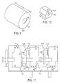
- FIG. 3 is an exploded view of the control lever mechanism and valve apparatus illustrated in FIG. 2 ;
- FIG. 4 is a side view of the control lever mechanism
- FIG. 5 is a side view of first sections of control levers and a bracket to which the control levers are mounted, wherein one control lever section is shown in phantom;
- FIG. 6 is a side view of the first control lever
- FIG. 7 is a view of the first control lever, wherein the first control lever has been rotated from its position illustrated in FIG. 6 ;
- FIG. 8 is an enlarged view of an end of a first section of the first control lever
- FIG. 9 is a perspective view of a boss to be inserted into a bore provided in the end of the first section of the first control lever and welded to the first control lever;
- FIG. 10 is a perspective view of a first extension element to be welded to the end of the first section of the first control lever;
- FIG. 11 is a view of first, second and third microswitches of the valve apparatus of the vehicle illustrated in FIG. 1 ;
- FIG. 12 is a side view of the first section of the first control lever and a corresponding boss and extension;
- FIG. 13 is a view of the first section of the first control lever and the corresponding boss and extension rotated from the position illustrated in FIG. 12 ;
- FIG. 14 is a view taken along view line 14 - 14 in FIG. 13 ;
- FIG. 15 is a side view of the first section of the second control lever and a corresponding boss and extension
- FIG. 16 is a view of the first section of the second control lever and the corresponding boss and extension rotated from the position illustrated in FIG. 15 ;
- FIG. 17 is a view taken along view line 17 - 17 in FIG. 16 ;
- FIG. 18 is a side view of the first section of a third control lever and a corresponding boss and extension;
- FIG. 19 is a view of the first section of the third control lever and the corresponding boss and extension rotated from the position illustrated in FIG. 18 ;
- FIG. 20 is a view taken along view line 20 - 20 in FIG. 19 ;
- FIG. 21 is a side view of the first section of a fourth control lever and a corresponding boss and extension;
- FIG. 22 is a view of the first section of the fourth control lever and the corresponding boss and extension rotated from the position illustrated in FIG. 21 ;
- FIG. 23 is a view taken along view line 23 - 23 in FIG. 22 .
- FIG. 1 illustrates a materials handling vehicle comprising a fork lift truck 10 .
- the truck 10 comprises a main body or frame 20 having a cowl 30 located forward of an operator's compartment 40 and near an A-post 22 of the main body 20 , i.e., the cowl 30 is the front portion of the main body 20 located forward of the operator's compartment 40 and adjacent the A-post 22 .
- the truck 10 further includes four wheels 50 (only two of which are illustrated in FIG. 1 ). At least one wheel 50 is driven and at least one wheel 50 is steerable.
- the operator's compartment 40 comprises a seat 42 for receiving an operator O. Extending into the operator's compartment is a steering wheel 52 for effecting steering of the steerable wheel(s).
- first, second, third and fourth control levers 60 - 63 are also extending into the operator's compartment 40 .
- the control lever mechanism 70 is mounted to the cowl 30 of the main body 20 .
- the control lever mechanism 70 is also coupled to a valve apparatus 72 , see FIGS. 2 and 3 .
- a pair of forks 100 are mounted on a fork carriage mechanism 110 that includes a fork carriage 112 and a load backrest 114 .
- the forks 100 are coupled to the fork carriage 112 which, in turn, is coupled to an extensible mast assembly 120 .
- the load backrest 114 is coupled to the fork carriage 112 .
- the mast assembly 120 includes a pivotable mast member 122 that does not move vertically and first and second nested mast members 124 and 126 , which are coupled to and capable of vertical movement relative to the mast member 122 .
- the mast member 122 is pivotably coupled to the main body 20 , while the fork carriage 112 is coupled to the second movable mast member 126 .
- the mast assembly 120 includes a plurality of hydraulic cylinders (not shown) for effecting vertical movement of the mast members 124 and 126 . Further, hydraulic piston/cylinder units 128 (only one is shown in FIG. 1 ) are coupled to the main body 20 and the mast member 122 for tilting mast members 122 , 124 and 126 toward and away from the truck 10 about a substantially horizontal axis.
- a first auxiliary device (not shown) is provided between the mast assembly 120 and the carriage mechanism 110 for moving the carriage mechanism 110 and the forks 100 from side to side, i.e., in and out of the paper in FIG. 1
- a second auxiliary device (not shown) is provided which may perform a function such as varying the distance between the forks, i.e., either moving the forks closer together or further apart.
- the illustrated control lever mechanism 70 includes first, second, third and fourth lever structures 200 , 210 , 220 and 230 , respectively.
- the first lever structure 200 comprises the first control lever 60 .
- the first lever 60 is preferably laser cut from a planar steel plate and has first, second, third and fourth sections, 60 A- 60 D, respectively, see FIGS. 3 and 4 .
- the first and second sections 60 A and 60 B meet to define a first obtuse angle ⁇ 1
- the second and third sections 60 B and 60 C meet to define a second obtuse angle ⁇ 2
- the third and fourth sections 60 C and 60 D meet to define a third obtuse angle ⁇ 3 .
- the second, third and fourth sections 60 B- 60 D of the first control lever 60 have approximately a U-shape, see FIGS. 3 , 4 and 6 .
- a first knob 160 D formed from a polymeric material may be molded onto the fourth section 60 D and defines a gripping portion for the fourth section 60 D, see FIG. 3 .
- a first side surface 60 E of the control lever 60 may be positioned in a first plane P 1 and a second side surface 60 F of the control lever 60 may be positioned in a second plane P 2 which is generally parallel to the first plane P 1 , see FIG. 7 .
- a bore 260 A is provided in an end 260 of the first section 60 A of the first control lever 60 , see FIGS. 6 and 8 .
- a support element comprising a generally cylindrical boss 360 is inserted into the bore 260 A and welded to the end 260 , see FIGS. 12-14 .
- the boss 360 may have a length L B1 of about 43 mm, see FIG. 9 .
- the boss 360 is angled within the bore 260 A such that a first outer face 360 A of the boss 360 defines an angle ⁇ 1 of about 6.8 degrees with the first side surface 60 E of the control lever 60 , see FIG. 13 .
- the boss 360 is then welded to the control lever 60 .
- the first outer face 360 A of the boss 360 is machined to ensure that the outer face 360 A is extending at the angle ⁇ 1 of about 6.8 degrees with the first side surface 60 E of the control lever 60 .
- An opposing second outer face 360 C of the boss 360 may also be machined to the angle ⁇ 1 . However, this latter machining operation of the second outer face 360 C may not be necessary.
- a bore 360 B is machined completely through the boss 360 .
- An axis of the bore 360 B extends at an angle of about 90 degrees to the machined first outer face 360 A of the boss 360 .
- the bore 260 A in the end 260 of the first section 60 A of the first control lever 60 is slightly elliptical in shape, i.e., axis D 1 is slightly greater in length than axis D 2 , see FIG. 8 , so as to accommodate the angularly oriented boss 360 .
- an outermost point 360 D on the boss 360 is positioned a distance D B1 of approximately 26.8 mm from the first side surface 60 E of the control lever 60 , see FIG. 13 .
- the end 260 of the first section 60 A of the first control lever 60 includes first, second and third substantially planar faces 260 B, 260 C and 260 D.
- a first extension element 460 is welded to the first face 260 B, see FIGS. 12-14 .
- the extension element 460 is generally hexagonal in shape, see FIG. 10 . Prior to being welded, the first extension element 460 is positioned relative to the first face 260 B such that a first outer face 460 A of the extension element 460 is substantially parallel to the first outer face 360 A of the boss 360 .
- the first outer face 460 A of the extension element 460 is machined to ensure that the first outer face 460 A is substantially parallel to the first outer face 360 A of the boss 360 .
- An opposing second outer face 460 C of the extension element 460 may also be machined so as to be parallel with the first outer face 460 A. However, this latter machining operation of the second outer face 460 C may not be necessary.
- a bore 460 B is machined completely through the extension element 460 .
- An axis of the bore 460 B extends at an angle of about 90 degrees to the machined first outer face 460 A of the extension element 460 .
- the first outer face 360 A of the boss 360 is spaced approximately 14.7 mm from the first outer face 460 A of the extension element 460 .
- the extension element 460 has a length L E of about 18.1 mm, see FIG. 10 .
- the second lever structure 210 comprises the second control lever 61 .
- the second lever 61 is preferably laser cut from a planar steel plate and has first, second, third and fourth sections, 61 A- 61 D, respectively, see FIG. 3 .
- the first and second sections 61 A and 61 B meet to define a first obtuse angle
- the second and third sections 61 B and 61 C meet to define a second obtuse angle
- the third and fourth sections 61 C and 61 D meet to define a third obtuse angle.
- the second, third and fourth sections 61 B- 61 D of the second control lever 61 have approximately a U-shape, see FIG. 3 .
- a second knob 161 D formed from a polymeric material may be molded onto the fourth section 61 D and defines a gripping portion for the fourth section 61 D, see FIG. 3 .
- a first side surface 61 E of the control lever 61 may be positioned in a plane which is generally parallel with a plane in which a second side surface 61 F of the control lever 61 is positioned, see FIG. 16 .
- a bore 261 A is provided in an end 261 of the first section 61 A of the second control lever 61 , see FIGS. 15 and 17 .
- a support element comprising a generally cylindrical boss 361 is inserted into the bore 261 A and welded to the end 261 , see FIGS. 15-17 .
- the boss 361 may have a length L B2 of about 38 mm, see FIG. 16 .
- the boss 361 is angled within the bore 261 A such that a first outer face 361 A of the boss 361 defines an angle ⁇ 2 of about 9.6 degrees with the first side surface 61 E of the control lever 61 , see FIG. 16 .
- the boss 361 is then welded to the control lever 61 .
- the first outer face 361 A of the boss 361 is machined to ensure that the outer face 361 A is extending at the angle ⁇ 2 of about 9.6 degrees with the first side surface 61 E of the control lever 61 .
- An opposing second outer face 361 C of the boss 360 may also be machined to the angle ⁇ 2 . However, this latter machining operation of the second outer face 361 C may not be necessary.
- a bore 361 B is machined through the boss 361 .
- An axis of the bore 361 B extends at an angle of about 90 degrees to the machined first outer face 361 A of the boss 361 .
- the bore 261 A in the end 261 of the first section 61 A of the second control lever 61 is slightly elliptical in shape so as to accommodate the angularly oriented boss 361 .
- an outermost point 361 D on the boss 361 is positioned a distance D B2 of approximately 17 mm from the first side surface 61 E of the control lever 61 .
- the end 261 of the first section 61 A of the second control lever 61 includes first, second and third substantially planar faces 261 B, 261 C and 261 D, see FIG. 17 .
- a second extension element 461 is welded to the first face 261 B, see FIGS. 15-17 .
- the extension element 461 is generally hexagonal in shape. Prior to being welded, the extension element 461 is positioned relative to the first face 261 B such that a first outer face 461 A of the extension element 461 is substantially parallel to the first outer face 361 A of the boss 361 .
- the first outer face 461 A of the extension element 461 is machined to ensure that the first outer face 461 A is substantially parallel to the first outer face 361 A of the boss 361 .
- An opposing second outer face 461 C of the extension element 461 may also be machined so as to be parallel with the first outer face 461 A. However, this latter machining operation of the second outer face 461 C may not be necessary.
- a bore 461 B is machined through the extension element 461 .
- An axis of the bore 461 B extends at an angle of about 90 degrees to the machined first outer face 461 A of the extension element 461 .
- the first outer face 361 A of the boss 361 is spaced approximately 7.8 mm from the first outer face 461 A of the extension element 461 .
- the extension element 461 has a length of about 18.2 mm.
- the third lever structure 220 comprises the third control lever 62 .
- the third control lever 62 is preferably laser cut from a planar steel plate and has first, second, third and fourth sections, 62 A- 62 D, respectively, see FIG. 3 .
- the first and second sections 62 A and 62 B meet to define a first obtuse angle
- the second and third sections 62 B and 62 C meet to define a second obtuse angle
- the third and fourth sections 62 C and 62 D meet to define a third obtuse angle.
- the second, third and fourth sections 62 B- 62 D of the third control lever 62 have approximately a U-shape, see FIG. 3 .
- a third knob 162 D formed from a polymeric material may be molded onto the fourth section 62 D and defines a gripping portion for the fourth section 62 D, see FIG. 3 .
- a first side surface 62 E of the control lever 62 may be positioned in a plane which is generally parallel with a plane in which a second side surface 62 F of the control lever 62 is positioned, see FIG. 19 .
- a bore 262 A is provided in an end 262 of the first section 62 A of the third control lever 62 , see FIGS. 18 and 20 .
- a support element comprising a generally cylindrical boss 362 is inserted into the bore 262 A and welded to the end 262 , see FIGS. 18-20 .
- the boss 362 may have a length L B3 of about 38 mm.
- the boss 362 is angled within the bore 262 A such that a first outer face 362 A of the boss 362 defines an angle ⁇ 3 of about 12.4 degrees with the first side surface 62 E of the control lever 62 , see FIG. 19 .
- the boss 362 is then welded to the control lever 62 .
- the first outer face 362 A of the boss 362 is machined to ensure that the outer face 362 A is extending at the angle ⁇ 3 of about 12.4 degrees with the first side surface 62 E of the control lever 62 .
- An opposing second outer face 362 C of the boss 362 may also be machined to the angle ⁇ 3 . However, this latter machining operation of the second outer face 362 C may not be necessary.
- a bore 362 B is machined through the boss 362 .
- An axis of the bore 362 B extends at an angle of about 90 degrees to the machined first outer face 362 A of the boss 362 .
- the bore 262 A in the end 262 of the first section 62 A of the third control lever 62 is slightly elliptical in shape so as to accommodate the angularly oriented boss 362 .
- an outermost point 362 D on the boss 362 is positioned a distance D B3 of approximately 13 mm from the first side surface 62 E of the control lever 62 .
- the end 262 of the first section 62 A of the third control lever 62 includes first, second and third substantially planar faces 262 B, 262 C and 262 D.
- a third extension element 462 is welded to the first face 262 B, see FIGS. 18-20 .
- the extension element 462 is generally hexagonal in shape. Prior to being welded, the extension element 462 is positioned relative to the first face 262 B such that a first outer face 462 A of the extension element 462 is substantially parallel to the first outer face 362 A of the boss 362 .
- the first outer face 462 A of the extension element 462 is machined to ensure that the first outer face 462 A is substantially parallel to the first outer face 362 A of the boss 362 .
- An opposing second outer face 462 C of the extension element 462 may also be machined so as to be parallel with the first outer face 462 A. However, this latter machining operation of the second outer face 462 C may not be necessary.
- a bore 462 B is machined through the extension element 462 .
- An axis of the bore 462 B extends at an angle of about 90 degrees to the machined first outer face 462 A of the extension element 462 .
- first outer face 362 A of the boss 362 is spaced approximately 5.9 mm from the first outer face 462 A of the extension element 462 .
- the extension element 462 has a length of about 18.2 mm.
- the fourth lever structure 230 comprises the fourth control lever 63 .
- the fourth control lever 63 is preferably laser cut from a planar steel plate and has first, second, third and fourth sections, 63 A- 63 D, respectively, see FIG. 3 .
- the first and second sections 63 A and 63 B meet to define a first obtuse angle
- the second and third sections 63 B and 63 C meet to define a second obtuse angle
- the third and fourth sections 63 C and 63 D meet to define a third obtuse angle.
- the second, third and fourth sections 63 B- 63 D of the fourth control lever 63 have approximately a U-shape, see FIG. 3 .
- a fourth knob 163 D formed from a polymeric material may be molded onto the fourth section 63 D and defines a gripping portion for the fourth section 63 D, see FIG. 3 .
- a first side surface 63 E of the control lever 63 may be positioned in a plane which is generally parallel with a plane in which a second side surface 63 F of the control lever 63 is positioned, see FIG. 22 .
- a bore 263 A is provided in an end 263 of the first section 63 A of the fourth control lever 63 , see FIGS. 21 and 23 .
- a support element comprising a generally cylindrical boss 363 is inserted into the bore 263 A and welded to the end 263 , see FIGS. 21-23 .
- the boss 363 may have a length L B4 of about 42 mm.
- the boss 363 is angled within the bore 263 A such that a first outer face 363 A of the boss 363 defines an angle ⁇ 4 of about 14.8 degrees with the first side surface 63 E of the control lever 63 , see FIG. 22 .
- the boss 363 is then welded to the control lever 63 .
- the first outer face 363 A of the boss 363 is machined to ensure that the outer face 363 A is extending at the angle ⁇ 4 of about 14.8 degrees with the first side surface 63 E of the control lever 63 .
- An opposing second outer face 363 C of the boss 363 may also be machined to the angle ⁇ 4 . However, this latter machining operation of the second outer face 363 C may not be necessary.
- a bore 363 B is machined through the boss 363 .
- An axis of the bore 363 B extends at an angle of about 90 degrees to the machined first outer face 363 A of the boss 363 .
- the bore 263 A in the end 263 of the first section 63 A of the fourth control lever 63 is slightly elliptical in shape so as to accommodate the angularly oriented boss 363 .
- an outermost point 363 D on the boss 363 is positioned a distance D B4 of approximately 10.6 mm from the first side surface 63 E of the control lever 63 .
- the end 263 of the first section 63 A of the fourth control lever 63 includes first, second and third substantially planar faces 263 B, 263 C and 263 D.
- a fourth extension element 463 is welded to the first face 263 B, see FIGS. 21-23 .
- the extension element 463 is generally hexagonal in shape. Prior to being welded, the extension element 463 is positioned relative to the first face 263 B such that a first outer face 463 A of the extension element 463 is substantially parallel to the first outer face 363 A of the boss 363 .
- the first outer face 463 A of the extension element 463 is machined to ensure that the first outer face 463 A is substantially parallel to the first outer face 363 A of the boss 363 .
- An opposing second outer face 463 C of the extension element 463 may also be machined so as to be parallel with the first outer face 463 A. However, this latter machining operation of the second outer face 463 C may not be necessary.
- a bore 463 B is machined through the extension element 463 . An axis of the bore 463 B extends at an angle of about 90 degrees to the machined first outer face 463 A of the extension element 463 .
- the first outer face 363 A of the boss 363 is spaced approximately 3.8 mm from the first outer face 463 A of the extension element 463 .
- the extension element 463 has a length of about 18.4 mm.
- the control lever mechanism 70 further includes apparatus 170 for mounting the first, second, third and fourth lever structures 200 , 210 , 220 and 230 to the cowl 30 of the truck main body 20 .
- the mounting apparatus 170 comprises a bracket 172 and a pin 174 , see FIG. 3 .
- the bracket 172 is coupled to the cowl 30 via bolts 173 A and nuts 173 B, see also FIGS. 2 and 4 .
- Positioned on opposing sides of the bosses 360 - 363 are spring washers 176 , see FIG. 3 .
- Positioned adjacent to a first spring washer 176 A and a final spring washer 176 B are flat washers 178 .
- the pin 174 is extended through the spring washers 176 , the flat washers 178 and the bores 360 B, 361 B, 362 B and 363 B of the bosses 360 - 363 , see FIG. 3 .
- the second lever structure 210 is positioned adjacent to the first lever structure 200
- the third lever structure 220 is positioned adjacent to the second lever structure 210
- the fourth lever structure 230 is positioned adjacent to the third lever structure 220 .
- the pin 174 also passes through bores 172 A in the bracket 172 .
- the pin 174 may be held in the bores 172 A via a friction-fit arrangement or clips (not shown).
- the bosses 360 - 363 are capable of rotating relative to the pin 174 .
- the first, second, third and fourth control levers 60 - 63 are generally aligned when viewed from the side.
- the fourth section 61 D of the second control lever 61 is slightly longer than the fourth section 60 D of the first control lever 60
- the fourth section 62 D of the third control lever 62 is slightly longer than the fourth section 61 D of the second control lever 61
- the fourth section 63 D of the fourth control lever 63 is slightly longer than the fourth section 62 D of the third control lever 62 , see FIG. 1A .
- control lever mechanism 70 is coupled to a valve apparatus 72 , see FIGS. 2 and 3 .
- First, second, third and fourth valve linkages 500 , 502 , 504 and 506 are provided for coupling the first, second, third and fourth lever structures 200 , 210 , 220 , and 230 of the control lever mechanism 70 to first, second, third and fourth spool valves 600 , 602 , 604 and 606 , respectively, forming part of the valve apparatus 72 .
- First ends 500 A, 502 A, 504 A and 506 A of the linkages 500 , 502 , 504 and 506 are coupled via pins 508 and clips 510 to the first, second, third and fourth extensions 460 - 463 of the first, second, third and fourth lever structures 200 , 210 , 220 and 230 .
- Second ends 500 B, 502 B, 504 B and 506 B of the linkages 500 , 502 , 504 and 506 are coupled via pins 512 and clips 514 to first, second, third and fourth valve extensions 600 A, 602 A, 604 A and 606 A of the valves 600 , 602 , 604 and 606 .
- the distance between the first and second ends 500 A and 500 B of the first linkage 500 may be varied via a turnbuckle 500 C; the distance between the first and second ends 502 A and 502 B of the second linkage 502 may be varied via a turnbuckle 502 C; the distance between the first and second ends 504 A and 504 B of the third linkage 504 may be varied via a turnbuckle 504 C; and the distance between the first and second ends 506 A and 506 B of the fourth linkage 506 may be varied via a turnbuckle 506 C.
- the spacing between the first ends 500 A, 502 A, 504 A and 506 A of the linkages 500 , 502 , 504 and 506 is substantially equal to the spacing between the valve extensions 600 A, 602 A, 604 A and 606 A.
- the spacing between the knobs 160 D, 161 D, 162 D and 163 D provided on the fourth sections 60 D, 61 D, 62 D and 63 D of the first, second, third and fourth control levers 60 - 63 is preferably greater than the spacing between the first ends 500 A, 502 A, 504 A and 506 A of the linkages 500 , 502 , 504 and 506 so as to ergonomically enhance the arrangement of the knobs 160 D, 161 D, 162 D and 163 D relative to the operator O.
- the first valve 600 may control the height of the forks 100
- the second valve 602 may control the tilt of the mast assembly 120
- the third valve 604 may control side shift of the carriage mechanism 110 and the forks 100
- the fourth valve 606 may control the distance between the forks 100 .
- the first, second, third and fourth lever structures 200 , 210 , 220 and 230 are rotated clockwise or counter-clockwise, as viewed in FIG. 4 .
- the forks 100 may be lowered and when the first knob 160 D is pulled toward the operator O, the forks 100 may be raised.
- the mast assembly 120 When the second knob 161 D is pushed in a direction away from the operator O, the mast assembly 120 may tilt away from the operator O and when the second knob 161 D is pulled toward the operator O, the mast assembly 120 may tilt toward the operator O.
- the carriage mechanism 110 and forks 100 When the third knob 162 D is pushed in a direction away from the operator O, the carriage mechanism 110 and forks 100 may shift to the left and when the third knob 162 D is pulled in a direction toward the operator, the carriage mechanism 110 and forks 100 may shift to the right.
- the fourth knob 163 D When the fourth knob 163 D is pushed in a direction away from the operator O, the forks may move further apart and when the fourth knob 163 D is pulled in a direction toward the operator, the forks may move closer together.
- the second face 260 C on the end 260 of the first section 60 A of the first lever 60 defines a first stop that engages a center plate 172 B of the bracket 172 so as to prevent an operator O from pushing the first lever 60 too far in a direction away from the operator O and damaging the valve 600 , see FIGS. 3 , 8 and 14 .
- the third face 260 D on the end 260 of the first section 60 A of the first lever 60 defines a second stop that engages the center plate 172 B of the bracket 172 so as to prevent an operator O from pulling the first lever 60 too far in a direction toward the operator O and damaging the valve 600 .
- the second faces 261 C, 262 C and 263 C on the second, third and fourth levers 61 - 63 define first stops that engage the center plate 172 B of the bracket 172 so as to prevent an operator O from pushing those levers 61 - 63 too far in a direction away from the operator O and damaging the valves 602 , 604 and 606 , see FIGS. 3 , 5 , 17 , 20 and 23 .
- the third faces 261 D, 262 D and 263 D on the ends 261 - 263 of the second, third and fourth levers 61 - 63 define second stops that engage the center plate 172 B of the bracket 172 so as to prevent an operator O from pulling the levers 61 - 63 too far in a direction toward the operator O and damaging the valves 602 , 604 and 606 .
- first, second and third microswitches 710 , 712 and 714 are bolted to a bracket 720 , which, in turn, is bolted to the valve apparatus 72 .
- an upper section 500 D of the second end 500 B of the linkage 500 is shown just engaging an actuator arm 710 A of the first microswitch 710
- upper and lower sections 502 D and 502 E, respectively, of the second end 502 B of the linkage 502 are shown just engaging respectively actuator arms 712 A and 714 A of the second and third microswitches 712 and 714 .
- the fork carriage mechanism 110 and the forks 100 may be lowered if the first knob 160 D is pushed in a direction away from the operator O such that the upper section 500 D of the second end 500 B of the linkage 500 moves relative to the actuator arm 710 A so as to actuate the first microswitch 710 .
- the mast assembly 120 may be moved via the hydraulic piston/cylinder units 128 toward the operator O if an operator moves the second knob 161 D beyond its neutral position in a direction toward the operator O such that a lower section 502 E of the second end 502 B of the linkage 502 moves relative to the actuator arm 714 A of the third microswitch 714 so as to actuate that microswitch 714 .
- the second microswitch 712 is actuated causing movement of the hydraulic cylinders for raising and lowering the mast members 124 and 126 relative to the mast member 122 to be disabled, movement of the mast assembly 120 away from the operator to be disabled, and movement of the fork carriage mechanism 110 and the forks 100 to be disabled.
- the microswitch 712 is no longer actuated such that movement of the hydraulic cylinders for raising and lowering the mast members 124 and 126 relative to the mast member 122 may occur, movement of the mast assembly 120 toward the operator may occur, and movement of the fork carriage mechanism 110 and the forks 100 may occur.
- the second microswitch 712 is actuated when an operator moves the second knob 161 D from a neutral position in a direction away from the operator O such that an upper section 502 D of the second end 502 B of the linkage 502 moves relative to the actuator arm 712 A so as to actuate the second microswitch 712 .
- the valve apparatus 72 is coupled to the cowl 30 of the truck main body 20 via bolts 72 A and nuts 72 B, see FIG. 3 .
- each control lever 60 - 63 is configured to maximize a view zone V Z of an operator in seat 42 looking forward in the direction of the forks 100 , see FIG. 1 . More particularly, the shape of the control levers 60 - 63 has been designed so as to minimize blockage by the control levers 60 - 63 of an operator viewing window W defined by a right-side portion 120 A of the mast assembly 120 , as viewed by an operator in seat 42 and looking in the direction of the forks 100 , and the right A-post 22 , see FIG. 1A . Referring again to FIG.
- the operator view zone V Z is defined by a lowermost view plane VP LM and all view planes located above the lowermost view plane VP LM , including a view plane VP 1 .
- the first, second, third and fourth lever structures 200 , 210 , 220 230 are configured such that the third sections 60 C, 61 C, 62 C and 63 C of the control levers 60 - 63 fall within or are approximately parallel with the lowermost view plane VP LM of the operator view zone V Z . It is believed that by configuring the lever structures 200 , 210 , 220 and 230 in this manner, the operator view zone V Z can be maximized.
- control levers 700 - 703 having a different configuration, i.e., first and second sections extending at generally 90 degrees to one another, are shown in phantom in FIG. 1 and in solid line in FIG. 1B , where the levers 700 - 703 extend into the operator view zone V Z .
- the operator view zone V Z would be reduced as the lowermost view plane would no longer comprise view plane VP LM , but instead, would comprise view plane VP LM700 , see FIG. 1 .
- the first, second, third and fourth lever structures 200 , 210 , 220 230 may have a different configuration.
- the first and second sections 60 A and 60 B of the first control lever may be combined into a single section 760 A.
- Section 760 A merges directly into the third section 760 C such that the control lever includes only three sections instead of four.
- the second, third and fourth control levers may have a similar shape.
Landscapes
- Engineering & Computer Science (AREA)
- Structural Engineering (AREA)
- Civil Engineering (AREA)
- Transportation (AREA)
- Mechanical Engineering (AREA)
- Combustion & Propulsion (AREA)
- Life Sciences & Earth Sciences (AREA)
- Geology (AREA)
- Chemical & Material Sciences (AREA)
- Mining & Mineral Resources (AREA)
- General Engineering & Computer Science (AREA)
- Physics & Mathematics (AREA)
- General Physics & Mathematics (AREA)
- Automation & Control Theory (AREA)
- Mechanical Control Devices (AREA)
- Forklifts And Lifting Vehicles (AREA)
Priority Applications (1)
| Application Number | Priority Date | Filing Date | Title |
|---|---|---|---|
| US11/689,085 US8225693B2 (en) | 2006-03-21 | 2007-03-21 | Control lever mechanism adapted to be mounted to a cowl of a materials handling vehicle |
Applications Claiming Priority (2)
| Application Number | Priority Date | Filing Date | Title |
|---|---|---|---|
| US78417606P | 2006-03-21 | 2006-03-21 | |
| US11/689,085 US8225693B2 (en) | 2006-03-21 | 2007-03-21 | Control lever mechanism adapted to be mounted to a cowl of a materials handling vehicle |
Publications (2)
| Publication Number | Publication Date |
|---|---|
| US20070221010A1 US20070221010A1 (en) | 2007-09-27 |
| US8225693B2 true US8225693B2 (en) | 2012-07-24 |
Family
ID=38265559
Family Applications (1)
| Application Number | Title | Priority Date | Filing Date |
|---|---|---|---|
| US11/689,085 Active 2030-03-06 US8225693B2 (en) | 2006-03-21 | 2007-03-21 | Control lever mechanism adapted to be mounted to a cowl of a materials handling vehicle |
Country Status (7)
| Country | Link |
|---|---|
| US (1) | US8225693B2 (fr) |
| EP (1) | EP1999058B1 (fr) |
| CN (1) | CN101405213B (fr) |
| AU (1) | AU2007226830B2 (fr) |
| CA (1) | CA2645872C (fr) |
| RU (1) | RU2450965C2 (fr) |
| WO (1) | WO2007109716A2 (fr) |
Cited By (2)
| Publication number | Priority date | Publication date | Assignee | Title |
|---|---|---|---|---|
| US20160130782A1 (en) * | 2014-11-10 | 2016-05-12 | Caterpillar Inc. | Motor Grader Implement Valve Layout for Narrow Front Cab |
| US20160130783A1 (en) * | 2014-11-10 | 2016-05-12 | Caterpillar Inc. | Motor Grader Implement Valve Layout for Narrow Front Cab |
Families Citing this family (4)
| Publication number | Priority date | Publication date | Assignee | Title |
|---|---|---|---|---|
| JP5162019B1 (ja) * | 2011-10-28 | 2013-03-13 | 株式会社小松製作所 | 操作レバーロック装置 |
| US11046564B2 (en) | 2015-11-09 | 2021-06-29 | Crown Equipment Corporation | Order picker materials handling vehicle with improved downward visibility when driving elevated |
| JP7188298B2 (ja) * | 2019-07-02 | 2022-12-13 | 株式会社豊田自動織機 | 産業車両の操作レバー装置 |
| CA3181503A1 (fr) | 2020-06-05 | 2021-12-09 | Craig Rekow | Systeme de commande d'operateur pour un vehicule de manutention de materiaux |
Citations (28)
| Publication number | Priority date | Publication date | Assignee | Title |
|---|---|---|---|---|
| GB717876A (en) | 1952-05-27 | 1954-11-03 | Yale & Towne Mfg Co | Improvements in or relating to motorized industrial trucks |
| GB866833A (en) | 1958-06-27 | 1961-05-03 | Lansing Bagnall Ltd | Improvements in or relating to control-gear for hydraulic circuits |
| GB1221645A (en) | 1967-06-26 | 1971-02-03 | Lansing Bagnall Ltd | Improvements in or relating to industrial trucks having a hydraulic circuit for performing a load handling operation |
| US3737003A (en) | 1971-05-03 | 1973-06-05 | Caterpillar Tractor Co | Adjustable control console for vehicles |
| US3841698A (en) | 1973-02-26 | 1974-10-15 | Crown Controls Corp | Vehicle with retractable guard |
| US3916717A (en) | 1974-11-15 | 1975-11-04 | Massey Ferguson Inc | Single lever gear shift control |
| US3985394A (en) * | 1975-04-07 | 1976-10-12 | Deere & Company | Tractor-implement control system |
| US4026349A (en) | 1976-03-15 | 1977-05-31 | Schaap Robert E | Cowl for an industrial electric truck |
| US4291896A (en) | 1979-11-02 | 1981-09-29 | Fiat-Allis Construction Machinery, Inc. | Adjustable steering wheel and control lever console |
| US4392669A (en) | 1980-10-24 | 1983-07-12 | Martin Robert P | Cab for lift truck with swing out windshield |
| USRE31646E (en) | 1971-05-03 | 1984-08-14 | Caterpillar Tractor Co. | Adjustable control console for vehicles |
| JPS6241200A (ja) | 1985-08-15 | 1987-02-23 | 小松フオ−クリフト株式会社 | 荷役車両の動力供給装置 |
| US4664221A (en) | 1986-01-21 | 1987-05-12 | Deere & Company | Function control linkage for a vehicle |
| US4664220A (en) | 1986-01-21 | 1987-05-12 | Deere & Company | Method of arranging function controls for a vehicle |
| US4682787A (en) | 1986-01-21 | 1987-07-28 | Deere & Company | Steering unit and control lever console for a vehicle |
| US4706776A (en) | 1985-02-06 | 1987-11-17 | Kabushiki Kaisha Komatsu Seisakusho | Vehicle steering and operating apparatus |
| US4981047A (en) | 1988-12-20 | 1991-01-01 | Kabushiki Kaisha Kobe Seiko Sho | Control unit for a construction machine |
| US5056983A (en) | 1989-04-13 | 1991-10-15 | Kabushiki Kaisha Toyoda Jidoshokki Seisakusho | Load handling control apparatus for a fork lift truck |
| US5056985A (en) | 1989-12-08 | 1991-10-15 | Ford New Holland, Inc. | Backhoe control mechanism |
| US5138756A (en) * | 1989-12-08 | 1992-08-18 | Ford New Holland, Inc. | Method of converting backhoe controls |
| GB2299154A (en) | 1995-03-22 | 1996-09-25 | Still Gmbh | Control arrangement for actuation of control devices through a common control lever |
| JPH09309353A (ja) | 1996-05-23 | 1997-12-02 | Nissan Motor Co Ltd | 産業車両のコントロールレバー装置 |
| US6148688A (en) | 1998-01-09 | 2000-11-21 | Komatsu Est Corporation | Work-machine-lever-support structure for work vehicle |
| US6240802B1 (en) * | 1997-12-18 | 2001-06-05 | Scania Cv Aktiebolag (Publ) | Device for adjusting a two-part gear lever |
| US6257645B1 (en) | 1999-08-24 | 2001-07-10 | Crown Equipment Corporation | Floorboard for a vehicle |
| US6481950B1 (en) | 2000-09-29 | 2002-11-19 | Deere & Company | Control lever assembly |
| JP2003054894A (ja) | 2001-08-10 | 2003-02-26 | Mitsubishi Heavy Ind Ltd | 産業車両の操作レバー装置 |
| US6557586B1 (en) | 1999-08-27 | 2003-05-06 | Crown Equipment Corporation | Control handle support and valve linkage assembly |
Family Cites Families (3)
| Publication number | Priority date | Publication date | Assignee | Title |
|---|---|---|---|---|
| US4646869A (en) * | 1985-07-29 | 1987-03-03 | Dresser Industries, Inc. | Adjustable control console |
| SU1745575A1 (ru) * | 1989-10-25 | 1992-07-07 | Арендное производственное объединение "Днепропетровский комбайновый завод" | Механизм управлени посто нно замкнутой муфтой сцеплени |
| RU26788U1 (ru) * | 2002-09-24 | 2002-12-20 | Общество с ограниченной ответственностью "ИКАР" | Автопогрузчик |
-
2007
- 2007-03-21 AU AU2007226830A patent/AU2007226830B2/en active Active
- 2007-03-21 RU RU2008141456/11A patent/RU2450965C2/ru not_active IP Right Cessation
- 2007-03-21 US US11/689,085 patent/US8225693B2/en active Active
- 2007-03-21 CN CN200780009892.XA patent/CN101405213B/zh active Active
- 2007-03-21 EP EP07758999A patent/EP1999058B1/fr active Active
- 2007-03-21 CA CA2645872A patent/CA2645872C/fr active Active
- 2007-03-21 WO PCT/US2007/064503 patent/WO2007109716A2/fr active Application Filing
Patent Citations (28)
| Publication number | Priority date | Publication date | Assignee | Title |
|---|---|---|---|---|
| GB717876A (en) | 1952-05-27 | 1954-11-03 | Yale & Towne Mfg Co | Improvements in or relating to motorized industrial trucks |
| GB866833A (en) | 1958-06-27 | 1961-05-03 | Lansing Bagnall Ltd | Improvements in or relating to control-gear for hydraulic circuits |
| GB1221645A (en) | 1967-06-26 | 1971-02-03 | Lansing Bagnall Ltd | Improvements in or relating to industrial trucks having a hydraulic circuit for performing a load handling operation |
| USRE31646E (en) | 1971-05-03 | 1984-08-14 | Caterpillar Tractor Co. | Adjustable control console for vehicles |
| US3737003A (en) | 1971-05-03 | 1973-06-05 | Caterpillar Tractor Co | Adjustable control console for vehicles |
| US3841698A (en) | 1973-02-26 | 1974-10-15 | Crown Controls Corp | Vehicle with retractable guard |
| US3916717A (en) | 1974-11-15 | 1975-11-04 | Massey Ferguson Inc | Single lever gear shift control |
| US3985394A (en) * | 1975-04-07 | 1976-10-12 | Deere & Company | Tractor-implement control system |
| US4026349A (en) | 1976-03-15 | 1977-05-31 | Schaap Robert E | Cowl for an industrial electric truck |
| US4291896A (en) | 1979-11-02 | 1981-09-29 | Fiat-Allis Construction Machinery, Inc. | Adjustable steering wheel and control lever console |
| US4392669A (en) | 1980-10-24 | 1983-07-12 | Martin Robert P | Cab for lift truck with swing out windshield |
| US4706776A (en) | 1985-02-06 | 1987-11-17 | Kabushiki Kaisha Komatsu Seisakusho | Vehicle steering and operating apparatus |
| JPS6241200A (ja) | 1985-08-15 | 1987-02-23 | 小松フオ−クリフト株式会社 | 荷役車両の動力供給装置 |
| US4682787A (en) | 1986-01-21 | 1987-07-28 | Deere & Company | Steering unit and control lever console for a vehicle |
| US4664220A (en) | 1986-01-21 | 1987-05-12 | Deere & Company | Method of arranging function controls for a vehicle |
| US4664221A (en) | 1986-01-21 | 1987-05-12 | Deere & Company | Function control linkage for a vehicle |
| US4981047A (en) | 1988-12-20 | 1991-01-01 | Kabushiki Kaisha Kobe Seiko Sho | Control unit for a construction machine |
| US5056983A (en) | 1989-04-13 | 1991-10-15 | Kabushiki Kaisha Toyoda Jidoshokki Seisakusho | Load handling control apparatus for a fork lift truck |
| US5056985A (en) | 1989-12-08 | 1991-10-15 | Ford New Holland, Inc. | Backhoe control mechanism |
| US5138756A (en) * | 1989-12-08 | 1992-08-18 | Ford New Holland, Inc. | Method of converting backhoe controls |
| GB2299154A (en) | 1995-03-22 | 1996-09-25 | Still Gmbh | Control arrangement for actuation of control devices through a common control lever |
| JPH09309353A (ja) | 1996-05-23 | 1997-12-02 | Nissan Motor Co Ltd | 産業車両のコントロールレバー装置 |
| US6240802B1 (en) * | 1997-12-18 | 2001-06-05 | Scania Cv Aktiebolag (Publ) | Device for adjusting a two-part gear lever |
| US6148688A (en) | 1998-01-09 | 2000-11-21 | Komatsu Est Corporation | Work-machine-lever-support structure for work vehicle |
| US6257645B1 (en) | 1999-08-24 | 2001-07-10 | Crown Equipment Corporation | Floorboard for a vehicle |
| US6557586B1 (en) | 1999-08-27 | 2003-05-06 | Crown Equipment Corporation | Control handle support and valve linkage assembly |
| US6481950B1 (en) | 2000-09-29 | 2002-11-19 | Deere & Company | Control lever assembly |
| JP2003054894A (ja) | 2001-08-10 | 2003-02-26 | Mitsubishi Heavy Ind Ltd | 産業車両の操作レバー装置 |
Non-Patent Citations (2)
| Title |
|---|
| Amended claims sent to the European Patent Office for European Patent Application No. 07758999.2. |
| Office Action issued in Russian Application No. 2008141456, based on PCT/US2007/064503; Sep. 15, 2010; Russian Patent Office. |
Cited By (3)
| Publication number | Priority date | Publication date | Assignee | Title |
|---|---|---|---|---|
| US20160130782A1 (en) * | 2014-11-10 | 2016-05-12 | Caterpillar Inc. | Motor Grader Implement Valve Layout for Narrow Front Cab |
| US20160130783A1 (en) * | 2014-11-10 | 2016-05-12 | Caterpillar Inc. | Motor Grader Implement Valve Layout for Narrow Front Cab |
| US9797113B2 (en) * | 2014-11-10 | 2017-10-24 | Caterpillar Inc. | Motor grader implement valve layout for narrow front cab |
Also Published As
| Publication number | Publication date |
|---|---|
| EP1999058A2 (fr) | 2008-12-10 |
| US20070221010A1 (en) | 2007-09-27 |
| WO2007109716A3 (fr) | 2008-01-10 |
| CN101405213B (zh) | 2012-06-20 |
| AU2007226830B2 (en) | 2012-12-13 |
| CA2645872A1 (fr) | 2007-09-27 |
| CN101405213A (zh) | 2009-04-08 |
| RU2450965C2 (ru) | 2012-05-20 |
| WO2007109716A2 (fr) | 2007-09-27 |
| RU2008141456A (ru) | 2010-04-27 |
| AU2007226830A1 (en) | 2007-09-27 |
| CA2645872C (fr) | 2014-12-30 |
| EP1999058B1 (fr) | 2013-03-06 |
Similar Documents
| Publication | Publication Date | Title |
|---|---|---|
| US8225693B2 (en) | Control lever mechanism adapted to be mounted to a cowl of a materials handling vehicle | |
| AU2006246533B2 (en) | Industrial vehicle having working implement | |
| US7780395B2 (en) | Lift arm for skid-steer loader | |
| CA2462969C (fr) | Systeme de commande d'un engin sur roues | |
| US6557658B1 (en) | Forklift having transverse travel system | |
| EP2762642B1 (fr) | Unité de levage pour monteuse chargeuse | |
| EP1947249B1 (fr) | Élément commun de pivot et de support pour une interface de fixation d'un chargeur. | |
| EP3051031B1 (fr) | Chargeuse à roues avec un dispositif de levage | |
| US7699577B2 (en) | Interface plate for mounting a light duty attachment to a lift arm assembly | |
| US20040228715A1 (en) | Folding lift arm assembly for skid steer loader | |
| EP1327602A1 (fr) | Vehicule utilitaire pourvu d'un systeme a deplacement lateral | |
| US20050034913A1 (en) | Interlock control system on wheeled work machine | |
| JP3133793B2 (ja) | リフト・ローダブーム装置およびリフト・ローダブーム装置を用いた作業具移動方法 | |
| EP1997960B1 (fr) | Bras pour chargeur frontal | |
| US20090252588A1 (en) | Lift arm for skid-steer loader | |
| EP1195470B1 (fr) | Machine de terrassement | |
| JP4201122B2 (ja) | リーチ式フォークリフト | |
| EP1264938B1 (fr) | Engin de travaux publics et dispositif d'actionnement du déplacement latéral d'une pelle de chargement | |
| WO1982001362A1 (fr) | Appareil de levage utilisant un parallelogramme | |
| JP3718946B2 (ja) | バッテリ式リーチフォークリフト | |
| JP2000351592A (ja) | 横行システムを持ったフォークリフト | |
| JPH09301694A (ja) | マスト取付型ロードスタビライザ | |
| JP2003171097A (ja) | フォークリフト | |
| JP2003095589A (ja) | 荷役運搬車両 | |
| JPH11222392A (ja) | フォークリフトのサイドシフト装置 |
Legal Events
| Date | Code | Title | Description |
|---|---|---|---|
| AS | Assignment |
Owner name: CROWN EQUIPMENT CORPORATION, OHIO Free format text: ASSIGNMENT OF ASSIGNORS INTEREST;ASSIGNORS:SCHRENK, JULIEN J.;HANSON, ERIC J.;KREMER, JASON R.;SIGNING DATES FROM 20070330 TO 20070413;REEL/FRAME:019355/0117 Owner name: CROWN EQUIPMENT CORPORATION, OHIO Free format text: ASSIGNMENT OF ASSIGNORS INTEREST;ASSIGNORS:SCHRENK, JULIEN J.;HANSON, ERIC J.;KREMER, JASON R.;REEL/FRAME:019355/0117;SIGNING DATES FROM 20070330 TO 20070413 |
|
| STCF | Information on status: patent grant |
Free format text: PATENTED CASE |
|
| CC | Certificate of correction | ||
| FPAY | Fee payment |
Year of fee payment: 4 |
|
| MAFP | Maintenance fee payment |
Free format text: PAYMENT OF MAINTENANCE FEE, 8TH YEAR, LARGE ENTITY (ORIGINAL EVENT CODE: M1552); ENTITY STATUS OF PATENT OWNER: LARGE ENTITY Year of fee payment: 8 |
|
| MAFP | Maintenance fee payment |
Free format text: PAYMENT OF MAINTENANCE FEE, 12TH YEAR, LARGE ENTITY (ORIGINAL EVENT CODE: M1553); ENTITY STATUS OF PATENT OWNER: LARGE ENTITY Year of fee payment: 12 |