US8103470B2 - Method, coupler and apparatus for measuring radiated power - Google Patents
Method, coupler and apparatus for measuring radiated power Download PDFInfo
- Publication number
- US8103470B2 US8103470B2 US12/716,711 US71671110A US8103470B2 US 8103470 B2 US8103470 B2 US 8103470B2 US 71671110 A US71671110 A US 71671110A US 8103470 B2 US8103470 B2 US 8103470B2
- Authority
- US
- United States
- Prior art keywords
- receiving antenna
- under test
- device under
- radiation power
- power
- Prior art date
- Legal status (The legal status is an assumption and is not a legal conclusion. Google has not performed a legal analysis and makes no representation as to the accuracy of the status listed.)
- Expired - Fee Related, expires
Links
- 238000000034 method Methods 0.000 title claims abstract description 126
- 230000005855 radiation Effects 0.000 claims abstract description 449
- 238000012360 testing method Methods 0.000 claims abstract description 341
- 238000005259 measurement Methods 0.000 claims abstract description 231
- 239000002184 metal Substances 0.000 claims abstract description 25
- 238000001228 spectrum Methods 0.000 claims description 62
- 238000004364 calculation method Methods 0.000 claims description 59
- 239000006096 absorbing agent Substances 0.000 claims description 24
- 230000007246 mechanism Effects 0.000 claims description 16
- 230000008569 process Effects 0.000 claims description 16
- 238000003860 storage Methods 0.000 claims description 13
- 238000010183 spectrum analysis Methods 0.000 claims description 8
- 238000000605 extraction Methods 0.000 claims description 7
- 239000000284 extract Substances 0.000 claims description 3
- 238000010586 diagram Methods 0.000 description 21
- 230000002349 favourable effect Effects 0.000 description 21
- 230000005540 biological transmission Effects 0.000 description 11
- 238000004891 communication Methods 0.000 description 9
- 238000012986 modification Methods 0.000 description 8
- 230000004048 modification Effects 0.000 description 8
- 230000010287 polarization Effects 0.000 description 8
- 230000004044 response Effects 0.000 description 8
- 230000035945 sensitivity Effects 0.000 description 7
- 238000013459 approach Methods 0.000 description 5
- 239000004020 conductor Substances 0.000 description 5
- 230000008878 coupling Effects 0.000 description 5
- 238000010168 coupling process Methods 0.000 description 5
- 238000005859 coupling reaction Methods 0.000 description 5
- 238000005388 cross polarization Methods 0.000 description 5
- 238000004088 simulation Methods 0.000 description 5
- 230000008859 change Effects 0.000 description 4
- 229920003002 synthetic resin Polymers 0.000 description 4
- 239000000057 synthetic resin Substances 0.000 description 4
- 238000005520 cutting process Methods 0.000 description 3
- 238000005516 engineering process Methods 0.000 description 3
- 238000012545 processing Methods 0.000 description 3
- 230000008901 benefit Effects 0.000 description 2
- 238000006243 chemical reaction Methods 0.000 description 2
- 230000007423 decrease Effects 0.000 description 2
- 238000009826 distribution Methods 0.000 description 2
- 238000002834 transmittance Methods 0.000 description 2
- 238000010521 absorption reaction Methods 0.000 description 1
- 230000015556 catabolic process Effects 0.000 description 1
- 238000006731 degradation reaction Methods 0.000 description 1
- 238000000151 deposition Methods 0.000 description 1
- 238000001514 detection method Methods 0.000 description 1
- 230000005684 electric field Effects 0.000 description 1
- 230000005672 electromagnetic field Effects 0.000 description 1
- 238000005530 etching Methods 0.000 description 1
- 230000010354 integration Effects 0.000 description 1
- 238000004519 manufacturing process Methods 0.000 description 1
- 239000000463 material Substances 0.000 description 1
- 238000011056 performance test Methods 0.000 description 1
- 239000000523 sample Substances 0.000 description 1
Images


Classifications
-
- G—PHYSICS
- G01—MEASURING; TESTING
- G01R—MEASURING ELECTRIC VARIABLES; MEASURING MAGNETIC VARIABLES
- G01R29/00—Arrangements for measuring or indicating electric quantities not covered by groups G01R19/00 - G01R27/00
- G01R29/08—Measuring electromagnetic field characteristics
- G01R29/0807—Measuring electromagnetic field characteristics characterised by the application
- G01R29/0814—Field measurements related to measuring influence on or from apparatus, components or humans, e.g. in ESD, EMI, EMC, EMP testing, measuring radiation leakage; detecting presence of micro- or radiowave emitters; dosimetry; testing shielding; measurements related to lightning
- G01R29/0821—Field measurements related to measuring influence on or from apparatus, components or humans, e.g. in ESD, EMI, EMC, EMP testing, measuring radiation leakage; detecting presence of micro- or radiowave emitters; dosimetry; testing shielding; measurements related to lightning rooms and test sites therefor, e.g. anechoic chambers, open field sites or TEM cells
-
- H—ELECTRICITY
- H01—ELECTRIC ELEMENTS
- H01Q—ANTENNAS, i.e. RADIO AERIALS
- H01Q19/00—Combinations of primary active antenna elements and units with secondary devices, e.g. with quasi-optical devices, for giving the antenna a desired directional characteristic
- H01Q19/10—Combinations of primary active antenna elements and units with secondary devices, e.g. with quasi-optical devices, for giving the antenna a desired directional characteristic using reflecting surfaces
- H01Q19/12—Combinations of primary active antenna elements and units with secondary devices, e.g. with quasi-optical devices, for giving the antenna a desired directional characteristic using reflecting surfaces wherein the surfaces are concave
- H01Q19/13—Combinations of primary active antenna elements and units with secondary devices, e.g. with quasi-optical devices, for giving the antenna a desired directional characteristic using reflecting surfaces wherein the surfaces are concave the primary radiating source being a single radiating element, e.g. a dipole, a slot, a waveguide termination
-
- H—ELECTRICITY
- H04—ELECTRIC COMMUNICATION TECHNIQUE
- H04B—TRANSMISSION
- H04B17/00—Monitoring; Testing
- H04B17/10—Monitoring; Testing of transmitters
- H04B17/101—Monitoring; Testing of transmitters for measurement of specific parameters of the transmitter or components thereof
- H04B17/102—Power radiated at antenna
Definitions
- the present invention relates to a method for measuring a radiation power, a coupler for measuring a radiation power, and an apparatus for measuring a radiation power. More particularly, the present invention relates to a method for measuring a radiation power, a coupler for measuring a radiation power, and an apparatus for measuring a radiation power, wherein a technology for measuring a radiation power of, for example, a small wireless communication terminal serving as a device under test, with a simple configuration, in a short time, and with high sensitivity is adopted.
- Radiated powers include equivalent isotropically radiation power (EIRP) in any direction and total radiation power (TRP) which is radiated in the entire space.
- EIRP equivalent isotropically radiation power
- TRP total radiation power
- the coupler ( 21 ) for measuring a radiation power configured to be able to support a device under test ( 1 ) which can radiate a radio wave and a receiving antenna ( 15 ) which receives the radio wave radiated from the device under test ( 1 ) in a closed space ( 12 ) enclosed by a metal wall surface ( 11 ), receive by the receiving antenna ( 15 ) the radio wave radiated from the device under test ( 1 ), and output a received signal of the receiving antenna ( 15 ) externally
- the coupler ( 21 ) comprising:
- a power measuring unit ( 60 ) which measures total radiation power of a radio wave radiated from the device under test ( 1 ), from a received signal of the receiving antenna ( 15 ) to be outputted external to the coupler ( 21 ) for measuring a radiation power
- the reflection coefficient measurement module ( 60 a ) sequentially measures a reflection coefficient value S 22 for each of a plurality of measurement frequencies by applying power having the predetermined measurement frequency to the measurement end of the receiving antenna ( 15 ) and measuring power reflected from the receiving antenna ( 15 ) through the measurement end, said plurality of measurement frequencies being predetermined in a predetermined frequency range,
- the apparatus for measuring a radiation power according to the twelfth aspect, wherein the power measuring unit ( 60 ) further comprises:
- a total radiation power value from the device under test 1 can be sequentially calculated for each of the plurality of measurement frequencies.
- FIG. 10 is a diagram illustrated to describe a radio wave absorber ( 70 ) used in a method for measuring a radiation power and an apparatus for measuring a radiation power according to an eighth embodiment of the present invention.
- FIG. 24 is a spectrum waveform diagram illustrated to describe the method for measuring a radiation power according to the third embodiment of the present invention.
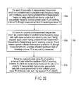
- FIG. 28 is a flowchart of a main part illustrated to describe a method for measuring a radiation power according to a fifth embodiment of the present invention.
- FIG. 19 is a diagram illustrating simulation results to demonstrate that the measurement principle of the method for measuring a radiation power according to the second embodiment of the present invention is right.
- a radio wave radiated from the device under test 1 is a narrow-band signal
- higher-order reflected waves of secondary or higher order waves are made negligible by placing a radio wave absorber inside the closed space 11 of the elliptical mirror 10 or using a receiving antenna with small scattering as the receiving antenna 15 , and in addition a method of comparison, which will be described later, is used from a primary wave, whereby total reflected power of a radio wave radiated from the device under test 1 can be measured accurately.
- FIG. 24 illustrates results of calculation of a total radiation power value Pr from reflection coefficient values S 22 and received powers PL at the measurement frequencies which are set in the above-described manner.
- a spectrum mask of IS-95 which is a standard for mobile phones, for example, used as the device under test 1 is stored and a comparison between the spectrum mask and total radiation power values Pr for a plurality of frequencies is performed to make a pass/fail determination as to whether the total radiation power values Pr satisfy the standard.
- the processes may be performed using a table including measurement frequencies, total radiation powers Pr, and power values corresponding to a spectrum mask.
- step S 43 the value corresponding to the reflection coefficient value S 22 of the receiving antenna 15 which is measured at the above-described step S 42 is compared with a preset threshold value.
- the device under test 1 is disposed to substantially coincide with the position of one focal point F 1 in the closed space 12 of the elliptical sphere 10 , only by an external appearance of the device under test 1 , does not mean the center of radiation of radio waves from the device under test 1 substantially coincides with the position of one focal point F 1 in the closed space 12 of the elliptical sphere 10 .
- a reflection coefficient value S 11 of the device under test 1 itself and an associated reflection coefficient value S 22 of the receiving antenna 15 may degrade, which may result in a position that affects the calculation of a total radiation power value Pr.
- VSWR Voltage Standing Wave Ratio
- a traveling wave voltage and a reflected wave voltage, traveling wave power and reflected wave power, an impedance ratio, etc., which are values corresponding to a reflection coefficient may be used and when they reach favorable values, it may be determined that the position of the device under test 1 is favorable.
- the means for adjusting the position of the device under test 1 is not limited to a mechanism such as that illustrated in FIG. 7 of the aforementioned Patent Document 2 and can be any as long as the mechanism allows to manually adjust the position of the device under test 1 along at least one of XYZ axis lines.
- a mechanism serving as a means for adjusting the position of the device under test 1 which is used in the above-described first exemplary operation of an adjustment to the position of the device under test 1 may further include a mechanism that is driven along at least one of XYZ axis lines and an adjustment to the position of the device under test 1 may be automatically made using a control means.
- a reflection coefficient value S 22 of the receiving antenna is measured to find a position of the device under test 1 in which a favorable reflection coefficient value S 22 of the receiving antenna 15 is obtained.
- the device under test 1 does not need to be moved.
- step S 56 For example, if the return loss is 9 dB then it is determined to be “not favorable”, and if the return loss is 11 dB then it is determined to be “favorable” (step S 56 ).
- step S 56 If it is determined by the determination at step S 56 that the value corresponding to the reflection coefficient value S 22 of the receiving antenna 15 which is measured at step S 55 is not better than the threshold value which is set in advance, then processing returns to step S 54 and the processes at steps S 55 to S 56 are repeated until it is determined by determination at step S 56 that a value corresponding to a reflection coefficient value S 22 of the receiving antenna 15 which is measured at step S 55 is better than the threshold value which is set in advance.
- step S 59 power proportional to a total radiation power value Pr of the device under test 1 is calculated.
- FIG. 4 illustrates a configuration of an apparatus for measuring a radiation power 20 according to a sixth embodiment of the present invention which is based on the method for measuring a radiation power according to the first embodiment.
- the coupler 21 is provided with a wall surface 11 that encloses a closed space 12 of the above-described elliptical mirror 10 ; a device under test supporting member 50 serving as a means for supporting a device under test 1 such that the radiation center position of the device under test 1 is located in the position of one focal point F 1 in the closed space 12 ; and a receiving antenna supporting member 55 serving as a means for supporting a receiving antenna 15 such that the center of the receiving antenna 15 is located in the position of the other focal point F 2 in the closed space 12 .
- the first inner-wall forming body 25 is formed by, for example, performing press work on a metal plate or metal mesh plate that reflects radio waves or depositing a metal film onto an inner wall of a molded article of a synthetic resin.
- the fixtures 57 configured to fix such a receiving antenna 15 fix the receiving antenna 15 with, for example, screws or clips made of a synthetic resin that do not change the characteristics of the receiving antenna 15 , such that the center of reception (radiation) of the antenna element 15 b of the receiving antenna 15 coincides with the focal point F 2 on the supporting plate 56 .
- the gain in the length direction of the antenna element 15 b is very small.
- the length direction of the antenna element 15 b to coincide with a radiation center direction (the direction of the focal point F 1 ) of the device under test 1 , the influence of a direct wave from the device under test 1 to the receiving antenna 15 can be reduced to the smallest possible extent.
- an orientation of the device under test 1 is determined and fixed such that a cross-polarization direction of the device under test 1 coincides with the co-polarization direction of the receiving antenna 15 , and radiation power thereof is measured.
- the receiving antenna 15 when, as the receiving antenna 15 , a loop antenna or two-element orthogonal dipole that can simultaneously receive orthogonal polarization components is adopted, total radiation power of the device under test 1 can be found by a single measurement.
- the coaxial cable 16 passes through a hole made in a lower portion of the flange 26 of the inner-wall forming body 25 , and is pulled out of the coupler 21 and connected to an input end of the power measuring unit 60 .
- the total radiation power calculation module 60 c may be configured such that based on a reflection coefficient value S 22 which is sequentially measured by the reflection coefficient measurement module 60 a for each of the plurality of measurement frequencies which are predetermined in the predetermined frequency range and a value of received power PL which is sequentially measured by the received power measurement module 60 b for each of the plurality of measurement frequencies which are predetermined in the predetermined frequency range, power proportional to a total radiation power value Pr for each of the plurality of measurement frequencies is sequentially calculated by the following equation: PL /(1 ⁇
- FIG. 13 illustrates results of obtaining an output current (impulse response) of the receiving antenna 15 when an impulse is provided to the standard antenna 100 with an element length of 20 mm.
- FIG. 14 illustrates results of obtaining an impulse response which is the same as that described above, for the device under test 1 with an element length of 25 mm.
- a device under test 1 is disposed at one focal point F 1 such that the center of radiation of a radio wave therefrom is positioned at the focal point F 1 , and a radio wave radiated from the device under test 1 is caused to be reflected at the wall surface 11 of the elliptical mirror 10 to allow a receiving antenna 15 disposed at the other focal point F 2 to intensively receive the radio wave, whereby radiation power of the device under test 1 can be measured in accordance with an output signal from the receiving antenna 15 .
- the present invention may be performed using, as the elliptical mirror 10 in accordance with an aspect of the present invention, one having a region obtained by sectioning an elliptical spherical space by a plane formed by an original short-axis line when a plane parallel to a short-axis line of an ellipse illustrated in FIG. 4 is rotated 90 degrees about a long axis, and a plane obtained by rotating the plane 90 degrees, i.e., one having a shape obtained by cutting an elliptical spherical space by one-quarter.
- the elliptical mirror 10 referred to in the present invention may be one having a closed space 12 which has an elliptical spherical shape, a semi-elliptical spherical shape, a quarter-elliptical spherical shape, etc., obtained by rotating an ellipse A illustrated in FIG. 4 by a predetermined angle about at least one of a long-axis line and a short-axis line thereof, and which is enclosed by a wall surface 11 .
Landscapes
- Physics & Mathematics (AREA)
- Electromagnetism (AREA)
- Engineering & Computer Science (AREA)
- Computer Networks & Wireless Communication (AREA)
- Signal Processing (AREA)
- General Physics & Mathematics (AREA)
- Variable-Direction Aerials And Aerial Arrays (AREA)
- Radar Systems Or Details Thereof (AREA)
- Aerials With Secondary Devices (AREA)
- Monitoring And Testing Of Transmission In General (AREA)
Applications Claiming Priority (3)
| Application Number | Priority Date | Filing Date | Title |
|---|---|---|---|
| JP2007-253643 | 2007-09-28 | ||
| JP2007253643 | 2007-09-28 | ||
| PCT/JP2008/067315 WO2009041513A1 (ja) | 2007-09-28 | 2008-09-25 | 放射電力測定方法、放射電力測定用結合器及び放射電力測定装置 |
Related Parent Applications (1)
| Application Number | Title | Priority Date | Filing Date |
|---|---|---|---|
| PCT/JP2008/067315 Continuation WO2009041513A1 (ja) | 2007-09-28 | 2008-09-25 | 放射電力測定方法、放射電力測定用結合器及び放射電力測定装置 |
Publications (2)
| Publication Number | Publication Date |
|---|---|
| US20100153045A1 US20100153045A1 (en) | 2010-06-17 |
| US8103470B2 true US8103470B2 (en) | 2012-01-24 |
Family
ID=40511396
Family Applications (1)
| Application Number | Title | Priority Date | Filing Date |
|---|---|---|---|
| US12/716,711 Expired - Fee Related US8103470B2 (en) | 2007-09-28 | 2010-03-03 | Method, coupler and apparatus for measuring radiated power |
Country Status (5)
| Country | Link |
|---|---|
| US (1) | US8103470B2 (zh) |
| EP (1) | EP2194387B1 (zh) |
| JP (1) | JP5427606B2 (zh) |
| CN (1) | CN101802625B (zh) |
| WO (1) | WO2009041513A1 (zh) |
Cited By (7)
| Publication number | Priority date | Publication date | Assignee | Title |
|---|---|---|---|---|
| US20110032162A1 (en) * | 2009-08-10 | 2011-02-10 | Shenzhen Futaihong Precision Industry Co., Ltd. | Antenna testing device and antenna testing method using the same |
| US20110133999A1 (en) * | 2009-12-04 | 2011-06-09 | Electronics And Telecommunications Research Institute | Apparatus and method for measuring radiated power of terminal |
| US10560203B2 (en) * | 2018-07-06 | 2020-02-11 | Rohde & Schwarz Gmbh & Co. Kg | Measurement system and method for spurious frequency determination |
| DE102018217173A1 (de) * | 2018-10-08 | 2020-04-09 | Fraunhofer-Gesellschaft zur Förderung der angewandten Forschung e.V. | Reflektorsystem in einem radarzielsimulator zum testen einer funktionsfähigkeit eines radarsensors und verfahren zum testen einer funktionsfähigkeit eines radarsensors |
| US10809296B2 (en) | 2017-11-28 | 2020-10-20 | Rohde & Schwarz Gmbh & Co. Kg | Over-the-air test system and method for testing a device under test |
| US11671186B1 (en) | 2022-02-04 | 2023-06-06 | Rohde & Schwarz Gmbh & Co. Kg | Method of determining an equivalent source and over-the-air test system |
| US11698401B1 (en) * | 2022-02-04 | 2023-07-11 | Rohde & Schwarz Gmbh & Co. Kg | Method of simulating an effect of interactions between a device under test and a scattering object and hybrid OTA test system |
Families Citing this family (32)
| Publication number | Priority date | Publication date | Assignee | Title |
|---|---|---|---|---|
| KR20100079644A (ko) * | 2008-12-31 | 2010-07-08 | 충남대학교산학협력단 | 안테나 방사특성 측정방법 |
| JP2010281620A (ja) * | 2009-06-03 | 2010-12-16 | Anritsu Corp | アンテナの放射効率測定方法および装置 |
| JP2011053016A (ja) * | 2009-08-31 | 2011-03-17 | Anritsu Corp | 放射電力測定方法および放射電力測定装置 |
| JP5586256B2 (ja) * | 2010-02-03 | 2014-09-10 | アンリツ株式会社 | 放射電力測定方法および放射電力測定装置 |
| JP5171903B2 (ja) | 2010-08-31 | 2013-03-27 | アンリツ株式会社 | 放射電力測定方法および放射電力測定装置 |
| WO2012048264A2 (en) * | 2010-10-07 | 2012-04-12 | Andrew Llc | Systems and methods of testing active digital radio antennas |
| JP5135410B2 (ja) * | 2010-10-19 | 2013-02-06 | アンリツ株式会社 | Tis測定方法および装置 |
| JP5250058B2 (ja) * | 2011-02-07 | 2013-07-31 | アンリツ株式会社 | 無線端末送受信性能測定方法および装置 |
| JP5551121B2 (ja) * | 2011-07-13 | 2014-07-16 | アンリツ株式会社 | Mimo端末測定方法および測定システム |
| JP5577300B2 (ja) * | 2011-07-14 | 2014-08-20 | アンリツ株式会社 | 無線端末のアンテナ反射損測定方法および測定装置 |
| TWI456215B (zh) * | 2012-01-09 | 2014-10-11 | Wistron Neweb Corp | 無線電子裝置之測試設備 |
| US9843352B2 (en) | 2013-12-26 | 2017-12-12 | Intel Corporation | Method and apparatus for dynamic radio emission compliance monitoring |
| CN106160893B (zh) * | 2015-04-10 | 2019-06-14 | 深圳市通用测试系统有限公司 | 无线终端的测试系统及用于其的控制方法 |
| CN106161703B (zh) * | 2015-04-10 | 2019-11-22 | 深圳市通用测试系统有限公司 | 无线终端的测试系统及用于其的控制方法 |
| EP3182144B1 (en) * | 2015-04-10 | 2019-11-06 | General Test Systems Inc. | Wireless terminal testing system and method for controlling same |
| CN106161704B (zh) * | 2015-04-10 | 2019-07-12 | 深圳市通用测试系统有限公司 | 无线终端的测试系统 |
| CN106291145B (zh) * | 2015-05-12 | 2019-03-01 | 深圳市通用测试系统有限公司 | 无线终端的测试系统 |
| CN106936524B (zh) * | 2015-12-31 | 2023-03-31 | 深圳市通用测试系统有限公司 | 无线终端的测试系统 |
| CN105911369A (zh) * | 2016-06-07 | 2016-08-31 | 乐视控股(北京)有限公司 | 一种天线效率电波暗室测试的快速确认方法 |
| CN106771666A (zh) * | 2016-12-21 | 2017-05-31 | 中国电子科技集团公司第二十研究所 | 一种抗干扰高精度天馈系统多驻波点定位系统 |
| US10677832B2 (en) | 2017-05-26 | 2020-06-09 | Rohde & Schwarz Gmbh & Co. Kg | Over the air measurement system and method |
| US10746773B2 (en) | 2017-05-26 | 2020-08-18 | Rhode & Schwarz Gmbh & Co. Kg | Test system and method for measuring beam characteristics |
| US10677831B2 (en) | 2017-05-26 | 2020-06-09 | Rohde & Schwarz Gmbh & Co. Kg | Test system and method for measuring beam characteristics |
| JP6867346B2 (ja) * | 2017-10-13 | 2021-04-28 | アンリツ株式会社 | アンテナ装置および測定方法 |
| JP7016303B2 (ja) * | 2018-08-08 | 2022-02-04 | 株式会社Nttドコモ | 放射電力推定方法 |
| EP3787112A1 (en) * | 2019-09-02 | 2021-03-03 | Nokia Solutions and Networks Oy | A polarized antenna array |
| US11875659B2 (en) | 2019-12-12 | 2024-01-16 | Google Llc | Privacy-preserving radar-based fall monitoring |
| JP7221243B2 (ja) * | 2020-06-18 | 2023-02-13 | アンリツ株式会社 | 移動端末試験装置、及び移動端末試験方法 |
| US11754676B2 (en) | 2020-08-11 | 2023-09-12 | Google Llc | Precision sleep tracking using a contactless sleep tracking device |
| US11808839B2 (en) | 2020-08-11 | 2023-11-07 | Google Llc | Initializing sleep tracking on a contactless health tracking device |
| US11832961B2 (en) * | 2020-08-11 | 2023-12-05 | Google Llc | Contactless sleep detection and disturbance attribution |
| RU2753829C1 (ru) * | 2020-09-24 | 2021-08-23 | Акционерное общество "Корпорация "Тактическое ракетное вооружение" | Способ определения коэффициента безэховости в радиочастотной безэховой камере и устройство для его осуществления |
Citations (10)
| Publication number | Priority date | Publication date | Assignee | Title |
|---|---|---|---|---|
| JPS63193899A (ja) | 1987-02-06 | 1988-08-11 | 日立精工株式会社 | 鉛筆作図装置における鉛筆芯の残量検出方法 |
| JPH01280399A (ja) | 1988-05-06 | 1989-11-10 | Kajima Corp | 電波無響室 |
| US4931798A (en) * | 1987-06-03 | 1990-06-05 | Tokin Corporation | Electromagnetic anechoic chamber with an inner electromagnetic wave reflection surface and an electromagnetic wave absorption small ball disposed in the chamber |
| JP2000324063A (ja) | 1999-05-11 | 2000-11-24 | Mitsubishi Electric Corp | 無線通信端末評価装置 |
| JP2003318811A (ja) | 2002-04-26 | 2003-11-07 | Nippon Telegr & Teleph Corp <Ntt> | 受信電界強度推定計算装置及び方法並びにプログラム及び記録媒体 |
| JP2003332785A (ja) | 2002-05-14 | 2003-11-21 | Advanced Telecommunication Research Institute International | 電波伝搬用空間 |
| JP2006322921A (ja) | 2005-04-18 | 2006-11-30 | Anritsu Corp | 電磁波シールドボックス |
| JP2007040894A (ja) | 2005-08-04 | 2007-02-15 | Funai Electric Co Ltd | 電磁妨害波測定装置 |
| US7420522B1 (en) * | 2004-09-29 | 2008-09-02 | The United States Of America As Represented By The Secretary Of The Navy | Electromagnetic radiation interface system and method |
| WO2009136638A1 (ja) | 2008-05-09 | 2009-11-12 | アンリツ株式会社 | 放射電力を測定する方法、放射電力の測定用結合器及び放射電力を測定する装置 |
Family Cites Families (9)
| Publication number | Priority date | Publication date | Assignee | Title |
|---|---|---|---|---|
| JP3436669B2 (ja) | 1997-11-04 | 2003-08-11 | 株式会社キャンドックスシステムズ | 電磁波結合装置 |
| JP4526643B2 (ja) * | 2000-03-17 | 2010-08-18 | 三菱電機株式会社 | 放射ノイズ測定データ表示方法、放射ノイズ測定システムおよび放射ノイズ測定用プログラム記憶媒体 |
| JP2002196027A (ja) * | 2000-12-26 | 2002-07-10 | Fukui Prefecture | シールド効果評価器及びシールド効果測定法 |
| JP2002319908A (ja) * | 2001-02-13 | 2002-10-31 | Advantest Corp | 隣接チャネル漏洩電力比測定装置およびチャネル電力測定装置、方法、プログラム、および該プログラムを記録した記録媒体 |
| JP2002344397A (ja) * | 2001-05-21 | 2002-11-29 | Ntt Docomo Inc | 妨害波探索システムおよび妨害波探索方法 |
| CN1639993A (zh) * | 2002-02-22 | 2005-07-13 | 夏普株式会社 | 无线通信系统 |
| JP2003283365A (ja) * | 2002-03-20 | 2003-10-03 | Sharp Corp | 無線通信システム |
| JP2003319447A (ja) * | 2002-04-18 | 2003-11-07 | Denso Corp | 通信施設 |
| CN100412555C (zh) * | 2005-07-08 | 2008-08-20 | 智捷科技股份有限公司 | 天线功率测量方法及其装置 |
-
2008
- 2008-09-25 WO PCT/JP2008/067315 patent/WO2009041513A1/ja active Application Filing
- 2008-09-25 EP EP08834119.3A patent/EP2194387B1/en not_active Not-in-force
- 2008-09-25 JP JP2009534366A patent/JP5427606B2/ja active Active
- 2008-09-25 CN CN200880106814.6A patent/CN101802625B/zh not_active Expired - Fee Related
-
2010
- 2010-03-03 US US12/716,711 patent/US8103470B2/en not_active Expired - Fee Related
Patent Citations (10)
| Publication number | Priority date | Publication date | Assignee | Title |
|---|---|---|---|---|
| JPS63193899A (ja) | 1987-02-06 | 1988-08-11 | 日立精工株式会社 | 鉛筆作図装置における鉛筆芯の残量検出方法 |
| US4931798A (en) * | 1987-06-03 | 1990-06-05 | Tokin Corporation | Electromagnetic anechoic chamber with an inner electromagnetic wave reflection surface and an electromagnetic wave absorption small ball disposed in the chamber |
| JPH01280399A (ja) | 1988-05-06 | 1989-11-10 | Kajima Corp | 電波無響室 |
| JP2000324063A (ja) | 1999-05-11 | 2000-11-24 | Mitsubishi Electric Corp | 無線通信端末評価装置 |
| JP2003318811A (ja) | 2002-04-26 | 2003-11-07 | Nippon Telegr & Teleph Corp <Ntt> | 受信電界強度推定計算装置及び方法並びにプログラム及び記録媒体 |
| JP2003332785A (ja) | 2002-05-14 | 2003-11-21 | Advanced Telecommunication Research Institute International | 電波伝搬用空間 |
| US7420522B1 (en) * | 2004-09-29 | 2008-09-02 | The United States Of America As Represented By The Secretary Of The Navy | Electromagnetic radiation interface system and method |
| JP2006322921A (ja) | 2005-04-18 | 2006-11-30 | Anritsu Corp | 電磁波シールドボックス |
| JP2007040894A (ja) | 2005-08-04 | 2007-02-15 | Funai Electric Co Ltd | 電磁妨害波測定装置 |
| WO2009136638A1 (ja) | 2008-05-09 | 2009-11-12 | アンリツ株式会社 | 放射電力を測定する方法、放射電力の測定用結合器及び放射電力を測定する装置 |
Non-Patent Citations (3)
| Title |
|---|
| English translation of the IPRP, issued in Int'l. App. No. PCT/JP2008/067315, mailed May 14, 2010. |
| Tomoyuki Nojima et al.; "Simplified High Accuracy Measuring Method for Radio Equipment Using Integral Antennas: Radiated RF Power Measurement Using a Spherical Positioner (Part 1);" IEIC Technical Report, AP2002-61, pp. 29-34; Jul. 2002. |
| Tomoyuki Nojima et al.; "Simplified High Accuracy Measuring Method for Radio Equipment Using Integral Antennas: Radiated RF Power Measurement Using a Spherical Positioner (Part 2);" IEIC Technical Report, AP2003-85, pp. 125-130; Jul. 2003. |
Cited By (9)
| Publication number | Priority date | Publication date | Assignee | Title |
|---|---|---|---|---|
| US20110032162A1 (en) * | 2009-08-10 | 2011-02-10 | Shenzhen Futaihong Precision Industry Co., Ltd. | Antenna testing device and antenna testing method using the same |
| US8392134B2 (en) * | 2009-08-10 | 2013-03-05 | Shenzhen Futaihong Precision Industry Co., Ltd. | Antenna testing device and antenna testing method using the same |
| US20110133999A1 (en) * | 2009-12-04 | 2011-06-09 | Electronics And Telecommunications Research Institute | Apparatus and method for measuring radiated power of terminal |
| US8368604B2 (en) * | 2009-12-04 | 2013-02-05 | Electronics And Telecommunications Research Institute | Apparatus and method for measuring radiated power of terminal |
| US10809296B2 (en) | 2017-11-28 | 2020-10-20 | Rohde & Schwarz Gmbh & Co. Kg | Over-the-air test system and method for testing a device under test |
| US10560203B2 (en) * | 2018-07-06 | 2020-02-11 | Rohde & Schwarz Gmbh & Co. Kg | Measurement system and method for spurious frequency determination |
| DE102018217173A1 (de) * | 2018-10-08 | 2020-04-09 | Fraunhofer-Gesellschaft zur Förderung der angewandten Forschung e.V. | Reflektorsystem in einem radarzielsimulator zum testen einer funktionsfähigkeit eines radarsensors und verfahren zum testen einer funktionsfähigkeit eines radarsensors |
| US11671186B1 (en) | 2022-02-04 | 2023-06-06 | Rohde & Schwarz Gmbh & Co. Kg | Method of determining an equivalent source and over-the-air test system |
| US11698401B1 (en) * | 2022-02-04 | 2023-07-11 | Rohde & Schwarz Gmbh & Co. Kg | Method of simulating an effect of interactions between a device under test and a scattering object and hybrid OTA test system |
Also Published As
| Publication number | Publication date |
|---|---|
| WO2009041513A1 (ja) | 2009-04-02 |
| JPWO2009041513A1 (ja) | 2011-01-27 |
| US20100153045A1 (en) | 2010-06-17 |
| EP2194387A1 (en) | 2010-06-09 |
| CN101802625B (zh) | 2012-08-08 |
| EP2194387B1 (en) | 2016-03-16 |
| CN101802625A (zh) | 2010-08-11 |
| EP2194387A4 (en) | 2014-07-02 |
| JP5427606B2 (ja) | 2014-02-26 |
Similar Documents
| Publication | Publication Date | Title |
|---|---|---|
| US8103470B2 (en) | Method, coupler and apparatus for measuring radiated power | |
| US8525744B2 (en) | Radiated power measurement method, radiated power measurement coupler and radiated power measurement apparatus | |
| US7444264B2 (en) | Method and an apparatus for measuring the performance of antennas, mobile phones and other wireless terminals | |
| US20070285322A1 (en) | Multichannel absorberless near field measurement system | |
| JP5171903B2 (ja) | 放射電力測定方法および放射電力測定装置 | |
| JP5396601B2 (ja) | 放射効率測定装置 | |
| CN112425002A (zh) | 用于天线阵列远程无线电控制的近场天线 | |
| US20200333389A1 (en) | Freespace antenna measurement system | |
| Scattone et al. | Preliminary assesment of millimeter wave plane wave generator for 5G device testing | |
| Saccardi et al. | Using Standard Wideband Antennas as Probe in Spherical Near Field Measurements with Full Probe Correction: Experimental Validation | |
| Joseph et al. | An improved method to determine the antenna factor | |
| Loh | Non-invasive measurement of electrically small ultra-wideband and smart antennas | |
| Meng et al. | Calibration of biconical antennas by vertically stacking method | |
| Reniers et al. | Antenna‐in‐package measurements | |
| Tosaka et al. | Evaluation of uncertainties in electromagnetic disturbance measurement above 1 GHz due to site imperfections | |
| JP2011158418A (ja) | 放射電力測定方法および放射電力測定装置 | |
| Dube | Design and fabrication of a miniaturised Dual Band Planar Antenna for Wireless Communication | |
| JP2011053016A (ja) | 放射電力測定方法および放射電力測定装置 | |
| Riedelsheimer et al. | Influence of antenna pattern on site validation above 1 GHz for Site VSWR measurements | |
| Solak | Design of high gain wideband quad-ridged horn antenna for emc testing | |
| Lam | Ultra-wideband antenna in coplanar technology | |
| Orava | Development of a PWC test system for radiated measurements | |
| Ligthart | Antennas and propagation measurement techniques for UWB radio | |
| Chen et al. | Design of a broad-band antenna for time-domain measurement | |
| Joler | Perform Cost-Effective Antenna Radiation Measurements |
Legal Events
| Date | Code | Title | Description |
|---|---|---|---|
| AS | Assignment |
Owner name: ANRITSU CORPORATION,JAPAN Free format text: ASSIGNMENT OF ASSIGNORS INTEREST;ASSIGNORS:TESHIROGI, TASUKU;HINOTANI, AYA;KAWAMURA, TAKASHI;AND OTHERS;REEL/FRAME:024022/0365 Effective date: 20100218 Owner name: ANRITSU CORPORATION, JAPAN Free format text: ASSIGNMENT OF ASSIGNORS INTEREST;ASSIGNORS:TESHIROGI, TASUKU;HINOTANI, AYA;KAWAMURA, TAKASHI;AND OTHERS;REEL/FRAME:024022/0365 Effective date: 20100218 |
|
| ZAAA | Notice of allowance and fees due |
Free format text: ORIGINAL CODE: NOA |
|
| ZAAB | Notice of allowance mailed |
Free format text: ORIGINAL CODE: MN/=. |
|
| STCF | Information on status: patent grant |
Free format text: PATENTED CASE |
|
| FPAY | Fee payment |
Year of fee payment: 4 |
|
| MAFP | Maintenance fee payment |
Free format text: PAYMENT OF MAINTENANCE FEE, 8TH YEAR, LARGE ENTITY (ORIGINAL EVENT CODE: M1552); ENTITY STATUS OF PATENT OWNER: LARGE ENTITY Year of fee payment: 8 |
|
| FEPP | Fee payment procedure |
Free format text: MAINTENANCE FEE REMINDER MAILED (ORIGINAL EVENT CODE: REM.); ENTITY STATUS OF PATENT OWNER: LARGE ENTITY |
|
| LAPS | Lapse for failure to pay maintenance fees |
Free format text: PATENT EXPIRED FOR FAILURE TO PAY MAINTENANCE FEES (ORIGINAL EVENT CODE: EXP.); ENTITY STATUS OF PATENT OWNER: LARGE ENTITY |
|
| STCH | Information on status: patent discontinuation |
Free format text: PATENT EXPIRED DUE TO NONPAYMENT OF MAINTENANCE FEES UNDER 37 CFR 1.362 |
|
| FP | Lapsed due to failure to pay maintenance fee |
Effective date: 20240124 |