US8075048B2 - Bonnet for automobile having automobiles that protects the heads of pedestrians - Google Patents
Bonnet for automobile having automobiles that protects the heads of pedestrians Download PDFInfo
- Publication number
- US8075048B2 US8075048B2 US11/661,443 US66144305A US8075048B2 US 8075048 B2 US8075048 B2 US 8075048B2 US 66144305 A US66144305 A US 66144305A US 8075048 B2 US8075048 B2 US 8075048B2
- Authority
- US
- United States
- Prior art keywords
- inner member
- bonnet
- vehicle body
- shape
- frp
- Prior art date
- Legal status (The legal status is an assumption and is not a legal conclusion. Google has not performed a legal analysis and makes no representation as to the accuracy of the status listed.)
- Expired - Fee Related, expires
Links
Images


Classifications
-
- B—PERFORMING OPERATIONS; TRANSPORTING
- B62—LAND VEHICLES FOR TRAVELLING OTHERWISE THAN ON RAILS
- B62D—MOTOR VEHICLES; TRAILERS
- B62D29/00—Superstructures, understructures, or sub-units thereof, characterised by the material thereof
- B62D29/04—Superstructures, understructures, or sub-units thereof, characterised by the material thereof predominantly of synthetic material
- B62D29/043—Superstructures
-
- B—PERFORMING OPERATIONS; TRANSPORTING
- B60—VEHICLES IN GENERAL
- B60R—VEHICLES, VEHICLE FITTINGS, OR VEHICLE PARTS, NOT OTHERWISE PROVIDED FOR
- B60R21/00—Arrangements or fittings on vehicles for protecting or preventing injuries to occupants or pedestrians in case of accidents or other traffic risks
- B60R21/34—Protecting non-occupants of a vehicle, e.g. pedestrians
-
- B—PERFORMING OPERATIONS; TRANSPORTING
- B62—LAND VEHICLES FOR TRAVELLING OTHERWISE THAN ON RAILS
- B62D—MOTOR VEHICLES; TRAILERS
- B62D25/00—Superstructure or monocoque structure sub-units; Parts or details thereof not otherwise provided for
- B62D25/08—Front or rear portions
- B62D25/10—Bonnets or lids, e.g. for trucks, tractors, busses, work vehicles
- B62D25/105—Bonnets or lids, e.g. for trucks, tractors, busses, work vehicles for motor cars
-
- B—PERFORMING OPERATIONS; TRANSPORTING
- B60—VEHICLES IN GENERAL
- B60R—VEHICLES, VEHICLE FITTINGS, OR VEHICLE PARTS, NOT OTHERWISE PROVIDED FOR
- B60R21/00—Arrangements or fittings on vehicles for protecting or preventing injuries to occupants or pedestrians in case of accidents or other traffic risks
- B60R21/34—Protecting non-occupants of a vehicle, e.g. pedestrians
- B60R2021/343—Protecting non-occupants of a vehicle, e.g. pedestrians using deformable body panel, bodywork or components
Definitions
- the technology in this disclosure relates to a bonnet for an automobile made from an FRP (fiber reinforced plastic), and specifically, relates to a bonnet for an automobile capable of effectively absorbing an impact load and having an excellent productivity.
- FRP fiber reinforced plastic
- a head injury criterion which is calculated by an acceleration received by the head and the duration thereof, is required to be suppressed at a predetermined value or less.
- HIC head injury criterion
- an FRP bonnet comprises an FRP outer member forming a surface side and an FRP inner member bonded to the back-surface side of the outer member
- the inner member of the conventional FRP bonnet is provided in the same layout as that of an inner member of a metal bonnet, or formed in a shape like a picture frame extending over the entire circumference of the outer member along the outer edge of the outer member.
- a bonnet for an automobile that has an outer member made from FRP and an inner member made from FRP which is joined to the back-surface side of the outer member, wherein the inner member is separated into two parts in a forward and backward direction of a vehicle body.
- this divided structure of the inner member can be said to be a structure capable of being employed peculiarly to an FRP bonnet, and usually this structure is not employed for a metal bonnet because, if such an inner divided structure is employed, the number of inner member forming processes (for example, press forming processes) increases and the efficiency decreases as compared to a case where an integral product is formed in a single process. In the case of FRP, however, as long as molds for the respective divided inner parts are prepared, it becomes possible to employ the inner divided structure without particularly reducing the efficiency.
- the above-described bonnet for an automobile it is preferred that at least a part of the above-described inner member has a hat-shape cross section, and the respective divided inner parts may have hat-shape cross sections substantially over the entire parts.
- the inner member can effectively function as a stiffener for the positions disposed, and desired strength and rigidity required for the respective portions can be easily provided.
- a structure can be employed wherein the two parts of the inner extend in a transverse direction of the vehicle body substantially over the entire width of the outer member, respectively.
- at least one part of the inner member further has a portion extending along an outer edge of the outer member.
- a shape extending along the outer edge of the outer member after extending in the transverse direction of the vehicle body is preferably employed.
- outer member as long as a required rigidity can be ensured, may be employed any of a structure wherein the outer member comprises an FRP single plate and a structure wherein at least a part of the outer member has a sandwich structure in which a core material is interposed between FRP skin plates.
- carbon fibers are used as reinforcing fibers for at least an FRP of the outer member.
- the reinforcing fibers in the FRP bonnet for an automobile are not particularly limited. It is also possible to use other reinforcing fibers or to use carbon fibers together with the other reinforcing fibers.
- the divided two parts of the inner member may be disposed in the forward and backward direction of a vehicle body with a space, or may be disposed in the forward and backward direction of a vehicle body at a substantially abutted condition.
- this portion of the outer member can become a trigger when the outer member bends in a dogleg-like shape, and it becomes possible that the outer member bends in a dogleg-like shape at a desirable configuration in a desirable direction at the time of collision.
- a structure is preferred wherein the difference in rigidity is provided between the two parts of the inner member.
- a rigidity of a part of the inner member at a rear side of the vehicle body is set adequately at a condition with a difference as compared with the rigidity of a front-side part of the inner member.
- To give a difference in rigidity between both inner parts includes providing a difference between rigidities in sections at standing surfaces extending in the forward and backward direction of a vehicle body, and to provide a difference between rigidities in sections at standing surfaces extending in the transverse direction of the vehicle body.
- a structure can be employed wherein rigidity of a part of the inner member at a rear side of the vehicle body is set less than the rigidity of a front-side part of the inner member (case A).
- rigidity of a part of the inner member at a rear side of the vehicle body is set less than the rigidity of a front-side part of the inner member (case A).
- HIC head injury criterion
- This phenomenon is due to a condition where, because the rigidity of the rear side inner part among both inner parts joined to the back surface side of the outer member is set to be less, at the middle stage at which an impact is supported by the whole of the bonnet after the outer member receives a head hit, a mode in which a deformation due to the hit spreads toward a rear side with a low rigidity is generated, the acceleration of the head is reduced, and the impact relaxation performance increases.
- the impact relaxation performance is increased by widening the spreading direction of the distribution of the deformation at the head, in addition to the transverse direction of the vehicle body due to the divided structure of the inner member, toward the side of the rear inner part with a low rigidity, that is, toward the backward direction of the forward and backward direction of the vehicle body.
- a structure can also be employed wherein rigidity of a part of the inner member at a rear side of the vehicle body is set greater than a rigidity of a front-side part of the inner member (case B).
- rigidity of a part of the inner member at a rear side of the vehicle body is set greater than a rigidity of a front-side part of the inner member (case B).
- the rear inner part is frequently connected to the vehicle body side at both ends via hinge members, and this rear inner part functions as a kind of torsion bar at the time of load transmission. Therefore, it becomes possible to effectively increase the torsional rigidity of the whole of the bonnet by increasing the rigidity of this load transmission portion.
- case A and case B are in a trade-off relationship with respect to exhibiting the property for protecting the head of a pedestrian and the torsional rigidity of the whole of the bonnet, in a practical design, an optimum point of both properties is found.
- difference in rigidity between both inner parts can be achieved by the following difference in structure between both inner parts or a combination thereof.
- the difference in rigidity is provided by a difference in cross-sectional shape between both parts of the inner member (for example, difference in width, height or thickness)
- a structure wherein the difference in rigidity is provided by a difference in kind of reinforcing fiber of FRP between FRPs forming both parts of the inner member (for example, carbon fibers, glass fibers, etc., or combination ratio thereof), etc.
- a striker can be attached to a part at a front side of the vehicle body of the inner member, and a hinge attaching fitting can be attached to a part at a rear side of the vehicle body of the inner member.
- a method for providing a difference in rigidity between front and rear inner parts or bonnet portions joined with respective inner parts can be employed.
- a structure can be employed wherein a distance between both hinge attaching fittings determined along the rear-side inner part is longer than a distance between both hinge attaching fittings determined linearly.
- the distance determined along the rear-side inner part is longer than the distance between both hinge attaching fittings determined linearly by 1.2 times or more.
- the impact relaxation performance can be further increased.
- a structure can also be employed wherein a difference is provided between lengths of the two parts of the inner member in a transverse direction of the vehicle body.
- a length of a part at a rear side of the vehicle body of the inner member in the transverse direction of the vehicle body is greater than a length of a part at a front side of the vehicle body of the inner member in the transverse direction of the vehicle body.
- the width of the front side is smaller and the width of the rear side is greater. Therefore, the above-described structure, wherein a difference is provided between lengths of the two parts of the inner member in the transverse direction of the vehicle body, can be employed relatively easily.
- the inner parts may not always be disposed completely along the outer edge of the outer member.
- the inner member may be present within the inside relative to the position of the outer edge of the outer member and, therefore, the disposition and the dimension of the inner member may be decided from the condition for providing the necessary rigidity or difference in rigidity.
- an inner member joined to the outer member (including an inner member divided into two parts in a forward and backward direction of a vehicle body) is frequently disposed along an outer edge of the outer member and frequently is not disposed in a central portion.
- the device on the inner member cannot be applied in the central portion of the bonnet.
- a structure is preferably employed together wherein, by adding a device to the structure of the inner member in the bonnet for an automobile having an FRP outer member with a high rigidity, the energy absorbing performance of the bonnet body may not be rapidly damaged when the inner member comes into contact with the vehicle body or the rigid mounted material, and a desirable energy absorbing performance can be exhibited as the whole of the bonnet at the time of collision.
- the above-described inner member has a stiffener structure formed in a hat shape in cross section, and at least a part of the inner member has a great deformation possible sectional portion formed as a structure capable of being greatly deformed at a rising surface part of the hat shape by a vertical load (a great deformation possible section inner structure), or a structure wherein at least a part of the above-described inner member has a stiffener structure formed in a schematic hat shape in cross section, a bottom surface of the inner member is inclined relative to a vehicle body-side facing surface, and the inner member is formed in a rotational deformation possible shape in which a rotational deformation of the inner member toward a central portion side in a plane direction of the bonnet is possible after a part of the bottom surface of the inner member comes into contact with the vehicle body-side facing surface (a rotational deformation possible inner structure).
- both rising surface parts of the hat shape are formed as a structure capable of being greatly deformed by a vertical load
- a structure may be employed wherein one of both rising surface parts of the hat shape is formed as a structure capable of being greatly deformed by a vertical load.
- a structure may be employed wherein the great deformation possible sectional portion is provided in a portion of the inner member extending in a transverse direction of the vehicle body partially in an extending direction of the portion of the inner member, or a structure may be employed wherein it is provided over the entire length thereof in the extending direction.
- a structure may be employed wherein the great deformation possible sectional portion is provided in a portion of the inner member extending along an outer edge of the outer member partially in an extending direction of the portion of the inner member, or a structure may be employed wherein it is provided over the entire length thereof in the extending direction.
- the inner member has both of the great deformation possible sectional portion and a usual sectional portion which is not formed as a structure capable of being greatly deformed at a rising surface part of the hat shape by a vertical load, and a sectional structure is gradually changed between the great deformation possible sectional portion and the usual sectional portion.
- the above-described great deformation possible sectional portion can be formed as various structures.
- the great deformation possible sectional portion can be formed by forming a rising surface part of the hat shape as a polygonal line shape.
- the great deformation possible sectional portion can also be formed by forming a rising surface part of the hat shape as a stepped shape.
- the great deformation possible sectional portion can also be formed by forming a rising surface part of the hat shape as a curved shape.
- the great deformation possible sectional portion can also be formed by making the thickness of a rising surface part of the hat shape partially small.
- the great deformation possible sectional portion can also be formed by partially changing the lamination structure of an FRP of a rising surface part of the hat shape.
- an FRP plate structure (a structure comprising an FRP single plate) can be employed.
- an FRP single plate structure can be employed, to provide high rigidity to the whole of the outer member, it is preferred that at least a part of the outer member has a sandwich structure in which a core material is interposed between FRP skin plates.
- an FRP bonnet for an automobile having such a great deformation possible section inner structure while lightness is maintained, basically, a function as a structural member having a necessary rigidity is exhibited by the FRP outer member, the FRP inner member is joined relative to the portions of the outer member lack in rigidity, and a bonnet having a necessary rigidity as a whole is structured.
- the bonnet having the outer member with a high rigidity absorbs an impact applied from a head etc. at the time of a collision as collision energy by being deformed vertically
- the vertical movement is made smooth by a condition where the great deformation possible sectional portion provided in the inner member starts to be deformed without propping up at the time of contact of the inner member with the vehicle body side, and a rapid reduction of the energy absorbing performance can be prevented.
- deformation of the inner member itself it is possible to exhibit a more desirable energy absorbing performance.
- a structure can be employed wherein at least one of rising surface parts of the schematic hat shape is formed as a great deformation possible sectional portion capable of being greatly deformed by a vertical load.
- a structure can be employed wherein a sectional portion having the rotational deformation possible shape is provided in a portion of the inner member extending in a transverse direction of the vehicle body partially in an extending direction of the portion of the inner member, or a structure can be employed wherein a sectional portion having the rotational deformation possible shape is provided in a portion of the inner member extending along an outer edge of the outer member partially in an extending direction of the portion of the inner member.
- a structure can also be employed wherein the inner member has both of a sectional portion having the rotational deformation possible shape and a usual sectional portion which is not formed in a rotational deformation possible shape, and a sectional structure is gradually changed between the rotational deformation possible sectional portion and the usual sectional portion.
- the above-described great deformation possible sectional portion can be formed as various structures.
- the great deformation possible sectional portion can be formed by forming a rising surface part of the schematic hat shape as a polygonal line shape.
- the great deformation possible sectional portion can also be formed by forming a rising surface part of the schematic hat shape as a stepped shape.
- the great deformation possible sectional portion can also be formed by forming a rising surface part of the schematic hat shape as a curved shape.
- the great deformation possible sectional portion can also be formed by making a thickness of a rising surface part of the schematic hat shape partially small.
- the great deformation possible sectional portion can also be formed by partially changing a lamination structure of an FRP of a rising surface part of the schematic hat shape.
- the inner member having the stiffener structure formed in the schematic hat shape in cross section can be formed as an FRP plate structure (a structure comprising an FRP single plate).
- an FRP single plate structure can be employed, to impart a high rigidity to the whole of the outer member, it is preferred that at least a part of the outer member has a sandwich structure in which a core material is interposed between FRP skin plates.
- an FRP bonnet for an automobile having such a rotational deformation possible inner structure while lightness is maintained, basically, a function as a structural member having a necessary rigidity is exhibited by the FRP outer member, the FRP inner member is joined relative to the portions of the outer member lack in rigidity, and a bonnet having a necessary rigidity as a whole is structured.
- this rotational deformation is directed not to a direction out from the vehicle body, but to a direction being rotated toward the inside of the vehicle body, at a condition where there are fewer obstructions, the inner member can be deformed and the outer member joined with the inner member can also be deformed in the same direction. Further, by this rotational deformation, a rotational moment is generated.
- the collision energy at the time of collision can be absorbed more smoothly, and the collision energy absorbing performance can be increased. Namely, the vertical movement of the bonnet can be made smooth by a condition where the rotational deformation begins even after the inner member comes into contact with the vehicle body-side facing surface and without being obstructed by the vehicle body side. Hence, a rapid reduction of the energy absorbing performance can be prevented. Further, by deformation of the inner member itself, it is also possible to exhibit an energy absorbing performance.
- the boundary portion present between the front and rear parts of the inner member in the forward and backward direction of the vehicle body becomes a low-rigidity portion as the whole of the bonnet, and at the time of collision accident, etc., in particular, at the time of a head-on collision, it becomes possible that the outer member is bent in a desirable direction and at a desirable form of a dogleg-like shape, and an excellent impact relaxation performance can be exhibited. Therefore, it becomes possible to satisfy the requirement for protecting a pedestrian at the time of collision, and because the direction of the dogleg-like shape bending can be specified, protection of passengers can be achieved at the same time.
- the dimensions of the respective divided parts of the inner member can be made small by dividing the inner member into two parts in the forward and backward direction of the vehicle body, molds etc. may be small, the scale of the equipment for production can be made small, and the cost for the equipment can be reduced and the equipment can be manufactured easily. Further, because the respective inner parts become small, the positioning thereof relative to the outer member can be facilitated, and the accuracy for positioning at the time of joining can be improved.
- an inner member usually, it is required to attach a striker to its front portion and hinge attaching fittings to both sides of its rear portion, by forming the inner member divided into two parts, the respective attaching members can be easily attached to the respective inner parts, and a necessary function can be easily provided.
- the great deformation possible section inner structure by providing the great deformation possible sectional portion to the inner member, even if the inner member comes into contact with the vehicle body side at the time of a vertical deformation of the outer member, a rapid reduction of the energy absorbing performance of the whole of the bonnet can be prevented, the impact given to a pedestrian at the time of collision can be suppressed small, and it becomes possible to protect the pedestrian more adequately.
- the bottom surface of the inner member having the schematic hat-shape section is inclined relative to the vehicle body-side facing surface and the inner member can be rotated toward a central portion side in a plane direction of the bonnet without being obstructed by the vehicle body side after a part of the bottom surface of the inner member comes into contact with the vehicle body-side facing surface, and a desirable rotational moment can be generated, even if the inner member comes into contact with the vehicle body side at the time of a vertical deformation of the outer member, a rapid reduction of the energy absorbing performance of the whole of the bonnet can be prevented, the deformation of the inner member, ultimately, the whole of the bonnet, can happen smoothly, the impact given to a pedestrian at the time of collision can be suppressed, and it becomes possible to protect the pedestrian more adequately.
- FIG. 1 is an exploded perspective view of a bonnet for an automobile according to an embodiment
- FIG. 2 is an enlarged cross-sectional view of an inner portion depicted in FIG. 1 ;
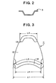
- FIG. 3 is a schematic back view of a bonnet for an automobile according to another embodiment
- FIG. 4 is a schematic partial sectional view of a conventional FRP bonnet for an automobile
- FIG. 5 is a schematic sectional view of the bonnet depicted in FIG. 4 , showing a state where a reactive force is generated;
- FIG. 6 is an enlarged cross-sectional view of an inner portion having a hat-shape section of the bonnet depicted in FIG. 4 ;
- FIG. 7 is a schematic cross-sectional view of an inner portion in a bonnet for an automobile according to a further embodiment, showing each of examples of great deformation possible sectional portions;
- FIG. 8 is a schematic cross-sectional view of an inner portion, showing each of other examples of great deformation possible sectional portions;
- FIG. 9 is a schematic cross-sectional view of an inner portion, showing an example of a rotational deformation possible sectional portion
- FIG. 10 is a schematic cross-sectional view of an inner portion, showing each of examples in a case where a great deformation possible sectional structure is added to a rotational deformation possible inner structure;
- FIG. 11 is a schematic cross-sectional view of an inner portion, showing each of other examples in a case where a great deformation possible sectional structure is added to a rotational deformation possible inner structure;
- FIG. 12A is an exploded perspective view of a bonnet for an automobile according to another embodiment with elongated side edges;
- FIG. 12B is a perspective view of a bonnet formed from an outer member and a pair of abutted inner members.
- FIG. 1 shows a bonnet for an automobile according to one embodiment.
- symbol 1 shows the whole of the bonnet for an automobile
- the bonnet 1 comprises an FRP outer member 2 positioned at a surface side, and FRP front inner member 3 and rear inner member 4 which are joined to the back surface side of the outer member and separated into two parts in a forward and backward direction of a vehicle body.
- FRP outer member 2 is spread in a plane direction over the entire surface of the bonnet, and formed as a curved shape required depending upon the kind of automobile.
- This outer member 2 may be formed as an FRP single plate structure, or may be formed as a sandwich structure in which a core material (for example, a core material formed from a foamed material) is interposed between FRP skin plates.
- a core material for example, a core material formed from a foamed material
- each of inner members 3 and 4 it is preferred to form the cross section of the inner member in a hat shape.
- hat-shape cross section 5 can be formed partially relative to each inner member, because the inner member is divided into two parts of inner members 3 and 4 and the inner member is not disposed at an unnecessary position, it is preferred to form each inner member in a hat-shape cross section substantially over the whole.
- front inner member 3 extends in the transverse direction of a vehicle body substantially over the entire width of outer member 2 , and further has portions each shortly extending along the outer edge of outer member 2 at both side portions.
- Rear inner member 4 also extends in the transverse direction of a vehicle body substantially over the entire width of outer member 2 , and further has portions each shortly extending along the outer edge of outer member 2 at both side portions.
- These front inner member 3 and rear inner member 4 are disposed in the forward and backward direction of a vehicle body with a space. However, it is possible to dispose both inner members at a condition where the portions shortly extending along the outer edge of outer member 2 are abutted to each other as shown in FIGS. 12A & 12B .
- this boundary portion becomes a low-rigidity portion extending in the transverse direction of a vehicle, and it becomes a trigger portion for bending deformation at a dogleg shape of outer member 2 at the time of a head-on collision, etc.
- a striker 6 is attached to front inner member 3 as a engaging member for opening/closing the bonnet via an adhesive or a bolt, etc.
- Fittings 7 for attaching a hinge (not shown) for operation of opening/closing the bonnet (operation of rotation) are attached to both sides of rear inner member 4 , and these hinge attaching fittings 7 may be attached via an adhesive or a bolt, etc.
- FRP in the bonnet for an automobile means a resin reinforced by reinforcing fibers, and as the reinforcing fibers, for example, inorganic fibers such as carbon fibers and glass fibers, and organic fibers such as KEVLAR® polyamide fibers, polyethylene fibers and polyamide fibers, can be exemplified. From the viewpoint of easy control of plane rigidity, particularly carbon fibers are preferred.
- a thermosetting resin such as an epoxy resin, an unsaturated polyester resin, a vinylester resin and a phenolic resin
- a thermoplastic resin such as a polyamide resin, a polyolefine resin, a dicyclopentadiene resin and a polyurethane resin also can be used.
- FRP comprising these reinforcing fibers and matrix resin as a single layer structure, in order to exhibit a desirable property (in particular, a desirable flexural rigidity or torsional rigidity in a specified direction), a lamination structure is preferred.
- the mechanical properties of FRP can be appropriately set by selection or combination of the above-described reinforcing fibers and matrix resin, orientation and volume content of the reinforcing fibers, the lamination structure, etc.
- the rigidity of the inner member and a difference in rigidity between inner parts can be appropriately set by a sectional shape of inner member (width, height, thickness, etc.), a length of inner member itself, extending shape of inner member, etc.
- an elastic material, a foamed material or a honeycomb material can be used, and for the purpose of lightening, a foamed material is particularly preferred.
- the material of the foamed material is not particularly limited, and for example, a foamed material of a polymer material such as a polyurethane, an acrylic, a polystyrene, a polyimide, a vinyl chloride, a phenol, etc. can be used.
- the honeycomb material is not particularly limited, and for example, an aluminum alloy, a paper, an aramide paper, etc. can be used.
- outer member 2 exhibits a necessary plane rigidity required for the bonnet 1 as a main structural member, and rigidity components lack at the front and rear portions are supplemented by joining front inner member 3 and rear inner member 4 divided into two parts. Since the inner member is separated into two parts in the forward and backward direction of a vehicle body and particularly in this embodiment, a portion of the outer member therebetween is formed as a low-rigidity portion which is not reinforced by the inner member and extends in the transverse direction of the vehicle body, at the time of collision accident, etc.
- the portion becomes a trigger portion for a dogleg-like shape bending deformation, and from the viewpoint of relaxing an impact given to a pedestrian and protecting a crew, it becomes possible that the whole of bonnet 1 is bent in a desirable direction and at a desirable form of a dogleg-like shape.
- front inner member 3 and rear inner member 4 become much smaller that the size of a conventional picture-frame like inner member, the production thereof due to RTM molding or SMC molding is facilitated, molds therefor may be small, the scale of the equipment therefor may be small, and the cost for the equipment may be inexpensive. Further, because the small-sized front inner member 3 and rear inner member 4 are joined to outer member 2 , the accuracy for positioning can be easily improved. Furthermore, attachment of striker 6 and hinge attaching fittings 7 to front inner member 3 and rear inner member 4 can be easily carried out, and functions required for operation can also be easily satisfied.
- a structure wherein a difference in rigidity is given between two inner parts.
- a structure providing a difference between cross-sectional shapes of both inner members can be employed, a structure providing a difference between lamination structures of FRPs forming both inner members, a structure providing a difference between kinds of reinforcing fibers of FRPs forming both inner members and, further, a structure providing a difference between lengths in the transverse direction of vehicle body of both inner members, in particular, a structure adding a device to the extending shape of the rear inner member.
- FIG. 3 An example is shown in FIG. 3 .
- a difference in length in the transverse direction of a vehicle body is given between FRP front inner member 13 and rear inner member 14 joined to FRP outer member 12 , and a length L 1 of rear inner member 14 is set longer than a length L 2 of front inner member 13 .
- a distance L 3 between both hinges determined along the shape of rear inner member 14 is set longer than a distance L 4 between both hinges determined linearly, by 1.2 times or more.
- FIG. 3 shows each inner member completely along the outer edge of the outer member, the inner member may be present at an inside position within the outer edge of the outer member, and the outer edge of the outer member may be greater than the size of the inner member toward outside.
- a structure having a great deformation possible sectional portion (a great deformation possible section inner structure), or a structure formed in a rotational deformation possible shape capable of being rotationally deformed toward a central portion side in a plane direction of the bonnet (a rotational deformation possible inner structure), can be employed.
- FIG. 4 shows a usual setting state of the front side of a conventional FRP bonnet for an automobile.
- an FRP outer member 22 is formed as a sandwich structure in which a core material 25 is interposed between FRP skin plates 23 and 24 , and the circumferential edge portion is formed as an FRP single plate structure as an extended portion of FRP skin plate 23 . It is also possible to form the FRP outer member as an FRP single plate structure over the entire area.
- An FRP inner member 26 is joined to a necessary portion at the back surface side of this FRP outer member 22 .
- Inner member 26 functions as a stiffener for reinforcing a portion of outer member 22 lack in rigidity, and for example, as shown in the figure, it has a stiffener-structure cross section with a hat shape.
- a predetermined gap is provided between inner member 26 (in particular, the bottom surface of inner member 26 ) and the vehicle body side 27 including an inside mounted material (hereinafter, called as the “vehicle body side” including structural materials 27 a , 27 b , etc. shown in the figure).
- FRP inner member 26 is formed as a great deformation possible sectional portion capable of being greatly deformed by a vertical load.
- the rigidity of the outer member is extremely high, the advantage due to this reduction of the reaction force by providing a great deformation possible sectional portion to FRP inner member 26 is great.
- this hat-shape stiffener-structure cross-sectional portion as a great deformation possible structure, for example, the'following various structures can be employed.
- a shape of the cross section for example, it can be formed as shown in FIG. 7 (A), (B), (C) or (D).
- a sectional structure 33 is employed wherein each of rising surface parts 31 and 32 at both sides of the hat shape is formed as a polygonal line shape protruding toward outside
- a sectional structure 36 is employed wherein each of rising surface parts 34 and 35 at both sides of the hat shape is formed as a polygonal line shape protruding toward inside.
- a sectional structure 39 is employed wherein each of rising surface parts 37 and 38 at both sides of the hat shape is formed as a stepped shape
- a sectional structure 42 is employed wherein each of rising surface parts 40 and 41 at both sides of the hat shape is formed as a bent curved shape. Also in such a sectional shape, an excellent energy absorbing performance can be exhibited similarly to that in FIG. 7(A) or 7 (B).
- FIGS. 8 (A), (B), (C) and (D) the above-described great deformation possible cross-sectional shapes can be combined arbitrarily for the rising surface parts at both sides of the hat shape, and further, it is possible to form a great deformation possible cross-sectional shape only on one rising surface part of the hat shape.
- a sectional structure 45 is employed wherein one rising surface part 43 of the hat shape is formed as a polygonal line shape protruding toward outside and the other rising surface part 44 is formed as a polygonal line shape protruding toward inside, and in the structure shown in FIG.
- a sectional structure 48 is employed wherein one rising surface part 46 of the hat shape is left as a straight shape and only the other rising surface part 47 is formed as a polygonal line shape protruding toward inside.
- a sectional structure 51 is employed wherein one rising surface part 49 is left as a straight shape and only the other rising surface part 50 is formed as a stepped shape
- a sectional structure 54 is employed wherein one rising surface part 52 of the hat shape is formed as a shape curved toward inside and the other rising surface part 53 is formed as a bent curved shape.
- a great deformation possible sectional portion is formed by the shape of the section in FIGS. 7 and 8 , it is possible to form a great deformation possible sectional portion having a similar function by other methods.
- it can be achieved by a structure wherein the thickness of a rising surface part of the hat shape of the FRP inner member is partially made smaller, or by a structure wherein the lamination structure of FRP of a rising surface part of the hat shape is partially changed.
- a method for partially reducing the number of the lamination of the reinforcing fiber layers of the rising surface part can be employed, and as the method for partially changing the lamination structure of FRP, for example, a method for partially changing the angle of the orientation of the reinforcing fibers of the reinforcing fiber layers laminated on the rising surface part to an angle easily deformed, a method for partially changing the kind of the reinforcing fibers, etc. can be employed.
- the above-described great deformation possible sectional portion can be set partially at a position to be required.
- a striker and the like is provided to a front part (front side of vehicle body) of the bonnet and hinge attaching fittings and the like are provided to a rear part thereof (rear side of vehicle body) and a high rigidity due to joining of the inner member has to be given to both parts, because side parts do not require such a high rigidity, it is preferred that the contact with a fender becomes soft and the above-described great deformation possible sectional portion is applied thereto.
- the contact with the vehicle body side can be soft by employing the above-described great deformation possible sectional portion.
- the inner part extends by a predetermined length along the outer edge and the like of the outer member, it is also possible to provide the above-described great deformation possible sectional portion to a required portion in the extending direction of the inner part.
- the inner member has both of the great deformation possible sectional portion and a usual sectional portion which is not formed as a structure capable of being greatly deformed at a rising surface part of the hat shape by a vertical load (for example, a usual hat-shaped sectional portion as shown in FIG. 6 )
- a structure can also be employed wherein the sectional structure is gradually changed between the great deformation possible sectional portion and the usual sectional portion.
- an inner structure for example, as shown in FIG. 9 , can be employed.
- a part of inner member 61 has a cross section of a stiffener structure with a schematic hat shape, and a bottom surface 62 of inner member 61 is inclined relative to a facing surface 63 of vehicle body side.
- inner member 61 is formed in a rotational deformation possible shape capable of being rotationally deformed toward a central portion in the plane direction of bonnet 64 (in the figure, in the arrow direction Y) after a part of bottom surface 62 of inner member 61 comes into contact with the vehicle body side facing surface 63 .
- this rotational deformation possible shape is formed by setting the lengths and rising angles of rising surface parts 65 and 66 of the schematic hat shape different from each other depending on the inclination of bottom surface 62 .
- bonnet 64 having such a structure, when an impact load is applied to outer member 67 from the upper side, the outer member 67 is deformed downward, a part of bottom surface 62 of inner member 61 (a corner portion) comes into contact with vehicle body side facing surface 63 , and as shown by the dotted line in the figure, namely, it is deformed so as to be rotated toward the central portion side in the plane direction of bonnet 64 (in the figure, in the arrow direction Y). Because of deformation toward the inside of the vehicle body, as compared with deformation toward outside, the deformation can be performed at a condition where there is no obstruction, or even if there is an obstruction, it does not become a great obstruction, and the deformation is proceeded smoothly and softly.
- a rotational moment 68 is generated, and this rotational moment 68 operates so as to absorb a collision energy applied from outside. Moreover, because at that time the inner member 61 itself being rotationally deformed can absorb the energy, the energy absorbing performance as the whole of the bonnet can be further increased.
- the rigidity of outer member 67 is extremely high, by applying such a structure to FRP inner member 61 , an extremely excellent relaxation effect can be obtained for the aforementioned reaction force from the vehicle body side. Therefore, the collision energy is smoothly absorbed, a desirable energy absorbing performance can be exhibited, and a pedestrian at the time of collision, particularly, the head of the pedestrian, is adequately protected.
- the inner member having the above-described structure is formed preferably as a structure wherein at least one of the rising surface parts of the schematic hat shape is further formed as a great deformation possible sectional portion capable of being greatly deformed by a vertical load.
- a shape of the cross section for example, it can be formed as shown in FIG. 10 (A), (B), (C) or (D).
- a sectional structure 73 is employed wherein one rising surface part 71 of the schematic hat shape is formed as a polygonal line shape protruding toward outside, and the other rising surface part 72 is formed as a straight shape
- a sectional structure 76 is employed wherein rising surface parts 74 and 75 at both sides of the schematic hat shape are formed as stepped shapes, in the structure shown in FIG.
- a sectional structure 79 is employed wherein one rising surface part 77 of the schematic hat shape is formed as a polygonal line shape protruding toward inside, and the other rising surface part 78 is formed as a straight shape, and in the structure shown in FIG. 10(D) , a sectional structure 82 is employed wherein one rising surface part 80 of the schematic hat shape is formed as a curved bent shape, and the other rising surface part 81 is formed as a shape curved toward inside.
- the sectional shape having a great deformation possible sectional portion can further employ various shapes.
- FIGS. 11 (A), (B), (C) and (D) schematic hat-shape inner sectional shapes 91 , 92 , 93 and 94 can be employed, and further, it is possible to employ shapes other than those depicted in the figures.
- a great deformation possible sectional portion is formed by the shape of the section in FIGS. 10 and 11 , it is possible to form a great deformation possible sectional portion having a similar function by other methods.
- it can be achieved by a structure wherein the thickness of a rising surface part of the schematic hat shape of the FRP inner member is partially made smaller, or by a structure wherein the lamination structure of FRP of a rising surface part of the schematic hat shape is partially changed.
- a method for partially reducing the number of the lamination of the reinforcing fiber layers of the rising surface part can be employed, and as the method for partially changing the lamination structure of FRP, for example, a method for partially changing the angle of the orientation of the reinforcing fibers of the reinforcing fiber layers laminated on the rising surface part to an angle easily deformed, a method for partially changing the kind of the reinforcing fibers, etc. can be employed.
- the sectional portion having the above-described rotational deformation possible portion and further the above-described great deformation possible sectional portion can be set partially at a position to be required.
- a striker and the like is provided to a front part (front side of vehicle body) of the bonnet and hinge attaching fittings and the like are provided to a rear part thereof (rear side of vehicle body) and a high rigidity due to joining of the inner member has to be given to both parts, in portions other than the portions attached with these members, an inner sectional shape capable of being greatly deformed can be employed.
- the inner part extends by a predetermined length along the outer edge and the like of the outer member, it is also possible to provide the above-described rotational deformation possible portion and further the above-described great deformation possible sectional portion to a required portion in the extending direction of the inner part.
- the inner member has both of the rotational deformation possible portion, further the great deformation possible sectional portion, and a usual sectional portion which is not formed as such a structure (for example, a usual hat-shaped sectional portion as shown in FIG. 6 )
- a structure can also be employed wherein the sectional structure is gradually changed between the rotational deformation possible portion, the great deformation possible sectional portion, and the usual sectional portion.
- the rotation direction of the inner member of the schematic hat-shape section is set in a direction toward a central portion side in a plane direction of the bonnet, as aforementioned.
- the right side of a vehicle body (the driver seat side of a right handle automobile)
- it is set as a counter clockwise direction as viewed from the front side of the vehicle body, as to the left side of a vehicle body (the side of a seat beside the driver of a right handle automobile), as a clockwise direction as viewed from the front side of the vehicle body, as to a front edge, as a counter clockwise direction as viewed from the left side of the vehicle body, as to a front edge, as a clockwise direction as viewed from the left side of the vehicle body, respectively.
- the FRP bonnet for an automobile can be applied to any bonnet for an automobile for which a lightness is required as a whole and an effective impact absorbing performance due to a predetermined deformation and an excellent productivity are required.
Applications Claiming Priority (3)
| Application Number | Priority Date | Filing Date | Title |
|---|---|---|---|
| JP2004252335 | 2004-08-31 | ||
| JP2004-252335 | 2004-08-31 | ||
| PCT/JP2005/015646 WO2006025315A1 (ja) | 2004-08-31 | 2005-08-29 | 自動車用ボンネット |
Publications (2)
| Publication Number | Publication Date |
|---|---|
| US20080066983A1 US20080066983A1 (en) | 2008-03-20 |
| US8075048B2 true US8075048B2 (en) | 2011-12-13 |
Family
ID=35999969
Family Applications (1)
| Application Number | Title | Priority Date | Filing Date |
|---|---|---|---|
| US11/661,443 Expired - Fee Related US8075048B2 (en) | 2004-08-31 | 2005-08-29 | Bonnet for automobile having automobiles that protects the heads of pedestrians |
Country Status (7)
| Country | Link |
|---|---|
| US (1) | US8075048B2 (de) |
| EP (1) | EP1792807B1 (de) |
| JP (1) | JP4873309B2 (de) |
| AT (1) | ATE473902T1 (de) |
| AU (1) | AU2005278583A1 (de) |
| DE (1) | DE602005022327D1 (de) |
| WO (1) | WO2006025315A1 (de) |
Cited By (8)
| Publication number | Priority date | Publication date | Assignee | Title |
|---|---|---|---|---|
| US20110121608A1 (en) * | 2009-09-17 | 2011-05-26 | Gm Global Technology Operations, Inc. | Body for a motor vehicle |
| US20120043786A1 (en) * | 2009-01-23 | 2012-02-23 | Renault S.A.S. | Automobile comprising a front bumper with a central portion extending as far as the bonnet of said vehicle |
| US20120217761A1 (en) * | 2011-02-25 | 2012-08-30 | Honda Motor Co., Ltd. | Front Body Structure for Vehicle |
| US20140110971A1 (en) * | 2011-04-26 | 2014-04-24 | Mahindra & Mahindra Limited | Ladder Honeycomb Hood Structure For A Motor Vehicle For Pedestrian Protection |
| US8740291B2 (en) | 2010-12-03 | 2014-06-03 | Nissan Motor Co., Ltd. | Hood inner panel |
| US20160229464A1 (en) * | 2015-02-05 | 2016-08-11 | Toyota Jidosha Kabushiki Kaisha | Vehicle panel structure and manufacturing method of vehicle panel structure |
| US20170016503A1 (en) * | 2014-02-24 | 2017-01-19 | Teijin Limited | Resin-Made Impact Absorption Member |
| US20170297629A1 (en) * | 2016-04-14 | 2017-10-19 | Hyundai Motor Company | Hood panel for vehicle |
Families Citing this family (10)
| Publication number | Priority date | Publication date | Assignee | Title |
|---|---|---|---|---|
| DE102005017567A1 (de) * | 2005-04-16 | 2006-10-19 | Daimlerchrysler Ag | Kraftwagenbug |
| JP2009035045A (ja) * | 2007-07-31 | 2009-02-19 | Toray Ind Inc | Frp製自動車用部材 |
| DE102007053171A1 (de) * | 2007-11-08 | 2009-05-14 | Dr. Ing. H.C. F. Porsche Aktiengesellschaft | Motorhaube für ein Kraftfahrzeug |
| DE102013203337A1 (de) * | 2012-03-30 | 2013-10-02 | Fuji Jukogyo K.K. | Fahrzeug |
| JP6007615B2 (ja) * | 2012-06-22 | 2016-10-12 | マツダ株式会社 | 樹脂製リッド構造 |
| US8758879B2 (en) | 2012-06-24 | 2014-06-24 | The Boeing Company | Composite hat stiffener, composite hat-stiffened pressure webs, and methods of making the same |
| JP6172848B2 (ja) | 2012-09-26 | 2017-08-02 | 株式会社Subaru | 車両 |
| JP6148915B2 (ja) | 2012-09-26 | 2017-06-14 | 株式会社Subaru | 車両 |
| US10308343B2 (en) * | 2013-05-30 | 2019-06-04 | The Boeing Company | Composite hat stiffener |
| CN203713981U (zh) | 2013-12-19 | 2014-07-16 | 全耐塑料公司 | 机动车关闭件的结构部件及包含该部件的机动车关闭件 |
Citations (32)
| Publication number | Priority date | Publication date | Assignee | Title |
|---|---|---|---|---|
| US2709108A (en) * | 1951-07-11 | 1955-05-24 | Budd Co | Trunk lid or the like for automobile |
| US3709316A (en) * | 1971-10-26 | 1973-01-09 | Ford Motor Co | Cam action safety hood |
| US4359120A (en) * | 1979-08-23 | 1982-11-16 | Daimler-Benz A.G. | Passenger motor vehicle with yielding body front sections |
| JPS6370478A (ja) | 1986-09-12 | 1988-03-30 | Toshiba Corp | 精密回折格子の製造方法 |
| US5000997A (en) * | 1989-02-06 | 1991-03-19 | The Budd Company | Method for making a painted part and part made thereby |
| US5124191A (en) * | 1991-03-11 | 1992-06-23 | Aluminum Company Of America | Structural panel |
| US5605371A (en) * | 1994-04-25 | 1997-02-25 | Inland Steel Company | Light weight steel auto body construction |
| US5682667A (en) * | 1996-04-10 | 1997-11-04 | The Budd Company | Method for preventing damage to an overslam bumper pocket |
| JPH11208511A (ja) | 1998-01-23 | 1999-08-03 | Honda Motor Co Ltd | 自動車のフード用合成樹脂製パネル |
| US5988305A (en) * | 1994-04-18 | 1999-11-23 | Nissan Motor Co., Ltd. | Front upper structure of automotive vehicle |
| US6237992B1 (en) * | 1999-08-21 | 2001-05-29 | Ford Global Technologies, Inc. | Pedestrian safety module device |
| US20010002761A1 (en) * | 1999-12-06 | 2001-06-07 | Honda Giken Kogyo Kabushiki Kaisha | Vehicle body structure for improved crash safety |
| JP2001301658A (ja) | 2000-04-25 | 2001-10-31 | Nissan Motor Co Ltd | フード構造 |
| US6398286B1 (en) * | 1999-09-09 | 2002-06-04 | Usinor | Reinforced and lightweight motor-vehicle bonnett |
| JP2002284038A (ja) | 2001-03-29 | 2002-10-03 | Toray Ind Inc | 自動車用パネル |
| US6543086B2 (en) * | 1999-05-25 | 2003-04-08 | Volvo Car Corporation | Collapsible hood hinge |
| JP2003146252A (ja) | 2001-11-14 | 2003-05-21 | Toray Ind Inc | Frp製自動車用パネルおよびその製造方法 |
| US20040251716A1 (en) * | 2003-06-11 | 2004-12-16 | Choi In Ho | Multistage impact absorption structure for a fender mounting part |
| US20060011434A1 (en) * | 2004-07-14 | 2006-01-19 | Kojima Press Industry Co., Ltd. | Shock absorbing structure for motor vehicle and shock absorbing assembly including the same |
| US7052079B2 (en) * | 2003-07-01 | 2006-05-30 | Toyota Jidosha Kabushiki Kaisha | Vehicular hood structure and vehicle body front portion structure |
| US7055894B2 (en) * | 2003-09-01 | 2006-06-06 | Toyota Jidosha Kabushiki Kaisha | Vehicular hood structure |
| US7481488B2 (en) * | 2003-09-22 | 2009-01-27 | Toyota Jidosha Kabushiki Kaisha | Vehicle hood structure |
| US20090025995A1 (en) * | 2007-07-24 | 2009-01-29 | Gm Global Technology Operations, Inc. | Vehicle Hood With Sandwich Inner Structure |
| US20090026807A1 (en) * | 2007-07-24 | 2009-01-29 | Gm Global Technology Operations, Inc. | Energy-Absorbing Vehicle Hood Assembly with Cushion Inner Structure |
| US7488031B2 (en) * | 2006-07-07 | 2009-02-10 | Kobe Steel, Ltd. | Automotive engine hood |
| US7497507B2 (en) * | 2004-08-31 | 2009-03-03 | Toray Industries, Inc. | Bonnet for automobile |
| US20090065277A1 (en) * | 2007-09-11 | 2009-03-12 | Gm Global Technology Operations, Inc. | Vehicle Hood Assembly with Rippled Cushion Support |
| US20090167060A1 (en) * | 2005-12-01 | 2009-07-02 | Inoplast | Vehicle Hood and a Method of Fabricating Such a Hood |
| US20090195020A1 (en) * | 2008-01-31 | 2009-08-06 | Gm Global Technology Operations, Inc. | Energy Absorbing Vehicle Hood Assembly with Asymmetric Sandwich Inner Structure |
| US7810877B2 (en) * | 2006-03-15 | 2010-10-12 | Kobe Steel, Ltd. | Automobile hood |
| US20100314907A1 (en) * | 2008-02-04 | 2010-12-16 | Toyota Jidosha Kabushiki Kaisha | Vehicular hood structure |
| US20110139533A1 (en) * | 2009-12-14 | 2011-06-16 | GM Global Technology Operations LLC | Body for a motor vehicle |
Family Cites Families (10)
| Publication number | Priority date | Publication date | Assignee | Title |
|---|---|---|---|---|
| JPH0631011B2 (ja) * | 1985-06-07 | 1994-04-27 | マツダ株式会社 | 自動車のリツド構造 |
| JPS6370478U (de) * | 1986-10-28 | 1988-05-11 | ||
| JPS63112179A (ja) * | 1986-10-30 | 1988-05-17 | Canon Inc | 記録装置 |
| JPH0412866Y2 (de) * | 1987-02-06 | 1992-03-26 | ||
| JPH01144280A (ja) * | 1987-11-30 | 1989-06-06 | Mitsubishi Electric Corp | 磁気ディスク装置 |
| JPH0296371A (ja) * | 1988-09-30 | 1990-04-09 | Mitsubishi Electric Corp | 半導体装置 |
| JP3632423B2 (ja) * | 1998-01-13 | 2005-03-23 | 日産自動車株式会社 | フードインナ構造 |
| JP2000001182A (ja) * | 1998-06-16 | 2000-01-07 | Fuji Heavy Ind Ltd | 車両用フロントフード構造 |
| JP2001191962A (ja) * | 2000-01-12 | 2001-07-17 | Toray Ind Inc | Frp補強自動車用水平パネル材 |
| DE10232799B4 (de) * | 2002-07-19 | 2016-10-27 | Volkswagen Ag | Vorbaustruktur an Kraftfahrzeugen |
-
2005
- 2005-08-29 EP EP05781050A patent/EP1792807B1/de not_active Not-in-force
- 2005-08-29 AT AT05781050T patent/ATE473902T1/de not_active IP Right Cessation
- 2005-08-29 WO PCT/JP2005/015646 patent/WO2006025315A1/ja active Application Filing
- 2005-08-29 AU AU2005278583A patent/AU2005278583A1/en not_active Abandoned
- 2005-08-29 US US11/661,443 patent/US8075048B2/en not_active Expired - Fee Related
- 2005-08-29 DE DE602005022327T patent/DE602005022327D1/de active Active
- 2005-08-29 JP JP2006532666A patent/JP4873309B2/ja not_active Expired - Fee Related
Patent Citations (32)
| Publication number | Priority date | Publication date | Assignee | Title |
|---|---|---|---|---|
| US2709108A (en) * | 1951-07-11 | 1955-05-24 | Budd Co | Trunk lid or the like for automobile |
| US3709316A (en) * | 1971-10-26 | 1973-01-09 | Ford Motor Co | Cam action safety hood |
| US4359120A (en) * | 1979-08-23 | 1982-11-16 | Daimler-Benz A.G. | Passenger motor vehicle with yielding body front sections |
| JPS6370478A (ja) | 1986-09-12 | 1988-03-30 | Toshiba Corp | 精密回折格子の製造方法 |
| US5000997A (en) * | 1989-02-06 | 1991-03-19 | The Budd Company | Method for making a painted part and part made thereby |
| US5124191A (en) * | 1991-03-11 | 1992-06-23 | Aluminum Company Of America | Structural panel |
| US5988305A (en) * | 1994-04-18 | 1999-11-23 | Nissan Motor Co., Ltd. | Front upper structure of automotive vehicle |
| US5605371A (en) * | 1994-04-25 | 1997-02-25 | Inland Steel Company | Light weight steel auto body construction |
| US5682667A (en) * | 1996-04-10 | 1997-11-04 | The Budd Company | Method for preventing damage to an overslam bumper pocket |
| JPH11208511A (ja) | 1998-01-23 | 1999-08-03 | Honda Motor Co Ltd | 自動車のフード用合成樹脂製パネル |
| US6543086B2 (en) * | 1999-05-25 | 2003-04-08 | Volvo Car Corporation | Collapsible hood hinge |
| US6237992B1 (en) * | 1999-08-21 | 2001-05-29 | Ford Global Technologies, Inc. | Pedestrian safety module device |
| US6398286B1 (en) * | 1999-09-09 | 2002-06-04 | Usinor | Reinforced and lightweight motor-vehicle bonnett |
| US20010002761A1 (en) * | 1999-12-06 | 2001-06-07 | Honda Giken Kogyo Kabushiki Kaisha | Vehicle body structure for improved crash safety |
| JP2001301658A (ja) | 2000-04-25 | 2001-10-31 | Nissan Motor Co Ltd | フード構造 |
| JP2002284038A (ja) | 2001-03-29 | 2002-10-03 | Toray Ind Inc | 自動車用パネル |
| JP2003146252A (ja) | 2001-11-14 | 2003-05-21 | Toray Ind Inc | Frp製自動車用パネルおよびその製造方法 |
| US20040251716A1 (en) * | 2003-06-11 | 2004-12-16 | Choi In Ho | Multistage impact absorption structure for a fender mounting part |
| US7052079B2 (en) * | 2003-07-01 | 2006-05-30 | Toyota Jidosha Kabushiki Kaisha | Vehicular hood structure and vehicle body front portion structure |
| US7055894B2 (en) * | 2003-09-01 | 2006-06-06 | Toyota Jidosha Kabushiki Kaisha | Vehicular hood structure |
| US7481488B2 (en) * | 2003-09-22 | 2009-01-27 | Toyota Jidosha Kabushiki Kaisha | Vehicle hood structure |
| US20060011434A1 (en) * | 2004-07-14 | 2006-01-19 | Kojima Press Industry Co., Ltd. | Shock absorbing structure for motor vehicle and shock absorbing assembly including the same |
| US7497507B2 (en) * | 2004-08-31 | 2009-03-03 | Toray Industries, Inc. | Bonnet for automobile |
| US20090167060A1 (en) * | 2005-12-01 | 2009-07-02 | Inoplast | Vehicle Hood and a Method of Fabricating Such a Hood |
| US7810877B2 (en) * | 2006-03-15 | 2010-10-12 | Kobe Steel, Ltd. | Automobile hood |
| US7488031B2 (en) * | 2006-07-07 | 2009-02-10 | Kobe Steel, Ltd. | Automotive engine hood |
| US20090026807A1 (en) * | 2007-07-24 | 2009-01-29 | Gm Global Technology Operations, Inc. | Energy-Absorbing Vehicle Hood Assembly with Cushion Inner Structure |
| US20090025995A1 (en) * | 2007-07-24 | 2009-01-29 | Gm Global Technology Operations, Inc. | Vehicle Hood With Sandwich Inner Structure |
| US20090065277A1 (en) * | 2007-09-11 | 2009-03-12 | Gm Global Technology Operations, Inc. | Vehicle Hood Assembly with Rippled Cushion Support |
| US20090195020A1 (en) * | 2008-01-31 | 2009-08-06 | Gm Global Technology Operations, Inc. | Energy Absorbing Vehicle Hood Assembly with Asymmetric Sandwich Inner Structure |
| US20100314907A1 (en) * | 2008-02-04 | 2010-12-16 | Toyota Jidosha Kabushiki Kaisha | Vehicular hood structure |
| US20110139533A1 (en) * | 2009-12-14 | 2011-06-16 | GM Global Technology Operations LLC | Body for a motor vehicle |
Cited By (14)
| Publication number | Priority date | Publication date | Assignee | Title |
|---|---|---|---|---|
| US20120043786A1 (en) * | 2009-01-23 | 2012-02-23 | Renault S.A.S. | Automobile comprising a front bumper with a central portion extending as far as the bonnet of said vehicle |
| US8491038B2 (en) * | 2009-01-23 | 2013-07-23 | Hicham Challal | Automobile comprising a front bumper with a central portion extending as far as the bonnet of said vehicle |
| US20110121608A1 (en) * | 2009-09-17 | 2011-05-26 | Gm Global Technology Operations, Inc. | Body for a motor vehicle |
| US8740291B2 (en) | 2010-12-03 | 2014-06-03 | Nissan Motor Co., Ltd. | Hood inner panel |
| US9097042B2 (en) * | 2011-02-25 | 2015-08-04 | Honda Motor Co., Ltd. | Front body structure for vehicle |
| US20120217761A1 (en) * | 2011-02-25 | 2012-08-30 | Honda Motor Co., Ltd. | Front Body Structure for Vehicle |
| US20140110971A1 (en) * | 2011-04-26 | 2014-04-24 | Mahindra & Mahindra Limited | Ladder Honeycomb Hood Structure For A Motor Vehicle For Pedestrian Protection |
| US9283923B2 (en) * | 2011-04-26 | 2016-03-15 | Mahindra And Mahindra Limited | Ladder honeycomb hood structure for a motor vehicle for pedestrian protection |
| US20170016503A1 (en) * | 2014-02-24 | 2017-01-19 | Teijin Limited | Resin-Made Impact Absorption Member |
| US11137044B2 (en) * | 2014-02-24 | 2021-10-05 | Teijin Limited | Resin-made impact absorption member |
| US20160229464A1 (en) * | 2015-02-05 | 2016-08-11 | Toyota Jidosha Kabushiki Kaisha | Vehicle panel structure and manufacturing method of vehicle panel structure |
| US10017213B2 (en) * | 2015-02-05 | 2018-07-10 | Toyota Jidosha Kabushiki Kaisha | Vehicle panel structure and manufacturing method of vehicle panel structure |
| US20170297629A1 (en) * | 2016-04-14 | 2017-10-19 | Hyundai Motor Company | Hood panel for vehicle |
| US10046807B2 (en) * | 2016-04-14 | 2018-08-14 | Hyundai Motor Company | Hood panel for vehicle |
Also Published As
| Publication number | Publication date |
|---|---|
| US20080066983A1 (en) | 2008-03-20 |
| JP4873309B2 (ja) | 2012-02-08 |
| EP1792807B1 (de) | 2010-07-14 |
| EP1792807A4 (de) | 2009-04-29 |
| DE602005022327D1 (de) | 2010-08-26 |
| WO2006025315A1 (ja) | 2006-03-09 |
| ATE473902T1 (de) | 2010-07-15 |
| EP1792807A1 (de) | 2007-06-06 |
| JPWO2006025315A1 (ja) | 2008-05-08 |
| AU2005278583A1 (en) | 2006-03-09 |
Similar Documents
| Publication | Publication Date | Title |
|---|---|---|
| US8075048B2 (en) | Bonnet for automobile having automobiles that protects the heads of pedestrians | |
| EP2316711B1 (de) | FK-Paneel für Kraftfahrzeuge | |
| US7497507B2 (en) | Bonnet for automobile | |
| JP2005238837A (ja) | Frp積層構造体 | |
| JP2007176328A (ja) | Frp構造体 | |
| US8267428B2 (en) | Energy absorbing countermeasure | |
| JP2005231618A (ja) | 自動車用外板部材 | |
| JP2008302749A (ja) | 自動車用フードパネル | |
| JP4802617B2 (ja) | 自動車用ボンネット | |
| JP2008213437A (ja) | Frp構造体 | |
| JP2008007012A (ja) | 繊維強化プラスチック製自動車用フードパネル | |
| JP2011020614A (ja) | 自動車用フードパネル | |
| JP5062956B2 (ja) | 自動車用外板部材 | |
| JP5881117B2 (ja) | 自動車の車体構造 | |
| US20220169097A1 (en) | Composite vehicle components formed of sheet molding compound reinforced with continuous fibers | |
| JP2005238836A (ja) | Frp構造体 | |
| JPH06305378A (ja) | 車両用バンパー | |
| WO2012153601A1 (ja) | 車体前部構造体 | |
| WO2014097765A1 (ja) | 自動車の車体構造 | |
| JP2006069316A (ja) | 自動車用ボンネット | |
| JP4392596B2 (ja) | Frp構造体 | |
| CN117585068A (zh) | 后车身结构 | |
| JP2005219711A (ja) | 自動車用外板部材 | |
| KR20230121699A (ko) | 차량용 범퍼 백빔 | |
| JP2006069320A (ja) | 自動車用ボンネット |
Legal Events
| Date | Code | Title | Description |
|---|---|---|---|
| AS | Assignment |
Owner name: TORAY INDUSTRIES, INC., JAPAN Free format text: ASSIGNMENT OF ASSIGNORS INTEREST;ASSIGNORS:KIMOTO, YUKITANE;KIYAMA, HIROSHI;REEL/FRAME:019002/0933 Effective date: 20070222 |
|
| STCF | Information on status: patent grant |
Free format text: PATENTED CASE |
|
| FPAY | Fee payment |
Year of fee payment: 4 |
|
| FEPP | Fee payment procedure |
Free format text: MAINTENANCE FEE REMINDER MAILED (ORIGINAL EVENT CODE: REM.); ENTITY STATUS OF PATENT OWNER: LARGE ENTITY |
|
| LAPS | Lapse for failure to pay maintenance fees |
Free format text: PATENT EXPIRED FOR FAILURE TO PAY MAINTENANCE FEES (ORIGINAL EVENT CODE: EXP.); ENTITY STATUS OF PATENT OWNER: LARGE ENTITY |
|
| STCH | Information on status: patent discontinuation |
Free format text: PATENT EXPIRED DUE TO NONPAYMENT OF MAINTENANCE FEES UNDER 37 CFR 1.362 |
|
| FP | Lapsed due to failure to pay maintenance fee |
Effective date: 20191213 |