US8072177B2 - Stepping motor driver - Google Patents
Stepping motor driver Download PDFInfo
- Publication number
- US8072177B2 US8072177B2 US12/206,096 US20609608A US8072177B2 US 8072177 B2 US8072177 B2 US 8072177B2 US 20609608 A US20609608 A US 20609608A US 8072177 B2 US8072177 B2 US 8072177B2
- Authority
- US
- United States
- Prior art keywords
- signal
- output
- induced voltage
- current
- unit
- Prior art date
- Legal status (The legal status is an assumption and is not a legal conclusion. Google has not performed a legal analysis and makes no representation as to the accuracy of the status listed.)
- Expired - Fee Related, expires
Links
- 238000001514 detection method Methods 0.000 claims abstract description 72
- 230000004044 response Effects 0.000 claims description 6
- 230000001172 regenerating effect Effects 0.000 claims 1
- 230000003287 optical effect Effects 0.000 description 16
- 238000000034 method Methods 0.000 description 9
- 230000008929 regeneration Effects 0.000 description 8
- 238000011069 regeneration method Methods 0.000 description 8
- 230000003111 delayed effect Effects 0.000 description 4
- 230000010363 phase shift Effects 0.000 description 3
- 230000000630 rising effect Effects 0.000 description 3
- 230000002411 adverse Effects 0.000 description 1
- 230000000694 effects Effects 0.000 description 1
- 238000005259 measurement Methods 0.000 description 1
- 230000004043 responsiveness Effects 0.000 description 1
- 230000001360 synchronised effect Effects 0.000 description 1
Images


Classifications
-
- H—ELECTRICITY
- H02—GENERATION; CONVERSION OR DISTRIBUTION OF ELECTRIC POWER
- H02P—CONTROL OR REGULATION OF ELECTRIC MOTORS, ELECTRIC GENERATORS OR DYNAMO-ELECTRIC CONVERTERS; CONTROLLING TRANSFORMERS, REACTORS OR CHOKE COILS
- H02P8/00—Arrangements for controlling dynamo-electric motors rotating step by step
- H02P8/22—Control of step size; Intermediate stepping, e.g. microstepping
-
- H—ELECTRICITY
- H02—GENERATION; CONVERSION OR DISTRIBUTION OF ELECTRIC POWER
- H02P—CONTROL OR REGULATION OF ELECTRIC MOTORS, ELECTRIC GENERATORS OR DYNAMO-ELECTRIC CONVERTERS; CONTROLLING TRANSFORMERS, REACTORS OR CHOKE COILS
- H02P8/00—Arrangements for controlling dynamo-electric motors rotating step by step
- H02P8/34—Monitoring operation
-
- Y—GENERAL TAGGING OF NEW TECHNOLOGICAL DEVELOPMENTS; GENERAL TAGGING OF CROSS-SECTIONAL TECHNOLOGIES SPANNING OVER SEVERAL SECTIONS OF THE IPC; TECHNICAL SUBJECTS COVERED BY FORMER USPC CROSS-REFERENCE ART COLLECTIONS [XRACs] AND DIGESTS
- Y02—TECHNOLOGIES OR APPLICATIONS FOR MITIGATION OR ADAPTATION AGAINST CLIMATE CHANGE
- Y02P—CLIMATE CHANGE MITIGATION TECHNOLOGIES IN THE PRODUCTION OR PROCESSING OF GOODS
- Y02P80/00—Climate change mitigation technologies for sector-wide applications
- Y02P80/10—Efficient use of energy, e.g. using compressed air or pressurized fluid as energy carrier
Definitions
- the present invention relates to a stepping motor driver, and particularly relates to a stepping motor driver which determines whether an optical pickup is stopped or not in an optical disk device.
- an induced voltage is not outputted when the optical pickup reaches the innermost end and the outermost end, the optical pickup is made unmovable by a stop member, and the rotor of the stepping motor is locked. Further, the occurrence of an induced voltage in a normal rotation is detected.
- the detection of an induced voltage requires a high impedance section in an energization pattern and affects an energization waveform, causing a loss of synchronization of the rotor, vibrations, noise, and higher power consumption.
- a technique relating to the present invention is, for example, described as a patent document in JP2005-27370A2.
- a detection state setting unit is provided for setting a detection state in which one motor coil of two phases is cut off when the other coil can be energized
- an induced voltage detecting unit is provided for detecting the induced voltage of the one coil
- a rotor state determination unit for determining the state of the rotor based on the detected induced voltage.
- the present invention provides, in an optical disk device, a circuit for detecting the non-rotational state of a rotor based on a change of an induced voltage generated on a coil for driving a stepping motor, in the case where the stepping motor rotates which serves as a power source of a mechanism for moving an optical pickup by the rotation of a feed screw, the optical pickup is moved to one of the innermost end and the outermost end of a disk, reaches the end of a movable range, and is made unmovable by a member interrupting the movement of the optical pickup on the end of the movable range, and the rotor of the linked stepping motor enters the non-rotational state.
- an exciting method is limited to full-step driving, half-step driving, and so on.
- detection requires a high-impedance output for a relatively long period.
- a high-impedance section deforms a load current waveform and forms a driving waveform for each phase, so that noise and vibrations may occur on a stepping motor and a rotor is likely to lose synchronization.
- such a method causes large power consumption and low efficiency, so that driving with an ideal microstep waveform is impossible in the determination of stop.
- an electromotive force is generated on the coil of a motor with a sinusoidal wave having the same period as an energization period by smoothly rotating a rotor with microstep driving, and an induced power is stably detected by detecting the electromotive force at the zero cross of driving current.
- the present invention provides a circuit which is aimed at reducing a detection section through detection around the zero cross of current, forming a driving waveform with few distortions, and performing driving with a driving waveform as in an ordinary microstep method. Further, the circuit is aimed at reducing noise, vibrations, and loss of synchronization, and increasing current consumption efficiency in the determination of stop.
- an induced voltage is detected around the zero cross of a coil current at the switching of the direction of the coil current, and the timing is generated from an input command level corresponding to the zero cross of the coil current.
- the present invention can suppress the distortions of an energization waveform of a stepping motor and enable the stop determination of a rotor. By reducing distortions, it is possible to reduce vibrations, noise, loss of synchronization, and power consumption which adversely affect stop determination in the prior art.
- FIG. 1 is an explanatory drawing showing a first embodiment of the present invention
- FIG. 2 is an explanatory drawing showing 120 and 130 of FIG. 1 ;
- FIG. 3 is an input/output waveform chart of FIG. 1 ;
- FIG. 4 is an explanatory drawing showing a second embodiment of the present invention.
- FIG. 5 is an explanatory drawing showing 120 and 130 of FIG. 4 ;
- FIG. 6 is an input/output waveform chart of FIG. 5 ;
- FIG. 7 is an explanatory drawing showing a third embodiment of the present invention.
- FIG. 8 is an input/output waveform chart of FIG. 7 ;
- FIG. 9A and FIG. 9B are a waveform chart around the dead zone of an output current feedback method and a waveform chart around the dead zone of voltage driving;
- FIG. 10 is an explanatory drawing showing a fourth embodiment of the present invention.
- FIG. 11 is the input/output waveform chart of FIG. 10 ;
- FIG. 12 is a waveform chart around the dead zone of FIG. 11 ;
- FIG. 13 is an explanatory drawing showing of the present invention.
- FIG. 14 is an explanatory drawing showing a sixth embodiment of the present invention.
- FIG. 1 is an explanatory drawing showing the first embodiment of the present invention.
- reference numeral 300 denotes a two-phase bipolar stepping motor.
- An A-phase input signal and a B-phase input signal are fed with an analog signal having one of a sinusoidal wave and a triangular wave with a phase shift of 90° and digital information.
- the power transistors of one of the output units are driven so as to output a voltage or current obtained by multiplying the values of the A-phase input signal and the B-phase input signal by an optionally set gain.
- FIG. 2 shows an example of the configuration of the driven power transistor.
- FIG. 2 shows an H-bridge configuration for PWM driving.
- Diodes ( 41 , 42 , 43 , 44 ) for regeneration are provided on a power supply and the ground from an output terminal connected to a motor coil ( 31 ).
- Power transistors ( 21 , 22 , 23 , 24 ) are driven through pre-drives ( 10 , 11 ).
- the power transistors have the function of obtaining a high impedance in response to a signal from a detection control unit ( 310 ) regardless of the state of an input signal.
- An A-phase current zero-cross detection unit ( 130 ) and a B-phase current zero-cross detection unit ( 230 ) which detect a current zero cross are respectively inserted between the output of the A-phase output unit ( 120 ) and the coil of a motor and between the output of the B-phase output unit ( 220 ) and the coil ( 31 ) of a motor.
- the A-phase current zero-cross detection unit ( 130 ) and the B-phase current zero-cross detection unit ( 230 ) output detection results of zero cross to the detection control unit ( 310 ).
- the detection control unit ( 310 ) performs a sequence of detecting an induced voltage.
- One of the A-phase and B-phase output units is made up of an H bridge including the power transistors ( 21 , 22 , 23 , 24 ) and the diodes for regeneration ( 41 , 42 , 43 , 44 ) and the pre-drives for directly driving the power transistors.
- One of the A-phase and B-phase current zero-cross detection units is made up of a resistor ( 51 ) inserted between the output terminals of the H bridge in series with the coil ( 31 ) of the motor, and a current direction detecting comparator ( 52 ).
- Both ends of the resistor are connected to the inverting input and the non-inverting input of the comparator, an edge at which the output of the comparator is switched is the timing of the current zero cross of the coil ( 31 ), and a signal indicating a direction switched at an edge of a square wave can be outputted.
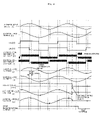
- FIG. 3 shows an input signal, a detection control signal, a coil difference voltage, a load current, and an induced voltage of each phase and further shows the rotation speed of a rotor and the logic of stop determination output according to the embodiment.
- the detection control unit ( 310 ) transmits a command for obtaining a high impedance output for a certain time to the output unit ( 120 , 220 ) of the phase to be detected.
- the current of the coil is regenerated as has been discussed, so that the current becomes zero.
- the current value of the other phase keeps changing and the rotor keeps rotating by the inertia of the rotor in microstep driving.
- a distance between the permanent magnet of the rotor and the coil changes and an induced voltage is generated.
- the induced voltage generates a voltage having a sinusoidal wave with the same period as an energization period in synchronization with the phase of the rotor.
- a distance between the permanent magnet of the rotor and the coil does not change. Thus the induced voltage is not generated.
- an induced voltage is generated in a different direction from the direction of an actual induced voltage.
- One of an A-phase induced voltage detection unit ( 140 ) and a B-phase induced voltage detection unit ( 240 ) detects the generation of an induced voltage.
- the detection control unit ( 310 ) instructs the induced voltage detection unit ( 140 , 240 ) of the phase to be detected, about the timing of detection and a direction along which the induced voltage is generated.
- the induced voltage detection unit ( 140 , 240 ) detects the direction along which the induced voltage is generated and detects whether or not the absolute value of the induced voltage exceeds a predetermined threshold value, and outputs the result to a stop determination unit ( 320 ).
- the stop determination unit ( 320 ) updates a stop determination result in each energization period of 90°.
- the result of one of the induced voltage detection units ( 140 , 240 ) is updated every time the detection control signal is generated, so that a determination result can be obtained with high responsiveness.
- the stop determination result is updated at shorter intervals.
- a circuit size can be reduced by reducing the number of detected phases and increasing an interval between updates.
- a determination about whether the rotor is stopped or rotated is outputted based on a plurality of results from an induced voltage detection unit. For example, when it is determined that the rotor is stopped, the state is recorded. When it is determined again that the rotor is stopped at the subsequent determination update in which a rotation is kept, a stop signal is not outputted to a stop determination output until it is determined that the rotor is stopped for two consecutive times. The stop signal can be outputted also after more determinations or when at least a predetermined number of stops are determined in a period.
- the plurality of results from the induced voltage detection unit make it possible to achieve stop determination with higher reliability.
- an output current at the zero cross has the largest induced voltage and is the most effective against noise and an induced voltage resonance reduced by resonance.
- the amplitude of the generated induced voltage is substantially proportionate to the number of revolutions. The larger number of revolutions, the higher induced voltage.
- the threshold value is set in consideration of the number of revolutions and an allowance for a phase shift.
- a high impedance output can be obtained when the output current is zero, the distortions of waveforms can be minimized and efficient driving can be performed.
- detection has to be performed with the high impedance until the current is completely regenerated.
- a longer time is necessary for the high impedance. Switching to the high impedance at the current zero cross can shorten a high impedance time, reduce a non-conducting time, and suppress the distortions of an output waveform.
- FIG. 4 is an explanatory drawing showing the second embodiment of the present invention.
- An A-phase current zero-cross detection unit ( 131 ) and a B-phase current zero-cross detection unit ( 231 ) which detect a current zero cross according to a clipped voltage during regeneration are connected to one output of an A-phase motor coil and one output of a B-phase motor coil, respectively.
- the A-phase current zero-cross detection unit ( 131 ) and the B-phase current zero-cross detection unit ( 231 ) output detection results of zero cross to a detection control unit ( 310 ).
- the detection control unit performs, as in the embodiment of FIG. 1 , a sequence for detecting an induced voltage.
- FIG. 1 a sequence for detecting an induced voltage.
- FIG. 5 is an explanatory drawing of the A-phase current zero-cross detection unit ( 131 ) and the B-phase current zero-cross detection unit ( 231 ).
- PWM driving of both chopping method is performed in an H-bridge circuit shown in FIG. 5
- outputs Va and Vb connected to both ends of a coil ( 31 ) alternately repeat L output and H output.
- the coil is energized.
- an output current is smoothed by performing PMW driving with a sufficiently shorter period than a time constant determined by the inductance and the resistance value of the coil of a motor.
- the smoothed current has a phase delayed from the phase of the mean value of an output voltage by the time constant determined by the inductance and the resistance value of the coil.
- FIG. 6 shows the output waveform of the power transistor around the current zero cross, the output waveforms of comparators, and the output signal of current zero-cross stop determination.
- the current zero-cross detection unit monitors Va and Vb and a clamping voltage generated by regeneration is detected by comparators ( 61 , 62 ).
- the comparators ( 61 , 62 ) for detecting regeneration output output results Vc and Vd to an R-S flip-flop ( 63 ). By changing the direction of current, a detection output is switched from the comparator ( 61 ) on the power supply to the comparator ( 62 ) on the ground.
- An output Ve of the R-S flip-flop ( 63 ) indicates the direction of current, and rising and falling edges indicate the timing of switching directions.
- the current zero-cross detection unit outputs the timing of zero cross to the detection control unit, and the detection control unit ( 310 ) performs the sequence for detecting an induced voltage as in the embodiment of FIG. 1 .
- FIG. 7 is an explanatory drawing showing the third embodiment of the present invention.
- reference numeral 300 denotes a two-phase bipolar stepping motor.
- An A-phase output unit ( 120 ) and a B-phase output unit ( 220 ) drive power transistors so as to output a current obtained by multiplying the values of the A-phase input signal and the B-phase input signal by a optionally set gain.
- FIG. 8 shows, according to the third embodiment of the present invention, an input signal of each phase, an input threshold value of each phase, the output signal of the comparator of each phase, a voltage difference between coil terminals, a load current, an induced voltage, the rotation speed of a rotor, and the logic of stop determination output.
- the A-phase input signal and an A-phase input threshold value are compared with each other by an A-phase comparator ( 150 ) and are outputted as a binary output signal ( 150 a ).
- a B-phase input threshold value is compared by a B-phase comparator ( 250 ) and is outputted as a binary output signal ( 250 a ).
- the two output signals ( 150 a , 250 a ) are inputted to a detection control unit ( 310 ).
- a signal is transmitted to have a high-impedance output for a certain time from the output unit ( 120 , 220 ) of a phase to be detected.
- a previous input command comes close to zero at this moment and the current of a coil comes close to zero, though a small amount of the current remains.
- the current of the coil is regenerated and completely becomes zero in a short time.
- FIG. 9A shows, around an input zero cross, the waveforms of the input signal, a load current, and a difference in voltage between an output Va terminal and an output Vb terminal when a high-impedance output is obtained at the input zero cross according to a current driving method.
- the driving method uses output current feedback, an input command and an output current are in phase with each other.
- the timing of the input zero cross and the timing of the zero cross of output current are synchronized with each other.
- the highest induced voltage can be detected and thus a rotating state and a non-rotating state can be easily distinguished from each other.
- the zero cross of output current is not directly detected.
- the timing of the zero cross of output current is obtained based on the input value obtained through feedback. Consequently, the detection can be performed in a short time and the same effects as the configurations of FIGS. 1 and 4 can be obtained.
- FIG. 9B shows, around the input zero cross, the waveforms of the input signal, a load current, and a difference in voltage between the output Va terminal and the output Vb terminal when a high-impedance output is obtained at the input zero cross in voltage driving.
- the phase of current is delayed by the inductance of a coil ( 31 ) and the time constant of a resistance component.
- an amount of current passing through the coil ( 31 ) is not sufficiently small and a time period until a load current becomes zero by regeneration has to be sufficiently long as compared with current feedback. Insufficient high-impedance time cannot enable accurate measurements but a long high-impedance section distorts an energization waveform, so that it is impossible to reduce vibrations and noise and prevent loss of synchronization.
- FIG. 10 is an explanatory drawing showing the fourth embodiment of the present invention.
- the output signals (Vg, Vh) of an A-phase comparator and a B-phase comparator are respectively inputted to an A-phase signal delay unit ( 160 ) and a B-phase signal delay unit ( 260 ) which can delay the signals by a predetermined time, and delay results are inputted to a detection control unit ( 310 ).
- the phase of a current waveform is delayed by the inductance of a motor and a resistance component and the timing of the zero cross of output current is considerably delayed by the phase delay.
- FIG. 9B the phase of a current waveform is delayed by the inductance of a motor and a resistance component and the timing of the zero cross of output current is considerably delayed by the phase delay.
- FIG. 10 by delaying the signals in the A-phase signal delay unit ( 160 ) and the B-phase signal delay unit ( 260 ), detection is performed at the zero cross of output current.
- FIG. 11 shows the signal timing of Vg, Vh, Vi and Vj and the relationship between an input/output and an induced voltage.
- FIG. 12 is an enlarged view around the zero cross of an input signal.
- FIG. 13 is an explanatory drawing showing the fifth embodiment of the present invention.
- the timing delay of an input zero cross can be adjusted in response to a signal from the inside or the outside of a circuit, so that it is possible to respond to fluctuations in delay time.
- the delay time changes with surrounding conditions such as a load of a coil and an input waveform.
- FIG. 14 is an explanatory drawing showing the sixth embodiment of the present invention. Discharge by the regeneration of a load current is not always completely switched at zero current, and a discharge time of current is actually necessary.
- the load of a coil is changed by changing stepping motors or when surrounding conditions are changed, the discharge time fluctuates.
- a state is optimized by changing a high-impedance time in response to a signal from the inside or outside of a circuit. This configuration can prevent erroneous detection which is caused by a residual coil current because of an insufficient high-impedance time as shown in FIG. 9B .
- the high-impedance time is longer than necessary, a driving waveform with few distortions can be obtained by eliminating an excessive high-impedance time.
- the present invention can reduce the possibility of noise, vibrations, and loss of synchronization, efficiently rotate a stepping motor, and determine whether a rotor is stopped or not.
- the present invention is particularly applicable to a driver of a stepping motor for determining whether an optical pickup is stopped or not in an optical disk device. Further, the present invention is applicable to a driver of a stepping motor as a resetting operation to the zero position of an analog instrument and the like.
Landscapes
- Engineering & Computer Science (AREA)
- Power Engineering (AREA)
- Control Of Stepping Motors (AREA)
Priority Applications (1)
| Application Number | Priority Date | Filing Date | Title |
|---|---|---|---|
| US13/373,241 US8362734B2 (en) | 2007-09-10 | 2011-11-09 | Stepping motor driver |
Applications Claiming Priority (2)
| Application Number | Priority Date | Filing Date | Title |
|---|---|---|---|
| JP2007-233542 | 2007-09-10 | ||
| JP2007233542A JP2009065806A (ja) | 2007-09-10 | 2007-09-10 | ステッピングモータ駆動装置及びステッピングモータ駆動方法 |
Related Child Applications (1)
| Application Number | Title | Priority Date | Filing Date |
|---|---|---|---|
| US13/373,241 Continuation US8362734B2 (en) | 2007-09-10 | 2011-11-09 | Stepping motor driver |
Publications (2)
| Publication Number | Publication Date |
|---|---|
| US20090066278A1 US20090066278A1 (en) | 2009-03-12 |
| US8072177B2 true US8072177B2 (en) | 2011-12-06 |
Family
ID=40431145
Family Applications (2)
| Application Number | Title | Priority Date | Filing Date |
|---|---|---|---|
| US12/206,096 Expired - Fee Related US8072177B2 (en) | 2007-09-10 | 2008-09-08 | Stepping motor driver |
| US13/373,241 Expired - Fee Related US8362734B2 (en) | 2007-09-10 | 2011-11-09 | Stepping motor driver |
Family Applications After (1)
| Application Number | Title | Priority Date | Filing Date |
|---|---|---|---|
| US13/373,241 Expired - Fee Related US8362734B2 (en) | 2007-09-10 | 2011-11-09 | Stepping motor driver |
Country Status (3)
| Country | Link |
|---|---|
| US (2) | US8072177B2 (ja) |
| JP (1) | JP2009065806A (ja) |
| CN (1) | CN101388635A (ja) |
Cited By (10)
| Publication number | Priority date | Publication date | Assignee | Title |
|---|---|---|---|---|
| US20100164426A1 (en) * | 2008-12-25 | 2010-07-01 | Keishi Honmura | Stepping motor control circuit and analogue electronic watch |
| US20100188036A1 (en) * | 2009-01-28 | 2010-07-29 | Kosaku Hioki | Driver circuit |
| US20100238768A1 (en) * | 2009-03-18 | 2010-09-23 | Kazuo Kato | Stepping motor control circuit and analogue electronic timepiece |
| US20100254226A1 (en) * | 2009-04-02 | 2010-10-07 | Kenji Ogasawara | Stepping motor control circuit and analog electronic watch |
| US20110110138A1 (en) * | 2009-05-01 | 2011-05-12 | Board Of Regents, The University Of Texas System | Methods and Systems for Phase Current Reconstruction of AC Drive Systems |
| US20130229139A1 (en) * | 2012-03-02 | 2013-09-05 | Minebea Co., Ltd. | Motor control device and out-of-step detecting method of stepping motor |
| US8736298B2 (en) | 2011-10-26 | 2014-05-27 | Semiconductor Components Industries, Llc | Method for detecting a step loss condition |
| US10516347B1 (en) * | 2019-03-27 | 2019-12-24 | Omron Automotive Electronics Co., Ltd. | Load detection method and apparatus |
| US11264926B2 (en) * | 2019-03-13 | 2022-03-01 | Rohm Co., Ltd. | Driving circuit and method for stepping motor |
| US20220294318A1 (en) * | 2019-12-05 | 2022-09-15 | Rohm Co., Ltd. | Circuit and method for driving stepping motor |
Families Citing this family (29)
| Publication number | Priority date | Publication date | Assignee | Title |
|---|---|---|---|---|
| US8063603B2 (en) * | 2008-01-22 | 2011-11-22 | Cypress Semiconductor Corporation | System and method for using a stepper motor as a rotary sensor |
| DE102010000286B4 (de) * | 2009-02-05 | 2019-05-23 | Denso Corporation | Anzeigeinstrument für ein Fahrzeug |
| US8058894B2 (en) * | 2009-03-31 | 2011-11-15 | Semiconductor Components Industries, Llc | Method for detecting a fault condition |
| JP2011010394A (ja) * | 2009-06-23 | 2011-01-13 | Sanyo Electric Co Ltd | ドライバ回路 |
| JP5697320B2 (ja) * | 2009-09-18 | 2015-04-08 | セミコンダクター・コンポーネンツ・インダストリーズ・リミテッド・ライアビリティ・カンパニー | ドライバ回路 |
| JP5591507B2 (ja) * | 2009-09-18 | 2014-09-17 | セミコンダクター・コンポーネンツ・インダストリーズ・リミテッド・ライアビリティ・カンパニー | ドライバ回路 |
| JP5591508B2 (ja) * | 2009-09-18 | 2014-09-17 | セミコンダクター・コンポーネンツ・インダストリーズ・リミテッド・ライアビリティ・カンパニー | ドライバ回路 |
| JP5701503B2 (ja) * | 2009-12-28 | 2015-04-15 | セミコンダクター・コンポーネンツ・インダストリーズ・リミテッド・ライアビリティ・カンパニー | モータ駆動回路 |
| JP5491207B2 (ja) * | 2010-01-13 | 2014-05-14 | キヤノン株式会社 | ステッピングモータの駆動装置 |
| JP5705457B2 (ja) * | 2010-05-13 | 2015-04-22 | セミコンダクター・コンポーネンツ・インダストリーズ・リミテッド・ライアビリティ・カンパニー | リニア振動モータの駆動制御回路 |
| JP5432057B2 (ja) | 2010-05-13 | 2014-03-05 | セミコンダクター・コンポーネンツ・インダストリーズ・リミテッド・ライアビリティ・カンパニー | リニア振動モータの駆動制御回路 |
| JP5786283B2 (ja) * | 2010-06-04 | 2015-09-30 | 株式会社リコー | モータ制御装置、画像形成装置及びモータ制御方法 |
| JP5641819B2 (ja) * | 2010-08-24 | 2014-12-17 | キヤノン株式会社 | 画像形成装置 |
| CN102374328B (zh) * | 2010-08-27 | 2013-10-23 | 杭州三花研究院有限公司 | 一种电子膨胀阀及其步进电机在汽车空调中的应用 |
| JP5967662B2 (ja) * | 2010-09-17 | 2016-08-10 | マーベル ワールド トレード リミテッド | モータ制御のための逆起電力検出 |
| JP5321614B2 (ja) * | 2011-02-28 | 2013-10-23 | 株式会社デンソー | 回転機の制御装置 |
| DE102011017517A1 (de) * | 2011-04-26 | 2012-10-31 | Robert Bosch Gmbh | Verfahren zur sensorlosen Kommutierungserkennung von elektronisch kommutierten Elektromotoren |
| JP2013074751A (ja) | 2011-09-28 | 2013-04-22 | Semiconductor Components Industries Llc | ステッピングモータの駆動回路 |
| JP5856438B2 (ja) * | 2011-11-01 | 2016-02-09 | 株式会社日立製作所 | 電力変換装置 |
| TWI441444B (zh) * | 2011-12-26 | 2014-06-11 | Anpec Electronics Corp | 調整馬達轉速之方法及可調整轉速之馬達驅動電路 |
| JP6162513B2 (ja) * | 2012-09-07 | 2017-07-12 | セイコーインスツル株式会社 | ステッピングモータ制御回路、ムーブメント及びアナログ電子時計 |
| JP6100561B2 (ja) * | 2013-02-28 | 2017-03-22 | ローム株式会社 | モータ駆動回路、およびその駆動方法、それを用いた電子機器 |
| WO2014181936A1 (en) | 2013-05-08 | 2014-11-13 | Samsung Electronics Co., Ltd. | Image forming apparatus, motor control apparatus, and method of controlling a motor |
| JP6149532B2 (ja) * | 2013-06-19 | 2017-06-21 | 富士電機株式会社 | ステッピングモータ駆動装置 |
| JP6265826B2 (ja) * | 2014-04-30 | 2018-01-24 | 川崎重工業株式会社 | 単相系統に接続される電力変換装置 |
| JP6423745B2 (ja) * | 2015-03-19 | 2018-11-14 | カシオ計算機株式会社 | ステッピングモータ駆動装置および時計 |
| DE102018126954A1 (de) * | 2018-10-29 | 2020-04-30 | Trinamic Motion Control Gmbh & Co. Kg | Verfahren und Schaltungsanordnung zur sensorlosen Lasterfassung bei Schrittmotoren |
| US10824130B2 (en) * | 2019-01-31 | 2020-11-03 | Texas Instruments Incorporated | Stepper motor |
| CN110989500B (zh) * | 2019-12-31 | 2023-03-10 | 苏州大学 | 快刀伺服车削的驱动控制方法、装置、设备及存储介质 |
Citations (12)
| Publication number | Priority date | Publication date | Assignee | Title |
|---|---|---|---|---|
| US5708578A (en) * | 1995-07-19 | 1998-01-13 | Stoddard; Robert J. | PWM inductive load bridge driver for dynamically mixing four and two quadrant chopping during PWM period off time |
| US5886484A (en) * | 1995-05-23 | 1999-03-23 | Sgs-Thomson Microelectronics, S.R.L. | Masking of switching noise in controlling a "H" bridge |
| US6066930A (en) | 1996-09-03 | 2000-05-23 | Shindengen Electric Manufacturing Co., Ltd. | Synchronous driving method for inductive load and synchronous controller for H-bridge circuit |
| US6196650B1 (en) * | 1994-10-17 | 2001-03-06 | Sony Corporation | Sensorless motor driving circuit having a comparative phase lock loop arrangement |
| US6208112B1 (en) * | 1998-12-28 | 2001-03-27 | Grundfos A/S | Method for controlling a voltage/frequency converter controlled single-phase or polyphase electric motor |
| US6218795B1 (en) * | 1998-12-17 | 2001-04-17 | Matsushita Electric Industrial Co., Ltd. | Rotor magnetic pole position detection device |
| US20030076068A1 (en) | 2000-01-11 | 2003-04-24 | Charles Pollock | Load angle determination for electrical motors |
| JP2003186792A (ja) | 2001-12-14 | 2003-07-04 | Kengo Inoue | メッセージ表示方法,そのサーバ及びクライアント |
| JP2005027370A (ja) | 2003-06-30 | 2005-01-27 | Seiko Precision Inc | ステッピングモータにおけるロータの状態検出装置及び方法 |
| US6919763B2 (en) * | 2002-08-30 | 2005-07-19 | Stmicroelectronics S.R.L. | Transconductance amplifier for inductive loads and method for driving inductive loads |
| US6956351B2 (en) | 2003-06-25 | 2005-10-18 | Yazaki Corporation | Driving device for stepping motor |
| US20070159122A1 (en) * | 2006-01-06 | 2007-07-12 | Stmicroelectronics, Inc. | Universal motor speed controller |
Family Cites Families (5)
| Publication number | Priority date | Publication date | Assignee | Title |
|---|---|---|---|---|
| US4518904A (en) * | 1984-01-25 | 1985-05-21 | Rodime Plc | Stepper motor control for data disk system |
| US5264770A (en) * | 1992-03-12 | 1993-11-23 | Coutu David J | Stepper motor driver circuit |
| US5598071A (en) * | 1994-07-11 | 1997-01-28 | Seagate Technology | Method for starting and commutating a permanent-magnet direct current motor having a single phase winding |
| US5847535A (en) * | 1996-01-31 | 1998-12-08 | Parker-Hannifin Corporation | Active electronic damping for step motor |
| US7352150B2 (en) * | 2005-07-08 | 2008-04-01 | Matsushita Electric Industrial Co., Ltd. | Stepping motor driving apparatus and stepping motor driving method |
-
2007
- 2007-09-10 JP JP2007233542A patent/JP2009065806A/ja not_active Withdrawn
-
2008
- 2008-09-08 US US12/206,096 patent/US8072177B2/en not_active Expired - Fee Related
- 2008-09-09 CN CNA2008101608907A patent/CN101388635A/zh active Pending
-
2011
- 2011-11-09 US US13/373,241 patent/US8362734B2/en not_active Expired - Fee Related
Patent Citations (12)
| Publication number | Priority date | Publication date | Assignee | Title |
|---|---|---|---|---|
| US6196650B1 (en) * | 1994-10-17 | 2001-03-06 | Sony Corporation | Sensorless motor driving circuit having a comparative phase lock loop arrangement |
| US5886484A (en) * | 1995-05-23 | 1999-03-23 | Sgs-Thomson Microelectronics, S.R.L. | Masking of switching noise in controlling a "H" bridge |
| US5708578A (en) * | 1995-07-19 | 1998-01-13 | Stoddard; Robert J. | PWM inductive load bridge driver for dynamically mixing four and two quadrant chopping during PWM period off time |
| US6066930A (en) | 1996-09-03 | 2000-05-23 | Shindengen Electric Manufacturing Co., Ltd. | Synchronous driving method for inductive load and synchronous controller for H-bridge circuit |
| US6218795B1 (en) * | 1998-12-17 | 2001-04-17 | Matsushita Electric Industrial Co., Ltd. | Rotor magnetic pole position detection device |
| US6208112B1 (en) * | 1998-12-28 | 2001-03-27 | Grundfos A/S | Method for controlling a voltage/frequency converter controlled single-phase or polyphase electric motor |
| US20030076068A1 (en) | 2000-01-11 | 2003-04-24 | Charles Pollock | Load angle determination for electrical motors |
| JP2003186792A (ja) | 2001-12-14 | 2003-07-04 | Kengo Inoue | メッセージ表示方法,そのサーバ及びクライアント |
| US6919763B2 (en) * | 2002-08-30 | 2005-07-19 | Stmicroelectronics S.R.L. | Transconductance amplifier for inductive loads and method for driving inductive loads |
| US6956351B2 (en) | 2003-06-25 | 2005-10-18 | Yazaki Corporation | Driving device for stepping motor |
| JP2005027370A (ja) | 2003-06-30 | 2005-01-27 | Seiko Precision Inc | ステッピングモータにおけるロータの状態検出装置及び方法 |
| US20070159122A1 (en) * | 2006-01-06 | 2007-07-12 | Stmicroelectronics, Inc. | Universal motor speed controller |
Cited By (16)
| Publication number | Priority date | Publication date | Assignee | Title |
|---|---|---|---|---|
| US20100164426A1 (en) * | 2008-12-25 | 2010-07-01 | Keishi Honmura | Stepping motor control circuit and analogue electronic watch |
| US20100188036A1 (en) * | 2009-01-28 | 2010-07-29 | Kosaku Hioki | Driver circuit |
| US8497653B2 (en) * | 2009-01-28 | 2013-07-30 | Semiconductor Components Industries, Llc | Driver circuit for driving a stepping motor |
| US9356545B2 (en) | 2009-01-28 | 2016-05-31 | Semiconductor Components Industries, Llc | Driver circuit and method |
| US20100238768A1 (en) * | 2009-03-18 | 2010-09-23 | Kazuo Kato | Stepping motor control circuit and analogue electronic timepiece |
| US20100254226A1 (en) * | 2009-04-02 | 2010-10-07 | Kenji Ogasawara | Stepping motor control circuit and analog electronic watch |
| US20110110138A1 (en) * | 2009-05-01 | 2011-05-12 | Board Of Regents, The University Of Texas System | Methods and Systems for Phase Current Reconstruction of AC Drive Systems |
| US8248829B2 (en) * | 2009-05-01 | 2012-08-21 | Board Of Regents, The University Of Texas System | Methods and systems for phase current reconstruction of AC drive systems |
| US8736298B2 (en) | 2011-10-26 | 2014-05-27 | Semiconductor Components Industries, Llc | Method for detecting a step loss condition |
| US8896257B2 (en) * | 2012-03-02 | 2014-11-25 | Minebea Co., Ltd. | Motor control device and out-of-step detecting method of stepping motor |
| US20130229139A1 (en) * | 2012-03-02 | 2013-09-05 | Minebea Co., Ltd. | Motor control device and out-of-step detecting method of stepping motor |
| DE102013101976B4 (de) | 2012-03-02 | 2023-03-02 | Minebea Mitsumi Inc. | Motorsteuerung und Verfahren zum Erfassen von Schrittfehlern eines Schrittmotors |
| US11264926B2 (en) * | 2019-03-13 | 2022-03-01 | Rohm Co., Ltd. | Driving circuit and method for stepping motor |
| US10516347B1 (en) * | 2019-03-27 | 2019-12-24 | Omron Automotive Electronics Co., Ltd. | Load detection method and apparatus |
| US20220294318A1 (en) * | 2019-12-05 | 2022-09-15 | Rohm Co., Ltd. | Circuit and method for driving stepping motor |
| US12088155B2 (en) * | 2019-12-05 | 2024-09-10 | Rohm Co., Ltd. | Circuit and method for driving stepping motor |
Also Published As
| Publication number | Publication date |
|---|---|
| JP2009065806A (ja) | 2009-03-26 |
| US8362734B2 (en) | 2013-01-29 |
| US20120056574A1 (en) | 2012-03-08 |
| CN101388635A (zh) | 2009-03-18 |
| US20090066278A1 (en) | 2009-03-12 |
Similar Documents
| Publication | Publication Date | Title |
|---|---|---|
| US8072177B2 (en) | Stepping motor driver | |
| JP2009065806A5 (ja) | ||
| KR101748188B1 (ko) | 스텝 로스 조건을 검출하기 위한 방법 | |
| US7298106B2 (en) | Motor driving device and motor driving method | |
| US8106612B2 (en) | Brushless motor control device and brushless motor control method | |
| US8093847B2 (en) | Motor drive circuit, method, and disc device using the same | |
| JP2008005632A (ja) | モータ駆動装置及びモータ駆動方法並びにディスク駆動装置 | |
| JP2007236062A (ja) | モータ駆動装置及びモータ駆動方法並びにディスク駆動装置 | |
| US8159176B2 (en) | Motor driving device | |
| US8466648B2 (en) | Motor control device and out-of-step detecting method | |
| US20070164694A1 (en) | Method for determining the back electromotive force induced in a voice-coil motor driven in discontinuous mode | |
| CN112088486A (zh) | 马达的操作模式控制 | |
| WO2011073742A2 (en) | Stepper motor stall detection | |
| US7906928B2 (en) | Feed motor lock detection device | |
| JP5464793B2 (ja) | モータ駆動装置 | |
| US9571021B2 (en) | Motor control device and method for detecting out-of-step | |
| US7453230B1 (en) | Synchronization circuit and method of performing synchronization | |
| JP5406455B2 (ja) | 送りモータのロック検出装置 | |
| US8416664B1 (en) | Driving circuit for stepping motor | |
| JP2013031294A (ja) | モータ制御装置 | |
| US20120104985A1 (en) | Stepping motor drive unit | |
| US8736298B2 (en) | Method for detecting a step loss condition | |
| US12015363B2 (en) | Motor drive circuit, motor system, and electric device | |
| JP4070280B2 (ja) | ステッピングモータの脱調検出装置 | |
| JP5250746B2 (ja) | モータ駆動装置 |
Legal Events
| Date | Code | Title | Description |
|---|---|---|---|
| AS | Assignment |
Owner name: PANASONIC CORPORATION, JAPAN Free format text: ASSIGNMENT OF ASSIGNORS INTEREST;ASSIGNOR:ARISAWA, DAIJIRO;REEL/FRAME:021680/0270 Effective date: 20080901 |
|
| STCF | Information on status: patent grant |
Free format text: PATENTED CASE |
|
| FEPP | Fee payment procedure |
Free format text: PAYOR NUMBER ASSIGNED (ORIGINAL EVENT CODE: ASPN); ENTITY STATUS OF PATENT OWNER: LARGE ENTITY |
|
| FPAY | Fee payment |
Year of fee payment: 4 |
|
| FEPP | Fee payment procedure |
Free format text: MAINTENANCE FEE REMINDER MAILED (ORIGINAL EVENT CODE: REM.); ENTITY STATUS OF PATENT OWNER: LARGE ENTITY |
|
| LAPS | Lapse for failure to pay maintenance fees |
Free format text: PATENT EXPIRED FOR FAILURE TO PAY MAINTENANCE FEES (ORIGINAL EVENT CODE: EXP.); ENTITY STATUS OF PATENT OWNER: LARGE ENTITY |
|
| STCH | Information on status: patent discontinuation |
Free format text: PATENT EXPIRED DUE TO NONPAYMENT OF MAINTENANCE FEES UNDER 37 CFR 1.362 |
|
| FP | Lapsed due to failure to pay maintenance fee |
Effective date: 20191206 |