US8005573B2 - Control device for legged mobile robot - Google Patents
Control device for legged mobile robot Download PDFInfo
- Publication number
- US8005573B2 US8005573B2 US10/562,168 US56216805A US8005573B2 US 8005573 B2 US8005573 B2 US 8005573B2 US 56216805 A US56216805 A US 56216805A US 8005573 B2 US8005573 B2 US 8005573B2
- Authority
- US
- United States
- Prior art keywords
- reaction force
- floor reaction
- robot
- gait
- motion
- Prior art date
- Legal status (The legal status is an assumption and is not a legal conclusion. Google has not performed a legal analysis and makes no representation as to the accuracy of the status listed.)
- Expired - Fee Related, expires
Links
Images


Classifications
-
- B—PERFORMING OPERATIONS; TRANSPORTING
- B62—LAND VEHICLES FOR TRAVELLING OTHERWISE THAN ON RAILS
- B62D—MOTOR VEHICLES; TRAILERS
- B62D57/00—Vehicles characterised by having other propulsion or other ground- engaging means than wheels or endless track, alone or in addition to wheels or endless track
- B62D57/02—Vehicles characterised by having other propulsion or other ground- engaging means than wheels or endless track, alone or in addition to wheels or endless track with ground-engaging propulsion means, e.g. walking members
- B62D57/032—Vehicles characterised by having other propulsion or other ground- engaging means than wheels or endless track, alone or in addition to wheels or endless track with ground-engaging propulsion means, e.g. walking members with alternately or sequentially lifted supporting base and legs; with alternately or sequentially lifted feet or skid
-
- B—PERFORMING OPERATIONS; TRANSPORTING
- B25—HAND TOOLS; PORTABLE POWER-DRIVEN TOOLS; MANIPULATORS
- B25J—MANIPULATORS; CHAMBERS PROVIDED WITH MANIPULATION DEVICES
- B25J5/00—Manipulators mounted on wheels or on carriages
-
- B—PERFORMING OPERATIONS; TRANSPORTING
- B25—HAND TOOLS; PORTABLE POWER-DRIVEN TOOLS; MANIPULATORS
- B25J—MANIPULATORS; CHAMBERS PROVIDED WITH MANIPULATION DEVICES
- B25J13/00—Controls for manipulators
Definitions
- the present invention relates to a control device suited to walking and also running of a legged mobile robot.
- gait since the Chinese characters for “gait” include a character meaning “walking,” the gait tends to be misinterpreted that the definition thereof is limited to walking. However, “gait” originally presents a concept that includes running, as it is used as a term indicating a running mode of a horse, such as “trot.”
- a traveling mode that has an instant at which all legs are simultaneously floating is usually defined as running. This definition, however, does not necessarily make it possible to clearly distinguish between walking and running. For instance, most humans have instants at which all legs float at the same time in fast jogging, whereas many humans have one of the legs always in contact with the ground in slow jogging. It is somehow perceptually unreasonable to define fast jogging as running and slow jogging as walking.
- FIG. 51 shows a pattern of a vertical body position and a floor reaction force vertical component (a sum of floor reaction force vertical components acting on right and left legs) in typical running
- FIG. 52 shows a pattern of a vertical body position and a floor reaction force vertical component in typical walking.
- a vertical body position/velocity means a vertical position of a representative point of a body and a velocity thereof.
- a horizontal body position/velocity means a horizontal position of a representative point of the body and a velocity thereof.
- a vertical body position/velocity and a horizontal body position/velocity together will be referred to as body position/velocity.
- the “floor reaction force vertical component” should be described as “translational floor reaction force vertical component” to distinguish it from a moment component about a vertical axis of a floor reaction force; however, the term is too long, so that the term “translational” will be omitted.
- the “translational floor reaction force horizontal component” will be described as “floor reaction force horizontal component,” omitting “translational.”
- a floor reaction force remains relatively constant in walking, whereas it considerably varies in running, the floor reaction force reaching its maximum at the moment the body passes over a supporting leg. Needless to say, the floor reaction force is zero at the instant when all legs are simultaneously floating. More detailed observation reveals that a floor reaction force of a magnitude that is substantially proportional to a compression amount of the supporting leg is generated while running. In other words, it may be said that the legs are used like springs to jump for traveling while running.
- Slow jogging has the same body vertical motion phase as that of typical running. In addition, slow jogging frequently has no instants at which all legs are simultaneously floating; however, even in this case, a floor reaction force reaches substantially zero, although not completely zero, at an instant when a supporting leg and an idle leg are switched.
- running may be defined as a traveling mode in which the floor reaction force becomes zero or substantially zero at the instant a supporting leg is switched
- walking may be defined as a traveling mode (a floor reaction force vertical component remaining relatively constant) other than that.
- the present applicant has also proposed the following art in, for example, Japanese Unexamined Patent Application Publication No. 5-337849.
- an inclination error of a robot the difference between an actual inclination angle with respect to the vertical direction of the body of the robot and an inclination angle of a desired gait
- an actual ZMP is shifted and a moment in a posture restoring direction is generated about a desired ZMP within a permissible range, and then the motion of the desired gait is determined so as to generate a moment about the desired ZMP on a model used for generating the desired gait.
- intentionally generating a moment on a model makes it possible to provide an effect equivalent to generating a moment in the posture restoring direction on an actual robot.
- spin refers to a state in which a yaw angular (a rotational angle about a vertical axis) velocity of an actual robot deviates from a desired yaw angular velocity.
- a floor reaction force vertical component is always substantially equivalent to a robot's own weight, thus providing a higher limit of a frictional force (i.e., the floor reaction force moment vertical component). This makes it difficult for a spin to occur.
- the moment vertical component of a desired gait is substantially zero.
- the arms will be also briskly swung.
- the mass of an arm in a human-type robot is smaller than the mass of a leg. Accordingly, it is necessary to swing arms more briskly than legs in order to fully cancel a moment vertical component.
- an object of the present invention is to provide a control device which solves the problems described above and which is capable of generating a further ideal gait regardless of gait types, such as walking and running, and a friction condition of a floor surface.
- an object of the present invention is to provide a control device capable of operating a robot by gaits that enable the robot to prevent spinning or falling from a spin, while maintaining a stable posture state in a yaw direction of the robot by considering a limit of a moment vertical component of a frictional force between the robot and a floor surface.
- Another object is to provide a control device capable of operating a robot by a gait motion pattern that satisfies a dynamic balance condition even in a leg-floating period or even if the limit of a moment vertical component of a frictional force is extremely low.
- Still another object is to prevent lateral asymmetry of a desired gait from increasing so as to secure continuity of a motion.
- a control device of a legged mobile robot adapted to sequentially determine instantaneous values of a desired motion and a desired floor reaction force of a legged mobile robot that travels by moving legs extended from its body by using a dynamic model that expresses a relationship between at least a motion of the robot and a floor reaction force, and also to control an operation of the robot at the same time so as to make the robot follow the Determined instantaneous values of the desired motion and the desired floor reaction force, comprising:
- a permissible range setting means for setting a permissible range of a restriction object amount, the restriction object amount being a vertical component of a floor reaction force moment or a component of the floor reaction force moment in floor surface normal line direction to be applied to a robot in operation, following the desired motion and the desired floor reaction force;
- a desired instantaneous value determining means for determining, on the basis of at least a difference between a desired state amount related to a posture of the robot about a vertical axis or about a floor surface normal line axis and an actual state amount of the robot and the permissible range, instantaneous values of the desired motion and the desired floor reaction force such that a deviation between a floor reaction force moment balancing with the desired motion on the dynamic model and a floor reaction force moment of the desired floor reaction force approximates the difference to zero, while having the restriction object amount, which is associated with the desired floor reaction force, fall within the permissible range.
- instantaneous values of the desired motion and the desired floor reaction force are determined such that the deviation between a floor reaction force moment balancing with the desired motion on the dynamic model and a floor reaction force moment of the desired floor reaction force approximates the above difference to zero, while setting a restriction object amount, which is associated with the desired floor reaction force, to fall within the permissible range.
- a restriction object amount such as a floor reaction force moment vertical component applied to an actual robot
- a restriction object amount can be set to fall within a permissible range, while bringing a state amount related to the posture of the robot about a vertical axis or a floor surface normal axis (hereinafter referred to as a posture state amount in the yaw direction) close to a desired state amount, that is, a desired posture state amount in the yaw direction in a desired motion (while approximating the difference to zero).
- a posture state amount in the yaw direction a state amount related to the posture of the robot about a vertical axis or a floor surface normal axis
- the desired instantaneous value determining means includes a means for determining a compensating floor reaction force moment, which is an additional floor reaction force moment for bringing a difference to zero according to the difference, and a means for determining a correction amount of a predetermined provisional instantaneous value such that the restriction object amount does not exceed the permissible range on the basis of at least a floor reaction force moment that balances with the predetermined provisional instantaneous value of the desired motion on the dynamic model and the compensating floor reaction force moment, wherein the provisional instantaneous value is corrected on the basis of the determined correction amount so as to determine the instantaneous value of the desired motion (a second invention).
- the correction amount of a predetermined provisional instantaneous value is determined on the basis of a floor reaction force moment that is produced on the dynamic model by the predetermined provisional instantaneous value of a desired motion (the floor reaction force moment balancing a desired motion) and a compensating floor reaction force moment for approximating the difference to zero.
- This arrangement makes it possible to determine an appropriate instantaneous value of a desired motion that makes the restriction object amount remain within a permissible range, while approximating the posture state amount in the yaw direction of a robot to a desired state amount.
- the second invention includes a means for determining a model correction floor reaction force moment, which is an additional floor reaction force moment for bringing a state amount of the dynamic model to a predetermined state amount, and the means for determining a correction amount of a predetermined provisional instantaneous value of the desired motion determines a correction amount of a provisional instantaneous value of the desired motion such that the restriction object amount does not exceed the permissible range on the basis of at least a floor reaction force moment that balances with the predetermined provisional instantaneous value on the dynamic model, the compensating floor reaction force moment, and the model correcting floor reaction force moment (a third invention).
- a model correction floor reaction force moment which is an additional floor reaction force moment for bringing a state amount of the dynamic model to a predetermined state amount
- the means for determining a correction amount of a predetermined provisional instantaneous value of the desired motion determines a correction amount of a provisional instantaneous value of the desired motion such that the restriction object amount does not exceed the permiss
- the third invention not only a floor reaction force moment that balances with a predetermined provisional instantaneous value of a desired motion on a dynamic model and a compensating floor reaction force moment but also a model correction floor reaction force moment related to a state amount of the dynamic model are taken into account to determine a correction amount of the predetermined provisional instantaneous value of the desired motion.
- This arrangement provides the advantage provided by the second invention, and also prevents a dynamic model from diverging.
- the correction amount of the predetermined provisional instantaneous value is preferably a correction amount of a motion that changes a vertical component or a component in floor surface normal line direction of an angular momentum changing rate of the aforesaid robot (a fourth invention).
- the motion that changes the vertical component or the component in floor surface normal line direction of the angular momentum changing rate of the robot is preferably a motion of a body of the robot and/or an arm extended from the body of the robot (a fifth invention).
- This arrangement facilitates the processing for correcting a provisional instantaneous value of a desired motion.
- the motion for changing the vertical component or the component in floor surface normal line direction of the angular momentum changing rate of a robot be a motion that maintains the entire center of gravity of the robot at a constant level.
- a control device of a legged mobile robot adapted to sequentially determine an instantaneous value of a desired motion of a legged mobile robot that travels by moving legs extended from its body by using a dynamic model that expresses a relationship between at least a motion of the robot and a floor reaction force, and also to control an operation of the robot at the same time so as to make the robot follow the determined instantaneous value of the desired motion, comprising:
- a permissible range setting means for setting a permissible range of a restriction object amount, the restriction object amount being a vertical component of a floor reaction force moment or a component of the floor reaction force moment in floor surface normal line direction to be applied to a robot in operation, following the desired motion;
- Compensating floor reaction force moment determining means for determining a compensating floor reaction force moment, which is an additional floor reaction force moment for bringing a difference between a desired state amount related to a posture of the robot about a vertical axis or a floor surface normal line axis and an actual state amount of the robot close to zero on the basis of at least the difference;
- a desired instantaneous value determining means for determining an instantaneous value of the desired motion such that the restriction object amount, which is determined on the basis of a floor reaction force moment balancing with the desired motion on the dynamic model and the compensating floor reaction force moment, falls within the permissible range.
- an instantaneous value of the desired motion is determined such that the restriction object amount, which is determined on the basis of a floor reaction force moment balancing the desired motion on the dynamic model and the compensating floor reaction force moment (e.g., a sum of the floor reaction force moment balancing the desired motion on the dynamic model and the compensating floor reaction force moment), remains within the permissible range.
- a floor reaction force moment balancing the desired motion on the dynamic model and the compensating floor reaction force moment e.g., a sum of the floor reaction force moment balancing the desired motion on the dynamic model and the compensating floor reaction force moment
- This arrangement makes it possible to generate a desired motion that allows a restriction object amount, such as a floor reaction force moment vertical component, acting on an actual robot, to remain within a permissible range even if a compensating floor reaction force moment for approximating a posture state amount of the robot in the yaw direction to a desired state amount (a posture state amount in the yaw direction in a desired motion) is additionally generated.
- a restriction object amount such as a floor reaction force moment vertical component
- the sixth invention preferably includes a means that defines the restriction object amount falling within the permissible range as a desired floor reaction force moment, and controls the operation of the robot so as to make the robot follow the desired floor reaction force moment (a seventh invention).
- the desired instantaneous value determining means preferably determines an instantaneous value of the desired motion by adjusting a motion that changes a vertical component or a component in floor surface normal line direction of an angular momentum changing rate of the robot among motions of the robot in order to hold the restriction object amount, which depends on a floor reaction force moment balancing with the desired motion on the dynamic model and the compensating floor reaction force moment, within the permissible range (an eighth invention).
- an instantaneous value of a desired motion can be determined so as to set the restriction object amount to a permissible range.
- the motion for changing a vertical component or a floor surface normal line direction component of an angular momentum changing rate of the robot is preferably a motion of a body of the robot and/or an arm extended from the body (a ninth invention).
- This arrangement facilitates the processing for determining an instantaneous value of a desired motion.
- the motion for changing a vertical component or a floor surface normal line direction component of an angular momentum changing rate of the robot be a motion for maintaining the entire center of gravity of a robot at a constant level.
- a control device of a legged mobile robot adapted to sequentially determine an instantaneous value of a desired motion of a legged mobile robot that travels by moving legs extended from its body by using a dynamic model expressing at least a relationship between a motion of the robot and a floor reaction force, and also to control an operation of the robot at the same time so as to make the robot follow the determined instantaneous value of the desired motion, comprising:
- permissible range setting means for setting a permissible range of a restriction object amount, the restriction object amount being a vertical component of a floor reaction force moment or a component of the floor reaction force moment in floor surface normal line direction to be applied to a robot in operation, following the desired motion;
- provisional instantaneous value determining means for sequentially determining a provisional instantaneous value of the desired motion
- compensating floor reaction force moment determining means for determining a compensating floor reaction force moment, which is an additional floor reaction force moment for bringing a difference between a desired state amount related to a posture of the robot about a vertical axis or a floor surface normal line axis and an actual state amount of the robot close to zero on the basis of at least the difference;
- desired instantaneous value determining means for determining an instantaneous value of the desired motion by defining a portion of the restriction object amount, which deviates from the permissible range, as a moment correction manipulated variable, the restriction object amount being determined on the basis of a floor reaction force moment balancing with a provisional instantaneous value of the desired motion on the dynamic model and the compensating floor reaction force moment, and by correcting the provisional instantaneous value of the desired motion on the basis of the moment correction manipulated variable such that the deviating portion indicates a tendency to decrease.
- a portion of the restriction object amount, which deviates from the permissible range, the restriction object amount being determined on the basis of a floor reaction force moment balancing a provisional instantaneous value of the desired motion on the dynamic model and the compensating floor reaction force moment (e.g., a sum of the floor reaction force moment balancing a provisional instantaneous value of the desired motion on the dynamic model and the compensating floor reaction force moment) is taken as a moment correction manipulated variable, and an instantaneous value of the desired motion is determined by correcting the provisional instantaneous value of the desired motion on the basis of the moment correction manipulated variable such that the deviating portion indicates a tendency to decrease.
- This arrangement makes it possible to generate a desired motion that allows a restriction object amount, such as a floor reaction force moment vertical component, acting on an actual robot, to substantially remain within a permissible range even if a compensating floor reaction force moment for approximating a posture state amount of the robot in the yaw direction to a desired state amount (a posture state amount in the yaw direction in a desired motion) is additionally generated.
- a restriction object amount such as a floor reaction force moment vertical component
- the desired instantaneous value determining means preferably determines an instantaneous value of the desired motion by determining a correction amount of a provisional instantaneous value of the desired motion on the basis of a result obtained by passing the moment correction manipulated variable through a low-pass filter, and then by correcting the provisional instantaneous value on the basis of the determined correction amount (an eleventh invention).
- the eleventh invention makes it possible to prevent a provisional instantaneous value of a desired motion from being excessively corrected.
- the tenth and the eleventh inventions preferably include a means for defining, as a desired floor reaction force moment, a floor reaction force moment corresponding to an already restricted restriction object amount that has been limited by restricting the restriction object amount, which is determined on the basis of a floor reaction force moment balancing with a provisional instantaneous value of the desired motion on the dynamic model and the compensating floor reaction force moment, to fall within the permissible range, and for controlling an operation of a robot so as to make the robot follow the desired floor reaction force moment (a twelfth invention).
- the twelfth invention makes it possible to prevent the robot from spinning and falling caused by spinning, while stably maintaining the posture state amount of the robot in the yaw direction at a posture state amount of a desired motion. Moreover, it is possible to prevent a travel trajectory of the robot from deviating from the trajectory of a desired gait and to prevent sustained stability of the posture of the robot in the yaw direction from being lost.
- the desired instantaneous value determining means preferably determines an instantaneous value of the desired motion by correcting a motion for changing a vertical component or a floor surface normal line direction component of an angular momentum changing rate of the robot on the basis of a provisional instantaneous value of the desired motion (a thirteenth invention).
- an instantaneous value of a desired motion can be determined such that a restriction object amount lies within the permissible range.
- a motion for changing a vertical component or a floor surface normal line direction component of an angular momentum changing rate of the robot is preferably a motion of a body of the robot and/or an arm extended from the body (a fourteenth invention).
- This arrangement facilitates the processing for correcting a provisional instantaneous value of a desired motion.
- a state amount related to a posture of the robot preferably includes specifically a yaw angle (a rotational angle in the yaw direction) or a yaw angular velocity (an angular velocity of a rotational angle in the yaw direction) of the body of the robot (a fifteenth invention).
- a yaw angle a rotational angle in the yaw direction
- a yaw angular velocity an angular velocity of a rotational angle in the yaw direction of the body of the robot
- the first to the fifteenth inventions preferably include a slippage determining means for determining occurrence of a slippage of the robot, and the permissible range setting means variably sets the permissible range according to a determination result of the slippage determining means (a sixteenth invention).
- a permissible range of a restriction object amount is variably set according to a determination result of the occurrence of a slippage of the robot (the robot in motion, following an instantaneous value of a desired motion or instantaneous values of a desired motion and a desired floor reaction force); therefore, the occurrence of a slippage of the robot can be securely restrained. If it is determined that a slippage has occurred, then the permissible range should be set to be narrower.
- the occurrence of a slippage can be determined, for example, as described below.
- the slippage determining means determines the occurrence of a slippage on the basis of at least the ground speed of a distal portion of a leg in contact with the ground (a seventeenth invention). In this case, if, for example, an absolute value of the ground speed is greater than a predetermined value, then it an be determined that a slippage has occurred.
- the slippage determining means includes a means for determining, on the basis of at least a temporal changing rate of an actual floor reaction force acting on a leg in contact with the ground and the ground speed of a distal portion of the leg, an apparent spring constant of the leg, and determines the occurrence of a slippage on the basis of at least the apparent spring constant (an eighteenth invention). In this case, if, for example, the apparent spring constant is smaller than a predetermined value, then it can be determined that a slippage has occurred.
- the slippage determining means determines the occurrence of a slippage on the basis of at least a result obtained by passing an actual floor reaction force acting on a leg in contact with the ground through a band-pass filter having a frequency passing characteristic in a range near a predetermined frequency (a nineteenth invention).
- the result obtained by passing the actual floor reaction force through the band-pass filter is equivalent to a vibration component of an actual floor reaction force when a so-called slippage vibration is taking place. And if, for example, a magnitude (an absolute value) of this vibration component is larger than a predetermined value, then it can be determined that a slippage vibration has occurred.
- the occurrence of a slippage can be determined in any one of the seventeenth to the nineteenth inventions. Two or more of the seventeenth to the nineteenth inventions may be combined to determine the occurrence of a slippage.
- a control device for generating a desired gait of a legged mobile robot that travels by moving a plurality of legs extended from its body, and for controlling an operation of the robot so as to make the robot follow the desired gait, comprising:
- a means for determining a compensating floor reaction force moment which is an additional floor reaction force moment for bringing a difference between a desired state amount related to a posture of the robot about a vertical axis or a floor surface normal line axis and an actual state of the robot close to zero on the basis of at least the difference;
- a permissible range setting means for setting a permissible range of a restriction object amount, the restriction object amount being a vertical component of a floor reaction force moment or a component of the floor reaction force moment in floor surface normal line direction to be applied to a robot in operation, following the desired gait;
- a provisional instantaneous value determining means for determining a provisional instantaneous value of a desired motion constituting the desired gait
- a model calculating means that inputs at least a provisional instantaneous value of the desired motion to a dynamic model representing a relationship between a motion of the robot and a vertical component or a component in floor surface normal line direction of a floor reaction force moment balancing with the motion so as to determine a vertical component or a component in floor surface normal line direction of a floor reaction force moment as an output of the dynamic model, and then determines an instantaneous value of a model restriction object amount, which is a provisional instantaneous value of the restriction object amount by carrying out predetermined calculation from the determined vertical component or the component in floor surface normal line direction and the compensating floor reaction force moment; and
- a desired instantaneous value determining means for determining an instantaneous value of the desired motion by correcting a provisional instantaneous value of the desired motion such that at least the instantaneous value of the model restriction object amount falls within the permissible range.
- a vertical component or a floor surface normal line direction component of a floor reaction force moment as an output of the dynamic model is determined by supplying at least a provisional instantaneous value of the desired motion to the dynamic model.
- an instantaneous value of a model restriction object amount which is a provisional instantaneous value of the restriction object amount (this corresponds to an instantaneous value of a restriction object amount, which is applied if a compensating floor reaction force moment is added to a floor reaction force moment generated by a desired motion on the dynamic model)
- An instantaneous value of a desired motion is determined by correcting a provisional instantaneous value of the desired motion such that at least the instantaneous value of the model restriction object amount falls within the permissible range.
- This arrangement makes it possible to generate a desired motion that allows a restriction object amount, such as a floor reaction force moment vertical component, acting on an actual robot, to remain within a permissible range even if a compensating floor reaction force moment for approximating a posture state amount of the robot in the yaw direction to a desired state amount (a posture state amount in the yaw direction in a desired motion) is additionally generated.
- a restriction object amount such as a floor reaction force moment vertical component
- the desired instantaneous value determining means preferably determines a floor reaction force moment instantaneous value corresponding to an instantaneous value of a restriction object amount, which is determined from a vertical component or a floor surface normal line direction component of a floor reaction force moment substantially balancing an instantaneous value of the desired motion on the dynamic model and the compensating floor reaction force moment by the predetermined calculation, as an instantaneous value of a floor reaction force moment of a desired floor reaction force constituting the desired gait (twenty-first invention).
- This arrangement makes it possible to prevent the robot from spinning and falling caused by spinning, while stably maintaining a posture state amount of the robot in the yaw direction at a posture state amount of a desired motion. It is also possible to prevent a travel trajectory of the robot from deviating from the trajectory of a desired gait and to prevent sustained stability of the posture of the robot in the yaw direction from being lost.
- the desired instantaneous value determining means preferably includes a perturbation model representing a relationship between a perturbative motion of the robot and a perturbative portion of a vertical component or a floor surface normal line direction component of a floor reaction force moment, a means for determining a perturbation model manipulated variable for manipulating a perturbative portion of the perturbation model on the basis of at least the determined instantaneous value of the model restriction object amount and the permissible range, a means for determining a correction amount of the desired motion by supplying the determined perturbation model manipulated variable to the perturbation model, and a means for determining an instantaneous value of the desired motion by correcting a provisional instantaneous value of the desired motion by using the correction amount (a twenty-second invention).
- high linearity of the perturbation model facilitates the processing for calculating a proper correction amount of a desired motion in setting the restriction object amount within a permissible range and also facilitates the processing for correcting a provisional instantaneous value of the desired motion by using the correction amount.
- the means for determining the perturbation model manipulated variable preferably includes a means for determining, on the basis of at least the determined instantaneous value of the model restriction object amount, an estimated value of the restriction object amount in a case where the perturbation model manipulated variable is assumed to be zero, and a means for comparing the determined estimated value with the permissible range to determine, on the basis of the comparison, a restricted restriction object amount that has been restricted to fall within the permissible range, and determines the perturbation model manipulated variable on the basis of at least a difference between the determined instantaneous value of the model restriction object amount and the restricted restriction object amount (a twenty-third invention).
- an estimated value of the restriction object amount in a case where the perturbation model manipulated variable is assumed to be zero is determined first, and then a restricted restriction object amount is determined on the basis of the comparison between the estimated value and a permissible range.
- an instantaneous value of the model restriction object amount for example, may be directly used as the estimated value of the restriction object amount, or the estimated value of the restriction object amount may be determined, taking a gyro effect into account.
- the restricted restriction object amount is determined to be a value that is as close to the estimated value of the restriction object amount as possible within the permissible range.
- the perturbation model manipulated variable is determined on the basis of at least the difference between the instantaneous value of the model restriction object amount and the restricted restriction object amount.
- the twenty-second invention preferably includes a means for determining a required value of the perturbation model manipulated variable on the basis of at least a state amount of the perturbation model.
- the means for determining the perturbation model manipulated variable preferably determines a perturbation model manipulated variable to be supplied to the perturbation model on the basis of at least the determined instantaneous value of the model restriction object amount, the permissible range, and the required value (a twenty-fourth invention).
- the perturbation model manipulated variable is determined, considering a required value of a state amount of a perturbation model (such as a rotational angle and an angular velocity of a rotating member, which provides an element of the perturbation model) in addition to the permissible range and an instantaneous value of a model restriction object amount, which takes a compensating floor reaction force moment into account.
- a required value of a state amount of a perturbation model such as a rotational angle and an angular velocity of a rotating member, which provides an element of the perturbation model
- an instantaneous value of a model restriction object amount which takes a compensating floor reaction force moment into account.
- the means for determining a required value of the perturbation model manipulated variable sequentially determines the required value according to a feedback control law on the basis of a difference between a state amount of the perturbation model and a desired value relative to the state amount (a twenty-fifth invention).
- a perturbation model manipulated variable is determined such that a state amount of a perturbation model is generally maintained in the vicinity of a certain desired state amount.
- This arrangement allows a correction amount of a desired motion determined by the perturbation model to be ideal for holding a restriction object amount in a permissible range, while maintaining a stable state of the perturbation model.
- the means for determining the perturbation model manipulated variable preferably includes a means for determining an estimated value of the restriction object amount in a case, where the perturbation model manipulated variable is assumed to agree with the required value, on the basis of at least the determined instantaneous value of the model restriction object amount and the required value, and a means for comparing the determined estimated value with the permissible range to determine, on the basis of the comparison, a restricted restriction object amount that has been set to fall within the permissible range, and determines the perturbation model manipulated variable on the basis of at least a difference between the determined instantaneous value of the model restriction object amount and the restricted restriction object amount (a twenty-sixth invention).
- an estimated value of the restriction object amount when the perturbation model manipulated variable is assumed to agree with the required value i.e., when it is assumed that only the required value is supplied to the perturbation model, is determined first, and then a restricted restriction object amount is determined on the basis of the comparison between the estimated value and a permissible range.
- a sum of, for example, an instantaneous value of a model restriction object amount and the required value may be directly used as the estimated value of the restriction object amount, or the estimated value of the restriction object amount may be determined, taking a gyro effect into account.
- the restricted restriction object amount is determined to be a value that is as close to the estimated value of the restriction object amount as possible within the permissible range.
- the perturbation model manipulated variable is determined on the basis of at least the difference between the instantaneous value of the model restriction object amount and the restricted restriction object amount.
- the desired instantaneous value determining means may include a means for additionally inputting a correction amount of the desired motion to the dynamic model (a twenty-seventh invention).
- the perturbation model is preferably a model that represents a relationship between a perturbative motion perturbing a vertical component or a floor surface normal line direction component of an angular momentum changing rate of a robot and a perturbation portion of the restriction object amount (a twenty-eighth invention).
- This arrangement makes it possible to properly determine a correction amount of a desired motion to set the restriction object amount to fall within a permissible range.
- the aforesaid perturbative motion is preferably a perturbative motion that maintains the position of a center-of-gravity of the robot substantially constant (a twenty-ninth invention).
- the perturbative motion is preferably a perturbative motion of a body of the robot and/or an arm extending from the body (a thirtieth invention).
- This arrangement facilitates the processing for calculating a correction amount of a desired motion.
- a control device for generating a desired gait of a legged mobile robot that travels by moving a plurality of legs extended from its body and for controlling an operation of the robot so as to make the robot follow the desired gait, comprising:
- a compensating floor reaction force moment which is an additional floor reaction force moment for bringing a difference between a desired state amount related to a posture of the robot about a vertical axis or a floor surface normal line axis and an actual state of the robot close to zero on the basis of at least the difference;
- a permissible range setting means for setting a permissible range of a restriction object amount, the restriction object amount being a vertical component of a floor reaction force moment or a component in floor surface normal line direction of the floor reaction force moment to be applied to a robot in operation, following the desired gait;
- a desired floor reaction force provisional instantaneous value determining means for sequentially determining a provisional instantaneous value of at least a desired floor reaction force out of a desired motion and the desired floor reaction force constituting the desired gait;
- a first model calculating means for inputting at least a provisional instantaneous value of the desired floor reaction force to a first dynamic model expressing a relationship between a motion of the robot and a floor reaction force so as to sequentially determine a provisional instantaneous value of a desired motion as an output of the first dynamic model;
- a second model calculating means for inputting at least the provisional instantaneous value of the desired motion to a second dynamic model expressing a relationship between a motion of the robot and a vertical component or a component in floor surface normal line direction of a floor reaction force moment balancing with the motion so as to determine the vertical component or the component in floor surface normal line direction of the floor reaction force moment as an output of the second dynamic model, and for determining an instantaneous value of a model restriction object amount, which is a provisional instantaneous value of the restriction object amount, from the determined vertical component or floor surface normal line direction component and the compensating floor reaction force moment by carrying out predetermined calculation; and
- a first model input correcting means for determining a floor reaction force moment correction amount of a desired floor reaction force so as to hold at least the instantaneous value of the model restriction object amount within the permissible range, and for additionally inputting the determined floor reaction force moment correction amount to the first dynamic model
- a vertical component or a floor surface normal line direction component of a floor reaction force moment as an output of the second dynamic model is determined by supplying at least a provisional instantaneous value of the desired motion to the second dynamic model.
- an instantaneous value of a model restriction object amount which is a provisional instantaneous value of the restriction object amount (this corresponds to an instantaneous value of a restriction object amount, which is applied if a compensating floor reaction force moment is added to a floor reaction force moment generated by a desired motion on the dynamic model)
- predetermined calculation e.g., addition
- a floor reaction force moment correction amount of a desired floor reaction force is determined to set at least the instantaneous value of the model restriction object amount such that it falls within the permissible range, and the determined floor reaction force moment correction amount is additionally input to the first dynamic model. Hence, based on at least an input to the second dynamic model, an instantaneous value of a desired motion that allows the restriction object amount to lie within a permissible range can be obtained.
- This arrangement makes it possible to generate a desired motion that allows a restriction object amount, such as a floor reaction force moment vertical component, acting on an actual robot, to remain within a permissible range even if a compensating floor reaction force moment for approximating a posture state amount of the robot in the yaw direction to a desired state amount (a posture state amount in the yaw direction in a desired motion) is additionally generated.
- a restriction object amount such as a floor reaction force moment vertical component
- the second dynamic model basically has higher proximity accuracy than the first dynamic model.
- the thirty-first invention preferably includes a means for determining a floor reaction force moment instantaneous value corresponding to an instantaneous value of a restriction object amount, which is determined from a vertical component or a floor surface normal line direction component of a floor reaction force moment substantially balancing an instantaneous value of the desired motion on the second dynamic model and the compensating floor reaction force moment by the predetermined calculation, as an instantaneous value of a floor reaction force moment of a desired floor reaction force constituting the desired gait (thirty-second invention).
- This arrangement makes it possible to prevent the robot from spinning and falling caused by spinning, while stably maintaining a posture state amount of the robot in the yaw direction at a posture state amount of a desired motion. It is also possible to prevent a travel trajectory of the robot from deviating from the trajectory of a desired gait and to prevent sustained stability of the posture of the robot in the yaw direction from being lost.
- the first model input correcting means for example, includes a means for determining, on the basis of at least the determined instantaneous value of the model restriction object amount, an estimated value of the restriction object amount in a case where at least a floor reaction force moment correction amount of the desired floor reaction force is assumed to be zero, and a means for comparing the determined estimated value with the permissible range to determine, on the basis of the comparison, a restricted restriction object amount that has been limited to the permissible range, and determines the floor reaction force moment correction amount on the basis of at least a difference between the determined instantaneous value of the model restriction object amount and the restricted restriction object amount (a thirty-third invention).
- an estimated value of the restriction object amount in a case where the floor reaction force moment correction amount of the aforesaid desired floor reaction force is assumed to be zero is determined first, and then a restricted restriction object amount is determined on the basis of the comparison between the estimated value and a permissible range.
- an instantaneous value of the model restriction object amount for example, may be directly used as the estimated value of the restriction object amount, or the estimated value of the restriction object amount may be determined, taking a gyro effect into account.
- the restricted restriction object amount is determined to be a value that is as close to the estimated value of the restriction object amount as possible within the permissible range.
- the floor reaction force moment correction amount is determined on the basis of at least the difference between the instantaneous value of the model restriction object amount and the restricted restriction object amount. It is possible to determine a proper floor reaction force moment correction amount that makes it possible to prevent a restriction object amount from exceeding a permissible range even if a compensating floor reaction force moment is additionally generated.
- the thirty-first and the thirty-second inventions include a means for determining a required value of a floor reaction force moment correction amount of the desired floor reaction force.
- the first model input correcting means preferably includes a means for determining, on the basis of at least the determined instantaneous value of the model restriction object amount and the required value, an estimated value of the restriction object amount when at least the floor reaction force moment correction amount of the desired floor reaction force is assumed to agree with the required value, and a means for comparing the determined estimated value with the permissible range, and then determining a restricted restriction object amount, which has been set to fall within the permissible range, on the basis of the comparison, and determines the floor reaction force moment correction amount on the basis of at least a difference between the determined instantaneous value of the model restriction object amount and the restricted restriction object amount (a thirty-fourth invention).
- a sum of, for example, an instantaneous value of a model restriction object amount and the required value may be directly used as the estimated value of the restriction object amount, or the estimated value of the restriction object amount may be determined, taking a gyro effect into account.
- the restricted restriction object amount is determined to be a value that is as close to the estimated value of the restriction object amount as possible within the permissible range.
- the floor reaction force moment correction amount is determined on the basis of at least the difference between the instantaneous value of the model restriction object amount and the restricted restriction object amount.
- the thirty-first to the thirty-fourth inventions may include a second model input correcting means for determining a correction amount of the desired motion on the basis of at least the determined instantaneous value of the model restriction object amount and the permissible range, and then additionally inputting the determined correction amount to the second dynamic model (a thirty-fifth invention).
- an instantaneous value of a desired motion for further properly setting a restriction object amount so as to fall within a permissible range can be supplied to a second dynamic model, while enhancing the stability of the first dynamic model.
- the thirty-fifth invention includes a perturbation model that represents a relationship between a perturbative motion of the robot and a perturbation portion of the restriction object amount, a means for determining a manipulated variable of a floor reaction force moment on the basis of at least the determined instantaneous value of the model restriction object amount and the permissible range, and a distributing means for dividing the determined manipulated variable of the floor reaction force moment into a floor reaction force moment correction amount of the desired floor reaction force to be supplied to the first dynamic model and a perturbation model manipulated variable to be supplied to the perturbation model.
- the second model input correcting means preferably determines a correction amount of the desired motion by supplying the perturbation model manipulated variable to the perturbation model (a thirty-sixth invention).
- the manipulated variable of the floor reaction force moment is divided into a floor reaction force moment correction amount to be input to the first dynamic model and a perturbation model manipulated variable to be input to a perturbation model, so that inputs suited to the characteristics of the first dynamic model and the perturbation model, respectively, can be supplied to the individual models.
- This makes it possible to properly determine an instantaneous value of a desired motion that allows a restriction object amount to lie within a permissible range, while preventing the first dynamic model or the perturbation model from becoming unstable.
- use of the perturbation model facilitates the processing for calculating a correction amount of a desired motion to be additionally input to the second dynamic model.
- the floor reaction force moment correction amount to be input to the first dynamic model is preferably a low-frequency component (DC component) of a manipulated variable of a floor reaction force moment.
- the perturbation model manipulated variable to be input to a perturbation model is preferably a high-frequency component of the manipulated variable of a floor reaction force moment.
- the thirty-sixth invention is preferably equipped with a means for determining a required value of a manipulated variable of the floor reaction force moment on the basis of at least a state amount of the perturbation model.
- the means for determining a manipulated variable of the floor reaction force moment preferably determines a manipulated variable of the floor reaction force moment to be supplied to the distributing means on the basis of at least the determined instantaneous value of the model restriction object amount, the permissible range, and the required value (a thirty-seventh invention).
- the manipulated variable of a floor reaction force moment to be supplied to the distributing means is determined, considering a state amount of a perturbation model (such as a rotational angle and an angular velocity of a rotating member, which provides an element of the perturbation model) in addition to an instantaneous value of a model restriction object amount, which takes a compensating floor reaction force moment into account, and a permissible range.
- a state amount of a perturbation model such as a rotational angle and an angular velocity of a rotating member, which provides an element of the perturbation model
- the means for determining a required value of a manipulated variable of the floor reaction force moment sequentially determines the required value according to a feedback control law on the basis of a difference between a state amount of the perturbation model and a desired value relative to the state amount (a thirty-eighth invention).
- a manipulated variable of a floor reaction force moment and also a perturbation model manipulated variable are determined such that a state amount of a perturbation model is generally maintained in the vicinity of a certain desired state amount.
- This arrangement allows a correction amount of a desired motion determined by the perturbation model to be ideal for holding a restriction object amount in a permissible range, while maintaining a stable state of the perturbation model.
- the perturbation model is preferably a model that represents a relationship between a perturbative motion perturbing a component of an angular momentum changing rate of a robot about a vertical axis or about a floor surface normal line axis and a perturbation portion of the restriction object amount (a thirty-ninth invention).
- This arrangement makes it possible to properly determine a correction amount of a desired motion to set the restriction object amount to fall within a permissible range.
- the aforesaid perturbative motion is preferably a perturbative motion that maintains the position of a center-of-gravity of the robot substantially constant (a fortieth invention).
- the perturbative motion is preferably a perturbative motion of a body of the robot and/or an arm extending from the body (a forty-first invention).
- This arrangement facilitates the processing for calculating a correction amount of a desired motion.
- the means for determining, for example, a manipulated variable of the floor reaction force moment includes a means for determining, on the basis of at least the determined instantaneous value of the model restriction object amount, an estimated value of the restriction object amount in a case where the perturbation model manipulated variable is assumed to be zero, and a means for comparing the determined estimated value with the permissible range to determine, on the basis of the comparison, a restricted restriction object amount that is set to fall within the permissible range, and determines the manipulated variable of the floor reaction force moment on the basis of at least a difference between the determined instantaneous value of the model restriction object amount and the restricted restriction object amount (a forty-second invention).
- an estimated value of the restriction object amount in a case where the perturbation model manipulated variable is assumed to be zero is determined first, and then a restricted restriction object amount is determined on the basis of the comparison between the estimated value and a permissible range.
- an instantaneous value of the model restriction object amount for example, may be directly used as the estimated value of the restriction object amount, or the estimated value of the restriction object amount may be determined, taking a gyro effect into account.
- the restricted restriction object amount is determined to be a value that is as close to the estimated value of the restriction object amount as possible within the permissible range.
- the manipulated variable of the floor reaction force moment is determined on the basis of at least the difference between the instantaneous value of the model restriction object amount and the restricted restriction object amount.
- the means for determining the manipulated variable of the floor reaction force moment preferably includes a means for determining an estimated value of the restriction object amount in a case, where the perturbation model manipulated variable is assumed to agree with the required value, on the basis of at least the determined instantaneous value of the model restriction object amount and the required value, and a means for comparing the determined estimated value with the permissible range to determine, on the basis of the comparison, a restricted restriction object amount that has been set to fall within the permissible range, and determines the manipulated variable of the floor reaction force moment on the basis of at least a difference between the determined instantaneous value of the model restriction object amount and the restricted restriction object amount (a forty-third invention).
- an estimated value of the restriction object amount when the perturbation model manipulated variable is assumed to agree with the required value i.e., when it is assumed that only the required value is supplied to the perturbation model, is determined first, and then a restricted restriction object amount is determined on the basis of the comparison between the estimated value and a permissible range.
- a sum of, for example, an instantaneous value of a model restriction object amount and the required value may be directly used as the estimated value of the restriction object amount, or the estimated value of the restriction object amount may be determined, taking a gyro effect into account.
- the restricted restriction object amount is determined to be a value that is as close to the estimated value of the restriction object amount as possible within the permissible range.
- the manipulated variable of a floor reaction force moment is determined on the basis of at least the difference between the instantaneous value of the model restriction object amount and the restricted restriction object amount, that is, a portion of the instantaneous value of the model restriction object amount that deviates from a permissible range.
- a control device for generating a desired gait of a legged mobile robot that travels by moving a plurality of legs extended from its body, and for controlling an operation of the robot so as to make the robot follow the desired gait, comprising:
- a compensating floor reaction force moment which is an additional floor reaction force moment for bringing a difference between a desired state amount related to a posture of the robot about a vertical axis or a floor surface normal line axis and an actual state amount of the robot close to zero on the basis of at least the difference;
- permissible range setting means for setting a permissible range of a restriction object amount, the restriction object amount being a vertical component of a floor reaction force moment or a component in floor surface normal line direction of the floor reaction force moment to be applied to a robot in operation, following the desired gait;
- desired floor reaction force provisional instantaneous value determining means for sequentially determining a provisional instantaneous value of at least a desired floor reaction force out of a desired motion and a desired floor reaction force constituting the desired gait;
- first model calculating means for inputting at least the provisional instantaneous value of a desired floor reaction force to a first dynamic model representing a relationship between a motion of the robot and a floor reaction force so as to determine a first provisional instantaneous value of a desired motion as an output of the first dynamic model;
- restricted second model calculating means which is a means for determining a second provisional instantaneous value of a desired motion, and which determines the second provisional instantaneous value of the desired motion on the basis of at least a provisional instantaneous value of the desired floor reaction force such that an instantaneous value of a restriction object amount that is determined by predetermined calculation from a vertical component or a component in floor surface normal line direction of a floor reaction force moment, which balances with the determined second provisional instantaneous value on a second dynamic model representing a relationship between a motion of a robot and a floor reaction force, and the compensating floor reaction force moment falls within the permissible range;
- manipulated variable calculating means for determining a manipulated variable of a floor reaction force moment on the basis of at least a difference between a first provisional instantaneous value and a second provisional instantaneous value of the desired motion such that the difference approaches zero; and model input correcting means for additionally inputting the manipulated variable of the floor reaction force moment to at least one of the first dynamic model and the second dynamic model,
- the second provisional instantaneous value of the desired motion is determined as a desired instantaneous value of the desired motion.
- a provisional instantaneous value of a desired floor reaction force is supplied to the first dynamic model to determine a first provisional instantaneous value of a desired motion, and the provisional instantaneous value of the desired floor reaction force is also supplied to the second dynamic model.
- the second dynamic model is used to determine a second provisional instantaneous value of the desired motion.
- the second provisional instantaneous value of the desired motion is determined such that an instantaneous value of a restriction object amount determined by predetermined calculation from a vertical component or a floor surface normal line direction component of a floor reaction force moment that balances with the second provisional instantaneous value of the desired motion on the second dynamic model is set to fall within the permissible range.
- a manipulated variable of a floor reaction force moment is determined on the basis of at least a difference between the first provisional instantaneous value and the second provisional instantaneous value of the desired motion such that the difference approaches zero.
- This manipulated variable is additionally supplied to at least one of the first dynamic model and the second dynamic model.
- a second provisional instantaneous value of a desired motion is determined as a desired instantaneous value of the desired motion.
- a second provisional instantaneous value of a desired motion determined by the limited second model calculating means exhibits high stability, while setting the restriction object amount to fall within a permissible range.
- a desired motion can be generated that allows a restriction object amount, such as a floor reaction force moment vertical component, acting on an actual robot, to substantially remain within a permissible range even if a compensating floor reaction force moment for approximating a posture state amount of the robot in the yaw direction to a desired state amount (a posture state amount in the yaw direction in a desired motion) is additionally generated.
- a restriction object amount such as a floor reaction force moment vertical component
- the first dynamic model may have relatively low dynamic proximity accuracy, and the second dynamic model desirably has higher dynamic proximity accuracy than the first dynamic model.
- the difference between the first provisional instantaneous value and the second provisional instantaneous value of the desired motion preferably includes a difference in a state amount of a posture of a predetermined part of the robot about a vertical axis or a floor surface normal line axis (a forty-fifth invention).
- the stability of a posture state amount of the predetermined part (e.g., a body) in the yaw direction can be ideally enhanced.
- the forty-fourth and the forty-fifth inventions preferably include a means for determining a floor reaction force moment instantaneous value corresponding to an instantaneous value of a restriction object amount, which is determined from a vertical component or a floor surface normal line direction component of a floor reaction force moment substantially balancing an instantaneous value of the desired motion on the second dynamic model and the compensating floor reaction force moment by the predetermined calculation, as an instantaneous value of a floor reaction force moment of a desired floor reaction force constituting the desired gait (forty-sixth invention).
- This arrangement makes it possible to prevent the robot from spinning and falling caused by spinning, while stably maintaining a posture state amount of the robot in the yaw direction at a posture state amount of a desired motion. It is also possible to prevent a travel trajectory of the robot from deviating from the trajectory of a desired gait and to prevent sustained stability of the posture of the robot in the yaw direction from being lost.
- the thirty-fourth invention includes a third model calculating means for inputting at least a provisional instantaneous value of the desired floor reaction force to a third dynamic model representing a relationship between a motion of the robot and a floor reaction force so as to determine a third provisional instantaneous value of a desired motion as an output of the third dynamic model, and the means for determining a required value of a floor reaction force moment correction amount of the desired floor reaction force determines the required value on the basis of a difference between the determined desired instantaneous value of the desired motion and the third provisional instantaneous value of the desired motion such that the difference approximates to zero (a forty-seventh invention).
- the third dynamic model and the third model calculating means will correspond to the first dynamic model and the first model calculating means, respectively, in the forty-fourth invention.
- the forty-seventh invention will be equivalent to the forty-fourth invention and capable of providing the same advantages as those of the forty-fourth invention.
- the twentieth to the forty-seventh inventions explained above include a slippage determining means for determining the occurrence of a slippage of the robot in operation, following the desired gait, and the permissible range setting means variably sets the permissible range according to a determination result of the slippage determining means (a forty-eighth invention).
- a permissible range of a restriction object amount is variably set according to a determination result of the occurrence of a slippage of an actual robot, so that the occurrence of a slippage of the robot can be securely restrained. If it is determined that a slippage has occurred, then the permissible range should be set to be narrower.
- the occurrence of a slippage can be determined, for example, in the same manner as that in the seventeenth to the nineteenth.
- the slippage determining means determines the occurrence of a slippage on the basis of at least the ground speed of a distal portion of a leg in contact with the ground (a forty-ninth invention).
- the slippage determining means includes a means for determining, on the basis of at least a temporal changing rate of an actual floor reaction force acting on a leg in contact with the ground and the ground speed of a distal portion of the leg, an apparent spring constant of the leg, and determines the occurrence of a slippage on the basis of at least the apparent spring constant (a fiftieth invention).
- the slippage determining means determines the occurrence of a slippage on the basis of at least a result obtained by passing an actual floor reaction force acting on a leg in contact with the ground through a band-pass filter having a frequency passing characteristic in a range near a predetermined frequency (a fifty-first invention).
- the occurrence of a slippage can be determined in the same manner as that in the seventeenth to the nineteenth inventions.
- the occurrence of a slippage can be determined in any one of the forty-ninth to the fifty-first inventions. Alternatively, two or more of the forty-ninth to the fifty-first inventions may be combined to determine the occurrence of a slippage.
- FIG. 1 is a diagram schematically showing a general construction of a bipedal mobile robot as a legged mobile robot in an embodiment of the present invention and a reference example related thereto,
- FIG. 2 is a diagram showing a structure of a distal portion of a leg of the robot shown in FIG. 1 ,
- FIG. 3 is a block diagram showing a construction of a control unit provided on the robot shown in FIG. 1 .
- FIG. 4 is a block diagram showing a functional construction of the control unit in the reference example.
- FIG. 5 is a diagram for explaining a walking gait generated in the embodiment and the reference example.
- FIG. 6 is a graph showing an example of a vertical component trajectory of a desired floor reaction force
- FIG. 7 shows graphs illustrating examples of an X component and a Y component of a desired ZMP trajectory
- FIG. 8 is a diagram for explaining a body translational mode of a robot
- FIG. 9 is a diagram for explaining a body inclination mode of the robot.
- FIG. 10 is a diagram for explaining a body yaw rotation mode of the robot.
- FIG. 11( a ) is a diagram for explaining an antiphase arm swing mode of the robot in a plan view
- FIG. 11( b ) is a diagram for explaining an antiphase arm swing mode of the robot in a side view
- FIG. 12 is a diagram for explaining a dynamic model used in the embodiment.
- FIG. 13 is a flowchart showing a main routine processing of a gait generator in the reference example
- FIG. 14 is a diagram for explaining a diversion state of the robot
- FIG. 15 is a flowchart showing a subroutine processing of S 022 of FIG. 13 .
- FIG. 16 is a diagram for explaining a normal gait and a supporting leg coordinate system
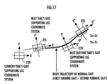
- FIG. 17 is a diagram illustrating a body trajectory of the normal gait and the supporting leg coordinate system
- FIG. 18 is a graph showing an example of a reference antiphase arm swing angle
- FIG. 19 is a graph showing a setting example of a desired floor reaction force vertical component trajectory in a normal gait
- FIG. 20 is a graph showing a setting example of a floor reaction force horizontal component permissible range in a normal gait
- FIG. 21 is a graph showing a setting example of a floor reaction force moment vertical component permissible range in the normal gait.
- FIG. 22 is a graph showing a setting example of the desired ZMP trajectory in the normal gait.
- FIG. 23 is a flowchart showing subroutine processing of S 024 in FIG. 13 .
- FIG. 24 is a flowchart showing subroutine processing of S 208 in FIG. 23 .
- FIG. 25 is a flowchart showing subroutine processing of S 306 in FIG. 24 .
- FIG. 26 is a flowchart showing subroutine processing of S 412 in FIG. 25 .
- FIG. 27 is a graph showing an example of a floor reaction force horizontal component in which a permissible range is not considered
- FIG. 28 is a graph showing an example of the floor reaction force horizontal component in which the permissible range is considered
- FIG. 29 is a graph showing an example of a body inclination angle acceleration
- FIG. 30 is a graph showing an example of a body inclination restoring moment ZMP-converted value for restoring a body inclination angle of the robot
- FIG. 31 is a graph showing an example of a body inclination angle acceleration in which the body inclination restoring moment ZMP-converted value is reflected
- FIG. 32 is a graph showing an example of a floor reaction force moment vertical component in which a permissible range is not considered
- FIG. 33 is a graph showing an example of a floor reaction force moment vertical component in which the permissible range is considered
- FIG. 34 is a graph showing an example of an antiphase arm swing moment
- FIG. 35 is a graph showing an antiphase arm swing angular acceleration corresponding to the antiphase arm swing moment shown in FIG. 34 ,
- FIG. 36 is a graph showing an example of an antiphase arm swing restoring angular acceleration for restoring an antiphase arm swing angle
- FIG. 37 is a graph showing an antiphase arm swing restoring moment corresponding to an antiphase arm swing restoring angular acceleration shown in FIG. 36 .
- FIG. 38 is a graph showing a floor reaction force moment vertical component formed by combining the floor reaction force moment vertical component shown in FIG. 33 and the antiphase arm swing restoring moment shown in FIG. 37 .
- FIG. 39 is a flowchart showing subroutine processing of S 026 in FIG. 13 .
- FIG. 40 is a graph showing a setting example of a floor reaction force horizontal component permissible range of a present gait
- FIG. 41 is a graph showing a setting example of a floor reaction force moment vertical component permissible range of the present gait
- FIG. 42 is a flowchart showing subroutine processing of S 028 in FIG. 13 .
- FIG. 43 is a flowchart showing subroutine processing of S 702 in FIG. 42 .
- FIG. 44 is a graph showing examples of a provisional desired ZMP of the present gait, a ZMP correction amount, and a desired ZMP after correction,
- FIG. 45 is a flowchart showing subroutine processing of S 030 in FIG. 13 .
- FIG. 46 is a flowchart showing subroutine processing of S 1412 in FIG. 45 .
- FIG. 47 is a graph showing a relationship between normal gaits and desired gaits relative to body position trajectories
- FIG. 48 is a diagram showing another example of a body inclination mode (body inclination about waist),
- FIG. 49 is a diagram for explaining another example of a dynamic model
- FIG. 50 is a diagram showing a setting example of a desired floor reaction force vertical component in a walking gait
- FIG. 51 is a diagram showing a relationship between the position in the body vertical direction and a floor reaction force vertical component in walking gaits of the robot.
- FIG. 52 is a diagram showing a relationship between the position in the body vertical direction and a floor reaction force vertical component in walking gaits of the robot.
- FIG. 53 is a block diagram showing a functional construction of a control unit in a first embodiment of the present invention.
- FIG. 54 is a block diagram showing the processing of a compensating total floor reaction force moment horizontal component distributor shown in FIG. 53 ,
- FIG. 55 is a block diagram showing the processing of a model manipulation floor reaction force moment vertical component determiner shown in FIG. 53 ,
- FIG. 56 is a flowchart showing main routine processing of a gait generator in the first embodiment
- FIG. 57 is a flowchart showing subroutine processing of S 3032 in FIG. 56 .
- FIG. 58 is a flowchart showing a subroutine processing of S 3414 in FIG. 57 .
- FIG. 59 is a block diagram showing a functional construction of a control unit in a second embodiment of the present invention.
- FIG. 60 is a flowchart showing main routine processing of a gait generator in the second embodiment
- FIG. 61 is a flowchart showing subroutine processing of S 2034 in FIG. 60 .
- FIG. 62 is a flowchart showing subroutine processing of S 2114 in FIG. 61 .
- FIG. 63 is a block diagram showing a functional construction of a gait generator in a third embodiment of the present invention.
- FIG. 64 is a diagram showing a setting example of a ZMP permissible range in the third embodiment
- FIG. 65 is a flowchart showing main routine processing of the gait generator in the third embodiment
- FIG. 66 is a block diagram showing processing of S 3536 in FIG. 65 .
- FIG. 67 is a diagram for explaining a horizontal body position perturbation model shown in FIG. 66 .
- FIG. 68 is a diagram for explaining a perturbation model for correcting body posture angle shown in FIG. 66 .
- FIG. 69 is a diagram for explaining a perturbation model for correcting antiphase arm swing angle shown in FIG. 66 .
- FIG. 70 is a block diagram showing processing of a moment determiner of the perturbation model for correcting the antiphase arm swing angle shown in FIG. 66 .
- FIG. 71 is a block diagram showing processing of S 3536 in FIG. 65 in a fourth embodiment of the present invention.
- FIG. 72 is a block diagram showing processing of the moment determiner of the perturbation model for correcting antiphase arm swing angle shown in FIG. 71 .
- FIG. 73 is a block diagram showing a functional construction of a gait generator in a fifth embodiment of the present invention.
- FIG. 74 is a block diagram showing processing of a pseudo order full model shown in FIG. 73 .
- FIG. 75 is a block diagram showing processing of S 3536 in FIG. 65 in a sixth embodiment of the present invention.
- FIG. 76 is a block diagram showing a functional construction of a control unit in a seventh embodiment of the present invention.
- FIG. 77 is a flowchart showing main routine processing of a gait generator in the seventh embodiment
- FIG. 78 is a flowchart showing processing of S 2334 in FIG. 77 .
- FIG. 79 is a flowchart showing the processing of a slippage determiner shown in FIG. 76 .
- FIG. 80 to FIG. 82 are flowcharts showing subroutine processing of S 5210 , S 5212 , and S 5214 , respectively, in FIG. 79 ,
- FIG. 83 is a graph showing examples of determination results of the slippage determiner, reducing rates of a permissible range, and floor reaction force permissible ranges,
- FIG. 84 is a block diagram showing modification examples related to the fourth to the sixth embodiments.
- FIG. 85 is a block diagram showing a modification example (an eighth embodiment) of the processing of the moment determiner of a perturbation model for correcting antiphase arm swing angle related to the third embodiment.
- FIG. 1 to FIG. 47 a reference example related to the control device of a legged mobile robot in accordance with the present invention will be explained.
- the embodiments of the present invention to be discussed hereinafter share the same mechanical constructions as that of the reference example, while they partly differ from the reference example in gait generation processing and control processing of a robot. For this reason, the explanation of the reference example will be frequently used in the explanation of the embodiments to be discussed hereinafter. Supplementally, the same matters that will be explained with reference to FIG. 1 and FIG. 2 , FIG. 3 and FIG. 5 to FIG. 12 to be discussed later will apply to the embodiments to be discussed later.
- FIG. 1 is a schematic diagram generally showing a bipedal mobile robot representing a legged mobile robot according to the present reference example.
- a bipedal mobile robot (hereinafter referred to as “the robot”) 1 is equipped with a pair of right and left legs (leg links) 2 , 2 provided such that they extend downward from a body (a base body of the robot 1 ) 3 .
- the two legs 2 , 2 share the same construction, each having six joints.
- the six joints of each leg are comprised of, in the following order from the body 3 side, joints 10 R, 10 L (symbols R and L meaning correspondence to the right leg and the left leg, respectively; the same will be applied hereinafter) for swinging (rotating) a hip (waist) (for rotating in a yaw direction relative to the body 3 ), joints 12 R, 12 L for rotating the hip (waist) in a roll direction (about an X axis), joints 14 R, 14 L for rotating the hip (waist) in a pitch direction (about a Y axis), joints 16 R, 16 L for rotating knees in the pitch direction, joints 18 R, 18 L for rotating ankles in the pitch direction, and joints 20 R, 20 L for rotating the ankles in the roll direction.
- a foot (foot portion) 22 R (L) constituting a distal portion of each leg 2 is attached to the bottoms of the two joints 18 R (L) and 20 R (L) of the ankle of each leg 2 .
- the body 3 is installed at the uppermost top of the two legs 2 , 2 through the intermediary of the three joints 10 R (L), 12 R (L) and 14 R (L) of the hip of each leg 2 .
- a control unit 60 or the like, which will be discussed in detail hereinafter, is housed inside the body 3 . For convenience of illustration, the control unit 60 is shown outside the body 3 in FIG. 1 .
- a hip joint (or a waist joint) is formed of the joints 10 R (L), 12 R (L) and 14 R (L), the knee joint is formed of the joint 16 R (L), and the ankle joint is formed of the joints 18 R (L) and 20 R (L).
- the hip joint and the knee joint are connected by a thigh link 24 R (L), and the knee joint and the ankle joint are connected by a crus link 26 R (L).
- a pair of right and left arms 5 , 5 is attached to both sides of an upper portion of the body 3 , and a head 4 is disposed at a top end of the body 3 .
- Each arm 5 is provided with a shoulder joint composed of three joints 30 R (L), 32 R (L), and 34 R (L) an elbow joint composed of a joint 36 R(L), a wrist joint composed of a joint 38 R (L), and a hand 40 R (L) connected to the wrist joint.
- the head 4 is not directly connected to a topic of the present invention, so that detailed explanation thereof will be omitted.
- the foot 22 R (L) of each leg 2 is given six degrees of freedom relative to the body 3 .
- This arrangement enables the robot 1 to arbitrarily move in a three-dimensional space.
- each arm 5 can perform a motion, such as arm swinging, by rotating its shoulder joint, the elbow joint, and the wrist joint.
- a publicly known six-axis force sensor 50 is provided between the ankle joints 18 R (L), 20 R (L) and the foot 22 R (L) of each leg 2 .
- the six-axis force sensor 50 detects primarily whether the foot 22 R (L) of each leg 2 is in contact with the ground, and a floor reaction force (landing load) acting on each leg 2 , and it outputs detection signals of three-direction components Fx, Fy, and Fz of a translational force of the floor reaction force and three-direction components Mx, My, and Mz of a moment to the control unit 60 .
- the body 3 is equipped with a posture sensor 54 for detecting an inclination angle of the body 3 relative to a Z-axis (vertical direction (gravitational direction)) and an angular velocity thereof, and a rotational angle (yaw angle) of the body 3 about the Z-axis and an angular velocity thereof, detection signals thereof being output from the posture sensor 54 to the control unit 60 .
- the posture sensor 54 is provided with a three-axis direction accelerometer and a three-axis direction gyro sensor. These detection signals of these sensors are used to detect posture angles (an inclination angle and a yaw angle) of the body 3 and an angular velocity thereof, and also used to estimate a self position/posture of the robot 1 .
- each joint of the robot 1 is provided with an electric motor 64 (refer to FIG. 3 ) for driving the joint, and an encoder (rotary encoder) 65 (refer to FIG. 3 ) for detecting a rotational amount of the electric motor 64 (a rotational angle of each joint). Detection signals of the encoder 65 are output from the encoder 65 to the control unit 60 .
- a joystick (operating device) 73 (refer to FIG. 3 ) is provided at an appropriate position of the robot 1 .
- the joystick 73 is constructed in such a manner that a request regarding a gait of the robot 1 , such as a request for turning the robot 1 that is moving straight, is input to the control unit 60 as necessary by operating the joystick 73 .
- FIG. 2 is a diagram schematically showing a basic construction of a distal portion (including each foot 22 R (L)) of each leg 2 in the present reference example.
- a spring mechanism 70 is installed between each foot 22 R (L) and the six-axis force sensor 50 , and a foot sole elastic member 71 made of rubber or the like is bonded to a foot sole (the bottom surface of each foot 22 R (L)).
- These spring mechanism 70 and the foot sole elastic member 71 constitute a compliance mechanism 72 .
- the spring mechanism 70 which will be discussed in detail later, is constructed of a square guide member (not shown), which is installed on the upper surface of the foot 22 R (L), and a piston-shaped member (not shown) installed adjacently to the ankle joint 18 R (L) (the ankle joint 20 R (L) being omitted in FIG. 2 ) and the six-axis force sensor 50 , and housed in the guide member through the intermediary of an elastic member (rubber or spring) so that it may be jogged.
- the foot 22 R (L) indicated by a solid line shown in FIG. 2 is in a state where it is subjected to no floor reaction force.
- the spring mechanism 70 and the foot sole elastic member 71 of the compliance mechanism 72 flex, causing the foot 22 R (L) to shift to the position/posture illustrated by a dashed line in the figure.
- the structure of the compliance mechanism 72 is important not only to ease a landing impact but also to enhance controllability, as explained in detail in, for example, Japanese Unexamined Patent Publication Application No. 5-305584 previously proposed by the present applicant.
- FIG. 3 is a block diagram showing a construction of the control unit 60 .
- the control unit 60 is comprised of a microcomputer, and includes a first calculator 90 and a second calculator 32 formed of CPUs, an A/D converter 80 , a counter 86 , a D/A converter 96 , a RAM 84 , a ROM 94 , and a bus line 82 for transferring data among them.
- output signals of the six-axis force sensor 50 , the posture sensor 54 (an accelerometer and a rate gyro sensor), the joystick 73 , etc. of each leg 2 are converted into digital values by the A/D converter 80 and sent to the RAM 84 via the bus line 82 .
- Outputs of the encoder 65 (rotary encoder) of each joint of the robot 1 are supplied to the RAM 84 via the counter 86 .
- the first calculator 90 generates desired gaits, calculates a joint angle displacement command (a displacement angle of each joint or a command value of a rotational angle of each electric motor 64 ), and sends the calculation result to the RAM 84 .
- the second calculator 92 reads an actual measurement value of a joint angle detected on the basis of the joint angle displacement command and an output signal of the encoder 65 from the RAM 84 to calculate a manipulated variable required for driving each joint, and outputs the calculated variable to the electric motor 64 for driving each joint through the intermediary of the D/A converter 96 and a servo amplifier 64 a.
- FIG. 4 is a block diagram showing the entire functional construction of a control unit of the legged mobile robot in accordance with the present reference example.
- a portion except for the “actual robot” in FIG. 4 is constituted by processing functions implemented by the control unit 60 (primarily the functions of the first calculator 90 and the second calculator 92 ).
- the symbols R and L will be omitted as long as it is not particularly necessary to discriminate right and left of the legs 2 and the arms 5 .
- the control unit 60 is equipped with a gait generator 100 for generating and outputting desired gaits of the robot 1 freely and in real time.
- the functions of the gait generator 100 constitute individual means of the present invention.
- a desired gait output by the gait generator 100 is constituted of a desired body position/posture trajectory (trajectory of a desired position and a desired posture of the body 3 ), a desired foot position/posture trajectory (trajectory of a desired position and a desired posture of each foot 22 ), a desired arm posture trajectory (trajectory of a desired posture of each arm 5 ), a desired total floor reaction force central point (desired ZMP) trajectory, and a desired total floor reaction force trajectory.
- a movable part relative to the body 3 is provided in addition to the legs 2 and the arms 5 , then a desired position/posture trajectory of the movable part is added to the desired gait.
- a posture of each part means a spatial orientation.
- a posture of a body is represented by an inclination angle of the body 3 in the roll direction (about the X-axis) relative to the Z-axis (vertical axis), an inclination angle of the body 3 in the pitch direction (about the Y-axis), and a rotational angle (yaw angle) of the body 3 in the yaw direction (about the Z-axis).
- a foot posture is represented by means of a spatial azimuth of two axes fixedly set on each foot 22 .
- a body posture may be referred to as a body posture angle.
- a posture relative to a vertical direction may be referred to as a body posture inclination or a body posture inclination angle.
- each foot reaction force floor reaction force comprised of a translational force and the moment
- a resultant force of the “each-foot floor reaction forces” of all (two) feet 22 R and 22 L of the robot 1 will be referred to as a “total floor reaction force”
- each-foot floor reaction forte will hardly be referred to, so that “floor reaction force” will be handled as having the same meaning as “total floor reaction force” unless otherwise specified.
- a desired floor reaction force is generally expressed by a point of action and a translational force and the moment acting on the point.
- the point of action may be set at any location, so that innumerable expressions are possible for the same desired floor reaction force. If, however, a desired floor reaction force is expressed using especially the aforesaid desired floor reaction force central point (a desired position of the floor reaction force central point) as the point of action, then the moment component of the desired floor reaction force will be zero except for a vertical component (the moment about the vertical axis (Z-axis)). In other words, the horizontal component of the moment of the desired floor reaction force about the desired floor reaction force central point (the moment about the horizontal axis (the X-axis and the Y-axis)) will be zero.
- a ZMP calculated from a desired motion trajectory of the robot 1 (a point at which the moment of a resultant force of an inertial force and gravity calculated from the desired motion trajectory acts about the point becomes zero except for a vertical component) agrees with a desired floor reaction force central point. Therefore, providing a desired ZMP trajectory may be regarded as equivalent to providing a desired floor reaction force central point trajectory (refer to, for example, PCT Kokai publication WO/02/40224 by the present applicant for more details).
- a desired gait is a combination of a desired motion trajectory and a desired floor reaction force trajectory thereof in a period of one step or a plurality of steps.
- a desired gait is a combination of a desired motion trajectory and a ZMP trajectory thereof in a period of one step.
- a series of gaits is formed of several gaits that are connected.
- a vertical position of the body 3 of the robot 1 (a height of the body) is determined by a body height determining technique proposed previously in Japanese Unexamined Patent Application Publication No. 10-86080 by the present applicant. This subordinately determines a translational floor reaction force vertical component. Furthermore, a translational floor reaction force horizontal component is also determined by determining the horizontal body position trajectory of the robot 1 such that the horizontal component of the moment produced about a desired ZMP by a resultant force of the inertial force and the gravity generated by the motion of a desired gait becomes zero. For this reason, a desired ZMP alone has been adequate as a physical amount to be explicitly set for the floor reaction force of a desired gait in the description of PCT Kokai publication WO/02/40224.
- a floor reaction force vertical component (a translational floor reaction force vertical component) is also important for control.
- a desired trajectory of the floor reaction force vertical component is explicitly set, and then a trajectory of a desired vertical body position or the like of the robot 1 is determined.
- the following b′) will be adopted as the definition of a desired gait in a narrow sense.
- a desired gait in a narrow sense is a combination of a desired motion trajectory and a desired floor reaction force trajectory including at least a ZMP trajectory of the desired motion trajectory and a desired translational floor reaction force vertical component trajectory in a period of one step.
- a desired gait used hereinafter will mean the desired gaits in the narrow sense of the above b′) unless otherwise specified for the purpose of easy understand.
- “one step” of a desired gait will mean a period from the moment one leg 2 of the robot 1 touches the ground to the moment the other leg 2 touches the ground.
- a desired gait is used to mean a gait for one-step period. This, however, does not have to be necessarily the one-step period; it may alternatively be a period for a plurality of steps or a period that is shorter than one step (e.g., a half step).
- floor reaction force vertical component will mean “translational floor reaction force vertical component,” and the term “moment” will be used for the vertical component (the component about the vertical axis) of a moment of a floor reaction force so as to distinguish it from the “floor reaction force vertical component.”
- floor reaction force horizontal component will mean “translational floor reaction force horizontal component.”
- a double stance period in a gait will refer to a period during which the robot 1 supports its own weight by the two legs 2 , 2 .
- a single stance period will refer to a period during which the robot 1 supports its own weight only by one leg 2
- a floating period will refer to a period during which both legs 2 , 2 are apart from a floor (floating in the air).
- the leg 2 not supporting the self-weight of the robot 1 will be referred to as a “free leg.”
- the running gait explained in the present reference example does not have the double stance period, but alternately repeats the single stance period (landing period) and the floating period.
- both legs 2 , 2 do not support the self-weight of the robot 1 ; however, the leg 2 that was a free leg and the leg 2 that was a supporting leg during a single stance period immediately before the floating period will be referred to as a “free leg” and a “supporting leg,” respectively, even in the floating period.
- This running gait is a gait similar to a typical human running gait.
- this running gait the single stance period in which the foot 22 of only either the right or left leg 2 (supporting leg) of the robot 1 lands (contacts the ground) and a floating period in which both the legs 2 , 2 float in the air are alternately repeated.
- the first state illustrates a state wherein a single stance period has begun (initial stage)
- the second state illustrates a state of a midpoint of the single stance period
- the third state illustrates a state wherein a floating period following the single stance period has begun (an end of the single stance period)
- the fourth state illustrates a state of a midpoint of the floating period
- the fifth state illustrates an end of the floating period (a start of the next single stance period).
- the robot 1 lands at the heel of the foot 22 of the supporting leg (the leg 2 on the front side in the advancing direction of the robot 1 ) at the beginning of the single stance period, as shown in the first state of FIG. 5 . Subsequently, the robot 1 brings substantially the entire surface of the sole of the landed foot 22 (the foot 22 of the supporting leg) into contact with the ground as shown in the second state of FIG. 5 , and then kicks the floor with the tiptoe of the foot 22 (the foot 22 of the leg 2 on the rear side with respect to the advancing direction of the robot 1 in the third state of FIG. 5 ) of the supporting leg to jump into the air as shown in the third state of FIG. 5 .
- the free leg in the single stance period exists behind the supporting leg at the beginning of the single stance period as shown in the first state of FIG. 5 , but swung out to the front of the supporting leg toward the next predetermined landing position, as shown in the second and the third states of FIG. 5 .
- the robot 1 lands at the heel of the foot 22 of the free leg (the leg 2 that was the free leg in the single stance period immediately before the floating period started), and the next single stance period is begun.
- a basic outline of a desired gait generated by the gait generator 100 will be explained. Although more details will be discussed later, when the gait generator 100 generates a desired gait, basic required values (required parameters) for generating the desired gait, such as a landing position/posture (expected landing position/posture) of the foot 22 of a free leg and a landing time (expected landing time), are supplied to the gait generator 100 according to a required operation or the like of the joystick 73 . The gait generator 100 then generates the desired gait using the required parameters.
- basic required values for generating the desired gait, such as a landing position/posture (expected landing position/posture) of the foot 22 of a free leg and a landing time (expected landing time)
- the gait generator 100 then generates the desired gait using the required parameters.
- the gait generator 100 determines parameters (referred to as gait parameters) that specify some constituent elements of the desired gait, such as a desired foot position/posture trajectory and a desired floor reaction force vertical component trajectory, on the basis of the above required parameters, and then sequentially determines instantaneous values of the desired gait by using the gait parameters so as to generate a time series pattern of the desired gait.
- gait parameters parameters that specify some constituent elements of the desired gait, such as a desired foot position/posture trajectory and a desired floor reaction force vertical component trajectory
- a desired foot position/posture trajectory (to be more specific, a desired trajectory of each spatial component (X-axis component or the like) of the position and the posture of a foot) is generated for each foot 22 by using a finite-duration setting filter proposed in U.S. Pat. No. 3,233,450 by the present applicant.
- This finite-duration setting filter includes a plurality of stages ( 3 states or more in the present reference example) of first-order lag filters of variable time constants, that is, filters represented in terms of a transfer function of 1/(1+ ⁇ s) ( ⁇ is a variable time constant.
- the filter will be referred to as a unit filter), the plurality of stages of the filters being connected in series.
- Every time constant ⁇ of the unit filter of each stage is variably set in sequence according to remaining time until the above specified time after starting the generation of an output of the finite-duration setting filter. More specifically, the setting is made such that, the value of ⁇ is decreased from a predetermined initial value (>0) as the remaining time reduces, and the value of ⁇ finally reaches zero at the specified time at which the remaining time reaches zero.
- a step input of a height based on the specified value (more specifically, a change amount from an initial value to the specified value of an output of the finite-duration setting filter) is supplied to the finite-duration seating filter.
- the finite-duration setting filter not only generates an output that reaches a specified value at specified time but also makes it possible to set a changing rate of an output of the finite-duration setting filter at specified time to zero or substantially zero. Especially when three stages or more (three stages will do) of the unit filters are connected, the changing acceleration (a differential value of a changing rate) of an output of the finite-duration setting filter can be reduced to zero or substantially zero.
- the desired foot position/posture trajectory generated by the finite-duration setting filter as described above is the desired position/posture trajectory of each foot 22 on a supporting leg coordinate system, which is fixed on a floor surface and which is to be discussed later.
- the desired foot position/posture trajectory generated as described above is generated such that the position of each foot 22 begins moving, while gradually accelerating from the initial in-contact-with-the-ground state (the state at the initial time of a desired gait) toward an expected landing position.
- the desired foot position/posture trajectory is generated such that the changing rate of the position is gradually decelerated to zero or substantially zero until the expected landing time is finally reached, and the expected landing position is reached at the expected landing time, stopping the movement.
- the ground speed at the moment each foot 22 lands becomes zero or substantially zero (the changing rate of the position of each foot 22 on the supporting leg coordinate system secured to a floor). Accordingly, a landing impact will be low even when the robot 1 lands from the state wherein all legs 2 , 2 are simultaneously present in the air (the state in the floating period) in a running gait.
- the vertical velocity of the body 3 switches downward from the latter half of the floating period due to the gravity acting on the robot 1 , and remains downward at the time of landing. Therefore, the relative velocity of the foot 22 of a free leg with respect to the body 3 switches upward immediately before landing if the desired foot position/posture trajectory is generated such that the ground speed at the moment each foot 22 lands reaches zero or substantially zero, as described above, and if the desired position/posture trajectory of the body 3 is generated to satisfy a dynamic balance condition, as will be discussed later.
- the desired gait of the robot 1 is such that the robot 1 lands, withdrawing the leg 22 that is a free leg toward the body 3 .
- the robot 1 lands while pulling the foot 22 up, as observed from the body 3 , so that the ground speed of the foot 22 of the free leg reaches zero or substantially zero. This restrains a landing impact to prevent the landing impact from becoming excessive.
- the finite-duration setting filter is composed of three stages of more (e.g., three stages) of the unit filters connected in series, so that the velocity of each foot 22 (the changing rate of a foot position) reaches zero or substantially zero by expected landing time and the acceleration of each foot 22 also reaches zero or substantially zero at the expected landing time when the movement stops.
- the ground acceleration also becomes zero or substantially zero at the landing instant.
- the landing impact will be further restrained. Especially, even if actual landing time of the robot 1 deviates from desired landing time, the impact no longer increases much.
- the number of stages of the unit filters of the finite-duration setting filter may be two to make setting so that the ground speed of each foot 22 reaches zero or substantially zero at expected landing time. In this case, however, the acceleration of each foot 22 at expected landing time does not usually become zero.
- the foot position trajectory has been generated using the finite-duration setting filter.
- a desired foot position trajectory may be generated using a function, such as a polynomial, that is set such that the changing rate of a foot position at the expected landing time (a time differential value of a foot position) reaches zero or substantially zero and further the changing acceleration of the foot position at the expected landing time (a time differential value of the changing rate) reaches zero or substantially zero. This applies also to the generation of a desired foot posture trajectory.
- a function such as a polynomial, is set such that the changing rate of the posture of each foot 22 and the changing acceleration thereof reaches zero or substantially zero at the time when substantially the entire sole of each foot 22 comes in contact with a floor, as described above.
- a desired floor reaction force vertical component trajectory is set as shown in, for example, FIG. 6 .
- the shape of a desired floor reaction force vertical component trajectory in a running gait is (specified to be trapezoidal (a shape projecting to an increasing side of a floor reaction force vertical component).
- the height of the trapezoid and the time of a bending point are regarded as gait parameters defining a desired floor reaction force vertical component trajectory, and the gait parameters (floor reaction force vertical component trajectory parameters) are determined.
- the desired floor reaction force vertical component is steadily set to zero.
- a desired floor reaction force vertical component trajectory is desirably set so that it is virtually continuous (so that values are not discontinuous), as in the case of the present example. This is for ensuring smooth operations of joints of the robot 1 when controlling a floor reaction force.
- virtual continuous means that a skipped value that inevitably takes place when a trajectory that is continuous in an analog fashion (a continuous trajectory in a true meaning) is digitally expressed by a discrete-time system does not cause the continuity of the trajectory to be lost.
- a desired ZMP trajectory is set as follows. In the running gait shown in FIG. 5 , the robot 1 lands at the heel of the foot 22 of a supporting leg, and then kicks at the tiptoe of the foot 22 of the supporting leg to jump into the air. Lastly, the robot 1 lands at the heel of the foot 22 of a free leg, as described above. Therefore, as shown in the upper diagram of FIG.
- the desired ZMP trajectory in the single stance period is set such that it takes the heel of the foot 22 of the supporting leg as its initial position, and then extends to the center in the longitudinal direction of the foot 22 in the period in which substantially the entire sole of the foot 22 of the supporting leg comes on contact with the ground, and thereafter, reaches the tiptoe of the foot 22 of the supporting leg by floor leaving time.
- the upper diagram of FIG. 7 shows a desired ZMP trajectory in an X-axis direction (longitudinal direction), while a lower diagram of FIG. 7 shows a desired ZMP trajectory in a Y-axis direction (lateral direction).
- the desired ZMP trajectory in the Y-axis direction in a single stance period is set at the same position as the central position of an ankle joint of a supporting leg 2 in the Y-axis direction, as shown in the lower diagram of FIG. 7 .
- both legs 2 , 2 leave a floor, and the floor reaction force vertical component becomes zero.
- the floor reaction force vertical component is zero, that is, during a floating period, the total center of gravity of the robot 1 is subject to free fall motion, and an angular momentum change about the total center of gravity is zero.
- the moment of a resultant force of gravity and an inertial force that acts on the robot 1 is zero at an arbitrary point of a floor, so that a desired ZMP is indefinite.
- the desired ZMP may be set discontinuously.
- the desired ZMP may be set so that it does not move from a desired ZMP position when leaving a floor (when a single stance period ends) in a floating period, and it moves discontinuously (in steps) to a desired ZMP position for landing at the end of the floating period.
- the position of the desired ZMP trajectory in the X-axis direction in a floating period has been set so as to continuously move to the landing position of the heel of the foot 22 of a free leg from the tiptoe of the foot 22 of a supporting leg by the time the next free leg 2 lands, as shown in the upper diagram of FIG. 7 .
- the position of the desired ZMP trajectory in the Y-axis direction in a floating period has been set so as to continuously move to the Y-axis directional position of the center of the ankle joint of a free leg from the Y-axis directional position of the center of the ankle joint of a supporting leg 2 by the time the next free leg 2 lands.
- the desired ZMP trajectory has been set so that it is continuous (virtually continuous) in all periods of a gait.
- a desired gait has been generated so that a moment of the resultant force of gravity and an inertial force (excluding a vertical component) about the desired ZMP becomes zero (to be more specific, a desired body position/posture trajectory has been adjusted).
- the desired ZMP trajectory is desirably set to be continuous (virtually continuous) also in a floating period in order to ensure a smooth generated gait.
- a dynamic model which is used in the present reference example and which will be discussed later, makes it possible to uniquely generate a desired gait that sets the horizontal component of a moment about a desired ZMP at a certain value (the value is zero in the present reference example, whereas it is not necessarily zero in embodiments, which will be described hereinafter) independently of the position of a desired ZMP. Therefore, the desired ZMP does not have to be always continuous.
- the positions and time of the bending points of the desired ZMP trajectory as shown in FIG. 7 are set as ZMP trajectory parameters (parameters defining the desired ZMP trajectory).
- the meaning of “virtually continuous” of the aforementioned ZMP trajectory is the same as that in the case of the above floor reaction force vertical component trajectory.
- the ZMP trajectory parameters are determined such that a high stability margin is secured and no sudden change Lakes place.
- a state in which a desired ZMP exists near the center of a least convex polygon (so-called supporting polygon) that includes a ground contact surface of the robot 1 indicates a high safety margin (refer to Japanese Unexamined Patent Application Publication No. 10-86081 for more detail).
- the desired ZMP trajectory shown in FIG. 7 has been set to meet such a condition.
- a desired body position/posture, a desired foot position/posture, and a reference body posture which will be discussed hereinafter, are described in terms of a global coordinate system.
- the global coordinate system is a coordinate system fixed to a floor. More specifically, a supporting leg coordinate system to be discussed hereinafter is used as the global coordinate system.
- the gait generator 100 generates a reference body posture in addition to a desired body posture.
- the reference body posture is a body posture generated directly on the basis of requests regarding a gait (requests from a unit, such as an action scheduler, or from an external source (the joystick 73 or the like) sent to the gait generator 100 ).
- a desired body posture (representing hereinafter a desired body posture unless “reference” is added) is generated such that it follows or agrees with a reference body posture in a long term.
- a desired body posture may be always set to agree with a reference body posture as in the case of an embodiment disclosed in the description of PCT Kokai publication WO/02/40224.
- PCT Kokai publication WO/02/40224 does not refer to the concept of the reference body posture, it explicitly and preferentially gives desired body posture patterns, which is equivalent to steady agreement of desired body postures with a reference body posture.
- a desired body posture is deliberately deviated from a reference body posture, as necessary.
- motion modes explained below are generated in a combined manner so as to satisfy the dynamic balance condition while having a floor reaction force horizontal component and a floor reaction force moment vertical component of a desired gait falling within a permissible range (or within a friction limit).
- a total center-of-gravity horizontal acceleration and an angular momentum about the total center-of-gravity of the robot 1 are perturbated. More specifically, perturbating the body horizontal acceleration perturbates the floor reaction force moment horizontal component about a desired ZMP (a component about the horizontal axis) and the floor reaction force horizontal component without perturbating the floor reaction force vertical component that dynamically balances with a resultant force of an inertial force and gravity of the robot 1 produced by the perturbation of the body horizontal acceleration (without perturbating a total center-of-gravity vertical acceleration of the robot 1 ).
- the motion mode that perturbs the body horizontal acceleration of the robot 1 as described above is referred to as a body translational mode.
- a motion in which the floor reaction force moment horizontal component about the desired ZMP and the floor reaction force horizontal component are changed without changing the floor reaction force vertical component is referred to as the body translational mode.
- the floor reaction force moment vertical component the component about the vertical axis
- the floor reaction force moment vertical component is also perturbated; however, no attention will be paid to this aspect in this case.
- a change in the floor reaction force moment horizontal component per unit acceleration at this time is denoted by ⁇ Mp and a change in the floor reaction force horizontal component per unit acceleration is denoted by ⁇ Fp. If the body 3 is horizontally accelerated forward in the situation illustrated in FIG. 8 , then ⁇ Mp and ⁇ Fp act in the directions of the arrows shown in FIG. 8 .
- the floor reaction force that balances with the resultant force of an inertial force and gravity generated by a motion has been used for expression.
- it is theoretically more accurate to express using the resultant force of an inertial force and gravity.
- the above resultant force and the floor reaction force have the same magnitude but opposite directions.
- the body inclination angular acceleration (the angular acceleration of the inclination angle of the body 3 ) is perturbated about a certain point Pr from a certain motion state of the robot 1 , as shown in FIG. 9 , then the angular momentum (excluding the component about the vertical axis) about the total center-of-gravity is perturbated, while the total center-of-gravity of the robot 1 is not perturbated.
- perturbating the body inclination angle acceleration about the point Pr perturbates the floor reaction force moment horizontal component about a desired ZMP without perturbating the floor reaction force vertical component and the floor reaction force horizontal component.
- the motion mode in which the body inclination angle acceleration of the robot 1 is perturbated as described above is referred to as the body inclination mode.
- the motion in which the floor reaction force moment horizontal component about a desired ZMP is changed without changing a floor reaction force vertical component and a floor reaction force horizontal component is called the body inclination mode.
- a change in the floor reaction force moment horizontal component per unit angular acceleration at this time is denoted by ⁇ Mr and a change in the floor reaction force horizontal component per unit angular acceleration is denoted by ⁇ Fr.
- ⁇ Fr is zero. If an angular acceleration of a body inclination angle is generated to cause the body 3 to lean forward in the situation shown in FIG. 9 , then ⁇ Mr acts in the direction of the arrow shown in FIG. 9 .
- a body yaw angle acceleration (the rotational angular acceleration about the vertical axis of the body 3 ) is perturbated about a certain point Pq from a certain motion state of the robot 1 , as shown in FIG. 10 , then the angular momentum vertical component about the total center-of-gravity is perturbated, while the total center-of-gravity of the robot 1 is not perturbated.
- the perturbation of the angular momentum vertical component does not depend on a point of action.
- perturbating the body yaw angular acceleration about the point Pq perturbates the floor reaction force moment vertical component about a desired ZMP without perturbating the floor reaction force vertical component, the floor reaction force horizontal component, and the floor reaction force moment horizontal component.
- the motion mode in which the body yaw angular acceleration of the robot 1 is perturbated as described above is referred to as the body yaw rotation mode.
- the body motion in which the floor reaction force moment vertical component about a desired ZMP is changed without changing a floor reaction force vertical component, a floor reaction force horizontal component, and a floor reaction force moment horizontal component is called the body yaw rotation mode.
- a change in the floor reaction force moment vertical component per unit angular acceleration at this time is denoted by ⁇ Mbz
- a change in the floor reaction force horizontal component per unit angular acceleration is denoted by ⁇ Fb.
- the body 3 has been rotated so that the positions of the distal ends of both arms 5 , 5 remain unchanged as observed from the supporting leg coordinate system (the coordinate system fixed to a floor).
- a motion in which an arm 5 is rotated together with the body 3 without changing the relative position/posture of the arm 5 in relation to the body 3 may be defined as the body yaw rotation mode. In this case, however, a motion equation to be discussed hereinafter has to be slightly changed.
- this motion mode will be referred to as an antiphase arm swing mode.
- the arm swing motion mode in which the floor reaction force moment vertical component about a desired ZMP is perturbated without perturbating a floor reaction force vertical component, a floor reaction force horizontal component, and a floor reaction force moment horizontal component is referred to as the antiphase arm swing mode.
- FIGS. 11 ( a ) and ( b ) illustrate a state wherein an antiphase arm swing angle is ⁇ az.
- a change in the floor reaction force moment vertical component per unit angular acceleration in the antiphase arm swing mode is denoted by ⁇ Maz
- a change in the floor reaction force horizontal component per unit angular acceleration is denoted by ⁇ Fa.
- ⁇ Fa is zero.
- a floor reaction force moment vertical component Maz acts in the direction of the arrow (a positive direction of the vertical axis) shown in FIG. 11 ( a ).
- a dynamic model of the robot 1 used in the present reference example a simplified (approximated) dynamic model shown below is used.
- a kinematics model a model representing the structures and dimensions of joints and links, i.e., a model representing a relationship between joint displacements and the positions/postures of links
- FIG. 12 shows a dynamic model of the robot 1 used in the present reference example.
- the dynamic model is a model composed of a total of three mass points, namely, two mass points 2 m , 2 m corresponding to the legs 2 of the robot 1 and a mass point 3 m corresponding to the body 3 , and four flywheels FHx, FHy, FHbz, and FHaz having inertias but no mass.
- the flywheels FHx, FHy, FHbz, and FHaz can be rotated about an X-axis (longitudinal axis), a Y-axis (lateral axis), a Z-axis (vertical axis), and a Z-axis (vertical axis), respectively.
- This dynamic model is decoupled, that is, the dynamic model is constructed such that the dynamics (the dynamics of the mass points 2 m , 2 m ) of the legs 2 , 2 , the dynamics of the body 3 (the dynamics of the mass point 3 m and the flywheels FHx, FHy and FHbz), and the dynamics of the arms 5 , 5 (the dynamics of the flywheel FHaz) do not interfere with each other, and the dynamics of the entire robot 1 is represented by their linear connection.
- a relationship between a motion of the body 3 and a floor reaction force is separated into a relationship between a translational motion of the body 3 (body translation mode) and a floor reaction force, a relationship between an inclination motion of the body 3 (body inclination mode) and a floor reaction force, a relationship between a yaw rotational motion of the body 3 (body yaw rotation mode) and a floor reaction force, and a relationship between an antiphase arm swing motion of both arms 5 , 5 (antiphase arm swing mode) and a floor reaction force.
- a floor reaction force generated by a horizontal motion of the body mass point 3 m corresponds to a floor reaction force generated by a horizontal translational motion of the body 3 (body translation mode)
- a floor reaction force generated by a rotational motion of the flywheels FHx and FHy corresponds to a floor reaction force generated by a rotational motion of an inclination angle of the body 3 (body inclination mode).
- the rotational motion of the flywheel FHx corresponds to the rotational motion of an inclination angle of the body 3 in the roll direction (about the X-axis)
- the rotational motion of the flywheel FHy corresponds to the rotational motion of an inclination angle of the body 3 in the pitch direction (about the y-axis).
- a floor reaction force generated by the rotational motion of the flywheel FHbz corresponds to a floor reaction force generated by a yaw rotational motion of the body 3 (the body yaw rotation mode).
- a floor reaction force generated by the rotational motion of the flywheel FHaz corresponds to a floor reaction force generated by an antiphase arm swing motion (the antiphase arm swing mode).
- the mass of the arms of the robot 1 is assumed to be included in the body 3 , and the body mass point 3 m has a mass that includes the mass of the arms 5 , 5 .
- Each of the mass points 2 m , 2 m and 3 m corresponds to a representative point of a part with which it is associated or a point uniquely decided geometrically from the position/posture of the part.
- the position of the mass point 2 m of a supporting leg 2 is defined as the point above the aforesaid representative point of the sole of the foot 22 of the leg 2 by a predetermined distance.
- Body mass point X position (The body mass point position is the position offset by a predetermined distance in the longitudinal direction of the body from the aforesaid point Pr. The offset is determined such that the gravitational center position of an exact model and the gravitational center position of the present dynamic model agree with each other as much as possible in an upright stance or the like.
- Yb Body mass point Y position
- XGtotal Overall gravitational center horizontal
- X position YGtotal: Overall gravitational center horizontal
- ⁇ bx Body inclination angle about X-axis relative to vertical direction
- ⁇ by Body inclination angle about Y-axis relative to vertical direction
- ⁇ bz Body yaw rotational angle
- ⁇ az Antiphase arm swing angle
- J Body inertial moment (Equivalent inertial moment in the body inclination mode.
- this is an inertial moment of FHx and FHy. Usually, it does not agree with the inertial moment of the body 3 part of the actual robot 1 .
- Jbz Body inertial moment about a vertical axis (Equivalent inertial moment in the body yaw rotation mode. Usually, this does not agree with the inertial moment of the body 3 part of the actual robot 1 .
- Jaz Arm swing inertial moment about a vertical axis (Equivalent inertial moment in antiphase arm swing to cancel a spin.
- Fx Floor reaction force X component (More specifically, a longitudinal (X-axis) component of a translational floor reaction force)
- Fy Floor reaction force Y component (More specifically, a lateral (Y-axis) component of a translational floor reaction force)
- Fz Floor reaction force vertical component (More specifically, a vertical (Z-axis) component of a translational floor reaction force.
- Mx X component of a floor reaction force moment about a desired ZMP (More specifically, a component about a longitudinal axis (X-axis) of a floor reaction force moment)
- My Y component of a floor reaction force moment about a desired ZMP (More specifically, a component about a lateral axis (Y-axis) of a floor reaction force moment)
- Mz Z component of a floor reaction force moment about a desired ZMP (More specifically, a component about a vertical axis (Z-axis) of a floor reaction force moment)
- An X position and a Y position of each of the mass points 2 m and 3 m mean a position in the longitudinal direction (X-axis direction) and a position in the lateral direction (Y-axis direction), respectively.
- a positional relationship between a position of the mass point 2 m of each leg 2 and a position of the foot 22 of the leg 2 is determined in advance, so that one of the positions is decided, then the other position is uniquely decided.
- a positional relationship between the body mass point 3 m and the position of the body 3 is determined in advance on the basis of a posture angle of the body 3 (hereinafter, regarding the body, a posture angle will mean an inclination angle and a yaw angle), and if a position and a posture angle of one of them are determined, then a position of the other is uniquely determined.
- dX/dt denotes first order differentiation of X
- d2X/dt2 denotes second order differentiation. Therefore, if the variable X denotes displacement, then dX/dt means velocity and d2X/dt2 means acceleration.
- g denotes a gravity acceleration constant. Here, g takes a positive value.
- Equation 01 A notional equation of the above dynamic model (an equation expressing a dynamic balance condition) is represented by equation 01, equation 02 ⁇ , equation 02y, equation 03x, equation 03y, and equation 03z.
- Fz mb* ( g+d 2 Zb/dt 2)+ msup* ( g+d 2 Zsup/dt 2)+ mswg* ( g+d 2 Zswg/dt 2) Equation 01
- Fx mb*d 2 Xb/dt 2 +msup*d 2 Xsup/dt 2 +mswg*d 2 Xswg/dt 2 Equation 02x
- Fy mb*d 2 Yb/dt 2 +msup*d 2 Ysup/dt 2 +mswg*d 2 Yswg/dt 2 Equation 02y
- Mx mb* ( Yb ⁇ Yzmp )*( g+d 2 Zbidt 2) ⁇ mb* ( Zb ⁇ Z
- the change ⁇ Fp of a floor reaction force horizontal component per unit acceleration in the direction of each horizontal axis (X-axis, Y-axis) in the body translation mode corresponds to the mass of the body mass point 3 m of the dynamic model.
- the change ⁇ Mp of a floor reaction force moment horizontal component per unit acceleration in the direction of each horizontal axis (X-axis, Y-axis) in the body translation mode is obtained by multiplying a body mass point mass of the dynamic model by a height (vertical position) of the body mass point 3 m from a desired ZMP.
- the relationship between the positions of the body mass point 3 m and the desired ZMP and the motion of the body mass point 3 m corresponds to the behavior of an inverted pendulum obtained when the body mass point 3 m is associated with an inverted pendulum mass point and when the desired ZMP is associated with an inverted pendulum supporting point.
- ⁇ Mp in the Y-axis direction is obtained by reversing the sign of the right side of equation 07.
- the change ⁇ Mr of a floor reaction force moment horizontal component per unit acceleration in the direction of each horizontal axis (X-axis, Y-axis) in the body inclination mode corresponds to the inertial moments of horizontal axis flywheels (FHx and FHy).
- the change ⁇ Mbz of a floor reaction force moment component per unit acceleration in the body yaw rotation mode corresponds to the inertial moment of a flywheel FHbz corresponding to body yaw rotation.
- the change ⁇ Maz of a floor reaction force moment component per unit angular acceleration of an antiphase arm swing corresponds to the inertial moment of a flywheel FHaz corresponding to an arm swing.
- the gait generator 100 in the present reference example generates a desired gait for one step in order, the desired gait (the desired gait in the narrow sense described above) for one step from the moment one leg 2 of the robot 1 lands to the moment the other leg 2 lands.
- the desired gait the desired gait in the narrow sense described above
- a desired gait that is being newly generated will be referred to as a “current time gait,” the next desired gait will be referred to as a “next gait,” and a desired gait after next will be referred to as a “next but one time gait.” Furthermore, a desired gait generated one step before the “current time gait” will be referred to as a “last time's gait.”
- the gait generator 100 When the gait generator 100 newly generates a current time gait, expected positions/postures of landing of the foot 2 ; of a free leg and required values (requests) of expected landing time for the next two steps of the robot 1 are input as required parameters to the gait generator 100 (or the gait generator 100 reads the required parameters from a memory). Then, the gait generator 100 uses these required parameters to generate a desired body position/posture trajectory, a desired foot position/posture trajectory, a desired ZMP trajectory, a desired floor reaction force vertical component trajectory, a desired arm posture trajectory, etc. At this time, some of the gait parameters specifying these trajectories are corrected, as necessary, to secure continuity of walking.
- FIG. 13 is a flowchart (structured flowchart) illustrating a main routine of the gait generation processing carried out by the gait generator 100 .
- S 010 various initializing operations, including initialization of time t to zero, are performed in S 010 .
- This processing is implemented primarily when starting up the gait generator 100 .
- the processing proceeds to S 014 via S 012 and waits for a timer interrupt for each control cycle (the calculation processing cycle of the flowchart shown in FIG. 13 ).
- the control cycle is denoted by ⁇ t.
- the processing proceeds to S 016 and determines whether a shift in a gait is taking place. If a shift in the gait is taking place, then the processing proceeds to S 018 , or if a shift in a gait is not taking place, then it proceeds to S 030 .
- the shift in a gait means a timing at which the generation of the last time's gait has been completed and the generation of the current time gait is about to start. For instance, a control cycle following the control cycle in which the generation of a last time's gait has been completed refers to the shift in a gait.
- time t is initialized to zero.
- the gait generator 100 then proceeds to S 020 and reads a next time's gait supporting leg coordinate system, a next but one time's gait supporting leg coordinate system, a current time gait cycle, and a next time gait cycle.
- These supporting leg coordinate systems and the gait cycles are determined by the above required parameters. More specifically, in the present reference example, the required parameters supplied to the gait generator 100 from the joystick 73 or the like include required values of expected landing positions/postures (foot positions/postures in a state wherein the foot 22 has been rotated without slippage such that its sole is substantially in full contact with a floor surface after landing) and expected landing time of the foot 22 of a free leg for up to two steps ahead.
- the required value for the first step and the required value for the second step are supplied to the gait generator 100 as the values associated with a current time gait and a next gait, respectively, before the generation of the current time gait is begun (the shift in a gait in S 016 mentioned above). These required values can be changed in the middle of generating the current time gait.
- the next time's gait supporting leg coordinate system is determined on the basis of the required value of the expected landing position/posture of the free leg foot 22 of the first step (the free leg foot 22 in the current time gait) in the above required parameters.
- the required value for an expected landing position/posture of the free leg foot 22 ( 22 L in the figure) related to the current time gait specifies a position/posture obtained by moving by xnext and ynext in the X-axis direction (in the longitudinal direction of a supporting leg foot 22 R of the current time gait) and in the Y-axis direction (in the lateral direction of the supporting leg foot 22 R of the current time gait), respectively, of a current time's gait supporting leg coordinate system, and by rotating about the Z-axis (about the vertical axis) by ⁇ znext with respect to a landing position/posture of the supporting leg foot 22 ( 22 R in the figure) of the current time gait.
- the supporting leg coordinate system is a global coordinate system (a coordinate system fixed to a floor) in which a point, at which a perpendicular line extended onto a floor surface from the center of the ankle of a supporting leg foot 2 intersects with the floor surface (this point agreeing with a representative point of the foot 22 in a state, wherein substantially the entire surface of the sole of the supporting leg foot 22 is in contact with the floor surface in the present reference example), in a state wherein the supporting leg foot 22 is set in a horizontal posture (more generally, a posture parallel to the floor surface) and substantially the entire surface of the sole of the supporting leg foot 22 is in contact (in close contact) with the floor surface, is defined as an origin thereof, and a horizontal plane passing the origin is defined as an XY plane.
- the X-axis direction and the Y-axis direction correspond to the longitudinal direction and the lateral direction, respectively, of the supporting leg foot 22 .
- the origin of the supporting leg coordinate system does not have to agree with the representative point of the foot 22 (a point representing the position of the foot 22 ) in the state wherein substantially the entire surface of the sole of the supporting leg foot 22 is in contact with the floor surface.
- the origin may be set at a point on the floor surface that is different from the representative point.
- the next time's gait supporting leg coordinate system is a coordinate system that takes, as its origin, the representative point (more specifically, a point on a floor that agrees with the representative point) of the foot 22 L in a case where the foot 22 is landed according to a required value of the expected landing position/posture of the free leg foot 22 L of the current time gait as illustrated (in a case where the representative point of the foot 22 is made to agree with the required value of an expected landing position and the posture (orientation) of the foot 22 is made to agree with the required value of an expected landing posture), the longitudinal direction and the lateral direction of the foot 22 L in the horizontal plane passing the origin corresponding to an X′-axis direction and Y′-axis direction, respectively.
- a next but one time's gait supporting leg coordinate system (refer to the X′′ Y′′ coordinates shown in FIG. 16 ) is determined on the basis of the required values for the expected landing position/posture of the free leg foot 22 of the second step.
- a current time gait cycle is determined as the duration from the expected landing time (required value) of the supporting leg foot 22 of the current time gait to the expected landing time (required value) of the free leg foot 22 of the first step (current time gait).
- the next time gait cycle is determined as the duration from the expected landing time (required value) of the free leg foot 22 of the first step to the expected landing time (required value) of the free leg foot 22 of the second step.
- the required parameters are input to the gait generator 100 by necessary manipulation of the joystick 73 in the present reference example.
- the required parameters or the positions/postures and gait cycles of the aforesaid supporting leg coordinate systems associated with the required parameters may be stored in advance as a travel schedule of the robot 1 .
- the aforesaid next time and the next but one time's gait supporting leg coordinate systems and the current time and the next time gait cycles may be determined on the basis of commands (requests) from a control device, such as the joystick 73 , and a travel history of the robot 1 up to that moment.
- the processing proceeds to S 022 and determines gait parameters of a normal turning gait as a virtual cyclic gait that follows the current time gait.
- the gait parameters include a foot trajectory parameter defining a desired foot position/posture trajectory, a reference body posture trajectory parameter defining a body posture trajectory to be based on, a reference arm posture trajectory parameter defining an arm posture trajectory to be based on, a ZMP trajectory parameter defining a desired ZMP trajectory, and a floor reaction force vertical component trajectory parameter defining a desired floor reaction force vertical component trajectory in the normal turning gait.
- parameters that define a floor reaction force horizontal component permissible range and a floor reaction force moment vertical component permissible range are also included in gait parameters.
- the normal turning gait is used to mean a cyclic gait that does not cause discontinuity in motional states (states of foot position/posture, body position/posture, etc.) of the robot 1 in a boundary of gait when the gait is repeated (the boundary of a gait for each step in the present reference example).
- the normal turning gait may be abbreviated as “the normal gait.”
- the normal turning gait which is a cyclic gait, may be defined as follows.
- a gait for two steps of the robot 1 i.e., a gait composed of a first turning gait following a current time gait and a second turning gait following the first turning gait, as the gait for one cycle.
- the normal turning gait consists of a repetition of the gait for one cycle.
- the term “turning” is used here, because it would mean straight advancement when the turning rate is set to zero, and straight advancement can be also included in turning in a broad sense. If a desired gait to be generated is the running gait shown in FIG.
- a current time gait of the desired gait is a running gait that has a single stance period and a floating period.
- the first turning gait and the second turning gait of the normal turning gait are both gaits that also have a single stance period and a floating period, as in the current time gait.
- a basic gait form of the first turning gait and the second turning gait is the same as the current time gait.
- the normal turning gait for one cycle requires the gaits in the aforesaid narrow sense for at least two steps. It is further possible to set a complicated normal turning gait using a gait for three steps or more as the gait for one cycle.
- the normal turning gait is used only to determine a divergent component (to be discussed in detail hereinafter) at the end (finish time) of the current time gait. For this reason, using the normal turning gait composed of a gait for three or more steps for one cycle will provide low effect despite the complicated processing for generating the gait.
- the gait for one cycle in the normal turning gait in the present reference example is composed of a gait for two steps (the first and the second turning gaits).
- the number of gaits for defining the normal turning gait will increase accordingly.
- the normal turning gait composed of a plurality of gaits in the narrow sense (the gait for two steps in the present reference example) will be regarded as the gait for one step.
- a normal turning gait is prepared, by the gait generator 100 , for provisional use to determine motional states of the robot 1 , including a divergent component at the end of a current time gait or a vertical body position velocity, a body posture angle, and an angular velocity thereof, and it is not directly output from the gait generator 100 .
- divergent means that the position of the body 3 of the bipedal mobile robot 1 is undesirably shifted to a position away from the positions of both feet 22 and 22 , as shown in FIG. 14 .
- the value of a divergent component is a numeral value indicating how far the position of the body 3 of the bipedal mobile robot 1 is away from the positions of both feet 22 and 22 (to be more specific, the origin of a global coordinate system (a supporting leg coordinate system) set on the surface with which a supporting leg foot 22 is in contact).
- gaits are generated using a divergent component as an indicator so that a desired gait can be continuously generated without causing the divergence.
- a divergent component as an indicator
- the initial divergent component is not simply zero.
- the initial divergent component changes if a parameter of a normal gait changes.
- a proper divergent component changes according to a gait form, such as the manner of walking or the manner of running, or the like.
- a normal gait following a current time gait to be generated is set on the basis of required parameters involved in the current time gait, and the initial divergent component of the normal gait is determined, and then a current time gait is generated such that the divergent component at the end of the current time gait agrees with the initial divergent component of the normal gait (more generally, the current time gait is made to continue or approximate to the normal gait).
- the basic guideline for generating such gaits is the same as that disclosed in PCT Kokai publication WO/02/40224 previously proposed by the present applicant.
- the reference example of the present invention does not use a linear dynamic model with three mass points used in the first embodiment of PCT Kokai publication WO/02/40224. Nevertheless, the concept of the divergent component and a convergent component defined by the equation given below can be applied with adequate approximate accuracy to a perturbation of a behavior of a nonlinear dynamic model such as the one shown in FIG. 12 .
- Divergent component Body mass point horizontal position+Body mass point horizontal velocity/ ⁇ 0 Equation 10
- Convergent component Body mass point horizontal position ⁇ Body mass point horizontal velocity/ ⁇ 0′ Equation 11
- the body mass point horizontal position in this case indicates a body mass point horizontal position Xb in the dynamic model shown in FIG. 12 .
- ⁇ 0 and ⁇ 0′ take predetermined values.
- the values of these ⁇ 0 and ⁇ 0′ are substantially the same, although they do not exactly coincide. Further, the values for generating walking gaits in PCT Kokai publication WO/02/40224 must be slightly changed for running.
- a gait parameter defining a desired floor reaction force vertical component trajectory is set, and a total center-of-gravity vertical position of the robot 1 is determined so as to dynamically satisfy the desired floor reaction force vertical component, as will be discussed hereinafter.
- a second order integrated value of the floor reaction force vertical component will define the total center-of-gravity vertical position of the robot 1 .
- the relationship between a floor reaction force vertical component and a vertical body position is similar to the relationship between ZMP and a horizontal body position, so that a part of a technique for determining a desired ZMP for setting a proper horizontal body position velocity can be applied to a technique for determining a desired floor reaction force vertical component for setting a proper vertical body position velocity simply by slightly changing a part thereof, as shown in the following present reference example.
- a foot trajectory parameter among the gait parameters of a normal gait is determined to provide a foot position/posture trajectory composed of a current time gait, a first turning gait, and a second turning gait in succession in this order.
- the following will explain a specific setting method with reference to FIG. 16 .
- the foot 22 of a supporting leg 2 will be referred to as the supporting leg foot and the foot 22 of a free leg 2 will be referred to as the free leg foot.
- start and “end” will mean start time and end time of a gait or instantaneous gaits at the start time and the end time.
- the foot trajectory parameter is constructed primarily of the positions/postures of the supporting leg foot and the free leg foot, respectively, at the start and the end, respectively, of a first turning gait and a second turning gait, and a gait cycle of each turning gait.
- the free leg foot position/posture at the start of the first turning gait is defined as the supporting leg foot position/posture at the end of a current time gait observed from a next time's gait supporting leg coordinate system.
- the supporting leg foot 22 at the end of the current time gait is moving in the air in a running gait.
- the free leg foot position/posture at the end of the next time gait is determined such that the position/posture of the foot obtained when the foot 22 is turned from that position/posture by a predetermined angle in the pitch direction until it reaches a horizontal posture by lowering its tiptoe while holding the foot 22 in contact with the ground agrees with the position/posture in the next but one time's gait supporting leg coordinate system.
- the free leg foot position/posture at the end of the next time gait is the position/posture of the foot 22 in a state wherein the foot 22 has been turned, from a required value of the landing position/posture of the free leg foot 22 of the second step in the required parameter, by a predetermined angle in the pitch direction by lifting its tiptoe while holding the foot 22 in contact with the ground so that it does not slip (a state wherein the heel has been landed with the tiptoe lifted).
- the supporting leg foot position/posture at the start of the first turning gait is defined as the free leg foot position/posture at the end of the current time gait observed from the next time's gait supporting leg coordinate system.
- the free leg foot position/posture at the end of the current time gait is determined on the basis of the above next time's gait supporting leg coordinate system or a required value of an expected landing position/posture of the free leg of the first step (the current time gait) of the required parameter corresponding thereto, as in the case of the free leg foot position/posture at the end of the next time gait.
- the free leg foot position/posture at the end of the current time gait is determined such that a representative point of the foot obtained when substantially entire surface of the sole of the foot 22 is brought into contact with a floor surface by turning the foot 22 from the position/posture so as to lower its tiptoe while holding the foot 22 in contact with the ground agrees with the origin of the next time's gait supporting leg coordinate system.
- the free leg foot position/posture at the end of the first turning gait is determined on the basis of a position/posture on the next but one time's gait supporting leg coordinate system observed from the next time's gait supporting leg coordinate system, as in the case of the technique for determining the free leg foot position/posture at the end of the current time gait or the free leg foot position/posture at the end of the next time gait.
- the free leg foot position/posture at the end of the first turning gait is determined such that the position/posture of the foot obtained when the foot 22 is turned from that position/posture by a predetermined angle until it reaches a horizontal posture while avoiding a slippage and while holding the foot 22 in contact with the ground agrees with the position/posture in the next but one time's gait supporting leg coordinate system as observed from the next time's gait supporting leg coordinate system.
- the supporting leg foot 22 is in the air, being off the floor.
- an expected landing position/posture of the supporting leg foot of the first turning gait is set.
- the expected landing position/posture of the supporting leg foot of the first turning gait is set on the basis of a position/posture on a next but two time's gait supporting leg coordinate system observed from the next time's gait supporting leg coordinate system.
- the expected landing position/posture of the supporting leg foot of the first turning gait is the position/posture on the next but two time's gait supporting leg coordinate system observed from the next time's gait supporting leg coordinate system.
- the next but two time's gait supporting leg coordinate system is set such that the relative position/posture relationship between the next but one time's gait supporting leg coordinate system and the next but two time's gait supporting leg coordinate system agrees with the relative position/posture relationship between the current time's gait supporting leg coordinate system and the next time's gait supporting leg coordinate system.
- the supporting leg foot position/posture at the end of the first turning gait is determined by generating a foot position/posture trajectory for reaching the expected landing position/posture of the supporting leg foot of the first turning gait from the supporting leg foot position/posture at the start of the first turning gait (more specifically, the trajectory observed from a next time's gait supporting leg coordinate system) by using the finite-duration setting filter until the end of the first turning gait, as in the case where the supporting leg foot position/posture at the start of the first turning gait is determined.
- the free leg foot position/posture at the start of the second turning gait is regarded as the supporting leg foot position/posture at the end of the first turning gait observed from the next but one time's gait supporting leg coordinate system.
- the supporting leg foot position/posture at the start of the second turning gait is regarded as the free leg foot position/posture at the end of the first turning gait observed from the next but one time's gait supporting leg coordinate system.
- the free leg foot position/posture at the end of the second turning gait is regarded as the free leg foot position/posture at the end of the current time gait observed from the current time's gait supporting leg coordinate system.
- the supporting leg foot position/posture at the end of the second turning gait is regarded as the supporting leg foot position/posture at the end of the current time gait observed from the current time's gait supporting leg coordinate system.
- the gait cycles of the first turning gait and the second turning gait are set to be identical to a next time gait cycle. These gait cycles of the first turning gait and the second turning gait do not have to be the same with each other; however, both cycles are preferably determined on the basis of at least a next time gait cycle.
- Motion parameters including a time parameter, such as double stance period duration
- the current time gait, the first turning gait, and the second turning gait other than the above described motion parameters are determined, as necessary, to satisfy gait conditions (such as an actuator velocity falling within a permissible range, a movable angle being not exceeded, and no interference with a floor) on the basis of the parameters determined above.
- the processing proceeds to S 102 and determines a reference body posture trajectory parameter that defines the reference body posture trajectory to be followed by a desired body posture.
- the reference body posture does not have to be constant as long as it is set to ensure connection at the start (the start of the first turning gait) and the end (the end of the second turning gait) of a normal gait (to ensure that the posture angle of the reference body posture and the angular velocity thereof at the start of a normal gait agrees with those at the end of the normal gait).
- a posture related to an inclination angle (an inclination angle relative to the vertical direction) in the reference body posture is set to an upright posture (vertical posture).
- a yaw angle trajectory (hereinafter referred to also as a reference yaw angle trajectory) ⁇ bz of the reference body posture may be, for example, a motion at a constant angular velocity (an average turning velocity of a normal gait), or may take a sinusoidal wave shape, as in the example ( FIG. 18 ) of a reference antiphase arm swing trajectory, which will be discussed hereinafter.
- the yaw angle trajectory is to be set such that a reference yaw angle and its angular velocity are in succession when the normal gait is repeated.
- the yaw angle trajectory (hereinafter referred to also as a desired yaw angle trajectory) of a desired body posture is set to agree with a reference yaw angle trajectory.
- the processing proceeds to S 104 to determine reference arm posture trajectory parameters.
- parameters related to a total center-of-gravity position of both arms 5 , 5 (a relative center-of-gravity position with respect to the body 3 ), a lateral interval between right and left hands (the distal ends of both arms 5 , 5 ), and an antiphase arm swing angle are determined.
- the reference antiphase arm swing angle may be set as shown in FIG. 18 . As illustrated in FIG.
- a reference antiphase arm swing angle ⁇ azref is set such that, when a normal gait is repeated, an antiphase arm swing angle and an angular velocity will be both continuous at a boundary of gaits (the boundary between the end of a second turning gait and the next first turning gait) and the relative relationship between the supporting leg at the start of the first turning gait and an antiphase arm swing angle agrees with the relative relationship between the supporting leg at the start of the next first turning gait and an antiphase arm swing angle.
- the antiphase arm swing angular velocity at the start of the first turning gait and the antiphase arm swing angular velocity at the end of the second turning gait agree with each other, and the antiphase arm swing angle at the end of the second turning gait is set to a value obtained by adding the antiphase arm swing angle at the start of the first turning gait to the turning angle of the normal gait (the sum of the turning angles of the first turning gait and the second turning gait).
- the reference antiphase arm swing angle ⁇ azref has the sinusoidal waveform; however, it may alternatively be set to a constant angular velocity, or it may take an average value of a supporting leg yaw angle and a free leg yaw angle.
- the total center-of-gravity position of both arms 5 , 5 of the desired arm posture (the relative position with respective to the body 3 ) is set to be maintained constant with respect to the body 3 .
- the processing proceeds to S 106 and sets a floor reaction force vertical component trajectory parameter.
- the floor reaction force vertical component trajectory parameter is set such that the floor reaction force vertical component trajectory defined by the parameter is virtually continuous (values do not jump in steps), as shown in FIG. 6 , in both the first turning gait and the second turning gait.
- a desired floor reaction force vertical component trajectory of the normal turning gait is set to have the pattern shown in FIG. 19 .
- the floor reaction force vertical component exhibits a trapezoidal change in a single stance period, and the floor reaction force vertical component is maintained at zero in a floating period.
- the time of break points of the pattern and the height of a trapezoid (peak value) are set as the floor reaction force vertical component trajectory parameters.
- an average value throughout a gait period of the floor reaction force vertical component (the period equivalent to the sum of the periods of the first turning gait and the second turning gait, or the period equivalent to one cycle of a normal gait) is made to agree with the self weight of the robot 1 .
- This means that the average value of the floor reaction force vertical component is set so that it provides the same magnitude as that of the gravity acting on the robot 1 but in an opposite direction.
- the normal gait conditions is such that a beginning state (a beginning state of a first turning gait) of any state variables (a position, a posture, a velocity or the like of each part of the robot 1 ) of a gait observed from a supporting leg coordinate system (a coordinate system set on a plane with which the supporting leg foot 22 is in contact) and a terminal state (a terminal state of a second turning gait) of a gait observed from the next supporting leg coordinate system (the supporting leg coordinate system of the next first turning gait) agree with each other (hereinafter, this condition may be referred to as a boundary condition of a normal gait).
- the difference between a total center-of-gravity vertical velocity of the robot 1 at the end of the normal gait and a total center-of-gravity vertical velocity at the start of the normal gait (more specifically, the difference between the total center-of-gravity vertical velocity at the end of a second turning gait and the total center-of-gravity vertical velocity at the start of the first turning gait) must be also zero.
- the difference is an integrated value of the difference between the floor reaction force vertical component and gravity (first order integrated value); therefore, the floor reaction force vertical component trajectory must be set as described above in order to set the difference to zero.
- the average value of the floor reaction force vertical component in the period of each of the first turning gait and the second turning gait has been made to agree with the self weight of the robot 1 . More specifically, based on, for example, the gait cycle of the first turning gait and the second turning gait, the time of the break points of the trapezoidal portions of the floor reaction force vertical component trajectory in each turning gait has been set, and then the heights of the trapezoidal portions have been determined such that the average value of the floor reaction force vertical component in the period of each of the first turning gait and the second turning gait agrees with the self weight of the robot 1 (the heights of the trapezoids are determined by solving an equation representing the condition under which the average value and the self weight coincide, taking the heights of the trapezoids as unknown numbers).
- the difference between the total center-of-gravity vertical velocity at the end of the first turning gait and the total center-of-gravity vertical velocity at the start of the first turning gait will be zero, and the difference between the total center-of-gravity vertical velocity at the end of the second turning gait and the total center-of-gravity vertical velocity at the start of the second turning gait will be also zero. This, however, is not a must.
- the heights or the like of trapezoids of the floor reaction force vertical component trajectory of each turning gait may be corrected in the state in which the average value and the self weight agree in each turning gait.
- the processing proceeds to S 108 to set a permissible range of a floor reaction force horizontal component [Fxmin, Fxmax] (more specifically, a parameter defining it), as shown in FIG. 20 , on the basis of the floor reaction force vertical component trajectory set as shown in FIG. 19 , as described above.
- the polygonal line on the negative side in FIG. 20 indicates the permissible lower limit value Fxmin of the floor reaction force horizontal component, while the polygonal line on the positive side indicates the permissible upper limit value Fxmax of the floor reaction force horizontal component.
- a supplemental description will be given of a method for setting them. The following will explain a case where a floor surface is horizontal.
- the floor reaction force horizontal component is generated from friction between a floor and a foot 22 .
- the friction cannot be generated limitlessly; it has a limit.
- the floor reaction force horizontal component of a desired gait has to be always within a friction limit in order to prevent the robot 1 from slipping when the actual robot 1 moves according to a generated desired gait.
- a permissible range of the floor reaction force horizontal component will be set, and a desired gait will be generated such that the floor reaction force horizontal component of the desired gait falls within the permissible range, as it will be discussed hereinafter.
- Fxmin When the coefficient of friction between the floor and the foot 22 is denoted by ⁇ , Fxmin must be always set to be not less than ⁇ *floor reaction force vertical component, and Fxmax must be set to be not more than ⁇ *floor reaction force vertical component.
- a simplest setting method is to set according to the following expression, in which ka is a positive constant that is smaller than 1.
- Fx min ⁇ ka * ⁇ *Floor reaction force vertical component
- Fx max ka * ⁇ *Floor reaction force vertical component Equation 12
- the permissible range of the floor reaction force horizontal component shown in FIG. 20 is an example set according to Equation 12.
- the values and time at the break points of the trapezoidal waveforms or the like in FIG. 20 may be set as the parameters for defining the permissible range of the floor reaction force horizontal component.
- the permissible range of the floor reaction force horizontal component is determined according to Equation 12, then the value of (ka* ⁇ ) in Equation 12 may be simply set as a parameter.
- a different setting method may be used to set the permissible range of the floor reaction force horizontal component.
- the gait generator 100 then proceeds to S 109 and sets the permissible range of a floor reaction force moment vertical component [Mzmin, Mzmax] (more specifically, a parameter defining it), as shown in FIG. 21 , on the basis of the floor reaction force vertical component trajectory or the like set as shown in FIG. 19 , as described above.
- Mzmin, Mzmax a parameter defining it
- the polygonal line on the negative side in FIG. 21 indicates the permissible lower limit value Mzmin of the floor reaction force moment vertical component, while the polygonal line on the positive side indicates the permissible upper limit value Mzmax of the floor reaction force moment vertical component.
- a supplemental description will be given of a method for setting them. The following will explain a case where a floor surface is horizontal.
- the floor reaction force moment vertical component is generated from friction between a floor and a foot 22 .
- the friction cannot be generated limitlessly; it has a limit.
- the floor reaction force moment vertical component of a desired gait has to be always within a friction limit in order to prevent the robot 1 from slipping when the actual robot 1 moves according to a generated desired gait.
- a permissible range of the floor reaction force moment vertical component will be set, and a desired gait will be generated such that the floor reaction force moment vertical component of the desired gait falls within the permissible range, as it will be discussed hereinafter.
- Mzmin must be always set to be not less than ⁇ *r*floor reaction force vertical component
- Mzmax must be set to be not more than ⁇ *r*floor reaction force vertical component.
- a simplest setting method is to set according to the following expression, in which ka is a positive constant that is smaller than 1.
- Mz min ⁇ ka* ⁇ *r *Floor reaction force vertical component
- Mz max ka* ⁇ *r *Floor reaction force vertical component Equation 1012
- the permissible range of the floor reaction force moment vertical component shown in FIG. 21 is an example set according to Equation 1012.
- the values and time at the break points of the trapezoidal waveforms or the like in FIG. 21 may be set as the parameters for defining the permissible range of the floor reaction force moment vertical component.
- the permissible range of the floor reaction force moment vertical component is determined according to Equation 1012, then the value of (ka* ⁇ ) in Equation 1012 may be simply set as a parameter.
- r is desirably calculated from a desired ZMP and a contact surface at each instant; alternately, however, r may be a constant.
- a different setting method may be used to set the permissible range of the floor reaction force moment vertical component.
- a permissible range may be set by combining a floor reaction force horizontal component and a floor reaction force vertical component moment rather than independently setting the permissible range of a floor reaction force horizontal component and the permissible range of a floor reaction force moment vertical component. This is because the permissible range of a floor reaction force moment vertical component becomes narrower as a floor reaction force horizontal component increases, while the permissible range of the floor reaction force horizontal component becomes narrower as the floor reaction force moment vertical component increases.
- the processing proceeds to S 110 and sets ZMP trajectory parameters defining the ZMP trajectory of the normal gait that combines the first turning gait and the second turning gait.
- a desired ZMP trajectory is set so as to exhibit a high stability margin and no sudden changes, as described above.
- the position of the desired ZMP in the X-axis direction for the first turning gait and the second turning gait of the normal gait is set so that it takes the heel of the supporting leg foot 22 as its initial position and stays at this position until substantially the entire sole of the foot 22 comes in contact with the ground, as illustrated in the upper diagram of FIG. 7 described above.
- the desired ZMP is set to move to the center of the supporting leg foot 22 , and then move to the tiptoe by the time the tiptoe of the foot 22 comes in contact with the ground and remain at the tiptoe of the supporting leg foot 22 until the foot 22 leaves the floor.
- the desired ZMP is set such that the desired ZMP continuously moves from the tiptoe of the supporting leg foot 22 to the landing position of the heel of the free leg foot 22 by the time the next free leg foot 22 lands, as previously described.
- the desired ZMP trajectory (the trajectory in the X-axis direction) of the normal gait composed of the first turning gait and the second turning gait will be as illustrated in FIG. 22 .
- the time and positions of the break points of the desired ZMP trajectory are set as the ZMP trajectory parameters. In this case, the time of the break points is set on the basis of gait cycles of the first turning gait and the second turning gait determined based on the required parameters.
- the positions of the break points are set on the basis of the positions/postures on the next time's gait supporting leg coordinate system and the next but one time's gait supporting leg coordinate system or on the basis of the required values of the expected free leg foot landing positions/postures of the first step and the second step of the required parameters that define these coordinate systems.
- the position of the ZMP trajectory in the Y-axis direction is set in the same manner as that illustrated in the lower diagram of FIG. 7 . More specifically, the trajectory of the positions of the desired ZMP in the Y-axis direction in the first turning gait is set according to the same pattern as that shown in the lower diagram of FIG. 7 .
- the trajectory of the positions of the desired ZMP in the Y-axis direction in the second turning gait is set to have the same shape as that for the first turning gait and continues from the end of the trajectory.
- a normal gait must be a gait in which state variables continuously connect at the start and the end thereof.
- the start, the end, and the duration of one step of a normal gait are determined as illustrated in FIG. 19 for convenience sake, which is different from the definition of a gait in the narrow sense described above. Specifically, in the latter half of a single stance period of the first turning gait, the time at which the floor reaction force vertical component has reduced to a certain degree is set as start time Ts of the normal gait.
- the start time Ts is preferably set to the time of the moment at which the state wherein substantially the entire surface of the sole of the supporting leg foot 22 is in contact with the ground is switched to tiptoe contact with the ground or at the time immediately preceding it, as shown in FIG. 7 (the time when the period of the entire sole surface in contact with the ground ends or the time immediately preceding it, as shown in FIG. 7 ).
- FIG. 7 the time when the period of the entire sole surface in contact with the ground ends or the time immediately preceding it, as shown in FIG. 7 ).
- the instant the movement to the tiptoe is completed by the tiptoe contact with the ground is established is preferably time Ts.
- the start time Ts is set on the basis of, for example, the desired ZMP trajectory parameters previously set. The reason for setting the start time Ts as described above will be discussed hereinafter.
- a cycle Tcyc of the normal gait is a sum of the gait cycles of the first turning gait and the second turning gait.
- the end time of the normal gait is denoted by Te.
- Te is set to the time obtained by adding Tcyc to Ts.
- the definition of the start, the end, or the like of a gait will be returned to the definition of the gait in the aforesaid narrow sense again from the moment the normal gait is determined (the moment the program leaves the loop of S 204 shown in FIG. 23 ).
- the start time (the time at which the supporting leg foot 22 lands first) according to the definition of a gait based on the aforesaid narrow sense will be set to 0, and the above start time Ts used until the normal gait is determined will be distinguished from the original start time 0 by using the reference mark Ts (abbreviated to “Ts” in some cases).
- the processing proceeds to S 114 and sets a body posture angle and antiphase arm swing angle restoring period [Tm, Ts 2 ] and [Tm 2 , Te] of the normal gait.
- the body posture angle and the antiphase arm swing angle should be continuous in a boundary of gaits.
- the beginning body posture angular velocity and the ending body posture angular velocity of the normal gait must agree with each other, and the beginning antiphase arm swing angular velocity and the ending antiphase arm swing angular velocity must agree with each other.
- the aforesaid period is the period for adjusting a body posture angle trajectory and an antiphase arm swing angle trajectory to implement the agreement.
- the gait goes through the floating period of the first turning gait from the start time Ts and reaches the second turning gait.
- the time at which the floor reaction force vertical component has increased to a predetermined magnitude is set as time Tm.
- time Ts 2 the time at which the floor reaction force vertical component has reduced to a certain degree.
- the gait goes through the floating period of the second turning gait and reaches the first turning gait.
- the time at which the floor reaction force vertical component has increased to a predetermined magnitude is set as time Tm 2 .
- FIG. 19 shows these times.
- the time Tm is preferably set to be the moment substantially the entire surface of the sole of the supporting leg foot 22 comes in contact with the ground or immediately after that.
- the time Ts 2 is preferably set to the time of the moment at which the state wherein substantially the entire surface of the sole of the supporting leg foot 22 is in contact with the ground is switched to tiptoe contact with the ground or at the time immediately preceding it, as in the case of the start time Ts.
- the desired ZMP takes the heel of the supporting leg foot 22 as the beginning position and remains at this position until substantially the entire surface of the sole of the supporting leg foot 22 comes in contact with the ground, and then the desired ZMP begins to move to the center of the supporting leg foot 22 . It is desired to set this moment the desired ZMP beings to move the center as time Tm.
- the instant the movement of the desired ZMP to the tiptoe is completed by the time only the tiptoe of the supporting leg foot 22 comes in contact with the ground is preferably set as time Ts 2 .
- the desired ZMP takes the heel of the supporting leg foot 22 as the beginning position and remains at this position until substantially the entire surface of the sole of the supporting leg foot 22 comes in contact with the ground, and then the desired ZMP begins to move to the center of the supporting leg foot 22 . It is desired to set this moment the desired ZMP begins to move to the center as time Tm 2 .
- the reason for setting as described above will be discussed hereinafter.
- the period for restoring (adjusting) the body posture angle and the period for restoring (adjusting) the antiphase arm swing angle may be separately set.
- the processing proceeds to S 024 and calculates an initial state of the normal gait.
- the initial state calculated here includes an initial horizontal body position/velocity (an initial body position and initial body velocity in the horizontal direction), an initial vertical body position/velocity (an initial body position and an initial body velocity in the vertical direction), an initial divergent component, an initial body posture angle, and an angular velocity of the normal gait, and an initial antiphase arm swing angle and an angular velocity.
- the initial state is exploratorily calculated according to the flowchart of FIG. 23 .
- an initial state (a state at the start time Ts) of a desired foot position/posture, a desired arm posture, and a desired body posture angle (an inclination angle and a yaw angle) are determined on the basis of the gait parameters of the normal gait (the parameters set in S 022 of FIG. 13 described above).
- the state here represents positions and posture angles and their changing rates (time derivative).
- the initial state of a desired foot position/posture of a supporting leg is determined by generating, using a finite-duration setting filter, a foot position/posture trajectory (a trajectory observed from a next time's gait supporting leg coordinate system) from the supporting leg foot position/posture at the start of the first turning gait of the foot trajectory parameter determined in S 100 of FIG. 15 to the free leg foot position/posture at the end of the second turning gait until time Ts is reached.
- a foot position/posture trajectory a trajectory observed from a next time's gait supporting leg coordinate system
- the initial state of a desired foot position/posture of the free leg is determined by generating, using a finite-duration setting filter, a foot position/posture trajectory from the supporting leg foot position/posture at the start of the current time gait observed from a next time's gait supporting leg coordinate system to the free leg foot position/posture at the end of the first turning gait until time Ts is reached.
- the initial state of a desired arm posture is determined to be a reference arm posture at time Ts that is determined on the basis of the reference arm posture trajectory parameters determined in S 104 of FIG. 15 .
- a total center-of-gravity position of both arms 5 , 5 (a relative position with respect to the body 3 ) of a desired arm posture, a lateral interval between right and left hands (the distal ends of both arms 5 , 5 ), and an antiphase arm swing angle and an angular velocity are determined.
- the antiphase arm swing angle and the angular velocity are corrected so that they are continuous in a boundary of gaits when a normal gait is repeated, as it will be discussed hereinafter; therefore, they have been just temporarily determined.
- a reference body posture (an inclination angle and a yaw angle) and an angular velocity thereof at time Ts determined by the reference body posture trajectory parameter determined in S 102 of FIG. 15 are determined as an initial state of the desired body posture angle.
- the reference body posture related to the inclination angle of the body 3 is a vertical posture, so that the initial state (the inclination angle and the angular velocity thereof) of the inclination angle in the desired body posture is zero.
- a desired foot position/posture trajectory, a floor reaction force vertical component trajectory, and a desired ZMP trajectory of a normal gait are determined independently from each other on the basis of a foot trajectory parameter, a floor reaction force vertical component trajectory parameter, and a ZMP trajectory parameter, respectively, which have been determined in the flowchart of FIG. 15 .
- a desired foot position/posture at each instant of a normal gait is determined on the basis of a foot trajectory parameter without depending on an instantaneous value of a floor reaction force vertical component.
- (Xs, Vxs) (Xs: horizontal position; Vxs: horizontal velocity), which is a candidate of an initial horizontal body position velocity (that is, a candidate of the horizontal body position velocity at the start time Ts), is provisionally determined.
- the candidate (Xs, Vxs) to be provisionally determined may be arbitrary.
- the horizontal body position velocity in the initial state of the normal gait determined when the last time's gait was generated may be used as a provisionally determined candidate (Xs, Vxs).
- a method in which a pseudo-Jacobian (sensitivity matrix) is determined and then a next candidate is determined by the steepest descent method or the like, or the simplex method or the like may be used.
- the steepest descent method will be used.
- the processing proceeds to S 206 via S 204 and determines the initial (time Ts) vertical body position velocity (Zs, Vzs)(Zs: vertical position; Vzs: vertical velocity) so that the vertical body position velocity is continuous and angles of joints, such as knees, will not be excessively large or small when the normal gait is repeated. More details regarding this have been described in, for example, PCT/JP02/13592 previously applied by the present applicant, and will be therefore omitted here.
- the processing proceeds to S 208 to provisionally generate a normal turning gait (the normal turning gait provisionally generated may be hereinafter referred to as the provisional gait).
- the provisional gait based on the gait parameters of the normal gait determined in S 022 of FIG. 13 described above, a desired ZMP, a desired floor reaction force vertical component, a desired foot position/posture, a reference body posture, a desired arm posture, a floor reaction force horizontal component permissible range, and a floor reaction force moment vertical component permissible range at each instant from the start time Ts to the end time Te are sequentially determined.
- gaits from time Ts to the end time Te are generated by sequentially determining the body position/posture, taking the horizontal body position velocity (Xs, Vxs) and the vertical body position velocity (Zs, Vzs) mentioned above as the initial (time Ts) state of the body 3 , and by using the aforesaid dynamic model (the model in FIG. 12 ) so as to satisfy the dynamic balance condition related to the determined desired ZMP and the desired floor reaction force vertical component and the condition of the floor reaction force horizontal component permissible range.
- the gaits are generated so that the body posture agrees with the reference body posture as much as possible.
- an antiphase arm swing motion is determined such that the condition related to the floor reaction force moment vertical component, i.e., the floor reaction force moment vertical component permissible range, is satisfied.
- the gait generation of the normal gait is performed merely inside the gait generator 100 , and the generated gaits are not output to a composite-compliance operation determiner 104 , which will be discussed later, as desired values for driving the actual robot 1 .
- FIG. 24 is a subroutine flowchart illustrating the processing.
- S 300 various elements are initialized. Specifically, the start time Ts is substituted into time k for generating a provisional gait. Furthermore, a currently determined (Xs, Vxs) (determined in S 202 , or S 216 or S 218 of FIG. 23 to be discussed hereinafter) is substituted into the horizontal body position velocity, and the latest (Zs, Vzs) determined in the aforesaid S 206 is substituted into the vertical body position velocity.
- Xs, Vxs determined in S 202 , or S 216 or S 218 of FIG. 23 to be discussed hereinafter
- an initial value of a reference body posture angle (angle at the start time Ts) is substituted into the body posture angle
- an initial value of a reference body posture angular velocity (an angular velocity at the start time Ts) is substituted into the body posture angular velocity.
- a reference initial antiphase arm swing angle (angle at the start time Ts) is substituted into the antiphase arm swing angle, and a reference initial antiphase arm swing angular velocity (angular velocity at the start time Ts) is substituted into the antiphase arm swing angular velocity.
- the processing proceeds to S 304 via S 302 and determines whether time k for generating a provisional gait is before gait end time (whether k ⁇ Ts+Tcyc). If the determination result is YES, then the processing proceeds to a gait instantaneous value determining subroutine of S 306 to determine a gait instantaneous value. Subsequently, the processing of the gait generator 100 proceeds to S 308 to increment time k for generating a provisional gait by ⁇ k, and then returns to S 304 .
- ⁇ k is an interval of the generation of provisional gaits and normally set to agree with a control cycle ⁇ t. If the dynamic accuracy of provisional gaits is not demanding, then ⁇ k may be set to be longer than ⁇ t in order to reduce the volume of calculation.
- a gait instantaneous value determining subroutine of S 306 will now be explained in detail with reference to FIG. 25 .
- a value (current time value) of the desired floor reaction force vertical component shown in FIG. 19 at time k is determined. Further, in S 402 , a value (current time value) of the desired ZMP trajectory shown in FIG. 22 at time k is determined on the basis of a normal gait parameter (the ZMP trajectory parameter).
- the processing proceeds to S 404 and determines the values (current time values) of desired positions/postures of both feet (desired foot positions/postures of both supporting leg and free leg), the reference body posture, and the reference arm posture at time k on the basis of the normal gait parameters (the foot trajectory parameter, the reference body posture trajectory parameter, and the arm posture trajectory parameter).
- the values (current time values) of the total center-of-gravity position of both arms 5 , 5 (the relative position with respect to the body 3 ), the lateral interval between right and left hands (the distal ends of both arms 5 , 5 ), and the antiphase arm swing angle are determined.
- the current time value (the value at time k) of the desired foot position/posture is determined in the same manner as in the case where the foot position/posture at the start time Ts was determined in S 200 of FIG. 23 .
- the processing proceeds to S 406 and calculates a value (current time value) of the total center-of-gravity vertical position velocity at time k that satisfies the desired floor reaction force vertical component (balances the sum of the inertial force in the vertical direction and gravity of the robot 1 with the desired floor reaction force vertical component).
- the total center-of-gravity vertical position velocity is calculated on the basis of, for example, the above Equation 01 and Equation 04 related to the dynamic model shown in FIG. 12 .
- Equation 01 and Equation 04 provides a relational expression (a dynamic equation related to the vertical direction of the total center of gravity of the robot 1 ) indicating that the result obtained by multiplying the sum of the total center-of-gravity vertical acceleration from a motion of the robot 1 and the gravity acceleration by the total mass of the robot 1 is equal to a floor reaction force vertical component.
- the total center-of-gravity vertical acceleration is determined from the relational expression and the desired floor reaction force vertical component.
- the relational expression itself generally holds without depending on a model of the robot 1 .
- the total center-of-gravity vertical velocity is calculated by integrating the determined total center-of-gravity vertical acceleration, and further, the total center-of-gravity vertical velocity is integrated to calculate the total center-of-gravity vertical position. More generally, these calculations are carried out using the dynamic relational expressions represented by the following Equation 15 and Equation 16 (discretized equations of Newton's dynamic equations).
- Total center-of-gravity vertical velocity at time k Total center-of-gravity vertical velocity at time ( k ⁇ k )+((Floor reaction force vertical component/Total mass of the robot)+acceleration of gravity)* ⁇ k (where the acceleration of gravity takes a negative value) Equation 15
- Total center-of-gravity vertical position at time k Total center-of-gravity vertical position at time ( k ⁇ k )+Total center-of-gravity vertical velocity at time k* ⁇ k Equation 16
- the processing proceeds to S 408 and calculates the vertical body position that satisfies the total center-of-gravity vertical position.
- the vertical body position is calculated using, for example, Equation 04 related to the model in FIG. 12 .
- the vertical positions of the supporting leg mass point 2 m and the free leg mass point 2 m of the model in FIG. 12 are determined from the current time values of the desired foot positions/postures of the supporting leg and the free leg.
- these determined vertical positions of the supporting leg mass point 2 m and the free leg mass point 2 m and the current time value of the total center-of-gravity vertical position determined in S 407 are applied to Equation 04 so as to determine the vertical position of the body mass point 3 m .
- the vertical body position is determined from the determined vertical position of the body mass point 3 m and the current time value of the desired body posture angle (the reference body posture angle set in S 404 or the last time's (time k ⁇ k) desired body posture angle determined in S 414 to be discussed hereinafter).
- the processing then proceeds to S 410 wherein the values (current time value), at time k, of the floor reaction force horizontal component permissible range [Fxmin, Fxmax] shown in FIG. 20 are determined on the basis of the gait parameter (the parameter defining the floor reaction force horizontal component permissible range) determined in S 108 of FIG. 15 described above.
- the processing proceeds to S 412 wherein the current time values of the desired body horizontal acceleration and the desired body posture acceleration are determined such that the dynamic balance condition related to the desired ZMP (the condition in that the horizontal component of a moment generated about the desired ZMP by a resultant force of an inertial force and the gravity of the robot 1 is zero) is satisfied.
- the body horizontal acceleration and the body posture angular acceleration are determined such that the floor reaction force horizontal component Fx does not exceed [Fxmin, Fxmax].
- the current time value of the desired antiphase arm swing angular acceleration is determined such that the floor reaction force moment vertical component Mz does not exceed [Mzmin, Mzmax].
- the yaw angle is determined so as to agree with the yaw angle of the reference body posture angle.
- components other than the antiphase arm swing angle are determined to agree with the reference arm posture.
- the desired body inclination angle and the desired antiphase arm swing angle are determined to follow the reference body inclination angle and the reference antiphase arm swing angle, respectively, as much as possible, while satisfying the aforesaid condition. This will be explained in detail below.
- the instantaneous values (current time values) of the foot position/posture and the vertical body position have been determined as described above.
- the components other than the antiphase arm swing angle have been determined to agree with those of the reference arm posture. Therefore, once the remaining horizontal body position, body posture angle and antiphase arm swing angle are determined, then the desired motion of the robot 1 will be uniquely determined. Hence, all floor reaction forces will be also uniquely determined.
- the desired floor reaction force vertical component and the desired ZMP of a normal gait are defined by the floor reaction force vertical component trajectory parameter and the desired ZMP trajectory parameter, respectively, determined in S 022 of FIG. 13 described above.
- the body translational mode When generating a gait, if the body inclination mode is primarily used to satisfy a desired ZMP (to set the horizontal component of a floor reaction force moment about a desired ZMP to zero) without using the aforesaid body translational mode, then the body posture angle may become excessively large. To prevent this, therefore, the body translational mode should be used as much as possible. However, the body translational mode involves floor reaction force horizontal component changes, so that slippage may occur if the body translational mode is intensely effected when the floor reaction force horizontal component permissible range is narrow. In this case, depending upon the body inclination mode is an inevitable choice.
- an antiphase arm swing motion allows only the floor reaction force moment vertical component to be changed without changing any of the horizontal component of a floor reaction force moment about a desired ZMP and the floor reaction force horizontal component, so that it can be used to prevent the floor reaction force moment vertical component from exceeding the aforesaid floor reaction force moment vertical component permissible range.
- the body horizontal acceleration, the body posture angular acceleration, and the antiphase arm swing acceleration are determined according to the flowchart shown in FIG. 26 .
- the body horizontal acceleration and the body posture angular acceleration (the angular acceleration of an inclination angle of the body 3 )
- a case where the body horizontal acceleration and the body posture angular acceleration in the X direction (longitudinal direction) are determined on a sagittal plane will be taken as an example.
- the body horizontal acceleration and the body posture angular acceleration in the Y direction (lateral direction) are also determined in the same manner as that for the X direction.
- the value of the reference body yaw angle at time k is substituted into the desired body yaw angle. Further, the value of a reference arm posture at time k is substituted into the desired arm posture, excluding the antiphase arm swing angle and the angular velocity component of an arm posture.
- S 502 it is determined whether the current time (the value of a timer for generating a normal gait) k is in the period of restoring a body posture angle and an antiphase arm swing angle (the period of restoring a body posture angle and an antiphase arm swing angle being the period from time Tm to time Ts 2 and the period from time Tm 2 to Te in the case of a normal gait).
- the processing proceeds to S 504 if the determination result of S 502 is NO, or to S 530 if the determination result is YES.
- a body horizontal acceleration ⁇ tmp necessary to satisfy the current (time k) desired ZMP is determined, assuming that the robot 1 is made to perform a motion of the body translational mode, the angular acceleration of the body inclination mode being set to zero, from a last time's instantaneous gait state (the gait state at time k ⁇ 1) of the robot 1 .
- the ⁇ tmp is determined using, for example, the above Equation 03y related to the dynamic model of FIG. 12 described above.
- time series values of desired foot positions/postures determined by the current time k are used to determine the vertical accelerations of the supporting leg mass point 2 m and the free leg mass point 2 m at the current time k, and a desired foot position/posture at the current time k (current time) is used to determine the vertical positions of the supporting leg mass point 2 m and the free leg mass point 2 m .
- the floor reaction force vertical position at the current time k (current time) is used to determine the vertical position of the body mass point 3 m
- the vertical acceleration of the body mass point 3 m at the current time k is determined by using time series values of the desired vertical body positions determined by the current time k.
- Equation 03y an equation obtained by setting My and d2 ⁇ by/dt2 of the Equation 03y to zero is solved on d2Xb/dt2 so as to determine the body mass point horizontal acceleration as the body horizontal acceleration ⁇ tmp.
- a more precise dynamic model may be used to exploratorily determine the body horizontal acceleration ⁇ tmp that sets the horizontal component of the floor reaction force moment about the desired ZMP to zero.
- the reference body posture related to the inclination angle of the body 3 is the vertical posture and the body posture angular acceleration (the angular acceleration of the inclination angle of the body 3 ) in the reference body posture is zero, so that the angular acceleration in the body inclination mode was set to zero to determine the body horizontal acceleration ⁇ tmp.
- the angular acceleration in the body inclination mode may be set to the value of that reference body posture angular acceleration, which is not zero, to determine the body horizontal acceleration ⁇ tmp by using a dynamic model (for example, d2 ⁇ by/dt2 of Equation 03y may be set to a reference body posture angular acceleration that is not zero to determine the body horizontal acceleration ⁇ tmp in the same manner as described above).
- a floor reaction force horizontal component Fxtmp at time k when the body horizontal acceleration is ⁇ tmp is determined using a dynamic model.
- Fxtmp is determined using Equation 02x of the dynamic model.
- Fxtmp is determined according to the following Equation 17, where d2Xsup/dt2 and d2Xswg/dt2 denote the supporting leg foot mass point horizontal acceleration and the free leg foot mass point horizontal acceleration.
- Fxtmp mb *( tmp+msup*d 2 Xsup/dt 2+ mswg*d 2 Xswg/dt 2 Equation 17
- FIG. 27 An example of Fxtmp determined as described above is shown in FIG. 27 .
- a portion wherein Fxtmp exceeds the floor reaction force horizontal component permissible range [Fxmin, Fxmax] is hatched.
- Equation 06, 07, and Equation 09 are determined according to the above Equations 06, 07, and Equation 09, respectively.
- the body horizontal acceleration ⁇ in the body translational mode should be analytically or exploratorily determined by using a more precise dynamic model so that a motion obtained by combining the body translational mode and the body inclination mode of the above determined body angular acceleration ⁇ satisfies the desired ZMP.
- an exploratory determining method a method in which a pseudo-Jacobian (sensitivity matrix) is determined and then a next candidate is determined by the pseudo-Newton method or the like, or the simplex method or the like may be used.
- FIG. 28 shows Fx determined as described above.
- FIG. 29 shows the body posture angular acceleration D determined as described above.
- an insufficient portion of the floor reaction force moment caused by limiting the acceleration in the body translational mode so as to prevent Fx generated by the body translational mode from exceeding the permissible range [Fxmin, Fxmax] (more specifically, the moment obtained by subtracting a moment component produced by a limited body horizontal motion and the motions of both legs 2 , 2 from an inertial force moment required for reducing the horizontal component of a floor reaction force moment about the desired ZMP to zero) has been compensated for by the body inclination mode.
- the body horizontal acceleration ⁇ by the body translational mode is always limited to zero, so that the insufficient portion of the floor reaction force moment is compensated for only by the body posture angular acceleration ⁇ by the body inclination mode.
- a floor reaction force moment vertical component Mztmp when a motion in which, for example, a body horizontal acceleration in the body translational mode is ⁇ , a body angular acceleration (body inclination angular acceleration) in the body inclination mode is ⁇ , a body acceleration in the body yaw rotation mode (body yaw angular acceleration) is a reference yaw angular acceleration d2 ⁇ bzref/dt2, and an antiphase arm swing angular acceleration ⁇ a is a reference antiphase arm swing angular acceleration d2 ⁇ azref/dt2, is performed.
- d2 ⁇ bzref/dt2 will be ⁇ bref
- d2 ⁇ azref/dt2 will be ⁇ aref.
- Equation 1004 Mztmp.
- d 2 Xb/dt 2 ⁇ x Equation 1001
- d 2 Yb/dt 2 ⁇ y Equation 1002
- d 2 ⁇ bz/dt 2 ⁇ b ref Equation 1003
- d 2 ⁇ az/dt 2 ⁇ a ref Equation 1004
- ⁇ x denotes an X component of the body horizontal acceleration ⁇
- ⁇ y denotes a Y component of the body horizontal acceleration ⁇ .
- a horizontal body position at time k ⁇ 1 is substituted into Xb and Yb, and a value of time k is substituted into Xzmp, Yzmp, Xsup, d2Ysup/dt2, Xswg, and d2Yswg/dt2.
- FIG. 32 shows an example Mztmp determined as described above.
- the portions of Mztmp that exceeds the floor reaction force moment vertical component permissible range [Mzmin, Mzmax] are shown by hatching.
- Mz determined as described above denotes a floor reaction force moment vertical component from a motion of the entire robot, including an antiphase arm swing.
- a moment vertical component Maz to be generated by an antiphase arm swing in order to prevent Mz from exceeding the floor reaction force moment vertical component permissible range [Mzmin, Mzmax] is (Mz ⁇ Mztmp).
- the antiphase arm swing angular acceleration ⁇ a can be obtained by adding the result obtained by dividing Maz by an equivalent inertial moment ⁇ Maz of an antiphase arm swing to a reference antiphase arm swing angular acceleration ⁇ aref (a value obtained by subjecting a reference antiphase arm swing angle to second order differentiation). Specifically, ⁇ a is determined according to the above Equation 1021.
- the antiphase arm swing angular acceleration ⁇ a is shown in FIG. 35 .
- the antiphase arm swing angular acceleration ⁇ a is determined such that the floor reaction force moment vertical component Mz generated by a motion of the entire robot, including an antiphase arm swing, does not exceed the permissible range [Mzmin, Mzmax] (such that the floor reaction force moment vertical component Mztmp offsets (cancels) the portion of the floor reaction force moment vertical component Mztmp that exceeds the permissible range, the floor reaction force moment vertical component Mztmp being generated when an antiphase arm swing angular acceleration is set to agree with the reference antiphase arm swing angular acceleration ⁇ aref).
- the antiphase arm swing angular acceleration ⁇ a should be analytically or exploratorily searched for by using a more precise dynamic model in place of the processing from S 504 to S 528 .
- an exploratory determining method a method in which a pseudo-Jacobian (sensitivity matrix) is determined and then a next candidate is determined by the pseudo-Newton method or the like, or the simplex method or the like may be used.
- the above processing is performed if time k is not found during the period of restoring a body posture angle and an antiphase arm swing angle.
- the processing proceeds to S 530 wherein the body horizontal acceleration a required to satisfy the desired ZMP of current time (time k) when the angular acceleration in the body inclination mode is set to zero from the last time's instantaneous gait state (the gait state at time k ⁇ 1) of the robot 1 so as to make the robot 1 perform a motion of the body translational mode is determined, and this is determined as a final body horizontal acceleration.
- the processing proceeds to S 534 wherein the body posture angular acceleration (the body inclination angular acceleration) ⁇ is determined to be zero.
- the body yaw angular acceleration is determined to be the reference body yaw angular acceleration ⁇ bref (the value obtained by subjecting the reference body yaw angle to second order differentiation).
- the body posture angular acceleration (the body inclination angular acceleration and the body yaw angular acceleration) is set to agree with the reference body posture angular acceleration
- the antiphase arm swing angular acceleration is set to agree with a reference antiphase arm swing angular acceleration. It is expected that this setting will not cause a floor reaction force generated by a motion to exceed the floor reaction force horizontal component permissible range and the floor reaction force moment vertical component permissible range; therefore, determining as described above will present no problem.
- the processing proceeds to S 414 of FIG. 25 wherein the body horizontal acceleration determined in S 412 is sequentially integrated (cumulative addition from time Ts to current time k) so as to determine a horizontal body velocity, and further, the horizontal body velocity is sequentially integrated (cumulative addition from time Ts to current time k) so as to determine a horizontal body position (current time value).
- the body posture angular acceleration determined in S 412 is sequentially integrated (cumulative addition from time Ts to the current time k) so as to determine a body posture angular velocity
- the body posture angular velocity is sequentially integrated (cumulative addition from time Ts to the current time k) so as to determine a body posture angle (current time value).
- the processing then proceeds to S 416 wherein the antiphase arm swing acceleration ⁇ a is sequentially integrated (cumulative addition from time Ts to the current time k) so as to determine an antiphase arm swing velocity, and further, the determined antiphase arm swing velocity is sequentially integrated (cumulative addition from time Ts to the current time k) so as to determine an antiphase arm swing angle ⁇ az (current time value).
- an initial body posture angle and its angular velocity must be determined such that motional states of the robot 1 are not discontinuous at boundaries when the normal gait is repeated.
- a pattern of a ZMP-converted value (hereinafter referred to as the body posture restoring moment ZMP-converted value and abbreviated to ZMPrec) of a floor reaction force moment for generating a body posture angular acceleration for setting a body posture angular velocity back to an initial value (the value at time Ts) by time Te is set.
- the body posture angular velocity can be set back to the initial value (the value at time Ts), that is, the body posture angular velocity in an initial (time Ts) state of the reference body posture trajectory by appropriately setting a pattern of ⁇ ZMP(k) to generate a body posture angular acceleration pattern that satisfies Equation 23.
- the aforesaid body posture restoring moment ZMP-converted value means ⁇ ZMP(k) that has been appropriately set as described above. Strictly speaking, ⁇ Mr varies when setting the body posture restoring moment ZMP-converted value by using the above Equation 23, but it may be approximately set at a constant value. This is because the normal gait is merely generated for temporary use and not used to make an actual robot follow the gait, so that the dynamic accuracy of a normal gait does not have to be very high.
- FIG. 30 illustrates an example of ZMPrec.
- a pattern of ZMPrec trapezoidal patterns are formed for the period from time Tm to time Ts 2 and for the period from time Tm 2 to time Te.
- the times of break points of the trapezoidal portions are set to agree with the times of break points of a desired ZMP pattern in the period between time Tm and time Ts 2 and the period from Tm 2 to Te (refer to FIG. 22 ). This is because correction of the desired ZMP pattern of a current time gait will be easier, as it will be discussed hereinafter.
- ⁇ (k) determined in this Equation 24 will be as indicated by the solid lines in FIG. 31 .
- the dashed lines in FIG. 31 indicate the body posture angular acceleration during the period from time Ts to time Tm and the period from time Tm 2 to Te (indicated by the solid lines in FIG. 29 ). (Hereinafter, (k) may be omitted if a value is obviously the value at time k.)
- the initial (time Ts) body posture angle is set to agree with the initial (time Ts) reference body posture angle.
- the initial body posture angular velocity is determined to satisfy Equations 37a and 37b.
- Terminal body posture angle ⁇ Initial body posture angle Second order integration of a body posture angular acceleration that has been determined to satisfy a floor reaction force horizontal component permissible range+Second order integration of a body posture angular acceleration generated by ZMPrec +Initial body posture angular velocity*Cycle of normal gait Equation 37a
- Terminal body posture angular velocity ⁇ Initial body posture angular velocity First order integration of a body posture angular acceleration that has been determined to satisfy a floor reaction force horizontal component permissible range+First order integration of a body posture angular acceleration generated by ZMPrec Equation 37b
- the integration period of the first term of the right side of each of Equations 37a and 37b is the period combining the period from time Ts to Tm and the period from Ts 2 to Tm 2
- the integration period of the second term of the right side is the period combining the period from time Tm to Ts 2 and the period from Tm 2 to Te.
- an initial state posture angle and an angular velocity observed from a supporting leg coordinate system of a first turning gait must agree with a terminal body posture angle and angular velocity, respectively, observed from a supporting leg coordinate system of the next first turning gait (the next but two time's gait supporting leg coordinate system).
- the initial (time Ts) body posture angle is determined to be the value of the initial (time Ts) reference body posture angle, and this value and the value obtained by subjecting this value to coordinate conversion into a value observed from the next time's gait supporting leg coordinate system by a matrix (matrix of rotational coordinate conversion) based on a total turning angle (turning angle about a vertical axis) of the robot 1 in a normal gait are substituted into the initial body posture angle and the terminal body posture angle, respectively, in the left side of Equation 37a.
- the body posture angular acceleration determined in S 518 of FIG. 26 described above is used as the body posture angular acceleration related to the integration of the first term of the right side of Equations 37a and 37b.
- Equations 37a and 37b and the heights of the trapezoids of ZMPrec (the trapezoidal patterns shown in FIG. 30 ) related to the integration of the second terms of the right sides of Equations 37a and 37b are taken as unknown numbers (However, the times of the break points of the trapezoidal patterns of ZMPrec are determined beforehand.
- a trapezoidal height acyc 1 of ZMPrec of a first turning gait and a trapezoidal height acyc 2 of ZMPrec of a second turning gait are set to have the same value.
- An initial body posture angular velocity determined by solving the simultaneous equation of Equations 37a and 37b including the unknown numbers is decided as a new initial body posture angular velocity.
- the terminal body posture angular velocity in Equation 37b is obtained by coordinate-converting the initial body posture angular velocity, which is an unknown number, into a value observed from a next time's gait supporting leg coordinate system by a matrix based on the above total turning angle of a normal gait.
- the body horizontal acceleration that satisfies the desired ZMP when no body inclination restoring moment is generated is ⁇ tmp as determined in S 532 .
- the acceleration is increased by an equivalent to the second term of the right side of Equation 1027 by the body inclination restoring moment ZMP-converted value (ZMPrec).
- the body horizontal velocity at an end obtained when the body posture angular acceleration ⁇ is changed to generate the body inclination restoring moment ZMP-converted value (ZMPrec) pattern as described above will be determined by adding the first order integration of (ZMPrec*Fz/ ⁇ Mp) from time Ts to Te to the body horizontal velocity at an end obtained when the body inclination restoring moment ZMP-converted value (ZMPrec) pattern is not generated, i.e., the end value of the body horizontal velocity determined in S 414 .
- the horizontal body position at an end obtained when the body posture angular acceleration ⁇ is changed to generate the body inclination restoring moment ZMP-converted value (ZMPrec) pattern as described above will be determined by adding the second order integration of (ZMPrec*Fz/ ⁇ Mp) from time Ts to Te to the horizontal body position at an end obtained when the body inclination restoring moment ZMP-converted value (ZMPrec) pattern is not generated, i.e., the end value of the horizontal body position determined in S 414 .
- an antiphase arm swing restoring angular acceleration ( ⁇ arec) pattern is determined such that the antiphase arm swing angular velocities at a start and an end agree.
- the antiphase arm swing restoring angular acceleration patterns are set to be trapezoidal, as shown in FIG. 36 , and a trapezoidal height azcyc 2 in the period from time Tm to Ts 2 and a trapezoidal height azcyc 1 in the period from time Tm 2 to Te are set to be the same.
- the trapezoidal heights azcyc 1 and azcyc 2 are determined such that the sum of the integrated value of ⁇ arec from time Ts to Te and the integrated value of the above determined antiphase arm swing acceleration ⁇ a for preventing the floor reaction force moment vertical component Mz from exceeding a permissible range becomes zero.
- the trapezoidal heights in the two periods do not have to be the same.
- a floor reaction force moment vertical component (Mazrec) generated by the antiphase arm swing restoring angular acceleration pattern determined as described above is as shown in FIG. 37 .
- the floor reaction force moment vertical component Mz generated by a motion of the robot, including an antiphase arm swing will be eventually the sum of Mztmp of FIG. 32 , Maz of FIG. 34 , and Mazrec of FIG. 37 , i.e., the sum of Mz of FIG. 33 and Mazrec of FIG. 37 .
- trapezoidal restoring moments are added. These periods are set so as to provide a sufficiently wide permissible range; therefore, the floor reaction force moment vertical components generated by motions of the robot, including antiphase arm swings, do not exceed the permissible range.
- the processing then proceeds to S 316 wherein an initial (time Ts) antiphase arm swing angle and an angular velocity of a normal gait are determined.
- Initial Antiphase Arm Swing Angular Velocity Reference initial antiphase arm swing angular velocity ⁇ (Antiphase arm swing angle when ⁇ arec is 0+Second order integration of ⁇ arec pattern)/ Tcyc Equation 1030
- the antiphase arm swing angle when ⁇ arec is zero is the antiphase arm swing angle (the antiphase arm swing angle at time Te) determined in S 416 .
- the second order integration of ⁇ arec refers to a second order integrated value of the antiphase arm swing restoring angular acceleration from time Ts to Te set as shown in FIG. 36 .
- the reference initial antiphase arm swing angular velocity refers to the value of the aforesaid reference antiphase arm swing angular velocity (the first order differential value of the reference antiphase arm swing angle ⁇ aref) at time Ts.
- the initial antiphase arm swing angle is set to agree with the reference initial antiphase arm swing angle.
- a finally determined antiphase arm swing angular acceleration that is, the above determined sum of antiphase arm swing acceleration ⁇ a and the restoring angular acceleration ⁇ arec for preventing the floor reaction force moment vertical component Mz from exceeding a permissible range
- the average value of the difference between an arm swing angle calculated when an initial antiphase arm swing angle is set to agree with a reference initial antiphase arm swing angle and a reference antiphase arm swing angle, or an average value of the maximum value and the minimum value of the difference may be determined, and then the value obtained by subtracting a half of the determined average value from the reference initial antiphase arm swing angle may be determined as the final initial antiphase arm swing angle.
- This arrangement makes it possible to prevent the absolute value of the difference between a calculated arm swing angle and the reference antiphase arm swing angle from becoming excessively large.
- Ts, Tm, Ts 2 , and Tm 2 have been set as described above is to prevent the floor reaction force horizontal component Fx from exceeding the permissible range [Fxmin, Fxmax] even if the body posture angular acceleration ⁇ is generated to set the body posture angular velocity back to the initial angular velocity of a reference body posture trajectory during the period from time Tm to Ts 2 and the period from time Tm 2 to Te.
- the floor reaction force horizontal component permissible range is sufficiently wide in the period from time Tm to Ts 2 and the period from time Tm 2 to Te, so that the floor reaction force horizontal component Fx does not exceed the permissible range even if the body posture angular acceleration ⁇ is generated to restore the body posture angular velocity, while satisfying the desired ZMP.
- Ts, Tm, Ts 2 , and Tm 2 have been set as described above is to prevent the floor reaction force moment vertical component Mz from exceeding the permissible range [Mzmin, Mzmax] even if the antiphase arm swing angular acceleration Ha is generated to set the antiphase arm swing angular velocity back to the initial angular velocity of a reference antiphase arm swing angle trajectory during the period from time Tm to Ts 2 and the period from time Tm 2 to Te.
- the floor reaction force moment vertical component permissible range is sufficiently wide in the period from time Tm to Ts 2 and the period from time Tm 2 to Te, so that the floor reaction force moment vertical component Mz does not exceed the permissible range even if the antiphase arm swing angular acceleration ⁇ a is generated to restore the antiphase arm swing angular velocity.
- the processing proceeds to S 214 wherein it is determined whether the calculated horizontal body position and velocity boundary condition error (errx, errvx) falls within the permissible range appropriately set beforehand.
- the permissible range of a horizontal body position and velocity boundary condition error it may be determined whether the difference between an initial divergent component (Xs+Vxs/ ⁇ 0) and a divergent component at an end (Xe+Vxe/ ⁇ 0) and the difference between an initial convergent component (Xs ⁇ Vxs/ ⁇ 0′) and a convergent component at an end (Xe ⁇ Vxe/ ⁇ 0′) respectively fall within certain permissible ranges.
- ⁇ 0 and ⁇ 0′ denote certain predetermined values.
- S 216 a plurality of (two in the present reference example) initial value candidates (Xs+ ⁇ Xs, Vxs) and (Xs, Vxs+ ⁇ Vxs) is determined in the vicinity of (Xs, Vxs).
- ⁇ Xs and ⁇ Vxs mean predetermined minute variation associated with Xs and Vxs, respectively. Then, taking each of these initial value candidates as an initial state of the horizontal body position and velocity, a normal gait is generated using a gait parameter by the same processing as that of the above S 208 .
- the body position and velocity at the end of the generated normal gait are converted to obtain values (Xe+ ⁇ Xe 1 , Vxe+ ⁇ Vxe 1 ) and (Xe+ ⁇ Xe 2 , Vxe+ ⁇ Vxe 2 ) observed from a supporting leg coordinate system (the coordinate system of X′′′, Y′′′, and Z′′′ shown in FIG. 17 ) associated with the supporting leg at that particular instant.
- (Xe+ ⁇ Xe 1 , Vxe+ ⁇ Vxe 1 ) means the body position and velocity at an end that corresponds to (Xs+ ⁇ Xs, Vxs), and (Xe+ ⁇ Xe 2 , Vxe+ ⁇ Vxe 2 ) corresponds to the body position and velocity at an end that corresponds to (Xs, Vxs+ ⁇ Vxs).
- the initial state (the state at time Ts) of a variable other than the horizontal body position and velocity may be set to the same value as that in a case where, for example, the initial value candidate of the horizontal body position and velocity is set to (Xs, Vxs).
- the processing proceeds to S 218 wherein, based on the horizontal body position and velocity boundary condition error corresponding to each of (Xs, Vxs) and the initial value candidates in the vicinity thereof (Xs+ ⁇ Xs, Vxs), (Xs, Vxs+ ⁇ Vxs), an initial value candidate following (Xs, Vxs) is determined by a searching method (a method in which a pseudo-Jacobian (sensitivity matrix) is determined and then a next candidate is determined by the steepest descent method or the like, or the simplex method or the like).
- a searching method a method in which a pseudo-Jacobian (sensitivity matrix) is determined and then a next candidate is determined by the steepest descent method or the like, or the simplex method or the like.
- the aforesaid processing (the processing from S 206 to S 218 ) is repeated as long as the determination result of S 214 is NO.
- the initial value of the body posture angular velocity is set to the value determined in S 310 (refer to FIG. 24 ) in the processing of S 208 that corresponds to the last time's initial value candidate (Xs, Vxs) of the horizontal body position and velocity rather than being set to the initial value of the reference body posture angular velocity.
- an initial horizontal body position and velocity (X 0 , V 0 ) at an original initial time 0 (the end time of the current time gait), an initial vertical body position and velocity (Z 0 , Vz 0 ) at the original initial time 0, and initial body posture angle and angular velocity at the initial time 0 are determined.
- ⁇ 0 takes a certain predetermined value, as explained above in relation to the divergence.
- the processing proceeds to S 224 wherein the normal gait initial divergent component q[0] is converted into a value observed from a current time's gait supporting leg coordinate system, and this is determined as q′′[0]. Further, the initial vertical body position and velocity (Z 0 , Vz 0 ) is converted into a value observed from the current time's gait supporting leg coordinate system, and this is determined as (Z 0 ′′, Vz 0 ′′).
- (Z 0 ′′, Vz 0 ′′) agrees with the vertical body position and velocity at the end of a second turning gait observed from the supporting leg coordinate system of the second turning gait (the X′′, Y′′, and Z′′ coordinate system of FIG. 17 ).
- q′′[0] also agrees with the divergent component at the end of the second turning gait observed from the supporting leg coordinate system of the second turning gait (the X′′, Y′′, and Z′′ coordinate system of FIG. 17 ).
- (Z 0 ′′, Vz 0 ′′) and q′′[0] may be calculated by utilizing these properties.
- the processing further proceeds to S 226 wherein initial antiphase arm swing angle and angular velocity ( ⁇ az 0 , ⁇ az 0 ) at the original initial time 0 (the end time of the current time gait) are determined, and further, ( ⁇ az 0 ′′, ⁇ az 0 ′′), which is the value observed from the current time's gait supporting leg coordinate system is determined.
- the foot trajectory parameters of the current time gait are set such that the foot position/posture trajectory of the current time gait continues to the foot position/posture trajectory of a normal gait.
- the free leg foot position/posture at the start of the current time gait (the initial value of the free leg foot position/posture of the current time gait) is set to current free leg position/posture observed from the current time's gait supporting leg coordinate system (the free leg position/posture at the end of the last time's gait).
- the supporting leg foot position/posture at the start of the current time gait (the initial value of the current time's gait supporting leg foot position/posture) are set to current supporting leg foot position/posture observed from the current time's gait supporting leg coordinate system (the supporting leg foot position/posture at the end of the last time's gait).
- the free leg foot position/posture at the end of the current, time gait is determined on the basis of a next time's gait supporting leg coordinate system observed from the current time's gait supporting leg coordinate system (a required value of the free leg landing position/posture of the first step related to the current time gait).
- the free leg foot position/posture at the end of the current time gait are determined such that a representative point of a free leg foot 22 agrees with the origin of the next time's gait supporting leg coordinate system observed from the current time's gait supporting leg coordinate system when the free leg foot 22 is turned, from the free leg foot position/posture at the end of the current time gait, until substantially the entire surface of the sole of the foot 22 comes in contact with the ground without slippage, while maintaining the free leg foot 22 in contact with a floor.
- the supporting leg foot 22 is off the floor and floating.
- an expected supporting leg foot landing position/posture is set.
- the expected supporting leg foot landing position/posture is set on the basis of the next but on time's gait supporting leg coordinate system observed from the current time's gait supporting leg coordinate system (a required value of the free leg foot position/posture of the second step related to the current time gait).
- the expected supporting leg foot landing position/posture is determined such that a representative point of the foot 22 obtained when the foot 22 is turned from that position/posture without slippage until substantially entire surface of the sole of the foot 22 is brought into contact with the floor while holding the foot 22 in contact with the floor agrees with the origin of the next but one time's gait supporting leg coordinate system observed from the current time's gait supporting leg coordinate system.
- the supporting leg foot position/posture at the end of the current time gait is determined by generating a foot position/posture trajectory from a current supporting leg position/posture (the supporting leg foot position/posture at the start of the current time gait) to the expected foot landing position/posture corresponding to the next time's gait supporting leg coordinate system (the required value of the free leg foot landing position/posture of the second step in the aforesaid required parameter) by using the finite-duration setting filter until the end of the current time gait.
- the processing proceeds to S 602 wherein the reference body posture trajectory parameter of the current time gait is determined in the same manner as that for the first turning gait and the second turning gait of a normal gait.
- the aforesaid parameter is set such that the reference body posture trajectory of the current time gait continuously connects to the reference body posture trajectory of the above normal gait (such that the reference body posture angle and the angular velocity at the end of the current time gait agree with the reference body posture angle and the angular velocity, respectively, at the start of a normal gait).
- the reference body posture related to an inclination angle refers to a steady vertical posture in both a current time gait and a normal gait.
- the processing proceeds to S 604 wherein the reference arm posture trajectory parameters of the current time gait are determined in the same manner as that for the first turning gait and the second turning gait of the normal gait.
- the above parameters are set such that the reference arm posture at the start of the current time gait and the changing rate thereof agree with the current instantaneous values of a reference arm posture and the changing rate thereof, and the arm posture trajectory of the current time gait continuously connects with the arm posture trajectory of the normal gait.
- the parameters related to, for example, a total center-of-gravity position of both arms 5 , 5 (a relative position with respect to the body 3 ), a lateral interval between right and left hands (the distal ends of both arms 5 , 5 ), and an antiphase arm swing angle are determined, as in the case where the normal gait parameters are determined (S 104 in FIG. 15 ).
- the total center-of-gravity position of both arms 5 , 5 is set so as to be maintained at a constant level with respect to the body 3 .
- the processing then proceeds to S 606 wherein the floor reaction force vertical component trajectory parameters of the current time gait are determined such that the floor reaction force vertical component trajectory defined by the parameters will be a substantially continuous (values are not jumping in steps) trajectory as illustrated in FIG. 6 mentioned above, as in the case of the first turning gait and the second turning gait of a normal gait.
- the floor reaction force vertical component trajectory parameters are determined such that both the total center-of-gravity vertical position and velocity and the floor reaction force vertical component trajectory of the current time gait continuously connect with the normal gait.
- the value (Z 0 ′′, Vz 0 ′′) obtained by converting the vertical body position and velocity at the start of the normal gait that has been finally determined by the processing of S 024 of FIG. 13 mentioned above (the processing for determining the initial state of the normal gait) into the value observed from a current time's gait supporting leg coordinate system, i.e., the total center-of-gravity vertical position and velocity at the start of the normal gait observed from the current time's gait supporting leg coordinate system are determined using, for example, the above Equation 04 (or a kinematics model of the robot 1 ) on the basis of (Z 0 ′′, Vz 0 ′′) or the like determined in S 224 of FIG. 23 .
- the total center-of-gravity vertical position at the start of the normal gait observed from the current time's gait supporting leg coordinate system is determined by substituting the body mass point vertical position of the model shown in FIG. 12 , which corresponds to the vertical body position Z 0 ′′ of the normal gait determined in S 224 , and the leg mass point vertical positions of a supporting leg and a free leg, which correspond to the values obtained by converting individual foot positions at the start of the normal gait into the values observed from the current time's gait supporting leg coordinate system, into Equation 04.
- the total center-of-gravity vertical velocity at the start of the normal gait observed from the current time's gait supporting leg coordinate system is determined by substituting the body mass point vertical velocity of the model shown in FIG. 12 , which corresponds to the body vertical velocity Vz 0 ′′ of the normal gait determined in S 224 , and the leg mass point vertical velocities of a supporting leg and a free leg, which correspond to the values obtained by converting individual foot vertical velocities at the start of the normal gait into the values observed from the current time's gait supporting leg coordinate system, into an equation derived from differentiating both sides of Equation 04.
- the initial total center-of-gravity vertical position and velocity may be calculated by using a more precise model.
- Equations 37a and 37b and the heights of the trapezoids of ZMPrec (the trapezoidal patterns shown in FIG. 30 ) related to the integration of the second terms of the right sides of Equations 37a and 37b are taken as unknown numbers (However, the times of the break points of the trapezoidal patterns of ZMPrec are determined beforehand.
- a trapezoidal height acyc 1 of ZMPrec of a first turning gait and a trapezoidal height acyc 2 of ZMPrec of a second turning gait are set to have the same value.
- An initial body posture angular velocity determined by solving the simultaneous equation of Equations 37a and 37b including the unknown numbers is decided as a new initial body posture angular velocity.
- the terminal body posture angular velocity in Equation 37b is obtained by coordinate-converting the initial body posture angular velocity, which is an unknown number, into a value observed from a next time's gait supporting leg coordinate system by a matrix based on the above total turning angle of a normal gait.
- Terminal total center-of-gravity vertical position ⁇ Initial total center-of-gravity vertical position Second order integration of (Floor reaction force vertical component/Total mass of the robot)+Second order integration of acceleration of gravity+Initial total center-of-gravity vertical velocity*Duration of one step Equation 41a
- Terminal total center-of-gravity vertical velocity ⁇ Initial total center-of-gravity vertical velocity First order integration of (Floor reaction force vertical component/Total mass of the robot)+First order integration of acceleration of gravity Equation 41b
- At least two parameters out of the floor reaction force vertical component parameters (e.g., times of break points) that define the floor reaction force vertical component pattern as shown in FIG. 6 are taken as independent unknown variables.
- the values of the unknown variables are determined by solving a simultaneous equation composed of Equations 41a and 41b.
- the floor reaction force vertical component parameters to be selected as the unknown variables may be, for example, the height (the peak value of the floor reaction force vertical component) and the width (duration of single stance period) of the trapezoid shown in FIG. 6 .
- the slopes of both sides of the trapezoid shown in FIG. 6 take values determined beforehand on the basis of a current time gait cycle or the like, or the values of times of the break points of the floor reaction force vertical component pattern, excluding the time at which a single stance period is switched to a floating period, that has been determined beforehand on the basis of a current time gait cycle or the like.
- a floor reaction force horizontal component permissible range [Fxmin, Fxmax] (to be more specific, the parameters defining the pattern of the floor reaction force horizontal component permissible range) is set in the same manner as that for the first turning gait and the second turning gait of a normal gait.
- the floor reaction force horizontal component permissible range is set according to the pattern shown in FIG. 40 .
- the floor reaction force horizontal component permissible range is set according to the aforesaid Equation 12 on the basis of the floor reaction force vertical component pattern determined previously in S 606 .
- a floor reaction force moment vertical component permissible range [Mzmin, Mzmax] (to be more specific, the parameters defining the pattern of the floor reaction force moment vertical component permissible range) is set in the same manner as that for the first turning gait and the second turning gait of a normal gait.
- the floor reaction force moment vertical component permissible range is set according to the pattern shown in FIG. 41 .
- the floor reaction force moment vertical component permissible range is set according to the aforesaid Equation 1012 on the basis of the floor reaction force vertical component pattern determined previously in S 606 .
- the processing proceeds to S 612 wherein the ZMP trajectory of the current time gait (specifically, the parameters defining the ZMP trajectory, such as times and positions of break points of the trajectory) is set, as shown in FIG. 7 , such that it exhibits a high stability margin and no sudden changes, as in the first turning gait and the second turning gait of a normal gait.
- the parameters are set such that the ZMP trajectory of the current time gait continuously connects with the ZMP trajectory of the aforesaid normal gait.
- the ZMP trajectory parameters are determined so that the ZMP position at the end of the current time gait agrees with the ZMP position at the start of the normal gait.
- the times and positions of break points of the ZMP trajectory in a single stance period may be set in the same manner as that for setting the ZMP trajectory parameters of the normal gait described above.
- the ZMP trajectory parameters may be set so that a desired ZMP trajectory in a floating period linearly changes in succession from the start of the floating period to the ZMP position at the start of a normal gait.
- the ZMP trajectory parameters of the current time gait determined in S 612 are merely temporary, and will be corrected, as it will be discussed hereinafter. For this reason, the ZMP trajectory of the current time gait set as described above will be hereinafter referred to as a provisional desired ZMP trajectory of a current time gait.
- a body posture angle and antiphase arm swing angle restoring period [Ta, Tb] is set.
- the body posture angle and antiphase arm swing angle restoring start time Ta corresponds to Tm in the second turning gait of a normal gait
- body posture angle and antiphase arm swing angle restoring end time Tb corresponds to Ts 2 in the second turning gait of the normal gait.
- the program proceeds to S 028 wherein the gait parameters (ZMP trajectory parameters) of the current time gait are corrected, and the parameter of the antiphase arm swing angle is determined.
- the ZMP trajectory parameters are corrected so as to make the body position/posture trajectory continue or approximate to a normal gait, and a parameter related to the antiphase arm swing angle of the current time gait is determined to make the antiphase arm swing angle converge to the antiphase arm swing angle trajectory of the normal gait.
- FIG. 42 shows the subroutine flowchart illustrating the processing.
- the processing proceeds to S 702 via S 700 and temporarily generates a provisional current time gait until the time at which the current time gait ends on the basis of a provisional desired ZMP pattern and other current time gait parameters.
- S 800 various elements are initialized. Specifically, zero is substituted into time k for generating a provisional gait. Furthermore, the initial state of the current time gait is obtained by converting the terminal state of the last time's desired gait (to be more specific, the end values of the gait states, including a horizontal body position and velocity, a vertical body position and velocity, a body posture angle and its angular velocity, a desired foot position/posture, and a desired arm posture) into a current time's gait supporting leg coordinate system.
- the terminal state of the last time's desired gait to be more specific, the end values of the gait states, including a horizontal body position and velocity, a vertical body position and velocity, a body posture angle and its angular velocity, a desired foot position/posture, and a desired arm posture
- the desired arm posture includes desired antiphase arm swing angle and angular velocity.
- the processing goes through S 802 and proceeds to S 804 wherein it is determined whether time k for generating a provisional gait is before current time gait end time Tcurr (whether k ⁇ Tcurr). If the determination result is YES, then the processing proceeds to a current time gait instantaneous value determining subroutine of S 806 to determine an instantaneous value of time k of the current time gait. In the gait instantaneous value determining subroutine of S 806 , a provisional gait is generated as shown in FIG. 25 . However, current time gait parameters are used in place of normal gait parameters, as the gait parameters, in the same manner as that of S 306 previously described.
- the processing discussed above generates the provisional current time gait from the start and the end thereof.
- a terminal divergent component error errq which is the difference between a current time gait end divergent component q 0 [k] and a normal gait initial divergent component q′′ (the one determined in S 224 of FIG. 23 ), is determined using the illustrated equation. Further, the processing proceeds to S 708 wherein it is determined whether the determined terminal divergent component error errq falls within a permissible range (a range in the vicinity of zero).
- “a” denotes the height of the trapezoidal pattern for correcting a provisional desired ZMP so as to make the current time gait terminal divergent component agree with the normal gait initial divergent component as much as possible (so as to approximate the horizontal body position/posture trajectory of the current time gait to the horizontal body position/posture trajectory of the normal gait).
- the provisional desired ZMP is corrected during the period in which substantially the entire surface of the sole of the supporting leg foot 22 comes in contact with the ground (the entire-sole-in-contact-with-the-ground period), that is, during the period in which the floor reaction force horizontal component permissible range is sufficiently wide, and the times of the break points of the above trapezoidal pattern are set to balance with the times of the break points of the provisional desired ZMP in the entire-sole-in-contact-with-the-ground period.
- the processing further proceeds to S 712 wherein a terminal divergent component q 1 [k] in this provisional current time gait is determined according to the equation shown in the figure (the above Equation 10) on the basis of a horizontal body position/velocity (Xe 1 , Vxe 1 ) at the end of the provisional current time gait determined in S 710 .
- ⁇ a has been a constant of an extremely small amount appropriately set in the present reference example.
- ⁇ a may be set such that ⁇ a decreases as the terminal divergent component error errq is decreased by repeated calculation, which will be explained below.
- it is possible to maintain the terminal divergent component error errq within a permissible range by performing a few repetitive calculations.
- the processing proceeds to S 714 wherein a parameter sensitivity r (changing rate of the terminal divergent component error with respect to ⁇ a) is determined according to the equation shown in the figure.
- the pattern of the body posture restoring moment ZMP-converted value (ZMPrec) of the current time gait is determined primarily on the basis of the difference between a terminal body posture angle of the provisional current time gait and an initial body posture angle of a normal gait, and the difference between a terminal body posture angular velocity of the provisional current time gait and an initial body posture angular velocity of a normal gait such that the body posture angle trajectory of the current time gait approximates the body posture angle trajectory of the normal gait.
- the ZMPrec determined here is used for correcting a provisional desired ZMP so that the agreement between the divergent component at the end of the current time gait and the divergent component at the start of the normal gait (the condition in S 708 ) may be maintained even when a body posture angular acceleration is generated to connect (bring close) the body posture angle trajectory to the normal gait in the period, wherein the floor reaction force horizontal component permissible range becomes sufficiently wide (the period in a single stance period), by the processing for generating a current time gait instantaneous value, which will be described hereinafter.
- the ZMPrec exhibits a trapezoidal pattern similar to that explained in relation to the processing for generating the normal gait.
- the ZMPrec is determined as follows.
- the trapezoidal pattern of the ZMPrec of the current time gait is set in the same manner as that for the trapezoidal pattern of the ZMPrec in the period of the second turning gait shown in FIG. 30 , the times (break points) of apexes of the trapezoid being known (more specifically, the times of the break points of the trapezoid are balanced with the break point times of the desired ZMP), and the height of the trapezoid (parameter) of the ZMPrec is determined as described below, taking the height of the trapezoid as an unknown number.
- the time at which the trapezoid pattern of the ZMPrec begins to rise is denoted by Ta
- Tb the time at which the trapezoid pattern returns to zero
- an unknown parameter is determined so that the state of a gait generated gradually approximates the state of a normal gait over a plurality of steps.
- the ZMPrec pattern in a single gait may be complicated to produce two or more unknown parameters to continuously connect both the body posture angle and the body posture angular velocity to the normal gait at the end of the current time gait. This, however, may lead to a ZMPrec pattern with excessive staggered variation.
- the difference between the terminal body posture angle of the provisional current time gait that has been determined with the height of the trapezoid of the ZMPrec pattern being zero in S 702 as discussed above and the initial body posture angle of the normal gait is determined, and the determined difference is defined as ⁇ err. Further, the difference between the terminal body posture angular velocity of the provisional current time gait and the initial body posture angular velocity of the normal gait is determined, and the determined difference is denoted by v ⁇ err.
- the current time gait is generated, defining the height of the trapezoid of the ZMPrec pattern as a certain value bcurr, and then the first turning gait is generated by the same algorithm as that of the current time gait.
- the body posture restoring moment ZMP-converted value ZMPrec pattern of the first turning gait is based on the sum of the ZMPrec pattern of the first turning gait (the trapezoidal pattern shown in FIG. 30 , the height of which is acyc 1 as mentioned above), determined in S 310 of FIG. 24 and a certain value b 1 .
- the gait generated as described above is referred to as a ZMPrec corrected gait, and its end (the end of the first turning gait) body posture angle and angular velocity are denoted by ⁇ 1 and v ⁇ 1 , respectively.
- the body posture angle and angular velocity at the end of the first turning gait are denoted by ⁇ 1 org and v ⁇ 1 org, respectively, of the original normal gait determined at the point when the subroutine processing for determining the initial state of the normal gait in S 024 is completed (the normal gait in a case where the body posture angle and angular velocity at the start of the normal gait finally determined in S 310 are taken as the initial values, and the ZMPrec pattern is the pattern determined in S 310 (the trapezoidal pattern shown in FIG. 30 , the height thereof being acyc 1 )).
- ⁇ 1 and ⁇ v ⁇ 1 mean the differences in body posture angle and angular velocity, respectively, between the corrected ZMPrec gait and the original normal gait at the point when these two gaits have been generated to the end of the first turning gait. If ⁇ 1 and ⁇ v ⁇ 1 are zero, then the second turning gait generated according to the same algorithm as that of the current time gait, setting the height of the trapezoid of the ZMPrec pattern as acyc 2 , and following the corrected ZMPrec, will agree with the original normal gait.
- the height bcurr of the trapezoid of the current time gait and the height b 1 of the trapezoid of the first turning gait at which ⁇ 1 and ⁇ v ⁇ 1 reach zero may be determined, and the determined bcurr may be taken as the finally determined height of the trapezoid of the current time gait.
- the dynamic model related to the body posture angle of the robot 1 has the linear characteristic represented by flywheels FHx and FHy shown in FIG. 12 .
- ⁇ 1 and ⁇ v ⁇ 1 share the relationships shown below with the height bcurr of the trapezoid of the current time gait, the height b 1 of the trapezoid of the first turning gait, the difference ⁇ err between the terminal body posture angle of the provisional current time gait and the initial body posture angle of the normal gait, and the difference v ⁇ err between the terminal body posture angular velocity of the provisional current time gait and the initial body posture angular velocity of the normal gait.
- c 11 , c 12 , c 21 , c 22 , e 1 , and e 2 are coefficients uniquely determined primarily by the gait cycles of a current time gait and a first turning gait and the parameters (particularly the parameters related to time) of a body posture restoring moment ZMP-converted value ZMPrec pattern.
- the calculation procedure first determines the body posture angle difference ⁇ err and the angular velocity difference V ⁇ err in the boundary between the provisional current time gait and the normal gait.
- Equations 52 and 53 are determined primarily on the basis of the gait cycles of a current time gait and a first turning gait and the parameters (particularly the parameters related to time) of a body posture restoring moment ZMP-converted value ZMPrec pattern.
- the height bcurr of the trapezoid of the current time gait and the height b 1 of the trapezoid of the first turning gait are determined such that the right sides of Equations 52 and 53 become zero.
- bcurr and b 1 are determined by solving the simultaneous equation having the left sides of Equation 52 and Equation 53 set to zero.
- the height of the trapezoid of the trapezoidal pattern of the body posture restoring moment ZMP-converted value (ZMPrec) of the current time gait is set to the height bcurr of the trapezoid of the above determined current time gait.
- the processing proceeds to S 720 wherein the pattern obtained by adding the body posture restoring moment ZMP-converted value pattern determined as described above in relation to S 718 to the current provisional desired ZMP pattern (the provisional desired ZMP pattern when the processing leaves the repetition loop of S 700 ) is determined as the desired ZMP pattern of the current time gait.
- This processing is the same as the processing for adding the trapezoidal pattern having the height of ⁇ a in S 710 to the provisional desired ZMP pattern.
- the provisional current time gait generated in the loop of S 700 is generated by setting the body posture restoring moment ZMP-converted value ZMPrec to zero (by setting the height parameter of the trapezoidal pattern of ZMPrec to zero).
- the body position/velocity continues to or approximates a normal gait, whereas the body posture angle deviates from the body posture angle of the normal gait and undesirably diverts in some cases.
- the body posture restoring moment ZMP-converted value pattern determined in S 718 is used to generate a body posture angular acceleration for approximating a deviation of a body posture angle with respect to a normal gait to zero.
- the horizontal body position trajectory has to be deviated from a horizontal body position trajectory of the above provisional current time gait in order to satisfy the dynamic balance condition (the moment in which the resultant force of the gravity and the inertial force of the robot acting on the desired ZMP, excluding a vertical component, is zero).
- the provisional desired ZMP pattern is corrected by ZMPrec in order to obviate the need for deviation of the horizontal body position trajectory from the one finally obtained in the loop of S 700 .
- the same body translational motion as that of the above provisional current time gait can be obtained by generating the current time gait that satisfies the desired ZMP pattern while generating a body posture angular acceleration of the body inclination mode based on the body posture restoring moment ZMP-converted value pattern determined in S 718 .
- an antiphase arm swing restoring angular acceleration pattern is determined such that the antiphase arm swing angle trajectory approximates to the antiphase arm swing angle trajectory of a normal gait on the basis of the difference between the terminal antiphase arm swing angle of the provisional current time gait and the initial antiphase arm swing angle of the normal gait and the difference between the terminal antiphase arm swing angular velocity of the provisional current time gait and the initial antiphase arm swing angular velocity of the normal gait.
- the method for determining the pattern is almost the same as the method for determining the body posture restoring moment ZMP-converted value pattern in S 718 , except that variable names are different as shown below:
- the antiphase arm swing restoring angular acceleration pattern is used in the processing for generating a current time gait instantaneous value, which will be discussed hereinafter, to make a correction so as to connect (approximate) the antiphase arm swing angle trajectory to the normal gait in the period wherein the floor reaction force moment vertical component permissible range becomes sufficient wide (a single stance period).
- the antiphase arm swing restoring angular acceleration pattern is a trapezoidal pattern similar to that explained in relation to the processing for generating the normal gait. To be more precise, the antiphase arm swing restoring angular acceleration pattern is determined as follows.
- the trapezoidal pattern of the antiphase arm swing restoring angular acceleration of the current: time gait is set in the same manner as that for the trapezoidal pattern of the antiphase arm swing restoring angular acceleration pattern in the period of the second turning gait shown in FIG.
- the times (break points) of apexes of the trapezoid being known (more specifically, the times of the break points of the trapezoid are matched to the break point times of the desired ZMP)
- the height of the trapezoid (parameter) of the antiphase arm swing restoring angular acceleration is determined as described below, taking the height of the trapezoid as an unknown number.
- the time at which the trapezoid pattern of the antiphase arm swing restoring angular acceleration begins to rise is denoted by Ta
- Tb the time at which the trapezoid pattern returns to zero
- an unknown parameter is determined so that the state of a gait generated gradually approximates the state of a normal gait over a plurality of steps.
- the antiphase arm swing restoring angular acceleration pattern in a single gait may be complicated to produce two or more unknown parameters to continuously connect both the antiphase arm swing angle and antiphase arm swing angular velocity to the normal gait at the end of the current time gait. This, however, may lead to an antiphase arm swing restoring angular acceleration pattern with excessive staggered variation.
- the difference between the terminal antiphase arm swing angle of the provisional current time gait that has been determined with the height of the trapezoid of the antiphase arm swing restoring angular acceleration pattern set to zero in S 702 as discussed above and the initial antiphase arm swing angle of the normal gait is determined, and the determined difference is defined as ⁇ azerr. Further, the difference between the terminal antiphase arm swing angular velocity of the provisional current time gait and the initial antiphase arm swing angular velocity of the normal gait is determined, and the determined difference is denoted by v ⁇ zerr.
- the current time gait is generated, defining the height of the trapezoid of the antiphase arm swing restoring angular acceleration pattern as a certain value bzcurr, and then the first turning gait is generated by the same algorithm as that of the current time gait.
- the antiphase arm swing restoring angular acceleration pattern of the first turning gait is based on the sum of the antiphase arm swing restoring angular acceleration pattern (the trapezoidal pattern shown in FIG. 36 , the height of which is azcyc 1 as mentioned above), determined in S 314 of FIG. 24 and a certain value bz 1 .
- the gait generated as described above is referred to as an antiphase arm swing restoring angular acceleration corrected gait, and its end (the end of the first turning gait) antiphase arm swing angle and angular velocity are denoted by ⁇ z 1 and v ⁇ z 1 , respectively.
- the antiphase arm swing angle and angular velocity at the end of the first turning gait are denoted by ⁇ z 1 org and v ⁇ z 1 org, respectively, of the original normal gait determined at the point when the subroutine processing for determining the initial state of the normal gait in S 024 is completed (the normal gait in a case where the antiphase arm swing angle and angular velocity at the start of the normal gait finally determined in S 314 are taken as the initial values, and the antiphase arm swing restoring angular acceleration pattern is the pattern determined in S 314 (the trapezoidal pattern shown in FIG. 36 , the height thereof being azcyc 1 )).
- ⁇ z 1 and ⁇ v ⁇ z 1 mean the differences in antiphase arm swing angle and angular velocity, respectively, between the corrected antiphase arm swing restoring angular acceleration gait and the original normal gait at the point when these two gaits have been generated to the end of the first turning gait. If ⁇ z 1 and ⁇ v ⁇ z 1 are zero, then the second turning gait generated according to the same algorithm as that of the current time gait, setting the height of the trapezoid of the antiphase arm swing restoring angular acceleration pattern as azcyc 2 , and following the corrected antiphase arm swing restoring angular acceleration gait, will agree with the original normal gait.
- the height bzcurr of the trapezoid of the current time gait and the height bz 1 of the trapezoid of the first turning gait at which ⁇ z 1 and ⁇ v ⁇ z 1 reach zero may be determined, and the determined bzcurr may be taken as the finally determined height of the trapezoid of the current time gait.
- the dynamic model related to the antiphase arm swing angle of the robot 1 has the linear characteristic represented by a flywheel FHaz shown in FIG. 12 .
- ⁇ z 1 and ⁇ v ⁇ z 1 share the relationships shown below with the height bzcurr of the trapezoid of the current time gait, the height bz 1 of the trapezoid of the first turning gait, the difference ⁇ zerr between the terminal antiphase arm swing angle of the provisional current time gait and the initial antiphase arm swing angle of the normal gait, and the difference v ⁇ zerr between the terminal antiphase arm swing angular velocity of the provisional current time gait and the initial antiphase arm swing angular velocity of the normal gait.
- cz 11 , cz 12 , cz 21 , cz 22 , ez 1 , and ez 2 are coefficients uniquely determined primarily by the gait cycles of a current time gait and a first turning gait and the parameters (particularly the parameters related to time) of an antiphase arm swing restoring angular acceleration pattern.
- the calculation procedure first determines the antiphase arm swing angle difference ⁇ zerr and the angular velocity difference V ⁇ zerr in the boundary between the provisional current time gait and the normal gait.
- Equations 1052 and 1053 are determined primarily on the basis of the gait cycles of a current time gait and a first turning gait and the parameters (particularly the parameters related to time) of an antiphase arm swing restoring angular acceleration pattern.
- the height bzcurr of the trapezoid of the current time gait and the height bz 1 of the trapezoid of the first turning gait are determined such that the right sides of Equations 1052 and 1053 become zero.
- bzcurr and bz 1 are determined by solving the simultaneous equation having the left sides of Equation 1052 and Equation 1053 set to zero.
- the height of the trapezoid of the trapezoidal pattern of the antiphase arm swing restoring angular acceleration of the current time gait is set to the height bzcurr of the trapezoid of the above determined current time gait.
- the value of the reference body yaw angle at the current time is substituted into the desired body yaw angle. Further, the value of a reference arm posture at the current time is substituted into the desired arm posture, excluding the arm posture antiphase arm swing angle and the angular velocity.
- the processing proceeds to S 1002 wherein it is determined whether the current time is in the period of restoring a body posture angle and an antiphase arm swing angle (the period from time Ta to time Tb). The processing proceeds to S 1004 if the determination result of S 1002 is NO, or to S 1006 if the determination result is YES.
- the body horizontal acceleration ⁇ tmp which is required to satisfy the current time (time k) desired ZMP if a motion of the body translational mode is to be performed, is determined in S 1006 .
- the processing proceeds to S 1010 wherein an instantaneous value ⁇ arec of the antiphase arm swing restoring angular acceleration pattern at the current time is calculated on the basis of the parameters related to the antiphase arm swing restoring angular acceleration pattern determined in S 722 .
- the processing proceeds to S 1414 wherein the body horizontal acceleration and the body posture angular acceleration are integrated to calculate a body horizontal velocity and a body posture angular velocity (body inclination angular velocity).
- the calculated result is further integrated to determine a horizontal body position and a body posture (the body inclination angle).
- a body yaw angle in the body posture is determined by a reference body yaw angle in the present reference example.
- the processing proceeds to S 1416 wherein the antiphase arm swing acceleration is integrated to calculate an antiphase arm swing angular velocity.
- the calculation result is further integrated to determine an antiphase arm swing angle.
- the above is the processing for generating desired gaits in the gait generator 100 .
- a desired gait is generated as described above.
- a desired body position posture (trajectory) and a desired arm posture (trajectory) are sent out to a robot geometric model (an inverse kinematics calculator) 102 .
- a desired foot position/posture (trajectory), a desired ZMP trajectory (desired total floor reaction force central point trajectory), and a desired total floor reaction force (trajectory) are sent to a composite-compliance operation determiner 104 and also to a desired floor reaction force distributor 106 .
- the desired floor reaction force distributor 106 the floor reaction force is distributed to the feet 22 R and 22 L, and a desired floor reaction force central point of each foot and a desired floor reaction force of each foot are determined.
- the determined desired floor reaction force central point of each foot and the desired floor reaction force of each foot are sent to the composite-compliance operation determiner 104 .
- a corrected desired foot position/posture (trajectory) with deformation compensation is sent from the composite-compliance operation determiner 104 to the robot geometric model 102 .
- the robot geometric model 102 Upon receipt of the desired body position/posture (trajectory) and the corrected desired foot position/posture (trajectory) with deformation compensation, the robot geometric model 102 calculates joint displacement commands (values) of twelve joints ( 10 R(L), etc.) of the legs 2 , 2 that satisfy them and sends the calculated commands to a displacement controller 108 .
- the displacement controller 108 performs follow-up control on the displacements of the twelve joints of the robot 1 , using the joint displacement commands (values) calculated by the robot geometric model 102 as desired values.
- the robot geometric model 102 calculates arm joint displacement commands (values) that satisfy the desired arm postures and sends the calculated commands to the displacement controller 108 .
- the displacement controller 108 performs follow-up control on the displacements of the twelve joints of the arms of the robot 1 , using the joint displacement commands (values) calculated by the robot geometric model 102 as desired values.
- a floor reaction force generated in the robot 1 (more specifically, an actual floor reaction force of each foot) is detected by a six-axis force sensor 50 .
- the detected value is sent to the composite-compliance operation determiner 104 .
- posture inclination angle errors ⁇ errx and ⁇ erry specifically, the error of the inclination angle of an actual body posture relative to the vertical direction with respect to the inclination angle of a desired body posture relative to the vertical direction, a posture inclination angle error in the roll direction (about the X-axis) being ⁇ errx, and a posture inclination angle error in the pitch direction (about the Y-axis) being ⁇ erry) is detected via a posture sensor 54 , and the detected value is sent to a posture inclination stabilization control calculator 112 .
- the posture inclination stabilization control calculator 112 calculates the horizontal component of a compensating total floor reaction force moment about a desired total floor reaction force central point (desired ZMP) for restoring the actual body inclination angle of the robot 1 to the desired body posture angle, and sends it to the composite-compliance operation determiner 104 .
- the body posture inclination angular velocity error is a temporal differential value of the body posture inclination angle error, and means an error of an actual body posture inclination angular velocity with respect to a desired body posture inclination angular velocity.
- the body posture inclination angle error is, more specifically, a vector composed of a posture inclination angle error of the body 3 of the robot 1 in the roll direction (about the X-axis) and a posture inclination angle error thereof in the pitch direction (about the Y-axis).
- a yaw angle error ⁇ errz in the above actual body posture angle error occurring in the robot 1 is detected through the intermediary of the posture sensor 54 , and the detected value is sent to a yaw stabilization control calculator 113 .
- the yaw stabilization control calculator 113 calculates the vertical component of the compensating total floor reaction force moment about a desired total floor reaction force central point (desired ZMP) for converging an actual body yaw angle and/or an angular velocity of the robot 1 to a desired body yaw angle and/or an angular velocity, and sends it to the composite-compliance operation determiner 104 .
- the composite-compliance operation determiner 104 corrects the desired floor reaction force on the basis of the input value. Specifically, the desired floor reaction force is corrected such that the compensating total floor reaction force moment acts about the desired total floor reaction force central point (desired ZMP)
- the body yaw angular velocity error is a temporal differential value of the body yaw angle error, and means an error of an actual body yaw angular velocity with respect to a desired body yaw angular velocity.
- K ⁇ bz is set to zero if the purpose is merely to prevent a rotational slippage about the vertical axis or a vibration about the vertical axis between the feet 22 and a floor. This is because an attempt to approximate also the body yaw angle error to zero tends to cause an increase in an actual floor reaction force moment vertical component.
- the composite-compliance operation determiner 104 corrects the desired floor reaction force on the basis of the input value. Specifically, the desired floor reaction force moment horizontal component is corrected such that the compensating total floor reaction force moment horizontal component acts about the desired total floor reaction force central point (desired ZMP). In addition, the desired floor reaction force moment vertical component is corrected by adding the compensating total floor reaction force moment vertical component to the desired floor reaction force vertical component about the desired total floor reaction force central point (desired ZMP) that dynamically balances with the desired gait.
- the composite-compliance operation determiner 104 determines the aforesaid corrected desired foot position/posture (trajectory) with deformation compensation such that the state of the actual robot 1 and the floor reaction force calculated from sensor detection values or the like agree with the corrected desired floor reaction force. It is actually impossible, however, to make every state agree with a desired state, so that a trade-off relationship is established therebetween to make them compromisingly agree with each other as much as possible. More specifically, control errors with respect to desired values are weighted, and control is carried out to minimize the weighting average of control errors (or squares of control errors). With this arrangement, the control is conducted such that actual foot position/posture and a total floor reaction force almost follow desired foot position/posture and a desired total floor reaction force.
- the main point of the present invention is the generation of gaits of the robot 1 by the gait generator 100 , and the construction and operation of the composite-compliance operation determiner 104 or the like described above are disclosed in detail primarily in Japanese Unexamined Patent Application Publication No. 11-300661 previously applied by the present applicant; therefore, no more explanation will be given.
- the current time gait parameters are corrected such that a terminal divergent component of the current time gait agrees with q′′, which is a value obtained by observing an initial divergent component q[0] of a normal turning gait from the current time's gait supporting leg coordinate system.
- the divergent component is an indicator for assessing whether the horizontal body position of a generated gait converges to a normal turning gait when the gait is generated on the basis of current time gait parameters by using a dynamic model and the gait is repeatedly generated in succession on the basis of normal turning gait parameters.
- the divergent component must be defined so that a terminal divergent component of the current time gait agrees with q′′, which is a value obtained by observing a normal turning initial divergent component q[0] from the current time's gait supporting leg coordinate system at convergence.
- the divergent component defined by Equation 10 is actually a divergent component that approximately satisfies the aforesaid properties.
- the current time gait parameters have been corrected so that the horizontal body position of a generated gait converges (approximates) to the horizontal body position of a normal turning gait when the gait is generated on the basis of current time gait parameters by using a dynamic model and the gait is repeatedly generated in succession on the basis of normal turning gait parameters.
- the desired ZMP pattern of the gait parameters of the current time gait has been corrected so as to satisfy the condition (the current time gait approximating to the normal gait). This will be explained with reference to FIG. 47 .
- the trajectory indicated by reference mark B in the figure shows the horizontal body position trajectory generated so that divergent components agree at a gait boundary, as described above.
- the trajectory indicated by reference mark A in the figure shows the horizontal body position trajectory obtained when a current time gait is generated so that horizontal body positions/velocities at boundaries of normal turning gaits agree, and then a normal gait is repeatedly generated.
- the trajectory indicated by reference mark B generally deviates from the trajectory indicated by reference mark A at the boundary of the current time gait and a first normal turning gait. Thereafter, however, the trajectory indicated by reference mark B gradually converges to (approximates) the trajectory indicated by reference mark A and substantially agrees with the trajectory indicated by reference mark A in the next normal turning gait period.
- the gait generating technique for making only the divergent components agree at a gait boundary also permits the prevention of gait divergence, as the gait generating technique for making both position and velocity agree at a gait boundary.
- the example indicated by reference mark C in the figure shows an example wherein a trajectory has been generated without considering them. In such a case, the generated trajectory diverges as time elapses.
- the current time gait parameters have been corrected so that the body posture angle of a generated gait converges (approximates) to or agrees with the body posture angle of a normal turning gait when the gait is generated on the basis of current time gait parameters by using a dynamic model and the gait is repeatedly generated in succession on the basis of normal turning gait parameters.
- the first turning gait immediately following the current time gait must be a gait that has been corrected by the heights b 1 and bz 1 of the trapezoid of the first turning gait determined as described above.
- the gait combining the current time gait and the first turning gait is regarded as the current time gait, then it may be said in the present reference example that the current time gait parameters have been corrected such that the body posture angle of the generated gait converges to (approximates) or agrees with the body posture angle of the normal gait composed of a second turning gait and the first turning gait.
- the floor reaction force horizontal component permissible range can be independently set for the longitudinal direction (X-axis direction) component and the lateral direction (Y-axis direction) component. More slippage-resistant gaits are generated by representing it by a relational expression of the longitudinal direction and the lateral direction.
- Fz denotes a desired floor reaction force vertical component
- ⁇ denotes a frictional coefficient
- ka denotes a positive constant of 1 or less.
- the floor reaction force horizontal component permissible range is represented by the relational expression of the longitudinal direction and the lateral direction, as described above, then it is necessary to simultaneously or alternately determine a motion on a sagittal plane and a motion on a lateral plane so as to simultaneously or alternately satisfy the permissible range.
- a permissible range composed of a set of a floor reaction force horizontal component and a floor reaction force moment vertical component may be set instead of setting the floor reaction force horizontal component permissible range and the floor reaction force moment vertical component permissible range separately, as described above.
- the friction limit of a floor reaction force moment vertical component diminishes.
- the friction limit of the floor reaction force horizontal component diminishes.
- setting a permissible range composed of the set of a floor reaction force horizontal component and a floor reaction force moment vertical component makes it possible to set a permissible range that is closer to an actual friction limit characteristic.
- a permissible range may be set for a weighed average of an absolute value of a floor reaction force horizontal component and an absolute value of a floor reaction force moment vertical component.
- two motion modes namely, the body inclination mode and the body translational mode, have been used to obtain proper values for the floor reaction force horizontal component and the floor reaction force moment horizontal component about a desire ZMP; however, motion modes other than these may be used.
- one of the motion modes is a motion mode that does not produce a floor reaction force horizontal component.
- any floor reaction force horizontal component and a floor reaction force cement about a desired ZMP can be generated as in the aforesaid example by any combination of modes as long as two motion modes having different generation ratios of a floor reaction force horizontal component and a floor reaction force moment about a desired ZMP are used.
- a motion mode other than the motion mode that changes a body posture may be used. It is preferable, however, to select a motion mode that allows a large floor reaction force horizontal component or a floor reaction force moment about a desired ZMP to be generated in response to a minimized displacement.
- a motion mode for swinging the distal positions of right and left arms in the same direction or a motion mode for perturbating the position of a foot not in contact with the ground (existing in the air) may be selected.
- the amount of perturbation should be return to virtually zero by the time immediately before landing so that a landing position will not change. It is of course possible to combine the motion mode for swinging the distal positions of right and left arms in the same direction and an antiphase arm swing mode.
- three or more motion modes may be used.
- the ratios of a floor reaction force horizontal component to a floor reaction force moment about a desired ZMP generated by the motion modes must be different from each other. Otherwise, there will be usually no solution of a simultaneous equation (the behavior of each motion mode cannot be uniquely determined).
- a motion mode that allows a sufficiently large change to take place in a floor reaction force moment about a desired ZMP while minimizing the change of a floor reaction force horizontal component
- a motion mode that allows a sufficiently large change to take place in a floor reaction horizontal component while minimizing the change of a floor reaction force moment about a desired ZMP
- a body yaw rotation mode may be used in place of the antiphase arm swing mode to prevent a floor reaction force moment vertical component from exceeding a permissible range (to cancel a spinning force).
- the body yaw rotation mode it is preferred to divide the body 3 of the robot 1 into a part close to the waist (e.g., the part below a member 54 shown in FIG. 1 ) and the part above it (e.g., the part above the member 54 ) such that the upper part may turn in the yaw direction (e.g., about a trunk axis of the body 3 ) relative to the part close to the waist.
- the rotational angle of the upper part of the body 3 , and the angular velocity and the angular acceleration thereof may be determined instead of determining the antiphase arm swing angle and the angular velocity and the angular acceleration in, for instance, the aforementioned reference example.
- the relative positions of the two arms 5 and 5 with respect to, for example, the upper part of the body 3 may be fixed.
- An antiphase arm swing operation of the two arms 5 and 5 may be of course added to the yaw rotation of the upper part of the body 3 .
- a motion mode may be used that displaces a part other than the arms and the body as long as it generates a floor reaction force moment vertical component.
- a motion mode may be used that moves the distal ends of both legs in opposite longitudinal directions in a floating period.
- a few motion modes generating a floor reaction force moment vertical component may be used at the same time.
- the antiphase arm swing mode and the body yaw rotation mode may be used at the same time.
- the body yaw rotation mode and the antiphase arm swing mode are the modes that generate a floor reaction force moment vertical component in such a manner that a total center-of-gravity position remains unchanged (in other words, without generating a floor reaction force horizontal component).
- motions causing a total center-of-gravity position to change may be also used. This is because the floor reaction force horizontal component can be adjusted by combining these modes with the body translational mode.
- Non-linear model having mass points set at a plurality of links, as shown in FIG. 49 (multi-mass-point model). Inertia (inertial moment) may be set at each link of the model.
- Separate type model that separately has a partial model representing a relationship between a resultant force of gravity and an inertial force (or a floor reaction force balancing therewith) and a body translational motion, and a partial model representing the above resultant force and a body posture rotational motion (a body inclination motion and a body yaw rotational motion).
- the mass points shown in FIG. 12 constitute a partial model representing the relationship between the above resultant force and the body translational motion
- the flywheels shown in FIG. 12 constitute a partial model representing the relationship between the above resultant force and a body posture rotational motion.
- Any one of 1) through 4) shown above requires a motion mode that generates a moment vertical component of an inertial force.
- the same model may be used for each processing or models may be properly used according to processing.
- the aforementioned normal gait is generated merely to determine a terminal state of the current time gait, so that the dynamic accuracy required of the normal gait is lower than that required of the current time gait.
- the processing for generating the current time gait may use the dynamic model shown in FIG. 12 (the model with 3 mass points+flywheels), while the processing for generating a normal gait (particularly S 408 and S 412 of FIG.
- the processing for generating the normal gait in this case may carry out the processing of S 408 and S 412 of FIG. 25 with the mass of the leg mass point being set to zero in the aforesaid reference example. This makes it possible to dramatically reduce the calculation volume in the processing of generating normal gaits.
- the block charts, the flowcharts, and algorithms or the like may be subject to equivalent modifications, including modified calculation processing sequences. Furthermore, a low-pass filter may be inserted, as necessary.
- diverse normal gait parameters may be calculated using the above techniques beforehand and the relationship between the normal gait parameters and the initial states of the normal gait may be mapped or processed into an approximate expression and stored so as to determine the initial values of the normal gait on the basis of the relationship, which has been mapped or formed into approximate expressions, at the time of actual travel.
- a function that combines the aforesaid relationship, which has been mapped or processed into an approximate expression, and the aforesaid function f may be mapped or processed into an approximate expression and stored. More specifically, from the normal gait parameters composed of the aforesaid foot trajectory parameters, the floor reaction force vertical component trajectory parameters, etc., the functions for directly determining the divergent components of normal gaits may be mapped or processed into approximate expressions and the results may be stored. For example, a normal gait may be generated in advance for each set of a plurality of types of typical normal gait parameters, the initial state of the normal gait for each set of normal gait parameters (to be determined in S 024 of FIG.
- the initial state of a normal gait may be determined by selecting or interpolating from among the sets of the determined normal gait parameters on the basis of the aforesaid map.
- the desired ZMP parameter of the current time gait has been corrected in the present reference example.
- other parameters may alternatively be corrected.
- the trajectory of a free leg in the air in a current time gait may be changed. If, for example, a horizontal body position is likely to shift farther to the rear than a normal gait, then a free leg is promptly moved forward after it leaves a floor so as to shift the position of the center of gravity of the free leg toward the front. This causes the horizontal body position for satisfying a desired ZMP to be unavoidably further accelerated toward the front. As a result, the horizontal body position moves further forward at the end of the current time gait, making it possible to balance with the normal gait.
- the cycle of a current time gait may be corrected. For instance, if the horizontal body position is likely to shift farther backward than a normal gait, then the cycle of the current time gait may be extended. Extending the cycle of the current time gait will extend the time for the horizontal body position to move, permitting extra forward movement to be accomplished accordingly.
- the desired ZMP parameter of the current time gait has been corrected, as the method for correcting the current time gait to connect (approximate) it to the normal gait.
- This method may lead to an excessive correction amount (correction amount a shown in FIG. 34 ) of the desired ZMP parameter in some cases. For instance, if a request for an abrupt changeover from the gait of hopping at a spot to a high-speed travel (a request for running) is issued, then the desired ZMP parameter must be given an extremely large shift backward relative to an advancing direction in order to ensure connection (approximation) to a high-speed normal gait (normal gait for running). In this case, as discussed above, gait parameters in addition to the desired ZMP parameter are preferably corrected. In this case, however, the request for such an abrupt acceleration itself is actually unreasonable, so that a required value itself may be corrected as an alternative.
- a normal gait satisfying the request (the required parameter) is determined, for the time being, according to the procedure shown in the present reference example, and at the point when a current time gait parameter has been determined so that it connects to the normal gait, it is determined whether the safety margin for the desired ZMP trajectory of the current time gait has been unduly reduced. If the safety margin has reduced too much (if the desired ZMP has deviated from a so-called supporting polygon or the desired ZMP is positioned near an edge of the supporting polygon), then the request may be corrected.
- the permissible range of acceleration/deceleration of a gait ((Next time gait initial velocity ⁇ Current time gait initial velocity)/Cycle of current time gait) is set beforehand, and at the point when a request (a required parameter related to a gait cycle) is received, the acceleration/deceleration based on the request is determined, and if the determined acceleration/deceleration exceeds the permissible range, then the request may be corrected so that it falls within the permissible range.
- the aforesaid ⁇ Mp, ⁇ Fp, ⁇ Mr, ⁇ Fr, ⁇ Maz, and ⁇ Mbz may be analytically determined by dynamic calculation; however, if a general, more complicated dynamic model is used, then they may be determined as follows. A floor reaction force in a case where the body 3 is accelerated by an extremely small amount by the body translational mode or accelerated by an extremely small amount by the body inclination mode is determined, and then the difference between this determined floor reaction force and the floor reaction force obtained in a case where the body 3 is not accelerated is determined. Then, the difference is divided by the above extremely small amount.
- the average value of each of ⁇ Mp, ⁇ Fp, ⁇ Mr, ⁇ Fr, ⁇ Maz, ⁇ Mbz, and ⁇ Mp/ ⁇ Mr or the like in standard gaits may be determined in advance and may be used.
- ⁇ Mp, ⁇ Fp, ⁇ Mr, ⁇ Fr, ⁇ Maz, ⁇ Mbz, and ⁇ Mp/ ⁇ Mr vary according to a state (a posture and its changing rate), so that the accuracy slightly deteriorates, as compared with a method in which they are determined for each state at each instant; however, the amount of calculation can be significantly reduced when models that are more complicated than the aforesaid models are used.
- the following method may be used as the method for determining the height bzcurr of the trapezoid of the antiphase arm swing restoring angular acceleration pattern of the current time gait.
- the antiphase arm swing angle and the angular velocity at the end of the current time gait of the aforesaid gait with a corrected antiphase arm swing restoring angular acceleration are denoted by ⁇ zcurr and v ⁇ zcurr, respectively, and the differences between these and the antiphase arm swing angle and the angular velocity of a normal gait are denoted by ⁇ zcerr and ⁇ v ⁇ zcerr.
- a discrete type state equation may be set up, in which a gait cycle is defined as an interval, the differences ⁇ zerr and v ⁇ zerr between the antiphase arm swing angle and the angular velocity at the end of a provisional current time gait and the initial antiphase arm swing angle and the angular velocity of a normal gait denote a last time's state, bzcurr denotes an input, and ⁇ zcerr and ⁇ v ⁇ zcerr denote a current state, and then a feedback rule may be determined using a modern control theory or the like so as to converge ⁇ zcerr and ⁇ v ⁇ zcerr to zero. The determined feedback rule may be used to obtain bzcurr.
- the value of the antiphase arm swing restoring angular acceleration ⁇ arec at each instant may be determined by using a state feedback rule or the like so as to converge the above difference to zero rather than using a trapezoidal pattern to determine the antiphase arm swing restoring angular acceleration ⁇ arec of a current time gait and/or a normal gait.
- the antiphase arm swing restoring angular acceleration ⁇ arec at each instant may be determined by using a state feedback rule or the like such that these will approximate initial antiphase arm swing angle/angular velocity of a first turning gait rather than using a trapezoidal pattern to determine the antiphase arm swing restoring angular acceleration ⁇ arec of a current time gait and/or a normal gait.
- the permissible range of the floor surface horizontal component of a translational floor reaction force (a component parallel to the floor surface), that is, the permissible range of fictional force, or the permissible range of the floor surface horizontal component of a total center-of-gravity acceleration (this is proportionate to a frictional force) may be set in place of a floor reaction force horizontal component permissible range or a total center-of-gravity acceleration horizontal component permissible range.
- the Equation 72 may be used to convert a frictional force permissible range into a floor reaction force horizontal component permissible range thereby to set the floor reaction force horizontal component permissible range.
- a desired floor reaction force vertical component may be used as the floor reaction force vertical component of Equation 72.
- a floor reaction force moment vertical component When generating a gait for traveling on a slope (when moving the robot 1 on an inclined floor surface), a floor reaction force moment vertical component can be converted into a moment in the direction of the normal line of a floor surface frictional force by Equation 1072, so that the permissible range of the component in a floor surface normal line of a floor reaction force moment, i.e., the permissible range of the moment in the direction of the normal line of a floor surface frictional force, may be set in place of the permissible range of a floor reaction force moment vertical component.
- the parameters of a current time gait may be re-determined in the middle of the generation of a current gait, as disclosed in PCT Kokai publication WO/02/40224 by the present applicant, instead of determining them when a preceding gait is completed, as in the aforesaid reference example. This allows an immediate response to be taken if a gait request changes, although it involves an increased calculation volume.
- an uncorrected gait or provisionally corrected gait (a gait in the middle of exploration, i.e., a gait that does not fully satisfy an exploration completion condition (a deviation of a gait boundary condition being less than a permissible value)) is tentatively output, and a properly corrected (non-provisional) gait may be output by the next control cycle or by a plurality of control cycles later.
- the corrected desired ZMP trajectory and desired floor reaction force vertical component trajectory are connected, and these do not suddenly change in a short time; therefore, the desired ZMP trajectory and the desired floor reaction force vertical component trajectory of the current time gait will hardly present a problem although they will be slightly staggered.
- a desired gait can be generated in the same manner as that in the aforesaid reference example when a walking gait of the robot 1 is generated.
- a desired floor reaction force vertical component may be set according to the pattern shown in, for example, FIG. 50 in place of the one shown in FIG. 6 mentioned above.
- a floor reaction force vertical component trajectory is set to exhibit a trapezoidal shape projecting to an increasing side of the floor reaction force vertical component in a double stance period, and to exhibit a trapezoidal shape projecting to a decreasing side of the floor reaction force vertical component in a single stance period.
- FIG. 53 through FIG. 58 A first embodiment according to the present invention will now be explained with reference to FIG. 53 through FIG. 58 on the basis of the reference example and the modifications thereof explained above.
- like constituent parts or like functional parts as those in the aforesaid reference example will be assigned like reference numerals as those in the aforesaid reference example, and the explanation thereof will be omitted.
- the aspects explained with reference to FIG. 1 to FIG. 3 and FIG. 5 to FIG. 12 are identical to those in the aforesaid reference example.
- a desired gait is corrected in addition to manipulating a desired floor reaction force for compliance control in order to approximate an actual body posture angle error, which is the difference between a desired body posture angle and an actual body posture angle (an error of an inclination angle and an error of a yaw angle with respect to the vertical direction of the body 3 ), and/or the changing rate thereof to zero.
- the vertical component of a floor reaction force moment about a desired ZMP that dynamically balances with a desired gait is also corrected on the basis of a yaw angle component and/or its angular velocity out of an actual body posture error.
- FIG. 53 A block diagram showing the functional construction of a control unit 60 in the present embodiment is shown in FIG. 53 .
- the following will explain the aspects of the functional construction of the control unit 60 in the present embodiment that are different from those of the aforesaid reference example (those shown in FIG. 4 ).
- the compensating total floor reaction force moment horizontal component Mdmdxy calculated in a posture inclination stabilization control calculator 112 is supplied to a compensating total floor reaction force moment horizontal component distributor 110 .
- the compensating total floor reaction force moment horizontal component distributor 110 divides the compensating total floor reaction force moment horizontal component Mdmdxy into a desired floor reaction force moment horizontal component for compliance control and a model manipulation floor reaction force moment horizontal component.
- the desired floor reaction force moment horizontal component for compliance control and a model manipulation floor reaction force moment horizontal component are determined by the posture inclination stabilization control calculator 112 and the compensating total floor reaction force moment horizontal component distributor 110 .
- a model manipulation floor reaction force moment horizontal component is determined first according to the equation given below.
- a permissible range of the floor reaction force moment horizontal component is determined in the gait generator 100 , as will be discussed hereinafter.
- Model manipulation floor reaction force moment horizontal component ⁇ Mdmdxy +Upper limit value of the permissible range of a floor reaction force moment horizontal component.
- Model manipulation floor reaction force moment horizontal component ⁇ Mdmdxy +Lower limit value of the permissible range of a floor reaction force moment horizontal component.
- Model manipulation floor reaction force moment horizontal component 0 Equation d27a
- Desired floor reaction force moment horizontal component for compliance control Mdmdxy +Model manipulation floor reaction force moment horizontal component Equation d27b
- the floor reaction force moment horizontal components are determined such that the difference between the desired floor reaction force moment horizontal component for compliance control and the model manipulation floor reaction force moment horizontal component is equal to Mdmdxy.
- FIG. 54 A block diagram of the compensating total floor reaction force moment horizontal component distributor 110 that performs the aforesaid calculations is shown in FIG. 54 .
- the compensating total floor reaction force moment vertical component Mdmdz determined in the same manner as that in the afore-mentioned reference example in the yaw stabilization control calculator 113 (refer to the aforesaid Equation d26) is supplied to a model manipulation floor reaction force moment vertical component determiner 111 .
- the model manipulation floor reaction force moment vertical component determiner 111 determines a model manipulation floor reaction force moment vertical component on the basis of the compensating total floor reaction force moment vertical component Mdmdz.
- the compensating total floor reaction force moment vertical component Mdmdz and the model manipulation floor reaction force moment vertical component are determined on the basis of a body yaw angle error out of an actual body posture angle error by the yaw stabilization control calculator 113 and the model manipulation floor reaction force moment vertical component determiner 111 .
- model manipulation floor reaction force moment vertical component determiner 111 a model manipulation floor reaction force moment vertical component is determined according to the equation given below.
- permissible range of the floor reaction force moment vertical component compensation amount is determined in the gait generator 100 , as will be discussed hereinafter.
- Model manipulation floor reaction force moment vertical component ⁇ Mdmdz +Upper limit value of the permissible range of a floor reaction force moment vertical component compensation amount.
- Model manipulation floor reaction force moment vertical component ⁇ Mdmdz +Lower limit value of the permissible range of a floor reaction force moment vertical component compensation amount.
- FIG. 55 A block diagram of the model manipulation floor reaction force moment vertical component determiner 111 that performs the aforesaid calculations is shown in FIG. 55 .
- the model manipulation floor reaction force moment vertical component is set to the portion of the compensating total floor reaction force moment vertical component Mdmdz that has deviated from the permissible range of the floor reaction force moment vertical component compensation amount, the sign of the portion being reversed.
- the desired floor reaction force moment horizontal component for compliance control and the compensating total floor reaction force moment vertical component Mdmdz are sent to the composite-compliance operation determiner 104 .
- the model manipulation floor reaction force moment horizontal component and vertical component are sent to the gait generator 100 .
- the sum of the compensating total floor reaction force moment vertical component Mdmdz and the model manipulation floor reaction force moment vertical component may be sent as a desired value for compliance control to the composite-compliance operation determiner 104 .
- the composite-compliance operation determiner 104 corrects the desired foot position/posture such that an actual floor reaction force approximates the desired total floor reaction force corrected by adding a desired floor reaction force moment horizontal component for compliance control and the compensating total floor reaction force moment vertical component Mdmdz to a desired total floor reaction force generated by the gait generator 100 , while making the motion of the robot 1 follow the motion of a desired gait generated by the gait generator 100 , thereby determining a corrected desired foot position/posture (trajectory) with deformation compensation.
- the gait generator 100 generates the motion of a desired gait (particularly a body position/posture trajectory) by using a dynamic model so that the floor reaction force moment horizontal component about the desired ZMP determined by the gait generator 100 becomes a model manipulation floor reaction force moment horizontal component. Furthermore, the gait generator 100 corrects the motion of the desired gait (particularly an arm swing trajectory) such that a model manipulation floor reaction force moment vertical component is additionally generated in the desired floor reaction force moment vertical component about the desired total floor reaction force central point (the desired ZMP) that dynamically balances with the desired gait (provisional desired gait) generated, assuming the model manipulation floor reaction force moment is zero.
- control unit 60 other than the above is identical to that of the aforesaid reference example.
- desired gait generated in the aforesaid reference example is identical to the desired gait generated when the model manipulation floor reaction force moment horizontal component and the model manipulation floor reaction force moment vertical component are steadily set to zero in the present embodiment.
- a value obtained by dividing the floor reaction force moment horizontal component by the floor reaction force vertical component represents the amount of deviation of a ZMP (the central point of a floor reaction force) from a desired ZMP.
- the permissible range of a floor reaction force moment horizontal component may be divided by a floor reaction force vertical component to set the parameter of the ZMP permissible range converted into a floor reaction force central point (the permissible range of a floor reaction force central point).
- the instantaneous values of the permissible ranges will be determined in a subroutine for determining a current time gait instantaneous value (the subroutine of S 3032 ), which will be discussed hereinafter, and the determined instantaneous values are used for the aforesaid processing in the aforesaid compensating total floor reaction force moment horizontal component distributor 110 and model manipulation floor reaction force moment vertical component determiner 111 .
- the floor reaction force moment vertical component compensation amount means the compensation amount of a floor reaction force moment vertical component that can be added to the floor reaction force moment generated by a motion of a desired gait if the desired gait with a floor reaction force moment vertical component limited to a floor reaction force moment vertical component permissible range (this is set in S 3026 ) for generating a gait is supposedly generated in the gait generator 100 .
- the permissible range of a floor reaction force moment vertical component compensation amount cannot be widely set unless the floor reaction force moment vertical component permissible range for generating a gait is set to be sufficiently narrower than an actual friction limit.
- the permissible range of a floor reaction force moment vertical component compensation amount may be set to be similar to the floor reaction force moment vertical component permissible range for generating a gait (refer to the aforesaid FIG. 41 ).
- the permissible range of a floor reaction force moment vertical component compensation amount for compliance control is set to a range having an upper limit value of zero and a lower limit value of zero.
- the current time gait instantaneous value is determined such that the floor reaction force moment vertical component that balances with the current time gait (the resultant force of the inertial force and gravity of a motion of the current time gait balances with the vertical component of an inertial force moment generated about the desired ZMP) does not exceed the permissible range of the floor reaction force moment vertical component.
- gait instantaneous values are determined according to the flowcharts shown in FIG. 57 and FIG. 58 . More specifically, in S 3030 , the processing from S 3400 to S 3411 of FIG. 57 is executed. The processing from S 3400 to S 3411 is exactly the same as that from S 1400 to S 1411 of FIG. 45 mentioned above.
- the processing proceeds to S 3412 wherein the instantaneous values (the current time values at the current time t) of the floor reaction force moment horizontal component permissible range [Mxymin, Mxymax] and a floor reaction force moment vertical component compensation amount permissible range [Mzcmin, Mzcmax] at the current time are determined on the basis of the parameters of the floor reaction force moment horizontal component permissible range for compliance control and the floor reaction force moment vertical component compensation amount permissible range that have been determined in S 3030 of the aforesaid FIG. 56 .
- the determined floor reaction force moment horizontal component permissible range is sent to the compensating total floor reaction force moment horizontal component distributor 110 (refer to FIG. 53 ). Then, the current time value (the value at the current time t) of the model manipulation floor reaction force moment calculated according to the above Equation d27a by the distributor 110 is supplied to the gait generator 100 .
- the determined permissible range of the floor reaction force moment vertical component compensation amount is supplied to the aforesaid model manipulation floor reaction force moment vertical component determiner 111 (refer to FIG. 53 ).
- the current time value (the value at the current time t) of the model manipulation floor reaction force moment vertical component calculated according to the aforesaid Equation d26b by the model manipulation floor reaction force moment vertical component determiner 111 is supplied to the gait generator 100 .
- the processing of the gait generator 100 proceeds to S 3414 wherein the body horizontal acceleration and the body posture inclination angular acceleration of the current time gait are determined so that the model manipulation floor reaction force moment horizontal component supplied from the compensating total floor reaction force moment distributor 110 is generated about the desired ZMP.
- the body horizontal acceleration and the body posture angular acceleration are determined such that the floor reaction force horizontal component Fx does not exceed the floor reaction force horizontal component permissible range [Fxmin, Fxmax] determined in S 3410 .
- the body horizontal acceleration and the body posture angular acceleration (the body inclination angular acceleration) of the current time gait are determined so that the moment horizontal component generated about the desired ZMP by the resultant force of the inertial force and the gravity of a motion of the robot 1 will be the moment with a reversed sign of the model manipulation floor reaction force moment horizontal component.
- the body horizontal acceleration and the body posture inclination angular acceleration are determined such that the force with the reversed sign of the horizontal component of the inertial force does not exceed the floor reaction force horizontal component permissible range [Fxmin, Fxmax].
- S 3104 and S 3130 determine a body horizontal acceleration ( ⁇ tmp in S 3104 or ⁇ in S 3130 ) required for the aforesaid model manipulation floor reaction force moment horizontal component to be generated about the desired ZMP of the current time (time k) in a case where the robot 1 is made to perform a motion of the body translational mode, setting the angular acceleration of the body inclination mode to zero (to be more precise, balancing the angular acceleration of the body inclination mode with a reference body posture angular acceleration) from the last time's instant gait state (the gait state at time k ⁇ 1) of the robot 1 .
- the rest of the processing is the same as the processing shown in FIG. 26 .
- a correction amount ⁇ aadd of an antiphase arm swing angular acceleration corresponding to the model manipulation floor reaction force moment vertical component is determined according to the following equation.
- Correction amount ⁇ aadd of antiphase arm swing angular acceleration Model manipulation floor reaction force moment vertical component/Equivalent inertial moment ⁇
- ⁇ aadd is integrated during the period of a control cycle to determine a correction amount of the antiphase arm swing angular velocity, and then this is integrated to determine a correction amount of the antiphase arm swing angle.
- the correction amount of the antiphase arm swing angle and the correction amount of the antiphase arm swing angular velocity are added to the antiphase arm swing angle and the angular velocity, respectively, of the current time gait generated in S 3032 , thereby correcting the antiphase arm swing angle and the angular velocity of the current time gait.
- the processing for generating a desired gait is carried out in the gait generator 100 , and instantaneous values of a desired body position/posture, a desired foot position/posture, a desired arm posture (including an antiphase arm swing angle), a desired ZMP, and a desired total floor reaction force are determined and output sequentially.
- the desired total floor reaction force only a component thereof that is necessary for compliance control may be output.
- the desired ZMP is deliberately listed here as an output although it is included in the desired total floor reaction force, because it is particularly important.
- the model manipulation floor reaction force moment horizontal component is not output as a desired floor reaction force to the composite-compliance operation determiner (the portion encircled by a dashed line in FIG. 53 ). More specifically, for the compliance control, the desired floor reaction force aimed at a zero floor reaction force moment horizontal component about the desired ZMP (the desired floor reaction force satisfying the desired ZMP in the original meaning) is output from the gait generator 100 .
- the floor reaction force moment vertical component of the current time gait that has been corrected in S 3034 is output as a desired value from the gait generator 100 to the composite-compliance control unit.
- a motion of a desired gait is generated such that a model manipulation floor reaction force moment horizontal component is produced about a desired ZMP, while the floor reaction force of the actual robot 1 is controlled so as to prevent the model manipulation floor reaction force moment horizontal component from being added.
- the actual robot 1 can be converged to a corrected desired gait (the gait for converging the difference between the body posture inclination angle of the actual robot 1 and the body posture inclination angle of a desired gait) by determining a model manipulation floor reaction force moment horizontal component as appropriate. This means that the posture inclination of the actual robot 1 can be stabilized.
- the sum of a moment with a reversed sign of a model manipulation floor reaction force moment horizontal component and a desired floor reaction force moment horizontal component for compliance control provides a total inclination restoring force (a force for restoring an actual body posture inclination angle of the robot 1 to a desired body posture inclination angle).
- a desired floor reaction force moment horizontal component for compliance control provides a total posture inclination restoring force.
- a model manipulation floor reaction force moment horizontal component can take any value, ignoring the range in which a ZMP can exist, thus making it possible to generate an extremely high posture inclination restoring force.
- a body translational acceleration of the body translational mode and a body posture inclination angular acceleration of the body inclination mode are determined such that a floor reaction force horizontal component does not exceed a floor reaction force horizontal component permissible range. This makes it possible to prevent slippage of the robot 1 even in a period wherein a large floor reaction force horizontal component cannot be generated, such as immediately before a supporting leg 2 leaves a floor or immediately after it lands on a floor in a running gait, or when the robot 1 travels on a floor with a small frictional coefficient.
- the permissible range of a floor reaction force horizontal component is set to zero in the period wherein the translational force vertical component of a floor reaction force is zero, that is, in the period wherein neither of the legs is in contact with the ground, so that a posture inclination is automatically restored by depending upon the body inclination mode rather than depending upon the body translational mode according to the algorithm of the first embodiment discussed above, thus performing the posture restoration without depending upon a frictional force between a floor and a sole. Accordingly, even in this period (floating period), the posture inclination restoring action effectively works, unlike the method wherein only the body translational mode is merely corrected. Incidentally, at this time, the gait is generated so that the floor reaction force horizontal component becomes zero; therefore, the total center-of-gravity horizontal acceleration of the gait will be zero.
- a model manipulation floor reaction force moment horizontal component is not output as a desired floor reaction force for compliance control, as described above. More specifically, even when a gait is generated to produce a model manipulation floor reaction force moment horizontal component about a desired ZMP, a desired floor reaction force intended for setting a floor reaction force moment horizontal component about the desired ZMP to zero for compliance control is supplied from the gait generator 100 . Thus, the floor reaction force control by the compliance control will not be interfered with, allowing the floor reaction force control to be properly conducted by compliance control. To be more specific, it is possible to prevent or restrain the occurrence of a problem, such as one in that an originally designed property of a foot 22 to contact the ground is deteriorated, or the sole of a foot 22 incompletely contacts the ground.
- a desired floor reaction force moment horizontal component for compliance control about a desired ZMP will be determined so as not to exceed a floor reaction force moment horizontal L 5 component permissible range also in a second embodiment and after.
- a motion of a desired gait is generated such that a model manipulation floor reaction force moment vertical component is additionally produced about a desired ZMP, and the actual floor reaction force of the actual robot 1 is controlled by composite-compliance control to approximate to a desired value, the desired value being obtained by adding the compensating total floor reaction force moment vertical component Mdmdz to a desired floor reaction force moment vertical component that balances with the desired gait to which a model manipulation floor reaction force moment vertical component has been added by the gait generator 100 .
- Mdmdz increases, a model manipulation floor reaction force moment vertical component in the opposite direction from Mdmdz is added to the desired gait.
- the effect can be implemented in which the difference between the body posture yaw angle and/or the body posture yaw angular velocity of the actual robot 1 and the body posture yaw angle and/or the yaw angular velocity of a desired gait is converged to zero without causing the actual robot 1 to spin.
- appropriately determining the model manipulation floor reaction force moment vertical component makes it possible to converge the actual robot 1 to the corrected desired gait (the gait that converges the difference between the body posture yaw angle and/or the body posture yaw angular velocity of the actual robot 1 and the body posture yaw angle and/or the yaw angular velocity of the desired gait to zero), while preventing the actual robot 1 from spinning.
- the yaw rotation of the actual robot 1 can be stabilized.
- the compensating total floor reaction force moment vertical component Mdmdz provides a total yaw rotation restoring force.
- the compensating total floor reaction force moment vertical component Mdmdz is determined according to a feedback control law so as to approximate a yaw angle error and/or a yaw angular velocity error to zero, thus making it possible to approximate the yaw angle error and/or a yaw angular velocity error to zero while ensuring control stability of yaw angle errors.
- a model manipulation floor reaction force moment vertical component may take any value, ignoring the permissible range (or the frictional limit) of the floor reaction force moment vertical component, so that an extremely high posture yaw rotation restoring force can be generated.
- a final desired floor reaction force moment vertical component is determined for compliance control such that it does not exceed the sum of the permissible range of a floor reaction force moment vertical component and the permissible range of a floor reaction force moment vertical component compensating amount.
- the permissible range of a floor reaction force vertical component and the permissible range of a floor reaction force moment vertical component compensation amount are set to zero in the period wherein the translational force vertical component of a floor reaction force is zero, that is, in the period wherein neither of the legs is in contact with the ground, so that yaw rotation is automatically restored by depending upon the antiphase arm swing mode rather than depending on an actual floor reaction force moment vertical component according to the algorithm of the present embodiment discussed above, thus performing the restoration of yaw rotation without depending upon a frictional force between a floor and a sole. Accordingly, even in this period (floating period), the yaw rotation restoring action effectively works, unlike the method wherein only the desired floor reaction force moment vertical component for compliance control is merely corrected.
- a gait generated such that the moment horizontal component produced about a desired ZMP is zero is referred to as an original gait
- a gait generated such that the moment horizontal component produced about a desired ZMP provides a model manipulation floor reaction force moment horizontal component and a model manipulation floor reaction force moment vertical component is additionally produced in the moment vertical component produced about the desired ZMP, as in the aforesaid first embodiment is referred to as a corrected gait
- the original gait and the corrected gait are usually different gaits.
- the original gait is set so that it gradually approximates to a normal gait, and therefore, the corrected gait is usually a gait that does not gradually approximate to a normal gait.
- the twelfth action described above is substantially the same art as that previously proposed in PCT/JP03/00435 by the present applicant.
- the present embodiment provides the following action.
- the parameters related to an antiphase arm swing angle trajectory of a new current time gait are determined such that the antiphase arm swing angle trajectory of the new current time gait, which uses the terminal state of the antiphase arm swing angle and angular velocity corrected to restore the yaw angle rotation as the new initial state, gradually approximates to the antiphase arm swing angle trajectory of the normal gait that is newly set. This makes it possible to continue generating gaits with continuously (long-range) guaranteed stability of the antiphase arm swing angle.
- the model manipulation floor reaction force moment horizontal component will be zero.
- the model manipulation floor reaction force moment horizontal component at this time may be set according to the state amounts of the dynamic model shown in FIG. 12 (e.g., the center-of-gravity position of the robot on the dynamic model, and the position of the body mass point 3 m ).
- the model manipulation floor reaction force moment vertical component compensating amount at this time may be set according to the state amounts of the dynamic model shown in FIG. 12 (e.g., the antiphase arm swing angle and angular velocity, the body yaw angle, and angular velocity of the robot 1 on the dynamic model).
- the first embodiment explained above provide the embodiments of the first invention, the second invention, the fourth to the ninth inventions, and the fifteenth invention of the present invention.
- the floor reaction force moment vertical component (the floor reaction force moment vertical component to which Mdmdz has been added) in the first embodiment corresponds to the amount to be limited
- a body yaw angle error and/or a body yaw angular velocity error corresponds to the error of the state amount of the robot 1
- Mdmdz corresponds to a compensating floor reaction force moment.
- the combination of the floor reaction force moment vertical component permissible range [Mzmin, Mzmax] for generating gaits and the floor reaction force moment vertical component compensating amount permissible range in the first embodiment corresponds to the permissible range of the amount to be limited.
- the motion component of a current time gait instantaneous value determined in S 3032 of FIG. 56 corresponds to the provisional instantaneous value of a desired motion, and the value corrected in S 3034 corresponds to the instantaneous value of the desired motion.
- the dynamic model shown in FIG. 12 corresponds to the dynamic model in the invention.
- FIG. 59 through FIG. 62 a second embodiment of the present invention will be explained.
- the like constituent parts or like functional parts as those in the aforesaid reference example or the aforesaid first embodiment will be assigned like reference numerals as those in the aforesaid reference example or the aforesaid first embodiment, and the explanation thereof will be omitted.
- the aspects explained with reference to FIG. 1 to FIG. 3 and FIG. 5 to FIG. 12 are identical to those in the aforesaid reference example.
- An original gait and a corrected gait are generated at the same time.
- the corrected gait is obtained by correcting an original gait to stabilize a body posture (an inclination angle and a yaw angle) of the actual robot 1 . Further, in the corrected gait, if the corrected gait still has an allowance (an allowance in a floor reaction force moment that can be generated about a desired ZMP) after generating a floor reaction force moment required for restoring a posture by compliance control, then it is determined to converge to the original gait as much as possible, using the allowance.
- FIG. 59 A block diagram showing a functional construction of a control unit 60 in the present embodiment is shown in FIG. 59 .
- a compensating total floor reaction force moment horizontal component Mdmdxy determined by a posture inclination stabilization control calculator 112 is supplied to a gait generator 100 .
- a compensating total floor reaction force moment vertical component Mdmdz determined by a yaw stabilization control calculator 113 is also supplied to the gait generator 100 .
- a compensating total floor reaction force moment distributor 120 that determines a model manipulation floor reaction force moment (a horizontal component and a vertical component) and a desired floor reaction force moment (a horizontal component and a vertical component) for compliance control on the basis of the Mdmdxy and Mdmdz is incorporated in the gait generator 100 .
- the desired floor reaction force moment for compliance control is output from the gait generator 100 to a composite-compliance operation determiner 104 .
- the compensating total floor reaction force moment distributor 120 in the gait generator 100 performs more complicated processing than the compensating total floor reaction force moment horizontal component distributor 110 and the model manipulation floor reaction force moment vertical component determiner model 111 of the aforesaid first embodiment.
- the functional construction of the control unit 60 except for the above is identical to that in the first embodiment.
- FIG. 60 shows the flowchart of the main routine processing of the gait generator 100 in the present embodiment.
- the same processing as that from S 010 to S 028 of the main flowchart ( FIG. 13 ) of the aforesaid reference example is carried out from S 2010 to S 2028 .
- the initial state of a current time gait is obtained by converting the terminal state of the last time's corrected gait (the final gait that the gait generator 100 outputs) into a current time's gait supporting leg coordinate system.
- the terminal state of the original gait determined in S 2032 which will be discussed hereinafter, is not used in S 800 of the subroutine of S 2028 .
- the processing proceeds to S 2030 wherein the floor reaction force moment horizontal component permissible range for compliance control is determined.
- the method for determining the floor reaction force moment horizontal component permissible range is the same as that in S 3032 ( FIG. 56 ) of the first embodiment.
- the program proceeds to S 2032 wherein an instantaneous value of the original gait (the current time value at time t) is determined.
- the original gait is a gait that is generated so that the floor reaction force moment horizontal component about a desired ZMP is zero.
- This original gait is generated according to an algorithm obtained by partly changing the subroutine processing of S 3032 of FIG. 56 in the aforesaid first embodiment. More specifically, in S 3104 and S 3130 of FIG. 58 , which is the subroutine processing in S 3032 (precisely, the subroutine processing of S 3414 of FIG. 57 , which is the subroutine processing of S 3032 ), a body horizontal acceleration ⁇ tmp is determined, the model manipulation floor reaction force moment horizontal component being zero (the desired floor reaction force moment horizontal component about a desired ZMP being zero). The processing except for this may be the same as the processing of S 3032 of FIG. 56 .
- the processing proceeds to S 2034 wherein the instantaneous value of a corrected gait is determined.
- the corrected gait is the desired gait finally output from the gait generator 100 .
- S 2034 is implemented by the subroutine processing illustrated by the flowchart of FIG. 61 . This will be explained in detail below.
- the processing proceeds to S 2112 wherein the floor reaction force moment horizontal component permissible range [Mxymin, Mxymax] at the current time is determined on the basis of gait parameters. This is carried out in the same manner as that for determining the floor reaction force moment horizontal component permissible range [Mxymin, Mxymax] in S 3412 of FIG. 57 .
- a model manipulation floor reaction force moment (a horizontal component and a vertical component), a desired floor reaction force moment for compliance control, a body horizontal acceleration, a body posture inclination angular acceleration, and an antiphase arm swing angular acceleration are determined such that the conditions of a floor reaction force moment horizontal component permissible range, a floor reaction force moment vertical component permissible range, and a floor reaction force horizontal component permissible range are satisfied.
- the difference in horizontal body position between models which is the difference between the horizontal body position of the corrected gait and the horizontal body position of the original gait, is determined.
- the current time value (the value at time t) of the horizontal body position of the corrected gait has not yet been determined.
- the last time value (the last value determined in the control cycle at time t ⁇ t) of the horizontal body position of the corrected gait, and the last time value (the value determined in S 2032 in the control cycle at time t ⁇ t) or a current time value (the value determined in S 2032 in the control cycle at time t) of the horizontal body position of the original gait are used to calculate the difference in horizontal body position between models.
- the processing proceeds to S 2202 wherein the difference in body posture inclination angle between models, which is the difference between the body posture inclination angle of the corrected gait and the body posture inclination angle of the original gait, is determined.
- the last time value of the body posture inclination angle of the corrected gait and the last time value or the current time value of the body posture inclination angle of the original gait are used to determine the difference in body posture inclination angle between models, as in the case of the processing for calculating the difference in horizontal body position between models in S 2200 .
- the processing proceeds to S 2204 wherein the difference in antiphase arm swing angle between models, which is the difference between the antiphase arm swing angle of the corrected gait and the antiphase arm swing angle of the original gait, is determined.
- the last time value of the antiphase arm swing angle of the corrected gait and the last time value or the current time value of the antiphase arm swing angle of the original gait are used to determine the difference in antiphase arm swing angle between models, as in the case of the processing for calculating the difference in horizontal body position between models in S 2200
- a required value Mpfdmd of model horizontal body position stabilization floor reaction force moment that is necessary for converging the difference to zero is determined. If the floor reaction force moment for generating a body horizontal acceleration of the body translational mode of the corrected gait is merely balanced with the floor reaction force moment for generating a body horizontal acceleration of the body translational mode of the original gait, then the difference in horizontal body position between models diverges.
- the required value Mpfdmd of model horizontal body position stabilization floor reaction force moment has a meaning as a moment resulting from subtracting the floor reaction force moment for generating the body horizontal acceleration of the body translational mode of the original gait from the floor reaction force moment generated when a motion is made to return the horizontal body position of the corrected gait to the horizontal body position of the original gait by the aforesaid body translational mode.
- the required value Mpfdmd of model horizontal body position stabilization floor reaction force moment is determined according to, for example, the feedback control law of the equation given below.
- the PD control law is used as the feedback control law; alternatively, however, other feedback control laws, such as PID, may be applied.
- Mpfdmd Kmp *Difference in horizontal body position between models+ Kmpv *Temporal differential value of the difference in horizontal body position between models Equation d28
- Kmp and Kmpv denote feedback gains (a proportional gain and a differential gain)
- the processing proceeds to S 2208 wherein, based on the difference in body posture inclination angle between models, a required value Mrfdmd of the floor reaction force moment for stabilizing a model body posture inclination angle that is necessary for converging the difference to zero is determined. If the floor reaction force moment for generating a body posture inclination angular acceleration of the body inclination mode of the corrected gait is merely balanced with the floor reaction force moment for generating a body posture inclination angular acceleration of the body inclination mode of the original gait, then the difference in body posture inclination angle between models does not converge to zero.
- the required value Mrfdmd of the floor reaction force moment for stabilizing a model body posture inclination angle has a meaning as a moment resulting from subtracting the floor reaction force moment for generating the body posture inclination angle acceleration of the body inclination mode of the original gait from the floor reaction force moment generated when a motion is made to return the body posture inclination angle of the corrected gait to the body posture inclination angle of the original gait by the aforesaid body inclination mode.
- the required value Mrfdmd of the floor reaction force moment for stabilizing a model body posture inclination angle is determined according to, for example, the feedback control law of the equation given below.
- the PD control law is used as the feedback control law; alternatively, however, other feedback control laws, such as PID, may be applied.
- Mrfdmd Kmr *Difference in body posture inclination angle between models+ Kmrv *Temporal differential value of the difference in body posture inclination angle between models Equation d29
- Kmr and Kmrv denote feedback gains (a proportional gain and a differential gain)
- a required value Mafdmd of the floor reaction force moment for stabilizing a model antiphase arm swing angle that is necessary for converging the difference to zero is determined. If the floor reaction force moment for generating an antiphase arm swing angular acceleration of the antiphase arm swing mode of the corrected gait is merely balanced with the floor reaction force moment for generating an antiphase arm swing angular acceleration of the antiphase arm swing mode of the original gait, then the difference in antiphase arm swing angle between models does not converge to zero.
- the required value Mafdmd of the floor reaction force moment for stabilizing a model antiphase arm swing angle has a meaning as a moment resulting from subtracting the floor reaction force moment for generating the antiphase arm swing angular acceleration of the antiphase arm swing mode of the original gait from the floor reaction force moment generated when a motion is made to return the antiphase arm swing angle of the corrected gait to the antiphase arm swing angle of the original gait by an antiphase arm swing mode.
- the required value Mafdmd of the floor reaction force moment for stabilizing a model antiphase arm swing angle is determined according to, for example, the feedback control law of the equation given below.
- the PD control law is used as the feedback control law; alternatively, however, other feedback control laws, such as PID, may be applied.
- Mafdmd Ka *Difference in antiphase arm swing angle between models+ Kav *Temporal differential value of the difference in antiphase arm swing angle between models Equation d29b
- the moment obtained by subtracting the floor reaction force moment horizontal component for generating a body horizontal acceleration of the body translational mode of an original gait from the floor reaction force moment horizontal component generated by the body translational mode of a finally determined corrected gait is called a floor reaction force moment for stabilizing a model horizontal body position.
- the moment obtained by subtracting the floor reaction force moment horizontal component for generating a body posture inclination angular acceleration of the body inclination motion mode of an original gait from the floor reaction force moment horizontal component generated by the body inclination motion mode of a finally determined corrected gait is called a floor reaction force moment for stabilizing a model body posture inclination angle.
- the moment obtained by subtracting the floor reaction force moment vertical component for generating an antiphase arm swing angular acceleration of the antiphase arm swing mode of an original gait from the floor reaction force moment vertical component generated by the antiphase arm swing mode of a finally determined corrected gait is called a floor reaction force moment for stabilizing a model antiphase arm swing angle.
- Model manipulation floor reaction force moment horizontal component Model horizontal body position stabilizing floor reaction force moment+Model body posture inclination angle stabilizing floor reaction force moment Equation d30
- Equation d30 approximately holds, and a floor reaction force moment vertical component changes in proportion to an antiphase arm swing angular acceleration
- a model horizontal body position stabilizing floor reaction force moment is determined so that it agrees with or approximates as much as possible to the required value Mpfdmd of model horizontal body position stabilizing floor reaction force moment
- a model body posture inclination angle stabilizing floor reaction force moment is determined so that it agrees with or approximates as much as possible to the required value Mrfdmd of a model body posture inclination angle stabilizing floor reaction force moment
- a model antiphase arm swing angle stabilizing floor reaction force moment is determined so that it agrees with or approximates as much as possible to the required value Mafdmd of a model antiphase arm swing angle stabilizing floor reaction force moment
- a model horizontal body position stabilizing floor reaction force moment (the floor reaction force moment of the body translational mode), a model body posture inclination angle stabilizing floor reaction force moment (the floor reaction force moment of the body inclination mode), and a model antiphase arm swing angle stabilizing floor reaction force moment are determined to satisfy the conditions shown below (these are called “restoring conditions”) as much as possible.
- the body horizontal acceleration, the body posture inclination angular acceleration, and the antiphase arm swing angular acceleration of a corrected gait are determined to satisfy the definitions of the model horizontal body position stabilizing floor reaction force moment, the model body posture inclination angle stabilizing floor reaction force moment, and the model antiphase arm swing angle stabilizing floor reaction force moment described above.
- the restoring conditions shown below conditions with smaller numbers have higher priorities. In other words, if conflicting, incompatible conditions are encountered, then priority goes to a condition with a smaller number will be satisfied (met). However, restoring conditions of 1, 2 and 3 must always be satisfied (met).
- Restoring condition 1) The sum of the compensating total floor reaction force moment horizontal component Mdmdxy and a model manipulation floor reaction force moment (this corresponds to a desired floor reaction force moment horizontal component for compliance control if the above Equation d27b holds) does not exceed a floor reaction force moment horizontal component permissible range.
- Restoring condition 4 A model body posture inclination angle stabilization floor reaction force moment agrees with or is close as much as possible to a required model body posture inclination angle stabilization floor reaction force moment value Mrfdmd.
- This condition is the condition for the body posture inclination angle of a corrected gait to converge to the body posture inclination angle of an original gait (originally planned gait).
- Restoring condition 5 A model horizontal body position stabilization floor reaction force moment agrees with or is close as much as possible to a required value Mpfdmd of model horizontal body position stabilization floor reaction force moment.
- This condition is the condition for a horizontal body position of a corrected gait to converge to the horizontal body position of an original gait (originally planned gait).
- Restoring condition 6 A model antiphase arm swing angle stabilization floor reaction force moment agrees with or is close as much as possible to a required value Mafdmd of model antiphase arm swing angle stabilization floor reaction force moment.
- This condition is the condition for the antiphase arm swing angle of a corrected gait to converge to the antiphase arm swing angle of an original gait (originally planned gait).
- a model body posture inclination angle stabilization floor reaction force moment, a model horizontal body position stabilization floor reaction force moment, and a model antiphase arm swing angle stabilization floor reaction force moment are all continuous.
- S 2212 for determining a body horizontal acceleration, a body posture inclination angle acceleration, an antiphase arm swing angular acceleration, etc. that satisfy the restoring conditions 1 through 6 described above is carried out, for example, as follows.
- a model horizontal body position stabilization floor reaction force moment and a model body posture inclination angle stabilization floor reaction force moment are determined, and further a body horizontal acceleration and a body posture inclination angular acceleration are determined.
- the model antiphase arm swing stabilization floor reaction force moment is determined to satisfy the aforesaid restoring conditions 3 and 6, and further, the antiphase arm swing angular acceleration is determined.
- a floor reaction force moment vertical component about a desired ZMP that is generated (dynamically balancing the motion) if a motion is provisionally implemented at the body horizontal acceleration and the body posture inclination angular acceleration determined as described above and at an antiphase arm swing angular acceleration ⁇ aorg of an original gait is determined.
- this will be referred to as a floor reaction force moment vertical component without correction.
- a sum Msumz of a floor reaction force moment vertical component without correction, the required value Mafdmd of model antiphase arm swing angle stabilization floor reaction force moment, and a compensating total floor reaction force moment vertical component Mdmdz is determined according to the following equation.
- Msumz Floor reaction force moment vertical component without correction+ Mafdmd+Mdmdz
- Model antiphase arm swing stabilization floor reaction force moment ⁇ Mdmdz ⁇ Floor reaction force moment vertical component without correction+Upper limit value of the floor reaction force moment vertical component permissible range.
- Model antiphase arm swing stabilization floor reaction force moment ⁇ Mdmdz ⁇ Floor reaction force moment vertical component without correction+Lower limit value of the floor reaction force moment vertical component permissible range.
- Model antiphase arm swing stabilization floor reaction force moment Required value Mafdmd of model antiphase arm swing angle stabilization floor reaction force moment Equation d26c
- Antiphase arm swing angular acceleration of a corrected gait is determined according to the following equation.
- Antiphase arm swing angular acceleration of corrected gait Original gait antiphase arm swing angular acceleration ⁇ aorg +Model antiphase arm swing stabilization floor reaction force moment/Equivalent inertial moment of arm swing motion ⁇
- the floor reaction force moment vertical component of the corrected gait is the sum of the antiphase arm swing angular acceleration of the original gait ⁇ aorg and the model antiphase arm swing stabilization floor reaction force moment. Therefore, the aforesaid restoring condition 3 is satisfied by determining the model antiphase arm swing stabilization floor reaction force moment according to the above equations.
- a model manipulation floor reaction force moment horizontal component is determined according to the above equation d30. More specifically, the sum of the model horizontal body position stabilization floor reaction force moment and the model body posture inclination angle stabilization floor reaction force moment that has been obtained in S 2208 is determined as the model manipulation floor reaction force moment horizontal component.
- the floor reaction force moment about a desired ZMP may be directly calculated on the basis of a current time instantaneous value of the motion of a finally determined corrected gait, and the calculation result may be defined as the model manipulation floor reaction force moment.
- a desired floor reaction force moment horizontal component for compliance control is determined according to the above equation d27b. More specifically, the sum of the compensating total floor reaction force moment horizontal component Mdmdxy and the model manipulation floor reaction force moment horizontal component obtained in S 2214 is determined as the desired floor reaction force moment horizontal component for compliance control.
- a desired floor reaction force moment vertical component for compliance control is determined according to the equation shown in the figure.
- the floor reaction force moment vertical component that balances with the corrected gait in the equation shown in the figure (dynamically balances with the motion of the corrected gait) is the sum of a floor reaction force moment vertical component without correction and a model antiphase arm swing stabilization floor reaction force moment.
- the floor reaction force moment vertical component about a desired ZMP may be directly calculated on the basis of a current time instantaneous value of the motion of a finally determined corrected gait.
- S 2114 of FIG. 61 is finished, and then the processing proceeds to S 2116 .
- the processing of this S 2116 is the same as that of S 3416 of FIG. 57 in the aforesaid first embodiment; the current time value of a horizontal body position is determined by the second order integration of a body horizontal acceleration and the current value of a body posture inclination angle is determined by the second order integration of a body posture inclination angle acceleration.
- S 2118 The processing in this S 2118 is the same as that of S 3418 of FIG. 57 in the aforesaid first embodiment; the current time value of an antiphase arm swing angle is determined by the second order integration of an antiphase arm swing angular acceleration.
- the state amount of the dynamic model (or the last time's or the last but one time's gait instantaneous values) are also necessary, so that two dynamic models, for generating a corrected gait and for generating an original gait are necessary.
- the dynamic models are the dynamic model shown in FIG. 12 .
- an original gait and a corrected gait are generated in parallel, and the corrected gait is corrected to stabilize the posture (the inclination angle and the yaw angle) of the actual robot 1 . If there is still an allowance even after a floor reaction force moment (a horizontal component and a vertical component) required for posture restoration by compliance control is generated, then the allowance is used for convergence to an original gait as much as possible. Therefore, in addition to the action advantages of the aforesaid first embodiment, a gait close to an initially set original gait, that is, a gait approximated to the gait initially required, can be generated. Hence, if a preset travel path is provided, then it will be possible to prevent significant deviation from the travel path.
- the floor reaction force moment vertical component (the floor reaction force moment vertical component to which Mdmdz has been added) in the second embodiment corresponds to the amount to be limited
- a body yaw angle error and/or a body yaw angular velocity error corresponds to the error of the state amount of the robot 1
- Mdmdz corresponds to a compensating floor reaction force moment
- the floor reaction force moment vertical component permissible range [Mzmin, Mzmax] for generating gaits in the second embodiment corresponds to the permissible range of the amount to be limited.
- the required model antiphase arm swing angle stabilization moment value Mafdmd in the second embodiment corresponds to the model corrected floor reaction force moment in the third embodiment.
- the motion when a floor reaction force moment vertical component without correction is determined in the subroutine of S 2114 of FIG. 61 corresponds to a predetermined provisional instantaneous value in the second invention.
- the dynamic model shown in FIG. 12 corresponds to the dynamic model in the invention.
- FIG. 63 through FIG. 70 a third embodiment of the present invention will be explained.
- the like constituent parts or like functional parts as those in the aforesaid reference example or the aforesaid first to second embodiments will be assigned like reference numerals as those in the aforesaid reference example or the aforesaid first to second embodiments, and detailed explanation thereof will be omitted.
- control unit 60 the functional construction of a control unit 60 is the same as that of the second embodiment, that is, the same as that shown in FIG. 59 mentioned above.
- the algorithm for generating gaits executed by a gait generator 100 is different from that of the aforesaid second embodiment.
- the processing of units other than the gait generator 100 is identical to that of the aforesaid second embodiment.
- FIG. 63 is a block diagram showing an outline of the processing of the gait generator 100 in the present embodiment.
- an outline of the processing of the gait generator 100 will be explained below.
- the outline of the processing to be explained below in conjunction with FIG. 63 will apply also to a fourth to a sixth embodiments to be discussed hereinafter.
- the dynamic model of the aforesaid FIG. 12 will be referred to as a simplified model.
- the gait generator 100 is equipped with a gait parameter determiner 10 a .
- the gait parameter determiner 100 a determines a value of a parameter of a desired gait (the parameter defining the desired gait) or a time series table thereof. This corresponds to the processing of S 3520 through S 3530 of the flowchart of FIG. 65 to be discussed hereinafter.
- parameters determined by the gait parameter determiner 10 a includes the parameters that define a desired foot position/posture trajectory, a desired arm posture trajectory, a reference body posture trajectory, a desired ZMP trajectory, a desired floor reaction force vertical component trajectory, etc. in addition to a parameter that defines a floor reaction force horizontal component permissible range, a parameter that defines a ZMP permissible range (or a floor reaction force moment horizontal component permissible range), and a parameter that defines a floor reaction force moment vertical component permissible range.
- the floor reaction force horizontal component permissible range and the floor reaction force moment vertical component permissible range to be set in the present embodiment come in two types, one for simplified model gaits set by the processing of S 3526 to be described later and the other for correcting gait to be set in S 3530 .
- a ZMP permissible range comes in only one type for full model correction (for correcting a gait) set by the processing of S 3530 .
- S 3530 sets a parameter for defining the ZMP permissible range. This is equivalent to setting a parameter that defines a floor reaction force moment horizontal component permissible range.
- the ZMP permissible range to be set in the present embodiment will be set as shown in FIG. 64 .
- the details have been given in PCT/JP03/00435, so that further explanation will be omitted.
- a gait parameter determined by the gait parameter determiner 100 a is input to a desired instantaneous value generator 10 b .
- the desired instantaneous value generator 100 b sequentially calculates (generates) the instantaneous values of desired foot position/posture, a desired ZMP, a desired floor reaction force vertical component, a desired arm posture, a desired total center-of-gravity vertical position, a desired vertical body position, a floor reaction force horizontal component permissible range, a ZMP permissible range, a reference body posture angle, and a reference antiphase arm swing angle at current time t ( FIG. 63 describes only a part of desired instantaneous values).
- the processing of the desired instantaneous value generator 100 b corresponds to the processing of S 3400 through S 3412 of FIG. 57 carried out in the processing of S 3532 of the flowchart of FIG. 65 to be discussed hereinafter and the processing of S 3534 of FIG. 65 .
- some instantaneous values are provisional values, which will be corrected later.
- the instantaneous values of the floor reaction force horizontal component permissible range and the floor reaction force moment vertical component permissible range calculated by the desired instantaneous value generator 100 b come in the instantaneous values for simplified model gaits and the instantaneous values for correcting gaits.
- Desired instantaneous values (some are provisional instantaneous values) calculated (generated) by the desired instantaneous value generator 100 b are input to a full-model correction unit 100 c .
- Also input to the full-model correction unit 100 c are the compensating total floor reaction force moment horizontal component Mdmdxy determined by the aforesaid posture inclination stabilization control calculator 112 (refer to FIG. 59 ) and the compensating total floor reaction force moment vertical component Mdmdz determined by the aforesaid yaw stabilization control calculator 113 (refer to FIG. 59 ).
- the full-model correction unit 100 c is provided with a simplified model 100 c 1 and a full model 100 c 2 as dynamic models.
- the full-model correction unit 100 c determines the provisional instantaneous values or the like of a desired body position/posture and an antiphase arm swing angle from the input values, and further corrects the provisional instantaneous values or the like of the determined body position/posture and the antiphase arm swing angle by using the full model 100 c 2 .
- the simplified model 100 c 1 may not be included in the full-model correction unit 100 c .
- the full model 100 c 2 includes either an inverse full model (an inverse dynamic full model) or a forward full model (a forward dynamic full model), as will be discussed hereinafter.
- the full-model correction unit 100 c basically executes the processing of B to satisfy the following conditions A1 through A4. Specifically, the full-model correction unit 100 c carries out B) given below to satisfy the following conditions:
- A1 the value obtained by adding the compensating total floor reaction force moment horizontal component Mdmdxy and the compensating total floor reaction force moment vertical component Mdmdz to the floor reaction force moment balancing the motion of a corrected gait generated by the full-model correction unit 100 c agrees with the floor reaction force moment for compliance control that is output from the full-model correction unit 100 c
- A2) a true ZMP (the ZMP that satisfies the original definition corrected by generating a desired floor reaction force moment for compliance control about a desired ZMP) lies in a ZMP permissible range (a permissible range that allows a sufficient stability allowance to be maintained),
- A3) a floor reaction force horizontal component lies in the floor reaction force horizontal component permissible range for correcting a gait, and
- B) The full-model correction unit 100 c corrects the body position/posture of
- the above condition A 2 is equivalent to restricting a floor reaction force moment generated about the desired ZMP to a floor reaction force moment horizontal component permissible range that corresponds to a ZMP permissible range.
- the simplified model 100 c 1 is a dynamic model with an emphasis placed on a reduced volume of calculation or the ease of behavior analysis rather than dynamic accuracy, and may ignore some dynamic elements (e.g., ignore a change in the angular momentum about the center of gravity) or may have contradiction (lack in preciseness).
- the dynamic model of FIG. 12 explained in the aforesaid reference example is used as the simplified model 100 c 1 .
- the full model 100 c 2 means a robot dynamic model that is different from the simplified model 100 c 1 .
- This is desirably a robot dynamic model having a higher approximation accuracy than that of the simplified model 100 c 1 .
- the dynamic model shown in the above FIG. 12 is used as the simplified model 100 ; therefore, a dynamic model having a higher approximation accuracy than that, such as the robot dynamic model like the multi-mass point model (the model having a mass point for each link of the robot 1 ) shown in, for example, FIG. 49 mentioned above, is desirably used as a full model 100 c 2 .
- the full model 100 c 2 may be such that an inertial moment is set about a mass point.
- the simplified model 100 c and the full model 100 c 2 do not have to necessarily have different model approximation accuracy.
- the simplified model 100 c 1 and the full model 100 c 2 may share the same dynamic equations and have different floor reaction force horizontal component permissible ranges and/or floor reaction force moment vertical component permissible ranges, that is, they may be different only in the permissible range for simplified model gaits and the permissible range for gait correction (for full model correction).
- the floor reaction force horizontal component permissible range and the floor reaction force moment vertical component permissible range for generating gaits by the simplified model 100 c 1 may be merely set to be wide (may even exceed a frictional limit), while setting narrow ranges for the floor reaction force horizontal component permissible range and the floor reaction force moment vertical component permissible range applied for correcting gaits using the full model 100 c 2 , thereby making it difficult for the robot 1 to slip or spin.
- the model used to calculate (output) body position/posture and an antiphase arm swing angle on the basis of (by entering) desired foot position/posture, a desired floor reaction force (particularly, a desired ZMP and a desired floor reaction force vertical component) is called the “forward dynamic model.”
- the model used to calculate (output) a floor reaction force (especially a desired ZMP or a floor reaction force moment (a horizontal component and a vertical component) and a floor reaction force horizontal component) on the basis of (by entering) desired foot position/posture, a desired body posture, a desired body position and an antiphase arm swing angle is called the “inverse dynamic model.”
- An input of the forward dynamic model includes at least a desired floor reaction force, while an input of the inverse dynamic model includes at least a desired motion.
- the full model 10 c 2 provided in the full-model correction unit 100 c is equipped with an inverse dynamic full model (frequently referred to simply as “inverse full model”) or a forward dynamic full model (frequently referred to simply as “forward full model”).
- inverse full model an inverse dynamic full model
- forward full model a forward dynamic full model
- the volume of calculation of a forward dynamic model tends to be greater than that of an inverse dynamic model.
- the processing of the gait generator 100 in the present embodiment will now be explained in detail.
- the gait generator 10 C in the present embodiment carries out the processing shown in the flowchart of FIG. 65 to generate gaits.
- the floor reaction force horizontal component permissible range for a current time gait determined in S 608 of FIG. 39 which is the subroutine of S 3026
- the floor reaction force moment vertical component permissible range determined in S 610 require less strict consideration given to the limit of a frictional force than in the case of the aforementioned reference example, the first embodiment and the second embodiment, and may be set to ranges that exceed the limit of the frictional force.
- the processing proceeds to S 3530 wherein the parameters defining the floor reaction force horizontal component permissible range, the floor reaction force moment vertical component permissible range, and the ZMP permissible range (floor reaction force central point permissible range) for full model correction (for gait correction) are determined.
- the floor reaction force horizontal component permissible range for full model correction is set to have a pattern, as shown in the aforesaid FIG.
- the floor reaction force horizontal component permissible range is set as the parameter that defines the floor reaction force horizontal component permissible range for full model correction.
- the floor reaction force horizontal component permissible range is desirably set to that it securely falls within the range of a frictional limit by, for example, setting the value of coefficient ka of Equation 12 to be smaller than the floor reaction force horizontal component permissible range for simplified model gaits.
- the floor reaction force moment vertical component permissible range is set in the same manner as that for the floor reaction force horizontal component permissible range. More specifically, the floor reaction force moment vertical component permissible range is set to the pattern, as shown in the aforesaid FIG. 41 , according to the aforesaid Equation 1012.
- the ZMP permissible range is set in the same manner as that for the case explained in conjunction with the setting of the floor reaction force moment horizontal component permissible range in S 3030 of FIG. 56 in the aforementioned first embodiment.
- the ZMP permissible range may be of course converted into a floor reaction force moment horizontal component permissible range equivalent thereto by multiplying the ZMP permissible range by a desired floor reaction force vertical component.
- the instantaneous value of the gait at the current time t generated by the processing up to S 3532 explained above will be hereinafter referred to as the simplified model gait instantaneous value.
- the simplified model gait instantaneous value is determined using a simplified model (the dynamic model shown in FIG. 12 ) such that the floor reaction force moment horizontal component generated about a desired ZMP by the resultant force of the inertial force and gravity generated in the robot 1 by a motion thereof is zero (such that a dynamic balance condition related to the desired ZMP is satisfied).
- the instantaneous values of a horizontal body position and a body posture inclination angle, the instantaneous value of a vertical body position, and an instantaneous value of an antiphase arm swing angle are provisional instantaneous values and will be corrected by full model correction to be discussed later.
- the instantaneous value of the desired floor reaction force moment horizontal component about the desired ZMP is normally zero, whereas a desired floor reaction force moment horizontal component for compliance control as the desired value of the floor reaction force moment horizontal component generated about the desired ZMP by the full model correction, which will be discussed later, is generated.
- the processing proceeds to S 3534 wherein the instantaneous values (the values at the current time t) of the floor reaction force horizontal component permissible range, the floor reaction force moment vertical component permissible range, and the ZMP permissible range for gait correction are determined on the basis of the parameters (which have been set in S 3530 ) that define the floor reaction force horizontal component permissible range, the floor reaction force moment vertical component permissible range, and the ZMP permissible range for gait correction (for full model correction).
- the processing proceeds to S 3536 wherein the full model is used to generate a corrected gait (to correct the gait) so as to determine the instantaneous value of a final desired gait. More specifically, as explained with reference to the aforesaid FIG. 63 , the calculation (determination) of corrected desired body position/posture, a corrected desired antiphase arm swing angle, and a desired floor reaction force moment (a horizontal component and a vertical component) for compliance control as a desired floor reaction force moment (a horizontal component and a vertical component) about a desired ZMP is mainly performed.
- the gait correcting technique of a device in accordance with the present embodiment is a full-model feedforward correction type. Furthermore, the gait correction technique uses an inverse dynamic full model (inverse full mode), and it is a technique that does not correct an input of a simplified model gait, and it is a technique that uses a perturbation model.
- inverse dynamic full model inverse full mode
- FIG. 66 is a functional block diagram explaining the operation of the gait generator 100 according to the present embodiment, specifically, the technique for correcting a gait in S 3536 of the flowchart of FIG. 65 .
- a simplified model 200 shown in FIG. 66 represents not only a dynamic model but the processing of S 3510 to S 3532 discussed above, namely, the processing of calculating (determining) the instantaneous value of a simplified model gait. In FIG. 66 , therefore, the portion beyond the simplified model 200 corresponds to the processing of S 3536 .
- a feedback amount returned to the upstream side uses a value (a state amount) calculated in the last control cycle (time t ⁇ t with respect to the current time t).
- a value calculated in the last time control cycle time t ⁇ t
- time t ⁇ t the value calculated in the last time control cycle
Priority Applications (1)
| Application Number | Priority Date | Filing Date | Title |
|---|---|---|---|
| US12/603,116 US7860611B2 (en) | 2003-06-27 | 2009-10-21 | Control device for legged mobile robot |
Applications Claiming Priority (3)
| Application Number | Priority Date | Filing Date | Title |
|---|---|---|---|
| JP2003-185930 | 2003-06-27 | ||
| JP2003185930 | 2003-06-27 | ||
| PCT/JP2004/009472 WO2005000534A1 (ja) | 2003-06-27 | 2004-06-28 | 脚式移動ロボットの制御装置 |
Related Child Applications (1)
| Application Number | Title | Priority Date | Filing Date |
|---|---|---|---|
| US12/603,116 Division US7860611B2 (en) | 2003-06-27 | 2009-10-21 | Control device for legged mobile robot |
Publications (2)
| Publication Number | Publication Date |
|---|---|
| US20060247799A1 US20060247799A1 (en) | 2006-11-02 |
| US8005573B2 true US8005573B2 (en) | 2011-08-23 |
Family
ID=33549677
Family Applications (4)
| Application Number | Title | Priority Date | Filing Date |
|---|---|---|---|
| US10/562,327 Expired - Fee Related US7603234B2 (en) | 2003-06-27 | 2004-06-28 | Controller of legged mobile robot |
| US10/561,988 Active 2024-12-25 US7379789B2 (en) | 2003-06-27 | 2004-06-28 | Gait generating device of legged mobile robot and legged mobile robot controller |
| US10/562,168 Expired - Fee Related US8005573B2 (en) | 2003-06-27 | 2004-06-28 | Control device for legged mobile robot |
| US12/603,116 Expired - Fee Related US7860611B2 (en) | 2003-06-27 | 2009-10-21 | Control device for legged mobile robot |
Family Applications Before (2)
| Application Number | Title | Priority Date | Filing Date |
|---|---|---|---|
| US10/562,327 Expired - Fee Related US7603234B2 (en) | 2003-06-27 | 2004-06-28 | Controller of legged mobile robot |
| US10/561,988 Active 2024-12-25 US7379789B2 (en) | 2003-06-27 | 2004-06-28 | Gait generating device of legged mobile robot and legged mobile robot controller |
Family Applications After (1)
| Application Number | Title | Priority Date | Filing Date |
|---|---|---|---|
| US12/603,116 Expired - Fee Related US7860611B2 (en) | 2003-06-27 | 2009-10-21 | Control device for legged mobile robot |
Country Status (6)
| Country | Link |
|---|---|
| US (4) | US7603234B2 (de) |
| EP (10) | EP2353794B1 (de) |
| JP (3) | JP4155993B2 (de) |
| KR (3) | KR101083414B1 (de) |
| DE (2) | DE602004031425D1 (de) |
| WO (3) | WO2005000534A1 (de) |
Cited By (8)
| Publication number | Priority date | Publication date | Assignee | Title |
|---|---|---|---|---|
| US20120303162A1 (en) * | 2011-05-25 | 2012-11-29 | Honda Motor Co., Ltd. | Mobile object controller and floor surface estimator |
| US20130144439A1 (en) * | 2011-12-06 | 2013-06-06 | Samsung Electronics Co., Ltd. | Walking robot and control method thereof |
| US20130178983A1 (en) * | 2012-01-10 | 2013-07-11 | Honda Motor Co., Ltd. | Leg motion trajectory generation device for legged mobile robot |
| US20130238122A1 (en) * | 2012-03-08 | 2013-09-12 | Disney Enterprises, Inc. | Robot cyclic locomotion using a dynamic object |
| US9352470B1 (en) * | 2014-11-11 | 2016-05-31 | Google Inc. | Yaw slip handling in a robotic device |
| US20160327932A1 (en) * | 2014-01-23 | 2016-11-10 | Mitsubishi Electric Corporation | Motor control device |
| US10222805B2 (en) * | 2014-11-26 | 2019-03-05 | Irobot Corporation | Systems and methods for performing simultaneous localization and mapping using machine vision systems |
| US10391630B2 (en) | 2014-11-26 | 2019-08-27 | Irobot Corporation | Systems and methods for performing occlusion detection |
Families Citing this family (98)
| Publication number | Priority date | Publication date | Assignee | Title |
|---|---|---|---|---|
| US7650204B2 (en) * | 2001-06-29 | 2010-01-19 | Honda Motor Co., Ltd. | Active control of an ankle-foot orthosis |
| US7774177B2 (en) * | 2001-06-29 | 2010-08-10 | Honda Motor Co., Ltd. | Exoskeleton controller for a human-exoskeleton system |
| US7496428B2 (en) * | 2001-12-28 | 2009-02-24 | Honda Giken Kogyo Kabushiki Kaisha | Gait producing device for leg type movable robot |
| KR100946709B1 (ko) * | 2001-12-28 | 2010-03-12 | 혼다 기켄 고교 가부시키가이샤 | 다리식 이동로봇의 보용 생성 장치 |
| EP2353794B1 (de) * | 2003-06-27 | 2013-01-16 | Honda Motor Co., Ltd. | Gangerzeugungs- und -steuervorrichtung eines mobilen Roboters mit Beinen |
| DE602004029256D1 (de) * | 2003-06-27 | 2010-11-04 | Honda Motor Co Ltd | Gangerzeugungsvorrichtung für beweglichen roboter mit beinen |
| US7603199B2 (en) | 2003-11-27 | 2009-10-13 | Honda Motor Co., Ltd. | Control device for mobile body |
| US7400108B2 (en) * | 2004-04-15 | 2008-07-15 | University Of Utah Research Foundation | System and method for controlling modular robots |
| JP4485279B2 (ja) * | 2004-08-02 | 2010-06-16 | 本田技研工業株式会社 | 脚式移動ロボットの歩容生成装置および制御装置 |
| JP2006068872A (ja) * | 2004-09-03 | 2006-03-16 | Honda Motor Co Ltd | 脚式移動ロボット |
| JP4492395B2 (ja) * | 2005-03-09 | 2010-06-30 | トヨタ自動車株式会社 | 脚式ロボットとその動作制御方法 |
| US8082062B2 (en) * | 2005-06-10 | 2011-12-20 | Honda Motor Co., Ltd. | Regenerative actuation in motion control |
| JP4812426B2 (ja) * | 2005-12-27 | 2011-11-09 | 富士通株式会社 | ロボット制御装置 |
| JP4908020B2 (ja) * | 2006-03-02 | 2012-04-04 | 本田技研工業株式会社 | ハンド制御システム |
| JP2008073830A (ja) * | 2006-09-25 | 2008-04-03 | Fanuc Ltd | ロボット制御装置 |
| CA2676067C (en) | 2007-01-19 | 2017-06-20 | Victhom Human Bionics, Inc. | Reactive layer control system for prosthetic and orthotic devices |
| WO2008099907A1 (ja) | 2007-02-16 | 2008-08-21 | Ono Pharmaceutical Co., Ltd. | 尿排出障害治療剤 |
| JP4985776B2 (ja) * | 2007-09-25 | 2012-07-25 | 富士通株式会社 | ロボット制御装置、ロボット制御方法およびロボット制御プログラム |
| US8138707B2 (en) * | 2007-10-23 | 2012-03-20 | Honda Motor Co., Ltd. | Bipedal walking robot |
| JP4950018B2 (ja) * | 2007-12-25 | 2012-06-13 | アルプス電気株式会社 | 座標入力装置 |
| JP5104355B2 (ja) * | 2008-02-01 | 2012-12-19 | 富士通株式会社 | ロボット制御装置、ロボット制御方法およびロボット制御プログラム |
| FR2926971B1 (fr) * | 2008-02-04 | 2011-02-25 | Commissariat Energie Atomique | Dispositif d'analyse de la marche |
| KR101464124B1 (ko) * | 2008-06-04 | 2014-11-20 | 삼성전자주식회사 | 로봇 및 그 보행제어방법 |
| US20100042357A1 (en) * | 2008-08-15 | 2010-02-18 | Oceaneering International, Inc. | Manipulator Position Sensor System |
| FR2947236B1 (fr) * | 2009-06-30 | 2011-07-15 | Aldebaran Robotics | Procede pour controler la marche d'un robot mobile et robot mettant en oeuvre le procede |
| KR101709605B1 (ko) * | 2009-07-01 | 2017-02-23 | 렉스 바이오닉스 리미티드 | 이동 보조기용 컨트롤 시스템 |
| JP5232120B2 (ja) * | 2009-10-01 | 2013-07-10 | 本田技研工業株式会社 | 移動体の制御装置 |
| JP5232124B2 (ja) * | 2009-10-28 | 2013-07-10 | 本田技研工業株式会社 | 脚式移動ロボットの制御装置 |
| KR20110082712A (ko) * | 2010-01-12 | 2011-07-20 | 삼성전자주식회사 | 로봇 및 그 제어방법 |
| KR101687628B1 (ko) * | 2010-01-12 | 2016-12-21 | 삼성전자주식회사 | 로봇의 보행 제어 장치 및 그 제어 방법 |
| FR2958152A1 (fr) | 2010-03-31 | 2011-10-07 | Benjamin Penot | Systeme d'articulation complexe pour orthese, prothese, robotique, exosquelette |
| KR101200191B1 (ko) * | 2010-07-14 | 2012-11-13 | 서울대학교산학협력단 | 데이터 기반 바이페드 제어 장치 및 방법 |
| KR101766755B1 (ko) * | 2010-08-17 | 2017-08-10 | 삼성전자주식회사 | 보행 로봇 및 그 제어방법 |
| KR20120024098A (ko) * | 2010-09-06 | 2012-03-14 | 삼성전자주식회사 | 보행 로봇 및 그 제어방법 |
| KR101760883B1 (ko) * | 2010-09-09 | 2017-08-04 | 삼성전자주식회사 | 로봇 및 그 제어방법 |
| WO2012047721A1 (en) * | 2010-09-29 | 2012-04-12 | össur hf | Prosthetic and orthotic devices and methods and systems for controlling the same |
| US8467948B2 (en) * | 2010-09-29 | 2013-06-18 | Honda Motor Co., Ltd. | Omnidirectional moving body operation system and omnidirectional moving body operation method |
| KR20120069924A (ko) * | 2010-12-21 | 2012-06-29 | 삼성전자주식회사 | 보행 로봇 및 그 제어 방법 |
| KR20120071599A (ko) * | 2010-12-23 | 2012-07-03 | 삼성전자주식회사 | 보행 로봇 및 그 제어 방법 |
| US8880221B2 (en) | 2011-03-21 | 2014-11-04 | Honda Motor Co., Ltd. | Damage reduction control for humanoid robot fall |
| US9060884B2 (en) | 2011-05-03 | 2015-06-23 | Victhom Human Bionics Inc. | Impedance simulating motion controller for orthotic and prosthetic applications |
| FR2976700B1 (fr) * | 2011-06-17 | 2013-07-12 | Inst Nat Rech Inf Automat | Procede de generation d'ordres de commande de coordination d'organes de deplacement d'une plateforme animee et generateur correspondant. |
| JP5752500B2 (ja) * | 2011-06-27 | 2015-07-22 | 本田技研工業株式会社 | 軌道生成システム |
| JP5724855B2 (ja) * | 2011-12-02 | 2015-05-27 | トヨタ自動車株式会社 | 倒立移動体及び角速度センサの出力値補正方法 |
| US9605952B2 (en) | 2012-03-08 | 2017-03-28 | Quality Manufacturing Inc. | Touch sensitive robotic gripper |
| US9044346B2 (en) | 2012-03-29 | 2015-06-02 | össur hf | Powered prosthetic hip joint |
| JP6173678B2 (ja) * | 2012-08-09 | 2017-08-02 | 日本電産サンキョー株式会社 | 産業用ロボットおよび産業用ロボットの制御方法 |
| JP6065502B2 (ja) * | 2012-09-28 | 2017-01-25 | 三菱商事株式会社 | フラーレン誘導体及びその製造方法 |
| KR101371756B1 (ko) * | 2012-12-17 | 2014-03-12 | 현대자동차(주) | 로봇의 보행제어방법 |
| JP5642214B2 (ja) * | 2013-02-15 | 2014-12-17 | 株式会社神戸製鋼所 | 多関節ロボットの弾性変形補償制御装置 |
| JP5888309B2 (ja) * | 2013-10-31 | 2016-03-22 | カシオ計算機株式会社 | トレーニング支援装置およびシステム、フォーム解析装置および方法、ならびにプログラム |
| US9292786B2 (en) * | 2014-02-03 | 2016-03-22 | Disney Enterprises, Inc. | Universal balancing controller for lateral stabilization of bipedal robots in dynamic unstable environments |
| JP5897644B2 (ja) * | 2014-06-02 | 2016-03-30 | 株式会社神戸製鋼所 | ロボットの制御装置 |
| US9849926B2 (en) * | 2014-07-23 | 2017-12-26 | Boston Dynamics, Inc. | Predictively adjustable hydraulic pressure rails |
| US9308648B2 (en) * | 2014-07-24 | 2016-04-12 | Google Inc. | Systems and methods for robotic self-right |
| US9499219B1 (en) * | 2014-08-25 | 2016-11-22 | Google Inc. | Touch-down sensing for robotic devices |
| US10081098B1 (en) | 2014-08-25 | 2018-09-25 | Boston Dynamics, Inc. | Generalized coordinate surrogates for integrated estimation and control |
| US9618937B1 (en) | 2014-08-25 | 2017-04-11 | Google Inc. | Slip detection using robotic limbs |
| US9517561B2 (en) * | 2014-08-25 | 2016-12-13 | Google Inc. | Natural pitch and roll |
| US9387896B1 (en) | 2014-08-25 | 2016-07-12 | Google Inc. | Slip avoidance |
| US9387588B1 (en) * | 2014-08-25 | 2016-07-12 | Google Inc. | Handling gait disturbances with asynchronous timing |
| US9623556B1 (en) * | 2014-09-03 | 2017-04-18 | X Development Llc | Robotic sole joint |
| US9446518B1 (en) * | 2014-11-11 | 2016-09-20 | Google Inc. | Leg collision avoidance in a robotic device |
| US9440353B1 (en) | 2014-12-29 | 2016-09-13 | Google Inc. | Offline determination of robot behavior |
| US9499218B1 (en) | 2014-12-30 | 2016-11-22 | Google Inc. | Mechanically-timed footsteps for a robotic device |
| WO2016159346A1 (ja) * | 2015-04-02 | 2016-10-06 | 国立大学法人大阪大学 | 脚型機構体、歩行ロボット、姿勢制御方法及びプログラム |
| US9594377B1 (en) * | 2015-05-12 | 2017-03-14 | Google Inc. | Auto-height swing adjustment |
| US9561592B1 (en) * | 2015-05-15 | 2017-02-07 | Google Inc. | Ground plane compensation for legged robots |
| JP6450279B2 (ja) * | 2015-08-05 | 2019-01-09 | 本田技研工業株式会社 | 移動ロボットの目標zmp軌道の生成装置 |
| US9586316B1 (en) | 2015-09-15 | 2017-03-07 | Google Inc. | Determination of robotic step path |
| JP6498597B2 (ja) * | 2015-12-14 | 2019-04-10 | 本田技研工業株式会社 | 移動ロボットの制御装置 |
| US9778132B1 (en) * | 2015-12-16 | 2017-10-03 | X Development Llc | Methods and systems for force sensor calibration |
| JP6483014B2 (ja) * | 2015-12-25 | 2019-03-13 | 本田技研工業株式会社 | 移動ロボットの制御装置 |
| US9868210B1 (en) * | 2015-12-30 | 2018-01-16 | Google Inc. | Methods and systems for planning a body position of a robotic device |
| US9925667B1 (en) | 2016-01-25 | 2018-03-27 | Boston Dynamics, Inc. | Continuous slip recovery |
| US9789919B1 (en) | 2016-03-22 | 2017-10-17 | Google Inc. | Mitigating sensor noise in legged robots |
| US9987745B1 (en) | 2016-04-01 | 2018-06-05 | Boston Dynamics, Inc. | Execution of robotic tasks |
| US10821614B2 (en) | 2016-11-11 | 2020-11-03 | Sarcos Corp. | Clutched joint modules having a quasi-passive elastic actuator for a robotic assembly |
| US10828767B2 (en) | 2016-11-11 | 2020-11-10 | Sarcos Corp. | Tunable actuator joint modules having energy recovering quasi-passive elastic actuators with internal valve arrangements |
| CN109693234B (zh) * | 2017-10-20 | 2021-08-27 | 深圳市优必选科技有限公司 | 机器人跌倒预测方法、装置、终端设备及计算机存储介质 |
| US10780578B2 (en) * | 2018-02-22 | 2020-09-22 | Boston Dynamics, Inc. | Reaching mobile robots |
| US10946518B2 (en) * | 2018-07-24 | 2021-03-16 | Invia Robotics, Inc. | Spatiotemporal controller for controlling robot operation |
| WO2020107279A1 (zh) * | 2018-11-28 | 2020-06-04 | 深圳市优必选科技有限公司 | 双足机器人及其移动方法、装置和存储介质 |
| US11241801B2 (en) | 2018-12-31 | 2022-02-08 | Sarcos Corp. | Robotic end effector with dorsally supported actuation mechanism |
| CN110597267B (zh) * | 2019-09-27 | 2023-01-10 | 长安大学 | 一种足式机器人的局部最优落足点选取方法 |
| US11292126B2 (en) * | 2019-10-17 | 2022-04-05 | Disney Enterprises, Inc. | Robots with robust bipedal locomotion supported with non-conventional physics |
| CN111651900B (zh) * | 2020-06-29 | 2023-07-04 | 中国有色金属工业昆明勘察设计研究院有限公司 | 一种昔格达地层岩质边坡稳定性计算的拟动力上限法 |
| CN111872941B (zh) * | 2020-08-06 | 2021-09-07 | 深圳市优必选科技股份有限公司 | 平衡控制方法、装置、仿人机器人及可读存储介质 |
| US11833676B2 (en) | 2020-12-07 | 2023-12-05 | Sarcos Corp. | Combining sensor output data to prevent unsafe operation of an exoskeleton |
| CN113246123B (zh) * | 2021-04-30 | 2022-10-18 | 深圳市优必选科技股份有限公司 | 机器人控制方法、装置、计算机可读存储介质及机器人 |
| DE102021112485B3 (de) | 2021-05-12 | 2022-08-11 | Deutsches Zentrum für Luft- und Raumfahrt e.V. | Verfahren zur Balancierung eines Roboters, Verfahren zur Ganzkörpersteuerung eines Roboters, Regler sowie Roboter |
| CN113359800A (zh) * | 2021-06-30 | 2021-09-07 | 深圳市优必选科技股份有限公司 | 机器人行走控制方法、装置、机器人控制设备及存储介质 |
| CN113377113B (zh) * | 2021-07-02 | 2022-01-04 | 北方工业大学 | 足式机器人足端轨迹规划方法、系统及控制方法、系统 |
| US11738452B1 (en) * | 2022-07-29 | 2023-08-29 | Sarcos Corp. | Sole with various compliant regions for robots |
| US11826907B1 (en) | 2022-08-17 | 2023-11-28 | Sarcos Corp. | Robotic joint system with length adapter |
| US11717956B1 (en) | 2022-08-29 | 2023-08-08 | Sarcos Corp. | Robotic joint system with integrated safety |
| US11897132B1 (en) | 2022-11-17 | 2024-02-13 | Sarcos Corp. | Systems and methods for redundant network communication in a robot |
| US11924023B1 (en) | 2022-11-17 | 2024-03-05 | Sarcos Corp. | Systems and methods for redundant network communication in a robot |
Citations (20)
| Publication number | Priority date | Publication date | Assignee | Title |
|---|---|---|---|---|
| JPH05305584A (ja) | 1992-04-30 | 1993-11-19 | Honda Motor Co Ltd | 脚式移動ロボットの歩行制御装置 |
| EP0572285A1 (de) | 1992-05-29 | 1993-12-01 | Honda Giken Kogyo Kabushiki Kaisha | Steuerungssystem für die Lagestabilisierung eines beweglichen Roboters, insbesondere eines Roboters mit Beinen |
| JPH05324115A (ja) | 1992-05-22 | 1993-12-07 | Honda Motor Co Ltd | 指定時刻到達関数発生器 |
| US5355064A (en) * | 1992-03-04 | 1994-10-11 | Honda Giken Kogyo Kabushiki Kaisha | Control system for legged mobile robot |
| JPH1086081A (ja) | 1996-07-25 | 1998-04-07 | Honda Motor Co Ltd | 脚式移動ロボットの歩容生成装置 |
| JPH1086080A (ja) | 1996-07-25 | 1998-04-07 | Honda Motor Co Ltd | 脚式移動ロボットの歩容生成装置 |
| EP0856457A2 (de) | 1997-01-31 | 1998-08-05 | Honda Giken Kogyo Kabushiki Kaisha | System zur Steuerung des Ganges eines mit Beinen beweglichen Roboters |
| JPH10277969A (ja) | 1997-01-31 | 1998-10-20 | Honda Motor Co Ltd | 脚式移動ロボットの制御装置 |
| JPH11300661A (ja) | 1998-04-20 | 1999-11-02 | Honda Motor Co Ltd | 脚式移動ロボットの制御装置 |
| US6243623B1 (en) * | 1997-01-31 | 2001-06-05 | Honda Giken Kogyo Kabushiki Kaisha | Leg type mobile robot control apparatus |
| EP1120203A1 (de) | 1998-04-20 | 2001-08-01 | Honda Giken Kogyo Kabushiki Kaisha | Steuereinheit für einen mit beinen beweglichen roboter |
| WO2002040224A1 (fr) | 2000-11-17 | 2002-05-23 | Honda Giken Kogyo Kabushiki Kaisha | Dispositif generateur d'un modele de demarche pour robot mobile pourvu de jambes |
| JP2002326173A (ja) | 2001-04-27 | 2002-11-12 | Honda Motor Co Ltd | 脚式移動ロボットの動作生成装置 |
| EP1291137A1 (de) | 2000-05-19 | 2003-03-12 | Honda Giken Kogyo Kabushiki Kaisha | Vorrichtung zur feststellung des bodenprofils für bewegliche roboter mit beinen |
| WO2003057425A1 (fr) | 2001-12-28 | 2003-07-17 | Honda Giken Kogyo Kabushiki Kaisha | Dispositif de production de demarche pour robot se deplaçant sur des jambes, et dispositif de commande |
| WO2003058355A1 (fr) | 2001-12-28 | 2003-07-17 | Honda Giken Kogyo Kabushiki Kaisha | Systeme de commande |
| WO2003061917A1 (fr) | 2002-01-18 | 2003-07-31 | Honda Giken Kogyo Kabushiki Kaisha | Dispositif de commande pour robot bipede |
| WO2003090981A1 (fr) * | 2002-04-26 | 2003-11-06 | Honda Giken Kogyo Kabushiki Kaisha | Systeme permettant d'estimer l'attitude d'un robot mobile monte sur des jambes |
| US7379789B2 (en) * | 2003-06-27 | 2008-05-27 | Honda Motor Co., Ltd. | Gait generating device of legged mobile robot and legged mobile robot controller |
| US7386366B2 (en) * | 2001-06-29 | 2008-06-10 | Honda Giken Kogyo Kabushiki Kaisha | Feedback estimation of joint forces and joint movements |
Family Cites Families (14)
| Publication number | Priority date | Publication date | Assignee | Title |
|---|---|---|---|---|
| JPS60221288A (ja) * | 1984-04-13 | 1985-11-05 | 株式会社 富士電機総合研究所 | 圧覚認識制御装置 |
| JP2570392B2 (ja) | 1988-06-30 | 1997-01-08 | 三菱電機株式会社 | 車椅子乗用踏段付エスカレータ |
| JPH0213596A (ja) | 1988-06-28 | 1990-01-17 | Aichi Steel Works Ltd | クレーンのトング装置 |
| JPH0213784A (ja) | 1988-06-30 | 1990-01-18 | Kaneko Agricult Mach Co Ltd | 乾燥施設における試料穀物の乾燥方法およびその装置 |
| JP2581175B2 (ja) | 1988-06-30 | 1997-02-12 | 三菱電機株式会社 | 車椅子乗用踏段付きエスカレータ |
| JP2548799B2 (ja) | 1989-05-29 | 1996-10-30 | 日鋼特機株式会社 | 管の縮径成形装置 |
| JPH034355A (ja) | 1989-05-31 | 1991-01-10 | Nec Corp | データ伝送方式 |
| JP3330710B2 (ja) * | 1993-12-30 | 2002-09-30 | 本田技研工業株式会社 | 移動ロボットの位置検知および制御装置 |
| US5644204A (en) * | 1994-11-03 | 1997-07-01 | Nagle; John | Anti-slip control for a legged robot and realisitc simulation of a legged creature |
| JP2000352011A (ja) | 1999-06-11 | 2000-12-19 | Gakunan Koki Kk | 視覚障害者用警告形道路ラインの施工方法 |
| JP2001133621A (ja) | 1999-11-08 | 2001-05-18 | Sharp Corp | カラーフィルターの製造方法および製造装置 |
| JP4480843B2 (ja) | 2000-04-03 | 2010-06-16 | ソニー株式会社 | 脚式移動ロボット及びその制御方法、並びに、脚式移動ロボット用相対移動測定センサ |
| KR100946709B1 (ko) * | 2001-12-28 | 2010-03-12 | 혼다 기켄 고교 가부시키가이샤 | 다리식 이동로봇의 보용 생성 장치 |
| WO2003090982A1 (fr) * | 2002-04-26 | 2003-11-06 | Honda Giken Kogyo Kabushiki Kaisha | Dispositif de commande et dispositif de determination de pas pour robot mobile sur jambes |
-
2004
- 2004-06-28 EP EP11003058A patent/EP2353794B1/de not_active Expired - Fee Related
- 2004-06-28 WO PCT/JP2004/009472 patent/WO2005000534A1/ja active Application Filing
- 2004-06-28 US US10/562,327 patent/US7603234B2/en not_active Expired - Fee Related
- 2004-06-28 KR KR1020057020794A patent/KR101083414B1/ko active IP Right Grant
- 2004-06-28 US US10/561,988 patent/US7379789B2/en active Active
- 2004-06-28 WO PCT/JP2004/009477 patent/WO2005000536A1/ja active Application Filing
- 2004-06-28 US US10/562,168 patent/US8005573B2/en not_active Expired - Fee Related
- 2004-06-28 JP JP2005511135A patent/JP4155993B2/ja not_active Expired - Fee Related
- 2004-06-28 JP JP2005511139A patent/JP4181175B2/ja not_active Expired - Fee Related
- 2004-06-28 DE DE602004031425T patent/DE602004031425D1/de active Active
- 2004-06-28 EP EP10003337A patent/EP2206583B1/de not_active Expired - Fee Related
- 2004-06-28 EP EP04746946A patent/EP1642689B1/de not_active Expired - Fee Related
- 2004-06-28 DE DE602004031526T patent/DE602004031526D1/de active Active
- 2004-06-28 WO PCT/JP2004/009476 patent/WO2005000535A1/ja active Application Filing
- 2004-06-28 KR KR1020057019907A patent/KR101083412B1/ko active IP Right Grant
- 2004-06-28 EP EP11003059A patent/EP2353795B1/de not_active Expired - Fee Related
- 2004-06-28 EP EP10003333A patent/EP2210713B1/de not_active Expired - Fee Related
- 2004-06-28 KR KR1020057019866A patent/KR101083417B1/ko active IP Right Grant
- 2004-06-28 EP EP10003338A patent/EP2206584B1/de not_active Expired - Fee Related
- 2004-06-28 JP JP2005511138A patent/JP4126061B2/ja not_active Expired - Fee Related
- 2004-06-28 EP EP10003336A patent/EP2206582B1/de not_active Expired - Fee Related
- 2004-06-28 EP EP10003335A patent/EP2208582B1/de not_active Expired - Fee Related
- 2004-06-28 EP EP04746945A patent/EP1642688B1/de not_active Expired - Fee Related
- 2004-06-28 EP EP04746941A patent/EP1642687B9/de not_active Expired - Fee Related
-
2009
- 2009-10-21 US US12/603,116 patent/US7860611B2/en not_active Expired - Fee Related
Patent Citations (29)
| Publication number | Priority date | Publication date | Assignee | Title |
|---|---|---|---|---|
| US5355064A (en) * | 1992-03-04 | 1994-10-11 | Honda Giken Kogyo Kabushiki Kaisha | Control system for legged mobile robot |
| JPH05305584A (ja) | 1992-04-30 | 1993-11-19 | Honda Motor Co Ltd | 脚式移動ロボットの歩行制御装置 |
| JPH05324115A (ja) | 1992-05-22 | 1993-12-07 | Honda Motor Co Ltd | 指定時刻到達関数発生器 |
| EP0572285A1 (de) | 1992-05-29 | 1993-12-01 | Honda Giken Kogyo Kabushiki Kaisha | Steuerungssystem für die Lagestabilisierung eines beweglichen Roboters, insbesondere eines Roboters mit Beinen |
| JPH05337849A (ja) | 1992-05-29 | 1993-12-21 | Honda Motor Co Ltd | 脚式移動ロボットの姿勢安定化制御装置 |
| US5459659A (en) * | 1992-05-29 | 1995-10-17 | Honda Giken Kogyo Kabushiki Kaisha | Attitude stabilization control system for a legged mobile robot |
| JPH1086081A (ja) | 1996-07-25 | 1998-04-07 | Honda Motor Co Ltd | 脚式移動ロボットの歩容生成装置 |
| JPH1086080A (ja) | 1996-07-25 | 1998-04-07 | Honda Motor Co Ltd | 脚式移動ロボットの歩容生成装置 |
| EP0856457A2 (de) | 1997-01-31 | 1998-08-05 | Honda Giken Kogyo Kabushiki Kaisha | System zur Steuerung des Ganges eines mit Beinen beweglichen Roboters |
| JPH10277969A (ja) | 1997-01-31 | 1998-10-20 | Honda Motor Co Ltd | 脚式移動ロボットの制御装置 |
| US6243623B1 (en) * | 1997-01-31 | 2001-06-05 | Honda Giken Kogyo Kabushiki Kaisha | Leg type mobile robot control apparatus |
| JPH11300661A (ja) | 1998-04-20 | 1999-11-02 | Honda Motor Co Ltd | 脚式移動ロボットの制御装置 |
| EP1120203A1 (de) | 1998-04-20 | 2001-08-01 | Honda Giken Kogyo Kabushiki Kaisha | Steuereinheit für einen mit beinen beweglichen roboter |
| US6289265B1 (en) * | 1998-04-20 | 2001-09-11 | Honda Giken Kogyo Kabushiki Kaisha | Controller for legged mobile robot |
| EP1291137A1 (de) | 2000-05-19 | 2003-03-12 | Honda Giken Kogyo Kabushiki Kaisha | Vorrichtung zur feststellung des bodenprofils für bewegliche roboter mit beinen |
| US20030114960A1 (en) * | 2000-05-19 | 2003-06-19 | Toru Takenaka | Floor shape deducing device for legged mobile robot |
| WO2002040224A1 (fr) | 2000-11-17 | 2002-05-23 | Honda Giken Kogyo Kabushiki Kaisha | Dispositif generateur d'un modele de demarche pour robot mobile pourvu de jambes |
| JP2002326173A (ja) | 2001-04-27 | 2002-11-12 | Honda Motor Co Ltd | 脚式移動ロボットの動作生成装置 |
| US7120518B2 (en) * | 2001-04-27 | 2006-10-10 | Honda Giken Kogyo Kabushiki Kaisha | Device for generating motion of legged mobile robot |
| US7191036B2 (en) * | 2001-04-27 | 2007-03-13 | Honda Giken Kogyo Kabushiki Kaisha | Motion generation system of legged mobile robot |
| US7386366B2 (en) * | 2001-06-29 | 2008-06-10 | Honda Giken Kogyo Kabushiki Kaisha | Feedback estimation of joint forces and joint movements |
| WO2003057425A1 (fr) | 2001-12-28 | 2003-07-17 | Honda Giken Kogyo Kabushiki Kaisha | Dispositif de production de demarche pour robot se deplaçant sur des jambes, et dispositif de commande |
| WO2003058355A1 (fr) | 2001-12-28 | 2003-07-17 | Honda Giken Kogyo Kabushiki Kaisha | Systeme de commande |
| WO2003057423A1 (fr) | 2001-12-28 | 2003-07-17 | Honda Giken Kogyo Kabushiki Kaisha | Dispositif de production de demarche pour robot se deplaçant sur des jambes |
| WO2003061917A1 (fr) | 2002-01-18 | 2003-07-31 | Honda Giken Kogyo Kabushiki Kaisha | Dispositif de commande pour robot bipede |
| US20050110448A1 (en) * | 2002-01-18 | 2005-05-26 | Honda Giken Kogyo Kabushiki Kaisha | Controller of legged mobile robot |
| WO2003090981A1 (fr) * | 2002-04-26 | 2003-11-06 | Honda Giken Kogyo Kabushiki Kaisha | Systeme permettant d'estimer l'attitude d'un robot mobile monte sur des jambes |
| US6963185B2 (en) * | 2002-04-26 | 2005-11-08 | Honda Giken Kogyo Kabushiki Kaisha | System for estimating attitude of leg type moving robot itself |
| US7379789B2 (en) * | 2003-06-27 | 2008-05-27 | Honda Motor Co., Ltd. | Gait generating device of legged mobile robot and legged mobile robot controller |
Non-Patent Citations (1)
| Title |
|---|
| "Ascending and Descending Stairs for a Biped Robot", Ching-Long Shih, IEEE Transactions on Systems, Man and Cybernetics. Part A: Systems and Humans, IEEE Service Center, Piscataway, NJ, US, vol. 29 No. 3, May 1, 1999, XP011056240, ISSN: 1083-4427. |
Cited By (16)
| Publication number | Priority date | Publication date | Assignee | Title |
|---|---|---|---|---|
| US20120303162A1 (en) * | 2011-05-25 | 2012-11-29 | Honda Motor Co., Ltd. | Mobile object controller and floor surface estimator |
| US8504208B2 (en) * | 2011-05-25 | 2013-08-06 | Honda Motor Co., Ltd. | Mobile object controller and floor surface estimator |
| US20130144439A1 (en) * | 2011-12-06 | 2013-06-06 | Samsung Electronics Co., Ltd. | Walking robot and control method thereof |
| US20130178983A1 (en) * | 2012-01-10 | 2013-07-11 | Honda Motor Co., Ltd. | Leg motion trajectory generation device for legged mobile robot |
| US8855820B2 (en) * | 2012-01-10 | 2014-10-07 | Honda Motor Co., Ltd. | Leg motion trajectory generation device for legged mobile robot |
| US20130238122A1 (en) * | 2012-03-08 | 2013-09-12 | Disney Enterprises, Inc. | Robot cyclic locomotion using a dynamic object |
| US9156159B2 (en) * | 2012-03-08 | 2015-10-13 | Disney Enterprises Inc. | Robot cyclic locomotion using a dynamic object |
| US20160327932A1 (en) * | 2014-01-23 | 2016-11-10 | Mitsubishi Electric Corporation | Motor control device |
| US9772619B2 (en) * | 2014-01-23 | 2017-09-26 | Mitsubishi Electric Corporation | Motor control device |
| US9352470B1 (en) * | 2014-11-11 | 2016-05-31 | Google Inc. | Yaw slip handling in a robotic device |
| US9623568B1 (en) * | 2014-11-11 | 2017-04-18 | Google Inc. | Yaw slip handling in a robotic device |
| US10226870B1 (en) * | 2014-11-11 | 2019-03-12 | Boston Dynamics, Inc. | Yaw slip handling in a robotic device |
| US10222805B2 (en) * | 2014-11-26 | 2019-03-05 | Irobot Corporation | Systems and methods for performing simultaneous localization and mapping using machine vision systems |
| US10391630B2 (en) | 2014-11-26 | 2019-08-27 | Irobot Corporation | Systems and methods for performing occlusion detection |
| US10611023B2 (en) | 2014-11-26 | 2020-04-07 | Irobot Corporation | Systems and methods for performing occlusion detection |
| US10705535B2 (en) * | 2014-11-26 | 2020-07-07 | Irobot Corporation | Systems and methods for performing simultaneous localization and mapping using machine vision systems |
Also Published As
Similar Documents
| Publication | Publication Date | Title |
|---|---|---|
| US8005573B2 (en) | Control device for legged mobile robot | |
| US7734378B2 (en) | Gait generation device for legged mobile robot | |
| US6969965B2 (en) | Controller of legged mobile robot | |
| US7487011B2 (en) | Gait generation device for legged mobile robot | |
| US7715944B2 (en) | Gait generating device of mobile robot | |
| US7774098B2 (en) | Gait generating device for moving robot | |
| US7319302B2 (en) | Gate generating system for mobile robot |
Legal Events
| Date | Code | Title | Description |
|---|---|---|---|
| AS | Assignment |
Owner name: HONDA MOTOR CO., LTD., JAPAN Free format text: ASSIGNMENT OF ASSIGNORS INTEREST;ASSIGNORS:TAKENAKA, TORU;MATSUMOTO, TAKASHI;YOSHIIKE, TAKAHIDE;REEL/FRAME:017004/0730;SIGNING DATES FROM 20050204 TO 20050207 Owner name: HONDA MOTOR CO., LTD., JAPAN Free format text: ASSIGNMENT OF ASSIGNORS INTEREST;ASSIGNORS:TAKENAKA, TORU;MATSUMOTO, TAKASHI;YOSHIIKE, TAKAHIDE;SIGNING DATES FROM 20050204 TO 20050207;REEL/FRAME:017004/0730 |
|
| ZAAA | Notice of allowance and fees due |
Free format text: ORIGINAL CODE: NOA |
|
| ZAAB | Notice of allowance mailed |
Free format text: ORIGINAL CODE: MN/=. |
|
| STCF | Information on status: patent grant |
Free format text: PATENTED CASE |
|
| FEPP | Fee payment procedure |
Free format text: PAYOR NUMBER ASSIGNED (ORIGINAL EVENT CODE: ASPN); ENTITY STATUS OF PATENT OWNER: LARGE ENTITY |
|
| FPAY | Fee payment |
Year of fee payment: 4 |
|
| MAFP | Maintenance fee payment |
Free format text: PAYMENT OF MAINTENANCE FEE, 8TH YEAR, LARGE ENTITY (ORIGINAL EVENT CODE: M1552); ENTITY STATUS OF PATENT OWNER: LARGE ENTITY Year of fee payment: 8 |
|
| FEPP | Fee payment procedure |
Free format text: MAINTENANCE FEE REMINDER MAILED (ORIGINAL EVENT CODE: REM.); ENTITY STATUS OF PATENT OWNER: LARGE ENTITY |
|
| LAPS | Lapse for failure to pay maintenance fees |
Free format text: PATENT EXPIRED FOR FAILURE TO PAY MAINTENANCE FEES (ORIGINAL EVENT CODE: EXP.); ENTITY STATUS OF PATENT OWNER: LARGE ENTITY |
|
| STCH | Information on status: patent discontinuation |
Free format text: PATENT EXPIRED DUE TO NONPAYMENT OF MAINTENANCE FEES UNDER 37 CFR 1.362 |
|
| FP | Lapsed due to failure to pay maintenance fee |
Effective date: 20230823 |