US7855526B2 - Power conversion control device, power conversion control method, and power conversion control program - Google Patents
Power conversion control device, power conversion control method, and power conversion control program Download PDFInfo
- Publication number
- US7855526B2 US7855526B2 US11/993,278 US99327806A US7855526B2 US 7855526 B2 US7855526 B2 US 7855526B2 US 99327806 A US99327806 A US 99327806A US 7855526 B2 US7855526 B2 US 7855526B2
- Authority
- US
- United States
- Prior art keywords
- current
- biaxial
- unit
- output
- power conversion
- Prior art date
- Legal status (The legal status is an assumption and is not a legal conclusion. Google has not performed a legal analysis and makes no representation as to the accuracy of the status listed.)
- Expired - Fee Related, expires
Links
Images


Classifications
-
- H—ELECTRICITY
- H02—GENERATION; CONVERSION OR DISTRIBUTION OF ELECTRIC POWER
- H02P—CONTROL OR REGULATION OF ELECTRIC MOTORS, ELECTRIC GENERATORS OR DYNAMO-ELECTRIC CONVERTERS; CONTROLLING TRANSFORMERS, REACTORS OR CHOKE COILS
- H02P27/00—Arrangements or methods for the control of AC motors characterised by the kind of supply voltage
- H02P27/04—Arrangements or methods for the control of AC motors characterised by the kind of supply voltage using variable-frequency supply voltage, e.g. inverter or converter supply voltage
- H02P27/06—Arrangements or methods for the control of AC motors characterised by the kind of supply voltage using variable-frequency supply voltage, e.g. inverter or converter supply voltage using dc to ac converters or inverters
-
- H—ELECTRICITY
- H02—GENERATION; CONVERSION OR DISTRIBUTION OF ELECTRIC POWER
- H02M—APPARATUS FOR CONVERSION BETWEEN AC AND AC, BETWEEN AC AND DC, OR BETWEEN DC AND DC, AND FOR USE WITH MAINS OR SIMILAR POWER SUPPLY SYSTEMS; CONVERSION OF DC OR AC INPUT POWER INTO SURGE OUTPUT POWER; CONTROL OR REGULATION THEREOF
- H02M5/00—Conversion of ac power input into ac power output, e.g. for change of voltage, for change of frequency, for change of number of phases
- H02M5/40—Conversion of ac power input into ac power output, e.g. for change of voltage, for change of frequency, for change of number of phases with intermediate conversion into dc
- H02M5/42—Conversion of ac power input into ac power output, e.g. for change of voltage, for change of frequency, for change of number of phases with intermediate conversion into dc by static converters
- H02M5/44—Conversion of ac power input into ac power output, e.g. for change of voltage, for change of frequency, for change of number of phases with intermediate conversion into dc by static converters using discharge tubes or semiconductor devices to convert the intermediate dc into ac
- H02M5/453—Conversion of ac power input into ac power output, e.g. for change of voltage, for change of frequency, for change of number of phases with intermediate conversion into dc by static converters using discharge tubes or semiconductor devices to convert the intermediate dc into ac using devices of a triode or transistor type requiring continuous application of a control signal
- H02M5/458—Conversion of ac power input into ac power output, e.g. for change of voltage, for change of frequency, for change of number of phases with intermediate conversion into dc by static converters using discharge tubes or semiconductor devices to convert the intermediate dc into ac using devices of a triode or transistor type requiring continuous application of a control signal using semiconductor devices only
- H02M5/4585—Conversion of ac power input into ac power output, e.g. for change of voltage, for change of frequency, for change of number of phases with intermediate conversion into dc by static converters using discharge tubes or semiconductor devices to convert the intermediate dc into ac using devices of a triode or transistor type requiring continuous application of a control signal using semiconductor devices only having a rectifier with controlled elements
-
- H—ELECTRICITY
- H02—GENERATION; CONVERSION OR DISTRIBUTION OF ELECTRIC POWER
- H02P—CONTROL OR REGULATION OF ELECTRIC MOTORS, ELECTRIC GENERATORS OR DYNAMO-ELECTRIC CONVERTERS; CONTROLLING TRANSFORMERS, REACTORS OR CHOKE COILS
- H02P21/00—Arrangements or methods for the control of electric machines by vector control, e.g. by control of field orientation
- H02P21/24—Vector control not involving the use of rotor position or rotor speed sensors
-
- H—ELECTRICITY
- H02—GENERATION; CONVERSION OR DISTRIBUTION OF ELECTRIC POWER
- H02P—CONTROL OR REGULATION OF ELECTRIC MOTORS, ELECTRIC GENERATORS OR DYNAMO-ELECTRIC CONVERTERS; CONTROLLING TRANSFORMERS, REACTORS OR CHOKE COILS
- H02P6/00—Arrangements for controlling synchronous motors or other dynamo-electric motors using electronic commutation dependent on the rotor position; Electronic commutators therefor
- H02P6/14—Electronic commutators
- H02P6/16—Circuit arrangements for detecting position
- H02P6/18—Circuit arrangements for detecting position without separate position detecting elements
Definitions
- the present invention relates to a power conversion controlling apparatus, a power conversion controlling method, and a power conversion controlling program, and more particularly, relates to a power conversion controlling apparatus, a power conversion controlling method, and a power conversion controlling program that control a power converting unit connected between a DC circuit and an AC circuit including an AC electromotive force source to exchange power between DC and AC with a switching device based on a detection signal of a current flowing through the AC circuit.
- a power conversion controlling apparatus using an inverter is used very widely including application to AC motor generators from the motor control field to the generator control field, application to rectifier circuits and system interconnection inverters that exchange power between an AC power supply and a DC power supply, and the like. These usually have an electromotive force source in an AC circuit and the inverter must be controlled in synchronization with such an electromotive force source.
- a switching control signal is generated based on phase information of an AC electromotive force source acquired by means of some sensor or phase information estimated based on the output voltage/current of the inverter and circuit constants of an AC circuit.
- a typical electromotive load on the AC circuit side is a synchronous motor and a Hall device, an encoder, a resolver or the like is used as a magnetic pole position sensor to acquire the phase information of the electromotive force in inverter drive particularly of a permanent-magnet synchronous motor or a DC brushless motor.
- Control modes for detecting such magnetic pole position information can easily deal with high-efficiency operation and high-speed response control, but since a magnetic pole position sensor is needed, problems arise regarding reliability, workability, prices and the like.
- an induction motor is also considered to be a load having the electromotive force, in comparison with the synchronous motor, the induction motor can be operated without detecting the phase information of the electromotive force and thus, speed control can be performed relatively easily by the V/f constant control and the like.
- the V/f constant control is not E/f constant control and thus, there are problems of lower torque and substantially of responsiveness during low-speed operation.
- Slip frequency control type vector control or the like is used to ensure fast responsiveness, but with the control system configured by incorporating circuit constants and integrating the induction motor and control device, there are problems that the system configuration will become more complicated and its response characteristics are affected by the circuit constants.
- Patent Document 1 Japanese Patent Application Laid-Open No. H5-236789
- Patent Document 2 Japanese Patent Application Laid-Open No. 2000-232800
- Patent Document 3 Japanese Patent Application Laid-Open No. 2000-236694
- Patent Document 4 Japanese Patent Application Laid-Open No. 2000-204694
- the present invention has been devised in view of the above problems and an object of the present invention is to provide a power conversion controlling apparatus, a power conversion controlling method, and a power conversion controlling program that can perform control of a power converting unit such as an inverter easily with high precision and can be used in a wide range of fields.
- a power conversion controlling apparatus controls a power converting unit connected between a DC circuit and an AC circuit including an AC electromotive force source to exchange power between DC and AC with a switching device based on a detection signal detected by a current detector of a current flowing through the AC circuit.
- the power conversion controlling apparatus includes a frequency computing unit that determines an operating frequency of the power converting unit to output an operating frequency signal, an integral computing unit that computes a phase angle signal by integration from the output of the frequency computing unit to output the phase angle signal, an orthogonal biaxial transforming unit that computes a biaxial current of an active component and a reactive component by orthogonal biaxial transformation based on the detection signal of the current detector and the phase angle signal of the integral computing unit to output the biaxial current, a biaxial current setting unit that determines a command value of the biaxial current to output the command value, a biaxial current controlling unit that computes an amount of error from a difference between the output of the orthogonal biaxial transforming unit and that of the biaxial current setting unit to output an amplitude command value according to the amount of error for each biaxial component, and a PWM signal generating unit that generates a PWM signal controlling the power converting unit based on the output of the biaxial current controlling unit and the phase angle signal of the integral computing unit, wherein the frequency
- the frequency computing unit selects, among the amplitude command values output by the biaxial current controlling unit, a value obtained by multiplying the amplitude command value corresponding to the active component of current by a gain, a value obtained by multiplying a time variation reduced value of the amplitude command value corresponding to the active component of current by the gain, or a time variation reduced value of the gain multiplied value, as the operating frequency of the power converting unit.
- the frequency computing unit includes an impedance compensating unit that outputs a compensation value for compensating for a stationary or transient voltage drop in a line impedance portion when the amplitude command value corresponding to the active component of current among the amplitude command values output by the biaxial current controlling unit changes, wherein a value obtained by multiplying an added value of the amplitude command value corresponding to the active component of current or a time variation reduced value of the amplitude command value and an output of the impedance compensating unit by a gain, or a time variation reduced value of the gain multiplied value is selected as the operating frequency of the power converting unit.
- the impedance compensating unit computes the compensation value based on the active component of current or a command value of the active component of current.
- the impedance compensating unit computes the compensation value by reducing time variations of the active component of current or the command value of the active component of current.
- the impedance compensating unit computes the compensation value using, among the amplitude command values output by the biaxial current controlling unit, the amplitude command value corresponding to the reactive component of current.
- the frequency computing unit selects a value obtained by multiplying a constant by a gain as the operating frequency of the power converting unit.
- the power conversion controlling apparatus includes an output voltage orthogonal biaxial transforming unit that computes a biaxial voltage by orthogonal biaxial transformation from an output voltage of the power converting unit and the phase angle signal of the integral computing unit to output a signal corresponding to the amplitude command value output by the biaxial current controlling unit for each biaxial component, wherein the frequency computing unit substitutes the amplitude command value with the signal value of the output voltage orthogonal biaxial transforming unit for each biaxial component.
- the biaxial current setting unit computes the command value of the active component of current using the operating frequency of the power converting unit output by the frequency computing unit.
- the biaxial current setting unit computes the command value of the active component of current using a DC side voltage value of the power converting unit.
- a power factor is arbitrarily set by adjusting the command value of the reactive component of current of the biaxial current setting unit.
- the biaxial current setting unit determines the command value of the reactive component of current as a value such that the power factor at an output end of the power converting unit becomes 1.
- the biaxial current setting unit determines the command value of the reactive component of current as a value such that the power factor at an AC electromotive force source end of the AC circuit becomes 1.
- the AC circuit is a circuit including one or a plurality of AC machines.
- the AC machine is a synchronous machine, a reluctance machine, an induction machine, or an induction synchronous machine.
- magnetization or demagnetization of a magnetic field is caused by adjusting the command value of the biaxial current of the biaxial current setting unit.
- a commercial power supply, an AC side output of other power converting unit, or an AC load including a capacitor is connected as an AC electromotive force source of the AC circuit.
- the DC circuit is a circuit including a capacitor, a DC power supply, or a DC load.
- the power converting unit is an inverter that converts DC power into AC power or an AC-DC converter that converts AC power into DC power.
- a computer program product having a computer readable medium including programmed instructions for controlling a power converting unit connected between a DC circuit and an AC circuit including an AC electromotive force source to exchange power between DC and AC with a switching device based on a detection signal detected by a current detector of a current flowing through the AC circuit, wherein the instructions, when executed by a computer, cause the computer to function as a frequency computing unit that determines an operating frequency of the power converting unit so as to lead a amplitude command value corresponding to a reactive component of current among the amplitude command values to zero, an integral computing unit that computes a phase angle signal by integration from the output of the frequency computing unit to output the phase angle signal, an orthogonal biaxial transforming unit that computes a biaxial current of an active component and a reactive component by orthogonal biaxial transformation based on the detection signal of the current detector and the phase angle signal of the integral computing unit to output the biaxial current, a biaxial current setting unit that determines a command value
- a power conversion controlling method controls a power converting unit connected between a DC circuit and an AC circuit including an AC electromotive force source to exchange power between DC and AC with a switching device based on a detection signal detected by a current detector of a current flowing through the AC circuit.
- the power conversion controlling method includes a frequency computing step of determining an operating frequency of the power converting unit so as to lead a amplitude command value corresponding to a reactive component of current among the amplitude command values to zero, an integral computing step of computing a phase angle signal by integration from the output at the frequency computing step to output the phase angle signal, an orthogonal biaxial transforming step of computing a biaxial current of an active component and a reactive component by orthogonal biaxial transformation based on the detection signal of the current detector and the phase angle signal at the integral computing step to output the biaxial current, a biaxial current setting step of determining a command value of the biaxial current to output the command value, a biaxial current controlling step of computing an amount of error from a difference between the output at the orthogonal biaxial transforming step and that at the biaxial current setting step to output the amplitude command value according to the amount of error for each biaxial component, and a PWM signal generating step of generating a PWM signal controlling the power converting unit based on the output at the
- a power conversion controlling apparatus that controls a power converting unit connected between a DC circuit and an AC circuit including an AC electromotive force source to exchange power between DC and AC with a switching device based on a detection signal detected by a current detector of a current flowing through the AC circuit.
- the power conversion controlling apparatus includes a frequency computing unit that determines an operating frequency of the power converting unit to output an operating frequency signal, an integral computing unit that determines a phase angle signal by integration from the output of the frequency computing unit to output the phase angle signal, an orthogonal biaxial transforming unit that computes a biaxial current of an active component and a reactive component by orthogonal biaxial transformation based on the detection signal of the current detector and the phase angle signal of the integral computing unit to output the biaxial current, a biaxial current setting unit that determines a command value of the biaxial current to output the command value, a biaxial current controlling unit that computes an amount of error from a difference between the output of the orthogonal biaxial transforming unit and that of the biaxial current setting unit to output an amplitude command value according to the amount of error for each biaxial component, and a PWM signal generating unit that generates a PWM signal for controlling the power converting unit based on the output of the biaxial current controlling unit and the phase angle signal of the integral computing unit, wherein the
- FIG. 1 is a basic block diagram of a power conversion controlling apparatus of the present invention
- FIG. 2-1 is a block diagram in biaxial representation of the power conversion controlling apparatus of the present invention.
- FIG. 2-2 is a control sequence diagram of the power conversion controlling apparatus of the present invention.
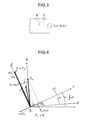
- FIG. 3 is a diagram of a single-phase basic equivalent circuit of the power conversion controlling apparatus of the present invention.
- FIG. 4 is a diagram of relationships (in consideration of circuit resistance) among biaxial voltage vectors V ⁇ and V ⁇ , biaxial current vectors I ⁇ and I ⁇ , and an AC electromotive force E a of the power conversion controlling apparatus of the present invention
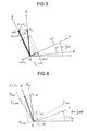
- FIG. 5 is a diagram of relationships (without consideration of circuit resistance) among the biaxial voltage vectors V ⁇ and V ⁇ , the biaxial current vectors I ⁇ and I ⁇ , and the AC electromotive force E a of the power conversion controlling apparatus of the present invention
- FIG. 6 is a diagram of relationships between phase angles and ⁇ - ⁇ axis components in rotational coordinate transformation of the power conversion controlling apparatus of the present invention.
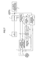
- FIG. 7 is a block diagram of the power conversion controlling apparatus of the present invention, in which a frequency computing unit includes LPF;
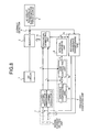
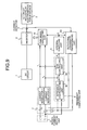
- FIG. 8 is a block diagram of the power conversion controlling apparatus of the present invention in which the frequency computing unit includes an impedance compensating unit;
- FIG. 9 is a block diagram of the power conversion controlling apparatus of the present invention in which I ⁇ is input into the impedance compensating unit;
- FIG. 10 is a block diagram of the power conversion controlling apparatus of the present invention in which V ⁇ is input into the impedance compensating unit;
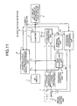
- FIG. 11 is a block diagram of the power conversion controlling apparatus of the present invention in which an inverter output voltage orthogonal biaxial transforming unit is provided in;
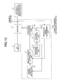
- FIG. 12 is a block diagram of the power conversion controlling apparatus of the present invention in which an operating frequency of the inverter is input into a biaxial current setting unit;
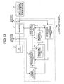
- FIG. 13 is a block diagram of the power conversion controlling apparatus of the present invention in which a DC voltage of the inverter is input into the biaxial current setting unit;
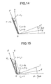
- FIG. 14 is diagram of relationships between voltage and current vectors during power factor 1 operation at an output end of the inverter of the power conversion controlling apparatus of the present invention
- FIG. 15 is diagram of relationships between voltage and current vectors during power factor 1 operation at an electromotive force end of an AC circuit of the power conversion controlling apparatus of the present invention
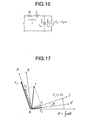
- FIG. 16 is a diagram of a single-phase equivalent circuit when an electromotive force source involving an excitation circuit is connected to the AC circuit;
- FIG. 17 is a diagram of voltage and current vectors when the electromotive force source involving the excitation circuit is connected to the AC circuit;
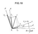
- FIG. 18 is a diagram of voltage and current vectors during power factor 1 operation at the electromotive force end when the electromotive force source involving the excitation circuit is connected to the AC circuit;
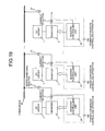
- FIG. 19 is a diagram of the power conversion controlling apparatuses in which a plurality of inverters are connected;
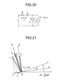
- FIG. 20 is a diagram of a single-phase equivalent circuit when an AC load including a capacitor is connected to the AC circuit;
- FIG. 21 is a diagram of voltage and current vectors during power factor 1 operation at a capacitor end when the AC load including the capacitor is connected to the AC circuit;
- FIG. 22 is a block diagram of Example 1 when a synchronous motor is connected to the AC circuit in the power conversion controlling apparatus of the present invention
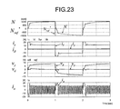
- FIG. 23 is a diagram of simulation analysis results for the block diagram of Example 1 when the synchronous motor is connected to the AC circuit in the power conversion controlling apparatus of the present invention
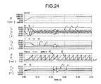
- FIG. 24 is a diagram of simulation analysis results of transient phase follow-up control for the block diagram of Example 1 when the synchronous motor is connected to the AC circuit in the power conversion controlling apparatus of the present invention
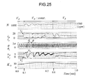
- FIG. 25 is a diagram of simulation analysis results of phase follow-up control by V ⁇ for the block diagram of Example 1 when the synchronous motor is connected to the AC circuit in the power conversion controlling apparatus of the present invention
- FIG. 26 is a diagram of experimental results of Example 1 when the synchronous motor is connected to the AC circuit in the power conversion controlling apparatus of the present invention
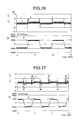
- FIG. 27 is a diagram of experimental results of Example 1 when the synchronous motor is connected to the AC circuit in the power conversion controlling apparatus of the present invention
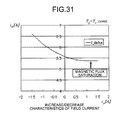
- FIG. 31 is a diagram of experimental characteristics of Example 1 when the synchronous motor is connected to the AC circuit in the power conversion controlling apparatus of the present invention
- FIG. 34 is a diagram of experimental results when demagnetization operation is performed at the rated DC voltage in Example 1 when the synchronous motor is connected to the AC circuit in the power conversion controlling apparatus of the present invention
- FIG. 35 is a diagram of experimental results when a load torque is abruptly changed between total load and no load in Example 1 when the synchronous motor is connected to the AC circuit in the power conversion controlling apparatus of the present invention
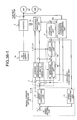
- FIG. 36-1 is a diagram of a power conversion system in Example 1 when a plurality of synchronous motors are driven;
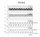
- FIG. 36-2 is a diagram of operation waveforms when synchronous motors have different ratings in the power conversion system shown in FIG. 36-1 ;
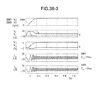
- FIG. 36-3 is a diagram of simulation analysis results when synchronous motors have the same load torque in the power conversion system shown in FIG. 36-1 ;
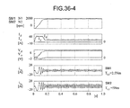
- FIG. 36-4 is a diagram of simulation analysis results when synchronous motors have different load torques in the power conversion system shown in FIG. 36-1 ;
- FIG. 37 is a block diagram of Example 2 when the synchronous motor is connected to an AC circuit in a power conversion controlling apparatus of the present invention
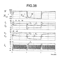
- FIG. 38 is a diagram of simulation analysis results for the block diagram of Example 2 when the synchronous motor is connected to the AC circuit in the power conversion controlling apparatus of the present invention
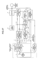
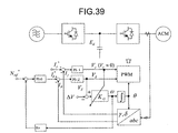
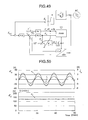
- FIG. 39 is a block diagram of Example 3 when the synchronous motor is connected to an AC circuit in a power conversion controlling apparatus of the present invention.
- FIG. 40 is a block diagram of Example 4 when the induction motor is connected to an AC circuit in a power conversion controlling apparatus of the present invention
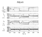
- FIG. 41 is a diagram of simulation analysis results for the block diagram of Example 4 when the induction motor is connected to the AC circuit in the power conversion controlling apparatus of the present invention
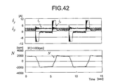
- FIG. 42 is a diagram of experimental results of Example 4 when the induction motor is connected to the AC circuit in the power conversion controlling apparatus of the present invention.
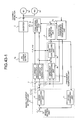
- FIG. 43-1 is a diagram of a power conversion system when a plurality of induction motors are driven in the system in Example 4;
- FIG. 43-2 is a diagram of simulation analysis results when induction motors have the same load torque in the power conversion system shown in FIG. 43-1 ;
- FIG. 43-3 is a diagram of simulation analysis results when induction motors have different load torques in the power conversion system shown in FIG. 43-1 ;
- FIG. 44 is a block diagram of Example 5 when the induction motor is connected to an AC circuit in a power conversion controlling apparatus of the present invention
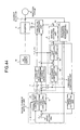
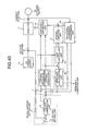
- FIG. 45 is a block diagram of Example 6 when the AC power supply is connected to an AC circuit and the DC power supply is connected to a DC circuit in a power conversion controlling apparatus of the present invention
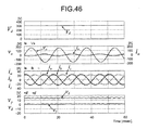
- FIG. 46 is a diagram of simulation analysis results for the block diagram of Example 6 when the AC power supply is connected to the AC circuit and the DC power supply is connected to the DC circuit in the power conversion controlling apparatus of the present invention
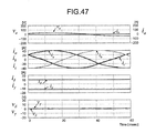
- FIG. 47 is a diagram of simulation analysis results when the AC power supply is cut off in the block diagram of Example 6 when the AC power supply is connected to the AC circuit and the DC power supply is connected to the DC circuit in the power conversion controlling apparatus of the present invention;
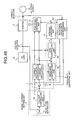
- FIG. 48 is a block diagram of Example 7 when the AC power supply is connected to an AC circuit and the DC power supply is connected to a DC circuit in a power conversion controlling apparatus of the present invention
- FIG. 49 is a block diagram of Example 8 when the AC power supply is connected to an AC circuit and the DC power supply is connected to a DC circuit in a power conversion controlling apparatus of the present invention
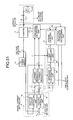
- FIG. 50 is a diagram of experimental results of Example 7 when the AC power supply is connected to the AC circuit and a resistor is connected to the DC circuit as a DC load in the power conversion controlling apparatus of the present invention
- FIG. 51 is a block diagram of Example 9 when an AC load including a capacitor is connected to an AC circuit in a power conversion controlling apparatus of the present invention.
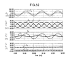
- FIG. 52 is a diagram of simulation analysis results for the block diagram of Example 9 when the AC load including the capacitor is connected to the AC circuit in the power conversion controlling apparatus of the present invention.
- a power conversion controlling apparatus that controls the power conversion of a power conversion controlling apparatus, a power conversion controlling method, and a power conversion controlling program according to the present invention will be described below with reference to attached drawings.
- the present invention is not limited by such embodiments. Components in the embodiments shown below include those that can easily be conceived by a person skilled in the art or are substantially identical.
- a power converting unit that exchanges power between DC and AC includes an inverter that converts DC power into AC power and an AC-DC converter that converts AC power into DC power.
- inverters are mainly exemplified as the power converting unit in embodiments that follow, the present invention is also applicable to AC-DC converters.
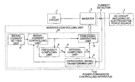
- FIG. 1 is a diagram of a basic configuration of a power conversion controlling apparatus according to the present invention.
- the power conversion controlling apparatus according to a first embodiment is used to control an inverter that performs power conversion between DC and AC when an AC circuit has an electromotive force source.
- numeral 1 is a DC circuit
- numeral 2 is an inverter connected between the DC circuit 1 and an AC circuit 3 to exchange power between DC and AC with a switching device
- numeral 3 is the AC circuit including the electromotive force source (hereinafter also called an “AC circuit”)
- numeral 100 is a power conversion controlling apparatus.
- numeral 2 is illustrated as an inverter, but numeral 2 may be an AC-DC converter that performs AC-DC conversion depending on types of the connected DC circuit 1 and the AC circuit 3 .
- the DC circuit 1 is a circuit including a DC power supply, a DC load, or a capacitor.
- the AC circuit 3 including an AC electromotive force source is an AC circuit having an electromotive force source such as an AC motor, an AC generator, an AC power supply, and a load including a capacitor.
- the power conversion controlling apparatus 100 includes a current detector 4 that detects a current flowing through the AC circuit 3 to output a detection signal and an inverter controlling unit 20 that controls the inverter 2 based on the detection signal of the current detector 4 .
- the inverter controlling unit 20 includes an orthogonal biaxial transforming unit 5 , a biaxial current setting unit 6 , a biaxial current controlling unit 7 , a frequency computing unit 8 , an integral computing unit 9 , and a PWM signal generating unit 10 .
- the inverter controlling unit 20 may be configured by a microcomputer, DSP or the like and a power conversion controlling program may be executed by a computer to implement functions of the orthogonal biaxial transforming unit 5 , biaxial current setting unit 6 , biaxial current controlling unit 7 , frequency computing unit 8 , integral computing unit 9 , and PWM signal generating unit 10 .
- the frequency computing unit 8 determines an operating frequency of the inverter 2 to output an operating frequency signal ⁇ e .
- the frequency computing unit 8 determines the operating frequency signal ⁇ e of the inverter 2 in such a way that the amplitude command value corresponding to a reactive component of current among the amplitude command values output by the biaxial current controlling unit 7 is led to zero. Details of this principle will be described later.
- the integral computing unit 9 computes a phase angle signal ⁇ e by integration from the output of the frequency computing unit 8 and outputs the phase angle signal ⁇ e .
- the orthogonal biaxial transforming unit 5 computes a biaxial current of an active component and a reactive component by orthogonal biaxial transformation from the detection signal of the current detector 4 and the phase angle signal ⁇ e of the frequency computing unit 8 to output the biaxial current.
- the biaxial current setting unit 6 determines a command value of the biaxial current to output the command value.
- the biaxial current controlling unit 7 computes an amount of error from a difference between the output of the orthogonal biaxial transforming unit 5 and that of the biaxial current setting unit 6 to output an amplitude command value according to the amount of error for each biaxial component.
- the PWM signal generating unit 10 generates a PWM signal, which is a control signal to be provided to the inverter 2 , based on the output of the biaxial current controlling unit 7 and the phase angle signal ⁇ e of the integral computing unit 9 to supply the PWM signal to the inverter 2 .
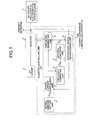
- FIG. 2-1 is a diagram of the configuration of the power conversion controlling apparatus that performs a frequency computation using an amplitude command value (an inverter voltage command value in a broad sense) in the power conversion controlling apparatus in FIG. 1 .
- the power conversion controlling apparatus 100 in FIG. 2-1 depicts a concrete configuration example when a three-phase (UVW) AC load including an AC electromotive force source is connected to the AC circuit 3 in the power conversion controlling apparatus in FIG. 1 .
- the inverter 2 is a three-phase inverter and can be configured by a bridge circuit including a switching device such as an IGBT.
- the current detector 4 detects at least two phases of current flowing through the AC circuit 3 as a detection signal.
- a rotational coordinate transforming unit 5 a which is the orthogonal biaxial transforming unit, performs a ⁇ - ⁇ transformation of a detection signal detected by the current detector 4 in which the active component is set to a ⁇ -axis component and the reactive component is set to a ⁇ -axis component in synchronization with the operating frequency of the inverter 2 to output transformed biaxial amounts I ⁇ and I ⁇ to the biaxial current controlling unit 7 .
- the biaxial current controlling unit 7 generates biaxial control voltages of the inverter 2 , that is, amplitude command values V ⁇ and V ⁇ of the inverter 2 via two sets of current regulators 1 and 2 included in the biaxial current controlling unit 7 in such a way that the transformed biaxial amounts I ⁇ and I ⁇ match biaxial current command values I ⁇ * and I ⁇ * output by the biaxial current setting unit 6 .
- the frequency computing unit 8 determines the operating frequency signal ⁇ e of the inverter 2 in such a way that the uniaxial voltage value V ⁇ of the amplitude command values V ⁇ and V ⁇ becomes zero, and the integral computing unit 9 obtains the operating phase angle signal ⁇ e of the inverter 2 by integrating the operating frequency signal ⁇ e to perform the rotational coordinate transformation of the AC current and also causes the PWM signal generating unit 10 to generate a PWM signal (v u , v v , v w ), which is a control signal of the inverter 2 , by trigonometry or the like from biaxial voltage amounts V ⁇ and V ⁇ to operate the inverter 2 . Accordingly, it becomes possible to control power exchange between AC and DC only by detection control of current flowing through the AC circuit without acquiring phase information of an AC electromotive force source of the AC circuit 3 by a sensor and using circuit constants.
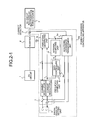
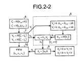
- FIG. 2-2 is a control sequence diagram of the power conversion controlling apparatus in FIG. 2-1 .
- FIG. 3 is a diagram of a single-phase equivalent circuit when a synchronous motor and an AC power supply are connected as an example that an electromotive force source in the AC circuit 3 is included.
- R denotes a circuit resistor
- L denotes a circuit inductance
- E a denotes a transformation amount of rotational coordinates of an AC electromotive force source ea.
- V ⁇ is a voltage command value component proportional to an output voltage vector of the inverter 2
- V ⁇ is a voltage command value component orthogonal to this axis
- I ⁇ is the active component of current of a current vector
- I ⁇ is the reactive component of current.
- FIG. 4 depicts a vector diagram when the component voltage V ⁇ of the ⁇ axis is zero in a stationary state with the biaxial component voltages V ⁇ and V ⁇ , biaxial component currents I ⁇ and I ⁇ , and AC electromotive force E a based on the formula (3).
- coordinate axes of the biaxial component voltages V ⁇ and V ⁇ are the ⁇ axis and ⁇ axis
- the voltage vector E a of the AC electromotive force is the q axis
- a magnetic flux axis orthogonal to the q axis is the d axis.
- ⁇ denotes a phase angle between two coordinate axes.
- FIG. 5 depicts a vector diagram when a voltage drop by circuit resistance is ignored.
- power P a from the inverter 2 is given by the formula (6) shown below, which is represented by a sine-wave function of an angle of phase difference or load angle ⁇ .
- the angular frequency ⁇ can be approximated by the formula (12) shown below and is proportional to V ⁇ . [Formula 12] ⁇ V ⁇ /k ⁇ (12)
- the integral computing unit 9 can calculate a rotational phase angle ⁇ e of the inverter 2 in synchronization with the rotational phase angle of the AC electromotive force source according to the formula (14) shown below with the operating frequency ⁇ e of the inverter of the formula (13) as an input.
- ⁇ e ⁇ e dt (14)
- the rotational phase angle ⁇ e obtained from the frequency computation does not match an appropriate phase angle ⁇ synchronized with the rotation phase angle of the AC electromotive force source, the ⁇ -axis component voltage V ⁇ of the output voltage vector V of the inverter 2 shown in FIG. 6 appears.
- This V ⁇ takes a negative value when the phase angle ⁇ e obtained from the computation lags and a positive value when the phase angle leads.
- the rotational phase angle ⁇ e obtained from the computation can be led to the appropriate rotational phase angle ⁇ by adjusting the value of K G in the formula (13) so that the value of V ⁇ becomes zero through a PI controller or the like based on the sign of the ⁇ -axis component voltage V ⁇ .
- the power conversion controlling apparatus includes the frequency computing unit 8 that determines an operating frequency of the inverter 2 to output the operating frequency signal ⁇ e , the integral computing unit 9 that determines a phase angle signal ⁇ e by integration from the output of the frequency computing unit 8 to output the phase angle signal, the orthogonal biaxial transforming unit 5 that computes a biaxial current of the active component and reactive component by orthogonal biaxial transformation from a detection signal of the current detector 4 and the phase angle signal ⁇ e of the frequency computing unit 8 to output the biaxial current, the biaxial current setting unit 6 that determines a command value of the biaxial current to output the command value of the biaxial current, the biaxial current controlling unit 7 that computes an amount of error from a difference between output of the orthogonal biaxial transforming unit 5 and that of the biaxial current setting unit 6 to output an amplitude command value according to the amount of error for each biaxial component, and the PWM signal generating unit 10 that generates a control signal to be provided to the inverter 2
- the power conversion controlling apparatus can be used for general purposes because no AC circuit constant is used.
- the frequency computing unit 8 may use a value obtained by multiplying the constant by a gain as the operating frequency ⁇ e of the inverter 2 . Since the amplitude command value corresponding to the active component of current among the amplitude command values output by the biaxial current controlling unit 7 takes a constant value if the AC electromotive force source has a constant frequency like a commercial power supply, instead of using the amplitude command value as an input into the frequency computing unit 8 , the corresponding constant value may be used as an input to be multiplied by a gain in such a way that the amplitude command value corresponding to the reactive component of current among the amplitude command values output by the biaxial current controlling unit 7 becomes zero before being selected as the operating frequency ⁇ e of the inverter 2 .
- the control system can thereby be simplified.
- a power conversion controlling apparatus uses, in the frequency computing unit 8 (gain controlling unit 8 a ) of the power conversion controlling apparatus in FIG. 2-1 , a value obtained by multiplying the amplitude command value corresponding to the active component of current among the amplitude command values output by the biaxial current controlling unit 7 by a gain, that obtained by multiplying a time variation reduced value of the amplitude command value corresponding to the active component of current by a gain, or a time variation reduced value of such a gain multiplied value is selected as the operating frequency ⁇ e of the inverter 7 .
- the operating frequency ⁇ e of the inverter 2 is determined by multiplying the amplitude command value corresponding to the active component of current by a gain among the amplitude command values output from the biaxial current controlling unit 7 .
- a time variation reduced value of the amplitude command value corresponding to the active component of current may also be used.
- a time variation reduced value of the gain multiplied value may also be determined as the operating frequency of the inverter 2 . Time variation reduction at this time is intended to prevent control instability caused by a rapid change of the operating frequency of the AC circuit 3 compared with a case when no such rapid change occurs.
- FIG. 7 is a diagram exemplifying the power conversion controlling apparatus when an LPF (low-pass filter) is provided in the frequency computing unit 8 to reduce time variations.
- V ⁇ and V ⁇ are output from the biaxial current controlling unit 7 and include some ripple components and thus, if output from the gain controlling unit 8 a is directly used as the operating frequency and phase control, which is an integral thereof, operations may become unstable due to an influence of ripples.
- output of the gain controlling unit 8 a is used, after being caused to pass through an LPF (low-pass filter) 8 c , as the operating frequency and a control phase signal, which is an integral thereof.
- the filter factor of the LPF 8 c may be set, for example, as k/(1+ ⁇ ).
- V ⁇ output by the biaxial current controlling unit 7 may also be caused to pass through the LPF (low-pass filter) before being input into the frequency computing unit 8 to reduce the influence of ripple components.
- LPF low-pass filter
- the power conversion controlling apparatus uses, among the amplitude command values output by the biaxial current controlling unit 7 , a value obtained by multiplying the amplitude command value corresponding to the active component of current by a gain, that obtained by multiplying a time variation reduced value of the amplitude command value corresponding to the active component of current by a gain, or time variation reduced values of such gain multiplied values is selected as the operating frequency of the inverter 2 and therefore, stable operation can be performed even if the operating frequency of the AC circuit changes rapidly.
- FIG. 8 is a diagram of an AC power conversion controlling apparatus according to a third embodiment.
- the same numerals are attached to components having functions equivalent to those of components in FIG. 2-1 to omit a description of common portions.
- the power conversion controlling apparatus according to the third embodiment has a configuration in which an impedance compensating unit is provided in the frequency computing unit 8 .
- the frequency computing unit 8 is provided with an impedance compensating unit 8 b that outputs a compensation value for compensating for a stationary or transient voltage drop in a line impedance portion when an amplitude command value corresponding to the active component of current among the amplitude command values output by the biaxial current controlling unit 7 changes.
- the frequency computing unit 8 adopts a value obtained by multiplying an added value of an amplitude command value corresponding to the active component of current or a time variation reduced value of the amplitude command value by, for example, an LPF (not shown) and an output of the impedance compensating unit 8 b by a gain or a time variation reduced value of the gain multiplied value by, for example, an LPF as the operating frequency of the inverter 2 .
- phase angle ⁇ e obtained from the formulas (13) and (14) can easily be made to match the rotational phase angle ⁇ of the AC electromotive force source if the term of E a in the formula (2) is large.
- E a in the formula (2) becomes smaller, it becomes more difficult to perform follow-up control of the phase angle ⁇ e obtained by computation to an appropriate phase angle ⁇ .
- frequency phase follow-up properties can be improved by removing terms due to an impedance voltage drop shown in the first and second terms from V ⁇ in the formula (2).
- the proportional gain K G in the formula (18) will be an approximate value of the appropriate proportional gain K G in the formula (13). If, in the formula (15), E a cos ⁇ is large, the voltage drop RI ⁇ by resistance can be ignored and also the second term dI ⁇ /dt, which is a transient term, can be ignored due to a near stationary state. Therefore, the computed phase angle ⁇ e can be made to match the appropriate phase angle ⁇ by tuning the proportional gain K G near the approximate value according to the formula (18) so that the ⁇ -axis component voltage V ⁇ of the inverter output voltage vector V becomes zero.
- the impedance compensating unit 8 b may compute the compensation value using the active component of current or a command value of the active component of current.
- the configuration of the power conversion controlling apparatus in this case is shown in FIG. 9 . More specifically, the resistance drop term and the differential drop term are included in ⁇ V in the formula (19) to which a compensating term of impedance voltage drop is added to change the form to the formula (20) shown below and the impedance compensating unit 8 b compensates for the impedance voltage drop based on the active component of current I ⁇ or its setting value I ⁇ *.
- the impedance compensating unit 8 b may also compute the compensation value by reducing time variations of the active component of current or the command value of the active component of current. Control instability caused by a rapid change of the operating frequency of the AC circuit 3 compared with a case when no such rapid change occurs is thereby prevented. For example, if the operating frequency ⁇ e of the AC circuit 3 is extremely low, the current value detected by the current detector 4 will be small and the variation width ratio will be high in the detected current value. Thus, the variation ratio will also be high in the active component of current input into the impedance compensating unit 8 b and current variations may excessively affect the compensation in the impedance compensating unit 8 b . Therefore, by adding a filter for reducing time variations to a portion of the impedance compensating unit 8 b where the active component of current is input, the frequency phase follow-up properties can be improved.
- the impedance compensating unit 8 b may compute the compensation value using the amplitude command value corresponding to the reactive component of current among the amplitude command values output by the biaxial current controlling unit 7 .
- k ⁇ is a proportionality factor for providing an appropriate compensation amount.
- FIG. 11 is a diagram of a power conversion controlling apparatus according to a fourth embodiment.
- the same numerals are attached to components having functions equivalent to those of components in FIG. 2-1 to omit a description of common portions.
- the power conversion controlling apparatus according to the fourth embodiment includes an AC side voltage detector 21 that detects an output voltage of the inverter 2 and an inverter output voltage orthogonal biaxial transforming unit 22 that performs an orthogonal biaxial transformation of an output voltage of the inverter 2 .
- the inverter output voltage orthogonal biaxial transforming unit 22 computes a biaxial voltage by means of orthogonal biaxial transformation from the output voltage of the inverter 2 detected by the AC side voltage detector 21 and the phase angle signal ⁇ e of the integral computing unit 9 to output a signal of the amount corresponding to the amplitude command values V ⁇ and V ⁇ output by the biaxial current controlling unit 7 for each biaxial component to the frequency computing unit 8 .
- the frequency computing unit 8 computes the operating frequency ⁇ e of the inverter 2 by replacing the amplitude command value with a signal value of the inverter output voltage orthogonal biaxial transforming unit 22 for each biaxial component and using these values.
- FIG. 12 is a diagram of a power conversion controlling apparatus in a fifth embodiment.
- the same numerals are attached to components having functions equivalent to those of components in FIG. 2-1 to omit a description of common portions.
- the biaxial current setting unit 6 computes a command value of the active component of current using the operating frequency ⁇ e of the inverter 2 output by the frequency computing unit 8 .
- a rotational angular velocity ⁇ me of the AC machine may be computed by the formula (22) shown below using the operating frequency ⁇ e of the inverter 2 .
- a speed control loop can be formed, without using a speed sensor, by using an output of a speed regulator as the command value of the active component of current via the speed regulator by comparing with a speed setting value of the AC machine based the operating frequency ⁇ e of the inverter 2 .
- the operating frequency ⁇ e of the inverter 2 is not limited to speed settings of the AC machine and can be used also for settings of the reactive component of current in, for example, reactive power compensation.
- FIG. 13 is a diagram of a power conversion controlling apparatus according to a sixth embodiment.
- the same numerals are attached to components having functions equivalent to those of components in FIG. 2-1 to omit a description of common portions.
- the biaxial current setting unit 6 computes the command value of the active component of current using the DC side voltage value of the inverter 2 detected by a voltage detector 15 . If power is exchanged between the DC circuit 1 and the AC circuit 3 when the voltage of the DC circuit 1 is not determined, a DC voltage control loop can be formed by detecting the DC voltage, comparing the DC voltage with the DC voltage setting value, and using the output of the voltage regulator as the command value of the active component of current via the voltage regulator.
- the DC circuit 1 is a DC load accompanied by DC voltage variations caused by a DC current, a DC power supply such as solar cells and fuel cells, or a DC circuit to which only a capacitor is connected such as an active filter and a reactive power compensating unit.
- the power factor is set arbitrarily in the power conversion controlling apparatus shown in FIG. 2-1 by adjusting the command value of the reactive component of current of the biaxial current setting unit 6 .
- the reactive component of current By regulating the reactive component of current, power factor 1 control at an output end of the inverter 2 , power factor 1 control at an AC electromotive force source end of the AC circuit 3 , and an operation as a reactive power compensating apparatus can be caused.
- the biaxial current setting unit 6 determines the command value of the reactive component of current so that the power factor at the output end of the inverter 2 becomes 1.
- FIG. 14 is a diagram of relationships between voltage and current vectors during power factor 1 operation at the output end of the inverter of the power conversion controlling apparatus according to the seventh embodiment.
- the rotational phase angle ⁇ e of the inverter 2 can be made to match the rotational phase angle ⁇ of the frequency of the AC electromotive force, like the voltage vector V ⁇ , the current vector becomes a ⁇ -axis component current I ⁇ only when I ⁇ is controlled to 0 and I ⁇ to be constant so that the power factor at an inverter output end can be controlled to be 1. Accordingly, the power conversion controlling apparatus can be operated at high efficiency.
- the biaxial current setting unit 6 determines the command value of the reactive component of current so that the power factor at the AC electromotive force source end of the AC circuit 3 becomes 1. By setting the command value in such a way that the power factor at the AC electromotive force end becomes 1, response characteristics of an AC motor can further be enhanced.
- FIG. 15 is a diagram of relationships between voltage and current vectors during power factor 1 operation at an electromotive force end of the AC circuit 3 of the power conversion controlling apparatus.
- an induced voltage vector E a of an AC machine matching the q axis and the current vector can be matched by giving the setting value I ⁇ * of the ⁇ -axis component current I ⁇ by the formula (23) shown below, and can realize a power factor 1 operation at the electromotive force end. Maximum power can thereby be supplied to the AC electromotive force source and thus, high-speed response characteristics can be given.
- I ⁇ I ⁇ tan ⁇ (23)
- the setting value I ⁇ * of the ⁇ -axis component current I ⁇ is given as a product of I ⁇ 2 , which is an amount of the square of ⁇ -axis component current, and (L/k ⁇ ). Since, as shown in the formula (10), k ⁇ is a proportionality constant proportional to the magnetic flux, k ⁇ is known and a constant value and 1/k ⁇ is also a constant value.
- the AC circuit 3 may be made to be a circuit including one or a plurality of AC machines. If the AC circuit 3 is configured by a circuit including one AC machine, power can be exchanged with the DC circuit 1 by connecting the AC machine as the electromotive force source. If the AC circuit 3 is configured by a circuit including a plurality of AC machines, the plurality of AC machines are connected to one inverter in parallel and the plurality of AC machines are considered virtually to be one AC machine for operation/control.
- a synchronous machine, a reluctance machine, an induction machine, or a synchronous induction machine can be used as the AC machine. If a synchronous machine is configured as the AC machine, a wide range of synchronous machines from ones having a field winding including saliency and non-salient poles to permanent-magnet synchronous machines can be applied. If a reluctance machine is configured as the AC machine, reluctance machines including neither field winding nor magnet become applicable by setting the reactive component of current and active component of current appropriately.
- FIG. 16 depicts a single-phase equivalent circuit when viewed from a stator side of an induction machine.
- R denotes a wire wound resistor
- L a wire wound inductance
- E an electromotive force source proportional to the frequency
- ⁇ and Lm shows an exciting inductance.
- FIG. 17 is a diagram of voltage and current vectors when the electromotive force source involving an excitation circuit is connected to the AC circuit.
- the output voltage vector of the inverter 2 is assumed to have only a ⁇ -axis component and voltage and current vectors when a current vector obtained by adding a d-axis exciting component current Id to a ⁇ -axis component current I ⁇ is I are shown.
- the current vector I can be decomposed into the ⁇ -axis component current I ⁇ and the ⁇ -axis component current I ⁇ , forming the exemplified relationships.
- magnetization can be caused by flowing a lagging reactive component of current I ⁇ of the biaxial component current in the power conversion controlling apparatus, a high torque can be caused without increasing the active component of current I ⁇ significantly. Also, demagnetization can be caused by flowing a leading reactive component of current I ⁇ , enabling high-speed operation control without raising the voltage.
- the power conversion controlling apparatus can be controlled without being affected by magnetization/demagnetization control by the reactive component of current I ⁇ because sensorless control of the present invention does not depend on any estimation method using a motor model even though the magnetic flux model of the motor is unknown.
- sensorless control of the present invention does not depend on any estimation method using a motor model even though the magnetic flux model of the motor is unknown.
- FIG. 19 is a diagram of the power conversion controlling apparatuses in which a plurality of inverters are connected. FIG. 19 can suitably be used when only weak electric power systems are interconnected. Loads are connected to a common bus 30 and the inverter 2 is connected to the common bus 30 via an interconnecting reactor 31 .
- FIG. 20 is a single-phase equivalent circuit, and R denotes a wire wound resistor, L a wire wound inductance, C a capacitor, and E a a load connected to the capacitor in parallel.
- FIG. 21 depicts a relationship diagram of voltage and current vectors with respect to the ⁇ - ⁇ axis and the q-d axis when a current in phase with the capacitor terminal voltage flows through the load.
- the leading reactive component of current I d must be flown and the resultant current vector I of such current vectors can be decomposed into the ⁇ -axis component current I ⁇ and the ⁇ -axis component current I ⁇ , forming the exemplified relationships.
- power exchange between DC and AC that is, power conversion when the AC circuit that can exchange active power between the AC electromotive force source and inverter output can be performed.
- An AC power supply failure state in which some failure occurs in a commercial power supply or a generator constituting the AC power supply can also be detected by the power conversion controlling apparatus.
- the DC circuit 1 of the power conversion controlling apparatus may be, for example, a circuit including a capacitor, a DC power supply, or a DC load. If the DC circuit 1 is configured with the circuit including a capacitor, reactive power can be exchanged between the DC circuit side and AC circuit side even in a state in which only a capacitor is connected on the DC circuit side and therefore, the apparatus can be operated as a reactive power compensating apparatus or an active filter.
- the DC circuit 1 is configured with the circuit including the DC power supply, this means that power is exchanged from the DC power supply to the AC power supply.
- the DC power supply can be used as a drive energy source of an inverter and, if an AC generator or a commercial power supply is connected to the AC circuit 3 , the DC power supply can be used as an energy source to transfer power to the AC circuit side.
- the DC power supply can be used as an energy source to transfer power to the AC circuit side.
- the DC circuit 1 is configured with the circuit including a DC load, power can be supplied from a generator or AC power supply of the AC circuit to the DC load in the DC circuit.
- the present invention is not limited to the above first to tenth embodiments and can be carried out by combining each of the first to tenth embodiments.
- the above embodiments have been described using a three-phase AC, but the present invention is not limited to this and is applicable to any two-phase AC or higher. Examples 1 to 9 of power conversion control systems to which the power conversion controlling apparatuses according to the first to tenth embodiments are applied will be described below.
- FIG. 22 is a diagram of a power conversion control system according to Example 1.
- the power conversion control system shown in FIG. 22 performs speed control of a synchronous motor 3 b without using a rotational position sensor or a speed sensor by connecting the synchronous motor 3 b as an AC machine including an electromotive force source to the AC circuit 3 from a DC power supply 1 a , which is the DC circuit 1 , via the inverter 2 .
- a current flowing through the synchronous motor 3 b is detected by the current detector 4 .
- a coordinate transformation is performed by the rotational coordinate transforming unit 5 a , which is the orthogonal biaxial transforming unit 5 , and voltage command values (that is, amplitude command values) V ⁇ and V ⁇ are generated via the biaxial current controlling unit 7 so that rotational coordinate-transformed biaxial amounts I ⁇ and I ⁇ match corresponding biaxial current setting values I ⁇ * and I ⁇ * respectively to output the voltage command values to the PWM signal generating unit 10 and the frequency computing unit 8 .
- the PWM signal generating unit 10 generates a PWM signal to control the inverter 2 .
- the amplitude command values V ⁇ and V ⁇ are at the same time used by the gain controlling unit 8 a of the frequency computing unit 8 to determine the operating frequency ⁇ e of the inverter by multiplying the amplitude command value V ⁇ by a gain so that V ⁇ becomes zero.
- the phase angle signal ⁇ e made to match the phase angle ⁇ of the internal electromotive force of the synchronous motor 3 b is obtained.
- the impedance compensating unit 8 b is effective for compensating for being incapable of controlling V ⁇ to zero when the reference value I ⁇ * of the active component of current changes markedly due, for example, to acceleration or deceleration.
- the case is shown here in which a compensation is made based on the active component of current command value I ⁇ *.
- the active component of current command value I ⁇ * is obtained from an output of a speed controlling unit 12 causing an estimated speed value obtained from the operating frequency ⁇ e of the inverter 2 by a speed converting unit 11 and a speed setting reference value to match.
- the reactive component of current command value I ⁇ * is set to zero.
- the phase angle ⁇ e determined by a control loop is used as a reference phase of coordinate transformation in the rotational coordinate transforming unit 5 a and the PWM signal generating unit 10 .
- FIG. 23 depicts operation waveforms of simulation analysis performed when the DC operating voltage of the inverter is made to operate at 300 V using a permanent-magnet synchronous motor of 2.2 kW with four poles in the power conversion control system according to Example 1 ( FIG. 22 ).
- Circuit constants include an armature resistance of 1 ⁇ , an inductance of 10 mH, an electromotive force coefficient of 200 V/krpm, and a moment of inertia of 0.01 kgm 2 .
- FIG. 23 depicts velocity response waveforms when the speed setting value is changed between +1000 rpm and ⁇ 1000 rpm in a 0.5 Hz cycle.
- the active component of current I ⁇ has values drifting up to limiting values due to a moment of inertia of the motor in acceleration and deceleration sections and is a constant load current during normal operation. It can also be verified that the setting value I ⁇ of the reactive component of current is controlled to zero and the amplitude command value V ⁇ is also controlled to zero and, as a result, normal rotation and reverse rotation operations can be performed with power factor 1 . Meanwhile, as shown in the formula (12), the amplitude command value V ⁇ can be verified to make the same change as the number of revolutions proportional to the frequency. i a in FIG. 23 denotes single-phase current waveforms.
- FIG. 25 depicts, for the same power conversion control system as that in Experiment 1 and circuit parameters of the synchronous motor 3 b , operation waveforms when input of the amplitude command value V ⁇ corresponding to the active component of current into the frequency computing unit 8 is fixed to a value of V ⁇ just before reaching 1000 rpm when the speed setting value reaches 1000 rpm and, after changing the speed setting value to 1500 rpm, input of the amplitude command value V ⁇ into the frequency computing unit 8 is again brought back to the value of V ⁇ computed in real time.
- FIG. 26 and FIG. 27 depict experimental results when normal rotation and reverse rotation operations were performed by changing the speed setting value between +2000 rpm and ⁇ 2000 rpm under no load at 150 V of the DC operating voltage of the inverter using a permanent-magnet synchronous motor of 0.5 kW with four poles.
- FIG. 26 depicts normal/reverse rotation operation waveforms when the speed control period for normal/reverse rotation operations is about 7 seconds and
- FIG. 27 depicts normal/reverse rotation operation waveforms when the speed control period for normal/reverse rotation operations is about 1 second.
- biaxial current vector control can be performed only by detection control of the AC current using neither position sensor nor speed sensor from a synchronous motor and normal rotation and reverse rotation operations can be performed with good response.
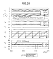
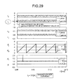
- FIG. 28 , FIG. 29 , and FIG. 30 depict operation waveforms when the command value I ⁇ * of the reactive component of current of the biaxial component current is changed during operation by setting the speed setting value to +1000 rpm under full-load torque at 200 V of the DC operating voltage of the inverter using a permanent-magnet synchronous motor of 0.5 kW and more specifically, operation waveforms when increase/decrease control of I ⁇ * is performed so that, relative to “0”, I ⁇ * increases to +1.0 A (magnetization current) or decreases to ⁇ 1.0 A (demagnetization current).
- FIG. 31 is a graph of variation characteristics of the active component of current I ⁇ with respect to the biaxial reactive component of current I ⁇ corresponding to a field current, showing that the magnetic flux is saturated because a decrease of I ⁇ when I ⁇ is increased is smaller than that of I ⁇ when I ⁇ is decreased. Since the present invention does not use such a magnetic flux model for sensorless control, it is clear that torque control can be performed without using any sensor with stability regardless of nonlinear characteristics.
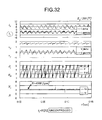
- FIG. 32 depict operation waveforms when the setting value is increased while keeping the reference value I ⁇ * of the biaxial reactive component of current unchanged at “0” under full-load torque at 200 V of the DC operating voltage of the inverter 2 using the permanent-magnet synchronous motor of 0.5 kW, confirming that control operation becomes unstable near 4000 rpm and thus, a still faster operation is impossible.
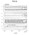
- FIG. 33 verifies that operations at 5000 rpm become possible by raising the DC voltage of the inverter to 260 V while keeping the reference value I ⁇ * unchanged at “0”. However, the DC voltage of the inverter is normally controlled to a rated value.
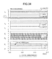
- FIG. 34 depicts experimental results verifying that operations at 5000 rpm can be performed while maintaining the DC voltage of the inverter constant at 200 V by changing the reference value I ⁇ * according to the speed reference and flowing a demagnetization current when the speed reference is raised.
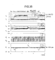
- FIG. 35 depict operation waveforms when the load torque is changed between full load and no load over time with low-speed rotation of 500 rpm of the reference speed at 200 V of the DC operating voltage of the inverter using the permanent-magnet synchronous motor of 0.5 kW, verifying from these experimental results that sensorless control of the present invention can perform operations with stability with respect to abrupt load torque variations at low speed.
- FIG. 36-2 depicts operation waveforms when two synchronous motors of rated 0.5 kW and 6 kW were driven by one inverter in the experiment. As shown in FIG. 36-2 , experimental results can verify that the two synchronous motors can be operated with stability even though they have different capacities.
- FIG. 36-3 and FIG. 36-4 depict operation waveforms by means of simulations when the two synchronous motors of rated 2.2 kW were driven by one inverter.
- FIG. 36-3 depicts simulation results when a load torque acting on each of the two synchronous motors is 5 Nm and FIG.
- 36-4 depicts simulation results when different load torques of 2.5 Nm and 5 Nm act on the synchronous motors.
- Each of the two synchronous motor models used for simulations has four poles, the armature resistance of 1 ⁇ , the inductance of 10 mH, the electromotive force coefficient of 200 V/krpm, and the moment of inertia of 0.01 kgm 2 and the DC operating voltage of the inverter is 300 V.
- FIG. 37 is a diagram of the configuration of a power conversion control system according to Example 2.
- the power conversion control system according to Example 2 shown in FIG. 37 has the reactive component of current I ⁇ * set through computation of the formula (24) based on the active component of current I ⁇ so that power factor 1 operation can be performed at an internal electromotive force end of the synchronous motor in the power conversion control system according to Example 1 ( FIG. 22 ).
- biaxial current vector control with the internal electromotive force of the motor as a reference can be performed only by AC current detection using neither position sensor nor speed sensor in the synchronous motor driving, power factor 1 operation can be performed at an internal electromotive force end of the synchronous motor, and normal rotation to reverse rotation operations and reverse rotation to normal rotation operations can continuously be controlled with still enhanced speed control response of the synchronous motor.
- FIG. 38 depicts simulation analysis results for the power conversion control system according to Example 2 ( FIG. 37 ). It can be verified that, as a result power factor 1 control being performed at the internal electromotive force end of the synchronous motor, normal rotation and reverse rotation operations can be performed in a short time compared with results of FIG. 23 where no power factor 1 control is performed.
- FIG. 39 depicts a concrete sensorless drive system of the synchronous motor of the power conversion control system of Example 1 ( FIG. 22 ) or Example 2 ( FIG. 37 ).
- a difference in correspondence to FIG. 22 and FIG. 37 is a difference whether the command value I ⁇ * of I ⁇ is zero or determined by the formula (24).
- the operating frequency ⁇ e of the inverter is calculated by adjusting the proportional gain K G for V ⁇ so that V ⁇ becomes zero.
- V ⁇ is used as an input into the gain controlling unit and ⁇ V denotes an impedance compensation amount by the formula (19) or (20).
- FIG. 40 is a diagram of a power conversion control system according to Example 4.
- FIG. 40 is a diagram after replacing the synchronous motor 3 b with an induction motor 3 c and setting the command value I ⁇ * of the reactive component of current to an exciting current value I 0 needed for induction motor driving being given by the formula (25) in the power conversion control system according to Example 1 ( FIG. 22 ).
- the rotational speed value of the induction motor can be computed approximately according to the formula (22) based on the operating frequency ⁇ e of the inverter.
- biaxial current vector control with the output voltage of the inverter as a reference can be performed only by AC current detection without using a speed sensor in induction motor driving and normal rotation to reverse rotation operations and reverse rotation to normal rotation operations of the induction motor can continuously be controlled.
- FIG. 41 depicts operation waveforms of simulation analysis performed when the DC operating voltage of the inverter is made to operate at 300 V using the induction motor of about 2.2 kW with four poles in the power conversion control system according to Example 4 ( FIG. 40 ).
- Circuit constants include a stator resistance of 0.294 ⁇ , a stator leakage inductance of 1.39 mH, a rotor resistance of 0.156 ⁇ , a rotor leakage inductance of 0.74 mH, an exciting inductance of 41 mH, and a moment of inertia of 0.01 kgm 2 .
- FIG. 42 depicts experimental results when normal rotation and reverse rotation operations were performed by changing the speed setting value between +2000 rpm and ⁇ 2000 rpm under no load at 150 V of the DC operating voltage of the inverter using a squirrel-cage induction motor of 0.75 kW with four poles.
- the setting value of the reactive component of current was set to 1.5 A for the exciting current of the induction motor. It can be verified that the active component of current has a large value due to the moment of inertia of the motor during reversal of normal/reverse rotation, but a small current value due to no load during steady operation. It can be verified from these results that, in the present invention, biaxial current vector control can be performed only by detection control of the AC current without using a speed sensor also for an induction motor and normal rotation and reverse rotation operations can be performed with good response.
- FIG. 43-1 Simulation analysis was performed in a power conversion system shown in FIG. 43-1 as a control example in which a plurality of induction motors of Experiment 4 ( FIG. 40 ) are driven.
- FIG. 43-2 and FIG. 43-3 depict operation waveforms by means of simulations when two induction motors of rated 2.2 kW were driven by one inverter.
- FIG. 43-2 depicts simulation results when a load torque acting on each of the two induction motors is 10 Nm
- FIG. 43-3 depicts simulation results when different load torques of 5 Nm and 10 Nm act on the induction motors.
- Each of the two induction motor models used for simulations has four poles, the stator resistance of 0.294 ⁇ , stator leakage inductance of 1.39 mH, rotor resistance of 0.156 ⁇ , rotor leakage inductance of 0.74 mH, exciting inductance of 41 mH, and moment of inertia of 0.01 kgm 2 and the DC operating voltage of the inverter is 300 V.
- FIG. 44 is a diagram of the configuration of a power conversion control system according to Example 5.
- FIG. 44 depicts that the command value I ⁇ * of the reactive component of current is determined through computation of the formula (27) based on the active component of current I ⁇ so that power factor 1 operation can be performed at the internal electromotive force end of the induction motor in the control system according to Example 4 ( FIG. 40 ).
- biaxial current vector control with the internal electromotive force of the motor as a reference can be performed only by AC current detection without using a speed sensor in induction motor driving, power factor 1 operation can be performed at the internal electromotive force end of the induction motor, and normal rotation to reverse rotation operations and reverse rotation to normal rotation operations can continuously be controlled with still enhanced speed control response of the induction motor.
- FIG. 45 is a diagram of the configuration of a power conversion control system according to Example 6.
- the power conversion control system according to Example 6 exchanges power between a DC power supply and an AC power supply through PWM inverter control without detecting the phase of AC power supply by connecting an AC power supply 3 d to the AC circuit via the inverter 2 from the DC power supply 1 a.
- a current to the AC power supply is detected by the current detector 4 , a rotational coordinate transformation is performed by the rotational coordinate transforming unit 5 a , which is an orthogonal biaxial transforming unit, and amplitude command values V ⁇ and V ⁇ of the inverter 2 are generated via the biaxial current controlling unit 7 so that rotational coordinate-transformed biaxial amounts I ⁇ and I ⁇ match corresponding biaxial current command values I ⁇ * and I ⁇ * respectively before causing the PWM signal generating unit 10 to generate a PWM signal of the inverter 2 .
- the amplitude command values V ⁇ and V ⁇ are at the same time used by the gain controlling unit 8 a of the frequency computing unit 8 to determine the operating frequency ⁇ e of the inverter by multiplying V ⁇ by a gain so that the amplitude command value V ⁇ becomes zero.
- the phase angle signal ⁇ e made to match the phase angle ⁇ of the AC circuit is obtained.
- the impedance compensating unit 8 b is provided to compensate for being unable to control V ⁇ to zero when the command value I ⁇ * of the active component of current changes markedly and a case is shown here in which a compensation is made based on the active component of current command value I ⁇ *.
- the active component of current command value I ⁇ * is obtained from an output of a voltage controlling unit 16 causing the DC voltage Vd detected by the voltage detector 15 and a DC voltage setting value V dref * to match.
- the reactive current command value I ⁇ * can be set arbitrarily.
- the phase angle ⁇ e determined by a control loop is used as a reference phase of coordinate transformation in the rotational coordinate transforming unit 5 a and the PWM signal generating unit 10 .
- biaxial current vector control with the output voltage of an inverter as a reference can be performed only by AC current detection without detecting the phase of an AC voltage when a DC power supply and an AC power supply are interconnected and the AC current can continuously be controlled from in phase to opposite phase to the AC power supply with power factor 1 by setting the reactive component of current setting value I ⁇ * to zero.
- FIG. 46 depicts simulation analysis results operated by setting the DC operating voltage to 300 V with a DC power supply having Vd set to 310 V and internal resistance set to 0.5 ⁇ and an AC power supply having an effective value of a three-phase AC voltage set to 200 V and the AC circuit inductance L a set to 2 mH in the power conversion control system of Example 6 ( FIG. 45 ).
- the AC current i a flows in opposite phase in synchronization with the AC voltage v a without the phase of the AC voltage being detected, verifying that an inverter operation transferring DC power to the AC side is realized.
- FIG. 47 depicts simulation analysis results when the AC voltage becomes zero due to a power failure under the same operation conditions as those of Experiment 13 in the interconnected control system of the DC power supply and AC power supply shown in Example 6 ( FIG. 45 ).
- the amplitude command value V ⁇ of the inverter drops due to the power failure, it can be verified that no overcurrent flows through the inverter. Accordingly, it can be verified that operations can be stopped without causing any particular problem of the inverter even if the AC power supply fails.
- FIG. 48 is a diagram of a power conversion control system according to Example 7.
- FIG. 48 depicts a diagram after replacing the DC power supply with a DC load 1 b in the power conversion control system of Example 6 ( FIG. 45 ).
- the inverter 2 here operates as an AC-DC converter converting AC power into DC power.
- the active component of current I ⁇ * is set via the voltage controlling unit 16 so that the DC terminal voltage of the inverter (AC-DC converter) 2 becomes a constant setting value and the reactive component of current I ⁇ * can be set arbitrarily.
- a PWM control rectification operation acquiring direct output from the AC power supply can be realized only by AC current detection without detecting the phase of the AC voltage.
- Biaxial current vector control with the AC side voltage of the inverter (AC-DC converter) 2 as a reference can be performed and, by setting the reactive component of current command value I ⁇ * to zero, a rectification operation from the AC power supply can be realized with power factor 1 .
- FIG. 49 depicts a sensorless control system of the AC voltage in an interconnected operation with a concrete AC power supply of the control system of Example 6 ( FIG. 45 ) or Example 7 ( FIG. 48 ).
- a difference in correspondence to FIG. 45 and FIG. 48 is a difference whether a load is connected to the DC circuit or a DC power supply is connected.
- V ⁇ is also used here as an input into the gain controlling unit and ⁇ V denotes an impedance compensation amount by the formula (20) or (21).
- biaxial current vector control with the output voltage of the inverter as a reference can be performed only by AC current detection without using a power supply synchronous sensor in an interconnected operation with the AC power supply and AC to DC and DC to AC can continuously be controlled at constant DC voltage with power factor 1 .
- FIG. 50 depicts experimental results when a PWM rectification control system feeding the AC power supply in Example 7 ( FIG. 48 ) to a DC load by means of PWM control of the inverter is operated with the DC load resistance set to 120 ⁇ , DC voltage command value set to 125 V, and line-to-line effective value of the three-phase AC voltage set to 50V.
- the DC voltage e d operates at 125 V of the setting value and, by setting the command value I ⁇ * of the reactive component of current to zero, a sinusoidal current i u in phase with a sinusoidal power supply voltage e u flows into the inverter to realize an AC-DC converter operation with power factor 1 .
- FIG. 51 is a diagram of the configuration of a power conversion control system according to Example 9.
- the power conversion control system according to Example 9 is a system, as shown in FIG. 51 , after replacing the AC power supply of the AC circuit with an AC circuit 3 e including a capacitor and adding a reactive current controlling unit 18 in the control system of Example 6 ( FIG. 45 ).
- the power factor is determined by passive circuit constants including the capacitor and therefore, the amplitude command value V ⁇ can become zero if an appropriate value determined by circuit constants is determined as the reactive component of current command value I ⁇ *.
- k ⁇ is a proportionality constant. Since the operation power factor in this case is determined by circuit constants, an appropriate value must be determined for the reactive component of current command value I ⁇ * or the proportionality constant k ⁇ . With this control system, an AC voltage can also be generated at a capacitor terminal for an AC load including a capacitor.
- FIG. 52 depicts simulation analysis results operated by setting an AC circuit inductance L to 2 mH, a capacitor C to 100 ⁇ F, and a parallel load resistance to 10 ⁇ as an AC load including a capacitor for the DC voltage of Vd of 310 V and internal resistance of 1 ⁇ , the reactive component of current setting value I ⁇ to 6 A (leading), and the DC operating voltage to 300 V in the power conversion control system in Example 9 ( FIG. 51 ).
- the control system also operates for the load including a capacitor as an AC electromotive force source to obtain AC power supply output.
- a power conversion controlling apparatus can basically perform configuration control of control systems when drive control or power generation control is performed by connecting an AC machine including an AC motor such as a synchronous motor and an induction motor and an AC generator such as a synchronous generator and an induction generator to an inverter only by current detection of an AC current without a speed sensor or a rotation position sensor that has conventionally been necessary.
- a power conversion controlling apparatus can widely be applied, as application examples, to various motor driven systems using an inverter for industrial, traffic, or home appliance uses.
- the scope of application can be widened to various power generation control systems of a wind turbine generator, a micro gas turbine generator and the like as a new energy source.
- control systems can be configured without detecting the phase of an AC power supply as a rectification operation to obtain DC power from a commercial power supply and an inverter operation to transfer DC power to a commercial power supply and further as a reactive power compensating apparatus and an active filter operation.
- a power conversion controlling apparatus can be used for failure detection of AC electromotive force sources.
- application can be found in the configuration of independent source control systems for an AC load including a capacitor in an AC circuit.
- a power conversion controlling apparatus can be applied to almost all power conversion control systems using an inverter and there is no need to detect phase information of an electromotive force source when configuring a control system and therefore, enormous effects such as simplification of the system configuration, improvement of reliability, lower costs, and new applications can be expected.
- a power conversion controlling apparatus, a power conversion controlling method, and a power conversion controlling program according to the present invention are applicable to a wide range of control systems using an inverter.
Landscapes
- Engineering & Computer Science (AREA)
- Power Engineering (AREA)
- Inverter Devices (AREA)
- Control Of Ac Motors In General (AREA)
- Control Of Motors That Do Not Use Commutators (AREA)
Applications Claiming Priority (7)
| Application Number | Priority Date | Filing Date | Title |
|---|---|---|---|
| JP2005187471 | 2005-06-27 | ||
| JP2005-187471 | 2005-06-27 | ||
| JP2005-321622 | 2005-11-04 | ||
| JP2005321622 | 2005-11-04 | ||
| JP2006107013 | 2006-04-08 | ||
| JP2006-107013 | 2006-04-08 | ||
| PCT/JP2006/312833 WO2007001007A1 (ja) | 2005-06-27 | 2006-06-27 | 電力変換制御装置、電力変換制御方法、および電力変換制御用プログラム |
Publications (2)
| Publication Number | Publication Date |
|---|---|
| US20100226157A1 US20100226157A1 (en) | 2010-09-09 |
| US7855526B2 true US7855526B2 (en) | 2010-12-21 |
Family
ID=37595256
Family Applications (1)
| Application Number | Title | Priority Date | Filing Date |
|---|---|---|---|
| US11/993,278 Expired - Fee Related US7855526B2 (en) | 2005-06-27 | 2006-06-27 | Power conversion control device, power conversion control method, and power conversion control program |
Country Status (6)
| Country | Link |
|---|---|
| US (1) | US7855526B2 (zh) |
| JP (1) | JP4022630B2 (zh) |
| KR (1) | KR20090062233A (zh) |
| CN (1) | CN101204003B (zh) |
| DE (1) | DE112006001604T8 (zh) |
| WO (1) | WO2007001007A1 (zh) |
Cited By (11)
| Publication number | Priority date | Publication date | Assignee | Title |
|---|---|---|---|---|
| US20100139333A1 (en) * | 2008-12-10 | 2010-06-10 | Kabushiki Kaisha Toshiba | Motor controller and drum washing machine |
| US20100164412A1 (en) * | 2007-03-14 | 2010-07-01 | Lennart Harnefors | Method and system to start multiple ac motors supplied by a power converter via a common ac bus |
| US20100172168A1 (en) * | 2007-05-25 | 2010-07-08 | Access Business Group International Llc | Power system |
| US20100231159A1 (en) * | 2006-10-19 | 2010-09-16 | Mitsubishi Electric Corporation | Power Conversion Device |
| US20110043186A1 (en) * | 2007-12-28 | 2011-02-24 | Vestas Wind Systems A/S | Method for controlling a grid voltage |
| US20110285332A1 (en) * | 2008-11-17 | 2011-11-24 | Technelec Ltd | Controller for electrical machines |
| US20120038311A1 (en) * | 2010-08-16 | 2012-02-16 | Baumuller Nurnberg Gmbh | Apparatus And Method For Rotating-Sensorless Identification Of Mechanical Parameters Of A Three-Phase Asynchronous Motor |
| US20120249044A1 (en) * | 2009-11-26 | 2012-10-04 | Michelin Recherche Et Technique S.A. | Inverter for driving an electric motor comprising an integrated regulator |
| US20130076293A1 (en) * | 2011-09-23 | 2013-03-28 | Delta Electronics (Shanghai) Co., Ltd. | Mid-voltage variable-frequency driving system and total harmonic distortion compensation control method |
| CN107836079A (zh) * | 2015-08-04 | 2018-03-23 | 三菱电机株式会社 | 同步电动机控制装置、压缩机驱动装置、空气调节机以及同步电动机的控制方法 |
| US20180223467A1 (en) * | 2015-08-04 | 2018-08-09 | Aqua Co., Ltd | Washing Machine |
Families Citing this family (25)
| Publication number | Priority date | Publication date | Assignee | Title |
|---|---|---|---|---|
| DE102007021632A1 (de) * | 2007-05-09 | 2008-11-20 | Ssb-Antriebstechnik Gmbh & Co. Kg | Elektrischer Antrieb |
| JP5133834B2 (ja) * | 2008-09-30 | 2013-01-30 | トヨタ自動車株式会社 | 交流電動機の制御装置 |
| JP5363129B2 (ja) * | 2009-01-26 | 2013-12-11 | 株式会社荏原製作所 | インバータ制御装置 |
| JP4361598B1 (ja) * | 2009-03-09 | 2009-11-11 | 山洋電気株式会社 | センサレス交流電動機の制御装置 |
| IT1393717B1 (it) * | 2009-03-31 | 2012-05-08 | Meta System Spa | Dispositivo e metodo per la conversione di corrente continua in corrente alternata |
| JP5621103B2 (ja) * | 2010-08-26 | 2014-11-05 | 三洋電機株式会社 | 単相信号入力装置及び系統連系装置 |
| JP5413400B2 (ja) | 2011-04-20 | 2014-02-12 | 株式会社安川電機 | 交流電動機の制御装置 |
| JP5637310B2 (ja) * | 2011-06-24 | 2014-12-10 | 三洋電機株式会社 | インバータ装置 |
| GB201206318D0 (en) * | 2012-04-10 | 2012-05-23 | Imp Innovations Ltd | A power compensator |
| JP6084863B2 (ja) * | 2013-02-28 | 2017-02-22 | 川崎重工業株式会社 | 系統連系する電力変換装置 |
| CN103207332B (zh) * | 2013-03-14 | 2015-04-22 | 四川电力科学研究院 | 变电站二次设备遭受空间磁场干扰风险的评估方法 |
| CN104579035A (zh) * | 2013-10-29 | 2015-04-29 | 北京精密机电控制设备研究所 | 一种基于mosfet的5kw级永磁同步电机驱动电路 |
| JP6269355B2 (ja) * | 2014-07-04 | 2018-01-31 | 株式会社安川電機 | マトリクスコンバータ、発電システムおよび力率制御方法 |
| DE102015120271A1 (de) | 2015-11-23 | 2017-05-24 | Beckhoff Automation Gmbh | Ausgabemodul eines Antriebssteuersystems |
| GB2545023B (en) * | 2015-12-04 | 2018-06-06 | General Electric Technology Gmbh | Improvements in or relating to converters |
| JP6656954B2 (ja) * | 2016-03-04 | 2020-03-04 | 住友重機械工業株式会社 | 射出成形機およびコンバータ |
| JP6725298B2 (ja) * | 2016-04-04 | 2020-07-15 | 東海旅客鉄道株式会社 | 電車用電力変換制御装置 |
| EP3296755B1 (de) * | 2016-09-14 | 2022-03-23 | Siemens Aktiengesellschaft | Ermittlung von lastgrössen im laufenden betrieb |
| US10291147B2 (en) * | 2016-09-29 | 2019-05-14 | Ge Global Sourcing Llc | Current reduction system for inverters connected to a common bus |
| EP4064501A1 (en) * | 2017-05-31 | 2022-09-28 | Vestas Wind Systems A/S | Improvements relating to voltage control in renewable power plants |
| JP6468342B1 (ja) * | 2017-12-14 | 2019-02-13 | オムロン株式会社 | 電力変換装置 |
| US10644500B2 (en) * | 2018-01-02 | 2020-05-05 | Ge Global Sourcing Llc | Ceramic permanent magnet protection |
| KR102225658B1 (ko) * | 2019-04-04 | 2021-03-08 | 한국전력공사 | 무효전력 보상을 포함한 회전형 변압기 비동기계통 연계 장치 및 운영 방법 |
| CN114583973B (zh) * | 2022-03-28 | 2023-06-13 | 西南交通大学 | 一种柔性牵引变电所结构及其优化控制方法 |
| CN115913037B (zh) * | 2022-10-12 | 2023-09-26 | 广州擎天实业有限公司 | 一种交流励磁系统的电流调节器的设计方法及装置 |
Citations (15)
| Publication number | Priority date | Publication date | Assignee | Title |
|---|---|---|---|---|
| JPH05236789A (ja) | 1992-02-19 | 1993-09-10 | Daikin Ind Ltd | ブラシレスdcモータの駆動装置 |
| US5390102A (en) * | 1992-06-09 | 1995-02-14 | Mitsubishi Denki Kabushiki Kaisha | Parallel running control apparatus for PWM inverters |
| US5796228A (en) * | 1996-09-04 | 1998-08-18 | Mitsubishi Denki Kabushiki Kaisha | Method of controlling rotary magnet multi-phase synchronous motor and control therefor |
| JP2000232800A (ja) | 1999-02-10 | 2000-08-22 | Fuji Electric Co Ltd | 永久磁石形同期電動機の制御装置 |
| JP2000236694A (ja) | 1999-02-15 | 2000-08-29 | Fuji Electric Co Ltd | 永久磁石形同期電動機の制御装置 |
| JP2001251889A (ja) | 2000-03-06 | 2001-09-14 | Hitachi Ltd | 同期モータの回転子位置推定方法、位置センサレス制御方法及び制御装置 |
| WO2002091558A1 (fr) | 2001-04-24 | 2002-11-14 | Mitsubishi Denki Kabushiki Kaisha | Systeme de controle d'un moteur synchronise |
| US20020189301A1 (en) * | 2001-06-06 | 2002-12-19 | Tsuyoshi Hosoito | Washing machine with vector control for drive motor |
| JP2003204694A (ja) | 2001-03-02 | 2003-07-18 | Matsushita Electric Ind Co Ltd | モータ制御装置 |
| US20050160771A1 (en) * | 2001-12-13 | 2005-07-28 | Kabushiki Kaisha Toshiba | Inverter for washing machine and inverter of washing machine-dryer |
| US20060207299A1 (en) * | 2003-03-06 | 2006-09-21 | Yoji Okazaki | Drum washing machine |
| US20080061727A1 (en) * | 2006-09-11 | 2008-03-13 | Sanyo Electric Co., Ltd. | Motor control device |
| US20080061728A1 (en) * | 2006-09-11 | 2008-03-13 | Sanyo Electric Co., Ltd. | Motor control device and current detecting unit |
| US20080197799A1 (en) * | 2007-02-15 | 2008-08-21 | Sanyo Electric Co., Ltd. | Motor control device |
| US7768803B2 (en) * | 2006-06-16 | 2010-08-03 | Mitsubishi Electric Corporation | Control device for power converter |
Family Cites Families (2)
| Publication number | Priority date | Publication date | Assignee | Title |
|---|---|---|---|---|
| JP2000204694A (ja) | 1999-01-13 | 2000-07-25 | Asahi Intecc Co Ltd | 建物内部の消音装置 |
| JP4037080B2 (ja) * | 2001-10-18 | 2008-01-23 | 東芝三菱電機産業システム株式会社 | 電力変換装置の制御回路 |
-
2006
- 2006-06-27 DE DE200611001604 patent/DE112006001604T8/de not_active Expired - Fee Related
- 2006-06-27 CN CN2006800226143A patent/CN101204003B/zh not_active Expired - Fee Related
- 2006-06-27 US US11/993,278 patent/US7855526B2/en not_active Expired - Fee Related
- 2006-06-27 WO PCT/JP2006/312833 patent/WO2007001007A1/ja active Application Filing
- 2006-06-27 JP JP2006177352A patent/JP4022630B2/ja active Active
-
2007
- 2007-12-12 KR KR1020070129366A patent/KR20090062233A/ko not_active Application Discontinuation
Patent Citations (22)
| Publication number | Priority date | Publication date | Assignee | Title |
|---|---|---|---|---|
| JPH05236789A (ja) | 1992-02-19 | 1993-09-10 | Daikin Ind Ltd | ブラシレスdcモータの駆動装置 |
| US5390102A (en) * | 1992-06-09 | 1995-02-14 | Mitsubishi Denki Kabushiki Kaisha | Parallel running control apparatus for PWM inverters |
| US5796228A (en) * | 1996-09-04 | 1998-08-18 | Mitsubishi Denki Kabushiki Kaisha | Method of controlling rotary magnet multi-phase synchronous motor and control therefor |
| JP2000232800A (ja) | 1999-02-10 | 2000-08-22 | Fuji Electric Co Ltd | 永久磁石形同期電動機の制御装置 |
| JP2000236694A (ja) | 1999-02-15 | 2000-08-29 | Fuji Electric Co Ltd | 永久磁石形同期電動機の制御装置 |
| JP2001251889A (ja) | 2000-03-06 | 2001-09-14 | Hitachi Ltd | 同期モータの回転子位置推定方法、位置センサレス制御方法及び制御装置 |
| JP2003204694A (ja) | 2001-03-02 | 2003-07-18 | Matsushita Electric Ind Co Ltd | モータ制御装置 |
| US20050024009A1 (en) * | 2001-04-24 | 2005-02-03 | Mitsubishi Denki Kabushiki Kaisha | Control apparatus for synchronous motor |
| US20030102839A1 (en) * | 2001-04-24 | 2003-06-05 | Yoshihiko Kinpara | System for controlling synchronous motor |
| WO2002091558A1 (fr) | 2001-04-24 | 2002-11-14 | Mitsubishi Denki Kabushiki Kaisha | Systeme de controle d'un moteur synchronise |
| US20020189301A1 (en) * | 2001-06-06 | 2002-12-19 | Tsuyoshi Hosoito | Washing machine with vector control for drive motor |
| US7017377B2 (en) * | 2001-06-06 | 2006-03-28 | Kabushiki Kaisha Toshiba | Washing machine with vector control for drive motor |
| US20050160771A1 (en) * | 2001-12-13 | 2005-07-28 | Kabushiki Kaisha Toshiba | Inverter for washing machine and inverter of washing machine-dryer |
| US7579798B2 (en) * | 2001-12-13 | 2009-08-25 | Kabushiki Kaisha Toshiba | Inverter for washer and inverter for washer-drier |
| US7478547B2 (en) * | 2003-03-06 | 2009-01-20 | Kabushiki Kaisha Toshiba | Drum washing machine |
| US20060207299A1 (en) * | 2003-03-06 | 2006-09-21 | Yoji Okazaki | Drum washing machine |
| US7768803B2 (en) * | 2006-06-16 | 2010-08-03 | Mitsubishi Electric Corporation | Control device for power converter |
| US20080061728A1 (en) * | 2006-09-11 | 2008-03-13 | Sanyo Electric Co., Ltd. | Motor control device and current detecting unit |
| US20080061727A1 (en) * | 2006-09-11 | 2008-03-13 | Sanyo Electric Co., Ltd. | Motor control device |
| US7728537B2 (en) * | 2006-09-11 | 2010-06-01 | Sanyo Electric Co., Ltd. | Motor control device and current detecting unit |
| US20080197799A1 (en) * | 2007-02-15 | 2008-08-21 | Sanyo Electric Co., Ltd. | Motor control device |
| US7482777B2 (en) * | 2007-02-15 | 2009-01-27 | Sanyo Electric Co., Ltd. | Motor control device |
Cited By (23)
| Publication number | Priority date | Publication date | Assignee | Title |
|---|---|---|---|---|
| US20100231159A1 (en) * | 2006-10-19 | 2010-09-16 | Mitsubishi Electric Corporation | Power Conversion Device |
| US8044632B2 (en) * | 2006-10-19 | 2011-10-25 | Mitsubishi Electric Corporation | Power conversion device |
| US8330398B2 (en) * | 2007-03-14 | 2012-12-11 | Abb Technology Ag | Method and system to start multiple AC motors supplied by a power converter via a common AC bus |
| US20100164412A1 (en) * | 2007-03-14 | 2010-07-01 | Lennart Harnefors | Method and system to start multiple ac motors supplied by a power converter via a common ac bus |
| US20100172168A1 (en) * | 2007-05-25 | 2010-07-08 | Access Business Group International Llc | Power system |
| US8238125B2 (en) * | 2007-05-25 | 2012-08-07 | Access Business Group International Llc | Power system |
| US20110043186A1 (en) * | 2007-12-28 | 2011-02-24 | Vestas Wind Systems A/S | Method for controlling a grid voltage |
| US8234015B2 (en) * | 2007-12-28 | 2012-07-31 | Vestas Wind Systems A/S | Method for controlling a grid voltage |
| US20110285332A1 (en) * | 2008-11-17 | 2011-11-24 | Technelec Ltd | Controller for electrical machines |
| US8970146B2 (en) * | 2008-11-17 | 2015-03-03 | Technelec Limited | Controller for electrical machines |
| US20100139333A1 (en) * | 2008-12-10 | 2010-06-10 | Kabushiki Kaisha Toshiba | Motor controller and drum washing machine |
| US8327670B2 (en) * | 2008-12-10 | 2012-12-11 | Kabushiki Kaisha Toshiba | Motor controller and drum washing machine |
| US20120249044A1 (en) * | 2009-11-26 | 2012-10-04 | Michelin Recherche Et Technique S.A. | Inverter for driving an electric motor comprising an integrated regulator |
| US8907612B2 (en) * | 2009-11-26 | 2014-12-09 | Compagnie Generale Des Etablissements Michelin | Inverter for driving an electric motor comprising an integrated regulator |
| US8604745B2 (en) * | 2010-08-16 | 2013-12-10 | Baumuller Nurnberg Gmbh | Apparatus and method for rotating-sensorless identification of mechanical parameters of a three-phase asynchronous motor |
| US20120038311A1 (en) * | 2010-08-16 | 2012-02-16 | Baumuller Nurnberg Gmbh | Apparatus And Method For Rotating-Sensorless Identification Of Mechanical Parameters Of A Three-Phase Asynchronous Motor |
| US20130076293A1 (en) * | 2011-09-23 | 2013-03-28 | Delta Electronics (Shanghai) Co., Ltd. | Mid-voltage variable-frequency driving system and total harmonic distortion compensation control method |
| US9231406B2 (en) * | 2011-09-23 | 2016-01-05 | Delta Electronics (Shanghai) Co., Ltd. | Mid-voltage variable-frequency driving system and total harmonic distortion compensation control method |
| CN107836079A (zh) * | 2015-08-04 | 2018-03-23 | 三菱电机株式会社 | 同步电动机控制装置、压缩机驱动装置、空气调节机以及同步电动机的控制方法 |
| US20180208023A1 (en) * | 2015-08-04 | 2018-07-26 | Mitsubishi Electric Corporation | Synchronous motor control device, compressor driving device, air conditioner, and method of controlling synchronous motor |
| US20180223467A1 (en) * | 2015-08-04 | 2018-08-09 | Aqua Co., Ltd | Washing Machine |
| US10696141B2 (en) * | 2015-08-04 | 2020-06-30 | Mitsubishi Electric Corporation | Synchronous motor control device and method of controlling synchronous motor |
| CN107836079B (zh) * | 2015-08-04 | 2020-07-14 | 三菱电机株式会社 | 同步电动机控制装置、压缩机驱动装置、空气调节机以及同步电动机的控制方法 |
Also Published As
| Publication number | Publication date |
|---|---|
| US20100226157A1 (en) | 2010-09-09 |
| JP2007300780A (ja) | 2007-11-15 |
| DE112006001604T5 (de) | 2008-07-03 |
| JP4022630B2 (ja) | 2007-12-19 |
| WO2007001007A1 (ja) | 2007-01-04 |
| CN101204003A (zh) | 2008-06-18 |
| DE112006001604T8 (de) | 2008-11-13 |
| KR20090062233A (ko) | 2009-06-17 |
| CN101204003B (zh) | 2010-05-19 |
Similar Documents
| Publication | Publication Date | Title |
|---|---|---|
| US7855526B2 (en) | Power conversion control device, power conversion control method, and power conversion control program | |
| US6650081B2 (en) | Synchronous motor driving system | |
| US7193383B2 (en) | Enhanced floating reference frame controller for sensorless control of synchronous machines | |
| JP3783159B2 (ja) | 同期電動機の駆動制御装置 | |
| EP2372894B1 (en) | Direct-current to three-phase alternating-current inverter system | |
| JP4131421B2 (ja) | インバータ試験装置 | |
| WO2013105187A1 (ja) | インバータ制御装置 | |
| CN104767455B (zh) | 一种混合励磁同步电机无位置传感器直接转矩控制方法 | |
| US9362841B2 (en) | Power conversion apparatus and method of controlling the same | |
| WO2008147016A1 (en) | Motor driver system and method for controlling motor driver | |
| KR20140114737A (ko) | 인버터 제어 장치 | |
| EP2395650A2 (en) | Direct-current to three-phase alternating-current inverter system | |
| US11050376B2 (en) | Control device for permanent magnet type rotating electrical machine | |
| KR101878090B1 (ko) | 모터 제어 시스템 및 방법 | |
| US6718273B1 (en) | Methods for simplified field-oriented control of asynchronous machines | |
| AU2020371391B2 (en) | Power conversion device | |
| JP2003153546A (ja) | インバータ試験装置 | |
| JP7108834B2 (ja) | 動力発生装置 | |
| JP4448300B2 (ja) | 同期機の制御装置 | |
| Zhou et al. | Compensation for rotor position detection error in sensorless DSEM drive based on line-voltage difference | |
| US20240097595A1 (en) | Power conversion device and power conversion method | |
| KR101694167B1 (ko) | 동기 전동기의 위치 추정 방법 및 이를 이용한 전동기 구동장치 | |
| US20230412097A1 (en) | Systems and methods for control of multi-phase machines | |
| JP4079201B2 (ja) | インバータ試験装置 | |
| JP4168698B2 (ja) | 誘導機の制御装置 |
Legal Events
| Date | Code | Title | Description |
|---|---|---|---|
| AS | Assignment |
Owner name: THE UNIVERSITY OF TOKUSHIMA, JAPAN Free format text: ASSIGNMENT OF ASSIGNORS INTEREST;ASSIGNORS:OHNISHI, TOKUO;YAMANAKA, KENJI;GOHDA, EIJI;REEL/FRAME:020276/0475 Effective date: 20071022 |
|
| FPAY | Fee payment |
Year of fee payment: 4 |
|
| AS | Assignment |
Owner name: TOKUSHIMA UNIVERSITY, JAPAN Free format text: CHANGE OF ENGLISH NAME;ASSIGNOR:THE UNIVERSITY OF TOKUSHIMA;REEL/FRAME:037630/0710 Effective date: 20150401 |
|
| FEPP | Fee payment procedure |
Free format text: MAINTENANCE FEE REMINDER MAILED (ORIGINAL EVENT CODE: REM.) |
|
| LAPS | Lapse for failure to pay maintenance fees |
Free format text: PATENT EXPIRED FOR FAILURE TO PAY MAINTENANCE FEES (ORIGINAL EVENT CODE: EXP.); ENTITY STATUS OF PATENT OWNER: LARGE ENTITY |
|
| STCH | Information on status: patent discontinuation |
Free format text: PATENT EXPIRED DUE TO NONPAYMENT OF MAINTENANCE FEES UNDER 37 CFR 1.362 |
|
| FP | Lapsed due to failure to pay maintenance fee |
Effective date: 20181221 |