US7849685B2 - Control device for hydraulic cylinder and operating machine including control device - Google Patents
Control device for hydraulic cylinder and operating machine including control device Download PDFInfo
- Publication number
- US7849685B2 US7849685B2 US11/460,877 US46087706A US7849685B2 US 7849685 B2 US7849685 B2 US 7849685B2 US 46087706 A US46087706 A US 46087706A US 7849685 B2 US7849685 B2 US 7849685B2
- Authority
- US
- United States
- Prior art keywords
- piston
- hydraulic cylinder
- working oil
- flow
- operating
- Prior art date
- Legal status (The legal status is an assumption and is not a legal conclusion. Google has not performed a legal analysis and makes no representation as to the accuracy of the status listed.)
- Active, expires
Links
Images




Classifications
-
- E—FIXED CONSTRUCTIONS
- E02—HYDRAULIC ENGINEERING; FOUNDATIONS; SOIL SHIFTING
- E02F—DREDGING; SOIL-SHIFTING
- E02F9/00—Component parts of dredgers or soil-shifting machines, not restricted to one of the kinds covered by groups E02F3/00 - E02F7/00
- E02F9/20—Drives; Control devices
- E02F9/22—Hydraulic or pneumatic drives
- E02F9/2203—Arrangements for controlling the attitude of actuators, e.g. speed, floating function
- E02F9/2214—Arrangements for controlling the attitude of actuators, e.g. speed, floating function for reducing the shock generated at the stroke end
-
- F—MECHANICAL ENGINEERING; LIGHTING; HEATING; WEAPONS; BLASTING
- F15—FLUID-PRESSURE ACTUATORS; HYDRAULICS OR PNEUMATICS IN GENERAL
- F15B—SYSTEMS ACTING BY MEANS OF FLUIDS IN GENERAL; FLUID-PRESSURE ACTUATORS, e.g. SERVOMOTORS; DETAILS OF FLUID-PRESSURE SYSTEMS, NOT OTHERWISE PROVIDED FOR
- F15B11/00—Servomotor systems without provision for follow-up action; Circuits therefor
- F15B11/02—Systems essentially incorporating special features for controlling the speed or actuating force of an output member
- F15B11/04—Systems essentially incorporating special features for controlling the speed or actuating force of an output member for controlling the speed
- F15B11/046—Systems essentially incorporating special features for controlling the speed or actuating force of an output member for controlling the speed depending on the position of the working member
- F15B11/048—Systems essentially incorporating special features for controlling the speed or actuating force of an output member for controlling the speed depending on the position of the working member with deceleration control
-
- F—MECHANICAL ENGINEERING; LIGHTING; HEATING; WEAPONS; BLASTING
- F15—FLUID-PRESSURE ACTUATORS; HYDRAULICS OR PNEUMATICS IN GENERAL
- F15B—SYSTEMS ACTING BY MEANS OF FLUIDS IN GENERAL; FLUID-PRESSURE ACTUATORS, e.g. SERVOMOTORS; DETAILS OF FLUID-PRESSURE SYSTEMS, NOT OTHERWISE PROVIDED FOR
- F15B2211/00—Circuits for servomotor systems
- F15B2211/20—Fluid pressure source, e.g. accumulator or variable axial piston pump
- F15B2211/205—Systems with pumps
- F15B2211/2053—Type of pump
- F15B2211/20546—Type of pump variable capacity
-
- F—MECHANICAL ENGINEERING; LIGHTING; HEATING; WEAPONS; BLASTING
- F15—FLUID-PRESSURE ACTUATORS; HYDRAULICS OR PNEUMATICS IN GENERAL
- F15B—SYSTEMS ACTING BY MEANS OF FLUIDS IN GENERAL; FLUID-PRESSURE ACTUATORS, e.g. SERVOMOTORS; DETAILS OF FLUID-PRESSURE SYSTEMS, NOT OTHERWISE PROVIDED FOR
- F15B2211/00—Circuits for servomotor systems
- F15B2211/30—Directional control
- F15B2211/305—Directional control characterised by the type of valves
- F15B2211/3056—Assemblies of multiple valves
- F15B2211/30565—Assemblies of multiple valves having multiple valves for a single output member, e.g. for creating higher valve function by use of multiple valves like two 2/2-valves replacing a 5/3-valve
- F15B2211/3057—Assemblies of multiple valves having multiple valves for a single output member, e.g. for creating higher valve function by use of multiple valves like two 2/2-valves replacing a 5/3-valve having two valves, one for each port of a double-acting output member
-
- F—MECHANICAL ENGINEERING; LIGHTING; HEATING; WEAPONS; BLASTING
- F15—FLUID-PRESSURE ACTUATORS; HYDRAULICS OR PNEUMATICS IN GENERAL
- F15B—SYSTEMS ACTING BY MEANS OF FLUIDS IN GENERAL; FLUID-PRESSURE ACTUATORS, e.g. SERVOMOTORS; DETAILS OF FLUID-PRESSURE SYSTEMS, NOT OTHERWISE PROVIDED FOR
- F15B2211/00—Circuits for servomotor systems
- F15B2211/30—Directional control
- F15B2211/32—Directional control characterised by the type of actuation
- F15B2211/329—Directional control characterised by the type of actuation actuated by fluid pressure
-
- F—MECHANICAL ENGINEERING; LIGHTING; HEATING; WEAPONS; BLASTING
- F15—FLUID-PRESSURE ACTUATORS; HYDRAULICS OR PNEUMATICS IN GENERAL
- F15B—SYSTEMS ACTING BY MEANS OF FLUIDS IN GENERAL; FLUID-PRESSURE ACTUATORS, e.g. SERVOMOTORS; DETAILS OF FLUID-PRESSURE SYSTEMS, NOT OTHERWISE PROVIDED FOR
- F15B2211/00—Circuits for servomotor systems
- F15B2211/60—Circuit components or control therefor
- F15B2211/635—Circuits providing pilot pressure to pilot pressure-controlled fluid circuit elements
- F15B2211/6355—Circuits providing pilot pressure to pilot pressure-controlled fluid circuit elements having valve means
-
- F—MECHANICAL ENGINEERING; LIGHTING; HEATING; WEAPONS; BLASTING
- F15—FLUID-PRESSURE ACTUATORS; HYDRAULICS OR PNEUMATICS IN GENERAL
- F15B—SYSTEMS ACTING BY MEANS OF FLUIDS IN GENERAL; FLUID-PRESSURE ACTUATORS, e.g. SERVOMOTORS; DETAILS OF FLUID-PRESSURE SYSTEMS, NOT OTHERWISE PROVIDED FOR
- F15B2211/00—Circuits for servomotor systems
- F15B2211/70—Output members, e.g. hydraulic motors or cylinders or control therefor
- F15B2211/705—Output members, e.g. hydraulic motors or cylinders or control therefor characterised by the type of output members or actuators
- F15B2211/7051—Linear output members
- F15B2211/7053—Double-acting output members
Definitions
- the present invention relates to control devices for hydraulic cylinders, and relates to operating machines including the same.
- a control device that prevents damage to a hydraulic cylinder by controlling the drive of a piston when a stroke end is approached is disclosed in, for example, Japanese Unexamined Patent Application Publication No. 2004-293628.
- the piston is decelerated by regulating supply pressure and discharge pressure to the hydraulic cylinder.
- this device starts uniformly decelerating the piston when the piston approaches a position a predetermined distance from the stroke end (stroke-end area). Therefore, when the speed of the piston that has reached this position is excessively high, a large force depending on the inertia is applied to the piston. As a result, the internal pressure of the cylinder (internal pressure of the discharge section) may be excessively increased so as to damage the cylinder.
- the deceleration may be started earlier by expanding the stroke-end area.
- the deceleration timing is advanced even when the speed of the piston is not excessively high, resulting in reduced working efficiency.
- the control device for the hydraulic cylinder according to the present invention includes the following basic configuration.
- the control device further includes decelerating means that decelerates the piston and deceleration-setting means that sets a position at which the piston starts decelerating such that the position is set further from the stroke end as the moving speed of the piston becomes higher.
- the deceleration-start position of the piston can be set further from the stroke end as the moving speed becomes larger. Since the piston that approaches the stroke end at a high speed is decelerated in good time, the force depending on the inertia of the piston can be canceled before the stroke end, thereby preventing the internal pressure of the cylinder body from excessively increasing.
- the deceleration-start position can be set to a position adjacent to the stroke end depending on the speed. Therefore, when the piston approaches the stroke end at low speed, the piston can be rapidly moved to the vicinity of the stroke end (deceleration-start position).
- the decelerating means be disposed between the hydraulic cylinder and the supply source, and include first flow-adjusting means for changing the supply rate of the working oil supplied to the hydraulic cylinder and the discharge rate of the working oil discharged from the hydraulic cylinder;
- the deceleration-setting means include detecting means for detecting the moving speed of the piston and flow-controlling means for reducing the piston speed by operating the first flow-adjusting means such that the supply rate and the discharge rate are reduced; and the flow-controlling means start operating the first flow-adjusting means earlier as the piston speed that is detected by the detecting means becomes higher.
- the piston of the hydraulic cylinder can be decelerated by reducing the supply rate of the working oil supplied to the hydraulic cylinder and the discharge rate of the working oil discharged from the hydraulic cylinder.
- the decelerating means further include second flow-adjusting means for changing a discharge flow rate of the working oil discharged from the supply source; and the flow-controlling means reduce the discharge flow rate of the working oil discharged from the supply source by operating the second flow-adjusting means depending on the supply rate of the working oil supplied to the hydraulic cylinder during the deceleration of the piston, the supply rate being adjusted by the first flow-adjusting means.
- the discharge flow rate of the working oil discharged from the supply source can be reduced during the deceleration control of the piston in which the supply rate of the working oil supplied to the hydraulic cylinder is regulated. Therefore, the rates of upstream supply and downstream supply of the working oil having the first flow-adjusting means interposed therebetween can be balanced, and thus the accuracy of the deceleration control of the piston can be improved.
- the pair of the supply source and the first flow-adjusting means include a plurality of pairs; the working oil from these pairs be joined and supplied to the common hydraulic cylinder, and the working oil discharged from the hydraulic cylinder be distributed to the corresponding first flow-adjusting means such that the flow rate is adjusted; the decelerating means further include operating means for operating the first flow-adjusting means in response to user operations and forced-operating means capable of forcedly operating at least one of the first flow-adjusting means independently of the operating status of the operating means; and the flow-controlling means reduce the supply rate of the working oil supplied to the hydraulic cylinder and the discharge rate of the working oil discharged from the hydraulic cylinder by controlling the forced-operating means during the deceleration control of the piston.
- the common hydraulic cylinder can be driven by a plurality of supply sources such that a large driving force is applied to the hydraulic cylinder during normal operation.
- the piston can be decelerated by reducing the supply rate of the working oil supplied to the hydraulic cylinder and the discharge rate of the working oil discharged from the hydraulic cylinder using at least one of the first flow-adjusting means during the deceleration control of the piston while part of the first flow-adjusting means, which includes multiple units, is continued to be driven in response to the operation of the operating means.
- the flow-controlling means may determine whether the detecting means or the forced-operating means is under an abnormal condition during the deceleration control of the piston; and when it is determined that the detecting means or the forced-operating means is under an abnormal condition, the first flow-adjusting means, which is not driven by the forced-operating means, may be operated such that the supply rate of the working oil supplied to the hydraulic cylinder and the discharge rate of the working oil discharged from the hydraulic cylinder are minimized.
- the piston can be decelerated by one of the first flow-adjusting means even if the detecting means or the forced-operating means is under an abnormal condition, i.e., even if it is determined that another first flow-adjusting means, which is driven by the forced-operating means, cannot be controlled normally.
- an abnormal condition i.e., even if it is determined that another first flow-adjusting means, which is driven by the forced-operating means, cannot be controlled normally.
- the decelerating means may include second flow-adjusting means for changing a discharge flow rate of the working oil discharged from the supply source
- the deceleration-setting means may include detecting means for detecting the moving speed of the piston and flow-controlling means for reducing the piston speed by operating the second flow-adjusting means such that the supply rate is reduced, and the flow-controlling means may start operating the second flow-adjusting means earlier as the piston speed that is detected by the detecting means becomes higher.
- the piston can be decelerated by reducing the discharge flow rate of the working oil discharged from the supply source such that the supply rate of the working oil supplied to the hydraulic cylinder is reduced.
- the hydraulic cylinder include mechanical cushioning means for decelerating the piston as the piston is moved from a predetermined cushioning-start position in a piston body to the stroke end by reducing the discharge rate of the working oil discharged from the hydraulic cylinder.
- the piston can be decelerated more reliably in addition to the deceleration control of the piston by the deceleration-setting means.
- the operating machine includes the control device for the hydraulic cylinder, and is characterized in that the hydraulic cylinder includes a rod that extends and contracts with respect to the piston body as the piston moves; and a working attachment is driven by extension and contraction of the rod.
- damage to the hydraulic cylinder can be regulated by decelerating the piston when it approaches the stroke end of the cylinder body during driving of the working attachment by extension and contraction of the rod of the hydraulic cylinder.
- the moving speed of the piston tends to be increased since a force depending on the inertia due to the weight of the working attachment is applied to the piston during driving of the working attachment.
- the internal pressure of the cylinder body can be prevented from excessively increasing by setting the deceleration-start position of the piston further from the stroke end depending on the moving speed of the piston even when the force depending on the inertia of the working attachment is applied to the piston.
- damage to the hydraulic cylinder can be prevented.
- FIG. 1 illustrates the entire structure of a crawler construction machine according to an embodiment of the present invention
- FIG. 2 is a schematic diagram illustrating a control device of the crawler construction machine shown in FIG. 1 ;
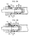
- FIGS. 3A and 3B are partially enlarged cross-sectional views of an arm cylinder
- FIG. 4 is a graph schematically illustrating the control of a controller
- FIG. 5 is a flow chart illustrating the control of the controller
- FIG. 6 illustrates a start-angle map used in the process shown in FIG. 5 ;
- FIG. 7 illustrates a current map used in the process shown in FIG. 5 .
- FIG. 1 illustrates the entire structure of a crawler construction machine according to an embodiment of the present invention.
- FIG. 2 is a schematic diagram illustrating a control device of the crawler construction machine shown in FIG. 1 .
- a construction machine which is an exemplary operating machine, to which the present invention is applied is described with reference to the drawings.
- a construction machine 1 includes a traveling section 2 having crawlers 2 a , a rotatable section 3 mounted on the traveling section 2 , a working attachment 4 installed in the front of the rotatable section 3 so as to be movable up and down, and a control device 5 (see FIG. 2 ) that controls the driving of the working attachment 4 .
- the working attachment 4 includes a two-part boom 6 having a first boom 6 a and a second boom 6 b , and an arm 7 connected to an end of the second boom 6 b .
- a crusher 8 is attached to an end of the arm 7 .
- the first boom 6 a moves up or down by a first boom cylinder 9 being extended or contracted
- the second boom 6 b moves up or down by a second boom cylinder 10 being extended or contracted.
- the arm 7 seesaws up or down around a horizontal shaft J 1 by an arm cylinder (hydraulic cylinder) 11 being extended or contracted
- the crusher 8 rotates up or down by a crusher cylinder 12 being extended or contracted.
- a rotation-angle sensor (detecting means) 14 for detecting the rotation angle of the arm 7 around the horizontal shaft J 1 is disposed between the second boom 6 b and the arm 7 .
- the control device 5 includes the rotation-angle sensor 14 , a hydraulic circuit 15 having supply and discharge routes of working oil supplied to and discharged from the arm cylinder 11 , and a controller (flow-controlling means) 16 for adjusting the flow rate of the working oil supplied and discharged by this hydraulic circuit 15 .
- FIGS. 3A and 3B are partially enlarged cross-sectional views of the arm cylinder 11 .
- the arm cylinder 11 includes a cylinder body 17 and a piston 18 that slides inside the cylinder body 17 such that a rod 19 extends and contracts with respect to the cylinder body 17 .
- the cylinder body 17 includes a tubular member 20 that has a circular cross-section and covers that close both open ends of the tubular member 20 .
- a cover 21 adjacent to the rod 19 is shown, and a cover adjacent to the head is not shown. Only the cover 21 will be described hereafter.
- the cover 21 has a hole 21 a and a shoulder 21 b , and the hole 21 a is coaxial with the bore of the tubular member 20 via the shoulder 21 b .
- the cover 21 has a bypass route 21 c passing from the shoulder 21 b alongside the surface of the hole 21 a and a throttle valve 21 d for adjusting the cross section of the flow channel of the bypass route 21 c .
- the hole 21 a is connected to ports 21 e for supplying and discharging the working oil.
- the piston 18 includes a piston body 22 that slides along the inner surface of the tubular member 20 and cushion rings 23 that are attached to either end of the piston body 22 .
- the same reference numeral 23 is used for both cushion rings.
- the cushion ring 23 can be inserted into the hole 21 a.
- the arm cylinder 11 has a mechanical cushion mechanism formed of the cover 21 and the cushion ring 23 .
- the state of the piston 18 can be changed from that shown in FIG. 3A to that shown in FIG. 3B .
- the cushion ring 23 of the piston 18 is hermetically fitted into the hole 21 a .
- the area of the piston 18 adjacent to the stroke end is partitioned into a cushion chamber C 1 between the piston body 22 and the shoulder 21 b and a discharge chamber C 2 between the cushion ring 23 and the hole 21 a .
- the hydraulic circuit 15 includes a pair of pumps (supply sources) 25 A and 25 B that supply the working oil to the arm cylinder 11 via three-position switching valves (first flow-adjusting means) 24 A and 24 B, respectively, and a remote-control valve (operating means) 26 that supplies the working oil from a pilot pump (not shown) to the three-position switching valves 24 A and 24 B.
- the three-position switching valves 24 A and 24 B are generically referred to as three-position switching valves 24
- the pumps 25 A and 25 B are generically referred to as pumps 25 when it is not necessary to discriminate these components.
- the pumps 25 are of a variable displacement type, and each includes a flow-adjusting section (second flow-adjusting means) 27 that adjusts the discharge flow rate in accordance with commands from the below-mentioned controller 16 described below.
- the three-position switching valves 24 are switched between three positions (A, B, and C) as described below. Specifically, the three-position switching valves 24 are retained at neutral positions C when the working oil is not supplied to either pilot ports 24 a or pilot ports 24 b , are switched to positions A when the working oil is supplied to the pilot ports 24 a , and are switched to positions B when the working oil is supplied to the pilot ports 24 b.
- the working oil from the pumps 25 is collected in a first oil tank, and at the same time, discharge routes of the working oil from the arm cylinder 11 are cut off.
- the working oil from the pumps 25 is supplied to one of the ports 21 e of the arm cylinder 11 for extending the rod 19 , and at the same time, the working oil discharged from the arm cylinder 11 is collected in a second oil tank.
- the working oil from the pumps 25 is supplied to the other of the ports 21 e of the arm cylinder 11 for contracting the rod 19 , and at the same time, the working oil discharged from the arm cylinder 11 is collected in the second oil tank.
- strokes from the neutral positions C to the positions A or the positions B of the three-position switching valves 24 change depending on the level of the pilot pressure of the working oil to the pilot ports 24 a or 24 b .
- the supply rate of the working oil supplied to the arm cylinder 11 and the discharge rate of the working oil discharged from the arm cylinder 11 can be adjusted.
- Relief valves 28 for limiting the pressure of the working oil supplied to the arm cylinder 11 to a predetermined value are disposed between the pumps 25 and the three-position switching valves 24 .
- the remote-control valve 26 can output a contracting command for contracting the rod 19 of the arm cylinder 11 (for rotating the arm 7 upward; see FIG. 1 ) or an extending command for extending the rod 19 (for rotating the arm 7 downward; see FIG. 1 ) in response to operation of a lever.
- the remote-control valve 26 outputs the contracting command in response to tilting of a lever 26 a from a neutral position shown in FIG. 2 to the left, and outputs the extending command in response to tilting of the lever 26 a to the right.
- the pilot pressure of the working oil that is supplied from the pilot pump (not shown) to the pilot ports 24 a or 24 b of the three-position switching valves 24 is increased as the inclination of the lever 26 a from the neutral position is increased.
- the remote-control valve 26 is operatively associated with the below-mentioned controller 16 , and higher current is applied to the flow-adjusting sections 27 as the inclination of the lever 26 a from the neutral position is increased such that the discharge flow rate of the working oil discharged from the pumps 25 is increased.
- the working oil from the pilot pump is supplied to the pilot ports 24 b while the discharge flow rate of the working oil discharged from the pumps 25 is regulated on the basis of the inclination of the lever 26 a .
- the working oil is supplied to the pilot ports 24 a while the discharge flow rate of the working oil discharged from the pumps 25 is regulated on the basis of the inclination of the lever 26 a.
- a proportional solenoid valve (forced-operated means) 29 is disposed between the remote-control valve 26 and the pilot port 24 a of the three-position switching valve 24 B.
- the proportional solenoid valve 29 can change the downstream pressure of the working oil (the pilot pressure to the pilot port 24 a ) in accordance with the commands (supply current) from the below-described controller 16 . Therefore, the proportional solenoid valve 29 can adjust the pilot pressure to the pilot port 24 a of three-position switching valve 24 B more preferentially than the outputs from the remote-control valve 26 , and thus adjust the supply rate of the working oil supplied to arm cylinder 11 and the discharge rate of the working discharged from the arm cylinder 11 .
- the controller 16 is electrically connected to the rotation-angle sensor 14 , the flow-adjusting sections 27 , and the proportional solenoid valve 29 .
- the controller 16 decelerates the piston 19 that is heading toward the stroke end of the arm cylinder 11 by operating the flow-adjusting sections 27 and the proportional solenoid valve 29 on the basis of the rotational position of the arm 7 detected by the rotation-angle sensor 14 .
- the controller 16 reduces the slowing-down length D 1 by setting the deceleration-start position of the piston 18 adjacent to the stroke end when the piston 18 is heading toward the stroke end at a relatively low speed V 1 , whereas the controller 16 sets the slowing-down length D 2 to be longer than the slowing-down length D 1 when the piston 18 is heading toward the stroke end at a speed V 2 higher than the speed V 1 . That is, the deceleration-start position of the piston 18 can be set further from the stroke end as the moving speed becomes larger.
- the rotation-angle sensor 14 detects and retains a rotation angle ⁇ (n) of the arm 7 (Step S 1 ).
- the rotation angle ⁇ (n) is the angle between the arm 7 and the second boom 6 b of the two-part boom 6 (see FIG. 1 ).
- an angle difference ⁇ (n) is calculated by subtracting the rotation angle ⁇ (n ⁇ 1) that was previously measured from the rotation angle ⁇ (n) measured in Step S 1 (Step S 2 ), and it is determined whether the rotational angle of the arm 7 has been reduced, i.e., the rod 19 is extended, at this time on the basis of the angle difference ⁇ (n) (Step S 3 ).
- Step S 3 when it is determined that the rod 19 is not extended, i.e., the rod 19 is suspended or contracted (NO in Step S 3 ), the process returns to Step S 1 .
- Step S 4 it is determined whether the rotation angle ⁇ (n) is smaller than or equal to a predetermined judgment angle ⁇ judge (Step S 4 ).
- the judgment angle ⁇ judge is a rotational angle of the arm 7 that is set on the basis of the position at which the deceleration of the rod 19 should be started when the rod 19 is extending at an expected maximum speed Vmax.
- the judgment angle ⁇ judge is set depending on the maximum speed Vmax, but may be set to a larger value at which the rod 19 is further contracted.
- Step S 4 when it is determined that the rotation angle ⁇ (n) is larger than the judgment angle ⁇ judge (NO in Step S 4 ), the process returns to Step S 1 .
- the average speed of the arm 7 is calculated on the basis of the five previous angle differences ⁇ (n), . . . , and ⁇ (n ⁇ 5) (Step S 5 ).
- a deceleration-start angle ⁇ B is determined on the basis of the average moving speed calculated in Step S 5 and a start-angle map M 1 that is retained beforehand (Step S 6 ).
- the start-angle map M 1 is a map defined on the basis of the speed and the angle of the arm 7 .
- the start-angle map is a data group lying on a straight line connecting the expected maximum speed Vmax at the judgment angle ⁇ judge and a preset angle ⁇ A of the arm 7 at which the speed is 0.
- a current map M 2 for determining the supply current to the proportional solenoid valve 29 is formed on the basis of the deceleration-start angle ⁇ B.
- the current map M 2 is a map defined on the basis of the values of the deceleration-start angle ⁇ B and illustrating values of the supply current supplied to the proportional solenoid valve 29 depending on the rotational angle of the arm 7 . That is, the current map M 2 is a data group lying on a straight line connecting a current value iA that is preset as a value of a current supplied to the proportional solenoid valve 29 at the angle ⁇ A (see FIG. 6 ) and the deceleration-start angle ⁇ B determined in Step S 6 .
- the inclination of the current map M 2 becomes gentler as the deceleration-start angle ⁇ B determined in Step S 6 becomes larger (for example, ⁇ B 1 in FIG. 7 ), whereas the inclination of the current map M 2 becomes steeper as the deceleration-start angle ⁇ B becomes smaller (for example, ⁇ B 3 in FIG. 7 ).
- a supply current i(n) supplied to the proportional solenoid valve 29 is determined on the basis of this current map M 2 (Step S 7 ), and, subsequently, the maximum flow rate of the working oil supplied from the three-position switching valves 24 to the arm cylinder 11 is determined according to the supply current i(n). Furthermore, on the basis of this maximum flow rate, a supply current imax supplied to the flow-adjusting sections 27 of the pumps 25 is calculated (Step S 8 ).
- the pilot pressure applied to the three-position switching valve 24 B is reduced by supplying the supply current i(n) to the proportional solenoid valve 29 , and therefore, the flow rate of the working oil supplied from the three-position switching valve 24 B to the arm cylinder 11 is reduced.
- this causes a difference between the upstream pressure and the downstream pressure of the three-position switching valve 24 B, and may cause instability of the accuracy of the flow rate.
- the maximum flow rate of the working oil supplied to the arm cylinder 11 is determined on the basis of the supply current i(n), and the supply current imax supplied to the flow-adjusting sections 27 is calculated such that the pumps 25 discharge the working oil at a rate depending on the maximum flow rate.
- Step S 9 it is determined whether supply currents ip 1 and ip 2 supplied to the corresponding flow-adjusting sections 27 at this time are larger than the supply current imax calculated in Step S 8 (Step S 9 ).
- the supply currents supplied to the flow-adjusting sections 27 are set to the supply current imax (Step S 10 ).
- the supply currents ip 1 and ip 2 depending on the inclination of the lever 26 a of the remote-control valve 26 are supplied to the corresponding flow-adjusting sections 27 , but when the supply currents ip 1 and ip 2 are larger than the supply current imax, it is determined that excessive working oil is discharged from the pumps 25 against the flow adjustment at the three-position switching valves 24 . Thus, the excessive discharge of the working oil is omitted.
- Step S 11 After the determination of NO in Step S 9 , or after the supply currents ip 1 and ip 2 are set to the supply current imax, it is determined whether the rotation-angle sensor 14 or the proportional solenoid valve 29 is under an abnormal condition (Step S 11 ).
- a method for detecting an abnormal condition of the rotation-angle sensor 14 for example, detection results of the rotational angle of the arm 7 are output to the controller 16 at a predetermined voltage.
- the rotation-angle sensor 14 has an angle-voltage characteristic with a voltage output range from 0.5 to 4.5 V, an output of 0 V is determined as a ground fault, and an output of 5 V is determined as a short-circuit to the power supply. In this manner, an abnormal condition can be determined.
- a feedback resistance is provided for the controller 16 . When an output expected from the feedback resistance is not obtained from the proportional solenoid valve 29 , it can be determined that the proportional solenoid valve 29 is under an abnormal condition.
- Step S 11 When it is determined that the rotation-angle sensor 14 or the proportional solenoid valve 29 is under an abnormal condition (YES in Step S 11 ), the supply current ip 1 supplied to the flow-adjusting section 27 of the pump 25 A connected to the three-position switching valve 24 A, which is not controlled by the proportional solenoid valve 29 , is set to the minimum value (Step S 12 ).
- the arm cylinder 11 can be reliably decelerated even if the deceleration control of the arm cylinder 11 cannot be normally performed on the basis of the rotational angle of the arm 7 .
- Step S 11 When it is determined that the rotation-angle sensor 14 and the proportional solenoid valve 29 are not under an abnormal condition (NO in Step S 11 ), or after Step S 12 , the supply current i(n) is supplied to the proportional solenoid valve 29 , and at the same time, the supply currents ip 1 and ip 2 (both are imax when set in Step S 10 ) are supplied to the corresponding flow-adjusting sections 27 (Step S 13 ).
- Step S 13 When the supply current ip 1 is set to the minimum value in Step S 12 , this value is retained in Step S 13 .
- Step S 13 the deceleration process is started from the deceleration-start angle ⁇ B depending on the speed of the arm 7 while the arm 7 is moved from a position corresponding to the rotational angle smaller than or equal to the judgment angle ⁇ judge to the stroke end of the arm cylinder 11 .
- the deceleration-start position of the piston 18 can be set further from the stroke end as the moving speed becomes larger. Since the piston 18 that approaches the stroke end at a high speed is decelerated in good time, the force depending on the inertia of the piston 18 can be canceled before the stroke end, thereby preventing the internal pressure of the cylinder body 17 from excessively increasing.
- the piston 18 of the arm cylinder 11 can be decelerated by reducing the supply rate of the working oil supplied to the arm cylinder 11 and the discharge rate of the working oil discharged from the arm cylinder 11 using the three-position switching valves 24 .
- the discharge flow rate of the working oil discharged from the pumps 25 can be reduced during the deceleration control of the piston 18 in which the supply rate of the working oil supplied to the arm cylinder 11 is regulated by operating the flow-adjusting sections 27 such that the discharge flow rate of the working oil discharged from the pumps 25 is reduced in response to the supply rate of the working oil supplied to the arm cylinder 11 , the supply rate being adjusted by the three-position switching valves 24 , as in the control device 5 .
- the rates of upstream supply and downstream supply of the working oil having the three-position switching valve 24 B interposed therebetween can be balanced, and thus the deceleration control of the piston 18 can be improved.
- the common arm cylinder 11 can be driven by two pumps 25 such that a large driving force is applied to the arm cylinder 11 during normal operation.
- the piston 18 can be decelerated by reducing the supply rate of the working oil supplied to the arm cylinder 11 and the discharge rate of the working oil discharged from the arm cylinder 11 using the pump 25 B during the deceleration control of the piston 18 while the pump 25 A, one of the two pumps 25 , is continued to be driven in response to the operation of the remote-control valve 26 .
- the supply rate of the working oil supplied to the arm cylinder 11 and the discharge rate of the working oil discharged from the arm cylinder 11 are set to the minimum value by operating the three-position switching valve 24 B, which is not driven by the proportional solenoid valve 29 .
- the piston 18 can be decelerated by the other three-position switching valve 24 B even if it is determined that the three-position switching valve 24 A cannot be controlled normally. Thus, higher safety can be achieved.
- the arm cylinder 11 includes the mechanical cushioning means. Therefore, the piston 18 can be decelerated more reliably in addition to the deceleration control of the piston 18 by the controller 16 .
- the deceleration control of the piston 18 is performed during extension of the rod 19 .
- a similar control may be also performed during contraction of the rod 19 .
- the deceleration-start angle ⁇ B is determined on the basis of the start-angle map M 1 (see FIG. 6 ) in which the deceleration-start angle is linearly changed in terms of the rotational speed.
- ranges of the deceleration-start angle may be set in terms of predetermined ranges of the rotational speed in a phased manner, and the deceleration-start angle may be determined using the range of the rotational speed in which the detected rotational speed is included. For example, when three ranges of the rotational speed are set and the actual rotational speed is included in the fastest speed range, the deceleration-start angle may be set to ⁇ B 1 shown in FIG. 7 .
- the deceleration-start angle may be set to ⁇ B 2 shown in FIG. 7 .
- the deceleration-start angle may be set to ⁇ B 3 shown in FIG. 7 .
- the piston 18 is decelerated by reducing the supply rate of the working oil supplied to the arm cylinder 11 and the discharge rate of the working oil discharged from the arm cylinder 11 using the three-position switching valves 24 .
- the three-position switching valves 24 may be omitted, and the piston 18 may be decelerated by reducing the supply rate of the working oil supplied to the arm cylinder 11 using the flow-adjusting sections 27 .
Landscapes
- Engineering & Computer Science (AREA)
- General Engineering & Computer Science (AREA)
- Physics & Mathematics (AREA)
- Fluid Mechanics (AREA)
- Mechanical Engineering (AREA)
- Mining & Mineral Resources (AREA)
- Civil Engineering (AREA)
- Structural Engineering (AREA)
- Fluid-Pressure Circuits (AREA)
- Operation Control Of Excavators (AREA)
- Actuator (AREA)
Applications Claiming Priority (2)
| Application Number | Priority Date | Filing Date | Title |
|---|---|---|---|
| JP2005233106A JP4114684B2 (ja) | 2005-08-11 | 2005-08-11 | 油圧シリンダの制御装置及びこれを備えた作業機械 |
| JP2005-233106 | 2005-08-11 |
Publications (2)
| Publication Number | Publication Date |
|---|---|
| US20070033934A1 US20070033934A1 (en) | 2007-02-15 |
| US7849685B2 true US7849685B2 (en) | 2010-12-14 |
Family
ID=37450809
Family Applications (1)
| Application Number | Title | Priority Date | Filing Date |
|---|---|---|---|
| US11/460,877 Active 2027-10-12 US7849685B2 (en) | 2005-08-11 | 2006-07-28 | Control device for hydraulic cylinder and operating machine including control device |
Country Status (4)
| Country | Link |
|---|---|
| US (1) | US7849685B2 (de) |
| EP (1) | EP1752664B1 (de) |
| JP (1) | JP4114684B2 (de) |
| CN (1) | CN1916429B (de) |
Cited By (5)
| Publication number | Priority date | Publication date | Assignee | Title |
|---|---|---|---|---|
| US20190049001A1 (en) * | 2017-08-10 | 2019-02-14 | Honda Motor Co., Ltd. | Hydraulic control device |
| CN113195904A (zh) * | 2019-01-28 | 2021-07-30 | 神钢建机株式会社 | 工程机械中的液压缸的驱动装置 |
| US11401958B2 (en) | 2016-06-09 | 2022-08-02 | Husqvarna Ab | Arrangement and method for operating a hydraulic cylinder |
| US20250027518A1 (en) * | 2023-07-17 | 2025-01-23 | Airbus Operations Gmbh | Hydraulic actuator and method for operating |
| US12618420B2 (en) * | 2023-07-17 | 2026-05-05 | Airbus Operations Gmbh | Hydraulic actuator and method for operating |
Families Citing this family (21)
| Publication number | Priority date | Publication date | Assignee | Title |
|---|---|---|---|---|
| DE10256923B4 (de) * | 2002-12-05 | 2013-10-24 | Liebherr-France S.A. | Verfahren und Vorrichtung zur Bewegungsdämpfung von Hydraulikzylindern mobiler Arbeitsmaschinen |
| KR100974275B1 (ko) * | 2007-12-17 | 2010-08-06 | 볼보 컨스트럭션 이키프먼트 홀딩 스웨덴 에이비 | 소 선회식 굴삭기의 붐 충격 완화장치 및 그 제어방법 |
| WO2011006461A2 (de) | 2009-07-16 | 2011-01-20 | Tiefenbach Control Systems Gmbh | Hydraulische schaltung für den strebausbau |
| US8876218B2 (en) | 2009-07-16 | 2014-11-04 | Tiefenbach Control Systems Gmbh | Hydraulic circuit for longwall support |
| GB2472005A (en) * | 2009-07-20 | 2011-01-26 | Ultronics Ltd | Control arrangement for monitoring a hydraulic system and altering opening of spool valve in response to operating parameters |
| CN102061714B (zh) * | 2010-12-03 | 2012-10-17 | 三一重机有限公司 | 一种用于挖掘机动臂下降的控制方法 |
| CN102384119B (zh) * | 2011-08-31 | 2013-01-16 | 中联重科股份有限公司 | 电液比例阀调速控制方法、装置、系统以及工程机械设备 |
| CN105317667B (zh) * | 2014-07-24 | 2017-03-15 | 中联重科股份有限公司 | 泵送速度控制方法、控制装置、泵送系统及工程机械 |
| JP6492806B2 (ja) * | 2015-03-12 | 2019-04-03 | コベルコ建機株式会社 | 建設機械のシリンダ制御装置 |
| JP6697361B2 (ja) * | 2016-09-21 | 2020-05-20 | 川崎重工業株式会社 | 油圧ショベル駆動システム |
| KR102054666B1 (ko) * | 2017-04-06 | 2020-01-22 | 두산인프라코어 주식회사 | 건설 기계의 유량 제어 방법 및 이를 수행하기 위한 시스템 |
| JP6551490B2 (ja) * | 2017-11-02 | 2019-07-31 | ダイキン工業株式会社 | 油圧装置 |
| CN108915945A (zh) * | 2018-06-26 | 2018-11-30 | 深圳市名业精密机电设备有限公司 | 活塞缸通过无极或分段调速精确定位方法 |
| JP7623108B2 (ja) | 2019-06-20 | 2025-01-28 | ジョイ・グローバル・サーフェイス・マイニング・インコーポレーテッド | 自動ダンプ制御を備えた産業機械 |
| JP7405611B2 (ja) * | 2019-12-27 | 2023-12-26 | 株式会社小松製作所 | 作業機械の制御システム、作業機械、作業機械の制御方法、及び作業機械の制御装置 |
| IT202000025864A1 (it) | 2020-10-30 | 2022-04-30 | Cnh Ind Italia Spa | Procedimenti di controllo per azionare il movimento di un braccio o un attrezzo in una macchina operatrice, corrispondenti sistemi di controllo e macchine operatrici comprendenti tali sistemi di controllo |
| CN112797287B (zh) * | 2021-02-07 | 2024-12-24 | 国网浙江省电力有限公司营销服务中心 | 直流互感器校验举升装置 |
| JP2024126182A (ja) * | 2023-03-07 | 2024-09-20 | キャタピラー エス エー アール エル | 流体圧シリンダの駆動制御装置 |
| CN116534744B (zh) * | 2023-04-24 | 2025-07-29 | 中石化石油工程技术服务股份有限公司 | 油田用多功能作业车的安全保护装置 |
| CN116838582A (zh) * | 2023-06-12 | 2023-10-03 | 中联重科股份有限公司 | 用于泵送装置的控制方法、存储介质、处理器及控制系统 |
| JP2025132739A (ja) * | 2024-02-29 | 2025-09-10 | 株式会社三井E&S | ガス圧縮機 |
Citations (9)
| Publication number | Priority date | Publication date | Assignee | Title |
|---|---|---|---|---|
| US4399653A (en) * | 1980-03-14 | 1983-08-23 | Pylat Jr John A | Automatic adjusting deceleration control for a hydrostatically powered device |
| US4741159A (en) * | 1986-04-08 | 1988-05-03 | Vickers, Incorporated | Power transmission |
| JPH01139101A (ja) | 1987-11-26 | 1989-05-31 | Sasakura Eng Co Ltd | 晶析装置 |
| JPH04181003A (ja) | 1990-11-15 | 1992-06-29 | Komatsu Ltd | 油圧シリンダの駆動制御装置 |
| JPH0632702A (ja) | 1992-05-18 | 1994-02-08 | Katayama Chem Works Co Ltd | 工業用殺菌剤及び工業用殺菌方法 |
| US5953976A (en) * | 1997-04-10 | 1999-09-21 | Buemach Engineering International B.V. | Working cylinder with dampened ends |
| JP2004100759A (ja) | 2002-09-06 | 2004-04-02 | Komatsu Ltd | スイング式油圧ショベルのスイング制御装置 |
| JP2004293628A (ja) | 2003-03-26 | 2004-10-21 | Kayaba Ind Co Ltd | 液圧シリンダの制御装置 |
| CN1566717A (zh) | 2002-12-05 | 2005-01-19 | 利布赫尔-法国股份有限公司 | 衰减可移动工程机械的液压缸运动的方法和装置 |
Family Cites Families (3)
| Publication number | Priority date | Publication date | Assignee | Title |
|---|---|---|---|---|
| SE459878B (sv) * | 1985-01-07 | 1989-08-14 | Akermans Verkstad Ab | Foerfarande och anordning foer att reducera kolvhastigheten i speciellt en arbetsmaskins kolv- och cylinderaggregat |
| DE3708989C2 (de) * | 1987-03-19 | 1993-10-14 | Festo Kg | Steuervorrichtung für einen in einem doppeltwirkenden Zylinder verschiebbaren Kolben |
| JPH06241206A (ja) | 1993-02-19 | 1994-08-30 | Toyota Motor Corp | ピストン速度制御装置 |
-
2005
- 2005-08-11 JP JP2005233106A patent/JP4114684B2/ja not_active Expired - Lifetime
-
2006
- 2006-07-27 EP EP06117975.0A patent/EP1752664B1/de not_active Not-in-force
- 2006-07-28 US US11/460,877 patent/US7849685B2/en active Active
- 2006-08-11 CN CN200610159244XA patent/CN1916429B/zh active Active
Patent Citations (10)
| Publication number | Priority date | Publication date | Assignee | Title |
|---|---|---|---|---|
| US4399653A (en) * | 1980-03-14 | 1983-08-23 | Pylat Jr John A | Automatic adjusting deceleration control for a hydrostatically powered device |
| US4741159A (en) * | 1986-04-08 | 1988-05-03 | Vickers, Incorporated | Power transmission |
| JPH01139101A (ja) | 1987-11-26 | 1989-05-31 | Sasakura Eng Co Ltd | 晶析装置 |
| JPH04181003A (ja) | 1990-11-15 | 1992-06-29 | Komatsu Ltd | 油圧シリンダの駆動制御装置 |
| JPH0632702A (ja) | 1992-05-18 | 1994-02-08 | Katayama Chem Works Co Ltd | 工業用殺菌剤及び工業用殺菌方法 |
| US5953976A (en) * | 1997-04-10 | 1999-09-21 | Buemach Engineering International B.V. | Working cylinder with dampened ends |
| JP2004100759A (ja) | 2002-09-06 | 2004-04-02 | Komatsu Ltd | スイング式油圧ショベルのスイング制御装置 |
| CN1566717A (zh) | 2002-12-05 | 2005-01-19 | 利布赫尔-法国股份有限公司 | 衰减可移动工程机械的液压缸运动的方法和装置 |
| JP2004293628A (ja) | 2003-03-26 | 2004-10-21 | Kayaba Ind Co Ltd | 液圧シリンダの制御装置 |
| GB2413862A (en) | 2003-03-26 | 2005-11-09 | Kayaba Industry Co Ltd | Control device for hydraulic cylinder |
Cited By (10)
| Publication number | Priority date | Publication date | Assignee | Title |
|---|---|---|---|---|
| US11401958B2 (en) | 2016-06-09 | 2022-08-02 | Husqvarna Ab | Arrangement and method for operating a hydraulic cylinder |
| US20190049001A1 (en) * | 2017-08-10 | 2019-02-14 | Honda Motor Co., Ltd. | Hydraulic control device |
| US10816092B2 (en) * | 2017-08-10 | 2020-10-27 | Honda Motor Co., Ltd. | Hydraulic control device including first and second hydraulic sensors |
| CN113195904A (zh) * | 2019-01-28 | 2021-07-30 | 神钢建机株式会社 | 工程机械中的液压缸的驱动装置 |
| EP3885586A4 (de) * | 2019-01-28 | 2022-01-19 | Kobelco Construction Machinery Co., Ltd. | Antriebsvorrichtung für hydraulikzylinder in einer arbeitsmaschine |
| US20220120295A1 (en) * | 2019-01-28 | 2022-04-21 | Kobelco Construction Machinery Co., Ltd. | Drive device for hydraulic cylinder in work machine |
| US11725673B2 (en) * | 2019-01-28 | 2023-08-15 | Kobelco Construction Machinery Co., Ltd. | Drive device for hydraulic cylinder in work machine |
| CN113195904B (zh) * | 2019-01-28 | 2023-08-29 | 神钢建机株式会社 | 工程机械中的液压缸的驱动装置 |
| US20250027518A1 (en) * | 2023-07-17 | 2025-01-23 | Airbus Operations Gmbh | Hydraulic actuator and method for operating |
| US12618420B2 (en) * | 2023-07-17 | 2026-05-05 | Airbus Operations Gmbh | Hydraulic actuator and method for operating |
Also Published As
| Publication number | Publication date |
|---|---|
| CN1916429A (zh) | 2007-02-21 |
| EP1752664A2 (de) | 2007-02-14 |
| EP1752664B1 (de) | 2013-04-10 |
| JP4114684B2 (ja) | 2008-07-09 |
| JP2007046732A (ja) | 2007-02-22 |
| EP1752664A3 (de) | 2011-12-14 |
| US20070033934A1 (en) | 2007-02-15 |
| CN1916429B (zh) | 2011-12-07 |
Similar Documents
| Publication | Publication Date | Title |
|---|---|---|
| US7849685B2 (en) | Control device for hydraulic cylinder and operating machine including control device | |
| EP2128453B1 (de) | Hydraulischer steuerkreis für baumaschine | |
| KR102451430B1 (ko) | 건설 기계의 선회 구동 장치 | |
| EP3594507B1 (de) | Schaufel | |
| EP2354331B1 (de) | Hydraulikantriebsvorrichtung für eine hydraulische Baumaschine | |
| KR102107579B1 (ko) | 건설 기계의 유압 구동 장치 | |
| EP3660228B1 (de) | Bagger | |
| KR20120123109A (ko) | 유압 작업기 | |
| US20210123213A1 (en) | Hydraulic drive device for operating machine | |
| JP6789843B2 (ja) | 油圧機械の制御装置 | |
| KR20150022883A (ko) | 건설 기계의 붐 구동 장치 | |
| US11542963B2 (en) | Hydraulic drive device for traveling work machine | |
| JP2011196439A (ja) | 旋回作業車の油圧回路 | |
| JP6106063B2 (ja) | 油圧駆動システム | |
| CN107217694B (zh) | 挖土机 | |
| JP2008180203A (ja) | 制御装置 | |
| US10107310B2 (en) | Hydraulic drive system | |
| JP2021156082A (ja) | ショベル | |
| JP2021021199A (ja) | ショベル | |
| JP3634980B2 (ja) | 建設機械の制御装置 | |
| JP6964059B2 (ja) | 建設機械 | |
| JP7001572B2 (ja) | 建設機械 | |
| JP7800186B2 (ja) | 建設機械の制御装置およびこれを備えた建設機械 | |
| JP3612253B2 (ja) | 建設機械の制御装置及びその制御方法 | |
| JP2018048515A (ja) | 建設機械の油圧駆動装置 |
Legal Events
| Date | Code | Title | Description |
|---|---|---|---|
| AS | Assignment |
Owner name: KOBELCO CONSTRUCTION MACHINERY CO., LTD., JAPAN Free format text: ASSIGNMENT OF ASSIGNORS INTEREST;ASSIGNORS:YAMAZAKI, YOICHIRO;HATAOKA, NOBUYOSHI;TOGO, HIROSHI;REEL/FRAME:018356/0050 Effective date: 20060501 |
|
| STCF | Information on status: patent grant |
Free format text: PATENTED CASE |
|
| FEPP | Fee payment procedure |
Free format text: PAYOR NUMBER ASSIGNED (ORIGINAL EVENT CODE: ASPN); ENTITY STATUS OF PATENT OWNER: LARGE ENTITY |
|
| FPAY | Fee payment |
Year of fee payment: 4 |
|
| MAFP | Maintenance fee payment |
Free format text: PAYMENT OF MAINTENANCE FEE, 8TH YEAR, LARGE ENTITY (ORIGINAL EVENT CODE: M1552) Year of fee payment: 8 |
|
| MAFP | Maintenance fee payment |
Free format text: PAYMENT OF MAINTENANCE FEE, 12TH YEAR, LARGE ENTITY (ORIGINAL EVENT CODE: M1553); ENTITY STATUS OF PATENT OWNER: LARGE ENTITY Year of fee payment: 12 |