EP2128453B1 - Hydraulischer steuerkreis für baumaschine - Google Patents
Hydraulischer steuerkreis für baumaschine Download PDFInfo
- Publication number
- EP2128453B1 EP2128453B1 EP07790891.1A EP07790891A EP2128453B1 EP 2128453 B1 EP2128453 B1 EP 2128453B1 EP 07790891 A EP07790891 A EP 07790891A EP 2128453 B1 EP2128453 B1 EP 2128453B1
- Authority
- EP
- European Patent Office
- Prior art keywords
- rotation speed
- control valve
- recovery
- pilot
- hydraulic
- Prior art date
- Legal status (The legal status is an assumption and is not a legal conclusion. Google has not performed a legal analysis and makes no representation as to the accuracy of the status listed.)
- Not-in-force
Links
Images


Classifications
-
- E—FIXED CONSTRUCTIONS
- E02—HYDRAULIC ENGINEERING; FOUNDATIONS; SOIL SHIFTING
- E02F—DREDGING; SOIL-SHIFTING
- E02F9/00—Component parts of dredgers or soil-shifting machines, not restricted to one of the kinds covered by groups E02F3/00 - E02F7/00
- E02F9/20—Drives; Control devices
- E02F9/22—Hydraulic or pneumatic drives
- E02F9/2221—Control of flow rate; Load sensing arrangements
- E02F9/2225—Control of flow rate; Load sensing arrangements using pressure-compensating valves
- E02F9/2228—Control of flow rate; Load sensing arrangements using pressure-compensating valves including an electronic controller
-
- E—FIXED CONSTRUCTIONS
- E02—HYDRAULIC ENGINEERING; FOUNDATIONS; SOIL SHIFTING
- E02F—DREDGING; SOIL-SHIFTING
- E02F9/00—Component parts of dredgers or soil-shifting machines, not restricted to one of the kinds covered by groups E02F3/00 - E02F7/00
- E02F9/20—Drives; Control devices
- E02F9/22—Hydraulic or pneumatic drives
- E02F9/2217—Hydraulic or pneumatic drives with energy recovery arrangements, e.g. using accumulators, flywheels
-
- E—FIXED CONSTRUCTIONS
- E02—HYDRAULIC ENGINEERING; FOUNDATIONS; SOIL SHIFTING
- E02F—DREDGING; SOIL-SHIFTING
- E02F9/00—Component parts of dredgers or soil-shifting machines, not restricted to one of the kinds covered by groups E02F3/00 - E02F7/00
- E02F9/20—Drives; Control devices
- E02F9/22—Hydraulic or pneumatic drives
- E02F9/2278—Hydraulic circuits
- E02F9/2285—Pilot-operated systems
-
- E—FIXED CONSTRUCTIONS
- E02—HYDRAULIC ENGINEERING; FOUNDATIONS; SOIL SHIFTING
- E02F—DREDGING; SOIL-SHIFTING
- E02F9/00—Component parts of dredgers or soil-shifting machines, not restricted to one of the kinds covered by groups E02F3/00 - E02F7/00
- E02F9/20—Drives; Control devices
- E02F9/22—Hydraulic or pneumatic drives
- E02F9/2278—Hydraulic circuits
- E02F9/2292—Systems with two or more pumps
-
- E—FIXED CONSTRUCTIONS
- E02—HYDRAULIC ENGINEERING; FOUNDATIONS; SOIL SHIFTING
- E02F—DREDGING; SOIL-SHIFTING
- E02F9/00—Component parts of dredgers or soil-shifting machines, not restricted to one of the kinds covered by groups E02F3/00 - E02F7/00
- E02F9/20—Drives; Control devices
- E02F9/22—Hydraulic or pneumatic drives
- E02F9/2278—Hydraulic circuits
- E02F9/2296—Systems with a variable displacement pump
-
- F—MECHANICAL ENGINEERING; LIGHTING; HEATING; WEAPONS; BLASTING
- F15—FLUID-PRESSURE ACTUATORS; HYDRAULICS OR PNEUMATICS IN GENERAL
- F15B—SYSTEMS ACTING BY MEANS OF FLUIDS IN GENERAL; FLUID-PRESSURE ACTUATORS, e.g. SERVOMOTORS; DETAILS OF FLUID-PRESSURE SYSTEMS, NOT OTHERWISE PROVIDED FOR
- F15B21/00—Common features of fluid actuator systems; Fluid-pressure actuator systems or details thereof, not covered by any other group of this subclass
- F15B21/14—Energy-recuperation means
-
- F—MECHANICAL ENGINEERING; LIGHTING; HEATING; WEAPONS; BLASTING
- F15—FLUID-PRESSURE ACTUATORS; HYDRAULICS OR PNEUMATICS IN GENERAL
- F15B—SYSTEMS ACTING BY MEANS OF FLUIDS IN GENERAL; FLUID-PRESSURE ACTUATORS, e.g. SERVOMOTORS; DETAILS OF FLUID-PRESSURE SYSTEMS, NOT OTHERWISE PROVIDED FOR
- F15B2211/00—Circuits for servomotor systems
- F15B2211/20—Fluid pressure source, e.g. accumulator or variable axial piston pump
- F15B2211/205—Systems with pumps
- F15B2211/20576—Systems with pumps with multiple pumps
-
- F—MECHANICAL ENGINEERING; LIGHTING; HEATING; WEAPONS; BLASTING
- F15—FLUID-PRESSURE ACTUATORS; HYDRAULICS OR PNEUMATICS IN GENERAL
- F15B—SYSTEMS ACTING BY MEANS OF FLUIDS IN GENERAL; FLUID-PRESSURE ACTUATORS, e.g. SERVOMOTORS; DETAILS OF FLUID-PRESSURE SYSTEMS, NOT OTHERWISE PROVIDED FOR
- F15B2211/00—Circuits for servomotor systems
- F15B2211/30—Directional control
- F15B2211/31—Directional control characterised by the positions of the valve element
- F15B2211/3105—Neutral or centre positions
- F15B2211/3116—Neutral or centre positions the pump port being open in the centre position, e.g. so-called open centre
-
- F—MECHANICAL ENGINEERING; LIGHTING; HEATING; WEAPONS; BLASTING
- F15—FLUID-PRESSURE ACTUATORS; HYDRAULICS OR PNEUMATICS IN GENERAL
- F15B—SYSTEMS ACTING BY MEANS OF FLUIDS IN GENERAL; FLUID-PRESSURE ACTUATORS, e.g. SERVOMOTORS; DETAILS OF FLUID-PRESSURE SYSTEMS, NOT OTHERWISE PROVIDED FOR
- F15B2211/00—Circuits for servomotor systems
- F15B2211/30—Directional control
- F15B2211/31—Directional control characterised by the positions of the valve element
- F15B2211/3122—Special positions other than the pump port being connected to working ports or the working ports being connected to the return line
-
- F—MECHANICAL ENGINEERING; LIGHTING; HEATING; WEAPONS; BLASTING
- F15—FLUID-PRESSURE ACTUATORS; HYDRAULICS OR PNEUMATICS IN GENERAL
- F15B—SYSTEMS ACTING BY MEANS OF FLUIDS IN GENERAL; FLUID-PRESSURE ACTUATORS, e.g. SERVOMOTORS; DETAILS OF FLUID-PRESSURE SYSTEMS, NOT OTHERWISE PROVIDED FOR
- F15B2211/00—Circuits for servomotor systems
- F15B2211/30—Directional control
- F15B2211/32—Directional control characterised by the type of actuation
- F15B2211/329—Directional control characterised by the type of actuation actuated by fluid pressure
-
- F—MECHANICAL ENGINEERING; LIGHTING; HEATING; WEAPONS; BLASTING
- F15—FLUID-PRESSURE ACTUATORS; HYDRAULICS OR PNEUMATICS IN GENERAL
- F15B—SYSTEMS ACTING BY MEANS OF FLUIDS IN GENERAL; FLUID-PRESSURE ACTUATORS, e.g. SERVOMOTORS; DETAILS OF FLUID-PRESSURE SYSTEMS, NOT OTHERWISE PROVIDED FOR
- F15B2211/00—Circuits for servomotor systems
- F15B2211/60—Circuit components or control therefor
- F15B2211/63—Electronic controllers
- F15B2211/6303—Electronic controllers using input signals
- F15B2211/6306—Electronic controllers using input signals representing a pressure
- F15B2211/6316—Electronic controllers using input signals representing a pressure the pressure being a pilot pressure
-
- F—MECHANICAL ENGINEERING; LIGHTING; HEATING; WEAPONS; BLASTING
- F15—FLUID-PRESSURE ACTUATORS; HYDRAULICS OR PNEUMATICS IN GENERAL
- F15B—SYSTEMS ACTING BY MEANS OF FLUIDS IN GENERAL; FLUID-PRESSURE ACTUATORS, e.g. SERVOMOTORS; DETAILS OF FLUID-PRESSURE SYSTEMS, NOT OTHERWISE PROVIDED FOR
- F15B2211/00—Circuits for servomotor systems
- F15B2211/60—Circuit components or control therefor
- F15B2211/63—Electronic controllers
- F15B2211/6303—Electronic controllers using input signals
- F15B2211/633—Electronic controllers using input signals representing a state of the prime mover, e.g. torque or rotational speed
-
- F—MECHANICAL ENGINEERING; LIGHTING; HEATING; WEAPONS; BLASTING
- F15—FLUID-PRESSURE ACTUATORS; HYDRAULICS OR PNEUMATICS IN GENERAL
- F15B—SYSTEMS ACTING BY MEANS OF FLUIDS IN GENERAL; FLUID-PRESSURE ACTUATORS, e.g. SERVOMOTORS; DETAILS OF FLUID-PRESSURE SYSTEMS, NOT OTHERWISE PROVIDED FOR
- F15B2211/00—Circuits for servomotor systems
- F15B2211/60—Circuit components or control therefor
- F15B2211/635—Circuits providing pilot pressure to pilot pressure-controlled fluid circuit elements
- F15B2211/6355—Circuits providing pilot pressure to pilot pressure-controlled fluid circuit elements having valve means
-
- F—MECHANICAL ENGINEERING; LIGHTING; HEATING; WEAPONS; BLASTING
- F15—FLUID-PRESSURE ACTUATORS; HYDRAULICS OR PNEUMATICS IN GENERAL
- F15B—SYSTEMS ACTING BY MEANS OF FLUIDS IN GENERAL; FLUID-PRESSURE ACTUATORS, e.g. SERVOMOTORS; DETAILS OF FLUID-PRESSURE SYSTEMS, NOT OTHERWISE PROVIDED FOR
- F15B2211/00—Circuits for servomotor systems
- F15B2211/70—Output members, e.g. hydraulic motors or cylinders or control therefor
- F15B2211/705—Output members, e.g. hydraulic motors or cylinders or control therefor characterised by the type of output members or actuators
- F15B2211/7051—Linear output members
- F15B2211/7053—Double-acting output members
-
- F—MECHANICAL ENGINEERING; LIGHTING; HEATING; WEAPONS; BLASTING
- F15—FLUID-PRESSURE ACTUATORS; HYDRAULICS OR PNEUMATICS IN GENERAL
- F15B—SYSTEMS ACTING BY MEANS OF FLUIDS IN GENERAL; FLUID-PRESSURE ACTUATORS, e.g. SERVOMOTORS; DETAILS OF FLUID-PRESSURE SYSTEMS, NOT OTHERWISE PROVIDED FOR
- F15B2211/00—Circuits for servomotor systems
- F15B2211/70—Output members, e.g. hydraulic motors or cylinders or control therefor
- F15B2211/76—Control of force or torque of the output member
- F15B2211/761—Control of a negative load, i.e. of a load generating hydraulic energy
-
- F—MECHANICAL ENGINEERING; LIGHTING; HEATING; WEAPONS; BLASTING
- F15—FLUID-PRESSURE ACTUATORS; HYDRAULICS OR PNEUMATICS IN GENERAL
- F15B—SYSTEMS ACTING BY MEANS OF FLUIDS IN GENERAL; FLUID-PRESSURE ACTUATORS, e.g. SERVOMOTORS; DETAILS OF FLUID-PRESSURE SYSTEMS, NOT OTHERWISE PROVIDED FOR
- F15B2211/00—Circuits for servomotor systems
- F15B2211/80—Other types of control related to particular problems or conditions
- F15B2211/88—Control measures for saving energy
Definitions
- the present invention relates to a hydraulic control circuit for a construction machine with a hydraulic cylinder that raises and lowers heavy loads.
- a construction machine such as a hydraulic shovel provided with various hydraulic actuators such as a hydraulic cylinder that raises and lowers heavy loads; a control valve that controls an oil supply and discharge to/from the hydraulic actuators based on an operation of operating units; and a hydraulic pump as a hydraulic supply source.
- a hydraulic actuator is a boom cylinder for raising and lowering a boom of a hydraulic shovel
- the boom cylinder extends to raise the boom through an oil supply to a head-side oil chamber as a weight holding-side oil chamber and an oil discharge from a rod-side oil chamber as an anti-weight holding-side oil chamber.
- the boom cylinder also retracts to lower the boom through an oil supply to the rod-side oil chamber and an oil discharge from the head-side oil chamber.
- a weight that is applied to the boom acts as a force by which the boom cylinder retracts, with a resultant pressure in the head-side oil chamber higher than the rod-side oil chamber.
- a recovery oil passage in which discharged oil from the head-side oil chamber is supplied as recovery oil to the rod-side oil chamber when the boom is lowered.
- Such recovery oil and pressure oil that is supplied from the hydraulic pump are configured to be supplied to the rod-side oil chamber while pressure is higher in the head-side oil chamber than the rod-side oil chamber.
- A-09-132927 for example
- a switching controls a supply flow rate from the hydraulic pump to the rod-side oil chamber when the boom is lowered (see Japanese Published Unexamined Patent Application No. A-2005-256895 , for example).
- Recovery oil is supplied to the rod-side oil chamber from the head-side oil chamber while no pressure oil is supplied from the hydraulic pump in order to lower the boom in an air. Accordingly, a discharge flow rate of the hydraulic pump can be reduced.
- An engine of the hydraulic shovel and various other construction machines is controlled to correspond to a target rotation speed that is set by an engine rotation speed setting unit such as an accelerator dial.
- the hydraulic pump is driven by the engine as a power source and controlled in such a manner that a maximum flow rate varies according to the set target rotation speed. Accordingly, a pump flow rate is controlled to increase at a higher engine rotation speed and decrease at a lower engine rotation speed.
- An operator can increase an engine output power by setting a higher target rotation speed in order to perform a higher speed and/or higher load operation and reduce an engine output power by setting a lower target rotation speed in order to perform a lower speed and/or lower load operation. In doing so, the operator attempts to achieve higher fuel efficiency.
- a lowering speed of the boom does not reflect an increase or decrease in the pump flow rate that is associated with a level of the target rotation speed set by the engine rotation speed setting unit of the above-mentioned configuration. It is because the recovery oil is supplied to the rod-side oil chamber to which no pressure oil is supplied from the hydraulic pump when the boom is lowered in the air. Accordingly, a lowering speed of the boom cannot be changed even if the operator sets a target rotation speed based on a desired operation speed, type and so on by using the engine rotation speed setting unit, with resultant poor workability.
- the present invention intends to solve such a problem.
- the invention according to a first exemplary aspect provides a hydraulic control circuit for a construction machine that includes a hydraulic cylinder that extends and retracts to raise a vertically movable heavy load through an oil supply to a weight holding-side oil chamber and an oil discharge from an anti-weight holding-side oil chamber and lower the heavy load through an oil supply to the anti-weight holding-side oil chamber and an oil discharge from the weight holding-side oil chamber; a control valve that controls the oil supply and discharge to/from the weight holding-side and anti-weight holding-side oil chambers of the hydraulic cylinder under an operation of a hydraulic cylinder operating unit; a recovery oil passage that supplies the discharged oil from the weight holding-side oil chamber to the anti-weight holding-side oil chamber when the heavy load is lowered; a hydraulic pump that is driven by an engine power source, the hydraulic pump functioning as a hydraulic supply source for the hydraulic cylinder; and an engine rotation speed setting unit that sets a target rotation speed of the engine.
- a recovery control valve is disposed to the recovery oil passage, and an opening amount of the recovery control valve is adjusted under a control command from a controller.
- the controller performs an engine rotation speed reduction control that reduces an engine rotation speed to not more than a preset reduction control engine rotation speed when the heavy load is lowered; and a recovery amount adjustment control that adjusts an increase or decrease in an opening amount of the recovery control valve in accordance with a level of the target rotation speed set by the engine rotation speed setting unit.
- the invention according to a second exemplary aspect provides the hydraulic control circuit for the construction machine according to the first exemplary aspect, in which the opening amount of the recovery control valve is adjusted based on a pilot pressure that is output from an electromagnetic proportional pressure control valve that operates under a control signal from the controller.
- the electromagnetic proportional pressure control valve is disposed to a pilot oil passage that runs to the recovery control valve from a pilot valve that outputs a pilot pressure under the operation of the hydraulic cylinder operating unit.
- the first exemplary aspect contributes significantly with respect to fuel efficiency because the engine rotation speed is reduced to not more than the preset reduction control engine rotation speed when the heavy load is lowered.
- the amount of recovery oil which is supplied from the weight holding-side oil chamber to the anti-weight holding-side oil chamber via the recovery control valve when the heavy load is lowered, increases or decreases in accordance with a level of the set target rotation speed set by the engine rotation speed setting unit. Accordingly, a lowering speed of the heavy load can be changed in accordance with the set target rotation speed, with resultant superior workability.
- the second exemplary aspect contributes with respect to the control simplification because the opening amount of the recovery control valve increases or decreases in accordance with an operation amount of the hydraulic cylinder operating unit without an additional control in order to correspond to the operation amount of the hydraulic cylinder operating unit.
- Reference numeral 1 denotes a hydraulic shovel in FIG. 1 .
- the hydraulic shovel 1 includes a crawler-type lower traveling body 2; an upper rotating body 3 that is supported rotatably on the lower traveling body 2; and a front working part 4 that is fit to the upper rotating body 3.
- the front working part 4 includes a boom 5 that has a base end portion supported vertically movably on the upper rotating body 3; a stick 6 that is supported anteroposteriorly swingably on a leading end portion of the boom 5; and a bucket 7 that is attached to a leading end portion of the stick 6.
- reference numeral 1a denotes a cab in which an operator drives the hydraulic shovel (see FIG. 1 ).
- the boom cylinder 8 (corresponding to a hydraulic cylinder of the present invention) extends to raise the boom 5 through an oil supply to a head-side oil chamber 8a and an oil discharge from a rod-side oil chamber 8b.
- the boom cylinder 8 also retracts to lower the boom 5 through an oil supply to the rod-side oil chamber 8b and an oil discharge from the head-side oil chamber 8a.
- the head-side oil chamber 8a corresponds to a weight holding-side oil chamber of the present invention to hold a full weight of the front working part 4 as a heavy load.
- the rod-side oil chamber 8b corresponds to an anti-weight holding-side oil chamber of the present invention.
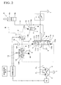
- the present invention is also applied to a hydraulic control circuit of the boom cylinder 8, which will be described below with reference to FIG. 2 .
- Reference symbol P denotes a capacity variable hydraulic pump that is driven by an engine E as a power source.
- Reference symbol T denotes an oil tank.
- Reference numeral 11 denotes a control valve that controls an oil supply and discharge to/from the boom cylinder 8.
- the control valve 11 includes raising-side and lowering-side pilot ports 11a and 11b.
- the control valve 11 is also configured to be a spool valve in which an opening amount of supply and discharge valve passages 11c to 11f, which will be described later, is adjusted based on pilot pressures that are input to the pilot ports 11a and 11b. More specifically, the control valve 11 is at a neutral position N so as not to supply or discharge oil to/from the boom cylinder 8 when no pilot pressure is input to the pilot ports 11a and 11b.
- Input of a pilot pressure to the raising-side pilot port 11 a causes the control valve 11 to move to a raising-side position X to open the supply valve passage 11c that supplies oil that is discharged from the hydraulic pumps P to the head-side oil chamber 8a of the boom cylinder 8.
- the control valve 11 Moving to the raising-side position X under the pilot pressure into the raising-side pilot port 11a, the control valve 11 also opens the discharge valve passage 11d that allows oil that is discharged from the rod-side oil chamber 8b to flow into the oil tank T.
- Input of a pilot pressure to the lowering-side pilot port 11b causes the control valve 11 to move to a lowering-side position Y to open the supply valve passage 11e that supplies oil that is discharged from the hydraulic pumps P to the rod-side oil chamber 8b through a throttle 11g.
- the control valve 11 Moving to the lowering-side position Y under the pressure into the lowering-side pilot port 11b, the control valve 11 also opens the discharge valve passage 11f to allow discharge oil from the head-side oil chamber 8a to flow into the oil tank T via a throttle 11h.
- a capacity varying means PL of the capacity variable hydraulic pumps P performs a negative flow rate control based on a flow rate through a center bypass valve passage 11i that is formed in the control valve 11; a constant horsepower control that controls a pump flow rate such that a horsepower is supplied constantly from the engine E; and a pump output increasing and decreasing control based on a control signal according to workload and engine rotation speed.
- the hydraulic pumps P are controlled such that a maximum pump flow rate is larger at a higher engine rotation speed and smaller at a lower engine rotation speed.
- Such flow rate controls are well known and, therefore, a detailed description thereof will be omitted.
- the hydraulic pumps P functions as a hydraulic supply source for not only the boom cylinder 8 but also the various hydraulic actuators such as the not shown rotating and left and right traveling motors, the boom cylinder 8, the stick cylinder 9 and the bucket cylinder 10.
- Control valves are disposed to discharge lines of the hydraulic pumps P in order to control an oil supply and discharge to/from the respective hydraulic actuators, though the control valves are also not shown in FIG. 2 .
- Reference symbol A denotes a boom head-side oil passage that connects the control valve 11 with the head-side oil chamber 8a of the boom cylinder 8.
- Reference symbol B denotes a boom rod-side oil passage that connects the control valve 11 with the rod-side oil chamber 8b of the boom cylinder 8.
- An oil supply and discharge is carried out between the control valve 11 and the boom cylinder 8 through the boom head-side and rod-side oil passages A and B, which communicate with each other via a recovery oil passage C.
- Reference numeral 13 denotes a recovery control valve that is disposed to the recovery oil passage C.
- the recovery control valve 13 is formed as a spool valve with a pilot port 13a.
- the control valve 13 stays in a closed position N to close the recovery oil passage C when no pilot pressure is input to the pilot port 13a.
- Input of pilot pressure to the pilot port 13a causes the recovery control valve 13 to switch to an open position X that opens the recovery oil passage C via a check valve 13b and a throttle 13c.
- an opening amount of the recovery control valve 13 is controlled to increase or decrease in accordance with a level of pilot pressure that is input to the pilot port 13a.
- the check valve 13b allows an oil flow from the boom head-side oil passage A to the boom rod-side oil passage B and prevents a reverse direction flow. Accordingly, when the recovery control valve 13 switches to the open position X so as to open the recovery oil passage C, oil that is discharged from the head-side oil chamber 8a can be supplied to the rod-side oil chamber 8b as recovery oil while a pressure in the head-side oil chamber 8a is higher than a pressure in the rod-side oil chamber 8b of the boom cylinder 8. In this state, a recovery amount from the head-side oil chamber 8a to the rod-side oil chamber 8b increases or decreases in accordance with a pressure difference between the head-side and rod-side oil chambers 8a and 8b as well as an opening amount of the recovery control valve 13.
- Reference numeral 14 denotes a pilot valve that outputs a pilot pressure based on an operation of a boom operation lever 15 (corresponding to a hydraulic cylinder operating unit of the present invention).
- the pilot valve 14 includes raising-side and lowering-side pilot valves 14X and 14Y.
- a pilot pressure is output from the raising-side pilot valve 14X to the raising-side pilot port 11a of the control valve 11.
- a pilot pressure is output from the lowering-side pilot valve 14Y to the lowering-side pilot port 11b of the control valve 11. In this state, a pilot pressure that is output from the pilot valve 14 is controlled to increase or decrease in accordance with an operation amount of the boom operation lever 15.
- Reference numeral 16 denotes a pilot hydraulic source to discharge a predetermined pressure (see FIG. 2 ).
- Reference symbol D denotes a lowering-side pilot oil passage that runs from the lowering-side pilot valve 14Y to the lowering-side pilot port 11b of the control valve 11.
- a lowering-side branch pilot oil passage F is formed to branch from the lowering-side pilot oil passage D and lead to the pilot port 13a of the recovery control valve 13.
- the lowering-side branch pilot oil passage F corresponds to a pilot oil passage that runs from the pilot valve to the recovery control valve of the present invention.
- Reference numeral 17 denotes an electromagnetic proportional pressure control valve that is disposed in the lowering-side branch pilot oil passage F. Based on a control signal from a controller 18, which will be described below, the electromagnetic proportional pressure control valve 17 reduces a pilot pressure that is output from the lowering-side pilot valve 14Y and outputs the pilot pressure to the pilot port 13a of the recovery control valve 13.
- the controller 18 includes a microcomputer and the like and receives input signals from a pressure switch 19 and an accelerator dial 20, which will be described later. Based on the input signals, the controller 18 outputs control commands to the electromagnetic proportional pressure control valve 17 and the engine E in order to perform an engine rotation speed reduction control and a recovery amount adjustment control, which are will be described later.
- the pressure switch 19 is connected to the lowering-side pilot oil passage D so as to determine whether the boom operation lever 15 is operated toward a lowering side.
- the pressure switch 19 turns on from off when a pilot pressure is output from the lowering-side pilot valve 14Y under an operation of the boom operation lever 15.
- the accelerator dial 20 (corresponding to an engine rotation speed setting unit of the present invention) is a setting unit that is mounted in the cab 1a where an operator can set a target rotation speed of the engine E with each dial number of the accelerator dial 20.
- a target rotation speed of the engine E to be set by the accelerator dial 20 will hereinafter be referred to as a set target rotation speed Ns.
- the engine rotation speed reduction control and the recovery amount adjustment control by the controller 18 will be described with reference to a flow chart in FIG. 3 .
- the controller 18 reads signals from the pressure switch 19 and the accelerator dial 20 (step S1).
- the controller 18 outputs a control command to the electromagnetic proportional pressure control valve 17 to reduce an output pilot pressure from the lowering-side pilot valve 14Y in accordance with a set target rotation speed Ns that is set by the accelerator dial 20 (step S2).
- step S2 the controller 18 outputs a control command to the electromagnetic proportional pressure control valve 17 to output the pilot pressure from the lowering-side pilot valve 14Y to the pilot port 13a of the recovery control valve 13 without reducing the pilot pressure when the set target rotation speed Ns is at a maximum (a dial number of the accelerator dial 20 is at a maximum).
- the controller 18 When the set target rotation speed Ns decreases, the controller 18 outputs a control command to the electromagnetic proportional pressure control valve 17 in order to reduce a ratio of a secondary pressure P2 (an pilot pressure that is output from the electromagnetic proportional pressure control valve 17 and input to the pilot port 13a of the recovery control valve 13) with respect to a primary pressure P1 (a pilot pressure that is output from the lowering-side pilot valve 14Y and input to the electromagnetic proportional pressure control valve 17). Accordingly, P2/P1 is reduced.
- the recovery amount adjustment control is carried out such that an opening amount of the recovery control valve 13 is adjusted to increase or decrease in accordance with a level of the set target rotation speed Ns by the accelerator dial 20.
- the recovery control valve 13 is controlled to reach a maximum opening amount when the set target rotation speed Ns is at a maximum or a smaller opening amount while the set target rotation speed Ns decreases.
- a recovery amount is set to be a value by which the boom can be lowered fast enough even if an engine rotation speed is reduced to a preset reduction control engine rotation speed Nd by an engine rotation speed reduction control, which will be described later.
- the opening amount of the recovery control valve 13 is adjusted to increase or decrease in accordance with an operation amount of the boom operation lever 15 because the pilot pressure output from the lowering-side pilot valve 14Y increases or decreases in accordance with the operation amount of the boom operation lever 15.
- step S3 the controller 18 determines based on an input signal from the pressure switch 19 whether there is an operation toward a boom lowering side. That is, the controller 18 determines that there is no operation toward a boom lowering side if the pressure switch 19 is off while the controller 18 determines that there is an operation toward a boom lowering side if the pressure switch 19 is on.
- step S3 determines based on an input signal from the accelerator dial 20 whether the set target rotation speed Ns by the accelerator dial 20 is greater than the reduction control engine rotation speed Nd (Ns > Nd?) in step S4. It returns to step S1 if it is determined "No” in step S3, that is, there is no operation toward a boom lowering side.
- the reduction control engine rotation speed Nd is a preset engine rotation speed in order to reduce an engine rotation speed amid a boom lowering, thereby achieving higher fuel efficiency.
- step S4 If it is determined “Yes” in step S4, that is, the target rotation speed Ns set by the accelerator dial 20 is greater than the reduction control engine rotation speed Nd (Ns > Nd), the controller 18 outputs a control command to the engine E such that the target rotation speed of the engine E corresponds to the reduction control engine rotation speed Nd (step S5).
- step S6 If it is determined "No” in step S4, that is, that the set target rotation speed Ns by the accelerator dial 20 is less or equal to the reduction control engine rotation speed Nd (Ns ⁇ Nd), the controller 18 outputs a control command to the engine E such that the target rotation speed of the engine E corresponds to the set target rotation speed Ns set by the accelerator dial 20 (step S6).
- the rotation speed of the engine E is controlled down to the reduction control engine rotation speed Nd through step S5 if the set target rotation speed Ns is higher than the reduction control engine rotation speed Nd.
- the rotation speed of the engine E is controlled to be the set target rotation speed Ns through step S6 if the set target rotation speed Ns is not more than the reduction control engine rotation speed Nd. This achieves the engine rotation speed reduction control in which the rotation speed of the engine E is reduced to not more than the reduction control engine rotation speed Nd.
- Step S 1 repeats after steps S5 or S6.
- a pilot pressure is output from the lowering-side pilot valve 14Y.
- the pilot pressure is then supplied to the lowering-side pilot port 11b of the control valve 11 through the lowering-side pilot oil passage D so as to cause the control valve 11 to switch to the lowering-side position Y.
- the pilot pressure is also supplied to the pilot port 13a of the recovery control valve 13 so as to cause the recovery control valve 13 to switch to the open position X, the pilot pressure having been through the electromagnetic proportional pressure control valve 17 of the lowering-side branch pilot oil passage F branching from the lowering-side pilot oil passage D.
- oil that is discharged from the head-side oil chamber 8a of the boom cylinder 8 is supplied as recovery oil to the rod-side oil chamber 8b through the recovery control valve 13 while surplus oil is discharged into the oil tank T through the control valve 11.
- Oil that is discharged from the hydraulic pumps P so as to be supplied through the control valve 11 flows into the recovery oil from the head-side oil chamber 8a so as to be supplied together to the rod-side oil chamber 8b.
- the engine E rotation speed is reduced to not more than the preset reduction control engine rotation speed Nd through the engine rotation speed reduction control and the recovery amount adjustment control by the controller 18.
- An opening amount of the recovery control valve 13 increases or decreases in accordance with a level of the target rotation speed Ns set by the accelerator dial 20.
- the engine rotation speed is reduced to not more than the reduction control engine rotation speed Nd when the boom 5 is lowered.
- This contributes greatly to fuel efficiency.
- the amount of the recovery oil from the head-side oil chamber 8a to the rod-side oil chamber 8b via the recovery control valve 13 increases or decreases in accordance with the level of the set target rotation speed Ns.
- the lowering speed of the boom varies in accordance with a level of the set target rotation speed Ns to be set arbitrarily by the operator using the accelerator dial 20, with resultant improved workability.
- the opening amount of the recovery control valve 13 when the set target rotation speed Ns is at maximum is set to be a sufficient recovery amount by which the boom can be lowered promptly even if the engine rotation speed is reduced to the reduction control engine rotation speed Nd.
- the opening amount of the recovery control valve 13 is adjusted based on a pilot pressure that is output from the electromagnetic proportional pressure control valve 17 that operates based on a control signal from the controller 18.
- the pilot pressure that is output from the electromagnetic proportional pressure control valve 17 to the recovery control valve 13 increases or decreases in accordance with an operation amount of the boom operation lever 15 without being controlled separately because the pilot pressure that is output from the lowering-side pilot valve 14Y serves as a primary pressure for the electromagnetic proportional pressure control valve 17.
- a simplified control is achieved.
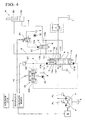
- FIGS. 4 and 5 Components in the second embodiment identical to those in the first embodiment are designated by the same reference numerals and symbols and a description thereof will be omitted.
- FIGS. 1 and 3 are shared with the first and second embodiments.
- an opening amount of a recovery control valve 13 disposed in a recovery oil passage C is adjusted to increase or decrease in accordance with a level of a pilot pressure that is input to a pilot port 13a.
- a pilot pressure from an electromagnetic proportional pressure control valve 21 is input to the pilot port 13a of the recovery control valve 13.
- the electromagnetic proportional pressure control valve 21 operates based on a control command from the controller 18.
- a primary side of the electromagnetic proportional pressure control valve 21 is connected to a pilot hydraulic source 16, according to the second embodiment.
- a pressure sensor 22 is connected to a lowering-side pilot oil passage D so as to detect a pilot pressure that is output from a lowering-side pilot valve 14Y.
- a controller 18 performs an engine rotation speed reduction control and recovery amount adjustment control in the second embodiment as well as the first embodiment.
- the controller 18 of the second embodiment includes a calculating means 23 that calculates the pilot pressure input from the electromagnetic proportional pressure control valve 21 to the recovery control valve 13 based on an operation amount of a boom operation lever 15 and a target rotation speed Ns to be set.
- the controller 18 outputs a control command to the electromagnetic proportional pressure control valve 21 based on a calculation result of the calculating means 23.
- a determination of whether there is an operation toward a boom lowering side is made based on an input signal from the pressure sensor 22 determining whether a pilot pressure that is output from the lowering-side pilot valve 14Y is not less than a preset pressure such as a minimum pressure required to move a spool of a control valve 11.
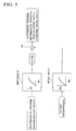
- the calculating means 23 first inputs to a first table 24 a pilot pressure P1 that is detected by the pressure sensor 22 (a pilot pressure that is output from the lowering-side pilot valve 14Y).
- the calculating means 23 also inputs to a second table 25 a target rotation speed Ns that is set by an accelerator dial 20.
- the first table 24 shows a relationship between the pilot pressure P1 output from the lowering-side pilot valve 14Y and an operation amount L of the boom operation lever 15. Based on the first table 24, the operation amount L of the boom operation lever 15 is obtained in a percentage (%) of its full operation.
- the second table 25 shows that a pilot pressure output from the electromagnetic proportional pressure control valve 21 to the recovery control valve 13 when the boom operation lever 15 is in full operation is set preliminarily in accordance with the set target rotation speed Ns.
- a full-operation pilot pressure Pm can be obtained that is output from the electromagnetic proportional pressure control valve 21 in accordance with the set target rotation speed Ns.
- the full-operation pilot pressure Pm is highest when a target rotation speed Ns is set at a maximum and decreases while the set target rotation speed Ns reduces.
- the calculating means 23 subsequently multiplies a hundredth part of the operation amount L (%) of the boom operation lever 15 obtained in the first table 24 by the full-operation pilot pressure Pm obtained in the second table 25 so as to calculate a pilot pressure that is output from the electromagnetic proportional pressure control valve 21 to the recovery control valve 13.
- the pilot pressure output from the electromagnetic proportional pressure control valve 21 to the recovery control valve 13 can be controlled to increase or decrease in accordance with an operation amount of the boom operation lever 15 and a target rotation speed Ns set by the accelerator dial 20.
- the opening amount of the recovery control valve 13 is controlled to increase or decrease in accordance with the operation amount of the boom operation lever 15 and a level of the set target rotation speed Ns even if the electromagnetic proportional pressure control valve 21 is used where the primary side is connected to the pilot hydraulic source 16.
- the second embodiment can achieve similar advantages of the first embodiment.
- the present invention is not restricted to the first and second embodiments. Values detected by the pressure switch or the pressure sensor are used to determine if there is an operation toward a boom lowering side and/or calculate an operation amount of the boom operation lever according to the first and second embodiments.
- an operation detecting means may be provided so as to electrically detect a direction and/or amount of operation of the boom operation lever, for example. Accordingly, based on detection signals from the operation detecting means, the above-mentioned determination and/or calculation of the first and second embodiments may be carried out.
- an opening amount of the recovery control valve is adjusted based on a pilot pressure output from the electromagnetic proportional pressure control valve based on a control command from the controller according to the first and second embodiments.
- the recovery control valve in itself may be formed to be an electromagnetic proportional flow rate control valve in which an opening amount thereof is adjusted based on a control command from the controller.
- the negative flow rate control is employed so as to control a flow rate of the hydraulic pumps under an operation amount of operating units according to the first and second embodiments.
- the present invention can also be carried out by applying a positive flow rate control or a load-sensing flow rate control.
- the engine rotation speed reduction control and the recovery amount adjustment control of the present invention may be combined with a pump flow rate reduction control in which a discharge flow rate of hydraulic pumps is configured to reduce when a heavy load is lowered.
- the engine rotation speed reduction control may be deactivated amid interlocking operations in which other hydraulic actuators are operated that use hydraulic pumps as a hydraulic supply source at a time of lowering a heavy load.
- the present invention is, of course, applicable to not only the hydraulic control circuit of the boom cylinder in the hydraulic shovel but also hydraulic control circuits for various construction machines with hydraulic cylinders for raising and lowering heavy loads.
- the present invention is useful in a hydraulic control circuit for a construction machine with a hydraulic cylinder for raising and lowering a heavy load.
- a lowering speed of a heavy load can be not only changed in accordance with a set target engine rotation speed, with resultant superior workability, but also increased or decreased in accordance with an operation amount of a hydraulic cylinder operating unit, with a resultant simplified control.
Claims (2)
- Hydrauliksteuerkreis für eine Baumaschine, der Folgendes umfasst:- einen Hydraulikzylinder (8), der ausfährt und zurückfährt, um eine vertikal bewegliche schwere Last durch eine Ölzufuhr zu einer Ölkammer (8a) auf der Gewichtshalteseite und einen Ölablass aus einer Ölkammer (8b) auf der Gegengewichtshalteseite anzuheben und die schwere Last durch eine Ölzufuhr zu der Ölkammer (8b) auf der Gegengewichtshalteseite und einen Ölablass aus der Ölkammer (8a) auf der Gewichtshalteseite abzusenken;- ein Steuerventil (11), das die Ölzufuhr und den Ölablass zu bzw. aus der Ölkammer (8a, 8b) auf der Gewichtshalteseite und auf der Gegengewichtshalteseite des Hydraulikzylinders (8) unter dem Einfluss einer Einheit zum Betätigen des Hydraulikzylinders (15) steuert;- einen Durchgang zur Ölrückgewinnung (C), der das abgelassene Öl aus der Ölkammer (8a) auf der Gewichtshalteseite zu der Ölkammer (8b) auf der Gegengewichtshalteseite führt, wenn die schwere Last abgesenkt wird;- eine Hydraulikpumpe (P), die durch eine motorische Kraftquelle (E) angetrieben wird, wobei die Hydraulikpumpe (P) als eine Hydraulikkraftquelle für den Hydraulikzylinder (8) fungiert;- eine Einheit zum Einstellen der Motordrehzahl (20), die eine Solldrehzahl des Motors (E) einstellt; dadurch gekennzeichnet, dass der Hydrauliksteuerkreis des Weiteren Folgendes umfasst:- ein Ventil zum Steuern der Rückgewinnung (13), das in dem Durchgang zur Ölrückgewinnung (C) angeordnet ist und das Volumen des Rückgewinnungsöls durch Steuern der Öffnung des Ventils zum Steuern der Rückgewinnung steuert, und- eine Steuereinheit (18), welche die Drehzahl des Motors (E) steuert und die Öffnung des Ventils zum Steuern der Rückgewinnung (13) steuert, wobeidie Steuereinheit (18) Folgendes ausführt, wenn die schwere Last abgesenkt wird:ein Steuern zum Verringern der Motordrehzahl, die eine Motordrehzahl auf eine voreingestellte Verringerungssteuerungs-Motordrehzahl (Nd) senkt, wenn eine voreingestellte Solldrehzahl (Ns), die durch die Einheit zum Einstellen der Motordrehzahl (20) voreingestellt wurde, höher ist als die voreingestellte Verringerungssteuerungs-Motordrehzahl (Nd); undein Steuern zum Justieren des Rückgewinnungsvolumens, die eine Vergrößerung oder Verkleinerung der Öffnung des Ventils zum Steuern der Rückgewinnung (13) gemäß einer Höhe der Solldrehzahl, die durch die Einheit zum Einstellen der Motordrehzahl (20) eingestellt wurde, justiert.
- Hydrauliksteuerkreis nach Anspruch 1, wobei die Öffnung des Ventils zum Steuern der Rückgewinnung auf der Grundlage eines Vorsteuerdrucks justiert wird, der von einem elektromagnetischen Ventil zum Steuern des Proportionaldrucks ausgegeben wird, der unter dem Einfluss eines Steuersignals von der Steuereinheit arbeitet, wobei das elektromagnetische Ventil zum Steuern des Proportionaldrucks in einem Vorsteuer-Öldurchgang angeordnet ist, der vom einem Vorsteuerventil, das einen Vorsteuerdruck unter dem Einfluss der Einheit zum Betätigen des Hydraulikzylinders ausgibt, zu dem Ventil zum Steuern der Rückgewinnung verläuft.
Applications Claiming Priority (2)
| Application Number | Priority Date | Filing Date | Title |
|---|---|---|---|
| JP2007055319A JP5013452B2 (ja) | 2007-03-06 | 2007-03-06 | 建設機械における油圧制御回路 |
| PCT/JP2007/064136 WO2008108013A1 (ja) | 2007-03-06 | 2007-07-18 | 建設機械における油圧制御回路 |
Publications (3)
| Publication Number | Publication Date |
|---|---|
| EP2128453A1 EP2128453A1 (de) | 2009-12-02 |
| EP2128453A4 EP2128453A4 (de) | 2011-10-05 |
| EP2128453B1 true EP2128453B1 (de) | 2013-06-05 |
Family
ID=39737915
Family Applications (1)
| Application Number | Title | Priority Date | Filing Date |
|---|---|---|---|
| EP07790891.1A Not-in-force EP2128453B1 (de) | 2007-03-06 | 2007-07-18 | Hydraulischer steuerkreis für baumaschine |
Country Status (5)
| Country | Link |
|---|---|
| US (1) | US8539762B2 (de) |
| EP (1) | EP2128453B1 (de) |
| JP (1) | JP5013452B2 (de) |
| CN (1) | CN101595313B (de) |
| WO (1) | WO2008108013A1 (de) |
Families Citing this family (17)
| Publication number | Priority date | Publication date | Assignee | Title |
|---|---|---|---|---|
| JP2010210072A (ja) * | 2009-03-12 | 2010-09-24 | Sumitomo (Shi) Construction Machinery Co Ltd | 作業機械の油圧制御システム |
| JP5461234B2 (ja) * | 2010-02-26 | 2014-04-02 | カヤバ工業株式会社 | 建設機械の制御装置 |
| JP2012052583A (ja) * | 2010-08-31 | 2012-03-15 | Hitachi Constr Mach Co Ltd | 油圧作業機 |
| US20140137549A1 (en) * | 2011-07-26 | 2014-05-22 | Volvo Construction Equipment Ab | Hydraulic system for construction machinery |
| DE102012001562A1 (de) * | 2012-01-27 | 2013-08-01 | Robert Bosch Gmbh | Ventilanordnung für eine mobile Arbeitsmaschine |
| KR101990177B1 (ko) * | 2013-01-17 | 2019-06-17 | 히다찌 겐끼 가부시키가이샤 | 작업 기계의 압유 에너지 회수 장치 |
| EP3006745B1 (de) * | 2013-05-24 | 2018-10-24 | Hitachi Construction Machinery Co., Ltd. | Baumaschine |
| CN103758175A (zh) * | 2013-12-28 | 2014-04-30 | 柳州市金福机械制造有限公司 | 滑移式装载机变速控制装置 |
| CN103883409B (zh) * | 2014-03-14 | 2017-02-15 | 潍柴动力股份有限公司 | 一种双执行器切换控制方法及装置 |
| JP6285787B2 (ja) * | 2014-04-14 | 2018-02-28 | 日立建機株式会社 | 油圧駆動装置 |
| CN104405707B (zh) * | 2014-10-21 | 2016-06-01 | 恒天创丰重工有限公司 | 一种多泵液压系统及其功率控制方法 |
| JP2017015118A (ja) * | 2015-06-29 | 2017-01-19 | Kyb株式会社 | 建設機械の制御システム |
| JP2018044366A (ja) * | 2016-09-15 | 2018-03-22 | コベルコ建機株式会社 | 作業機械の挟み処理装置及びこれを備えた作業機械 |
| JP6646007B2 (ja) * | 2017-03-31 | 2020-02-14 | 日立建機株式会社 | 建設機械の油圧制御装置 |
| JP6467733B1 (ja) | 2018-05-21 | 2019-02-13 | Smc株式会社 | 流体圧シリンダの駆動方法及び駆動装置 |
| JP7269436B2 (ja) * | 2020-03-30 | 2023-05-08 | 日立建機株式会社 | 作業機械 |
| JP2022001769A (ja) * | 2020-06-19 | 2022-01-06 | 川崎重工業株式会社 | 液圧駆動システム |
Family Cites Families (10)
| Publication number | Priority date | Publication date | Assignee | Title |
|---|---|---|---|---|
| KR950700493A (ko) * | 1992-12-04 | 1995-01-16 | 오까다 하지메 | 유압재생장치 |
| JP2992434B2 (ja) * | 1993-12-02 | 1999-12-20 | 日立建機株式会社 | 建設機械の油圧制御装置 |
| JPH09132927A (ja) | 1995-11-08 | 1997-05-20 | Komatsu Ltd | 油圧ショベルの油圧回路 |
| JP2000110803A (ja) * | 1998-10-05 | 2000-04-18 | Hitachi Constr Mach Co Ltd | 油圧再生装置 |
| JP3797665B2 (ja) * | 2002-08-19 | 2006-07-19 | 住友建機製造株式会社 | 建設機械の省エネ回路 |
| JP4017073B2 (ja) * | 2002-10-29 | 2007-12-05 | 株式会社小松製作所 | 作業機械のエンジン回転数制御装置 |
| JP2005256895A (ja) | 2004-03-10 | 2005-09-22 | Hitachi Constr Mach Co Ltd | 作業用油圧シリンダの駆動制御装置および油圧ショベル |
| JP2006070970A (ja) * | 2004-09-01 | 2006-03-16 | Shin Caterpillar Mitsubishi Ltd | 建設機械の油圧制御回路 |
| JP2006118685A (ja) * | 2004-10-25 | 2006-05-11 | Shin Caterpillar Mitsubishi Ltd | 作業機械の流体圧回路 |
| EP1898104A4 (de) * | 2005-06-06 | 2009-05-06 | Caterpillar Japan Ltd | Fluiddruckkreislauf, energierückgewinnungsvorrichtung und fluiddruckrückgewinnungskreislauf für arbeitsmaschine |
-
2007
- 2007-03-06 JP JP2007055319A patent/JP5013452B2/ja not_active Expired - Fee Related
- 2007-07-18 CN CN2007800506473A patent/CN101595313B/zh not_active Expired - Fee Related
- 2007-07-18 US US12/449,824 patent/US8539762B2/en not_active Expired - Fee Related
- 2007-07-18 WO PCT/JP2007/064136 patent/WO2008108013A1/ja active Application Filing
- 2007-07-18 EP EP07790891.1A patent/EP2128453B1/de not_active Not-in-force
Also Published As
| Publication number | Publication date |
|---|---|
| US20100089045A1 (en) | 2010-04-15 |
| EP2128453A1 (de) | 2009-12-02 |
| CN101595313A (zh) | 2009-12-02 |
| JP2008215528A (ja) | 2008-09-18 |
| JP5013452B2 (ja) | 2012-08-29 |
| CN101595313B (zh) | 2012-05-23 |
| EP2128453A4 (de) | 2011-10-05 |
| WO2008108013A1 (ja) | 2008-09-12 |
| US8539762B2 (en) | 2013-09-24 |
Similar Documents
| Publication | Publication Date | Title |
|---|---|---|
| EP2128453B1 (de) | Hydraulischer steuerkreis für baumaschine | |
| US7059125B2 (en) | Hydraulic controller for construction machine | |
| KR100807923B1 (ko) | 작업용 차량의 속도제어장치 및 그의 속도제어방법 | |
| US9181684B2 (en) | Pump control unit for hydraulic system | |
| KR100824662B1 (ko) | 작업기계의 유압구동장치 | |
| US10526767B2 (en) | Construction machine | |
| EP2320093B1 (de) | Vorrichtung zur unterdrückung eines vorübergehenden motordrehzahlabfalls für hydraulik-arbeitsmaschinen | |
| EP2354331B1 (de) | Hydraulikantriebsvorrichtung für eine hydraulische Baumaschine | |
| EP3505688B1 (de) | System zur steuerung einer baumaschine und verfahren zur steuerung einer baumaschine | |
| JP2010101365A (ja) | 作業機械における油圧制御システム | |
| US11542963B2 (en) | Hydraulic drive device for traveling work machine | |
| CN112105785A (zh) | 工程机械的液压驱动装置 | |
| US11060261B2 (en) | Slewing hydraulic work machine | |
| JP4232974B2 (ja) | 建設機械の油圧制御回路 | |
| JP2004197825A (ja) | 液圧駆動装置 | |
| CN108884843B (zh) | 挖土机及挖土机用控制阀门 | |
| JP2003090302A (ja) | 建設機械の油圧制御回路 | |
| JP2008185098A (ja) | 作業機械における制御システム | |
| CN113474519B (zh) | 工作机器的液压控制回路 | |
| CN111356844B (zh) | 油压驱动系统 | |
| CN115038844A (zh) | 液压系统 | |
| US20140331660A1 (en) | Hydraulic Machinery | |
| JP2008185099A (ja) | 作業機械における制御システム | |
| JP4953378B2 (ja) | 建設機械における油圧制御システム | |
| JPS63219735A (ja) | 土木建設機械の油圧駆動装置 |
Legal Events
| Date | Code | Title | Description |
|---|---|---|---|
| PUAI | Public reference made under article 153(3) epc to a published international application that has entered the european phase |
Free format text: ORIGINAL CODE: 0009012 |
|
| 17P | Request for examination filed |
Effective date: 20090922 |
|
| AK | Designated contracting states |
Kind code of ref document: A1 Designated state(s): AT BE BG CH CY CZ DE DK EE ES FI FR GB GR HU IE IS IT LI LT LU LV MC MT NL PL PT RO SE SI SK TR |
|
| DAX | Request for extension of the european patent (deleted) | ||
| RAP1 | Party data changed (applicant data changed or rights of an application transferred) |
Owner name: CATERPILLAR SARL |
|
| A4 | Supplementary search report drawn up and despatched |
Effective date: 20110905 |
|
| RIC1 | Information provided on ipc code assigned before grant |
Ipc: E02F 9/22 20060101ALI20110830BHEP Ipc: F15B 11/024 20060101AFI20110830BHEP |
|
| 17Q | First examination report despatched |
Effective date: 20120918 |
|
| GRAP | Despatch of communication of intention to grant a patent |
Free format text: ORIGINAL CODE: EPIDOSNIGR1 |
|
| GRAS | Grant fee paid |
Free format text: ORIGINAL CODE: EPIDOSNIGR3 |
|
| GRAA | (expected) grant |
Free format text: ORIGINAL CODE: 0009210 |
|
| AK | Designated contracting states |
Kind code of ref document: B1 Designated state(s): AT BE BG CH CY CZ DE DK EE ES FI FR GB GR HU IE IS IT LI LT LU LV MC MT NL PL PT RO SE SI SK TR |
|
| REG | Reference to a national code |
Ref country code: GB Ref legal event code: FG4D |
|
| REG | Reference to a national code |
Ref country code: CH Ref legal event code: EP |
|
| REG | Reference to a national code |
Ref country code: AT Ref legal event code: REF Ref document number: 615823 Country of ref document: AT Kind code of ref document: T Effective date: 20130615 |
|
| REG | Reference to a national code |
Ref country code: IE Ref legal event code: FG4D |
|
| REG | Reference to a national code |
Ref country code: DE Ref legal event code: R096 Ref document number: 602007030910 Country of ref document: DE Effective date: 20130801 |
|
| REG | Reference to a national code |
Ref country code: AT Ref legal event code: MK05 Ref document number: 615823 Country of ref document: AT Kind code of ref document: T Effective date: 20130605 |
|
| PG25 | Lapsed in a contracting state [announced via postgrant information from national office to epo] |
Ref country code: AT Free format text: LAPSE BECAUSE OF FAILURE TO SUBMIT A TRANSLATION OF THE DESCRIPTION OR TO PAY THE FEE WITHIN THE PRESCRIBED TIME-LIMIT Effective date: 20130605 Ref country code: ES Free format text: LAPSE BECAUSE OF FAILURE TO SUBMIT A TRANSLATION OF THE DESCRIPTION OR TO PAY THE FEE WITHIN THE PRESCRIBED TIME-LIMIT Effective date: 20130916 Ref country code: SI Free format text: LAPSE BECAUSE OF FAILURE TO SUBMIT A TRANSLATION OF THE DESCRIPTION OR TO PAY THE FEE WITHIN THE PRESCRIBED TIME-LIMIT Effective date: 20130605 Ref country code: FI Free format text: LAPSE BECAUSE OF FAILURE TO SUBMIT A TRANSLATION OF THE DESCRIPTION OR TO PAY THE FEE WITHIN THE PRESCRIBED TIME-LIMIT Effective date: 20130605 Ref country code: LT Free format text: LAPSE BECAUSE OF FAILURE TO SUBMIT A TRANSLATION OF THE DESCRIPTION OR TO PAY THE FEE WITHIN THE PRESCRIBED TIME-LIMIT Effective date: 20130605 Ref country code: GR Free format text: LAPSE BECAUSE OF FAILURE TO SUBMIT A TRANSLATION OF THE DESCRIPTION OR TO PAY THE FEE WITHIN THE PRESCRIBED TIME-LIMIT Effective date: 20130906 Ref country code: SE Free format text: LAPSE BECAUSE OF FAILURE TO SUBMIT A TRANSLATION OF THE DESCRIPTION OR TO PAY THE FEE WITHIN THE PRESCRIBED TIME-LIMIT Effective date: 20130605 |
|
| REG | Reference to a national code |
Ref country code: NL Ref legal event code: VDEP Effective date: 20130605 |
|
| REG | Reference to a national code |
Ref country code: LT Ref legal event code: MG4D |
|
| PG25 | Lapsed in a contracting state [announced via postgrant information from national office to epo] |
Ref country code: PL Free format text: LAPSE BECAUSE OF FAILURE TO SUBMIT A TRANSLATION OF THE DESCRIPTION OR TO PAY THE FEE WITHIN THE PRESCRIBED TIME-LIMIT Effective date: 20130605 Ref country code: BG Free format text: LAPSE BECAUSE OF FAILURE TO SUBMIT A TRANSLATION OF THE DESCRIPTION OR TO PAY THE FEE WITHIN THE PRESCRIBED TIME-LIMIT Effective date: 20130905 |
|
| PG25 | Lapsed in a contracting state [announced via postgrant information from national office to epo] |
Ref country code: LV Free format text: LAPSE BECAUSE OF FAILURE TO SUBMIT A TRANSLATION OF THE DESCRIPTION OR TO PAY THE FEE WITHIN THE PRESCRIBED TIME-LIMIT Effective date: 20130605 |
|
| PG25 | Lapsed in a contracting state [announced via postgrant information from national office to epo] |
Ref country code: SK Free format text: LAPSE BECAUSE OF FAILURE TO SUBMIT A TRANSLATION OF THE DESCRIPTION OR TO PAY THE FEE WITHIN THE PRESCRIBED TIME-LIMIT Effective date: 20130605 Ref country code: BE Free format text: LAPSE BECAUSE OF FAILURE TO SUBMIT A TRANSLATION OF THE DESCRIPTION OR TO PAY THE FEE WITHIN THE PRESCRIBED TIME-LIMIT Effective date: 20130605 Ref country code: CZ Free format text: LAPSE BECAUSE OF FAILURE TO SUBMIT A TRANSLATION OF THE DESCRIPTION OR TO PAY THE FEE WITHIN THE PRESCRIBED TIME-LIMIT Effective date: 20130605 Ref country code: IS Free format text: LAPSE BECAUSE OF FAILURE TO SUBMIT A TRANSLATION OF THE DESCRIPTION OR TO PAY THE FEE WITHIN THE PRESCRIBED TIME-LIMIT Effective date: 20131005 Ref country code: PT Free format text: LAPSE BECAUSE OF FAILURE TO SUBMIT A TRANSLATION OF THE DESCRIPTION OR TO PAY THE FEE WITHIN THE PRESCRIBED TIME-LIMIT Effective date: 20131007 Ref country code: EE Free format text: LAPSE BECAUSE OF FAILURE TO SUBMIT A TRANSLATION OF THE DESCRIPTION OR TO PAY THE FEE WITHIN THE PRESCRIBED TIME-LIMIT Effective date: 20130605 |
|
| PG25 | Lapsed in a contracting state [announced via postgrant information from national office to epo] |
Ref country code: NL Free format text: LAPSE BECAUSE OF FAILURE TO SUBMIT A TRANSLATION OF THE DESCRIPTION OR TO PAY THE FEE WITHIN THE PRESCRIBED TIME-LIMIT Effective date: 20130605 Ref country code: RO Free format text: LAPSE BECAUSE OF FAILURE TO SUBMIT A TRANSLATION OF THE DESCRIPTION OR TO PAY THE FEE WITHIN THE PRESCRIBED TIME-LIMIT Effective date: 20130605 |
|
| REG | Reference to a national code |
Ref country code: CH Ref legal event code: PL |
|
| PG25 | Lapsed in a contracting state [announced via postgrant information from national office to epo] |
Ref country code: MC Free format text: LAPSE BECAUSE OF FAILURE TO SUBMIT A TRANSLATION OF THE DESCRIPTION OR TO PAY THE FEE WITHIN THE PRESCRIBED TIME-LIMIT Effective date: 20130605 |
|
| PLBE | No opposition filed within time limit |
Free format text: ORIGINAL CODE: 0009261 |
|
| STAA | Information on the status of an ep patent application or granted ep patent |
Free format text: STATUS: NO OPPOSITION FILED WITHIN TIME LIMIT |
|
| REG | Reference to a national code |
Ref country code: IE Ref legal event code: MM4A |
|
| REG | Reference to a national code |
Ref country code: FR Ref legal event code: ST Effective date: 20140331 |
|
| PG25 | Lapsed in a contracting state [announced via postgrant information from national office to epo] |
Ref country code: LI Free format text: LAPSE BECAUSE OF NON-PAYMENT OF DUE FEES Effective date: 20130731 Ref country code: CH Free format text: LAPSE BECAUSE OF NON-PAYMENT OF DUE FEES Effective date: 20130731 Ref country code: DK Free format text: LAPSE BECAUSE OF FAILURE TO SUBMIT A TRANSLATION OF THE DESCRIPTION OR TO PAY THE FEE WITHIN THE PRESCRIBED TIME-LIMIT Effective date: 20130605 |
|
| 26N | No opposition filed |
Effective date: 20140306 |
|
| GBPC | Gb: european patent ceased through non-payment of renewal fee |
Effective date: 20130905 |
|
| PG25 | Lapsed in a contracting state [announced via postgrant information from national office to epo] |
Ref country code: FR Free format text: LAPSE BECAUSE OF NON-PAYMENT OF DUE FEES Effective date: 20130805 Ref country code: IT Free format text: LAPSE BECAUSE OF FAILURE TO SUBMIT A TRANSLATION OF THE DESCRIPTION OR TO PAY THE FEE WITHIN THE PRESCRIBED TIME-LIMIT Effective date: 20130605 |
|
| REG | Reference to a national code |
Ref country code: DE Ref legal event code: R097 Ref document number: 602007030910 Country of ref document: DE Effective date: 20140306 |
|
| PG25 | Lapsed in a contracting state [announced via postgrant information from national office to epo] |
Ref country code: IE Free format text: LAPSE BECAUSE OF NON-PAYMENT OF DUE FEES Effective date: 20130718 Ref country code: GB Free format text: LAPSE BECAUSE OF NON-PAYMENT OF DUE FEES Effective date: 20130905 |
|
| PG25 | Lapsed in a contracting state [announced via postgrant information from national office to epo] |
Ref country code: CY Free format text: LAPSE BECAUSE OF FAILURE TO SUBMIT A TRANSLATION OF THE DESCRIPTION OR TO PAY THE FEE WITHIN THE PRESCRIBED TIME-LIMIT Effective date: 20130605 Ref country code: MT Free format text: LAPSE BECAUSE OF FAILURE TO SUBMIT A TRANSLATION OF THE DESCRIPTION OR TO PAY THE FEE WITHIN THE PRESCRIBED TIME-LIMIT Effective date: 20130605 Ref country code: TR Free format text: LAPSE BECAUSE OF FAILURE TO SUBMIT A TRANSLATION OF THE DESCRIPTION OR TO PAY THE FEE WITHIN THE PRESCRIBED TIME-LIMIT Effective date: 20130605 |
|
| PG25 | Lapsed in a contracting state [announced via postgrant information from national office to epo] |
Ref country code: LU Free format text: LAPSE BECAUSE OF NON-PAYMENT OF DUE FEES Effective date: 20130718 Ref country code: HU Free format text: LAPSE BECAUSE OF FAILURE TO SUBMIT A TRANSLATION OF THE DESCRIPTION OR TO PAY THE FEE WITHIN THE PRESCRIBED TIME-LIMIT; INVALID AB INITIO Effective date: 20070718 |
|
| PGFP | Annual fee paid to national office [announced via postgrant information from national office to epo] |
Ref country code: DE Payment date: 20180618 Year of fee payment: 12 |
|
| REG | Reference to a national code |
Ref country code: DE Ref legal event code: R119 Ref document number: 602007030910 Country of ref document: DE |
|
| PG25 | Lapsed in a contracting state [announced via postgrant information from national office to epo] |
Ref country code: DE Free format text: LAPSE BECAUSE OF NON-PAYMENT OF DUE FEES Effective date: 20200201 |