US7726379B2 - Device for driving a closing or sun-protection screen and installation comprising such a device - Google Patents
Device for driving a closing or sun-protection screen and installation comprising such a device Download PDFInfo
- Publication number
- US7726379B2 US7726379B2 US10/990,421 US99042104A US7726379B2 US 7726379 B2 US7726379 B2 US 7726379B2 US 99042104 A US99042104 A US 99042104A US 7726379 B2 US7726379 B2 US 7726379B2
- Authority
- US
- United States
- Prior art keywords
- winding tube
- compartment
- partition
- rotational part
- head
- Prior art date
- Legal status (The legal status is an assumption and is not a legal conclusion. Google has not performed a legal analysis and makes no representation as to the accuracy of the status listed.)
- Active, expires
Links
Images


Classifications
-
- E—FIXED CONSTRUCTIONS
- E06—DOORS, WINDOWS, SHUTTERS, OR ROLLER BLINDS IN GENERAL; LADDERS
- E06B—FIXED OR MOVABLE CLOSURES FOR OPENINGS IN BUILDINGS, VEHICLES, FENCES OR LIKE ENCLOSURES IN GENERAL, e.g. DOORS, WINDOWS, BLINDS, GATES
- E06B9/00—Screening or protective devices for wall or similar openings, with or without operating or securing mechanisms; Closures of similar construction
- E06B9/56—Operating, guiding or securing devices or arrangements for roll-type closures; Spring drums; Tape drums; Counterweighting arrangements therefor
- E06B9/68—Operating devices or mechanisms, e.g. with electric drive
- E06B9/72—Operating devices or mechanisms, e.g. with electric drive comprising an electric motor positioned inside the roller
-
- E—FIXED CONSTRUCTIONS
- E06—DOORS, WINDOWS, SHUTTERS, OR ROLLER BLINDS IN GENERAL; LADDERS
- E06B—FIXED OR MOVABLE CLOSURES FOR OPENINGS IN BUILDINGS, VEHICLES, FENCES OR LIKE ENCLOSURES IN GENERAL, e.g. DOORS, WINDOWS, BLINDS, GATES
- E06B9/00—Screening or protective devices for wall or similar openings, with or without operating or securing mechanisms; Closures of similar construction
- E06B9/56—Operating, guiding or securing devices or arrangements for roll-type closures; Spring drums; Tape drums; Counterweighting arrangements therefor
- E06B9/68—Operating devices or mechanisms, e.g. with electric drive
- E06B2009/6809—Control
- E06B2009/6872—Control using counters to determine shutter position
Definitions
- the present invention relates to a device for driving a closing or sun-protection screen, as well as to a closure or sun-protection installation incorporating such a device.
- a closure installation is understood to mean structures having openings that are closed or covered by doors, blinds, shutters and equivalent devices.
- a screen which may be a supple screen body or a rigid or semi-rigid panel, is displaced opposite the opening in order to selectively obturate the latter.
- a screen drive motor particularly the top and bottom ends of stroke and possibly intermediate positions in which the electrical supply to the motor is interrupted or modified in order to stop the screen or vary its speed and/or its drive torque.
- the afore-mentioned device is satisfactory as to its function of automatic control of the drive of the screen, it presents a drawback concerning its tightness or sealing of components, particularly the tightness or sealing of the electronic processing unit that it contains with respect to the ambient environment.
- this type of device is likely to be installed outside and thus to be subjected to bad weather. This results in considerable risks of water infiltrating inside the tube and therefore reaching the electronic processing unit and the electric motor, particularly via the opening necessary for the kinematic links between a transmission means and a ring that rotatably supports the tube.
- one or more O-rings may be interposed between the ring and the fixed head and it may be attempted to adjust the ring around the fixed head as best possible.
- a ring of magnets of alternate polarities may be mounted around a circular support.
- U.S. Pat. No. 4,952,830 proposes embedding in an appropriate resin electronic sensors for detecting the displacement of the rotor of a motor, these sensors being kinematically linked to the stator.
- the tightness of the sensors is thus ensured but this solution does not guarantee tightness of the conductors connecting the sensors to an electronic unit for processing the signals furnished by these sensors.
- the potential problems of tightness do not affect the sensors as such but concern the more remote electronic components of the processing unit.
- the invention relates to a device for driving a closing or sun-protection screen that includes a gear motor unit mounted within a winding tube for displacing the screen and which is controlled in rotation about an axis by the gear motor unit.
- a head is fixedly mounted on a bearing structure and supports the winding tube, a rotatable part having elements that are representative of a position and/or a displacement of the tube and which part is kinematically linked to rotate with the tube by mechanical transmission means, and sensor means for detecting the position and/or the displacement of the part.
- the sensor means is connected to an electronic processing unit adapted to determine the position and/or the displacement of the tube.
- a partition secured to and extending from the head defines, on one side, a first compartment for receiving at least the rotatable part and, on another side, a second compartment for receiving at least the electronic processing unit.
- the partition effectively seals the electronic processing unit from the rotatable part and thus the ambient environment.
- the tightly sealed partition of the device according to the invention makes it possible hermetically to define respective hollow housings for the mobile part having elements representative of the position and/or the displacement of the tube and for at least the electronic processing unit that is sensitive to humidity and water coming from outside the device.
- This partition is secured to or integral with the head fixed with respect to the bearing structure. Such a structure does not complicate assembly and installation of the device.
- the invention also relates to a closure or sun-protection installation which comprises a screen adapted to be driven by a device as defined hereinabove.
- FIG. 1 schematically shows a partial longitudinal section of an installation according to the invention.
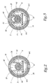
- FIGS. 2 and 3 are plane sections along arrows II-II and III-III indicated in FIG. 1 .
- FIG. 4 is a view in perspective of a part of the installation of FIG. 1 ;
- FIGS. 5 and 6 illustrate a variant of the drive device according to the invention, FIG. 6 being in part a section along plane VI-VI indicated in FIG. 5 .
- FIG. 1 the installation of FIG. 1 comprises a closing or sun-protection screen E, intended to be selectively wound around a substantially horizontal tube T of axis X-X fixed with respect to the masonry of a fixed structure S in which is made an opening O to be obturated with the screen E.
- the winding tube T constitutes a member for displacement of the screen E and is mounted on a device 1 for reversible drive of the screen E.
- This device 1 comprises a head 2 rigidly mounted on the masonry of the structure S. As shown in FIGS. 1 to 4 , this head 2 comprises a solid base 4 in the form of a disc centered on axis X-X and mounted on the masonry and, on the side opposite the structure S, an annular skirt 6 centered on axis X-X.
- front in the following description will mean “directed towards the masonry”, i.e. directed towards the left in FIG. 1 , while the term “rear” corresponds to the opposite direction.
- skirt 6 is shown in solid lines in FIG. 4 , while, in this view, the major part of this skirt should be masked by the base 4 shown solely in dashed and dotted lines.
- the skirt 6 is constituted by a front part 6 A detailed hereinafter and by a cylindrical rear part 6 B of axis X-X.
- the outer face of the rear part 6 B is provided, at its front end, with a projecting rib 6 B 1 which extends over the whole periphery of the skirt. This rib 6 B 1 thus defines with the rest of the outer face of the part 6 B, a shoulder 6 B 2 .
- the front part 6 A of the skirt 6 does not extend, in cross section, over the whole of the circular periphery of the base 4 , but is interrupted in the upper part, i.e. in the upper parts of FIGS. 1 to 3 , with the result that a partition or rib 8 connects the interrupted opposite skirt parts.
- the partition 8 comprises, on the one hand, an axial wall 8 A which projects towards the rear of the base 4 essentially in the direction X-X and which presents a substantially U-shaped cross section ( FIGS. 2 and 3 ) and, on the other hand, a radial wall 8 B parallel to the base 4 , from which the axial wall 8 A projects forwardly and which extends radially upwardly up to the rear part 6 B of the skirt 6 , forming the front end of the rib 6 B 1 .
- the axial wall 8 A is constituted by a front part 8 A 1 and by a rear part 8 A 2 of which the depth, with respect to the level where the front part 6 A of the skirt 6 is interrupted by the partition 8 , is less than that of the front part 8 A 1 .
- a transverse part 8 A 3 connects the front ( 8 A 1 ) and rear ( 8 A 2 ) parts of the axial wall 8 A.
- the partition 8 and the skirt 6 form one piece, integral with the base 4 .
- the head 2 constituted by the base 4 , the skirt 6 and the partition 8 is a one-piece part, preferably made of a synthetic material. This part is, for example, obtained by molding.
- a sleeve 10 of axis X-X is rigidly mounted, for example by force-fitting, around the rear part 6 B of the skirt 6 , being axially wedged against the shoulder 6 B 2 and with the possible interposition of an O-ring or the like (not shown).
- This sleeve internally receives a motor 12 and its associated reduction gear 14 from which extends an output shaft 16 in engagement with a distance piece or a transverse disc 18 of the winding tube T.
- the tube T is supported by the front part 6 A of the skirt 6 , with the interposition of an annular ring 20 centered on the axis X-X and kinematically linked to the tube.
- the ring 20 is provided with an inner toothing 20 A in mesh with a cylindrical double-tooth pinion 22 at its rear toothing 22 A.
- This pinion is mounted to rotate freely about a shaft 24 parallel to axis X-X and supported by the radial wall 8 B of the partition 8 .
- the front toothing 22 B which is of smaller diameter than that of the pinion rear toothing 22 A is in mesh with a toothed wheel 26 mounted to rotate freely about a shaft 28 supported by the base 4 of the head 2 .
- the diameter of the toothing 22 B is smaller than that of the toothing 22 A, such that the movement of rotation of the wheel 26 is geared down with respect to that of the ring 20 , i.e. that of the winding tube T.
- the wall 8 is advantageously dimensioned both so that the depth of the rear part 8 A 2 of the axial wall 8 A is substantially equal to the outer diameter of the rear toothing 22 A of the pinion 22 , for the axial distance separating the base 4 from the transverse part 8 A 3 of the axial wall 8 A to be substantially equal to the axial dimension of the wheel 26 , this ensuring axial wedging of the latter, and so that the axial distance separating the base 4 from the radial wall 8 B is substantially equal to the sum of the axial dimensions of the wheel 26 and the pinion 22 , this ensuring the axial wedging of the pinion.
- the wheel 26 is polarized, i.e. it is provided along its periphery with a succession of magnetic poles, in a predetermined geometry.
- This wheel is for example made of plastoferrite magnetized after injection.
- the device 1 comprises two Hall effect sensors 30 connected to an electronic processing unit 32 . More precisely, the device 1 is equipped with a printed circuit board 34 , connected to the head 2 and projecting from the base 4 in the direction X-X in part below the partition 8 .
- the board is for example slid and retained in appropriate notches 6 A 1 provided on the inner face of the skirt 6 as shown in FIGS. 2 and 3 .
- sensors 30 which, when the board is connected to the head 2 , are disposed substantially in the median transverse plane of the magnet wheel 26 so as to react to the magnetic fields generated by the magnetized zones of the wheel, and, on the other hand, the electronic components of the unit 32 , the sensors 30 being connected to this unit for example by electrical conductors provided in the board 34 .
- the processing unit 32 is adapted to analyze the signals emitted by the Hall effect sensors 30 so as to determine the position and the movement of the magnet wheel 26 and consequently those of the winding tube T, as well as to control, if necessary, the electrical supply of the motor 12 , via a control link 36 .
- the partition 8 defines on either side of its axial ( 8 A) and radial ( 8 B) walls two distinct compartments, namely a first, upwardly open compartment 40 which essentially receives the pinion 22 and the wheel 26 and which is axially closed at the front by the base 4 and at the rear by the radial wall 8 B and, on the other hand, a second compartment 42 closed radially by the skirt 6 , which essentially receives the sensors 30 , the electronic unit 32 and the board 34 and which is closed at the front by the base 4 and open at the rear.
- a first, upwardly open compartment 40 which essentially receives the pinion 22 and the wheel 26 and which is axially closed at the front by the base 4 and at the rear by the radial wall 8 B
- a second compartment 42 closed radially by the skirt 6 , which essentially receives the sensors 30 , the electronic unit 32 and the board 34 and which is closed at the front by the base 4 and open at the rear.
- compartment generally covers any hollow housing which, in transverse section, is defined at least in part by a substantially concave wall.
- these compartments 40 and 42 are advantageously superposed, the axial wall 8 A of the partition 8 being interposed therebetween.
- the space requirement of the device 1 in length is reduced.
- the magnet wheel 26 is axially located between the base 4 and the pinion 22 , the axial space requirement of the compartment 40 is reduced and the sensors 30 located in the compartment 42 are brought as close as possible to the base 4 in order to detect the magnetic fields generated by the wheel so as to disengage a considerable free volume in the compartment 42 to arrange the board 34 and the electronic components of the unit 32 .
- the part 8 A 1 of the wall 8 A is concave seen from the housing 40 and convex seen from the housing 42 . In this way, the wheel 26 is partially surrounded by the partition 8 . In practice, the partition 8 surrounds the wheel 26 over about 180°.
- the housing 40 which is concave around the wheel 26 , is compact and extends only over a relatively small angular sector with respect to the periphery of the skirt 6 .
- the geometry of the partition 8 makes it possible, particularly thanks to its portions 8 A 1 and 8 A 2 , to receive in the housing 40 the transmission formed by elements 22 and 26 which constitute a movement multiplier assembly allowing a detection of the rotation of the tube T with high precision, while this assembly is compact.
- the geometry of the partition 8 also means that the sensors 30 , the board 34 and the unit 32 may be localized in a central part of the tube T. These elements 30 , 32 and 34 therefore do not have to be especially configured to be disposed in the vicinity of the internal wall of the tube which is not planar.
- the device 1 functions as follows:
- the unit 32 controls, if necessary, the stopping or slowing down of the motor 12 , for example if the unit concludes that the screen E has arrived at the end of stroke.
- two Hall effect sensors 30 as in device 1 , it is possible to identify the direction of rotation of the magnet wheel 26 , and consequently that of the winding tube T.
- one sole Hall effect sensor 30 is provided, particularly if the determination of the direction of rotation is not necessary or if it is determined by other means.
- FIGS. 5 and 6 show a variant of the drive device 1 of FIGS. 1 to 3 .
- the magnet wheel 26 is replaced by a disc-shaped optical wheel 50 , which bears over its periphery eight bevelled reflecting surfaces 52 .
- the sensors 30 of the device of FIGS. 1 to 3 are replaced by one or more assemblies constituted by an emitter 54 of light beams and a corresponding receiver 56 connected to a processing unit similar to unit 32 , able to process electronically the signals furnished by this receiver.
- This receiver is adapted to detect the reflection of the light beam emitted by the emitter 54 on one of the reflecting surfaces 52 .
- the tight partition 8 is interposed between the optical wheel 50 and the or each emitter 54 /receiver 56 assemblies, as shown in FIG. 5 .
- the partition 8 or at least that part of the partition located on the path of the light beams, i.e. opposite the emitter 54 and the receiver 56 , is constituted by a material transparent to the light beams employed.
- the partition 8 is in that case made, for example, by means of a molding technique with two materials or by the addition of a transparent welded element.
Landscapes
- Engineering & Computer Science (AREA)
- Structural Engineering (AREA)
- Architecture (AREA)
- Civil Engineering (AREA)
- Operating, Guiding And Securing Of Roll- Type Closing Members (AREA)
- Liquid Crystal (AREA)
- Building Awnings And Sunshades (AREA)
- Power-Operated Mechanisms For Wings (AREA)
Applications Claiming Priority (2)
| Application Number | Priority Date | Filing Date | Title |
|---|---|---|---|
| FR0313546A FR2862334B1 (fr) | 2003-11-19 | 2003-11-19 | Dispositif d'entrainement d'un ecran de fermeture ou de protection solaire et installation comportant un tel dispositif |
| FR0313546 | 2003-11-19 |
Publications (2)
| Publication Number | Publication Date |
|---|---|
| US20050103450A1 US20050103450A1 (en) | 2005-05-19 |
| US7726379B2 true US7726379B2 (en) | 2010-06-01 |
Family
ID=34430020
Family Applications (1)
| Application Number | Title | Priority Date | Filing Date |
|---|---|---|---|
| US10/990,421 Active 2028-03-04 US7726379B2 (en) | 2003-11-19 | 2004-11-18 | Device for driving a closing or sun-protection screen and installation comprising such a device |
Country Status (7)
| Country | Link |
|---|---|
| US (1) | US7726379B2 (de) |
| EP (1) | EP1533465B1 (de) |
| JP (1) | JP4911892B2 (de) |
| CN (1) | CN1619092B (de) |
| AT (1) | ATE546610T1 (de) |
| ES (1) | ES2245276T3 (de) |
| FR (1) | FR2862334B1 (de) |
Cited By (14)
| Publication number | Priority date | Publication date | Assignee | Title |
|---|---|---|---|---|
| US20090260766A1 (en) * | 2008-04-22 | 2009-10-22 | Stephane Lapierre | Method of securely operating a home automation system |
| US20100282890A1 (en) * | 2009-05-05 | 2010-11-11 | Somfy Sas | Tubular actuator for driving a roller blind |
| US20110048655A1 (en) * | 2007-06-07 | 2011-03-03 | Vkr Holding A/S | Screening device with an electronic motion sensor |
| US9334688B2 (en) | 2011-10-03 | 2016-05-10 | Hunter Douglas Inc. | Control of architectural opening coverings |
| US20160143470A1 (en) * | 2013-04-11 | 2016-05-26 | Qmotion Incorporated | Motorized Drapery Apparatus, System and Method of Use |
| US9410371B2 (en) | 2009-01-14 | 2016-08-09 | Hunter Douglas Inc. | Noise dampening motor drive system for retractable covering for architectural openings |
| US9790739B2 (en) | 2010-05-28 | 2017-10-17 | Hunter Douglas Inc. | Architectural opening coverings powered by rotary motors |
| US9834986B2 (en) * | 2012-02-27 | 2017-12-05 | Hunter Douglas Industries B.V. | Architectural covering having a drive mechanism |
| US20180106103A1 (en) * | 2016-01-04 | 2018-04-19 | Boe Technology Group Co., Ltd. | Display apparatus |
| US10030442B2 (en) | 2009-02-09 | 2018-07-24 | Hunter Douglas Industries B.V. | Spring system for roller blinds |
| US10435945B2 (en) | 2014-11-10 | 2019-10-08 | Hunter Douglas Inc. | Covering for an architectural opening including multiple stage spring assembly |
| US10648232B2 (en) | 2012-10-03 | 2020-05-12 | Hunter Douglas Inc. | Methods and apparatus to control an architectural opening covering assembly |
| US11299932B2 (en) * | 2017-10-09 | 2022-04-12 | Hunter Douglas, Inc. | Rail assemblies for motorized architectural coverings and related methods |
| US12123457B2 (en) | 2020-06-03 | 2024-10-22 | Current Products Company, LLC | Splice connector system for architectural covering support rods |
Families Citing this family (9)
| Publication number | Priority date | Publication date | Assignee | Title |
|---|---|---|---|---|
| FR2891001B1 (fr) * | 2005-09-19 | 2007-11-30 | Somfy Sas | Actionneur electrique |
| ITMI20070492A1 (it) * | 2007-03-13 | 2008-09-14 | Faac Spa | Gruppo motore elettrico tubolare adattabile per elementi avvolgibili quali tapparelle e simili |
| ITPN20080055A1 (it) | 2008-06-30 | 2010-01-01 | Nice Spa | Motore tubolare per avvolgibili |
| CN101638974B (zh) | 2008-07-28 | 2011-07-20 | 陈耀华 | 电动卷帘驱动控制器的卷帘位置检测方法及传感装置 |
| JP5069708B2 (ja) * | 2009-02-25 | 2012-11-07 | Ykk Ap株式会社 | 電動シャッター |
| FR3006360B1 (fr) * | 2013-05-31 | 2015-07-03 | Somfy Sas | Procede et dispositif d'actionnement d'un element mobile de fermeture, d'occultation, de protection solaire ou d'ecran |
| DE102014010275A1 (de) * | 2014-07-12 | 2016-01-14 | Novoferm Tormatic Gmbh | Antriebsvorrichtung |
| JP7046677B2 (ja) * | 2018-03-30 | 2022-04-04 | トーソー株式会社 | 基板固定構造を有するヘッドボックス |
| US11649636B2 (en) * | 2018-10-09 | 2023-05-16 | Taylor Made Group, Llc | Tubular motor seal for extendable awning |
Citations (10)
| Publication number | Priority date | Publication date | Assignee | Title |
|---|---|---|---|---|
| US2474358A (en) * | 1941-11-24 | 1949-06-28 | Wellworthy Piston Rings Ltd | Means for lapping taper sided split rings |
| US4417185A (en) * | 1980-04-18 | 1983-11-22 | Somfy | Driving system for roll-up shades, blinds, rolling shutters and the like |
| DE3220441A1 (de) | 1982-05-29 | 1983-12-01 | Eugen 7152 Aspach Seitz | Auf eine welle aufwickelbares rollo |
| US4952830A (en) * | 1988-09-22 | 1990-08-28 | Mitsubishi Denki Kabushiki Kaisha | Brushless motor with hall elements |
| EP0426577A1 (de) | 1989-11-03 | 1991-05-08 | Société Anonyme SIMU | Verfahren und Vorrichtung zum Verstellen einer Verdunkelungsanordnung in justierbaren Positionen und Installation zur Durchführung der Anmeldung |
| US5711360A (en) * | 1996-02-14 | 1998-01-27 | Simu | Operating device for rolling shutter assemblies |
| EP0965724A1 (de) | 1998-06-19 | 1999-12-22 | DEPRAT Jean S.A. | Antriebsvorrichtung einer in zwei Richtungen drehbaren rohrförmigen Walze, Rolladenwalze mit einer derartigen Antriebsvorrichtung, Rolladen mit einer derartigen Walze |
| US6225715B1 (en) * | 1997-07-30 | 2001-05-01 | Oriental Motor Co., Ltd. | Construction of a motor with a built-in sensor |
| US20020045509A1 (en) * | 2000-09-07 | 2002-04-18 | Andre Grauby | Drive device comprising a hydraulic motor and a reduction gear |
| US20020089209A1 (en) * | 2000-12-28 | 2002-07-11 | Matsushita Electric Works, Ltd. | Blind apparatus |
Family Cites Families (11)
| Publication number | Priority date | Publication date | Assignee | Title |
|---|---|---|---|---|
| US3582998A (en) * | 1969-04-10 | 1971-06-08 | Milton Morse | Shower curtain construction |
| US4487244A (en) * | 1981-05-11 | 1984-12-11 | Olson Carl G | Roller apparatus for a flexible web |
| JPH0586784A (ja) * | 1991-09-30 | 1993-04-06 | Toshiba Lighting & Technol Corp | ロールスクリーン昇降装置 |
| US5462105A (en) * | 1992-08-07 | 1995-10-31 | Supernak; Janusz | Adjustments for window shades |
| JP3480600B2 (ja) * | 1994-07-19 | 2003-12-22 | トーソー株式会社 | 電動ロールブラインド |
| US5676415A (en) * | 1994-11-19 | 1997-10-14 | Baumeister + Ostler Gmbh & Co. Kg | Luggage compartment cover for a motor vehicle |
| CN2249817Y (zh) * | 1996-04-03 | 1997-03-19 | 宝崧精密工业股份有限公司 | 立式百叶窗帘的电动控制装置 |
| DE19621009C1 (de) * | 1996-05-24 | 1997-10-09 | Baumeister & Ostler Gmbh Co | Laderaumabdeckung für ein Kraftfahrzeug |
| US6082433A (en) * | 1997-11-21 | 2000-07-04 | Overhead Door Corporation | Control system and method for roll-up door |
| JP4444447B2 (ja) * | 2000-05-12 | 2010-03-31 | 小松電機産業株式会社 | シートシャッタ駆動機構 |
| CN2497029Y (zh) * | 2001-08-31 | 2002-06-26 | 汤湛 | 卷帘门电动升降机 |
-
2003
- 2003-11-19 FR FR0313546A patent/FR2862334B1/fr not_active Expired - Fee Related
-
2004
- 2004-11-17 JP JP2004333198A patent/JP4911892B2/ja not_active Expired - Fee Related
- 2004-11-18 ES ES04356182T patent/ES2245276T3/es not_active Expired - Lifetime
- 2004-11-18 AT AT04356182T patent/ATE546610T1/de active
- 2004-11-18 US US10/990,421 patent/US7726379B2/en active Active
- 2004-11-18 EP EP04356182A patent/EP1533465B1/de not_active Expired - Lifetime
- 2004-11-19 CN CN200410095340.3A patent/CN1619092B/zh not_active Expired - Fee Related
Patent Citations (11)
| Publication number | Priority date | Publication date | Assignee | Title |
|---|---|---|---|---|
| US2474358A (en) * | 1941-11-24 | 1949-06-28 | Wellworthy Piston Rings Ltd | Means for lapping taper sided split rings |
| US4417185A (en) * | 1980-04-18 | 1983-11-22 | Somfy | Driving system for roll-up shades, blinds, rolling shutters and the like |
| DE3220441A1 (de) | 1982-05-29 | 1983-12-01 | Eugen 7152 Aspach Seitz | Auf eine welle aufwickelbares rollo |
| US4952830A (en) * | 1988-09-22 | 1990-08-28 | Mitsubishi Denki Kabushiki Kaisha | Brushless motor with hall elements |
| EP0426577A1 (de) | 1989-11-03 | 1991-05-08 | Société Anonyme SIMU | Verfahren und Vorrichtung zum Verstellen einer Verdunkelungsanordnung in justierbaren Positionen und Installation zur Durchführung der Anmeldung |
| FR2654229A1 (fr) | 1989-11-03 | 1991-05-10 | Simu | Procede et dispositif pour deplacer un element d'occultation jusqu'a des positions stables reglables et installation en faisant application. |
| US5711360A (en) * | 1996-02-14 | 1998-01-27 | Simu | Operating device for rolling shutter assemblies |
| US6225715B1 (en) * | 1997-07-30 | 2001-05-01 | Oriental Motor Co., Ltd. | Construction of a motor with a built-in sensor |
| EP0965724A1 (de) | 1998-06-19 | 1999-12-22 | DEPRAT Jean S.A. | Antriebsvorrichtung einer in zwei Richtungen drehbaren rohrförmigen Walze, Rolladenwalze mit einer derartigen Antriebsvorrichtung, Rolladen mit einer derartigen Walze |
| US20020045509A1 (en) * | 2000-09-07 | 2002-04-18 | Andre Grauby | Drive device comprising a hydraulic motor and a reduction gear |
| US20020089209A1 (en) * | 2000-12-28 | 2002-07-11 | Matsushita Electric Works, Ltd. | Blind apparatus |
Cited By (27)
| Publication number | Priority date | Publication date | Assignee | Title |
|---|---|---|---|---|
| US20110048655A1 (en) * | 2007-06-07 | 2011-03-03 | Vkr Holding A/S | Screening device with an electronic motion sensor |
| US9115538B2 (en) * | 2007-06-07 | 2015-08-25 | Vkr Holding A/S | Screening device with an electronic motion sensor |
| US20090260766A1 (en) * | 2008-04-22 | 2009-10-22 | Stephane Lapierre | Method of securely operating a home automation system |
| US9926741B2 (en) | 2009-01-14 | 2018-03-27 | Hunter Douglas Inc. | Noise dampening motor drive system for retractable covering for architectural openings |
| US10941615B2 (en) | 2009-01-14 | 2021-03-09 | Hunter Douglas, Inc. | Noise dampening motor drive system for retractable covering for architectural openings |
| US9410371B2 (en) | 2009-01-14 | 2016-08-09 | Hunter Douglas Inc. | Noise dampening motor drive system for retractable covering for architectural openings |
| US10030442B2 (en) | 2009-02-09 | 2018-07-24 | Hunter Douglas Industries B.V. | Spring system for roller blinds |
| US11002072B2 (en) | 2009-02-09 | 2021-05-11 | Hunter Douglas Industries B.V. | Spring system for roller blinds |
| US10138678B2 (en) | 2009-02-09 | 2018-11-27 | Hunter Douglas Industries B.V. | Spring system for roller blinds |
| US20100282890A1 (en) * | 2009-05-05 | 2010-11-11 | Somfy Sas | Tubular actuator for driving a roller blind |
| US9175514B2 (en) * | 2009-05-05 | 2015-11-03 | Somfy Sas | Tubular actuator for driving a roller blind |
| US10718159B2 (en) | 2010-05-28 | 2020-07-21 | Hunter Douglas Inc. | Architectural opening coverings powered by rotary motors |
| US9790739B2 (en) | 2010-05-28 | 2017-10-17 | Hunter Douglas Inc. | Architectural opening coverings powered by rotary motors |
| US9334688B2 (en) | 2011-10-03 | 2016-05-10 | Hunter Douglas Inc. | Control of architectural opening coverings |
| US10202802B2 (en) | 2011-10-03 | 2019-02-12 | Hunter Douglas Inc. | Control of architectural opening coverings |
| US10273751B2 (en) | 2011-10-03 | 2019-04-30 | Hunter Douglas Inc. | Methods and apparatus to control architectural opening covering assemblies |
| US9765568B2 (en) | 2011-10-03 | 2017-09-19 | Hunter Douglas Inc. | Methods and apparatus to control architectural opening covering assemblies |
| US10975619B2 (en) | 2011-10-03 | 2021-04-13 | Hunter Douglas Inc. | Methods and apparatus to control architectural opening covering assemblies |
| US9834986B2 (en) * | 2012-02-27 | 2017-12-05 | Hunter Douglas Industries B.V. | Architectural covering having a drive mechanism |
| US10648232B2 (en) | 2012-10-03 | 2020-05-12 | Hunter Douglas Inc. | Methods and apparatus to control an architectural opening covering assembly |
| US9999313B2 (en) * | 2013-04-11 | 2018-06-19 | Current Products Corp. | Motorized drapery apparatus, system and method of use |
| US20160143470A1 (en) * | 2013-04-11 | 2016-05-26 | Qmotion Incorporated | Motorized Drapery Apparatus, System and Method of Use |
| US10435945B2 (en) | 2014-11-10 | 2019-10-08 | Hunter Douglas Inc. | Covering for an architectural opening including multiple stage spring assembly |
| US11459820B2 (en) | 2014-11-10 | 2022-10-04 | Hunter Douglas Inc. | Covering for an architectural opening including multiple stage spring assembly |
| US20180106103A1 (en) * | 2016-01-04 | 2018-04-19 | Boe Technology Group Co., Ltd. | Display apparatus |
| US11299932B2 (en) * | 2017-10-09 | 2022-04-12 | Hunter Douglas, Inc. | Rail assemblies for motorized architectural coverings and related methods |
| US12123457B2 (en) | 2020-06-03 | 2024-10-22 | Current Products Company, LLC | Splice connector system for architectural covering support rods |
Also Published As
| Publication number | Publication date |
|---|---|
| US20050103450A1 (en) | 2005-05-19 |
| ES2245276T3 (es) | 2012-05-23 |
| EP1533465B1 (de) | 2012-02-22 |
| EP1533465A1 (de) | 2005-05-25 |
| ES2245276T1 (es) | 2006-01-01 |
| FR2862334A1 (fr) | 2005-05-20 |
| ATE546610T1 (de) | 2012-03-15 |
| CN1619092B (zh) | 2010-09-01 |
| JP2005146842A (ja) | 2005-06-09 |
| CN1619092A (zh) | 2005-05-25 |
| JP4911892B2 (ja) | 2012-04-04 |
| FR2862334B1 (fr) | 2006-02-10 |
Similar Documents
| Publication | Publication Date | Title |
|---|---|---|
| US7726379B2 (en) | Device for driving a closing or sun-protection screen and installation comprising such a device | |
| US5039942A (en) | Cable supporting insert closing an opening in the housing of an inductive rotational speed sensor | |
| US8258993B2 (en) | Remote-controlled light receiving structure of electric roll screen for blind | |
| KR100675394B1 (ko) | 도어 개폐장치 및 전자 클러치 및 연결구조 | |
| JP2003047204A (ja) | 駆動装置 | |
| KR20080055814A (ko) | 차량용 전동 보조 드라이브 | |
| JP3015637B2 (ja) | 駆動モータ及びパワーウインドウモータ | |
| JP2021530707A (ja) | 回転角度測定システム | |
| CN116488402A (zh) | 编码器及电机 | |
| JP5433208B2 (ja) | ギヤボックスの駆動機構 | |
| JP2000121385A (ja) | モ―タ回転位置検出装置 | |
| WO2019065505A1 (ja) | 電動アクチュエータ | |
| CN216252449U (zh) | 一种飞轮系统及减摇陀螺 | |
| JP3586683B2 (ja) | パワーウインドウ駆動モータ | |
| JP4137296B2 (ja) | モータ | |
| JP2002257585A (ja) | モータアクチュエータ | |
| KR200181542Y1 (ko) | 윈도우 리프트 모터의 링 마그네트 장착구조 | |
| US20190319559A1 (en) | Unknown | |
| JP4121108B2 (ja) | 小型モータ | |
| JP3677020B2 (ja) | パワーウインドウ駆動モータ | |
| JP3312442B2 (ja) | ロールスクリーンのロールパイプ回転角度検出装置 | |
| JPH025666Y2 (de) | ||
| JP3182340B2 (ja) | 駆動装置 | |
| JP3039977U (ja) | 自動扉の動力装置 | |
| KR100446190B1 (ko) | 차량시스템용전기작동기 |
Legal Events
| Date | Code | Title | Description |
|---|---|---|---|
| AS | Assignment |
Owner name: SOMFY, FRANCE Free format text: ASSIGNMENT OF ASSIGNORS INTEREST;ASSIGNOR:BEAU, STEPHANE;REEL/FRAME:016008/0447 Effective date: 20041115 Owner name: SOMFY,FRANCE Free format text: ASSIGNMENT OF ASSIGNORS INTEREST;ASSIGNOR:BEAU, STEPHANE;REEL/FRAME:016008/0447 Effective date: 20041115 |
|
| STCF | Information on status: patent grant |
Free format text: PATENTED CASE |
|
| FPAY | Fee payment |
Year of fee payment: 4 |
|
| MAFP | Maintenance fee payment |
Free format text: PAYMENT OF MAINTENANCE FEE, 8TH YEAR, LARGE ENTITY (ORIGINAL EVENT CODE: M1552) Year of fee payment: 8 |
|
| MAFP | Maintenance fee payment |
Free format text: PAYMENT OF MAINTENANCE FEE, 12TH YEAR, LARGE ENTITY (ORIGINAL EVENT CODE: M1553); ENTITY STATUS OF PATENT OWNER: LARGE ENTITY Year of fee payment: 12 |