EP1533465A1 - Antrieb für einen Verschluss- oder Sonnenschutzvorhang und Vorrichtung mit einem derartigen Antrieb - Google Patents
Antrieb für einen Verschluss- oder Sonnenschutzvorhang und Vorrichtung mit einem derartigen Antrieb Download PDFInfo
- Publication number
- EP1533465A1 EP1533465A1 EP04356182A EP04356182A EP1533465A1 EP 1533465 A1 EP1533465 A1 EP 1533465A1 EP 04356182 A EP04356182 A EP 04356182A EP 04356182 A EP04356182 A EP 04356182A EP 1533465 A1 EP1533465 A1 EP 1533465A1
- Authority
- EP
- European Patent Office
- Prior art keywords
- compartment
- tube
- partition
- screen
- head
- Prior art date
- Legal status (The legal status is an assumption and is not a legal conclusion. Google has not performed a legal analysis and makes no representation as to the accuracy of the status listed.)
- Granted
Links
- 238000005192 partition Methods 0.000 claims abstract description 29
- 238000006073 displacement reaction Methods 0.000 claims abstract description 16
- 238000012545 processing Methods 0.000 claims abstract description 12
- 238000009434 installation Methods 0.000 claims abstract description 11
- 238000004804 winding Methods 0.000 claims abstract description 8
- 230000037072 sun protection Effects 0.000 claims abstract description 4
- 230000005540 biological transmission Effects 0.000 claims description 7
- 238000001514 detection method Methods 0.000 claims description 7
- 230000009347 mechanical transmission Effects 0.000 claims 2
- 230000033001 locomotion Effects 0.000 description 7
- 230000005355 Hall effect Effects 0.000 description 6
- 239000000463 material Substances 0.000 description 5
- XLYOFNOQVPJJNP-UHFFFAOYSA-N water Substances O XLYOFNOQVPJJNP-UHFFFAOYSA-N 0.000 description 4
- 238000000034 method Methods 0.000 description 3
- 238000000465 moulding Methods 0.000 description 3
- 239000004020 conductor Substances 0.000 description 2
- 230000003287 optical effect Effects 0.000 description 2
- 238000007789 sealing Methods 0.000 description 2
- 239000000243 solution Substances 0.000 description 2
- 230000000475 sunscreen effect Effects 0.000 description 2
- 239000000516 sunscreening agent Substances 0.000 description 2
- 238000012549 training Methods 0.000 description 2
- 238000004026 adhesive bonding Methods 0.000 description 1
- 239000003638 chemical reducing agent Substances 0.000 description 1
- 230000003247 decreasing effect Effects 0.000 description 1
- 238000013461 design Methods 0.000 description 1
- 238000011161 development Methods 0.000 description 1
- 238000002347 injection Methods 0.000 description 1
- 239000007924 injection Substances 0.000 description 1
- 238000004519 manufacturing process Methods 0.000 description 1
- 238000005259 measurement Methods 0.000 description 1
- 230000036961 partial effect Effects 0.000 description 1
- 230000000149 penetrating effect Effects 0.000 description 1
- 230000035515 penetration Effects 0.000 description 1
- 230000002093 peripheral effect Effects 0.000 description 1
- 230000002085 persistent effect Effects 0.000 description 1
- 230000002829 reductive effect Effects 0.000 description 1
- 239000011347 resin Substances 0.000 description 1
- 229920005989 resin Polymers 0.000 description 1
- 230000000717 retained effect Effects 0.000 description 1
- 230000002441 reversible effect Effects 0.000 description 1
- 210000003625 skull Anatomy 0.000 description 1
- 239000007787 solid Substances 0.000 description 1
- 125000006850 spacer group Chemical group 0.000 description 1
- 229920002994 synthetic fiber Polymers 0.000 description 1
Images


Classifications
-
- E—FIXED CONSTRUCTIONS
- E06—DOORS, WINDOWS, SHUTTERS, OR ROLLER BLINDS IN GENERAL; LADDERS
- E06B—FIXED OR MOVABLE CLOSURES FOR OPENINGS IN BUILDINGS, VEHICLES, FENCES OR LIKE ENCLOSURES IN GENERAL, e.g. DOORS, WINDOWS, BLINDS, GATES
- E06B9/00—Screening or protective devices for wall or similar openings, with or without operating or securing mechanisms; Closures of similar construction
- E06B9/56—Operating, guiding or securing devices or arrangements for roll-type closures; Spring drums; Tape drums; Counterweighting arrangements therefor
- E06B9/68—Operating devices or mechanisms, e.g. with electric drive
- E06B9/72—Operating devices or mechanisms, e.g. with electric drive comprising an electric motor positioned inside the roller
-
- E—FIXED CONSTRUCTIONS
- E06—DOORS, WINDOWS, SHUTTERS, OR ROLLER BLINDS IN GENERAL; LADDERS
- E06B—FIXED OR MOVABLE CLOSURES FOR OPENINGS IN BUILDINGS, VEHICLES, FENCES OR LIKE ENCLOSURES IN GENERAL, e.g. DOORS, WINDOWS, BLINDS, GATES
- E06B9/00—Screening or protective devices for wall or similar openings, with or without operating or securing mechanisms; Closures of similar construction
- E06B9/56—Operating, guiding or securing devices or arrangements for roll-type closures; Spring drums; Tape drums; Counterweighting arrangements therefor
- E06B9/68—Operating devices or mechanisms, e.g. with electric drive
- E06B2009/6809—Control
- E06B2009/6872—Control using counters to determine shutter position
Definitions
- the present invention relates to a device drive a closing screen or protection solar energy, as well as a closure or sun protection incorporating such a device.
- Closure means doors, gates, shutters, grilles and equivalent materials.
- a screen which can be a flexible apron or a rigid or semi-rigid panel, is moved next to an opening to close selectively this one.
- the above-mentioned device is satisfactory to its function of automatic control of the training of the screen, it has a disadvantage as to its tightness, especially as to the tightness of the unit electronic treatment it contains. Indeed, this type of device is likely to be installed at outside and so be subjected to bad weather. It results in significant risks of water seeping inside the tube and thus reach the unit electronic processing and the electric motor, especially by the opening necessary for kinematic links between the transmission means and the ring.
- one or more joints may be interposed between the ring and the head fixed and we can try to adjust the ring better around the fixed head.
- These solutions are not economical because they require larger pieces, particular geometries to level of the elements in contact and / or a method of assembly complex.
- the crown of magnets is expensive and the precision of the measurement depends on the angular difference between the magnets peripheral devices. This difference being fixed by the diameter of the support that depends on the type of engine used, it can only not be easily adjusted.
- US-A-4,952,830 proposes to drown in a suitable resin electronic detection sensors the displacement of the rotor of an engine, these sensors being kinematically related to the stator.
- the sealing of the sensors is thus ensured but this solution does not guarantee the sealing of the conductors connecting the sensors to a electronic signal processing unit provided by these sensors.
- the potential problems do not affect the sensors as such but are reported on more electronic components away from the processing unit.
- the object of the present invention is to propose a device of the aforementioned type, in which the parts of the device sensitive to water are effectively protected, in particular the electronic components of this device.
- the subject of the invention is a device drive a closing screen or protection solar energy system, comprising a geared motor unit, an moving the screen, controlled in rotation around a axis by the geared motor group, a fixed head mounted on a supporting structure and supporting the tube winding and unwinding, a representative piece the position and / or displacement of the tube and bound kinematically to this tube by transmission means mechanical means, and position detecting means and / or of the displacement of the representative piece, connected to a electronic processing unit adapted to determine the position and / or displacement of the tube, characterized in that it further comprises a watertight partition secured to the head, which delimits at least in part, on one side, a first compartment for receiving at least one room representative and, on the other hand, a second compartment receiving at least the electronic processing unit.
- the bulkhead of the device according to the invention tightly delineates hollow dwellings respective parts for the representative moving part of the position and / or displacement of the tube and for at least the electronic unit sensitive to humidity and to water from outside the device.
- This partition being secured to the head, it is fixed by compared to the supporting structure and therefore requires no significant mechanical development. Moreover, it does not complicate not the mounting and installation of the device.
- the subject of the invention is also a plant of closure or sunscreen, which includes a screen adapted to be driven by a device as defined above.
- Figure 1 The installation of Figure 1 includes a screen E of closure or sunscreen, intended to be selectively wrapped around a substantially T tube horizontal and X-X axis fixed relative to the masonry of a fixed structure S in which is arranged a opening O to close with the screen E.
- the winding tube T constitutes a displacement member of the screen E and is mounted on a device 1 of reversible drive of skull.
- This device 1 comprises a head 2 mounted rigidly on the masonry of the structure S. As shown on FIGS. 1 to 4, this head 2 comprises a solid base 4 disc-shaped centered on the X-X axis and mounted on the masonry and, on the opposite side to the S structure, a skirt ring 6 centered on the X-X axis.
- the skirt 6 consists of a front portion 6A detailed below and a cylindrical rear part 6B X-X axis.
- the outer face of the rear portion 6B is provided at its front end with a protruding rib 6B1 which extends over the entire periphery of the skirt. This rib 6B1 thus delimits with the rest of the face outer portion of portion 6B a shoulder 6B2.
- the part front 6A of the skirt 6 does not extend, in section across the circular periphery of the base 4 but is interrupted in the upper part, that is to say in the upper parts of Figures 1 to 3, such so that a partition or rib 8 connects the parts of skirt opposite interrupted.
- the partition 8 comprises, on the one hand, an axial wall 8A which extends projecting towards the rear of the base 4 basically in the X-X direction and that presents a cross-section in the overall shape of U (FIG. and 3) and, on the other hand, a radial wall 8B parallel to the base 4, from which the axial wall 8A extends in protruding forward and extending radially towards the up to the rear portion 6B of the skirt 6, forming the front end of rib 6B1.
- the axial wall 8A consists of a front part 8A1 and a rear portion 8A2 whose depth, by ratio at the level where the front portion 6A of the skirt 6 is interrupted by the partition 8, is smaller than that of the front part 8A1.
- a transverse part 8A3 connects the front parts 8A1 and rear 8A2 of the axial wall 8A.
- the partition 8 and the skirt 6 form a piece in one piece, come matter with the base 4.
- the head 2 constituted of the base 4, the skirt 6 and the partition 8 is a single piece, preferably made in one synthetic material. This piece is for example obtained by molding.
- a sheath 10 of X-X axis is rigidly mounted by example by interlocking in force, around the part rear 6B of the skirt 6, being wedged axially against the shoulder 6B2 and with possible interposition of a seal or the like not shown.
- This sheath internally receives a motor 12 and its associated reducer 14 from which extends an output shaft 16 in mesh with a spacer or transverse disc 18 of the tube T.
- the tube T is supported by the front portion 6A of the skirt 6, with interposition of an annular ring 20 centered on the X-X axis and kinematically linked to the tube.
- the ring 20 is provided with an internal toothing 20A in engagement with a cylindrical pinion gear 22 with double teeth, level of its rear teeth 22A of larger diameter.
- This pinion is rotatably mounted about an axis 24 parallel to the X-X axis and supported by the radial wall 8B of the partition 8.
- the toothing before 22B of smaller pinion diameter 22 is engaged with a toothed wheel 26 free mounting in rotation about an axis 28 supported by the base 4 of the head 2.
- the diameter of the toothing 22B being smaller than that of the toothing 22A, the movement of rotation of the wheel 26 is multiplied compared to that of the ring 20, that is to say that of the winding tube T.
- the wall 8 is dimensioned both for the depth of the rear part 8A2 of the axial wall 8A is substantially equal to the outer diameter of the toothing rear 22A of the pinion 22, so that the axial distance separating the base 4 from the transverse portion 8A3 of the axial wall 8A is substantially equal to the dimension axial axis of the wheel 26, which ensures the axial setting of the latter, and so that the axial distance separating the base 4 of the radial wall 8B is substantially equal to the sum of the axial dimensions of the wheel 26 and the pinion 22, which ensures the axial setting of the pinion.
- the wheel 26 is polarized, that is to say it is provided along its periphery with a succession of poles magnetic, according to a predetermined geometry.
- This wheel is for example made in magnetized plastoferrite after injection.
- the device 1 comprises two sensors 30 Hall effects connected to an electronic processing unit 32. More specifically, the device 1 is equipped with a plate 34 of printed circuits, secured to the head 2 and extending projecting from the base 4 in the direction X-X partly below the bulkhead 8. The plate is for example slipped and retained in notches 6A1 suitable on the inside of the skirt 6 as shown in Figures 2 and 3.
- the sensors 30 which, when the plate is secured to the head 2, are arranged substantially in the median transverse plane of the polar wheel 26 so as to react to magnetic fields generated by the magnetized zones of the wheel, and, on the other hand, part, the electronic components of Unit 32, the sensors 30 being connected to this unit for example by electrical conductors provided in the wafer 34.
- the processing unit 32 is adapted to analyze the signals emitted by the Hall effect sensors 30 so as to determine the position and movement of the polar wheel 26 and thereby those of the winding tube T, as well as for order if necessary the power supply of the motor 12, via a control link 36.
- the partition 8 defines from else of its axial walls 8A and radial 8B two separate compartments, namely a first compartment 40 open up, which basically receives the pinion 22 and the wheel 26 and which is axially closed to the front by the base 4 and at the back by the radial wall 8B and, secondly, a second compartment 42 closed radially by the skirt 6, which essentially receives the sensors 30, the electronic unit 32 and the plate 34 and which is closed at the front by the base 4 and open to the rear.
- a first compartment 40 open up which basically receives the pinion 22 and the wheel 26 and which is axially closed to the front by the base 4 and at the back by the radial wall 8B and, secondly, a second compartment 42 closed radially by the skirt 6, which essentially receives the sensors 30, the electronic unit 32 and the plate 34 and which is closed at the front by the base 4 and open to the rear.
- compartment covers generally any hollow housing which, in section cross-section is delimited at least in part by a wall overall concave.
- these compartments 40 and 42 are superimposed, the axial wall 8A partition 8 being interposed between them.
- the overall length of the device 1 is reduced.
- the axial size of the compartment 40 is decreased and the sensors 30 located in the compartment 42 are brought closer to the base 4 to detect the magnetic fields generated by the wheel of to release a significant free volume in the compartment 42 to arrange the plate 34 and the electronic components of the unit 32.
- integrally molding the base 4, the skirt 6 and the partition we get a piece that determines both the position of the polar wheel 26 and the position of the sensors 30, which makes it possible to better control the tolerances determining the relative positioning of the wheel and sensors.
- Part 8A1 of the wall 8A is concave seen from housing 40 and convex view of housing 42.
- the wheel 26 is partially surrounded by the partition 8.
- the partition 8 surrounds the wheel 26 about 180 °.
- the housing 40 which is concave around the wheel 26, is compact and only extends over an angular sector relatively small compared to the periphery of the skirt 6.
- the geometry of the partition 8 allows, thanks to its portions 8A1 and 8A2, to receive in the housing 40 the transmission formed of elements 22 and 26 constituting a multiplier of motion allowing a detection of the rotation of the tube T with a large accuracy, while this set is compact.
- the geometry of the partition 8 also induces that the 30, the plate 34 and the unit 32 can be located in a central part of the tube T. These elements 30, 32 and 34 do not have to be specially configured to be arranged in the vicinity of the inner wall of the tube which is not flat.
- the operation of the device 1 is as follows:
- the screen E When the screen E is wrapped around the tube T or unrolled from this tube, it rotates following a corresponding movement the annular ring 20 whose movement is transmitted to the polar wheel 26 via the pinion 22.
- the position and displacement of this wheel, representative of the position and displacement of the tube T, are detected by the sensors 30 whose signals are transmitted to the processing unit 32 which then determines by calculates the position and displacement of the tube.
- the unit 32 In function pre-determined parameter setting, the unit 32 then commands if necessary the stopping or slowing down of the engine 12, for example if the unit finishes at the end of the race of the screen E.
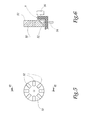
- Figures 5 and 6 show a variant of 1 of Figures 1 to 3.
- the wheel 26 is replaced by a wheel optical disk-shaped 50, which carries according to its periphery eight reflective bevelled surfaces 52.
- the sensors 30 of the device of FIGS. 1 to 3 are replaced by one or more sets consisting of a transmitter 54 of light beams and a corresponding receiver 56 connected to a processing unit similar to unit 32, able to process electronically the signals provided by this receiver.
- This receiver is adapted to detect the reflection of the emitted light beam by the transmitter 54 on one of the reflecting surfaces 52.
- the bulkhead 8 is interposed between the optical wheel 50 and the assembly or sets transmitter 54 - receiver 56, as shown in FIG. 5.
- Partition 8 or at least the partition part located on the path of the light beams, that is to say next to transmitter 54 and receiver 56, is made of a material transparent to light beams employees.
- the partition 8 is then for example made to the by means of a bi-material molding technique or by supply of a transparent welded element.
Landscapes
- Engineering & Computer Science (AREA)
- Structural Engineering (AREA)
- Architecture (AREA)
- Civil Engineering (AREA)
- Operating, Guiding And Securing Of Roll- Type Closing Members (AREA)
- Liquid Crystal (AREA)
- Building Awnings And Sunshades (AREA)
- Power-Operated Mechanisms For Wings (AREA)
Applications Claiming Priority (2)
| Application Number | Priority Date | Filing Date | Title |
|---|---|---|---|
| FR0313546A FR2862334B1 (fr) | 2003-11-19 | 2003-11-19 | Dispositif d'entrainement d'un ecran de fermeture ou de protection solaire et installation comportant un tel dispositif |
| FR0313546 | 2003-11-19 |
Publications (2)
| Publication Number | Publication Date |
|---|---|
| EP1533465A1 true EP1533465A1 (de) | 2005-05-25 |
| EP1533465B1 EP1533465B1 (de) | 2012-02-22 |
Family
ID=34430020
Family Applications (1)
| Application Number | Title | Priority Date | Filing Date |
|---|---|---|---|
| EP04356182A Expired - Lifetime EP1533465B1 (de) | 2003-11-19 | 2004-11-18 | Antrieb für einen Verschluss- oder Sonnenschutzvorhang und Vorrichtung mit einem derartigen Antrieb |
Country Status (7)
| Country | Link |
|---|---|
| US (1) | US7726379B2 (de) |
| EP (1) | EP1533465B1 (de) |
| JP (1) | JP4911892B2 (de) |
| CN (1) | CN1619092B (de) |
| AT (1) | ATE546610T1 (de) |
| ES (1) | ES2245276T3 (de) |
| FR (1) | FR2862334B1 (de) |
Cited By (2)
| Publication number | Priority date | Publication date | Assignee | Title |
|---|---|---|---|---|
| WO2008110334A1 (en) * | 2007-03-13 | 2008-09-18 | Faac S.P.A. | Adjustable tubular electric motor unit for roll-up elements such as blinds and similar items |
| WO2010000598A2 (en) | 2008-06-30 | 2010-01-07 | Nice S.P.A. | Tubular motor for roll-up shutters and the like |
Families Citing this family (21)
| Publication number | Priority date | Publication date | Assignee | Title |
|---|---|---|---|---|
| FR2891001B1 (fr) * | 2005-09-19 | 2007-11-30 | Somfy Sas | Actionneur electrique |
| ATE480688T1 (de) * | 2007-06-07 | 2010-09-15 | Vkr Holding As | Wickelwelle mit rohrmotor und elektronischem bewegungssensor |
| FR2930276B1 (fr) * | 2008-04-22 | 2010-05-28 | Somfy Sas | Procede de fonctionnement securise d'un systeme domotique. |
| CN101638974B (zh) | 2008-07-28 | 2011-07-20 | 陈耀华 | 电动卷帘驱动控制器的卷帘位置检测方法及传感装置 |
| US8307878B2 (en) | 2009-01-14 | 2012-11-13 | Hunter Douglas Inc. | Noise dampening motor drive system for retractable covering for architectural openings |
| CN102308056B (zh) | 2009-02-09 | 2015-08-05 | 亨特·道格拉斯私人有限公司 | 用于卷帘的弹簧系统 |
| JP5069708B2 (ja) * | 2009-02-25 | 2012-11-07 | Ykk Ap株式会社 | 電動シャッター |
| FR2945314B1 (fr) * | 2009-05-05 | 2011-07-01 | Somfy Sas | Actionneur tubulaire d'entrainement d'un volet roulant |
| DK2575558T3 (en) | 2010-05-28 | 2019-04-01 | Hunter Douglas | COVERINGS FOR ARCHITECTURAL OPENINGS OPERATED BY ROTATING ENGINES |
| EP2763572A4 (de) | 2011-10-03 | 2015-12-09 | Hunter Douglas | Verfahren und vorrichtung zur steuerung von abdeckungsanordnungen für gebäudeöffnungen |
| NL1039407C2 (en) * | 2012-02-27 | 2013-08-28 | Hunter Douglas Ind Bv | Architectural covering having a drive mechanism for extending and retracting a covering member between opposite first and second end positions. |
| CA2828819C (en) | 2012-10-03 | 2020-03-10 | Hunter Douglas Inc. | Methods and apparatus to control an architectural opening covering assembly |
| US9999313B2 (en) * | 2013-04-11 | 2018-06-19 | Current Products Corp. | Motorized drapery apparatus, system and method of use |
| FR3006360B1 (fr) * | 2013-05-31 | 2015-07-03 | Somfy Sas | Procede et dispositif d'actionnement d'un element mobile de fermeture, d'occultation, de protection solaire ou d'ecran |
| DE102014010275A1 (de) * | 2014-07-12 | 2016-01-14 | Novoferm Tormatic Gmbh | Antriebsvorrichtung |
| US10435945B2 (en) | 2014-11-10 | 2019-10-08 | Hunter Douglas Inc. | Covering for an architectural opening including multiple stage spring assembly |
| CN105489123A (zh) * | 2016-01-04 | 2016-04-13 | 京东方科技集团股份有限公司 | 一种显示装置 |
| CA3019986A1 (en) * | 2017-10-09 | 2019-04-09 | Hunter Douglas Inc. | Rail assemblies for motorized architectural coverings and related methods |
| JP7046677B2 (ja) * | 2018-03-30 | 2022-04-04 | トーソー株式会社 | 基板固定構造を有するヘッドボックス |
| US11649636B2 (en) * | 2018-10-09 | 2023-05-16 | Taylor Made Group, Llc | Tubular motor seal for extendable awning |
| US12123457B2 (en) | 2020-06-03 | 2024-10-22 | Current Products Company, LLC | Splice connector system for architectural covering support rods |
Citations (2)
| Publication number | Priority date | Publication date | Assignee | Title |
|---|---|---|---|---|
| DE3220441A1 (de) * | 1982-05-29 | 1983-12-01 | Eugen 7152 Aspach Seitz | Auf eine welle aufwickelbares rollo |
| FR2654229A1 (fr) * | 1989-11-03 | 1991-05-10 | Simu | Procede et dispositif pour deplacer un element d'occultation jusqu'a des positions stables reglables et installation en faisant application. |
Family Cites Families (19)
| Publication number | Priority date | Publication date | Assignee | Title |
|---|---|---|---|---|
| US2474358A (en) * | 1941-11-24 | 1949-06-28 | Wellworthy Piston Rings Ltd | Means for lapping taper sided split rings |
| US3582998A (en) * | 1969-04-10 | 1971-06-08 | Milton Morse | Shower curtain construction |
| FR2480846A1 (fr) * | 1980-04-18 | 1981-10-23 | Carpano & Pons | Dispositif d'entrainement, pour stores a rouleau, volets roulants, ou similaires |
| US4487244A (en) * | 1981-05-11 | 1984-12-11 | Olson Carl G | Roller apparatus for a flexible web |
| JPH0287959A (ja) * | 1988-09-22 | 1990-03-28 | Mitsubishi Electric Corp | ブラシレスモータ |
| JPH0586784A (ja) * | 1991-09-30 | 1993-04-06 | Toshiba Lighting & Technol Corp | ロールスクリーン昇降装置 |
| US5462105A (en) * | 1992-08-07 | 1995-10-31 | Supernak; Janusz | Adjustments for window shades |
| JP3480600B2 (ja) * | 1994-07-19 | 2003-12-22 | トーソー株式会社 | 電動ロールブラインド |
| US5676415A (en) * | 1994-11-19 | 1997-10-14 | Baumeister + Ostler Gmbh & Co. Kg | Luggage compartment cover for a motor vehicle |
| FR2744759B1 (fr) * | 1996-02-14 | 1998-04-17 | Simu | Dispositif de manoeuvre pour volet roulant |
| CN2249817Y (zh) * | 1996-04-03 | 1997-03-19 | 宝崧精密工业股份有限公司 | 立式百叶窗帘的电动控制装置 |
| DE19621009C1 (de) * | 1996-05-24 | 1997-10-09 | Baumeister & Ostler Gmbh Co | Laderaumabdeckung für ein Kraftfahrzeug |
| JPH1155902A (ja) * | 1997-07-30 | 1999-02-26 | Oriental Motor Co Ltd | センサ組み込みモータの構造 |
| US6082433A (en) * | 1997-11-21 | 2000-07-04 | Overhead Door Corporation | Control system and method for roll-up door |
| FR2780090B1 (fr) | 1998-06-19 | 2000-08-11 | Deprat Jean Sa | Dispositif d'entrainement d'un organe, notamment tambour de volet roulant, et dispositif de protection d'une ouverture, notamment volet roulant, equipe d'un dispositif d'entrainement |
| JP4444447B2 (ja) * | 2000-05-12 | 2010-03-31 | 小松電機産業株式会社 | シートシャッタ駆動機構 |
| FR2813652B1 (fr) * | 2000-09-07 | 2003-06-20 | Poclain Hydraulics Ind | Dispositif d'entrainement comprenant un moteur hydraulique et un reducteur |
| JP3662847B2 (ja) * | 2000-12-28 | 2005-06-22 | 松下電工株式会社 | ブラインド装置 |
| CN2497029Y (zh) * | 2001-08-31 | 2002-06-26 | 汤湛 | 卷帘门电动升降机 |
-
2003
- 2003-11-19 FR FR0313546A patent/FR2862334B1/fr not_active Expired - Fee Related
-
2004
- 2004-11-17 JP JP2004333198A patent/JP4911892B2/ja not_active Expired - Fee Related
- 2004-11-18 ES ES04356182T patent/ES2245276T3/es not_active Expired - Lifetime
- 2004-11-18 AT AT04356182T patent/ATE546610T1/de active
- 2004-11-18 US US10/990,421 patent/US7726379B2/en active Active
- 2004-11-18 EP EP04356182A patent/EP1533465B1/de not_active Expired - Lifetime
- 2004-11-19 CN CN200410095340.3A patent/CN1619092B/zh not_active Expired - Fee Related
Patent Citations (2)
| Publication number | Priority date | Publication date | Assignee | Title |
|---|---|---|---|---|
| DE3220441A1 (de) * | 1982-05-29 | 1983-12-01 | Eugen 7152 Aspach Seitz | Auf eine welle aufwickelbares rollo |
| FR2654229A1 (fr) * | 1989-11-03 | 1991-05-10 | Simu | Procede et dispositif pour deplacer un element d'occultation jusqu'a des positions stables reglables et installation en faisant application. |
Cited By (5)
| Publication number | Priority date | Publication date | Assignee | Title |
|---|---|---|---|---|
| WO2008110334A1 (en) * | 2007-03-13 | 2008-09-18 | Faac S.P.A. | Adjustable tubular electric motor unit for roll-up elements such as blinds and similar items |
| CN101680265B (zh) * | 2007-03-13 | 2012-08-08 | Faac股份公司 | 如百叶窗和类似件的卷起元件的可调节管状电动马达单元 |
| US8513845B2 (en) | 2007-03-13 | 2013-08-20 | Faac S.P.A. | Adjustable tubular electric motor unit for roll-up elements such as blinds and similar items |
| WO2010000598A2 (en) | 2008-06-30 | 2010-01-07 | Nice S.P.A. | Tubular motor for roll-up shutters and the like |
| WO2010000598A3 (en) * | 2008-06-30 | 2010-08-05 | Nice S.P.A. | Tubular motor for roll-up shutters and the like |
Also Published As
| Publication number | Publication date |
|---|---|
| US7726379B2 (en) | 2010-06-01 |
| US20050103450A1 (en) | 2005-05-19 |
| ES2245276T3 (es) | 2012-05-23 |
| EP1533465B1 (de) | 2012-02-22 |
| ES2245276T1 (es) | 2006-01-01 |
| FR2862334A1 (fr) | 2005-05-20 |
| ATE546610T1 (de) | 2012-03-15 |
| CN1619092B (zh) | 2010-09-01 |
| JP2005146842A (ja) | 2005-06-09 |
| CN1619092A (zh) | 2005-05-25 |
| JP4911892B2 (ja) | 2012-04-04 |
| FR2862334B1 (fr) | 2006-02-10 |
Similar Documents
| Publication | Publication Date | Title |
|---|---|---|
| EP1533465B1 (de) | Antrieb für einen Verschluss- oder Sonnenschutzvorhang und Vorrichtung mit einem derartigen Antrieb | |
| EP0814338B1 (de) | Schwenkkugellager mit eingebautem Messaufnehmer | |
| EP2248988A1 (de) | Aufhängung eines Torflügels für abschüssiges Gelände | |
| EP0194930A2 (de) | Elektrooptische Torsionsmessvorrichtung für einen Antriebsmechanismus | |
| EP2710215B1 (de) | Elektromechanischer aktuator-kopf zur handhabung eines aufroll-elements | |
| EP0753727A1 (de) | Gerät zur Messung des Drehmomentes, insbesondere für einen Getriebemotor zur Aktivierung eines funktionellen Elementes eines Kraftfahrzeuges | |
| EP3418483B1 (de) | Regulierungsverfahren der motorisierten antriebsvorrichtung eines drehtors | |
| EP0229681A2 (de) | Antriebsvorrichtung zum Drehen der Rolle eines Rolladens, Rollstores oder dergleichen | |
| EP4335719A1 (de) | Vorrichtung zur erkennung von eisenbahnverkehr | |
| WO2022171840A1 (fr) | Module de nettoyage d'un dispositif de protection d'un élément optique | |
| EP0461992B1 (de) | Messaufnehmer, insbesondere Geschwindigkeitsmessaufnehmer für Kraftfahrzeuge | |
| EP0468890B1 (de) | Verschlussvorrichtung für einen Strahl, der einen bestimmten Punkt zu treffen hat | |
| FR3001538A1 (fr) | Ensemble instrumente pour systeme tournant. | |
| FR2855296A1 (fr) | Photocellule orientale, anti-vandale et etanche | |
| EP3772804B1 (de) | Motorisierungs- und antriebseinheit einer abdeckung für ein schwimmbadbecken | |
| FR2943089A1 (fr) | Module de commande d'un ouvrant de serre | |
| FR2807781A1 (fr) | Bati dormant comprenant un ensemble d'entrainement de volets battants | |
| WO2017020945A1 (fr) | Dispositif et procédé pour la commande d'une ouverture à lames pivotantes | |
| EP1722206B1 (de) | Bewegungssensor mit einstellbarem Detektionsbereich | |
| FR2650889A1 (fr) | Appareil pour la detection du balourd d'une roue d'automobile en vue de l'equilibrage de celle-ci, et capteur potentiometrique destine a equiper un tel appareil | |
| FR2695677A1 (fr) | Dispositif de mesure de la position d'une poutre d'alimentation d'un dispositif de perçage de rocher et/ou de mesure de la position d'un perforateur de rocher. | |
| WO2017006050A1 (fr) | Dispositif de detection d'une position neutre d'une commande de vitesses d'une boite de vitesses d'un vehicule automobile | |
| EP1231355A1 (de) | Vorrichtung zur Immobilisierung einer Antriebsvorrichtung und Bedienungseinheit eines Verschlusses oder einer Sonnenschutzanlage mit einer solchen Anordnung | |
| FR3099443A1 (fr) | Système de détection optique pour véhicule automobile | |
| FR2888610A1 (fr) | Dispositif domotique de mesure ou de detection de luminosite destine a etre monte a proximite d'un vitrage |
Legal Events
| Date | Code | Title | Description |
|---|---|---|---|
| PUAI | Public reference made under article 153(3) epc to a published international application that has entered the european phase |
Free format text: ORIGINAL CODE: 0009012 |
|
| AK | Designated contracting states |
Kind code of ref document: A1 Designated state(s): AT BE BG CH CY CZ DE DK EE ES FI FR GB GR HU IE IS IT LI LU MC NL PL PT RO SE SI SK TR |
|
| AX | Request for extension of the european patent |
Extension state: AL HR LT LV MK YU |
|
| 17P | Request for examination filed |
Effective date: 20050905 |
|
| AKX | Designation fees paid |
Designated state(s): AT BE BG CH CY CZ DE DK EE ES FI FR GB GR HU IE IS IT LI LU MC NL PL PT RO SE SI SK TR |
|
| GRAP | Despatch of communication of intention to grant a patent |
Free format text: ORIGINAL CODE: EPIDOSNIGR1 |
|
| GRAS | Grant fee paid |
Free format text: ORIGINAL CODE: EPIDOSNIGR3 |
|
| GRAA | (expected) grant |
Free format text: ORIGINAL CODE: 0009210 |
|
| AK | Designated contracting states |
Kind code of ref document: B1 Designated state(s): AT BE BG CH CY CZ DE DK EE ES FI FR GB GR HU IE IS IT LI LU MC NL PL PT RO SE SI SK TR |
|
| REG | Reference to a national code |
Ref country code: GB Ref legal event code: FG4D Free format text: NOT ENGLISH |
|
| RIN1 | Information on inventor provided before grant (corrected) |
Inventor name: BEAU, STEPHANE |
|
| REG | Reference to a national code |
Ref country code: CH Ref legal event code: EP |
|
| REG | Reference to a national code |
Ref country code: AT Ref legal event code: REF Ref document number: 546610 Country of ref document: AT Kind code of ref document: T Effective date: 20120315 |
|
| REG | Reference to a national code |
Ref country code: IE Ref legal event code: FG4D Free format text: LANGUAGE OF EP DOCUMENT: FRENCH |
|
| REG | Reference to a national code |
Ref country code: DE Ref legal event code: R096 Ref document number: 602004036577 Country of ref document: DE Effective date: 20120419 |
|
| REG | Reference to a national code |
Ref country code: NL Ref legal event code: T3 |
|
| REG | Reference to a national code |
Ref country code: ES Ref legal event code: FG2A Ref document number: 2245276 Country of ref document: ES Kind code of ref document: T3 Effective date: 20120523 |
|
| PG25 | Lapsed in a contracting state [announced via postgrant information from national office to epo] |
Ref country code: IS Free format text: LAPSE BECAUSE OF FAILURE TO SUBMIT A TRANSLATION OF THE DESCRIPTION OR TO PAY THE FEE WITHIN THE PRESCRIBED TIME-LIMIT Effective date: 20120622 |
|
| PG25 | Lapsed in a contracting state [announced via postgrant information from national office to epo] |
Ref country code: PT Free format text: LAPSE BECAUSE OF FAILURE TO SUBMIT A TRANSLATION OF THE DESCRIPTION OR TO PAY THE FEE WITHIN THE PRESCRIBED TIME-LIMIT Effective date: 20120622 Ref country code: GR Free format text: LAPSE BECAUSE OF FAILURE TO SUBMIT A TRANSLATION OF THE DESCRIPTION OR TO PAY THE FEE WITHIN THE PRESCRIBED TIME-LIMIT Effective date: 20120523 Ref country code: FI Free format text: LAPSE BECAUSE OF FAILURE TO SUBMIT A TRANSLATION OF THE DESCRIPTION OR TO PAY THE FEE WITHIN THE PRESCRIBED TIME-LIMIT Effective date: 20120222 |
|
| REG | Reference to a national code |
Ref country code: IE Ref legal event code: FD4D |
|
| REG | Reference to a national code |
Ref country code: AT Ref legal event code: MK05 Ref document number: 546610 Country of ref document: AT Kind code of ref document: T Effective date: 20120222 |
|
| PG25 | Lapsed in a contracting state [announced via postgrant information from national office to epo] |
Ref country code: CY Free format text: LAPSE BECAUSE OF FAILURE TO SUBMIT A TRANSLATION OF THE DESCRIPTION OR TO PAY THE FEE WITHIN THE PRESCRIBED TIME-LIMIT Effective date: 20120222 |
|
| PG25 | Lapsed in a contracting state [announced via postgrant information from national office to epo] |
Ref country code: CZ Free format text: LAPSE BECAUSE OF FAILURE TO SUBMIT A TRANSLATION OF THE DESCRIPTION OR TO PAY THE FEE WITHIN THE PRESCRIBED TIME-LIMIT Effective date: 20120222 Ref country code: PL Free format text: LAPSE BECAUSE OF FAILURE TO SUBMIT A TRANSLATION OF THE DESCRIPTION OR TO PAY THE FEE WITHIN THE PRESCRIBED TIME-LIMIT Effective date: 20120222 Ref country code: EE Free format text: LAPSE BECAUSE OF FAILURE TO SUBMIT A TRANSLATION OF THE DESCRIPTION OR TO PAY THE FEE WITHIN THE PRESCRIBED TIME-LIMIT Effective date: 20120222 Ref country code: RO Free format text: LAPSE BECAUSE OF FAILURE TO SUBMIT A TRANSLATION OF THE DESCRIPTION OR TO PAY THE FEE WITHIN THE PRESCRIBED TIME-LIMIT Effective date: 20120222 Ref country code: DK Free format text: LAPSE BECAUSE OF FAILURE TO SUBMIT A TRANSLATION OF THE DESCRIPTION OR TO PAY THE FEE WITHIN THE PRESCRIBED TIME-LIMIT Effective date: 20120222 Ref country code: SE Free format text: LAPSE BECAUSE OF FAILURE TO SUBMIT A TRANSLATION OF THE DESCRIPTION OR TO PAY THE FEE WITHIN THE PRESCRIBED TIME-LIMIT Effective date: 20120222 Ref country code: SI Free format text: LAPSE BECAUSE OF FAILURE TO SUBMIT A TRANSLATION OF THE DESCRIPTION OR TO PAY THE FEE WITHIN THE PRESCRIBED TIME-LIMIT Effective date: 20120222 Ref country code: IE Free format text: LAPSE BECAUSE OF FAILURE TO SUBMIT A TRANSLATION OF THE DESCRIPTION OR TO PAY THE FEE WITHIN THE PRESCRIBED TIME-LIMIT Effective date: 20120222 |
|
| PG25 | Lapsed in a contracting state [announced via postgrant information from national office to epo] |
Ref country code: SK Free format text: LAPSE BECAUSE OF FAILURE TO SUBMIT A TRANSLATION OF THE DESCRIPTION OR TO PAY THE FEE WITHIN THE PRESCRIBED TIME-LIMIT Effective date: 20120222 |
|
| PLBE | No opposition filed within time limit |
Free format text: ORIGINAL CODE: 0009261 |
|
| STAA | Information on the status of an ep patent application or granted ep patent |
Free format text: STATUS: NO OPPOSITION FILED WITHIN TIME LIMIT |
|
| 26N | No opposition filed |
Effective date: 20121123 |
|
| PG25 | Lapsed in a contracting state [announced via postgrant information from national office to epo] |
Ref country code: AT Free format text: LAPSE BECAUSE OF FAILURE TO SUBMIT A TRANSLATION OF THE DESCRIPTION OR TO PAY THE FEE WITHIN THE PRESCRIBED TIME-LIMIT Effective date: 20120222 |
|
| REG | Reference to a national code |
Ref country code: DE Ref legal event code: R097 Ref document number: 602004036577 Country of ref document: DE Effective date: 20121123 |
|
| BERE | Be: lapsed |
Owner name: SOMFY SAS Effective date: 20121130 |
|
| REG | Reference to a national code |
Ref country code: CH Ref legal event code: PL |
|
| GBPC | Gb: european patent ceased through non-payment of renewal fee |
Effective date: 20121118 |
|
| PG25 | Lapsed in a contracting state [announced via postgrant information from national office to epo] |
Ref country code: BG Free format text: LAPSE BECAUSE OF FAILURE TO SUBMIT A TRANSLATION OF THE DESCRIPTION OR TO PAY THE FEE WITHIN THE PRESCRIBED TIME-LIMIT Effective date: 20120522 Ref country code: CH Free format text: LAPSE BECAUSE OF NON-PAYMENT OF DUE FEES Effective date: 20121130 Ref country code: LI Free format text: LAPSE BECAUSE OF NON-PAYMENT OF DUE FEES Effective date: 20121130 |
|
| PG25 | Lapsed in a contracting state [announced via postgrant information from national office to epo] |
Ref country code: BE Free format text: LAPSE BECAUSE OF NON-PAYMENT OF DUE FEES Effective date: 20121130 |
|
| PG25 | Lapsed in a contracting state [announced via postgrant information from national office to epo] |
Ref country code: GB Free format text: LAPSE BECAUSE OF NON-PAYMENT OF DUE FEES Effective date: 20121118 |
|
| PG25 | Lapsed in a contracting state [announced via postgrant information from national office to epo] |
Ref country code: MC Free format text: LAPSE BECAUSE OF NON-PAYMENT OF DUE FEES Effective date: 20121130 Ref country code: TR Free format text: LAPSE BECAUSE OF FAILURE TO SUBMIT A TRANSLATION OF THE DESCRIPTION OR TO PAY THE FEE WITHIN THE PRESCRIBED TIME-LIMIT Effective date: 20120222 |
|
| PG25 | Lapsed in a contracting state [announced via postgrant information from national office to epo] |
Ref country code: LU Free format text: LAPSE BECAUSE OF NON-PAYMENT OF DUE FEES Effective date: 20121118 |
|
| PG25 | Lapsed in a contracting state [announced via postgrant information from national office to epo] |
Ref country code: HU Free format text: LAPSE BECAUSE OF FAILURE TO SUBMIT A TRANSLATION OF THE DESCRIPTION OR TO PAY THE FEE WITHIN THE PRESCRIBED TIME-LIMIT Effective date: 20041118 |
|
| REG | Reference to a national code |
Ref country code: FR Ref legal event code: PLFP Year of fee payment: 12 |
|
| REG | Reference to a national code |
Ref country code: FR Ref legal event code: PLFP Year of fee payment: 13 |
|
| REG | Reference to a national code |
Ref country code: FR Ref legal event code: PLFP Year of fee payment: 14 |
|
| REG | Reference to a national code |
Ref country code: DE Ref legal event code: R081 Ref document number: 602004036577 Country of ref document: DE Owner name: SOMFY ACTIVITIES SA, FR Free format text: FORMER OWNER: SOMFY SAS, CLUSES, FR Ref country code: DE Ref legal event code: R081 Ref document number: 602004036577 Country of ref document: DE Owner name: SOMFY ACTIVITES SA, FR Free format text: FORMER OWNER: SOMFY SAS, CLUSES, FR |
|
| REG | Reference to a national code |
Ref country code: DE Ref legal event code: R082 Ref document number: 602004036577 Country of ref document: DE Representative=s name: LAVOIX MUNICH, DE Ref country code: DE Ref legal event code: R081 Ref document number: 602004036577 Country of ref document: DE Owner name: SOMFY ACTIVITES SA, FR Free format text: FORMER OWNER: SOMFY ACTIVITIES SA, CLUSES, FR |
|
| PGFP | Annual fee paid to national office [announced via postgrant information from national office to epo] |
Ref country code: NL Payment date: 20211014 Year of fee payment: 18 |
|
| PGFP | Annual fee paid to national office [announced via postgrant information from national office to epo] |
Ref country code: ES Payment date: 20211203 Year of fee payment: 18 Ref country code: FR Payment date: 20211118 Year of fee payment: 18 |
|
| PGFP | Annual fee paid to national office [announced via postgrant information from national office to epo] |
Ref country code: IT Payment date: 20211110 Year of fee payment: 18 |
|
| PGFP | Annual fee paid to national office [announced via postgrant information from national office to epo] |
Ref country code: DE Payment date: 20221114 Year of fee payment: 19 |
|
| REG | Reference to a national code |
Ref country code: NL Ref legal event code: MM Effective date: 20221201 |
|
| PG25 | Lapsed in a contracting state [announced via postgrant information from national office to epo] |
Ref country code: NL Free format text: LAPSE BECAUSE OF NON-PAYMENT OF DUE FEES Effective date: 20221201 |
|
| PG25 | Lapsed in a contracting state [announced via postgrant information from national office to epo] |
Ref country code: IT Free format text: LAPSE BECAUSE OF NON-PAYMENT OF DUE FEES Effective date: 20221118 |
|
| PG25 | Lapsed in a contracting state [announced via postgrant information from national office to epo] |
Ref country code: FR Free format text: LAPSE BECAUSE OF NON-PAYMENT OF DUE FEES Effective date: 20221130 |
|
| REG | Reference to a national code |
Ref country code: ES Ref legal event code: FD2A Effective date: 20240102 |
|
| PG25 | Lapsed in a contracting state [announced via postgrant information from national office to epo] |
Ref country code: ES Free format text: LAPSE BECAUSE OF NON-PAYMENT OF DUE FEES Effective date: 20221119 |
|
| PG25 | Lapsed in a contracting state [announced via postgrant information from national office to epo] |
Ref country code: ES Free format text: LAPSE BECAUSE OF NON-PAYMENT OF DUE FEES Effective date: 20221119 |
|
| REG | Reference to a national code |
Ref country code: DE Ref legal event code: R119 Ref document number: 602004036577 Country of ref document: DE |
|
| PG25 | Lapsed in a contracting state [announced via postgrant information from national office to epo] |
Ref country code: DE Free format text: LAPSE BECAUSE OF NON-PAYMENT OF DUE FEES Effective date: 20240601 |
|
| PG25 | Lapsed in a contracting state [announced via postgrant information from national office to epo] |
Ref country code: DE Free format text: LAPSE BECAUSE OF NON-PAYMENT OF DUE FEES Effective date: 20240601 |