US7461721B2 - Elevator and traction sheave of an elevator - Google Patents
Elevator and traction sheave of an elevator Download PDFInfo
- Publication number
- US7461721B2 US7461721B2 US10/665,532 US66553203A US7461721B2 US 7461721 B2 US7461721 B2 US 7461721B2 US 66553203 A US66553203 A US 66553203A US 7461721 B2 US7461721 B2 US 7461721B2
- Authority
- US
- United States
- Prior art keywords
- rope
- traction sheave
- hoisting
- coating
- elevator
- Prior art date
- Legal status (The legal status is an assumption and is not a legal conclusion. Google has not performed a legal analysis and makes no representation as to the accuracy of the status listed.)
- Expired - Fee Related, expires
Links
Images


Classifications
-
- B—PERFORMING OPERATIONS; TRANSPORTING
- B66—HOISTING; LIFTING; HAULING
- B66B—ELEVATORS; ESCALATORS OR MOVING WALKWAYS
- B66B7/00—Other common features of elevators
- B66B7/02—Guideways; Guides
- B66B7/04—Riding means, e.g. Shoes, Rollers, between car and guiding means, e.g. rails, ropes
-
- B—PERFORMING OPERATIONS; TRANSPORTING
- B66—HOISTING; LIFTING; HAULING
- B66B—ELEVATORS; ESCALATORS OR MOVING WALKWAYS
- B66B15/00—Main component parts of mining-hoist winding devices
- B66B15/02—Rope or cable carriers
- B66B15/04—Friction sheaves; "Koepe" pulleys
Definitions
- a conventional traction sheave elevator is based on a solution where steel ropes used as hoisting ropes and at the same time as suspension ropes are moved by means of a metallic, often cast-iron traction sheave driven by a drive machine.
- the movement of the hoisting ropes produces a movement of the counterweight and elevator car suspended by them.
- the driving power from the traction sheave to the hoisting ropes, as well as the braking power in braking by means of the traction sheave is transmitted by friction between the traction sheave and the ropes.
- the coefficient of friction between the material of the metallic traction sheaves used and the hoisting ropes is often insufficient as such to maintain an adequate grip between the traction sheave and the hoisting ropes in ordinary conditions of elevator operation.
- the friction and the forces transmitted by the ropes are increased by shaping the rope grooves of the traction sheave, or e.g. by providing the rope grooves with a coating that increases the coefficient of friction.
- elevators provided with coated traction sheaves it is possible in exceptional conditions, e.g. in the event of a fire, that the coating on the surface of the traction sheave is destroyed by being burned or melted off. In such a situation, the coefficient of friction between the traction sheave and the hoisting ropes becomes insufficient and elevator movements can not be controlled.
- the reliability of the elevator also changes as a result of the hoisting rope being damaged, which leads to a hazard especially in a situation where the elevator is heavily loaded.
- the loss of the coating in a traction sheave implemented by prior-art techniques also has the consequence that, after the toothing and the steel wire rope have come into contact, it is often necessary to replace both the traction sheave and the hoisting rope as both have been damaged. This causes considerable additional costs.
- the object of the present invention is to achieve an elevator in which the grip of the traction sheave on the hoisting rope is sufficient even in problem situations where the coating of the traction sheave is lost or damaged.
- a further object of the invention is to eliminate or avoid the drawbacks of prior-art solutions and to achieve a traction sheave that has a sufficient grip on the hoisting rope even after the coating has been lost and that is also durable and spares the rope against wear and damage.
- a further object of the invention is to disclose a new type of traction sheave that guarantees a sufficient grip between the traction sheave and the hoisting rope after the coating on the surface of the traction sheave has been lost. It is also an object of the invention to apply the engagement between rope and traction sheave to diverting pulleys that may be comprised in the elevator system.
- the traction sheave provided with a coating or at least its outer rim is made of a material such that the hoisting rope will bite into it after the coating on the surface of the traction sheave has been lost.
- the traction sheave is manufactured from material that permits the rope to effectively bite into the traction sheave material.
- the traction sheave and the hoisting rope therefore form a material pair that is so chosen that a sufficient grip is achieved between the traction sheave and the rope in a situation where the coating on the surface of the traction sheave has been lost.
- the hoisting rope bites into the traction sheave, thus producing a grip between them as is required for the operation of the elevator.
- a softer material is used in the traction sheave than in the hoisting ropes and a material that permits the hoisting rope to bite into it, an effect protecting the hoisting rope is achieved.
- the hoisting rope bites into the traction sheave material while preserving its properties, because it is very unlikely that the hoisting rope itself should be damaged.
- the hoisting rope is made of hard and thin wires that bite into the material of the traction sheave, thereby maintaining a sufficient grip between them.
- the wires of the hoisting ropes are made of a very hard material, especially in thin and super-strong ropes, the use of e.g. soft steel, aluminum, cast iron, brass or some other material appropriate for the purpose as traction sheave material will provide a sufficient grip between them after the coating on the surface of the traction sheave has been lost.
- a sufficient grip between the traction sheave and the hoisting rope can also be implemented by adding under the coating of the traction sheave an insert that the hoisting rope will bite into in the same way as it can bite into the traction sheave itself as described above.
- the traction sheave and the hoisting rope should form a material pair in which the hoisting rope bites into the traction sheave material; instead, the insert added forms the material pair in question with the hoisting rope.
- a sufficient grip between the traction sheave and the hoisting rope in a situation where the coating increasing the coefficient of friction on the surface of the traction sheave has been lost can be implemented by providing in the traction sheave material under the coating in the rope groove a roughened area that, when in contact with the hoisting rope, will produce a sufficient grip.
- the aim is not that the elevator according to the invention should work optimally for a long time in the exceptional circumstances in question in which the coating on the surface of the traction sheave is lost or damaged, but the arrangement according to the invention will allow the elevator to perform safely for a required period of time.
- This is a safety arrangement in an elevator, designed to ensure that the elevator will work temporarily safely in an exceptional situation as mentioned above.
- the grip between the traction sheave and the hoisting rope in a situation where the coating of the traction sheave has been lost or damaged is a temporary property, which means that the elevator has to be serviced as soon as possible after the coating has been damaged.
- the elevator or traction sheave of the invention can also be provided with a detector that produces a signal indicating that the coating of the traction sheave has been lost or damaged. The detector provides information about damage to the coating of the traction sheave.
- FIG. 1 presents diagram representing an elevator according to the invention
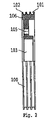
- FIG. 2 presents a rope pulley applying the invention
- FIGS. 3 and 4 present the rope groove of a traction sheave according to the invention.
- FIG. 1 is a diagrammatic representation of the structure of an elevator.
- the elevator is preferably an elevator without machine room, with a drive machine 6 placed in the elevator shaft, although the invention is also applicable for use in elevators having a machine room.
- the hoisting ropes 3 of the elevator run as follows: One end of the rope set is immovably fixed to an anchorage 13 in the upper part of the shaft above the track of the counterweight 2 moving along counterweight guide rails 11 , from where the ropes go downwards to diverting pulleys 9 suspending the counterweight and rotatably connected to the counterweight 2 , and from these diverting pulleys 9 the ropes 3 go further upwards to the traction sheave 7 of the drive machine 6 , running over the traction sheave along rope grooves provided in it.
- Anchorage 13 in the upper part of the shaft, the traction sheave 7 and the diverting pulley 9 suspending the counterweight on the ropes are preferably so disposed in relation to each other that both the rope portion going from the anchorage 13 to the counterweight 2 and the rope portion going from the counterweight 2 to the traction sheave 7 are substantially parallel to the path of the counterweight 2 .
- anchorage 14 in the upper part of the shaft, the traction sheave 7 and the diverting pulleys 4 suspending the elevator car on the ropes are so disposed in relation to each other that the rope portion going from the anchorage 14 to the elevator car 1 and the rope portion going from the elevator car 1 to the traction sheave 7 are substantially parallel to the path of the elevator car 1 .
- the rope suspension acts in a substantially centric manner on the elevator car 1 , provided that the rope pulleys 4 supporting the elevator car are mounted substantially symmetrically relative to the vertical center line passing via the center of gravity of the elevator car 1 .
- the drive machine 6 preferably placed in the elevator shaft, is of a flat construction, in other words, the machine has a small depth as compared with its width and/or height, or at least the machine is slim enough to be accommodated between the elevator car and a wall of the elevator shaft.
- the machine may also be placed differently. Especially a slim machine can be fairly easily mounted above the elevator car.
- the elevator shaft it is preferable to place equipment required for the supply of power to the motor driving the traction sheave 7 as well as equipment for elevator control, both of which can be placed in a common instrument panel 8 or mounted separately from each other or integrated partly or wholly with the drive machine 6 .
- the drive machine may be of a geared or a gearless type.
- a preferable solution is a gearless machine comprising a permanent-magnet motor.
- the drive machine may be fixed to a wall of the elevator shaft, to the ceiling, to a guide rail or guide rails or to some other structure, such as a beam or frame.
- a further possibility is to mount the machine on the bottom of the elevator shaft.
- FIG. 1 illustrates the economical 2:1 suspension, but the invention can also be implemented in an elevator using a 1:1 suspension ratio, in other words, in an elevator in which the hoisting ropes are connected directly to the counterweight and elevator car without diverting pulleys, or in an elevator implemented using some other suspension arrangement suited for a traction sheave elevator.
- FIG. 2 presents a partially sectioned view of a rope pulley applying the invention.
- the rope grooves 101 on the outer rim 106 of the rope pulley are covered by a coating 102 .
- the hub of the rope pulley contains a space 103 for a bearing used to mount the rope pulley.
- the rope pulley is also provided with holes 105 for bolts, allowing the rope pulley to be fastened by its side to an anchorage in the hoisting machine 6 , e.g. to a rotating flange, to form a traction sheave 7 , in which case no bearing separate from the hoisting machine is needed.
- the material of a rope pulley used as a traction sheave so chosen that it forms a material pair with the hoisting rope used, such that the hoisting rope 3 will bite into the rope groove 101 after the coating 102 has been lost. This ensures a sufficient grip between the rope pulley 100 and the hoisting rope 3 in an emergency where the coating 102 of the rope pulley 100 has been lost. This feature allows the elevator to maintain its functionality and operational reliability in the situation referred to.
- the traction sheave can also be manufactured in such manner that only the outer rim 106 of the rope pulley 100 used as a traction sheave is made of a material that forms a grip increasing material pair with the hoisting rope 3 .
- FIG. 3 presents a cross-sectional view of a rope groove to illustrate a structural solution designed to improve the grip after the coating has been lost or worn out.
- the bottom of the rope groove 201 under the coating 202 in the groove has a groove shape 203 that allows the rope to bite more effectively into the groove.
- the groove shape 203 or equivalent allows the rope to bite more firmly into the rope pulley, thereby ensuring a sufficient grip between the hoisting rope 3 and the rope pulley 100 used as traction sheave while at the same time protecting the hoisting rope against damage in connection with the contact.
- the groove shape allowing the rope to bite more effectively into the groove may consist of an undercut groove, a V-shaped groove or a similar groove shape. It may also consist of a number of parallel grooves of different shapes under the coating 202 at the bottom of the rope groove 201 , ensuring that the hoisting rope 3 will bite into the rope pulley 100 after the coating 202 has been lost and the grip weakened.
- FIG. 4 presents a rope pulley 100 used as a traction sheave and having a coating 202 in a rope groove 201 in which an insert 204 made of a different material has been added under the coating to enhance the bite-in effect.
- an insert 204 made of a different material has been added under the coating to enhance the bite-in effect.
- the use of an insert makes it unnecessary to form a material pair enhancing the bite-in effect between the hoisting rope and the material of the entire rope pulley 100 ; instead, it is only necessary to add an insert forming such a material pair.
- the insert material used may be soft steel, cast iron, brass or some other metal or equivalent material appropriate for this purpose.
- the insert 204 added on the bottom of the rope groove 201 under the coating 202 may also consist of a tube or a half-tube going around the entire rope pulley 100 along the bottom of the rope groove 201 .
- the material of at least the rope pulley 100 used as a traction sheave forms together with the hoisting rope 3 used a material pair in which the rope 3 bites into the rope pulley 100 .
- the temporary reduction of friction between the rope pulley 100 and the hoisting rope 3 occurring after a loss of the coating 102 before the rope 3 starts biting into the rope pulley 100 can be diminished by grooves 203 of different shapes made in the bottom of the rope groove 201 . With this arrangement, a faster and more secure grip between the rope pulley 100 and the hoisting rope 3 is achieved.
- the coating material 202 used in the rope groove 201 may consist of rubber, polyurethane or some other elastic material.
- the use of a coating 202 makes it possible to achieve a large friction between the rope pulley 100 and the hoisting rope 3 as well as a uniform support for the hoisting rope 3 , reducing the strain of the interior parts of the rope.
- the coating 202 disappears from the surface of the rope pulley 100
- the material pair selected and the eventual auxiliary grooving 203 at the bottom of the rope groove 201 can provide a sufficient coefficient of friction quickly and reliably between the hoisting rope 3 and the rope pulley 100 . This makes it possible to reach a surety regarding the operation and safety of the elevator about the functionality of the elevator in a problem situation.
- the rope pulley 100 can be manufactured from soft steel, cast iron, aluminum, brass or some other metal or equivalent material suited for the purpose and having properties that make it applicable for use as a material in the rope pulley 100 and allowing the hoisting rope 3 to bite into the material, thereby producing a grip sufficient for the operation of the elevator as well as an effect protecting the hoisting rope against damage in a situation where the coating material 202 on the surface of the rope pulley 100 has been lost.
- a sufficient grip between the traction sheave 100 and the hoisting rope 3 in exceptional conditions where the coating 202 has been lost can also be implemented by providing a roughened area on the bottom of the rope groove 201 on the surface of the traction sheave material under the coating 202 , said roughened area producing a friction between the hoisting rope 3 and the rope pulley 100 that is sufficient for the operation of the elevator.
Applications Claiming Priority (3)
| Application Number | Priority Date | Filing Date | Title |
|---|---|---|---|
| FI20010555A FI109897B (fi) | 2001-03-19 | 2001-03-19 | Hissi ja hissin vetopyörä |
| FIFI20010555 | 2001-03-19 | ||
| PCT/FI2002/000153 WO2002074677A2 (fr) | 2001-03-19 | 2002-02-25 | Ascenseur et poulie d'entrainement d'un ascenseur |
Related Parent Applications (1)
| Application Number | Title | Priority Date | Filing Date |
|---|---|---|---|
| PCT/FI2002/000153 Continuation WO2002074677A2 (fr) | 2001-03-19 | 2002-02-25 | Ascenseur et poulie d'entrainement d'un ascenseur |
Publications (2)
| Publication Number | Publication Date |
|---|---|
| US20040065513A1 US20040065513A1 (en) | 2004-04-08 |
| US7461721B2 true US7461721B2 (en) | 2008-12-09 |
Family
ID=8560782
Family Applications (1)
| Application Number | Title | Priority Date | Filing Date |
|---|---|---|---|
| US10/665,532 Expired - Fee Related US7461721B2 (en) | 2001-03-19 | 2003-09-22 | Elevator and traction sheave of an elevator |
Country Status (10)
| Country | Link |
|---|---|
| US (1) | US7461721B2 (fr) |
| EP (1) | EP1385770A2 (fr) |
| JP (1) | JP4913314B2 (fr) |
| KR (1) | KR100916769B1 (fr) |
| CN (1) | CN1269718C (fr) |
| AU (1) | AU2002237333A1 (fr) |
| BR (1) | BR0208264B1 (fr) |
| FI (1) | FI109897B (fr) |
| HK (1) | HK1066519A1 (fr) |
| WO (1) | WO2002074677A2 (fr) |
Cited By (8)
| Publication number | Priority date | Publication date | Assignee | Title |
|---|---|---|---|---|
| US20040129501A1 (en) * | 2001-01-04 | 2004-07-08 | Horst Wittur | Gearless cable lift with a dual wind drive disk mechanism |
| US20110108785A1 (en) * | 2002-03-08 | 2011-05-12 | Peter Graebner | Drive disk for high performance friction pairings |
| US8430210B2 (en) | 2011-01-19 | 2013-04-30 | Smart Lifts, Llc | System having multiple cabs in an elevator shaft |
| US8925689B2 (en) | 2011-01-19 | 2015-01-06 | Smart Lifts, Llc | System having a plurality of elevator cabs and counterweights that move independently in different sections of a hoistway |
| US9365392B2 (en) | 2011-01-19 | 2016-06-14 | Smart Lifts, Llc | System having multiple cabs in an elevator shaft and control method thereof |
| US10377605B2 (en) * | 2015-08-12 | 2019-08-13 | Kone Corporation | Rope and rope groove monitoring |
| US10493518B2 (en) | 2016-08-30 | 2019-12-03 | Otis Elevator Company | Sheave knurling tool and method of operating |
| US20200055707A1 (en) * | 2018-08-17 | 2020-02-20 | Otis Elevator Company | Friction liner and traction sheave |
Families Citing this family (22)
| Publication number | Priority date | Publication date | Assignee | Title |
|---|---|---|---|---|
| FI118732B (fi) | 2000-12-08 | 2008-02-29 | Kone Corp | Hissi |
| DK1397304T3 (da) | 2001-06-21 | 2008-08-04 | Kone Corp | Elevator |
| US9573792B2 (en) | 2001-06-21 | 2017-02-21 | Kone Corporation | Elevator |
| FI119234B (fi) * | 2002-01-09 | 2008-09-15 | Kone Corp | Hissi |
| FI119236B (fi) * | 2002-06-07 | 2008-09-15 | Kone Corp | Päällystetyllä nostoköydellä varustettu hissi |
| JP4683863B2 (ja) * | 2003-06-19 | 2011-05-18 | インベンテイオ・アクテイエンゲゼルシヤフト | 可動式牽引手段による負荷輸送用の昇降機 |
| US8172041B2 (en) | 2004-06-01 | 2012-05-08 | Toshiba Elevator Kabushiki Kaisha | Machine room-less elevator |
| WO2008112537A2 (fr) * | 2007-03-15 | 2008-09-18 | Hugh O'donnell | Élément porteur de charge flexible pour système d'élévateur |
| JP5060567B2 (ja) * | 2010-01-22 | 2012-10-31 | 株式会社日立製作所 | エレベーターのロープ巻き掛け方法、及び部材 |
| CN102556881A (zh) * | 2012-01-18 | 2012-07-11 | 兰州富川机电设备有限公司 | 一种新型曳引机制动装置 |
| JP2015037990A (ja) * | 2013-06-14 | 2015-02-26 | 東芝エレベータ株式会社 | エレベータ装置 |
| CN103771251B (zh) * | 2013-12-19 | 2016-06-08 | 柳州正菱集团有限公司 | 便携式机床安装用起吊设备 |
| CN103738827A (zh) * | 2013-12-19 | 2014-04-23 | 柳州正菱集团有限公司 | 吊装工具 |
| CN103738828A (zh) * | 2013-12-19 | 2014-04-23 | 柳州正菱集团有限公司 | 一种便携式机床安装用起吊设备 |
| US10486942B2 (en) | 2014-05-16 | 2019-11-26 | Inventio Ag | Elevator installation roller with restraining element |
| WO2017162749A1 (fr) | 2016-03-23 | 2017-09-28 | Inventio Ag | Installation d'ascenseur dotée d'un élément de suspension entouré en partie d'un boîtier électroconducteur, en particulier sur un ensemble poulie de renvoi |
| US11111108B2 (en) * | 2018-05-04 | 2021-09-07 | Otis Elevator Company | Coated sheave |
| CN110356910B (zh) * | 2019-08-16 | 2024-03-08 | 国网江苏省电力有限公司扬州供电分公司 | 一种集中式布线器 |
| US11511970B2 (en) * | 2020-08-01 | 2022-11-29 | Otis Elevator Company | High friction and wear resistant elevator sheave liner |
| CN113102198B (zh) * | 2021-03-12 | 2022-11-25 | 中国联合工程有限公司 | 一种用于车辆零部件面漆和套色工艺的组合式烘干系统 |
| CN113844995A (zh) * | 2021-09-30 | 2021-12-28 | 中国石油大学(华东) | 一种钢丝绳啮合传动轮及其制造方法 |
| CN114086789B (zh) * | 2021-11-29 | 2023-02-03 | 鹏盛建设集团有限公司 | 一种建筑施工用建筑构件的防坠装置 |
Citations (12)
| Publication number | Priority date | Publication date | Assignee | Title |
|---|---|---|---|---|
| US3279762A (en) * | 1964-03-11 | 1966-10-18 | Otis Elevator Co | Noise abating and traction improving elevator sheave |
| US4030569A (en) * | 1975-10-07 | 1977-06-21 | Westinghouse Electric Corporation | Traction elevator system having cable groove in drive sheave formed by spaced, elastically deflectable metallic ring members |
| JPS54104145A (en) | 1978-02-03 | 1979-08-16 | Hitachi Ltd | Driving device of elevator |
| JPS57114061A (en) | 1981-01-07 | 1982-07-15 | Hitachi Ltd | Driving sheave |
| JPS59102787A (ja) | 1983-11-18 | 1984-06-13 | 株式会社東芝 | エレベ−タのトラクシヨンシ−ブ |
| US4465161A (en) | 1981-02-17 | 1984-08-14 | Mitsubishi Denki Kabushiki Kaisha | Elevator winding device |
| JPS59164450A (ja) * | 1983-03-04 | 1984-09-17 | Toshiba Corp | エレベ−タのトラクシヨンシ−ブ |
| SU1641759A1 (ru) * | 1988-03-09 | 1991-04-15 | Научно-производственное объединение по механизации, роботизации труда и совершенствованию ремонтного обеспечения на предприятиях черной металлургии "Черметмеханизация" | Направл ющий шкив |
| JPH08277082A (ja) | 1995-04-10 | 1996-10-22 | Hitachi Ltd | エレベータ駆動装置及びエレベータ |
| JPH11325200A (ja) | 1998-05-15 | 1999-11-26 | Kenji Ito | ロープ巻掛け伝動装置 |
| US6267205B1 (en) * | 2000-04-18 | 2001-07-31 | Otis Elevator Company | Magnetic guidance for an elevator rope |
| US6371448B1 (en) * | 1999-10-29 | 2002-04-16 | Inventio Ag | Rope drive element for driving synthetic fiber ropes |
Family Cites Families (3)
| Publication number | Priority date | Publication date | Assignee | Title |
|---|---|---|---|---|
| JPS56128387U (fr) * | 1980-02-28 | 1981-09-30 | ||
| JPS60145170U (ja) * | 1984-03-05 | 1985-09-26 | 株式会社東芝 | エレベ−タのトラクシヨンシ−ブ |
| JPS61169479A (ja) * | 1985-01-23 | 1986-07-31 | 三菱電機株式会社 | トラクシヨン式エレベ−タ装置 |
-
2001
- 2001-03-19 FI FI20010555A patent/FI109897B/fi not_active IP Right Cessation
-
2002
- 2002-02-25 WO PCT/FI2002/000153 patent/WO2002074677A2/fr active Application Filing
- 2002-02-25 EP EP02703639A patent/EP1385770A2/fr not_active Withdrawn
- 2002-02-25 BR BRPI0208264-0A patent/BR0208264B1/pt not_active IP Right Cessation
- 2002-02-25 CN CNB028068734A patent/CN1269718C/zh not_active Expired - Fee Related
- 2002-02-25 JP JP2002573347A patent/JP4913314B2/ja not_active Expired - Fee Related
- 2002-02-25 KR KR1020037012205A patent/KR100916769B1/ko not_active IP Right Cessation
- 2002-02-25 AU AU2002237333A patent/AU2002237333A1/en not_active Abandoned
-
2003
- 2003-09-22 US US10/665,532 patent/US7461721B2/en not_active Expired - Fee Related
-
2004
- 2004-11-30 HK HK04109448A patent/HK1066519A1/xx not_active IP Right Cessation
Patent Citations (12)
| Publication number | Priority date | Publication date | Assignee | Title |
|---|---|---|---|---|
| US3279762A (en) * | 1964-03-11 | 1966-10-18 | Otis Elevator Co | Noise abating and traction improving elevator sheave |
| US4030569A (en) * | 1975-10-07 | 1977-06-21 | Westinghouse Electric Corporation | Traction elevator system having cable groove in drive sheave formed by spaced, elastically deflectable metallic ring members |
| JPS54104145A (en) | 1978-02-03 | 1979-08-16 | Hitachi Ltd | Driving device of elevator |
| JPS57114061A (en) | 1981-01-07 | 1982-07-15 | Hitachi Ltd | Driving sheave |
| US4465161A (en) | 1981-02-17 | 1984-08-14 | Mitsubishi Denki Kabushiki Kaisha | Elevator winding device |
| JPS59164450A (ja) * | 1983-03-04 | 1984-09-17 | Toshiba Corp | エレベ−タのトラクシヨンシ−ブ |
| JPS59102787A (ja) | 1983-11-18 | 1984-06-13 | 株式会社東芝 | エレベ−タのトラクシヨンシ−ブ |
| SU1641759A1 (ru) * | 1988-03-09 | 1991-04-15 | Научно-производственное объединение по механизации, роботизации труда и совершенствованию ремонтного обеспечения на предприятиях черной металлургии "Черметмеханизация" | Направл ющий шкив |
| JPH08277082A (ja) | 1995-04-10 | 1996-10-22 | Hitachi Ltd | エレベータ駆動装置及びエレベータ |
| JPH11325200A (ja) | 1998-05-15 | 1999-11-26 | Kenji Ito | ロープ巻掛け伝動装置 |
| US6371448B1 (en) * | 1999-10-29 | 2002-04-16 | Inventio Ag | Rope drive element for driving synthetic fiber ropes |
| US6267205B1 (en) * | 2000-04-18 | 2001-07-31 | Otis Elevator Company | Magnetic guidance for an elevator rope |
Non-Patent Citations (4)
| Title |
|---|
| Patent Abstracts of Japan, vol. 003, No. 126 (Oct. 20, 1979) & JP 54 104145 A (Aug. 16, 1979). |
| Patent Abstracts of Japan, vol. 006, No. 207 (Oct. 19, 1982) & JP 57 114061 A (Jul. 15, 1982). |
| Patent Abstracts of Japan, vol. 1997, No. 02 (Feb. 28, 1997) & JP 08 277082 A (Oct. 22, 1996). |
| Patent Abstracts of Japan, vol. 2000, No. 02 (Feb. 29, 2000) & JP 11 325200 A (Nov. 26, 1999). |
Cited By (15)
| Publication number | Priority date | Publication date | Assignee | Title |
|---|---|---|---|---|
| US20040129501A1 (en) * | 2001-01-04 | 2004-07-08 | Horst Wittur | Gearless cable lift with a dual wind drive disk mechanism |
| US20110108785A1 (en) * | 2002-03-08 | 2011-05-12 | Peter Graebner | Drive disk for high performance friction pairings |
| US8132789B2 (en) * | 2002-03-08 | 2012-03-13 | Peter Graebner | Drive disk for high performance friction pairings |
| US8925689B2 (en) | 2011-01-19 | 2015-01-06 | Smart Lifts, Llc | System having a plurality of elevator cabs and counterweights that move independently in different sections of a hoistway |
| US20140367204A1 (en) * | 2011-01-19 | 2014-12-18 | Smart Lifts, Llc | System Having Multiple Cabs in an Elevator Shaft |
| US8919501B2 (en) | 2011-01-19 | 2014-12-30 | Smart Lifts, Llc | System having multiple cabs in an elevator shaft |
| US8430210B2 (en) | 2011-01-19 | 2013-04-30 | Smart Lifts, Llc | System having multiple cabs in an elevator shaft |
| US9365392B2 (en) | 2011-01-19 | 2016-06-14 | Smart Lifts, Llc | System having multiple cabs in an elevator shaft and control method thereof |
| US9481550B2 (en) * | 2011-01-19 | 2016-11-01 | Smart Lifts, Llc | System having multiple cabs in an elevator shaft |
| US10377605B2 (en) * | 2015-08-12 | 2019-08-13 | Kone Corporation | Rope and rope groove monitoring |
| US10493518B2 (en) | 2016-08-30 | 2019-12-03 | Otis Elevator Company | Sheave knurling tool and method of operating |
| US11344944B2 (en) | 2016-08-30 | 2022-05-31 | Otis Elevator Company | Sheave knurling tool and method of operating |
| US20200055707A1 (en) * | 2018-08-17 | 2020-02-20 | Otis Elevator Company | Friction liner and traction sheave |
| US10766746B2 (en) * | 2018-08-17 | 2020-09-08 | Otis Elevator Company | Friction liner and traction sheave |
| US11254544B2 (en) | 2018-08-17 | 2022-02-22 | Otis Elevator Company | Friction liner and traction sheave |
Also Published As
| Publication number | Publication date |
|---|---|
| JP2004523445A (ja) | 2004-08-05 |
| EP1385770A2 (fr) | 2004-02-04 |
| JP4913314B2 (ja) | 2012-04-11 |
| HK1066519A1 (en) | 2005-03-24 |
| FI109897B (fi) | 2002-10-31 |
| KR20030081529A (ko) | 2003-10-17 |
| BR0208264A (pt) | 2004-03-02 |
| CN1518520A (zh) | 2004-08-04 |
| WO2002074677A3 (fr) | 2003-05-30 |
| WO2002074677A2 (fr) | 2002-09-26 |
| AU2002237333A1 (en) | 2002-10-03 |
| US20040065513A1 (en) | 2004-04-08 |
| FI20010555A0 (fi) | 2001-03-19 |
| KR100916769B1 (ko) | 2009-09-14 |
| BR0208264B1 (pt) | 2012-06-26 |
| CN1269718C (zh) | 2006-08-16 |
Similar Documents
| Publication | Publication Date | Title |
|---|---|---|
| US7461721B2 (en) | Elevator and traction sheave of an elevator | |
| RU2302368C2 (ru) | Лифт и канатоведущий шкив лифта | |
| RU2492130C2 (ru) | Тонкая высокопрочная проволока для подъемного каната лифта | |
| JP2004523445A5 (fr) | ||
| RU2352514C2 (ru) | Лифт | |
| CA2500819A1 (fr) | Elevateur | |
| RU2317937C2 (ru) | Лифт, канатоведущий шкив лифта и покрытие для канатных канавок канатоведущего шкива лифта | |
| EP1327599B1 (fr) | Dispositif elevateur | |
| EP1701906B1 (fr) | Ascenseur | |
| CN100540441C (zh) | 电梯 |
Legal Events
| Date | Code | Title | Description |
|---|---|---|---|
| AS | Assignment |
Owner name: KONE CORPORATION, FINLAND Free format text: ASSIGNMENT OF ASSIGNORS INTEREST;ASSIGNORS:AULANKO, ESKO;MUSTALAHTI, JORMA;REEL/FRAME:014721/0246 Effective date: 20031022 |
|
| STCF | Information on status: patent grant |
Free format text: PATENTED CASE |
|
| FEPP | Fee payment procedure |
Free format text: PAYOR NUMBER ASSIGNED (ORIGINAL EVENT CODE: ASPN); ENTITY STATUS OF PATENT OWNER: LARGE ENTITY |
|
| FPAY | Fee payment |
Year of fee payment: 4 |
|
| FPAY | Fee payment |
Year of fee payment: 8 |
|
| FEPP | Fee payment procedure |
Free format text: MAINTENANCE FEE REMINDER MAILED (ORIGINAL EVENT CODE: REM.); ENTITY STATUS OF PATENT OWNER: LARGE ENTITY |
|
| LAPS | Lapse for failure to pay maintenance fees |
Free format text: PATENT EXPIRED FOR FAILURE TO PAY MAINTENANCE FEES (ORIGINAL EVENT CODE: EXP.); ENTITY STATUS OF PATENT OWNER: LARGE ENTITY |
|
| STCH | Information on status: patent discontinuation |
Free format text: PATENT EXPIRED DUE TO NONPAYMENT OF MAINTENANCE FEES UNDER 37 CFR 1.362 |
|
| FP | Lapsed due to failure to pay maintenance fee |
Effective date: 20201209 |