US7240398B2 - Opening and closing damping apparatus - Google Patents
Opening and closing damping apparatus Download PDFInfo
- Publication number
- US7240398B2 US7240398B2 US10/924,259 US92425904A US7240398B2 US 7240398 B2 US7240398 B2 US 7240398B2 US 92425904 A US92425904 A US 92425904A US 7240398 B2 US7240398 B2 US 7240398B2
- Authority
- US
- United States
- Prior art keywords
- annular groove
- rotor
- elastic
- annulus
- elastic protrusion
- Prior art date
- Legal status (The legal status is an assumption and is not a legal conclusion. Google has not performed a legal analysis and makes no representation as to the accuracy of the status listed.)
- Expired - Lifetime
Links
- 238000013016 damping Methods 0.000 title claims description 29
- 238000007789 sealing Methods 0.000 claims description 9
- 239000011345 viscous material Substances 0.000 claims 8
- 239000004519 grease Substances 0.000 abstract description 39
- 239000012530 fluid Substances 0.000 abstract description 7
- 230000001105 regulatory effect Effects 0.000 abstract description 6
- 230000007246 mechanism Effects 0.000 description 21
- 230000000694 effects Effects 0.000 description 3
- 238000003780 insertion Methods 0.000 description 3
- 230000037431 insertion Effects 0.000 description 3
- 230000014759 maintenance of location Effects 0.000 description 3
- 230000006835 compression Effects 0.000 description 1
- 238000007906 compression Methods 0.000 description 1
- -1 for example Substances 0.000 description 1
- 238000004519 manufacturing process Methods 0.000 description 1
- 239000000463 material Substances 0.000 description 1
- 238000000034 method Methods 0.000 description 1
- 239000004745 nonwoven fabric Substances 0.000 description 1
- 230000000717 retained effect Effects 0.000 description 1
Images


Classifications
-
- F—MECHANICAL ENGINEERING; LIGHTING; HEATING; WEAPONS; BLASTING
- F16—ENGINEERING ELEMENTS AND UNITS; GENERAL MEASURES FOR PRODUCING AND MAINTAINING EFFECTIVE FUNCTIONING OF MACHINES OR INSTALLATIONS; THERMAL INSULATION IN GENERAL
- F16C—SHAFTS; FLEXIBLE SHAFTS; ELEMENTS OR CRANKSHAFT MECHANISMS; ROTARY BODIES OTHER THAN GEARING ELEMENTS; BEARINGS
- F16C11/00—Pivots; Pivotal connections
- F16C11/04—Pivotal connections
-
- E—FIXED CONSTRUCTIONS
- E05—LOCKS; KEYS; WINDOW OR DOOR FITTINGS; SAFES
- E05F—DEVICES FOR MOVING WINGS INTO OPEN OR CLOSED POSITION; CHECKS FOR WINGS; WING FITTINGS NOT OTHERWISE PROVIDED FOR, CONCERNED WITH THE FUNCTIONING OF THE WING
- E05F3/00—Closers or openers with braking devices, e.g. checks; Construction of pneumatic or liquid braking devices
- E05F3/14—Closers or openers with braking devices, e.g. checks; Construction of pneumatic or liquid braking devices with fluid brakes of the rotary type
-
- B—PERFORMING OPERATIONS; TRANSPORTING
- B60—VEHICLES IN GENERAL
- B60R—VEHICLES, VEHICLE FITTINGS, OR VEHICLE PARTS, NOT OTHERWISE PROVIDED FOR
- B60R7/00—Stowing or holding appliances inside vehicle primarily intended for personal property smaller than suit-cases, e.g. travelling articles, or maps
- B60R7/04—Stowing or holding appliances inside vehicle primarily intended for personal property smaller than suit-cases, e.g. travelling articles, or maps in driver or passenger space, e.g. using racks
- B60R7/06—Stowing or holding appliances inside vehicle primarily intended for personal property smaller than suit-cases, e.g. travelling articles, or maps in driver or passenger space, e.g. using racks mounted on or below dashboards
-
- B—PERFORMING OPERATIONS; TRANSPORTING
- B60—VEHICLES IN GENERAL
- B60R—VEHICLES, VEHICLE FITTINGS, OR VEHICLE PARTS, NOT OTHERWISE PROVIDED FOR
- B60R7/00—Stowing or holding appliances inside vehicle primarily intended for personal property smaller than suit-cases, e.g. travelling articles, or maps
- B60R7/08—Disposition of racks, clips, holders, containers or the like for supporting specific articles
- B60R7/10—Disposition of racks, clips, holders, containers or the like for supporting specific articles for supporting hats, clothes or clothes hangers
-
- E—FIXED CONSTRUCTIONS
- E05—LOCKS; KEYS; WINDOW OR DOOR FITTINGS; SAFES
- E05Y—INDEXING SCHEME ASSOCIATED WITH SUBCLASSES E05D AND E05F, RELATING TO CONSTRUCTION ELEMENTS, ELECTRIC CONTROL, POWER SUPPLY, POWER SIGNAL OR TRANSMISSION, USER INTERFACES, MOUNTING OR COUPLING, DETAILS, ACCESSORIES, AUXILIARY OPERATIONS NOT OTHERWISE PROVIDED FOR, APPLICATION THEREOF
- E05Y2201/00—Constructional elements; Accessories therefor
- E05Y2201/20—Brakes; Disengaging means; Holders; Stops; Valves; Accessories therefor
- E05Y2201/21—Brakes
-
- E—FIXED CONSTRUCTIONS
- E05—LOCKS; KEYS; WINDOW OR DOOR FITTINGS; SAFES
- E05Y—INDEXING SCHEME ASSOCIATED WITH SUBCLASSES E05D AND E05F, RELATING TO CONSTRUCTION ELEMENTS, ELECTRIC CONTROL, POWER SUPPLY, POWER SIGNAL OR TRANSMISSION, USER INTERFACES, MOUNTING OR COUPLING, DETAILS, ACCESSORIES, AUXILIARY OPERATIONS NOT OTHERWISE PROVIDED FOR, APPLICATION THEREOF
- E05Y2201/00—Constructional elements; Accessories therefor
- E05Y2201/20—Brakes; Disengaging means; Holders; Stops; Valves; Accessories therefor
- E05Y2201/252—Type of friction
- E05Y2201/254—Fluid or viscous friction
-
- E—FIXED CONSTRUCTIONS
- E05—LOCKS; KEYS; WINDOW OR DOOR FITTINGS; SAFES
- E05Y—INDEXING SCHEME ASSOCIATED WITH SUBCLASSES E05D AND E05F, RELATING TO CONSTRUCTION ELEMENTS, ELECTRIC CONTROL, POWER SUPPLY, POWER SIGNAL OR TRANSMISSION, USER INTERFACES, MOUNTING OR COUPLING, DETAILS, ACCESSORIES, AUXILIARY OPERATIONS NOT OTHERWISE PROVIDED FOR, APPLICATION THEREOF
- E05Y2201/00—Constructional elements; Accessories therefor
- E05Y2201/20—Brakes; Disengaging means; Holders; Stops; Valves; Accessories therefor
- E05Y2201/262—Type of motion, e.g. braking
- E05Y2201/266—Type of motion, e.g. braking rotary
-
- E—FIXED CONSTRUCTIONS
- E05—LOCKS; KEYS; WINDOW OR DOOR FITTINGS; SAFES
- E05Y—INDEXING SCHEME ASSOCIATED WITH SUBCLASSES E05D AND E05F, RELATING TO CONSTRUCTION ELEMENTS, ELECTRIC CONTROL, POWER SUPPLY, POWER SIGNAL OR TRANSMISSION, USER INTERFACES, MOUNTING OR COUPLING, DETAILS, ACCESSORIES, AUXILIARY OPERATIONS NOT OTHERWISE PROVIDED FOR, APPLICATION THEREOF
- E05Y2900/00—Application of doors, windows, wings or fittings thereof
- E05Y2900/50—Application of doors, windows, wings or fittings thereof for vehicles
- E05Y2900/53—Type of wing
- E05Y2900/538—Interior lids
Definitions
- the present invention relates to an opening and closing damping apparatus for slowly opening and closing a rotation body.
- structure bodies having various opening and closing mechanisms are provided in the vehicle interior of a vehicle such as an automobile.
- the structure bodies include a retractable hook apparatus, a retractable assist grip apparatus, a retractable storage box, a cup holder, a glove box, a console box, etc.
- an opening and closing damping mechanism which has a shaft part for supporting a rotation member, a support body for rotatably supporting the shaft part and a spring for always energizing the rotation member in an opening direction or a closing direction, and further slowly opens and closes the rotation member against energization force of the spring.
- a grease damper constructed so that there are provided a cylindrical support body and a columnar shaft body which is inserted into this support body and also is integrated with an opening and closing body and a grease passage and a grease retention are formed in the shaft body and grease with a predetermined viscosity is injected between the shaft body and an inner circumference of the support body and thereby the grease is retained in the grease passage and the grease retention and the opening and closing body is slowly rotated by the viscosity of this grease is disclosed in, for example, JP-A-10-54171.
- a rotary damper constructed so that grease or oil is not used as a member for damping opening and closing of an opening and closing body integrally provided in a shaft body and the opening and closing body is slowly rotated by friction sliding between a support body and the shaft body is disclosed in JP-A-2002-193012.
- the support body for rotatably supporting the shaft body is required, so that there is a problem that assembly and manufacture of the support body become complicated and product cost increases. Further, since the shaft body is used as a component of the damper, applied material is limited in the case of use in a place in which rigidity is required, so that there is a problem that it is lacking in versatility.
- An object of the invention is to provide an opening and closing damping apparatus in which a shaft body is not used as a component of a damper and also in the case of use in a place in which rigidity is required, a large load is not applied to the shaft body and use in a wide range is enabled and also durability is good.
- an opening and closing damping apparatus for applying damping to rotation of a rotation body pivoted openably and closably with respect to a support body, an engagement part is provided in one of the support body and the rotation body and an annular groove part with the bottom is provided on the same axis as the center of rotation of the other, and a substantially cylindrical rotor is fitted into the annular groove part with the bottom, and an engagement stop part engaged and stopped in the engagement part is provided in the end of the rotor, and a viscous member is interposed between the rotor and the annular groove part with the bottom.
- an engagement stop part provided in the end of a rotor formed in substantially cylindrical shape is engaged in an engagement part provided in one of a support body and a rotation body and the is fitted into an annular groove part with the bottom provided in the other of the support body and the rotation body and also a viscous member is interposed between the rotor and the annular groove part with the bottom and the rotation body is slowly rotated by fluid resistance of the viscous member, so that a large load is not applied to a shaft body for supporting the support body and the rotation body on the same axis and use in a wide range is enabled and also durability is good.
- a first elastic annulus and a second elastic annulus are respectively provided in an outer circumference and an inner circumference of the rotor, and a first elastic protrusion elongated annulus and a second elastic protrusion elongated annulus for respectively abutting on a wall surface of the annular groove part with the bottom and sealing the viscous member are respectively provided in each of the elastic annuli.
- the first elastic annulus is provided in the bottom side of the annular groove part with the bottom from the second elastic annulus.
- wall thickness of a rotor can be reduced to achieve miniaturization by offsetting axial arrangement of both the elastic annuli.
- an air relief groove is provided between the end of the bottom side of the annular groove part with the bottom and the first elastic annulus and/or the second elastic annulus of the rotor.
- the fourth aspect of the invention in the case of inserting a rotor into an annular groove part with the bottom after a viscous member is charged into the annular groove part with the bottom, air remaining inside the annular groove part with the bottom can be released to an air relief groove, so that this air is not compressed more than necessary and a burst of the rotor and leakage of the viscous member can be prevented.
- the first elastic annulus and the second elastic annulus are provided at a substantially equal distance from the bottom of the annular groove part with the bottom, and the air relief groove is formed continuously in the range from the end of the bottom side of the annular groove part with the bottom to at least one of the first elastic annulus and the second elastic annulus.
- a region in which a viscous member is charged and abuts slidingly is formed long in an axial direction and a damper effect can be increased and also the air relief groove is formed continuously in the range from the end of the bottom side of the annular groove part with the bottom to at least one of the first elastic annulus and the second elastic annulus, so that air can be released until a rotor is substantially fully inserted into the annular groove part with the bottom, and leakage of the viscous member and a burst of the rotor due to compression of air sealed can be prevented more surely.
- the engagement part is constructed of two protrusion elongated parts protruded in parallel and the engagement stop part is formed in protrusion shape engaged between both of said protrusion elongated parts.
- assembly is completed by only fitting a protrusive engagement stop part provided in the end of a rotor between two protrusion elongated parts formed in one of a support body and a rotation body, so that assembly is facilitated. Further, a slidingly abutting region between the rotor and a viscous member can be provided long in an axial direction by providing the engagement stop part in the end of the rotor, so that utilization of a region for producing damping effect can be maximized.
- an engagement stop part provided in the end of a rotor formed in substantially cylindrical shape is engaged in an engagement part provided in one of a support body and a rotation body and the is fitted into an annular groove part with the bottom provided in the other of the support body and the rotation body and also a viscous member is interposed between the rotor and the annular groove part with the bottom and the rotation body is slowly rotated by fluid resistance of the viscous member, so that there can be provided an opening and closing damping apparatus in which a large load is not applied to a shaft body for supporting the support body and the rotation body on the same axis and use in a wide range is enabled and also durability is good.
- FIG. 1 is an exploded perspective view of a retractable hook apparatus according to a first embodiment
- FIG. 2A is a perspective view seen from the front of the retractable hook apparatus and FIG. 2B is a perspective view seen from the back of the retractable hook apparatus in the first embodiment;
- FIG. 3A is a front view of a retracting case and FIG. 3B is a side view of the retracting case and FIG. 3C is a sectional view taken on line C—C of FIG. 3A in the first embodiment;
- FIG. 4A is a front view of a hook and FIG. 4B is a sectional view taken on line B—B of FIG. 4A in the first embodiment;
- FIG. 5 is a front view of a swing cam in the first embodiment
- FIG. 6A is a front view of a decorative plate and FIG. 6B is a right side view of the decorative plate in the first embodiment;
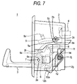
- FIG. 7 is a side view of the retractable hook apparatus in the first embodiment
- FIG. 8 is a side view showing a mounting state of the decorative plate in the first embodiment
- FIG. 9A is a side view of a rotor and FIG. 9B is a front view of the rotor and FIG. 9C is a sectional view taken on line C—C of FIG. 9A in the first embodiment;
- FIG. 10 is a sectional view of a rotation body in the first embodiment
- FIGS. 11A and 11B show a second embodiment
- FIG. 11A is a sectional view corresponding to FIG. 10
- FIG. 11B is a main exploded perspective view of a portion for applying opening and closing damping
- FIG. 12 is a main exploded perspective view showing a third embodiment
- FIGS. 13A to 13C show the third embodiment
- FIG. 13A is a sectional view seen from the end side of a rotation body
- FIG. 13B is a sectional view taken on line I—I of FIG. 13A
- FIG. 13C is a sectional view taken on line II—II of FIG. 13A ;
- FIG. 14 is an exploded perspective view of a vessel holder according to a fourth embodiment
- FIG. 15 is a main exploded perspective view of the vessel holder in the fourth embodiment.
- FIG. 16 is an exploded perspective view corresponding to FIG. 14 according to a fifth embodiment
- FIG. 17 is an exploded perspective view of a glove box according to a sixth embodiment.
- FIG. 18 is an exploded perspective view of a retractable assist grip apparatus according to a seventh embodiment.
- FIGS. 1 to 10 A first embodiment of the invention is shown in FIGS. 1 to 10 .
- An exploded perspective view of a retractable hook apparatus is shown in FIG. 1 .
- FIG. 1 Numeral 1 of FIG. 1 is a retractable hook apparatus to which the invention is applied, and is provided in the vehicle interior.
- a retractable hook apparatus 1 comprises a retracting case 2 acting as a support body mounted in the side of a vehicle body and a hook 3 rotatably supported in the retracting case 2 , and the hook 3 is opened and closed with respect to the retracting case 2 through a well-known push and push mechanism.
- the hook 3 is used in the case of hooking a shopping bag etc. and when the hook is not used, the hook 3 is retracted in the retracting case 2 .
- the retracting case 2 is attached to a recess (not shown) formed in the vehicle body and is positioned and also is fixed in the vehicle body side by a screw 4 inserted into a screw insertion hole 2 a bored in the upper side of a depth surface.
- the front of the screw insertion hole 2 a is hidden by a decorative plate 5 .
- bosses 5 a are formed in both sides of a lower portion of the decorative plate 5 , and a notch 5 b for opened position holding and a notch 5 c for closed position holding are respectively formed in an outer circumference of the boss 5 a .
- a support hole part 2 b for rotatably supporting the boss 5 a is bored in the side of the retracting case 2 , and a pawl part 2 c integrally formed in the retracting case 2 faces this support hole part 2 b .
- hook parts 5 d are integrally formed in both sides of an upper portion of the decorative plate 5 .
- hole parts 2 d for engaging and stopping the hook parts 5 d are bored in the bottom of the retracting case 2 .
- the notches 5 b for opened position holding formed in the bosses 5 a are engaged and stopped in the pawl parts 2 c to maintain an opened state. Therefore, even when the decorative plate 5 is influenced by vibration etc. at the time of transfer, the decorative plate 5 does not rattle and can hold the opened state. Also, by rotating the decorative plate 5 after the retracting case 2 is fixedly provided in the vehicle body through the screw 4 , as shown by a solid line in FIG.
- a rotation body 6 is integrally formed in a base of the hook 3 rotatably held in the retracting case 2 .
- a shaft hole 6 a is bored in the center of rotation of the rotation body 6 .
- another shaft hole 2 e is bored in a position corresponding to the shaft hole 6 a of the side of the retracting case 2 .
- a support shaft 7 acting as a shaft body is inserted into both the shaft holes 6 a , 2 e and the rotation body 6 is rotatably supported in the retracting case 2 through the support shaft 7 .
- an annular groove part 6 b with a predetermined depth is formed on the same axis as that of the shaft hole 6 a and one end of the rotation body 6 , and a spring receiving recess 6 f (see FIG. 10 ) is formed in the other end.
- a bracket 8 is radially protruded from the side of the rotation body 6 and a lock pin 11 forming a push and push mechanism 10 is protrusively provided in one end of the top of the bracket 8 .
- the push and push mechanism 10 is a mechanism for opening and closing the hook 3 using a heart cam mechanism.
- a relief hole 2 f for backward protruding the bracket 8 is bored in the retracting case 2 and a support bracket 2 g is protrusively provided in one side of the relief hole 2 f .
- a support pin 2 j is protrusively provided in one side of the support bracket 2 g .
- One end of a swing cam 12 is swingably supported in this support pin 2 j through a damping washer 13 formed of non-woven fabric etc. in a state in which movement in an axial direction is allowed.
- the swing cam 12 is always energized to the front of the retracting case 2 by energization force of a spring 14 for cam and also is energized to the side of the support bracket 2 g by weak force.
- a well-known heart cam groove 12 a is formed in the swing cam 12 and the lock pin 11 is engaged into this heart cam groove 12 a .
- an engagement stop groove part 12 b for engaging and stopping the lock pin 11 and holding the hook 3 in a closed position is formed in the heart cam groove 12 a.
- the hook 3 is always energized in an opened direction by energization force of a spring 15 for hook.
- a wall part 6 c (see FIG. 1 ) overhanging in a tangent direction from a circumferential wall of the bracket 8 of the rotation body 6 abuts on a receiving part 2 h formed in the bottom of the retracting case 2 and the opened state is maintained.
- the hook 3 rotates about the support shaft 7 in a closed direction against the energization force of the spring 15 for hook.
- a damper mechanism 16 f or slowly opening the hook 3 is provided together.
- a rotor 17 is attached to the annular groove part 6 b formed in the rotation body 6 as shown in FIGS. 1 and 10 .
- the rotor 17 is formed of an elastic body such as rubber in substantially cylindrical shape, and the outer circumference is somewhat smaller than a diameter of a large diameter side wall surface 6 c of the annular groove part 6 b and also, the inner circumference is formed somewhat larger than a diameter of a small diameter side wall surface 6 d.
- a pair of opposed engagement stop parts 17 a are formed in one end of the rotor 17 .
- protrusion elongated parts 2 i for engaging with inner surfaces of the engagement stop parts 17 a are mutually parallel provided in a surface of the retracting case 2 opposed to the engagement stop parts 17 a in a state of sandwiching the shaft hole 2 e in a depth direction from an opening plane of the retracting case 2 (see FIG. 3A ).
- the protrusion elongated part 2 i is formed in a length capable of being received in an inner circumference of the annular groove part 6 b , and a relief groove part 6 e for avoiding interference with the protrusion elongated parts 2 i at the time of assembly is formed in the end of the rotation body 6 . Further, the end of the shaft hole 6 a of the rotation body 6 is retracted somewhat inwardly in order to avoid interference with the protrusion elongated parts 2 i.
- a first elastic annulus 17 b is formed in the middle of an outer circumference of the rotor 17 .
- a first protrusion elongated annular part 17 c of the top of the first elastic annulus 17 b is formed in a diameter somewhat larger than that of the large diameter side wall surface 6 c of the annular groove part 6 b formed in the rotation body 6 and also is formed in relatively thin-walled cup shape inclined in a direction of the engagement stop parts 17 a.
- air relief grooves 17 d are formed in the outer circumference of the rotor 17 .
- the air relief grooves 17 d are formed from the other end (the end opposite to the end in which the engagement stop parts 17 a are protrusively provided) of the rotor 17 to a position of a predetermined height.
- the air relief grooves 17 d are formed in two places in an evenly spaced position, but may be formed in three or more places or one place. Further, the air relief grooves 17 d may be formed in an inner circumference of the rotor 17 .
- a second elastic annulus 17 e with a relatively thin wall is formed along an axial direction to the side of the engagement stop parts 17 a of the inner circumference of the rotor 17 .
- the second elastic annulus 17 e is formed by forming an annular groove in the outer circumference from the axial middle of the rotor 17 toward the engagement stop parts 17 a.
- a second protrusion elongated annular part 17 f with a diameter somewhat smaller than that of the small diameter side wall surface 6 d of the annular groove part 6 b of the rotation body 6 is formed in an inner circumference of the top end of the second elastic annulus 17 e.
- the second elastic annulus 17 e and the first protrusion elongated annular part 17 c of the first elastic annulus 17 b formed in the rotor 17 are provided in a position offset in an axial direction.
- the first protrusion elongated annular part 17 c of the first elastic annulus 17 b is formed in the other end side (the end side opposite to the end in which the engagement stop parts 17 a are protrusively provided) from the second elastic annulus 17 e , but the first protrusion elongated annular part 17 c of the first elastic annulus 17 b may be formed in the side of the engagement stop parts 17 a from the second elastic annulus 17 e.
- a relatively large amount of deformation in the case of elastically deforming the first elastic annulus 17 b and the second elastic annulus 17 e in a radial direction can be secured by offsetting the second elastic annulus 17 e and the first protrusion elongated annular part 17 c of the first elastic annulus 17 b in the axial direction.
- grease 18 acting as a viscous member having a predetermined viscosity is charged between the annular groove part 6 b formed in the rotation body 6 and the rotor 17 inserted into this annular groove part 6 b.
- a proper amount of grease 18 having a predetermined viscosity is first charged into the annular groove part 6 b of the rotation body 6 integrally formed in a base of the hook 3 .
- the rotor 17 having elasticity is attached to this annular groove part 6 b .
- the outer circumference of the rotor 17 is formed somewhat smaller than a diameter of the large diameter side wall surface 6 c of the annular groove part 6 b and the inner circumference is formed somewhat larger than a diameter of the small diameter side wall surface 6 d of the annular groove part 6 b , so that the grease 18 penetrates into a gap between them.
- both the wall surfaces 6 c , 6 d of the annular groove part 6 b are sealed with each of the elastic annuli 17 b , 17 e formed in the rotor 17 and the grease 18 is sealed in the inside and air is also sealed at the same time.
- the air sealed in the inside is released to the air relief grooves 17 d formed along an axial direction in the outer circumference of the rotor 17 , so that the air is not compressed more than necessary and a burst of the rotor 17 and leakage of the grease 18 are prevented.
- the rotation body 6 formed in the base of the hook 3 is assembled in the retracting case 2 .
- the swing cam 12 constructing the push and push mechanism 10 is assembled in the support pin 2 j protrusively provided in the support bracket 2 g formed in a depth surface of the retracting case 2 in a predetermined manner.
- a range between opposed surfaces of a pair of the engagement stop parts 17 a protrusively provided in the top side of the rotor 17 is aligned with the relief groove part 6 e formed in the end of the rotation body 6 .
- a coil part of the spring 15 for hook is received in the spring receiving recess 6 f formed in the other end of the rotation body 6 .
- the relief groove part 6 e of the rotation body 6 is inserted so as to straddle a pair of the protrusion elongated parts 2 i protrusively provided in the side of the retracting case 2 and opposed surfaces of a pair of the engagement stop parts 17 a formed in the rotor 17 are engaged in the outsides of the protrusion elongated parts 2 i and also the shaft hole 6 a of the rotation body 6 is guided to the shaft hole 2 e bored in the side of the retracting case 2 . Also, one end of the spring 15 for hook is engaged and stopped in the retracting case 2 .
- the support shaft 7 is inserted into the mutually guided shaft holes 2 e , 6 a from the outside and the rotation body 6 is rotatably supported in the retracting case 2 through the support shaft 7 .
- the engagement stop parts 17 a of the rotor 17 are engaged in the protrusion elongated parts 2 i formed in the retracting case 2 , so that rotation of the rotor 17 is regulated.
- the bracket 8 protrusively provided in a radial direction from an outer circumference of the rotation body 6 is protruded from the relief hole 2 f bored in a depth surface of the retracting case 2 to the depth surface.
- the lock pin 11 protruded from the bracket 8 to the side can be engaged in the heart cam groove 12 a formed in the swing cam 12 .
- the hook 3 is always energized in an opened direction by energization force of the spring 15 for hook.
- the decorative plate 5 for hiding the screw 4 after assembly is mounted in an upper portion inside the retracting case 2 . That is, the bosses 5 a protrusively provided in both sides of a lower portion of the decorative plate 5 are supported in the support hole parts 2 b bored in both sides of the retracting case 2 . Further, the pawl parts 2 c facing the support hole parts 2 b are engaged in the notches 5 b for opened position holding formed in the bosses 5 a and an opened state of the decorative plate 5 is maintained as shown by a wavy line in FIG. 7 .
- the notches 5 b for opened position holding formed in the bosses 5 a are engaged and stopped by the pawl parts 2 c , so that the decorative plate 5 does not rattle even in the case of being influenced by vibration etc. at the time of transfer.
- the retractable hook apparatus 1 assembled in this manner is mounted in the vehicle interior.
- the retracting case 2 is attached to a recess (not shown) previously formed in the vehicle interior and the screw 4 is inserted into the screw insertion hole 2 a bored in a depth surface of the retracting case 2 and this screw 4 is screwed into a vehicle body and the retracting case 2 is fixed in the vehicle body.
- the decorative plate 5 is rotated about the bosses 5 a and the notches 5 c for closed position holding formed in the bosses 5 a are engaged in the pawl parts 2 c as shown in FIG. 8 . Further, the hook parts 5 d formed in both sides of an upper portion of the decorative plate 5 are engaged in the hole parts 2 d bored in a depth surface of the retracting case 2 to maintain a closed state and the screw 4 is hidden and assembly is completed.
- the hook 3 receives energization force of the spring 15 for hook and is in an opened state as shown in FIGS. 2B and 7 .
- the hook 3 maintains the opened state by abutting the wall part 6 c of the rotation body 6 on the receiving part 2 h formed in the bottom of the retracting case 2 .
- the lock pin 11 protruded from the side of the bracket 8 disengages from the heart cam groove 12 a formed in the swing cam 12 .
- the hook 3 When the hook 3 is pressed from such a state in a retracting direction against the energization force of the spring 15 for hook, the hook 3 rotates with the hook 3 supported in the support shaft 7 inserted into the shaft hole 6 a of the rotation body 6 . At that time, the lock pin 11 engages into the heart cam groove 12 a formed in the swing cam 12 .
- the swing cam 12 receives energization force of the spring 14 for cam and swings along movement of the lock pin 11 .
- the lock pin 11 disengages from the heart cam groove 12 a formed in the swing cam 12 .
- the swing cam 12 is pressed by the lock pin 11 and somewhat swings in an axial direction and when the lock pin 11 disengages from the swing cam 12 , the swing cam 12 is returned by the energization force of the spring 14 for cam. At that time, small impact sound is emitted, but the impact sound is deadened by the damping washer 13 interposed between the swing cam 12 and the support bracket 2 g.
- the grease 18 has a predetermined viscosity and is sealed by the first elastic annulus 17 b and the second elastic annulus 17 e formed in the rotor 17 , so that the grease 18 does not leak to the outside and high reliability can be ensured. Also, since it is constructed so that the grease 18 is sealed by shape of the rotor 17 without providing a seal member separately, simplification of structure can be achieved.
- the present embodiment it is constructed so as to seal the grease 18 by the elastic annuli 17 b , 17 e formed in the rotor 17 , so that even when oil is used instead of the grease 18 , the oil does not leak to the outside. Therefore, damping with respect to the hook 3 can be adjusted by properly selecting viscosity of the grease 18 or the oil, so that high versatility can be obtained. Also, a plurality of the air relief grooves 17 d may be formed in a recessed state in a position between the first elastic annulus 17 b and the second elastic annulus 17 e.
- FIGS. 11A and 11B A second embodiment of the invention is shown in FIGS. 11A and 11B .
- the case of attaching a rotation body 6 from a perpendicular direction with respect to a mounting surface of a retracting case 2 etc. will be illustrated.
- description is omitted by attaching the same numerals to the same configuration portions as those of the first embodiment.
- a first elastic annulus 17 b and a second elastic annulus 17 e are formed in the substantially same position of the top side of a rotor 17
- a first protrusion elongated annular part 17 c and a second protrusion elongated annular part 17 f are respectively formed in the top outer circumference and the top inner circumference of each of the elastic annuli 17 b, 17 e
- a groove part 17 g with circular arc shape into which a pair of opposed protrusion parts 2 k protrusively provided from the side of a retracting case 2 in circular arc shape about a shaft hole 2 e are fitted is formed in the bottom of a groove part of cylindrical shape with the bottom surrounded by the first elastic annulus 17 b and the second elastic annulus 17 e.
- a slidingly abutting region between the rotor 17 and grease 18 can be provided in the substantially whole of an axial direction, so that higher damping effect can be obtained.
- air relief grooves similar to those of the first embodiment may be formed along an axial direction in an outer circumference of the rotor 17 .
- the air relief grooves may be formed continuously in the range from the end of the bottom side of the annular groove part 6 b to at least one of the first elastic annulus 17 b and the second elastic annulus 17 e of the rotor 17 .
- FIGS. 12 and 13A to 13 C A third embodiment of the invention is shown in FIGS. 12 and 13A to 13 C.
- the case of parallel attaching a rotation body 6 with respect to a mounting surface of a retracting case 2 etc. in a manner similar to the case of the first embodiment will be illustrated.
- description is omitted by attaching the same numerals to the same configuration portions as those of the first embodiment.
- a first elastic annulus 17 b and a second elastic annulus 17 e formed in a rotor 17 are formed in a position similar to that of the second embodiment.
- the protrusion elongated parts 2 i protrusively provided in the side of a mounting surface are engaged in a pair of the opposed engagement stop parts 17 a formed in the rotor 17
- it is constructed so that rotation of the rotor 17 is regulated by attaching the ends of a pair of opposed engagement stop parts 17 h which have circular arc shape about a shaft hole 6 a and are protrusively provided from the bottom of a groove part of cylindrical shape with the bottom surrounded by the first elastic annulus 17 b and the second elastic annulus 17 e so as to pinch and support the ends of the engagement stop parts 17 h between protrusion elongated parts 2 i.
- FIGS. 14 and 15 A fourth embodiment of the invention is shown in FIGS. 14 and 15 .
- the case of applying the invention to a vessel holder 21 will be described.
- the vessel holder 21 is provided in a center console (not shown) etc. of the vehicle interior, and has a holder body 22 and a lid 23 for opening and closing an upper surface of the holder body 22 .
- the lid 23 is opened and closed by the substantially same configuration as that of the push and push mechanism 10 shown in the first embodiment. Therefore, description is omitted by attaching the same numeral to a configuration of a push and push mechanism 10 .
- a damper mechanism 16 basically has a configuration similar to that of the first embodiment. That is, an annular groove part 6 b with a predetermined depth in one side of the back of the holder body 22 is formed in a manner similar to the rotation body 6 of the first embodiment. A rotor 17 is attached to this annular groove part 6 b.
- a top surface of the rotor 17 is blocked, and one elongated engagement stop part 17 j passing through a center line is protrusively provided in the top surface.
- a pair of hinge brackets 23 a are oppositely provided at a predetermined spacing in the inside of the base side of the lid 23 , and a groove part 23 c for engaging in the engagement stop part 17 j protrusively provided in the rotor 17 is formed in an opposed surface of one hinge bracket 23 a.
- the other hinge bracket 23 a is rotatably supported in the other side of the back of the holder body 22 through a support shaft 24 and also is always energized in an opened direction by a spring 25 for lid. Further, disengagement stop in an axial direction is made by a screw 26 .
- the engagement stop part 17 j of the rotor 17 is engaged in the groove part 23 c formed in one hinge bracket 23 a , so that the rotor 17 rotates integrally with the lid 23 .
- the rotor 17 is inserted into the annular groove part 6 b formed in the side of the holder body 22 and grease 18 (see FIG. 10 ) is charged between the annular groove part 6 b and the rotor 17 , so that with rotation of the lid 23 in an opened direction, the rotor 17 is damped by fluid resistance of the grease 18 and the lid 23 is slowly opened.
- FIG. 16 a fifth embodiment of the invention is shown in FIG. 16 .
- the present embodiment is a modified example of the fourth embodiment described above.
- the engagement stop part 17 j formed in the top surface of the rotor 17 is engaged in the groove part 23 c of the hinge bracket 23 a , but in the present embodiment, a square engagement stop part 17 k is protrusively provided in the center of a rotor 17 and a square hole 23 d for engaging in the engagement stop part 17 k is bored in a hinge bracket 23 a.
- the fourth embodiment can be applied to the case of engaging the engagement stop part 17 j of the rotor 17 from a parallel direction with respect to the hinge bracket 23 a , but the present embodiment can be applied to the case of engaging the engagement stop part 17 k protrusively provided in the rotor 17 from a perpendicular direction with respect to the square hole 23 d of the hinge bracket 23 a.
- FIG. 17 A sixth embodiment of the invention is shown in FIG. 17 .
- the case of applying the invention to a glove box 31 will be described.
- a lid 33 for opening and closing a box body 32 of the glove box 31 the surface area is relatively wide and the weight is large by the wide surface area as compared with the hook 3 of the retractable hook apparatus 1 or the lid 23 of the vessel holder 21 , so that the lid 33 can be opened by the own weight.
- a spring for energizing the lid 33 in an opened direction is unnecessary. Also, since it is constructed so that the lid 33 is closed by engaging a latch 35 provided in the lid 33 into a striker 36 provided in the box body 32 and is opened by releasing engagement of the latch 35 with the striker 36 , a push and push mechanism 10 is also unnecessary.
- a rotation body 6 having a configuration similar to that of the first embodiment is fixedly provided in a base of the lid 33 , and a rotor 17 is attached to an annular groove part 6 b with a predetermined depth formed in this rotation body 6 .
- the rotor 17 has a configuration similar to that of the fourth embodiment and an engagement stop part 17 j formed in the top is engaged in a groove part 23 c formed in the side of the box body 32 and the rotor 17 is rotatably supported by a support shaft 7 .
- the rotor 17 is engaged in the groove part 23 c formed in the box body 32 and rotation is regulated, so that the lid 33 is damped by fluid resistance of grease 18 charged between the annular groove part 6 b and the rotor 17 and is slowly opened.
- FIG. 18 A seventh embodiment of the invention is shown in FIG. 18 .
- the case of applying the invention to a retractable assist grip apparatus 41 will be described.
- elastic legs 42 c , 42 d are pushed and engaged in mounting holes formed in an upper portion of a side wall of the vehicle interior and thereby a pair of support bodies 42 a , 42 b are fixedly provided at a predetermined spacing in the upper portion of the side wall and both ends of a grip 43 are rotatably supported in each of the support bodies 42 a , 42 b through a support shaft 7 , respectively.
- a rotation body 6 is formed integrally with one support body 42 a .
- This rotation body 6 has a configuration similar to that of the first embodiment and a rotor 17 is attached to an annular groove part 6 b (see FIG. 10 ) with a predetermined depth formed in the inside. Also, the rotor 17 has a configuration similar to that of the fourth embodiment.
- An engagement stop part 17 j formed in a top surface of the rotor 17 is engaged in a groove part 23 c formed in the grip 43 to rotate integrally with the grip 43 . Also, both ends of a spring 45 for grip are engaged and stopped in a groove 42 e formed in the other support body 42 b and a groove 43 a formed in the grip 43 and the grip 43 is energized in a direction abutting on the side wall.
- the grip 43 is normally retracted into the side wall of the vehicle interior in a folded state by energization force of the spring 45 for grip.
- An opening and closing damping apparatus of the invention can be applied to not only structure bodies having various opening and closing mechanisms provided in the vehicle interior of a vehicle such as an automobile, for example, a retractable hook apparatus, a retractable assist grip apparatus, a retractable storage box, a cup holder, a glove box, a console box for storing a small article, eyeglasses, an ashtray having a push and push mechanism but also structure bodies other than the vehicle.
Landscapes
- Engineering & Computer Science (AREA)
- Mechanical Engineering (AREA)
- General Engineering & Computer Science (AREA)
- Fluid-Damping Devices (AREA)
- Braking Arrangements (AREA)
- Vehicle Step Arrangements And Article Storage (AREA)
Applications Claiming Priority (2)
| Application Number | Priority Date | Filing Date | Title |
|---|---|---|---|
| JP2003300110A JP3966842B2 (ja) | 2003-08-25 | 2003-08-25 | 開閉制動装置 |
| JPP.2003-300110 | 2003-08-25 |
Publications (2)
| Publication Number | Publication Date |
|---|---|
| US20050076471A1 US20050076471A1 (en) | 2005-04-14 |
| US7240398B2 true US7240398B2 (en) | 2007-07-10 |
Family
ID=34405147
Family Applications (1)
| Application Number | Title | Priority Date | Filing Date |
|---|---|---|---|
| US10/924,259 Expired - Lifetime US7240398B2 (en) | 2003-08-25 | 2004-08-24 | Opening and closing damping apparatus |
Country Status (3)
| Country | Link |
|---|---|
| US (1) | US7240398B2 (ko) |
| JP (1) | JP3966842B2 (ko) |
| KR (1) | KR101068562B1 (ko) |
Cited By (7)
| Publication number | Priority date | Publication date | Assignee | Title |
|---|---|---|---|---|
| US20090250579A1 (en) * | 2008-04-08 | 2009-10-08 | Nifco Inc. | Apparatus with a rotating body |
| US20100077571A1 (en) * | 2008-09-30 | 2010-04-01 | Nifco, Inc. | Operational mechanism for movable body |
| US20110215606A1 (en) * | 2010-03-08 | 2011-09-08 | Nissan Technical Center North America, Inc. | Console lid friction hinge |
| US20120073919A1 (en) * | 2009-06-03 | 2012-03-29 | Illinois Tool Works Inc. | Hinge damper assembly |
| US20130126570A1 (en) * | 2011-11-21 | 2013-05-23 | Ford Global Technologies, Llc | Retracting storage tray system with locking trunnion |
| US20170057418A1 (en) * | 2015-08-28 | 2017-03-02 | Newfrey Llc | Hook device for use in a vehicle |
| US10080454B2 (en) * | 2014-12-05 | 2018-09-25 | Piolax, Inc. | Retaining device |
Families Citing this family (12)
| Publication number | Priority date | Publication date | Assignee | Title |
|---|---|---|---|---|
| KR100778898B1 (ko) * | 2006-05-09 | 2007-11-27 | 주식회사 우성엔터프라이즈 | 안전 로터리 힌지장치 |
| JP2008213716A (ja) * | 2007-03-06 | 2008-09-18 | Nifco Inc | 回動開閉部材の取付構造 |
| EP2025557A1 (de) * | 2007-08-07 | 2009-02-18 | Delphi Technologies, Inc. | Verbindungsmodulbaugruppe |
| JP5038195B2 (ja) | 2008-03-10 | 2012-10-03 | 株式会社ニフコ | 格納式フック装置 |
| WO2010117531A1 (en) * | 2009-04-08 | 2010-10-14 | Illinois Tool Works Inc. | Pivoting hook retention system |
| JP5134590B2 (ja) * | 2009-06-19 | 2013-01-30 | 株式会社パイオラックス | 機能部品の取付構造 |
| US8490935B2 (en) * | 2009-10-28 | 2013-07-23 | Honda Motor Co., Ltd. | Multipurpose hook |
| US9371674B2 (en) | 2012-03-26 | 2016-06-21 | Itt Manufacturing Enterprises Llc | Rotary hydraulic damper for pivoting stowage bin |
| US8820597B2 (en) * | 2012-08-01 | 2014-09-02 | Ford Global Technologies, Llc | Vehicle garment hook and guard mounting assembly |
| US9561755B2 (en) | 2012-08-01 | 2017-02-07 | Ford Global Technologies, Llc | Vehicle garment hook assembly |
| CN106585505A (zh) * | 2015-10-20 | 2017-04-26 | 福特环球技术公司 | 可用于车辆上的物体接插总成 |
| US10220790B2 (en) * | 2017-01-26 | 2019-03-05 | Ford Global Technologies, Llc | Pivoting hanger with positive retention |
Citations (21)
| Publication number | Priority date | Publication date | Assignee | Title |
|---|---|---|---|---|
| US5276945A (en) * | 1991-11-05 | 1994-01-11 | Shuji Matsumura | Hinge device having directional damping |
| US5366127A (en) * | 1993-05-18 | 1994-11-22 | United Technologies Automotive, Inc. | Device for supporting garment hangers within an automotive vehicle |
| US5582276A (en) * | 1994-07-08 | 1996-12-10 | Itw De France | Rotation moderator |
| JPH1054171A (ja) | 1996-08-12 | 1998-02-24 | Nifco Inc | グリスダンパー |
| EP0830986A2 (de) * | 1996-08-21 | 1998-03-25 | Utescheny - Endos GmbH | Kleiderhakeneinrichtung, insbesondere für den Innenraum von Fahrzeugen |
| US5820205A (en) * | 1996-12-30 | 1998-10-13 | Ammons; Thomas C. | Retractable automotive hanger |
| US6076233A (en) * | 1998-05-27 | 2000-06-20 | Honda Giken Kogyo Kabushiki Kaisha | Grab rail and hook assembly for a vehicle |
| US6095469A (en) * | 1998-09-11 | 2000-08-01 | Prince Corporation | Coat hook assembly with closeout panel |
| US6397435B1 (en) * | 1999-04-22 | 2002-06-04 | Lear Corporation | Handle assembly with integrated hook |
| JP2002193012A (ja) | 2000-12-27 | 2002-07-10 | Fuji Seiki Co Ltd | アシストグリップ用ロータリーダンパ及びアシストグリップ |
| US6457690B1 (en) * | 2001-11-26 | 2002-10-01 | Johnson Controls Technology Company | Vehicle accessory combined hook and clip |
| US6467130B2 (en) * | 2000-08-10 | 2002-10-22 | Nifco Inc. | Damping structure for rotating member and assist grip including the damping structure |
| US6511036B1 (en) * | 1999-10-08 | 2003-01-28 | Johnson Controls Technology Company | Friction damper for vehicle accessories |
| US6643897B2 (en) * | 2001-10-23 | 2003-11-11 | Trw Inc. | Retractable grab handle and coat hook |
| US6662683B1 (en) * | 1999-08-05 | 2003-12-16 | Nifco Inc. | Oil cylindrical rotational damper |
| US6715813B2 (en) * | 2002-08-20 | 2004-04-06 | Johnson Controls Technology | Over-center spring control |
| US6729447B2 (en) * | 2001-10-23 | 2004-05-04 | Tok Bearing Co., Ltd. | Rotational speed controller |
| US20040163223A1 (en) * | 2003-02-07 | 2004-08-26 | Bivens Steven L. | Coat hook system with integral damper and latch |
| US6817061B2 (en) * | 2002-07-31 | 2004-11-16 | Jiin-Chang Wu | Hinge for foldable cellular phones |
| US6836932B2 (en) * | 2002-01-09 | 2005-01-04 | Nifco Inc. | Assist grip |
| US6840355B2 (en) * | 2001-12-12 | 2005-01-11 | Sankyo Seiki Mfg. Co., Ltd. | Rotary damper device |
Family Cites Families (4)
| Publication number | Priority date | Publication date | Assignee | Title |
|---|---|---|---|---|
| JPH08200407A (ja) * | 1995-01-20 | 1996-08-06 | Tateyama Alum Gaisou Kk | 流体式制動装置および該装置を使用した門扉 |
| JPH10311359A (ja) | 1997-05-07 | 1998-11-24 | Nifco Inc | 回転ダンパ |
| JP3781624B2 (ja) * | 2000-02-18 | 2006-05-31 | 株式会社パイオラックス | 回転ダンパ |
| JP2003019847A (ja) | 2001-07-09 | 2003-01-21 | Nifco Inc | 扉の制動構造 |
-
2003
- 2003-08-25 JP JP2003300110A patent/JP3966842B2/ja not_active Expired - Fee Related
-
2004
- 2004-08-24 US US10/924,259 patent/US7240398B2/en not_active Expired - Lifetime
- 2004-08-25 KR KR1020040067253A patent/KR101068562B1/ko active IP Right Grant
Patent Citations (21)
| Publication number | Priority date | Publication date | Assignee | Title |
|---|---|---|---|---|
| US5276945A (en) * | 1991-11-05 | 1994-01-11 | Shuji Matsumura | Hinge device having directional damping |
| US5366127A (en) * | 1993-05-18 | 1994-11-22 | United Technologies Automotive, Inc. | Device for supporting garment hangers within an automotive vehicle |
| US5582276A (en) * | 1994-07-08 | 1996-12-10 | Itw De France | Rotation moderator |
| JPH1054171A (ja) | 1996-08-12 | 1998-02-24 | Nifco Inc | グリスダンパー |
| EP0830986A2 (de) * | 1996-08-21 | 1998-03-25 | Utescheny - Endos GmbH | Kleiderhakeneinrichtung, insbesondere für den Innenraum von Fahrzeugen |
| US5820205A (en) * | 1996-12-30 | 1998-10-13 | Ammons; Thomas C. | Retractable automotive hanger |
| US6076233A (en) * | 1998-05-27 | 2000-06-20 | Honda Giken Kogyo Kabushiki Kaisha | Grab rail and hook assembly for a vehicle |
| US6095469A (en) * | 1998-09-11 | 2000-08-01 | Prince Corporation | Coat hook assembly with closeout panel |
| US6397435B1 (en) * | 1999-04-22 | 2002-06-04 | Lear Corporation | Handle assembly with integrated hook |
| US6662683B1 (en) * | 1999-08-05 | 2003-12-16 | Nifco Inc. | Oil cylindrical rotational damper |
| US6511036B1 (en) * | 1999-10-08 | 2003-01-28 | Johnson Controls Technology Company | Friction damper for vehicle accessories |
| US6467130B2 (en) * | 2000-08-10 | 2002-10-22 | Nifco Inc. | Damping structure for rotating member and assist grip including the damping structure |
| JP2002193012A (ja) | 2000-12-27 | 2002-07-10 | Fuji Seiki Co Ltd | アシストグリップ用ロータリーダンパ及びアシストグリップ |
| US6729447B2 (en) * | 2001-10-23 | 2004-05-04 | Tok Bearing Co., Ltd. | Rotational speed controller |
| US6643897B2 (en) * | 2001-10-23 | 2003-11-11 | Trw Inc. | Retractable grab handle and coat hook |
| US6457690B1 (en) * | 2001-11-26 | 2002-10-01 | Johnson Controls Technology Company | Vehicle accessory combined hook and clip |
| US6840355B2 (en) * | 2001-12-12 | 2005-01-11 | Sankyo Seiki Mfg. Co., Ltd. | Rotary damper device |
| US6836932B2 (en) * | 2002-01-09 | 2005-01-04 | Nifco Inc. | Assist grip |
| US6817061B2 (en) * | 2002-07-31 | 2004-11-16 | Jiin-Chang Wu | Hinge for foldable cellular phones |
| US6715813B2 (en) * | 2002-08-20 | 2004-04-06 | Johnson Controls Technology | Over-center spring control |
| US20040163223A1 (en) * | 2003-02-07 | 2004-08-26 | Bivens Steven L. | Coat hook system with integral damper and latch |
Cited By (11)
| Publication number | Priority date | Publication date | Assignee | Title |
|---|---|---|---|---|
| US20090250579A1 (en) * | 2008-04-08 | 2009-10-08 | Nifco Inc. | Apparatus with a rotating body |
| US8186638B2 (en) * | 2008-04-08 | 2012-05-29 | Nifco Inc. | Apparatus with a rotating body |
| US20100077571A1 (en) * | 2008-09-30 | 2010-04-01 | Nifco, Inc. | Operational mechanism for movable body |
| US8079446B2 (en) * | 2008-09-30 | 2011-12-20 | Nifco Inc. | Operational mechanism for movable body |
| US20120073919A1 (en) * | 2009-06-03 | 2012-03-29 | Illinois Tool Works Inc. | Hinge damper assembly |
| US9297195B2 (en) * | 2009-06-03 | 2016-03-29 | Illinois Tool Works Inc. | Hinge damper assembly |
| US20110215606A1 (en) * | 2010-03-08 | 2011-09-08 | Nissan Technical Center North America, Inc. | Console lid friction hinge |
| US20130126570A1 (en) * | 2011-11-21 | 2013-05-23 | Ford Global Technologies, Llc | Retracting storage tray system with locking trunnion |
| US8573668B2 (en) * | 2011-11-21 | 2013-11-05 | Ford Global Technologies, Llc | Retracting storage tray system with locking trunnion |
| US10080454B2 (en) * | 2014-12-05 | 2018-09-25 | Piolax, Inc. | Retaining device |
| US20170057418A1 (en) * | 2015-08-28 | 2017-03-02 | Newfrey Llc | Hook device for use in a vehicle |
Also Published As
| Publication number | Publication date |
|---|---|
| JP2005068812A (ja) | 2005-03-17 |
| KR20050021286A (ko) | 2005-03-07 |
| KR101068562B1 (ko) | 2011-09-28 |
| US20050076471A1 (en) | 2005-04-14 |
| JP3966842B2 (ja) | 2007-08-29 |
Similar Documents
| Publication | Publication Date | Title |
|---|---|---|
| US7240398B2 (en) | Opening and closing damping apparatus | |
| US5605208A (en) | Rotary damper | |
| US6019334A (en) | Cup holder with divided lid portions | |
| EP1503111B1 (en) | Damper device | |
| US20060032021A1 (en) | Hinge structure, hinge unit having the hinge structure, and container having cover attached thereto with the hinge structure | |
| US6968601B2 (en) | Coat hook system with integral damper and latch | |
| CA2431613C (en) | One-way damper | |
| US7510062B2 (en) | Rotary damper | |
| US8079450B2 (en) | Viscous strand damper assembly | |
| US9382965B2 (en) | Self-aligning rotary damper assembly | |
| JPWO2005095742A1 (ja) | ダンパー付きヒンジ | |
| US20050034269A1 (en) | Damper | |
| CN101660380B (zh) | 阻尼器 | |
| US20150020349A1 (en) | Door hinge of vehicle | |
| US9834123B2 (en) | Retaining clip for a door assembly | |
| MX2012005741A (es) | Estructura de ruptura para cuerpo giratorio. | |
| US20140130299A1 (en) | Soft close mechanism for a closure | |
| US20150275997A1 (en) | Variable rate friction damper | |
| US6526644B2 (en) | Retractable assist grip and mounting method thereof | |
| US9493968B2 (en) | Striker with expandable sleeve | |
| KR100407566B1 (ko) | 회전체의 제동구조 | |
| JP3689874B2 (ja) | ロータリーダンパー | |
| JP4200166B2 (ja) | 車両用収納装置 | |
| JPH0681876A (ja) | 回転ダンパ | |
| JP2007247882A (ja) | ダンパー |
Legal Events
| Date | Code | Title | Description |
|---|---|---|---|
| AS | Assignment |
Owner name: PIOLAX, INC., JAPAN Free format text: ASSIGNMENT OF ASSIGNORS INTEREST;ASSIGNORS:WATANABE, TOSHIKO;HIRANO, TETSUJI;REEL/FRAME:016088/0689;SIGNING DATES FROM 20040819 TO 20040825 |
|
| STCF | Information on status: patent grant |
Free format text: PATENTED CASE |
|
| FPAY | Fee payment |
Year of fee payment: 4 |
|
| FPAY | Fee payment |
Year of fee payment: 8 |
|
| MAFP | Maintenance fee payment |
Free format text: PAYMENT OF MAINTENANCE FEE, 12TH YEAR, LARGE ENTITY (ORIGINAL EVENT CODE: M1553); ENTITY STATUS OF PATENT OWNER: LARGE ENTITY Year of fee payment: 12 |