US7119299B2 - Work inspection system - Google Patents
Work inspection system Download PDFInfo
- Publication number
- US7119299B2 US7119299B2 US10/758,202 US75820204A US7119299B2 US 7119299 B2 US7119299 B2 US 7119299B2 US 75820204 A US75820204 A US 75820204A US 7119299 B2 US7119299 B2 US 7119299B2
- Authority
- US
- United States
- Prior art keywords
- work
- works
- conveyor table
- inspection system
- storing
- Prior art date
- Legal status (The legal status is an assumption and is not a legal conclusion. Google has not performed a legal analysis and makes no representation as to the accuracy of the status listed.)
- Expired - Fee Related
Links
Images


Classifications
-
- B—PERFORMING OPERATIONS; TRANSPORTING
- B07—SEPARATING SOLIDS FROM SOLIDS; SORTING
- B07C—POSTAL SORTING; SORTING INDIVIDUAL ARTICLES, OR BULK MATERIAL FIT TO BE SORTED PIECE-MEAL, e.g. BY PICKING
- B07C5/00—Sorting according to a characteristic or feature of the articles or material being sorted, e.g. by control effected by devices which detect or measure such characteristic or feature; Sorting by manually actuated devices, e.g. switches
- B07C5/34—Sorting according to other particular properties
- B07C5/344—Sorting according to other particular properties according to electric or electromagnetic properties
Definitions
- the present invention relates to a work inspection system for inspecting (checking and measuring) such works as chip-type electronic components, while conveying the same.
- a work inspection system which includes a conveyor table with a storing groove which is outwardly opened and disposed at an outer periphery of the conveyor table, and a work inspection apparatus which inspects works stored in the storing groove of the conveyor table. (See, for example, Japanese Patent Laid-Open Publication No. 181214/1995).
- the works are supplied to the conveyor table and inserted in the storing groove. Then, with a rotation of the conveyor table, the works are conveyed to the work inspection apparatus which inspects (checks and measures) the works.
- the works supplied to the conveyor table are stored in the storing groove which is outwardly opened and disposed at the outer periphery of the conveyor table.
- the works stored in the storing groove of the conveyor table are conveyed in accordance with a rotation of the conveyor table. Since the storing groove is outwardly opened, it is difficult to convey and inspect the works while stably holding them in the storing groove.
- a work is generally of a rectangular parallelepiped shape. An inspection of such a work is carried out via electrodes disposed on ends of the longest edges of the works.
- the work in the storing groove must have electrodes in a vertical direction of the conveyor table. Therefore, a dimension of the storing groove is formed such that the work can enter the storing groove from a side of the electrodes, but that the work cannot enter the same from the longest edges.
- a storing efficiency of the works in the storing groove is degraded.
- the present invention is made in light of the above disadvantages. It is an object of the present invention to provide a work inspection system which can supply and convey the works by a conveyor table while stably holding the works.
- a work inspection system comprises: a conveyor table vertically positioned, and including a plurality of work-storing pockets for storing works, the work-storing pockets being formed inside the periphery of the conveyor table; a work supply apparatus for supplying the works to the conveyor table; a work inspection apparatus for inspecting the works stored in the work-storing pockets of the conveyor table, the work inspection apparatus being disposed near the conveyor table; and a sorting and ejecting apparatus for sorting the inspected works stored in the work-storing pockets of the conveyor table in accordance with a property of the works and ejecting the same; wherein the work-storing pockets of the conveyor table are positioned along one or more concentric circles.
- a table base may be disposed on a rear surface of the conveyor table; and circumferential vacuum sucking grooves, which are in communication with the work-storing pockets of the conveyor table and in communication with a vacuum system, may be formed in the table base.
- the work-storing pockets of the conveyor tables may be in communication with the vacuum sucking grooves of the table base through communication grooves.
- the work supply apparatus may include an inclined guide chute for supplying the works, which is downwardly inclined to the conveyor table; and a distribution chute for introducing the works from the inclined chute to the work-storing pockets.
- the work supply apparatus may include a horizontal guide chute for supplying the works, which is horizontally extended to the conveyor table; and a distribution chute for introducing the works from the horizontal guide chute to the work-storing pockets.
- a driving mechanism for driving the works in the horizontal guide chute may be disposed on the horizontal guide chute.
- the distribution chute may have V-shaped transfer grooves which are in communication with the work-storing pockets.
- the work supply apparatus may include the horizontal guide chute for supplying the works, which is horizontally extended to the conveyor table, and the horizontal guide chute may have V-shaped transfer grooves which are in communication with the work-storing pockets.
- each V-shaped groove may have a V-shaped cross-section whose opening degree is equal to or more than 90°.
- the work supply apparatus may further include means for detecting a remaining amount of the works in the distribution chute.
- the work inspection apparatus may have a pair of probes being capable of contacting the works in the work-storing pockets from the front and rear surfaces of the conveyor table, and the probe on the rear surface side of the conveyor table may be supported by a base which is disposed on the rear surface of the conveyor table through the table base.
- the probe on the rear surface side of the conveyor table may be held on the base by a clamp bar which is slid on the base by a rotation of an eccentric cam.
- the sorting and ejecting apparatus may include means for jetting air to the works in the work-storing pockets, the means being disposed on the rear surface side of the conveyor table.
- a pusher for pushing the conveyor table to disengage the same from the table base may be disposed on the rear surface side of the conveyor table.
- FIG. 1 is a view showing an automatic inspecting and sorting apparatus in which a work inspection system according to the present invention is installed;
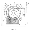
- FIG. 2 is a view showing a first embodiment of a work inspection system according to the present invention
- FIG. 3 is a cross-sectional view of the work inspection system shown in FIG. 2 ;
- FIG. 4 is a front view of the work inspection system shown in FIG. 2 ;
- FIG. 5 is a view showing the work inspection system shown in FIG. 2 , with a cover unit being detached therefrom;
- FIG. 6 is a view showing the work inspection system shown in FIG. 5 , with a conveyor table being detached therefrom;
- FIG. 7 is an enlarged cross-sectional view of a work supply part of a work inspection system
- FIG. 8 is a view showing a guide chute and a distribution chute which are viewed from a side of a conveyor table
- FIG. 9 is a cross-sectional view of a conveyor table in a vicinity of a distribution chute
- FIG. 10 is a view showing a relation of a work-storing pocket and a vacuum sucking hole
- FIG. 11 is a view showing a work inspection part
- FIG. 12 is a view showing a probe clamp mechanism
- FIG. 13 is a cross-sectional view of a sorting and ejecting part
- FIG. 14 is a view showing a manner of detaching a conveyor table from a table base
- FIG. 15 is a view showing a second embodiment of a work inspection system according to the present invention.
- FIG. 16 is a view showing another embodiment of a work inspection system.
- FIGS. 1 to 14 show a first embodiment of a work inspection system according to the present invention.
- the automatic inspecting and sorting apparatus 1 includes: a hopper 3 wherein works W which are not yet inspected are stored; a work inspection system 2 according to the present invention which conveys the works W from the hopper 3 and inspects the same; a storing box 4 wherein the works W which are inspected and ejected by the work inspection system 2 are sorted and stored; and a controller 5 .
- the work inspection system 2 includes: a conveyor table 7 vertically positioned, and having a plurality of work-storing pockets 9 for storing works W, the work-storing pockets 9 being formed inside the periphery of the conveyor table 7 ; a work supply apparatus 13 a for supplying the works W to the conveyor table 7 ; a work inspection apparatus 17 for inspecting (checking and measuring) the works W in the work-storing pockets 9 of the conveyor table 7 ; and a sorting and ejecting part 12 for sorting the inspected works W in the work-storing pockets 9 of the conveyor table 7 in accordance with a property of the works W and ejecting the same.
- the plurality of work-storing pockets 9 of the conveyor table 7 are positioned along a plurality of, e.g., two concentric circles of different semidiameters.
- the conveyor table 7 is disposed on a surface of a base 6 vertically disposed on the automatic inspecting and sorting apparatus 1 through a table base 8 .
- a guide 10 for guiding the conveyor table 7 is disposed on the base 6 .
- the guide 10 has an annular shape, and has a V-shaped portion at a lower part of the periphery.
- the conveyor table 7 is of a disk shape, and rotates about a driving shaft 46 .
- the driving shaft 46 of the conveyor table 7 is fitted in a bearing 47 passing though the base 6 , and is connected to a not shown driving means to rotate the conveyor table 7 .
- An openable and closable cover unit 11 for covering the conveyor table 7 and the guide 10 is disposed on the base 6 through a hinge 16 .
- the cover unit 11 has a cover ring 11 a and a transparent cover plate 11 b fitted in an inner periphery of the cover ring 11 a.
- the work supply apparatus 13 a is described below.
- the work supply apparatus 13 a includes a cylindrical guide chute 13 , and a distribution chute 14 connected thereto.
- the cylindrical guide chute 13 has an end opening 13 b passing through the cover plate 11 b .
- the end opening 13 b faces a vertical surface of the conveyor table 7 , and opens to a rear surface (a surface opposed to the conveyor table 7 ) of the cover plate 11 b .
- the other end of the guide chute 13 is substantially horizontally cut to form an opening 13 c . That is, the openings 13 b and 13 c of the guide chute 13 are substantially perpendicular to each other.
- An inclined edge between the openings 13 b and 13 c provides a chute surface 13 d of the guide chute 13 .
- the distribution chute 14 which is connected to the end opening 13 b of the guide chute 13 as described above, is disposed on the rear surface of the cover plate 11 b .
- a surface of the guide chute 14 which is opposite to the guide chute 13 is opposed to a surface of the conveyor table 7 .
- a narrow gap is formed between the distribution chute 14 and the surface of the conveyor table 7 . The gap is formed such that the works W sent from the distribution chute 14 to the conveyor table 7 would not be caught therein.
- two guides 15 a and 15 b being in contact with the distribution chute 14 are disposed on the surface of the conveyor table 7 .
- the guides 15 a and 15 b together with the distribution chute 14 are secured to the cover plate 11 b .
- a narrow gap is formed between the guides 15 a and 15 b and a rear surface of the conveyor table 7 , the gap being formed such that the works W would not be caught therein.
- the guides 15 a and 15 b together with the distribution chute 14 define a reservoir space S ( FIGS. 4 and 7 ) for the supplied works W, and provide a guide surface of a work conveyor channel.
- the conveyor table 7 is rotatably set on the table base 8 by means of a positioning pin 21 .
- the plurality of work-storing pockets 9 passing through the conveyor table 7 are annularly positioned on the conveyor table 7 with certain intervals therebetween.
- the work-storing pockets 9 are positioned inside a periphery 7 a of the conveyor table 7 along two concentric circles of different semidiameters to form two lines.
- the distribution chute 14 has a planar surface 14 d which is formed by an inner periphery of an end of the distribution chute 14 at a portion opposed to the conveyor table 7 .
- the planar surface 14 d covers a part of the work-storing pockets 9 which are concentrically arranged in two lines.
- the distribution chute 14 has a plurality of V-shaped transfer grooves 14 c each of which is formed by recessed portions 14 a and a projected portion 14 b .
- Each V-shaped transfer groove 14 c has a V-shaped cross-section in which a degree of the recessed portions 14 a , viewed in a vertical cross-section of the V-shaped transfer groove 14 c , is equal to or more than 90°.
- the transfer grooves 14 c of the distribution chute 14 are downwardly inclined toward the conveyor table 7 . Lower ends of the transfer grooves 14 c are positioned on the lines of the plurality of work-storing pockets 9 .
- An inclination angle of each transfer groove 14 c is preferably about 35° with respect to a horizontal surface.
- a vacuum mechanism of the work-storing pockets 9 of the conveyor table 7 is described below.
- FIG. 6 in which the conveyor table 7 is detached from the illustration shown in FIG. 5 , two vacuum sucking grooves 18 corresponding to the lines (two lines in this embodiment) of the work-storing pockets 9 are concentrically disposed on the table base 8 .
- a plurality of vacuum sucking holes 19 passing through the table base 8 are arranged in the respective vacuum sucking grooves 18 .
- the vacuum sucking holes 19 are connected to a not shown vacuum generating source through vacuum pipes 19 a passing through the base 6 .
- a vacuum mechanism is formed by the vacuum generating source, the vacuum pipes 19 a , and the vacuum sucking holes 19 .
- the vacuum mechanism is connected to the work-storing pockets 9 through the vacuum sucking grooves 18 and sucking grooves 9 a disposed on the conveyor table 7 .
- a plurality of sucking holes 22 passing through the table base 8 are disposed between the two vacuum sucking grooves 18 ( FIG. 6) .
- the sucking holes 22 are for assisting a loading of the works W in the work-storing pockets 9 .
- the sucking holes 22 are connected to a not shown vacuum generating source through sucking pipes 22 a passing through the base 6 .
- FIG. 9( b ) which is a cross-section taken along the line B—B of FIG. 9( a )
- the works W would not be sucked into the sucking holes 22 .
- the inspection apparatus 17 and the sorting and ejecting part 12 are disposed on the downstream of the guide chute 13 and the distribution chute 14 , and along the lines of the work-storing pockets 9 .
- the inspection apparatus 17 has one or more base probes 36 passing through the table base 8 and the base 6 , and one or more inspection units 31 disposed on the cover unit 11 through a not shown insulation base.
- One end of the base probe 36 is set substantially coplanar with a work conveyor surface of the table base 8 , and a signal cable 37 for transmitting a signal to the controller 5 ( FIG. 1 ) is connected to the other end of the base probe 36 .
- the inspection unit 31 has an inspection probes 32 which are opposed to the base probes 36 .
- the probes 32 and 36 are configured to contact the electrodes disposed on both ends of the works W which are stored in the work-storing pockets 9 of the conveyor table 7 .
- the number of the inspection probes 32 should be equal to or more than the number of lines (two) of the work-storing pockets 9 .
- the number of the inspection units 31 is determined by the number of the inspection probes 32 disposed on the inspection unit 31 .
- a probe clamp mechanism 29 is disposed on every base probe 36 .
- the base clamp mechanism 29 is adapted to clamp the base probe 36 .
- the probe clamp mechanism 29 has a clamp bar 35 which is slid along a slide groove 35 a disposed on the base 6 .
- a clamp screw 33 is inserted from a through-hole of the table base 8 .
- the clamp screw 33 has an eccentric cam 34 which is inserted to a notched portion of the clamp bar 35 ( FIGS. 11 and 12) . With a rotation of the eccentric cam 34 , the base probe 36 is clamped through the clamp screw 33 and the clamp bar 35 to be held on the base 6 .
- the inspection unit 31 and the inspection probes 32 of the work inspection apparatus 17 are provided to cope with the inspection items; such as electrostatic capacity, insulation resistance, and withstand voltage.
- the sorting and ejecting part 12 has a jet hole 25 for ejecting the works W, the jet hole 25 passing through the table base 8 .
- the jet hole 25 is connected to a not shown compressed air controlling means and a compressed air generating source through a compressed air pipe 25 a passing through the base 6 . Compressed air is jetted from the jet hole 25 onto the works W in the work-storing pockets 9 of the conveyor table 7 .
- An ejection pipe 39 passing through the cover plate 11 b is disposed on a position opposite to the jet hole 25 , with the conveyor table 7 between the ejection pipe 39 and the jet hole 25 .
- the other end of the ejection pipe 39 passing through the cover plate 11 b is fitted in one end of an ejection hose 38 .
- the other end of the ejection hose 38 is communicated with an ejection hose receiving plate 40 .
- a through-hole of the ejection hose receiving plate 40 is in communication with an ejection pipe 43 of an ejection base 42 through a through-hole of an ejection junction plate 41 , and is connected to the storing box 4 ( FIG. 1 ) for the works W through a not shown pipe.
- the numbers of the jet hole 25 , the ejection pipe 39 , and the ejection hose 38 of the sorting and ejecting part 12 correspond to the required sorted number of works W inspected.
- a plurality of pushers 28 and cylinders 28 a for taking out the conveyor table 7 to replace the same are provided to pass through the table base 8 and the base 6 .
- Each cylinder 28 a is connected to a mechanical valve 27 a through an air pipe 48 .
- the mechanical valve 27 a is secured to the base 6 .
- the valves are opened and closed by a switch button 27 passing through the guide 10 and the base 6 , so that the respective pushers 28 are extended to detach the conveyor table 7 from the table base 8 .
- work sensors 20 and 23 are provided to pass through the table base 8 .
- the work sensors 20 and 23 detect a presence of the works W loaded in the work-storing pockets 9 of the conveyor table 7 .
- a sensor 44 is disposed on the cover plate 11 b .
- the sensor 44 detects a remaining amount of the works W in the reservoir space S above the distribution chute 14 , when the works W supplied to the guide chute 13 from the hopper 3 through a linear chute 45 are slid down on the chute surface 13 d of the guide chute 13 to be stored in the upper part of the distribution chute 14 .
- the sensor 44 may preferably be a line sensor or a distance sensor.
- an ejection hole 24 passing through the base 6 is provided at the V-shaped portion formed in a lower part of the inner periphery of the guide 10 .
- the ejection hole 24 is connected to a means (not shown) for storing ejected works through an ejection pipe.
- a jet nozzle 30 ( FIG. 3 ) is provided which passes through the cover ring 11 a of the cover unit 11 , and is opposed to the ejection hole 24 .
- a plurality of works W of a rectangular parallelepiped shape stored in the hopper 3 are supplied from the upper opening 13 c of the guide chute 13 through the linear chute 45 . Then, the works W are slid down by gravitation along the chute surface 13 d of the cylindrical guide chute 13 to reach an upper part of the distribution chute 14 .
- the works W supplied to the distribution chute 14 are distributed by the projected portion 14 b of an inverted V-shape ( FIG. 8 ) of the distribution chute 14 . Then, the works W are stored in the V-shaped transfer groove 14 c formed by the right and left V-shaped recessed portions 14 a on both sides of the projected portion 14 b.
- each work W is of a rectangular parallelepiped shape, and is guided by two inclined surfaces constituting the V-shaped recessed portions 14 a , a longitudinal direction of the work W is conformed with a direction of the transfer groove 14 c , regardless of the orientation of the work W when being supplied to the distribution chute 14 . If a width direction of the work W is confirmed with the transfer groove 14 c , the work W is rotated during sliding down because of an unstable arrangement of the work W. Then, the longitudinal direction of the work W is conformed with the transfer groove 14 c , which leads to stability of the direction of the work W.
- the headmost and lowest work W can stably be moved to a leading end of the transfer groove 14 c , that is, a position opposite to the lined work-storing pockets 9 of the conveyor table 7 .
- An opening degree (a degree of a cross-section normal to the transfer groove 14 c ) formed by the two inclined surfaces of the V-shaped transfer groove 14 c is slightly more than 90°.
- one of the four surfaces forming the longitudinal direction of the work W is mainly brought in contact with one of the two inclined surfaces of the V-shaped transfer groove 14 c .
- a friction caused by the inclined surfaces of the V-shaped transfer groove 14 c can be reduced, and the works W can smoothly be moved to the end of the transfer groove 14 c .
- the work-storing pockets 9 passing through the conveyor table 7 are in communication with the vacuum sucking grooves 18 disposed concentrically on the table base 8 through the sucking grooves 9 a which are in communication with the work-storing pockets 9 and are disposed on the rear surface of the conveyor table 7 .
- the works W which reach the end of the transfer groove 14 c of the distribution chute 14 are smoothly sucked and loaded in the work-storing pockets 9 in which a negative pressure is produced by the vacuum sucking grooves 18 .
- each sucking groove 9 a has a small sectional area.
- a resistance of a flow channel is increased, so that the lowering of degree of vacuum in each sucking groove 18 can be prevented ( FIG. 10 ).
- a plurality of sucking holes 22 are disposed on the table base 8 to correspond the reservoir space S formed by the distribution chute 14 .
- the negative pressure of the work-storing pockets 9 caused by the annular sucking grooves 18 is further produced by a vacuum sucking of the sucking holes 22 .
- the works W can securely be loaded in the work-storing pockets 9 .
- a loading operation of the works W in the work-storing pockets 9 is further described below.
- the headmost work W in contact with a surface of the conveyor table 7 is rotated in a direction indicated by the arrow L of the conveyor table 7 , that is, in a direction from the distribution chute 14 to the inspection apparatus 17 (from down to up at a position of the distribution chute 14 ), and thus a frictional force is generated.
- the upper work W is moved upward by the frictional force, a narrow gap is formed between the upper work W and the lower work W positioned below.
- the headmost work W in the transfer groove 14 c is so positioned that the edge of the conveyor groove 14 c and the longitudinal direction of the work W are conformed with each other.
- the work W can be provided correctly the transfer groove 14 c .
- the works W can easily and securely be loaded in the work-storing pockets 9 . Due to a friction between the unloaded works W and the conveyor table 7 , the works W can be slightly agitated. Thus, the works W are easily arranged in line.
- the works W loaded in the work-storing pockets 9 are sucked by the negative pressure of the sucking grooves 18 to hold their loading postures. After the work sensor 20 detects whether or not the works W are loaded in the work-storing pockets 9 , the works W are conveyed to the work inspection apparatus 17 .
- the works W which are conveyed to the work inspection apparatus 17 are sandwiched to be inspected by the base probes 36 and the inspection probes 32 , with respect to every inspection item such as capacitance, insulation resistance, withstanding voltage, dissipation factor, and so on.
- Data obtained by the work inspection apparatus 17 are sent to the controller 5 through the signal cable 37 , and sorted according to a property.
- the controller 5 controls compressed air from the jet hole 25 selected based on the inspection data so as to blow out the works W loaded in the work-storing pockets 9 to the ejection pipe 39 .
- the works in the ejection pipe 39 are then carried through the ejection hose 38 , ejection hose receiving plate 40 , the ejection junction plate 41 , and the ejection pipe 43 , and are then stored in the storing box 4 .
- the clamp screw 33 When replacing the base probes 36 or adjusting the height thereof, as shown in FIGS. 11 and 12 , the clamp screw 33 is inserted in the through-hole of the table base 8 , and is rotated. Due to this rotation of the clamp screw 33 , the eccentric cam 34 disposed on a part of the clamp screw 33 is also rotated. Then, the clamp bar 35 disposed in the slide groove 35 a of the base 6 is slidably moved, so that the base probes 36 can be detached or clamped.
- FIGS. 15 and 16 a second embodiment of the present invention is described below.
- the second embodiment shown in FIG. 15 does not include the guide chute 13 downwardly inclined, but instead includes a horizontally extending linear chute 50 for supplying the works W, which is connected to the hopper 3 ( FIG. 1 ).
- the linear chute 50 is inserted into the cover unit 11 through a cut-hole of the cover plate 11 b .
- the works W can directly be supplied to the upper part of the distribution chute 14 from an end opening 50 a of the linear chute 50 .
- the horizontal linear chute 50 has a V-shaped chute body 50 b to which a vibrator (driving mechanism) 51 is connected so as to carry the works W forward.
- a V-shaped transfer groove 50 e may be formed at a bottom of the chute body 50 b of the horizontally linear chute 50 .
- the V-shaped transfer groove 50 e is formed by, similar to the distribution chute 14 , recessed portions 50 c and a projected portion 50 d .
- An end of the chute body 50 b is opposed to a surface of the conveyor table 7 .
- a narrow gap is formed between the linear chute body 50 b and the surface of the conveyor table 7 . The gap is formed such that the works W would not be caught in the gap when the works W are transferred to the conveyor table 7 .
- the chute body 50 b vibrated by the vibrator 51 would not contact the conveyor table 7 . In this way, both the downwardly inclined guide chute 13 and the distribution chute 14 can be eliminated, and the works W in the horizontal linear chute 50 may directly be transferred to the work-storing pockets 9 of the conveyor table 7 .
- FIG. 15 does not show means for detecting an amount of the supplied works W, the same detecting means as that of FIG. 7 can be provided to control a supply amount.
- the downwardly inclined distribution chute 14 is used, and the works W are guided by the distribution chute 14 to the work-storing pockets 9 .
- the works W can securely be loaded in the work-storing pockets 9 .
- a guide chute 13 having a flat work channel (bottom) it might be difficult to store the works W in the work-storing pockets 9 , because the orientations of the works cannot be accurately determined. In order to prevent this state, it might be possible to generate a forced agitation by air. In this case, however, the works W may collide with each other, which results in a defectiveness of the works W such as abrasion and chipping. In addition, even if agitating the works W, the orientations thereof would be still random and unstable. In the embodiment shown in FIG. 15 , since the works W can smoothly be guided to the work-storing pockets 9 through the distribution chute 14 , a forced agitation by air is not needed.
- the transfer groove 50 e is formed on the bottom of the chute body 50 b .
- the transfer groove 50 e is formed by the recessed portions 50 c and the projected portion 50 d , and has a V-shaped cross section whose opening degree being equal to or more than 90°.
- the end opening 50 a of the chute body 50 b faces the conveyor table 7 .
- the narrow gap is formed between the conveyor table 7 and the chute body 50 b , but the works W would not be caught in the gap.
- the vibration of the chute body 50 b would not affect the conveyor table 7 because of the gap.
- the works W in the linear chute 50 can directly be supplied to the conveyor table 7 , and thus the distribution chute 14 can be eliminated.
- the number of the concentric lines of the plurality of work-storing pockets 9 on which they are disposed is two.
- the number of lines may be three or four.
- the number of inspection items of the works inspected by the inspection apparatus 17 , and the number of assortments sorted by the sorting and ejecting part 12 can be varied according to need.
- the cover plate 11 b is formed by a substantially transparent body in order to easily recognize the presence of the works W on the conveyor table 7 .
- the cover plate 11 b may be opaque and have means such as inspection hole or the like for recognizing the presence of the works W.
- each work-storing pocket 9 is of square shape in the above embodiments, a shape thereof may be of round shape. Since the vacuum sucking grooves 18 and the storing pockets 9 are in communication with each other through the sucking grooves 9 a each having a small cross sectional area. Thus, when the works W are not stored in the work-storing pockets 9 to be opened to an atmosphere, a reduction of degree of vacuum in the sucking grooves 18 can be limited by means of a resistance of a flow channel. When replacing the conveyor table 7 with the other one having the work-storing pockets 9 of different size according to the works W of different size, the length of each sucking groove 9 a compensates a difference of the size of the storing pockets 9 .
- work-storing pockets of a conveyor table are disposed inside the periphery of the conveyor table to surround works from the circumference.
- the works can stably be conveyed, while holding the works by the work-storing pockets of the conveyor table. Since the conveyor table is vertically positioned, the whole system can compactly be configured in a horizontal direction.
Landscapes
- Specific Conveyance Elements (AREA)
- Feeding Of Articles To Conveyors (AREA)
- Testing Of Individual Semiconductor Devices (AREA)
Applications Claiming Priority (2)
| Application Number | Priority Date | Filing Date | Title |
|---|---|---|---|
| JP2003011060A JP2004226101A (ja) | 2003-01-20 | 2003-01-20 | ワーク検査システム |
| JP2003-011060 | 2003-01-20 |
Publications (2)
| Publication Number | Publication Date |
|---|---|
| US20040159591A1 US20040159591A1 (en) | 2004-08-19 |
| US7119299B2 true US7119299B2 (en) | 2006-10-10 |
Family
ID=32844081
Family Applications (1)
| Application Number | Title | Priority Date | Filing Date |
|---|---|---|---|
| US10/758,202 Expired - Fee Related US7119299B2 (en) | 2003-01-20 | 2004-01-16 | Work inspection system |
Country Status (5)
| Country | Link |
|---|---|
| US (1) | US7119299B2 (ja) |
| JP (1) | JP2004226101A (ja) |
| KR (1) | KR20040066722A (ja) |
| CN (1) | CN1517713A (ja) |
| TW (1) | TWI294754B (ja) |
Cited By (6)
| Publication number | Priority date | Publication date | Assignee | Title |
|---|---|---|---|---|
| US20040187446A1 (en) * | 2003-03-28 | 2004-09-30 | Murata Manufacturing Co., Ltd. | Handling device for electronic chip components and handling method for electronic chip components |
| US20080000816A1 (en) * | 2006-06-29 | 2008-01-03 | Dunkley International, Inc. | Material handling apparatus with integrated part sorter |
| US20090090602A1 (en) * | 2006-05-24 | 2009-04-09 | Yoshikazu Sasaoka | Workpiece transfer apparatus and electronic component transfer apparatus |
| US20100256802A1 (en) * | 2009-03-26 | 2010-10-07 | Electro Scientific Industries, Inc. | System and method for improved testing of electronic devices |
| US8598888B2 (en) | 2010-05-04 | 2013-12-03 | Electro Scientific Industries, Inc. | System and method for improved testing of electronic devices |
| USD873782S1 (en) | 2016-05-17 | 2020-01-28 | Electro Scientific Industries, Inc | Component carrier plate |
Families Citing this family (10)
| Publication number | Priority date | Publication date | Assignee | Title |
|---|---|---|---|---|
| JP4046138B2 (ja) | 2006-05-24 | 2008-02-13 | 株式会社村田製作所 | ワーク搬送装置及び電子部品搬送装置 |
| JP4079179B2 (ja) | 2006-06-02 | 2008-04-23 | 株式会社村田製作所 | ワーク搬送装置及び電子部品搬送装置 |
| TWI427264B (zh) * | 2008-04-18 | 2014-02-21 | Fih Hong Kong Ltd | 檢測裝置 |
| JP5376226B2 (ja) * | 2009-05-21 | 2013-12-25 | 澁谷工業株式会社 | 電子部品の分配装置 |
| JP6161022B2 (ja) * | 2012-05-08 | 2017-07-12 | 富士機械製造株式会社 | 吸着ノズル検査装置 |
| CN104487855A (zh) * | 2012-07-10 | 2015-04-01 | 慧萌高新科技有限公司 | 片状电子部件的检查方法以及检查装置 |
| JP6187673B2 (ja) * | 2014-02-27 | 2017-08-30 | 株式会社村田製作所 | 整列供給装置及び整列方法 |
| JP6435535B2 (ja) * | 2015-01-07 | 2018-12-12 | 株式会社 東京ウエルズ | ワークの特性測定装置およびワークの特性測定方法 |
| US9769970B2 (en) * | 2015-12-16 | 2017-09-19 | Panasonic Factory Solutions Asia Pacific | Apparatus and method for feeding electronic components for insertion onto circuit boards |
| CN107613664B (zh) * | 2017-10-19 | 2023-05-12 | 江苏杰士德精密工业有限公司 | 载具植板装置及其操作方法 |
Citations (6)
| Publication number | Priority date | Publication date | Assignee | Title |
|---|---|---|---|---|
| US2316375A (en) * | 1941-01-13 | 1943-04-13 | Electric Sorting Machine Compa | Sorting machine feeding and ejecting device |
| US3097743A (en) * | 1961-01-19 | 1963-07-16 | Parke Davis & Co | Inspection method and machine |
| JPH06269744A (ja) | 1993-03-17 | 1994-09-27 | Nitto Kogyo Co Ltd | チップ自動分離送給装置 |
| US5842579A (en) * | 1995-11-16 | 1998-12-01 | Electro Scientific Industries, Inc. | Electrical circuit component handler |
| JP2001026318A (ja) | 1999-07-14 | 2001-01-30 | Hyuumo Laboratory:Kk | 小型部品供給搬送装置 |
| JP2002113427A (ja) | 2000-08-02 | 2002-04-16 | Hyuu Brain:Kk | 微小物体検査装置 |
-
2003
- 2003-01-20 JP JP2003011060A patent/JP2004226101A/ja active Pending
-
2004
- 2004-01-14 TW TW093100924A patent/TWI294754B/zh active
- 2004-01-16 US US10/758,202 patent/US7119299B2/en not_active Expired - Fee Related
- 2004-01-16 KR KR1020040003313A patent/KR20040066722A/ko active Search and Examination
- 2004-01-20 CN CNA2004100029256A patent/CN1517713A/zh active Pending
Patent Citations (6)
| Publication number | Priority date | Publication date | Assignee | Title |
|---|---|---|---|---|
| US2316375A (en) * | 1941-01-13 | 1943-04-13 | Electric Sorting Machine Compa | Sorting machine feeding and ejecting device |
| US3097743A (en) * | 1961-01-19 | 1963-07-16 | Parke Davis & Co | Inspection method and machine |
| JPH06269744A (ja) | 1993-03-17 | 1994-09-27 | Nitto Kogyo Co Ltd | チップ自動分離送給装置 |
| US5842579A (en) * | 1995-11-16 | 1998-12-01 | Electro Scientific Industries, Inc. | Electrical circuit component handler |
| JP2001026318A (ja) | 1999-07-14 | 2001-01-30 | Hyuumo Laboratory:Kk | 小型部品供給搬送装置 |
| JP2002113427A (ja) | 2000-08-02 | 2002-04-16 | Hyuu Brain:Kk | 微小物体検査装置 |
Cited By (10)
| Publication number | Priority date | Publication date | Assignee | Title |
|---|---|---|---|---|
| US20040187446A1 (en) * | 2003-03-28 | 2004-09-30 | Murata Manufacturing Co., Ltd. | Handling device for electronic chip components and handling method for electronic chip components |
| US7390158B2 (en) * | 2003-03-28 | 2008-06-24 | Murata Manufacturing Co., Ltd. | Handling device for electronic chip components and handling method for electronic chip components |
| US20090090602A1 (en) * | 2006-05-24 | 2009-04-09 | Yoshikazu Sasaoka | Workpiece transfer apparatus and electronic component transfer apparatus |
| US8051975B2 (en) * | 2006-05-24 | 2011-11-08 | Murata Manufacturing Co., Ltd. | Workpiece transfer apparatus and electronic component transfer apparatus |
| US20080000816A1 (en) * | 2006-06-29 | 2008-01-03 | Dunkley International, Inc. | Material handling apparatus with integrated part sorter |
| US7669707B2 (en) * | 2006-06-29 | 2010-03-02 | Dunkley International, Inc. | Material handling apparatus with integrated part sorter |
| US20100256802A1 (en) * | 2009-03-26 | 2010-10-07 | Electro Scientific Industries, Inc. | System and method for improved testing of electronic devices |
| US8305104B2 (en) | 2009-03-26 | 2012-11-06 | Electro Scientific Industries, Inc. | Testing and sorting system having a linear track and method of using the same |
| US8598888B2 (en) | 2010-05-04 | 2013-12-03 | Electro Scientific Industries, Inc. | System and method for improved testing of electronic devices |
| USD873782S1 (en) | 2016-05-17 | 2020-01-28 | Electro Scientific Industries, Inc | Component carrier plate |
Also Published As
| Publication number | Publication date |
|---|---|
| CN1517713A (zh) | 2004-08-04 |
| KR20040066722A (ko) | 2004-07-27 |
| TWI294754B (en) | 2008-03-11 |
| US20040159591A1 (en) | 2004-08-19 |
| TW200415968A (en) | 2004-08-16 |
| JP2004226101A (ja) | 2004-08-12 |
Similar Documents
| Publication | Publication Date | Title |
|---|---|---|
| US7119299B2 (en) | Work inspection system | |
| KR100854993B1 (ko) | 워크 반송 시스템 | |
| US8381896B2 (en) | Ejection system | |
| KR20200013026A (ko) | 칩 부품 반송 장치 | |
| KR101960662B1 (ko) | 물품분류장치 및 그 운전방법 | |
| KR20220130586A (ko) | 부품 수용장치 | |
| JP2005219002A (ja) | 素子分別収納装置 | |
| JP5309631B2 (ja) | 分類装置 | |
| KR101360111B1 (ko) | 부품분류장치 및 이 장치를 이용한 전자부품 특성검사분류장치 | |
| GB2559433A (en) | Ejector for granular material color sorting machine | |
| CN113369175B (zh) | 一种用于电感器的自动测包系统及测包方法 | |
| JP2013046909A (ja) | 物品分類装置 | |
| WO2006064925A1 (ja) | 板材収納方法および装置 | |
| TWI722682B (zh) | 電子元件搬送方法與設備 | |
| CN112864064B (zh) | 电子元件搬送方法及电子元件搬送装置与搬送设备 | |
| JP7415996B2 (ja) | 部品収容装置 | |
| CN113636138B (zh) | 分光编带一体机 | |
| KR102600760B1 (ko) | 소형 건전지 캔의 자동 검사장치 | |
| KR102589920B1 (ko) | 용기캡용 라이너 자동 삽입 장치 | |
| JP3898172B2 (ja) | 充填装置及びptp包装機 | |
| CN209736119U (zh) | 分类料盒装置 | |
| JP2000095380A (ja) | カード状物搬送装置 | |
| KR20110059193A (ko) | 벨트를 이용한 워크반송시스템 | |
| JP2003279438A (ja) | 紙カップ漏れ検査装置 | |
| CN117102057A (zh) | 分选装置 |
Legal Events
| Date | Code | Title | Description |
|---|---|---|---|
| AS | Assignment |
Owner name: TOKYO WELD CO., LTD., JAPAN Free format text: ASSIGNMENT OF ASSIGNORS INTEREST;ASSIGNORS:KOJIMA, TOMOYUKI;ABE, HIROAKI;MATSUKAWA, SHIGERU;AND OTHERS;REEL/FRAME:014896/0195 Effective date: 20031225 |
|
| REMI | Maintenance fee reminder mailed | ||
| LAPS | Lapse for failure to pay maintenance fees | ||
| STCH | Information on status: patent discontinuation |
Free format text: PATENT EXPIRED DUE TO NONPAYMENT OF MAINTENANCE FEES UNDER 37 CFR 1.362 |
|
| FP | Lapsed due to failure to pay maintenance fee |
Effective date: 20101010 |