US6467558B2 - Multiple air hammer apparatus and excavating direction correcting method therefor - Google Patents
Multiple air hammer apparatus and excavating direction correcting method therefor Download PDFInfo
- Publication number
- US6467558B2 US6467558B2 US09/725,947 US72594700A US6467558B2 US 6467558 B2 US6467558 B2 US 6467558B2 US 72594700 A US72594700 A US 72594700A US 6467558 B2 US6467558 B2 US 6467558B2
- Authority
- US
- United States
- Prior art keywords
- air
- hammer
- hammers
- supply
- case
- Prior art date
- Legal status (The legal status is an assumption and is not a legal conclusion. Google has not performed a legal analysis and makes no representation as to the accuracy of the status listed.)
- Expired - Lifetime, expires
Links
- 238000000034 method Methods 0.000 title claims description 16
- 238000009412 basement excavation Methods 0.000 claims abstract description 43
- 230000004913 activation Effects 0.000 claims description 56
- 230000001141 propulsive effect Effects 0.000 claims description 25
- 238000013461 design Methods 0.000 claims description 14
- 238000005259 measurement Methods 0.000 claims description 13
- XLYOFNOQVPJJNP-UHFFFAOYSA-N water Substances O XLYOFNOQVPJJNP-UHFFFAOYSA-N 0.000 claims description 10
- 239000012530 fluid Substances 0.000 claims description 8
- 230000007246 mechanism Effects 0.000 claims description 3
- 230000003213 activating effect Effects 0.000 abstract description 4
- 239000002689 soil Substances 0.000 description 23
- 238000012937 correction Methods 0.000 description 11
- 238000007599 discharging Methods 0.000 description 10
- 238000010276 construction Methods 0.000 description 8
- 230000000694 effects Effects 0.000 description 6
- 230000002093 peripheral effect Effects 0.000 description 5
- 230000001276 controlling effect Effects 0.000 description 4
- 230000001105 regulatory effect Effects 0.000 description 3
- 230000008901 benefit Effects 0.000 description 2
- 238000004891 communication Methods 0.000 description 2
- 239000002184 metal Substances 0.000 description 2
- 239000000654 additive Substances 0.000 description 1
- 230000000996 additive effect Effects 0.000 description 1
- 230000008859 change Effects 0.000 description 1
- 230000008602 contraction Effects 0.000 description 1
- 230000003247 decreasing effect Effects 0.000 description 1
- 230000007257 malfunction Effects 0.000 description 1
- 238000000691 measurement method Methods 0.000 description 1
- 238000012986 modification Methods 0.000 description 1
- 230000004048 modification Effects 0.000 description 1
Images


Classifications
-
- E—FIXED CONSTRUCTIONS
- E02—HYDRAULIC ENGINEERING; FOUNDATIONS; SOIL SHIFTING
- E02D—FOUNDATIONS; EXCAVATIONS; EMBANKMENTS; UNDERGROUND OR UNDERWATER STRUCTURES
- E02D7/00—Methods or apparatus for placing sheet pile bulkheads, piles, mouldpipes, or other moulds
- E02D7/02—Placing by driving
- E02D7/06—Power-driven drivers
- E02D7/10—Power-driven drivers with pressure-actuated hammer, i.e. the pressure fluid acting directly on the hammer structure
-
- E—FIXED CONSTRUCTIONS
- E21—EARTH OR ROCK DRILLING; MINING
- E21B—EARTH OR ROCK DRILLING; OBTAINING OIL, GAS, WATER, SOLUBLE OR MELTABLE MATERIALS OR A SLURRY OF MINERALS FROM WELLS
- E21B17/00—Drilling rods or pipes; Flexible drill strings; Kellies; Drill collars; Sucker rods; Cables; Casings; Tubings
- E21B17/22—Rods or pipes with helical structure
-
- E—FIXED CONSTRUCTIONS
- E21—EARTH OR ROCK DRILLING; MINING
- E21B—EARTH OR ROCK DRILLING; OBTAINING OIL, GAS, WATER, SOLUBLE OR MELTABLE MATERIALS OR A SLURRY OF MINERALS FROM WELLS
- E21B17/00—Drilling rods or pipes; Flexible drill strings; Kellies; Drill collars; Sucker rods; Cables; Casings; Tubings
- E21B17/18—Pipes provided with plural fluid passages
-
- E—FIXED CONSTRUCTIONS
- E21—EARTH OR ROCK DRILLING; MINING
- E21B—EARTH OR ROCK DRILLING; OBTAINING OIL, GAS, WATER, SOLUBLE OR MELTABLE MATERIALS OR A SLURRY OF MINERALS FROM WELLS
- E21B21/00—Methods or apparatus for flushing boreholes, e.g. by use of exhaust air from motor
- E21B21/02—Swivel joints in hose-lines
-
- E—FIXED CONSTRUCTIONS
- E21—EARTH OR ROCK DRILLING; MINING
- E21B—EARTH OR ROCK DRILLING; OBTAINING OIL, GAS, WATER, SOLUBLE OR MELTABLE MATERIALS OR A SLURRY OF MINERALS FROM WELLS
- E21B21/00—Methods or apparatus for flushing boreholes, e.g. by use of exhaust air from motor
- E21B21/14—Methods or apparatus for flushing boreholes, e.g. by use of exhaust air from motor using liquids and gases, e.g. foams
-
- E—FIXED CONSTRUCTIONS
- E21—EARTH OR ROCK DRILLING; MINING
- E21B—EARTH OR ROCK DRILLING; OBTAINING OIL, GAS, WATER, SOLUBLE OR MELTABLE MATERIALS OR A SLURRY OF MINERALS FROM WELLS
- E21B4/00—Drives for drilling, used in the borehole
- E21B4/06—Down-hole impacting means, e.g. hammers
- E21B4/14—Fluid operated hammers
-
- E—FIXED CONSTRUCTIONS
- E21—EARTH OR ROCK DRILLING; MINING
- E21B—EARTH OR ROCK DRILLING; OBTAINING OIL, GAS, WATER, SOLUBLE OR MELTABLE MATERIALS OR A SLURRY OF MINERALS FROM WELLS
- E21B4/00—Drives for drilling, used in the borehole
- E21B4/16—Plural down-hole drives, e.g. for combined percussion and rotary drilling; Drives for multi-bit drilling units
-
- E—FIXED CONSTRUCTIONS
- E21—EARTH OR ROCK DRILLING; MINING
- E21B—EARTH OR ROCK DRILLING; OBTAINING OIL, GAS, WATER, SOLUBLE OR MELTABLE MATERIALS OR A SLURRY OF MINERALS FROM WELLS
- E21B7/00—Special methods or apparatus for drilling
- E21B7/04—Directional drilling
- E21B7/06—Deflecting the direction of boreholes
- E21B7/068—Deflecting the direction of boreholes drilled by a down-hole drilling motor
-
- E—FIXED CONSTRUCTIONS
- E21—EARTH OR ROCK DRILLING; MINING
- E21B—EARTH OR ROCK DRILLING; OBTAINING OIL, GAS, WATER, SOLUBLE OR MELTABLE MATERIALS OR A SLURRY OF MINERALS FROM WELLS
- E21B7/00—Special methods or apparatus for drilling
- E21B7/04—Directional drilling
- E21B7/10—Correction of deflected boreholes
-
- E—FIXED CONSTRUCTIONS
- E21—EARTH OR ROCK DRILLING; MINING
- E21B—EARTH OR ROCK DRILLING; OBTAINING OIL, GAS, WATER, SOLUBLE OR MELTABLE MATERIALS OR A SLURRY OF MINERALS FROM WELLS
- E21B7/00—Special methods or apparatus for drilling
- E21B7/20—Driving or forcing casings or pipes into boreholes, e.g. sinking; Simultaneously drilling and casing boreholes
- E21B7/201—Driving or forcing casings or pipes into boreholes, e.g. sinking; Simultaneously drilling and casing boreholes with helical conveying means
Definitions
- the present invention relates to a multiple air hammer apparatus including a plurality of air hammers and its excavating direction correcting method.
- a conventional multiple air hammer apparatus including a plurality of air hammers distributes the air supplied from one air supply line to each of the air hammers to activate it. Because of that, in the conventional air hammer apparatus, all the air hammers are simultaneously activated as the air is supplied from the air supply line, and are simultaneously stopped as the air supply is stopped.
- the multiple air hammer apparatus with such construction has a problem in that: when one of the air hammers becomes a leaking state, the other air hammers cannot be sufficiently supplied with the air, so that the striking power becomes weakened, which leads to decreased excavation. To prevent this malfunction, very large amounts of air must be supplied to the multiple air hammer apparatus.
- Japanese Patent Publication No. 3-45195 discloses a multiple air hammer apparatus that is provided with a function to correct an excavating direction.
- the air hammer apparatus has such an excavating direction correcting function, the device is large and complex. Moreover, its correction operation takes considerable time.
- the present invention has been developed in view of the above-described circumstances, and has as its object the provision of a multiple air hammer apparatus and its excavating direction correcting method which has a simple construction, which is energy efficient, and which can easily correct the excavating direction.
- the present invention is directed to a multiple air hammer apparatus in which a plurality of air hammers for striking bits mounted at a front end are disposed in a case and are activated by air supply, wherein: each of the plurality of air hammers is independently operatable.
- the earth in a straight excavation, the earth is excavated by activating all the air hammers.
- only an air hammer which is positioned in the correct direction is activated first, and only the earth in the correct direction is excavated by striking and vibrating in a predetermined amount.
- the earth is excavated by striking by rotating all the air hammers.
- the air hammer apparatus progresses excavation toward the direction that the excavation is advanced, that is, the correct direction, and thus the excavating direction is corrected.
- the multiple air hammer apparatus is preferably characterized in that the bits are provided with an extending/contracting mechanism.
- the air hammer in a case where the excavation progresses by building-in a casing at the same time as the excavation, the air hammer can be pulled out and be collected to the starting side by contracting a bit after the excavation has been carried out. Thereby, the excavation can be carried out regardless of existence and a size of the reached vertical shaft.
- the present invention is directed to an excavation direction correcting method of a multiple air hammer apparatus in which a plurality of air hammers for striking bits mounted at a front end are disposed in a case and are activated by air supply, wherein: a striking power of each of the bits is adjusted by separately controlling operation of one of the plurality of air hammers so as to correct an excavating direction.
- the excavating direction is corrected by, for example, activating only the air hammer that is positioned in a direction corresponding with the correct excavating direction and stopping the operations of all the other air hammers.
- the excavating direction is corrected by taking advantage of a difference in excavating speeds caused by differentiating the striking power of the air hammer that is positioned in the direction corresponding with the correct excavating direction.
- the present invention is directed to a swivel device which supplies fluid into each of a plurality of rotating supply pipes, the swivel device comprising: a case; a rotation body which is rotatably provided to the case, an end of the rotation body being connected with the plurality of supply pipes; a plurality of recesses which are formed at the rotation body with predetermined intervals and define supply chambers between the rotation body and the case; a plurality of supply passages which are formed at the rotation body and respectively connect the supply chambers and the supply pipes to each other; and a plurality of supply channels which are formed at the case with predetermined intervals and communicate with the case.
- the positions of the supply chambers are changed with the rotation of the rotation body, so that the supply channels connecting to each supply chamber are successively changed.
- the fluid is supplied to only a particular supply channel, the fluid is supplied to only the supply chamber being connected to the particular supply channel, so that the fluid can be selectively supplied to the supply pipe that is being positioned to a particular direction.
- the present invention is directed to a multiple air hammer apparatus, comprising: a case; a rotation body which is rotatably provided to the case, an end of the rotation body being connected with a plurality of supply pipes; a plurality of recesses which are formed at the rotation body with predetermined intervals and define supply chambers between the rotation body and the case; a plurality of supply passages which are formed at the rotation body and respectively connect the supply chambers and the supply pipes to each other; and a plurality of supply channels which are formed at the case with predetermined intervals and communicate with the case, wherein activation air is supplied from an air supply device to each of the plurality of supply channels selectively so as to control activation of air hammers and correct an excavating direction.
- the activation air is supplied through all the supply channels in the straight excavation.
- the supplied activation air is supplied to the supply chambers that rotate and communicate with the supply channels, and is further supplied from the supply chamber to the air hammers via the supply passages and the supply pipes.
- all the air hammers are activated and the earth is uniformly excavated to thus be excavated straight.
- an air pressure of the activation air that is supplied to the supply channel positioned in the correct direction is set higher than an air pressure of the activation air that is supplied to the other supply channels, and the activation air is supplied.
- the excavating direction can be easily corrected by only controlling the supply operation of the activation air that is supplied to the air hammers.
- the present invention is directed to a multiple air hammer apparatus, comprising: a hammer case; a target provided on a central axis of the hammer case, the target being provided with a plurality of measurement points on a line from the center to a radial direction with predetermined intervals, wherein a deviation of the hammer case with respect to a planned design line is determined by determining positions of the plurality of measurement points with respect to the planned design line.
- the present invention is directed to a multiple air hammer apparatus, comprising: a hammer case; a plurality of air hammers which are housed and arranged in the hammer case and are activated by air supply so as to strike bits mounted at a front end; a rod which is coaxially connected with a back end of the hammer case; a plurality of supply pipes which are connected with the hammer case and supply activation air to the air hammers, respectively; and a swivel device which supplies the activation air from an air supply device to the plurality of supply pipes, wherein the multiple air hammer apparatus is arranged so as to be insertable into a casing.
- the present invention is directed to a rod which is connected with a multiple air hammer apparatus provided with a plurality of air hammers, supplies air to the multiple air hammer apparatus, and transmits rotation force and propulsive power to the multiple air hammer apparatus, the rod comprising: a main pipe which is hollow; a plurality of air supply pipes disposed around the main pipe, the plurality of air supply pipes respectively supplying the air to the air hammers; and connections which are formed at both ends of the main pipe and the plurality of air supply pipes.
- the air can be separately supplied to each of the air hammers from the plurality of air supply passages, which are disposed around the main pipe; thereby, each of the air hammers can be separately activated.
- the rod further comprises a water supply pipe arranged around the rod.
- water can be delivered because of the water supply pipe provided around the main pipe.
- the rod further comprises an auger wing arranged around the main pipe.
- the excavated soil can be efficiently discharged because of the auger wing around the main pipe.
- FIG. 1 is a side view of a multiple air hammer apparatus
- FIG. 2 is a side section view of a leading hammer
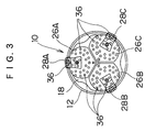
- FIG. 3 is a front view of the leading hammer
- FIG. 4 is a section view of the leading hammer along line 4 — 4 in FIG. 2;
- FIG. 5 is a side view of a rod
- FIG. 6 is a front view of the rod
- FIG. 7 is a side section view of the rod
- FIG. 8 is a section view of the rod along line 8 — 8 in FIG. 5;
- FIGS. 9 ( a )- 9 ( c ) are explanatory views for the operation of the multiple air hammer apparatus
- FIG. 10 is a side section view of a swivel device
- FIG. 11 is section view of the swivel device along line 11 — 11 in FIG. 10;
- FIG. 12 is a front view of a target
- FIGS. 13 ( a )- 13 ( e ) are explanatory views for the operation of the multiple air hammer
- FIGS. 14 ( a )- 14 ( e ) are explanatory views for the operation of the multiple air hammer.
- FIGS. 15 ( a ) and 15 ( b ) are a side view and a bottom view, respectively, of the multiple air hammer apparatus in another embodiment.
- FIG. 1 is a side view of a multiple air hammer apparatus, which comprises a leading hammer 10 and a propulsive device 40 .
- the leading hammer 10 excavates the earth and leads a casing 12 , and the propulsive device 40 provides rotation and propulsive power to the leading hammer 10 .
- the leading hammer 10 is provided with a hammer case 18 , in which three air hammers 16 A, 16 B and 16 C are housed.
- the air hammers 16 A- 16 C comprise hammer cylinders 20 A- 20 C and hammer pistons 22 A- 22 C.
- the hammer cylinders 20 A- 20 C are cylindrical, and bit chucks 24 A- 24 C are mounted at the front ends of the hammer cylinders 20 A- 20 C.
- Bits 26 A- 26 C are slidably supported at the bit chucks 24 A- 24 C.
- the hammer pistons 22 A- 22 C are slidably provided in the hammer cylinders 20 A- 20 C.
- the hammer pistons 22 A- 22 C slide in the hammer cylinders 20 A- 20 C when being driven with the air supplied from air supply pipes 3 A- 3 C, which will be described later.
- the hammer pistons 22 A- 22 C slide in the hammer cylinders 20 A- 20 C, and the back end faces of the bits 26 A- 26 C are thereby struck by the hammer pistons 22 A- 22 C.
- bits 26 A- 26 C are in the same form, and they are connected to substantially form a circle as a whole.
- Bit teeth 28 A- 28 C are provided to the bits 26 A- 26 C for extending the outer diameters of the bits 26 A- 26 C by projecting from the outer peripheries of the bits 26 A- 26 C.
- the bit teeth 28 A- 28 C are slidably provided to guide grooves 30 A- 30 C, which are respectively formed at the front ends of the bits 26 A- 26 C.
- the guide grooves 30 A- 30 C are formed radially from the center of the hammer case 18 , and they are respectively formed by inclining at a predetermined angle with respect to the axis of the hammer case 18 .
- Each of the guide grooves 30 A- 30 C and the bit teeth 28 A- 28 C is formed like a trapezoid in its section, whereby the bit teeth 28 A- 28 C are prevented from falling off the guide grooves 30 A- 30 C.
- Stopper pins (not shown) for regulating the moving range of the bit teeth 28 A- 28 C are fixed at the bit teeth 28 A- 28 C.
- the stopper pins are fitted with stopper grooves (not shown), which are formed at the guide grooves 30 A- 30 C.
- the stopper grooves are formed in a predetermined length along the guide grooves 30 A- 30 C, so that moving of the bit teeth 28 A- 28 C in the front end direction is regulated by contacting the stopper pins with the front ends of the stopper grooves.
- Moving of the bit teeth 28 A- 28 C in the back end direction is regulated by contacting back ends 28 a - 28 c of the bit teeth 28 A- 28 C with back end faces 30 a - 30 c of the guide grooves 30 A- 30 C.
- bit teeth 28 A- 28 C constructed as described above project from the outer peripheries of the bits 26 A- 26 C by moving in the back end direction (direction to the right-hand side in FIG. 2) of the leading hammer 10 , whereby the outer diameters of the bits 26 A- 26 C extend. At this moment, the front end faces of the bit teeth 28 A- 28 C are on the same plane as the front end faces of the bits 26 A- 26 C.
- bit teeth 28 A- 28 C retract from the outer peripheries of the bits 26 A- 26 C by moving in the front end direction (direction to the left-hand side in FIG. 2) of the leading hammer 10 , whereby the outer diameters of the bits 26 A- 26 C are contracted. At this moment, the outer peripheral faces of the bit teeth 28 A- 28 C are flush with the outer peripheral faces of the bits 26 A- 26 C.
- Exhaust channels 34 a - 34 c are formed at the guide grooves 30 A- 30 C of the bits 26 A- 26 C, respectively, and the air that is used for activation of the air hammers 16 A- 16 C is discharged through the exhaust channels 34 a - 34 c into an excavation hole 112 . Since the air is discharged through the exhaust channels 34 a - 34 c, the guide grooves 30 A- 30 C are prevented from being clogged by the excavated soil.
- metal chips e.g., made of cemented carbide
- 36 , 36 , . . . are fixed at the front end faces of the bits 26 A- 26 C and the bit teeth 28 A- 28 C, and the earth is struck by the metal chips 36 , 36 , . . . and excavated.
- each of the bits 26 A- 26 C inclines toward the center of the leading hammer 10 , so that the front faces of the bits 26 A- 26 C define a concave face as a whole. Because of that, when only one of the air hammers is operated or only one of the air hammers is operated harder than the others, a correction effect improves by the strike reaction force generated from the concave inclined face toward the outer periphery.
- a propulsive base 44 is horizontally provided in a starting vertical shaft 42 .
- a guide rail 46 is laid on the propulsive base 44 , and the propulsive device 40 is slidably supported on the guide rail 46 .
- the propulsive device 40 is connected with a propulsive cylinder 48 .
- the propulsive device 40 is driven by the propulsive cylinder 48 so as to slide on the guide rail 46 .
- the propulsive device 40 is connected also with a soil discharge case 50 .
- the casing 12 is supported on the front face of the soil discharge case 50 , and a rod 1 is inserted through the casing 12 .
- FIGS. 5, 6 and 7 are a side view, a front view and a side section view, respectively, of the rod 1
- FIG. 8 is a section view of the rod 1 along line 8 — 8 in FIG. 5
- the rod 1 is constructed in which the three air supply pipes 3 A, 3 B and 3 C and a water supply pipe 4 are integrally fixed around the main pipe 2 .
- the main pipe 2 is hollow, and on its peripheral face, a spiral-shaped auger wing 5 is integrally fixed.
- Flanges 6 a and 6 b for connecting the rods 1 with each other are also integrally fixed at both ends of the main pipe 2 .
- the flanges 6 a and 6 b have a plurality of bolt holes 7 , 7 , . . . for fastening the flanges with each other with bolts.
- a positioning pin 8 is projected at the flange 6 a while a pin hole (not shown) is formed at the other flange 6 b.
- the positioning pin 8 that is formed at the flange 6 a of the rod 1 is fitted with the pin hole that is formed at the flange 6 b of the other rod 1 ; thereby, the main pipes 2 , the air supply pipes 3 A, 3 B and 3 C, and the water supply pipes 4 of the rods 1 to be connected with each other are respectively positioned so as to communicate with each other.
- the three air supply pipes 3 A, 3 B and 3 C are hollow, and have the same length as the main pipe 2 .
- the three air supply pipes 3 A, 3 B and 3 C are disposed to be parallel with the main pipe 2 , and are disposed with a predetermined space to define a circle concentric with the main pipe 2 .
- the three air supply pipes 3 A, 3 B and 3 C are integrally fixed on the peripheral face of the main pipe 2 through fixing portions 3 a, 3 b and 3 c.
- the water supply pipe 4 is hollow, and has the same length as the main pipe 2 .
- the water supply pipe 4 is disposed to be parallel with the main pipe 2 , and is integrally fixed on the peripheral face of the main pipe 2 through a fixing portion 4 a.
- the rod 1 which is constructed as described above, is connected with a case rod 60 , which is formed at the back end of the hammer case 18 .
- the case rod 60 is provided at the center of the hammer case 18 , and has the same construction as the rod 1 . More specifically, an auger wing 64 is integrally fixed on the outer periphery of a hollow shaft 62 , while air supply pipes 66 A, 66 B and 66 C, which are independent from each other, and a water supply pipe are disposed around the hollow shaft 62 .
- the case rod 60 and the rod 1 are connected with each other so that their hollow shafts, the air supply pipes, and the water supply pipes are respectively connected with each other.
- a target 63 for position determination is provided which has a scale in a pattern of a grid.
- the target 63 is arranged at the center of the hammer case 18 .
- the target 63 may be provided in the hammer case 18 .
- a rod rotating device 68 is provided to the propulsive device 40 .
- the rod 1 is driven by the rod rotating device 68 so as to rotate, or to turn to and fro, successively or intermittently.
- the leading hammer 10 rotates, or turns to and fro, by the rotation or turn of the rod 1 .
- the rod rotating device 68 is provided with a rotation angle determination device by which the rotation angle of the leading hammer 10 can be determined.
- the propulsive device 40 has a swivel device 70 , which is provided with three independent passages.
- the air is supplied from a compressor 72 , which is arranged on the ground, through the swivel device 70 to the three air supply pipes 3 A, 3 B and 3 C, which are disposed at the rod 1 .
- the air that is supplied to the air supply pipes 3 A, 3 B and 3 C is further supplied to the air hammers 16 A- 16 C of the leading hammer 10 , whereby the air hammers 16 A- 16 C are activated.
- the air supply amount for each of the air hammers 16 A- 16 C is adjusted by separately controlling the opening and closing amount of each of the valves 73 X- 73 Z, which are correspondingly provided with the air hammers 16 A- 16 C.
- the opening and closing operation of each the valves 73 X- 73 Z is separately controlled by a remote-controlled operation from an operation board 104 or manual operation.
- a reference numeral 106 in FIG. 1 is assigned to a laser theodolite, which is used for measuring an inclining amount of the leading hammer 10 .
- a detailed measurement method is as presented below.
- the laser theodolite 106 emits a laser beam toward the target 63 provided to the case rod 60 .
- the laser beam is emitted from the laser theodolite 106 to be in parallel with a planned design line. If the leading hammer 10 is performing the excavation as planned, the laser beam hits the center of the target 63 . Thus, a deviation amount of the leading hammer 10 with respect to the planned design line can be determined by measuring a deviation amount of the hitting point of the laser beam on the target 63 with respect to the center of the target 63 . If the laser beam is off upward from the center of the target 63 , it is indicated that the leading hammer 10 deviates downward from the planned line.
- the display on the target 63 is transmitted via a cable communication or a radio communication by a position sensor (not shown) provided in the hollow shaft 62 , and the image is displayed on a monitor (not shown) on the operation board 104 , which is arranged on the ground.
- the operator operates the operation board 104 while looking at the image on the monitor and performs correction as required.
- a reference numeral 108 in FIG. 1 is assigned to a soil discharging device, which discharges excavated soil that is collected in the soil discharging case 50 to the ground.
- the soil that is excavated by the bits 26 A- 26 C of the leading hammer 10 is carried by the exhaust air to the casing 12 through a space between the hammer case 18 and the casing 12 .
- the excavated soil is then transported with the exhaust air to the soil discharging case 50 by the rotating rod 1 , and is discharged to the ground by the soil discharging device 108 . Since the rod 1 is provided with the auger wing 5 , the excavated soil can be efficiently discharged to the ground regardless of excavated distance.
- a reference numeral 110 in FIG. 1 is assigned to a hydraulic unit for driving the propulsive cylinder 48 and so forth, and a reference numeral 81 in FIG. 1 is an entrance packer for injecting slip additive and preventing the air leakage.
- the bits 26 A- 26 C provided at the front end of the leading hammer 10 are contacted with a working face, and the propulsive cylinder 48 of the propulsive device 40 is driven, whereby the leading hammer 10 and the casing 12 are propelled.
- the rod rotating device 68 is driven so as to rotate the rod 1 .
- the rotation of the rod 1 is transmitted to the leading hammer 10 , and the leading hammer 10 rotates.
- the compressor 72 is driven at the same time as the driving of the rod rotating device 68 , and the valves 73 X- 73 Z are opened.
- the air is supplied to the air supply pipes 3 A- 3 C of the rod 1 from the compressor 72 through a line oiler 75 , the valves 73 X- 73 Z, air pipes 74 X, 74 Y and 74 Z, and the swivel device 70 .
- the air is then supplied to the air hammers 16 A- 16 C of the leading hammer 10 , so that the air hammers 16 A- 16 C are activated. More specifically, the hammer pistons 22 A- 22 C of the air hammers 16 A- 16 C are activated and strike the bits 26 A- 26 C; thereby, the working face is repeatedly struck by the bits 26 A- 26 C and is crushed.
- bit teeth 28 A- 28 C provided to the bits 26 A- 26 C move in the direction to retreat from the front end face by contacting the working face so as to extend.
- an excavation hole 112 with a larger diameter than that of the casing 12 is excavated.
- the excavated soil that is excavated by the bits 26 A- 26 C is discharged into the casing 12 through the space between the casing 12 and the hammer case 18 by the effect of the exhaust air.
- the excavated soil that is discharged to the casing 12 is transported with the exhaust air to the soil discharging case 50 by the effect of the rotating rod 1 , and is collected from the soil discharging case 50 by the soil discharging device 108 .
- the leading hammer 10 is rotated in one direction and the respective air hammers 16 A- 16 C are uniformly activated so as to excavate the ground (see FIG. 9 ( a )).
- the excavation operation is temporally stopped, and the correct direction is confirmed from the display of the monitor.
- the above-described excavation for correction is performed by confirming the correction amount with the monitor on the operation board 104 , and the excavation is completed as the desired correction is achieved. After that, the normal excavation is resumed.
- the multiple air hammer apparatus in the present embodiment has a high energy efficiency and can easily correct the excavating direction by using the air hammers 16 A- 16 C that are separately driven and controlled.
- the correction of the excavating direction is possible for the entire 360 degrees.
- the multiple air hammer apparatus in the present embodiment has the extendable and contractible bit teeth 28 A- 28 C, which are provided to the 26 A- 26 C, respectively; thus, the leading hammer 10 can be pulled out into the vertical shaft at the starting side by contracting the bit teeth 28 A- 28 C, resulting in that the excavation can be performed regardless of the size and existence of the reaching vertical shaft.
- the apparatus can achieve correcting of the excavating direction even in a stable environment with bedrock for which the casing is unnecessary (refer to FIG. 14 ( a )).
- the bit when correcting the excavating direction, the bit is turned to and fro about the central axis of the hammer case 18 so as to excavate the earth in the correct direction; as required, however, the excavation may be performed without turning.
- the bit that is at the position corresponding with the correct direction when correcting the excavating direction, only the bit that is at the position corresponding with the correct direction is activated to excavate; however, all the bits may be used for such excavation by respectively setting the striking powers of the bits different. More specifically, the striking power of the bit that is at the position corresponding with the correct direction is made stronger than the striking power of the other bits (i.e. the activation pressure of the air hammer for the bit that is at the position corresponding with the correct direction is set higher than the others), and the excavation difference resulting from the different activation pressure is used to correct the excavating direction.
- only one bit is activated to excavate the earth when correcting the excavating direction; as required, however, the plurality of bits may be used to excavate.
- the multiple air hammer apparatus in the second embodiment controls the air supply amount to each of the air hammers with the swivel device.
- the construction of the swivel device is presented below.
- the swivel device 70 comprises an swivel device body 76 and a swivel rotating device 78 .
- the swivel device body 76 mainly comprises a case 80 and a rotating body 84 .
- the case 80 is cylindrical.
- Air supply channels 86 X, 86 Y and 86 Z are formed on the outer periphery of the case 80 with predetermined intervals.
- the air supply pipes 74 X, 74 Y and 74 Z, which are connected with the compressor 72 , are connected with the air supply channels 86 X, 86 Y and 86 Z.
- the rotating body 84 is cylindrical and is rotatably supported at the inner periphery of the case 80 via a bearing 82 .
- a flange 87 is formed at substantially the center of the rotation body 84 , and is slidably contacted with the inner periphery of the case 80 via seals 87 a and 87 a.
- Three concave portions 88 A, 88 B and 88 C, which are in an arched shape in section, are formed on the outer periphery of the flange 87 with predetermined intervals.
- the three concave portions 88 A, 88 B and 88 C define three air supply chambers 90 A, 90 B and 90 C between the inner periphery of the case 80 and themselves, and the activation air is supplied from the air supply channels 86 X, 86 Y and 86 Z to the air supply chambers 90 A, 90 B and 90 C.
- the rod 1 is connected with the front end face of the rotation body 84 , and the hollow shaft 54 of the rod 1 and the hollow portion of the rotation body 84 are connected with each other.
- the air supply pipes 3 A, 3 B and 3 C of the rod 1 communicate with the air supply chambers 90 A, 90 B and 90 C through three air supply passages 92 A, 92 B and 92 C, respectively.
- the activation air goes through the air supply passages 92 A- 92 C to the air supply pipes 3 A, 3 B and 3 C.
- the activation air is supplied to only the air supply chamber 90 A, the activation air is supplied to only the air hammer 16 A through the air supply passage 92 A and the air supply pipe 3 A, so that only the air hammer 16 A is activated.
- the rod 1 rotates at excavation.
- the rotation body 84 rotates also, and thus the air supply chambers 90 A- 90 C rotate as well. Because of that, the air is supplied to each of the air supply chambers 90 A- 90 C only when each of the air supply chambers communicates with each of the air supply channels 86 X- 86 Z.
- the activation air is supplied to one of the air supply chamber 90 A- 90 C that is communicating with the air supply channel 86 X.
- only one of the air hammers that is being arranged at the position corresponding with the direction of air supply channel 86 X is activated, and only the earth in the direction is excavated.
- the earth in the selected specific direction can be excavated.
- the swivel rotating device 78 rotates the case 80 of the swivel device body 76 so as to change positions of the air supply channels 86 X- 86 Z.
- the swivel rotating device 78 has a motor 94 , which is provided to the propulsive device 40 .
- a driving gear 96 is fixed at the output shaft of the motor 94 .
- the drive gear 96 is connected with a swivel rotation gear 98 , which is connected with the case 80 of the swivel device body 76 via a cylinder 100 .
- the rotation of the motor 94 is transmitted to the swivel rotation gear 98 through the drive gear 96 , and the case 80 thereby rotates.
- the rod 1 progresses with the swivel device 70 and the leading hammer 10 progresses.
- the swivel device 70 is constructed as presented above.
- the air supply channels 86 X- 86 Z are joined with the air supply pipes 74 X, 74 Y and 74 Z, respectively, and the air is supplied to the air supply channels 86 X- 86 Z from the compressor 72 via the air supply pipes 74 X, 74 Y and 74 Z.
- the valves 73 X, 73 Y and 73 Z are provided to the air supply pipes 74 X, 74 Y and 74 Z, respectively, and the air supply amount for each of the air hammer 16 A- 16 C is adjusted by controlling the opening and closing amount of each of the valves 73 X, 73 Y and 73 Z.
- the opening and closing of each of the valves 73 X, 73 Y and 73 Z is separately controlled by a remote-controlled operation from the operation board 104 or a manual control.
- the deviation amount of the leading hammer 10 is measured by a transit, and its measuring method is as presented below.
- a target 63 ′ is provided in the hollow shaft 62 of the case rod 60 .
- Three measurement points P 0 , P 1 and P 2 are formed in the target 63 ′, in which the measurement point P 0 is formed at the center of the hammer case 18 (that is, the center of the hollow shaft 62 ), and the measurement points P 1 and P 2 are formed on the straight line connecting the center of the hammer case 18 and the center of the air hammer 16 A with a predetermined distance.
- the transit determines the deviation amount of the leading hammer 10 by measuring the position of the three measurement points P 0 , P 1 and P 2 with respect to the planned design line.
- the position of the bit 26 A, which is struck with the air hammer 16 A can be determined by determining the positions of the measurement points P 1 and P 2 with respect to the measurement point P 0 .
- the transit is provided in the same manner as the laser theodolite 106 in the first embodiment.
- the target 63 ′ may be provided in the hammer case 18 .
- the air is supplied to the air hammers 16 A- 16 C through the air supply passages 92 A- 92 C and the air supply pipes 3 A- 3 C, and the air hammers 16 A- 16 C are activated.
- the air is supplied to each of the air supply chambers 90 A- 90 C only when each of the air supply chambers 90 A- 90 C and each of the air supply channels 86 X- 86 Z communicate with each other.
- the air supply chambers 90 A- 90 C rotate by following the rotation of the air hammers 16 A- 16 C, and each of the air supply chambers 90 A- 90 C communicates with the compressor 72 and is supplied with the air only when each of the air supply chambers 90 A- 90 C and each of the air supply channels 86 X- 86 Z communicate with each other.
- FIG. 13 ( c ) if the air supply channels 86 X- 86 Z are blocked with the outer periphery of the rotation body 84 , the air is not supplied to the air supply chambers 90 A- 90 C.
- the operation principle if only the valve 73 X is opened so as to supply the activation air to only the air supply channel 86 X, the activation air is supplied to one of the air supply chambers 90 A- 90 C that is communicating with the air supply channel 86 X.
- the opening rate of the valve 73 X is set large and that of the valves 73 Y and 73 Z is set small, only the strike in the direction of the air supply channel 86 X is made strong; consequently the apparatus can excavate the earth by providing the air hammers with striking power different from one hammer to another.
- the bits 26 A- 26 C provided at the front end of the leading hammer 10 are contacted with the working face, and the propulsive cylinder 48 of the propulsive device 40 is driven, whereby the leading hammer 10 and the casing 12 are propelled.
- the rod rotating device 68 is driven to rotate the rod 1 , whereby the rotation of the rod 1 is transmitted to the leading hammer 10 and the leading hammer 10 rotates.
- the compressor 72 is driven at the same time as the driving of the rod rotating device 68 and the valves 73 X- 73 Z are opened. Thereby, the activation air is supplied from the compressor 72 to the air supply channels 86 X- 86 Z of the swivel device body 76 through the air supply pipes 74 X- 74 Z. The air is further supplied from the air supply channels 86 X- 86 Z to the air hammers 16 A- 16 C of the leading hammer 10 through the air supply chambers 90 A- 90 C, the air supply passages 92 A- 92 C and the air supply pipes 3 A- 3 C, and the air hammers 16 A- 16 C are thus activated. More specifically, the hammer pistons 22 A- 22 C of the air hammers 16 A- 16 C are activated so as to strike the bits 26 A- 26 C, whereby the working face is repeatedly struck with the bits 26 A- 26 C and crushed.
- bit teeth 28 A- 28 C provided to the bits 26 A- 26 C move in the direction to retract from the front end face by contacting with the working face and extends.
- the excavation hole 112 with the larger diameter than that of the casing 12 is excavated.
- the soil that is excavated with the bits 26 A- 26 C is discharged into the casing 12 through the space between the casing 12 and the hammer case 18 by the effect of the exhaust air.
- the excavated soil that is now discharged to the casing 12 is transported with the exhaust air to the soil discharging case 50 by the effect of the rotating rod 1 , and is collected from the soil discharging case 50 by the soil discharging device 108 .
- the leading hammer 10 is rotated in one direction and the air hammers 16 A- 16 C are uniformly activated so as to excavate the earth.
- the fact that the leading hammer 10 deviates from the planned design line can be confirmed by determining the positions of the measurement points P 0 -P 2 of the target 63 ′ by the transit through a hollow 84 a of the swivel device body 76 as shown in FIG. 12 .
- one of the air supply channels 86 X- 86 Z is positioned in the correct direction (in this case, just upward).
- the air supply channel 86 X is turned to the just upward direction as shown in FIG. 13 ( a ). If the air supply channel 86 X is at the position in the correct direction, the operation is unnecessary.
- one of the air supply chambers 90 A- 90 C communicating with the air supply channel 86 X is successively changed. Because of that, one of the air hammers 16 A- 16 C that excavates the earth with strong striking power successively changes, and only the air hammer that positions in the just upward direction excavates the earth with strong striking power. More specifically, the excavation is performed in the following manner.
- each of the air supply chambers 90 A- 90 C has a predetermined width, the activation air with high pressure is supplied to only the air supply chamber 90 A while the air supply chamber 90 A communicates with the air supply channel 86 X as shown in FIG. 13 ( b ) even if the leading hammer 10 is rotating; as a result, only the air hammer 16 A excavates the earth in the just upward direction with the strong striking power.
- the leading hammer 10 moreover rotates and the air supply chamber 90 B comes to communicate with the air supply channel 86 X as shown in FIG. 13 ( d ), so that the activation air with high pressure is now supplied to only the air supply chamber 90 B.
- the air hammer 16 B excavates the earth with the strong striking power.
- the air hammer 16 B is positioned substantially in the just upward direction, and thus only the earth in the just upward direction is excavated with the strong striking power.
- the excavating direction of the leading hammer 10 is gradually corrected toward the just upward direction as shown in FIGS. 14 ( a )-( d ), and at last, the center of the leading hammer 10 is positioned on the planned design line as shown in FIG. 14 ( e ).
- the fact that the center of the leading hammer 10 is positioned on the planned design line can be confirmed by determining with the transit that the measurement point P 0 of the target 63 corresponds with the center of the planned line.
- the air hammers 16 A- 16 C strike the bits 26 A- 26 C, respectively, with the uniform striking power and progress straight and horizontally so as to excavate the earth.
- the multiple air hammer apparatus in the present embodiment can correct the excavating direction by the easy operation of supplying the activation air, and its correcting operation can be successively performed.
- the excavating direction can be thus corrected efficiently.
- the multiple air hammer apparatus in the present embodiment does not need special equipment like a conventional multiple air hammer apparatus with a duplicate pipe structure, with a turning device, and so forth; hence, the entire device can be compact in size.
- the case has been described where the excavating direction is corrected toward the just upward direction; if the excavating direction is corrected toward the left-hand side when viewing from the transit, the air supply channel 86 X is turned to the left-hand side.
- the motor 94 of the swivel rotating device 78 is driven so as to rotate the case 80 of the swivel device body 76 so that the air supply channel 86 X is turned to the left-hand side.
- the excavating direction can be corrected toward any direction of 360 degrees.
- an intermediate point between two of the air supply channels may be turned to the correct direction, and the air pressure of the activation air that is supplied to the two air supply channels may be set higher than the air pressure of the activation air that is supplied to the other air supply channel.
- the intermediate point between the air supply channels 86 X and 86 Y is turned to the correct direction (in this case the air supply channel 86 Z is turned in the opposite direction to the correct direction), and the air pressure of the activation air that is supplied to the air supply channels 86 X and 86 Y is set higher than the air pressure of the activation air that is supplied to the other air supply channel 86 Z.
- the activation air is supplied to the respective air supply channels 86 X- 86 Z.
- one of the air supply channels 86 X- 86 Z is turned to the position corresponding with the correct direction (for example, the just upward direction).
- the air supply channel 86 X for example, is positioned at the just upward direction.
- the activation air is supplied to only the air supply channel 86 X that has been at the position corresponding with the correct direction.
- the propulsive cylinder 48 and the rod rotating device 68 are driven so as to rotate and propel the leading hammer 10 .
- the activation air is supplied to only the air supply channel 86 X, the activation air is supplied to only one of the air supply chambers 90 A- 90 C that is communicating with the air supply channel 86 X.
- the activation air is supplied to only the air supply chamber 90 A when the air supply channel 86 X communicates with the air supply chamber 90 A; as a result, only the air hammer 16 A is activated and thus only the earth in the just upward direction is excavated by the bit 26 A.
- each of the air supply chambers 90 A- 90 C has the predetermined width, the activation air is supplied to only the air supply chamber 90 A as shown in FIG. 13 ( b ) while the air supply chamber 90 A communicates with the air supply channel 86 X even though the leading hammer 10 is rotating; consequently, only the air hammer 16 A is activated.
- the leading hammer 10 moreover rotates and the air supply channel 86 X comes to communicate with the air supply chamber 90 B as shown in FIG. 13 ( d ).
- the activation air is supplied to only the air supply chamber 90 B; and only the air hammer 16 B is thereby activated.
- the air hammer 16 B is positioned in the just upward direction, and thus only the earth in the just upward direction is excavated with the bit 26 B.
- each of the air supply chambers 90 A- 90 C has the predetermined as described above, the activation air is supplied to only the air supply chamber 90 B while the air supply chamber 90 B communicates with the air supply channel 86 X as shown in FIG. 13 ( e ) even though the leading hammer 10 is rotating; consequently, only the air hammer 16 B is activated and only the earth in the just upward direction is excavated by the air hammer 16 B.
- the apparatus of the present embodiment can easily correct the excavating direction by the easy operation for changing the supply of the activation air.
- the three air supply channels 86 X- 86 Z are formed at the case 80 of the swivel device body 76 ; however, the number of the air supply channels is not limited to three. For example, four channels may be formed at every 90 degrees, or six channels may be formed at every 60 degrees.
- the swivel device of the present invention is applied to the multiple air hammer apparatus; however, the swivel device of the present invention can be applied to another apparatus that is equipped with a plurality of excavation tools other than the air hammer.
- the swivel device of the present invention can be applied also to another apparatus using a fluid other than the air.
- the three air hammers 16 A- 16 C are provided to the leading hammer body 10 ; however, the number of the air hammers is not limited to three.
- bits 26 D- 26 F shown in FIGS. 15 ( a ) and 15 ( b ) without the extension/contraction function can be used in a case if the leading hammer body 10 does not have to be pulled out into the starting side and collected.
- the bits 26 D- 26 F have the same form, and they define a circle as a whole by joining to each other and project from the outer periphery of the casing 12 .
- the multiple air hammer apparatus and the excavating direction correcting method therefor is highly energy efficient and can easily correct the excavating direction, since the air hammers striking the bits are separately operatable.
- a fluid can be selectively supplied to only the supply pipe that is positioned in the direction of a particular supply channel by selectively supplying the fluid to the particular supply channel of the plurality of supply channels.
- the earth in the particular direction can be selectively excavated by adjusting the supply pressure of the activation air that is supplied to each of the air supply channels of the swivel device, and thus, the excavating direction can be corrected easily as well as efficiently.
- the air can be separately supplied to the respective air hammers from the plurality of air supply pipes disposed around the main pipe; thereby the respective air hammers can be separately operated.
- the excavated soil can be efficiently discharged with the auger wings which are attached around the main pipe regardless of the excavation distance.
Landscapes
- Engineering & Computer Science (AREA)
- Life Sciences & Earth Sciences (AREA)
- Mining & Mineral Resources (AREA)
- Geology (AREA)
- General Life Sciences & Earth Sciences (AREA)
- Environmental & Geological Engineering (AREA)
- Fluid Mechanics (AREA)
- Physics & Mathematics (AREA)
- Geochemistry & Mineralogy (AREA)
- Mechanical Engineering (AREA)
- Paleontology (AREA)
- Civil Engineering (AREA)
- General Engineering & Computer Science (AREA)
- Structural Engineering (AREA)
- Earth Drilling (AREA)
Applications Claiming Priority (4)
| Application Number | Priority Date | Filing Date | Title |
|---|---|---|---|
| JP34479899A JP3491681B2 (ja) | 1999-12-03 | 1999-12-03 | マルチエアハンマ装置 |
| JP11-344798 | 1999-12-03 | ||
| JP2000-328861 | 2000-10-27 | ||
| JP2000328861A JP2002129867A (ja) | 2000-10-27 | 2000-10-27 | ロッド |
Publications (2)
| Publication Number | Publication Date |
|---|---|
| US20010006120A1 US20010006120A1 (en) | 2001-07-05 |
| US6467558B2 true US6467558B2 (en) | 2002-10-22 |
Family
ID=26577866
Family Applications (1)
| Application Number | Title | Priority Date | Filing Date |
|---|---|---|---|
| US09/725,947 Expired - Lifetime US6467558B2 (en) | 1999-12-03 | 2000-11-30 | Multiple air hammer apparatus and excavating direction correcting method therefor |
Country Status (5)
| Country | Link |
|---|---|
| US (1) | US6467558B2 (zh) |
| KR (1) | KR100797594B1 (zh) |
| CN (1) | CN1305046A (zh) |
| HK (1) | HK1038782A1 (zh) |
| SG (1) | SG97991A1 (zh) |
Cited By (5)
| Publication number | Priority date | Publication date | Assignee | Title |
|---|---|---|---|---|
| US20060006001A1 (en) * | 2004-07-09 | 2006-01-12 | Cooper Cary W | Percussive reamer and method of use thereof |
| WO2006062309A1 (en) * | 2004-12-07 | 2006-06-15 | Byung-Duk Lim | A ground drilling hammer and the driving method |
| US20090294181A1 (en) * | 2008-05-29 | 2009-12-03 | Barbera James S | Box gusseted earth auger |
| CN101146978B (zh) * | 2004-12-07 | 2011-10-05 | 林秉德 | 挖掘用凿钻锤及驱动方法 |
| WO2020243767A1 (en) * | 2019-06-04 | 2020-12-10 | Paul Reed | Drilling arrangements |
Families Citing this family (16)
| Publication number | Priority date | Publication date | Assignee | Title |
|---|---|---|---|---|
| EP1300543A1 (de) * | 2001-10-08 | 2003-04-09 | Günter W. Prof. Dr. Klemm | Erweiterungsbohrsystem |
| AT501696B1 (de) * | 2004-03-30 | 2008-03-15 | Alwag Tunnelausbau Gmbh | Verfahren und vorrichtung zum bohren von löchern in boden- oder gesteinsmaterial |
| CA2784979C (en) * | 2009-12-22 | 2015-02-03 | Hanjin D&B Co.,Ltd. | Air hammer for a boring machine |
| CN101871222B (zh) * | 2010-06-21 | 2012-02-29 | 北京市三一重机有限公司 | 旋挖钻机桅杆油缸运动控制方法及系统 |
| HK1156182A2 (en) * | 2011-02-11 | 2012-06-01 | Top Mark Mechanical Equipment Ltd | Annulus ring hole drill |
| HK1155608A2 (en) * | 2012-02-10 | 2012-05-18 | Top Mark Mechanical Equipment Ltd | Method and apparatus for controlling the operation of cluster drill of down-the-hole hammers |
| US9175517B2 (en) | 2012-02-10 | 2015-11-03 | Top Mark Mechanical Equipment Limited | Method and apparatus for controlling the operation of cluster drill of down-the-hole hammers |
| JP6225037B2 (ja) | 2014-01-23 | 2017-11-01 | 三菱日立パワーシステムズ株式会社 | 管の製造方法及び管 |
| US9657521B2 (en) * | 2014-06-02 | 2017-05-23 | King Fahd University Of Petroleum And Minerals | Directional system drilling and method |
| KR101652991B1 (ko) * | 2015-03-26 | 2016-09-09 | 한국생산기술연구원 | 암분 배출이 효과적으로 이루어지는 dth 방식의 천공기 및, 이를 이용한 천공방법 |
| EP3333356B1 (de) * | 2016-12-07 | 2020-01-29 | BAUER Maschinen GmbH | Drehbohrwerkzeug und verfahren zum erstellen einer bohrung im boden |
| CN107165574B (zh) * | 2017-07-13 | 2019-01-11 | 西南石油大学 | 一种冲锤式冲击螺杆钻具 |
| JP2019124009A (ja) * | 2018-01-12 | 2019-07-25 | 大智株式会社 | 掘削装置、回転式掘削機、掘削方法および掘削ビット |
| US10626679B2 (en) * | 2018-03-29 | 2020-04-21 | Hard Rock Horizontal Directional Drilling Products, Inc. | Bidirectional cluster hammer reamer |
| CN109209221B (zh) * | 2018-11-14 | 2024-02-09 | 中国铁建重工集团股份有限公司 | 一种潜孔锤设备及其冲击导向系统 |
| CN114197443B (zh) * | 2021-12-29 | 2023-05-26 | 青岛地质工程勘察院(青岛地质勘查开发局) | 一种软土地基处理装置 |
Citations (7)
| Publication number | Priority date | Publication date | Assignee | Title |
|---|---|---|---|---|
| US3682258A (en) * | 1970-06-22 | 1972-08-08 | Hughes Tool Co | Rotary-percussion gang drill with circumferentially floating offset bits |
| CH613491A5 (en) * | 1977-08-24 | 1979-09-28 | Albert Rombaldi | Drilling device |
| US4878547A (en) * | 1988-10-28 | 1989-11-07 | Ingersoll-Rand Company | Rock drilling apparatus |
| JPH0345195A (ja) | 1989-07-12 | 1991-02-26 | Canon Inc | ステッピングモータの制御装置 |
| JPH03151492A (ja) * | 1989-11-08 | 1991-06-27 | Tone Boring Co | 空圧打撃掘削機のシール構造 |
| US5386878A (en) * | 1994-04-29 | 1995-02-07 | Uti Energy Corp. | Rock boring process and apparatus |
| US5735358A (en) * | 1996-06-06 | 1998-04-07 | Ingersoll-Rand Company | Indexing percussive drilling bit |
Family Cites Families (4)
| Publication number | Priority date | Publication date | Assignee | Title |
|---|---|---|---|---|
| JP3151492B2 (ja) * | 1991-03-08 | 2001-04-03 | 光洋精工株式会社 | スライド装置 |
| SE468443B (sv) * | 1991-05-30 | 1993-01-18 | Uniroc Ab | Spolkanalanordning vid slaaende maskiner foer borrning |
| JPH0941856A (ja) * | 1995-07-28 | 1997-02-10 | Tone Corp | エアハンマ掘削工法並びに装置 |
| AU3719300A (en) * | 1999-03-03 | 2000-10-04 | Earth Tool Company, Llc | Method and apparatus for directional boring |
-
2000
- 2000-11-29 SG SG200007074A patent/SG97991A1/en unknown
- 2000-11-30 US US09/725,947 patent/US6467558B2/en not_active Expired - Lifetime
- 2000-12-01 CN CN00135082A patent/CN1305046A/zh active Pending
- 2000-12-02 KR KR1020000072762A patent/KR100797594B1/ko active IP Right Grant
-
2002
- 2002-01-02 HK HK02100010.4A patent/HK1038782A1/zh unknown
Patent Citations (7)
| Publication number | Priority date | Publication date | Assignee | Title |
|---|---|---|---|---|
| US3682258A (en) * | 1970-06-22 | 1972-08-08 | Hughes Tool Co | Rotary-percussion gang drill with circumferentially floating offset bits |
| CH613491A5 (en) * | 1977-08-24 | 1979-09-28 | Albert Rombaldi | Drilling device |
| US4878547A (en) * | 1988-10-28 | 1989-11-07 | Ingersoll-Rand Company | Rock drilling apparatus |
| JPH0345195A (ja) | 1989-07-12 | 1991-02-26 | Canon Inc | ステッピングモータの制御装置 |
| JPH03151492A (ja) * | 1989-11-08 | 1991-06-27 | Tone Boring Co | 空圧打撃掘削機のシール構造 |
| US5386878A (en) * | 1994-04-29 | 1995-02-07 | Uti Energy Corp. | Rock boring process and apparatus |
| US5735358A (en) * | 1996-06-06 | 1998-04-07 | Ingersoll-Rand Company | Indexing percussive drilling bit |
Cited By (7)
| Publication number | Priority date | Publication date | Assignee | Title |
|---|---|---|---|---|
| US20060006001A1 (en) * | 2004-07-09 | 2006-01-12 | Cooper Cary W | Percussive reamer and method of use thereof |
| US7168509B2 (en) | 2004-07-09 | 2007-01-30 | Cooper Cary W | Percussive reamer and method of use thereof |
| WO2006062309A1 (en) * | 2004-12-07 | 2006-06-15 | Byung-Duk Lim | A ground drilling hammer and the driving method |
| CN101146978B (zh) * | 2004-12-07 | 2011-10-05 | 林秉德 | 挖掘用凿钻锤及驱动方法 |
| US20090294181A1 (en) * | 2008-05-29 | 2009-12-03 | Barbera James S | Box gusseted earth auger |
| US7748479B2 (en) * | 2008-05-29 | 2010-07-06 | Barbera James S | Box gusseted earth auger |
| WO2020243767A1 (en) * | 2019-06-04 | 2020-12-10 | Paul Reed | Drilling arrangements |
Also Published As
| Publication number | Publication date |
|---|---|
| HK1038782A1 (zh) | 2002-03-28 |
| KR100797594B1 (ko) | 2008-01-28 |
| CN1305046A (zh) | 2001-07-25 |
| KR20010062100A (ko) | 2001-07-07 |
| SG97991A1 (en) | 2003-08-20 |
| US20010006120A1 (en) | 2001-07-05 |
Similar Documents
| Publication | Publication Date | Title |
|---|---|---|
| US6467558B2 (en) | Multiple air hammer apparatus and excavating direction correcting method therefor | |
| US5803187A (en) | Rotary-percussion drill apparatus and method | |
| JPH1030392A (ja) | 指向性ボーリング法及び装置 | |
| JPH0384193A (ja) | 地中掘削のための方法及び装置 | |
| JP4878990B2 (ja) | 掘進機およびこれを用いた掘進装置 | |
| JPH03290585A (ja) | 方向制御形クラスタダウンホールドリル掘さく機 | |
| US6516902B1 (en) | Directional drilling system | |
| JP4184233B2 (ja) | 地盤改良体造成工法およびその装置 | |
| JPH11148298A (ja) | ボーリング等用の削進装置及び方法 | |
| JP2909014B2 (ja) | 土砂層と岩盤とを削孔する方法及び土砂層と岩盤とを削孔する装置 | |
| JP2002129867A (ja) | ロッド | |
| JPH0941856A (ja) | エアハンマ掘削工法並びに装置 | |
| JP3491681B2 (ja) | マルチエアハンマ装置 | |
| JP2001003669A (ja) | マルチエアハンマ装置及びその掘削方向修正方法 | |
| KR102376671B1 (ko) | 고수압 타격 tbm 터널 굴착 장치 | |
| JPH08277691A (ja) | 掘削工具 | |
| KR100447872B1 (ko) | 비배토식 강관 수평압입공법의 강관압입장치 | |
| JP2006045773A (ja) | 地中推進装置 | |
| JPH041398A (ja) | 小口径管路掘進用先導筒体とこれによる小口径管路掘進工法 | |
| JPH1136784A (ja) | 空圧打撃式推進装置 | |
| JPH11229775A (ja) | トンネルボーリングマシンおよびトンネル掘進における支保方法 | |
| JPH01137094A (ja) | トンネル等の掘削工法とこれに用いる注入装置 | |
| JPH0738461Y2 (ja) | 掘削用発破穴削孔機 | |
| JP2551085Y2 (ja) | 管埋設装置 | |
| JP2531513B2 (ja) | 掘進装置 |
Legal Events
| Date | Code | Title | Description |
|---|---|---|---|
| AS | Assignment |
Owner name: TONE CORPORATION, JAPAN Free format text: ASSIGNMENT OF ASSIGNORS INTEREST;ASSIGNORS:MIYAMOTO, OSAMU;AKIYAMA, YOSHIO;WATANABE, TARO;REEL/FRAME:011574/0771 Effective date: 20010117 |
|
| STCF | Information on status: patent grant |
Free format text: PATENTED CASE |
|
| AS | Assignment |
Owner name: TOA-TONE BORING CO., LTD., JAPAN Free format text: ASSIGNMENT OF ASSIGNORS INTEREST;ASSIGNOR:TONE CORPORATION;REEL/FRAME:016945/0066 Effective date: 20051003 |
|
| FPAY | Fee payment |
Year of fee payment: 4 |
|
| FPAY | Fee payment |
Year of fee payment: 8 |
|
| FPAY | Fee payment |
Year of fee payment: 12 |