US10626679B2 - Bidirectional cluster hammer reamer - Google Patents
Bidirectional cluster hammer reamer Download PDFInfo
- Publication number
- US10626679B2 US10626679B2 US15/939,982 US201815939982A US10626679B2 US 10626679 B2 US10626679 B2 US 10626679B2 US 201815939982 A US201815939982 A US 201815939982A US 10626679 B2 US10626679 B2 US 10626679B2
- Authority
- US
- United States
- Prior art keywords
- drive rod
- bidirectional
- central drive
- hammer
- drill string
- Prior art date
- Legal status (The legal status is an assumption and is not a legal conclusion. Google has not performed a legal analysis and makes no representation as to the accuracy of the status listed.)
- Active, expires
Links
- 230000002457 bidirectional effect Effects 0.000 title claims abstract description 43
- 239000012530 fluid Substances 0.000 claims abstract description 28
- 238000009527 percussion Methods 0.000 claims description 37
- 239000000758 substrate Substances 0.000 claims description 22
- 230000001737 promoting effect Effects 0.000 claims description 2
- 230000008878 coupling Effects 0.000 claims 1
- 238000010168 coupling process Methods 0.000 claims 1
- 238000005859 coupling reaction Methods 0.000 claims 1
- 238000005553 drilling Methods 0.000 abstract description 31
- 238000000034 method Methods 0.000 description 13
- 238000005259 measurement Methods 0.000 description 8
- 239000000047 product Substances 0.000 description 6
- 238000005520 cutting process Methods 0.000 description 5
- 230000008901 benefit Effects 0.000 description 4
- 239000002245 particle Substances 0.000 description 3
- 241001526284 Percus <genus> Species 0.000 description 2
- 235000009508 confectionery Nutrition 0.000 description 2
- 238000013019 agitation Methods 0.000 description 1
- 230000000712 assembly Effects 0.000 description 1
- 238000000429 assembly Methods 0.000 description 1
- 229910000278 bentonite Inorganic materials 0.000 description 1
- 239000000440 bentonite Substances 0.000 description 1
- SVPXDRXYRYOSEX-UHFFFAOYSA-N bentoquatam Chemical compound O.O=[Si]=O.O=[Al]O[Al]=O SVPXDRXYRYOSEX-UHFFFAOYSA-N 0.000 description 1
- 230000001143 conditioned effect Effects 0.000 description 1
- 230000003750 conditioning effect Effects 0.000 description 1
- 230000001627 detrimental effect Effects 0.000 description 1
- 230000007613 environmental effect Effects 0.000 description 1
- 239000000835 fiber Substances 0.000 description 1
- 238000009434 installation Methods 0.000 description 1
- 239000007788 liquid Substances 0.000 description 1
- 230000001050 lubricating effect Effects 0.000 description 1
- 238000012423 maintenance Methods 0.000 description 1
- 239000000203 mixture Substances 0.000 description 1
- 238000004064 recycling Methods 0.000 description 1
- 239000011435 rock Substances 0.000 description 1
- 239000013589 supplement Substances 0.000 description 1
- 239000000725 suspension Substances 0.000 description 1
- XLYOFNOQVPJJNP-UHFFFAOYSA-N water Substances O XLYOFNOQVPJJNP-UHFFFAOYSA-N 0.000 description 1
- 238000004804 winding Methods 0.000 description 1
Images


Classifications
-
- E—FIXED CONSTRUCTIONS
- E21—EARTH DRILLING; MINING
- E21B—EARTH DRILLING, e.g. DEEP DRILLING; OBTAINING OIL, GAS, WATER, SOLUBLE OR MELTABLE MATERIALS OR A SLURRY OF MINERALS FROM WELLS
- E21B1/00—Percussion drilling
- E21B1/12—Percussion drilling with a reciprocating impulse member
- E21B1/24—Percussion drilling with a reciprocating impulse member the impulse member being a piston driven directly by fluid pressure
- E21B1/30—Percussion drilling with a reciprocating impulse member the impulse member being a piston driven directly by fluid pressure by air, steam or gas pressure
-
- E—FIXED CONSTRUCTIONS
- E21—EARTH DRILLING; MINING
- E21B—EARTH DRILLING, e.g. DEEP DRILLING; OBTAINING OIL, GAS, WATER, SOLUBLE OR MELTABLE MATERIALS OR A SLURRY OF MINERALS FROM WELLS
- E21B10/00—Drill bits
- E21B10/26—Drill bits with leading portion, i.e. drill bits with a pilot cutter; Drill bits for enlarging the borehole, e.g. reamers
- E21B10/28—Drill bits with leading portion, i.e. drill bits with a pilot cutter; Drill bits for enlarging the borehole, e.g. reamers with non-expansible roller cutters
-
- E—FIXED CONSTRUCTIONS
- E21—EARTH DRILLING; MINING
- E21B—EARTH DRILLING, e.g. DEEP DRILLING; OBTAINING OIL, GAS, WATER, SOLUBLE OR MELTABLE MATERIALS OR A SLURRY OF MINERALS FROM WELLS
- E21B4/00—Drives for drilling, used in the borehole
- E21B4/06—Down-hole impacting means, e.g. hammers
-
- E—FIXED CONSTRUCTIONS
- E21—EARTH DRILLING; MINING
- E21B—EARTH DRILLING, e.g. DEEP DRILLING; OBTAINING OIL, GAS, WATER, SOLUBLE OR MELTABLE MATERIALS OR A SLURRY OF MINERALS FROM WELLS
- E21B1/00—Percussion drilling
-
- E—FIXED CONSTRUCTIONS
- E21—EARTH DRILLING; MINING
- E21B—EARTH DRILLING, e.g. DEEP DRILLING; OBTAINING OIL, GAS, WATER, SOLUBLE OR MELTABLE MATERIALS OR A SLURRY OF MINERALS FROM WELLS
- E21B10/00—Drill bits
- E21B10/26—Drill bits with leading portion, i.e. drill bits with a pilot cutter; Drill bits for enlarging the borehole, e.g. reamers
-
- E—FIXED CONSTRUCTIONS
- E21—EARTH DRILLING; MINING
- E21B—EARTH DRILLING, e.g. DEEP DRILLING; OBTAINING OIL, GAS, WATER, SOLUBLE OR MELTABLE MATERIALS OR A SLURRY OF MINERALS FROM WELLS
- E21B10/00—Drill bits
- E21B10/36—Percussion drill bits
-
- E—FIXED CONSTRUCTIONS
- E21—EARTH DRILLING; MINING
- E21B—EARTH DRILLING, e.g. DEEP DRILLING; OBTAINING OIL, GAS, WATER, SOLUBLE OR MELTABLE MATERIALS OR A SLURRY OF MINERALS FROM WELLS
- E21B10/00—Drill bits
- E21B10/36—Percussion drill bits
- E21B10/38—Percussion drill bits characterised by conduits or nozzles for drilling fluids
-
- E—FIXED CONSTRUCTIONS
- E21—EARTH DRILLING; MINING
- E21B—EARTH DRILLING, e.g. DEEP DRILLING; OBTAINING OIL, GAS, WATER, SOLUBLE OR MELTABLE MATERIALS OR A SLURRY OF MINERALS FROM WELLS
- E21B7/00—Special methods or apparatus for drilling
- E21B7/04—Directional drilling
- E21B7/046—Directional drilling horizontal drilling
-
- E—FIXED CONSTRUCTIONS
- E21—EARTH DRILLING; MINING
- E21B—EARTH DRILLING, e.g. DEEP DRILLING; OBTAINING OIL, GAS, WATER, SOLUBLE OR MELTABLE MATERIALS OR A SLURRY OF MINERALS FROM WELLS
- E21B7/00—Special methods or apparatus for drilling
- E21B7/28—Enlarging drilled holes, e.g. by counterboring
Definitions
- the present disclosure relates to a percussion boring system and, more particularly, to an improved leading end assembly for a percussion boring system in the form of a bidirectional cluster hammer reamer (“BCHR”).
- BCHR bidirectional cluster hammer reamer
- horizontal directional drilling systems are capable of directionally boring a winding channel in a substrate. These channels are commonly bored for any number of purposes such as for holding a product in the form of a conductive conduit, a fiber optic cable, a stretch of tubing, a sewer pipe, etc.
- Percussion boring a subterranean channel for holding a product usually begins by boring a pilot channel in a substrate along a substantially predetermined path.
- the pilot channel has an entry point, where the leading end of the horizontal directional drilling system initially enters the substrate, and an exit point where the leading end of the system eventually emerges from the substrate.
- a series of passes back and forth through the channel may be made to expand the channel size and condition its walls in anticipation of installing the product on the final pass.
- a pilot bore is expanded by either 1) retracting a reaming device and/or 2) pushing a relatively larger percussion bit.
- Reaming devices known in the art are relatively simple in design and application—at the exit point of the pilot channel, the percussive bit used to drill the pilot channel is replaced with a slightly larger reaming device that is simply dragged back through the pilot channel when the drill string is retracted.
- reamers work well to expand and condition a pilot channel.
- the advantage of reamers known in the art is that they can be pulled through a pilot channel by a retracted drill string, thereby alleviating any requirement for steering by the operator.
- the disadvantage of reamers known in the art is that they are limited in the amount of channel expansion they can provide per pass.
- percussive devices may provide for a relative increase in the amount of bore expansion that may be realized over a single pass when compared to a reamer.
- percussive devices used to expand the pilot channel are really just relatively bigger percussive bits capable of powering through rock and dirt.
- the disadvantage of using a percussive device for pilot channel expansion is that the operator must take care to stay on the path of the pilot channel and not inadvertently bore off course. As one of ordinary skill in the art would understand, reaming devices stay on course by virtue of being pulled back through the channel, but percussive devices known in the art must be steered as they are “pushed” through the channel.
- a bidirectional cluster hammer reamer for use in a horizontal direction drilling system. More specifically, one exemplary embodiment of a bidirectional cluster hammer reamer comprises a hammer housing defining a front end and a rear end of the bidirectional cluster hammer reamer with a central drive rod positioned coaxially within the hammer housing.
- the central drive rod comprises a forward string connector and a rear string connector for mechanically engaging a forward drill string and a rear drill string of the horizontal direction drilling system.
- a plurality of percussion hammers is arranged within the hammer housing and around the central drive rod.
- the hammer housing further comprises one or more support plates configured to slidably engage the central drive rod and mechanically support the plurality of percussion hammers.
- a plurality of bits are positioned at the front end of the hammer housing, each bit slidably connected via a chuck component to an associated one of the plurality of percussion hammers.
- At the rear end of the hammer housing is an air distribution assembly comprised of a plurality of plates defining a series of flow paths. Pressurized fluid supplied through the central drive rod (from the drill string) is directed through the air distribution assembly flow paths to provide a motive force for promoting a percussive cycle in each of the plurality of percussion hammers.
- a bidirectional cluster hammer reamer may comprise four to six percussion hammers, although the scope of a bidirectional cluster hammer reamer is not limited to having just four to six percussion hammers.
- the central drive rod may include one or more cutout areas on its surface and be configured to translate between a forward most position and a rear most position within the bidirectional cluster hammer reamer. When the central drive rod is in the forward most position the cutout areas cooperate with the air distribution assembly to supply the pressurized fluid to the plurality of percussion hammers. And, when the central drive rod is in the rear most position the cutout areas cooperate with the air distribution assembly to supply the pressurized fluid to the exterior of the bidirectional cluster hammer reamer.
- the cutout areas cooperate with the air distribution assembly to supply a first portion of the pressurized fluid to the plurality of percussion hammers and a second portion of the pressurized fluid to the exterior of the bidirectional cluster hammer reamer.
- FIGS. 1-3 illustrate the basic percussive cycle of a hammer in a horizontal directional drilling (“HDD”) boring arrangement
- FIG. 4 illustrates certain common exemplary embodiments of HDD systems having a bent sub
- FIGS. 5A-5B illustrate assembled and exploded views, respectively, of an exemplary bidirectional cluster hammer reamer (“BCHR”) according to an embodiment of the solution;
- FIG. 6 illustrates an exemplary splined bit segment that may be driven by a hammer comprised within an exemplary bidirectional cluster hammer reamer (“BCHR”) such as, but not limited to, the BCHR of FIG. 5 ;
- BCHR bidirectional cluster hammer reamer
- FIG. 7 illustrates a cross-sectional view of the exemplary bidirectional cluster hammer reamer (“BCHR”) of FIG. 5 , shown in a “pull” state;
- FIG. 8 illustrates a cross-sectional view of the exemplary bidirectional cluster hammer reamer (“BCHR”) of FIG. 5 , shown in a “push” state;
- FIG. 9A illustrates a close-up view of the internal air flow path through the air distribution plate assembly of the exemplary bidirectional cluster hammer reamer (“BCHR”) of FIG. 5 when it is in a “pull” state such as depicted in FIG. 7 ; and
- FIG. 9B illustrates a close-up view of the internal air flow path through the air distribution plate assembly of the exemplary bidirectional cluster hammer reamer (“BCHR”) of FIG. 5 when it is in a “push” state such as depicted in FIG. 8 .
- BCHR bidirectional cluster hammer reamer
- Certain embodiments and aspects of the present description provide a bidirectional cluster hammer reamer for a horizontal directional drilling system, the bidirectional cluster hammer reamer configured to expand a pilot hole previously drilled along a predefined subterranean path by a horizontal directional drilling system.
- horizontal directional drilling (“HDD”) is the practice of drilling non-vertical, non-linear bores.
- a common application for HDD is for the installation of utility products such as underground wiring, small bore piping, cable bundles, and the like.
- HDD applications generally require relatively accurate boring
- certain HDD applications require a particularly high degree of accuracy such as, for example, a “sewer grade” bore which will be used to accommodate sewer piping.
- a sewer grade bore must typically have less than 0.5% deviation from the predetermined path over a 300 foot run.
- the HDD process typically begins with drilling a pilot bore along a desired underground path.
- the pilot bore is enlarged to a desired diameter and its walls conditioned by pulling a larger cutting tool, sometimes termed a “reamer” or “back reamer,” back through the pilot hole.
- the product is installed in the enlarged hole by way of being pulled behind the reamer as the drill string is retracted from the reamed bore.
- embodiments of the present solution are employed during the steps of enlarging the pilot bore and, as such, may be used in lieu of, or in preference to, a typical back reamer that is understood in the art.
- HDD percussion boring when drilling a pilot bore the drill string is pushing forward, thereby facilitating a percussion cycle with a hammer component and a slidably engaged drill bit on the leading end of the drill string.
- the hammer in an HDD drill string of this sort is not able to “run on cushion,” meaning that the reciprocation of the hammer will cease upon retraction of the drill string due to a resulting “open blow” alignment of internal air passages. That is, when an HDD leading end assembly includes a hammer and a slidably engaged drill bit, the hammer cannot percuss and strike the drill bit when the drill string is being retracted in a direction opposite to the forward orientation of the hammer.
- embodiments of the present solution leverage a plurality of hammer/drill bit assemblies in a single device that may be either “pushed” or “pulled” through a previously drilled pilot bore such that the percussive cycles of the hammers are promoted.
- the drill bit of an HDD drill string engages with the substrate to be bored and works to erode the substrate at the point of engagement during the percussion boring process.
- the at least one exhaust port of the bit may be configured to expel a fluid, either drilling fluid, compressed air or any other fluid known to a person having ordinary skill in the art, such that any eroded substrate at the point of engagement is cleared away from the drill bit assembly. This prevents the drill bit assembly from becoming clogged, which can restrict any necessary freedom of movement between the component parts. This also facilitates the circulation of the drilling fluid in the channel (I.e., the pilot bore), which cools the moving parts of the drill string. This also facilitates the removal of previously eroded substrate from the channel as the percussion boring process continues.
- Drilling fluid may be compressed air, a viscous liquid mixture of water and bentonite, or any other similar combination known to a person having ordinary skill in the art.
- the drilling fluid is typically continuously pumped to the drill bit and expelled from ports in the drill bit.
- the drilling fluid may be useful for holding eroded substrate particles in suspension and lubricating the bored channel for the drill string and/or the pulled product.
- these properties of the drilling fluid help stabilize the channel walls, cool the drill bit, alleviate the pressure on the drill bit and prevent a building-up of substrate particles at the drill bit during the boring process.
- the drilling fluid may be recycled throughout the boring process by a reclaimer that circulates the drilling fluid expelled from the drill bit back through the channel and back through the drill string.
- the reclaimer may additionally remove the substrate particles from the drilling fluid and regulate/maintain the drilling fluid's ideal viscosity.
- FIGS. 1-3 illustrate the percussive cycle delivered by a piston 10 to the impact surface 21 of a drill bit 20 in an HDD drill string configured for boring.
- the drill string may be envisioned as providing a feed force from left to right. As one of ordinary skill in the art would understand, as the feed force is applied to the exemplary HDD boring arrangement illustrated in FIGS.
- the percussive cycle of the hammer piston 10 is promoted, thereby repeatedly delivering blows to the impact surface 21 of a slidably engaged drill bit 20 .
- the drill string may provide mechanical rotation, hydraulic fluid, electric signals, etc.
- a portion of a leading end assembly of an HDD drill string includes, generally, a hammer 1 containing an air distributer 3 , an inner cylinder 5 and a piston 10 .
- a drill bit 20 Also shown in the FIG. 1 illustration is a drill bit 20 .
- the drill bit 20 has a splined shaft and is slidably engaged with the hammer 1 via a chuck 35 .
- the arrows indicate air flow from an air supply (or other fluid supply) delivered to the air distributor 3 from the drill string, as would be understood by one of ordinary skill in the art.
- the air is distributed radially through a series of holes positioned circumferentially around the air distributor 3 . As the air radially exits the holes of the air distributor 3 , the air passes along the outer surface of the inner cylinder 5 in the hammer component 1 and toward the leading end of the drill string where the slidably engaged drill bit 20 is located.
- the air continues along the outer surface of the inner cylinder 5 and passes down through a series of ports 4 on the lower end of the inner cylinder 5 . After passing down through the series of ports 4 on the lower end of the inner cylinder 5 , the air continues along the outer surface of a piston 10 that is slidably engaged within the inner annular area of the inner cylinder 5 .
- the air acts on and applies a force to an upper ledge(s) 11 and various “cut out” areas 12 in the piston 10 , thereby causing the piston 10 to begin advancing forward (to the right in the illustration) relative to the inner cylinder 5 .
- the air continues to exert a greater and greater force on the upper ledge(s) 11 and the various “cut out” areas 12 in the piston 10 as it builds in pressure (the “thicker” arrows in the illustration represent forces that are relatively greater than the “thinner” arrows).
- air pressure is beginning to build up on a lower ledge 13 of the piston 10 and exerting a force back toward the inner cylinder 5 .
- the blow tube 15 can be seen in the FIG. 1 illustration, as it begins to engage into a central air passageway through the center of the piston 10 .
- blow tube 15 The air supply through the blow tube 15 ultimately exits out through the drill bit 20 and assists in the boring process. Notably, if the drill bit 20 is advanced far enough ahead of the piston 10 stroke range (such as when the drill string is being retracted relative to the boring direction), the blow tube 15 may be exposed and any air supply that would have otherwise contributed to the percussive cycle is provided with an escape route (“open blow” arrangement), as would be understood by one of ordinary skill in the art.
- the piston 10 has advanced forward enough that a percussive blow has been delivered to the impact surface 21 of the drill bit 20 . And so, the continued supply of air pressure from the distributor 3 has begun to accumulate on the lower ledge 13 of the piston 10 and is exerting a relatively large force back toward the inner cylinder 5 .
- the position of the drill bit 20 (the head 25 of the drill bit 20 is the “business end” of the drill bit that is hammered into the subterranean earth to create a pilot bore) can be seen relative to the chuck 35 when the piston 10 is in contact with impact surface 21 of the drill bit 20 .
- the gap 30 represents the “sweet spot” of the bit relative to the piston stroke range. If the drill bit 20 were advanced further to the right, the impact surface 21 of the bit 20 would be too far away from the piston 10 to receive a useful percussive blow or the percussive cycle would be interrupted. Moreover, if the bit 20 were advanced to the left such that the gap 30 is significantly reduced, the impact surface 21 of the bit 20 would be too close to the piston 10 such that the percussive blows would be detrimental to the drill string or the percussive cycle would be interrupted. As a result, in a boring configuration the drill bit 20 finds that position represented by gap 30 where the percussive cycle is urged and the piston 10 can deliver continuous blows.
- the piston 10 has retracted to the other end of its stroke range and air pressure is starting to build up as described above relative to the FIG. 1 illustration.
- the piston 10 will start to advance toward the drill bit 20 to deliver its next percussive blow to the impact surface 21 , after which the advancement of the drill string will work to maintain gap 30 .
- the percussive cycle continues. Notably, it can be seen in FIG. 3 that even though the piston 10 has retracted to its left-most position in its stroke range, the gap 30 is maintained for the reasons described above.
- the percussive cycle will repeat and percussive blows to the impact surface will be continually delivered.
- FIG. 4 illustrates certain common exemplary embodiments of percussion boring systems known to a person having ordinary skill in the art.
- a typical HDD percussion boring system comprises a drill string (not shown) and a common leading end assembly 400 .
- the common leading end assembly 400 is typical of a leading end assembly that may be employed by those of ordinary skill in the art to drill a pilot bore or pilot channel.
- embodiments of the solution may comprise an arrangement of what amounts to multiple of the components 100 (hammer/bit combinations) seen in the common leading end assembly 400 .
- the common leading end assembly 400 typically comprises the components 100 described in the FIGS. 1-3 illustration in addition to certain other components including a sonde housing 410 and a bent sub 415 .
- a common leading end assembly 400 may be configured to detachably and functionally couple, directly or indirectly, to the drill string via a threaded connection 405 on the backend of the sonde 410 .
- the sonde assembly 410 may house a sub-assembly of various instrumentation and transmitters for measuring and relaying various environmental conditions (e.g., the relative position of the leading end assembly in the substrate, the rotational orientation of the leading end assembly in the channel, and the thermal and pressure conditions in the channel).
- various environmental conditions e.g., the relative position of the leading end assembly in the substrate, the rotational orientation of the leading end assembly in the channel, and the thermal and pressure conditions in the channel.
- the bent sub 415 may be coupled via a threaded connection on the leading end of the sonde 410 .
- the bent sub 415 provides an angle or bend in the common leading end assembly 400 that allows an operator to “steer” the drill string along a subterranean path that may include one or more turns.
- the entire drill string may be rotating while the drill bit percusses (as described above). But, when the pilot bore must take a turn in the subterranean path, rotation of the drill string may be stopped so that the bent sub 415 is positioned to urge a turn. With the bent sub 415 “clocked” to a certain position in the pilot bore, and rotation of the string stopped, advancement of the string while the bit 20 percusses will cause the pilot bore to make a turn, as would be understood by one of ordinary skill in the art.
- the sonde 410 may be configured to house instrumentation that transmits measurement data to a percussion boring system operator at the surface, as would be understood by a person having ordinary skill in the art.
- the transmitted measurement data may be encoded into an electro-magnetic signal and transmitted, regardless of its encoding form, through the substrate, directly or indirectly, to the percussion boring system operator.
- the measurement data may be useful for determining whether the drill string should be elongated, redirected, or retracted.
- the measurement data may also be useful for determining the extension length and, ultimately, the amount of pressure that should be applied to the drill string as it is forced into the substrate.
- the measurement data may be further useful for: determining the rotations per minute of the drill string; adjusting the rotational orientation of the common leading end assembly in the channel; adjusting the hydraulic pressure of the drilling fluid in the drill string; and controlling the circulation of the drilling fluid in the channel.
- the measurement data gathered and transmitted by the common sonde assembly 410 may also be useful and functional for controlling the relative position of the common leading end assembly, in the substrate, and the direction towards which the common leading end assembly bores.
- a “walk-over” locating system is configured to obtain measurement data from the common sonde 410 , and/or locate the common leading end assembly 400 through its own sensors. Once the transmitted measurement data is received it may be decoded and/or relayed to the percussion boring system operator.
- an exemplary embodiment of a bent sub 415 may be bent at an angle relative to the drill string such that the remaining components 100 of the common leading end assembly 400 , below the bent sub 410 , is also at angle relative to the drill string (see angle theta “ ⁇ ” in the FIG. 4 illustration).
- the result as is understood by a person having ordinary skill in the art, is a percussion boring system with a common leading end assembly 400 that includes a portion 100 that is slightly bent to one direction relative to the associated drill string.
- the specific bend angle of the bent sub 415 may be application specific.
- a bent sub 415 comprises a bend angle range of substantially between 1.0°-3.0° relative to the longitudinal axis of the drill string substantially proximate to the common leading end assembly 400 .
- the bent sub 415 and the common sonde 410 are situated relative to one another such that locating the common sonde 410 , as described above, allows for an inference of the direction, in the channel, towards which the components 100 of the common leading end assembly 400 is bent.
- the percussion boring system to which the bent sub 415 and the common sonde 410 pertain is configured such that any adjustment of the rotational orientation of the common leading end assembly 400 in the channel (I.e., the pilot bore), via rotation of the drill string, results in a relatively precise adjustment of the direction towards which the drill bit 20 of the common leading end assembly 400 is aimed and, ultimately, the direction towards which the common leading end assembly 400 bores.
- certain embodiments and aspects of the solution provide a new reaming device that leverages a plurality of hammer/drill bit combinations (a “cluster hammer”) to enlarge a previously drilled pilot bore.
- a bent sub 415 is not required in order to direct the solution along the previously drilled subterranean path in order to ream and expand the pilot channel.
- it is an advantage of embodiments of the solution that it is bidirectional in that a reverse force to the feed force will actuate an internal shaft that, in turn, redirects air to clear debris accumulated behind the reamer.
- FIGS. 5A-5B illustrate assembled and exploded views, respectively, of an exemplary bidirectional cluster hammer reamer (“BCHR”) 500 according to an embodiment of the solution.
- a hammer housing 510 contains a series of hammers 501 , each hammer 501 configured to percuss a corresponding segmented bit 520 .
- the hammers 501 operate according to a percussive cycle described above relative to FIGS. 1-3 .
- the segmented bits 520 are each slidably engaged with a hammer 501 similar to the bit 20 and hammer 1 of FIGS. 1-3 . Unlike the bit 20 of FIGS.
- the segmented bits 520 collectively form a circular bit arrangement around an axis defined by a drill string.
- the drill string (not shown in FIG. 5 ) is pulled through a previously drilled pilot channel, the segmented bits 520 are positioned to engage with the substrate forming the pilot channel walls in order to erode the substrate at the point of engagement and expand the channel.
- the segmented bits 520 are each percussed by their respective hammer to facilitate the channel expansion.
- the exemplary embodiment 500 depicts segmented bits 520 arranged around a central axis defined by the drill string (see FIG. 6 for detailed view of a segmented bit 520 ), it is envisioned that other embodiments may leverage an array of hammer and bit combinations that employ round bits such as slant bit 20 of FIGS. 1-3 . Further, although the exemplary embodiment 500 depicts an array of four hammer and bit combinations, such is just for convenience of depiction—it is envisioned that embodiments of the solution may comprise any number of hammer and bit combinations in a substantially circular array around a center axis defined by a drill string without departing from the scope of the invention.
- a central drive rod 503 is positioned coaxially within the hammer housing 510 and is mechanically connected to a forward and/or rear drill string via the forward string connector 509 F and/or the rear string connector 509 R, respectively.
- a pair of hammer support plates 507 F, 507 R are also within the hammer housing 510 and configured to position and mechanically secure the central drive rod 503 and the hammers 501 .
- the central drive rod 503 is coaxially positioned within the hammer housing 510 while the various hammers 501 are circumferentially positioned within the hammer housing 510 around the central axis.
- a series of air distribution plates 505 are positioned at the rear of the hammer housing 510 and are configured to work with the central drive rod 503 to distribute pressurized air delivered by the drill string to the various hammers 501 and/or to the exterior of the BCHR 500 , as will become more apparent from subsequent drawings and description.
- the exemplary embodiment of a BCHR 500 depicted in the figures includes an arrangement of three air distribution plates, it is envisioned that embodiments of the solution may be able to provide similar functionality with more or less air distribution plates and, as such, the scope of the solution is not limited to an embodiment comprising an arrangement of three air distribution plates.
- the central drive rod 503 is slidably engaged within the hammer support plates 507 such that when a pushing feed force is applied to the rear string connector, or a pulling feed force is applied to the forward string connector, the central drive rod 503 translates forward such that air distribution cutouts within the central drive rod 503 cooperate with air distribution channels in the air distribution plates 505 to distribute pressurized air to the various hammers 501 .
- the central drive rod 503 translates backward such that the air distribution cutouts within the central drive rod 503 cooperate with the air distribution channels defined by the air distribution plates 505 to distribute pressurized air externally to the rear of the BCHR 500 in order to clear accreted debris.
- the cutouts when the central drive rod 503 translates backward such that the air distribution cutouts within the central drive rod 503 cooperate with the air distribution channels defined by the air distribution plates 505 to distribute pressurized air externally to the rear of the BCHR 500 , the cutouts further cooperate with the air distribution channels defined by the air distribution plates 505 to distribute a portion of the pressurized air to the various hammers 501 in order to generate a degree of vibration that may assist in clearing of accreted debris around the BCHR 500 .
- the splined bit segment 600 that may be driven by a hammer 501 comprised within an exemplary bidirectional cluster hammer reamer (“BCHR”) such as, but not limited to, the BCHR 500 of FIG. 5 .
- BCHR bidirectional cluster hammer reamer
- the splined bit segment 600 includes a shaft 605 with a plurality of longitudinal splines. The splines are configured to engage with complimentary splines located on the inside annular wall of a chuck, such as chuck 35 in the FIGS. 1-3 .
- the splined bit segment 600 may slidably engage with the chuck such that the segment 600 reciprocates in response to percussive strikes received from its associated hammer 501 .
- the splined bit segment 600 comprises a wedge or “pie shaped” head configured to cooperate with juxtaposed splined bit segments to form a circular bit arrangement around the axis collectively defined by a central drive rod 503 , forward string connector 509 F and rear string connector 509 R (as can be understood from FIG. 5 ).
- BCHR 500 includes a plurality of splined bit segments 600 that work cooperatively to form a circular bit arrangement
- other embodiments of a BCHR may leverage a plurality of round bits, such as bit 20 , arrayed concentrically around the axis.
- FIG. 7 illustrates a cross-sectional view of the exemplary bidirectional cluster hammer reamer (“BCHR”) of FIG. 5 , shown in a “pull” state.
- BCHR bidirectional cluster hammer reamer
- the BCHR 500 in the FIG. 7 illustration is urged forward through the previously drilled pilot bore.
- the hammers exemplary hammers 501 A, 501 D shown in the cross-sectional view
- engage in a percussive cycle resulting from an internal motive force in the form of pressurized air combined with the feed force that is pulling/pushing the bit segments 600 into the substrate.
- the bit segments 600 “hammer” forward and backward to clear the substrate and expand the pilot bore, as previously described.
- the cuttings and debris generated by the forward advancement of the BCHR 500 through the pilot bore may build up around and behind the BCHR 500 .
- FIG. 8 illustrates a cross-sectional view of the exemplary bidirectional cluster hammer reamer (“BCHR”) of FIG. 5 , shown in a “push” state.
- BCHR 500 in the FIG. 8 illustration is urged backward slightly from its advancement through the previously drilled pilot bore. Accordingly, the central drive rod 503 translates backward thereby causing the rear string connector 509 R to disengage from its seat against the air distribution plates.
- the expelled pressurized air may work to clear any accreted debris from around the BCHR 500 .
- the air distribution plates 505 and the cutouts on the central drive rod 503 may not cooperate to divert the entire volume of pressurized air to the exterior of the BCHR 500 , a portion of the pressurized air may still be supplied to the hammers 501 as a motive force to urge the percussion cycle such that the bit segments 600 continue to “chatter” or “vibrate” or “reciprocate” and help to dislodge and clear accreted debris.
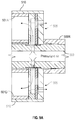
- FIG. 9A illustrates a close-up view of the internal air flow paths through the air distribution plate assembly 505 of the exemplary bidirectional cluster hammer reamer (“BCHR”) of FIG. 5 when it is in a “pull” state such as depicted in FIG. 7 .
- BCHR 500 bidirectional cluster hammer reamer
- FIG. 9A illustrates a close-up view of the internal air flow paths through the air distribution plate assembly 505 of the exemplary bidirectional cluster hammer reamer (“BCHR”) of FIG. 5 when it is in a “pull” state such as depicted in FIG. 7 .
- BCHR 500 bidirectional cluster hammer reamer
- FIG. 9A illustrates a close-up view of the internal air flow paths through the air distribution plate assembly 505 of the exemplary bidirectional cluster hammer reamer (“BCHR”) of FIG. 5 when it is in a “pull” state such as depicted in FIG. 7 .
- the pressurized air (or other pressurized fluid) is delivered to the BCHR 500 via either or both of the forward string and the rear string.
- the pressurized air flows through the central drive rod 503 and enters ports defined by the air distribution plates 505 .
- a minority volume or portion of the pressurized air stream is allowed to exhaust to the exterior of the BCHR 500 (see air flow arrows in illustration) to provide a constant agitation of accreting debris when the BCHR 500 is in the forward advancing cutting mode. Even so, it is envisioned that other embodiments of a BCHR according to the scope of the solution may not provide for exhaust of a minority volume of the pressurized air stream when the BCHR is in the forward advancing cutting mode.
- FIG. 9B illustrates a close-up view of the internal air flow path through the air distribution plate assembly of the exemplary bidirectional cluster hammer reamer (“BCHR”) of FIG. 5 when it is in a “push” state such as depicted in FIG. 8 .
- BCHR 500 bidirectional cluster hammer reamer
- FIG. 9B illustrates a close-up view of the internal air flow path through the air distribution plate assembly of the exemplary bidirectional cluster hammer reamer (“BCHR”) of FIG. 5 when it is in a “push” state such as depicted in FIG. 8 .
- a feed force generated by a “pull” of the rear drill string as opposed to a feed force generated by a “push” of the forward drill string, would also operate to unseat the rear string connector 509 R and direct the internal pressurized air to exhaust at the rear of the BCHR 500 .
- the central drive rod 503 is translated to a rearward most position within the BCHR 500 , thereby causing the rear string connector 509 R to unseat from the back plate of the BCHR 500 .
- the pressurized air flows through the central drive rod 503 and enters ports defined by the air distribution plates 505 .
- the air distribution plates 505 cooperate with cutouts on the exterior of the central drive rod 503 to divert a minority volume or portion of the pressurized air flow to the hammers 501 while simultaneously diverting a majority portion of the pressurized air flow to the exterior of the BCHR 500 (see air flow arrows in illustration). As can be seen in the FIG.
- cutout ports on the exterior of the central drive rod 503 coincide with a gap generated by the unseating of the rear string connector 509 R when the central drive rod 503 is translated to the rearward most position.
- the majority portion of the pressurized air stream that is exhausted to the exterior of the BCHR 500 may work to clear accreted debris.
- the minority portion of the pressurized air stream that is simultaneously supplied to the hammers 501 may provide enough of a motive force to continue the percussive cycle(s) and cause the bits 600 to continue hammering. Even so, it is envisioned that other embodiments of a BCHR according to the scope of the solution may not provide for direction of a minority volume of the pressurized air stream to continue driving the hammers when the BCHR is in the reverse mode.
- the reverse feed force may be replaced with a forward feed force that causes the rear string connector 509 R to reseat and shutoff any exhaust flow of the pressurized air stream to the rear of the BCHR 500 .
- the percussive cycle(s) of the hammers 501 may be maximized and the BCHR 500 urged forward through the pilot bore to continue expansion and conditioning of the bore, as described above.
- each of the verbs “comprise” “include” and “have”, and conjugates thereof, are used to indicate that the object or objects of the verb are not necessarily a complete listing of members, components, elements, or parts of the subject or subjects of the verb.
Abstract
Description
Claims (9)
Priority Applications (1)
| Application Number | Priority Date | Filing Date | Title |
|---|---|---|---|
| US15/939,982 US10626679B2 (en) | 2018-03-29 | 2018-03-29 | Bidirectional cluster hammer reamer |
Applications Claiming Priority (1)
| Application Number | Priority Date | Filing Date | Title |
|---|---|---|---|
| US15/939,982 US10626679B2 (en) | 2018-03-29 | 2018-03-29 | Bidirectional cluster hammer reamer |
Publications (2)
| Publication Number | Publication Date |
|---|---|
| US20190301246A1 US20190301246A1 (en) | 2019-10-03 |
| US10626679B2 true US10626679B2 (en) | 2020-04-21 |
Family
ID=68054843
Family Applications (1)
| Application Number | Title | Priority Date | Filing Date |
|---|---|---|---|
| US15/939,982 Active 2038-04-26 US10626679B2 (en) | 2018-03-29 | 2018-03-29 | Bidirectional cluster hammer reamer |
Country Status (1)
| Country | Link |
|---|---|
| US (1) | US10626679B2 (en) |
Citations (4)
| Publication number | Priority date | Publication date | Assignee | Title |
|---|---|---|---|---|
| US20010006120A1 (en) * | 1999-12-03 | 2001-07-05 | Osamu Miyamoto | Multiple air hammer apparatus and excavating direction correcting method therefor |
| US20090014392A1 (en) * | 2007-07-10 | 2009-01-15 | M-I Llc | Systems and methods for separating hydrocarbons from water |
| US7735584B2 (en) * | 2005-09-20 | 2010-06-15 | Minroc Technical Promotions Limited | Percussion hammer for enlarging drilled holes |
| US9376869B1 (en) * | 2011-08-12 | 2016-06-28 | Directed Technologies Drilling, Inc. | System and method for installing casing in a blind horizontal well |
-
2018
- 2018-03-29 US US15/939,982 patent/US10626679B2/en active Active
Patent Citations (4)
| Publication number | Priority date | Publication date | Assignee | Title |
|---|---|---|---|---|
| US20010006120A1 (en) * | 1999-12-03 | 2001-07-05 | Osamu Miyamoto | Multiple air hammer apparatus and excavating direction correcting method therefor |
| US7735584B2 (en) * | 2005-09-20 | 2010-06-15 | Minroc Technical Promotions Limited | Percussion hammer for enlarging drilled holes |
| US20090014392A1 (en) * | 2007-07-10 | 2009-01-15 | M-I Llc | Systems and methods for separating hydrocarbons from water |
| US9376869B1 (en) * | 2011-08-12 | 2016-06-28 | Directed Technologies Drilling, Inc. | System and method for installing casing in a blind horizontal well |
Also Published As
| Publication number | Publication date |
|---|---|
| US20190301246A1 (en) | 2019-10-03 |
Similar Documents
| Publication | Publication Date | Title |
|---|---|---|
| EP1926881B1 (en) | A percussion hammer for enlarging drilled holes | |
| US6588516B2 (en) | Method and apparatus for directional boring under mixed conditions | |
| US5803187A (en) | Rotary-percussion drill apparatus and method | |
| US7814991B2 (en) | Process and apparatus for subterranean drilling | |
| US5791419A (en) | Drilling apparatus for replacing underground pipes | |
| US10385621B2 (en) | Drill bit for pulling material through pilot-channel | |
| US6397956B1 (en) | Directional drilling tool | |
| SE524375C2 (en) | Method for operating a hammer in a horizontal directional drill | |
| US10508498B2 (en) | Hammer reamer for expanding a pilot bore | |
| US10626679B2 (en) | Bidirectional cluster hammer reamer | |
| US10655392B2 (en) | Horizontal directional drilling system | |
| US6516902B1 (en) | Directional drilling system | |
| US20140367175A1 (en) | Drill bit assembly for a directional percussion boring system | |
| US20150075870A1 (en) | System and method for horizontal directional drilling and product pulling through a pilot bore | |
| US9290993B2 (en) | Method and system for installation of in-ground conduit | |
| WO2023198609A1 (en) | Drill bit assembly for reverse circulation hammer | |
| IES84417Y1 (en) | A percussion hammer for enlarging drilled holes | |
| IE20050621U1 (en) | A percussion hammer for enlarging drilled holes |
Legal Events
| Date | Code | Title | Description |
|---|---|---|---|
| AS | Assignment |
Owner name: HARD ROCK HORIZONTAL DIRECTIONAL DRILLING PRODUCTS Free format text: ASSIGNMENT OF ASSIGNORS INTEREST;ASSIGNORS:COOPER, CARY;PARR, TRAVIS;REEL/FRAME:045387/0889 Effective date: 20180328 Owner name: HARD ROCK HORIZONTAL DIRECTIONAL DRILLING PRODUCTS, INC., GEORGIA Free format text: ASSIGNMENT OF ASSIGNORS INTEREST;ASSIGNORS:COOPER, CARY;PARR, TRAVIS;REEL/FRAME:045387/0889 Effective date: 20180328 |
|
| FEPP | Fee payment procedure |
Free format text: ENTITY STATUS SET TO UNDISCOUNTED (ORIGINAL EVENT CODE: BIG.); ENTITY STATUS OF PATENT OWNER: SMALL ENTITY |
|
| FEPP | Fee payment procedure |
Free format text: ENTITY STATUS SET TO SMALL (ORIGINAL EVENT CODE: SMAL); ENTITY STATUS OF PATENT OWNER: SMALL ENTITY |
|
| STPP | Information on status: patent application and granting procedure in general |
Free format text: RESPONSE TO NON-FINAL OFFICE ACTION ENTERED AND FORWARDED TO EXAMINER |
|
| STPP | Information on status: patent application and granting procedure in general |
Free format text: FINAL REJECTION MAILED |
|
| STPP | Information on status: patent application and granting procedure in general |
Free format text: RESPONSE AFTER FINAL ACTION FORWARDED TO EXAMINER |
|
| STCF | Information on status: patent grant |
Free format text: PATENTED CASE |
|
| MAFP | Maintenance fee payment |
Free format text: PAYMENT OF MAINTENANCE FEE, 4TH YR, SMALL ENTITY (ORIGINAL EVENT CODE: M2551); ENTITY STATUS OF PATENT OWNER: SMALL ENTITY Year of fee payment: 4 |