US6279532B1 - Fuel pressure control apparatus for cylinder injection engine - Google Patents
Fuel pressure control apparatus for cylinder injection engine Download PDFInfo
- Publication number
- US6279532B1 US6279532B1 US09/114,287 US11428798A US6279532B1 US 6279532 B1 US6279532 B1 US 6279532B1 US 11428798 A US11428798 A US 11428798A US 6279532 B1 US6279532 B1 US 6279532B1
- Authority
- US
- United States
- Prior art keywords
- fuel
- fuel pressure
- control
- pipe
- feed
- Prior art date
- Legal status (The legal status is an assumption and is not a legal conclusion. Google has not performed a legal analysis and makes no representation as to the accuracy of the status listed.)
- Expired - Lifetime
Links
Images


Classifications
-
- F—MECHANICAL ENGINEERING; LIGHTING; HEATING; WEAPONS; BLASTING
- F02—COMBUSTION ENGINES; HOT-GAS OR COMBUSTION-PRODUCT ENGINE PLANTS
- F02D—CONTROLLING COMBUSTION ENGINES
- F02D41/00—Electrical control of supply of combustible mixture or its constituents
- F02D41/30—Controlling fuel injection
- F02D41/38—Controlling fuel injection of the high pressure type
- F02D41/3809—Common rail control systems
- F02D41/3836—Controlling the fuel pressure
- F02D41/3863—Controlling the fuel pressure by controlling the flow out of the common rail, e.g. using pressure relief valves
-
- F—MECHANICAL ENGINEERING; LIGHTING; HEATING; WEAPONS; BLASTING
- F02—COMBUSTION ENGINES; HOT-GAS OR COMBUSTION-PRODUCT ENGINE PLANTS
- F02M—SUPPLYING COMBUSTION ENGINES IN GENERAL WITH COMBUSTIBLE MIXTURES OR CONSTITUENTS THEREOF
- F02M69/00—Low-pressure fuel-injection apparatus ; Apparatus with both continuous and intermittent injection; Apparatus injecting different types of fuel
-
- F—MECHANICAL ENGINEERING; LIGHTING; HEATING; WEAPONS; BLASTING
- F02—COMBUSTION ENGINES; HOT-GAS OR COMBUSTION-PRODUCT ENGINE PLANTS
- F02D—CONTROLLING COMBUSTION ENGINES
- F02D41/00—Electrical control of supply of combustible mixture or its constituents
- F02D41/02—Circuit arrangements for generating control signals
- F02D41/04—Introducing corrections for particular operating conditions
- F02D41/06—Introducing corrections for particular operating conditions for engine starting or warming up
- F02D41/061—Introducing corrections for particular operating conditions for engine starting or warming up the corrections being time dependent
-
- F—MECHANICAL ENGINEERING; LIGHTING; HEATING; WEAPONS; BLASTING
- F02—COMBUSTION ENGINES; HOT-GAS OR COMBUSTION-PRODUCT ENGINE PLANTS
- F02D—CONTROLLING COMBUSTION ENGINES
- F02D41/00—Electrical control of supply of combustible mixture or its constituents
- F02D41/30—Controlling fuel injection
- F02D41/38—Controlling fuel injection of the high pressure type
-
- F—MECHANICAL ENGINEERING; LIGHTING; HEATING; WEAPONS; BLASTING
- F02—COMBUSTION ENGINES; HOT-GAS OR COMBUSTION-PRODUCT ENGINE PLANTS
- F02B—INTERNAL-COMBUSTION PISTON ENGINES; COMBUSTION ENGINES IN GENERAL
- F02B2275/00—Other engines, components or details, not provided for in other groups of this subclass
- F02B2275/14—Direct injection into combustion chamber
-
- F—MECHANICAL ENGINEERING; LIGHTING; HEATING; WEAPONS; BLASTING
- F02—COMBUSTION ENGINES; HOT-GAS OR COMBUSTION-PRODUCT ENGINE PLANTS
- F02D—CONTROLLING COMBUSTION ENGINES
- F02D41/00—Electrical control of supply of combustible mixture or its constituents
- F02D41/02—Circuit arrangements for generating control signals
- F02D41/14—Introducing closed-loop corrections
- F02D41/1401—Introducing closed-loop corrections characterised by the control or regulation method
- F02D2041/141—Introducing closed-loop corrections characterised by the control or regulation method using a feed-forward control element
-
- F—MECHANICAL ENGINEERING; LIGHTING; HEATING; WEAPONS; BLASTING
- F02—COMBUSTION ENGINES; HOT-GAS OR COMBUSTION-PRODUCT ENGINE PLANTS
- F02D—CONTROLLING COMBUSTION ENGINES
- F02D41/00—Electrical control of supply of combustible mixture or its constituents
- F02D41/02—Circuit arrangements for generating control signals
- F02D41/04—Introducing corrections for particular operating conditions
- F02D41/042—Introducing corrections for particular operating conditions for stopping the engine
-
- Y—GENERAL TAGGING OF NEW TECHNOLOGICAL DEVELOPMENTS; GENERAL TAGGING OF CROSS-SECTIONAL TECHNOLOGIES SPANNING OVER SEVERAL SECTIONS OF THE IPC; TECHNICAL SUBJECTS COVERED BY FORMER USPC CROSS-REFERENCE ART COLLECTIONS [XRACs] AND DIGESTS
- Y02—TECHNOLOGIES OR APPLICATIONS FOR MITIGATION OR ADAPTATION AGAINST CLIMATE CHANGE
- Y02T—CLIMATE CHANGE MITIGATION TECHNOLOGIES RELATED TO TRANSPORTATION
- Y02T10/00—Road transport of goods or passengers
- Y02T10/10—Internal combustion engine [ICE] based vehicles
- Y02T10/12—Improving ICE efficiencies
Definitions
- the present invention generally relates to fuel pressure control apparatus for cylinder injection engine, and particularly to a fuel pressure control apparatus for cylinder injection engine which is suited to control the fuel pressure in the range from the start of engine to the stationary state, the fuel pressure at the time of the transient from the stationary state, and the fuel pressure at the time when fuel is cut.
- the conventional fuel pressure control apparatus for cylinder injection engine has a high-pressure fuel pump to be driven by engine, and a low-pressure fuel pump provided on the upper stream side of the high-pressure fuel pump in order that the high-pressure fuel can be directly injected into combustion chambers through high-pressure fuel injection valves that are provided in the respective combustion chambers of the engine.
- the fuel pressure in the pipes at the high-pressure fuel injection valves is controlled by fuel pressure adjusting means which makes feed back control so that the actual fuel pressure measured by fuel pressure detecting means can be coincident with a target value that is optimum to the engine speed.
- An example of the fuel pressure control apparatus with the above drawback removed is proposed as for example disclosed in JP-A-5-149168.
- different fuel pressure control systems are respectively used at the start when the discharge pressure of the high-pressure fuel pump driven by engine is unstable and at the normal driving condition.
- an actual fuel pressure signal is supplied to a fuel pressure regulator of the high-pressure fuel system, and a control system makes feed-back control in order to cause the actual fuel pressure value to coincide with a target fuel pressure value.
- This control system includes start discriminating means for deciding whether the engine starts, and fuel pressure control extent calculating means which supplies a fuel pressure signal for that control extent according to the target fuel pressure value when the engine starts.
- the fuel pressure is controlled in a feed-back manner, while at the start when the discharge pressure of the pump is unstable the fuel pressure is controlled in a feed-forward manner by a fuel pressure signal according to only the target fuel pressure value as a fixed amount of control, thereby stabilizing the fuel pressure control.
- this conventional fuel pressure control apparatus is constructed to stop the feed back control when the fuel pressure in the pipes at around the fuel injection valves is most greatly changed, or at the start time.
- the voltage of the battery as a driving power supply is reduced, sometimes making even the operation for driving the feed-forward control unstable.
- the fuel pressure in the pipes at around the fuel injection valves is controlled in a feed-forward manner by the fuel pressure signal according to only the target fuel pressure value as a fixed amount of control, it is not possible to assure the stabilization of the fuel pressure control at the time of start.
- the above proposed technique does not consider these points.
- the fuel pressure feed-back control consider the change of the target fuel pressure of engine due to the abrupt change of driving conditions at the transient or the like.
- the target value is abruptly changed, or when the fuel pressure is, for example, instantaneously increased and then decreased, a proper amount of control for feed back is not given, so that the actual fuel pressure sometimes overshoots or undershoots.
- a fuel pressure control apparatus of cylinder injection engine having a fuel pump, fuel injection valves, a pipe system connecting the fuel pump and the fuel injection valves, and a fuel pressure regulator provided in the pipe system and which discharges fuel from the pipe system to thereby adjust the fuel pressure, the fuel pressure regulator being controlled to stop discharge of fuel from the pipe system for a predetermine time from the start of engine.
- a more specific example of the above fuel pressure control apparatus has fundamental duty calculating means, target fuel pressure calculating means, actual fuel pressure calculating means, fuel pressure correction calculating means, fundamental duty correcting means, and output duty calculating means, wherein the output duty calculating means controls the output duty value to the fuel pressure regulator to be zero for a predetermined time from when the start of engine is detected.
- the above construction of the invention controls the discharge of fuel from the pipe system to stop without supplying an amount of control to the fuel pressure regulator when the engine starts, the fuel fed into the fuel pipes from the fuel pump is not discharged so that the pressure within the pipes can be fast increased, with the result that fuel can be injected stably at the time of engine start. That is, at the time of engine start the fuel pipe system discharges only the necessary fuel to be injected from the fuel injection valves, and is closed at the other time. Since the closed space can be formed only by closing the pressure control opening of the fuel pressure regulator without electric energy, the effect of power supply voltage or the like can be avoided, and the pressure in the pipes can be increased fastest.
- the fundamental duty calculating means computes a fundamental duty value on the basis of a load signal to the engine and revolution rate of engine
- the fuel pressure correction calculating means calculates a fuel pressure control deviation and a duty correction value on the basis of the target fuel pressure and actual fuel pressure, and decides whether feed-back control is permitted.
- the fundamental duty value is corrected according to the duty correction value and supplied to the output duty calculating means.
- the output duty calculating means at the time of start, selectively makes the closing control of the fuel pressure regulator, feed-forward control or feed-back control on the basis of the battery voltage or a signal for fuel cut or the like.
- the fuel pressure regulator is controlled to keep the fuel discharge opening in a certain state for a constant time after a certain time has elapsed from the start of engine, and then controlled in a feed-back manner so that the actual fuel pressure reaches the target fuel pressure.
- the output duty value to the fuel pressure regulator is controlled to be constant for a constant time, and then the fuel pressure correction value calculating means makes feed-back control so that the actual fuel pressure can reach the target value.
- the feed-back control is stopped, and the fuel pressure is controlled on the basis of the amount of feed-back at that time and the reference amount of control that depends on that driving conditions, and then placed under the feed-back control after the target fuel pressure and actual fuel pressure continue to be maintained in certain ranges for a predetermined time under the reference amount of control.
- the feed-back control when the target fuel pressure is suddenly changed, for example instantaneously increased and then decreased, the feed-back control is stopped, and the fuel pressure is controlled in a feed-forward manner on the basis of not only the reference duty value (reference amount of control) but also the amount of feed back indicated when the feed-back control is stopped in order to absorb the scattering, thereby improving the ability of control at the transient time.
- the feed-back control resumes the fuel in the pipes is stable, and thus the actual fuel pressure can be well converged.
- the fuel pressure regulator is controlled to cause the pipe system to discharge the maximum fuel under the condition that the fuel injection valves are controlled to inject the minimum amount of fuel including no injection.
- the output calculating means controls the output duty to the fuel regulator to be 100% under the condition that the fuel injection valves are controlled to inject the minimum amount of fuel including no injection.
- a certain amount of control is added to the amount of control calculated on the basis of feed-back control.
- the area of the opening of the fuel pressure regulator can be maximized, thus making it possible to positively remove the foreign matter such as abrasion powder or dust collected within the pipe system and fuel pressure regulator.
- the pipe system When the area of the opening is the maximum under the driving state, the pipe system generally increases discharge gas to reduce the fuel pressure to a predetermined value or below, but under the fuel cut state, the reduction of the pressure within the pipe system has no effect. In addition, since at the time of recovery it is necessary to swiftly return to a preset pressure, a certain amount of control offset is given, and fuel control is made to fast stabilize the fuel pressure.
- FIG. 1 is a general view of a cylinder injection engine having a fuel pressure control apparatus of one embodiment of the invention.
- FIG. 2 is a block diagram of an example of the control unit shown in FIG. 1 .
- FIG. 3 is a longitudinal cross-sectional diagram of one example of the construction of the variable fuel pressure regulator shown in FIG. 1 .
- FIGS. 4 and 5 are graphs showing characteristics of the variable fuel pressure regulator.
- FIG. 6 is a block diagram of the control unit of FIG. 1 showing the concept of the fuel pressure control operation.
- FIG. 7 is a target fuel pressure map diagram of the target fuel pressure control means shown in FIG. 6 .
- FIG. 8 is a fundamental duty map diagram of the fundamental duty calculating means shown in FIG. 6 .
- FIG. 9 is a map diagram of another example of those shown in FIGS. 7 and 8.
- FIG. 10 is a graph showing a characteristic of the fuel pump shown in FIG. 1 .
- FIG. 11 is a diagram showing one example of the control characteristics of the variable fuel regulator shown in FIG. 3 .
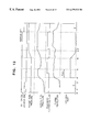
- FIG. 12 is a timing chart to which reference is made in explaining the operation of the invention.
- FIGS. 13 to 15 are flowcharts to which reference is made in explaining an example of the operation of the invention at the start time of engine.
- FIGS. 16 and 17 are flowcharts to which reference is made in explaining the operation in the case where the target value is greatly changed in the fuel pressure control apparatus of the invention.
- FIG. 18 is a flowchart showing one example of the operation of the invention in the case where the engine is stopped.
- FIG. 19 is a flowchart to which reference is made in explaining one example of the operation for the compensation of battery voltage change.
- FIG. 20 is a timing chart to which reference is made in explaining the operation at the time of fuel cut.
- FIGS. 21 and 22 are flowcharts showing one example of the operation at the time of fuel cut.
- FIG. 23 is a flowchart showing an example different from that shown in FIG. 22 .
- FIG. 1 shows the whole construction of an engine system including this embodiment of the fuel pressure control apparatus for cylinder injection engine.
- an engine 507 that is composed by each cylinder including a piston 507 a , a cylinder 507 b and a combustion chamber 507 c formed by the piston 507 a and cylinder 507 b , and by an inlet pipe 501 and exhaust pipe 519 provided above the combustion chamber 507 c to be connected to the chamber.
- the air to be sucked into the engine 507 is introduced from an inlet 502 a of an air cleaner 502 , and fed through an air flow sensor 503 and through a throttle body 505 having a throttle valve 505 a housed for controlling the sucked air flow to a collector 506 .
- the air in the collector 506 is distributed into the inlet pipes 501 which are respectively connected to the cylinders 507 b of the engine 507 , and fed to each cylinder 507 b .
- the throttle valve 505 a can be opened and closed by a motor 522 .
- the exhaust gas after combustion from the combustion chamber 507 c is discharged through the exhaust pipe 519 and a catalyst 520 .
- fuel such as gasoline from a fuel tank 514 is subjected to a first pressure by a fuel pump 510 and supplied to a pipe 541 .
- the fuel in the pipe is subjected to a second pressure by a fuel pump 511 , and fed to a pipe 542 .
- This pipe 542 is composed by two up and down pipes between which an injector 509 is interposed to form a fuel pipe system.
- the fuel subjected to the first pressure by the fuel pump 510 and fed to the pipe 541 is adjusted to be kept at a constant pressure (for example, 3 kg/cm 2 ) by a fuel pressure regulator 512 , and it is secondly pressed by the fuel pump 511 to be raised to a higher pressure, and fed to the pipe 542 .
- the fuel fed to the pipe 542 is adjusted to be at a constant pressure (for example, 70 kg/cm 2 by a fuel pressure regulator 513 , and injected into the cylinder 507 b from the injector 509 that is provided in each cylinder 507 b of the engine 507 .
- the fuel pressure within the pipe 542 between the fuel pump 511 and the injector 509 is fundamentally controlled by the fuel pressure regulator 513 . If an amount of control is not supplied to this fuel pressure regulator 513 , or if the control system is disabled, a mechanical regulator 540 is instead operated to adjust.
- the fuel injected from the injector 509 is ignited by an ignition coil 508 in response to an ignition signal boosted to a high voltage by an ignition coil 522 .
- the air flow sensor 503 generates a signal indicating a sucked air flow, and supplies it to a control unit 515 .
- the throttle body 505 has a throttle sensor 504 mounted to detect the degree of opening of the throttle valve 505 a .
- the output signal from the sensor is also supplied to the control unit 515 .
- a crank angle sensor 516 mounted on a cam shaft (not shown) of the engine 507 generates a reference angle signal REF indicating the rotational position of the crankshaft and an angle signal POS for detecting a rotation signal (revolution rate) signal, and also supplies them to the control unit 515 .
- an A/F sensor 518 On the upstream side of the catalyst 520 of the exhaust pipe 519 , there is disposed an A/F sensor 518 .
- An accelerator opening sensor 521 is also provided in the engine 507 . The signals from these sensors are also supplied to the control unit 515 .
- the main portion of the control unit 515 is formed by an MPU, a ROM, a RAM, an I/O LSI including an A/D converter, and so on.
- the control unit receives the signals from the above-mentioned sensors which detect the driving conditions of the engine, executes predetermined computing processes, generates various different control signals as a result of the calculation, and supplies certain control signals to the injector 509 and ignition coil 522 , thus making fuel supply control and ignition timing control.
- the fuel pressure sensor 523 detects the pressure within the pipe 542 and supplies the control signal to the fuel pressure regulator, or variable pressure/regulator (variable P/Reg) 513 .
- This control signal controls the time in which the valve of the variable P/Reg 513 is opened, or the duty value indicating the ratio of the valve-open time to the valve-closed time.
- FIG. 3 is a longitudinal cross-sectional view of the variable P/Reg 513 .
- the fuel within the pipe 542 enters into the variable P/Reg 513 from the IN side shown in FIG. 3, and discharged into the pipe 541 a on the OUT side shown in FIG. 3, or fed back to the pipe 541 .
- variable P/Reg 513 When no control signal is supplied to the variable P/Reg 513 from the control unit 515 , a ball valve 701 of the variable P/Reg 513 is pressed against a valve seat 700 by a spring 702 , and the fuel from the IN side of the pipe 542 is not discharged to the pipe 541 a side. Since the fuel is not discharged from the pipe 542 , the pressure within the pipe 542 is determined by the amount of fuel discharged from the fuel pump 511 and the amount of fuel injected by the injector 509 . However, the maximum pressure within the pipe 542 is limited by the mechanical regulator 540 .
- the amount that the ball valve 701 is controlled by the variable P/Reg 513 is adjusted by the duty value supplied as the duty signal to an electromagnetic coil 703 from the control unit 515 .
- the sucking force of a plunger 704 which supports the ball valve 701 is controlled by the average current of the electromagnetic coil 703 so as to control the amount of fuel escaped from the valve seat 700 .
- the actual pressure within the pipe 542 can be controlled to reach the target fuel pressure.
- FIG. 4 is a graph showing a fundamental characteristic of the variable P/Reg 513 , in which the ordinate indicates the fuel pressure within the pipe 542 . If the duty value is 0%, or if the amount of control is zero, the pressure within the pipe 542 becomes high since there is no escape fuel. However, the upper limit of the pressure is suppressed by the mechanical regulator 540 . If the duty value increases, the escape fuel from the pipe 542 increases, thus reducing the pressure as shown in the graph.
- FIG. 5 shows a typical example of the voltage characteristic of the variable P/Reg 513 . From FIG. 5, it will be seen that if the driving voltage, or battery voltage is changed, the driving current is changed even under constant duty so that the fuel pressure varies. Thus, it will be understood that the variation of the battery voltage can be compensated by changing the duty value.
- FIG. 6 is a block diagram showing the control operation to be executed by the control unit 515 .
- Fundamental duty calculating means 101 calculates an engine revolution rate Ne from the detected signal which it receives from the crank angle sensor 516 , and an engine load T from the detected signal which it receives from the accelerator opening sensor 521 , and determines the fundamental duty value for controlling the variable P/Reg 513 on the basis of those calculated values.
- Target fuel pressure calculating means 102 also determines the target fuel pressure from the engine revolution rate Ne and the engine load T.
- Actual fuel pressure calculating means 103 converts the received detected value from fuel pressure sensor 523 into an actual fuel pressure.
- Fuel pressure correction calculating means 104 compares the target fuel pressure from the target fuel pressure calculating means 102 and the actual fuel pressure from the actual fuel pressure calculating mean 103 to produce a deviation between both, and calculates an amount of fuel pressure correction on the basis of that deviation.
- the fuel pressure correction calculating means 104 also confirms if the target fuel pressure value is in a predetermined range and decides if the feed-back control can be permitted.
- Limiter process means 105 sets the upper and lower limits of the amount of fuel correction calculated by the fuel pressure correction calculating means 104 .
- Fundamental duty correction means 107 corrects the fundamental duty value from the fundamental duty calculating means 101 on the basis of the amount of fuel pressure correction from the limiter means 105 , and produces a corrected duty value.
- Output duty calculating means 106 decides if the driving state of engine is starting or at the time of F/C (fuel cut).
- the output duty calculating means 106 corrects the amount of control (duty value) to be applied to the variable P/Reg 513 in accordance with the driving voltage, and produces the corrected amount of control, since the duty-fuel pressure characteristic is changed with the driving voltage fed to the variable P/Reg 513 as shown in FIG. 5 .
- FIG. 7 shows a target fuel pressure map for reading a target fuel pressure on the basis of the engine revolution rate Ne and the load torque T.
- the load torque is computed by the well-known method on the basis of the detected signals from the accelerator opening sensor 521 , air flow sensor 503 , throttle sensor 504 and air-fuel ratio sensor 518 .
- the accelerator opening sensor 521 of these sensors is typically shown in FIG. 6 .
- the target fuel pressure calculating means 102 reads out the target fuel pressure value with reference to FIG. 7 on the basis of the engine revolution rate Ne and load torque T.
- FIG. 8 is a fundamental duty map for reading out the fundamental duty value by the fundamental duty calculating means 102 on the basis of the engine revolution rate Ne and load torque T as in FIG. 7 .
- the load axis is represented by torque in FIGS. 7 and 8
- the load axis in the target fuel pressure map and fundamental duty map may be shown as in FIG. 9 by the amount of fuel, q which has a close mutual relation with the degree of accelerator opening and which is injected from the injector 509 .
- the fuel pump 511 is driven directly by the engine.
- the amount of fuel discharged from the pump 511 is proportional to the revolution rate of engine, Ne, or the revolution rate of the pump.
- the amount of fuel discharged from the pump is represented by Q when the revolution rate of the engine is N3.
- FIG. 11 is a graph showing a fuel pressure vs. fuel return amount (escaped amount of fuel) characteristic with a parameter of duty value in the variable P/Reg 513 .
- the amount of fuel discharged from the pump is Q.
- the torque is T2, or the amount of injected fuel is q2.
- the fuel return amount Qret in the variable P/Reg 513 is expressed by
- the fundamental duty value at the operating point N3, T2 is 60% with reference to FIG. 8
- the fuel pressure Pset in the pipe 542 at the above operating point can be determined from the intersection point between the return amount Qret line and the fundamental duty 60% line with reference to FIG. 11 .
- the fundamental duty value can be determined on the basis of the revolution rate of engine and the amount of injected fuel.
- control unit 515 The operation of the control unit 515 will be described with respect to time from the start of engine.
- variable P/Reg 513 is the minimum, or zero in its opening area, and thus the amount of fuel to be returned to the pipe 541 from the pipe 542 through the pipe 541 a is zero.
- step 5001 decision is made of whether the starter switch is turned from on-state to off-state. Since the starter switch is now in the off state, the decision is No, and thus the program goes to step 5002 .
- step 5002 decision is made of whether the engine speed Ne is larger than a revolution rate Nset. Since the engine is now not started yet, the decision is No, and thus the program goes to step 5003 , where the start flag is set. Then, the program ends this flow.
- step 4001 decision is made of whether the start flag set at step 5003 in FIG. 3 is set or not. Since the start flag is now set, the decision is Yes, and thus the program goes to step 4002 , where the output from the output duty calculating means 106 is set at 0%. Then, the program ends this flow.
- step 5001 in FIG. 13 the decision is Yes, and the start flag is set. Then, when the starter switch is turned off at time t2, at this step the decision is No, and the program goes to step 5002 .
- the decision is No when the engine speed Ne is not larger than the predetermine value Nset, and thus the start flag is kept set. Therefore, as in the operation flow shown in FIG. 14, the output duty value of the variable P/Reg 513 is maintained to be 0%.
- step 5002 If at step 5002 the engine speed Ne is decided to have reached the predetermined value or above (time t3), or if the engine is decided to have started, or be Yes, the program goes to step 5004 , where the start flag is cleared. Then, the program ends this flow. Thereafter, as long as the revolution rate Ne is maintained to be the predetermined value Nset or above, the start flag is continuously cleared at step 5004 . After the start flag is cleared, at step 4001 in FIG. 15 the decision is No, and the program ends this flow. Thus, at time t3, the control for the output duty value of 0% ends.
- FIGS. 13 and 14 are useful for explaining the operation of the output duty calculating means 106 in FIG. 6 .
- the output duty calculating means 106 controls the duty to be 0% so that the fuel discharged from the pump 511 is not again returned to the pipe 541 side by the variable P/Reg 513 , and the pressure within the pipe 542 to fast increase, thus swiftly bringing about the state in which normal fuel injection can be made.
- the engine ends the start condition at time t3, but the actual fuel pressure is not stabilized yet.
- the feed-back control is immediately performed from this state, the engine operation may become unstable.
- the feed-back control is not executed until it is confirmed that the actual fuel pressure within the pipe 542 is kept stable over a predetermined time.
- FIG. 15 shows the operation flow that is executed in parallel with the above operation.
- a fixed duty flag is raised for a certain time Tmax after the starting state end time t3, and the variable P/Reg 513 is controlled by the fixed duty.
- the fixed duty may be replaced by the fundamental duty.
- the fuel pressure correction calculating means 104 does not produce any amount of correction, and the fundamental duty itself is supplied to the output duty calculating means 106 so that the feed-forward control is performed.
- the operation flow of FIG. 15 is started every certain time.
- FIG. 16 shows the operation flow which is started every certain time to detect that the target fuel pressure has been greatly changed to exceed a predetermined value.
- a target fuel pressure value is searched for from the target fuel pressure calculating means 102 .
- the searched target fuel pressure value is compared with the previous one so that decision is made of whether it is equal to or larger than that. Since the flow is now between time t3 and time t4, the target fuel pressure is not greatly changed. Here, the decision is No, and at step 3005 the feed-back start decision flag is set. Then, the program ends this flow.
- FIG. 17 shows the operation flow which is started every predetermined time to confirm that the actual fuel pressure has been maintained stable for a certain time and execute the feed-back control.
- decision is made of whether the feed-back decision flag that is to be set at step 3005 in FIG. 16 is set or not. Since the feed-back start decision flag is now set, the decision at step 1001 is Yes.
- decision is made of whether the actual fuel pressure is between the upper limit High and the lower limit Low, or whether the actual fuel pressure has been maintained stable within a predetermined range.
- the decision is No
- the feed-back operation is not allowed, and the feed-back allowance flag is cleared. Then, the program ends this flow.
- step 1003 decision is made of whether the actual fuel pressure has been maintained stable for a predetermined time.
- a timer makes continuous counting, and the program goes back to step 1002 .
- the program goes to step 1004 , where the feed-back allowance flag is set, and the feed-back start decision flag is cleared. Then, the program ends this flow.
- the feed-back control is performed under normal conditions, but at the start time the feed-back control is not started when the operation flow in FIG. 15 is before time t4.
- the feed-back start decision flag is set at step 3005 , and when time t4 has passed, the feed-back control is executed.
- the fuel pressure correction calculating means 104 calculates the deviation ⁇ P between the target fuel pressure obtained by the target fuel pressure calculating means 102 and the actual fuel pressure detected by the fuel pressure sensor 523 , and multiplies this deviation by a predetermined value to produce a proportional control amount Pc.
- a predetermined value for example, 5 Kg/m 2
- a fixed value is added to the previous integral control amount to produce an integral control amount Ic.
- the sum of the proportional control amount Pc and the integral control amount Ic is produced as an amount of feed-back control.
- the fundamental duty correction means 107 corrects the fundamental duty value from the fundamental duty calculating means 101 with the amount of feed-back control from the fuel pressure correction calculating means 104 , and supplies the corrected duty value to the output control means 513 .
- the decision at this step is Yes, and the program goes to step 3003 .
- the amount of feed-back at that time, or the output from the fuel pressure correction calculating means 104 at that time is stored in a memory 110 , and the feed-back allowance flag is cleared. Then, the program ends this flow.
- the feed-back allowance flag is cleared, the feed-back control is stopped, and the fuel pressure correction calculating means 104 does not supply the amount of correction to the fundamental duty correcting means 107 .
- the period of this feed-forward control corresponds to the period from time t5 to time t7 in FIG. 12 .
- the feed-forward control is performed on the basis of the duty value that is the sum of the fundamental duty value and the amount of feed-back stored at step 3003 .
- the feed-back start decision flag is set at step 3005 .
- the decision is Yes.
- the feed-back control is again started from time t7 in FIG. 12 .
- FIG. 18 shows the operation flow for maintaining the fuel pressure high when the engine is stopped. This operation is performed by the output duty calculating means 106 .
- step 6001 decision is made of whether the ignition switch is turned off from the on state.
- the output duty 0% flag is set first of all at step 6002 , considering the case where the engine is started immediately after the stop of the engine. Consequently, the output duty calculating means 106 controls to makes the following control duty 0%, and maintain the pressure within the pipe 542 to be left unchanged.
- the decision at step 6001 is No.
- decision is made of whether the engine is stopped. If the decision here is Yes, the program goes to step 6002 , where the output duty 0% flag is set considering the case in which the engine is immediately again started.
- the output duty calculating means 106 makes the following control duty 0%, and maintains the pressure within the pipe 542 left unchanged. If the decision at step 6003 is No, the program goes to step 6004 , where the output duty 0% flag is cleared. Then, the program ends this flow.
- FIG. 19 shows the flow for the compensation. This flow is started every predetermined time to be performed by the output duty calculating means 106 .
- computation is made for the correction of the battery voltage. In this correction computation, since the fundamental duty is defined on the basis of the battery voltage, the output duty value is corrected by the actual battery voltage. In other words, the corrected duty Dout can be expressed by
- Dc is the output duty
- Vbase is the reference battery voltage
- Vb is the actual battery voltage
- the F/C signal indicating fuel cut is generated, thus controlling the control duty value to be 100%, and the opening area of variable P/Reg 513 to be the maximum.
- the fuel pressure within the pipe is not under a particular control, and the injector 508 injects no fuel. Therefore, since the fuel discharge area is the maximum, the abrasion powder discharged from the pump 511 and dust flowing into the pipe 542 can be removed through the variable P/Reg 513 particularly from the valve seat 700 and ball valve. This operation is performed by the output duty calculating means 106 . The operation will be described with reference to FIGS. 20 to 22 .
- the actual fuel pressure is decreased away from the target value after that time point as shown in FIG. 20 .
- the actual fuel pressure cannot be suddenly shifted from the lower value to the target value set in the feed-back control even if the same amount of control as when the F/C signal is generated is applied.
- the fuel pressure gradually approaches to the target value with a time lag. Since it is desired that the actual fuel pressure swiftly follow the target value in the engine control, it is necessary to fast remove the time lag.
- the output duty calculating means 106 controls the lag in the fuel pressure restoration to be the minimum when the original state is recovered from the F/C state. That is, the final control duty value is given an offset to be small, accelerating the fuel pressure restoration.
- FIG. 21 is the operation flow which is started every predetermined time to detect the F/C signal at time ta.
- decision is made of whether the F/C signal is applied or not at step 8001 . If the decision here is Yes, the program goes to step 8002 , where the amount of feed-back, F/B produced from the fuel pressure correction calculating means 104 at that time is stored in the memory 110 , and the duty 100% flag is set. Then, the program ends this flow. If the decision at step 8001 is No, the program goes to step 8003 , where the duty 100% flag is cleared. Then, the program ends this flow.
- the output duty calculating means 106 causes the variable P/Reg 513 to operate at duty 100%, and the abrasion powder and dust to be quickly removed from the pipe 542 and variable P/Reg 513 .
- FIG. 22 shows the operation flow at tb at which the F/C signal falls off.
- decision is made of whether the duty 100% flag to be set at step 8002 in FIG. 21 is once set and then cleared. If the decision here is No, the program ends this flow. If the decision is Yes, the F/C signal falls off at time tb, and thus at step 8011 the duty is set at the recovery time.
- the recovery-time duty is determined by adding the fundamental duty produced from the fundamental duty calculating means 101 at that time, the feed-back amount F/B stored in the memory at step 8002 in FIG. 21, and a predetermined offset for reducing the control duty value. Since the feed-back control on the fuel pressure is performed on the duty value determined in this way, the fuel pressure within the pipe 542 can be quickly restored by applying this offset.
- the offset is empirically determined. In addition, the offset can be released from when the fuel pressure is well recovered.
- FIG. 23 shows the operation flow for making this operation.
- the attenuation flag is set at step 8011 in FIG. 22 .
- the flow of FIG. 23 is started. First at step 8021 , it is checked if the attenuation flag is set at step 8021 . If the decision here is No, this flow ends. If the decision is Yes, the program goes to step 8022 , where a minute amount of offset is subtracted from the current offset, and the remainder, or new offset is set. Then, at step 8023 , decision is made of whether the new offset has become zero or negative. If the decision here is No, this flow ends.
- step 8024 the offset may be compared with a certain small value in place of zero. Since the operation flow of FIG. 23 is repeatedly performed every predetermined time, the offset of the control duty is reduced stepwise as shown in FIG. 20 after time tb.
Landscapes
- Engineering & Computer Science (AREA)
- Chemical & Material Sciences (AREA)
- Combustion & Propulsion (AREA)
- Mechanical Engineering (AREA)
- General Engineering & Computer Science (AREA)
- Electrical Control Of Air Or Fuel Supplied To Internal-Combustion Engine (AREA)
- Fuel-Injection Apparatus (AREA)
Applications Claiming Priority (2)
| Application Number | Priority Date | Filing Date | Title |
|---|---|---|---|
| JP18957697A JP3612175B2 (ja) | 1997-07-15 | 1997-07-15 | 筒内噴射エンジンの燃料圧力制御装置 |
| JP9-189576 | 1997-07-15 |
Publications (1)
| Publication Number | Publication Date |
|---|---|
| US6279532B1 true US6279532B1 (en) | 2001-08-28 |
Family
ID=16243649
Family Applications (1)
| Application Number | Title | Priority Date | Filing Date |
|---|---|---|---|
| US09/114,287 Expired - Lifetime US6279532B1 (en) | 1997-07-15 | 1998-07-13 | Fuel pressure control apparatus for cylinder injection engine |
Country Status (5)
| Country | Link |
|---|---|
| US (1) | US6279532B1 (fr) |
| EP (1) | EP0892168B1 (fr) |
| JP (1) | JP3612175B2 (fr) |
| KR (1) | KR19990013856A (fr) |
| DE (1) | DE69834773T2 (fr) |
Cited By (14)
| Publication number | Priority date | Publication date | Assignee | Title |
|---|---|---|---|---|
| US6701905B1 (en) * | 2003-04-30 | 2004-03-09 | Delphi Technologies, Inc. | Fuel pressure control method for an alternate-fuel engine |
| US6748924B2 (en) * | 2001-09-18 | 2004-06-15 | Hyundai Motor Company | Method and system for controlling fuel injection |
| US20050087174A1 (en) * | 2003-10-24 | 2005-04-28 | Guenter Veit | Method for regulating the pressure in a fuel accumulator of an internal combustion engine |
| US20050274362A1 (en) * | 2004-06-15 | 2005-12-15 | Deraad Scott | System and method to prime an electronic returnless fuel system during an engine start |
| US20080005964A1 (en) * | 2004-12-17 | 2008-01-10 | Texaco Inc. | Apparatus and method for controlling compressor motor speed in a hydrogen generator |
| US20110023833A1 (en) * | 2009-07-31 | 2011-02-03 | Ford Global Technologies, Llc | Fuel system control |
| US20110231080A1 (en) * | 2008-11-24 | 2011-09-22 | Mtu Friedrichshafen Gmbh | Control and regulation method for an internal combustion engine having a common rail system |
| US20120097131A1 (en) * | 2009-07-02 | 2012-04-26 | Mtu Friedrichshafen Gmbh | Method for the closed-loop control of the rail pressure in a common-rail injection system of an internal combustion engine |
| CN102817735A (zh) * | 2012-08-21 | 2012-12-12 | 潍柴动力股份有限公司 | 一种高压共轨系统中轨压前馈控制量的修正方法和装置 |
| US20150144109A1 (en) * | 2012-06-21 | 2015-05-28 | Hitachi Automotive Systems, Ltd. | Control Device for Internal Combustion Engine |
| US20150354490A1 (en) * | 2012-12-20 | 2015-12-10 | Mtu Friedrichshafen Gmbh | Method for operating an internal combustion engine |
| US20160040613A1 (en) * | 2013-03-28 | 2016-02-11 | Yanmar Co., Ltd. | Engine |
| US20160201589A1 (en) * | 2015-01-14 | 2016-07-14 | Toyota Jidosha Kabushiki Kaisha | Control device for internal combustion engine |
| US9624860B2 (en) | 2009-10-30 | 2017-04-18 | Mtu Friedrichshafen Gmbh | Method for the control and regulation of a V-type internal combustion engine |
Families Citing this family (6)
| Publication number | Priority date | Publication date | Assignee | Title |
|---|---|---|---|---|
| JP2001159359A (ja) * | 1999-12-02 | 2001-06-12 | Mitsubishi Electric Corp | 筒内噴射エンジンの燃圧制御装置 |
| JP3511492B2 (ja) * | 1999-12-14 | 2004-03-29 | 三菱電機株式会社 | 筒内噴射エンジンの燃料噴射制御装置 |
| EP1238190B1 (fr) * | 1999-12-15 | 2004-09-22 | Siemens Aktiengesellschaft | Procede pour ameliorer le demarrage d'un moteur a combustion interne equipe d'un systeme d'injection haute pression |
| DE102005029138B3 (de) | 2005-06-23 | 2006-12-07 | Mtu Friedrichshafen Gmbh | Steuer- und Regelverfahren für eine Brennkraftmaschine mit einem Common-Railsystem |
| KR100840871B1 (ko) * | 2007-06-07 | 2008-06-23 | 콘티넨탈 오토모티브 시스템 주식회사 | 엘피지 직접 분사식 시스템용 가변 압력 조절 장치 및 그 제어 방법 |
| DE102008036299B3 (de) | 2008-08-04 | 2009-12-03 | Mtu Friedrichshafen Gmbh | Verfahren zur Druckregelung |
Citations (20)
| Publication number | Priority date | Publication date | Assignee | Title |
|---|---|---|---|---|
| US4791905A (en) * | 1985-04-02 | 1988-12-20 | Nippondenso Co., Ltd. | Control apparatus for a vehicle engine electric fuel pump |
| US4982331A (en) * | 1988-01-25 | 1991-01-01 | Mitsubishi Denki Kabushiki Kaisha | Fuel injector control apparatus |
| US5074272A (en) | 1986-08-13 | 1991-12-24 | Ashland Oil, Inc. | Process and apparatus for reducing port fuel injector deposits |
| US5121604A (en) | 1988-05-07 | 1992-06-16 | Robert Bosch Gmbh | Control of supercharged internal combustion engines |
| JPH04339143A (ja) | 1991-05-16 | 1992-11-26 | Fuji Heavy Ind Ltd | エンジンの燃料圧力制御方法 |
| JPH05149168A (ja) * | 1991-11-29 | 1993-06-15 | Fuji Heavy Ind Ltd | 筒内直噴式エンジンの燃圧制御装置 |
| US5261378A (en) * | 1989-08-03 | 1993-11-16 | Robert Bosch Gmbh | Device for producing a desired value of a control parameter of an internal combustion engine |
| US5313923A (en) * | 1991-04-24 | 1994-05-24 | Nippondenso Co., Ltd. | Control apparatus for fuel pump |
| US5327872A (en) | 1992-10-15 | 1994-07-12 | Fuji Jukogyo Kabushiki Kaisha | Fuel pressure control method for high pressure direct fuel injection engine |
| US5379741A (en) | 1993-12-27 | 1995-01-10 | Ford Motor Company | Internal combustion engine fuel system with inverse model control of fuel supply pump |
| US5441026A (en) | 1993-11-18 | 1995-08-15 | Fuji Jukogyo Kabushiki Kaisha | Fuel pressure control system for high pressure fuel injection engine |
| US5483940A (en) * | 1992-11-09 | 1996-01-16 | Unisia Jecs Corporation | Apparatus and a method for controlling fuel supply to engine |
| DE4443836A1 (de) | 1994-12-09 | 1996-06-13 | Bosch Gmbh Robert | Einrichtung zur Kraftstoffversorgung für eine Brennkraftmaschine |
| FR2730526A1 (fr) | 1995-02-13 | 1996-08-14 | Marwal Systems | Dispositif d'alimentation en carburant pour vehicule automobile avec regulation de pression |
| JPH094498A (ja) * | 1995-03-28 | 1997-01-07 | Elasis Sistema Ric Fiat Nel Mezzogiorno Soc Consortile Per Azioni | 加圧流体蓄圧器の加圧流体供給調節装置 |
| DE19640826A1 (de) | 1995-10-03 | 1997-04-10 | Nippon Soken | Speicherkraftstoffeinspritzsystem |
| EP0780559A2 (fr) | 1995-12-22 | 1997-06-25 | Robert Bosch Gmbh | Méthode et dispositif pour commander un moteur à combustion interne |
| US5694902A (en) * | 1995-12-12 | 1997-12-09 | Denso Corporation | Fuel supply control with fuel pressure adjustment during fuel cut-off delay period |
| US5771861A (en) * | 1996-07-01 | 1998-06-30 | Cummins Engine Company, Inc. | Apparatus and method for accurately controlling fuel injection flow rate |
| US5937829A (en) * | 1996-03-13 | 1999-08-17 | Kokusan Denki Co., Ltd. | Fuel pump drive apparatus for fuel injection equipment for internal combustion engine |
-
1997
- 1997-07-15 JP JP18957697A patent/JP3612175B2/ja not_active Expired - Fee Related
-
1998
- 1998-07-13 US US09/114,287 patent/US6279532B1/en not_active Expired - Lifetime
- 1998-07-14 DE DE69834773T patent/DE69834773T2/de not_active Expired - Lifetime
- 1998-07-14 KR KR1019980028398A patent/KR19990013856A/ko not_active Application Discontinuation
- 1998-07-14 EP EP98113114A patent/EP0892168B1/fr not_active Expired - Lifetime
Patent Citations (21)
| Publication number | Priority date | Publication date | Assignee | Title |
|---|---|---|---|---|
| US4791905A (en) * | 1985-04-02 | 1988-12-20 | Nippondenso Co., Ltd. | Control apparatus for a vehicle engine electric fuel pump |
| US5074272A (en) | 1986-08-13 | 1991-12-24 | Ashland Oil, Inc. | Process and apparatus for reducing port fuel injector deposits |
| US4982331A (en) * | 1988-01-25 | 1991-01-01 | Mitsubishi Denki Kabushiki Kaisha | Fuel injector control apparatus |
| US5121604A (en) | 1988-05-07 | 1992-06-16 | Robert Bosch Gmbh | Control of supercharged internal combustion engines |
| US5261378A (en) * | 1989-08-03 | 1993-11-16 | Robert Bosch Gmbh | Device for producing a desired value of a control parameter of an internal combustion engine |
| US5313923A (en) * | 1991-04-24 | 1994-05-24 | Nippondenso Co., Ltd. | Control apparatus for fuel pump |
| JPH04339143A (ja) | 1991-05-16 | 1992-11-26 | Fuji Heavy Ind Ltd | エンジンの燃料圧力制御方法 |
| JPH05149168A (ja) * | 1991-11-29 | 1993-06-15 | Fuji Heavy Ind Ltd | 筒内直噴式エンジンの燃圧制御装置 |
| US5327872A (en) | 1992-10-15 | 1994-07-12 | Fuji Jukogyo Kabushiki Kaisha | Fuel pressure control method for high pressure direct fuel injection engine |
| US5483940A (en) * | 1992-11-09 | 1996-01-16 | Unisia Jecs Corporation | Apparatus and a method for controlling fuel supply to engine |
| US5441026A (en) | 1993-11-18 | 1995-08-15 | Fuji Jukogyo Kabushiki Kaisha | Fuel pressure control system for high pressure fuel injection engine |
| US5379741A (en) | 1993-12-27 | 1995-01-10 | Ford Motor Company | Internal combustion engine fuel system with inverse model control of fuel supply pump |
| DE4443836A1 (de) | 1994-12-09 | 1996-06-13 | Bosch Gmbh Robert | Einrichtung zur Kraftstoffversorgung für eine Brennkraftmaschine |
| FR2730526A1 (fr) | 1995-02-13 | 1996-08-14 | Marwal Systems | Dispositif d'alimentation en carburant pour vehicule automobile avec regulation de pression |
| JPH094498A (ja) * | 1995-03-28 | 1997-01-07 | Elasis Sistema Ric Fiat Nel Mezzogiorno Soc Consortile Per Azioni | 加圧流体蓄圧器の加圧流体供給調節装置 |
| US5642716A (en) * | 1995-03-28 | 1997-07-01 | Elasis Sistema Ricerca Fiat Nel Mezzogiorno Societe Consortile Per Azioni | Device for regulating the supply of pressurized fluid to a pressurized fluid accumulator, for example for motor vehicles |
| DE19640826A1 (de) | 1995-10-03 | 1997-04-10 | Nippon Soken | Speicherkraftstoffeinspritzsystem |
| US5694902A (en) * | 1995-12-12 | 1997-12-09 | Denso Corporation | Fuel supply control with fuel pressure adjustment during fuel cut-off delay period |
| EP0780559A2 (fr) | 1995-12-22 | 1997-06-25 | Robert Bosch Gmbh | Méthode et dispositif pour commander un moteur à combustion interne |
| US5937829A (en) * | 1996-03-13 | 1999-08-17 | Kokusan Denki Co., Ltd. | Fuel pump drive apparatus for fuel injection equipment for internal combustion engine |
| US5771861A (en) * | 1996-07-01 | 1998-06-30 | Cummins Engine Company, Inc. | Apparatus and method for accurately controlling fuel injection flow rate |
Cited By (24)
| Publication number | Priority date | Publication date | Assignee | Title |
|---|---|---|---|---|
| US6748924B2 (en) * | 2001-09-18 | 2004-06-15 | Hyundai Motor Company | Method and system for controlling fuel injection |
| US6701905B1 (en) * | 2003-04-30 | 2004-03-09 | Delphi Technologies, Inc. | Fuel pressure control method for an alternate-fuel engine |
| US7040291B2 (en) * | 2003-10-24 | 2006-05-09 | Robert Bosch Gmbh | Method for regulating the pressure in a fuel accumulator of an internal combustion engine |
| US20050087174A1 (en) * | 2003-10-24 | 2005-04-28 | Guenter Veit | Method for regulating the pressure in a fuel accumulator of an internal combustion engine |
| US20050274362A1 (en) * | 2004-06-15 | 2005-12-15 | Deraad Scott | System and method to prime an electronic returnless fuel system during an engine start |
| US7093576B2 (en) * | 2004-06-15 | 2006-08-22 | Ford Global Technologies, Llc | System and method to prime an electronic returnless fuel system during an engine start |
| US20080005964A1 (en) * | 2004-12-17 | 2008-01-10 | Texaco Inc. | Apparatus and method for controlling compressor motor speed in a hydrogen generator |
| US7892304B2 (en) * | 2004-12-17 | 2011-02-22 | Texaco Inc. | Apparatus and method for controlling compressor motor speed in a hydrogen generator |
| US20110231080A1 (en) * | 2008-11-24 | 2011-09-22 | Mtu Friedrichshafen Gmbh | Control and regulation method for an internal combustion engine having a common rail system |
| US9133786B2 (en) | 2008-11-24 | 2015-09-15 | Mtu Friedrichshafen Gmbh | Control and regulation method for an internal combustion engine having a common rail system |
| US20120097131A1 (en) * | 2009-07-02 | 2012-04-26 | Mtu Friedrichshafen Gmbh | Method for the closed-loop control of the rail pressure in a common-rail injection system of an internal combustion engine |
| US9624867B2 (en) * | 2009-07-02 | 2017-04-18 | Mtu Friedrichshafen Gmbh | Method for the closed-loop control of the rail pressure in a common-rail injection system of an internal combustion engine |
| US20110023833A1 (en) * | 2009-07-31 | 2011-02-03 | Ford Global Technologies, Llc | Fuel system control |
| US8166943B2 (en) * | 2009-07-31 | 2012-05-01 | Ford Global Technologies, Llc | Fuel system control |
| US9624860B2 (en) | 2009-10-30 | 2017-04-18 | Mtu Friedrichshafen Gmbh | Method for the control and regulation of a V-type internal combustion engine |
| US20150144109A1 (en) * | 2012-06-21 | 2015-05-28 | Hitachi Automotive Systems, Ltd. | Control Device for Internal Combustion Engine |
| US9903305B2 (en) * | 2012-06-21 | 2018-02-27 | Hitachi Automotive Systems, Ltd. | Control device for internal combustion engine |
| CN102817735A (zh) * | 2012-08-21 | 2012-12-12 | 潍柴动力股份有限公司 | 一种高压共轨系统中轨压前馈控制量的修正方法和装置 |
| CN102817735B (zh) * | 2012-08-21 | 2015-07-29 | 潍柴动力股份有限公司 | 一种高压共轨系统中轨压前馈控制量的修正方法和装置 |
| US20150354490A1 (en) * | 2012-12-20 | 2015-12-10 | Mtu Friedrichshafen Gmbh | Method for operating an internal combustion engine |
| US20160040613A1 (en) * | 2013-03-28 | 2016-02-11 | Yanmar Co., Ltd. | Engine |
| US9932919B2 (en) * | 2013-03-28 | 2018-04-03 | Yanmar Co., Ltd. | Engine |
| US20160201589A1 (en) * | 2015-01-14 | 2016-07-14 | Toyota Jidosha Kabushiki Kaisha | Control device for internal combustion engine |
| US10161337B2 (en) * | 2015-01-14 | 2018-12-25 | Toyota Jidosha Kabushiki Kaisha | Control device for internal combustion engine |
Also Published As
| Publication number | Publication date |
|---|---|
| EP0892168A2 (fr) | 1999-01-20 |
| KR19990013856A (ko) | 1999-02-25 |
| EP0892168B1 (fr) | 2006-06-07 |
| DE69834773D1 (de) | 2006-07-20 |
| EP0892168A3 (fr) | 2000-09-06 |
| JP3612175B2 (ja) | 2005-01-19 |
| JPH1137005A (ja) | 1999-02-09 |
| DE69834773T2 (de) | 2007-10-11 |
Similar Documents
| Publication | Publication Date | Title |
|---|---|---|
| US6279532B1 (en) | Fuel pressure control apparatus for cylinder injection engine | |
| US6450147B2 (en) | Fuel pressure control apparatus of internal combustion engine | |
| EP2039919B1 (fr) | Système d'injection de carburant apprenant la moyenne des quantités d'injection pour corriger la caractéristique d'injection d'un injecteur de carburant | |
| US8061331B2 (en) | Fuel injector for internal combustion engine | |
| JP3713918B2 (ja) | エンジンの燃料噴射方法及びその装置 | |
| CN102192021B (zh) | 用于内燃机的燃料供应控制装置和燃料蒸汽处理方法 | |
| JP4407608B2 (ja) | 蓄圧式噴射装置の異常判定装置 | |
| JPWO2004001220A1 (ja) | 内燃機関の高圧燃料ポンプ制御装置 | |
| US20100132670A1 (en) | High-Pressure Fuel Pump Control Device for Internal Combustion Engine | |
| JPH09256897A (ja) | 内燃機関の燃料噴射制御装置 | |
| US10851757B2 (en) | Ignition timing controller and control method for internal combustion engine | |
| US20110100326A1 (en) | Engine Control Unit | |
| JP5411636B2 (ja) | 燃料ポンプの駆動制御装置 | |
| EP1057993B1 (fr) | Méthode et dispositif de commande de l'injection de carburant dans un moteur Diesel | |
| JP2010031656A (ja) | 燃圧制御装置 | |
| JP3252774B2 (ja) | 可変容量型ターボチャージャの制御装置 | |
| JP6197775B2 (ja) | 減量弁の異常判定装置 | |
| JP3719641B2 (ja) | 筒内噴射エンジンの燃圧制御装置 | |
| JP2000234543A (ja) | 高圧燃料噴射系の燃料圧制御装置 | |
| JP4670832B2 (ja) | 圧力制御装置及び燃料噴射制御システム | |
| JP4707795B2 (ja) | 内燃機関の燃料圧力制御装置 | |
| JP4484604B2 (ja) | エンジンの燃料噴射量制御方法およびこれを用いたエンジン運転状態判別方法 | |
| EP1234970A2 (fr) | Commande d'injection de carburant pour moteur à combustion interne | |
| JPH08261044A (ja) | 内燃機関の燃料噴射制御装置 | |
| JP4451030B2 (ja) | 蓄圧式燃料噴射装置の運転制御方法 |
Legal Events
| Date | Code | Title | Description |
|---|---|---|---|
| AS | Assignment |
Owner name: HITACHI, LTD., JAPAN Free format text: ASSIGNMENT OF ASSIGNORS INTEREST;ASSIGNORS:TAKANO, YOSHIYA;MATSUFUJI, KOJI;ISHIKAWA, TOHRU;AND OTHERS;REEL/FRAME:009318/0119 Effective date: 19980701 |
|
| STCF | Information on status: patent grant |
Free format text: PATENTED CASE |
|
| FEPP | Fee payment procedure |
Free format text: PAYOR NUMBER ASSIGNED (ORIGINAL EVENT CODE: ASPN); ENTITY STATUS OF PATENT OWNER: LARGE ENTITY |
|
| FPAY | Fee payment |
Year of fee payment: 4 |
|
| FPAY | Fee payment |
Year of fee payment: 8 |
|
| FEPP | Fee payment procedure |
Free format text: PAYER NUMBER DE-ASSIGNED (ORIGINAL EVENT CODE: RMPN); ENTITY STATUS OF PATENT OWNER: LARGE ENTITY |
|
| FEPP | Fee payment procedure |
Free format text: PAYOR NUMBER ASSIGNED (ORIGINAL EVENT CODE: ASPN); ENTITY STATUS OF PATENT OWNER: LARGE ENTITY |
|
| FPAY | Fee payment |
Year of fee payment: 12 |