US6135437A - Device and method for transporting sheets singly separated from a sheet pile - Google Patents
Device and method for transporting sheets singly separated from a sheet pile Download PDFInfo
- Publication number
- US6135437A US6135437A US08/996,370 US99637097A US6135437A US 6135437 A US6135437 A US 6135437A US 99637097 A US99637097 A US 99637097A US 6135437 A US6135437 A US 6135437A
- Authority
- US
- United States
- Prior art keywords
- transporting device
- sheet
- printing press
- transporting
- linear drive
- Prior art date
- Legal status (The legal status is an assumption and is not a legal conclusion. Google has not performed a legal analysis and makes no representation as to the accuracy of the status listed.)
- Expired - Fee Related
Links
Images


Classifications
-
- B—PERFORMING OPERATIONS; TRANSPORTING
- B65—CONVEYING; PACKING; STORING; HANDLING THIN OR FILAMENTARY MATERIAL
- B65H—HANDLING THIN OR FILAMENTARY MATERIAL, e.g. SHEETS, WEBS, CABLES
- B65H5/00—Feeding articles separated from piles; Feeding articles to machines
- B65H5/08—Feeding articles separated from piles; Feeding articles to machines by grippers, e.g. suction grippers
- B65H5/10—Reciprocating or oscillating grippers, e.g. suction or gripper tables
-
- B—PERFORMING OPERATIONS; TRANSPORTING
- B65—CONVEYING; PACKING; STORING; HANDLING THIN OR FILAMENTARY MATERIAL
- B65H—HANDLING THIN OR FILAMENTARY MATERIAL, e.g. SHEETS, WEBS, CABLES
- B65H2555/00—Actuating means
- B65H2555/10—Actuating means linear
- B65H2555/13—Actuating means linear magnetic, e.g. induction motors
Definitions
- the invention relates to a device and method for transporting to a printing press, sheets which have been singly separated from a sheet pile.
- German Patent 11 77 652 shows a device for transporting sheets separated from a sheet pile by feeder nozzles and fed by these feeder nozzles to a sheet-processing machine.
- the feeder nozzles are disposed so as to be controllable incrementally via a pivotally disposed crank transmission.
- the feeder nozzles are tipped or tilted by the pivoting motion and are therefore set on edge or caused to assume a canted position on the sheets.
- tipping or tilting of the feeder nozzles at the end of the transport path can result in the formation of folds and creases in the sheet.
- a device for transporting to a printing press, sheets singly separated from a sheet pile comprising an electromagnetic linear drive mechanism.
- the electromagnetic linear drive mechanism includes a guide and a carriage movably supported in the guide.
- the transporting device includes a strip disposed in the guide, the strip having a linear scale.
- the guide is formed with a U-shaped profile, and permanent magnets are included for generating a magnetic field disposed in the legs of the U-shaped profile.
- the carriage carries a coil supplied with a control current.
- the transporting device includes a conveying-holding device carried by the carriage.
- the conveying-holding device is a combined lifting and dragging suction unit.
- the transporting device includes a control computer connected to the coil via a motor control and a drive output element.
- control computer has a memory wherein there is stored an algorithm corresponding to a closed-loop control circuit linking together a plurality of parameters feedable to the control computer.
- the parameters are the speed of the printing press and the actual position of the carriage.
- the carriage has a forward and a reverse movement, and a mechanical stop is included for reinforcing the reverse movement of the carriage.
- the stop is a spring-damper system.
- the printing press being a sheet-fed printing press wherein the electromagnetic linear drive mechanism is installed, the sheet-fed printing press having a conveyor belt feeding table disposed between a feeder pile and a printing unit of the printing press.
- the conveyor belt feeding table is a suction-belt feeding table.
- the printing press being a sheet-fed printing press wherein the electromagnetic linear drive mechanism is installed, the sheet-fed printing press having grippers to which sheets separated from the sheet pile are directly transferable.
- the electromagnetic linear drive mechanism is pivotable in a horizontal plane.
- the transporting device includes leading-edge stops fixedly disposed at the sheet pile.
- a method for transporting a sheet singly separated from a sheet pile which comprises initially feeding the sheet counter to a sheet transport direction to a printing press.
- An advantage of the invention is, in particular, that when an electromagnetic linear drive mechanism is used, the transfer speed of the sheets can be selected freely.
- the instant of transfer and, thus, the speed are defined by the frictional connection of the indexing roller, the sheet and the conveyor belt. This includes the possibility that a freely selectable speed of the transport devices can be achieved.
- the parameters which affect the transport such as the paper thickness, format, transfer speed, and so forth, can be taken into account so precisely that optimal paper travel can be established.
- the device according to the invention is also distinguished by low wear and high repetition accuracy. Moreover, high transport speeds are realizable.
- a mechanical stop can be employed.
- the braking distance and the rearward acceleration of the linear drive mechanism are shortened with the aid of a spring-damper system, after the sheet to be transported has been transferred to the conveyor belts. Accordingly, at predetermined total cycle times for the actual operating cycle (applying suction to the paper, accelerating it in the transport direction, and transferring it to the subsequent units), more time is available, and it can be utilized to increase the transport performance.
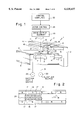
- FIG. 1 is a schematic and diagrammatic rear, top and side perspective view of the device according to the invention.
- FIG. 2 is an enlarged fragmentary side elevational view of FIG. 1, showing diagrammatically an electromagnetic linear drive forming part of the invention
- FIG. 3 is a block diagram of the control for the linear drive
- FIG. 4 is a fragmentary diagrammatic side elevational view of FIG. 1, showing a sheet feeder with a feeding table;
- FIG. 5 is a diagrammatic side elevational view of another embodiment of the sheet feeder followed by a printing press without any feeding table;
- FIG. 6 is a plot diagram showing a characteristic curve for the speed of the electromagnetic linear drive mechanism
- FIG. 7 is a plot diagram showing a characteristic curve for the speed of the electromagnetic linear drive provided with a spring damper stop element.
- FIG. 8 is a fragmentary diagrammatic top plan view of FIG. 1 showing another embodiment of the invention which includes a device for pivoting the electromagnetic linear drive.
- a sheet feeder 1 for a sheet-processing machine such as a printing press, in particular, having a frame 2, whereon a first crossbar or traverse 3 is secured for the purpose of holding auxiliary elements thereon for assisting in the separation of a sheet 4 from a sheet pile 6.
- auxiliary elements are, for example, loosening blowers 7 and 8 and a feeler or sensing foot 9 for ascertaining the exact height of the sheet pile and for controlling the tracking thereof.
- the linear drive 12 extends from one end of the sheet pile 6, in a direction towards the printing press, i.e., into the plane of FIG. 1, over a distance which is at least equal to the format length of the sheets to be processed.
- the linear drive 12 is made up essentially of a rail-like guide 11 and a carriage 19 (note FIG. 2) which is displaceable in the guide 11.
- the guide 11 is a horizontally disposed U-shaped profile member, which is secured by a bottom face 13 thereof to the crossbar 10 and, as shown in FIG.
- a north pole N of a permanent magnet 17 in the leg 14 is spaced from an opposite south pole S in the leg 16, and the reverse, while within either leg 14 or 16 itself, side-by-side north and south poles alternate N-S-N-S and so forth.
- a magnetic field M is generated between the legs 14 and 16 by the permanent magnets 17.
- the carriage 19 is shown provided with a coil 20 which is secured to a first leg 18 of a second, likewise horizontal U-shaped profile.
- a second leg 21 of this second U-shaped profile carries a combined lifting and dragging suction unit 22.
- the first leg 18 of the second U-shaped profile is supported between the legs 14 and 16 of the first U-shaped profile so as to be displaceable in and counter to the sheet transport direction and is secured against falling out at the side by a dovetail guide 23.
- the coil 20 Via a control line 27, the coil 20 is controlled by a drive output element 28, which is connected to a motor control 29.
- the lifting and dragging suction unit 22 is connected to a suction supply source 26 by a supply line 24.
- the loosening blowers 7 and 8 and a non-illustrated blower on the feeler foot 9 communicate via a supply line 31 with a blast or blown air source 32.
- the motor control 29 receives control commands from a control computer 33. Amongst other things, the blast air and the supply of suction for the sheet feeder 1 are controlled by the control computer 33. From a number of parameters and from a characteristic curve or algorithm stored in memory in the form of a closed-loop control circuit 34, the control computer 33, amongst other tasks, determines the control current I for the electromagnetic linear drive mechanism 12.
- the parameters required to calculate the control current I are the printing press speed n DM and the machine angle ⁇ DM for the printing press from the incremental encoder 30, and the actual position value ⁇ ist of the carriage 19.
- the actual position value ⁇ ist is read from a linear scale 35, which is disposed on the dovetail guide 23.
- the desired or nominal-value parameters, such as the desired position value ⁇ soll , the desired speed value n soll a and the desired acceleration value a soll for the carriage 19 and the coil 20, respectively, are furnished by the characteristic curve 37.
- a stop 41 is provided which is disposed by a damper-spring system on the feeder frame 2, in particular, in the guide of the linear drive mechanism 12.
- the device according to the invention can be employed in various general types of sheet feeder systems.
- FIG. 4 illustrates the application of the electromagnetic linear drive mechanism 12 in a separating or singling device which delivers the sheets 4 to a suction belt table 42.
- the respective sheet 4 in the region of the trailing edge thereof, is gripped by suction and lifted by a combined lifting and dragging sucker or suction device 22 and transported in synchronism with the operating cycle of the printing press, and in accordance with the transport speed of the suction belt table 42, respectively, to front lays 43 which have been provided.
- the sheet 4 is aligned and then transferred by suitably provided pregrippers 44 to the cylinders of the printing press.
- the takeover point namely, the position of the lifting suction device upon separation of the sheet 4 from the sheet pile 6, can be input into the control computer 33 by a keyboard 36, as a function of or in accordance with the format length of the sheet to be processed.
- FIG. 5 illustrates the application of the electromagnetic linear drive mechanism 12 in a sheet feeder 1 wherein the sheets 4 are separated by a lifting suction device from the sheet pile 6 and are transferred in the raised position thereof to the feeder elements of the linear drive mechanism 12, which then transfers them directly to a gripper 46 of the printing press.
- the feeder elements of the linear drive mechanism 12 are constructed as drag suction devices or grippers.
- linear drive mechanism 12 be equipped, in accordance with FIG. 4, with drag suction devices, which take over the separated sheets in the raised state, for example, from a lifting suction device system.
- linear drive mechanism it is naturally also conceivable for the linear drive mechanism to be equipped, in accordance with FIG. 5, with a combined lifting and drag sucker or suction device, so that an additional lifting unit for separating the sheet from the sheet pile can be dispensed with.
- the electromagnetic linear drive mechanism 12 functions as follows:
- the carriage 19 is stopped in a receiving position, as a function of or in accordance with the format length of the sheet 4 to be processed.
- the top sheet 4 on the sheet pile 6 is separated from the sheet pile 6 and raised by a separating element 22 (such as a jump-type suction device, for example).
- the carriage 19 with the feeder elements 22 disposed thereon is then accelerated to transfer speed.
- the transfer speed is kept constant over a transfer region until the transfer of the sheets 4 (for example, to a conveyor belt 42) has occurred.
- the carriage 19 is braked, stopped, and caused to execute a reverse motion by a reversal of the control of the motor current I.
- the carriage 19 is accelerated to a predetermined reverse speed and, upon attaining the maximum reverse speed, is braked down to a speed of zero.
- the carriage 19 is then at a standstill, and the feeder elements 22 are ready to receive the next sheet 4.
- a slide enhancer is provided between the carriage 19 and the guide 11, the sliding properties being improved thereby, for example, by coating the sliding surfaces with Teflon (tetrafluoroethylene) or “nano-ceramic".
- Pre-alignment of the sheet 4 to be transported can be accomplished, for example, by supporting the crossbar 11 on the frame 2 by an articulated connection 47 and, by employing an adjusting element 48 for pivoting the crossbar 11 horizontally.
- the control computer 33 also furnishes control signals for the magnitude of the pivoting motion and, for this purpose, is connected to non-illustrated suitable conventional sensor means for detecting respective sheets which are disposed in oblique positions.
- a method for transporting the sheet 4 consequently includes initially moving the sheet 4, which has been separated from the sheet pile 2 by the lifting device 22, counter to the provided transport direction to the printing press. Due to the foregoing features, whichever sheet 4 is on top of the sheet pile 6 can be released from the leading-edge stops, i.e., the stop flaps 39.
Landscapes
- Engineering & Computer Science (AREA)
- Mechanical Engineering (AREA)
- Sheets, Magazines, And Separation Thereof (AREA)
- Feeding Of Articles By Means Other Than Belts Or Rollers (AREA)
- Separation, Sorting, Adjustment, Or Bending Of Sheets To Be Conveyed (AREA)
- Delivering By Means Of Belts And Rollers (AREA)
- Supply, Installation And Extraction Of Printed Sheets Or Plates (AREA)
- Conveying Record Carriers (AREA)
Applications Claiming Priority (2)
| Application Number | Priority Date | Filing Date | Title |
|---|---|---|---|
| DE19653343 | 1996-12-20 | ||
| DE19653343A DE19653343A1 (de) | 1996-12-20 | 1996-12-20 | Vorrichtung zum Transport von Bogen, die von einem Bogenstapel vereinzelt worden sind |
Publications (1)
| Publication Number | Publication Date |
|---|---|
| US6135437A true US6135437A (en) | 2000-10-24 |
Family
ID=7815568
Family Applications (1)
| Application Number | Title | Priority Date | Filing Date |
|---|---|---|---|
| US08/996,370 Expired - Fee Related US6135437A (en) | 1996-12-20 | 1997-12-22 | Device and method for transporting sheets singly separated from a sheet pile |
Country Status (4)
| Country | Link |
|---|---|
| US (1) | US6135437A (fr) |
| EP (1) | EP0849200B1 (fr) |
| JP (1) | JP3805879B2 (fr) |
| DE (2) | DE19653343A1 (fr) |
Cited By (4)
| Publication number | Priority date | Publication date | Assignee | Title |
|---|---|---|---|---|
| US6450493B1 (en) * | 2000-12-07 | 2002-09-17 | Xerox Corporation | Image transfer apparatus shuttle feeder module |
| US6682065B2 (en) * | 2000-02-08 | 2004-01-27 | Meco Pak Aktiebolag | Device for feeding objects piece by piece |
| US20050093223A1 (en) * | 2003-10-30 | 2005-05-05 | Masayuki Kashiba | Sheet supplying device |
| US8468863B2 (en) | 2007-08-07 | 2013-06-25 | E.W. Menn Gmbh & Co. Kg | Profile-rolling machine |
Families Citing this family (6)
| Publication number | Priority date | Publication date | Assignee | Title |
|---|---|---|---|---|
| DE10013006B4 (de) * | 2000-03-16 | 2004-02-19 | Man Roland Druckmaschinen Ag | Vorrichtung für den Antrieb eines Vorgreifers |
| DE10040390A1 (de) * | 2000-08-18 | 2002-02-28 | Georg Geis Maschinenfabrik | Anlage zur Herstellung und fertigen Bearbeitung von Kunststoffteilen |
| DE10223350A1 (de) * | 2002-05-25 | 2003-12-04 | Kolbus Gmbh & Co Kg | Vorrichtung zum Vereinzeln und Zuführen des jeweils untersten Bogens aus einem Stapel |
| DE102004022229A1 (de) * | 2004-05-04 | 2005-12-01 | Mabeg Maschinenbau Gmbh & Co. Kg | Vorderkantenanleger |
| DE102004022233A1 (de) * | 2004-05-04 | 2005-12-01 | Mabeg Maschinenbau Gmbh & Co. Kg | Vorderkantenanleger |
| DE102008054813A1 (de) * | 2008-12-17 | 2010-06-24 | Koenig & Bauer Aktiengesellschaft | Vorrichtung zum Ausrichtung von Bogen |
Citations (17)
| Publication number | Priority date | Publication date | Assignee | Title |
|---|---|---|---|---|
| DE454704C (de) * | 1926-02-28 | 1928-01-14 | Julius Ameismaier | Selbsttaetige Bogenabhebe- und Zufuehrvorrichtung fuer Druckmaschinen |
| DE923132C (de) * | 1952-06-29 | 1955-02-03 | Mabeg Maschb G M B H | Vorrichtung zum Vereinzeln und zum Zufuehren von Bogen aus Papier usw. an Druck-, Lackier- und Falzmaschinen |
| DE1177652B (de) * | 1956-04-07 | 1964-09-10 | Georg Spiess Dr Ing | Bogenanlegevorrichtung mit zwei gemeinsam um eine pendelnd bewegte Achse schwenkbaren Saugduesen |
| US3466028A (en) * | 1966-06-24 | 1969-09-09 | Vidosa Sa | Apparatus for feeding sheets from a stack to a processing machine |
| DE2336387A1 (de) * | 1972-07-18 | 1974-02-07 | Ricoh Kk | Vorrichtung fuer die intermittierende zufuehrung von flaechenmaterial, insbesondere karten |
| DD114373A1 (fr) * | 1974-01-23 | 1975-08-05 | ||
| US4081723A (en) * | 1975-05-02 | 1978-03-28 | Veb Polygraph Leipzog Kombinat Fur Polygraphische Maschinen Und Ausrustungen | Printing machine |
| US4151447A (en) * | 1976-11-29 | 1979-04-24 | Papst-Motoren Kg | Linear motor |
| US4565478A (en) * | 1981-02-03 | 1986-01-21 | Svecia Silkscreen Maskiner Ab | Materials handling device |
| US4624617A (en) * | 1984-10-09 | 1986-11-25 | David Belna | Linear induction semiconductor wafer transportation apparatus |
| US4651984A (en) * | 1983-09-02 | 1987-03-24 | M.A.N.-Roland Druckmaschinen Aktiengesellschaft | Method of and apparatus for accurate-register sheet transport in a printing machine |
| DE3606178C1 (en) * | 1986-02-26 | 1987-07-16 | Lazar Peter | Process for separating sheets and sheet separator for carrying out this process |
| US4749921A (en) * | 1986-07-21 | 1988-06-07 | Anwar Chitayat | Linear motor with non-magnetic armature |
| US5086729A (en) * | 1988-06-13 | 1992-02-11 | Asahi Glass Company Ltd. | Vacuum processing apparatus and transportation system thereof |
| DE19511296A1 (de) * | 1995-03-28 | 1996-10-02 | Gremser Masch Franz | Vorrichtung zum Anheben und Abtransportieren flächiger Gegenstände |
| US5595381A (en) * | 1993-09-17 | 1997-01-21 | Man Roland Druckmaschinen Ag | Sheet feeder unit |
| US5793128A (en) * | 1995-03-31 | 1998-08-11 | Minolta Co., Ltd. | Encoder and motor with an encoder |
Family Cites Families (2)
| Publication number | Priority date | Publication date | Assignee | Title |
|---|---|---|---|---|
| JPS59114242A (ja) * | 1982-12-16 | 1984-07-02 | Canon Inc | シ−ト搬送装置 |
| JPS63101241A (ja) * | 1986-10-20 | 1988-05-06 | Hitachi Ltd | 媒体搬送装置 |
-
1996
- 1996-12-20 DE DE19653343A patent/DE19653343A1/de not_active Withdrawn
-
1997
- 1997-12-01 DE DE59704293T patent/DE59704293D1/de not_active Expired - Lifetime
- 1997-12-01 EP EP97121049A patent/EP0849200B1/fr not_active Expired - Lifetime
- 1997-12-22 US US08/996,370 patent/US6135437A/en not_active Expired - Fee Related
- 1997-12-22 JP JP35317197A patent/JP3805879B2/ja not_active Expired - Fee Related
Patent Citations (17)
| Publication number | Priority date | Publication date | Assignee | Title |
|---|---|---|---|---|
| DE454704C (de) * | 1926-02-28 | 1928-01-14 | Julius Ameismaier | Selbsttaetige Bogenabhebe- und Zufuehrvorrichtung fuer Druckmaschinen |
| DE923132C (de) * | 1952-06-29 | 1955-02-03 | Mabeg Maschb G M B H | Vorrichtung zum Vereinzeln und zum Zufuehren von Bogen aus Papier usw. an Druck-, Lackier- und Falzmaschinen |
| DE1177652B (de) * | 1956-04-07 | 1964-09-10 | Georg Spiess Dr Ing | Bogenanlegevorrichtung mit zwei gemeinsam um eine pendelnd bewegte Achse schwenkbaren Saugduesen |
| US3466028A (en) * | 1966-06-24 | 1969-09-09 | Vidosa Sa | Apparatus for feeding sheets from a stack to a processing machine |
| DE2336387A1 (de) * | 1972-07-18 | 1974-02-07 | Ricoh Kk | Vorrichtung fuer die intermittierende zufuehrung von flaechenmaterial, insbesondere karten |
| DD114373A1 (fr) * | 1974-01-23 | 1975-08-05 | ||
| US4081723A (en) * | 1975-05-02 | 1978-03-28 | Veb Polygraph Leipzog Kombinat Fur Polygraphische Maschinen Und Ausrustungen | Printing machine |
| US4151447A (en) * | 1976-11-29 | 1979-04-24 | Papst-Motoren Kg | Linear motor |
| US4565478A (en) * | 1981-02-03 | 1986-01-21 | Svecia Silkscreen Maskiner Ab | Materials handling device |
| US4651984A (en) * | 1983-09-02 | 1987-03-24 | M.A.N.-Roland Druckmaschinen Aktiengesellschaft | Method of and apparatus for accurate-register sheet transport in a printing machine |
| US4624617A (en) * | 1984-10-09 | 1986-11-25 | David Belna | Linear induction semiconductor wafer transportation apparatus |
| DE3606178C1 (en) * | 1986-02-26 | 1987-07-16 | Lazar Peter | Process for separating sheets and sheet separator for carrying out this process |
| US4749921A (en) * | 1986-07-21 | 1988-06-07 | Anwar Chitayat | Linear motor with non-magnetic armature |
| US5086729A (en) * | 1988-06-13 | 1992-02-11 | Asahi Glass Company Ltd. | Vacuum processing apparatus and transportation system thereof |
| US5595381A (en) * | 1993-09-17 | 1997-01-21 | Man Roland Druckmaschinen Ag | Sheet feeder unit |
| DE19511296A1 (de) * | 1995-03-28 | 1996-10-02 | Gremser Masch Franz | Vorrichtung zum Anheben und Abtransportieren flächiger Gegenstände |
| US5793128A (en) * | 1995-03-31 | 1998-08-11 | Minolta Co., Ltd. | Encoder and motor with an encoder |
Non-Patent Citations (2)
| Title |
|---|
| Japanese Patent Abstract No. 63 101241 (Sasaki), dated May 6, 1988. * |
| Japanese Patent Abstract No. 63-101241 (Sasaki), dated May 6, 1988. |
Cited By (5)
| Publication number | Priority date | Publication date | Assignee | Title |
|---|---|---|---|---|
| US6682065B2 (en) * | 2000-02-08 | 2004-01-27 | Meco Pak Aktiebolag | Device for feeding objects piece by piece |
| US6450493B1 (en) * | 2000-12-07 | 2002-09-17 | Xerox Corporation | Image transfer apparatus shuttle feeder module |
| US20050093223A1 (en) * | 2003-10-30 | 2005-05-05 | Masayuki Kashiba | Sheet supplying device |
| US7198264B2 (en) * | 2003-10-30 | 2007-04-03 | Horizon International Inc. | Sheet supplying device |
| US8468863B2 (en) | 2007-08-07 | 2013-06-25 | E.W. Menn Gmbh & Co. Kg | Profile-rolling machine |
Also Published As
| Publication number | Publication date |
|---|---|
| EP0849200A3 (fr) | 1998-12-23 |
| JPH10194484A (ja) | 1998-07-28 |
| EP0849200B1 (fr) | 2001-08-16 |
| JP3805879B2 (ja) | 2006-08-09 |
| DE19653343A1 (de) | 1998-06-25 |
| DE59704293D1 (de) | 2001-09-20 |
| EP0849200A2 (fr) | 1998-06-24 |
Similar Documents
| Publication | Publication Date | Title |
|---|---|---|
| US4588184A (en) | Method of flow-feeding sheets | |
| US6240843B1 (en) | Sheet transport system for a rotary printing press | |
| US8066282B2 (en) | Apparatus for feeding and aligning sheets fed to a processing machine, in particular a printing machine | |
| US8690151B2 (en) | Method and apparatus for separating out printed products from a stack | |
| US7011305B2 (en) | Device and method for aligning sheets | |
| US5103733A (en) | Printing machine with continuous sheet feed mechanism | |
| US5131647A (en) | Sheet feeder for printing machines and the like | |
| US8196307B2 (en) | Register insertion apparatus | |
| US6135437A (en) | Device and method for transporting sheets singly separated from a sheet pile | |
| US6155555A (en) | Device for supplying air to electromagnetic linearly driven lifters air consumers of a sheet-processing machine | |
| JP2017048018A (ja) | 物品仕分装置 | |
| JPH04226240A (ja) | 書類回転装置 | |
| JPH0637256B2 (ja) | 包装機、製本機等のフイ−ダに適した、折り丁、シ−ト及び類似の製品のロ−ダ | |
| US8556252B2 (en) | Device and method to supply print products to a processing section | |
| US6923119B1 (en) | Sheet transport system for a rotary printing press | |
| US5527027A (en) | Device and method for separating and aligning sheets in a sheet feeder of a printing machine | |
| US20240246786A1 (en) | Printing press comprising a non-impact printing device | |
| GB2273490A (en) | Laterally registering sheets | |
| US4227685A (en) | Sheet feeding apparatus, particularly for rotary printing machines | |
| US6505831B2 (en) | Method for the proper alignment of sheets | |
| JP2886129B2 (ja) | 枚葉紙給紙装置 | |
| JPH1191987A (ja) | 電気リニアードライブを有する郵便室コンベアシステム | |
| SE417942B (sv) | Forfarande och anordning for front- och sidokantsjustering av ett forsta med overlappning pa ett ileggningsbord med sido- och frontmerken transporterat ark | |
| US5915682A (en) | Sheet feeder system and method for individually separating sheets | |
| JPH0867393A (ja) | シート状製品を直線的に搬送するための装置 |
Legal Events
| Date | Code | Title | Description |
|---|---|---|---|
| AS | Assignment |
Owner name: HEIDELBERGER DRUCKMASCHINEN AG, GERMANY Free format text: ASSIGNMENT OF ASSIGNORS INTEREST;ASSIGNORS:MAASS, JURGEN;WAGENSOMMER, BERHARD;KRUGER, MICHAEL;AND OTHERS;REEL/FRAME:011060/0239;SIGNING DATES FROM 19980108 TO 19980202 |
|
| FEPP | Fee payment procedure |
Free format text: PAYOR NUMBER ASSIGNED (ORIGINAL EVENT CODE: ASPN); ENTITY STATUS OF PATENT OWNER: LARGE ENTITY |
|
| FPAY | Fee payment |
Year of fee payment: 4 |
|
| FPAY | Fee payment |
Year of fee payment: 8 |
|
| REMI | Maintenance fee reminder mailed | ||
| LAPS | Lapse for failure to pay maintenance fees | ||
| STCH | Information on status: patent discontinuation |
Free format text: PATENT EXPIRED DUE TO NONPAYMENT OF MAINTENANCE FEES UNDER 37 CFR 1.362 |
|
| FP | Lapsed due to failure to pay maintenance fee |
Effective date: 20121024 |