US5808238A - Multiple-cable power for transmission line system - Google Patents
Multiple-cable power for transmission line system Download PDFInfo
- Publication number
- US5808238A US5808238A US08/752,397 US75239796A US5808238A US 5808238 A US5808238 A US 5808238A US 75239796 A US75239796 A US 75239796A US 5808238 A US5808238 A US 5808238A
- Authority
- US
- United States
- Prior art keywords
- transmission line
- overhead transmission
- outer periphery
- cable power
- line system
- Prior art date
- Legal status (The legal status is an assumption and is not a legal conclusion. Google has not performed a legal analysis and makes no representation as to the accuracy of the status listed.)
- Expired - Fee Related
Links
Images


Classifications
-
- H—ELECTRICITY
- H02—GENERATION; CONVERSION OR DISTRIBUTION OF ELECTRIC POWER
- H02G—INSTALLATION OF ELECTRIC CABLES OR LINES, OR OF COMBINED OPTICAL AND ELECTRIC CABLES OR LINES
- H02G7/00—Overhead installations of electric lines or cables
- H02G7/20—Spatial arrangements or dispositions of lines or cables on poles, posts or towers
Definitions
- the present invention relates to a multiple-cable power transmission line system designed to reduce noise caused by wind and to suppress the generation of audible noise induced by corona discharge.
- a plurality of such transmission lines for example, four transmission lines, are extended to thereby constitute a multiple-cable power transmission line system.
- a multiple-cable power transmission line system including a plurality of overhead transmission lines each having a ridge on its outer periphery
- the heights of the ridges of the individual overhead transmission lines are set to an identical value most suited to prevent noise from being caused by wind.
- each overhead transmission line of the multiple-cable power transmission line system has a ridge on its outer periphery, corona discharge is liable to occur at the ridges of overhead transmission lines located closer to the earth ground, thereby causing the possibility of radio interference etc.
- An object of the present invention is to provide a multiple-cable power transmission line system capable of suppressing the occurrence of corona discharge at the ridges of overhead transmission lines located closer to the earth ground.
- a multiple-cable power transmission line system including a plurality of overhead transmission lines each having a ridge on an outer periphery thereof, wherein the relation L E ⁇ L OT is fulfilled, where L E is an outer periphery-to-crest height of the ridge of an overhead transmission line which is located closer to the earth ground, and L OT is an outer periphery-to-crest height of the ridge of another overhead transmission line.
- the outer periphery-to-crest heights L E and L OT of the ridges satisfy the relation 0.1 ⁇ L E /L OT ⁇ 1.0.
- a multiple-cable power transmission line system including a plurality of overhead transmission lines each having a ridge member on an outer periphery thereof, wherein the relation P E >P OT is fulfilled, where P E is a winding pitch at which the ridge member is wound around an overhead transmission line located closer to the earth ground, and P OT is a winding pitch at which the ridge member is wound around another overhead transmission line.
- the winding pitches P E and P OT satisfy the relation 0.5 ⁇ P OT /P E ⁇ 1.0.
- the outer periphery-to-crest height L E of the ridge of the overhead transmission line located closer to the earth ground is smaller than the outer periphery-to-crest height L OT of the ridges of the other overhead transmission lines. Consequently, corona discharge scarcely occurs at the ridge of the overhead transmission line located closer to the earth ground.
- the winding pitch P E at which the ridge member is wound around the overhead transmission line located closer to the earth ground is greater than the winding pitch P OT at which the ridge member is wound around the other overhead transmission line.
- the number of turns of the ridge member per unit length is small, whereby the frequency of occurrences of corona discharge is lessened.
- FIG. 1 a sectional view showing a first embodiment according to the present invention
- FIG. 2 is a sectional view showing another embodiment of the present invention.
- FIG. 3 is a sectional view showing still another embodiment of the present invention.
- FIG. 4 is a sectional view showing a further embodiment of the present invention.
- FIG.5 is a sectional view showing an example of an overhead transmission line used in a multiple-cable power transmission line system of the present invention
- FIG. 6 is a sectional view showing another example of the overhead transmission line used in the multiple-cable power transmission line system of the present invention.
- FIG. 7 is a sectional view showing still another example of the overhead transmission line used in the multiple-cable power transmission line system of the present invention.
- FIG. 8 is a potential gradient characteristic diagram showing the results of measurement of corona hum noise levels observed in the multiple-cable power transmission line system according to the present invention and a conventional multiple-cable power transmission line system;
- FIG. 9 is a schematic side view of a multiple-cable power transmission line system according to still another embodiment of the present invention.
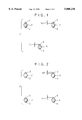
- FIG. 1 illustrates the case where the present invention is applied to an inverted-triangle arrangement of a three-cable power transmission line system 1 in which three overhead transmission lines 2 and 4 are arranged in the form of an inverted triangle.
- Each overhead transmission line 2, 4 has a pair of ridges 3, 5 formed on its diametrically opposite sides.
- the ridges 3, 5 are formed by winding spiral rods of polyamide resin, fluorine-contained resin or the like around the outer periphery of the overhead transmission line 2, 4, or by previously twining ridging wires around the outer periphery of the overhead transmission line 2, 4.
- the ridges 5 of the overhead transmission line 4 which is located closer to the earth ground have an outer periphery-to-crest height L E smaller than the outer periphery-to-crest height L OT of the ridges 3 of the other overhead transmission lines 2.
- the outer periphery-to-crest heights L E and L OT of the ridges 5 and 3 are set to values satisfying the relation of 0.1 ⁇ L E /L OT ⁇ 1.0. If L E /L OT is smaller than 0.1, corona discharge of the overhead transmission line 4 located closer to the earth ground can be suppressed, but the effect of reducing wind-induced noise cannot be expected.
- the ratio of the ridge height L E to the ridge height L OT is set to a value falling within the range of 0.25 ⁇ L E /L OT ⁇ 0.6.
- Each of the overhead transmission lines 2 and 4 comprises several to several tens of wires stranded together, though not clearly shown in FIGS. 1 to 4.
- the outer periphery-to-crest height of the ridges of the individual overhead transmission lines is set to a value most suited to prevent noise induced by wind.
- the three-cable power transmission line system 1 employs an arrangement wherein the ridges 3 of the overhead transmission lines 2 are greater in height than the ridges 5 of the overhead transmission line 4. If the overhead transmission line 2 of which the ridges 3 are greater in height than the ridges 5 is located closer to the earth ground, in place of the overhead transmission line 4, corona discharge occurs at the ridges 3.
- FIG. 2 illustrates the case where the present invention is applied to a four-cable power transmission line system 6.
- the four-cable power transmission line system 6 has a square or quadrilateral arrangement constituted by a total of four overhead transmission lines 2 and 4, that is, two upper overhead transmission lines 2 and two lower overhead transmission lines 4.
- These overhead transmission lines 2 and 4 are identical with the corresponding ones of the overhead transmission lines of the foregoing embodiment in that a pair of ridges 3, 5 are formed on diametrically opposite sides of each overhead transmission line, and that the outer periphery-to-crest height L E of the ridges 5 of the overhead transmission lines 4 located closer to the earth ground is smaller than the outer periphery-to-crest height L OT of the ridges 3 of the other overhead transmission lines 2.
- FIG. 3 illustrates the case where the present invention is applied to a six-cable power transmission line system 7.
- the six-cable power transmission line system 7 has a hexagonal arrangement constituted by a total of six overhead transmission lines 2 and 4, that is, four overhead transmission lines 2 and two overhead transmission lines 4.
- These overhead transmission lines 2 and 4 are identical with the corresponding ones of the overhead transmission lines of the foregoing embodiments in that a pair of ridges 3, 5 are formed on diametrically opposite sides of each overhead transmission line, and that the outer periphery-to-crest height L E of the ridges 5 of the overhead transmission lines 4 located closest to the earth ground is smaller than the outer periphery-to-crest height L OT of the ridges 3 of the other overhead transmission lines 2.
- FIG. 4 illustrates the case where the present invention is applied to an eight-cable power transmission line system 8.
- the eight-cable power transmission line system 8 has an octagonal arrangement constituted by a total of eight overhead transmission lines 2 and 4, that is, six overhead transmission lines 2 and two overhead transmission lines 4.
- These overhead transmission lines 2 and 4 are identical with the corresponding ones of the overhead transmission lines of the foregoing embodiments in that a pair of ridges 3, 5 are formed on diametrically opposite sides of each overhead transmission line, and that the outer periphery-to-crest height L E of the ridges 5 of the overhead transmission lines 4 located closest to the earth ground is smaller than the outer periphery-to-crest height L OT of the ridges 3 of the other overhead transmission lines 2.
- the outer periphery-to-crest height of the ridges 3 of the two overhead transmission lines 2 which are located at a lower level than center C may of course be set to a value smaller than the outer periphery-to-crest height of the ridges 3 of the other four overhead transmission lines 2 located at a higher level than center C.
- FIG. 5 shows an example; of an overhead transmission line 10 constituting the multiple-cable power transmission line system according to the present invention.
- the overhead transmission line 10 comprises a steel core 11 having steel wires twisted together, a plurality of aluminum wires 12 twined around the steel core 11, and a plurality of outermost wires 13 twined around the aluminum wires 12.
- a pair of ridges 14 are interposed between the outermost wires 13 so as to be located on diametrically opposite sides of the outermost layer constituted by the wires 13.
- Each ridge 14 comprises two large ridging wires 15 and a small ridging wire 16 interposed therebetween.
- FIGS. 6 and 7 show other examples of the overhead transmission line constituting the multiple-cable power transmission line system according to the present invention.
- identical reference numerals are used to denote identical elements corresponding to those of the overhead transmission line 10 shown in FIG. 5, and detailed description of such elements is omitted.
- ridges 21, 26 are arranged on diametrically opposite sides of a portion of the outermost layer constituted by a plurality of wires 13.
- each ridge 21 comprises a ridging wire 22 and two wires 23 arranged on opposite sides, respectively, of the ridging wire 22 and each having a surface 23a parallel to a plane containing the center (axis) of the overhead transmission line 20, and the ridging wires 22 and the wires 23 are twined, together with the outermost wires 13, to form the ridges 21.
- the ridges 21 are located inside the circular envelope of a cross section of the overhead transmission line 20. Consequently, corona discharge of the overhead transmission line 20 is reduced, thus improving the resistance characteristics to corona discharge, and also the load of wind pressure is small because the wind-receiving area is not increased. Further, the overhead transmission line 20 receives a smaller wind pressure when wind impinges thereupon obliquely, whereby galloping, which is a low-frequency vibration with an amplitude as large as 5 to 10 m, can advantageously be prevented.
- each ridge 26 comprises three ridging wires 27 and two wires 28 arranged on each side of the ridging wires 27 and each having a surface 28a parallel to a plane containing the center (axis) of the overhead transmission line 25, and the ridging wires 27 and the wires 28 are twined, together with the outermost wires 13, to form the ridges 26.
- the ridges 26 of this overhead transmission line 25 have an outer periphery-to-crest height L 2 smaller than a ridge height L 1 of the ridging wires 15 of the overhead transmission line 10 shown in FIG. 5 (L 2 ⁇ L 1 ).
- FIG. 8 is a potential gradient characteristic diagram showing the result of measurement of corona hum noise observed in an eight-cable power transmission line system 8 (FIG. 4) using the overhead transmission lines 10 whose ridging wires 15 have the ridge height L 1 as shown in FIG. 5 and the overhead transmission lines 25 whose ridging wires 27 have a smaller ridge height L 2 than the ridging wires 15 as shown in FIG. 7.
- the overhead transmission line 25 shown in FIG. 7 was used for each of the overhead power transmission lines 2, 4 located at a lower level than center C
- the overhead transmission line 10 shown in FIG. 5 was used for each of the overhead transmission lines 2 located at a higher level than center C.
- each overhead transmission line 10 had an outer periphery-to-crest height L 1 of 2.5 mm
- each transmission line 10 had an outside diameter D 01 , of 38.4 mm
- the ridges 26 of each overhead transmission line 25 had an outer periphery-to-crest height L 2 of 1.7 mm
- each overhead transmission line 25 had an outside diameter D 02 of 38.4 mm.
- the measurement result is indicated by solid line A in FIG. 8.
- one-dot-chain line B indicates the measurement result obtained by the conventional eight-cable power transmission line system 8 using only the overhead transmission lines 10 shown in FIG. 5
- dashed line C indicates the measurement result obtained by the eight-cable power transmission line system 8 using only the overhead transmission lines 20 shown in FIG. 6.
- the overhead transmission lines 10 and 25 used had the same size as mentioned above, and the overhead transmission lines 20 used had an outside diameter D 01 of 38.4 mm.
- the overhead transmission line 10 shown in FIG. 5 had a nominal cross-sectional area of 940 mm 2
- the overhead transmission line 20 shown FIG. 6 had a nominal cross-sectional area of 930 mm 2
- the overhead transmission line 25 shown in FIG. 7 had a cross-sectional area equivalent to 930 mm 2 .
- the corona hum noise could be reduced by 4 to 10 dB (A) over the range of 14 to 17 (kV/cm) in which the problem of corona hum noise is conspicuous, compared with the conventional multiple-cable power transmission line system (one-dot-chain line B).
- FIG. 9 illustrates a multiple-cable power transmission line system 30 including two overhead transmission lines 31 and 33 according to another embodiment of the present invention, and this embodiment is characterized in that a winding pitch P E of a ridge member 34 of the overhead transmission line 33 located closer to the earth ground is greater than a winding pitch P OT of a ridge member 32 of the other or upper overhead transmission line 31.
- the heights of the ridge members 32 and 34 need not be the same and may be different from each other.
- the winding pitch P E of the ridge member 34 of the overhead transmission line 33 which is located closer to the earth ground is made greater than the winding pitch P OT of the ridge member 32 of the other overhead transmission line 31, so that the number of turns of the ridge member 34 per unit length of the overhead transmission line 33 decreases. Consequently, the frequency of occurrences of corona discharge of the overhead transmission line 33 can be lessened, as compared with the overhead transmission line 31.
- the ridge members 32 and 34 are wound in such a manner that their winding pitches P OT and P E satisfy the relation of 0.5 ⁇ P OT /P E ⁇ 1.0. If P OT /P E is smaller than 0.5, the effect of reducing wind-induced noise by the ridge member 34 lessens because the winding pitch P E of the ridge member 34 is too large, or wind-induced noise is amplified by the ridge member 32 because the winding pitch P OT of the ridge member 32 is too small.
- the winding pitches P OT and P E are set to values satisfying the relation of 0.5 ⁇ P OT /P E ⁇ 0.7.
- the winding pitch of the ridge member of an overhead transmission line with a small ridge height may be set to a value greater than that of the ridge member of an overhead transmission line with a large ridge height.
- the ridges of the overhead transmission line(s) located closer to the earth ground have an outer periphery-to-crest height smaller than that of the ridges of the other overhead transmission lines, whereby the possibility of corona discharge occurring at the ridges can be lessened.
- the winding pitch of the ridge member of the overhead transmission line which is located closer to the earth ground is greater than that of the ridge member of the other overhead transmission lines.
- the number of turns of the ridge member per unit length is decreased, so that the frequency of occurrences of corona discharge can be reduced.
Landscapes
- Non-Insulated Conductors (AREA)
- Suspension Of Electric Lines Or Cables (AREA)
Applications Claiming Priority (2)
| Application Number | Priority Date | Filing Date | Title |
|---|---|---|---|
| JP7305744A JPH09147628A (ja) | 1995-11-24 | 1995-11-24 | 多導体送電線路 |
| JP7-305744 | 1995-11-24 |
Publications (1)
| Publication Number | Publication Date |
|---|---|
| US5808238A true US5808238A (en) | 1998-09-15 |
Family
ID=17948825
Family Applications (1)
| Application Number | Title | Priority Date | Filing Date |
|---|---|---|---|
| US08/752,397 Expired - Fee Related US5808238A (en) | 1995-11-24 | 1996-11-20 | Multiple-cable power for transmission line system |
Country Status (3)
| Country | Link |
|---|---|
| US (1) | US5808238A (de) |
| EP (1) | EP0776013A3 (de) |
| JP (1) | JPH09147628A (de) |
Cited By (6)
| Publication number | Priority date | Publication date | Assignee | Title |
|---|---|---|---|---|
| US6331677B1 (en) * | 1997-09-29 | 2001-12-18 | The Furukawa Electric Co., Ltd. | Overhead wire |
| US6753479B2 (en) * | 2000-03-17 | 2004-06-22 | Nippon Steel Corporation | Plated metal wire and method and apparatus for producing the same |
| US20160099090A1 (en) * | 2014-09-26 | 2016-04-07 | Jianping Huang | Energy Efficient Conductors With Reduced Thermal Knee Points and The Method of Manufacture Thereof |
| US11217364B2 (en) * | 2018-02-16 | 2022-01-04 | Essex Furukawa Magnet Wire Japan Co., Ltd. | Insulated wire, coil, and electric/electronic equipments |
| US11854721B2 (en) | 2022-03-28 | 2023-12-26 | Ts Conductor Corp. | Composite conductors including radiative and/or hard coatings and methods of manufacture thereof |
| US12394961B2 (en) | 2022-04-26 | 2025-08-19 | Ts Conductor Corp. | Earth wire including composite core and encapsulation layer and method of use thereof |
Families Citing this family (1)
| Publication number | Priority date | Publication date | Assignee | Title |
|---|---|---|---|---|
| ES2646966B2 (es) * | 2016-06-16 | 2018-04-17 | Universidad De Sevilla | Sistema compacto de transporte en corriente alterna multicircuito |
Citations (8)
| Publication number | Priority date | Publication date | Assignee | Title |
|---|---|---|---|---|
| JPS49101876A (de) * | 1973-02-02 | 1974-09-26 | ||
| JPS5096603A (de) * | 1973-12-27 | 1975-07-31 | ||
| JPH02311119A (ja) * | 1989-05-25 | 1990-12-26 | Hitachi Cable Ltd | 多導体送電線の風騒音対策方法 |
| JPH0378413A (ja) * | 1989-08-18 | 1991-04-03 | Hitachi Cable Ltd | 低コロナ騒音型低風音電線 |
| JPH04104404A (ja) * | 1990-08-24 | 1992-04-06 | Furukawa Electric Co Ltd:The | 低風音多導体送電線 |
| JPH04126306A (ja) * | 1990-09-17 | 1992-04-27 | Furukawa Electric Co Ltd:The | 低風音多導体送電線およびその延線方法 |
| JPH04253107A (ja) * | 1991-01-29 | 1992-09-08 | Furukawa Electric Co Ltd:The | 低風音電線 |
| JPH04253108A (ja) * | 1991-01-29 | 1992-09-08 | Furukawa Electric Co Ltd:The | 低風音電線 |
-
1995
- 1995-11-24 JP JP7305744A patent/JPH09147628A/ja active Pending
-
1996
- 1996-11-20 US US08/752,397 patent/US5808238A/en not_active Expired - Fee Related
- 1996-11-21 EP EP96118683A patent/EP0776013A3/de not_active Ceased
Patent Citations (9)
| Publication number | Priority date | Publication date | Assignee | Title |
|---|---|---|---|---|
| JPS49101876A (de) * | 1973-02-02 | 1974-09-26 | ||
| JPS5096603A (de) * | 1973-12-27 | 1975-07-31 | ||
| CA1038881A (en) * | 1973-12-27 | 1978-09-19 | Yoshiyuki Takagi | Method and apparatus for preparing edible oil |
| JPH02311119A (ja) * | 1989-05-25 | 1990-12-26 | Hitachi Cable Ltd | 多導体送電線の風騒音対策方法 |
| JPH0378413A (ja) * | 1989-08-18 | 1991-04-03 | Hitachi Cable Ltd | 低コロナ騒音型低風音電線 |
| JPH04104404A (ja) * | 1990-08-24 | 1992-04-06 | Furukawa Electric Co Ltd:The | 低風音多導体送電線 |
| JPH04126306A (ja) * | 1990-09-17 | 1992-04-27 | Furukawa Electric Co Ltd:The | 低風音多導体送電線およびその延線方法 |
| JPH04253107A (ja) * | 1991-01-29 | 1992-09-08 | Furukawa Electric Co Ltd:The | 低風音電線 |
| JPH04253108A (ja) * | 1991-01-29 | 1992-09-08 | Furukawa Electric Co Ltd:The | 低風音電線 |
Non-Patent Citations (6)
| Title |
|---|
| Derwent English language Abstract of SU 1415 235 A. * |
| Derwent English-language Abstract of SU-1415-235-A. |
| Patent Abstracts of Japan, vol. 15, No. 250 (E 1082), Jun. 26, 1991 & JP 03 078413 A (Hitachi Cable Ltd.), Apr. 3, 1991. * |
| Patent Abstracts of Japan, vol. 15, No. 250 (E-1082), Jun. 26, 1991 & JP 03 078413 A (Hitachi Cable Ltd.), Apr. 3, 1991. |
| Patent Abstracts of Japan, vol. 16, No. 389 (E 1250), Aug. 19, 1992 & JP 04 126306 A (Furukawa Electric Co., Ltd.), Apr. 27, 1992. * |
| Patent Abstracts of Japan, vol. 16, No. 389 (E-1250), Aug. 19, 1992 & JP 04 126306 A (Furukawa Electric Co., Ltd.), Apr. 27, 1992. |
Cited By (8)
| Publication number | Priority date | Publication date | Assignee | Title |
|---|---|---|---|---|
| US6331677B1 (en) * | 1997-09-29 | 2001-12-18 | The Furukawa Electric Co., Ltd. | Overhead wire |
| US6753479B2 (en) * | 2000-03-17 | 2004-06-22 | Nippon Steel Corporation | Plated metal wire and method and apparatus for producing the same |
| US20160099090A1 (en) * | 2014-09-26 | 2016-04-07 | Jianping Huang | Energy Efficient Conductors With Reduced Thermal Knee Points and The Method of Manufacture Thereof |
| US9633766B2 (en) * | 2014-09-26 | 2017-04-25 | Jianping Huang | Energy efficient conductors with reduced thermal knee points and the method of manufacture thereof |
| US11217364B2 (en) * | 2018-02-16 | 2022-01-04 | Essex Furukawa Magnet Wire Japan Co., Ltd. | Insulated wire, coil, and electric/electronic equipments |
| US11854721B2 (en) | 2022-03-28 | 2023-12-26 | Ts Conductor Corp. | Composite conductors including radiative and/or hard coatings and methods of manufacture thereof |
| US12142399B2 (en) | 2022-03-28 | 2024-11-12 | Ts Conductor Corp. | Composite conductors including radiative and/or hard coatings and methods of manufacture thereof |
| US12394961B2 (en) | 2022-04-26 | 2025-08-19 | Ts Conductor Corp. | Earth wire including composite core and encapsulation layer and method of use thereof |
Also Published As
| Publication number | Publication date |
|---|---|
| EP0776013A2 (de) | 1997-05-28 |
| EP0776013A3 (de) | 1997-08-27 |
| JPH09147628A (ja) | 1997-06-06 |
Similar Documents
| Publication | Publication Date | Title |
|---|---|---|
| US5808238A (en) | Multiple-cable power for transmission line system | |
| US20010017219A1 (en) | Overhead cable | |
| US20020036092A1 (en) | Overhead cable | |
| JP2851074B2 (ja) | 多導体送電線路 | |
| JP2945149B2 (ja) | 低風音電線 | |
| JP2945150B2 (ja) | 低風音電線 | |
| JPH04126306A (ja) | 低風音多導体送電線およびその延線方法 | |
| JPS6329490B2 (de) | ||
| JP2526658B2 (ja) | 多導体送電線の風音対策方法 | |
| JP2583300B2 (ja) | 低コロナ低風騒音電線 | |
| JP2851142B2 (ja) | 超高圧送電線 | |
| JP2959884B2 (ja) | 低風音型撚線導体 | |
| JP3191913B2 (ja) | 架空電線 | |
| JP2862984B2 (ja) | 多導体送電線路 | |
| JP2942438B2 (ja) | 低騒音電線 | |
| JPH07282633A (ja) | 緩み防止型架空電線 | |
| JPH05242734A (ja) | ギャロッピング防止型架空送電線 | |
| JP2585927Y2 (ja) | 低風音低an電線 | |
| JPH04104404A (ja) | 低風音多導体送電線 | |
| JPH077836A (ja) | 電線の風騒音防止装置取付け方法 | |
| JP2605688Y2 (ja) | 光ファイバ内蔵型架空地線 | |
| JPS6353763B2 (de) | ||
| JPS59194308A (ja) | 低騒音電線 | |
| JPH0135446B2 (de) | ||
| JPH07130222A (ja) | 低風騒音低コロナ騒音架空電線 |
Legal Events
| Date | Code | Title | Description |
|---|---|---|---|
| AS | Assignment |
Owner name: FURUKAWA ELECTRIC CO., LTD. THE, JAPAN Free format text: ASSIGNMENT OF ASSIGNORS INTEREST;ASSIGNORS:MUNAKATA, TAKEO;KATOH, JUN;SHINHARA, TAKASHI;REEL/FRAME:008331/0173 Effective date: 19961105 |
|
| FEPP | Fee payment procedure |
Free format text: PAYOR NUMBER ASSIGNED (ORIGINAL EVENT CODE: ASPN); ENTITY STATUS OF PATENT OWNER: LARGE ENTITY |
|
| REMI | Maintenance fee reminder mailed | ||
| LAPS | Lapse for failure to pay maintenance fees | ||
| STCH | Information on status: patent discontinuation |
Free format text: PATENT EXPIRED DUE TO NONPAYMENT OF MAINTENANCE FEES UNDER 37 CFR 1.362 |
|
| FP | Lapsed due to failure to pay maintenance fee |
Effective date: 20020915 |