US5377971A - Air-flow generating device for a sheet delivery of a sheet-fed printing machine - Google Patents
Air-flow generating device for a sheet delivery of a sheet-fed printing machine Download PDFInfo
- Publication number
- US5377971A US5377971A US08/050,709 US5070993A US5377971A US 5377971 A US5377971 A US 5377971A US 5070993 A US5070993 A US 5070993A US 5377971 A US5377971 A US 5377971A
- Authority
- US
- United States
- Prior art keywords
- air
- sheet
- delivery apparatus
- sheet delivery
- volume chamber
- Prior art date
- Legal status (The legal status is an assumption and is not a legal conclusion. Google has not performed a legal analysis and makes no representation as to the accuracy of the status listed.)
- Expired - Fee Related
Links
Images


Classifications
-
- B—PERFORMING OPERATIONS; TRANSPORTING
- B65—CONVEYING; PACKING; STORING; HANDLING THIN OR FILAMENTARY MATERIAL
- B65H—HANDLING THIN OR FILAMENTARY MATERIAL, e.g. SHEETS, WEBS, CABLES
- B65H29/00—Delivering or advancing articles from machines; Advancing articles to or into piles
- B65H29/24—Delivering or advancing articles from machines; Advancing articles to or into piles by air blast or suction apparatus
- B65H29/245—Air blast devices
- B65H29/246—Air blast devices acting on stacking devices
- B65H29/247—Air blast devices acting on stacking devices blowing on upperside of the sheet
-
- B—PERFORMING OPERATIONS; TRANSPORTING
- B65—CONVEYING; PACKING; STORING; HANDLING THIN OR FILAMENTARY MATERIAL
- B65H—HANDLING THIN OR FILAMENTARY MATERIAL, e.g. SHEETS, WEBS, CABLES
- B65H2801/00—Application field
- B65H2801/03—Image reproduction devices
- B65H2801/21—Industrial-size printers, e.g. rotary printing press
Definitions
- the invention relates to a sheet delivery for a sheet-processing machine, more particularly, a sheet-fed printing machine having a sheet-conveying device for conveying sheets successively to a device for receiving a pile of the sheets, an air-flow generating device being disposed above the sheet pile-receiving device for facilitating with air sheet-deposition onto the pile.
- Sheet deliveries of conventional sheet-fed printing machines have a delivery gripper system guiding the printed sheets to a sheet pile (delivery pile).
- a delivery gripper system guiding the printed sheets to a sheet pile (delivery pile).
- an air-generating device which is disposed above a device for receiving the sheet pile (a delivery table, paper stops, and so forth), by which the sheets, released by the grippers of the delivery gripper system and delayed by means of a sheet braking device, are subjected to air for the purpose of increasing the velocity of the descent of the sheets which are being deposited.
- Such an air-flow generating device is disclosed in German Published Non-Prosecuted Patent Application (DE-OS) 34 13 179 as having several blowers which are distributed over a maximally possible sheet format area and which are activated in accordance with the demand.
- the rotary speeds of the individual blowers or fans may be adjusted in accordance with the intensity of the respective desired air flow.
- the air-flow generating device heretofore known from the German patent application fails to meet adequately the different requirements dependent upon paper thickness, ink application, subject or motif formation, printing format, and so forth; in particular, at high printing speeds, the limits of such systems are readily revealed.
- a sheet delivery for a sheet-processing machine having a sheet-conveying device for successively conveying sheets to a device for receiving a sheet pile thereon, comprising a device disposed above the sheet-pile receiving device for generating an air flow to facilitate with air a depositing of the sheets upon the pile-receiving device, the air-flow generating device having an air-supplied air-volume chamber having a basal surface and formed with outlet openings distributed over the basal surface thereof, the basal surface having an area corresponding approximately to a maximum sheet format.
- the inventive air-volume chamber represents a material construction simplification in comparison with the conventional complex state-of-the-art arrangement of blowers, with air-blast or blowing-air pipes disposed between the blowers.
- the air-volume chamber may be supplied with air by the air-pressure device which is always available in sheet-fed printing machines, or by a separate central compressor or blower unit. Because the basal surface of the air-volume chamber corresponds approximately to the maximally possible sheet format of the respective sheet-fed printing machine, it is possible always to deposit or deliver sheets of any sheet format, even maximum sheet sizes, exactly and rapidly.
- covering means are included for sealing at least some of the outlet openings so as to adjust air-flow intensity and/or air diffusion of air escaping from the air-volume chamber.
- the covering means permits the respective sheet to be concretely blown-on independently of the sheet format and/or the motif or subject thereof, and so forth. Wavy regions of the sinking or descending sheets, for example, are able to be blown-on by partial air flows escaping through respective outlet openings, so that a sheet deposit or delivery in a stable position, for example, in a V position, is possible.
- the covering means it is possible, among other things, to adapt the air-escape range to the individual sheet sizes, which ensures a more accurate control and, moreover, lowers air consumption and the energy cost thereof. Adjusting to the respective print-job sheets takes only very little time and is not complicated, because only those outlet openings which are not needed to generate the air flow for sheet depositing or delivery have to be closed by the covering means.
- the air-volume chamber has a bottom wall formed with a basal surface, the outlet openings being formed in the bottom wall.
- the bottom wall is a perforated plate.
- the bottom wall is a plate formed with a multiplicity of round holes therein.
- the round-hole plate may correspond, for example, to German Industrial Norm (DIN) 24 041.
- the round-hole plate may be covered by an appropriate surface material; partial regions of the maximum sheet format corresponding to the basal surface may, for example, be sealed by covering plates or foils.
- the covering plates or foils may be laid on supporting grids or the like which are disposed at a given spaced distance from the bottom wall of the air-volume chamber so that the covering means may be received thereat. It is also conceivable to use adhesive foils which are stuck onto the basal surface wherein the outlet openings are formed, thereby sealing the respective outlet openings.
- the bottom wall is formed, at least in part, of ferromagnetic material.
- the covering means are a magnetic covering.
- the magnetic covering is formed of at least one magnetic plate and/or at least one magnetic foil.
- the form and size of the magnetic plate or foil meet the respective requirements, and the magnetic plate or foil is provided so as to magnetically adhere tightly to the ferromagnetic bottom wall in an appropriate position for the purpose of sealing certain outlet openings.
- plastic or synthetic magnetic foils may be used for sealing purposes; with the aid of a pair of scissors, the pressman may cut the foils as required and can suitably place them so that they adhere to the bottom wall of the air-volume chamber for controlling air diffusion or distribution.
- the covering means are formed of a plurality of individual covers.
- the air-volume chamber is formed with a plurality of sectional or sub-chambers. This permits air to be zonally blown onto the sheet, so that the sectional chambers may be individually subjected to air.
- the sectional chambers For relatively small sheet formats, it is possible, for example, not to supply the marginal sectional chambers with air so that the area onto which air is blown corresponds to the sheet-format area. It is also conceivable to subject the sectional chambers to varying air-flow intensities in order to blow air more-or-less intensely onto selective areas of the sheets to be delivered.
- partitions are disposed in the air-volume chamber and define the sectional chambers.
- separate air-intake connections communicate with each of the sectional chambers.
- an air-intake control device is connected to the air-intake connections for supplying an individually determinable air flow therethrough to each of the sectional chambers.
- Each of the air-intake connections is individually controllable.
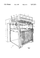
- FIG. 1 is a perspective view of a sheet delivery of a sheet-fed printing machine incorporating therein an air-flow generating device according to the invention
- FIG. 2 is a diagrammatic perspective and partly schematic view of the air-flow generating device and a device for receiving a sheet pile;
- FIG. 3 is an enlarged fragmentary view of the air-flow generating device of FIG. 2 taken in the direction of the arrow III.
- a sheet delivery 1 of a sheet-fed printing machine having a non-illustrated sheet-conveying device preferably constructed as a delivery gripper system for conveying printed sheets coming from a non-illustrated printing unit at high speed.
- Grippers of the delivery gripper system open to release the printed sheets, the velocity of the printed sheets being braked by a suction roller or sheet braking device 2, and the sheets being deposited on a device 3 for receiving a sheet pile to be formed in this manner.
- the device 3 is formed with a stop 4 for respective leading edges of the sheets, stops 5 (FIG.
- an air-flow generating device 7 which serves to effect a targeted or selective sheet deposit or delivery onto the sheet pile.
- a vertical air flow or current emerges from the air-flow generating device 7 and, inter alia, increases the velocity of descent of the respective sheet, thus exerts an influence upon the sheet depositing or delivery behavior.
- FIG. 2 shows a constructional realization or embodiment of the air-flow generating device 7 as an air volume chamber 8 having the shape of a cuboidal or parallelepipedal hollow body with a bottom wall 10 having a basal surface 9, a ceiling or top wall 11, side walls 12, a front end wall 13 and a rear end wall 14.
- the area of the basal surface 9 of the air-volume chamber 8 corresponds approximately to the maximally possible sheet format which can be produced on the sheet-fed printing machine.
- Three partitions 15 extending parallel to the side walls 12 are disposed within the air-volume chamber 8 and divide the inner volume of the air-volume chamber 8 into four, preferably equal, sectional or sub-chambers 16.
- Four air-intake connections or unions 17 are provided in the rear end wall 14, each thereof leading into a respective sectional chamber 16 and being connected to an air-intake control device 19 via a pipe or hose connection 18.
- a main air-intake line 20 supplies the air-intake control device 19.
- the main air-in-take line 20 is connected to a non-illustrated compressed-air source or a compressor.
- FIG. 3 which is a fragmentary view of FIG. 2 in the direction of the arrow III towards the air volume chamber 8, the bottom wall 10 is penetrated by outlet openings 21 which are uniformly distributed over the entire basal surface 9 of the air-volume chamber 8.
- the bottom wall 10 is preferably formed of a ferromagnetic round-hole plate, particularly of the type which meets the requirements of German Industrial Norms (DIN) 24 041.
- Magnetic foils 22 of varying planar form are arranged on the bottom wall 10 so as to adhere magnetically thereto, the magnetic foils 22, in accordance with the shape and position thereof, covering or sealing the respective outlet openings 21 which are involved.
- the magnetic foils 22 form a covering 23 by means of which air-flow intensity and air diffusion of the air flow or current escaping from the perforated bottom wall 10 of the air-volume chamber 8 can be adjusted as desired.
- the sheet delivery according to the invention operates in the following manner:
- the velocity at which the printed sheets are conveyed, approximately horizontally, to the vicinity of the device 3 for receiving the sheet pile is slowed down or braked by the suction roller 2, and the sheets abut the sheet leading-edge stop 4.
- the sheets are guided through the space between the lateral paper stops 5. They are seized simultaneously by the air flow formed by the air-flow generating device 7 and accelerated thereby, as well as delivered precisely aligned and in a guided manner onto the delivery or deposit table 6 already having a sheet pile formed thereon.
- the covering 23 formed of one or more suitably arranged and shaped magnetic foils 22 magnetically adhering to the bottom wall 10 of the air-volume chamber 8, a selected number of the outlet openings 21 are covered or sealed so that not even any partial air flows are able to escape therethrough.
- the sheets to be deposited or delivered are subjected to an air-flow intensity and air diffusion which has been adjusted by the covering 23, these air parameters having thus been adjusted very gradually and selectively over the entire basal surface 9 due to the large number of outlets 21 and the many possible ways of covering them.
- the magnetic foils 22 By appropriately arranging the magnetic foils 22, the printing format, the motif or subject formation, the ink/dampening medium distribution and, if necessary, the resulting waviness of the sheet to be delivered, for example, may be taken into account.
- the pressman may possibly have to alter the covering 23 by, for example, taking into account a changed sheet format and/or a different motif or subject and/or a different type of printing material or paper with respect to the agreed or complete printing job.
- the pressman may prepare in advance or make-ready coverings 23 which he can readily exchange for a previously used covering 23.
- the magnetic foils 22 may also be provided without problem on the bottom wall 10 of the air-volume chamber 8 so that regions thereof overlap.
- the sheet delivery constructed in accordance with the invention may, in a very simple and rapid, finely controllable manner, be adapted to the varying delivery or depositing behavior of different printing products. It is not difficult to achieve a swift and reliable, reproducible sheet deposit or delivery, even at extremely high printing speeds.
- the air-intake control device 19 which, in accordance with another embodiment of the invention, may also be constructed as a control valve.
- the air-intake control device 19 the main air flow supplied by a suitable non-illustrated production device via the main air-intake line 20 is split individually and fed to the individual sectional or sub-chambers 16 via the pipe and hose connections 18, respectively, and via the air-intake connections or unions 17.
- a sectional or sub-chamber 16 with more or less air flow.
- each partition field being provided with an air-intake connection or union 17 so that it is possible to activate respective outlet openings 21 in a very fine screening or scanning grid.
Landscapes
- Engineering & Computer Science (AREA)
- Mechanical Engineering (AREA)
- Delivering By Means Of Belts And Rollers (AREA)
- Pile Receivers (AREA)
- Supply, Installation And Extraction Of Printed Sheets Or Plates (AREA)
Applications Claiming Priority (2)
| Application Number | Priority Date | Filing Date | Title |
|---|---|---|---|
| DE4213020 | 1992-04-21 | ||
| DE4213020A DE4213020B4 (de) | 1992-04-21 | 1992-04-21 | Luftstromerzeugungseinrichtung für einen Bogenausleger einer Bogendruckmaschine |
Publications (1)
| Publication Number | Publication Date |
|---|---|
| US5377971A true US5377971A (en) | 1995-01-03 |
Family
ID=6457107
Family Applications (1)
| Application Number | Title | Priority Date | Filing Date |
|---|---|---|---|
| US08/050,709 Expired - Fee Related US5377971A (en) | 1992-04-21 | 1993-04-21 | Air-flow generating device for a sheet delivery of a sheet-fed printing machine |
Country Status (4)
| Country | Link |
|---|---|
| US (1) | US5377971A (de) |
| JP (1) | JP3302090B2 (de) |
| DE (1) | DE4213020B4 (de) |
| GB (1) | GB2266295B (de) |
Cited By (2)
| Publication number | Priority date | Publication date | Assignee | Title |
|---|---|---|---|---|
| US20090166958A1 (en) * | 2006-03-30 | 2009-07-02 | Mitsubishi Heavy Industries, Ltd. | Sheet-Discharging Apparatus for Sheet-Fed Printing Press |
| US20120291300A1 (en) * | 2011-05-20 | 2012-11-22 | Fih (Hong Kong) Limited | Air drying apparatus |
Families Citing this family (4)
| Publication number | Priority date | Publication date | Assignee | Title |
|---|---|---|---|---|
| DE29517508U1 (de) * | 1995-11-04 | 1996-01-04 | Roland Man Druckmasch | Blaslufteinrichtung für Ausleger einer Bogendruckmaschine |
| DE19631814C1 (de) * | 1996-08-07 | 1998-01-29 | Roland Man Druckmasch | Blaslufteinrichtung für einen Bogenausleger einer Verarbeitungsmaschine |
| JP4059775B2 (ja) * | 2003-01-14 | 2008-03-12 | リョービ株式会社 | 排紙装置の気流吹付け構造および気流吹付け方法 |
| DE102007052382A1 (de) * | 2007-10-31 | 2009-05-07 | Heidelberger Druckmaschinen Ag | Bedieneinrichtung zur Steuerung von Luftdosiervorrichtungen in Druckmaschinen |
Citations (16)
| Publication number | Priority date | Publication date | Assignee | Title |
|---|---|---|---|---|
| DE649326C (de) * | 1936-06-20 | 1937-08-20 | Julius Fischer Fa | Bogenablegevorrichtung |
| US2769495A (en) * | 1953-07-01 | 1956-11-06 | John Waldron Corp | Web cutting and sheet delivery and stacking mechanism |
| GB990470A (en) * | 1961-09-04 | 1965-04-28 | Walker Enfield Ltd | Improvements in or relating to sheet delivery apparatus |
| DE1282556B (de) * | 1966-12-01 | 1968-11-07 | Ungerer Irma | Fuer verschiedene Blechgroessen geeignete Anlage zum selektiven Foerdern und Stapeln von aufeinanderfolgend zugefuehrten Blechtafeln |
| DE1511266A1 (de) * | 1966-07-22 | 1969-07-24 | Paul Lippke | Verfahren und Vorrichtung zum Foerdern und Ablegen bzw. zum Foerdern und Sortieren von Bogen aus Papier,Karton,Metallfolien od.dgl. |
| DE1906090A1 (de) * | 1969-02-07 | 1970-08-20 | Ramisch & Co Maschb Dr | Vorrichtung zum Foerdern und Stapeln von flaechigen Guetern mit empfindlicher Oberflaeche,insbesondere solche aus Kunststoff und anderen empfindlichen Materialien |
| GB1247549A (en) * | 1967-12-27 | 1971-09-22 | Sperry Rand Corp | Document stacking device |
| US3880297A (en) * | 1974-03-13 | 1975-04-29 | Fabricacion De Maquinas | Sheet stacking apparatus |
| US3971554A (en) * | 1975-01-09 | 1976-07-27 | Xerox Corporation | Sheet stacker |
| US4062536A (en) * | 1976-09-16 | 1977-12-13 | Ncr Corporation | Document air valve |
| DE2944227A1 (de) * | 1978-11-08 | 1980-05-22 | Polygraph Leipzig | Einrichtung zum ablegen von bogen an bogenauslegern |
| US4405125A (en) * | 1981-09-14 | 1983-09-20 | Pitney Bowes Inc. | Paper stacking device |
| US4526648A (en) * | 1983-03-02 | 1985-07-02 | Video Design Pty. Ltd. | Airjet label applicator |
| DE3413179A1 (de) * | 1984-04-07 | 1985-10-24 | Miller-Johannisberg Druckmaschinen Gmbh, 6200 Wiesbaden | Steuer- und regelvorrichtung eines bogenauslegers fuer bogenverarbeitende maschinen, insbesondere fuer bogendruckmaschinen |
| US4625956A (en) * | 1984-05-07 | 1986-12-02 | Fa. Georg Spiess Gmbh | Apparatus for forming a stack of sheets |
| DE3920407A1 (de) * | 1988-08-03 | 1990-02-08 | Hilmar Vits | Vorrichtung zum ablegen von bogen an einer stapelstelle |
Family Cites Families (4)
| Publication number | Priority date | Publication date | Assignee | Title |
|---|---|---|---|---|
| DE1252139C2 (de) * | 1965-04-13 | 1968-04-25 | C Mueller Kg | Vorrichtung zum ablegen von Furnierblättern auf einem Stapel |
| DD133654B1 (de) * | 1978-01-18 | 1980-08-06 | Moebius Klaus Dieter | Verfahren und vorrichtung zum beschleunigten ablegen blattfoermiger materialien |
| DD137079A1 (de) * | 1978-01-25 | 1979-08-15 | Hans Zimmermann | Bogenleiteinrichtung in bogenauslegern von druckmaschinen |
| DE4012943A1 (de) * | 1990-04-24 | 1991-10-31 | Hilmar Vits | Verfahren und vorrichtung zum ueberlappen von in einer ebene hintereinander gefoerderten bogen |
-
1992
- 1992-04-21 DE DE4213020A patent/DE4213020B4/de not_active Expired - Fee Related
-
1993
- 1993-04-16 GB GB9307874A patent/GB2266295B/en not_active Expired - Fee Related
- 1993-04-21 JP JP09408993A patent/JP3302090B2/ja not_active Expired - Fee Related
- 1993-04-21 US US08/050,709 patent/US5377971A/en not_active Expired - Fee Related
Patent Citations (18)
| Publication number | Priority date | Publication date | Assignee | Title |
|---|---|---|---|---|
| DE649326C (de) * | 1936-06-20 | 1937-08-20 | Julius Fischer Fa | Bogenablegevorrichtung |
| US2769495A (en) * | 1953-07-01 | 1956-11-06 | John Waldron Corp | Web cutting and sheet delivery and stacking mechanism |
| GB990470A (en) * | 1961-09-04 | 1965-04-28 | Walker Enfield Ltd | Improvements in or relating to sheet delivery apparatus |
| DE1511266A1 (de) * | 1966-07-22 | 1969-07-24 | Paul Lippke | Verfahren und Vorrichtung zum Foerdern und Ablegen bzw. zum Foerdern und Sortieren von Bogen aus Papier,Karton,Metallfolien od.dgl. |
| DE1282556B (de) * | 1966-12-01 | 1968-11-07 | Ungerer Irma | Fuer verschiedene Blechgroessen geeignete Anlage zum selektiven Foerdern und Stapeln von aufeinanderfolgend zugefuehrten Blechtafeln |
| GB1247549A (en) * | 1967-12-27 | 1971-09-22 | Sperry Rand Corp | Document stacking device |
| DE1906090A1 (de) * | 1969-02-07 | 1970-08-20 | Ramisch & Co Maschb Dr | Vorrichtung zum Foerdern und Stapeln von flaechigen Guetern mit empfindlicher Oberflaeche,insbesondere solche aus Kunststoff und anderen empfindlichen Materialien |
| US3880297A (en) * | 1974-03-13 | 1975-04-29 | Fabricacion De Maquinas | Sheet stacking apparatus |
| US3971554A (en) * | 1975-01-09 | 1976-07-27 | Xerox Corporation | Sheet stacker |
| US4062536A (en) * | 1976-09-16 | 1977-12-13 | Ncr Corporation | Document air valve |
| DE2944227A1 (de) * | 1978-11-08 | 1980-05-22 | Polygraph Leipzig | Einrichtung zum ablegen von bogen an bogenauslegern |
| GB2037259A (en) * | 1978-11-08 | 1980-07-09 | Polygraph Leipzig | Apparatus for depositing sheets |
| US4405125A (en) * | 1981-09-14 | 1983-09-20 | Pitney Bowes Inc. | Paper stacking device |
| US4526648A (en) * | 1983-03-02 | 1985-07-02 | Video Design Pty. Ltd. | Airjet label applicator |
| DE3413179A1 (de) * | 1984-04-07 | 1985-10-24 | Miller-Johannisberg Druckmaschinen Gmbh, 6200 Wiesbaden | Steuer- und regelvorrichtung eines bogenauslegers fuer bogenverarbeitende maschinen, insbesondere fuer bogendruckmaschinen |
| US4625956A (en) * | 1984-05-07 | 1986-12-02 | Fa. Georg Spiess Gmbh | Apparatus for forming a stack of sheets |
| DE3920407A1 (de) * | 1988-08-03 | 1990-02-08 | Hilmar Vits | Vorrichtung zum ablegen von bogen an einer stapelstelle |
| US5060928A (en) * | 1988-08-03 | 1991-10-29 | Hilmar Vits | Apparatus for the depositing of sheets at a stacking location |
Cited By (2)
| Publication number | Priority date | Publication date | Assignee | Title |
|---|---|---|---|---|
| US20090166958A1 (en) * | 2006-03-30 | 2009-07-02 | Mitsubishi Heavy Industries, Ltd. | Sheet-Discharging Apparatus for Sheet-Fed Printing Press |
| US20120291300A1 (en) * | 2011-05-20 | 2012-11-22 | Fih (Hong Kong) Limited | Air drying apparatus |
Also Published As
| Publication number | Publication date |
|---|---|
| GB9307874D0 (en) | 1993-06-02 |
| DE4213020A1 (de) | 1993-10-28 |
| GB2266295A (en) | 1993-10-27 |
| DE4213020B4 (de) | 2004-09-16 |
| GB2266295B (en) | 1995-08-09 |
| JPH0616305A (ja) | 1994-01-25 |
| JP3302090B2 (ja) | 2002-07-15 |
Similar Documents
| Publication | Publication Date | Title |
|---|---|---|
| JP3655670B2 (ja) | 紙葉状材料を非接触に案内する装置 | |
| US5411251A (en) | Sheet delivery of a printing machine with a floating conveyor | |
| JPH0825266B2 (ja) | 片面又は両面印刷された枚葉紙の案内装置 | |
| US5092578A (en) | Sheet feeder in a sheet-processing machine | |
| CN102171121B (zh) | 堆纸器中的有节奏的吹风 | |
| JP3325627B2 (ja) | 印刷された枚葉紙をパイル上に排紙するための装置 | |
| US7513499B2 (en) | Sheet brake using a partitioned blower nozzle array | |
| US6889609B2 (en) | Method and device for generating an air stream in a duplicating machine | |
| US5377971A (en) | Air-flow generating device for a sheet delivery of a sheet-fed printing machine | |
| US9278821B2 (en) | Device and method for suctioning a sheet from a sheet stack and sheet-fed rotary printing machine and punch having the device | |
| US6527268B2 (en) | Method and device for contact-free guidance of sheets | |
| US5671918A (en) | Sheet delivery for a sheet-processing machine | |
| JP3703803B2 (ja) | 加工機械内でウェブ材料または枚葉紙材料を浮遊させながらガイドするための装置 | |
| US6378425B1 (en) | Sheet-guiding device for printing presses | |
| US6702283B2 (en) | Device for decurling flat printing materials | |
| US7219889B2 (en) | Sheet-processing machine with a pneumatic sheet-guiding device | |
| JP2009543748A (ja) | シート供給印刷機におけるシートの供給を実現又は制御するために周囲圧力と異なる圧力を生成して印刷機に供給する方法及び手段 | |
| US6726203B1 (en) | Sheet guide arrangement in a printing machine | |
| JP2795842B2 (ja) | 加工機械に設けられた排紙装置のためのブローエア装置 | |
| JP4410966B2 (ja) | 枚葉紙の無接触保持のための装置 | |
| US6910416B2 (en) | Suction guidance device for a single-drum turner | |
| JP2003118072A (ja) | 枚葉印刷機のシートガイド装置およびその制御方法 | |
| JP3703804B2 (ja) | 加工機械内でウェブ材料または枚葉紙材料を浮遊させながらガイドするための装置 | |
| EP0765830A1 (de) | Bogenablagesystem | |
| JP2001096723A (ja) | 印刷機の排紙部プリセット方法及びその装置 |
Legal Events
| Date | Code | Title | Description |
|---|---|---|---|
| AS | Assignment |
Owner name: HEIDELBERGER DRUCKMASCHINEN AG Free format text: ASSIGNMENT OF ASSIGNORS INTEREST;ASSIGNOR:GANTER, UDO;REEL/FRAME:007153/0544 Effective date: 19940507 |
|
| FEPP | Fee payment procedure |
Free format text: PAYOR NUMBER ASSIGNED (ORIGINAL EVENT CODE: ASPN); ENTITY STATUS OF PATENT OWNER: LARGE ENTITY |
|
| FPAY | Fee payment |
Year of fee payment: 4 |
|
| FPAY | Fee payment |
Year of fee payment: 8 |
|
| REMI | Maintenance fee reminder mailed | ||
| LAPS | Lapse for failure to pay maintenance fees | ||
| LAPS | Lapse for failure to pay maintenance fees |
Free format text: PATENT EXPIRED FOR FAILURE TO PAY MAINTENANCE FEES (ORIGINAL EVENT CODE: EXP.); ENTITY STATUS OF PATENT OWNER: LARGE ENTITY |
|
| STCH | Information on status: patent discontinuation |
Free format text: PATENT EXPIRED DUE TO NONPAYMENT OF MAINTENANCE FEES UNDER 37 CFR 1.362 |
|
| FP | Lapsed due to failure to pay maintenance fee |
Effective date: 20070103 |