US5102229A - Agitator - Google Patents
Agitator Download PDFInfo
- Publication number
- US5102229A US5102229A US07/679,854 US67985491A US5102229A US 5102229 A US5102229 A US 5102229A US 67985491 A US67985491 A US 67985491A US 5102229 A US5102229 A US 5102229A
- Authority
- US
- United States
- Prior art keywords
- agitator
- blade
- vessel
- agitation
- axis
- Prior art date
- Legal status (The legal status is an assumption and is not a legal conclusion. Google has not performed a legal analysis and makes no representation as to the accuracy of the status listed.)
- Expired - Lifetime
Links
Images


Classifications
-
- B—PERFORMING OPERATIONS; TRANSPORTING
- B01—PHYSICAL OR CHEMICAL PROCESSES OR APPARATUS IN GENERAL
- B01F—MIXING, e.g. DISSOLVING, EMULSIFYING OR DISPERSING
- B01F27/00—Mixers with rotary stirring devices in fixed receptacles; Kneaders
- B01F27/80—Mixers with rotary stirring devices in fixed receptacles; Kneaders with stirrers rotating about a substantially vertical axis
- B01F27/84—Mixers with rotary stirring devices in fixed receptacles; Kneaders with stirrers rotating about a substantially vertical axis with two or more stirrers rotating at different speeds or in opposite directions about the same axis
-
- B—PERFORMING OPERATIONS; TRANSPORTING
- B01—PHYSICAL OR CHEMICAL PROCESSES OR APPARATUS IN GENERAL
- B01F—MIXING, e.g. DISSOLVING, EMULSIFYING OR DISPERSING
- B01F27/00—Mixers with rotary stirring devices in fixed receptacles; Kneaders
- B01F27/60—Mixers with rotary stirring devices in fixed receptacles; Kneaders with stirrers rotating about a horizontal or inclined axis
- B01F27/70—Mixers with rotary stirring devices in fixed receptacles; Kneaders with stirrers rotating about a horizontal or inclined axis with paddles, blades or arms
Definitions
- the present invention relates to an agitator usable in batch processing of various viscous fluids performed in chemical, pharmaceutical and food industries to manufacture products in small quantities and in a variety of types.
- the agitator is also usable in processes in which, during the operation of the apparatus, reaction, dissolving or the like causes the liquid viscosity to change within a wide range, and the flow in the vessel to change from turbulent flow to laminar flow.
- the liquid flow characteristics within an agitator vessel greatly vary between a low-viscosity region (turbulent flow region) and a high-viscosity region (laminar flow region). Also, the manner of flowing and mixing varies between these regions.
- baffle plate in the vessel is believed to be essential in general.
- a baffle plate leads to the problem of a portion of the liquid remaining on and adhering to the back surface of the baffle plate.
- a baffle plate In the case of a low-concentration slurry liquid, a baffle plate is very effective to achieve uniform dispersion of solid particles. However, when the slurry concentration increases, the baffle plate acts to help solid particles to remain, deposit and solidify on the wall portion of the vessel interior.
- an agitator vessel 1 has a helical ribbon blade 12 disposed therein, which is rotatable along the inner surface of the side wall of the vessel 1.
- paddle blades 13 are radially provided on an agitation axis 2 at the center of the interior of the agitator vessel 1, which are rotatable in the opposite direction to that of the helical ribbon blade 12.
- FIG. 7 Japanese Patent Examined Publication No. 1-37173.
- a flat-plate-shaped blade 6 is provided on a lower portion of an agitation axis 2 at the center of the interior of an agitator vessel 1, which is disposed along the inner surface of the bottom wall of the agitator vessel 1.
- a grating-shaped blade 7 continuing from the flat-plate-shaped blade 6 is provided on an upper portion of the agitation axis 2.
- a plurality of baffle plates 14 are provided in a spaced relationship with each other on the inner surface of the side wall of the vessel 1, each baffle plate 14 extending axially from a lower position to an upper position of that inner surface.
- the agitator blade having the first construction where the helical ribbon blade 12 and the paddle blades 13 are used as the agitator blade the agitator blade having a complicated structure makes operations such as charging, discharging and transferring difficult, thereby involving a risk of trouble
- Another disadvantage is that since no effective blade is provided in the bottom portion of the agitator vessel interior, the liquid flow in the bottom portion is extremely inactive. Further, an agitating operation cannot be started by charging a small amount of liquid. Still further, since the paddle blades 13 disposed radially inward of the helical ribbon blade 12 are provided in a plurality of stages, the circulating flow generated by each paddle blade 13 in one of the stages collides with another circulating flow at the intermediate surface between these stages, thereby forming a remaining portion. Such a remaining portion acts as a boundary which deteriorates the degree of inter-stage mixing. Further, when the liquid level changes, this causes a change in the relationship between the position of the liquid surface and the position at which the blades are mounted.
- the agitator having the second construction where the agitator blade consisting of the flat-plate-shaped blade 6 and the grating-shaped blade 7 continuous therewith is used together with the baffle plates 14, does not entail the disadvantages of the first agitator, and the apparatus is advantageous in that the flow generating characteristics of the agitator blade enable a reduction in the mixing period, and that the applicable viscosity range is wide.
- the provision of the baffle plates 14 inevitably leads to problems such as those described above, that is, formation of a remaining portion on the back surface of the baffle plates when the liquid viscosity increases, occurrence of flow failure in a high viscosity region, and remaining, deposition and solidification of solid particles on the wall portion of the vessel interior when the slurry concentration increases.
- the present invention has been accomplished to overcome the problems of an agitator of the second type, and aims to make an agitator operable with effective liquid mixing characteristics even at high viscosities and high concentrations to thereby achieve a drastic expansion of the range within which a single apparatus is applicable, while preventing remaining, deposition and solidification of solid particles on the side wall portion of the vessel interior at high concentrations.
- an agitator comprising: an agitator vessel; first and second agitation axes rotatably provided at the center of the agitator vessel; an agitator blade mounted on the first agitation axis, the agitator blade consisting of a flat-plate-shaped blade disposed along the inner surface of the bottom wall of the agitator vessel and a grating-shaped blade disposed above the flat-plate-shaped blade continuously therewith; at least one baffle plate mounted on the second agitation axis, the baffle plates extending outside the range within which the agitator blade rotates, and vertically along the inner surface of the side wall of the agitator vessel; and drive equipment for rotating the first and second agitation axes independently from each other.
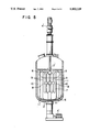
- FIG. 1 is a front sectional view of an embodiment of the present invention
- FIGS. 2A, 2B and 2C are views schematically showing three different examples of baffle plates for the apparatus according to the present invention.
- FIGS. 3A, 3B, 3C and 3D are views showing four different examples of the sectional configuration of the baffle plates
- FIG. 4 is a graph showing the example of a relationship between the liquid viscosity and the ratio representing the rotational speeds of the agitator blade and the baffle plates according to the present invention
- FIG. 5 is a front sectional view of another embodiment of the present invention.
- FIG. 6 is a front sectional view of a conventional agitator
- FIG. 7 is a front sectional view of another conventional agitator.
- FIG. 8 is a sectional view of an additional embodiment of the invention.
- an agitator according to an embodiment of the present invention has a cylindrical agitator vessel 1. Disposed at the center of the interior of the agitator vessel 1 are an inner agitation axis 2 extending to a position in the vicinity of the bottom wall of the vessel 1 and an outer agitation axis 3 extending to a position above the liquid surface level, the inner and outer axes 2 and 3 being fitted together while rotatable relative to each other.
- These agitation axes 2 and 3 can be stopped and rotated independently from each other by drive devices 4 and 5, respectively, provided above the upper wall of the agitator vessel 1.
- the direction and the speed of the respective rotations of the agitation axes 2 and 3 can be controlled independently from each other.
- the agitator includes a flat-plate-shaped blade 6 disposed along the inner surface of the bottom wall of the agitator vessel 1.
- the blade 6 is mounted on a lower portion of the inner agitation axis 2, and is in sliding contact with the inner surface of the bottom wall of the vessel 1.
- the flat-plate-shaped blade 6 has both the characteristics (the discharging characteristics) of a conventionally known paddle blade and the characteristics (the shearing and scraping characteristics) of a conventionally known horse-shoe-type or anchor-type blade. Specifically, the blade 6 has the characteristics of a paddle blade whereby liquid is discharged in the radial direction of the vessel, and the characteristics of a horse-shoe-type or anchor-type blade whereby the substances adhering to the wall surface are scraped off, scattered and floated.
- a grating-shaped blade 7 continues from the flat-plate-shaped blade 6, and is mounted, as the blade 6, on the inner agitation axis 2.
- the grating-shaped blade 7 consists of a plurality of flat-bar-shaped horizontal ribs 8 extending radially of the vessel 1 and a plurality of flat-bar-shaped vertical strips 9 extending vertically, that is, perpendicularly to the horizontal ribs 8.
- the grating-shaped blade 7 has certain characteristics with which, during the rotation of the blade 7, the respective end portions of the components of the blade 7 shear the liquid and divide it into small parts, and the small parts of the liquid divided are mixed together by the action of minute swirls generated behind those components.
- the flat-plate-shaped blade 6 and the grating-shaped blade 7 are integrally formed to constitute an agitator blade.
- the blades 6 and 7 will therefore be referred to generically as "the agitator blade” unless otherwise specified.
- each of the above-described vertical strips 9 extends across all of the horizontal ribs 8, this is a mere example. Alternatively, the vertical strips 9 may be combined with different ones of the horizontal ribs 8.
- the horizontal ribs 8 are provided to reinforce the grating-shaped blade 7. Needless to say, the number of the horizontal ribs 8, which is determined by the dimensions of the blade 7, is not limited to that of the illustrated embodiment, and may be other than two.
- the apparatus further includes a plurality of baffle plates 10 detachably mounted on the distal ends of linkage ribs 11 provided on the outer agitation axis 3.
- the baffle plates 10 vertically extend outside the range of rotation of the agitator blade 6, 7, and are in sliding contact with the inner surface of the side wall of the agitator vessel 1. Examples of baffle plates are shown in FIGS. 2A to 2C.
- FIG. 2A illustrates a baffle plate 10 extending vertically straight along the side wall of the agitator vessel 1.
- the baffle plate 10 may have various sectional configurations.
- the baffle plate 10 is a flat plate having a rectangular section, as shown in FIG. 3A.
- the baffle plate 10 may, however, have a triangular section, as shown in FIG. 3B, a semi-circular section, as shown in FIG. 3C, or a T-shaped section, as shown in FIG. 3D.
- FIGS. 2B and 2C illustrates baffle plates having certain counter angles.
- FIG. 2B illustrates a baffle plate 10' having a counter angle determined by a pitch (0.5) relative to the vertical length of the agitator blade.
- FIG. 2C illustrates a baffle plate 10" having a counter angle determined by a different pitch (1.0) relative to the vertical length of the agitator blade.
- the pitch determining the counter angle should preferably be a value which is not greater than 1.5 relative to said length.
- the baffle plates 10, 10' or 10" have the characteristics of: causing the flow radially discharged by the rotation of the flat-plate-shaped blade 6 to ascend along the inner surface of the side wall of the vessel, so as to form circulating flow in the vessel; causing the substances adhering to the wall surface to be scraped off, scattered and floated; and pushing the liquid when the viscosity increases so as to keep it in motion and reduce the risk of a drop in the flow speed at the side wall portion of the vessel interior.
- baffle plates 10, 10' or 10" are used in the apparatus, the number of baffle plates may be suitably increased or decreased (even to one) in accordance with the condition of use.
- FIG. 5 shows another embodiment of the present invention.
- the embodiment shown in FIG. 5 is distinguished from the first embodiment shown in FIG. 1 in which the agitator axis has a double axis structure consisting of the inner agitation axis 2 and the outer agitation axis 3.
- the second embodiment is distinguished by the arrangements in which an agitation axis 2' for the agitator blade which corresponds to the inner agitation axis 2 is driven by a drive device 4' provided above the upper wall of the agitator vessel 1, and an agitation axis 3' for the baffle plates which corresponds to the outer agitation axis 3 is driven by a driving device 5' provided at the bottom portion of the agitator vessel 1.
- the other arrangements of the second embodiment are the same as those shown in FIG. 1, and detailed descriptions of these arrangements will be omitted.
- the embodiment shown in FIG. 1 may be modified so that the agitation axes 2 and 3, forming a double axis structure, are driven from below by the drive devices 4 and 5 provided on the bottom portion of the agitator vessel 1.
- the embodiment shown in FIG. 5 may be modified so that the drive device 4' for the agitator blade agitation axis 3' is provided at the upper portion of the vessel 1, while the drive device 5' for the ais 2' is provided above the lower wall of the vessel 1.
- the agitation axis 2 or 2' on which the agitator blade 6, 7 is mounted, and the agitation axis 3 or 3' on which the baffle plates 10, 10' or 10" are mounted are driven by an external drive system, i.e., the drive device 4 or 4' and the drive device 5 or 5', respectively, at different speeds of rotation. Also, the direction of the rotation of these axes are suitably set in accordance with the liquid to be processed and the purpose of the operation.
- the ratio between the respective rotational speeds of the agitation axis 2 or 2' and the agitation axis 3 or 3' is changed by appropriately setting the ratio in accordance with various characteristics of the liquid.
- the agitator blade 6, 7 is rotated by the rotation of the agitation axis 2 or 2' and the baffle plates 10, 10' and 10" are rotated by the rotation of the agitation axis 3 or 3', the flow described below is formed in the agitator vessel 1.
- FIG. 4 is a graph in which the abscissa represents the viscosity (poise) of the liquid agitated, while the ordinate represents the ratio (N2/N1) between the absolute value N1 of the number of revolutions per unit time of the agitator blade and the absolute value N2 of that of the baffle plates.
- the graph shows the example of a relationship between the viscosity and the rotational speeds of the agitator blade and the baffle plates.
- the ratio between the numbers of revolutions of the agitator blade 6, 7 and the baffle plates 10, 10' or 10" is varied in accordance with the properties of the material (liquid) being agitated, the ratio is generally changed in accordance with the viscosity in such a manner that, in a low-viscosity region, the agitator blade and the baffle plates are rotated at a great ratio. With such rotation, a great circulating flow is formed in the agitator vessel 1. Specifically, the liquid is radially discharged by the flat-plate-shaped blade 6 at the lower portion of the agitator blade while the liquid is being prevented from adhering to the inner surface of the lower wall portion of the vessel 1.
- the flow of the discharged liquid is interfered by the baffle plates 10, 10' or 10" in such a manner as to be restrained from circular motion and to ascend along the inner surface of the side wall of the vessel toward the upper portion of the vessel interior. Then, the flow moves in the upper portion from a position close to the side wall to a central position, descends along the agitation axis 2 or 2', and returns to the position of the flat-plate-shaped blade 6.
- the horizontal ribs 8 and the vertical strips 9 of the grating-shaped blade 7 at the upper portion of the agitator blade acts to normally shear a part of the circulating flow which descends along the agitation axis 2 or 2'.
- the liquid is divided into small parts with small power consumption.
- the small parts of the liquid are mixed together by the action of minute swirls generated behind the horizontal ribs 8 and the vertical strips 9.
- the mixing operation is completed within a short period.
- the agitator blade 6, 7 and the baffle plates 10, 10' or 10" are rotated at a relatively small ratio between the numbers of revolutions. With such rotation, the baffle plates 10, 10' or 10" cause the substances adhering to the wall surface to be scraped off, scattered and floated, and also act to reduce the risk of a drop in the liquid flow speed at the side wall portion of the vessel interior when the viscosity increases.
- the rotating baffle plates 10, 10' or 10" are free from any remaining or motionless portion formed on the back surface thereof . Therefore, it is possible to assure that the above-described formation of circulating flow, the dividing of the liquid into small parts and the mixing of the parts, which are all necessary to uniform mixing, are sufficiently performed, while the scraping off of the substances from the wall surface greatly reduces the risk of substances remaining on and adhering to the side wall of the vessel. Furthermore, in the case of a liquid such as a high concentration slurry, the rotating baffle plates 10, 10' or 10" enable the substances deposited on the wall surface to be scraped off before they coagulate and solidify, thus enabling them to be replaced.
- the agitator blade and the baffle plates which are rotated with a difference in rotational speed enables circulating flow to be formed in the agitation vessel.
- the grating-shaped blade at the upper portion of the agitator blade shears that part of the circulating flow descending along the inner agitation axis, thereby dividing the liquid into small parts.
- the small parts of the liquid are efficiently mixed together by the action of minute swirls generated behind the components of the grating-shaped blade.
- the baffle plates act to prevent any portion of the substances being processed from remaining, depositing, solidifying, and adhering (and additionally fusing when the slurry is heated) on the side wall portion of the vessel interior, and to cause any such deposit to be scattered and floated. This action is performed without any of the substances remaining on and adhering to the back surface of the baffle plates.
- the dissolving of the undissolved substances is promoted, and the risk of a drop in the liquid flow speed at the side wall portion of the vessel interior is reduced, thereby assuring the above-described liquid mixing characteristics.
- baffle plates having an angle of attack with respect to the direction of flow, it is possible, when the viscosity is high, to increase the ascending part of circulating flow along the inner surface of the side wall of the vessel.
Applications Claiming Priority (2)
| Application Number | Priority Date | Filing Date | Title |
|---|---|---|---|
| JP15693590 | 1990-06-15 | ||
| JP2-156935 | 1990-06-15 |
Publications (1)
| Publication Number | Publication Date |
|---|---|
| US5102229A true US5102229A (en) | 1992-04-07 |
Family
ID=15638567
Family Applications (1)
| Application Number | Title | Priority Date | Filing Date |
|---|---|---|---|
| US07/679,854 Expired - Lifetime US5102229A (en) | 1990-06-15 | 1991-04-03 | Agitator |
Country Status (8)
| Country | Link |
|---|---|
| US (1) | US5102229A (ko) |
| EP (1) | EP0461746B1 (ko) |
| KR (1) | KR0173472B1 (ko) |
| CN (1) | CN1027868C (ko) |
| AT (1) | ATE117913T1 (ko) |
| AU (1) | AU634044B2 (ko) |
| CA (1) | CA2040009C (ko) |
| DE (1) | DE69107124T2 (ko) |
Cited By (28)
| Publication number | Priority date | Publication date | Assignee | Title |
|---|---|---|---|---|
| US5518312A (en) * | 1993-12-27 | 1996-05-21 | Kajima Corporation | Mixing device and method |
| US5611619A (en) * | 1996-06-27 | 1997-03-18 | Li Yuan Machine Industrial Co., Ltd. | Mixing machine |
| AT404333B (de) * | 1996-12-05 | 1998-10-27 | Pft Systems Vertriebs Gmbh | Vorrichtung zur kontinuierlichen herstellung eines pumpfähigen baumaterials |
| US6012837A (en) * | 1999-01-13 | 2000-01-11 | Thuma; Michael C. | Integrated dual mixing action stirring blender |
| US6012447A (en) * | 1998-07-29 | 2000-01-11 | Stimsonite Corporation | Heated mixing kettle with dual acting agitators |
| US6390664B1 (en) * | 1999-10-21 | 2002-05-21 | Harald Kniele | Compulsory mixer used, in particular, as a cement mixer |
| US20040233780A1 (en) * | 2002-10-25 | 2004-11-25 | De Oliveira Picho Helton Mendes | Disposal for agitator tank |
| US20060163260A1 (en) * | 2003-01-21 | 2006-07-27 | Remy Schmidt | Baffle fixed at a separation from the internal wall of an enamelled container by means of a local connection |
| US7351385B1 (en) * | 2003-12-17 | 2008-04-01 | Clearline Systems, Inc. | System for enabling landfill disposal of kitchen waste oil/grease |
| US20080101156A1 (en) * | 2004-09-21 | 2008-05-01 | Shi Mechanical & Equipment Inc. | Stirring Apparatus |
| US20080148949A1 (en) * | 2006-12-21 | 2008-06-26 | David Stephen Wolfe | Blending jar apparatus structured according to the geometric relationship known as Phi |
| US20080298170A1 (en) * | 2007-05-29 | 2008-12-04 | Daryoosh Beigzadeh | Stirrer and apparatus for small volume mixing |
| US20100177593A1 (en) * | 2007-05-30 | 2010-07-15 | Shi Mechanical & Equipment Inc. | Stirring Apparatus |
| US20100214868A1 (en) * | 2006-10-04 | 2010-08-26 | Shi Mechanical & Equipment Inc. | Agitator and Agitation Method |
| US20110247402A1 (en) * | 2005-10-07 | 2011-10-13 | Brabender Gmbh & Co. Kg | Method for rapid testing of the quality of cereals, grits and flours by measuring the aggregation of gluten |
| CN106362667A (zh) * | 2016-11-19 | 2017-02-01 | 张奇 | 二级搅拌自清洗式反应釜结构 |
| CN106378079A (zh) * | 2016-11-19 | 2017-02-08 | 张奇 | 一种高效率自清洗式反应釜结构 |
| CN106378071A (zh) * | 2016-11-19 | 2017-02-08 | 张奇 | 高效自清洗搅拌装置 |
| CN106492726A (zh) * | 2016-11-19 | 2017-03-15 | 张奇 | 带有多重搅拌的自清洗式反应釜结构 |
| CN106669490A (zh) * | 2017-02-24 | 2017-05-17 | 鞍山兴德材料科技股份有限公司 | 一种固液打浆器 |
| US9907319B2 (en) | 2015-03-13 | 2018-03-06 | Steak 'n Shake Enterprises, Inc. | Dual-axis rotational mixer for food products |
| US10076124B2 (en) | 2015-03-13 | 2018-09-18 | Steak 'n Shake Enterprises, Inc. | Rapid-agitation mixer for food products |
| US10478791B2 (en) | 2015-07-01 | 2019-11-19 | Sumitomo Heavy Industries Process Equipment Co., Ltd. | Stirring device |
| CN111107917A (zh) * | 2017-09-21 | 2020-05-05 | 惠斯勒科技公司 | 用于树脂提取的设备和方法 |
| CN111165117A (zh) * | 2020-03-15 | 2020-05-19 | 邵敏敏 | 一种小麦种植药剂拌种装置 |
| US20210339210A1 (en) * | 2020-04-29 | 2021-11-04 | Sk Innovation Co., Ltd. | Ultra-dispersion mixer |
| CN115232936A (zh) * | 2021-02-10 | 2022-10-25 | 本田技研工业株式会社 | 喷丸硬化装置 |
| CN117160291A (zh) * | 2023-11-02 | 2023-12-05 | 维达纸业(中国)有限公司 | 一种搅拌设备的混合装置 |
Families Citing this family (20)
| Publication number | Priority date | Publication date | Assignee | Title |
|---|---|---|---|---|
| DE4216252C2 (de) * | 1992-05-16 | 1994-05-26 | Albrecht Konietzko | Anordnung mit einem Rührwerk zur Mischung von pharmazeutischen und/oder kosmetischen Salben, Pasten, Cremes, Geleen oder Emulsionen |
| CN1094780C (zh) * | 2000-02-22 | 2002-11-27 | 中国石油化工集团公司 | 用于多层搅拌桨的自旋导流装置 |
| JP2003033635A (ja) * | 2001-05-17 | 2003-02-04 | Shinko Pantec Co Ltd | 攪拌翼およびこれを用いた攪拌装置ならびに攪拌方法 |
| KR101126518B1 (ko) * | 2004-07-05 | 2012-06-12 | 조용래 | 배합물의 분산장치 및 분산방법 |
| KR100738643B1 (ko) * | 2006-08-08 | 2007-07-11 | 주식회사 엘지생활건강 | 교반 장치 |
| KR100738642B1 (ko) * | 2006-08-08 | 2007-07-11 | 주식회사 엘지생활건강 | 교반 장치 |
| DE102007018130B4 (de) * | 2007-04-16 | 2010-06-17 | Fischer & Krecke Gmbh | Farbbehälter |
| CN101708556B (zh) * | 2009-10-23 | 2011-01-26 | 南京金视显科技有限公司 | 还原法制备银粉的分散方法和装置 |
| CN101912743B (zh) * | 2010-08-10 | 2012-04-18 | 杭州三拓印染设备技术开发有限公司 | 打浆机叶片 |
| EP2653216A1 (en) * | 2012-04-16 | 2013-10-23 | Strategisch Initiatief Materialen vzw | Baffle system and magnetic mixing system comprising such baffle system |
| CN103043233A (zh) * | 2013-01-10 | 2013-04-17 | 贵州大学 | 用于油辣椒的灌装装置 |
| DE102013018725A1 (de) | 2013-11-08 | 2015-05-13 | Wusoa Gmbh | Bionisches Rührwerk |
| CN105221444A (zh) * | 2015-10-31 | 2016-01-06 | 重庆渝牛食品有限公司 | 用于糖浆输送的泵 |
| CN105352311B (zh) * | 2015-11-27 | 2017-10-27 | 成都九十度工业产品设计有限公司 | 食品物料干燥搅拌装置 |
| CN107242301A (zh) * | 2017-07-26 | 2017-10-13 | 云南省石屏县花腰豆制品工贸有限公司 | 石屏豆腐点卤设备 |
| CN107551866B (zh) * | 2017-08-30 | 2023-08-04 | 山东省淡水渔业研究院(山东省淡水渔业监测中心) | 佐剂与抗原的快速混合装置 |
| CN108007805B (zh) * | 2017-11-30 | 2019-12-06 | 青岛科技大学 | 一种全自动型可移动的涂层性能监测装置 |
| CN108479682A (zh) * | 2018-06-08 | 2018-09-04 | 杭州原正化学工程技术装备有限公司 | 一种适合超高粘聚合体系的搅拌器 |
| CN109261101A (zh) * | 2018-09-12 | 2019-01-25 | 上海化工研究院有限公司 | 一种强化烯烃聚合的搅拌结构及强化烯烃聚合的方法 |
| DE102021005219A1 (de) | 2021-10-19 | 2023-04-20 | Marcel Janssen | Antriebseinheit für Rührwerke mit gegenläufigen Rührwerkzeugen |
Citations (4)
| Publication number | Priority date | Publication date | Assignee | Title |
|---|---|---|---|---|
| US877468A (en) * | 1907-02-11 | 1908-01-21 | Triumph Mfg Company | Egg and sponge beater. |
| US2876082A (en) * | 1954-07-12 | 1959-03-03 | Union Stock Yard & Transit Co Chicago | Apparatus for making soap |
| US3578876A (en) * | 1969-06-06 | 1971-05-18 | King Of Prussia Research & Dev | Mixer |
| US4403868A (en) * | 1980-07-21 | 1983-09-13 | Dieter Kupka | Agitator with two sets of blades each driven in an opposite direction about a common axis |
Family Cites Families (1)
| Publication number | Priority date | Publication date | Assignee | Title |
|---|---|---|---|---|
| GB2158727B (en) * | 1984-05-03 | 1987-08-05 | Chem Plant Stainless Ltd | Mixing apparatus |
-
1991
- 1991-04-03 US US07/679,854 patent/US5102229A/en not_active Expired - Lifetime
- 1991-04-04 DE DE69107124T patent/DE69107124T2/de not_active Expired - Lifetime
- 1991-04-04 AU AU74090/91A patent/AU634044B2/en not_active Expired
- 1991-04-04 EP EP91302978A patent/EP0461746B1/en not_active Expired - Lifetime
- 1991-04-04 AT AT91302978T patent/ATE117913T1/de not_active IP Right Cessation
- 1991-04-08 CA CA002040009A patent/CA2040009C/en not_active Expired - Lifetime
- 1991-04-09 KR KR1019910005666A patent/KR0173472B1/ko not_active IP Right Cessation
- 1991-04-10 CN CN91102278A patent/CN1027868C/zh not_active Expired - Lifetime
Patent Citations (4)
| Publication number | Priority date | Publication date | Assignee | Title |
|---|---|---|---|---|
| US877468A (en) * | 1907-02-11 | 1908-01-21 | Triumph Mfg Company | Egg and sponge beater. |
| US2876082A (en) * | 1954-07-12 | 1959-03-03 | Union Stock Yard & Transit Co Chicago | Apparatus for making soap |
| US3578876A (en) * | 1969-06-06 | 1971-05-18 | King Of Prussia Research & Dev | Mixer |
| US4403868A (en) * | 1980-07-21 | 1983-09-13 | Dieter Kupka | Agitator with two sets of blades each driven in an opposite direction about a common axis |
Cited By (34)
| Publication number | Priority date | Publication date | Assignee | Title |
|---|---|---|---|---|
| US5518312A (en) * | 1993-12-27 | 1996-05-21 | Kajima Corporation | Mixing device and method |
| US5611619A (en) * | 1996-06-27 | 1997-03-18 | Li Yuan Machine Industrial Co., Ltd. | Mixing machine |
| AT404333B (de) * | 1996-12-05 | 1998-10-27 | Pft Systems Vertriebs Gmbh | Vorrichtung zur kontinuierlichen herstellung eines pumpfähigen baumaterials |
| US6012447A (en) * | 1998-07-29 | 2000-01-11 | Stimsonite Corporation | Heated mixing kettle with dual acting agitators |
| US6012837A (en) * | 1999-01-13 | 2000-01-11 | Thuma; Michael C. | Integrated dual mixing action stirring blender |
| US6390664B1 (en) * | 1999-10-21 | 2002-05-21 | Harald Kniele | Compulsory mixer used, in particular, as a cement mixer |
| US20040233780A1 (en) * | 2002-10-25 | 2004-11-25 | De Oliveira Picho Helton Mendes | Disposal for agitator tank |
| US7607821B2 (en) * | 2003-01-21 | 2009-10-27 | De Dietrich | Baffle secured at a distance from the inner wall of a glass-lined container by means of a local connection |
| US20060163260A1 (en) * | 2003-01-21 | 2006-07-27 | Remy Schmidt | Baffle fixed at a separation from the internal wall of an enamelled container by means of a local connection |
| US7351385B1 (en) * | 2003-12-17 | 2008-04-01 | Clearline Systems, Inc. | System for enabling landfill disposal of kitchen waste oil/grease |
| US20080101156A1 (en) * | 2004-09-21 | 2008-05-01 | Shi Mechanical & Equipment Inc. | Stirring Apparatus |
| US7934867B2 (en) | 2004-09-21 | 2011-05-03 | Sumitomo Heavy Industries Process Equipment Co., Ltd. | Stirring apparatus |
| US20110247402A1 (en) * | 2005-10-07 | 2011-10-13 | Brabender Gmbh & Co. Kg | Method for rapid testing of the quality of cereals, grits and flours by measuring the aggregation of gluten |
| US8555707B2 (en) * | 2005-10-07 | 2013-10-15 | Brabender Gmbh & Co. Kg | Device for rapid testing of the quality of cereals, grits and flours by measuring the aggregation of gluten |
| US20100214868A1 (en) * | 2006-10-04 | 2010-08-26 | Shi Mechanical & Equipment Inc. | Agitator and Agitation Method |
| US20080148949A1 (en) * | 2006-12-21 | 2008-06-26 | David Stephen Wolfe | Blending jar apparatus structured according to the geometric relationship known as Phi |
| US20080298170A1 (en) * | 2007-05-29 | 2008-12-04 | Daryoosh Beigzadeh | Stirrer and apparatus for small volume mixing |
| US8434931B2 (en) | 2007-05-29 | 2013-05-07 | Dow Global Technologies Llc | Stirrer and apparatus for small volume mixing |
| US20100177593A1 (en) * | 2007-05-30 | 2010-07-15 | Shi Mechanical & Equipment Inc. | Stirring Apparatus |
| US10076124B2 (en) | 2015-03-13 | 2018-09-18 | Steak 'n Shake Enterprises, Inc. | Rapid-agitation mixer for food products |
| US9907319B2 (en) | 2015-03-13 | 2018-03-06 | Steak 'n Shake Enterprises, Inc. | Dual-axis rotational mixer for food products |
| US10478791B2 (en) | 2015-07-01 | 2019-11-19 | Sumitomo Heavy Industries Process Equipment Co., Ltd. | Stirring device |
| CN106362667A (zh) * | 2016-11-19 | 2017-02-01 | 张奇 | 二级搅拌自清洗式反应釜结构 |
| CN106492726A (zh) * | 2016-11-19 | 2017-03-15 | 张奇 | 带有多重搅拌的自清洗式反应釜结构 |
| CN106378071A (zh) * | 2016-11-19 | 2017-02-08 | 张奇 | 高效自清洗搅拌装置 |
| CN106378079A (zh) * | 2016-11-19 | 2017-02-08 | 张奇 | 一种高效率自清洗式反应釜结构 |
| CN106669490A (zh) * | 2017-02-24 | 2017-05-17 | 鞍山兴德材料科技股份有限公司 | 一种固液打浆器 |
| CN111107917A (zh) * | 2017-09-21 | 2020-05-05 | 惠斯勒科技公司 | 用于树脂提取的设备和方法 |
| CN111165117A (zh) * | 2020-03-15 | 2020-05-19 | 邵敏敏 | 一种小麦种植药剂拌种装置 |
| US20210339210A1 (en) * | 2020-04-29 | 2021-11-04 | Sk Innovation Co., Ltd. | Ultra-dispersion mixer |
| CN115232936A (zh) * | 2021-02-10 | 2022-10-25 | 本田技研工业株式会社 | 喷丸硬化装置 |
| CN115232936B (zh) * | 2021-02-10 | 2024-02-06 | 本田技研工业株式会社 | 喷丸硬化装置 |
| CN117160291A (zh) * | 2023-11-02 | 2023-12-05 | 维达纸业(中国)有限公司 | 一种搅拌设备的混合装置 |
| CN117160291B (zh) * | 2023-11-02 | 2024-02-20 | 维达纸业(中国)有限公司 | 一种搅拌设备的混合装置 |
Also Published As
| Publication number | Publication date |
|---|---|
| KR920000369A (ko) | 1992-01-29 |
| KR0173472B1 (ko) | 1999-02-18 |
| EP0461746A3 (en) | 1992-12-09 |
| ATE117913T1 (de) | 1995-02-15 |
| DE69107124T2 (de) | 1995-08-10 |
| AU634044B2 (en) | 1993-02-11 |
| CN1057405A (zh) | 1992-01-01 |
| AU7409091A (en) | 1991-12-19 |
| CN1027868C (zh) | 1995-03-15 |
| EP0461746A2 (en) | 1991-12-18 |
| DE69107124D1 (de) | 1995-03-16 |
| CA2040009C (en) | 1999-09-07 |
| EP0461746B1 (en) | 1995-02-01 |
| CA2040009A1 (en) | 1991-12-16 |
Similar Documents
| Publication | Publication Date | Title |
|---|---|---|
| US5102229A (en) | Agitator | |
| US6431742B2 (en) | Continuous mixing apparatus with upper and lower disk impellers each having scrapers | |
| CN1035237C (zh) | 粘性液体处理装置 | |
| JP3256801B2 (ja) | 高速攪拌機 | |
| JPH0137173B2 (ko) | ||
| JPH05285359A (ja) | 多機能をもった攪拌装置 | |
| JP3224498B2 (ja) | 撹拌装置 | |
| JP2704488B2 (ja) | 攪拌方法 | |
| JP3110781B2 (ja) | 攪拌装置 | |
| US5230562A (en) | Viscous liquid processor | |
| JP4766905B2 (ja) | パドル翼及び該パドル翼を備える攪拌装置 | |
| JPH0871395A (ja) | 横型2軸を備えた高粘度液連続処理装置の使用方法 | |
| JP4030073B2 (ja) | 撹拌装置の運転方法 | |
| JPH02211235A (ja) | 一軸混合機 | |
| CN210448920U (zh) | 一种化妆品原料搅拌桨 | |
| JPH0462771B2 (ko) | ||
| JP2002282667A (ja) | 攪拌装置 | |
| JPH0642733Y2 (ja) | 撹拌装置 | |
| JPH02155901A (ja) | 高粘性物質の重合処理装置 | |
| JPH06343846A (ja) | 撹拌機 | |
| JPH0240227A (ja) | 攪拌装置 | |
| JPH08252445A (ja) | 攪拌機 | |
| JPH0435210B2 (ko) | ||
| JPH0372933A (ja) | 攪拌翼 | |
| SU768445A1 (ru) | Смеситель дл в зких и пастообразных материалов |
Legal Events
| Date | Code | Title | Description |
|---|---|---|---|
| AS | Assignment |
Owner name: SUMITOMO HEAVY INDUSTRIES, LTD., A CORP. OF JAP Free format text: ASSIGNMENT OF ASSIGNORS INTEREST.;ASSIGNORS:KURATSU, MASAFUMI;WADA, MAKOTO;YATOMI, RYUICHI;AND OTHERS;REEL/FRAME:005664/0977 Effective date: 19910325 |
|
| STCF | Information on status: patent grant |
Free format text: PATENTED CASE |
|
| FEPP | Fee payment procedure |
Free format text: PAYOR NUMBER ASSIGNED (ORIGINAL EVENT CODE: ASPN); ENTITY STATUS OF PATENT OWNER: LARGE ENTITY |
|
| FEPP | Fee payment procedure |
Free format text: PAYER NUMBER DE-ASSIGNED (ORIGINAL EVENT CODE: RMPN); ENTITY STATUS OF PATENT OWNER: LARGE ENTITY |
|
| FPAY | Fee payment |
Year of fee payment: 4 |
|
| FPAY | Fee payment |
Year of fee payment: 8 |
|
| FPAY | Fee payment |
Year of fee payment: 12 |
|
| AS | Assignment |
Owner name: SUMITOMO HEAVY INDUSTRIES PROCESS EQUIPMENT CO., L Free format text: CHANGE OF NAME;ASSIGNOR:SHI MECHANICAL & EQUIPMENT CO., LTD.;REEL/FRAME:024091/0570 Effective date: 20091201 |