US2476216A - Self-locking telescopic stand leg - Google Patents
Self-locking telescopic stand leg Download PDFInfo
- Publication number
- US2476216A US2476216A US741613A US74161347A US2476216A US 2476216 A US2476216 A US 2476216A US 741613 A US741613 A US 741613A US 74161347 A US74161347 A US 74161347A US 2476216 A US2476216 A US 2476216A
- Authority
- US
- United States
- Prior art keywords
- tube
- section
- guiding portion
- sections
- self
- Prior art date
- Legal status (The legal status is an assumption and is not a legal conclusion. Google has not performed a legal analysis and makes no representation as to the accuracy of the status listed.)
- Expired - Lifetime
Links
- 230000032683 aging Effects 0.000 description 1
- 238000004519 manufacturing process Methods 0.000 description 1
- 239000002184 metal Substances 0.000 description 1
- 238000000034 method Methods 0.000 description 1
- 238000012986 modification Methods 0.000 description 1
- 230000004048 modification Effects 0.000 description 1
- 239000007787 solid Substances 0.000 description 1
Images
Classifications
-
- F—MECHANICAL ENGINEERING; LIGHTING; HEATING; WEAPONS; BLASTING
- F16—ENGINEERING ELEMENTS AND UNITS; GENERAL MEASURES FOR PRODUCING AND MAINTAINING EFFECTIVE FUNCTIONING OF MACHINES OR INSTALLATIONS; THERMAL INSULATION IN GENERAL
- F16B—DEVICES FOR FASTENING OR SECURING CONSTRUCTIONAL ELEMENTS OR MACHINE PARTS TOGETHER, e.g. NAILS, BOLTS, CIRCLIPS, CLAMPS, CLIPS OR WEDGES; JOINTS OR JOINTING
- F16B7/00—Connections of rods or tubes, e.g. of non-circular section, mutually, including resilient connections
- F16B7/10—Telescoping systems
- F16B7/105—Telescoping systems locking in discrete positions, e.g. in extreme extended position
-
- F—MECHANICAL ENGINEERING; LIGHTING; HEATING; WEAPONS; BLASTING
- F01—MACHINES OR ENGINES IN GENERAL; ENGINE PLANTS IN GENERAL; STEAM ENGINES
- F01D—NON-POSITIVE DISPLACEMENT MACHINES OR ENGINES, e.g. STEAM TURBINES
- F01D19/00—Starting of machines or engines; Regulating, controlling, or safety means in connection therewith
-
- F—MECHANICAL ENGINEERING; LIGHTING; HEATING; WEAPONS; BLASTING
- F01—MACHINES OR ENGINES IN GENERAL; ENGINE PLANTS IN GENERAL; STEAM ENGINES
- F01D—NON-POSITIVE DISPLACEMENT MACHINES OR ENGINES, e.g. STEAM TURBINES
- F01D25/00—Component parts, details, or accessories, not provided for in, or of interest apart from, other groups
- F01D25/34—Turning or inching gear
-
- F—MECHANICAL ENGINEERING; LIGHTING; HEATING; WEAPONS; BLASTING
- F02—COMBUSTION ENGINES; HOT-GAS OR COMBUSTION-PRODUCT ENGINE PLANTS
- F02C—GAS-TURBINE PLANTS; AIR INTAKES FOR JET-PROPULSION PLANTS; CONTROLLING FUEL SUPPLY IN AIR-BREATHING JET-PROPULSION PLANTS
- F02C7/00—Features, components parts, details or accessories, not provided for in, or of interest apart form groups F02C1/00 - F02C6/00; Air intakes for jet-propulsion plants
- F02C7/04—Air intakes for gas-turbine plants or jet-propulsion plants
-
- F—MECHANICAL ENGINEERING; LIGHTING; HEATING; WEAPONS; BLASTING
- F02—COMBUSTION ENGINES; HOT-GAS OR COMBUSTION-PRODUCT ENGINE PLANTS
- F02C—GAS-TURBINE PLANTS; AIR INTAKES FOR JET-PROPULSION PLANTS; CONTROLLING FUEL SUPPLY IN AIR-BREATHING JET-PROPULSION PLANTS
- F02C7/00—Features, components parts, details or accessories, not provided for in, or of interest apart form groups F02C1/00 - F02C6/00; Air intakes for jet-propulsion plants
- F02C7/22—Fuel supply systems
- F02C7/236—Fuel delivery systems comprising two or more pumps
- F02C7/2365—Fuel delivery systems comprising two or more pumps comprising an air supply system for the atomisation of fuel
-
- F—MECHANICAL ENGINEERING; LIGHTING; HEATING; WEAPONS; BLASTING
- F02—COMBUSTION ENGINES; HOT-GAS OR COMBUSTION-PRODUCT ENGINE PLANTS
- F02C—GAS-TURBINE PLANTS; AIR INTAKES FOR JET-PROPULSION PLANTS; CONTROLLING FUEL SUPPLY IN AIR-BREATHING JET-PROPULSION PLANTS
- F02C7/00—Features, components parts, details or accessories, not provided for in, or of interest apart form groups F02C1/00 - F02C6/00; Air intakes for jet-propulsion plants
- F02C7/26—Starting; Ignition
-
- F—MECHANICAL ENGINEERING; LIGHTING; HEATING; WEAPONS; BLASTING
- F02—COMBUSTION ENGINES; HOT-GAS OR COMBUSTION-PRODUCT ENGINE PLANTS
- F02C—GAS-TURBINE PLANTS; AIR INTAKES FOR JET-PROPULSION PLANTS; CONTROLLING FUEL SUPPLY IN AIR-BREATHING JET-PROPULSION PLANTS
- F02C7/00—Features, components parts, details or accessories, not provided for in, or of interest apart form groups F02C1/00 - F02C6/00; Air intakes for jet-propulsion plants
- F02C7/26—Starting; Ignition
- F02C7/268—Starting drives for the rotor, acting directly on the rotor of the gas turbine to be started
- F02C7/27—Fluid drives
-
- F—MECHANICAL ENGINEERING; LIGHTING; HEATING; WEAPONS; BLASTING
- F02—COMBUSTION ENGINES; HOT-GAS OR COMBUSTION-PRODUCT ENGINE PLANTS
- F02C—GAS-TURBINE PLANTS; AIR INTAKES FOR JET-PROPULSION PLANTS; CONTROLLING FUEL SUPPLY IN AIR-BREATHING JET-PROPULSION PLANTS
- F02C7/00—Features, components parts, details or accessories, not provided for in, or of interest apart form groups F02C1/00 - F02C6/00; Air intakes for jet-propulsion plants
- F02C7/26—Starting; Ignition
- F02C7/268—Starting drives for the rotor, acting directly on the rotor of the gas turbine to be started
- F02C7/275—Mechanical drives
Definitions
- Telescopic tubes are already on the market, that ⁇ are used especially for the legs of cameras, in which the longitudinalribs and grooves are enlarged cross-wise at one ⁇ of their ends by being. pressed out so as toY allow, after the-legs have been pulled out, thev inner tube to turn slightly in relation to the outer tube, and thus cause the longitudinal locking of the tubes.
- Thestand that forms the object ofV my invention has the advantage over this system and other present standardv types of a greater simplicity of manufactureandy of allowing theemployment of tubes of cold-drawn metal through the cutting out of all stamping ,operations that call for a high degree of accuracy.
- This method is adapted 'to tubular stands of the type furnished with longitudinal grooves intended to act as' guides Iwhen the various' sections of the legs are pulled out, and it is characterized by the fact that the locking of the legs when pulled out is' securedby means of notches or openings cut in the guiding. ⁇ ribs with a View tointerrupting themat certainlpoints so as toallow an angular shifting in each completed leg of one of the tubes with reference to the other by engagement of the remaining part of the rib considered in the notch or opening of the same length cut in the other tube section.
- Each tube then has two notches located respectively near each of its ends, one of the notches being slightly oiset in reference to the axis of the rib with one of the edges of said notch on the axis of the rib, which retains in front of said notch one side wall that acts as a stop when the tube is turned the opposite way with a view to iolding the leg and thus it allows the automatic realignment of the ribs of the different tubes.
- the invention also covers as a new article of manufacture telescopic tubes incorporating such assembling means.
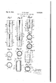
- Fig. 1 is a front view of a tube in accordance with the invention.
- Figs. 2 and 3 are cross-sectional views respectively through lines II--II and III-III of Fig. 1.
- Fig. 4 is a front view showing two tube sections before being fully pulled out.
- Fig. 5 is a cross-sectional view through line V-V of Fig. 4. l
- Fig. 6 is a front View showing two tube sec- 2 tions fully pulled! outand in. ⁇ their locked position.
- Figs. 7 and ⁇ 8 are cross-sectional views respectively through ,lines VII-VII and VIII-VIII of Fig. 6.
- Fig. 9 is an elevational" view showing the stamped abutments'press'edout atY the top of the tubes to avoidth'eir disengagement when the legs are folded up.
- Fig. 10 isa plan thereof.
- Fig. 11 isa View thereof in' longitudinal section through'line KIQ-XI of Fig. 9.
- Each part ofv th'et'elescopic tube orsection 2 (Figs. 1 to 3) is furnished throughout its length with a groove 3 in"th ⁇ e"" ⁇ shape" of a V forming on thel inside of'Y the tubejafprojecting part 4- of the samer shape. It shows-- at its upper end a bulge 5 andv at' its lowerinend twoindentations 6; the depth off the pressed parts 5 yand't is equal to the'r diif'erence'indiameter between two consecutive 'tube'.sections, .but the' projecting part i formed bythe groove is greater than this difference.
- Eachftubef-sliowsanv opening ornotch l 1 cut axially with-reference to the' groove 3 near its lower end, and a second opening or notch 8 offset with reference to the axis of the groove 3 and located near its upper end. rIhe length of each of these openings or notches l and 8 must be respectively equal to or slightly greater than the length of the groove remaining unopened at the other end of the rib on the other side of the other notch.
- Figs. 4 and 5 show the respective positions of these notches in two sections in place but not completely pulled out.
- the notch 'l of the bottom of the outer section and the notch 8' of the top of the inner section 2 partly coincide.
- a telescopic leg chiey for camera stands the combination of two interengaging tube sections each provided with an inwardly directed stamped longitudinal guiding portion tting inside the guiding portion in the other tube and with longitudinal openings registering for one of the sections with a fractional length of the guiding portion therein and shifted laterally for the second section with reference to a fractional length of the corresponding guiding portion and partly overlapping same; the terminal distance between the ends of each tube section facing the other section and the nearest end of the opening in the sections considered being smaller than the length of the opening in the other section for allowing the projection through each opening of the terminal part of the guiding portion in the other section, the first opening allowing a small angular shifting of the guiding portion engaging it and the second opening leaving a fraction of the stamped guiding portion unaltered along its side to serve as an abutment forthe guiding portion of the cooperating tube section.
- a telescopic leg for camera stands comprising a series of interengaging tubes each provided with" an inwardly directed stamped longitudinal guiding portion, the guiding portion of one tube fitting inside the guiding portion of the next tube, each tube being provided with longitudinal openings at a small distancefrom their ends and registering for one end of the tube with a correspending length of the vguiding portion therein and shifted for the other end with reference to a fractional length of the guiding portion while overlapping same, the solid lengths of the guiding portions beyond the openings being shorter than the openings at the cooperating end of the adjacent tube.
Landscapes
- Engineering & Computer Science (AREA)
- Chemical & Material Sciences (AREA)
- Combustion & Propulsion (AREA)
- General Engineering & Computer Science (AREA)
- Mechanical Engineering (AREA)
- Mutual Connection Of Rods And Tubes (AREA)
Applications Claiming Priority (1)
| Application Number | Priority Date | Filing Date | Title |
|---|---|---|---|
| FR872475T | 1940-10-29 |
Publications (1)
| Publication Number | Publication Date |
|---|---|
| US2476216A true US2476216A (en) | 1949-07-12 |
Family
ID=32232298
Family Applications (1)
| Application Number | Title | Priority Date | Filing Date |
|---|---|---|---|
| US741613A Expired - Lifetime US2476216A (en) | 1940-10-29 | 1947-04-15 | Self-locking telescopic stand leg |
Country Status (2)
| Country | Link |
|---|---|
| US (1) | US2476216A (fr) |
| FR (1) | FR872475A (fr) |
Cited By (10)
| Publication number | Priority date | Publication date | Assignee | Title |
|---|---|---|---|---|
| US2750141A (en) * | 1952-11-03 | 1956-06-12 | Herrmann B Tobias | Collapsible stands for cameras and the like |
| US2771261A (en) * | 1950-05-11 | 1956-11-20 | Kuerbi & Niggeloh | Telescoping tripod leg |
| US2915840A (en) * | 1957-04-12 | 1959-12-08 | Airequipt Mfg Co Inc | Automatic actuating mechanism for photographic slides and the like |
| DE1082780B (de) * | 1954-10-11 | 1960-06-02 | Hoover Ltd | Teleskoprohr |
| US3168200A (en) * | 1962-11-26 | 1965-02-02 | Parker Metal Goods Company | Tubular display stand having removable article supports |
| US3435783A (en) * | 1967-08-09 | 1969-04-01 | Cecil L Kollenborn | Adjustable easy chair table |
| US5718266A (en) * | 1995-06-07 | 1998-02-17 | Bondioli; Edi | Tubular component for telescopic propeller shaft |
| US20050080443A1 (en) * | 2003-08-26 | 2005-04-14 | Medicinelodge, Inc. | Bodily tissue dilation systems and methods |
| US10781715B2 (en) * | 2015-12-21 | 2020-09-22 | Raytheon Technologies Corporation | Impingement cooling baffle |
| US20250369472A1 (en) * | 2024-06-04 | 2025-12-04 | Gem Products, Llc | Telescopic tube assembly |
Citations (1)
| Publication number | Priority date | Publication date | Assignee | Title |
|---|---|---|---|---|
| DE581685C (de) * | 1932-06-23 | 1933-08-01 | Auguste Dupeyron | Ausziehrohr, insbesondere fuer Stative |
-
1940
- 1940-10-29 FR FR872475D patent/FR872475A/fr not_active Expired
-
1947
- 1947-04-15 US US741613A patent/US2476216A/en not_active Expired - Lifetime
Patent Citations (1)
| Publication number | Priority date | Publication date | Assignee | Title |
|---|---|---|---|---|
| DE581685C (de) * | 1932-06-23 | 1933-08-01 | Auguste Dupeyron | Ausziehrohr, insbesondere fuer Stative |
Cited By (11)
| Publication number | Priority date | Publication date | Assignee | Title |
|---|---|---|---|---|
| US2771261A (en) * | 1950-05-11 | 1956-11-20 | Kuerbi & Niggeloh | Telescoping tripod leg |
| US2750141A (en) * | 1952-11-03 | 1956-06-12 | Herrmann B Tobias | Collapsible stands for cameras and the like |
| DE1082780B (de) * | 1954-10-11 | 1960-06-02 | Hoover Ltd | Teleskoprohr |
| US2915840A (en) * | 1957-04-12 | 1959-12-08 | Airequipt Mfg Co Inc | Automatic actuating mechanism for photographic slides and the like |
| US3168200A (en) * | 1962-11-26 | 1965-02-02 | Parker Metal Goods Company | Tubular display stand having removable article supports |
| US3435783A (en) * | 1967-08-09 | 1969-04-01 | Cecil L Kollenborn | Adjustable easy chair table |
| US5718266A (en) * | 1995-06-07 | 1998-02-17 | Bondioli; Edi | Tubular component for telescopic propeller shaft |
| US20050080443A1 (en) * | 2003-08-26 | 2005-04-14 | Medicinelodge, Inc. | Bodily tissue dilation systems and methods |
| US7811303B2 (en) * | 2003-08-26 | 2010-10-12 | Medicine Lodge Inc | Bodily tissue dilation systems and methods |
| US10781715B2 (en) * | 2015-12-21 | 2020-09-22 | Raytheon Technologies Corporation | Impingement cooling baffle |
| US20250369472A1 (en) * | 2024-06-04 | 2025-12-04 | Gem Products, Llc | Telescopic tube assembly |
Also Published As
| Publication number | Publication date |
|---|---|
| FR872475A (fr) | 1942-06-11 |
Similar Documents
| Publication | Publication Date | Title |
|---|---|---|
| US2476216A (en) | Self-locking telescopic stand leg | |
| EP0139954B1 (fr) | Echafaudage à barres détachables | |
| DE102015212769B4 (de) | Einstellmechanismus und damit versehener Kindersitz | |
| DE2755527C2 (fr) | ||
| DE9102718U1 (de) | Kombination aus mindestens zwei, je einen Werkzeug-Satz aufnehmenden Teilkoffern | |
| DE69011499T2 (de) | Konstruktion zum Stützen von Gleitschienen für Schubladen, insbesondere für industrielle Kühlschränke. | |
| DE19944640A1 (de) | Ausziehführungsgarnitur | |
| DE3807028C1 (en) | Telescopic tube connection | |
| DE2701470A1 (de) | Fuehrungselement fuer schubfach und gestell mit einem solchen element | |
| DE2008785B2 (de) | Profilleiste zur verbindung zweier waende oder platten | |
| DE8504841U1 (de) | Briefablage-Box | |
| EP0481357B1 (fr) | Poignée pour la construction de machines et d'outils | |
| DE2213019A1 (fr) | ||
| DE2828905C2 (de) | Verbundprofil bestehend aus zwei zueinander parallelen Metallteilen | |
| DE393629C (de) | Patronenmagazin | |
| DE8109516U1 (de) | Schubladen-magazin, insbesondere fuer die vorratshaltung und/oder lagerung von kleinteilen | |
| DE7207013U (de) | Messer mit regulierbarer vorspringender klinge | |
| DE349988C (de) | Zusammensetzbarer Schrank aus Blech zur Aufnahme von Schubkaesten, Schubfaechern u. dgl. | |
| DE583423C (de) | Ausziehrohr, insbesondere fuer Stative | |
| CH539190A (de) | Rollvorhang oder aufrollbare Unterlage aus Hohlprofilleisten | |
| DE569085C (de) | Ausziehrohr, insbesondere fuer Stative | |
| DE3516409C2 (fr) | ||
| DE621730C (de) | Wanddurchfuehrung fuer Rohre, bei der das Rohr durch Kugeln in der Durchfuehrung zentrisch gehalten wird | |
| DE3504524C2 (fr) | ||
| DE548586C (de) | Verfahren zur Herstellung von Filmspulen aus Blech |