US11589856B2 - Clip applier and methods of use - Google Patents
Clip applier and methods of use Download PDFInfo
- Publication number
- US11589856B2 US11589856B2 US16/531,790 US201916531790A US11589856B2 US 11589856 B2 US11589856 B2 US 11589856B2 US 201916531790 A US201916531790 A US 201916531790A US 11589856 B2 US11589856 B2 US 11589856B2
- Authority
- US
- United States
- Prior art keywords
- assembly
- carrier
- end region
- closure element
- distal end
- Prior art date
- Legal status (The legal status is an assumption and is not a legal conclusion. Google has not performed a legal analysis and makes no representation as to the accuracy of the status listed.)
- Expired - Lifetime, expires
Links
- 238000000034 method Methods 0.000 title description 114
- 239000000463 material Substances 0.000 claims description 71
- 230000007704 transition Effects 0.000 claims description 52
- 210000004204 blood vessel Anatomy 0.000 description 235
- 230000023597 hemostasis Effects 0.000 description 168
- 230000002829 reductive effect Effects 0.000 description 39
- 230000006870 function Effects 0.000 description 35
- 230000000717 retained effect Effects 0.000 description 30
- 230000007246 mechanism Effects 0.000 description 21
- 230000008878 coupling Effects 0.000 description 19
- 238000010168 coupling process Methods 0.000 description 19
- 238000005859 coupling reaction Methods 0.000 description 19
- 230000009286 beneficial effect Effects 0.000 description 15
- 230000002439 hemostatic effect Effects 0.000 description 15
- 230000001976 improved effect Effects 0.000 description 15
- 230000008569 process Effects 0.000 description 15
- 238000007789 sealing Methods 0.000 description 15
- 238000004891 communication Methods 0.000 description 14
- 229910001000 nickel titanium Inorganic materials 0.000 description 14
- 229910052751 metal Inorganic materials 0.000 description 12
- 239000002184 metal Substances 0.000 description 12
- 230000000712 assembly Effects 0.000 description 11
- 238000000429 assembly Methods 0.000 description 11
- HLXZNVUGXRDIFK-UHFFFAOYSA-N nickel titanium Chemical compound [Ti].[Ti].[Ti].[Ti].[Ti].[Ti].[Ti].[Ti].[Ti].[Ti].[Ti].[Ni].[Ni].[Ni].[Ni].[Ni].[Ni].[Ni].[Ni].[Ni].[Ni].[Ni].[Ni].[Ni].[Ni] HLXZNVUGXRDIFK-UHFFFAOYSA-N 0.000 description 11
- 230000008859 change Effects 0.000 description 10
- 230000000694 effects Effects 0.000 description 10
- 239000004033 plastic Substances 0.000 description 10
- 229920003023 plastic Polymers 0.000 description 10
- 210000004369 blood Anatomy 0.000 description 9
- 239000008280 blood Substances 0.000 description 9
- 239000012530 fluid Substances 0.000 description 9
- 230000003068 static effect Effects 0.000 description 9
- 230000003213 activating effect Effects 0.000 description 8
- 239000000853 adhesive Substances 0.000 description 8
- 230000001070 adhesive effect Effects 0.000 description 8
- 229920000642 polymer Polymers 0.000 description 8
- 238000013459 approach Methods 0.000 description 7
- 238000002405 diagnostic procedure Methods 0.000 description 7
- 125000006850 spacer group Chemical group 0.000 description 7
- 238000002560 therapeutic procedure Methods 0.000 description 7
- 229910045601 alloy Inorganic materials 0.000 description 6
- 239000000956 alloy Substances 0.000 description 6
- 238000013461 design Methods 0.000 description 6
- 230000014759 maintenance of location Effects 0.000 description 6
- 150000002739 metals Chemical class 0.000 description 6
- 239000012781 shape memory material Substances 0.000 description 6
- 229910001285 shape-memory alloy Inorganic materials 0.000 description 6
- 239000004677 Nylon Substances 0.000 description 5
- 230000008901 benefit Effects 0.000 description 5
- 230000000994 depressogenic effect Effects 0.000 description 5
- 238000006073 displacement reaction Methods 0.000 description 5
- 229920001778 nylon Polymers 0.000 description 5
- 230000009471 action Effects 0.000 description 4
- 229940030225 antihemorrhagics Drugs 0.000 description 4
- 230000000295 complement effect Effects 0.000 description 4
- 239000004020 conductor Substances 0.000 description 4
- 229910003460 diamond Inorganic materials 0.000 description 4
- 239000010432 diamond Substances 0.000 description 4
- 238000002594 fluoroscopy Methods 0.000 description 4
- 239000003292 glue Substances 0.000 description 4
- 239000002874 hemostatic agent Substances 0.000 description 4
- 238000003384 imaging method Methods 0.000 description 4
- 238000002513 implantation Methods 0.000 description 4
- 238000013152 interventional procedure Methods 0.000 description 4
- 239000000203 mixture Substances 0.000 description 4
- 230000035515 penetration Effects 0.000 description 4
- 230000002093 peripheral effect Effects 0.000 description 4
- 238000005381 potential energy Methods 0.000 description 4
- 239000010935 stainless steel Substances 0.000 description 4
- 229910001220 stainless steel Inorganic materials 0.000 description 4
- 230000008093 supporting effect Effects 0.000 description 4
- HZEWFHLRYVTOIW-UHFFFAOYSA-N [Ti].[Ni] Chemical compound [Ti].[Ni] HZEWFHLRYVTOIW-UHFFFAOYSA-N 0.000 description 3
- 238000002399 angioplasty Methods 0.000 description 3
- 239000000919 ceramic Substances 0.000 description 3
- 239000002131 composite material Substances 0.000 description 3
- 230000002401 inhibitory effect Effects 0.000 description 3
- 238000003780 insertion Methods 0.000 description 3
- 230000037431 insertion Effects 0.000 description 3
- 230000000670 limiting effect Effects 0.000 description 3
- 238000005259 measurement Methods 0.000 description 3
- 238000012986 modification Methods 0.000 description 3
- 230000004048 modification Effects 0.000 description 3
- 230000036961 partial effect Effects 0.000 description 3
- 230000001681 protective effect Effects 0.000 description 3
- 230000002792 vascular Effects 0.000 description 3
- 210000005166 vasculature Anatomy 0.000 description 3
- 208000032843 Hemorrhage Diseases 0.000 description 2
- 238000005452 bending Methods 0.000 description 2
- 230000000740 bleeding effect Effects 0.000 description 2
- 210000001124 body fluid Anatomy 0.000 description 2
- 239000010839 body fluid Substances 0.000 description 2
- 210000001715 carotid artery Anatomy 0.000 description 2
- 239000003795 chemical substances by application Substances 0.000 description 2
- 230000006835 compression Effects 0.000 description 2
- 238000007906 compression Methods 0.000 description 2
- 230000008602 contraction Effects 0.000 description 2
- 239000013078 crystal Substances 0.000 description 2
- 238000010586 diagram Methods 0.000 description 2
- 210000001105 femoral artery Anatomy 0.000 description 2
- 238000002847 impedance measurement Methods 0.000 description 2
- 239000012212 insulator Substances 0.000 description 2
- 230000013011 mating Effects 0.000 description 2
- 238000012544 monitoring process Methods 0.000 description 2
- 230000000149 penetrating effect Effects 0.000 description 2
- 210000005259 peripheral blood Anatomy 0.000 description 2
- 239000011886 peripheral blood Substances 0.000 description 2
- 230000009467 reduction Effects 0.000 description 2
- 230000002787 reinforcement Effects 0.000 description 2
- 230000002441 reversible effect Effects 0.000 description 2
- 230000001225 therapeutic effect Effects 0.000 description 2
- 206010053567 Coagulopathies Diseases 0.000 description 1
- 206010018852 Haematoma Diseases 0.000 description 1
- 239000004698 Polyethylene Substances 0.000 description 1
- 229910000639 Spring steel Inorganic materials 0.000 description 1
- 229910000831 Steel Inorganic materials 0.000 description 1
- 241000950638 Symphysodon discus Species 0.000 description 1
- 241000219793 Trifolium Species 0.000 description 1
- 206010052428 Wound Diseases 0.000 description 1
- 208000027418 Wounds and injury Diseases 0.000 description 1
- 230000002411 adverse Effects 0.000 description 1
- 239000000560 biocompatible material Substances 0.000 description 1
- 229920000249 biocompatible polymer Polymers 0.000 description 1
- 230000017531 blood circulation Effects 0.000 description 1
- 238000005219 brazing Methods 0.000 description 1
- 238000006243 chemical reaction Methods 0.000 description 1
- 230000035602 clotting Effects 0.000 description 1
- 238000000576 coating method Methods 0.000 description 1
- 238000010276 construction Methods 0.000 description 1
- 230000007423 decrease Effects 0.000 description 1
- 230000003247 decreasing effect Effects 0.000 description 1
- 229920006237 degradable polymer Polymers 0.000 description 1
- 230000000881 depressing effect Effects 0.000 description 1
- 238000001514 detection method Methods 0.000 description 1
- 230000001627 detrimental effect Effects 0.000 description 1
- 230000005489 elastic deformation Effects 0.000 description 1
- 229920001971 elastomer Polymers 0.000 description 1
- 239000000806 elastomer Substances 0.000 description 1
- 230000001747 exhibiting effect Effects 0.000 description 1
- 230000002349 favourable effect Effects 0.000 description 1
- 210000003746 feather Anatomy 0.000 description 1
- 210000003811 finger Anatomy 0.000 description 1
- 239000006260 foam Substances 0.000 description 1
- 238000009998 heat setting Methods 0.000 description 1
- 239000000017 hydrogel Substances 0.000 description 1
- 208000014674 injury Diseases 0.000 description 1
- 239000011810 insulating material Substances 0.000 description 1
- 230000003993 interaction Effects 0.000 description 1
- HOQADATXFBOEGG-UHFFFAOYSA-N isofenphos Chemical compound CCOP(=S)(NC(C)C)OC1=CC=CC=C1C(=O)OC(C)C HOQADATXFBOEGG-UHFFFAOYSA-N 0.000 description 1
- 238000002955 isolation Methods 0.000 description 1
- 229920003052 natural elastomer Polymers 0.000 description 1
- 229920001194 natural rubber Polymers 0.000 description 1
- OCDRLZFZBHZTKQ-NMUBGGKPSA-N onetine Chemical compound C[C@@H](O)[C@@]1(O)C[C@@H](C)[C@@](C)(O)C(=O)OC\C2=C\CN(C)CC[C@@H](OC1=O)C2=O OCDRLZFZBHZTKQ-NMUBGGKPSA-N 0.000 description 1
- -1 polyethylene Polymers 0.000 description 1
- 229920000573 polyethylene Polymers 0.000 description 1
- 230000011514 reflex Effects 0.000 description 1
- 230000003014 reinforcing effect Effects 0.000 description 1
- 230000004044 response Effects 0.000 description 1
- 230000000452 restraining effect Effects 0.000 description 1
- 238000000926 separation method Methods 0.000 description 1
- 229920000431 shape-memory polymer Polymers 0.000 description 1
- 238000005245 sintering Methods 0.000 description 1
- 239000008247 solid mixture Substances 0.000 description 1
- 239000010959 steel Substances 0.000 description 1
- 239000003356 suture material Substances 0.000 description 1
- 229920003051 synthetic elastomer Polymers 0.000 description 1
- 239000005061 synthetic rubber Substances 0.000 description 1
- 230000000930 thermomechanical effect Effects 0.000 description 1
- 210000003813 thumb Anatomy 0.000 description 1
- 230000008733 trauma Effects 0.000 description 1
- 238000003466 welding Methods 0.000 description 1
Images


Classifications
-
- A—HUMAN NECESSITIES
- A61—MEDICAL OR VETERINARY SCIENCE; HYGIENE
- A61B—DIAGNOSIS; SURGERY; IDENTIFICATION
- A61B17/00—Surgical instruments, devices or methods, e.g. tourniquets
- A61B17/0057—Implements for plugging an opening in the wall of a hollow or tubular organ, e.g. for sealing a vessel puncture or closing a cardiac septal defect
-
- A—HUMAN NECESSITIES
- A61—MEDICAL OR VETERINARY SCIENCE; HYGIENE
- A61B—DIAGNOSIS; SURGERY; IDENTIFICATION
- A61B17/00—Surgical instruments, devices or methods, e.g. tourniquets
- A61B17/064—Surgical staples, i.e. penetrating the tissue
-
- A—HUMAN NECESSITIES
- A61—MEDICAL OR VETERINARY SCIENCE; HYGIENE
- A61B—DIAGNOSIS; SURGERY; IDENTIFICATION
- A61B17/00—Surgical instruments, devices or methods, e.g. tourniquets
- A61B17/068—Surgical staplers, e.g. containing multiple staples or clamps
-
- A—HUMAN NECESSITIES
- A61—MEDICAL OR VETERINARY SCIENCE; HYGIENE
- A61B—DIAGNOSIS; SURGERY; IDENTIFICATION
- A61B17/00—Surgical instruments, devices or methods, e.g. tourniquets
- A61B17/10—Surgical instruments, devices or methods, e.g. tourniquets for applying or removing wound clamps, e.g. containing only one clamp or staple; Wound clamp magazines
-
- A—HUMAN NECESSITIES
- A61—MEDICAL OR VETERINARY SCIENCE; HYGIENE
- A61B—DIAGNOSIS; SURGERY; IDENTIFICATION
- A61B17/00—Surgical instruments, devices or methods, e.g. tourniquets
- A61B17/064—Surgical staples, i.e. penetrating the tissue
- A61B17/0644—Surgical staples, i.e. penetrating the tissue penetrating the tissue, deformable to closed position
-
- A—HUMAN NECESSITIES
- A61—MEDICAL OR VETERINARY SCIENCE; HYGIENE
- A61B—DIAGNOSIS; SURGERY; IDENTIFICATION
- A61B17/00—Surgical instruments, devices or methods, e.g. tourniquets
- A61B17/08—Wound clamps or clips, i.e. not or only partly penetrating the tissue ; Devices for bringing together the edges of a wound
- A61B17/083—Clips, e.g. resilient
-
- A—HUMAN NECESSITIES
- A61—MEDICAL OR VETERINARY SCIENCE; HYGIENE
- A61B—DIAGNOSIS; SURGERY; IDENTIFICATION
- A61B17/00—Surgical instruments, devices or methods, e.g. tourniquets
- A61B17/12—Surgical instruments, devices or methods, e.g. tourniquets for ligaturing or otherwise compressing tubular parts of the body, e.g. blood vessels, umbilical cord
- A61B17/122—Clamps or clips, e.g. for the umbilical cord
- A61B17/1227—Spring clips
-
- A—HUMAN NECESSITIES
- A61—MEDICAL OR VETERINARY SCIENCE; HYGIENE
- A61B—DIAGNOSIS; SURGERY; IDENTIFICATION
- A61B17/00—Surgical instruments, devices or methods, e.g. tourniquets
- A61B2017/00017—Electrical control of surgical instruments
- A61B2017/00022—Sensing or detecting at the treatment site
- A61B2017/00026—Conductivity or impedance, e.g. of tissue
- A61B2017/0003—Conductivity or impedance, e.g. of tissue of parts of the instruments
-
- A—HUMAN NECESSITIES
- A61—MEDICAL OR VETERINARY SCIENCE; HYGIENE
- A61B—DIAGNOSIS; SURGERY; IDENTIFICATION
- A61B17/00—Surgical instruments, devices or methods, e.g. tourniquets
- A61B2017/00017—Electrical control of surgical instruments
- A61B2017/00022—Sensing or detecting at the treatment site
- A61B2017/00106—Sensing or detecting at the treatment site ultrasonic
-
- A—HUMAN NECESSITIES
- A61—MEDICAL OR VETERINARY SCIENCE; HYGIENE
- A61B—DIAGNOSIS; SURGERY; IDENTIFICATION
- A61B17/00—Surgical instruments, devices or methods, e.g. tourniquets
- A61B17/00234—Surgical instruments, devices or methods, e.g. tourniquets for minimally invasive surgery
- A61B2017/00349—Needle-like instruments having hook or barb-like gripping means, e.g. for grasping suture or tissue
-
- A—HUMAN NECESSITIES
- A61—MEDICAL OR VETERINARY SCIENCE; HYGIENE
- A61B—DIAGNOSIS; SURGERY; IDENTIFICATION
- A61B17/00—Surgical instruments, devices or methods, e.g. tourniquets
- A61B17/0057—Implements for plugging an opening in the wall of a hollow or tubular organ, e.g. for sealing a vessel puncture or closing a cardiac septal defect
- A61B2017/00637—Implements for plugging an opening in the wall of a hollow or tubular organ, e.g. for sealing a vessel puncture or closing a cardiac septal defect for sealing trocar wounds through abdominal wall
-
- A—HUMAN NECESSITIES
- A61—MEDICAL OR VETERINARY SCIENCE; HYGIENE
- A61B—DIAGNOSIS; SURGERY; IDENTIFICATION
- A61B17/00—Surgical instruments, devices or methods, e.g. tourniquets
- A61B17/0057—Implements for plugging an opening in the wall of a hollow or tubular organ, e.g. for sealing a vessel puncture or closing a cardiac septal defect
- A61B2017/00646—Type of implements
- A61B2017/00668—Type of implements the implement being a tack or a staple
-
- A—HUMAN NECESSITIES
- A61—MEDICAL OR VETERINARY SCIENCE; HYGIENE
- A61B—DIAGNOSIS; SURGERY; IDENTIFICATION
- A61B17/00—Surgical instruments, devices or methods, e.g. tourniquets
- A61B17/0057—Implements for plugging an opening in the wall of a hollow or tubular organ, e.g. for sealing a vessel puncture or closing a cardiac septal defect
- A61B2017/00672—Locating means therefor, e.g. bleed back lumen
-
- A—HUMAN NECESSITIES
- A61—MEDICAL OR VETERINARY SCIENCE; HYGIENE
- A61B—DIAGNOSIS; SURGERY; IDENTIFICATION
- A61B17/00—Surgical instruments, devices or methods, e.g. tourniquets
- A61B17/064—Surgical staples, i.e. penetrating the tissue
- A61B2017/0649—Coils or spirals
-
- A—HUMAN NECESSITIES
- A61—MEDICAL OR VETERINARY SCIENCE; HYGIENE
- A61B—DIAGNOSIS; SURGERY; IDENTIFICATION
- A61B17/00—Surgical instruments, devices or methods, e.g. tourniquets
- A61B17/12—Surgical instruments, devices or methods, e.g. tourniquets for ligaturing or otherwise compressing tubular parts of the body, e.g. blood vessels, umbilical cord
- A61B17/12009—Implements for ligaturing other than by clamps or clips, e.g. using a loop with a slip knot
- A61B2017/12018—Elastic band ligators
-
- A—HUMAN NECESSITIES
- A61—MEDICAL OR VETERINARY SCIENCE; HYGIENE
- A61B—DIAGNOSIS; SURGERY; IDENTIFICATION
- A61B90/00—Instruments, implements or accessories specially adapted for surgery or diagnosis and not covered by any of the groups A61B1/00 - A61B50/00, e.g. for luxation treatment or for protecting wound edges
- A61B90/06—Measuring instruments not otherwise provided for
- A61B2090/064—Measuring instruments not otherwise provided for for measuring force, pressure or mechanical tension
- A61B2090/065—Measuring instruments not otherwise provided for for measuring force, pressure or mechanical tension for measuring contact or contact pressure
Definitions
- the present invention relates generally to apparatus and methods for closing and/or sealing openings through tissue, and more particularly to apparatus and methods for delivering a closure element for closing a puncture in a blood vessel or other body lumen formed during a diagnostic or therapeutic procedure.
- Catheterization and interventional procedures such as angioplasty or stenting, generally are performed by inserting a hollow needle through a patient's skin and tissue into the vascular system.
- a guide wire may be advanced through the needle and into the patient's blood vessel accessed by the needle.
- the needle then is removed, enabling an introducer sheath to be advanced over the guide wire into the vessel, e.g., in conjunction with or subsequent to a dilator.
- a catheter or other device may then be advanced through a lumen of the introducer sheath and over the guide wire into a position for performing a medical procedure.
- the introducer sheath may facilitate introducing various devices into the vessel, while minimizing trauma to the vessel wall and/or minimizing blood loss during a procedure.
- the devices and introducer sheath may be removed, leaving a puncture site in the vessel wall. External pressure may be applied to the puncture site until clotting and wound sealing occur.
- This procedure may be time consuming and expensive, requiring as much as an hour of a physician's or nurse's time. It is also uncomfortable for the patient, and requires that the patient remain immobilized in the operating room, catheter lab, or holding area. In addition, a risk of hematoma exists from bleeding before hemostasis occurs.
- bleed back indicators To facilitate positioning devices that are percutaneously inserted into a blood vessel, “bleed back” indicators have been suggested.
- U.S. Pat. No. 5,676,974 issued to Kensey et al., discloses a bleed back lumen intended to facilitate positioning of a biodegradable plug within a puncture site. This device, however, requires that an anchor of the plug be positioned within the vessel, and therefore, may increase the risk of over-advancement of the plug itself into the vessel.
- U.S. Pat. No. 5,674,231 issued to Green et al., discloses a deployable loop that may be advanced through a sheath into a vessel.
- the loop is intended to resiliently expand to engage the inner wall of the vessel, thereby facilitating holding the sheath in a desired location with respect to the vessel. Accordingly, apparatus and methods for delivering a device for closing a vascular puncture site or other opening through tissue would be useful.
- the present invention is directed toward an apparatus and method for delivering a closure element (e.g., clip) through tissue and into an opening formed in, or adjacent to, a wall of a blood vessel or other body lumen of any size.
- a closure element e.g., clip
- an embodiment of such a clip applier apparatus can include a carrier tube carrying a closure element and a splitter configured to split the carrier tube.
- the carrier tube can have an outer surface retaining the closure element in a substantially tubular configuration.
- the carrier tube can be configured to split into radially-expandable or outwardly bendable carrier flaps.
- the splitter can be disposed distally from the carrier tube, and can be configured to move into a lumen of the carrier tube.
- the splitter can be disposed in a distal end of the lumen of the carrier tube.
- the splitter can split the carrier tube into the radially-expandable or outwardly bendable carrier flaps when moved through the lumen of the carrier tube.
- the splitter can have a proximal end with a cross-sectional profile smaller than a cross-sectional profile of a distal end.
- a clip applier apparatus for delivering a closure element to an opening formed in a wall of a body lumen or body tissue can include a slidable splitter or an expandable splitter.
- the carrier tube can have an outer surface retaining the closure element in a substantially tubular configuration.
- the carrier tube can have a lumen and slits at a distal end of the carrier tube.
- the carrier tube can be configured to split at the slits so as to form outwardly bendable carrier flaps.
- the splitter can be disposed adjacent to the slits so that the splitter can split the carrier tube at the distal end to form and outwardly bend the carrier flaps.
- the apparatus can include a splittable pusher tube that splits similarly as the carrier tube.
- the pusher tube can be configured to split into radially-expandable or outwardly bendable pusher flaps by the splitter when moved distally with respect to the carrier tube to deploy the closure element over the radially-expandable or outwardly bendable carrier flaps after expanding over the splitter.
- the expandable splitter can expand to split the pusher tube in order to form the pusher flaps.
- a clip applier apparatus for delivering a closure element to an opening formed in a wall of a body lumen or body tissue can include at least a partially splittable carrier tube and a splitter.
- a clip applier apparatus can include a partially splittable carrier tube having a length and slits extending at least partially along the length from a distal end toward a proximal end. The slits can be configured to separate at a distal portion of the carrier tube to form carrier flaps.
- the carrier tube can have an outer surface retaining a closure element in a substantially tubular configuration at the splittable distal portion.
- the splitter can be configured to move into a lumen of the carrier tube so as to split the distal portion of the carrier tube into the carrier flaps.
- the splitter can have a proximal end with a cross-sectional profile smaller than a cross-sectional profile of a distal end.
- at least the distal end of the splitter can be larger than the lumen of the carrier tube.
- the splitter can be an expandable splitter. As such, the entire splitter can selectively expand to split the carrier tube into the carrier flaps. Alternatively, the distal end of the splitter can selectively expand to split the carrier tube into the carrier flaps.
- the splitter can be coupled to a support tube so as to form a splitter tube.
- the splitter can be coupled to a wire disposed within the lumen of the carrier tube.
- the wire can extend through a passage in the splitter and have an end with an expanded diameter or retaining element disposed within a cavity in the splitter so that the end cannot pass through the passage.
- a slidable splitter can be planar or volumetric, and can be shaped as at least one of a cone, wedge, sphere, hemisphere, trapezoid, combinations thereof, or other configurations that allow the splitter to perform the functions described herein.
- the splitter can include a series of combinable splitters, wherein proximally disposed combinable splitters each have a recess for receiving a proximal portion of a distally-adjacent combinable splitter.
- the splitter can include at least a proximal combinable splitter and a distal combinable splitter, wherein the proximal combinable splitter has a recess for receiving a proximal end of the distal combinable splitter.
- the splitter can be adapted to take hold of or grab a portion of tissue to the splitter.
- the splitter can include teeth, barbs, or other structures that enable tissue to be selectively secured to a portion of the splitter.
- the present invention can use a clip applier having a carrier tube and a splitter in a method for closing an opening formed in a wall of a body lumen or body tissue.
- a method can include the following: positioning a carrier tube adjacent to the opening, the carrier tube having a distal end with an outer surface retaining a closure element in a substantially tubular configuration, the carrier tube having a lumen and being configured to split into flaps; splitting a distal end of the carrier tube with a splitter so as to form the flaps that deform outwardly over the splitter; and deploying the closure element from the outwardly deformed flaps of the carrier tube and over the splitter so that the closure element engages at least a portion of the wall of the body lumen or the body tissue whereby the opening is drawn substantially closed.
- the carrier tube can be split with the splitter by at least one of the following: moving the splitter proximally with respect to the carrier tube; moving the carrier tube distally with respect to the splitter, or simultaneously moving the splitter proximally with respect to the carrier tube and moving the carrier tube distally with respect to the splitter; expanding the splitter; or selectively expanding a distal portion of the splitter.
- a tissue-grabbing splitter can be used in a method for closing an opening formed in a wall of a body lumen or body tissue.
- a method for closing an opening formed in a wall of a body lumen or body tissue can include grabbing tissue around the opening with teeth and/or barbs on the splitter, and drawing the grabbed tissue toward the opening when the splitter is being pulled therethrough.
- the present invention is also directed toward an apparatus and method for delivering a closure element through tissue and into an opening formed in, or adjacent to, a wall of a blood vessel or other body lumen of any size. It is further contemplated that the closure element and devices described herein can be utilized for other medical procedures not described herein, and it shall be further understood that the methods described herein should be considered exemplary and not limiting.
- an embodiment of a closure element in accordance with the present can include a clip for closing an opening formed in a wall of a body lumen or body tissue.
- a clip can include a shape-memory clip having a relaxed configuration with a substantially planar-annular body defining a lumen with a plurality of tines directed inwardly from the body.
- the clip can be oriented and held by a clip applier in a retaining configuration having a substantially asymmetrically-elongated tubular shape with a substantially trapezoidal longitudinal cross-sectional profile and a body portion having the plurality of tines being longitudinally and distally directed with a first tine of the plurality being more distally oriented compared to a substantially opposite second tine being more proximal.
- the clip can be capable of retracting to a deploying configuration having a substantially symmetrical tubular shape with a substantially rectangular longitudinal cross-sectional profile with the first tine being substantially even with the second tine when the clip is being delivered from the clip applier to close the opening.
- the clip in the retaining configuration can have a lumen that has a smaller orthogonal cross-sectional profile (e.g., orthogonal to longitudinal direction) compared to the lumen in the deploying configuration.
- the clip in the retaining configuration can have a lumen that has a more oval orthogonal cross-sectional profile compared to the lumen in the deploying configuration having a more circular orthogonal cross-sectional profile.
- the clip can automatically retract from the retaining configuration to the deploying configuration when being released from the clip applier. Further, the clip can automatically convert to the relaxed configuration from the deploying configuration after being released from the clip applier.
- the present invention can include a clip applier apparatus for delivering a clip to an opening formed in a wall of a body lumen or body tissue.
- a clip applier can include a shape-memory clip as described herein.
- the clip applier can include a carrier tube having an outer surface configured for slidably retaining the clip in a retaining configuration and slidably delivering the clip in a deploying configuration, wherein the retaining configuration and deploying configuration are described herein.
- the clip applier can include a pusher tube that can push the clip from the retaining configuration to the deploying configuration. Also, the pusher tube can be configured to distally push the clip in the retaining configuration over the carrier tube toward a distal end of the carrier tube. Further, the pusher tube can be configured to distally push the clip over a distal end of the carrier tube so that the clip retracts from the retaining configuration to the deploying configuration.
- the carrier tube can be configured so that the outer surface corresponds in shape and size with the lumen of the clip in the retaining configuration. Accordingly, the outer surface of the carrier tube can be generally oval in shape. Also, the outer surface can have a smaller orthogonal cross-sectional profile compared to the size of the lumen of the clip in the deploying configuration.
- the clip applier can include a clip expander that is capable of expanding the clip during deployment.
- the clip expander can be a selectively expandable shape-memory clip expander.
- the clip expander can be disposed at a distal portion of the carrier tube.
- the clip applier can include a cover tube that contains any of the carrier tube, pusher tube, clip, and/or clip expander.
- the cover tube can define a lumen that retains the clip in the retaining configuration.
- the lumen of the cover tube can retain the clip expander in a contracted orientation so that the clip expander can be capable of expanding when moved distally past a distal end of the cover tube.
- Another embodiment of the present invention can include a method for closing an opening formed in a wall of a body lumen or body tissue.
- a method for closing an opening formed in a wall of a body lumen or body tissue can include positioning a carrier tube adjacent to the opening, wherein the carrier tube has a distal portion with an outer surface retaining a shape-memory clip in a retaining configuration.
- the carrier tube, clip, and retaining configuration can be as described herein.
- the method can include pushing the clip over a distal end of the carrier tube so that the clip retracts to a deploying configuration, wherein the deploying configuration is described herein.
- the method can include ejecting the clip from the carrier tube so that at least a portion of the plurality of tines disposed on the body portion of the clip engages a portion of the wall of the body lumen or the body tissue whereby the opening is drawn substantially closed.
- the method can include pushing the clip toward the distal end of the carrier tube with a pusher tube being configured to distally push the clip in the retaining configuration. Also, the method can include flattening the clip, after being deployed from the carrier tube, to a relaxed configuration with a substantially planar-annular body defining a lumen with a plurality of tines directed inwardly from the body of the clip, wherein at least a portion of the tines have inwardly drawn a portion of the wall of the body lumen or the body tissue so as to substantially close the opening.
- the method can include expanding the clip from the retaining configuration having a lumen with a smaller orthogonal cross-sectional profile to the deploying configuration so that the lumen has a larger orthogonal cross-sectional profile.
- the clip can be expanded by a selectively expandable shape-memory clip expander.
- the method can include expanding the clip from the retaining configuration having a lumen with a more oval orthogonal cross-sectional profile to the deploying configuration so that the lumen has a more circular orthogonal cross-sectional profile.
- An embodiment of an apparatus for locating a surface of a body lumen includes a locator assembly that has a distal end region configured to extend into an opening of the body lumen and to selectably engage at least a portion of the body lumen adjacent to the opening.
- the distal end region includes at least one surface engaging element that is configured to engage the surface of the body lumen.
- the apparatus includes a measuring device that is in electrical communication with the surface engaging element. The measuring device is configured to determine changes in measurable characteristics of the surface engaging element.
- An embodiment of a method for locating a surface of a body lumen includes inserting a locator assembly through an opening of the body lumen.
- the locator assembly includes a distal end region having a surface engaging element configured to selectively engage the surface of the body lumen.
- the locator assembly is positioned in close proximity to the opening of the body lumen.
- a measurable characteristic of the surface engaging element is measured within the body lumen. It is determined whether the measurable characteristic of the surface engaging element indicates that the surface engaging element has engaged the surface of the body lumen.
- the surface engaging element includes a proximal end portion that has at least one retaining portion.
- the surface engaging element includes a distal end portion that has at least one retaining portion.
- the surface engaging element includes at least one engaging member that extends toward the proximal end portion and extends toward the distal end portion.
- the at least one engaging member is configured to engage a surface of a body lumen.
- the present invention includes an apparatus for positioning a closure element to close an opening in a body lumen.
- Such an apparatus includes a carrier assembly and a distal tissue engaging device.
- the carrier assembly is configured to support a closure element in a substantially tubular configuration in a first diameter.
- the closure element is configured to substantially uniformly deform from a substantially tubular configuration to a natural, substantially planar configuration.
- the distal tissue engaging device is selectably axially displaceable relative to at least a portion of the carrier assembly. As such, the distal tissue engaging device moves between a tissue engaging condition and a tissue closing condition.
- the tissue engaging condition engages opposing portions of an arterial wall defining said body lumen adjacent to the opening.
- the tissue closing condition urges the engaged opposing portions of the arterial wall substantially together such that the closure element may be deployed from the delivery assembly to engage the opposed portions of the arterial wall and to return to the natural, substantially planar configuration.
- the distal tissue engaging device includes two or more opposed engaging tongs having respective end tips configured to open radially in directions extending beyond the first diameter to initially engage the opposing portions of the arterial wall, in the engaging condition.
- the carrier assembly further includes a cover member protecting at least the closure element which is contained therein.
- the distal tissue engaging device is integral with a distal end of the cover member.
- the carrier assembly is formed and dimensioned for sliding axial, reciprocating, receipt in a lumen of an introducer sheath extending through said tissue and terminating proximate the opening.
- the tissue engaging device is configured to cooperate with the introducer sheath to enable movement between the engaging condition and the closing condition.
- the present invention includes an apparatus for delivering and deploying a substantially resilient closure element through tissue to an opening in a body lumen perimeterically defined by opposing arterial walls.
- the closure element is configured to substantially uniformly deform from a natural, substantially resilient planar configuration to a substantially tubular configuration having a substantially natural transverse cross-sectional dimension.
- the apparatus includes a delivery assembly positionable through the tissue toward the opening in the body lumen.
- the delivery assembly has a distal tissue engaging device and a carrier assembly configured to support the closure element in the substantially tubular configuration in a first diameter.
- the distal tissue engaging device is selectably axially displaceable relative to at least a portion of the carrier assembly between a tissue engaging condition and a tissue closing condition.
- the tissue engaging condition engages the opposing arterial walls of the body lumen adjacent to the opening.
- the tissue closing condition urges the engaged opposing arterial walls substantially transversely together such that the closure element may be deployed from the delivery assembly, while substantially maintained in the first diameter, into the opposing arterial walls.
- the closure element is oriented to engage the engaged opposing arterial walls when deployed and to return to the natural, substantially planar configuration and the natural, transverse cross-sectional dimension such that the engaged opposing arterial walls are drawn substantially closed.
- the apparatus includes a locator configured to position the carrier assembly and distal tissue engaging device adjacent to the opening in the body lumen. Also, the locator has a distal locator portion selectably controllable between an unexpanded state and an expanded state for engaging the opposing portions of the arterial wall of the body lumen.
- the apparatus includes a distal tissue locator portion contained on the delivery assembly.
- the distal tissue locator portion is configured to facilitate detection of the body lumen and includes one or more expansion elements configured to expand substantially transversely with respect to a longitudinal axis of the distal locator portion.
- the distal locator portion is selectably controllable between an unexpanded state and an expanded state for engaging said opposing arterial walls of said body lumen.
- the distal locator portion while in the unexpanded state, has a transverse cross-sectional dimension less than that of the opening. Also, while in the expanded state, the distal locator portion has a transverse cross-sectional dimension greater than or substantially equal to that of said opening.
- the present invention includes an apparatus for positioning a closure element to close an opening in a body lumen.
- Such an apparatus includes a carrier assembly and a distal tissue engaging device.
- the carrier assembly has a tubular body configured to receive a closure element in a substantially tubular configuration in a first diameter prior to deployment.
- the tubular body has a distal port.
- the distal tissue engaging device is disposed within the tubular body and is selectably axially displaceable from the distal port.
- a portion of the distal tissue engaging device is biased to selectively radially extend outwardly from a longitudinal axis of the tubular body to intravascularly engage opposing arterial walls of the body lumen.
- a portion of the distal tissue engaging device urges the engaged opposing portions of the arterial wall substantially together as the distal tissue engaging device moves proximally.
- the closure element is then deployed to engage the opposed portions of the arterial wall.
- the carrier assembly includes a cover member defining a lumen configured for slidable receipt of the closure element therein.
- the carrier assembly includes a pusher member that slides for distally deploying the closure element.
- the pusher member and the tubular body are disposed as a nested, telescoping tube set with a common longitudinal axis.
- the tubular body includes a tissue locator portion.
- the tissue locator portion includes a bleed back shaft having a bleed back port distally disposed on a distal end of the tubular body.
- the present invention includes a closure system for closing an opening formed in a body lumen perimeterically defined by opposing arterial walls.
- a closure system includes a closure element, a delivery assembly, and a pusher member.
- the closure element is adapted to deform from a natural, substantially resilient planar configuration to a substantially tubular configuration that has a substantially natural transverse cross-sectional dimension.
- the delivery assembly is capable of being positioned through the tissue and into the opening in the body lumen.
- the delivery assembly has an elongated body, a carrier assembly and a distal tissue engaging device.
- the carrier assembly includes a carrier seat configured to carry and peripherally support the closure element in the substantially tubular configuration in a first diameter.
- the distal tissue engaging device is selectably, axially displaceable relative to the carrier seat between an engaging condition and a closing condition.
- the engaging condition engages the opposing arterial walls of the body lumen adjacent to the opening.
- the closing condition urges the engaged opposing arterial walls substantially transversely together such that the closure element may be deployed from the carrier assembly, while substantially maintained in the first diameter, into the opposing arterial walls.
- the pusher member is slidably disposed about the elongated body for relative axial sliding displacement therebetween.
- the pusher member has a contact portion disposed proximally adjacent to the closure element in order to selectively distally deploy the closure element from the carrier assembly.
- the closure element is deployed in the substantially tubular configuration so as to engage the opposing arterial walls and to return to the natural, substantially planar configuration and the natural, transverse cross-sectional dimension such that the engaged opposing arterial walls are drawn substantially closed.
- the delivery assembly includes a tubular body supporting the carrier seat. Also, the tubular body defines a central receiving lumen extending longitudinally therethrough that is configured for sliding support of the tissue engaging device for axial movement between the engaging condition and the closing condition.
- the pusher member comprises one or more distally extending longitudinal extensions.
- the closure system includes a locator slidably receivable within the pusher member and the delivery assembly.
- the present invention includes a method for closing an opening defined by edges of arterial walls of a body lumen.
- a method includes the following: positioning a distal end region of a carrier assembly through tissue adjacent to an opening so that a distal tissue engaging device engages opposing portions of arterial walls, the distal end region of the carrier assembly includes a carrier seat configured to seat said closure element thereon in a substantially tubular configuration, having a first diameter; urging the engaged arterial walls radially inwardly and toward one another such that at least opposed edges of the arterial walls are drawn with the first diameter of the closure element; and distally deploying the closure element from the carrier assembly without further substantial radial expansion for the closure element, in the substantially tubular configuration, such that the closure element engages the arterial walls, and returns to the natural, planar configuration and the natural cross-section wherein the tissue is drawn substantially closed.
- the engagement of the arterial walls is performed by extravascularly engaging the arterial walls with the tissue engaging device.
- the engagement of the arterial walls is performed by intravascularly engaging the arterial walls with the tissue engaging device.
- the method includes placing a distal end region of a locator portion through tissue into the opening.
- the method includes engaging the arterial walls adjacent to the opening.
- the method includes orientating the carrier assembly proximal to the locator portion.
- the present invention is a medical device for delivering a closure element to an opening formed in a body lumen or body tissue with improved hemostasis.
- a medical device can include a locator assembly, a hemostasis assembly, and a carrier assembly.
- the locator assembly can have a distal end region configured to extend through tissue into the opening and to selectively engage an internal surface of said body lumen adjacent to the opening so as to provide a desired position of the medical device relative to the body lumen.
- the distal end region can include a locator that is implantable to improve hemostasis.
- the locator can be a hemostatic locator with similar hemostatic characteristics as the hemostasis assembly.
- the hemostasis assembly can be associated with the locator assembly, whether or not the locator assembly includes an implantable locator or hemostatic locator.
- the hemostasis assembly can have a selectively expandable member on a distal end configured to extend into the opening so as to be disposed therein when the locator assembly is in contact with said internal surface of said body lumen.
- the expandable member can be configured to expand laterally when disposed in the opening so as to substantially plug the opening to provide hemostasis.
- the hemostasis assembly can include a member, such as the selectively expandable member or other aspect of the distal end that includes a hemostatic agent coated thereon.
- the carrier assembly can be slidably coupled with the locator assembly and hemostasis assembly.
- the carrier assembly can have a carrier member supporting the closure element and a cover member retaining the closure element within the carrier assembly.
- the carrier assembly can be positioned through the tissue adjacent to the opening and can be configured to distally deploy the closure element such that the closure element substantially uniformly expands to a cross-section that is greater than a natural cross-section of the closure element.
- the closure element can be configured to engage the body lumen when deployed such that the lumen is drawn substantially closed.
- the expandable member of the hemostasis assembly can be selectively controlled between an unexpanded state and an expanded state for engaging a wall of said opening.
- the expandable member of the hemostasis assembly in the unexpanded state can have a cross-section that is less than a cross-section of the opening.
- the expandable member of the hemostasis assembly in the expanded state can have a cross-section that is greater than or substantially equal to a cross-section of the opening.
- a hemostatic agent can be included with the expandable member or the expandable member can be configured to release some hemostatic agent when expanding or fully expanded.
- the expandable member of the hemostasis assembly can include one or more expansion elements configured to expand substantially transversely with respect to a longitudinal axis of the hemostasis assembly.
- the one or more expansion elements can be disposed within a flexible portion of the expandable member of the hemostasis assembly so that the expansion elements flex the flexible portion from the unexpanded state to the expanded state in order to plug the opening and provide hemostasis.
- the expandable member includes a substantially flexible and/or deformable member with a substantially fixed end region fixedly coupled with the hemostasis assembly, an intermediate region, and a movable end region movable coupled with the hemostasis assembly such that the intermediate region is configured to expand transversely outwardly when the movable end region is axially moved toward the substantially fixed end region.
- the hemostasis assembly can include a control system coupled to a proximal end region of the hemostasis assembly.
- the control system can be configured to selectively control the expandable member of the hemostasis assembly between the expanded state and the unexpanded state.
- the control system can expand the expandable member and maintain the expandable member in the expanded state for a desired duration when the control system is engaged.
- the control system can change the expandable member from the expanded state to the unexpanded state when the control system is disengaged.
- the expandable member can include an expandable bladder.
- the bladder can be coupled to a fluid source that can inflate the bladder.
- a fluid source that can inflate the bladder.
- an inflation tube can be coupled with the bladder such that fluid, such as air, can be passed through the inflation tube to expand the bladder.
- a pump or other device that can cause the bladder to inflate may also be associated with the bladder and inflation tube.
- the expandable member expands by longitudinally compressing the expandable member so as to laterally expand the expandable member.
- the hemostasis assembly can include an actuator member that is actuated so as to expand the expandable member.
- the present invention includes a medical system for closing an opening formed in a body lumen or body tissue with improved hemostasis.
- a medical system for closing an opening formed in a body lumen or body tissue with improved hemostasis.
- a system can include an introducer sheath, locator assembly, hemostasis assembly, closure element, and carrier assembly for the closure element.
- the introducer sheath can be configured to be deployed into the body lumen or body tissue.
- the introducer sheath can include a proximal end, a distal end, and a lumen extending from the proximal end to the distal end.
- the locator assembly can be configured so as to be capable of being disposed in the lumen of the introducer sheath.
- the locator assembly can have a locator member at a distal end region of the locator assembly configured to extend through tissue into the opening and to selectively engage an internal surface of the body lumen adjacent to the opening so as to provide a desired position of the medical device relative to the opening and body lumen.
- the locator member can be implantable and either biostable or biodegradable.
- the locator member can be hemostatic.
- the hemostasis assembly can be associated with the locator assembly, and can be capable of being disposed in the lumen of the introducer sheath with the locator assembly.
- the hemostasis assembly can have a selectively expandable member on a distal end configured to extend into the opening so as to be disposed therein when the locator assembly is in contact with the internal surface of the body lumen.
- the expandable member can be configured to expand laterally when disposed in the opening so as to contact the wall of the opening and substantially plug the opening to provide hemostasis.
- the carrier assembly can be slidably coupled with the locator assembly and hemostasis assembly, and can be dimensioned so as to be capable of being disposed in the introducer sheath with the locator assembly and the hemostasis assembly.
- the carrier assembly can have a carrier member supporting the closure element and a cover member retaining the closure element within the carrier assembly.
- the carrier assembly can be positioned through the tissue adjacent to the opening, and can be configured to distally deploy the closure element such that the closure element substantially uniformly expands to a cross-section that is greater than a natural cross-section of the closure element.
- the closure element can be configured to engage the tissue when deployed such that the tissue is drawn substantially closed.
- the expandable member of the hemostasis assembly can be selectively controlled between an unexpanded state and an expanded state for engaging a wall of the opening.
- the locator member of the locator assembly can be selectively controlled between an unexpanded state and an expanded state for engaging the body lumen.
- the expandable member of the hemostasis assembly and the locator member of the locator assembly both can be in the unexpanded state and can have a cross-section that is less than a cross-section of the opening.
- the expandable member of the hemostasis assembly and the locator member of the locator assembly both in the expanded state can each have a cross-section that is greater than or substantially equal to a cross-section of the opening.
- the expandable member and locator member can be configured to cooperate in providing hemostasis. This can allow for the locator member to apply pressure to the inside wall of a blood vessel while the expandable member of the hemostasis assembly can apply pressure to the outside of the vessel and/or against the vessel walls surrounding the opening in the vessel.
- the expandable member of the hemostasis assembly can include one or more hemostasis expansion elements configured to expand substantially transversely with respect to a longitudinal axis of the hemostasis assembly.
- the locator member of the locator assembly can also include one or more locator expansion elements configured to expand substantially transversely with respect to a longitudinal axis of the locator assembly.
- the hemostasis expansion elements are disposed within a flexible portion of the expandable member of the hemostasis assembly so that the one or more hemostasis expansion elements flex the flexible portion from the unexpanded state to the expanded state in order to plug the opening and provide hemostasis.
- the locator expansion elements can be substantially equally distributed about an outer periphery of the locator member of the locator assembly.
- each of the locator expansion elements can include a substantially flexible member with a substantially fixed end region fixedly coupled with said distal end region of the locator assembly, an intermediate region, and a movable end region movable coupled with the distal end region of the locator assembly such that the intermediate regions are configured to expand transversely outwardly when the movable end regions are axially moved toward said substantially fixed end regions.
- the expandable member of the hemostasis assembly can include a substantially flexible member with a substantially fixed end region fixedly coupled with the hemostasis assembly, an intermediate region, and a movable end region movable coupled with the hemostasis assembly such that the intermediate region is configured to expand transversely outwardly when the movable end region is axially moved toward the substantially fixed end region.
- the hemostasis assembly can include a hemostasis control system coupled to a proximal end region of the hemostasis assembly.
- the hemostasis control system can be configured to selectively control the expandable member of the hemostasis assembly between the expanded state and the unexpanded state.
- the locator assembly can include a locator control system coupled to a proximal end region of the locator assembly.
- the locator control system can be configured to selectively control the locator member of the locator assembly between the expanded state and the unexpanded state.
- the locator control can also be configured to release the locator upon application of the closure element so that the locator is retained against the inner wall of the vessel in order to facilitate hemostasis.
- the hemostasis control system and locator control system can be integrated. Also, the hemostasis control system and locator control system can be included in the same control system.
- an embodiment of a closure element in accordance with the present can include a clip for closing an opening formed in a wall of a body lumen or body tissue.
- a clip can include a shape-memory clip having a relaxed configuration with a substantially planar-annular body defining a lumen with a plurality of tines directed inwardly from the body.
- the clip can be oriented and held by a clip applier in a retaining configuration having a substantially asymmetrically-elongated tubular shape with a substantially trapezoidal longitudinal cross-sectional profile and a proximal portion having the plurality of tines being longitudinally and distally directed with a first tine of the plurality being more distally oriented compared to a substantially opposite second tine being more proximal.
- the clip can be capable of retracting to a deploying configuration having a substantially symmetrical tubular shape with a substantially rectangular longitudinal cross-sectional profile with the first tine being substantially even with the second tine when the clip is being delivered from the clip applier to close the opening.
- the clip in the retaining configuration can have a lumen that has a smaller orthogonal cross-sectional profile (e.g., orthogonal to longitudinal direction) compared to the lumen in the deploying configuration.
- the clip in the retaining configuration can have a lumen that has a more oval orthogonal cross-sectional profile compared to the lumen in the deploying configuration having a more circular orthogonal cross-sectional profile.
- the clip can automatically retract from the retaining configuration to the deploying configuration when being released from the clip applier. Further, the clip can automatically convert to the relaxed configuration from the deploying configuration after being released from the clip applier. Such conversion to the relaxed configuration can allow for the tines of the clip to grab the locator during the relaxation process, and retain the locator against the blood vessel wall to facilitate hemostasis.
- the present invention can include a clip applier apparatus for delivering a clip to an opening formed in a wall of a body lumen or body tissue.
- a clip applier can include a shape-memory clip as described herein.
- the clip applier can include a carrier tube having an outer surface configured for slidably retaining the clip in a retaining configuration and slidably delivering the clip in a deploying configuration, wherein the retaining configuration and deploying configuration are described herein.
- the clip applier can include a pusher tube that can push the clip from the retaining configuration to the deploying configuration. Also, the pusher tube can be configured to distally push the clip in the retaining configuration over the carrier tube toward a distal end of the carrier tube. Further, the pusher tube can be configured to distally push the clip over a distal end of the carrier tube so that the clip retracts from the retaining configuration to the deploying configuration.
- the carrier tube can be configured so that the outer surface corresponds in shape and size with the lumen of the clip in the retaining configuration. Accordingly, the outer surface of the carrier tube can be generally oval in shape. Also, the outer surface can have a smaller orthogonal cross-sectional profile compared to the size of the lumen of the clip in the deploying configuration.
- the clip applier can include a clip expander that is capable of expanding the clip during deployment.
- the clip expander can be a selectively expandable shape-memory clip expander.
- the clip expander can be disposed at a distal portion of the carrier tube.
- the clip applier can include a cover tube that contains any of the carrier tube, pusher tube, clip, and/or clip expander.
- the cover tube can define a lumen that retains the clip in the retaining configuration.
- the lumen of the cover tube can retain the clip expander in a contracted orientation so that the clip expander can be capable of expanding when moved distally past a distal end of the cover tube.
- Another embodiment of the present invention can include a method for closing an opening formed in a wall of a body lumen or body tissue.
- a method for closing an opening formed in a wall of a body lumen or body tissue can include positioning a carrier tube adjacent to the opening, wherein the carrier tube has a distal portion with an outer surface retaining a shape-memory clip in a retaining configuration.
- the carrier tube, clip, and retaining configuration can be as described herein.
- the method can include pushing the clip over a distal end of the carrier tube so that the clip retracts to a deploying configuration, wherein the deploying configuration is described herein.
- the method can include ejecting the clip from the carrier tube so that at least a portion of the plurality of tines disposed on the proximal end of the clip engages a portion of the wall of the body lumen or the body tissue whereby the opening is drawn substantially closed.
- the method can include pushing the clip toward the distal end of the carrier tube with a pusher tube being configured to distally push the clip in the retaining configuration. Also, the method can include flattening the clip, after being deployed from the carrier tube, to a relaxed configuration with a substantially planar-annular body defining a lumen with a plurality of tines directed inwardly from the body of the clip, wherein at least a portion of the tines have inwardly drawn a portion of the wall of the body lumen or the body tissue so as to substantially close the opening.
- the method can include expanding the clip from the retaining configuration having a lumen with a smaller orthogonal cross-sectional profile to the deploying configuration so that the lumen has a larger orthogonal cross-sectional profile.
- the clip can be expanded by a selectively expandable shape-memory clip expander.
- the method can include expanding the clip from the retaining configuration having a lumen with a more oval orthogonal cross-sectional profile to the deploying configuration so that the lumen has a more circular orthogonal cross-sectional profile.
- a method of closing an opening in a body lumen of a subject can include use of a medical device having a locator assembly and hemostasis assembly as described herein.
- a method can include: locating the body lumen with the locator; expanding the expandable hemostasis member so as to provide hemostasis to the opening; and deploying the closure element into the body lumen so as to close the body lumen.
- the method can also include expanding the locator from an unexpanded state to an expanded state and pulling the locator against the internal surface of the body lumen.
- the locator can be configured to automatically expand when moved out from the tube of the locator assembly.
- the locator is configured to be implanted. As such, deployment of the closure element traps the implantable locator against and adjacent to the internal surface of the body lumen.
- the locator assembly includes a suture coupled to the implantable locator, and the suture is cut after the opening of the body lumen is closed.
- the suture can be biodegradable and any portion of the suture remaining in the subject degrades.
- the locator can be biostable or biodegradable.
- the locator is configured to be withdrawn from the body lumen as the closure element is deployed to close the opening.
- the locator assembly can include at least a first wire and a second wire that are coupled to the locator such that pulling on both the first wire and second wire draws the locator against the internal surface of the body lumen, and pulling on one of the first wire or second wire unwinds the locator and withdraws the locator from the body lumen.
- a hemostasis assembly can have a hemostasis tube, and an expandable hemostasis member located at a distal end of the hemostasis tube, said expandable hemostasis member being configured to selectively expand at an opening in a body lumen so as to cover or plug the opening and provide hemostasis.
- an implantable body lumen locator can include: a biocompatible locator configured to be in an unexpanded state while being inserted through an opening in a body lumen and to be in an expanded state that is larger in diameter than the opening; and a locator assembly configured to deliver the biocompatible locator into the body lumen and selectively expand the locator assembly, and configured to release the biocompatible locator therefrom for implantation.
- the locator assembly can include one or more sutures coupled to the locator, the one or more sutures being configured to be cut.
- an implantable body lumen locator can include: a biocompatible locator configured to be in an unexpanded state while being inserted through an opening in a body lumen and to be in an expanded state that is larger in diameter than the opening; and a locator assembly configured to deliver the biocompatible locator into the body lumen and selectively expand the locator assembly, and configured to retract the biocompatible locator from the body lumen, said locator assembly having at least a first locator wire coupled with a first end of the locator and a second locator wire coupled to a second end of the locator such that pulling on both the first locator wire and second locator wire draws the locator against the internal surface of the body lumen, and pulling on one of the first wire or second wire unwinds the locator and withdraws the locator from the body lumen.
- FIG. 1 provides a general illustration of an apparatus for closing openings formed in blood vessel walls in accordance with the present invention.
- FIG. 2 A illustrates one embodiment of a locator assembly for the apparatus of FIG. 1 .
- FIG. 2 B illustrates one embodiment of a distal end region of the locator assembly of FIG. 2 A when the distal end region is in an unexpanded state.
- FIG. 2 C illustrates the distal end region of the locator assembly of FIG. 2 B when the distal end region is in an expanded state.
- FIGS. 2 B ′ and 2 C′ illustrate an alternative embodiment of a locator assembly for locating a surface of a body lumen, in accordance with the present invention.
- FIGS. 2 B ′′ and 2 C′′ illustrate a further embodiment of a locator assembly for locating a surface of a body lumen, in accordance with the present invention.
- FIGS. 2 B ′′′ and 2 C′′′ illustrate a still further embodiment of a locator assembly for locating a surface of a body lumen, in accordance with the present invention.
- FIG. 2 D illustrates one embodiment of a proximal end region of the locator assembly of FIG. 2 A .
- FIG. 3 A illustrates one embodiment of a carrier assembly for the apparatus of FIG. 1 .
- FIG. 3 B illustrates one embodiment of a carrier member for the carrier assembly of FIG. 3 A .
- FIG. 3 C illustrates one embodiment of a pusher member for the carrier assembly of FIG. 3 A .
- FIG. 3 D illustrates one embodiment of a cover member for the carrier assembly of FIG. 3 A .
- FIG. 3 E illustrates one embodiment of a support member for the carrier assembly of FIG. 3 A .
- FIG. 4 A illustrates a cross-sectional side view of one embodiment of a triggering system for the carrier assembly of FIG. 3 A .
- FIG. 4 B illustrates a first detailed cross-sectional side view of the triggering system of FIG. 4 A .
- FIG. 4 C illustrates a detailed view of the triggering system of FIG. 4 B .
- FIG. 4 D illustrates a second detailed cross-sectional side view of the triggering system of FIG. 4 A .
- FIG. 5 A illustrates the carrier control system of FIGS. 4 A-D as the carrier assembly of FIG. 3 A moves distally from an initial predetermined position.
- FIG. 5 B illustrates the carrier control system of FIGS. 4 A-D as the carrier assembly of FIG. 3 A reaches a first predetermined position.
- FIG. 5 C illustrates the carrier control system of FIGS. 4 A-D as the carrier assembly of FIG. 3 A reaches a second predetermined position.
- FIG. 6 A illustrates a top view of one embodiment of a closure element in a natural, planar configuration and with a natural cross-section for use with the apparatus of FIG. 1 .
- FIG. 6 B illustrates a side view of the closure element of FIG. 6 A .
- FIG. 6 C illustrates a top view of the closure element of FIGS. 6 A-B after a natural cross-section of the closure element has been reduced.
- FIG. 6 D illustrates a side view of the reduced closure element of FIG. 6 C .
- FIG. 6 E illustrates a side view of the reduced closure element of FIGS. 6 C-D as the reduced closure element transitions from the natural, planar configuration to a tubular configuration.
- FIG. 6 F illustrates a top view of the closure element of FIGS. 6 C-D upon completing the transition from the natural, planar configuration to a substantially tubular configuration.
- FIG. 6 G illustrates a side view of the closure element of FIG. 6 F .
- FIG. 7 A illustrates the closure element of FIGS. 6 A-G prior to being disposed upon the carrier member of FIG. 3 B .
- FIG. 7 B illustrates the closure element of FIGS. 6 A-G upon being disposed upon the carrier member of FIG. 3 B .
- FIG. 7 C illustrates the closure element of FIGS. 6 A-G as the cover member of FIG. 3 D receives the carrier member of FIG. 3 B .
- FIG. 7 D illustrates the closure element of FIGS. 6 A-G being retained substantially within the carrier assembly of FIG. 3 A when the carrier member of FIG. 3 B is disposed substantially within the cover member of FIG. 3 D .
- FIG. 8 A illustrates a sheath that is positioned through tissue and into an opening formed in a wall of a blood vessel.
- FIG. 8 B illustrates the apparatus of FIG. 1 as prepared to be received by the sheath of FIG. 8 A .
- FIG. 8 C illustrates a locator assembly of the apparatus of FIG. 8 B being advanced distally into the blood vessel.
- FIG. 8 D illustrates a distal end region of the locator assembly of FIG. 8 C extending into the blood vessel and being transitioned into an expanded state.
- FIG. 8 E illustrates the distal end region of FIG. 8 D being retracted proximally to engage an inner surface of the blood vessel wall.
- FIG. 8 F illustrates a carrier assembly of the apparatus of FIG. 8 B being advanced distally into the sheath of FIG. 8 A once the distal end region of FIG. 8 D has engaged the inner surface of the blood vessel wall.
- FIG. 8 G illustrates relative positions of a tube set of the carrier assembly of FIG. 5 F upon reaching a first predetermined position.
- FIG. 8 H illustrates the relative positions of the tube set of FIG. 8 G upon reaching a second predetermined position.
- FIG. 8 I illustrates a position of a pusher member of the tube set of FIG. 8 H moving distally from the second predetermined position and beginning to distally deploy a closure element.
- FIG. 8 J illustrates the closure element of FIG. 8 I upon being deployed and engaging tissue adjacent to the opening in the blood vessel wall.
- FIG. 8 K illustrates the closure element of FIG. 8 J transitioning from the substantially tubular configuration to the natural, planar configuration while engaging the engaged tissue.
- FIG. 8 L illustrates the closure element of FIG. 8 K drawing the engaged tissue substantially closed and/or sealed.
- FIG. 9 illustrates one embodiment of an introducer sheath for the apparatus of FIG. 1 .
- FIG. 10 A illustrates an assembly view of the components included in an alternative embodiment of the apparatus for closing openings formed in blood vessel walls.
- FIG. 10 B illustrates an assembly view of the components shown in FIG. 10 A , showing the reverse view of that shown in FIG. 10 A .
- FIG. 11 A illustrates the assembled carrier assembly and triggering assembly of the alternative embodiment of the apparatus shown in FIG. 10 A .
- FIG. 11 B illustrates a close-up view of the proximal end of the apparatus shown in FIG. 11 A .
- FIG. 12 illustrates the apparatus of FIG. 11 A after advancement of the locator assembly block.
- FIG. 13 A illustrates the apparatus of FIG. 12 after distal advancement of the triggering system and carrier assembly.
- FIG. 13 B illustrates a close-up view of the distal end of the housing and internal components of the apparatus shown in FIG. 13 A .
- FIG. 14 A illustrates the apparatus of FIGS. 13 A and 13 B after further distal advancement of the triggering system and carrier assembly.
- FIG. 14 B illustrates a close-up view of the distal end of the housing and internal components of the apparatus shown in FIG. 14 A .
- FIG. 15 illustrates a reverse view of the apparatus of FIGS. 11 - 14 D , showing the locator release system.
- FIG. 16 illustrates a side view of another alternative embodiment of an apparatus for closing openings formed in blood vessel walls.
- FIG. 16 A illustrates a close-up view of the distal end of the device shown in FIG. 16 .
- FIG. 17 illustrates a perspective view of the proximal end of the device shown in FIG. 16 .
- FIG. 17 A illustrates a close-up view of the proximal end of the device shown in FIG. 17 .
- FIG. 18 illustrates a cross-sectional view of the device shown in FIG. 16 .
- FIG. 18 A illustrates a close-up cross-sectional view of a portion of the device shown in FIG. 18 .
- FIG. 18 B illustrates a close-up cross-sectional view of a portion of the device shown in FIG. 18 .
- FIG. 19 illustrates a close-up cross-sectional view of the proximal end of the device shown in FIG. 16 .
- FIG. 20 A is a cross-sectional side view illustrating an opening formed in a vessel, wherein a guidewire is shown disposed within the opening.
- FIGS. 20 B- 20 F are partial cross-sectional views illustrating the alternative embodiment of the closure device in accordance with the present invention wherein the device is illustrated being disposed over a guidewire.
- FIG. 20 G is a partial cross-sectional view illustrating the placement of a closure element in accordance with the device illustrated in FIGS. 20 B- 20 F .
- FIG. 21 A illustrates one embodiment of a carrier assembly having a splitter and tubular members for delivering a closure element.
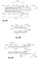
- FIG. 21 B illustrates one embodiment of a carrier member for the carrier assembly of FIG. 21 A .
- FIG. 21 C illustrates one embodiment of a pusher member for the carrier assembly of FIG. 21 A .
- FIG. 21 D illustrates one embodiment of a cover member for the carrier assembly of FIG. 21 A .
- FIG. 21 E illustrates one embodiment of a support member for the carrier assembly of FIG. 21 A .
- FIG. 22 A illustrates one embodiment of a carrier assembly for delivering a closure element.
- FIG. 22 B illustrates one embodiment of a carrier member for the carrier assembly of FIG. 22 A .
- FIG. 22 C illustrates one embodiment of a pusher member for the carrier assembly of FIG. 22 A .
- FIG. 22 D illustrates one embodiment of a cover member for the carrier assembly of FIG. 22 A .
- FIG. 22 E illustrates one embodiment of a support member having a splitter for the carrier assembly of FIG. 22 A .
- FIG. 23 A illustrates one embodiment of a carrier member.
- FIG. 23 B illustrates one embodiment of a pusher member.
- FIG. 24 A illustrates one embodiment of a carrier member.
- FIG. 24 B illustrates one embodiment of a pusher member.
- FIGS. 25 A- 25 D illustrate embodiments of splitters for use with a carrier assembly.
- FIG. 26 illustrates one embodiment of a splitter attached to a guide wire for use with a carrier assembly.
- FIGS. 27 A- 27 C illustrate embodiments of tissue-grabbing splitters for use with a carrier assembly.
- FIG. 28 illustrates an embodiment of a series of splitters configured to combine and expand for use with a carrier assembly.
- FIG. 29 A illustrates an embodiment of a selectively expandable splitter in a collapsed orientation.
- FIG. 29 B illustrates the selectively expandable splitter of FIG. 29 A in an expanded orientation.
- FIG. 30 A illustrates an embodiment of a selectively expandable splitter member in a collapsed orientation.
- FIG. 30 B illustrates the selectively expandable splitter member of FIG. 30 A in an expanded orientation.
- FIG. 31 A illustrates one embodiment of a carrier assembly having a slidable splitter that is splitting tubular members for delivering a closure element into an opening formed in a wall of a blood vessel.
- FIG. 31 B illustrates the closure element of FIG. 31 A being deployed over the splitter so as to be capable of engaging tissue adjacent to the opening in the blood vessel wall.
- FIG. 32 A is a cross-sectional side view illustrating an opening formed in a vessel, wherein a guidewire coupled with an embodiment of a tissue-grabbing splitter is shown disposed within the opening.
- FIG. 32 B illustrates the guidewire coupled with the tissue-grabbing splitter of FIG. 32 A , wherein the splitter is shown to be grabbing tissue disposed around the opening.
- FIG. 32 C illustrates an embodiment of a carrier assembly having a guide wire coupled with the tissue-grabbing splitter that is splitting tubular members for delivering a closure element over the splitter so as to be capable of engaging tissue adjacent to the opening in the blood vessel wall.
- FIG. 32 D illustrates the closure element of FIG. 32 C drawing the engaged tissue substantially closed and/or sealed.
- FIG. 33 A is an orthogonal cross-sectional profile of a closure element in a relaxed configuration.
- FIG. 33 B is a side view of the closure element of FIG. 33 A .
- FIG. 34 A is an orthogonal cross-sectional profile of the closure element of FIG. 33 A in a deploying configuration.
- FIG. 34 B is a longitudinal cross-sectional profile of the closure element of FIG. 33 A in the deploying configuration.
- FIG. 35 A is an orthogonal cross-sectional profile of the closure element of FIG. 33 A in a retaining configuration.
- FIG. 35 B is a longitudinal cross-sectional profile of the closure element of FIG. 33 A in the retaining configuration.
- FIG. 36 A is a schematic representation of a closure element decreasing when being stretched from the deploying configuration of FIGS. 34 A- 34 B to the retaining configuration of FIGS. 35 A- 35 B .
- FIG. 36 B is a schematic representation of a closure element changing from generally circular to generally oval when being stretched from the deploying configuration of FIGS. 34 A- 34 B to the retaining configuration of FIGS. 35 A- 35 B .
- FIGS. 37 A- 37 D illustrate other clip configurations according to the present invention.
- FIG. 38 A illustrates one embodiment of a carrier assembly having tubular members for retaining and delivering a closure element.
- FIG. 38 B illustrates one embodiment of an offset carrier member for the carrier assembly of FIG. 38 A .
- FIG. 38 C illustrates one embodiment of a closure element in an offset retaining configuration when retained by the carrier assembly of FIG. 38 A .
- FIG. 38 D illustrates one embodiment of an offset pusher member for the carrier assembly of FIG. 38 A .
- FIG. 38 E illustrates one embodiment of a cover member for the carrier assembly of FIG. 38 A .
- FIG. 38 F illustrates one embodiment of a support member for the carrier assembly of FIG. 38 A .
- FIG. 39 A illustrates one embodiment of a selectively expandable member in a collapsed orientation for retaining a closure element.
- FIG. 39 B illustrates one embodiment of a selectively expandable member in a selectively expanded orientation for deploying a closure element.
- FIG. 40 A illustrates one embodiment of a selectively expandable carrier tube in a collapsed orientation for retaining a closure element.
- FIG. 40 B illustrates one embodiment of a selectively expandable tube in a selectively expanded orientation for deploying a closure element.
- FIG. 40 C illustrates one embodiment of a selectively expandable tube in a selectively expanded orientation for deploying a closure element.
- FIG. 41 A illustrates one embodiment of a carrier assembly having an expandable member for delivering a closure element.
- FIG. 41 B illustrates one embodiment of a selectively expandable carrier member for the carrier assembly of FIG. 41 A .
- FIG. 41 C illustrates one embodiment of a closure element in an offset retaining configuration when held by the carrier assembly of FIG. 41 A .
- FIG. 41 D illustrates one embodiment of an offset pusher member for the carrier assembly of FIG. 41 A .
- FIG. 41 E illustrates one embodiment of a cover member for the carrier assembly of FIG. 41 A .
- FIG. 41 F illustrates one embodiment of a support member for the carrier assembly of FIG. 41 A .
- FIG. 42 A is a cross-sectional side view illustrating an opening formed in a vessel, wherein a guidewire is shown disposed within the opening.
- FIG. 42 B illustrates the guidewire being used to deploy a locator through the opening and locating the position of the vessel.
- FIG. 42 C illustrates an embodiment of a carrier assembly having offset tubular members for delivering a closure element in an offset retaining configuration so as to be capable of engaging tissue adjacent to the opening in the blood vessel wall.
- FIG. 42 D illustrates an embodiment of the closure element in a deploying configuration while being deployed from the carrier assembly.
- FIG. 42 E illustrates an embodiment of the closure element on a relaxed planar configuration after being deployed from the carrier assembly.
- FIG. 43 A is a cross-sectional side view illustrating a carrier assembly retaining a closure element in an offset retaining configuration and having a selectively expandable member in contracted orientation.
- FIG. 43 B is a cross-sectional side view illustrating a carrier assembly retaining a closure element in an offset retaining configuration and having a selectively expandable member in an expanded orientation and being positioned for deploying the closure element into tissue around an opening in the tissue.
- FIG. 43 C illustrates an embodiment of the closure element in a retaining configuration being deployed over the expanded expandable member.
- FIG. 43 D illustrates an embodiment of the closure element being deployed from the expanded expandable member so as to engage the tissue surrounding the opening.
- FIG. 44 provides a general illustration of an apparatus for closing openings formed in blood vessel walls constructed in accordance with the present invention.
- FIG. 45 illustrates one embodiment of a delivery assembly for the apparatus of FIG. 44 .
- FIG. 46 A illustrates a top view of one embodiment of a closure element in a natural, planar configuration and with a natural cross-section for use with the apparatus of FIG. 45 , prior to curing.
- FIG. 46 B illustrates a side view of the closure element of FIG. 46 A .
- FIG. 46 C illustrates a top view of the closure element of FIGS. 46 A- 46 B after a natural cross-section of the closure element has been reduced, via a curing process.
- FIG. 46 D illustrates a side view of the closure element of FIG. 46 C .
- FIG. 46 E illustrates a side view of the closure element of FIGS. 46 C- 46 D as the closure element transitions from the natural, planar configuration to a tubular configuration.
- FIG. 46 F illustrates a top view of the closure element of FIGS. 46 C- 46 D upon completing the transition from the natural, planar configuration to a substantially tubular configuration, albeit a natural tubular configuration.
- FIG. 46 G illustrates a side view of the closure element of FIG. 46 F .
- FIG. 47 A illustrates one embodiment of a distal locator portion and a carrier seat of a carrier assembly of FIG. 44 , both of which are illustrated in an unexpanded state.
- FIG. 47 B illustrates the distal locator portion and the carrier seat of FIG. 47 A , both of which are illustrated in an expanded state.
- FIG. 47 C illustrates one embodiment of a proximal end region of the delivery assembly of FIG. 44 .
- FIG. 48 A illustrates one embodiment of a carrier assembly for the apparatus of FIG. 44 .
- FIG. 48 B illustrates one embodiment of a pusher member for the carrier assembly of FIG. 48 A .
- FIG. 48 C illustrates one embodiment of a cover member for the carrier assembly of FIG. 48 A .
- FIG. 49 illustrates a tube set and the delivery assembly of the apparatus of FIG. 44 mounted to a handle portion for operative manipulation thereof.
- FIG. 50 A illustrates the closure element of FIGS. 46 A- 46 G prior to being disposed upon the carrier assembly of FIG. 48 A .
- FIG. 50 B illustrates the closure element of FIGS. 46 A- 46 G upon being disposed upon the carrier assembly of FIG. 48 A , and further as the cover member of FIG. 48 C receives the carrier assembly.
- FIG. 50 C illustrates the closure element of FIGS. 46 A- 46 G being retained substantially within the carrier assembly of FIG. 48 A when the carrier assembly is disposed substantially within the cover member of FIG. 48 C .
- FIG. 51 A illustrates a sheath that is positioned through tissue and into an opening formed in a wall of a blood vessel, in one embodiment of the present invention.
- FIG. 51 B illustrates the locator portion and the carrier assembly of the delivery assembly of the apparatus being advanced distally into the blood vessel.
- FIG. 51 C illustrates a distal end region of the locator portion of FIG. 51 B extending into the blood vessel and being transitioned into an expanded state.
- FIG. 51 D illustrates the distal end region of the locator portion of FIG. 51 C being retracted proximally to engage an inner surface of the blood vessel wall, and the retraction of the sheath to expose the tissue engaging device, in a tissue engaging condition.
- FIG. 51 E illustrates engagement of the tissue engaging device of the apparatus of FIG. 51 D with the blood vessel wall.
- FIG. 51 F illustrates movement of the tissue engaging device from the tissue engaging condition to a closing condition.
- FIG. 51 G illustrates the closure element being deployed and engaging tissue adjacent to the opening in the blood vessel wall.
- FIG. 51 H illustrates the closure element of FIG. 51 G transitioning from the substantially tubular configuration to the natural, planar configuration while engaging the engaged tissue.
- FIG. 52 is a side elevation view, in cross-section, of another embodiment of the clip applier apparatus having a tissue engaging device deployed from a central lumen of the tubular body, in a tissue engaging condition.
- FIG. 53 is a side elevation view, in cross-section, of the clip applier apparatus of FIG. 52 , illustrating the tissue engaging device in a closing condition.
- FIG. 54 is a side elevation view, in cross-section, of the clip applier apparatus of FIG. 52 , illustrating deployment of the closure element.
- FIG. 55 is a side elevation view, in cross-section, of yet another embodiment of the clip applier apparatus also having a tissue engaging device deployed from a central lumen of a tubular body, in a tissue engaging condition.
- FIG. 56 is a side elevation view, in cross-section, of the clip applier apparatus of FIG. 55 , illustrating the tissue engaging device in a closing condition.
- FIG. 57 is a side elevation view, in cross-section, of the clip applier apparatus of FIG. 55 , illustrating deployment of the closure element.
- FIG. 58 is a side elevation view, in cross-section, of another embodiment of the clip applier apparatus also having a tissue engaging device deployed from a central lumen of a tubular body, in a tissue closing condition.
- FIGS. 59 A- 59 E are partial cross-sectional views illustrating the luminal placement of a medical device for closing openings formed in blood vessel walls with improved hemostasis.
- FIGS. 60 A- 60 B are side views illustrating an embodiment of an expanding member for improving hemostasis during delivery of a closure device.
- FIGS. 61 A- 61 F are side views illustrating different embodiments of expanding members for improving hemostasis during delivery of a closure device.
- FIGS. 62 A- 62 B illustrate an anchor system in a collapsed configuration, and which can function as a locator.
- FIG. 63 illustrates an anchor system being deployed and expanded within a vessel.
- FIGS. 64 A- 64 B show an anchor being collapsed and withdrawn.
- FIGS. 65 A- 65 C show an implantable “looped” anchor system being used with a carrier assembly and tube set that deploys a blood vessel closure element.
- FIGS. 66 A- 66 B show an implantable coil anchor system being implanted with a closure element.
- FIGS. 67 A- 67 B show examples of removable or implantable anchors, which can be used as locators.
- FIG. 68 A shows an expanded hemostasis member and an implantable anchor cooperating to provide hemostasis.
- FIG. 68 B shows the unexpanded hemostasis member and an implantable anchor as a closure element is about to be deployed.
- inventions described herein extend to methods, systems, and apparatus for managing access through tissue.
- Some of the apparatuses of the present invention are configured to deliver a device for managing access through tissue into an opening formed in and/or adjacent to tissue.
- Embodiments are additionally directed to an apparatus and method for delivering a closure element through tissue and into an opening formed in, or adjacent to, a wall of a blood vessel or other body lumen of any size.
- the apparatus can be configured to receive and retain the closure element such that the closure element is disposed substantially within the apparatus. Thereby, if the apparatus is introduced via an introducer sheath, for example, the closure element can be disposed within, and delivered by way of, a lumen of the introducer sheath.
- the apparatus also is configured to engage the blood vessel wall adjacent to the opening and to position the closure element substantially adjacent to an outer surface of the blood vessel wall adjacent to the opening.
- the apparatus When properly positioned, the apparatus can be activated to distally deploy the closure element.
- the apparatus can be configured to substantially uniformly expand the closure element beyond a natural cross-section of the closure element such that the closure element, when deployed, is configured to engage a significant amount of the blood vessel wall and/or tissue.
- the closure element can be further configured to return to the natural cross-section. Thereby, the engaged blood vessel wall and/or tissue are drawn substantially closed and/or sealed, such that, for example, hemostasis within the opening is enhanced.
- an apparatus that is configured to prevent inadvertent tissue contact during positioning and to engage a substantial of amount of tissue adjacent to the opening can prove much more desirable and provide a basis for a wide range of medical applications, such as diagnostic and/or therapeutic procedures involving blood vessels or other body lumens of any size. This result can be achieved by employing a clip applier and associated methods of use in accordance with the present invention.
- Medical devices may be used in a variety of spaces. It may be desirable to generally reduce the size of medical devices. For example, stents may be inserted into smaller and smaller vasculature, thus making it generally desirable to reduce the pre-deployment size of a stent.
- a closure device may be used to close tissue in, for example, a body lumen. In order to reach the desired body lumen, typically a delivery device may be used to reach an access point in the body lumen. To minimize the effects of a procedure on a patient, the reduction in size of the access point may be desirable.
- a locator assembly When engaging tissue and/or closing openings in tissue, it may be desirable to use a locator assembly to selectably contact a portion of the tissue. In some cases, the locator assembly may not contact a portion of the desired tissue. For example, the locator assembly may be positioned within a body lumen but away from an inside surface of the body lumen. In these instances, engagement of a portion of the desired tissue may be less likely and/or favorable. It may be desirable to verify contact with a portion of the desired tissue during a medical procedure.
- a locator assembly may include engagement members configured to engage a portion of the desired tissue.
- the locator assembly may include a device to take measurements of a desired measurable characteristic.
- the measurable characteristic may include, for example, impedance. Measurements may be taken when a portion of the locator assembly is within a body lumen and when the locator assembly is believed to be in contact with tissue. Comparing the measurements taken when within the body lumen and when the locator assembly is believed to be in contact with tissue may indicate that the locator assembly has contacted a portion of the desired tissue. For example, an impedance measurement taken when within the body lumen may be higher than an impedance measurement taken when the locator assembly is in contact with tissue.
- a surface engaging element can be provided.
- the surface engaging element may include a flexible body that may actuate between an expanded and relaxed configuration.
- an engagement portion of the surface engaging element may include substantially uniform dimensions.
- the engagement portion of the surface engaging element may include at least one non-uniform dimension.
- the engagement portion may have a dimension that is larger than a support portion of the surface engaging element.
- the surface engaging element may be assembled using a retaining portion.
- an engagement portion may be connected to a proximal, distal, and/or other portion of the surface engaging element by a retaining portion, such as a detent.
- an apparatus that is configured to prevent inadvertent tissue contact during positioning and to engage a substantial of amount of tissue adjacent to the opening can prove much more desirable and provide a basis for a wide range of medical applications, such as diagnostic and/or therapeutic procedures involving blood vessels or other body lumens of any size. This result can be achieved, according to one embodiment of the present invention, by employing an apparatus 100 as shown in FIG. 1 .
- FIG. 1 illustrates a clip applier apparatus 100 in accordance with the present invention.
- the apparatus 100 can deliver a closure element 500 (shown in FIGS. 6 A- 6 B ) through tissue 630 (shown in FIG. 8 A ) and into an opening 610 (shown in FIG. 8 A ) formed in and/or adjacent to a wall 620 (shown in FIG. 8 A ) of a blood vessel 600 (shown in FIG. 8 A ) or other body lumen.
- the closure element (also referred to herein as a “clip”) 500 can have a generally annular-shapes body 510 (shown in FIGS.
- closure element 500 has a natural shape and size, the closure element 500 can be deformed into other shapes and sizes, as desired, and is configured to return to the natural shape and size when released.
- the closure element 500 can have a natural, planar configuration with opposing tines 520 and a natural cross-section 530 as shown in FIGS. 6 A- 6 B .
- the natural cross-section 530 of the closure element 500 can be reduced to form a reduced closure element 500 ′ that has a natural, planar configuration with opposing tines 520 and a reduced cross-section 530 ′ as shown in FIGS. 6 C- 6 D .
- the reduced closure element 500 ′ can be further deformed to form a substantially tubular closure element 500 ′′ (shown in FIG. 6 F ) having the reduced cross-section 530 ′ as well as being in a substantially tubular configuration with the tines 520 in an axial configuration.
- the closure element 500 can be formed from any suitable material, including any biodegradable material, any shape memory alloy, such as alloys of nickel-titanium, or any combination thereof. Additionally, it is contemplated that the closure element may be coated with a beneficial agent or be constructed as a composite, wherein one component of the composite would be a beneficial agent. As desired, the closure element 500 may further include radiopaque markers (not shown) or may be wholly or partially formed from a radiopaque material to facilitate observation of the closure element 500 using fluoroscopy or other imaging systems.
- Exemplary embodiments of a closure element are disclosed in U.S. Pat. Nos. 6,197,042, and 6,623,510, and in co-pending application Ser. Nos. 09/546,998, 09/610,238, and 10/081,726. The disclosures of these references and any others cited therein are expressly incorporated herein by reference.
- the apparatus 100 can be configured to receive and retain the closure element 500 such that the closure element 500 is disposed substantially within the apparatus 100 .
- the closure element 500 can be disposed within, and delivered by way of, a lumen 644 (shown in FIG. 8 A ) of the introducer sheath 640 .
- the apparatus 100 also can be configured to engage the blood vessel wall 620 adjacent to the opening 610 . Being disposed substantially within the apparatus 100 , the closure element 500 can deeply penetrate, without inadvertently contacting, tissue 630 adjacent to the opening 610 such that the apparatus 100 can position the closure element 500 substantially adjacent to an outer surface 620 a (shown in FIG. 8 A ) of the blood vessel wall 620 adjacent to the opening 610 .
- the apparatus 100 When properly positioned, the apparatus 100 can be activated to deploy the closure element 500 .
- the apparatus 100 can be configured to substantially uniformly expand the closure element 500 beyond the natural cross-section 530 of the closure element 500 during deployment, the apparatus 100 , as desired, and/or can deploy the closure element 500 without expanding the closure element 500 .
- the closure element 500 when deployed, can be configured to engage a significant amount of the blood vessel wall 620 and/or tissue 630 adjacent to the opening 610 . Engaging the blood vessel wall 620 and/or tissue 630 , the closure element 500 is further configured to return to the natural cross-section 530 .
- the engaged blood vessel wall 620 and/or tissue 630 can be drawn substantially closed and/or sealed, such that, for example, hemostasis within the opening 610 is enhanced.
- the apparatus 100 can be provided as one or more integrated components and/or discrete components. As shown in FIG. 1 , for example, the apparatus 100 can include a locator (or obturator) assembly 200 and a carrier assembly 300 . For purposes of illustration, the locator assembly 200 and the carrier assembly 300 are shown in FIG. 1 as including substantially separate assemblies. As desired, however, the locator assembly 200 and the carrier assembly 300 each can be provided, in whole or in part, as one or more integrated assemblies.
- the locator assembly 200 can selectably contact the inner surface 620 b of the blood vessel wall 620 adjacent the opening 610 . Whereby, the locator assembly 200 can be configured to draw the blood vessel wall 620 taut and maintain the proper position of the apparatus 100 in relation to the opening 610 as the blood vessel 600 pulsates.
- the locator assembly 200 can be provided in the manner disclosed in co-pending application Ser. Nos. 09/732,835 and 10/081,723, the disclosures of which are expressly incorporated herein by reference.
- the locator assembly 200 can include a flexible or semi-rigid tubular body 210 . As illustrated in FIG.
- the tubular body 210 has a proximal end region 210 a and a distal end region 210 b and includes a predetermined length 218 a and a predetermined outer cross-section 218 b , both of which can be of any suitable dimension.
- the distal end region 210 b of the locator assembly 200 can include a substantially rounded, soft, and/or flexible distal end or tip 220 to facilitate atraumatic advancement and/or retraction of the distal end region 210 b into the blood vessel 600 .
- a pigtail (not shown) may be provided on the distal end 220 to further aid atraumatic advancement of the distal end region 210 b.
- the distal end region 210 b of the locator assembly 200 further can be selectably controllable between an unexpanded state and an expanded state.
- the distal end region 210 b In the unexpanded state, the distal end region 210 b has an unexpanded size; whereas, the distal end region 210 b in the expanded state has an expanded size, which is greater than the unexpanded size of the distal end region 210 b in the unexpanded state.
- the distal end region 210 b can be configured to expand from the unexpanded size to the expanded size and/or to contract from the expanded size to the unexpanded size, and the expansion and contraction of the distal end region 210 b can be substantially uniform about a longitudinal axis of the locator assembly 200 .
- one or more expansion elements 230 can be provided on the distal end region 210 b and can be configured to expand substantially transversely with respect to a longitudinal axis of the locator assembly 200 .
- the expansion elements 230 can be substantially equally distributed about an outer periphery 212 of the distal end region 210 b .
- the expansion elements 230 may include radiopaque markers (not shown) or may be wholly or partially formed from a radiopaque material to facilitate observation of the expansion elements 230 and/or the distal end region 210 b using fluoroscopy or other imaging systems.
- At least one (and, at least in some cases, all) of the expansion elements 230 can include a substantially flexible member 230 ′ with a substantially fixed end region 230 a ′, an intermediate region 230 b ′, and a movable end region 230 c ′ as shown in FIGS. 2 B- 2 C .
- the fixed end region 230 a ′ can be fixedly coupled with the distal end region 210 b
- the movable end region 230 c ′ can be movably coupled with the distal end region 210 b and configured to be axially movable relative to the fixed end region 230 a ′.
- each movable end region 230 c ′ can be axially moved toward the relevant fixed end region 230 a ′, the intermediate regions 230 b ′ buckle and/or expand transversely outwardly, thereby transitioning the distal end region 210 b of the locator assembly 200 from the unexpanded state to the expanded state.
- the distal end region 210 b transitions from the expanded state to the unexpanded state as each of the movable end regions 230 c ′ are axially moved away from the relevant fixed end region 230 a ′.
- the expansion elements 230 are shown as including the flexible members 230 ′ in FIGS.
- the expansion elements 230 can include any type of expansion elements and are not limited to the illustrated embodiments. It is further contemplated that the expansion elements 230 may further include geometric features that allow/enhance the ability of the expansion elements to bend or fold from a retracted position to an expanded position.
- the expansion elements may be constructed of a material such as steel, spring steel, plastics or composites. In one embodiment, the expansion elements are constructed of Nitinol®.
- FIGS. 2 B ′ and 2 C′ illustrate an alternative embodiment of a locator assembly 200 ′′ for locating a surface of a body lumen, in accordance with the present invention.
- the locator assembly 200 ′′ of this embodiment may be functionally similar to that of the locator assembly 200 previously described above and shown in FIGS. 2 B and 2 C in most respects, wherein certain features will not be described in relation to this embodiment wherein those components may function in the manner as described above and are hereby incorporated into this alternative embodiment described below.
- Like structures and/or components are given like reference numerals.
- the locator assembly 200 ′′ may be located proximal to a distal end 210 b ′′ of a tubular member 210 ′′ and/or an apparatus (such as apparatus 100 shown in FIG. 1 ).
- the locator assembly 200 ′′ may include a surface engagement assembly 226 ′′.
- the surface engagement assembly 226 ′′ may include a distal end portion 226 a ′′, a proximal end portion 226 b ′′, and/or at least one surface engagement element 230 ′′.
- the surface engagement elements 230 ′′ may be configured to transition from a relaxed state to an expanded state, similar to the substantially flexible member 230 ′ described above.
- the surface engagement elements 230 ′′ may be movably connected to and/or fixedly connected to a distal end region 210 b ′′ of the locator assembly 200 ′′.
- a distal end 230 a ′′ of the surface engagement elements 230 ′′ may be movably connected to a proximal end 230 c ′′ of the surface engagement elements 230 ′′ may be fixedly connected to the distal end region 210 b ′′.
- other types of connections may be contemplated.
- the locator assembly 200 ′′ may include two, three, four, and/or other numbers of surface engaging elements 230 ′′. At least one of the surface engaging elements 230 ′′ may be configured to conduct a measurable characteristic of the surface engaging elements 230 ′′ to the locator assembly 200 ′′.
- the locator assembly 200 ′′ may be in communication with a measuring device 251 .
- An example of a measuring device 251 may include an impedance measuring device, a volt meter, an amp meter, a pressure transducer, piezoelectric crystals, other measuring devices, or combinations thereof.
- the measuring device 251 may determine changes in measurable characteristics of the locator assembly 200 ′′. For instance, the measuring device 251 may measure changes in the impedance of the locator assembly 200 ′′.
- the measuring device 251 may determine changes in pressure. Changes in pressure may be determined by a pressure transducer or other pressure measuring device.
- the measuring device 251 may retrieve ultrasonic data in and/or around the body lumen. Ultrasonic data may be retrieved by piezoelectric crystal or other ultrasonic data gathering device. Other measurable characteristics may include electrical characteristics such as voltage, current, other electrical characteristics, and/or other measurable characteristics.
- the locator assembly 200 ′′ may be in electrical communication with at least one of the surface engaging elements 230 ′′.
- the locator assembly 200 ′′ may include at least one distal conductive portion 204 a ′′ and/or at least one proximal conductive portion 204 b ′′ with which at least one surface engaging element 230 ′′ may be in electrical communication.
- At least one of surface engaging elements 230 ′′ may be formed at least partially from an electrically conductive material.
- at least one of surface engaging elements 230 ′′ may be formed at least partially from Nitinol®.
- the distal conductive portions 204 a ′′ and/or the proximal conductive portions 204 b ′′ may be in electrical communication with the measuring device 251 .
- the at least one distal conductive portion 204 a ′′ may be in electrical communication with the measuring device 251 through at least one distal conductor connector 205 a ′′ and/or the at least one proximal conductive portion 204 b ′′ may be in electrical communication with the measuring device 251 through at least one proximal conductor connector 205 b ′′.
- the distal and/or proximal conductor connectors 205 a ′′, 205 b ′′ may extend toward the distal end 210 b ′′ and/or toward a proximal end 210 a ′′ of the tubular member 210 ′′ through at least one lumen (not shown).
- each of the surface engaging elements 230 ′′ may be in electrical communication with a different distal conductive portion 204 a ′′ and/or proximal conductive portion 204 b ′′.
- more than one surface engaging element 230 ′′ may be in electrical communication with the same distal conductive portion 204 a ′′ and/or proximal conductive portion 204 b ′′.
- Other combinations are also contemplated.
- the surface engaging elements 230 ′′ may be in electrical communication with each other.
- two or more surface engaging elements 230 ′′ may be may be formed from the same piece of material.
- each of the surface engaging elements 230 ′′ may be selectively electrically isolated from each other. Isolation of the surface engaging elements 230 ′′ may be accomplished by insulators 206 a ′′, 206 b ′′.
- the insulators 206 a ′′, 206 b ′′ may include materials such as ceramics, polyethylene, and/or other insulating materials.
- FIGS. 2 B ′′ and 2 C′′ illustrate a further embodiment of a locator assembly 200 ′′′′ for locating a surface of a body lumen, in accordance with the present invention.
- the locator assembly 200 ′′′ of this embodiment may be functionally similar to that of the locator assemblies 200 , 200 ′′ previously described above and shown in FIGS. 2 B- 2 C and 2 B ′- 2 C′ in most respects, wherein certain features will not be described in relation to this embodiment wherein those components may function in the manner as described above and are hereby incorporated into this alternative embodiment described below.
- Like structures and/or components are given like reference numerals.
- the locator assembly 200 ′′′ may be configured to facilitate the determination of changes in measurable characteristics of the locator assembly.
- the locator assembly 200 ′′′ may be located proximal to a distal end of a tubular member (such as 210 b , 210 b ′′ shown in FIGS. 2 A, 2 B, 2 A ′, and 2 B′) and/or an apparatus (such as apparatus 100 shown in FIG. 1 ).
- the locator assembly 200 ′′′ may include a surface engagement assembly 226 ′′′.
- the surface engagement assembly 226 ′′′ may include a distal end portion 226 a ′′′, a proximal end portion 226 b ′′′, and/or at least one surface engagement element 230 ′′′.
- the surface engagement assembly 226 ′′′ may include four surface engagement elements 230 ′′′ that may be separated by a distal and/or proximal engagement element support 231 a ′′′, 231 b ′′′.
- the distal and/or proximal engagement element supports 231 a ′′′, 231 b ′′′ may electrically insulate the surface engagement elements 230 ′′′.
- the distal engagement element supports 231 a ′′′, proximal engagement element supports 231 b ′′′, and/or surface engagement elements 230 ′′′ may be formed as a unitary piece and/or from the same material.
- the distal engagement element supports 231 a ′′′, proximal engagement element supports 231 b ′′′, and/or surface engagement elements 230 ′′′ may be laser cut from a Nitinol® tube.
- the surface engagement elements 230 ′′′ may include a distal and/or proximal retaining portion 229 a ′′′, 229 b ′′′.
- the distal and/or proximal retaining portions 229 a ′′′, 229 b ′′′ may include an aperture and/or other retaining mechanism that may receive, for example, a detent and/or other retaining mechanism.
- a cover member (such as the cover member 220 shown in FIG. 2 C ) may include a retaining mechanism (not shown) to limit motion between the cover member and the surface engagement elements 230 ′′′.
- the cover member may be connected to a control member (such as control member 250 shown in FIG. 2 D ) that is configured to transition the surface engagement elements 230 ′′′ from a relaxed state to an expanded state, similar to the substantially flexible member 230 ′ described above.
- the surface engaging elements 230 ′′′ may include a measuring component 253 ′′′.
- the measuring component 253 ′′′ may facilitate the determination of changes in measurable characteristics of the locator assembly 200 ′′′.
- the measuring component 253 ′′′ may facilitate the determination of changes in impedance, pressure, ultrasonic data, or other measurable characteristics.
- the measuring component 253 ′′′ may be in electrical communication with a connector 205 ′′′.
- the connector 205 ′′′ may be in electrical communication with a measuring device (shown as 251 in FIG. 2 B ′).
- FIGS. 2 B ′′′ and 2 C′′′ illustrate a further embodiment of a locator assembly 200 ′′′′ for locating a surface of a body lumen, in accordance with the present invention.
- the locator assembly 200 ′′′′ of this embodiment may be functionally similar to that of the locator assemblies 200 , 200 ′, 200 ′′, 200 ′′′ previously described above and shown in FIGS. 2 B- 2 C, 2 B ′- 2 C′, and 2 B′′- 2 C′′ in most respects, wherein certain features will not be described in relation to this embodiment wherein those components may function in the manner as described above and are hereby incorporated into this alternative embodiment described below.
- Like structures and/or components are given like reference numerals.
- the locator assembly 200 ′′′′ may be located proximal to a distal end of a tubular member (such as 210 b , 210 b ′′ shown in FIGS. 2 A, 2 B, 2 A ′, and 2 B′) and/or an apparatus (such as apparatus 100 shown in FIG. 1 ).
- the locator assembly 200 ′′′′ may include a surface engagement assembly 226 ′′′′, a cover member 220 ′′′′, and/or a proximal end portion 226 b′′′′.
- the cover member 220 ′′′′ and/or proximal end portion 226 b ′′′′ may include a distal retaining portion 221 a ′′′′ and/or a proximal retaining portion 221 b ′′′′, respectively.
- the surface engagement assembly 226 ′′′′ may include at least one surface engagement element 230 ′′′′.
- the surface engagement elements 230 ′′′′ may include a distal and/or proximal retaining portion 229 a ′′′′, 229 b ′′′′.
- the distal and/or proximal retaining portions 221 a ′′′′, 221 b ′′′′ on the cover member 220 ′′′′ and/or proximal end portion 226 b ′′′′ may include an aperture and/or other retaining mechanism that may cooperate with corresponding distal and/or proximal retaining portions 229 a ′′′′, 229 b ′′′′, such as a detent and/or other retaining mechanism, on the surface engagement elements 230 ′′′′ to limit motion between the cover member 220 ′′′′, the proximal end portion 226 b ′′′′, and/or the surface engagement elements 230 ′′′′.
- the distal and/or proximal retaining portions 229 a ′′′′, 229 b ′′′′ may be located near a distal and/or proximal end 230 a ′′′′, 230 b ′′′′ of the surface engagement element 230 ′′′′, respectively.
- a control member 250 ′′′′ may be inserted through the proximal end portion 226 b ′′′′ and/or may be connected to the cover member 220 ′′′′.
- the control member 250 ′′′′ may be used to transition the surface engagement elements 230 ′′′′ from a relaxed state to an expanded state, similar to the substantially flexible member 230 ′ described above.
- control member 250 ′′′′ may be a single piece, which may be elongate from the cover member 220 ′′′′ toward a proximal end (such as proximal end 210 a ′′ shown in FIG. 2 B ′) of the locator assembly 200 ′′′′.
- control member 250 ′′′′ may be in one or more pieces that may be connected together using various mechanisms, similar to the retaining portions 221 a ′′′′, 221 b ′′′′, 229 a ′′′′, 229 b ′′′′ described above.
- the proximal end portion 226 b ′′′′ may include a tubular member retaining portion 228 ′′′′.
- the tubular member retaining portion 228 ′′′′ may be configured to engage a distal end (such as distal end 210 b , 210 b ′′ shown in FIGS. 2 B and 2 B ′).
- the tubular member retaining portion 228 ′′′′ in the present embodiment, may include a ramp and/or other retaining mechanism to limit the motion of the tubular member in at least one direction.
- the surface engagement elements 230 ′′′′ may include an engagement member 232 ′′′′.
- the engagement member 232 ′′′′ may include an engagement portion 234 ′′′′ and/or an engagement support portion 237 ′′′′.
- the engagement portion 234 ′′′′ may be configured to contact and/or engage tissue.
- the engagement portion 234 ′′′′ in the present embodiment, may be enlarged in an intermediate portion 235 ′′′′ in comparison to distal and/or proximal end 234 a ′′′′, 234 b ′′′′ of the engagement portion 234 ′′′′.
- An enlarged intermediate portion 235 ′′′′ may facilitate contact and/or engagement with tissue.
- the engagement support portion 237 ′′′′ may support the engagement portion 234 ′′′′ during, for example, transitioning from a relaxed state to an expanded state.
- the engagement support portion 237 ′′′′ may include an enlarged intermediate portion 238 ′′′′, similar to the enlarged intermediate portion 235 ′′′′ of the engagement portion 234 ′′′′. Having an enlarged intermediate portion 238 ′′′′ on the engagement support portion 237 ′′′′ may add stability to the engagement portion 234 ′′′′ while in the expanded state.
- the intermediate portions 235 ′′′′, 238 ′′′′ of the engagement portions 234 ′′′′ and/or the engagement support portions 237 ′′′′ may be oval shaped.
- the intermediate portions 235 ′′′′, 238 ′′′′ may have the same shape, have differing shapes, and/or have other combinations of shapes.
- the proximal end 234 b ′′′′ of the engagement portion 234 ′′′′ may be connected to a proximal support portion 233 ′′′′.
- the proximal support portion 233 ′′′′ may be connected to the proximal end portion 226 b ′′′′ and may separate the engagement portion 234 ′′′′ from the proximal end portion 226 b ′′′′.
- the distal end 234 a ′′′′ of the engagement portion 234 ′′′′ may be connected to an intermediate support portion 236 ′′′′.
- the intermediate support portion 236 ′′′′ may be connected to the proximal end 237 b ′′′′ of the engagement support portion 237 ′′′′ and may separate the engagement portion 234 ′′′′ from the engagement support portion 237 ′′′′.
- the distal end 237 a ′′′′ of the engagement support portion 237 ′′′′ may be connected to a distal support portion 239 ′′′′.
- the distal support portion 239 ′′′′ may be connected to the distal end (not shown) of the surface engagement element 230 ′′′′ and may separate the engagement support portion 237 ′′′′ from the distal end portion 226 a′′′′.
- the surface engaging elements 230 ′′′′ may include a measuring component 253 ′′′′.
- the measuring component 253 ′′′′ may facilitate the determination of changes in measurable characteristics of the locator assembly 200 ′′′′.
- the measuring component 253 ′′′′ may facilitate the determination of changes in impedance, pressure, ultrasonic data, or other measurable characteristics.
- the measuring component 253 ′′′′ may be in electrical communication with a connector 205 ′′′′.
- the connector 205 ′′′′ may be in electrical communication with a measuring device (shown as 251 in FIG. 2 B ′).
- the locator assembly 200 may further include a locator control system associated with the locator assembly.
- the locator control system 240 can be associated with the proximal end region 210 a of the locator assembly 200 and can be configured to selectively control the distal end region 210 b of the locator assembly 200 between the unexpanded and expanded states.
- the locator control system 240 can selectively control the distal end region 210 b between the unexpanded and expanded states, such as by being activated by a switching system (not shown).
- a control member 250 such as a rod, wire, or other elongate member, can be movably disposed within a lumen (not shown) formed by the tubular body 210 and extending substantially between the proximal end region 210 a and the distal end region 210 b .
- the control member 250 has a proximal end region 250 a that is coupled with the locator control system 240 , which can be via a control block 260 (shown in FIG. 4 D ), and a distal end region (not shown) that is coupled with the distal end region 210 b of the locator assembly 200 , the expansion elements 230 , and/or the movable end regions 230 c ′ of the substantially flexible members 230 ′.
- the locator control system 240 can selectively transition the distal end region 210 b , the expansion elements 230 , and/or the substantially flexible members 230 ′ between the unexpanded and expanded states by moving the control member 250 axially relative to the tubular body 210 .
- the locator control system 240 further includes a locator release system 490 for maintaining the unexpanded state and/or the expanded state of the distal end region 210 b , the expansion elements 230 , and/or the substantially flexible members 230 ′.
- the locator release system 490 can be configured to maintain the expanded state of the distal end region 210 b , and can include any type of locking system and can be engaged, for instance, by activating the switching system. For example, once the substantially flexible members 230 ′ have entered the expanded state, the locator release system 490 can secure the control member 250 to prevent axial movement relative to the tubular body 210 , thereby maintaining the substantially flexible members 230 ′ in the expanded state.
- the locator control system 240 also can be configured to disengage the locator release system 490 , such that the distal end region 210 b , the expansion elements 230 , and/or the substantially flexible members 230 ′ can transition between the expanded and unexpanded states.
- the locator release system 490 can be disengaged, for example, by activating an emergency release system (not shown).
- the locator control system 240 may further include a biasing system (not shown), such as one or more springs or other resilient members, to bias the distal end region 210 b , the expansion elements 230 , and/or the substantially flexible members 230 ′ to enter and/or maintain the unexpanded state when the locator release system 490 is disengaged.
- a biasing system such as one or more springs or other resilient members, to bias the distal end region 210 b , the expansion elements 230 , and/or the substantially flexible members 230 ′ to enter and/or maintain the unexpanded state when the locator release system 490 is disengaged.
- the carrier assembly 300 can be coupled with, and slidable relative to, the locator assembly 200 .
- the carrier assembly 300 is configured to receive and retain the closure element 500 (shown in FIGS. 6 A- 6 B ), which can be disposed substantially within the carrier assembly 300 .
- the locator assembly 200 engages the inner surface 620 b (shown in FIG. 8 A ) of the blood vessel wall 620 (shown in FIG. 8 A )
- the carrier assembly 300 can be further configured to position the closure element 500 substantially adjacent to the opening 610 (shown in FIG. 8 A ) and to deploy the closure element 500 .
- the closure element 500 Upon being deployed, the closure element 500 can maintain the reduced cross-section 530 ′ (shown in FIGS.
- the closure element 500 when deployed, can engage a significant amount of the blood vessel wall 620 and/or tissue 630 adjacent to the opening 610 . Thereafter, the closure element 500 can be configured to return to the natural cross-section 530 such that the blood vessel wall 620 and/or tissue 630 is drawn substantially closed and/or sealed.
- the carrier assembly 300 can include a tube set 305 , including a carrier member 310 , a pusher member 320 , a support tube 340 , and a cover member 330 .
- the carrier member 310 , the pusher member 320 , the support tube 340 , and the cover member 330 can be provided as a plurality of nested, telescoping members with a common longitudinal axis 350 as illustrated in FIG. 3 A .
- the carrier member 310 can be configured to receive and support the closure element 500 . While being disposed on the carrier member 310 , the closure element 500 can be deformed from the natural, planar configuration to form the substantially tubular closure element 500 ′′ (shown in FIGS.
- the substantially tubular closure element 500 ′′ Being disposed substantially about, and supported by, an outer periphery 312 b of the carrier member 310 , the substantially tubular closure element 500 ′′ can be substantially in axial alignment with the carrier member 310 with the tines 520 pointed substantially distally.
- the carrier member 310 can be formed as a substantially rigid, semi-rigid, or flexible tubular member. Additionally, the carrier member 310 can have a proximal end region 310 a and a distal end region 310 b and includes a predetermined length 318 a and a predetermined cross-section 318 b , both of which can be of any suitable dimension. The carrier member 310 also can define a lumen 314 that extends substantially between the proximal end region 310 a and the distal end region 310 b and that is configured to slidably receive at least a portion of the tubular body 210 of the locator assembly 200 .
- the distal end region 310 b of the carrier member 310 can have a cross-section that increases distally, as illustrated in FIGS. 3 A- 3 B , for substantially uniformly expanding the substantially tubular closure element 500 ′′ beyond the natural cross-section 530 of the closure element 500 when the substantially tubular closure element 500 ′′ is deployed.
- the distal end region 310 b can be formed with a cross-section (not shown) that is substantially uniform.
- the distal end region 310 b of the carrier member 310 can be provided with the substantially-uniform cross-section and that the substantially tubular closure element 500 ′′ can be deployed without being expanded.
- the pusher member 320 Being configured to distally deploy the substantially tubular closure element 500 ′′, the pusher member 320 has a proximal end region 320 a and a distal end region 320 b and is coupled with, and slidable relative to, the carrier member 310 .
- the pusher member 320 includes a predetermined length 328 a and a predetermined cross-section 328 b , both of which can be of any suitable dimension and can be configured to slidably receive the carrier member 310 such that the distal end region 320 b of the pusher member 320 is offset proximally from the distal end region 310 b of the carrier member 310 .
- the predetermined length 328 a of the pusher member 320 can be greater than or substantially equal to the predetermined length 318 a of the carrier member 310 .
- the predetermined length 328 a of the pusher member 320 can be less than the predetermined length 318 a of the carrier member 310 such that the carrier member 310 and the pusher member 320 at least partially define a space 360 distal to the distal end region 320 b of the pusher member 320 and along the periphery 312 b of the carrier member 310 .
- the pusher member 320 can be substantially tubular and can define a lumen 324 that extends substantially between the proximal end region 320 a and the distal end region 320 b and that is configured to slidably receive at least a portion of the carrier member 310 .
- the cross-section 328 b of the pusher member 320 can be substantially uniform, and the distal end region 320 b of the pusher member 320 can include one or more longitudinal extensions 325 , which extend distally from the pusher member 320 and along the periphery 312 b of the carrier member 310 as shown in FIG. 3 C .
- the longitudinal extensions 325 can be biased such that the longitudinal extensions 325 extend generally in parallel with common longitudinal axis 350 .
- the longitudinal extensions 325 are sufficiently flexible to expand radially, and yet sufficiently rigid to inhibit buckling, as the distal end region 320 b is directed distally along the carrier member 310 , and to engage the distally-increasing cross-section of the distal end region 310 b of the carrier member 310 to deploy the substantially tubular closure element 500 ′′.
- a cover member 330 is configured to retain the substantially tubular closure element 500 ′′ substantially within the carrier assembly 300 prior to deployment as shown in FIG. 3 D . Being coupled with, and slidable relative to, the pusher member 320 , the cover member 330 has a proximal end region 330 a and a distal end region 330 b and includes a predetermined length 338 a and a predetermined cross-section 338 b , both of which can be of any suitable dimension.
- the cover member 330 can be formed as a substantially rigid, semi-rigid, or flexible tubular member. Additionally, the cover member 330 can have an inner periphery 332 a and an outer periphery 332 b and can define a lumen 334 .
- the lumen 334 can extend substantially between the proximal and distal end regions 330 a , 330 b of the cover member 330 and can be configured to slidably receive at least a portion of the pusher member 320 .
- the distal end region 330 b can be configured to extend over the space 360 , thereby defining an annular cavity 370 for receiving and retaining the substantially tubular closure element 500 ′′.
- the cross-section 338 b of the cover member 330 can be substantially uniform, and the distal end region 330 b of the cover member 330 can include one or more longitudinal extensions 335 , which extends distally from the cover member 330 and along an outer periphery 322 b of the pusher member 320 as shown in FIG. 3 D .
- the longitudinal extensions 335 can extend generally in parallel with common longitudinal axis 350 , the longitudinal extensions 335 can be biased such that the plurality of longitudinal extensions 335 extends substantially radially inwardly as illustrated in FIGS. 3 A and 3 D .
- the longitudinal extensions 335 can at least partially close the lumen 334 substantially adjacent to the distal end region 330 b of the cover member 330 .
- the longitudinal extensions 335 can be sufficiently flexible to expand radially to permit the distal end region 310 b of the carrier member 310 to move distally past the cover member 330 to open the annular cavity 370 such that the distal end region 330 b no longer extends over the space 360 .
- the carrier member 310 can be at least partially disposed within, and slidable relative to, the lumen 324 of the pusher member 320 as shown in FIG. 3 C .
- the pusher member 320 in turn, can be at least partially disposed within, and slidable relative to, the lumen 334 of the cover member 330 .
- the tubular body 210 of the locator assembly 200 can be at least partially disposed within, and slidable relative to, the lumen 314 of the carrier member 310 .
- the longitudinal axis of the locator assembly 200 can be substantially in axial alignment with the common longitudinal axis 350 of the carrier member 310 , the pusher member 320 , the cover member 330 , and the support tube 340 .
- the tube set 305 can also include a support member 340 as shown in FIGS. 3 A and 3 E .
- the support member 340 is configured to slidably receive the tubular body 210 of the locator assembly 200 and to provide radial support for the distal end region 210 b of the tubular body 210 when the locator assembly 200 is coupled with the carrier assembly 300 .
- the carrier assembly 300 can advantageously include the support member 340 , for example, if the tubular body 210 is not sufficiently rigid or under other circumstances in which support for the tubular body 210 might be desirable.
- the support member 340 also can be configured to inhibit the plurality of longitudinal extensions 335 , which extend from the distal end region 330 b of the cover member 330 , from expanding prematurely prior to the closure element 500 being deployed.
- the support member 340 can be formed as a substantially rigid, semi-rigid, or flexible tubular member, having a proximal end region 340 a and a distal end region 340 b . Wherein an outer periphery 342 b of the support member 340 can define a lumen 344 that extends substantially between the proximal end region 340 a and the distal end region 340 b , the lumen is configured to slidably receive and support at least a portion of the tubular body 210 of the locator assembly 200 .
- the support member 340 in turn, can be at least partially slidably disposed within the lumen 314 of the carrier member 310 such that the tubular body 210 of the locator assembly 200 may be coupled with, and slidable relative to, the carrier member 310 in the manner described in more detail above.
- the support member 340 can have a predetermined length 348 a and a predetermined cross-section 348 b , both of which can be of any suitable dimension, and the cross-section 348 b can be substantially uniform.
- the carrier member 310 , the pusher member 320 , the cover member 330 , and/or the support member 340 can be provided, in whole or in part, as one or more integrated assemblies.
- the carrier assembly 300 may further include a housing 380 as illustrated in FIG. 4 A .
- the housing 380 can be formed as an elongate member with a longitudinal axis 386 . Additionally, the housing 380 can have an outer periphery 382 b and includes a proximal end region 380 a and a distal end region 380 b .
- the tubular body 210 of the locator assembly 200 at least partially disposed within the tube set 305 such that the distal end region 210 b of the tubular body 210 extends beyond the distal end regions 310 b , 320 b , 330 b , and/or 340 b .
- the tubular body 210 , the carrier member 310 , the pusher member 320 , the cover member 330 , and, if provided, the support member 340 can be at least partially disposed within, and slidable relative to, the housing 380 , and the respective distal end regions 210 b , 310 b , 320 b , 330 b , and 340 b extend from the distal end region 380 b of the housing 380 such that the common longitudinal axis 350 (shown in FIG. 3 A ) of the tube set 305 is substantially axially aligned with the longitudinal axis 386 of the housing 380 .
- the housing 380 supports the tube set 305 and can have one or more handles 390 to facilitate use of the apparatus 100 .
- the handles 390 extend substantially radially from the outer periphery 382 b of the housing 380 and can be provided in the manner known in the art.
- the tubular body 210 of the locator assembly 200 can be at least partially disposed within the tube set 305 of the carrier assembly 300 such that the distal end region 210 b of the tubular body 210 extends beyond the distal end regions 310 b , 320 b , 330 b , and/or 340 b .
- the proximal end region 210 a of the tubular body 210 and the proximal end regions 310 a , 320 a , 330 a , and/or 340 a of the tube set 305 are at least partially disposed within, and slidable relative to, the housing 380 .
- the switching system of the locator assembly 200 and a switching system 450 of the triggering system 400 can be accessible external to the housing 380 as shown in FIGS. 4 A and 4 C .
- a triggering system 400 can be disposed substantially within the housing 380 .
- the triggering system 400 can be configured to control the relative axial movement and/or positioning of the respective distal end regions 310 b , 320 b , 330 b , and 340 b of the tube set 305 and/or the distal end region 210 b of the locator assembly 200 .
- the triggering system 400 can control the relative axial movement of the distal end regions 210 b , 310 b , 320 b , 330 b , and/or 340 b in any manner, such as by being activated by the switching system 450 .
- the triggering system 400 can induce axial motion, such as distal motion, with respect to one or more of the distal end regions 210 b , 310 b , 320 b , 330 b , and/or 340 b .
- One or more of the distal end regions 210 b , 310 b , 320 b , 330 b , and/or 340 b can be axially moved.
- Axial motion of one or more of the carrier member 310 , the pusher member 320 , the cover member 330 , and the support member 340 and/or the tubular body 210 can be attained, for example, by applying an axial force to the switching system 450 .
- one or more of the distal end regions 210 b , 310 b , 320 b , 330 b , and/or 340 b may include radiopaque markers (not shown) or may be wholly or partially formed from a radiopaque material.
- the triggering system 400 can be configured to overcome internal resistance such that the relative axial movement and/or positioning of the respective distal end regions 310 b , 320 b , 330 b , and 340 b of the tube set 305 and/or the distal end region 210 b of the locator assembly 200 are controlled in accordance with a predetermined manner when the triggering system 400 is activated. Thereby, movement and/or positioning of the distal end regions 310 b , 320 b , 330 b , 340 b , and/or 210 b can be initiated when at least a predetermined quantity of force is applied to the switching system 450 .
- a force that is less than the predetermined quantity generally may be insufficient to activate the triggering system 400 ; whereas, when the force increases to a level that is greater than or substantially equal to the predetermined quantity, the triggering system 400 is configured to activate, move and/or position the distal end regions 310 b , 320 b , 330 b , 340 b , and/or 210 b in accordance with the predetermined manner.
- the triggering system 400 once activated, can continue to move and/or position the distal end regions 310 b , 320 b , 330 b , 340 b , and/or 210 b in accordance with the predetermined manner until the closure element 500 is deployed.
- the triggering system 400 can include one or more sets of cooperating detents for coupling the axial motion of the distal end regions 310 b , 320 b , 330 b , and 340 b in accordance with a predetermined manner when the triggering system 400 is activated.
- detents refers to any combination of mating elements, such as blocks, tabs, pockets, slots, ramps, locking pins, cantilevered members, support pins, and the like, that may be selectively or automatically engaged and/or disengaged to couple or decouple the carrier member 310 , the pusher member 320 , the cover member 330 , and the support member 340 relative to one another.
- the cooperating detents as illustrated and described below are merely exemplary and not exhaustive.
- the cooperating detents can include a first set of cooperating blocks and pockets for releasably coupling the support member 340 , the carrier member 310 , the pusher member 320 , and the cover member 330 .
- the support member 340 can be decoupled from the carrier member 310 , the pusher member 320 , and the cover member 330 and can be substantially inhibited from further axial movement.
- the carrier member 310 , the pusher member 320 , and the cover member 330 may continue to be directed distally as the support member 340 remains substantially stationary.
- the cooperating detents can include a carrier block 410 , a pusher block 420 , a cover block 430 , and a support block 440 , which can be configured to couple and decouple in accordance with the predetermined manner.
- the carrier block 410 can be disposed on the proximal end region 310 a of the carrier member 310 and can include a carrier pin 412 c that extends from the carrier block 410 ; whereas, the proximal end region 330 a of the cover member 330 and the proximal end region 340 a the support member 340 are respectively coupled with the cover block 430 and the support block 440 .
- a cover pin 432 b can extend from the cover block 430 , and the support block 440 can have a support pin 442 a , which extends from the support block 440 .
- the support pin 442 a , the cover pin 432 b , and the carrier pin 412 c each can be formed from a substantially rigid material, such as an alloy of nickel-titanium.
- the pusher block 420 can be disposed on the proximal end region 320 a of the pusher member 320 and forms a support slot 422 a , a cover slot 422 b , and a carrier slot 422 c .
- the support slot 422 a can be configured to receive and releasably engage the support pin 442 a by which the support member 340 can be coupled with, and decoupled from, the pusher member 320 .
- the cover member 330 can be coupled with, and decoupled from, the pusher member 320 via the cover slot 422 b , which is configured to receive and releasably engage the cover pin 432 b .
- the carrier slot 422 c can be configured to receive and releasably engage the carrier pin 412 c such that the carrier member 310 can be coupled with, and decoupled from, the pusher member 320 .
- the carrier block 410 , the pusher block 420 , the cover block 430 , and the support block 440 can be respectively disposed substantially on the outer peripheries 312 b , 322 b , 332 b , and 342 b and can be configured to couple and decouple in accordance with the predetermined manner.
- the triggering system 400 can further include one or more stops for engaging the pusher block 420 , the cover block 430 , and/or the support block 440 , respectively.
- a support stop 460 a , a cover stop 460 b , and a carrier stop 460 c each can be formed in the housing 380 and are configured to receive, and substantially inhibit further movement of, the support block 440 , the cover block 430 , and the carrier block 410 , respectively, in accordance with the predetermined manner.
- the cover block 430 can move distally within the housing 380 , and the cover block 430 approaches the cover stop 460 b .
- the cover block 430 Upon being received by the cover stop 460 b , the cover block 430 can be substantially locked in place, substantially preventing any further motion of the cover block 430 .
- the cover pin 432 b can provide a static load while the axial force is less than the predetermined quantity of force. As the axial force increases to a level that is greater than or substantially equal to the predetermined quantity, the cover pin 432 b can be displaced from the cover slot 422 b , decoupling the cover member 330 from the carrier member 310 , the pusher member 320 , and the support member 340 .
- the static forces provided by the pins 442 a , 432 b , and 412 c is approximately proportional to a composition and cross-section of the respective pins 442 a , 432 b , and 412 c and/or a depth and a slope of the respective slots 422 a , 422 b , and 422 c .
- the pins 442 a , 432 b , and 412 c can be configured to provide static loads that are differing and/or substantially uniform.
- the triggering system 400 may further include a tube release system 470 for inhibiting inadvertent advancement of the tube set 305 .
- the tube release system 470 is coupled with a tube release member 480 , such as a rod, wire, or other elongate member.
- the tube release member 480 has a proximal end region 480 a that is disposed substantially between the pusher block 420 and the housing 380 (shown in FIG. 4 A ) and a distal end region 480 b that is coupled with the tube release system 470 .
- a tab 485 is coupled with the proximal end region 480 a of the tube release member 480 , and a pin (not shown) extends from the pusher block 420 and is disposed substantially between the tab 485 and a groove (not shown) formed in the housing 380 .
- the tube release system 470 is configured to release the tube set 305 when the tube release member 480 is moved proximally, freeing the pusher block 420 .
- a locator release system 490 for permitting the distal end region 210 b , the expansion elements 230 , and/or the substantially flexible members 230 ′ of the locator assembly 200 to transition from the expanded state to the unexpanded state can be included with the triggering system 400 .
- the locator release system 490 can include a rod, wire, or other elongate member and has a proximal end region 490 a and a distal end region 490 b .
- the proximal end region 490 a of the locator release system 490 can be coupled with, and configured to activate, the locator control system 240 (shown in FIG. 2 D ), and the distal end region 490 b extends beyond the pusher block 420 .
- the control block 260 can be disengaged such that the distal end region 210 b , the expansion elements 230 , and/or the substantially flexible members 230 ′ of the locator assembly 200 to transition from the expanded state to the unexpanded state.
- FIGS. 5 A- 5 C The operation of the triggering system 400 in accordance with one predetermined manner is illustrated in FIGS. 5 A- 5 C with the closure element 500 (shown in FIGS. 6 A- 6 B ) disposed substantially within the apparatus 100 .
- the distal end region 210 b of the locator assembly 200 has been positioned as desired and has transitioned from the unexpanded state to the expanded state.
- the locator control system 240 shown in FIG. 2 D
- a distally-directed axial force can be applied to the triggering system 400 via the switching system 450 .
- the tube set 305 can be substantially freely slidable within the housing 380 and responds to the axial force by sliding distally from an initial predetermined position to a first predetermined position.
- the carrier member 310 , the pusher member 320 , the cover member 330 , and the support member 340 can be coupled via the slots 422 c , 422 b , and 422 a (shown in FIG. 4 C ) and the pins 412 c , 432 b , and 442 a (shown in FIG. 4 C ).
- the support pin 442 a , the cover pin 432 b , and the carrier pin 412 c can be respectively disposed within, and engaged by, the support slot 422 a , the cover slot 422 b , and the carrier slot 422 c such that the carrier block 410 , the pusher block 420 , the cover block 430 , and the support block 440 are coupled as illustrated in FIG. 4 C . Therefore, the carrier member 310 , the pusher member 320 , the cover member 330 , and the support member 340 each can slide distally from the initial predetermined position to the first predetermined position in response to the axial force.
- FIG. 5 B illustrates the positions of the carrier member 310 , the pusher member 320 , the cover member 330 , and the support member 340 ( FIG. 4 C ) upon reaching the first predetermined position.
- the support block 440 and the cover block 430 can respectively engage the support stop 460 a and the cover stop 460 b .
- the support stop 460 a can receive, and substantially inhibit further movement of, the support block 440 and, therefore, the support member 340
- the cover stop 460 b receives, and substantially inhibits further movement of, the cover block 430 and, therefore, the cover member 330 .
- the support block 440 and the cover block 430 can engage the support stop 460 a and the cover stop 460 b in the first predetermined position
- the support block 440 can engage the support stop 460 a and the cover block 430 can engage the cover stop 460 b in different predetermined positions.
- the predetermined manner can include any number of predetermined positions, each predetermined position being associated with any number of the blocks 410 , 420 , 430 , and 440 engaging any number of relevant stops 460 a , 460 b , and 460 c.
- the carrier member 310 and the pusher member 320 can be decoupled from the cover member 330 and the support member 340 by disengaging the support pin 442 a and the cover pin 432 b from the support slot 422 a and the cover slot 422 b , respectively.
- the support pin 442 a and the cover pin 432 b each resist the axial force. While the axial force is less than the combined static force provided by the support pin 442 a and the cover pin 432 b , the carrier member 310 and the pusher member 320 remain coupled with the cover member 330 and the support member 340 .
- the support pin 442 a and the cover pin 432 b are respectively displaced from the support slot 422 a and the cover slot 422 b , decoupling the carrier member 310 and the pusher member 320 from the cover member 330 and the support member 340 .
- the cover member 330 and the support member 340 can be inhibited from further distal movement and remain substantially stationary; whereas, the carrier member 310 and the pusher member 320 can proceed distally toward a second predetermined position.
- the pusher member 320 and the carrier member 310 can continue distally until the second predetermined position is reached as shown in FIG. 5 C .
- the carrier block 410 can engage the carrier stop 460 c .
- the carrier stop 460 c can receive, and substantially inhibit further movement of, the carrier block 410 and, therefore, the carrier member 310 .
- the pusher member 320 can be decoupled from the carrier member 310 by disengaging the carrier pin 412 c from the carrier slot 422 c .
- the carrier pin 412 c resists the axial force. While the axial force is less than the static force provided by the carrier pin 412 c , the pusher member 320 remains coupled with the carrier member 310 .
- the carrier pin 412 c can be displaced from the carrier slot 422 c , decoupling the pusher member 320 from the carrier member 310 .
- the carrier member 310 can be inhibited from further distal movement and remains substantially stationary; whereas, the pusher member 320 proceeds distally to deploy the closure element 500 and to activate the locator release system 490 (shown in FIG. 4 D ) such that the distal end region 210 b , the expansion elements 230 , and/or the substantially flexible members 230 ′ of the locator assembly 200 transition from the expanded state to the unexpanded state.
- the axial force that is applied to overcome the static force associated with the first predetermined position is sufficient to overcome the static forces associated with the subsequent predetermined positions, to deploy the closure element 500 , and to activate the locator release system 490 such that the triggering system 400 operates in one substantially-continuous motion.
- the triggering system 400 can include an energy storing element (not shown), which can be disposed substantially between the housing 380 and the blocks 410 , 420 , 430 , and 440 and which can be configured to store potential energy for moving the tube set 305 from the initial predetermined position through the other predetermined positions, deploying the closure element 500 , and/or activating the locator release system 490 .
- the energy-storing element can be configured store the potential energy when the tube set 305 is in the initial predetermined position and to release the potential energy, when activated, such that the tube set 305 travels through the predetermined positions at a substantially constant and continuous rate.
- the energy-storing element can include one or more springs (not shown). Each of the springs can be in a compressed state when the tube set 305 is in the initial predetermined position and released from the compressed state when the switching system 450 of the triggering system 400 is activated.
- the closure element 500 can be disposed within the carrier assembly and adjacent to the distal end of the pusher tube 320 .
- the reduced closure element 500 ′ can be slidably received over the distally-increasing cross-section 318 b of the distal end region 310 b of the carrier member 310 and disposed about the periphery 312 of the carrier member 310 adjacent to the space 360 .
- the reduced closure element 500 ′ Since the reduced cross-section 530 ′ of the reduced closure element 500 ′ is less than the cross-section 318 b of the distally-increasing cross-section 318 b , the reduced closure element 500 ′ must be temporarily radially deformed to be received over the distal end region 310 b . Also, as the reduced closure element 500 ′ is received over the distal end region 310 b , the opposing tines 520 of the reduced closure element 500 ′ engages the distal end region 310 b . The reduced closure element 500 ′ thereby can form the substantially tubular closure element 500 ′′ in the manner described in more detail above with reference to FIGS. 6 E- 6 G .
- the substantially tubular closure element 500 ′′ can be disposed about the space 360 , and the tines 520 are directed substantially distally as shown in FIG. 7 B .
- one or more of the tines 520 can be disposed proximally of the distally-increasing cross-section 318 b of the distal end region 310 b , as illustrated in FIG. 7 B , and/or can be at least partially disposed upon, and contact, the distally-increasing cross-section 318 b of the distal end region 310 b .
- the substantially tubular closure element 500 ′′ can be disposed on the carrier member 310 such that the tines 520 define a first plane that is substantially perpendicular to a second plane defined by the switching system 450 and/or the handles 390 (collectively shown in FIG. 4 D ).
- the substantially tubular closure element 500 ′′ can be retained on the outer periphery 312 b of the carrier member 310 when distal end region 310 b of the carrier member 310 and the distal end region 320 b of the pusher member 320 are slidably received within the lumen 334 of the cover member 330 as illustrated in FIGS. 7 C- 7 D .
- the distal end region 330 b of the cover member 330 can extend over the space 360 and define the annular cavity 370 for retaining the substantially tubular closure element 500 ′′.
- the substantially tubular closure element 500 ′′ is disposed substantially between the outer periphery 312 b of the carrier member 310 and the inner periphery 332 a of the cover member 330 such that the substantially tubular closure element 500 ′′ maintains the substantially tubular configuration with the tines 520 being directed substantially distally.
- the cover member 330 may radially compress the substantially tubular closure element 500 ′′ such that the substantially tubular closure element 500 ′′ enters and maintains a compressed tubular configuration.
- the body 510 of the substantially tubular closure element 500 ′′ can be disposed distally of the distal end region 320 b of the pusher member 320 , as illustrated in FIGS. 7 C- 7 D , or can engage the distal end region 320 b , as desired.
- a sheath 640 may be inserted or otherwise positioned through skin 650 and tissue 630 and within the blood vessel 600 or other body lumen via the opening 610 . While including a substantially flexible or semi-rigid tubular member, the sheath 640 can have a proximal end region 640 a and a distal end region 640 b and includes a predetermined length and a predetermined cross-section, both of which can be of any suitable dimension. The sheath 640 also can form a lumen 644 that extends along a longitudinal axis of the sheath 640 and substantially between the proximal and distal end regions 640 a , 640 b .
- the lumen 644 can have any suitable internal cross-section 648 b and is suitable for receiving one or more devices (not shown), such as a catheter, a guide wire, or the like.
- the lumen 644 can be configured to slidably receive the tubular body 210 of the locator assembly 200 (shown in FIG. 4 A ) and/or the tube set 305 of the carrier assembly 300 (shown in FIG. 4 A ).
- the sheath 640 may be configured to radially expand, such as by stretching, to receive the tube set 305 .
- the sheath 640 can be advantageously configured to split as the tube set 305 is received by, and advances within, the lumen 644 of the sheath 640 , thereby permitting the apparatus 100 to access the blood vessel wall 620 .
- the sheath 640 can include one or more splits 645 , such as longitudinal splits, each split being provided in the manner known in the art.
- Each split 645 can be configured to split the sheath 640 in accordance with a predetermined pattern, such as in a spiral pattern. It will be appreciated that, when the internal cross-section 648 b of the sheath 640 is greater than the predetermined cross-section 338 b of the cover member 330 , it may not be necessary for the sheath 640 to be configured to radially expand and/or split.
- the apparatus 100 may include a cutting means that initiates a tear line or split in the sheath when the sheath is engaged with the distal end of the apparatus 100 .
- the sheath 640 may be advanced over a guide wire or other rail (not shown) which has been positioned through the opening 610 and into the blood vessel 600 using conventional procedures such as those described above.
- the blood vessel 600 is a peripheral blood vessel, such as a femoral or carotid artery, although other body lumens may be accessed using the sheath 640 as will be appreciated by those skilled in the art.
- the opening 610 , and consequently the sheath 640 may be oriented with respect to the blood vessel 600 such as to facilitate the introduction of devices through the lumen 644 of the sheath 640 and into the blood vessel 600 with minimal risk of damage to the blood vessel 600 .
- One or more devices may be inserted through the sheath 640 and advanced to a preselected location within the patient's body.
- the devices may be used to perform a therapeutic or diagnostic procedure, such as angioplasty, atherectomy, stent implantation, and the like, within the patent's vasculature.
- the devices are removed from the sheath 640 , and the apparatus 100 is prepared to be received by the lumen 644 of the sheath 640 as shown in FIG. 8 B .
- the distal end region 210 b of the tubular body 210 of the locator assembly 200 can be slidably received by the lumen 644 and atraumatically advanced distally into the blood vessel 600 as illustrated in FIGS. 8 B-C .
- the distal end region 210 b of the tubular body 210 can transition from the unexpanded state to the expanded state as shown in FIG. 8 D by activating the switching system of the locator assembly 200 .
- the apparatus 100 and the sheath 640 then can be retracted proximally until the distal end region 210 b is substantially adjacent to an inner surface 620 b of the blood vessel wall 620 .
- the distal end region 210 b thereby can draw the blood vessel wall 620 taut and maintains the proper position of the apparatus 100 as the blood vessel 600 pulsates. Since the expanded cross-section of the distal end region 210 b can be greater than or substantially equal to the cross-section of the opening 610 and/or the cross-section of the lumen 644 , the distal end region 210 b remains in the blood vessel 600 and engages the inner surface 620 b of the blood vessel wall 620 .
- the distal end region 210 b can frictionally engage the inner surface 620 b of the blood vessel wall 620 , thereby securing the apparatus 100 to the blood vessel 600 .
- the sheath 640 can be retracted proximally such that the distal end region 640 b of the sheath 640 is substantially withdrawn from the blood vessel 600 , as shown in FIG. 8 E , permitting the apparatus 100 to access the blood vessel wall 620 .
- the apparatus 100 can be axially rotated such that the first plane defined by the tines 520 of the substantially tubular closure element 500 ′′ is substantially parallel with a third plane defined by the blood vessel 600 .
- the engagement between the substantially tubular closure element 500 ′′ and the blood vessel wall 620 and/or tissue 630 can be improved because the tines 520 are configured to engage the blood vessel wall 620 and/or tissue 630 at opposite sides of the opening 610 .
- the apparatus 100 can be positioned such that the second plane defined by the switching system 450 and/or the handles 390 is substantially perpendicular to the third plane defined by the blood vessel 600 .
- the tube set 305 can then be advanced distally and received within the lumen 644 of the sheath 640 as illustrated in FIG. 8 F .
- the sheath 640 can radially expand and/or split in accordance with the predetermined pattern as the tube set 305 advances because the internal cross-section 648 b of the sheath 640 is less than or substantially equal to the predetermined cross-section 338 b of the cover member 330 .
- the carrier member 310 , the pusher member 320 , the cover member 330 , and the support member 340 each advance distally and approach the first predetermined position as illustrated in FIG. 8 G .
- the tube set 305 Upon reaching the first predetermined position, the tube set 305 can be disposed substantially adjacent to the outer surface 620 a of the blood vessel wall 620 adjacent to the opening 610 such that the blood vessel wall 620 adjacent to the opening 610 is disposed substantially between the expanded distal region 210 b of the locator assembly 200 and the tube set 305 .
- the cover member 330 and the support member 340 can each decouple from the carrier member 310 and the pusher member 320 in the manner described in more detail above with reference to FIGS. 5 A- 5 C when the tube set 305 is in the first predetermined position. Thereby, the cover member 330 and the support member 340 can be inhibited from further axial movement and remain substantially stationary as the carrier member 310 and the pusher member 320 each remain coupled and axially slidable.
- the cover member 330 and the support member 340 can remain substantially stationary while the carrier member 310 and the pusher member 320 can continue distally and approach the second predetermined position.
- the annular cavity 370 can move distally relative to the substantially-stationary cover member 330 such that the distal end region 330 b of the cover member 330 no longer encloses the annular cavity 370 .
- the substantially tubular closure element 500 ′′ may not be completely enclosed by the annular cavity 370 formed by the distal end regions 310 b , 320 b , and 330 b of the carrier member 310 , the pusher member 320 , and the cover member 330 .
- the substantially tubular closure element 500 ′′ can be advantageously retained on the outer periphery 312 b of the carrier member 310 by the distal end region 330 b of the cover member 330 as illustrated in FIG. 8 H .
- the apparatus 100 can be configured to provide better tissue penetration.
- the carrier member 310 can decouple from the pusher member 320 in the manner described in more detail above with reference to FIGS. 5 A- 5 C . Therefore, the carrier member 310 , the cover member 330 , and the support member 340 can be inhibited from further axial movement and remain substantially stationary; whereas, the pusher member 320 remains axially slidable. As the pusher member 320 continues distally, the distal end region 320 b of the pusher member 320 can contact the substantially tubular closure element 500 ′′ and displaces the substantially tubular closure element 500 ′′ from the space 360 as shown in FIG. 8 I .
- the pusher member 320 can direct the substantially tubular closure element 500 ′′ over the distally-increasing cross-section of the distal end region 310 b of the substantially-stationary carrier member 310 such that the cross-section 530 ′ (shown in FIGS. 6 F- 6 G ) of the substantially tubular closure element 500 ′′ begins to radially expand in a substantially uniform manner.
- the cross-section 530 ′ of the substantially tubular closure element 500 ′′ radially expands beyond the natural cross-section 530 (shown in FIGS. 6 A- 6 B ) of the closure element 500 .
- the substantially tubular closure element 500 ′′ Upon being directed over the distally-increasing cross-section of the distal end region 310 b by the pusher member 320 , the substantially tubular closure element 500 ′′ can be distally deployed as illustrated in FIG. 8 J .
- the tines 520 can pierce and otherwise engage a significant amount of the blood vessel wall 620 and/or tissue 630 adjacent to the opening 610 .
- the tines 520 can engage a significant amount of the blood vessel wall 620 and/or tissue 630 because the cross-section 530 ′ of the substantially tubular closure element 500 ′′ is expanded beyond the natural cross-section 530 of the closure element 500 during deployment.
- the locator assembly 200 can also begin to retract proximally and the locator release system 490 (shown in FIG. 4 D ) can be activated to transition from the expanded state to the unexpanded state as the substantially tubular closure element 500 ′′ is deployed as shown in FIG. 8 J .
- the distal end region 210 b of the locator assembly 200 retracts proximally and transitions from the expanded state to the unexpanded state substantially simultaneously with the deployment of the substantially tubular closure element 500 ′′.
- the distal end region 210 b may be configured to draw the blood vessel wall 620 and/or tissue 630 adjacent to the opening 610 proximally and into the channel 540 defined by the substantially tubular closure element 500 ′′.
- the tines 520 of the substantially tubular closure element 500 ′′ thereby can pierce and otherwise engage the drawn blood vessel wall 620 and/or tissue 630 . Since the cross-section 530 ′ of the substantially tubular closure element 500 ′′ is expanded beyond the natural cross-section 530 of the closure element 500 , a significant amount of the blood vessel wall 620 and/or tissue 630 can be drawn into the channel 540 and engaged by the tines 520 .
- the substantially tubular closure element 500 ′ once deployed, can begin to transition from the tubular configuration, returning to the natural, planar configuration with opposing tines 520 and a natural cross-section 530 of the closure element 500 .
- the substantially tubular closure element 500 ′ substantially uniformly transitions from the tubular configuration to the natural, planar configuration. Rotating axially inwardly to form the opposing tines 520 of the closure element 500 , the tines 520 draw the tissue 630 into the channel 540 as the substantially tubular closure element 500 ′′ forms the closure element 500 .
- the tissue 630 can be drawn substantially closed and/or sealed as the cross-section 530 ′ of the substantially tubular closure element 500 ′ contracts to return to the natural cross-section 530 of the closure element 500 .
- the opening 610 in the blood vessel wall 620 can be drawn substantially closed and/or sealed via the closure element 500 as illustrated in FIG. 8 L .
- the closure element 500 may be constructed of other materials, that it may include alternative shapes, and that it may adopt alternative methods of operation such that the closure element 500 achieves closure of openings in blood vessel walls or other body tissue.
- the closure element 500 is constructed of materials that use a magnetic force to couple a pair of securing elements in order to close an opening in the lumen wall or tissue.
- the closure element 500 may be of a unitary or multi-component construction having a first securing element positionable at a first position adjacent the opening, and a second securing element positionable at a second position adjacent the opening.
- the first and second securing elements can be provided having a magnetic force biasing the first and second securing elements together, thereby closing the opening, or they are provided having a magnetic force biasing both the first and second securing elements toward a third securing element positioned in a manner to cause closure of the opening.
- the magnetic closure element 500 may be provided without tines 520 , provided the magnetic force coupling the closure elements is sufficient to close the opening.
- the closure element 500 may be provided with a combination of the magnetic securing elements and tines 520 to provide a combination of coupling forces.
- Those skilled in the art will recognize that other and further materials, methods, and combinations may be utilized to construct the closure element 500 to achieve the objectives described and implied herein.
- the distal end region 380 b of the housing 380 can be configured to couple with an introducer sheath 700 as shown in FIG. 9 .
- the introducer sheath 700 can have a proximal end region 700 a and a distal end region 700 b and includes a predetermined length and a predetermined cross-section, both of which can be of any suitable dimension.
- the distal end region 700 b can be configured to facilitate insertion of the introducer sheath 700 through tissue and/or into the opening 610 (shown in FIG. 8 A ) formed in and/or adjacent to the wall 620 (shown in FIG. 8 A ) of the blood vessel 600 (shown in FIG.
- the distal end region 430 b can have a tapered tip (not shown) for facilitating substantially atraumatic introduction of the introducer sheath 700 through a passage formed in the tissue 630 and/or at least partially into the blood vessel wall 620 , which is accessible via the passage.
- the introducer sheath 700 can also form a lumen 704 that extends along a longitudinal axis of the introducer sheath 700 and substantially between the proximal and distal end regions 700 a , 700 b .
- the lumen 704 can have any suitable length 708 a and internal cross-section 708 b and is configured to slidably receive the tubular body 210 of the locator assembly 200 (shown in FIG. 4 A ) and/or the tube set 305 of the carrier assembly 300 (shown in FIG. 4 A ).
- the introducer sheath 700 may be configured to radially expand, such as by stretching, to receive the tube set 305 .
- the introducer sheath 700 can be advantageously configured to split as the tube set 305 is received by, and advances within, the lumen 704 of the introducer sheath 700 in the manner described in more detail above with reference to the sheath 640 (shown in FIG. 8 A ).
- the introducer sheath 700 can include one or more splits (not shown), such as longitudinal splits, each split being provided in the manner known in the art.
- Each split is configured to split the introducer sheath 700 in accordance with a predetermined pattern, such as in a spiral pattern. It will be appreciated that, when the internal cross-section 708 b of the introducer sheath 700 is greater than the predetermined cross-section 338 b of the cover member 330 , it may not be necessary for the introducer sheath 700 to be configured to radially expand and/or split.
- the introducer sheath 700 can be coupled with the housing 380 via one or more cooperating connectors (not shown) such that the lumen 704 is substantially axially aligned with the tubular body 210 of the locator assembly 200 and/or the tube set 305 of the carrier assembly 300 and, as desired, may be removably and/or substantially permanently coupled with the housing 380 .
- a hub assembly 710 can be coupled with the proximal end region 700 a of the introducer sheath 700 .
- the proximal end region 700 a of the introducer sheath 700 can be coupled with, or otherwise provided on, a distal end region 710 b of the hub assembly 710 , such as via an adhesive, one or more cooperating connectors, and/or a thermo-mechanical joint.
- the hub assembly 710 can also include a proximal end region 710 a , which provides the one or more mating connectors for coupling the introducer sheath 700 with the housing 380 and forms a lumen (not shown), which extends substantially between the proximal end region 710 a and the distal end region 710 b .
- the lumen of the hub assembly 710 can have an internal cross-section or size that is greater than the internal cross-section or size of the lumen 704 of the introducer sheath 700 .
- the lumen of the hub assembly 710 can be configured to communicate with the lumen 704 of the introducer sheath 700 .
- the proximal end region 700 a of the introducer sheath 700 may be flared to facilitate the connection between the introducer sheath 700 and the hub assembly 710 .
- the hub assembly 710 When properly assembled, the hub assembly 710 can be substantially fluid tight such that the one or more devices can be inserted into the lumen 704 of the introducer sheath 700 without fluid passing proximally through the lumen 704 .
- the hub assembly 710 can be made to be watertight, such as via one or more seals (not shown) and/or valves (not shown) in the manner known in the art.
- the hub assembly 710 can include a thrust washer and/or valve, a guide for directing the devices into the lumen 704 of the introducer sheath 700 , and/or a seal (collectively not shown).
- the various seals and/or guides can be coupled with the hub assembly 710 via, for example, one or more spacers and/or end caps (also collectively not shown).
- the hub assembly 710 further can include one or more side ports 720 .
- the side ports 720 can communicate with the lumen of the hub assembly 710 and/or the lumen 704 of the introducer sheath 700 .
- At least one of the side ports 720 can be configured to be connected with, and to communicate with, tubing (not shown) to, for example, infuse fluids into the lumen 704 and through the introducer sheath 700 .
- at least one of the side ports 720 can provide a “bleed back” indicator, such as in the manner disclosed in the co-pending application Ser. No. 09/680,837.
- the disclosures of this reference and any others cited therein are expressly incorporated herein by reference.
- FIGS. 10 - 15 Another alternative embodiment of a clip applier for sealing openings through tissue is shown in FIGS. 10 - 15 .
- the embodiment of FIGS. 10 - 15 has many identical or similar structures that perform identical or similar functions to the embodiments described above and in reference to the preceding Figures. Accordingly, the description below should be considered in view of the descriptions above of the preceding embodiments.
- those of ordinary skill in the art will appreciate that one or more of the components and/or features of the embodiment shown in FIGS. 10 - 15 may also be incorporated in the previously described embodiments, as those components and/or features of the previously described embodiments may optionally be incorporated in the embodiment described below and in reference to FIGS. 10 - 15 .
- components of the apparatus that are identical or substantially correspond to those previously described will bear the same reference numerals identified above with the addition of the prime (′) identifier.
- the locator assembly 200 ′ can be substantially similar to the structure described above in reference to FIGS. 2 A- 2 D , including a flexible or semi-rigid tubular body 210 ′ (such as an elongate rail) with a longitudinal axis.
- the tubular body 210 ′ can have a proximal end region 210 a ′ and a distal end region 210 b ′ and includes a predetermined length 218 a ′ and a predetermined outer cross-section, both of which can be of any suitable dimension.
- the distal end region 210 b ′ of the locator assembly 200 ′ can include a substantially rounded, soft, and/or flexible distal end or tip 220 ′ to facilitate atraumatic advancement and/or retraction of the distal end region 210 b ′ into the blood vessel 600 .
- a pigtail (not shown) may be provided on the distal end 220 ′ to further aid atraumatic advancement of the distal end region 210 b′.
- the distal end region 210 b ′ of the locator assembly 200 ′ can be selectably controllable between an unexpanded state and an expanded state, in the manner described above in relation to FIGS. 2 A- 2 D .
- the distal end region is shown in its expanded state, wherein the substantially flexible members 230 ′ of the expansion elements 230 are flexed outward.
- a control member 250 ′ such as a rod, wire, or other elongate member, can be movably disposed within a lumen (not shown) formed by the tubular body 210 ′ and extending substantially between the proximal end region 210 a ′ and the distal end region 210 b ′.
- the control member 250 ′ can have a proximal end region 250 a ′ that is coupled with a control block 260 ′, and a distal end region that is coupled with the distal end region 210 b ′ of the locator assembly 200 ′, the expansion elements 230 , and/or the movable end regions 230 c ′ of the substantially flexible members 230 ′.
- the control block 260 ′ can be a tubular shape and formed of a metal or rigid plastic, and is adapted to be retained in a control block cavity 265 ′ (see FIG. 10 B ) formed on the internal surface of the housing bottom half 380 d ′, to thereby maintain the control block 260 ′ in a substantially fixed position relative to the housing 380 ′.
- the locator control system can selectively transition the distal end region 210 b ′, the expansion elements 230 , and/or the substantially flexible members 230 ′ between the unexpanded and expanded states by moving the tubular body 210 ′ axially relative to the control member 250 ′.
- the tubular body block 270 ′ can be formed of metal, rigid plastic, or other substantially rigid material and can be formed integrally with or attached securely to the tubular body 210 ′.
- the proximal groove 271 ′ and the proximal end of the tubular body block 270 ′ can have a shape adapted to cooperate with a pair of tabs 281 a ′- b ′ formed on a locator assembly block 280 ′ whereby the tubular body block 270 ′ is maintained in a fixed axial relationship with the locator assembly block 280 ′. In this way, the tubular body block 270 ′ and tubular body 210 ′ can be advanced distally by distal advancement of the locator assembly block 280 ′.
- a locator assembly spring 290 ′ can be located coaxially with and substantially surrounds a portion of the tubular body block 270 ′.
- the locator assembly spring 290 ′ can be located between and contacts the distal side of two of the tabs 281 a ′- b ′ formed on the locator assembly block 280 ′, and the proximal side of a locator assembly spring stop 381 ′ formed on the inner surface of the housing bottom half 380 d ′ (see FIG. 10 B ).
- the locator assembly spring 290 ′ so located can provide a force biasing the locator assembly block 280 ′ in the proximal direction relative to the housing 380 ′.
- the locator assembly block 280 ′ can be formed of metal, plastic, or other rigid material.
- a function of the locator assembly block 280 ′ can allow the user to apply a force causing distal movement of the tubular body 210 ′ relative to the control member 250 ′ to cause the locator assembly 200 ′ to transition from the unexpanded state to the expanded state.
- the proximal end of the locator assembly block 280 ′ can have a slot 281 ′ formed therein, the slot 281 ′ can have a size sufficient to accommodate the control block 260 ′ and the control block cavity 265 ′, and to allow the locator assembly block 280 ′ to travel axially relative to the housing 380 ′.
- the distal end of the locator assembly block 280 ′ can have a pair of distally extending forks 282 a - b , with each of the forks 282 a - b having a ramp 283 a - b on its inward facing surface.
- the locator assembly block 280 ′ can have a pair of distally extending release tabs 284 a - b , with each of the release tabs 284 a - b having a detent 285 a - b.
- the locator assembly block 280 ′ can be slidably received and retained within grooves formed in the proximal end of the housing 380 ′, with the proximal end of the locator assembly block extending from the proximal end of the housing.
- the control block 260 ′ and control block cavity 265 ′ can be located in the slot 281 ′ formed in the proximal end of the locator assembly block 280 ′.
- the locator release system 490 ′ can perform the function of releasing the locator assembly 200 ′, thereby allowing the locator assembly 200 ′ to transition from its expanded state to its unexpanded state.
- the locator release system 490 ′ of the alternative embodiment of the apparatus can include locator release rod 491 ′ having a release tab spacer block 492 ′ formed on its proximal end.
- the locator release rod 491 ′ and release tab spacer block 492 ′ can be received and retained in a groove formed on the interior surface of the housing bottom half 380 d ′.
- the release tab spacer block 492 ′ can be integrally formed with or attached to the proximal end of the locator release rod 491 ′, and is formed of metal, plastic, or other rigid material. As shown in FIG. 15 , the release tab spacer block 492 ′ can have a shape and size adapted to fit between the release tabs 284 a - b formed on the locator assembly block 280 ′, thereby biasing the release tabs 284 a - b outward and causing the outward facing detents 285 a - b to engage a pair of retaining grooves 286 a - b formed on the interior of the housing 380 ′.
- the locator assembly block 280 ′ can be held in its axial position against the spring force imparted in the proximal direction by the locator assembly spring 290 ′.
- the distal end of the locator release rod 491 ′ can have an engagement member 493 ′ that includes an inward bend on the distal end of the locator release rod.
- the engagement member 493 ′ on the locator release rod 491 ′ can be positioned within the apparatus such that, when the closure element 500 is delivered, the engagement member 493 ′ is engaged and caused to move axially in the distal direction, thereby disengaging the release tab spacer block 492 ′ from the locator assembly block 280 ′ and causing the locator assembly simultaneously to transition from its expanded state to the unexpanded state.
- the alternative embodiment of the apparatus 100 ′ can include a carrier assembly 300 ′ that is coupled with, and slidable relative to, the locator assembly 200 ′.
- the carrier assembly 300 ′ can be configured to receive and retain the closure element 500 (shown in FIGS. 6 A- 6 B ), which can be disposed substantially within the carrier assembly 300 ′.
- the locator assembly 200 ′ engages the inner surface 620 b (shown in FIG. 8 A ) of the blood vessel wall 620 (shown in FIG. 8 A )
- the carrier assembly 300 ′ can be further configured to position the closure element 500 substantially adjacent to the opening 610 and to deploy the closure element 500 , as described elsewhere herein.
- the carrier assembly 300 ′ can include a tube set having a carrier member 310 ′, a pusher member 320 ′, a cover member 330 ′, and a support member 340 ′.
- the carrier member 310 ′, pusher member 320 ′, cover member 330 ′, and support member 340 ′ can be provided as a plurality of nested, telescoping members with a common longitudinal axis.
- the carrier member 310 ′ can be configured to receive and support the closure element 500 . While being disposed on the carrier member 310 ′, the closure element 500 can be deformed from the natural, planar configuration to form the substantially tubular closure element 500 ′′ (shown in FIGS. 6 F- 6 G ) as described herein.
- the carrier member 310 ′ can include a proximal end region 310 a ′ and a distal end region 310 b ′.
- the carrier member 310 ′ can also define a lumen 314 ′ that extends substantially between the proximal end region 310 a ′ and the distal end region 310 b ′ and that is configured to slidably receive at least a portion of the tubular body 210 ′ of the locator assembly 200 ′ and/or the support member 340 ′.
- the exterior cross-section of the carrier member 310 ′ is substantially uniform, the distal end region 310 b ′ of the carrier member 310 ′ can have a cross-section that increases distally, as illustrated in FIGS.
- the distal end region 310 b ′ may be formed with a uniform cross-section to deploy the closure element 500 without cross-sectional expansion.
- the pusher member 320 ′ can have a proximal end region 320 a ′ and a distal end region 320 b ′ and is coupled with, and slidable relative to, the carrier member 310 ′.
- the pusher member 320 ′ can include a predetermined length and a predetermined cross-section, both of which can be of any suitable dimension and can be configured to slidably receive the carrier member 310 ′ such that the distal end region 320 b ′ of the pusher member 320 ′ is offset proximally from the distal end region 310 b ′ of the carrier member 310 ′.
- the predetermined length of the pusher member 320 ′ can be greater than or substantially equal to the predetermined length of the carrier member 310 ′.
- the predetermined length of the pusher member 320 ′ can be less than the predetermined length of the carrier member 310 ′ such that the carrier member 310 ′ and the pusher member 320 ′ at least partially define a space 360 ′ distal to the distal end region 320 b ′ of the pusher member 320 ′ and along the periphery of the carrier member 310 ′.
- the pusher member 320 ′ can be substantially tubular and can define a lumen (not shown) that extends substantially between the proximal end region 320 a ′ and the distal end region 320 b ′ and that is configured to slidably receive at least a portion of the carrier member 310 ′.
- the cross-section of the pusher member 320 ′ can be substantially uniform, and the distal end region 320 b ′ of the pusher member 320 ′ can include one or more longitudinal extensions 325 ′, which extend distally from the pusher member 320 ′ and along the periphery of the carrier member 310 ′.
- the longitudinal extensions 325 ′ can be biased such that the longitudinal extensions 325 ′ extend generally in parallel with the common longitudinal axis of the carrier assembly tube set.
- the longitudinal extensions 325 ′ can be sufficiently flexible to expand radially, and yet sufficiently rigid to inhibit buckling, as the distal end region 320 b ′ is directed distally along the carrier member 310 ′ and engage the distally-increasing cross-section of the distal end region 310 b ′ of the carrier member 310 ′ to deploy the substantially tubular closure element 500 ′′.
- the cover member 330 ′ can be configured to retain the substantially tubular closure element 500 ′′ substantially within the carrier assembly 300 ′ prior to deployment. Being coupled with, and slidable relative to, the pusher member 320 ′, the cover member 330 ′ can have a proximal end region 330 a ′ and a distal end region 330 b ′ and includes a predetermined length and a predetermined cross-section, both of which can be of any suitable dimension.
- the cover member 330 ′ can be formed as a substantially rigid, semi-rigid, or flexible tubular member. Additionally, the cover member 330 ′ can have an inner periphery and an outer periphery and can define a lumen (not shown).
- the lumen (not shown) can extend substantially between the proximal and distal end regions 330 a ′, 330 b ′ of the cover member 330 ′ and can be configured to slidably receive at least a portion of the pusher member 320 ′.
- the distal end region 330 b ′ can be configured to extend over the space 360 ′, thereby defining an annular cavity (not shown) for receiving and retaining the substantially tubular closure element 500 ′′.
- the cross-section of the cover member 330 ′ can be substantially uniform, and the distal end region 330 b ′ of the cover member 330 ′ can include one or more longitudinal extensions 335 ′, which extend distally from the cover member 330 ′ and along an outer periphery of the pusher member 320 ′ (see FIG. 3 D ).
- the longitudinal extensions 335 ′ can extend generally in parallel with common longitudinal axis 350 ′, the longitudinal extensions 335 ′ can be biased such that the plurality of longitudinal extensions 335 ′ extend substantially radially inwardly as illustrated in FIGS. 3 A and 3 D .
- the longitudinal extensions 335 ′ can at least partially close the lumen (not shown) substantially adjacent to the distal end region 330 b ′ of the cover member 330 ′.
- the longitudinal extensions 335 ′ can be sufficiently flexible to expand radially to permit the distal end region 310 b ′ of the carrier member 310 ′ to move distally past the cover member 330 ′ to open the annular cavity (not shown) such that the distal end region 330 b ′ no longer extends over the space 360 ′.
- the carrier member 310 ′ can be at least partially disposed within, and slidable relative to, the lumen (not shown) of the pusher member 320 ′.
- the support member 340 ′ can be slidable relative to the pusher member 320 ′.
- the pusher member 320 ′ in turn, can be at least partially disposed within, and slidable relative to, the lumen (not shown) of the cover member 330 ′.
- the tubular body 210 ′ of the locator assembly 200 ′ can be at least partially disposed within, and slidable relative to, the lumen 314 ′ of the carrier member 310 ′.
- the longitudinal axis of the locator assembly 200 ′ can be substantially in axial alignment with the common longitudinal axis of the carrier member 310 ′, the pusher member 320 ′, and the cover member 330 ′.
- the tube set 305 can also include a support member 340 ′ as shown in FIGS. 10 A-B .
- the support member 340 ′ can be configured to slidably receive the tubular body 210 ′ of the locator assembly 200 ′ and to provide radial support for the distal end region 210 b ′ of the tubular body 210 ′ when the locator assembly 200 ′ is coupled with the carrier assembly 300 ′.
- the carrier assembly 300 ′ can advantageously include the support member 340 ′, for example, if the tubular body 210 ′ is not sufficiently rigid or under other circumstances in which support for the tubular body 210 ′ might be desirable.
- the support member 340 ′ also can be configured to inhibit the plurality of longitudinal extensions 335 ′, which extend from the distal end region 330 b ′ of the cover member 330 ′, from expanding prematurely when the closure element 500 is deployed. If the longitudinal extensions 335 ′ were to expand prematurely, they may become hung up on the introducer sheath 640 or other delivery member (in an introducer sheath or delivery member is used), the tissue 630 , or the wall 620 of the blood vessel 600 . This may interfere with the proper advancement or other movement of the cover member 330 ′ and the carrier assembly 300 ′.
- the support member 340 ′ can be formed as a substantially rigid, semi-rigid, or flexible tubular member. Additionally, the support member 340 ′ can include a proximal end region 340 a ′ and a distal end region 340 b ′. Having an outer periphery, the support member 340 ′ can define a lumen 344 ′ that extends substantially between the proximal end region 340 a ′ and the distal end region 340 b ′ and that is configured to slidably receive and support at least a portion of the tubular body 210 ′ of the locator assembly 200 ′.
- the support member 340 ′ in turn, can be at least partially slidably disposed within the lumen 314 ′ of the carrier member 310 ′ such that the tubular body 210 ′ of the locator assembly 200 ′ is coupled with, and slidable relative to, the carrier member 310 ′ in the manner described in more detail above.
- the support member 340 ′ can have a predetermined length and a predetermined cross-section, both of which can be of any suitable dimension, and the cross-section can be substantially uniform.
- the carrier member 310 ′, the pusher member 320 ′, the cover member 330 ′, and/or the support member 340 ′ can be provided, in whole or in part, as one or more integrated assemblies.
- the carrier assembly 300 ′ also can include a housing 380 ′, the top half 380 c ′ of which is illustrated in FIG. 10 A , and the bottom half 380 d ′ of which is shown in FIG. 10 B .
- the housing 380 ′ can be formed as an elongate member with a longitudinal axis. Additionally, the housing 380 ′ can have an outer periphery and includes a proximal end region 380 a ′ and a distal end region 380 b ′.
- the tubular body 210 ′ of the locator assembly 200 ′ can be at least partially disposed within, and slidable relative to, the tube set 305 such that the distal end region 210 b ′ of the tubular body 210 ′ extends beyond the distal end regions 310 b ′, 320 b ′, 330 b ′, and/or 340 b ′.
- the tubular body 210 ′, the carrier member 310 ′, the pusher member 320 ′, the cover member 330 ′, and, if provided, the support member 340 ′ can be at least partially disposed within, and slidable relative to, the housing 380 ′, and the respective distal end regions 210 b ′, 310 b ′, 320 b ′, 330 b ′, and 340 b ′ extend from the distal end region 380 b ′ of the housing 380 ′ such that the common longitudinal axis 350 ′ of the tube set 305 is substantially axially aligned with the longitudinal axis 386 ′ of the housing 380 ′.
- the housing 380 ′ can support the tube set 305 and can have one or more handles 391 ′, 392 ′ to facilitate use of the apparatus 100 ′.
- the handles 391 ′, 392 ′ can extend substantially radially from the outer periphery of the housing 380 ′ and can be provided in the manner known in the art.
- the tubular body 210 ′ of the locator assembly 200 ′ can be at least partially disposed within, and slidable relative to, the tube set 305 of the carrier assembly 300 ′ such that the distal end region 210 b ′ of the tubular body 210 ′ extends beyond the distal end regions 310 b ′, 320 b ′, 330 b ′, and/or 340 b ′.
- proximal end region 210 a ′ of the tubular body 210 ′ and the proximal end regions 310 a ′, 320 a ′, 330 a ′, and/or 340 a ′ of the tube set 305 can be at least partially disposed within, and slidable relative to, the housing 380 ′.
- the switching system of the locator assembly 200 ′ and a switching system of the triggering system 400 ′ can be accessible external to the housing 380 ′ as shown in FIGS. 11 - 15 .
- the triggering system 400 ′ of the alternative embodiment of the apparatus 100 ′ can be disposed substantially within the housing 380 ′.
- the triggering system 400 ′ can be configured to control the relative axial movement and/or positioning of the respective distal end regions 310 b ′, 320 b ′, 330 b ′, and 340 b ′ of the tube set 305 and/or the distal end region 210 b ′ of the locator assembly 200 ′.
- Axial motion of one or more of the carrier member 310 ′, the pusher member 320 ′, the cover member 330 ′, and the support member 340 ′ and/or the tubular body 210 ′ can be attained, for example, by applying an axial force to the switching system 405 ′.
- the triggering system 400 ′ can include a set of block members—a carrier block 410 ′, a pusher block 420 ′, a cover block 430 ′, and a support block 440 ′—each of which is formed integrally with or securely attached to its respective member of the carrier assembly 300 ′.
- the block members can be adapted to selectably couple and decouple the carrier member 310 ′, the pusher member 320 ′, the cover member 330 ′, and the support member 340 ′ relative to one another in order to provide axial movement of those components in a predetermined manner intended to deliver the closure element 500 in the manner described herein.
- the support member 340 ′ can be decoupled from the carrier member 310 ′, the pusher member 320 ′, and the cover member 330 ′ and is thereafter substantially inhibited from further axial movement.
- the carrier member 310 ′, the pusher member 320 ′, and the cover member 330 ′ may be directed distally as the support member 340 ′ remains substantially stationary.
- the carrier member 310 ′ and the cover member 330 ′ can be decoupled from the pusher member 320 ′ and thereafter inhibited from further axial movement.
- the pusher member 320 ′ may be directed distally as the support member 340 ′, carrier member 310 ′, and cover member 330 ′ remain substantially stationary, as described more fully herein.
- the carrier block 410 ′ can be disposed on the proximal end region 310 a ′ of the carrier member 310 ′ and can include a trigger extension 405 ′ that extends through a slot in the housing 380 ′ to the exterior of the housing 380 ′ to be accessible to the user.
- the carrier block 410 ′ can include a pair of grooves 413 a - b formed on a peripheral surface of the carrier block 410 ′, the grooves 413 a - b being adapted to receive and retain a pair of tabs 445 a - b formed on a pair of forks 444 a - b extending distally from the support block 440 ′, thereby selectably coupling the support block 440 ′ to the carrier block 410 ′.
- the carrier block 410 ′ can also include a pair of distal tabs 416 a - b extending from the distal end of the carrier block 410 ′, and adapted to engage a pair of slots 423 a - b formed on the proximal end of the pusher block 420 ′.
- the carrier block 410 ′ can also include a pair of forks 414 a - b extending in the proximal direction from the proximal end of the carrier block, each of the forks having an outward directed tab 415 a - b at its proximal end.
- the tabs 415 a - b can be adapted to selectably engage a pair of slots 387 a - b (not shown) formed on the interior surface of the housing 380 ′ near its proximal end and, when so engaged, to fix the axial position of the carrier block 410 ′ and, with it, the carrier assembly 300 ′ relative to the housing 380 ′.
- the tabs 415 a - b can be disengaged from the slots in the housing when the locator assembly block 280 ′ is moved axially in the distal direction in the following manner (see FIG. 11 B ).
- the interior surfaces of the ramps 283 a - b on the locator assembly block forks 282 a - b can engage the exterior surfaces of the tabs 415 a - b and cause the carrier block forks 414 a - b to flex inward, releasing the tabs 415 a - b from the slots in the housing, thereby freeing the carrier block 410 ′ and the carrier assembly 300 ′ to move axially.
- axial movement of the carrier block 410 ′ within the apparatus can be inhibited until the locator assembly block 280 ′ is advanced to transition the locator assembly 200 ′ to the expanded condition, simultaneously releasing the tabs 415 a - b on the carrier block 410 ′.
- the pusher block 420 ′ can be disposed on the proximal end region 320 a ′ of the pusher member 320 ′. As described above, the pusher block 420 ′ can include a pair of slots 423 a - b formed on its proximal end that are adapted to selectably engage the pair of distal tabs 416 a - b extending from the distal end of the carrier block 410 ′.
- the pusher block 420 ′ can also include a pair of grooves 424 a - b formed on its peripheral surface, the grooves 424 a - b being adapted to engage a pair of tabs 435 a - b formed on a pair of forks 434 a - b extending from the proximal side of the cover block 430 ′ to selectably couple the cover block 430 ′ to the pusher block 420 ′.
- the cover block 430 ′ can be disposed on the proximal end region 330 a ′ of the cover member 330 ′.
- the cover block 430 ′ can include a pair of forks 434 a - b extending from the proximal end of the cover block 430 ′, each of the forks having an inward directed tab 435 a - b that are adapted to engage the grooves 424 a - b on the peripheral surface of the pusher block 420 ′ to selectably couple the cover block 430 ′ to the pusher block 420 ′.
- the support block 440 ′ can be disposed on the proximal end region 340 a ′ of the support member 340 ′.
- the support block 440 ′ can include a pair of forks 444 a - b extending from the distal end of the support block 440 ′, each of the forks having an inward directed tab 445 a - b that are adapted to engage the grooves 413 a - b formed on the surface of the carrier block 410 ′ to selectably couple the support block 440 ′ to the carrier block 410 ′.
- the carrier block 410 ′, pusher block 420 ′, cover block 430 ′, and support block 440 ′ are shown in FIGS. 11 - 13 in their fully coupled state, with the support block 440 ′ coupled to the carrier block 410 ′, the pusher block 420 ′ coupled to the carrier block 410 ′, and the cover block 430 ′ coupled to the pusher block 420 ′.
- the carrier assembly 300 ′ can include a coaxial set of tubes (as shown, for example, in FIG.
- the triggering system 400 ′ of the alternative embodiment of the apparatus can include an energy storing element that is used in the final stage of the closure element 500 delivery process.
- the energy storing element which can be a spring such as the pusher spring 425 ′ shown in FIGS. 10 A- 10 B , can be substantially retained in a spring cavity 417 ′ formed in the carrier block 410 ′ and coaxially surrounds a proximal portion 310 a ′ of the carrier member 310 ′.
- the pusher spring 425 ′ can be capable of expanding and contracting, storing potential energy as it is contracted and releasing energy as it expands. In its fully expanded state, the pusher spring 425 ′ can have a length that is greater than the length of the spring cavity 417 ′.
- the cross-sectional dimension of the pusher spring 425 ′ can be such that it backs up against and contacts the proximal end of the pusher block 420 ′.
- the pusher spring 425 ′ can be capable of imparting a force biasing the carrier block 410 ′ away from the pusher block 420 ′.
- the distal end of the carrier block 410 ′ Prior to delivery of the closure element 500 , the distal end of the carrier block 410 ′ can be in physical contact with the proximal end of the pusher block 420 ′.
- the pusher spring 425 ′ can be in a contracted state and can be maintained fully within the spring cavity 417 ′ formed in the carrier block 410 ′.
- a catch member 418 ′ can serve the function of maintaining the carrier block 410 ′ and pusher block 420 ′ in the pre-delivery condition against the spring force of the pusher spring 425 ′, the force of which would otherwise force apart the carrier block 410 ′ from the pusher block 420 ′.
- the catch member 418 ′ can be a U-shaped piece of metal, plastic, or other rigid material that engages a first groove 418 a formed on the surface of the carrier block 410 ′ and a second groove 418 b formed on the surface of the pusher block 420 ′.
- the pusher block 420 ′ can include a hole 426 ′ extending through a portion thereof, with one end of the hole 426 ′ opening into the groove 418 b .
- the hole 426 ′ can be adapted to receive a trip pin 427 ′.
- the trip pin 427 ′ can be advanced through the hole 426 ′, where it can encounter the catch member 418 ′ that is retained in the groove 418 b . Further advancement of the trip pin 427 ′ can cause the catch member 418 ′ to become disengaged from the groove 418 b , thereby releasing the restraining force on the pusher spring 425 ′.
- FIGS. 11 - 14 The operation of the triggering system 400 ′ of the alternative embodiment of the apparatus 100 ′ is illustrated in FIGS. 11 - 14 with the closure element 500 (shown in FIGS. 6 A- 6 B ) disposed substantially within the apparatus 100 ′.
- the apparatus can have an initial position in which the locator assembly block 280 ′ is extended proximally and the triggering system 400 ′ is in its most proximal position. Accordingly, the locator control system 200 ′ is in its unexpanded state, as shown.
- the locator assembly block 280 is depressed distally, as shown in FIG. 12 , thereby transitioning the locator assembly to the expanded state and, simultaneously, releasing the triggering system 400 ′ from the initial position (in the manner described above) such that the triggering system can be advanced distally within the housing 380 ′.
- the triggering system 400 ′ can be advanced distally within the housing 380 ′, thereby advancing the tube set 305 into position adjacent the blood vessel.
- the support block 440 ′ can encounter a support stop (not shown) on the interior surface of the housing bottom half 380 d that inhibits the support block 440 ′ from advancing further distally.
- a support stop not shown
- an application of additional distal force to the triggering system 400 ′ can cause the support block 440 ′ to decouple from the carrier block 410 ′, as shown in FIG. 13 .
- the tabs 445 a - b on the forks 444 a - b of the support block 440 ′ can disengage from the grooves 413 a - b on the carrier block 410 ′.
- the support block 440 ′ can remain in the position shown in FIG. 13 , while the carrier block 410 ′ is able to advance further distally upon application of force to the triggering system 400 ′.
- the cover block 430 ′ engages a cover stop on the interior surface near the distal end of the housing 380 ′, thereby inhibiting additional distal advancement of the cover block 430 ′.
- the trigger extension 405 ′ can engage the handle 391 ′ on the exterior of the apparatus, thereby inhibiting additional distal advancement of the carrier block 410 ′.
- the distal end of the tube set corresponds generally to the state illustrated in FIG. 8 G , prior to deployment of the closure element 500 .
- the closure element 500 can be deployed by releasing the pusher spring 425 ′, which causes the pusher block 420 ′ (and, thus, the pusher member 320 ′) to advance distally, deploying the closure element in the manner described above.
- the pusher spring 425 ′ can be released by disengaging the catch member 418 ′ from the groove 418 b on the pusher block 420 ′, thereby releasing the pusher spring 425 ′ to force the pusher block 420 ′ and, thus, the pusher member 320 ′—distally relative to the carrier block 410 ′. This action can cause the pusher member 320 ′ to deploy the closure element 500 , as shown, for example, in FIGS. 8 H- 8 L .
- the catch member 418 ′ can be disengaged from the groove 418 b by applying a force to the trigger 401 ′, which, in the deployment position, is aligned with the trip pin 427 ′ retained in the pusher block 420 ′.
- a trigger spring 402 ′ can bias the trigger outward relative to the housing 380 ′. The user can apply an inward directed force to the trigger 401 ′ to counteract the biasing force of the trigger spring 402 ′ and force the trigger 401 ′ against the trip pin 427 ′.
- the distal advancement of the pusher block 420 ′ can also cause the locator release system 490 ′ to activate, thereby transitioning the locator control system 200 ′ from the expanded state to the unexpanded state.
- the pusher block 420 ′ can also engage the engagement member 493 ′ of the locator release system 490 ′ and advances the locator release rod 491 ′ distally. This action can cause the release tab spacer block 492 ′ to disengage from the release tabs 284 a - b on the locator assembly block 280 ′ (see FIG. 15 ), thereby releasing the locator assembly block 280 ′, which returns to its proximal position, causing the locator assembly 200 ′ to return to the unexpanded state.
- the closure element 500 deployment and locator release actions can occur nearly simultaneously, as illustrated in FIGS. 8 I- 8 K .
- the apparatus 100 can be brought into contact with the blood vessel 600 by inserting and advancing the distal end of the apparatus through an introducer sheath 640 to the blood vessel location.
- the use of an introducer sheath 640 is not necessary, as the apparatus can be used to deploy the closure element 500 without the use of an introducer sheath 640 .
- the locator assembly 200 , 200 ′ and the carrier assembly 300 , 300 ′ may have cross-sectional dimensions that allow them to be received within the introducer sheath 640 either without causing radial expansion or splitting of the sheath, or with causing radial expansion or splitting of the sheath. If the relative cross-sectional dimensions of the introducer sheath 640 and carrier assembly 300 , 300 ′ are such that the introducer sheath 640 is intended to be split during advancement of the carrier assembly 300 , 200 ′, a sheath cutter 701 ′ having a pointed tip 702 ′ may be utilized to initiate a split at the proximal end of the introducer sheath 640 .
- the sheath cutter 701 ′ can be advantageously placed coaxially over the cover member 330 ′ and can be attached to the distal end of the housing 380 ′ ( FIGS. 11 A- 11 B ), whereby it will initiate a split in the introducer sheath 640 .
- Distal advancement of the carrier assembly 300 , 300 ′ causes the initial split at the proximal end of the sheath to advance as the carrier assembly 300 , 300 ′ advances, as will be understood by those skilled in the art.
- FIGS. 16 - 19 Another alternative embodiment of a clip applier for sealing openings through tissue is shown in FIGS. 16 - 19 .
- the embodiment of FIGS. 16 - 19 has many identical or similar structures that perform identical or similar functions to the embodiments described above and in reference to the preceding Figures. Accordingly, the description below should be considered in view of the descriptions above of the preceding embodiments.
- those of ordinary skill in the art will appreciate that one or more of the components and/or features of the embodiment shown in FIGS. 16 - 19 may also be incorporated in the previously described embodiments, as those components and/or features of the previously described embodiments may optionally be incorporated in the embodiment described below and in reference to FIGS. 16 - 19 .
- the device 1001 can be adapted for use in conjunction with a guidewire in an over the wire deployment method described below.
- the device 1001 can have a generally elongated body that includes, beginning at its proximal end, an actuator cap 1280 , a generally cylindrical actuator housing 1800 , a generally cylindrical release barrel 1810 , a generally cylindrical main housing 1380 , and a distal extension 1010 .
- Several components of a locator assembly, a carrier assembly, and a triggering system can be contained within the main housing 1380 , as described more fully below in relation to FIGS. 18 and 19 .
- the distal extension 1010 of the device can include an external protective sheath 1012 that covers the distal portions of the locator assembly and carrier assembly.
- the distal end region 1210 b of the locator assembly can extend out of the distal end of the protective sheath 1012 .
- the distal end region 1210 b of the locator assembly can include expansion elements 1230 that include substantially flexible members 1230 ′.
- the substantially flexible members 1230 ′ can be selectively controllable between an unexpanded state (as shown in FIG. 16 A ) and an expanded state, generally in the manner described above in relation to FIGS. 2 A- 2 D .
- the locator assembly of the alternative embodiment of the device 1001 can be provided with a central lumen 1003 , which can be of a diameter sufficient to accommodate a standard guidewire or other structure, as appropriate. As described below, the central lumen 1003 can extend through the length of the locator assembly and, thus, through the length of the device 1001 .
- the main housing 1380 can include a pair of grips 1392 a - b integrally formed on opposite sides of the main housing 1380 .
- the distal end of the main housing 1380 can be gradually tapered 1382 , with the protective sheath 1012 extending out of its distal end.
- a cylindrical counter spring 1386 can be located coaxially on the external surface of the main housing 1380 and rests, at its distal end, against a shoulder 1384 formed in the main housing just proximal to the section of the main housing upon which the grips 1392 are formed.
- the proximal end of the counter spring 1386 can rest against the release barrel 1810 , biasing the release barrel 1810 proximally in relation to the shoulder 1384 formed on the main housing 1380 .
- the release barrel 1810 is generally cylindrical and coaxially surrounds the main housing 1380 .
- a mechanical linkage 1812 can connect the release barrel 1810 to a release lever 1814 that cooperates with an actuator block 1282 , as described more fully below in reference to FIGS. 18 and 19 .
- a longitudinal slot 1388 can be formed on each of the main housing 1380 and the release barrel 1810 , through which extends a lever 1405 that, as described below, is used to advance the carrier assembly in the distal direction to operate the device 1001 .
- a calibration set screw 1818 can be located on the release barrel 1810 near the distal end of the slot 1388 . As the user advances the lever 1405 distally to deploy the closure element 500 similar to that described above and shown in FIGS. 6 A- 6 G , the lever 1405 will eventually engage the calibration set screw 1818 . As described below, further distal advancement of the lever 1405 can cause the actuator block 1282 to release, thereby causing the locator assembly to release the expansion elements 1230 and 1230 ′ from the expanded state to the unexpanded state. Thus, the setting of the calibration set screw 1818 can allow the user to fine tune the synchronization of the release of the locator assembly with the deployment of the closure element 500 , as described below.
- the actuator housing 1800 can be attached by a screw 1802 to the proximal end of the main housing 1380 , and extends proximally from the main housing 1380 .
- a longitudinal slot 1804 can be formed in the actuator housing 1800 to accommodate the release lever 1814 and the linkage 1812 ( FIGS. 18 - 19 ).
- the actuator cap 1280 can extend out from the proximal end of the actuator housing 1800 .
- the actuator cap 1280 can be a generally cylindrical body that is coaxial with and generally internal of the actuator housing 1800 .
- the actuator cap 1280 can include a slide seal 1288 at its proximal end that is slidable and that provides a fluid-tight seal, as described in more detail below. Additional details concerning the actuator are described below in reference to FIGS. 18 and 19 .
- FIGS. 17 and 17 A the proximal end of the device is shown in more detail.
- the slide seal 1288 on the actuator cap 1280 has been slid to an open position to expose the interior of the actuator.
- the slide seal 1288 can be provided with a pair of tabs 1287 that cooperates with a pair of slots 1289 formed on the proximal end of the actuator cap 1280 to allow the slide seal 1288 to slide in relation to the actuator cap 1280 .
- the actuator cap 1280 can include a seal 1281 , such as an o-ring, that provides a fluid tight seal with the slide seal 1288 .
- the central lumen 1003 can extend longitudinally through the center of the device and is accessible at the proximal end of the actuator cap 1280 when the slide seal 1288 is in the open position. Additional details concerning the central lumen 1003 are described below in relation to the additional Figures.
- FIG. 17 provides additional detail concerning the shape and orientation of the grips 1392 a - b formed on the main housing.
- the grips 1392 a - b can extend radially outward on opposite sides of a point near the distal end of the main housing 1380 , and provide the user with the ability to grip the housing with two fingers while operating the lever 1405 with the user's thumb.
- the slot 1804 formed in the actuator housing 1800 is also shown in FIGS. 17 and 17 A to accommodate the release lever 1814 .
- FIGS. 18 , 18 A, and 18 B show a cross-section of the proximal portion of the device 1001 , including the previously described main housing 1380 , the release barrel 1810 located coaxially in a slidable relation on the external surface of the main housing, the counter spring 1386 that biases the release barrel proximally relative to the shoulder 1384 formed on the main housing, the actuator housing 1800 extending proximally from the proximal end of the main housing, the linkage 1812 and release lever 1814 connected to the release barrel 1810 , and the actuator cap 1280 extending proximally from the proximal end of the actuator housing 1800 .
- the actuator cap 1280 can be attached to, or formed integrally with, an actuator block 1282 that is generally cylindrical and that is adapted to slide longitudinally within an actuator base 1284 .
- the actuator base 1284 can be attached by the screw 1802 to the proximal end of the main housing 1380 and the distal end of the actuator housing 1800 , as shown in FIG. 18 .
- the central lumen 1003 is shown extending through the length of the device along its longitudinal axis.
- the central lumen 1003 can be defined by the interior diameter of the tubular body 1210 of the locator assembly 1200 , which extends from the proximal end region 1210 a to a distal end region 1210 b ( FIG. 16 A ).
- the proximal end region 1210 a of the tubular body 1210 can be attached or otherwise connected to the actuator block 1282 such that when the actuator block 1282 is advanced distally the tubular body 1210 is also advanced distally, thereby causing the flexible members 1230 ′ to buckle and/or expand transversely outwardly, (in the manner described above, for example, in relation to FIGS.
- the actuator cap 1280 is shown in the extended position, consistent with the locator assembly 1200 being in the unexpanded state.
- the actuator cap 1280 is shown in the depressed position, consistent with the locator assembly 1200 being in the expanded state.
- An actuator spring 1286 can be located in a chamber 1285 formed within the interior of the device between the distal end of the actuator block 1282 and the actuator base 1284 attached to the proximal end of the main housing 1380 and the distal end of the actuator housing 1800 .
- the actuator spring 1286 can bias the actuator block 1282 in the proximal direction. Depressing the actuator cap 1280 can cause the actuator spring 1286 to compress within the chamber 1285 . Once the actuator cap is fully depressed, the release lever 1814 can be rotated inwardly such that a catch 1816 formed on the release lever engages a slot 1283 formed on the actuator block 1282 , thereby holding the actuator block 1282 in place in the depressed position against the spring force of the actuator spring 1286 .
- the release lever 1814 may be disengaged, thus transitioning the locator assembly 1200 from the expanded state to the unexpanded state, either by manually releasing the release lever 1814 from the actuator block 1282 and allowing the actuator block to extend proximally, or by advancing the carrier assembly lever 1405 distally to engage the calibration set screw 1818 on the release barrel 1810 and applying additional distal force to the lever 1405 (and, thus, the release barrel 1810 ) to cause the release lever 1814 to disengage from the actuator block 1282 .
- a tube set 1305 can be located within the interior of the main housing 1380 , extending distally through the distal extension 1010 .
- the tube set 1305 shown in FIG. 18 includes a carrier tube 1310 , a pusher tube 1320 , and a cover tube 1330 , each located in a coaxial orientation with each other and with the tubular body 1210 of the locator assembly 1200 .
- the tube set 1305 can have a structure otherwise substantially identical to that described above in relation to FIGS. 3 A- 3 E .
- the cover tube 1330 can be connected or otherwise attached at its proximal end to a cover block 1430 .
- the pusher tube 1320 similarly, can be connected or otherwise attached at its proximal end to a pusher block 1420 .
- the carrier tube 1310 can be connected or otherwise attached at its proximal end to a carrier block 1410 .
- the lever 1405 can be attached to the pusher block 1420 . Thus, any movement of the lever 1405 may cause the pusher block 1420 to move as well.
- a leaf spring 1418 can connect the carrier block 1410 to the pusher block 1420 , as shown in FIG. 18 B .
- the leaf spring 1418 can be generally flat and can extend longitudinally parallel to the central axis of the device.
- a lip 1419 can be formed on the distal end of the leaf spring 1418 , the lip 1419 oriented such that it engages the distal end of the pusher block 1420 , effectively locking the pusher block 1420 to the carrier block 1410 until the leaf spring 1418 is disengaged from the pusher block 1420 , as described below.
- advancement of the lever 1405 may cause advancement of the combination of the carrier block 1410 and the pusher block 1420 .
- a guide pin 1900 can be located and fixed on the interior of the main housing 1380 , and can extend proximally from the distal wall of the interior of the main housing.
- the guide pin 1900 can be received within a slot 1902 formed in the pusher block 1420 and cover block 1430 , and can prevent the pusher block 1420 and cover block 1430 from rotating inside the main housing 1380 .
- a grooved pin 1910 can be located and fixed on the interior of the main housing 1380 , and can extend proximally from the distal wall of the interior of the main housing 1380 .
- the grooved pin 1910 can be located on an opposite side of the interior of the main housing from the guide pin 1900 .
- the grooved pin 1910 can have a taper 1912 formed on its proximal end and a transverse groove 1914 formed just distally from the beginning of the taper 1912 .
- the location and orientation of the grooved pin 1910 can be such that the taper 1912 formed on the grooved pin 1910 engages and lifts the leaf spring 1418 from its engagement with the pusher block 1420 as the pusher block 1420 and carrier block 1410 are advanced distally within the device.
- the lip 1419 formed on the leaf spring 1418 can engage and lock in place in the transverse groove 1914 formed on the grooved pin 1910 , thereby preventing the carrier block 1410 (and, thus, the carrier tube 1310 ) from advancing any further distally.
- This position of the device also corresponds to the engagement of the lever 1405 with the calibration set screw 1818 ( FIG. 16 ). Any additional distal movement of the lever 1405 may cause the pusher block 1420 to move further distally while the carrier block 1410 remains stationary, thus causing the pusher tube 1320 to deploy the closure element 1500 , in the manner described above in relation to FIGS. 8 A- 8 L .
- This additional distal movement of the lever 1405 may simultaneously cause the release barrel 1810 to move distally and to disengage the release lever 1814 from the actuator block 1282 , thereby releasing the actuator block 1282 and causing the locator assembly 1200 to transition from the expanded state to the unexpanded state.
- the device 1001 can be configured to deploy a closure element 500 over a wire, wherein the over the wire deployment method utilizing the device 1001 described herein may for example include the following steps, though methods of use associated with the apparatus should not be limited to those described herein or shown in the appended drawings.
- FIG. 20 A there is shown a vessel wall 620 disposed below a patient's tissue 630 and skin 650 , wherein a guidewire 1950 is shown disposed through an opening formed in the vessel and tissue as described above.
- the guidewire 1950 may be introduced into the blood vessel for the sole purpose of using the device 1001 to deploy the closure element 500 ′′, or the guidewire may have already been present from a previously completed interventional procedure. If an introducer sheath is in place, it should be removed prior to use of the apparatus 1001 , thereby leaving the guidewire 1950 in place extending into the blood vessel.
- the device 1001 can be threaded over the guidewire 1950 by inserting the proximal end of the guidewire 1950 into the central lumen of the device 1001 at the distal end of the device, the guidewire is disposed through the device and exits at the proximal end of the device.
- the device 1001 can be advanced along the guidewire until the distal end 210 b of the locator assembly is disposed through the opening formed in the blood vessel as shown in FIG. 20 C , whereby the correct position of the device is confirmed by observing a slight flow of blood out of the proximal end of the device, through the open slide seal 1288 on the actuator cap 1280 ( FIG. 18 ).
- the actuator cap 1280 can be depressed (i.e., the actuator block 1282 is advanced distally) to deploy the flexible members on the distal end 210 b of the locator assembly, i.e., to transition the locator assembly from the unexpanded state to the expanded state.
- the flexible members In the expanded state, the flexible members can engage the inside of the vessel wall at the location of the opening in the blood vessel as shown in FIG. 20 D .
- the correct position of the device at this point may be confirmed by gently pulling on the device to feel the resistance of the vessel wall against the flexible members in the expanded state as shown in FIG. 20 E .
- the guidewire may be removed from the vessel and from the device by withdrawing the guidewire through the proximal end of the device. Once the guidewire is removed, the slide seal 1288 on the actuator cap 1280 may be closed to prevent further flow of blood through the device.
- the device 1001 is in the proper position to deploy the closure element 500 ′′.
- the closure element 500 ′′ can be deployed by advancing the lever 1405 , which advances the carrier block 1410 , pusher block 1420 , and cover block 1430 until further distal advancement of the carrier block 1410 and cover block 1430 are prevented by the interaction of the leaf spring 1418 engaging and locking in place in the transverse groove 1914 formed on the grooved pin 1910 , thereby preventing the carrier block 1410 (and, thus, the carrier tube 1310 ) from advancing any further distally.
- Further distal advancement of the lever 1405 thereafter can cause advancement only of the pusher block 1420 , which causes deployment of the closure element 500 in the identical manner described above, for example, in relation to FIGS. 8 H-L .
- further distal advancement of the lever 1405 can cause the lever 1405 simultaneously to engage the release barrel 1810 , which in turn pulls the release lever 1814 and frees the actuator block 1282 to spring back proximally, transitioning the locator assembly 1200 from the expanded state to the unexpanded state.
- the closure element deployment and locator release actions can occur nearly simultaneously, as illustrated, for example, in FIGS. 8 I- 8 K .
- the closure element 500 is shown in a deployed position, wherein the closure element has been engaged with the vessel wall to effectively close the opening formed therein.
- the closure element 500 can be expanded as it is deployed from the device 1001 , wherein by increasing the diameter of the closure element 500 , the closure element may engage tissue adjacent the opening in the tissue. It is contemplated that the closure element may be configured to penetrate the vessel wall to effect a closure, or partially penetrate the vessel wall to effect closure.
- FIGS. 21 A- 21 E Another alternative embodiment of a clip applier for sealing openings through tissue is shown in FIGS. 21 A- 21 E .
- the embodiment of FIGS. 21 A- 21 E has many identical or similar structures that perform identical or similar functions to the embodiments described above and in reference to the preceding figures. Accordingly, the description below should be considered in view of the descriptions above of the preceding embodiments.
- FIGS. 21 A- 21 E may also be incorporated in the previously described embodiments, as those components and/or features of the previously described embodiments may optionally be incorporated in the embodiment described below and in reference to FIGS. 21 A- 21 E .
- the carrier assembly 2000 can include a tube set 2305 having a carrier tube 2310 , a pusher tube 2320 , a support tube 2340 , and a cover tube 2330 .
- the carrier tube 2310 , the pusher tube 2320 , the support tube 2340 , and the cover tube 2330 can be provided as a plurality of nested, telescoping tubes with a common longitudinal axis 2350 as illustrated in FIG. 21 A .
- the carrier assembly 2000 is described as having a tube set 2305 , such tubes can be exchanged with other members with substantially similar functionalities as described herein.
- the carrier tube 2310 can be configured to receive and support the closure element 2500 .
- the closure element 2500 can be deformed from the natural, planar orientation to form the substantially tubular orientation (shown in FIGS. 6 F- 6 G ).
- the substantially tubular closure element 2500 can be substantially in axial alignment with the carrier tube 2310 with the tines 2520 pointed substantially distally and parallel with the tube set 2305 .
- the carrier assembly 2000 can be operable with a splitter 2012 .
- the splitter 2012 can be configured to include at least one splitting face 2014 that can split various members of the tube set 2305 .
- the splitter 2012 can be configured to radially dilate or outwardly expand the tines 2520 or body of the substantially tubular closure element 2500 by having a splitter body that increases in cross-section from the proximal end 2012 a to the distal end 2012 b .
- the splitter 2012 can be moved axially with respect to the tubes of the tube set 2305 by being coupled via a coupling to a wire 2010 , such as a guide wire, in order to facilitate placement of the closure element 2500 .
- the wire 2010 can be substituted with a tube, rod, elongate member, or the like.
- the splitter 2012 can cooperate with tubes of the tube set 2305 that are configured to split so that the tubes can expand around the splitter 2012 and increase in outer diameter as they move distally with respect to the splitter 2012 , which can be useful for directing the tines 2520 in an outward-radial direction.
- the carrier tube 2310 can have a proximal end region 2310 a and a distal end region 2310 b .
- the carrier tube 2310 can include a predetermined length 2318 a , a predetermined outer diameter 2318 b , and a predetermined inner diameter 2318 c , any of which can be of any suitable dimension.
- the carrier tube 2310 can be formed as a substantially rigid, semi-rigid, or flexible tubular member; however, other suitable configurations can also be employed.
- the carrier tube 2310 can define a lumen 2314 that extends substantially between the proximal end region 2310 a and the distal end region 2310 b , and can be configured to slide relative to the other tubes in the tube set 2305 disposed in the lumen 2314 .
- the carrier tube 2310 can include a body 2311 that is configured to radially expand either by stretching or by including slits 2022 in the body 2311 that provide the carrier tube 2310 with regions along which the carrier tube 2310 can split or separate into multiple portions.
- the slits 2022 are generally longitudinally oriented along the lumen; however, other orientations can be used, such as spirals, zigzags (shown in FIG. 23 A ), or the like.
- the carrier tube 2310 can have a splitting end 2016 at the distal end region 2310 b configured to split and separate by movement of the splitter 2012 and/or the carrier tube 2310 .
- the splitting end 2016 can include a plurality of slit openings 2018 a - b that provide a splitting region or portion along which the carrier tube 2310 can separate when receiving a force, such as when the splitter 2012 moves from the distal end 2310 b toward the proximal end 2310 a of the carrier tube 2310 .
- the slit openings 2018 can be spaced apart by portions of the splitting end 2016 that become carrier flap ends 2020 after the distal end region 2310 b becomes split.
- the body 2311 can include slits 2022 that extend partially or completely along the length 2318 a of the carrier tube 2310 .
- the slits 2022 can be continuous, intermittent, or composed of perforations.
- the slits 2022 can (i) extend radially from the lumen to the outer periphery 2312 of the carrier tube 2310 , (ii) partially extend radially from the lumen toward the outer periphery 2312 of the carrier tube 2310 , or (iii) partially extend radially from the outer periphery 2312 of the carrier tube 2310 toward the lumen.
- the splitter 2012 interacts with the carrier tube 2310
- the slits 2022 a and 2022 b can split and separate so as to form carrier flaps 2024 .
- the carrier flaps 2024 can bend or deform outwardly, and carry the closure element 2500 during deployment.
- the outer diameter 2318 b of the carrier tube 2310 can be substantially uniform such that the distal end region 2310 b of the carrier tube 2310 has a cross-section similar to the proximal end region 2310 a .
- the carrier flaps 2024 separate and radially expand or bend outwardly so as to expand the closure element 2500 .
- the pusher tube 2320 can be configured to distally push and/or deploy the substantially tubular closure element 2500 .
- the pusher tube 2320 can have a proximal end region 2320 a and a distal end region 2320 b and can be coupled with, and slidable relative to, the carrier tube 2310 .
- the pusher tube 2320 can include a predetermined length 2328 a , a predetermined outer diameter 2328 b , and a predetermined inner diameter 2328 c , any of which can be of any suitable dimension.
- the pusher tube 2320 can be configured to slidably receive the carrier member 2310 in the lumen 2324 of the pusher tube 2320 such that the distal end region 2320 b of the pusher tube 2320 can be offset proximally from the distal end region 2310 b of the carrier tube 2310 .
- the predetermined length 2328 a of the pusher tube 2320 can be greater than or substantially equal to the predetermined length 2318 a of the carrier tube 2310 .
- the predetermined length 2328 a of the pusher tube 2320 can be less than the predetermined length 2318 a of the carrier tube 2310 such that the carrier tube 2310 and the pusher tube 2320 at least partially define a space 2360 distal to the distal end region 2320 b of the pusher tube 2320 and along the periphery 2312 of the carrier tube 2310 .
- the space 2360 can be configured for housing or containing the closure element 2500 .
- the pusher tube 2320 can be formed from a substantially rigid, semi-rigid, or flexible material. Also, the pusher tube 2320 can be substantially tubular and can define a lumen 2324 that extends substantially between the proximal end region 2320 a and the distal end region 2320 b . The pusher tube 2320 can be configured to slidably receive at least a portion of the carrier tube 2310 so that the inner diameter 2328 c of the pusher tube 2320 is equal to or larger than the outer diameter 2318 b of the carrier tube 2310 . The outer diameter 2328 b and/or inner chamber 2328 c of the pusher tube 2320 can be substantially uniform.
- the distal end region 2320 b of the pusher tube 2320 can have one or more longitudinal extensions 2325 , which extend distally from the pusher tube 2320 and along the periphery 2312 of the carrier tube 2310 .
- the longitudinal extensions 2325 can be biased such that the longitudinal extensions 2325 extend generally in parallel with a common longitudinal axis 2350 , which can be at the guidewire 2010 .
- the longitudinal extensions 2325 can be sufficiently flexible to expand radially or bend outwardly, and yet sufficiently rigid to inhibit buckling, as the distal end region 2320 b is directed distally along the carrier tube 2310 and engages the substantially tubular closure element 2500 for deployment.
- the pusher tube 2320 can include a body 2321 that is configured to radially expand either by stretching or by including slits 2032 in the body 2321 that can separate along the lumen 2324 .
- the slits 2032 are generally longitudinally oriented; however, other orientations can be used, such as spirals, zigzags (shown in FIG. 23 B ), or the like.
- the pusher tube 2320 can have a splitting end 2026 at the distal end region 2320 b configured to split and separate, which can be induced by the splitter 2012 .
- the splitting end 2026 can include a plurality of slit openings 2028 a - b that can separate when receiving a force, such as when the splitter 2012 moves from the distal end 2320 b toward the proximal end 2320 a of the pusher tube 2320 .
- the slit openings 2028 a - b can be spaced apart by portions of the splitting end 2026 that become pushing flap ends 2030 after being split.
- the body 2321 can include slits 2032 that extend partially or completely along the length 2328 a of the pusher tube 2320 , and can be continuous or intermittent, or composed of perforations.
- the slits 2032 can (i) extend radially from the lumen 2324 to the outer periphery 2322 , (ii) partially extend radially from the lumen 2324 toward the outer periphery 2322 , or (iii) partially extend radially from the outer periphery 2322 toward the lumen 2324 .
- the splitter 2012 interacts with the pusher tube 2320
- the slits 2032 a and 2032 b can split and separate so as to form pusher flaps 2034 .
- the pusher flaps 2034 can then retain the pushing capability so as to push the closure element 2500 during deployment.
- a cover tube 2330 can be configured to retain the substantially tubular closure element 2500 substantially within the carrier assembly 2000 prior to deployment. Being coupled with, and slidable relative to, the pusher tube 2320 , the cover tube 2330 can have a proximal end region 2330 a and a distal end region 2330 b . Also, the cover tube 2330 can include a predetermined length 2338 a , a predetermined outer diameter 2338 b , and a predetermined inner diameter 2338 c , any of which can be of any suitable dimension.
- the cover tube 2330 can be formed as a substantially rigid, semi-rigid, or flexible tubular member. Also, the cover tube 2330 can have an outer periphery 2332 and have a body 2331 that defines a lumen 2334 . The lumen 2334 can extend substantially between the proximal and distal end regions 2330 a , 2330 b of the cover tube 2330 , and it can be configured to slidably receive at least a portion of the pusher tube 2320 or any member of the tube set 2305 .
- the distal end region 2330 b can be configured to extend over the space 2360 , thereby defining an annular cavity 2370 for receiving, retaining, and deploying the substantially tubular closure element 2500 .
- the outer diameter 2338 b and/or inner diameter 2338 c of the cover tube 2330 can be substantially uniform along the length 2338 a , or vary in dimensions as desired.
- the distal end region 2330 b of the cover tube 2330 can include one or more longitudinal extensions 2335 , which extend distally from the cover tube 2330 and along an outer periphery 2322 of the pusher tube 2320 .
- the longitudinal extensions 2335 can extend generally in parallel with a common longitudinal axis 2350 , the longitudinal extensions 2335 can also be biased such that the plurality of longitudinal extensions 2335 extend substantially radially inwardly. Thereby, the longitudinal extensions 2335 can at least partially close the lumen 2334 substantially adjacent to the distal end region 2330 b of the cover tube 2330 .
- the longitudinal extensions 2335 can be sufficiently flexible to expand or bend radially outward so as to permit the distal end region 2310 b of the carrier tube 2310 to move distally past the cover tube 2330 to open the annular cavity 2370 such that the distal end region 2330 b no longer extends over the space 2360 .
- the tube set 2305 can include a support tube 2340 .
- the support tube 2340 can be configured to slidably receive the wire 2010 that is coupled to the splitter 2012 .
- the support tube 2340 can also provide radial support for the other tubes within the tube set 2305 .
- the carrier assembly 2000 can advantageously include the support tube 2340 , for example, to provide sufficient support to the carrier tube 2310 in the instance it is not sufficiently rigid or under other circumstances in which support for the carrier tube 2310 or other tubes in the tube set 2305 might be desirable.
- the support tube 2340 can include slits (not shown) that can provide a region of separation similar to those described with respect to the carrier tube 2310 and/or pusher tube 2320 .
- the support tube 2340 can be formed as a substantially rigid, semi-rigid, or flexible tubular member, and have a proximal end region 2340 a and a distal end region 2340 b .
- a body 2342 of the support tube 2340 can define a lumen 2344 that extends substantially between the proximal end region 2340 a and the distal end region 2340 b .
- the lumen 2344 can be configured to slidably receive and support at least a portion of the wire 2010 or other type of movable member coupled to the splitter 2012 .
- the support tube 2340 in turn, can be at least partially slidably disposed within the lumen 2314 of the carrier tube 2310 such that the wire 2010 may be disposed within, and slidable relative to, the carrier member 2310 .
- the support tube 2340 can have a predetermined length 2348 a , a predetermined outer diameter 2348 b , and a predetermined inner diameter 2348 c , any of which can be of any suitable dimension. Also, the outer diameter 2348 b of the support tube 2340 can be substantially uniform and smaller than inner diameter 2318 c of the carrier tube 2310 , and the inner diameter 2348 c of the support tube 2340 can be larger than the size of the wire 2010 , a locator tube, or other type of movable member operably coupled to the splitter 2012 .
- the carrier tube 2310 can be at least partially disposed within, and slidable relative to, the lumen 2324 of the pusher tube 2320 .
- the pusher tube 2320 in turn, can be at least partially disposed within, and slidable relative to, the lumen 2334 of the cover tube 2330 .
- the wire 2010 can be at least partially disposed within, and slidable relative to, the lumen 2314 of the carrier tube 2310 .
- the carrier assembly 2000 includes a support tube 2340 as depicted
- the wire 2010 can be disposed within, and slidable relative to, the lumen 2344 of the support tube 2340 .
- the longitudinal axis of the wire 2010 can be substantially in axial alignment with the common longitudinal axis 2350 of the carrier tube 2310 , the pusher tube 2320 , the cover tube 2330 , and/or the support tube 2340 .
- the carrier tube 2310 , the pusher tube 2320 , the cover tube 2330 , and/or the support tub 2340 can be provided, in whole or in part, as one or more integrated assemblies, and the various tubes may be combined.
- FIGS. 22 A- 22 E Another alternative embodiment of a closure element carrier system having a tube splitter for sealing openings through tissue is shown in FIGS. 22 A- 22 E .
- the embodiment of FIGS. 22 A- 22 E has many identical or similar structures that perform identical or similar functions to the embodiments described above and in reference to the preceding figures. Accordingly, the description below should be considered in view of the descriptions above of the preceding embodiments.
- FIGS. 22 A- 22 E may also be incorporated in the previously described embodiments, and those components and/or features of the previously described embodiments may optionally be incorporated in the embodiment described below and in reference to FIGS. 22 A- 22 E .
- the carrier assembly 2002 can include a tube set 2605 having a carrier tube 2610 , a pusher tube 2620 , a splitter tube 2680 , and a cover tube 2630 .
- the carrier tube 2610 , the pusher tube 2620 , the splitter tube 2680 , and the cover tube 2630 can be provided as a plurality of nested, telescoping tubes with a common longitudinal axis 2650 as illustrated in FIG. 22 A .
- the carrier assembly 2002 is described by including a tube set 2605 , such tubes can be exchanged with other members with substantially similar functionalities as described herein.
- the carrier tube 2610 can be configured to receive and support the closure element 2500 .
- the closure element 2500 can be deformed from the natural, planar orientation to form the substantially tubular orientation (shown in FIGS. 6 F- 6 G ).
- the substantially tubular closure element 2500 can be substantially in axial alignment with the carrier tube 2610 with the tines 2520 pointed substantially distally and parallel with the tube set 2605 .
- the carrier assembly 2002 can be operable with a splitter tube 2680 , which includes a support tube 2640 coupled to a splitter 2070 .
- the splitter 2070 can be configured to include at least one splitting face 2074 that can split various members of the tube set 2605 .
- the splitter 2070 can be configured to radially-dilate or outwardly expand the tines 2520 or body of the substantially tubular closure element 2500 . In part, this is because the splitter 2070 can have a body that increases in dimension from the proximal end 2070 a to the distal end 2070 b .
- the splitter 2070 can be moved axially by moving the splitter tube 2680 with respect to the other tubes of the tube set 2605 in order to facilitate placement of the closure element 2500 .
- the splitter tube 2680 can cooperate with the other tubes of the tube set 2605 that are configured to split so that the tubes can expand around the splitter and increase in outer diameter or bend outwardly as they move distally with respect to the splitter 2070 , which can be useful for expanding the closure element 2500 and/or directing the tines 2520 in an outward-radial direction.
- the carrier tube 2610 can have a proximal end region 2610 a and a distal end region 2610 b .
- the carrier tube 2610 can include a predetermined length 2618 a , a predetermined outer diameter 2618 b , and a predetermined inner diameter 2618 c , any of which can be of any suitable dimension.
- the carrier tube 2610 can be formed as a substantially rigid, semi-rigid, or flexible tubular member; however, other suitable configurations can also be employed.
- the carrier tube 2610 can include a body 2611 that defines a lumen 2614 that extends substantially between the proximal end region 2610 a and the distal end region 2610 b.
- the carrier tube 2610 can include a portion 2613 of the body 2611 that is configured to radially expand either by stretching or by including slits 2052 in the portion 2613 that can separate along the lumen 2614 .
- the slits 2052 are generally longitudinally oriented; however, other orientations can be used, such as spirals, zigzags (shown in FIG. 24 A ), or the like.
- the carrier tube 2610 can have a splitting end 2046 at the distal end region 2610 b configured to split and separate when interacting with the splitter 2070 .
- the splitting end 2046 can include a plurality of slit openings 2048 a - b that provide a region along which the carrier tube 2610 can separate when receiving a force, such as when the splitter 2070 moves from the distal end 2610 b toward the proximal end 2610 a of the carrier tube 2610 .
- the slit openings 2048 can be spaced apart by portions of the splitting end 2046 that become carrier flap ends 2050 after being split.
- the portion 2613 can include slits 2052 that extend partially down the length 2618 a of the carrier tube 2610 .
- the slits 2052 can be continuous, intermittent, or composed of perforations.
- the slits 2052 can (i) extend radially from the lumen 2614 to the outer periphery 2612 , (ii) partially extend radially from the lumen 2614 toward the outer periphery 2612 , or (iii) partially extend radially from the outer periphery 2612 toward the lumen 2614 .
- each of the slits 2052 can terminate at a slit end 2056 .
- a slit end 2056 can be a member that inhibits the propagation of cracks or splitting, which can be exemplified by an aperture, hole, recess, reinforcement, dead end, or the like.
- the carrier tube 2610 splits along the slits 2052 a and 2052 b to form the carrier flap 2054 .
- the carrier flap 2054 can expand radially or bend outwardly to carry the closure element 2500 during deployment.
- the outer diameter 2618 b of the carrier tube 2610 can be substantially uniform such that the distal end region 2610 b of the carrier tube 2610 can have a cross-section similar to the proximal end region 2610 a .
- the carrier flaps 2054 separate and radially expand or bend outwardly so as to expand the closure element 2500 during deployment.
- the pusher tube 2620 can be configured to distally push and/or deploy the substantially tubular closure element 2500 over the carrier tube 2610 .
- the pusher tube 2620 can have a proximal end region 2620 a and a distal end region 2620 b and can be coupled with, and slidable relative to, the carrier tube 2610 .
- the pusher tube 2620 can include a predetermined length 2628 a , a predetermined outer diameter 2628 b , and a predetermined inner diameter 2628 c , any of which can be of any suitable dimension.
- the pusher tube 2620 can be configured to slidably receive the carrier member 2610 in a lumen 2624 such that the distal end region 2620 b of the pusher tube 2620 can be offset proximally from the distal end region 2610 b of the carrier tube 2610 .
- the predetermined length 2628 a of the pusher tube 2620 can be greater than or substantially equal to the predetermined length 2618 a of the carrier tube 2610 .
- the predetermined length 2628 a of the pusher tube 2620 can be less than the predetermined length 2618 a of the carrier tube 2610 such that the carrier tube 2610 and the pusher tube 2620 at least partially define a space 2660 distal to the distal end region 2620 b of the pusher tube 2620 and along the periphery 2612 of the carrier tube 2610 .
- the space 2660 can be configured for housing or containing the closure element 2500 .
- the pusher tube 2620 can be formed from a substantially rigid, semi-rigid, or flexible material. Also, the pusher tube 2620 can be substantially tubular and can define the lumen 2624 that extends substantially between the proximal end region 2620 a and the distal end region 2620 b . The lumen 2624 can be configured to slidably receive at least a portion of the carrier tube 2610 so that the inner diameter 2628 c of the pusher tube 2620 is equal to or larger than the outer diameter 2618 b of the carrier tube 2610 . The inner diameter 2628 c and the outer diameter 2628 b of the pusher tube 2620 are substantially uniform.
- the distal end region 2620 b of the pusher tube 2620 can include one or more longitudinal extensions 2625 , which extend distally from the pusher tube 2620 and along the periphery 2612 of the carrier tube 2610 .
- the longitudinal extensions 2625 can be biased such that the longitudinal extensions 2625 extend generally in parallel with a common longitudinal axis 2650 .
- the longitudinal extensions 2625 can be sufficiently flexible to expand radially or bend outwardly and yet sufficiently rigid to inhibit buckling.
- the longitudinal extensions 2625 can be configured so as to engage and push the substantially tubular closure element 2500 over the carrier tube 2610 for deployment.
- the pusher tube 2620 can include a portion 2623 of a body 2621 that is configured to radially expand or bend outwardly either by stretching or by including slits 2062 in the portion 2623 along which the pusher tube 2620 can separate along the lumen 2624 .
- the slits 2062 are generally longitudinally oriented; however, other orientations can be used, such as spirals, zigzags (shown in FIG. 24 B ), or the like.
- the pusher tube 2620 can have a splitting end 2068 at the distal end region 2620 b configured to split and separate, which can be induced by the splitter 2070 .
- the splitting end 2068 can include a plurality of slit openings 2058 a - b that provide a splitting region or portion along which the pusher tube 2620 can separate when receiving a force, such as when the splitter 2070 moves from the distal end 2620 b to the proximal end 2620 a .
- the slit openings 2058 a - b can be spaced apart by portions of the splitting end 2068 that become pushing flap ends 2060 after being split.
- the portion 2623 can include slits 2062 that extend partially down the length 2628 a of the pusher tube 2620 .
- the slits 2062 and can be continuous, intermittent, or composed of perforations.
- the slits 2062 can (i) extend radially from the lumen to the outer periphery 2622 of, (ii) partially extend radially from the lumen toward the outer periphery 2622 , or (iii) partially extend radially from the outer periphery 2622 toward the lumen.
- the slits 2062 can terminate at a slit end 2066 .
- a slit end 2066 can be a member that inhibits the propagation of cracks or splitting, which can be exemplified by an aperture, hole, recess, reinforcement, dead end, or the like.
- the splitter 2070 interacts with the pusher tube 2620
- the slits 2062 a and 2062 b can split and separate so as to form pusher flaps 2064 .
- the pusher flaps 2064 can then retain the pushing capability so as to push the closure element 2500 over the carrier tube 2610 during deployment.
- a cover tube 2630 can be configured to retain the substantially tubular closure element 2500 substantially within the carrier assembly 2002 prior to deployment.
- the cover tube 2630 can be coupled with, and slidable relative to, the pusher tube 2620 .
- the cover tube 2630 can have a proximal end region 2630 a and a distal end region 2630 b .
- the cover tube 2630 can include a predetermined length 2638 a , a predetermined outer diameter 2638 b , and a predetermined inner diameter 2638 c , any of which can be of any suitable dimension.
- the cover tube 2630 can be configured substantially similarly as described in connection with FIG. 21 D .
- the distal end region 2630 b of the cover tube 2630 can include one or more longitudinal extensions 2635 , which extend distally from the cover tube 2630 and along an outer periphery 2622 of the pusher tube 2620 .
- the longitudinal extensions 2635 can extend generally in parallel with common longitudinal axis 2650 , the longitudinal extensions 2635 can be biased such that the plurality of longitudinal extensions 2635 extend substantially radially inwardly. Thereby, the longitudinal extensions 2635 can at least partially close the lumen 2634 substantially adjacent to the distal end region 2630 b of the cover tube 2630 .
- the longitudinal extensions 2635 can be sufficiently flexible to expand radially or bend outwardly so as to permit the distal end region 2610 b of the carrier tube 2610 to move distally past the cover tube 2630 to open the annular cavity 2670 such that the distal end region 2630 b no longer extends over the space 2660 .
- the longitudinal extensions 2635 can be sufficiently expandable so that they can expand around the splitter 2070 when moved into or out of the cover tube 2630 .
- the splitter 2070 can also split the cover tube 2630 as described herein.
- the tube set 2605 can include a splitter tube 2680 having a support tube 2640 coupled to a splitter 2070 .
- the splitter tube 2680 can provide radial support for the other tubes within the tube set 2605 .
- the carrier assembly 2002 can advantageously include the splitter tube 2680 , for example, to provide sufficient support to the carrier tube 2610 in the instance it is not sufficiently rigid or under other circumstances in which support for the carrier tube 2610 or other tubes in the tube set 2605 might be desirable.
- the splitter tube 2680 can move the splitter 2070 with respect to the other tubes in the tube set 2605 . This can include moving the splitter 2070 so that it can split the carrier tube 2610 , pusher tube 2620 , and/or cover tube 2630 .
- the splitter tube 2680 can be formed as a substantially rigid, semi-rigid, or flexible tubular member.
- the splitter tube 2680 can include a support tube 2640 having a proximal end region 2640 a and a distal end region 2640 b that it is coupled to the splitter 2070 .
- the body 2642 of the support tube 2640 can define a lumen 2644 that extends substantially between the proximal end region 2640 a and the distal end region 2640 b .
- the splitter 2070 can also include a lumen 2072 that communicates with the lumen 2644 of the support tube 2640 , wherein the lumen 2072 of the splitter 2070 can be the same or different sizes.
- the lumens 2644 and 2072 can be configured to slidably receive and support at least a portion of a wire, a locator tube, or other type of movable member disposed therein.
- the support tube 2640 portion of the splitter tube 2680 can be at least partially slidably disposed within the lumen 2614 of the carrier tube 2610 such that the wire may be disposed within, and slidable relative to, the carrier tube 2610 in the manner described in more detail above.
- the splitter 2070 can be disposed distally from the splitting end 2046 of the carrier tube 2610 such that moving the splitter 2070 in a proximal direction relative to the splitting end 2046 can cause splitting of the carrier tube 2610 at the slit openings 2048 and along the slits 2052 to form carrier flaps 2054 .
- the splitter 2070 can then be moved proximally with respect to and under the carrier flaps 2054 , which can deform and bend outwardly from the splitter face 2074 .
- the support tube 2640 and/or splitter tube 2680 can have a predetermined length 2648 a , a predetermined outer diameter 2648 b , and a predetermined inner diameter 2648 c , any of which can be of any suitable dimension.
- the outer diameter 2648 b of the support tube 2640 can be substantially uniform and smaller than inner diameter 2618 c of the carrier tube 2610 .
- the inner diameter 2648 c of the support tube 2640 can be larger than the size of the wire, locator tube, or other type of member that can be disposed therein.
- the support tube 2640 portion of the splitter tube 2680 can be at least partially disposed within, and slidable relative to, the lumen 2614 of the carrier tube 2610 .
- the splitter 2070 is usually disposed distally adjacent to the carrier tube 2610 .
- the carrier tube 2610 can be at least partially disposed within, and slidable relative to, the lumen 2624 of the pusher tube 2620 .
- the pusher tube 2620 in turn, can be at least partially disposed within, and slidable relative to, the lumen 2634 of the cover tube 2630 .
- the splitter 2070 can be disposed within the lumen 2634 of the cover tube 2630 .
- the longitudinal axis thereof can be substantially in axial alignment with the common longitudinal axis 2650 of the carrier tube 2610 , the pusher tube 2620 , the cover tube 2630 , and/or the support tube 2640 .
- the carrier tube 2610 , the pusher tube 2620 , the cover tube 2630 , and/or the splitter tub 2680 can be provided, in whole or in part, as one or more integrated assemblies.
- FIGS. 25 A- 30 B various embodiments of tube splitters that can be used with a clip applier for sealing openings through tissue are shown in FIGS. 25 A- 30 B .
- the embodiments of splitters of FIGS. 25 A- 30 B can have various configurations to cooperate and split various tubes of the clip appliers described herein.
- the splitters can have many identical or similar structures that perform identical or similar functions to the embodiments described above and in reference to the preceding figures. Accordingly, the description below should be considered in view of the descriptions above of the preceding embodiments of clip appliers and/or splitters.
- those of ordinary skill in the art will appreciate that one or more of the components and/or features of the embodiments shown in FIGS.
- FIGS. 25 A- 30 B may also be incorporated in the previously described embodiments, such as FIGS. 21 A- 22 E , and those components and/or features of the previously described embodiments may optionally be incorporated in the various splitter embodiments described below and in reference to FIGS. 25 A- 30 B .
- FIGS. 25 A- 28 can be characterized as sliding splitters because they slid into the lumen of a carrier tube in order to effect splitting.
- FIGS. 29 A- 30 B can be characterized as expandable splitters because they expand within the lumen of the carrier tube in order to effect splitting.
- FIGS. 25 A- 25 D are schematic illustrations of different shapes of sliding splitters. While various shapes are shown, such shapes can be modified, altered, or manipulated between planar and volumetric configurations as long as the described functionality is retained (e.g., split one or more tubes of a tube set and/or expand the tines of a closure element).
- FIG. 25 A is a representation of a polygonal splitter 2402 having a representative trapezoidal cross-sectional profile.
- the polygonal splitter 2402 can include a feature common with other embodiments, e.g., having a tapered cross-sectional profile. As such, the splitter 2402 can increase in cross-sectional profile from the proximal end 2402 a to the distal end 2402 b .
- the tapered cross-sectional profile allows the proximal end 2402 a of the splitter 2402 to enter into the lumen of a carrier tube or other tube of a tube set.
- the cross-sectional profile of the splitter 2402 positioned in the lumen of the tube begins to increase until it is larger than the lumen.
- the tube can split into separate flaps, as described above.
- Another common feature is the splitter being coupled to a movable member, such as a wire, tube, rod, elongate member, or the like that can move the splitter 2402 into or through a lumen of a tube of the tube set.
- the splitter 2402 can be coupled at the proximal end 2402 a to a wire 2414 .
- FIGS. 25 B- 25 D Alternate configurations of the splitter are illustrated in FIGS. 25 B- 25 D .
- FIG. 25 B shows a conical-shaped splitter 2404
- FIG. 25 C shows a hemispherical splitter 2406
- FIG. 25 D shows a spherical splitter 2408 ; however, other shapes can be used.
- the splitter 2410 can include a passage 2411 extending therethrough. While the passage 2411 is depicted to be substantially at the longitudinal axis, it can be disposed at any location and in any orientation of the splitter 2410 that retains functionality.
- the passage 2411 can be configured and sized so that a wire 2414 can be passed therethrough.
- the wire 2414 can be used for moving the splitter 2410 proximally and/or distally with respect to any of the tubes in the tube set.
- a recess 2412 can be disposed therein that can retain a retention member 2416 coupled to the wire 2414 .
- the retention member 2416 can be any member that is attached to the wire 2414 having a dimension that is too large to pass through the passage 2411 . As such, the retention member 2416 can be trapped within the recess.
- the recess 2412 can be a substantially closed compartment, container, cavity, or other configuration configured to house the retention member 2416 .
- the retention member 2416 can be a crimp, clamp, brace, fastener, or the like that has a diameter larger than the wire 2414 and/or the passage 2411 .
- FIGS. 27 A- 27 C schematic diagrams of embodiments of splitters configured to take hold of or grab a portion of tissue to the splitter.
- tissue held by the splitter, or the splitter selectively receiving or securing tissue, the tissue around the opening in the vessel to be closed by the closure element can be pulled.
- the splitter can optionally function as a locator to aid with positioning the device.
- the toothed splitter 2420 can include one or more teeth 2422 extending from a body of the splitter 2420 .
- the teeth 2422 can have various orientations and can be pointed toward the proximal end 2420 a , normal, or toward the distal end 2420 b of the toothed splitter 2420 . Any number of teeth 2422 can be used in any arrangement.
- FIG. 27 B depicts another configuration of the splitter that can take hold of or grab a portion of tissue.
- the barbed splitter 2430 of FIG. 27 B can include one or more barbs 2432 .
- the barbs 2432 can be directed toward the proximal end 2430 a of the splitter 2430 .
- any number of barbs 2432 can be used in any arrangement; however, having barbs at the distal end 2430 b is particularly beneficial.
- barbs 2432 at the distal end 2430 b can be particularly advantageous for grabbing and selectively securing tissue from around the opening of the vessel toward the clip applier and the closure element (e.g., clip) that will close the opening.
- FIG. 27 C depicts yet another configuration of a splitter that can take hold of or grab a portion of tissue.
- This toothed-barbed splitter 2440 can have both teeth 2422 and barbs 2432 .
- the teeth 2422 can be disposed from the proximal end 2440 a toward the distal end 2440 b
- the barbs 2432 can be disposed at the most distal end 2440 b of the splitter 2440 .
- teeth can be disposed at the ends of the splitter, while the barbs are disposed between the teeth.
- the teeth and barbs can be disposed at any location of the splitter and in any number and orientation.
- FIG. 28 is a schematic diagram of an embodiment of a series of splitters 2450 configured to nest or combine together and expand for use with a clip applier.
- the series of splitters 2450 can include a first splitter 2452 , a second splitter 2458 , and a third splitter 2466 ; however, any number of splitters can be used.
- the first splitter 2452 can include a first slit 2454 having a first slit opening 2456 that is configured to receive a proximal end 2460 of the second splitter 2458
- the second splitter 2458 can include a second slit 2462 having a second slit opening 2464 configured to receive the proximal end 2468 of the third splitter 2466 .
- the first slit 2454 opens to receive the second splitter 2458 therein.
- the first slit 2454 can be configured as a hole, recess, aperture, cavity, or the like.
- the first splitter radially expands so as to increase in size.
- the second splitter 2458 and third splitter cooperate so that the second splitter 2458 expands.
- the first splitter 2452 can further expand for a larger size.
- the splitter 2474 can include the following: the first splitter 2452 opened so as to have a cavity 2470 receiving the second splitter 2458 ; and the second splitter 2458 opened so as to have a cavity 2472 receiving the third splitter 2466 .
- splitters 2450 configured to combine and expand
- various other configurations can be used that include more than one splitter combining so as to expand or further expand the proximally disposed splitters.
- the splitters can be configured to be moved independently or in combination with each other by being coupled to a guidewire, tube, rod, elongate element, or the like that can be slidably disposed within a lumen or aperture of other splitters in the series.
- a clip applier apparatus in accordance with the present invention can include an expandable element.
- An expandable element can be used in place of any of the slidable tube splitters described herein or in addition thereto.
- an expandable element can be selectively expanded in order to split the tubes described herein.
- An expandable element can be selectively expanded so that a clip is expanded prior or during deployment, which can be beneficial for expanding the clip from a retaining orientation that has a narrow orthogonal cross-sectional profile.
- an expandable element can be located at a distal end of the clip applier apparatus, which may be within the lumen of a distal end portion of a carrier tube and/or support tube, and can be selectively expanded when the clip is disposed thereon and/or being deployed therefrom.
- FIGS. 29 A- 29 B illustrate an embodiment of an expandable member 2100 that can be selectively expanded so that the entire expandable member or a portion thereof can be expanded.
- the expandable member 2100 can be configured to be substantially tubular in shape.
- the expandable member 2100 can include a plurality of annular elements 2110 a - 2110 c that can have a plurality of crossbars 2120 that are connected together by elbows 2130 and intersections 2140 . More particularly, circumferentially-adjacent crossbars 2120 can be coupled at an elbow 2130 and four or more circumferentially-adjacent crossbars 2120 can be coupled together at an intersection 2140 .
- crossbars 2120 , intersections 2140 , and elbows 2130 can cooperate so as to form a structure 2170 that allows for flexibility as each structure 2170 can expand or collapse in order for the expandable member to be selectively expanded and/or collapsed.
- the structure 2170 has a generally diamond shape that can provide the identified flexibility to the expandable member 2100 .
- each annular element 2110 can have a series of circumferentially-interconnected flexible structures 2170 , such as, but not limited to, diamond structures, that can expand or collapse under the influence of a balloon or change of temperature.
- structure 2170 can have other configurations while providing flexibility to the endoprosthesis 2100 .
- structure 2170 could be replaced with a repeating “V”, a repeating “U”, or other structures well known in the art of stents.
- the expandable element 2100 can be substantially similar to a stent and can have the various components and functionalities well known to be used in stents, which can allow for selective expansion from a collapsed orientation.
- FIG. 29 A shows the expandable element 2100 a in a collapsed orientation so that the annular elements 2110 a - 2110 c are contracted toward each other, which can be beneficial for use within a tube set of a clip applier.
- the structure 2170 enables each of the annular elements 2110 a - 2110 c to flex in the longitudinal, and cross directions. Also, the structure 2170 can allow for each of the first annular element 2110 a , second annular element 2110 b , and/or third annular element 2110 c to be selectively expanded.
- FIG. 29 B shows the expandable member 2100 b in a selectively expanded orientation so that the annular elements 2110 a - c are outwardly expanded.
- the first annular element 2110 a is partially expanded with a first end 2102 not expanding or being expanded less than a second end 2104 so as to have a substantially conical shape.
- the second annular element 2110 b and third annular element 2110 c are selectively expanded with conical shapes.
- the expandable member 2100 b in a selectively expanded orientation can have a substantially conical shape with the proximal end 2102 (i.e., first end) being less expanded compared to the distal end 2104 (i.e., second end).
- the crossbars 2120 or elbows 2130 at the first end 2102 can be coupled together or integrally formed into a continuous annular end.
- an expandable member can be used as a tube in a tube set. This can include the entire tube being selectively expandable as described herein, or a portion of the tube having the expandable member.
- a support tube and/or a carrier tube can have a distal portion configured as an expandable member, which can be exemplified by either of the tubes being coupled to an end of the expandable member.
- FIGS. 30 A- 30 B show an embodiment of a selectively expandable carrier tube 2600 having a carrier tube 2310 coupled to an expandable member 2100 .
- the selectively expandable carrier tube 2180 can have any of the characteristics and elements described herein with respect to a carrier tube 2310 , and can have any of the characteristics and elements described herein with respect to an expandable member 2100 (see FIGS. 29 A- 29 B ).
- FIG. 30 A shows the selectively expandable carrier tube 2180 in a collapsed orientation
- FIG. 30 B shows the selectively expandable carrier tube 2180 in a selectively expanded orientation.
- the selectively expandable carrier tube 2180 can be characterized by a proximal end 2102 of the expandable member 2100 being coupled to a distal portion 2610 b of the carrier tube 2610 through a coupling 2106 .
- the coupling 2106 can hold the proximal end 2102 of the expandable member 2100 so that it does not expand. This can allow for the expandable element to expand into a conical shape.
- FIGS. 31 A- 32 D various methods of using a clip applier having a splittable tube and splitter for delivering closure elements into tissue openings are shown in FIGS. 31 A- 32 D .
- the methods can utilize embodiments of clip appliers and splitters shown in the previous figures.
- the use of splitters in delivering a clip can be used as shown, and can have many identical or similar structures that perform identical or similar functions to the embodiments described above and in reference to the preceding figures.
- the splitter can be configured to move proximally with respect to the carrier tube carrying the closure element by being coupled with a wire, a tube, or another element that can manipulate the orientation of the splitter with respect to the clip appliers.
- FIGS. 31 A- 32 D may also be incorporated in the previously described embodiments, and those components and/or features of the previously described embodiments may optionally be incorporated in the various splitter embodiments described below and in reference to FIGS. 31 A- 32 D . While slidable splitters are depicted and described in connection with FIGS. 31 A- 32 B , expandable splitters may be similarly used where modifications in using such expandable splitters are well within the capabilities of one of ordinary skill in the art.
- a sheath 640 may be inserted or otherwise positioned through skin 650 and tissue 630 and within the blood vessel 600 or other body lumen via the opening 610 .
- the sheath 640 can be formed from a substantially flexible or semi-rigid tubular member. Additionally, the sheath 640 has a proximal end region 640 a and a distal end region 640 b and includes a predetermined length and a predetermined cross-section, both of which can be of any suitable dimension.
- the sheath 640 can form a lumen 644 that extends along a longitudinal axis of the sheath 640 and substantially between the proximal and distal end regions 640 a , 640 b .
- the lumen 644 can have any suitable internal cross-section and is suitable for receiving one or more devices (not shown), such as a catheter, a guide wire, locator, or the like.
- the lumen 644 can be configured to slidably receive the tubular body 210 of the locator assembly 200 (shown in FIG. 4 A ) and/or the tube set 2605 of the carrier assembly 2002 (shown in FIGS. 22 A- 22 E ).
- the sheath 640 may be configured to radially expand, such as by stretching, to receive the tube set 2605 .
- the sheath 640 can be advantageously configured to split, as described in connection to the carrier tube 2610 and/or pusher tube 2620 .
- the tube set 2605 can be received by, and advanced within, the lumen 644 of the sheath 640 , thereby permitting the apparatus 2002 to access the blood vessel wall 620 .
- the sheath 640 can include one or more splits (not shown), such as longitudinal splits, each split being provided in the manner known in the art.
- Each split can be configured to split the sheath 640 in accordance with a predetermined pattern, such as in a longitudinal, zigzag, spiral, or like pattern. It will be appreciated that, when the internal cross-section of the sheath 640 is greater than the predetermined cross-section of the cover member 2630 , it may not be necessary for the sheath 640 to be configured to radially expand and/or split.
- the apparatus 2002 may include a splitting means, such as a splitter 2070 , which initiates a tear line or split in the sheath when the sheath is engaged with the distal end of the apparatus.
- the sheath 640 can be placed, deployed, and used as described herein or well known in the art.
- the locator assembly 2200 can be received by the lumen 644 of the sheath 640 . Being in the unexpanded state, the distal end region 2210 b of the tubular body 2210 of the locator assembly 2200 can be slidably received by the lumen 644 and atraumatically advanced distally into the blood vessel 600 . Once the distal end region 2210 b of the tubular body 2210 can extend into the blood vessel 600 , the distal end region 2210 b can transition from the unexpanded state to the expanded state by activating the switching system of the locator assembly 2200 .
- the locator assembly 2200 and the sheath 640 can be retracted proximally until the distal end region 2210 b is substantially adjacent to an inner surface 620 b of the blood vessel wall 620 .
- the distal end region 2210 b can thereby draw the blood vessel wall 620 taut and maintains the proper position as the blood vessel 600 pulsates. Since the expanded cross-section of the distal end region 2210 b is greater than or substantially equal to the cross-section of the opening 610 and/or the cross-section of the lumen 644 , the distal end region 2210 b remains in the blood vessel 600 and engages the inner surface 620 b of the blood vessel wall 620 .
- the distal end region 2210 b can frictionally engage the inner surface 620 b of the blood vessel wall 620 , thereby securing the locator assembly 2200 to the blood vessel 600 .
- the sheath 640 can be retracted proximally such that the distal end region 640 b of the sheath 640 is substantially withdrawn from the blood vessel 600 permitting the tube set 2605 to access the blood vessel wall 620 .
- the splitter tube 2680 can be advanced distally toward the outer surface 620 a of the blood vessel wall 620 .
- the splitter tube 2680 can be moved relative to the other tubes in the tube set 2605 by the support tube 2640 that is coupled to the splitter 2070 .
- the splitter 2070 can abut against the outer surface 620 a of the vessel 620 such that the locator assembly 2200 and splitter 2070 can cooperate to hold the vessel wall 620 .
- the other tubes in the tube set 2605 can then be advanced distally and received within the lumen 644 of the sheath.
- the splitter tube 2680 can be coupled to the other tubes in the tube set 2605 . Being coupled, the carrier tube 2610 , the pusher tube 2620 , the cover tube 2630 , and the splitter tube 2680 each advance distally and approach the first predetermined position.
- the tubes in the tube set 2605 can be decoupled at any time so that any of which can be moved and positioned independently.
- the tube set 2605 Upon reaching the first predetermined position, the tube set 2605 can be disposed substantially adjacent to the outer surface 620 a of the blood vessel wall 620 and adjacent to the opening 610 such that the splitter 2070 and blood vessel wall 620 are disposed substantially between the expanded distal region 2210 b of the locator assembly 2200 and the tube set 2605 .
- the cover member 2630 and the splitter tube 2680 can each decouple from the carrier tube 2610 and the pusher tube 2620 . Thereby, the cover tube 2630 can be inhibited from further axial movement and remain substantially stationary as the carrier tube 2610 and the pusher tube 2620 each remain coupled and axially slidable. Additionally, the splitter tube 2680 can be moved independently or with the carrier tube 2610 until placement adjacent to the vessel wall 620 .
- the carrier tube 2610 can decouple from the pusher tube 2620 .
- the carrier tube 2610 can be advanced toward the splitter 2070 so that the proximal end 2070 a of the splitter enters the lumen 2614 ( FIG. 22 B ) of the carrier tube 2610 .
- opposing movement by either element can cause the carrier tube 2610 to split.
- moving the splitter tube 2680 or splitter 2070 proximally with respect to the carrier tube 2610 can cause the distal end 2610 b of the carrier tube 2610 to move up a splitting face 2074 of the splitter 2070 .
- moving the carrier tube 2610 distally towards the splitter tube 2680 or splitter 2070 can also cause the distal end 2610 b of the carrier tube 2610 to move up the splitting face 2074 .
- the carrier tube 2610 can be configured to move distally with respect to the splitter tube 2680 or splitter 2070 .
- the splitter tube 2680 can be moved proximally with respect to the carrier tube 2610 .
- the carrier tube 2610 can be split by the splitter 2070 so that the split distal end 2610 b of the carrier tube 2610 expands radially or bends outwardly around the splitter 2070 .
- This can be by the carrier tube 2610 having slits 2052 ( FIG. 22 B ) that can separate along the lumen 2614 as the carrier tube 2610 is advanced over the splitter 2070 .
- the carrier tube 2610 can split and separate so as to form carrier flaps 2054 .
- the carrier flaps 2054 can then carry the closure element 2500 for delivery to the blood vessel wall 620 .
- the pusher tube 2620 can engage with the closure element 2500 for delivery.
- the pusher tube 2620 can be pushed distally so that the distal end region 2620 b contacts and pushes the substantially tubular closure element 2500 .
- the pusher tube 2620 can displace the substantially tubular closure element 2500 from the space 2660 and toward the blood vessel wall 620 .
- the pusher tube 2620 can direct the substantially tubular closure element 2500 over the distally-increasing cross-section of the split distal end region 2610 b of the substantially-stationary carrier member 2610 and over the splitter 2070 such that the cross-section (shown in FIGS.
- the substantially tubular closure element 2500 begins to radially expand in a substantially uniform manner.
- the cross-section of the substantially tubular closure element 2500 radially expands beyond the natural cross-section (shown in FIGS. 6 A- 6 G ) of the closure element 2500 .
- This allows the tines 2520 to project in a more outward direction while being advanced past the splitter 2070 .
- the tines 2520 can then penetrate the blood vessel wall 620 and contract inwards, as described above in connection to other embodiments.
- the pusher tube 2620 can split as shown in FIG. 22 C so as to expand around the splitter 2070 and facilitate deployment of the closure element 2500 .
- FIGS. 32 A- 32 D methods of using a guidewire splitter 2004 in accordance with the present invention will be described.
- the guidewire splitter 2004 can be used in conjunction with the carrier assembly 2000 depicted and described in connection with FIGS. 21 A- 21 E .
- FIG. 32 A there is shown a vessel 600 disposed below a patient's tissue 630 and skin 650 , wherein a guidewire 2010 is disposed through an opening 610 formed in the vessel 620 and tissue 630 as described above such that a splitter 2430 coupled to the guidewire 2010 is located within the vessel 600 .
- the guidewire 2010 having a splitter 2430 may be introduced into the blood vessel for the sole purpose of using a splitter 2430 with the carrier assembly 2000 to deploy the closure element 2500 .
- the guidewire 2010 having the splitter 2430 may have already been present from a previously completed interventional procedure. That is, the guidewire splitter 2004 can be adapted to be used in place of a standard guidewire.
- the guidewire 2010 is shown to be retracted from the vessel 600 so that the splitter 2430 interacts with the inner wall 620 b of the vessel 600 .
- the splitter 2430 can be configured as a tissue-grabbing splitter by having a plurality of barbs 2432 disposed thereon (see, FIG. 27 B ). Accordingly, as the splitter 2430 is advanced toward the opening 610 in the vessel 600 , the barbs 2432 can gather tissue from the inner wall 620 b of the vessel 600 , and pull such tissue toward the opening 610 . After the splitter 2430 has grabbed and pulled some tissue toward the opening 610 , the splitter 2430 can be used substantially similar as a locator assembly. Briefly, the splitter 2430 can be pulled taut by pulling the guidewire 2010 , which can be useful for aiding in deploying the closure element as described herein.
- the tube set 2305 can be positioned adjacent to the outer wall 620 a of the blood vessel 600 as described herein. Briefly, the tube set 2305 can be moved distally down the guidewire 2010 toward the vessel 600 . Upon reaching a first predetermined position, the tube set 2305 can be disposed substantially adjacent to the outer surface 620 a of the blood vessel wall 620 and adjacent to the opening 610 such that a proximal end 2430 a of the splitter 2430 can be disposed between the blood vessel wall 620 and the tube set 2305 .
- the cover member 2330 and the support tube 2340 can each decouple from the carrier tube 2310 and the pusher tube 2320 . Thereby, the cover tube 2330 and support tube 2340 can be inhibited from further axial movement and remain substantially stationary as the carrier tube 2310 and the pusher tube 2320 each remain coupled and axially slidable.
- carrier tube 2310 can decouple from the pusher tube 2320 .
- the carrier tube 2310 can be advanced toward the splitter 2430 so that the proximal end 2430 a of the splitter 2430 enters the lumen 2314 ( FIG. 21 B ) of the carrier tube 2310 .
- opposing movement by either element can cause the carrier tube 2310 to split.
- pulling the splitter 2430 proximally with respect to the carrier tube 2310 can cause the distal end 2310 b of the carrier tube 2310 to be split by the barbs 2432 or the splitting face 2434 .
- moving the carrier tube 2310 distally towards the splitter 2430 which is held taut, can also cause the distal end 2310 b of the carrier tube 2310 to split and move up the splitting face 2434 .
- the carrier tube 2310 can be split by the splitter 2430 so that the split distal end 2310 b of the carrier tube 2310 expands radially or bends outwardly around the splitter 2430 .
- This can be by slits 2022 ( FIG. 21 B ) that can separate along the lumen 2314 as the carrier tube 2310 is advanced over the splitter 2430 .
- the carrier tube 2310 can split and separate so as to form carrier flaps 2024 .
- the carrier flaps 2024 can then carry the closure element 2500 over the splitter 2430 for delivery to the blood vessel wall 620 .
- the pusher tube 2320 can engage with the closure element 2500 for delivery. After the carrier tube 2310 is split around the splitter 2430 , the pusher tube 2320 can be pushed distally so that the distal end region 2320 b contacts the tubular closure element 2500 . As such, the pusher tube 2320 can displace the tubular closure element 2500 from the space 2360 and toward the blood vessel wall 620 . To facilitate delivery of the closure element 2500 , the pusher tube 2320 can split while moving over the carrier flaps 2024 of the carrier tube 2310 .
- the pusher tube 2320 can direct the tubular closure element 2500 over the split distally-increasing cross-section of the split distal end region 2310 b of the substantially-stationary carrier member 2310 and over the splitter 2430 such that the cross-section (shown in FIGS. 6 A- 6 G ) of the tubular closure element 2500 begins to radially expand in a substantially uniform manner.
- the cross-section of the tubular closure element 2500 radially expands beyond the natural cross-section (shown in FIGS.
- the tubular closure element 2500 Upon being directed over the distally-increasing cross-section of the distal end region 2310 b by the pusher member 2320 , the tubular closure element 2500 can be distally deployed.
- the tines 2520 can pierce and otherwise engage a significant amount of the blood vessel wall 620 and/or tissue 630 adjacent to the opening 610 .
- the tines 2520 can engage a significant amount of the blood vessel wall 620 and/or tissue 630 because the cross-section of the tubular closure element 2500 is expanded beyond the natural cross-section of the closure element 2500 during deployment.
- the splitter 2430 can be pulled through the opening 610 and out of the vessel 600 .
- the tissue held by the barbs 2432 can be pulled inwardly so that the tines 2520 of the closure element can penetrate the tissue further away from the opening 610 .
- the cross-section of the tubular closure element 2500 is expanded beyond the natural cross-section of the closure element 2500 and the splitter 2430 has pulled tissue toward the opening, a significant amount of the blood vessel wall 620 and/or tissue can be drawn into the channel 2540 of the closure element 2500 and engaged by the tines 2520 .
- the tines 2520 cause the closure element 2500 to revert to a substantially planar and deployed orientation. This can occur substantially simultaneously, before, or after the splitter 2430 is pulled from the opening 610 .
- closure element 2500 once deployed, transitions from the tubular orientation, returning to the natural, planar orientation with opposing tines 2520 and a natural cross-section of the closure element 2500 .
- the closure element 2500 substantially uniformly transitions from the tubular configuration to the natural, planar orientation.
- the tines 2520 draw the tissue into the channel 2540 as the closure element 2500 closes the opening 610 .
- the opening 610 in the blood vessel wall 620 can be drawn substantially closed and/or sealed via the closure element 2500 as illustrated.
- the splitter 2430 can be retracted along with the tube set 2305 .
- FIGS. 33 A- 43 D Another alternative embodiment of a clip applier for sealing openings through tissue is shown in FIGS. 33 A- 43 D .
- the embodiment of FIGS. 33 A- 43 D has many identical and/or similar structures that perform identical and/or similar functions to the embodiments described above and in reference to the preceding Figures, and associated configurations of inventions. Accordingly, the description below should be considered in view of the descriptions above of the preceding embodiments.
- one or more of the components, functions and/or features of the embodiment shown in FIGS. 33 A- 43 D may also be incorporated in the previously described embodiments, as those components, functions, and/or features of the previously described embodiments may optionally be incorporated in the embodiment described below and in reference to FIGS. 33 A- 43 D .
- a clip applier in accordance with the present invention can include a clip disposed therein for delivery to a tissue surrounding an opening in the tissue.
- the clip which can also be referred to as a closure element, can be any type of clip that can be used to close an opening in a tissue as described herein or well known in the art.
- the clip can have a relaxed orientation that is substantially annular or a curved variation thereof.
- the clip can have a retaining and deploying configuration that is substantially tubular and/or offset.
- the clip can be made of various materials, which can include, but not limited to, metals, plastics, ceramics, biodegradable materials, bioreabsorbable materials, shape memory materials, combinations thereof, and/or other materials that provide the desired characteristics of properties of the described clip.
- the clip can be heat set so as to have any of the configurations described herein, which can include offset or curved configurations so as to conform with the tubular shape of the external wall of a blood vessel when deployed and relaxed. Additionally, examples of clips can be reviewed in the incorporated references.
- FIGS. 33 A- 33 B illustrate an embodiment of a clip 3500 a in a relaxed configuration in accordance with the present invention.
- the clip 3500 a can include a body 3502 that defines central aperture 3504 .
- the body 3502 can include tines 3520 that are interconnected by struts 3508 and elbows 3510 .
- the struts 3508 a - b and elbows 3510 provide structural flexibility that allows the elbow 3510 to bend so that adjacent struts 3508 a - b can move with respect to each other.
- each tine 3520 can include a tip 3522 that is configured for penetrating and/or grabbing tissue.
- oppositely disposed tines 3520 a - b can be positioned so that tissue on opposite sides of a hole can be grabbed and/or pulled together as tine 3520 a is drawn inwardly toward tine 3520 b . It will be understood, however, that tine 3520 b can move toward tine 3520 a or a combination of movement of both tines 3520 a - b can also operate to grab, pull, or otherwise close the opening in the tissue.
- the clip 3500 a in the relaxed configuration has a longitudinal profile 3540 that is substantially planar; however, the profile can be bent or curved so as to conform to a blood vessel as described below.
- the clip 3500 a in the relaxed configuration can have a dimension 3530 extending from a first body side 3502 a to a second body side 3502 b .
- the dimension 3530 can be modulated by stretching or compressing the clip 3500 a ; however, the dimension 3530 can be substantially the same when the clip 3500 a is in the relaxed orientation before being inserted into a clip applier and after being applied to tissue in order to close an opening or hole in the tissue.
- the clip 3500 a can revert to having the relaxed dimension 3530 after being applied to close an opening or hole in a tissue.
- the clip 3500 a can be heat set into any of a variety of relaxed shapes that the clip can return to after being deployed, such as being substantially planar, bent, curved, or offset.
- FIGS. 34 A- 34 B illustrate the clip 3500 a of FIGS. 33 A- 33 B ; however, the clip 3500 b is in a deploying configuration such as when being deployed from a clip applier.
- the elbows 3510 are bent such that the struts 3508 a - b , tines 3520 , and tips 3522 are substantially aligned with the body 3502 .
- the tines 3520 a - b are no longer directed inwardly toward the aperture 3504 , which opens the aperture 3504 to have a larger orthogonal cross-sectional profile.
- the clip 3500 b in the deploying configuration positions the body 3502 to have an orthogonal cross-sectional profile that is substantially more annular or ring-like compared to the relaxed configuration.
- the clip 3500 a can be heat set in a relaxed configuration different from the deploying configuration so that the clip passes from the deploying configuration to the relaxed configuration after being deployed into a blood vessel.
- the clip 3500 b in the deploying configuration positions the body 3502 so as to have a longitudinal profile 3542 that is substantially rectangular or tubular, which can be substantially not offset. That is, the clip 3500 b has a central axis 3560 within the aperture 3504 , and the body 3502 forms a tube therearound such that the aperture 3504 is a lumen of the tube that has an even or symmetrical profile.
- the tubular shape is formed by bending the tines 3520 from pointing inwardly, as in the relaxed configuration, to pointing substantially longitudinally and distally in the deploying configuration.
- the tines 3520 project from a proximal end 3552 of the clip 3500 b toward a distal end 3550 , which positions the tips 3522 to be at the distal end 3550 .
- the tines 3520 a - b and tips 3522 are positioned substantially even with each other so that a line 3562 from any of the tines 3520 a - b or tips 3522 is orthogonal with respect to the central axis 3560 .
- the line 3562 forms an angle ⁇ with the central axis 3560 , wherein the angle ⁇ is substantially 90 degrees when the clip 3500 b is in the deploying configuration.
- tine 3520 a being substantially even with tine 3520 b .
- reference is made to the angular orientation of line 3562 and central axis 3560 one skilled in the art would understand that the angular orientation of less than or greater than substantially 90 degrees is possible.
- the clip 3500 b in the deploying configuration has a dimension 3532 extending from a first tine 3520 a to a second tine 3520 b .
- the dimension 3532 can be modulated by stretching or compressing the clip 3500 b ; however, the dimension 3532 can be substantially the same or different compared to instances when the clip 3500 a is in the relaxed configuration.
- FIGS. 35 A- 35 B illustrate the clip 3500 a of FIGS. 33 A- 33 B ; however, the clip 3500 c is in a retaining configuration such as when being retained within a clip applier.
- the elbows 3510 are bent such that the struts 3508 a - b , tines 3520 , and tips 3522 are substantially aligned with the body 3502 .
- the tines 3520 a - b are no longer directed inwardly toward the aperture 3504 , which opens the aperture 3504 to have a larger orthogonal cross-sectional profile compared to the clip 3500 a in the relaxed configuration.
- the clip 3500 c in the retaining configuration can position the body 3502 to have an orthogonal cross-sectional profile that is substantially more annular or ring-like compared to the relaxed configuration.
- the orthogonal cross-sectional profile of the body 3502 in the retaining configuration can be smaller in at least one dimension compared to the deploying configuration.
- the clip 3500 c in the retaining configuration positions the body 3502 so as to have a longitudinal profile 3544 that is substantially an offset parallelogram or tubular. That is, the clip 3500 c has a central axis 3560 within the aperture 3504 , and the body 3502 forms an offset tube therearound such that the aperture 3504 is a lumen of the tube.
- the offset tubular shape e.g., retaining configuration
- the first tine 3520 a projects from a proximal end 3552 of the clip 3500 c toward a distal end 3550 so as to be more distally located compared to the second tine 3520 b .
- the tip 3522 a of the first tine 3520 a can be positioned more distally compared to the tip 3522 b of the second tine 3520 b .
- the tines 3520 a - b and tips 3522 a - b can be offset from each other.
- first tine 3520 a and tip 3522 a can be positioned more distally, and the second tine 3520 b and tip 3522 b can be positioned more proximally.
- a line 3562 from any of the tines 3520 a - b or tips 3522 can be offset with respect to the central axis 3560 .
- the line 3562 can form an angle ⁇ with the central axis 3560 , wherein the angle ⁇ can be substantially less than 90 degrees when the clip 3500 c is in the retaining configuration. This can be seen by tine 3520 a being substantially offset with respect to tine 3520 b .
- the clip 3500 c in the retaining configuration can have various angular orientations.
- the angle ⁇ can be about 20 to about 70 degrees. In another configuration, the angle ⁇ can be about 30 to about 60 degrees. In still another configuration, the angle ⁇ can be about 50 degrees or about 45 degrees.
- the retaining configuration as described herein can also be the deploying configuration described in connection to FIGS. 33 A- 33 B . That is, a clip 3500 c in the retaining configuration can revert to the relaxed configuration without passing through the symmetrical, tubular deploying configuration of FIGS. 33 A- 33 B , and can retain some of the offset character.
- the clip 3500 c can be heat set in a configuration similarly as shown in FIG. 33 A with the exception the body 3502 is offset at an angle ⁇ from the axis 3560 , which allows the retaining configuration to also be in an offset deploying configuration.
- the clip 3500 c in the retaining configuration can have a dimension 3534 extending from a first tine 3520 a to a second tine 3520 b .
- the dimension 3534 can be modulated by stretching or compressing the clip 3500 c ; however, the dimension 3534 can be smaller compared to when the clip 3500 a is in the relaxed configuration or when the clip 3500 b is in the deploying configuration. As such, the dimension 3534 can be narrowed when retained within a clip applier so that the dimensions of the clip applier can be similarly reduced.
- longitudinally stretching a first tine 3520 a away from the opposite second tine 3520 b can facilitate the clip 3500 c to have a smaller orthogonal cross-sectional profile in at least one dimension.
- FIG. 36 A is a schematic representation of the change in dimensions when a clip 3500 b in the deploying configuration is longitudinally stretched at opposing tines 3520 a - b into the clip 3500 c in the retaining configuration.
- the body 3502 of the clip 3500 b is shown to being generally circular, the tines, struts, and elbows can skew portions of the body 3502 . As such, the generally circular depiction is merely for convenience and simplicity.
- the body 3502 of the clip 3500 b in the deploying configuration can have an outer dimension 3570 , and can define an aperture 3504 a that has an orthogonal cross-sectional profile with at least one inner dimension 3572 . Additionally, it can be seen that the distance between the first tine 3520 a and the second tine 3520 b can be substantially the same as the inner dimension 3572 of the aperture 3504 a.
- the body 3502 of the clip 3500 c in the retaining configuration can have an outer dimension 3574 that is smaller than the outer dimension 3570 when the clip 3500 b is in the deploying configuration.
- the aperture 3504 b defined by the body 3502 of the clip 3500 c in the retaining configuration can have an inner dimension 3576 that is smaller than the dimension 3572 of the aperture 3504 a of the clip 3500 b in the deploying configuration.
- the distance between the first tine 3520 a and the second tine 3520 b can be substantially the same as the inner dimension 3576 .
- the reduced outer dimension 3574 and the inner dimension 3576 of the clip 3500 c in the retaining configuration can be achieved by longitudinally and distally stretching the first tine 3520 a away from the second tine 3520 b and/or longitudinally and proximally stretching the second tine 3520 b away from the first tine 3520 a .
- the aperture 3504 a of the clip 3500 b in the deploying configuration and of the clip 3500 c in the retaining configuration can be generally circular. This allows a tube in the clip applier assembly to be generally circular so that the clip 3500 c can be retained therein and deployed therefrom.
- the clip 3500 c can be heat set in a manner that results in the body having the offset orientation shown in FIG. 36 A such that the clip 3500 c does not revert to a symmetrical deploying configuration as shown by clip 3500 b . That is, the clip 3500 b can be stretched to be offset before the tines 3520 are extended (e.g., while still pointing inwardly toward the aperture 3504 ), which allows the clip 3500 b to retract to an offset relaxed configuration.
- FIG. 36 B is another schematic representation of the change in dimensions when a clip 3500 b in the deploying configuration is longitudinally stretched at opposing tines 3520 a - b into the clip 3500 d in a generally oval retaining configuration.
- the body 3502 of the clip 3500 b is shown to be generally circular, the tines, struts, and elbows can skew portions of the body 3502 .
- the body 3502 of the clip 3500 b in the deploying configuration can have an outer dimension 3580 , and can define an aperture 3504 a that has an orthogonal cross-sectional profile that is generally circular with a first inner dimension 3578 that is substantially the same as an orthogonal second inner dimension 3578 . Additionally, it can be seen that the distance between the first tine 3520 a and the second tine 3520 b can be substantially the same as the inner dimension 3578 of the aperture 3504 a.
- the body 3502 of the clip 3500 d in the generally oval retaining configuration can have an outer dimension 3584 that is smaller than the outer dimension 3580 when the clip 3500 b is in the deploying configuration.
- the aperture 3504 c defined by the body 3502 of the clip 3500 d in the generally oval retaining configuration can have a first inner dimension 3582 that is smaller than the first inner dimension 3578 of the aperture 3504 a of the clip 3500 b in the deploying configuration.
- the aperture 3504 c defined by the body 3502 of the clip 3500 d in the generally oval retaining configuration can have a second inner dimension 3578 substantially the same as the second inner dimension 3578 of the aperture 3504 a of the clip 3500 b in the deploying configuration.
- the distance 3586 between the first tine 3520 a and the second tine 3520 b can be substantially the same as the smaller first inner dimension 3582 of the clip 3500 d in the generally oval retaining configuration.
- the reduced outer dimension 3584 and the reduced inner dimension 3582 of the clip 3500 d in the generally oval retaining configuration can be achieved by longitudinally and distally stretching the first tine 3520 a from the second tine 3520 b and/or longitudinally and proximally stretching the second tine 3520 b from the first tine 3520 a .
- the aperture 3504 c of the clip 3500 d in the generally oval retaining configuration can be generally oval and narrower in one dimension compared to an orthogonal second dimension. This allows a tube in the clip applier assembly to be generally oval so that the clip 3500 d can be retained therein and deployed therefrom.
- the clip 3500 d can be heat set in a manner that results in the body having an oval and offset orientation shown in FIG. 36 B such that the clip 3500 d does not revert to a symmetrical deploying configuration as shown by clip 3500 b . That is, the clip 3500 d can be stretched to be oval and offset before the tines 3520 are extended (e.g., while still pointing inwardly toward the aperture 3504 ), which allows the clip 3500 b to retract to an oval and offset relaxed configuration.
- a clip in accordance with the present invention can be reduced in size compared to previous clips.
- the number of tines, struts, and elbows can be reduced so that the overall size of the clip can be smaller.
- the clip can be configured to have two or more tines, and corresponding struts and elbows.
- the clip can have a reduced number of tines, struts, and/or elbows so that the tines are offset, which can provide a clip having an odd number of tines.
- the clip 3500 e can be heat set in the relaxed configuration that has a curved longitudinal profile, which can be dimensioned to conform to the shape of an external wall of a blood vessel.
- the clip 3500 e in the curved relaxed configuration can have a dimension 3530 e that defines the length of the body 3502 e .
- the dimension 3530 e can be modulated by stretching or compressing the clip 3500 e or by changing the angle of the curve; however, the dimension 3530 e can be substantially the same when the clip 3500 e is in the curved relaxed orientation before being inserted into a clip applier and after being applied to tissue in order to close an opening or hole in the tissue.
- the clip 3500 e can revert to having the curved relaxed dimension 3530 e after being applied to close an opening or hole in a tissue so that the clip 3500 e has a similar shape as the blood vessel.
- the clip 3500 e can be heat set so that the tines 3520 e , which are shown by the dashed lines within the body 3502 e , follow the contour or curve of the body 3520 e.
- the clip 3500 f can be heat set in the relaxed configuration that has a curved “C” shaped longitudinal profile, which can be dimensioned to conform to the shape of an external wall of a blood vessel.
- the clip 3500 f in the “C” relaxed configuration can have a dimension 3530 e that defines the length of the body 3502 f .
- the dimension 3530 e can be modulated by stretching or compressing the clip 3500 f or by changing the angle of the “C” shaped curve; however, the dimension 3530 f can be substantially the same when the clip 3500 f is in the curved relaxed orientation before being inserted into a clip applier and after being applied to tissue in order to close an opening or hole in the tissue.
- the clip 3500 f can revert to having the “C” shaped relaxed dimension 3530 f after being applied to close an opening or hole in a tissue so that the clip 3500 f has a similar shape as the blood vessel.
- the clip 3500 f can be heat set so that the tines 3520 f point inwardly so as to aid in forming the “C” shape as shown.
- FIG. 37 C illustrates an embodiment of a clip 3500 g in a retaining and deploying orientation that has been heat set in and reverts to an offset relaxed configuration as shown by 3500 h so that the tines 3520 do not point towards each other.
- the retaining and deploying configuration of the clip 3500 g has the body 3502 g in an offset or angled orientation with respect to the tines 3520 g such that when released, the tines 3520 g return to being inwardly pointing tines 3520 h while the body 3502 h retains the offset or angled shape. That is, the body 3502 h in the relaxed configuration is offset so as to be substantially the same as the body 3502 g in the retaining and deploying configuration.
- the tines 3520 h are offset so that they do not point inwardly to the same point, which allows the inwardly pointing tines 3520 h to grab different sections of tissue to be pulled toward the body 3502 h in different distances so that one tine 3520 h is more distal compared to a substantially opposite tine 3520 h.
- FIG. 37 D illustrates an embodiment of a clip 3500 i in a retaining and deploying orientation that has been heat set in and reverts to an offset relaxed configuration as shown by 3500 j so that the tines 3520 j point towards each other.
- the retaining and deploying configuration of the clip 3500 i has the body 3502 i in an offset or angled orientation with respect to the tines 3520 i such that when released, the tines 3520 i return to being inwardly pointing tines 3520 j that point towards each other while the body 3502 j retains the offset or angled shape. That is, the body 3502 j in the relaxed configuration is offset so as to be substantially the same as the body 3502 i in the retaining and deploying configuration.
- the outer dimension of a clip in the symmetrical, tubular retaining and/or deploying configuration when the clip is at about 90 degrees with respect to a central axis can be about 0.17 inch.
- the same clip in the offset or angled retaining and/or deploying orientation when the clip is at about 45 degrees with respect to the central axis can have the outer diameter reduced to about 0.12 inch. Accordingly, this can correspond with a clip at about 90 degrees with respect to the central axis having a circumference of about 13.56 mm, which is commonly referred to as 13F, and the clip at about 45 degrees with respect to the central axis can have a circumference of 1.56 mm, which is commonly referred to as 11F.
- a clip in a retaining configuration can have a smaller dimension as well as a smaller circumference when having a generally circular orthogonal cross-sectional profile or a generally oval orthogonal cross-sectional profile.
- the orthogonal cross-sectional profile can be fixed, such as by heat setting, as oval, square, rectangular or other shape so that the clip is substantially devoid of reverting to a circular shape when relaxed, and stays in the heat set shape when relaxed.
- the carrier assembly 3000 can include a tube set 3305 , including a carrier tube 3310 , a pusher tube 3320 , a support tube 3340 , and a cover tube 3330 .
- the carrier tube 3310 , the pusher tube 3320 , the support tube 3340 , and the cover tube 3330 can be provided as a plurality of nested, telescoping tubes with a common longitudinal axis 3350 as illustrated in FIG. 38 A .
- the carrier assembly 3000 is described as including a tube set 3305 , such tubes can be exchanged with other members with substantially similar functionalities as described herein.
- the carrier tube 3310 can be configured to receive and support the clip 3500 in an offset orientation (e.g., retaining configuration). While being disposed on the carrier tube 3310 , the clip 3500 can be deformed from the natural, planar orientation (e.g., relaxed configuration) and selectively stretched to form the substantially offset-tubular shape (e.g., retaining configuration, which is shown in FIGS. 35 A- 35 B ). Being disposed substantially about and supported by an outer periphery 3312 of the carrier tube 3310 , the substantially offset-tubular clip 3500 can be substantially in axial alignment with the carrier tube 3310 with the tines 3520 pointed substantially distally and parallel with the tube set 3305 . Thus, the first tine 3520 a being more distally disposed compared to the second tine 3520 b.
- an offset orientation e.g., retaining configuration
- the clip 3500 can be deformed from the natural, planar orientation (e.g., relaxed configuration) and selectively stretched to form the substantially offset-tubular shape (e.g
- the carrier tube 3310 can have a proximal end region 3310 a and a distal end region 3310 b .
- the carrier tube 3310 can include a predetermined length 3318 a , a predetermined outer diameter 3318 b , and a predetermined inner diameter 3318 c , any of which can be of any suitable dimension.
- the carrier tube 3310 can be formed as a substantially rigid, semi-rigid, or flexible tubular member; however, other suitable configurations can also be employed.
- the carrier tube 3310 can be a selectively expandable carrier as described in more detail below.
- the carrier tube 3310 can define a lumen 3314 that extends substantially between the proximal end region 3310 a and the distal end region 3310 b , and can be configured to slide relative to the other tubes in the tube set 3305 .
- the carrier tube 3310 can have a distal end 3014 that is optionally tapered from a first portion 3014 a to a second portion 3014 b , which allows for releasing the clip 3500 in the substantially offset-tubular orientation.
- the distal end 3014 can be blunt as described in connection with other embodiments.
- the carrier tube 3310 can include a body 3311 that is configured to radially expand.
- the orthogonal cross-sectional profile of the carrier tube 3310 can be generally circular or generally oval, which can correspond to the orthogonal cross-sectional profile of the clip 3500 in the retaining configuration, but can alternatively have configurations other than generally circular or generally oval while still receiving the clip 3500 .
- the outer diameter 3318 b of the carrier tube 3310 can be substantially uniform such that the distal end region 3310 b of the carrier tube 3310 has an orthogonal cross-section similar to the proximal end region 3310 a .
- the distal end region 3310 b may be expandable or configured in such a way that the outer diameter 3318 b can selectively expand or bend outwardly so that the closure element 3500 and/or tines 3520 can be outwardly oriented.
- This can include expanding at least the distal end of the offset-tubular closure element 3500 beyond the natural cross-section when being deployed; however, the entire closure element 3500 can be expanded with the distal end being expanded before the proximal end.
- the clip 3500 can be disposed on the carrier tube 3310 in an offset tubular orientation (e.g., retaining configuration). As such, the elbows 3510 can be stretched so that the struts 3508 are separated away from each other. This allows for the first tine 3520 a and first tip 3522 a to be more distally oriented with respect to the second tine 3520 b and second tip 3522 b.
- the pusher tube 3320 can be configured to distally push and/or deploy the substantially offset-tubular clip 3500 .
- the pusher tube 3320 can have a proximal end region 3320 a and a distal end region 3320 b and can be coupled with, and slidable relative to, the carrier tube 3310 .
- the pusher tube 3320 can include a predetermined length 3328 a , a predetermined outer diameter 3328 b , and a predetermined inner diameter 3328 c , any of which can be of any suitable dimension.
- the pusher tube 3320 can be configured to slidably receive the carrier tube 3310 such that the distal end region 3320 b of the pusher tube 3320 can be offset proximally from the distal end region 3310 b of the carrier tube 3310 .
- the predetermined length 3328 a of the pusher tube 3320 can be greater than or substantially equal to the predetermined length 3318 a of the carrier tube 3310 .
- the pusher tube 3320 can be positioned in the tube set 3305 with respect to the carrier tube 3310 such that the carrier tube 3310 and the pusher tube 3320 at least partially define a space 3360 distal to the distal end region 3320 b of the pusher tube 3320 and along the periphery 3312 of the carrier tube 3310 .
- the space 3360 can be configured for housing or containing the offset-tubular clip 3500 .
- the pusher tube 3320 can be formed from a substantially rigid, semi-rigid, or flexible material. Also, the pusher tube 3320 can be substantially tubular and have a body 3321 defining a lumen 3324 that extends substantially between the proximal end region 3320 a and the distal end region 3320 b . The pusher tube 3320 can be configured to slidably receive at least a portion of the carrier tube 3310 so that the inner diameter 3328 c of the pusher tube 3320 is equal to or larger than the outer diameter 3318 b of the carrier tube 3310 .
- the outer diameter 3328 b and/or inner diameter 3328 c of the pusher tube 3320 can be substantially uniform, and have a complementary cross-sectional profile to that of the carrier tube 3310 and/or the clip 3500 .
- the outer diameter 3328 b and/or inner diameter 3328 c of the pusher tube 3320 can be either generally circular or generally oval.
- the distal end region 3320 b of the pusher tube 3320 can include one or more longitudinal extensions 3325 , which extend distally from the pusher tube 3320 and along the periphery 3312 of the carrier tube.
- the longitudinal extensions 3325 can be configured to push the clip 3500 during deployment.
- the longitudinal extensions can include a first extension 3325 a , a second extension 3325 b , and a third extension 3325 c , where the first extension 3325 a is more distally disposed compared to the second extension 3325 b that is more distally disposed compared to the third extension 3325 c .
- the extensions 3325 a - c can be offset so as to facilitate deployment of an offset-tubular clip 3500 .
- the extensions 3325 a - c can be blunt as described in connection with other embodiments.
- the longitudinal extensions 3325 a - c can be biased such that the longitudinal extensions 3325 a - c extend generally in parallel with a common longitudinal axis 3350 .
- the longitudinal extensions 3325 a - c can be sufficiently flexible to expand radially or bend outwardly, and yet sufficiently rigid to inhibit buckling, as the distal end region 3320 b is directed distally along the carrier tube 3310 and engages the substantially offset-tubular clip 3500 for deployment.
- a cover tube 3330 can be configured to retain the substantially offset-tubular clip 3500 substantially within the carrier assembly 3000 prior to deployment. Being coupled with, and slidable relative to, the pusher tube 3320 , the cover tube 3330 can have a proximal end region 3330 a and a distal end region 3330 b . Also, the cover tube 3330 can include a predetermined length 3338 a , a predetermined outer diameter 3338 b , and a predetermined inner diameter 3338 c , any of which can be of any suitable dimension.
- the cover tube 3330 can be formed as a substantially rigid, semi-rigid, or flexible tubular member. Also, the cover tube 3330 can have an outer periphery 3332 and have a body 3331 that defines a lumen 3334 . The lumen 3334 can extend substantially between the proximal and distal end regions 3330 a , 3330 b of the cover tube 3330 , and it can be configured to slidably receive at least a portion of the pusher tube 3320 or any member of the tube set 3305 .
- the distal end region 3330 b can be configured to extend over the space 3360 , thereby defining an annular cavity 3370 for receiving, retaining, and deploying the offset-tubular closure element 3500 .
- the outer diameter 3338 b and/or inner diameter 3338 c of the cover tube 3330 can be substantially uniform along the length 3338 a , or vary in dimensions as desired.
- the cross-sectional profile of the cover tube 3330 can be complementary to any of the tubes or structures of the tube set 3305 and/or the clip 3500 . For example, when tubes or structures of the tube set and/or the clip are generally circular or generally oval, the cross-sectional profile of the cover tube 3330 can be generally circular or generally oval.
- the distal end region 3330 b of the cover tube 3330 can include one or more longitudinal extensions 3335 , which extend distally from the cover tube 3330 and along an outer periphery 3322 of the pusher tube 3320 .
- the longitudinal extensions 3335 can extend generally in parallel with a common longitudinal axis 3350 , the longitudinal extensions 3335 can be biased such that the plurality of longitudinal extensions 3335 extends substantially radially inwardly. Thereby, the longitudinal extensions 3335 can at least partially close the lumen 3334 substantially adjacent to the distal end region 3330 b of the cover tube 3330 .
- the longitudinal extensions 3335 can be sufficiently flexible to expand or bend radially outward so as to permit the distal end region 3310 b of the carrier tube 3310 to move distally past the cover tube 3330 to open the annular cavity 3370 such that the distal end region 3330 b no longer extends over the space 3360 .
- the longitudinal extensions 3335 of the cover tube 3330 can be configured substantially similar to the longitudinal extensions 3325 of the pusher tube 3320 .
- the tube set 3305 can include a support tube 3340 .
- the support tube 3340 can be configured to slidably receive a wire (e.g., guidewire), locator, or the like.
- the support tube 3340 can provide radial support for the other tubes within the tube set 3305 .
- the carrier assembly 3000 can advantageously include the support tube 3340 , for example, to provide sufficient support to the carrier tube 3310 in the instance it is not sufficiently rigid or under other circumstances in which support for the carrier tube 3310 or other tubes in the tube set 3305 might be desirable.
- the support tube 3340 can be configured to be expandable.
- the support tube 3340 can be formed as a substantially rigid, semi-rigid, or flexible tubular member, and have a proximal end region 3340 a and a distal end region 3340 b .
- An outer periphery 3342 of the support tube 3340 can define a lumen 3344 that extends substantially between the proximal end region 3340 a and the distal end region 3340 b .
- the lumen 3344 can be configured to slidably receive and support at least a portion of a guidewire, locator, or other type of movable member disposed therein.
- the support tube 3340 can be at least partially slidably disposed within the lumen 3314 of the carrier tube 3310 .
- the support tube 3340 can have a predetermined length 3348 a , a predetermined outer diameter 3348 b , and a predetermined inner diameter 3348 c , any of which can be of any suitable dimension.
- the outer diameter 3348 b of the support tube 3340 can be substantially uniform and smaller than inner diameter 3318 c of the carrier tube 3310
- the inner diameter 3348 c of the support tube 3340 can be larger than the size of the guidewire, locator, or other type of movable member disposed therein.
- the support tube 3340 can have a cross-sectional profile that is complementary to other structures of the carrier assembly 3000 .
- the support tube 3340 can have an orthogonal cross-sectional profile that is generally circular or generally oval to correspond with the orthogonal cross-sectional profile of the carrier tube 3310 and/or the clip 3500 .
- the carrier assembly 3000 is assembled as the plurality of nested, telescoping members as shown in FIG. 38 A
- the carrier tube 3310 can be at least partially disposed within, and slidable relative to, the lumen 3324 of the pusher tube 3320 .
- the pusher tube 3320 in turn, can be at least partially disposed within, and slidable relative to, the lumen 3334 of the cover tube 3330 .
- the carrier assembly 3000 can include a support tube 3340 as depicted, the guidewire or locator can be disposed within, and slidable relative to, the lumen 3344 of the support tube 3340 .
- the carrier tube 3310 , the pusher tube 3320 , the cover tube 3330 , and/or the support tub 3340 can be provided, in whole or in part, as one or more integrated assemblies.
- the support tube 3340 can be combined with the carrier tube 3310 .
- any of the tubes in the tube set 3305 can be made of various materials. While polymers or metals can be used, combinations of metals and polymers can also be used.
- a tube can be prepared with nylon and reinforced with wires that run longitudinally or are spirally wrapped around the tube.
- the tubes can be prepared from a shape memory material, such as nitinol.
- a carrier tube 3310 can be made of nylon and reinforced with wire or made of nitinol, a separate support tube may not be necessary.
- a clip applier apparatus in accordance with the present invention can include an expandable member.
- An expandable member can be used in place of any of the tubes of a tube set or in addition thereto.
- an expandable member can be selectively expanded so that a clip is expanded prior or during deployment, which can be beneficial for expanding the clip from a retaining configuration that has a narrow orthogonal cross-sectional profile.
- an expandable member can be located at a distal end of the clip applier apparatus and can be selectively expanded when the clip is disposed thereon and/or being deployed therefrom.
- FIGS. 39 A- 39 B illustrate an embodiment of an expandable member 3100 that can be selectively expanded so that the entire expandable member or a portion thereof can be expanded.
- the expandable member 3100 can be configured to be substantially tubular in shape.
- the expandable member 3100 can include a plurality of annular elements 3110 a - c that can have a plurality of crossbars 3120 that are connected together by elbows 3130 and intersections 3140 . More particularly, circumferentially-adjacent crossbars 3120 can be coupled at an elbow 3130 and four or more circumferentially-adjacent crossbars 3120 can be coupled together at an intersection 3140 .
- crossbars 3120 , intersections 3140 , and elbows 3130 can cooperate so as to form a structure 3170 that allows for flexibility as each structure 3170 can expand or collapse in order for the expandable member to be selectively expanded and/or collapsed.
- the structure 3170 has a generally diamond shape that can provide the identified flexibility to the expandable member 3100 .
- each annular element 3110 can have a series of circumferentially-interconnected flexible structures 3170 , such as, but not limited to, diamond structures, that can expand or collapse under the influence of a balloon or change of temperature.
- structure 3170 can have other configurations while providing the desired flexibility.
- structures 3170 could be replaced with a repeating “V”, a repeating “U”, or other structures well known in the art of stents.
- the expandable member 3100 can be substantially similar to a stent and can have the various components and functionalities well known to be used in stents, which can allow for selective expansion from a collapsed orientation.
- the structures 3170 are sized relative to the clip, such that the clip can be moved relative to the expandable member when the expandable member is in an expanded or contracted configuration.
- FIG. 39 A shows the expandable member 3100 a in a collapsed orientation so that the annular elements 3110 a - c are contracted toward each other, which can be beneficial for use within a tube set of a clip applier.
- FIG. 39 B shows the expandable member 3100 b in a selectively expanded orientation so that the annular elements 3110 a - c are outwardly expanded.
- the first annular element 3110 a is partially expanded with a first end 3112 not expanding or being expanded less than a second end 3114 so as to have a substantially conical shape.
- the second annular element 3110 b and third annular element 3110 c are selectively expanded with conical shapes.
- the expandable member 3100 b in a selectively expanded orientation can have a substantially conical shape with the proximal end 3102 being less expanded compared to the distal end 3104 .
- the crossbars 3120 or elbows 3130 at the first end 3112 can be coupled together or integrally formed into a continuous annular end.
- an expandable member can be used as a tube in a tube set. This can include the entire tube being selectively expandable as described herein, or a portion of the tube having the expandable member.
- a support tube and/or a carrier tube can have a distal portion configured as an expandable element, which can be exemplified by either of the tubes being coupled to an end of the expandable member.
- FIGS. 40 A- 40 B show an embodiment of a selectively expandable carrier tube 3180 which can include a carrier tube 3310 coupled to an expandable member 3100 a .
- the selectively expandable carrier tube 3180 can have any of the characteristics and elements described herein with respect to a carrier tube 3310 , and can have any of the characteristics and elements described herein with respect to an expandable member 3100 a .
- FIG. 40 A shows the selectively expandable carrier tube 3180 in a collapsed orientation
- FIG. 40 B shows the selectively expandable carrier tube 3180 having the expandable member 3100 b in a selectively expanded orientation.
- the selectively expandable carrier tube 3180 can be characterized by a proximal end 3102 of the expandable member 3100 a being coupled to a distal portion 3610 b of the carrier tube 3610 through a coupling 3106 .
- the coupling 3106 can hold the proximal end 3102 of the expandable member 3100 a so that it does not expand. This can allow for the expandable element to expand into a conical shape.
- the coupling 3106 can be achieved through a variety of different techniques or structures.
- the coupling 3106 can be any of the following: (a) a distal portion 3310 b of the carrier tube 3310 overlapping the proximal end 3102 of the expandable member 3100 ; (b) adhesives; (c) securing rings; (d) overlapping security sleeve; and (e) the like.
- FIG. 40 C illustrates another embodiment of a selectively expandable carrier tube 3411 which can include a carrier tube 3408 coupled to an expandable member 3412 .
- the selectively expandable carrier tube 3411 can have any of the characteristics and elements described herein with respect to a carrier tube, and can have any of the characteristics and elements described herein with respect to an expandable member.
- the carrier tube 3408 includes a splittable body 3410 that can split in a predetermined pattern 3414 in order to expand as shown. Accordingly, the predetermined pattern 3414 can include elements similar to those of stents to provide support and allow for expansion of the closure element.
- FIGS. 41 A- 41 F Another alternative embodiment of a clip applier assembly can include an expandable tube and is shown in FIGS. 41 A- 41 F .
- the embodiment of FIGS. 41 A- 41 F can have many identical or similar structures that perform identical or similar functions to the embodiments described above and in reference to the preceding figures. Accordingly, the description below should be considered in view of the descriptions above of the preceding embodiments.
- FIGS. 41 A- 41 F may also be incorporated in the previously described embodiments, as those components and/or features of the previously described embodiments may optionally be incorporated in the embodiment described below and in reference to FIGS. 41 A- 41 F .
- the carrier assembly 3002 can include a tube set 3605 , including a selectively expandable carrier tube 3180 , a pusher tube 3620 , a support tube 3640 , and a cover tube 3630 .
- the expandable carrier tube 3180 , the pusher tube 3620 , the support tube 3640 , and the cover tube 3630 can be provided as a plurality of nested, telescoping tubes with a common longitudinal axis 3650 as illustrated in FIG. 41 A .
- the carrier assembly 3002 is described as including a tube set 3605 , such tubes can be exchanged with other members with substantially similar functionalities as described herein.
- the expandable carrier tube 3180 can be configured to receive and support the clip 3500 in an offset-tubular orientation (e.g., retaining configuration), and can expand the clip 3500 during deployment. While being disposed on the expandable carrier tube 3180 , the clip 3500 can be deformed from the natural, planar orientation (e.g., relaxed configuration) and selectively stretched to form the substantially offset-tubular shape (e.g., retaining configuration, which is shown in FIGS. 35 A- 35 B ). Being disposed substantially about and supported by an outer periphery 3612 of the expandable carrier tube 3180 , the substantially offset-tubular clip 3500 can be substantially in axial alignment with the expandable carrier tube 3180 with the tines 3520 pointed substantially distally and parallel with the tube set 3605 . Thus, the first tine 3520 a being more distally disposed compared to the second tine 3520 b.
- an offset-tubular orientation e.g., retaining configuration
- expandable carrier tube 3180 can include a carrier tube 3610 coupled to an expandable member 3100 through a coupling 3106 , in an alternative embodiment, the expandable portion and the carrier tube portion may be formed of a unitary member.
- the carrier tube 3610 can have a proximal end region 3610 a and a distal end region 3610 b coupled to a proximal end 3102 of the expandable member 3100 .
- the expandable member 3100 can be held in a collapsed and deployable orientation by a sheath 3109 , wherein the sheath 3109 can form a part of the coupling.
- the expandable member may be expanded by retraction of the support tube 3640 , wherein an enlarged diameter portion (not shown) is disposed on the support tube distal to the distal end of the carrier tube.
- the support tube moves proximal relative to the carrier tube, thereby expanding the expandable portion of the carrier tube to expand the clip.
- the coupling 3106 can be any of the following: (a) a distal portion 3610 b of the carrier tube 3610 overlapping the proximal end 3102 of the expandable member 3100 ; (b) adhesives; (c) securing rings; (d) overlapping security sleeve; and (e) the like.
- the sheath can be a part of the body 3611 of the carrier tube 3610 .
- the carrier tube 3610 can include a body 3611 that is configured to radially expand via expansion of the expandable member 3100 as shown by the arrows.
- the expandable carrier tube 3180 can include the elements of a carrier tube 3610 as described in connection with FIG. 38 B or other carrier tube described herein, and can include the elements of an expandable member 3100 as described in connection with FIGS. 39 A- 39 B .
- the expandable carrier tube 3180 can be substantially as described in connection with FIGS. 40 A- 40 C .
- the cover tube 3630 , pusher tube 3620 , and support tube 3640 can be substantially as described in connection with FIGS. 38 D- 38 F .
- the clip 3500 can be disposed on the expandable carrier tube 3180 in an offset tubular orientation (e.g., retaining configuration). As such, the elbows 3510 can be stretched so that the struts 3508 are separated away from each other. This allows for the first tine 3520 a and first tip 3522 a to be more distally oriented with respect to the second tine 3520 b and second tip 3522 b.
- the pusher tube 3620 can be configured to distally push and/or deploy the offset-tubular closure element 3500 .
- the pusher tube 3620 can have a proximal end region 3620 a and a distal end region 3620 b and can be coupled with, and slidable relative to, the expandable carrier tube 3180 .
- the pusher tube 3620 can include a predetermined length 3628 a , a predetermined outer diameter 3628 b , and a predetermined inner diameter 3628 c , any of which can be of any suitable dimension.
- the pusher tube 3620 can be configured to slidably receive the expandable carrier tube 3180 such that the distal end region 3620 b of the pusher tube 3620 can be offset proximally from the distal end region 3610 b of the expandable carrier tube 3180 .
- the predetermined length 3628 a of the pusher tube 3620 can be greater than or substantially equal to the predetermined length 3618 a of the expandable carrier tube 3180 .
- the pusher tube 3620 can be positioned in the tube set 3605 with respect to the expandable carrier tube 3180 such that the expandable carrier tube 3180 and the pusher tube 3620 at least partially define a space 3660 distal to the distal end region 3620 b of the pusher tube 3620 and along the periphery 3612 of the expandable carrier tube 3180 .
- the space 3660 can be configured for housing or containing the offset-tubular clip 3500 .
- the pusher tube 3620 can be formed from a substantially rigid, semi-rigid, or flexible material. Also, the pusher tube 3620 can be substantially tubular and can define a lumen 3624 that extends substantially between the proximal end region 3620 a and the distal end region 3620 b and that is configured to slidably receive at least a portion of the expandable carrier tube 3180 so that the inner diameter 3628 c of the pusher tube 3620 is equal to or larger than the outer diameter 3618 b of the expandable carrier tube 3180 .
- the outer diameter 3628 b of the pusher tube 3620 can be substantially uniform, although non-uniform diameters are also possible.
- the distal end region 3620 b of the pusher tube 3620 can include one or more longitudinal extensions 3625 , which extend distally from the pusher tube 3620 and along the periphery 3612 of the expandable carrier tube 3180 .
- the longitudinal extensions 3625 can be configured to push the clip during deployment.
- the longitudinal extensions can include at least a first extension 3625 a , a second extension 3625 b , and a third extension 3625 c , where the first extension 3625 a is more distally disposed compared to the second extension 3625 b that is more distally disposed compared to the third extension 3625 c .
- the extensions 3625 a - c can be offset so as to facilitate deployment of an offset-tubular clip 3500 .
- the extensions 3625 a - c can be blunt as described in connection with other embodiments.
- the longitudinal extensions 3625 a - c can be biased such that the longitudinal extensions 3625 a - c extend generally in parallel with a common longitudinal axis 3650 .
- the longitudinal extensions 3625 a - c can be sufficiently flexible to expand radially or bend outwardly, and yet sufficiently rigid to inhibit buckling, as the distal end region 3620 b is directed distally along the expandable carrier tube 3180 and engages the offset-tubular clip 3500 for deployment.
- the pusher tube 3620 can include a portion of a body 3621 that is configured to radially expand or bend outwardly either by stretching or by including splittable slits 3623 in the portion that can separate along the lumen 3624 .
- the splittable slits 3623 a - b can be spaced apart so as to form pushing flap ends 3626 after being split.
- the splittable slits 3623 can extend at least partially down the length 3628 a of the pusher tube 3620 , and can be continuous, intermittent, or can include perforations.
- the splittable slits 3623 can also extend radially from the lumen 3624 to the outer periphery 3622 .
- the splittable slits 3623 a and 3623 b can split and separate so as to form the pusher flaps 3626 .
- the pusher flaps 3626 can then retain the pushing capability so as to push the offset-tubular clip 3500 for delivery.
- a cover tube 3630 can be configured to retain the offset-tubular clip 3500 substantially within the carrier assembly 3002 prior to deployment. Being coupled with, and slidable relative to, the pusher tube 3620 , the cover tube 3630 can have a proximal end region 3630 a and a distal end region 3630 b . Also, the cover tube 3630 can include a predetermined length 3638 a , a predetermined outer diameter 3638 b , and a predetermined inner diameter 3638 c , any of which can be of any suitable dimension. Additionally, the cover tube 3630 can have an outer periphery 3632 and have a body 3631 that defines a lumen 3634 . The cover tube 3630 can be configured substantially similarly as described in connection with FIG. 38 E .
- the distal end region 3630 b of the cover tube 3630 can include one or more longitudinal extensions 3635 , which extend distally from the cover tube 3630 and along an outer periphery 3622 of the pusher tube 3620 .
- the longitudinal extensions 3635 can extend generally in parallel with a common longitudinal axis 3650 , the longitudinal extensions 3635 can be biased such that the plurality of longitudinal extensions 3635 extend substantially radially inwardly. Thereby, the longitudinal extensions 3635 can at least partially close the lumen 3634 substantially adjacent to the distal end region 3630 b of the cover tube 3630 .
- the longitudinal extensions 3635 can be sufficiently flexible to expand radially or bend outwardly so as to permit the distal end region 3610 b of the carrier tube 3610 to move distally past the cover tube 3630 to open the annular cavity 3670 such that the distal end region 3630 b no longer extends over the space 3660 .
- the tube set 3605 can include a support tube 3640 .
- the support tube 3640 can provide radial support for the other tubes within the tube set 3605 .
- the carrier assembly 3002 can advantageously include the support tube 3640 , for example, to provide sufficient support to the expandable carrier tube 3180 in the instance it is not sufficiently rigid or under other circumstances in which support for the expandable carrier tube 3180 or other tubes in the tube set 3605 might be desirable.
- the support tube 3640 can be formed as a substantially rigid, semi-rigid, or flexible tubular member. As such, the support tube 3640 can include a proximal end region 3640 a and a distal end region 3640 b .
- the outer periphery 3642 of the support tube 3640 can define a lumen 3644 that extends substantially between the proximal end region 3640 a and the distal end region 3640 b .
- the lumen 3644 can be configured to slidably receive and support at least a portion of a wire, a locator tube, or other type of movable member disposed therein.
- the support tube 3640 can be at least partially slidably disposed within the lumen 3614 of the expandable carrier tube 3180 .
- the support tube 3640 can have a predetermined length 3648 a , a predetermined outer diameter 3648 b , and a predetermined inner diameter 3648 c , any of which can be of any suitable dimension. Also, the outer diameter 3648 b of the support tube 3640 can be substantially uniform and smaller than inner diameter 3618 c of the expandable carrier tube 3180 , and the inner diameter 3648 c of the support tube 3640 can be larger than the size of the wire, locator tube, or other type of member that can be disposed therein.
- the support tube 3640 can be configured similarly as the expandable carrier tube 3180 .
- the support tube 3640 can include an expandable member 3100 .
- the carrier tube 3610 may or may not be configured as a expandable carrier tube 3180 .
- the support tube 3640 can be at least partially disposed within, and slidable relative to, the lumen 3614 of the expandable carrier tube 3180 .
- the expandable carrier tube 3180 can be at least partially disposed within, and slidable relative to, the lumen 3624 of the pusher tube 3620 .
- the pusher tube 3620 in turn, can be at least partially disposed within, and slidable relative to, the lumen 3634 of the cover tube 3630 .
- the longitudinal axis thereof can be substantially in axial alignment with the common longitudinal axis 3650 of the expandable carrier tube 3180 , the pusher tube 3620 , the cover tube 3630 , and/or the support tube 3640 .
- the expandable carrier tube 3180 , the pusher tube 3620 , the cover tube 3630 , and/or the splitter tube 2680 can be provided, in whole or in part, as one or more integrated assemblies.
- FIGS. 42 A- 43 D various methods of using a clip applier having an offset-tubular clip to deliver the clip into tissue openings are shown in FIGS. 42 A- 43 D .
- the methods can utilize embodiments of clip appliers as shown in the previous figures.
- the use of a clip applier retaining a clip in an offset-tubular orientation and for delivering the clip can be used as shown, and can have many identical or similar structures that perform identical or similar functions to the embodiments described above and in reference to the preceding figures.
- the carrier tube carrying the offset-tubular clip can be substantially similar to the foregoing carrier tubes and can be modified to have a shape that corresponds with the clip.
- the clip applier assembly 3000 can be substantially similar as depicted and described in connection with FIGS. 38 A- 38 F and/or 41 A- 41 F , and may include various other features of clip appliers as described herein.
- the use of the clip applier 3000 is depicted and described without the carrier tube 3310 or some other component expanding the clip 3500 ; however, it should be recognized that a ramped or expandable carrier tube or some other expandable component can be used to expand the clip before being inserted into tissue as described herein.
- FIG. 42 A there is shown a vessel 600 disposed below a patient's tissue 630 and skin 650 , wherein a guidewire 3010 is disposed through an opening 610 formed in the vessel wall 620 and tissue 630 so that the guidewire 3010 is located within the vessel 600 .
- the guidewire 3010 may be introduced into the blood vessel for the sole purpose of guiding the positioning of the carrier assembly 3000 to deploy an offset-tubular clip 3500 .
- the guidewire 3010 may have already been present from a previously completed interventional procedure.
- a locator tube 3220 can be threaded over the guidewire 3010 by inserting the proximal end of the guidewire 3010 into the central lumen of the locator tube 3220 at the distal end 3220 b of the locator tube 3220 , the guidewire 3010 is disposed through the device and exits at the proximal end (not shown) of the locator tube 3220 .
- the locator tube 3220 can be advanced along the guidewire 3010 until the distal end 3220 b of the locator tube 3220 is disposed through the opening 610 formed in the blood vessel wall 620 .
- the locator tube 3220 can be oriented at an angle beta with respect to the blood vessel 620 , and can be retained at about the angle beta throughout the clip deployment procedure.
- a clip applier having an offset-tubular clip can allow the locator to be inserted and retained at the angle beta, which can be about 20 to 70 degrees, more likely from about 30 to 60 degrees, even more likely from about 40 to 50 degrees, and most likely about 45 degrees.
- the device can be orientated at an angle complementary to the angle at which the puncture was made to access the vessel or lumen.
- the angle beta can correspond with the angle the clip is offset in the carrier assembly. This can be beneficial for delivering the clip into the vessel because the tip of the tines can contact the tissue as substantially the same time.
- routine medical techniques usually involve introducing instruments, which can include locator tubes and clip appliers, into a blood vessel at an introduction angle, such as 30 degrees.
- introduction angle such as 30 degrees.
- the previous techniques involved orienting the locator from the introduction angle to being normal with respect to the vessel, which can damage the vessel or cause unfavorable tissue compression at the superior side of the locator by displacement of the distal end of the locator. Accordingly, inserting and retaining the locator in the vessel at the angle beta throughout a clip application procedure can minimize the amount of potential damage to the tissue and tissue compression at the superior side.
- the flexible and extendable members 3230 on the distal end 3220 b of the locator tube 3220 can be expanded so as to transition the locator tube 3220 from the unexpanded state to the expanded state.
- the expandable portion may be expanded through removal of a sheath as described above, whereby the expandable portion would translate from an unexpanded configuration to an expanded configuration.
- the expandable portion may be actively expanded by proximal motion of the support tube, wherein the support tube would include an enlarged diameter portion, initially disposed distal the distal end of the expandable portion, proximal motion of the enlarged diameter portion would cause the expandable portion to translate from an unexpanded position to an expanded position.
- the extendable members 3230 can engage the inside 620 b of the vessel wall 620 at the location of the opening 610 in the blood vessel wall 620 .
- the correct position of the device at this point may be confirmed by gently pulling on the locator tube 3220 to feel the resistance of the vessel wall against the flexible members 3230 in the expanded state.
- the guidewire 3010 may be removed from the vessel 600 and from the locator tube 3220 by withdrawing the guidewire 3010 through the proximal end of the locator tube 3220 .
- the tube set 3305 including an expandable carrier tube 3310 can be positioned adjacent to the outer wall 620 a of the blood vessel 600 as described herein. Briefly, the tube set 3305 can be moved distally down the locator tube 3220 toward the vessel 600 . Upon reaching the first predetermined position, the tube set 3305 can be disposed substantially adjacent to the outer surface 620 a of the blood vessel wall 620 adjacent to the opening 610 .
- the cover member 3330 and the support tube 3340 can each decouple from the carrier tube 3310 and the pusher tube 3320 . Thereby, the cover tube 3330 and support tube 3340 can be inhibited from further axial movement and remain substantially stationary as the carrier tube 3310 and the pusher tube 3320 each remain coupled and axially slidable.
- the cover tube 3330 and the support tube 3340 can remain substantially stationary while the carrier tube 3310 and the pusher tube 3320 can continue distally and approach a second predetermined position.
- the distal end region 3330 b of the cover tube 3330 no longer encloses the carrier tube 3310 and the pusher tube 3320 .
- the offset-tubular clip 3500 may not be completely enclosed by the cover tube 3330 .
- the offset-tubular clip 3500 can be advantageously retained on the outer periphery 3312 of the carrier tube 3310 .
- the clip 3500 can be positioned closer to the vessel tissue 620 a surrounding the opening 610 .
- the carrier tube 3310 can decouple from the pusher tube 3320 in the manner described in more detail above.
- the carrier tube 3310 , the cover tube 3330 , and the support tube 3340 can be inhibited from further axial movement and remain substantially stationary; whereas, the pusher tube 3320 remains axially slidable.
- the distal end region 3320 b of the pusher tube 3320 can contact and push the offset-tubular clip 3500 to the distal end 3310 b of the carrier tube 3310 .
- the pusher tube 3320 can displace the clip 3500 from the carrier tube 3310 so that it contacts the tissue 620 a around the opening 610 in the vessel (as shown).
- the carrier tube 3310 can have a distally-increasing cross-section.
- the pusher tube 3320 can direct the offset-tubular clip 3500 over the distally-increasing cross-section of the distal end region 3310 b of the substantially-stationary carrier tube 3310 such that the lumen of the clip 3500 radially expands.
- the offset-tubular clip 3500 Upon being directed over the distal end region 3310 b of the carrier tube 3310 by the pusher tube 3320 , the offset-tubular clip 3500 can be distally deployed.
- the tines 3520 can pierce and otherwise engage a significant amount of the blood vessel wall 620 a and/or tissue 630 adjacent to the opening 610 . Accordingly, the clip 3500 can be released from the carrier tube 3310 by being pushed by the pusher tube 3320 .
- the clip 3500 is shown to be deployed from the carrier tube 3310 .
- the clip 3500 can retract from an offset-tubular orientation (e.g., retaining configuration) to a tubular orientation that is substantially even or symmetrical about the central axis of the clip (e.g., deploying configuration).
- the clip 3500 can retract from being offset to symmetrical so that opposing tines 3520 a - b are substantially even or parallel, which is shown by the dashed lines.
- the clip 3500 can retract from the retaining configuration to the deploying configuration at any time during the deployment process, which can include while being deployed from the carrier tube 3310 through after being released from the carrier tube 3310 . In any event, the clip 3500 can retract from the retaining configuration to the deploying configuration before closing the opening.
- the extendable members 3230 can collapse and the locator tube 3220 can be pulled through the opening 610 and out of the vessel 600 .
- the tissue held by the tines 3520 can be pulled inwardly to close the opening 610 .
- the cross-section of the clip 3500 is expanded during deployment, more blood vessel wall 620 a and/or tissue 630 can be drawn into the channel 3540 of the clip 3500 and engaged by the tines 3520 .
- the clip 3500 can expand when retracting from the retaining configuration to the deploying configuration so that the distance between opposing tines 3520 a - b increases during delivery.
- the tines 3520 can engage enough of the blood vessel wall 620 and/or tissue 630 to adequately close the opening independent of whether or not the clip 3500 is expanded during delivery.
- the clip 3500 once deployed, transitions from the offset-tubular orientation (e.g., retaining configuration; FIGS. 35 A- 35 B ) to the symmetrical orientation (e.g., deploying configuration; FIGS. 34 A- 34 B ) before returning to the natural, planar orientation (e.g., relaxed configuration; FIGS. 33 A- 33 B ) with opposing tines 3520 a - b pointing inwardly.
- the clip 3500 substantially uniformly transitions from the retaining configuration through the deploying configuration to the relaxed configuration. While rotating axially inwardly, the tines 3520 draw the blood vessel wall 620 and/or tissue 630 into the channel 3540 .
- the opening 610 in the blood vessel wall 620 can be drawn substantially closed and/or sealed via the clip 3500 as illustrated. Also, after the clip 3500 has been deployed into the vessel 600 , the locator tube 3220 and clip applier 3000 can be retracted.
- the clip applier assembly 3002 can be substantially similar as depicted and described in connection with FIGS. 41 A- 41 F , and may include various other feathers of clip appliers as described herein.
- the use of the clip applier 3002 is depicted and described with an expandable carrier tube 3180 ; however, it should be recognized that another expandable element can be used in place of the expandable carrier tube 3180 to expand the clip 3500 before being inserted into tissue as described herein.
- a guidewire 3010 can be inserted through an opening 610 in a vessel wall 620 so that a locator tube can be disposed therein at an angle beta with respect to the vessel 600 .
- the clip applier 3002 can be placed adjacent to the vessel wall 620 at the opening 610 by being guided over the locator tube as described herein.
- the clip applier 3002 can be retained at the angle beta with respect to the vessel 600 during deployment of the clip 3500 .
- the tube set 3605 including an expandable carrier tube 3180 can be positioned adjacent to the outer wall 620 a of the blood vessel 620 as described herein. Briefly, the tube set 3605 can be moved distally down the locator tube 3220 toward the vessel all 620 . Upon reaching the first predetermined position, the tube set 3605 can be disposed substantially adjacent to the outer surface 620 a of the blood vessel wall 620 adjacent to the opening 610 .
- the cover member 3630 and the support tube 3640 can each decouple from the expandable carrier tube 3180 and the pusher tube 3620 . Thereby, the cover tube 3630 and support tube 3640 can be inhibited from further axial movement and remain substantially stationary as the expandable carrier tube 3180 and the pusher tube 3620 each remain coupled and axially slidable.
- the cover tube 3630 and the support tube 3640 can remain substantially stationary while the expandable carrier tube 3180 and the pusher tube 3620 can continue distally and approach a second predetermined position.
- the distal end region 3630 b of the cover tube 3630 no longer encloses the expandable member 3100 a of the expandable carrier tube 3180 .
- the offset-tubular clip 3500 may not be completely enclosed by the cover tube 3630 .
- the offset-tubular clip 3500 can be advantageously retained on the outer periphery 3612 of the expandable carrier tube 3180 or on the expandable member 3100 a .
- the clip 3500 can be positioned closer to the vessel tissue 620 a surrounding the opening 610 .
- the expandable carrier tube 3180 can decouple from the pusher tube 3620 in the manner described in more detail above.
- the expandable carrier tube 3180 , the cover tube 3630 , and the support tube 3640 can be inhibited from further axial movement and remain substantially stationary; whereas, the pusher tube 3620 can remain axially slidable.
- the distal end region 3620 b of the pusher tube 3620 can contact and push the offset-tubular clip 3500 to the expandable member 3100 a of the expandable carrier tube 3180 .
- the expandable member 3100 can be expanded from a collapsed orientation ( 3100 a ) to an expanded orientation ( 3100 b ).
- the distal portion 3104 can be significantly expanded so that the expandable member 3100 b has a distally-increasing orthogonal cross-sectional profile.
- the proximal portion 3102 of the expandable member 3100 b can be substantially not expanded or only minimally expanded so that the expandable member 3100 b can expand the clip 3500 when being pushed over the expanded expandable member 3100 b .
- the expandable member 3100 b can be expanded as described in connection with FIGS. 39 A- 40 C .
- the expandable member 3100 b can be selectively expanded so that the entire length is expanded or selectively expanded so as to form a substantially conical shape as shown.
- the expandable member 3100 b can be expanded similarly to expanding a stent, which is well known in the art.
- the expandable member 3100 b can be expanded at any time, which includes while being disposed within the cover tube 3630 or after being pushed distally past the cover tube 3630 .
- the expandable member 3100 b can be expanded by merely being slid distally past the cover tube 3630 .
- the expandable member 3100 b can be expanded by actuating a mechanism (not shown) that selectively expands the expandable member 3100 b .
- expansion of the expandable member 3100 b can allow the pusher tube 3620 to direct the offset-tubular clip 3500 over the distally-increasing cross-section the substantially-stationary expandable carrier tube 3180 or expandable member 3100 b such that the lumen of the clip 3500 radially expands.
- the offset-tubular clip 3500 can be pushed over the expandable member 3100 b by the pusher tube 3620 being pushed distally toward the blood vessel wall 620 .
- the offset-tubular clip 3500 can be distally deployed.
- the first tine 3520 a can be pushed over the expandable member 3100 b before the second tine 3520 b .
- the offset-tubular clip 3500 can be pushed over the expandable member 3100 b in a manner that allows the first tine 3520 a to become substantially even or symmetrical with the second tine 3520 b so as to retract from the retaining configuration to the deploying configuration.
- the clip 3500 can radially expand while being pushed over the expandable member 3100 b by the pusher tube 3620 .
- the tines 3520 can pierce and otherwise engage a significant amount of the blood vessel wall 620 a and/or tissue 630 adjacent to the opening 610 . Accordingly, the clip 3500 can be released from the expandable member 3100 b by being pushed by the pusher tube 3320 . As such, the pusher tube 3320 can displace the clip 3500 from the expandable carrier tube 3180 so that it contacts the tissue 620 a around the opening 610 in the vessel (as shown).
- the clip 3500 can retract from an offset-tubular orientation (e.g., retaining configuration) to a tubular orientation that is substantially even or symmetrical about the central axis of the clip (e.g., deploying configuration).
- the clip 3500 can retract from being offset to being symmetrical so that opposing tines 3520 a - b are substantially even or parallel, which is shown by the first tine 3520 a and the second tine 3520 b penetrating the tissue at approximately the same time.
- the clip 3500 can retract from the retaining configuration to the deploying configuration at any time during the deployment process, which can include while being deployed over the expandable member 3100 b of the expandable carrier tube 3180 (not shown) through after being released from the expandable member 3100 b as shown. In any event, the clip 3500 can retract from the retaining configuration to the deploying configuration before closing the opening.
- the locator tube 3220 can be pulled through the opening 610 and out of the vessel 600 . As this occurs, the tissue held by the tines 3520 can be pulled inwardly to close the opening 610 . Additionally, the expanded cross-section of the clip 3500 can allow for more blood vessel wall 620 a and/or tissue 630 can be drawn into the channel 3540 of the clip 3500 and engaged by the tines 3520 . Also, the clip 3500 can expand when retracting from the retaining configuration to the deploying configuration so that the distance between opposing tines 3520 a - b increases during delivery. In any event, the tines 3520 can engage enough of the blood vessel wall 620 a and/or tissue 630 to adequately close the opening independent of whether or not the clip 3500 is expanded during delivery.
- the offset-tubular clip 3500 once deployed, transitions from the offset-tubular orientation (e.g., retaining configuration; FIGS. 35 A- 35 B ) to the symmetrical orientation (e.g., deploying configuration; FIGS. 34 A- 34 B ) before returning to the natural, planar orientation (e.g., relaxed configuration; FIGS. 33 A- 33 B ) with opposing tines 3520 a - b pointing inwardly.
- the offset-tubular clip 3500 substantially uniformly transitions from the retaining configuration through the deploying configuration to the relaxed configuration. While rotating axially inwardly, the tines 3520 draw the blood vessel wall 620 a and/or tissue 630 into the channel 3540 . Thereby, the opening 610 in the blood vessel wall 620 can be drawn substantially closed and/or sealed via the clip 3500 as illustrated.
- the expandable member 3100 can be collapsed from the expanded orientation ( 3100 b ; FIG. 40 B ) to the collapsed orientation ( 3100 a ; FIG. 40 A ).
- the expandable member 3100 need not be collapsed after deployment of the clip.
- the locator tube 3220 and clip applier 3000 can be retracted independent of whether or not the expandable member 3100 is collapsed.
- the apparatus is configured to receive and retain the closure element such that the closure element is disposed substantially within the apparatus. Thereby, if the apparatus is introduced via an introducer sheath, for example, the closure element can be disposed within, and delivered by way of, a lumen of the introducer sheath.
- the apparatus also is configured to engage the blood vessel wall adjacent to the opening and to position the closure element substantially adjacent to an outer surface of the blood vessel wall adjacent to the opening.
- the apparatus When properly positioned, the apparatus can be activated to distally deploy the closure element.
- the apparatus preferably is configured to substantially uniformly expand the closure element beyond a natural cross-section of the closure element such that the closure element, when deployed, is configured to engage a significant amount of the blood vessel wall and/or tissue.
- the closure element Engaging the blood vessel wall and/or tissue, the closure element is further configured to return to the natural cross-section. Thereby, the engaged blood vessel wall and/or tissue are drawn substantially closed and/or sealed, such that, for example, hemostasis within the opening is enhanced.
- an apparatus for delivering and deploying a substantially resilient closure element through tissue to an opening in a body lumen perimeterically defined by opposing arterial walls.
- the closure element is configured to substantially uniformly deform from a natural, substantially resilient planar configuration to a substantially tubular configuration, having a substantially natural transverse cross-sectional dimension.
- the apparatus includes a delivery assembly positionable through the tissue and into the opening in the body lumen, and having a distal tissue engaging device and a carrier assembly.
- the carrier assembly is configured to carry and support the closure element in the substantially tubular configuration in a first diameter.
- the distal tissue engaging device is selectably axially displaceable relative to at least a portion of the carrier assembly between a tissue engaging condition and a tissue closing condition.
- the opposing arterial walls of the body lumen are engaged adjacent to the opening.
- the engaged opposing arterial walls are urged substantially transversely together such that the closure element may be deployed from the delivery assembly, while substantially maintained in the first diameter, into the opposing arterial walls.
- the closure element is oriented to engage the engaged opposing arterial walls when deployed and to return to the natural, substantially planar configuration and the natural, transverse cross-sectional dimension such that the engaged opposing arterial walls are drawn substantially closed.
- the distal tissue engaging device includes two or more opposed engaging tongs having respective end tips configured to open radially in directions extending beyond the first diameter of the carrier assembly to initially engage the opposing arterial walls, in the engaging condition. These engaging tongs are configured to close radially inward such that the engaged opposing arterial walls are disposed within the first diameter of the closure element, in the substantially tubular configuration, in the closing condition.
- the carrier assembly includes a cover member protecting the delivery assembly such that at least the closure element is contained therein.
- the cover member defines a lumen configured for slidable receipt of the closure element therein.
- the distal tissue engaging device is integral with a distal end of the cover member to enable movement of the two or more opposing tongs between the engaging condition and the closing condition.
- Still another specific arrangement provides a delivery assembly that is formed and dimensioned for sliding axial, reciprocating, receipt in a lumen of an introducer sheath extending through the tissue and terminating proximate the opening.
- the tissue engaging device is configured to cooperate with the introducer sheath to enable movement between the engaging condition and the closing condition.
- the two or more tongs are formed and dimensioned for sliding contact with the sheath lumen to effect movement between the engaging condition and the closing condition.
- the carrier assembly includes a carrier seat configured to seat the closure element, in the substantially tubular configuration, on the delivery assembly prior to deployment.
- the delivery assembly includes a tubular body supporting the carrier seat, and defines a central receiving lumen extending longitudinally therethrough that is configured for sliding support of the tissue engaging device for axial movement between the engaging condition and the closing condition.
- Each of the two or more tongs are bowed and biased radially outward, relative one another, from a longitudinal axis of the tubular body such that an end tip of each respective tong is urged outward and toward gripping intravascular engagement with an undersurface of the opposing arterial walls, in the engaging condition, when the tissue engaging device extends distally from the central lumen of the tubular body.
- a closure system for closing an opening formed in a body lumen perimeterically defined by opposing arterial walls.
- the system includes a closure element adapted to deform from a natural, substantially resilient planar configuration to a substantially tubular configuration, having a substantially natural transverse cross-sectional dimension.
- a delivery assembly is positionable through the tissue and into the opening in the body lumen.
- the delivery assembly includes an elongated body, a carrier assembly and a distal tissue engaging device.
- the carrier assembly includes a carrier seat configured to carry and peripherally support the closure element in the substantially tubular configuration, in a first diameter.
- the distal tissue engaging device is selectably axially displaceable relative to the carrier seat between the engaging condition and the closing condition, while substantially maintaining the engaged walls within the first diameter.
- a pusher member is slidably disposed about the elongated body for relative axial sliding displacement therebetween.
- the pusher member includes a contact portion disposed proximally adjacent the closure element.
- the pusher member is applied to selectively distally deploy the closure element from the carrier assembly, in the substantially tubular configuration, to engage the opposing arterial walls and to return to the natural, substantially planar configuration and the natural, transverse cross-sectional dimension such that the engaged opposing arterial walls are drawn substantially closed.
- a method for closing an opening perimeterically defined by edges of the arterial walls of a body lumen including placing a distal end region of a locator portion through tissue into the opening; and engaging the arterial walls adjacent to the opening.
- the method further includes positioning a distal end region of a carrier assembly through the tissue adjacent to the opening.
- the carrier assembly is oriented proximal to the locator portion, and the distal end region of the carrier assembly includes a carrier seat configured to seat the closure element thereon in a substantially tubular configuration, having a first diameter.
- the method includes urging the engaged arterial walls radially inward and toward one another such that at least opposed edges of the arterial walls are drawn with the first diameter of the closure element.
- the closure element is distally deployed from the carrier assembly without further substantial radial expansion for the closure element, in the substantially tubular configuration, such that the closure element engages the arterial walls, and returns to the natural, planar configuration and the natural cross-section wherein the tissue is drawn substantially closed.
- the engaging of the arterial walls is performed by extravascularly engaging the arterial walls with a tissue engaging device.
- the engaging of the arterial walls is performed by intravascularly engaging the arterial walls with a tissue engaging device.
- a clip or closure applier apparatus for delivering and deploying a closure element 4500 to an opening 4610 formed in a body lumen, such as a blood vessel 4600 ; the opening 4610 of which is perimeterically defined by opposing tissue arterial walls 4620 ′, 4620 ′′ ( FIG. 51 A ).
- the closure element 4500 itself is configured to resiliently deform between a natural, substantially planar configuration (after a curing process ( FIG. 46 C )) to a substantially tubular configuration ( FIGS. 46 F and 46 G ).
- closure element can also be resiliently deformed and radially displaced up to an expanded substantially tubular configuration, having a greater cross-sectional dimension, from its natural substantially tubular configuration ( FIGS. 51 F and 51 G ), or can be displaced down to a reduced substantially tubular configuration, having a lesser cross-sectional dimension.
- a delivery assembly is included that is positionable through the tissue 4630 and into the opening 4610 .
- the delivery assembly 4200 includes a distal tissue engaging device 4400 and a carrier assembly 4300 , oriented just proximal to the distal tissue engaging device, that houses and supports the closure element 4500 ′′.
- the carrier assembly 4300 includes a carrier seat portion 4302 configured to carry and support the closure element 4500 ′′ in a slightly expanded substantially tubular configuration ( FIG. 50 A- 50 C ), in a first diameter, that is slightly greater than that in a natural, substantially tubular condition.
- the distal tissue engaging device 4400 is selectably axially displaceable relative to the carrier assembly 4300 between a tissue engaging condition ( FIG. 51 D ) and a tissue closing condition ( FIG. 51 F ).
- the tissue engaging device 4400 engages the opposing arterial walls 4620 ′, 4620 ′′ (e.g., FIGS. 51 D- 51 E ) of the body vessel 4600 adjacent to the opening 4610 so that the engaged walls can be pulled or urged radially inward or transversely toward one another in the closing condition ( FIGS. 51 F- 51 G ).
- the engaging device 4400 urges the opposing arterial walls 4620 ′, 4620 ′′ at the opening 4610 , substantially closer together and toward one another radially.
- the closure element 4500 ′′ which is retained in the substantially tubular configuration, can be deployed into the opposing arterial walls ( FIG. 51 G ). Subsequently, once the closure element engages the opposing arterial walls 4620 ′, 4620 ′′ and is released from the delivery assembly, it returns to the natural, substantially planar configuration and the natural cross-section dimension such that the engaged opposing arterial walls are drawn substantially closed ( FIG. 51 H ).
- the closure element 4500 ′′ can be deployed from the closure applier apparatus 4100 without requiring substantial further radial expansion from the substantially tubular configuration atop the carrier assembly, the overall complexity of the closure applier can be significantly reduced. In turn, the diametric footprint can be significantly reduced, as compared to previous designs, which in effect permit the use of a smaller diameter GF introducer sheath.
- a closure applier apparatus is provided that fully encloses the closure element within itself during advancement to the tissue site, prior to deployment and delivery to the targeted vessel walls. Unlike many current designs, the present invention significantly reduces potential tissue snag or contact by the closure element during advancement and positioning. This enclosure approach is similar to those disclosed in co-pending U.S. patent application Ser. No.
- the clip applier apparatus 4100 can deliver a closure element 4500 ′′ (shown in FIGS. 46 F-G ) through tissue 4630 (shown in FIG. 51 A ) and into an opening 4610 formed in and/or adjacent to and perimeterically defined perimetrically by the arterial walls 4620 (e.g., the opposed arterial walls 4620 ′, 4620 ′′) of a blood vessel 4600 or other body lumen.
- the closure element (or clip) 4500 preferably has a generally annular-shaped body 4510 (shown in FIGS.
- closure element 4500 when originally fabricated, has a natural shape and size, the closure element 4500 can be deformed into other shapes and sizes, as desired, and is configured to return to the natural shape and size when released.
- the closure element 4500 can have a natural, planar configuration with opposing tines 4520 and a natural cross-section 4530 as shown in FIGS. 46 A- 46 B . Via a heat-treating process, disclosed in U.S. Pat. No.
- the natural cross-section 4530 of the closure element 4500 will be reduced to form a reduced closure element 4500 ′ that has a natural, planar configuration with opposing tines 4520 and a reduced cross-section 4530 ′ as shown in FIGS. 46 C- 46 D .
- the cured closure element 4500 ′ can be further deformed to form a substantially tubular closure element 4500 ′′ (shown in FIG. 46 F ) having a generally annular-shaped body 4510 ′ with an outer diameter 4530 ′ and an inner diameter 4550 .
- FIG. 46 G which is the configuration when loaded on the carrier assembly configuration, albeit slightly expanded
- the resulting cross-section 4530 ′ when loaded is expanded as well.
- the closure element 4500 can be formed from any suitable material, including any biodegradable material, any shape memory alloy, such as alloys of nickel-titanium, or any combination thereof.
- the closure element 4500 can include radiopaque markers (not shown) or can be wholly or partially formed from a radiopaque material to facilitate observation of the closure element 4500 using fluoroscopy or other imaging systems. Exemplary embodiments of a closure element are disclosed in U.S. Pat. No. 6,197,042, in co-pending application Ser. Nos. 09/546,998; 09/610,238 and 10/081,726. The disclosures of these references and any others cited therein are expressly incorporated herein by reference.
- the clip applier apparatus 4100 is configured to receive, retain and substantially enclose the closure element 4500 ′′ within the apparatus 4100 .
- the delivery assembly 4200 includes an elongated tubular body 4210 that supports a distal tissue locator portion 4202 and the carrier seat 4302 of the carrier assembly 4300 that is disposed proximal to the locator portion.
- the carrier assembly 4300 further includes a cylindrical cover member or garage tube 4330 enclosing the pusher member 4320 , the tubular body 4210 and the carrier seat 4302 in a nested manner within its receiving lumen 4334 until the closure element is prepared for deployment.
- the closure element 4500 ′′ can be disposed entirely within the garage tube 4330 , and delivered by way of the lumen 4644 (shown in FIG. 51 A ) of the introducer sheath 4640 .
- the delivery assembly 4200 can deeply penetrate the tissue 4630 adjacent to the opening 4610 without inadvertently contacting or snaring it.
- the delivery assembly 4200 can thus position the closure element 4500 ′′ substantially adjacent to an outer surface 4620 a (shown in FIG. 51 A ) of the blood vessel wall 4620 adjacent to the opening 4610 .
- each clip applier apparatus 4100 includes a central distal tissue locator portion 4202 and a carrier assembly 4300 supported on the end of, and integrated with, the tubular body 4210 of the delivery assembly 4200 .
- the distal locator portion 4202 is configured to facilitate location of the opening 4610 into the blood vessel 4600 , relative to the carrier assembly 4300 and the tissue engaging device 4400 (e.g., FIGS. 51 D and 51 E ).
- the carrier assembly 4300 is configured to carry and support the closure element 4500 ′′ in the substantially tubular configuration (FIGS. 46 F and 46 G), albeit in a slightly expanded configuration from its natural tubular configuration.
- the resiliency of the closure element 4500 ′′ itself together with the confinement of the cover member 4330 , function to secure it to the carrier seat 4302 of the carrier assembly 4300 .
- the closure element 4500 ′′ (in the substantially tubular configuration) is oriented with its tines directed distally to engage the blood vessel wall 4620 and/or the tissue 4630 around the opening 4610 , and to return to the natural, substantially planar configuration and the natural cross-section such that the engaged tissue is drawn substantially closed ( FIG. 51 H ).
- the clip applier apparatus 4100 can be activated to distally deploy the closure element 4500 ′′.
- the closure element 4500 ′′ is capable of significantly greater radial expansion from its tubular configuration mounted to the carrier assembly 4300 of the tubular body 4210
- the delivery assembly is designed to deploy the closure element 4500 ′′ directly from the carrier seat 4302 without requiring any further significant radial expansion.
- the apparatus 4100 can be provided as one or more integrated components and/or discrete components. As shown in the embodiment of FIGS. 44 - 45 and 47 - 51 , for example, the apparatus 4100 can include an elongated delivery assembly 4200 having an integral tissue engaging device 4400 , central vessel locator (or obturator) portion 4202 and carrier assembly 4300 , that carries the closure element 4500 ′′ thereon, on a single subsystem. In contrast, in the embodiments of FIGS. 52 - 58 , the tissue engaging device 4400 is contained on a separate subsystem from the carrier assembly 4300 and the vessel locator portion 4202 , all of which cooperate with one another to deploy the closure element.
- the tissue engaging device 4400 is disposed on the distal end to the cover member 4330 ( FIGS. 44 - 45 , and 47 - 51 ), where it is selectively operated between the tissue engaging condition ( FIGS. 51 D, 51 E ) and the closing condition ( FIGS. 51 F, 51 G ).
- the tissue engaging device 4400 is disposed within a central lumen 4204 of the tissue locator portion 4202 , and is selectively operated as it is distally advanced from the lumen. It will be appreciated that these differing implementations of the tissue engaging devices will each be detailed separately below.
- the tissue engaging device 4400 is capable of gripping, snaring and/or piercing the tissue arterial walls 4620 , and urging them together and radially inward, toward one another, such that portions of the arterial walls 4620 ′, 4620 ′′ are axially contained within the first diameter of the closure element 4500 ′′, in the substantially tubular configuration.
- this arrangement enables the deployment of the closure element 4500 ′′ directly from the carrier seat 4302 of the carrier assembly 4300 without requiring further radial expansion.
- the distal tissue locator portion 4202 (obturator) is configured to extend into the opening 4610 and selectably engage an inner surface 4620 b of the blood vessel wall 4620 ( FIG. 51 D ). Thereby, the distal locator portion 4202 is configured to draw the blood vessel wall 4620 taut, and maintain the proper position of the clip applier apparatus 4100 as the blood vessel 4600 pulsates.
- the tissue engaging device 4400 in cooperation with the tissue engaging device 4400 oriented at the distal end of the cover member 4330 , once the distal locator portion 4202 is properly aligned and positioned, the tissue engaging device can be operated to engage the arterial walls, drawing them radially together as will be described below.
- the delivery assembly 4200 of this embodiment will be detailed which includes the tubular body 4210 , the carrier assembly 4300 and the distal locator portion 4202 integrated on a single subsystem.
- the tubular body 4210 is preferably provided by a flexible, semi-rigid or rigid, tubular structure, such as an elongate rail, with a longitudinal axis 4216 .
- the tubular body 4210 has a proximal end region 4210 a and a distal end region 4210 b that supports the carrier seat 4302 of the carrier assembly 4300 just proximal to the distal locator portion 4202 .
- the tubular body 4210 is preferably of a predetermined length 4218 a and a predetermined outer cross-section 4218 b ( FIG. 45 ), both of which can be of any suitable dimension.
- the distal section of the distal locator portion 4202 preferably includes a substantially rounded, soft, and/or flexible distal end or tip 4220 to facilitate atraumatic advancement and/or retraction of the distal section into the blood vessel 4600 .
- a pigtail (not shown) may be provided on the distal end 4220 to further aid atraumatic advancement of the delivery assembly 4200 .
- the distal locator portion 4202 functions in a manner similar to those disclosed in co-pending application Ser. Nos. 09/732,835 and 10/081,723, the disclosure of which is expressly incorporated herein by reference. That is, the distal locator portion 4202 is selectably controllable between an unexpanded state ( FIG. 47 A ) and an expanded state ( FIG. 47 B ). In the unexpanded state, the distal locator portion 4202 has an unexpanded size; whereas, in the expanded state, it has an expanded size, which is greater than the unexpanded size in the unexpanded state.
- the distal locator portion 4202 is configured to expand from the unexpanded size to the expanded size and/or to contract from the expanded size to the unexpanded size, and the expansion and contraction of the distal locator portion 4202 preferably is substantially uniform about the longitudinal axis 4216 .
- one or more expansion elements 4230 can be provided on the distal locator portion 4202 and can be configured to expand substantially transversely with respect to a longitudinal axis 4216 of the locator portion 4202 .
- the expansion elements 4230 may include radiopaque markers (not shown) or may be wholly or partially formed from a radiopaque material to facilitate observation of the expansion elements 4230 and/or the distal locator portion 4202 using fluoroscopy or other imaging systems.
- At least one, and preferably all, of the expansion elements 4230 of the distal locator portion 4202 can comprise a substantially flexible member 4230 ′ with a substantially fixed end region 4230 a ′, an intermediate region 4230 b ′, and a movable end region 4230 c ′ as shown in FIGS. 47 A- 47 B .
- the proximal fixed end region 4230 a ′ is fixedly coupled, relatively, with an intermediary support region 4211 separating the distal locator portion 4202 from the carrier assembly 4300 .
- the movable end region 4230 c ′ is movably coupled, relatively, with the intermediary support region 4211 , and configured to be axially movable relative to the fixed end region 4230 a ′.
- the intermediate regions 4230 b ′ buckle and/or expand transversely outwardly, thereby transitioning the distal locator portion 4202 of the delivery assembly 4200 from the unexpanded state to the expanded state.
- the distal locator portion 4202 transitions from the expanded state to the unexpanded state as each of the movable end regions 4230 c ′ are axially moved away from the relevant fixed end region 4230 a′.
- the expansion elements 4230 are relatively resilient, and can buckle without plastic deformation or pure elastic deformation.
- the expansion elements 4230 are shown as comprising the flexible members 4230 ′ in FIGS. 47 A- 47 B for purposes of illustration, it is understood that the expansion elements 4230 can comprise any type of expansion elements and are not limited to the illustrated embodiments.
- inflatable bladder type devices or the like may be employed to cause expansion of the expansion elements, such as a balloon, an expandable mesh or a slit hypotube, etc.
- the flexible members are constructed of nitinol.
- the delivery assembly 4200 also includes the carrier assembly 4300 positioned along the distal end of the tubular body 4210 , and oriented adjacent and proximate to the distal locator portion 4202 .
- the carrier assembly 4300 is configured to receive and retain the closure element 4500 ′′ in the slightly expanded, substantially tubular configuration (shown in FIG. 50 B ), which preferably is disposed substantially within the cover member 4330 of the carrier assembly 4300 .
- the carrier assembly 4300 includes a substantially cylindrical-shaped carrier seat 4302 configured to seat the closure element 4500 ′′ thereagainst.
- the carrier assembly 4300 preferably includes the carrier seat 4302 , the pusher member 4320 , and the cover member (garage tube) 4330 . These components are preferably provided as a plurality of nested, telescoping members with a common longitudinal axis 4350 .
- the substantially cylindrical-shaped seat surface or the carrier seat 4302 is sized and dimensioned to have a transverse cross-sectional dimension slightly greater than that of the closure element 4500 ′′, when the closure element is deformed to its natural substantially tubular configuration.
- the closure element 4500 preferably is deformed from its natural, planar configuration ( FIGS.
- the closure element 4500 ′′ When being placed or positioned about an outer periphery of the carrier seat 4302 , the closure element must further be slightly radially expanded to fit thereover. In this arrangement, the tines 4520 of the substantially tubular closure element 4500 ′′ are pointed substantially distally and ready for tissue engagement. Once seated, the closure element 4500 ′′ will primarily be retained in place using its own resiliency toward the natural planar position from the slightly expanded, substantially tubular configuration about the seat surface.
- a biocompatible glue or adhesive may further be applied to facilitate retaining the closure element 4500 ′′ on the carrier seat 4302 of the carrier assembly 4300 .
- the glue or adhesive must be sufficient to overcome the resilient tendency of the closure element 4500 ′′ ( FIG. 46 G ) to return to its natural planar condition ( FIGS. 46 A and 46 B ).
- glues and embedded adhesives include polymer coatings, Loctite, etc. It will further be appreciated that other techniques can be applied to retain the closure element 4500 ′′ to the carrier seat 4302 .
- the pusher member 4320 is configured to slidably receive at least a portion of the carrier seat 4302 , as well as the tubular body 4210 , with a receiving lumen 4324 therein and an external surface 4322 b .
- the pusher member 4320 is of a predetermined length 4328 a and a predetermined cross-section 4328 b , both of which can be of any suitable dimension.
- the predetermined length 4328 a of the pusher member 4320 can be greater than or substantially equal to the collective predetermined length 4218 a and diameter 4218 b of the tubular body 4210 and the carrier assembly 4300 .
- the predetermined length 4328 a of the pusher member 4320 is preferably less than the collective predetermined length 4218 a of the tubular body 4210 and the carrier seat 4302 , such that a distal end region 4320 b of the pusher member 4320 is axially offset proximally from the distal end region 4302 b of the carrier seat 4302 .
- This axial offset, together with the cover member 4330 defines an annular space 4360 designated for receipt of the substantially tubular closure element 4500 ′′ about the carrier seat 4302 .
- the pusher member 4320 preferably is substantially tubular and defines receiving lumen 4324 that extends substantially between the proximal end region 4320 a and the distal end region 4320 b .
- This lumen 4324 is configured to slidably receive at least a portion of the tubular body 4210 and the carrier seat 4302 therethrough.
- the cross-section 4328 b of the pusher member 4320 preferably is substantially uniform, and the distal end region 4320 b of the pusher member 4320 can comprise one or more longitudinal extensions 4325 , which extend distally from the pusher member 4320 and along the periphery of the carrier seat 4302 , as shown in FIG. 48 B .
- the longitudinal extensions 4325 preferably are biased such that the longitudinal extensions 4325 extend generally in parallel with common longitudinal axis 4350 .
- the longitudinal extensions 4325 are sufficiently flexible to expand radially, and yet sufficiently rigid to inhibit buckling.
- the cover member 4330 is configured to retain the substantially tubular closure element 4500 ′′ and the carrier assembly 4300 substantially within a lumen 4334 thereof prior to deployment. Being coupled with, and slidable relative to, the carrier seat 4302 and the pusher member 4320 , the cover member 4330 has a proximal end region 4330 a and a distal end region 4330 b and includes a predetermined length 4338 a and a predetermined cross-section 4338 b .
- the cover member 4330 Preferably being formed as a substantially rigid, semi-rigid, or flexible tubular member formed from a polymer, the cover member 4330 has an outer periphery 4332 b and an inner periphery 4332 a that defines lumen 4334 .
- the lumen 4334 extends substantially between the proximal and distal end regions 4330 a , 4330 b of the cover member 4330 and can be configured to slidably receive at least a portion of the pusher member 4320 .
- the distal end region 4330 b is configured to extend over the space 4360 , thereby defining an annular cavity for receiving and retaining the closure element 4500 ′′ in the substantially tubular configuration.
- one or more longitudinal extensions 4335 extend distally from the garage tube or cover member 4330 .
- the longitudinal extensions 4335 can extend generally in parallel with common longitudinal axis 4350 , the longitudinal extensions 4335 preferably are biased such that the plurality of longitudinal extensions 4335 extend substantially radially inwardly as illustrated in FIGS. 48 A and 48 C . Thereby, the longitudinal extensions 4335 can at least partially close the annular space 4360 slotted for seating of the closure element 4500 ′′.
- the cross-section 4338 b of the cover member 4330 preferably is substantially uniform.
- the distal end region 4330 b of the cover member 4330 is integrated with the tissue engaging device 4400 , as will soon be detailed.
- the cover member 4330 can be slidably retracted, relative the carrier seat 4302 to expose the mounted closure element 4500 ′′.
- the tubular body 4210 of the delivery assembly is at least partially disposed within, and slidable relative to, the lumen 4324 of the pusher member 4320 .
- the pusher member 4320 is at least partially disposed within, and slidable relative to, the lumen 4334 of the cover member 4330 .
- the longitudinal axis 4216 of the locator portion 4202 , the carrier assembly 4300 and the tubular body 4210 are preferably substantially in axial alignment with the common longitudinal axis 4350 of the pusher member 4320 and the cover member 4330 .
- the tissue engaging device 4400 is disposed and oriented on the distal end of the cover member 4330 for operation between the tissue engaging condition ( FIGS. 51 D, 51 E ) and the tissue closing condition ( FIGS. 51 F, 51 G ).
- the tissue engaging device 4400 engages the opposing arterial walls 4620 ′, 4620 ′′ (e.g., FIG. 51 E ) of the vessel 4600 adjacent to the opening 4610 so that they can be pulled or urged radially inward or transversely toward one another in the closing condition ( FIG. 51 F ).
- the engaging device 4400 urges the opposing arterial walls 4620 ′, 4620 ′′ at the vessel opening 4610 , substantially radially together about axis 4216 and toward one another.
- the closure element can be deployed directly from the carrier seat 4302 of the carrier assembly 4300 without having to further radially expand to sufficiently engage the tissue.
- the engaging device 4400 includes at least two opposing tongs 4402 , each of which extends distally from the distal end of the cover member and terminates at a tissue engaging tip 4404 .
- the tips 4404 may be conventionally pointed shaped that facilitate penetration and/or snaring of tissue during operation.
- These tongs preferably integral with the cover member or garage tube 4330 , are sufficiently flexible to enable control and operation in and by the GF sheath 4640 , yet are sufficiently rigid to enable extravascular penetration, snaring and/or grasping of the target arterial wall.
- the distal end of the garage tube may be fabricated from a material having shape memory properties where, in use, the combined subsystem would cooperate the GF sheath 4640 to operate and control the use of the tissue engaging device 4400 .
- the two or more tongs 4402 of the tissue engaging device 4400 are configured and oriented for sliding reciprocal cooperation with an interior wall 4642 of the sheath 4640 to control movement and operation of the engaging device between the tissue engaging condition ( FIGS. 51 D, 51 E ) and the closing condition ( FIGS. 51 F, 51 G ). More specifically, the distal tips 4404 of each tong 4402 , in the tissue engaging condition, will be manipulated to snare and/or engage the arterial walls 4620 ′, 4620 ′′ being held taut by the tissue locator portion 4202 , in the expanded condition.
- the engaging device distal tips 4404 will be radially expanded or oriented at least as wide as the first diameter, relative to longitudinal axes 4216 , 4350 , of the closure element seated about the carrier seat 4302 . More preferably, the distal tips 4404 will be radially expanded to a disposition greater than and beyond the first diameter to ensure sufficient snaring and/or engaging of the arterial walls surrounding the vessel opening 4610 . Accordingly, the tongs of the tissue engaging device are biased and/or have a disposition extending radially outward.
- the respective tongs 4402 of the tissue engaging device 4400 will be released and permitted to radially expand to the tissue engaging position ( FIG. 51 D ).
- the GF sheath can be displaced distally, relative to the garage tube. Sliding contact between the interior wall 4642 of the sheath and the outer facing surfaces 4406 of the tongs 4402 causes the distal tips of the engaging device to draw the tissue radially inward toward one another ( FIG. 51 F ).
- the increasing contact along the outer surfaces 4406 of the tongs causes the distal tips to invert inwardly within the first diameter of the closure element in the substantially tubular configuration about the carrier seat 4302 , in the closing condition.
- FIG. 49 best illustrates that the clip applier apparatus 4100 includes a housing/handle 4380 at a proximal end thereof suitable for gripping and manual support, manipulation and operation of the device and components thereof.
- the housing 4380 is an elongated member having a proximal end 4380 a and a distal end 4380 b with a longitudinal axis 4386 .
- the tube set 4305 of the delivery assembly 4200 is at least partially disposed within the housing handle such that the pusher member 4320 and the cover member 4330 are slidable relative to the housing 4380 , the tubular body 4210 , the carrier seat 4302 and the distal locator portion 4202 thereof.
- respective distal end regions 4210 b , 4320 b and 4330 b extend from the distal end region 4380 b of the housing 4380 such that the common longitudinal axis 4350 (shown in FIG. 48 A ) of the tube set 4305 is substantially axially aligned with the longitudinal axis 4386 of the housing 4380 .
- the housing 4380 supports the tube set 4305 and can have one or more handles 390 to facilitate use of the apparatus 4100 .
- the handles 4390 extend substantially radially from the outer periphery 4382 of the housing 4380 and can be provided in the manner known in the art.
- the present invention incorporates various switching systems, triggering systems, locking systems, etc. contained in the handle portion to effect use and operation of the delivery components described herein. While all these subsystems are not shown and described herein in detail, it will be appreciated that they are similar to the design and operation of the analogous subsystems shown and described in our '214 Patent Application, which as mentioned is incorporated by reference herein for all purposes.
- the locator portion 4202 also can include a locator control system 4240 that is coupled with the proximal end region 4210 a of the delivery assembly 4200 and that is configured to selectively control the distal locator portion 4202 between the unexpanded and expanded states ( FIG. 47 C ).
- the locator control system 4240 can selectively control the distal locator portion 4202 between the unexpanded and expanded states, such as by being activated by a switching system (not shown).
- a control member 4250 such as a rod, wire, or other elongate member, can be movably disposed within a lumen (not shown) formed by the tubular body 4210 and extending substantially between the proximal end region 4210 a of the tubular body 4210 and the distal locator portion 4202 .
- the control member 4250 has a proximal end region 4250 a that is coupled with the locator control system 4240 , preferably through a control block (not shown, but operationally similar to the control systems and structures), and a distal end section (not shown) of the control member 4250 that is coupled with the expansion elements 4230 , and/or the movable end regions 4230 c ′ of the substantially flexible members 4230 ′.
- the locator control system 4240 can selectively transition the expansion elements 4230 , and/or the substantially flexible members 4230 ′ of the distal locator portion 4202 between the unexpanded and expanded states by moving the control member 4250 axially relative to the tubular body 4210 .
- the locator control system 4240 preferably includes a locator release system (not shown, but one embodiment which may be similar to that disclosed in the '214 patent application) for maintaining the unexpanded state and/or the expanded state of the distal end region 4210 b , the expansion elements 4230 , and/or the substantially flexible members 4230 ′.
- the locator release system is preferably configured to maintain the locator portion in the expanded state. Any type of locking system can be employed, and can be engaged, for instance, by activating the switching system. For example, once the substantially flexible members 4230 ′ have entered the expanded state, the locator release system can secure the control member 4250 to prevent axial movement relative to the tubular body 4210 , thereby maintaining the substantially flexible members 4230 ′ in the expanded state.
- the locator control system 4240 also can be configured to disengage the locator release system, such that the distal end region 4210 b , the expansion elements 4230 , and/or the substantially flexible members 4230 ′ can transition between the unexpanded and expanded states.
- the locator release system can be disengaged, for example, by activating an emergency release system (not shown).
- the locator control system 4240 can further include a biasing system (not shown), such as one or more springs, to bias the distal end region 4210 b , the expansion elements 4230 , and/or the substantially flexible members 4230 ′ to enter and/or maintain the unexpanded state when the locator release system is disengaged.
- the closure element 4500 ′′ is carried on the carrier seat 4302 , in the slightly radially expanded tubular configuration, and is disposed within the cover member 4330 . As shown in FIGS. 50 A- 50 C , for example, the closure element 4500 ′′ can be slidably received over the distal locator portion 4202 and the distal end region of the carrier assembly 4300 . The closure element 4500 ′′ is then seated and disposed about the periphery of the carrier seat 4302 adjacent to the space 4360 , in the slightly expanded, substantially tubular configuration.
- the substantially tubular closure element 4500 ′′ After being received over the distal end region 4302 b , the substantially tubular closure element 4500 ′′ is disposed in the space 4360 , and the tines 4520 are directed substantially distally as shown in FIG. 50 B .
- the substantially tubular closure element 4500 ′′ preferably is disposed on the carrier seat 4302 such that the tines 4520 are contained in a plane.
- the resiliency of the slightly expanded closure element 4500 ′′ and/or the addition of an adhesive or glue will facilitate retention of the element in place about the carrier seat.
- the sliding receipt of the substantially tubular closure element 4500 ′′ and the distal end region 4320 b of the pusher member 4320 within the lumen 4334 of the cover member 4330 also cooperate to retain the closure element 4500 ′′ against the carrier seat 4302 .
- the distal end region 4330 b (opposite of the proximal end region 4330 a ) of the cover member 4330 extends over the space 4360 and defines the annular cavity for retaining the substantially tubular closure element 4500 ′′.
- the closure element 4500 ′′ is disposed substantially between the outer periphery of the carrier seat 4302 and the inner periphery 4332 a of the cover member 4330 such that the substantially tubular closure element 4500 ′′ maintains the substantially tubular configuration with the tines 4520 being directed substantially distally.
- the tube set 4305 may slightly radially compress the substantially tubular closure element 4500 ′′ to facilitate seating against the carrier seat.
- the body 4510 of the substantially tubular closure element 4500 ′′ can be disposed distally of the distal end region 4320 b of the pusher member 4320 , as illustrated in FIG. 50 C , or can engage the distal end region 4320 b , as desired.
- introducer sheath 4640 may be inserted or otherwise positioned through skin 4650 and tissue 4630 and within the blood vessel 4600 or other body lumen via the opening 4610 .
- the sheath 4640 has a proximal end region 4640 a and a distal end region 4640 b and includes a predetermined length and a predetermined cross-section, both of which can be of any suitable dimension.
- the sheath 4640 also forms a peripheral surface 4645 and a lumen 4644 that extends along a longitudinal axis of the sheath 4640 and substantially between the proximal and distal end regions 4640 a , 4640 b .
- the lumen 4644 can have any suitable internal cross-section 4648 b and is suitable for receiving one or more devices (not shown), such as a catheter, a guide wire, or the like.
- the lumen 4644 is configured to slidably receive tube set 4305 and the delivery assembly 4200 of the apparatus 4100 , including the nested tubular body 4210 , the carrier seat 4302 , the distal locator portion 4202 , pusher member 4320 and the cover member 4330 as a single unit.
- one significant advantage of the present invention is that, due to the reduced complexity of the cooperating componentry, the overall diametric footprint can be significantly smaller relative to the current systems.
- the entire nested tube set 4305 may be slidably received in the lumen 4644 of the introducer sheath 4640 without requiring a radial expansion or splitting of the sheath 4640 .
- Such a configuration is beneficial in that, when required, the delivery assembly 4200 can be retracted and reinserted unlike the previous designs that irreversibly radially expanded, stretched, split or severed the analogous sheaths.
- the introducer sheath 4640 may be advanced over a guide wire or other rail (not shown) that was previously positioned through the opening 4610 and into the blood vessel 4600 using conventional procedures.
- the blood vessel 4600 is a peripheral blood vessel, such as a femoral or carotid artery, although other body lumens may be accessed using the sheath 4640 as will be appreciated by those skilled in the art.
- the opening 4610 , and consequently the sheath 4640 may be oriented with respect to the blood vessel 4600 such as to facilitate the introduction of devices through the lumen 4644 of the sheath 4640 and into the blood vessel 4600 with minimal risk of damage to the blood vessel 4600 .
- One or more devices may be inserted through the sheath 4640 and advanced to a predetermined location within the patient's body.
- the devices may be used to perform a therapeutic or diagnostic procedure, such as angioplasty, atherectomy, stent implantation, and the like, within the patent's vasculature.
- the devices are removed from the sheath 4640 , and the apparatus 4100 is prepared to be slidably received by the lumen 4644 of the sheath 4640 as shown in FIG. 51 B .
- the distal end region of the distal locator portion 4202 via tubular body 4210 , is slidably received by the lumen 4644 and atraumatically advanced distally into the blood vessel 4600 ( FIG. 51 B ).
- the distal locator portion 4202 can transition from the unexpanded state ( FIG. 51 B ) to the expanded state ( FIG. 51 C ) by activating the switching system of the locator portion 4202 .
- the apparatus 4100 and the sheath 4640 then are retracted proximally until the distal end region of the locator portion 4202 is substantially adjacent to an inner surface 4620 b of the blood vessel wall 4620 .
- the distal end region of the locator portion 4202 thereby draws the opposing blood vessel walls 4620 ′, 4620 ′′ taut and maintains the proper position of the apparatus 4100 as the blood vessel 4600 pulsates. Since the expanded cross-section of the expansion elements 4230 is collectively greater than or substantially equal to the cross-section of the opening 4610 and/or the cross-section of the lumen 4644 , the expansion elements remain in the blood vessel 4600 and engage the inner surface 4620 b of the blood vessel wall 4620 .
- the expansion elements 4230 can frictionally engage the inner surface 4620 b of the blood vessel wall 4620 , thereby securing the apparatus 4100 to the blood vessel 4600 .
- the sheath 4640 is then retracted proximally such that the distal end region 4640 b of the sheath 4640 is substantially withdrawn from the blood vessel 4600 , as shown in FIG. 51 D , permitting the apparatus 4100 to access the blood vessel wall 4620 .
- the relative distance between the distal end region of the carrier assembly 4300 (i.e., the carrier seat 4302 ) and the proximal end region of the distal locator portion 4202 is preferably substantially fixed, it will be appreciated that such relative distances can be non-fixed as well. More particularly, upon establishing a first position of FIG. 51 D , the carrier seat 4302 and the loaded closure element 4500 ′′, in the substantially tubular configuration, are disposed proximal and substantially adjacent to the outer surface 4620 a of the blood vessel wall 4620 . In this manner, the blood vessel wall 4620 , adjacent to the opening 4610 , is disposed substantially between the expanded distal region of the locator portion 4202 and the distal end region of the carrier assembly 4300 .
- the sheath 4640 is further retracted proximally, exposing the tongs 4402 of the tissue engaging device 4400 .
- the interior walls 4642 of the sheath 4640 cooperate with the garage tube 4330 to maintain a substantially cylindrical profile, and to control and operate the use tongs 4402 of the distal tissue engaging device, which are substantially distally facing and flush against the tubular body 4210 when contained in the sheath 4640 .
- tissue engaging device 4400 movement of the distal tips 4404 of the tongs may occur in different ways.
- the tissue engaging device 4400 is composed of a shape memory material
- exposure of the heat set tissue engaging device 4400 to the tissue environment causes radial expansion of the tongs 4402 toward the engaging condition.
- proximal retraction reduces the compressive contact of the exterior facing surfaces of the engaging device tongs 4402 with the interior wall 4642 of the sheath 4640 . This allows the distal tips 4404 of the tongs to radially expand toward the engaging condition.
- the garage tube 4330 can be axially advanced distally, relative to the carrier assembly 4300 and the tissue locator portion 4202 , maintaining the closure element 4500 ′′ seated in the carrier seat 4302 (not shown).
- the tube set 4305 with the exception of the tubular body 4210 , can be axially advanced along the tubular body together as a unit, as best viewed in FIG. 51 E .
- the pusher member 4320 that unseats the closure element 4500 ′′ from the carrier seat 4302 about the tubular body 4210 .
- the distal tips 4404 of the tongs oriented distally toward arterial walls 4620 ′, 4620 ′′ that define the vessel opening 4610 , are extravascularly advanced into piercing or snaring contact therewith.
- the arterial walls are maintained taut to facilitate engagement by the tongs.
- the tissue engaging device 4400 at the distal end of the garage tube 4330 is collapsed together in the closing condition. This is performed by sliding the sheath 4640 distally, relative to the carrier assembly 4300 and the tissue locator portion 4202 (or retracting the garage tube 4330 into the sheath 4640 ), increasing contact and engagement of the tongs 4402 with the lumen interior wall 4642 of the sheath. In effect, the sliding contact pinches the distal tips 4404 of the tissue engaging device tongs 4402 together, pulling the opposed arterial walls 4620 ′, 4620 ′′ radially inward toward the closing condition (i.e., within the first diameter of the closure element).
- the substantially tubular closure element 4500 ′′ is advantageously retained on the outer periphery of the carrier seat 4302 by the cover member 4330 as illustrated in FIG. 51 E .
- the apparatus 4100 is configured to provide better tissue penetration for the seated closure element 4500 ′′.
- the carrier seat 4302 and the cover member 4330 of the carrier assembly 4300 cooperate to maintain the substantially tubular closure element 4500 ′′ in the tubular configuration, and fixed relative to the distal tissue engaging device 4400 .
- the locator release system (not shown) can be activated to transition the expansion elements 4230 of the tissue locator portion or obturator 4202 from the expanded state to the unexpanded state, as shown in FIG. 51 G .
- the proximal end region of the locator portion 4202 can be retracted proximally, effectively retracting the tubular body 4210 and the distal locator portion 4202 into the lumen 4324 of the pusher member 4320 , and relative to the garage tube 4330 , closure element 4500 ′′ and sheath 4640 ( FIG. 51 G ).
- the distal end of the pusher member 4320 can be advanced distally, contacting the closure element 4500 ′′ and advancing it distally and axially along the tubular body 4210 of the delivery assembly 4100 and toward the tissue locator portion 4202 .
- the closure element is nearly ready to be deployed.
- the tissue locator portion 4202 and the cover member 4330 preferably are inhibited from further relative axial movement and remain substantially stationary, relative the handle portion; whereas, the pusher member 4320 remains axially slidable.
- the distal end region 4320 b of the pusher member 4320 further engages the substantially tubular closure element 4500 ′′ and displaces it from its seating about the expansion elements 4230 of the obturator ( FIG. 51 G ).
- the closure element 4500 ′′ seated about the delivery assembly 4200 in the slightly expanded, substantially tubular condition, is delivered into engagement with the opposed blood vessel arterial walls 4620 ′, 4620 ′′ and/or tissue 4630 adjacent to the opening 4610 without further radial expansion thereof.
- this benefit is due to the fact that the tissue engaging device 4400 is simultaneously engaged with the vessel wall 4620 , and draws the opposed engaged side walls 4620 ′, 4620 ′′ radially inward relative to one another and within the first diameter of the closure element.
- the substantially tubular closure element 4500 ′′ Upon being advanced over the distal locator portion 4202 , in the unexpanded state, by the pusher member 4320 , the substantially tubular closure element 4500 ′′ is distally deployed as illustrated in FIG. 51 G .
- the tines 4520 can pierce and otherwise engage a significant amount of the blood vessel wall 4620 and/or tissue 4630 adjacent to the opening 4610 without requiring significant further radio expansion in order to sufficiently engage the walls.
- the tines 4520 can engage a significant amount of the opposed blood vessel arterial walls 4620 ′, 4620 ′′ and/or tissue 4630 because the vessel walls 4620 ′, 4620 ′′ are pulled together by the engaging device, in the closing condition.
- the tongs 4402 of the tissue engaging device 4400 engage the opposed vessel walls 4620 ′, 4620 ′′, and urge them radially inwardly, within the first diameter (and hence within the cross-section 4530 ) of the substantially tubular closure element 4500 ′′ simultaneously while the pusher member 4320 is deploying the closure element.
- the substantially tubular closure element 4500 ′′ begins to transition from the tubular configuration to the natural, planar configuration with opposing tines 4520 and a natural cross-section 4530 of the closure element 4500 ′′.
- the substantially tubular closure element 4500 ′′ substantially uniformly transitions from the tubular configuration to the natural, planar configuration. Rotating axially inwardly to form the opposing tines 4520 of the closure element 4500 ′′, the tines 4520 draw the tissue 4630 and/or opposing vessel walls 4620 ′, 4620 ′′ into the channel 4540 of the transitioning closure element 4500 ′′.
- tissue 4630 is drawn substantially closed and/or sealed as the cross-section 4530 ′ of the substantially tubular closure element 4500 ′′ contracts to return to the natural cross-section 4530 of the closure element 4500 .
- the opening 4610 in the blood vessel wall 4620 can be drawn substantially closed and/or sealed via the closure element 4500 as illustrated in FIG. 51 H .
- the sheath 4640 and the tube set 4305 of the delivery assembly 4200 can be withdrawn from the tissue 4630 .
- the tips 4404 and the tongs 4402 can be configured so as to be angularly off-set (at virtually any angle resulting in non-interference) from one another (not shown) about the common longitudinal axis 4350 .
- the tips 4404 and the tongs 4402 can be configured so as to be angularly off-set (at virtually any angle resulting in non-interference) from one another (not shown) about the common longitudinal axis 4350 .
- the tips 4404 and the tongs 4402 can be configured so as to be angularly off-set (at virtually any angle resulting in non-interference) from one another (not shown) about the common longitudinal axis 4350 .
- as little as about a 5 degrees angular off-set between the engaging device tongs 4402 and the closure element tines 4520 , about the common longitudinal axis 4350 will significantly reduce contact of the tines with the tongs during delivery of the closure element.
- tissue engaging device 4400 is disposed within and deployed from a central lumen 4204 of the tubular body 4210 .
- the primary difference between the various embodiments of the present invention is the location, implementation and execution of the tissue engaging device 4400 .
- the tissue engaging device 4400 is configured to intravascularly engage the opposing arterial walls 4620 ′, 4620 ′′, while in the previous embodiment, the tissue engaging device extravascularly engages the arterial walls.
- the delivery assembly 4200 contains a similar tube set 4305 consisting of the locator portion 4202 and the carrier assembly 4300 , the carrier assembly of which is located at the distal end of the tubular body 4210 , just proximal to the locator portion 4202 .
- the carrier assembly 4300 similarly consists of the carrier seat 4302 , the tubular pusher member 4320 and a nested garage tube 4330 ; the latter of which surrounds the former two, and all of which are coaxial with longitudinal axis 4216 of the tubular body 4210 .
- the tissue locator portion 4202 includes a tubular bleed back shaft 4260 distally extending from a distal end of the carrier seat 4302 .
- both the carrier seat and the bleed back shaft 4260 are integrally formed with one another on the end of the delivery assembly tubular body 4210 .
- the bleed back shaft 4260 includes a bleed back port 4262 that functions to locate the vessel opening 4610 at puncture site in the vessel 4600 . This port 4262 is oriented a predetermined distance from the distal end from the bleed back shaft 4260 .
- the bleed back port 4262 communicates with a bleed back lumen (not shown) that longitudinally extends from the locator portion and through the tubular body 4210 of the delivery assembly, although it will be appreciated that the port could also share a lumen with the tissue engaging device.
- the cover member or garage tube 4330 similarly covers the pusher member 4320 , the carrier seat 4302 of the carrier assembly 4300 , and the tubular body 4210 (i.e., tube set 4305 ). Since the tissue engaging device is not disposed at the distal end of the garage tube, the annular distal end preferably terminates just distal to the carrier seat 4302 , defining the annular space 4360 that seats the closure element 4500 ′′ in the substantially tubular configuration.
- one or more longitudinal extensions extend distally from the garage tube or cover member 4330 , similar to extensions 4355 of FIG. 50 B .
- longitudinal extensions can extend generally in parallel with common longitudinal axis 4350 , the longitudinal extensions preferably are biased such that they extend substantially radially inwardly. Thereby, the longitudinal extensions can at least partially close the central lumen 4334 substantially adjacent to the distal end region of the cover member 4330 .
- the tube set 4305 of the delivery assembly 4200 of the clip applier apparatus 4100 is advanced through the sheath lumen 4644 of the sheath 4640 using similar techniques to those shown and described in FIGS. 51 A and 51 B .
- the tissue locator portion 4202 locates the vessel opening 4610 and the bleed back shaft 4260 is inserted into the body vessel 4600 to the predefined depth, the bleed back port 4262 communicates with fluid flow, hence locating the vessel opening 4610 .
- the tissue engaging device 4400 can be distally deployed from a distal end of the tubular body 4210 . As shown in FIGS. 53 and 54 , the tissue engaging device 4400 is slidably disposed within a lumen 4204 of the tubular body 4210 . This lumen 4204 further extends through the carrier assembly 4300 and the locator portion 4202 , terminating at an end port 4264 at the distal end thereof.
- the tissue engaging device 4400 includes one or more tongs 4410 having proximal end regions associated with a common control shaft (not shown) operated at the handle portion 4380 of the clip applier apparatus 4100 .
- Each resilient tong 4410 is naturally bowed in a U-shaped manner such that when continually distally advanced from the tubular body end port 4264 , each tong resiliently bows radially outwardly from common axis 4216 , and bows upwardly toward the interior surface 4620 b of the opposing arterial walls 4620 ′, 4620 ′′.
- the tips 4412 e.g., barbed tips
- the tongs 4410 are configured to intravascularly pierce, snare or grab the arterial walls 4620 ′, 4620 ′′ from the underside surface 4620 b surrounding the puncture site (i.e., in a tissue engaging condition of FIG. 52 ).
- the snaring, piercing and/or grabbing of the arterial walls could be accomplished by hooks, barbs, or similar on the ends of the tongs 4410 .
- the piercing from the underside surface may be accomplished by the curved shape of the tongs 4410 as they exit the distal end of the bleed back shaft 4260 .
- the resilient tongs 4410 are sufficiently flexible for sliding reciprocal receipt in the receiving lumen 4204 of the tubular body 4210 of the delivery assembly 4200 , yet sufficiently rigid to enable piercing, snaring or grabbing of the arterial walls when engaged therewith.
- Such materials exhibiting these characteristics include Nitinol and stainless steel.
- the tubular body 4210 of the delivery assembly 4200 is retracted extravascularly through the receiving lumen 4204 of the pusher member 4320 .
- This operation is performed while the garage tube 4330 , the closure element 4500 ′′ and the pusher member 4320 are substantially axially maintained at their position relative to the vessel opening 4610 of the body vessel 4600 . Accordingly, the relative movement between the tubular body 4210 and the pusher member 4320 , in turn, unseats the closure element 4500 ′′ from the carrier seat 4302 and advances it toward the distal end of the tubular body 4210 .
- the tongs 4410 of the tissue engaging device 4400 may also be retracted into the receiving lumen 4204 of the tubular body 4210 .
- the arterial walls 4620 ′, 4620 ′′ are pulled together radially inward until they are disposed within the first diameter of the closure element 4500 ′′, in a closing condition ( FIG. 53 ).
- Continued retraction further urges the engaged opposing arterial walls 4620 ′, 4620 ′′ radially together under the bleed back shaft and into the channel 4540 defined by the substantially tubular closure element 4500 ′′.
- the cover member 4330 can also be slidably retracted, relative the tubular body 4210 .
- the longitudinal extensions 4335 of the cover member 4330 preferably are sufficiently flexible to expand radially to permit retroactive movement of the distal end region of the cover member 4330 peripherally over the mounted closure element 4500 ′′. This opens the annular cavity 4360 such that the distal end region of the cover member 4330 no longer fully encloses the closure element.
- the pusher member 4320 is then advanced distally to deploy the closure element 4500 ′′. Similar to the technique applied above, the tines 4520 of the closure element 4500 ′′ pierce the opposing arterial walls 4620 ′, 4620 ′′ that are radially pulled together, via the tissue engaging device 4400 in the closing condition, within the first diameter. Once the substantially tubular closure element 4500 ′′ is deployed, it begins to transition from the tubular configuration to the natural, planar configuration with opposing tines 4520 and a natural cross-section 4530 of the closure element 4500 (substantially similar to the deployment of the closure element detailed and shown in FIGS. 51 G and 51 H ).
- the arterial walls 4620 ′, 4620 ′′ are drawn substantially closed and/or sealed as the cross-section 4530 ′ of the substantially tubular closure element 4500 ′′ contracts to return to the natural cross-section 4530 of the closure element 4500 .
- the opening 4610 in the blood vessel wall 4620 can be drawn substantially closed and/or sealed via the closure element 4500 , as illustrated in FIG. 51 H .
- the tongs 4410 of the tissue engaging device 4400 are retracted in the bleed back shaft 4260 , and the delivery assembly 4200 and sheath 4640 can be removed.
- the bleed back shaft 4260 is composed of a material that reduces sticking of the tines 4520 of the closure element during deployment, should any contact ensue. This would be detrimental, of course to the proper clip deployment.
- the composition should be at least as hard as the tines of the closure element so as not to stick into the bleed back shaft itself.
- Beneficial shaft compositions include any hard material that can be formed into a tube and is also biocompatible, such as stainless steel and Nitinol to name a few.
- the seating of the closure element 4500 ′′ about the carrier seat 4302 is in a manner angularly off-setting the closure element tines 4520 (relative to the longitudinal axis 4216 ) from the angular position of the tissue engaging tongs 4410 , to reduce interference during deployment of the closure element.
- FIGS. 55 and 56 represent another specific embodiment clip applier apparatus 4100 incorporating a tissue engaging device 4400 that intravascularly engages the opposing arterial walls 4620 ′, 4620 ′′.
- the analogous tongs 4410 cooperate to radially push the engaged opposing arterial walls together as opposed to radially pulling them together, as does the embodiment disclosed in FIGS. 52 - 54 .
- the tongs 4410 of the tissue engaging device 4400 in their natural configuration, are substantially C-shaped.
- the respective distal tip 4412 is configured to loop nearly all the way around onto itself.
- each tong loops back around from the end port 4264 of the bleed back shaft 4260 .
- natural loop shape of each tong neither needs to be exactly circular, nor be curvilinear for that matter, as long as the tip 4412 extends back around in a direction toward the longitudinal axis 4216 of the shaft 4260 .
- the tube set 4305 of the delivery assembly 4200 can be positioned near the vessel opening 4610 .
- the tissue locator portion 4202 via bleed back port 4262 , has determined the location and proper depth of insertion of the bleed back shaft 4260 into the vessel opening 4610 of the vessel body 4600 , the two or more tongs 4410 are advanced distally out of the shaft end port 4264 , via controls at the handle member 4380 ( FIG. 49 ).
- the tips 4412 of the tongs 4410 continue to loop back around until they grip, snag and/or partially pierce the underside surface 4620 b of the opposing arterial walls 4620 ′, 4620 ′′ (in a manner similarly described in the operation of the embodiment of FIGS. 52 and 53 .
- the engaged opposing arterial walls 4620 ′, 4620 ′′ are urged together without retracting the bleed back shaft 4260 and/or retracting the tongs 4410 back into the receiving lumen 4204 .
- This is beneficial in that it allows the user to continue monitoring the proper location of the device. Further, by not retracting the tongs, the chance that the tongs dislodge from the arterial walls decreases prior to deployment of the closure element.
- the tips 4412 of the respective tongs 4410 are configured to not fully penetrate the engaged opposing arterial walls 4620 ′, 4620 ′′ or each tong may experience difficulty urging and pushing the opposing walls back toward and against the bleed back shaft.
- the tip configuration can be more blunted, radiused or roughened, so as to partially pierce the tissue, but not fully penetrate it.
- the resilient tongs 4410 must be capable of sufficient flexibility to unfold from their naturally curved and hooked configuration to a substantially straight configuration when housed or stored within the lumen 4204 of the tubular body 4210 .
- the tongs 4410 of the tissue engaging device 4400 must also be sufficiently stiff, strong and resilient to push the engaged arterial walls together, and back against the bleed back shaft 4260 when the tongs are fully deployed from the distal end of the bleed back shaft 4260 .
- Such materials for each tong 4410 may include Nitinol and stainless steel.
- the diameter of the bleed back shaft 4260 at the region of contact by the edge 4622 ′, 4622 ′′ of the arterial walls 4620 ′, 4620 ′′ is reduced from that of the carrier seat 4302 .
- Such a diameter reduction, relative to the carrier seat increases the width of tissue engagement about by the tines 4520 of the closure element 4500 ′′, about the vessel opening 4610 , by enabling the opposed arterial walls to be pushed closer together.
- the pusher member 4320 may be distally advanced to engage the seated closure element 4500 ′′, in the substantially tubular condition, during deployment.
- the delivery assembly 4200 and hence the bleed back shaft 4260 , are axially maintained in position during the deployment of the closure element 4500 ′′.
- the substantially tubular closure element 4500 ′′ Once the substantially tubular closure element 4500 ′′ is deployed, it begins to transition from the tubular configuration to the natural, planar configuration with opposing tines 4520 and a natural cross-section 4530 of the closure element 4500 (substantially similar to the deployment of the closure element detailed and shown in FIGS. 51 G and 51 H ).
- the opening 4610 in the blood vessel wall 4620 can be drawn substantially closed and/or sealed via the closure element 4500 ′′ as illustrated in FIG. 51 H .
- the tongs 4410 of the tissue engaging device 4400 are the retracted in the bleed back shaft 4260 , and then the bleed back shaft 4260 is retracted from the “closed” opening 4610 of the puncture site.
- the bleed back shaft 4260 is composed of a material that reduces sticking of the tines 4520 of the closure element therewith during deployment and withdrawal of the shaft from the opening, should any contact ensue.
- beneficial shaft compositions include any hard material that can be formed into a tube and is also biocompatible, such as Nitinol and Stainless steel.
- the seating of the closure element 4500 ′′ about the carrier seat 4302 is in a manner angularly off-setting the closure element tines 4520 (relative to the longitudinal axis 4216 ) from the angular position of the tissue engaging tongs 4410 , to reduce interference during deployment of the closure element.
- FIG. 58 another specific embodiment of the clip applier apparatus 4100 is illustrated that is structurally and functionally similar to the clip applier apparatus embodiment detailed in FIGS. 52 - 54 .
- the cover member or garage tube 4330 shown in the embodiment of FIG. 52 is removed, providing a significantly reduced diametric footprint for the tube set 4305 of the delivery assembly 4200 . Accordingly, during advancement of the delivery assembly to the vessel opening 4610 , via the lumen 4644 of the sheath 4640 , protection of the seated closure element 4500 ′′ is afforded by the sheath itself.
- the diametric footprint of the clip applier apparatus 4100 in this specific embodiment is further reduced by an amount equivalent to the removal of the garage tube from the tube set 4305 .
- the tube set 4305 of the delivery assembly only includes the pusher member 4320 of the carrier assembly 4300 , and the tubular body 4210 .
- the tubular body 4210 which supports the carrier seat 4302 , the tissue locator assembly 4202 and the tissue engaging device 4400 supported within the receiving tubular body lumen 4204 , may similarly be capable of axial displacement, relative to the sheath 4640 , the pusher member 4320 and the closure element 4500 ′′, in the substantially tubular configuration.
- the introducer sheath 4640 will be selected to cooperate with the tube set 4305 of the delivery assembly 4200 in a manner similar to the cooperation between the garage tube 4330 and the pusher member 4302 and closure element 4500 ′′ of the previous embodiments. That is, the interior diameter of the sheath lumen 4644 should be sized to cooperate with the exterior diameter of the pusher member 4320 and the seated closure element 4500 ′′ to permit sliding axial displacement therebetween, yet be sufficiently snug at the distal tip to retain the closure element in the substantially tubular configuration until it is released out of its distal end thereof.
- tissue engaging device 4400 of this embodiment is illustrated incorporating a similar device to that described in the embodiment of FIGS. 52 - 54 (i.e., centrally deployed resilient tongs 4410 ). It will be appreciated, however, that any tissue engaging device could be incorporated that is functionally capable of engaging and urging the opposed arterial walls 4620 ′, 4620 ′′ together and radially within the first diameter of the closure element 4500 ′′ (about longitudinal axis 4216 ).
- the tissue engaging device 4400 can be distally deployed from a distal end of the tubular body 4210 .
- the tissue engaging device 4400 includes one or more tongs 4410 having proximal end regions associated with a common control shaft (not shown) operated at the handle portion of the clip applier apparatus 4100 .
- Each resilient tong 4410 is naturally bowed in a U-shaped manner such that when continually distally advanced from the tubular body end port 4264 , each tong resiliently bows radially outwardly from common axis 4216 , and bows upwardly toward the interior surface 4620 b of the opposing arterial walls 4620 ′, 4620 ′′.
- the engaged opposing arterial walls 4620 ′, 4620 ′′ are drawn and urged together, radially inward toward one another until they are disposed within the first diameter of the closure element 4500 ′′. Continued retraction further urges the engaged opposing arterial walls 4620 ′, 4620 ′′ radially together under the bleed back shaft and into the channel 4540 defined by the substantially tubular closure element 4500 ′′.
- the pusher member 4320 is then advanced distally to deploy the closure element 4500 ′′ off of the end of the obturator or tissue locator device 4202 , and out of the lumen 4644 of the introducer sheath 4640 .
- the distally directed tines 4520 of the closure element 4500 ′′ pierce the opposing arterial walls 4620 ′, 4620 ′′ that are radially pulled together, via the tissue engaging device 4400 in the closing condition, within the first diameter.
- the arterial walls 4620 ′, 4620 ′′ are thus drawn substantially closed and/or sealed. Subsequently, the tongs 4410 of the tissue engaging device 4400 are retracted in the bleed back shaft 4260 , and the delivery assembly 4200 and sheath 4640 can be removed.
- the present invention is directed toward a medical device and method for maintaining hemostasis while delivering a closure element through tissue and into an opening formed in, or adjacent to, a wall of a blood vessel or other body lumen of any size.
- the present invention provides a medical device and method for use that maintains or improves hemostasis during a medical procedure for closing and/or sealing openings through tissues and/or blood vessels.
- the present invention also includes an implantable locator that can be used to facilitate hemostasis as well as a locator that includes hemostatic components.
- the apparatus can be configured to receive and retain the closure element such that the closure element is disposed substantially within the apparatus. Thereby, if the apparatus is introduced via an introducer sheath, for example, the closure element can be disposed within, and delivered by way of, a lumen of the introducer sheath.
- the apparatus also is configured to engage the blood vessel wall adjacent to the opening and to position the closure element substantially adjacent to an outer surface of the blood vessel wall adjacent to the opening.
- the apparatus can include a locator element that locates the blood vessel to improve placement of the closure element, where the locator can optionally be implantable or hemostatic.
- the apparatus is configured to maintain hemostasis throughout the medical procedure so as to inhibit blood from oozing or flowing from the blood vessel.
- the apparatus includes an expandable hemostatic element that expands so as to contact the blood vessel at the opening and/or around the opening on the external surface of the blood vessel so as to maintain or improve hemostasis after the apparatus is retracted and the locator element is adjacent to the opening.
- This can include the expandable hemostatic element being selectively expandable such that the expandable element is retracted while the apparatus is being placed adjacent to the opening and the locator element is locating the blood vessel wall.
- the expandable hemostatic element is selectively expanded during or after the procedure for locating the blood vessel wall so as to maintain hemostasis, and then retracted during placement of the closure element so that the closure element can engage tissue around the expandable element. After placement of the closure element, the apparatus can be withdrawn.
- the apparatus When properly positioned, the apparatus can be activated to distally deploy the closure element.
- the apparatus can be configured to substantially uniformly expand the closure element beyond a natural cross-section of the closure element such that the closure element, when deployed, is configured to engage a significant amount of the blood vessel wall and/or tissue.
- the closure element can be further configured to return to the natural cross-section.
- the engaged blood vessel wall and/or tissue are drawn substantially closed and/or sealed, such that, for example, hemostasis within the opening is enhanced.
- the implantable locator can be held against the inner wall of the blood vessel by the closure element, and thereby implanted, to enhance hemostasis.
- the expandable hemostatic element expands at or around the opening in the blood vessel so as to provide improved hemostasis.
- the expandable hemostatic element can be expandable by various means which are described in more detail herein.
- the expandable hemostatic element can be selectively expanded as shown herein with relation to the expandable locator, and the expandable hemostatic element can include the features of the expandable locator.
- an apparatus that is configured to prevent inadvertent tissue contact during positioning and to engage a substantial of amount of tissue adjacent to the opening can prove much more desirable and provide a basis for a wide range of medical applications, such as diagnostic and/or therapeutic procedures involving blood vessels or other body lumens of any size. This result can be achieved by employing a clip applier and associated methods of use in accordance with the present invention.
- FIGS. 59 A- 59 E methods of using the improved hemostasis system described herein are shown in FIGS. 59 A- 59 E .
- the methods can utilize embodiments of the hemostasis systems as shown in the various figures.
- the use of a hemostasis member during the process of delivering a closure element to close an opening in a body lumen can be used as shown, and can have many identical or similar structures that perform identical or similar functions to the embodiments of the invention described herein in reference to the figures. Accordingly, the description below should be considered in view of the descriptions herein of the different embodiments of hemostasis systems and methods of using the same.
- FIGS. 59 A- 59 E may also be incorporated in the other embodiments described herein, and vice versa.
- FIGS. 59 A- 59 E methods of using a hemostasis system 52201 will be described.
- the hemostasis system 52201 can be used with closure element applying devices described herein, and may include various features of such closure element applying devices as described herein.
- FIGS. 59 A- 59 E only show the hemostasis system 52201 for purposes of clarity, and it should be understood that the hemostasis system 52201 is employed so as to provide improved hemostasis during the process of applying a closure element to seal a blood vessel 52600 .
- FIG. 59 A there is shown a vessel 525600 having an external surface 52620 a and an internal surface 52620 b .
- the vessel 52620 includes an opening 52610 disposed therein where a medical device, such as a catheter, can be inserted for performing a medical procedure.
- a guidewire (not shown) can be inserted through the opening 52610 of the vessel 52620 such that the hemostasis system 52201 can be inserted into the opening 52610 by being traversed over the guidewire.
- the hemostasis system 52201 is illustrated to include a sheath 52640 through which the components of the locator assembly, hemostasis components, and tube set, described herein, can be deployed into and/or adjacent to the opening 52610 in the vessel 52620 .
- the sheath 52640 is disposed through the opening 52610 such that locator 52200 extends therefrom and into the vessel 52620 .
- the hemostasis tube 52212 is also shown to extend from the sheath 52640 so as to form a gap 52213 between the sheath 52640 and the locator 52200 .
- a wire 52211 , or other suitable mechanism for operation of the locator 52200 and/or hemostasis system 52201 is disposed within a lumen in the hemostasis system 52201 , such as within the hemostasis tube 52212 .
- the gap 52213 is positioned at the opening 52610 of the vessel 52620 .
- This provides incomplete hemostasis because blood is able to ooze, seep, and/or flow through the opening 52610 at the gap 52213 .
- the process of locating the vessel 52620 can cause incomplete hemostasis, which is undesirable.
- the hemostasis system 52201 can be manipulated so that an expandable member 52203 can be expanded so as to fill the gap 52213 and plug the opening 52610 in the vessel 52620 .
- the wire 52211 can be manipulated in a manner that causes the expandable member 52203 to begin to expand so as to fill the gap 52213 and plug the opening 52610 of the vessel 52620 .
- the first manipulation of the wire 52211 can expand the locator 52200
- the second manipulation of the wire 52211 can expand the expandable member 52203 .
- the order of which expandable members 52203 and/or the locator 52200 expand may be selected depending on the characteristics of improved hemostasis.
- the fully expanded expandable member 52203 has a sufficient size to plug the opening 52610 in the vessel 52620 . Also, the expanded expandable member 52203 provides hemostasis so that blood is inhibited from passing through the opening 52610 .
- the expanded expandable member 52203 can extend from the locator 52200 to the sheath 52640 or any distance therebetween. The hemostasis can be maintained throughout the process of delivering the closure element into the vessel 52620 so as to close the opening 52610 .
- the expandable member 52203 and locator 52200 can be collapsed as the closure element is deployed into the vessel 52620 .
- the collapse of the expandable member 52203 and locator 52200 can be facilitated as described herein.
- the wire 52211 can be manipulated in a manner that automatically causes the collapse as the closure element is delivered into the vessel 52620 .
- the mechanism described herein that collapses the locator and hemostatic member as the closure element is deployed can be used.
- FIG. 59 E shows the hemostasis system 52201 can include an expandable member 52203 that expands radially or laterally in a more disc-like configuration so that it can contact the outer wall 52620 a of the vessel 52620 and form a seal to inhibit bleeding.
- An expandable hemostasis member 52203 can be configured as a cap and/or plug for the hole 52610 and may have an expanded outer diameter that is larger than the diameter of the hole 52610 .
- closure systems that are configured to close openings in body vessels can suffer from incomplete hemostasis during the closing procedure.
- incomplete hemostasis allows blood or other body fluids to seep into the medical devices and increase the difficulty in closing and sealing the opening.
- the nylon shaft of the locator system is smaller than the arteriotomy or sheath. As the sheath is retracted during the positioning of the locator or split during the advancement of the tube set, blood can ooze out of the opening before the closure element is applied to close the opening.
- the hemostasis system of the present invention can be applied to inhibit such oozing and provide improved hemostasis.
- the hemostasis is accomplished by the distal tip of the shaft of the locator selectively expanding.
- the shaft can be a nylon shaft that is tensioned so as to longitudinally shorten and laterally buckle and expand at the distal end. Such buckling expands the nylon shaft laterally so as to plug or cap the opening in the vessel.
- other embodiments of hemostasis systems can be applied as described herein.
- a hemostasis system in accordance with the present invention is configured to substantially plug or cap an opening in a vessel so as to provide improved hemostasis during the deployment of a closure element into the vessel so as to close and seal the opening.
- a hemostasis system can be present in various configurations that have an expandable member that expands so as to plug the opening. Expandable members are well known in the art and can be expanded by a number of mechanisms.
- the expandable members of the present invention can be self-expandable so as to automatically expand when subjected to a particular stimulus.
- Such self-expandable members can include shape-memory materials (e.g., shape memory alloys and shape memory polymers) that expand as is well known in the art.
- shape memory alloys automatically expand when heated to a certain temperature by the body.
- Shape memory alloys such as nitinol, are also known as superelastic metals.
- a self-expandable member can have an expanded configuration and a contracted configuration, where the member is retained within a device (e.g., sheath) in the contracted configuration and automatically expands when removed from the device.
- a device e.g., sheath
- the self-expandable member can have a contracted configuration that fits and is held therein by a sheath as described herein, and automatically expands to the expanded configuration when the sheath is retracted over the expandable member.
- the expandable member is fluid absorbable such that the fluid that oozes through the opening induces the expandable member to expand.
- An example of this can be a hydroscopic polymer (e.g., hydrogel) that swells and absorbs the body fluid.
- the expandable member is expanded when a mechanism is actuated so as to induce the expansion.
- a mechanism can be similar to a balloon, such as a balloon in a balloon-expandable stent, or an inflatable bladder.
- the mechanism can be a hydraulic or fluidic mechanism with tubes and pumps that can be automatic and/or selectively controlled.
- the mechanism can be a wire or shaft that changes the configuration of the expandable member from unexpanded to expanded and back to being unexpanded, as desired.
- an expandable member can have expandable elements and components similar to the locator assembly as described herein. This can include the expandable member expanding via the same mechanism that expands the locator assembly or a similarly configured mechanism.
- FIGS. 60 A- 60 B are a schematic representation that shows expansion of an expandable hemostasis system 53000 , where FIG. 60 A shows the hemostasis system 53000 in the unexpanded state and FIG. 60 B shows the expanded state.
- the hemostasis system 53000 includes a hemostasis member 53002 having an internal lumen 53008 that extends from a proximal end 53004 to a distal end 53006 .
- the hemostasis member 53002 is divided into a non-expandable member 53002 a at the proximal end 53004 and an expandable member 53002 b at the distal end 53006 .
- the non-expandable member 53002 a and expandable member 53002 b can be two separate materials joined together, or they can be a unitary material with a portion that selectively expands (e.g., expandable member 53002 b ).
- the hemostasis member 53002 can be any length 53010 , which can be divided in any manner to provide an appropriate non-expandable member 53002 a length 53012 a and an appropriate expandable member 53002 b length 53016 a while in the non-expanded state.
- the non-expandable member 53002 a can have a non-expandable diameter 53014 a , and the expandable diameter 53018 a that is sufficient for providing hemostasis and plugging or capping the opening in the body lumen.
- the expandable member 53002 b expands to a larger diameter 53018 b .
- Such an expansion in diameter can result in longitudinal shorting in length 53016 b.
- FIGS. 61 A- 61 F are schematic illustrations of various other embodiments of hemostasis systems.
- FIG. 61 A shows an embodiment of a hemostasis system 53020 in a non-expanded state that includes a hemostasis member 53022 that has a non-expanding member 53022 A and an expanding member 53022 B.
- the hemostasis system 53020 includes a wire 53026 that is coupled to a rigid base 53024 such that a proximally oriented force applied to the wire 53026 can pull the rigid base 53024 so as to buckle and/or otherwise expand the expanding member 53022 B relative to the non-expanding member.
- the wire 53026 can be configured as a tube, shaft, pin, combinations thereof, or the like that can provide a similar function in expanding the expanding member 53022 B.
- the wire 53026 can have sufficient tensile strength so as to impart a force to the expanding member 53022 B so as to induce expansion thereof or activate a mechanism that expands the expanding member 53022 B.
- the non-expanding member 53022 A may be a separate material from the expanding member 53022 B or a unitary material therewith.
- the non-expandable member 53022 A may similarly expand if desired.
- an external structural member such as a sheath or tube, can be used to hold the non-expanding member 53022 A in place and restrict lateral expansion.
- FIG. 61 B shows an embodiment of a hemostasis system 53030 having a substantially tubular non-expanding member 53032 and an expanding member 53034 that expands to a substantially conical shape.
- the tubular non-expanding member 53032 may be capable of expanding; however, it is shown in the non-expanded state so as to be differentiated from the expanding member 53034 that expands within the opening of the vessel so as to form a plug.
- the taper of the expanding member 53034 can be reversed with the larger end being coupled with the non-expanding member 53032 . Insertion of the expanding member 53034 with the smaller end being inserted into a blood vessel can provide a plug/cap with a friction fit.
- FIG. 61 C shows an embodiment of a hemostasis system 53040 having a substantially tubular non-expanding member 53042 and an expanding member 53044 that buckles laterally so as to expand in diameter and shorten in length.
- the buckling can cause the lateral diameter to vary along the length with wide portions being of sufficient diameter to function as a plug in the opening and provide improved hemostasis.
- the buckling can also contour with the shape of the blood vessel opening and/or expand greater at the proximal end.
- FIG. 61 D shows an embodiment of a hemostasis system 53050 having a substantially tubular non-expanding member 53052 and an expanding member 53054 that expands or bows outwardly in the lateral direction.
- the bowing outwardly can cause the lateral diameter to change or curve along the length with wide portion being of sufficient diameter to function as a plug in the opening and provide improved hemostasis.
- the bowing is caused by the material curving outwardly, laterally rather than the material buckling.
- the bowing can also be similar to the inflation of a balloon or bladder.
- FIG. 61 E shows an embodiment of a hemostasis system 53050 a having a substantially tubular non-expanding member 53052 a and an expanding member 53054 a that expands or widens outwardly in the lateral direction to form a plate or discus like shape.
- the outward expansion can cause the lateral diameter to change to a sufficient diameter to function as a plug, cap, lid or other covering that provides hemostasis to the opening.
- the widening is caused by the material expanding outwardly, laterally rather than the material buckling.
- the widening can also be similar to the inflation of a balloon or bladder.
- FIG. 61 F shows an embodiment of a hemostasis system 53050 b having a substantially tubular non-expanding member 53052 b and an expanding member 53054 b that expands or widens outwardly in the lateral direction to form a cupped, suction cup, or Frisbee like shape.
- the outward expansion can cause the lateral diameter to change to a sufficient diameter to function as a plug, cap, lid or other covering that provides hemostasis to the opening.
- the widening is caused by the material expanding outwardly, laterally rather than the material buckling.
- the widening can also be similar to the inflation of a balloon or bladder.
- the distal or vessel side of the expanding member 53054 b can include a plug 53055 that inserts into and plugs the vessel hole.
- FIGS. 62 A- 62 B illustrate an embodiment of a removable anchor system 54000 .
- the removable anchor system 54000 can include a sheath 54640 that can be configured as any sheath or outer cover or outer tube as described herein.
- An anchor sheath 54002 can include a pusher member 54004 , a removable anchor 54006 , and the first anchor wire portion 54008 and second anchor wire portion 54010 positioned opposite of the first anchor wire.
- the first and second anchor wire portions 54008 , 54010 as well as additional anchor wires can have equal or even spacing as well as unequal or uneven spacing with around the lumen 54003 of the anchor sheath 54002 .
- the first anchor wire 54008 and second wire controller 54010 can be formed from the same wire. As such, the same wire forms the first and second anchor wire portions 54008 , 54010 and the removable anchor 54006 .
- the first and second anchor wire portions 54008 , 54010 can traverse the lumen 54003 until reaching a first wire controller 54014 that couples with and controls the first anchor wire portion 54008 and a second wire controller 54018 that couples with and controls the second anchor wire portion 54010 .
- the first wire controller 54014 can include a first mechanism 54016 that can automatically and/or selectively be pulled to control the distal end of the first anchor wire portion 54008 .
- a similar second mechanism 54020 can control the second wire controller 54018 and second anchor wire portion 54010 .
- the pusher member 54004 can be operably coupled with a push member controller 4019 for selective axial motion or selective position setting.
- multiple wires can be used to form additional anchors similarly as formed from the first anchor wire portion 54008 , second anchor wire portion 54010 , and the anchor 54006 .
- FIG. 63 shows a two lobe anchor formed from a single wire
- multiple wires can be used to form multiple two lobe anchors.
- a single wire can form multiple-lobed clover shaped anchors that are all controlled by first and second anchor wire portions operated by the wire controllers.
- FIG. 63 shows the removable anchor system 54000 after the removable locator 54006 at the distal end has been expanded within a blood vessel 5620 .
- the pusher member 54004 can be held or advanced distally compared to the relative proximal motion of the anchor sheath 54002 , which is indicated by the arrows.
- the locator 54006 automatically expands when passed out of the anchor sheath 54002 .
- the first and second anchor wires 54008 , 54010 are shown to be pulled proximally so that the locator 54006 pushes up against the inside of the blood vessel 5620 .
- FIG. 63 also shows a hemostasis tube 54030 and an expandable hemostasis member 53034 that can expand outwardly to provide hemostasis.
- the first and second mechanisms 54018 , 54020 at the proximal end of the removable anchor system 54000 can be activated to selectively pull the first and second anchor wire portions 54008 , 54010 .
- This can include selectively pulling both the first and second anchor wire portions 54008 , 54010 so that the locator 54006 is brought tight against the blood vessel 5620 .
- FIGS. 64 A- 64 B show an anchor being collapsed and withdrawn.
- the first anchor wire portion 54008 can be pulled while the second anchor wire portion 54010 is not pulled (e.g., stop) so that locator 54006 begins to collapse and be pulled proximally as shown in FIG. 64 A .
- FIG. 64 B shows the removable locator 54006 can be deformed and pulled proximally out of the blood vessel 5620 by pulling one or more of the first and second anchor wire portions 54008 , 54010 .
- the removal of the removal locator 54006 can occur before or as a closure element is deployed to seal the opening 5610 of the vessel 5620 .
- FIGS. 65 A- 65 C show an implantable, removable anchor system 54000 being used with a carrier assembly 54300 and tube set 54305 that deploys a blood vessel closure element 4500 into a vessel 5620 .
- the anchor system 54000 , carrier assembly 54300 and tube set 54305 can be configured as described herein.
- FIG. 65 A shows the anchor system 54000 being located within an opening 5610 of the vessel 5620 .
- the locator 54006 is positioned against the internal surface of the vessel 5620 by pulling on the first anchor wire portion 54030 and second anchor wire portion 54032 at the same time to draw the locator 54006 against the vessel 5620 so as to provide the location of the vessel 5620 .
- the anchor 52006 can be opened within a blood vessel 5620 as shown in the figures, and can be held by selectively pulling the first anchor wire portion 54030 and the second anchor wire portion 54032 .
- These anchor wire portions 54030 , 54032 are configured to be cut, decoupled, degraded, dissolved, or otherwise decoupled from the locator 54006 .
- the anchor 54006 can be implanted.
- the anchor 54006 can be formed of an implantable metal or plastic as well as a degradable material, such as a degradable polymer.
- the anchor wire portions 54030 , 54032 can be prepared of materials common to suture materials as well as biocompatible polymers that are biodegradable or biostable.
- FIG. 65 B shows the carrier assembly 54300 and tube set 54305 being located adjacent to the opening 5610 in the vessel 5620 , and can be positioned as described herein.
- the closure element 4500 penetrates through the vessel 5620 at a diameter wider or circumference larger than the locator 54006 after being deployed by the tube set 54305 and carrier assembly 54300 .
- the closure element 4500 can be inserted into the blood vessel 5620 before, during or after the expandable hemostasis member 52213 is retracted or unexpanded as shown by the dashed lines. Accordingly, the dashed lines show the hemostasis member 52213 in the deployed and expanded orientation.
- the hemostasis member 52213 can be collapsed upon deployment of the closure element 4500 .
- FIG. 65 C shows the closure element 4500 collapsed and returned to its natural and substantially planar shape. While the closure element 4500 is collapsing, it grabs the implantable anchor 54006 and draws it against the blood vessel 5620 to close the opening 5610 .
- the anchor 54006 is decoupled from the first and second anchor wires 54030 , 54032 .
- closure element and/or anchor 54006 can include portions that are hemostatic, such as having a hemostatic agent coated on selected surfaces, such as non-blood flow facing surfaces or tissue facing surfaces.
- FIGS. 66 A- 66 B show another embodiment of an anchor 54006 a , which can be removable or implantable, in the form of a tight coil.
- the coiled anchor 54006 a can function much as the looped anchor 54006 of FIGS. 62 - 66 .
- FIG. 67 A shows that the closure element 4500 can reach around the edges of the coiled anchor 54006 a so that it is pulled against the vessel.
- FIG. 66 B also shows the first and second anchor wires 54030 a , 54032 a that are dissolvable.
- FIG. 67 A shows an anchor 54050 that is integrally formed with or coupled to one or more anchor wire portions 54040 via a coupler 54020 .
- the coupler 54020 can be selectively undone or dissolved to decouple an implantable anchor 54050 from the anchor wire portion 54040 .
- the coupler 54020 can couple to different materials of a removable anchor 54050 and the anchor wire portion 54040 .
- the shape of the anchor 54050 is a spiral, and which can be delivered into a vessel and expanded as described herein.
- the spiral anchor 54050 can also be extracted from the blood vessel by pulling on the anchor wire 54040 so that the anchor 54050 unwinds into a lumen 54042 of a locator assembly 54044 .
- FIG. 67 B shows an anchor 54052 and anchor wire portion 54040 and coupler 54020 substantially as FIG. 67 A .
- the anchor 54052 has a continuous looped shape with one or more loops (shown with 2 loops).
- the looped anchor 54052 can be deployed and withdrawn or implanted as described herein.
- FIGS. 68 A- 68 B show an anchor system 54000 that is operated with an expandable hemostasis member 52213 .
- the expandable hemostasis member 52213 and anchor system 54000 (removable or implantable) can be deployed and expanded as described herein.
- the expandable hemostasis member 52213 expands and causes the first and second anchor wire portions 54008 , 54010 to be tightened and drawn against the vessel 5620 so that the anchor 54006 locates and anchors against the inside of the vessel 5620 while the expandable hemostasis member 52213 is pushed against the outside of the vessel 5620 to provide hemostasis.
- FIG. 68 A shows a dashed line 54025 marking the outer diameter of the expandable hemostasis member 52213 .
- the closure element (not shown) can have a diameter larger than 54025 when deployed with the hemostasis member 52213 after being expanded.
- dashed line 54025 shows the diameter of closure element when deployed around an expanded hemostasis member 52213 .
- the closure element can then pierce the blood vessel outside or wider than the dashed line 54025 . This can ensure the expandable hemostasis member 52213 can be unexpanded and withdrawn.
- the diameter of dashed line 54025 is also wider than the diameter of the anchor 54006 so that the closure element wraps around and encompasses the anchor 54006 upon deployment and implantation.
- FIG. 68 B shows an instance where the expandable hemostasis member 52213 is unexpanded before or as the closure element pierces the vessel to an unexpanded outer diameter 54026 shown by the dashed line.
- the dashed line 54026 shows a diameter larger than the diameter of the unexpanded hemostasis member 52213
- the closure element can have a diameter that is larger than the dashed line 54026 .
- the closure element (not shown) can have a diameter upon deployment that is larger than the diameter of the unexpanded diameter 54026 of the hemostasis member 52213 .
- the closure element can also have a diameter that is smaller than the expanded diameter 54025 of the expanded hemostasis member 52213 and/or anchor 54006 .
- the anchors described herein can function as locators and can be configured with components described herein in connection to locators and locator assemblies.
- the anchors can be prepared from shape-memory materials that are alloys or polymers, as well as metals or polymers that are implantable as well as degradable. Examples of the closure element materials can be used as the anchor materials.
- hemostasis systems and the components for providing improved hemostasis described herein are representative of the different types of hemostasis providing elements that can be included in a device and/or system for delivering a closure element into a vessel for closing and sealing an opening therein.
- the hemostasis elements can be varied from that which has been illustrated and described; however, the function remains to provide improved hemostasis during the closure element delivery process. As such, the skilled artisan could make various modifications to the hemostasis elements and still provide improved hemostasis. Accordingly, some of the variations that may be employed will be discussed in more detail below.
- the hemostasis system has been illustrated and described as having non-expanding portions and expanding portions.
- This can include a single material with portions configured to function different in the non-expanding portion compared to the expanding portion.
- the material at the expanding portion can be narrower or less resistant to forces so as to preferentially expand compared to the non-expanding portion.
- the non-expanding portion could also have a non-expanding shape or solid composition without an internal lumen, such as a rod, shaft, wire, pin, and the like.
- the non-expanding portion can be configured identically with the expanding portion, and the hemostasis system includes a member that confines the non-expanding portion so as to inhibit expansion.
- the sheath can be retracted enough to only expose the expanding portion, and thereby allow the expanding portion to expand while retaining the non-expanding portion within the sheath such that contact between the sheath and the non-expanding portion inhibits expansion.
- a similar configuration can be applied with different materials for the non-expanding portion and the expanding portion, where the material of the non-expanding portion is coupled to the material of the expanding portion.
- the non-expanding portion can have a material or plurality of materials that are different from the material or plurality of materials of the expanding portion.
- the non-expanding portion can have a structurally reinforcing member, such as rod, ribs, braces, or the like that inhibit expansion.
- the expandable portion can have expandable members (e.g., shape memory materials) disposed in a polymeric member that is capable of expanding, whereby the expandable members cause the polymeric member to correspondingly expand.
- non-expanding portion and the expanding portion are different materials coupled together
- coupling can be accomplished by well known methods for attaching a material to another material.
- the type of coupling employed can depend on the type of the first material and the second material.
- the coupling can be achieved by adhesive, melt-bonding, sintering, welding, brazing, threading, friction resistance, and the like.
- the expandable member can include a laminate structure having structural elements that can be expanded, and thereby expand the laminate structure.
- the structural elements that can expand can be configured similarly to a stent that expands when deployed.
- the hemostasis system can include the components of a stent delivery system that are used to expand a stent, which can include self-expanding systems, balloon/bladder expanding systems, and the like.
- the materials of the hemostasis system can be varied and still retain the same function.
- the hemostasis materials are biocompatible so that adverse physiological reactions do not occur when the expandable member expands to contact and plug the opening in the vessel.
- biocompatible materials can include metals, alloys, superelastic alloys (e.g., shape memory alloys) polymers, plastics, foams, elastomers, natural or synthetic rubbers, ceramics, and combinations thereof.
Abstract
Description
Claims (17)
Priority Applications (2)
| Application Number | Priority Date | Filing Date | Title |
|---|---|---|---|
| US16/531,790 US11589856B2 (en) | 2003-01-30 | 2019-08-05 | Clip applier and methods of use |
| US17/110,760 US20210093309A1 (en) | 2003-01-30 | 2020-12-03 | Clip applier and methods of use |
Applications Claiming Priority (15)
| Application Number | Priority Date | Filing Date | Title |
|---|---|---|---|
| US10/356,214 US7905900B2 (en) | 2003-01-30 | 2003-01-30 | Clip applier and methods of use |
| US10/638,115 US7867249B2 (en) | 2003-01-30 | 2003-08-08 | Clip applier and methods of use |
| US11/048,503 US7857828B2 (en) | 2003-01-30 | 2005-02-01 | Clip applier and methods of use |
| US84332506P | 2006-09-08 | 2006-09-08 | |
| US94603007P | 2007-06-25 | 2007-06-25 | |
| US94604207P | 2007-06-25 | 2007-06-25 | |
| US11/852,190 US8758398B2 (en) | 2006-09-08 | 2007-09-07 | Apparatus and method for delivering a closure element |
| US12/143,020 US8202293B2 (en) | 2003-01-30 | 2008-06-20 | Clip applier and methods of use |
| US12/393,877 US8905937B2 (en) | 2009-02-26 | 2009-02-26 | Methods and apparatus for locating a surface of a body lumen |
| US12/961,331 US8821534B2 (en) | 2010-12-06 | 2010-12-06 | Clip applier having improved hemostasis and methods of use |
| US12/973,204 US8202294B2 (en) | 2003-01-30 | 2010-12-20 | Clip applier and methods of use |
| US13/039,087 US8398656B2 (en) | 2003-01-30 | 2011-03-02 | Clip applier and methods of use |
| US13/791,846 US9271707B2 (en) | 2003-01-30 | 2013-03-08 | Clip applier and methods of use |
| US15/056,281 US10398418B2 (en) | 2003-01-30 | 2016-02-29 | Clip applier and methods of use |
| US16/531,790 US11589856B2 (en) | 2003-01-30 | 2019-08-05 | Clip applier and methods of use |
Related Parent Applications (1)
| Application Number | Title | Priority Date | Filing Date |
|---|---|---|---|
| US15/056,281 Continuation US10398418B2 (en) | 2003-01-30 | 2016-02-29 | Clip applier and methods of use |
Related Child Applications (1)
| Application Number | Title | Priority Date | Filing Date |
|---|---|---|---|
| US17/110,760 Continuation US20210093309A1 (en) | 2003-01-30 | 2020-12-03 | Clip applier and methods of use |
Publications (2)
| Publication Number | Publication Date |
|---|---|
| US20190350569A1 US20190350569A1 (en) | 2019-11-21 |
| US11589856B2 true US11589856B2 (en) | 2023-02-28 |
Family
ID=44647814
Family Applications (5)
| Application Number | Title | Priority Date | Filing Date |
|---|---|---|---|
| US13/039,087 Expired - Fee Related US8398656B2 (en) | 2003-01-30 | 2011-03-02 | Clip applier and methods of use |
| US13/791,846 Expired - Fee Related US9271707B2 (en) | 2003-01-30 | 2013-03-08 | Clip applier and methods of use |
| US15/056,281 Expired - Fee Related US10398418B2 (en) | 2003-01-30 | 2016-02-29 | Clip applier and methods of use |
| US16/531,790 Expired - Lifetime US11589856B2 (en) | 2003-01-30 | 2019-08-05 | Clip applier and methods of use |
| US17/110,760 Abandoned US20210093309A1 (en) | 2003-01-30 | 2020-12-03 | Clip applier and methods of use |
Family Applications Before (3)
| Application Number | Title | Priority Date | Filing Date |
|---|---|---|---|
| US13/039,087 Expired - Fee Related US8398656B2 (en) | 2003-01-30 | 2011-03-02 | Clip applier and methods of use |
| US13/791,846 Expired - Fee Related US9271707B2 (en) | 2003-01-30 | 2013-03-08 | Clip applier and methods of use |
| US15/056,281 Expired - Fee Related US10398418B2 (en) | 2003-01-30 | 2016-02-29 | Clip applier and methods of use |
Family Applications After (1)
| Application Number | Title | Priority Date | Filing Date |
|---|---|---|---|
| US17/110,760 Abandoned US20210093309A1 (en) | 2003-01-30 | 2020-12-03 | Clip applier and methods of use |
Country Status (1)
| Country | Link |
|---|---|
| US (5) | US8398656B2 (en) |
Families Citing this family (39)
| Publication number | Priority date | Publication date | Assignee | Title |
|---|---|---|---|---|
| US8758400B2 (en) | 2000-01-05 | 2014-06-24 | Integrated Vascular Systems, Inc. | Closure system and methods of use |
| US6695867B2 (en) | 2002-02-21 | 2004-02-24 | Integrated Vascular Systems, Inc. | Plunger apparatus and methods for delivering a closure device |
| US7211101B2 (en) | 2000-12-07 | 2007-05-01 | Abbott Vascular Devices | Methods for manufacturing a clip and clip |
| US8690910B2 (en) | 2000-12-07 | 2014-04-08 | Integrated Vascular Systems, Inc. | Closure device and methods for making and using them |
| US6623510B2 (en) | 2000-12-07 | 2003-09-23 | Integrated Vascular Systems, Inc. | Closure device and methods for making and using them |
| DE60325355D1 (en) | 2002-06-04 | 2009-01-29 | Abbott Vascular Inc | SURGICAL CLOSURE AND MOUNTING DEVICE FOR VASCULAR SEALING |
| US8202293B2 (en) | 2003-01-30 | 2012-06-19 | Integrated Vascular Systems, Inc. | Clip applier and methods of use |
| US8398656B2 (en) | 2003-01-30 | 2013-03-19 | Integrated Vascular Systems, Inc. | Clip applier and methods of use |
| US8313497B2 (en) | 2005-07-01 | 2012-11-20 | Abbott Laboratories | Clip applier and methods of use |
| US8556930B2 (en) | 2006-06-28 | 2013-10-15 | Abbott Laboratories | Vessel closure device |
| US9282965B2 (en) | 2008-05-16 | 2016-03-15 | Abbott Laboratories | Apparatus and methods for engaging tissue |
| US8398676B2 (en) | 2008-10-30 | 2013-03-19 | Abbott Vascular Inc. | Closure device |
| US20100179589A1 (en) | 2009-01-09 | 2010-07-15 | Abbott Vascular Inc. | Rapidly eroding anchor |
| US9486191B2 (en) | 2009-01-09 | 2016-11-08 | Abbott Vascular, Inc. | Closure devices |
| US20100185234A1 (en) | 2009-01-16 | 2010-07-22 | Abbott Vascular Inc. | Closure devices, systems, and methods |
| US20110054492A1 (en) | 2009-08-26 | 2011-03-03 | Abbott Laboratories | Medical device for repairing a fistula |
| US8603116B2 (en) | 2010-08-04 | 2013-12-10 | Abbott Cardiovascular Systems, Inc. | Closure device with long tines |
| EP2670313B1 (en) | 2011-02-01 | 2016-01-20 | St. Jude Medical, Inc. | Apparatus for heart valve repair |
| US9149276B2 (en) | 2011-03-21 | 2015-10-06 | Abbott Cardiovascular Systems, Inc. | Clip and deployment apparatus for tissue closure |
| US9138230B1 (en) * | 2011-04-29 | 2015-09-22 | Avenu Medical, Inc. | Systems and methods for creating arteriovenous (AV) fistulas |
| US9332976B2 (en) | 2011-11-30 | 2016-05-10 | Abbott Cardiovascular Systems, Inc. | Tissue closure device |
| EP2806804B1 (en) | 2012-01-25 | 2018-08-29 | St. Jude Medical, LLC | Apparatus for heart valve repair |
| EP2806805B1 (en) | 2012-01-25 | 2016-05-25 | St. Jude Medical, Inc. | Apparatus for heart valve repair |
| WO2013116617A1 (en) | 2012-02-02 | 2013-08-08 | St. Jude Medical, Cardiology Division, Inc. | Apparatus and method for heart valve repair |
| US9662205B2 (en) | 2012-08-02 | 2017-05-30 | St. Jude Medical, Cardiology Division, Inc. | Apparatus and method for heart valve repair |
| US9254141B2 (en) | 2012-08-02 | 2016-02-09 | St. Jude Medical, Inc. | Apparatus and method for heart valve repair |
| US9125653B2 (en) | 2012-08-02 | 2015-09-08 | St. Jude Medical, Cardiology Division, Inc. | Flexible nosecone for percutaneous device |
| US10105219B2 (en) | 2012-08-02 | 2018-10-23 | St. Jude Medical, Cardiology Division, Inc. | Mitral valve leaflet clip |
| US9066710B2 (en) | 2012-10-19 | 2015-06-30 | St. Jude Medical, Cardiology Division, Inc. | Apparatus and method for heart valve repair |
| US9364209B2 (en) | 2012-12-21 | 2016-06-14 | Abbott Cardiovascular Systems, Inc. | Articulating suturing device |
| US9642706B2 (en) | 2013-03-11 | 2017-05-09 | St. Jude Medical, Llc | Apparatus and method for heart valve repair |
| US10709433B2 (en) | 2016-09-23 | 2020-07-14 | Boston Scientific Scimed, Inc. | Large bore vascular closure system |
| US10849615B2 (en) * | 2016-12-15 | 2020-12-01 | Heartstitch, Inc. | Balloon component for locating a suturing device |
| US10925607B2 (en) * | 2017-02-28 | 2021-02-23 | Covidien Lp | Surgical stapling apparatus with staple sheath |
| CN111419299B (en) * | 2017-07-13 | 2021-08-31 | 先健科技(深圳)有限公司 | Plugging device pushing device and conveying system |
| US10595873B2 (en) * | 2018-04-19 | 2020-03-24 | Franklin Institute of Innovation, LLC | Surgical staplers and related methods |
| WO2021016241A1 (en) * | 2019-07-22 | 2021-01-28 | Boston Scientific Scimed, Inc. | System, device and method for treatment of hemorrhoids |
| CN111557713A (en) * | 2020-05-12 | 2020-08-21 | 上海微创电生理医疗科技股份有限公司 | Puncture needle assembly and puncture system |
| CN117750915A (en) * | 2021-07-30 | 2024-03-22 | 波士顿科学医疗设备有限公司 | Repositionable out-of-range clip |
Citations (1155)
| Publication number | Priority date | Publication date | Assignee | Title |
|---|---|---|---|---|
| US287046A (en) | 1883-10-23 | Combined cork and screw nozzle | ||
| US438400A (en) | 1890-10-14 | Connector for electric conductors | ||
| US556082A (en) | 1896-03-10 | Julius boeddinghaus | ||
| US1088393A (en) | 1913-09-20 | 1914-02-24 | Oscar E Backus | Button. |
| US1123290A (en) | 1914-05-12 | 1915-01-05 | Otto Von Herff | Surgical clip. |
| US1242139A (en) | 1915-08-20 | 1917-10-09 | Robert L Callahan | Means for fastening sacks. |
| US1331401A (en) | 1919-09-12 | 1920-02-17 | Summers Henry Clay | Button-fastening |
| US1426111A (en) | 1920-09-13 | 1922-08-15 | Sacker John | Hair comb |
| US1480935A (en) | 1922-04-03 | 1924-01-15 | Dora P Gleason | Barrette |
| US1516990A (en) | 1923-11-07 | 1924-11-25 | Russel Earp J | Comb |
| US1596004A (en) | 1923-04-04 | 1926-08-17 | Bengoa Miguel Becerro De | Hypodermic syringe |
| US1647958A (en) | 1926-11-02 | 1927-11-01 | Ariberto E Ciarlante | Hair-curling material and method of preparing the same |
| US1847347A (en) | 1930-03-03 | 1932-03-01 | Maisto Colombo | Comb |
| US1852098A (en) | 1931-04-22 | 1932-04-05 | Alfred W Anderson | Suture supporting and attaching plate |
| US1880569A (en) | 1930-09-27 | 1932-10-04 | John P Weis | Surgical clip applying instrument |
| US2075508A (en) | 1934-07-18 | 1937-03-30 | Edward W Davidson | Suture retainer |
| US2087074A (en) | 1936-08-17 | 1937-07-13 | Tucker Ralph | Button |
| US2108206A (en) | 1937-03-09 | 1938-02-15 | Lillian Pearl Mecker | Tenaculum |
| US2210061A (en) | 1939-01-24 | 1940-08-06 | Aircraft Screw Prod Co | Inserting tool |
| US2254620A (en) | 1939-11-14 | 1941-09-02 | George I Miller | Clip |
| US2316297A (en) | 1943-01-15 | 1943-04-13 | Beverly A Southerland | Surgical instrument |
| US2371978A (en) | 1941-12-13 | 1945-03-20 | Roy G Perham | Clamp for retaining the edges of a wound in apposition |
| US2453227A (en) | 1946-09-21 | 1948-11-09 | George Martin | Button staple anchor and shield |
| US2583625A (en) | 1946-10-29 | 1952-01-29 | Thomas & Betts Corp | Method of and tool for crimping tubes |
| US2610631A (en) | 1949-11-02 | 1952-09-16 | David J Calicchio | Ligator |
| US2684070A (en) | 1953-03-23 | 1954-07-20 | Walter L Kelsey | Surgical clip |
| US2755699A (en) | 1953-07-16 | 1956-07-24 | Heli Coil Corp | Wire coil screw thread insert with grip end having an angular configuration |
| US2756748A (en) | 1952-01-05 | 1956-07-31 | Becton Dickinson Co | Syringe |
| US2910067A (en) | 1952-10-13 | 1959-10-27 | Technical Oil Tool Corp | Wound clip and extractor therefor |
| US2944311A (en) | 1956-10-20 | 1960-07-12 | Schneckenberger Adolf | Detachable fastening device |
| US2951482A (en) | 1955-09-22 | 1960-09-06 | Gregory B Sullivan | Surgical saw |
| US2969887A (en) | 1959-04-08 | 1961-01-31 | American Thermos Products Comp | Threaded pouring lip stopper combination for vacuum bottle |
| US3014483A (en) | 1959-10-26 | 1961-12-26 | Avco Corp | Surgical bridge for supporting sutures |
| US3015403A (en) | 1959-04-08 | 1962-01-02 | American Thermos Products Comp | Threaded stopper expanding pouring lip combination for vacuum bottle |
| US3029754A (en) | 1960-07-06 | 1962-04-17 | John H Mcelyea | Portable incinerator and cooker |
| US3113379A (en) | 1956-02-28 | 1963-12-10 | Joseph J Frank | Closure fastening |
| US3120230A (en) | 1960-10-24 | 1964-02-04 | Jack H Sanders | Surgical clamp |
| US3142878A (en) | 1963-04-10 | 1964-08-04 | James V Santora | Staple button fastener |
| US3209784A (en) | 1963-04-25 | 1965-10-05 | Wagner Electric Corp | Height control valve |
| US3209754A (en) | 1961-08-10 | 1965-10-05 | Ernest C Wood | Surgical clip |
| US3348595A (en) | 1967-03-15 | 1967-10-24 | Walter Landor | Bag closure structure |
| US3357070A (en) | 1966-03-11 | 1967-12-12 | Harriet L Soloan | Accessories for hairdos and articles of apparel |
| US3482428A (en) | 1967-07-12 | 1969-12-09 | Nikolai Nikolaevich Kapitanov | Surgical apparatus for suturing tissues with metal staples |
| US3494553A (en) | 1968-04-25 | 1970-02-10 | Permil N Nelson | Rail joint splice |
| US3494533A (en) | 1966-10-10 | 1970-02-10 | United States Surgical Corp | Surgical stapler for stitching body organs |
| US3495586A (en) * | 1965-07-28 | 1970-02-17 | Eberhard Regenbogen | Rectoscope with spreading means |
| US3510923A (en) | 1968-06-20 | 1970-05-12 | American Hospital Supply Corp | Parallel jaw ratchet clip and retractor |
| US3513848A (en) | 1967-12-11 | 1970-05-26 | Ultrasonic Systems | Ultrasonic suturing |
| US3517128A (en) | 1968-02-08 | 1970-06-23 | James R Hines | Surgical expanding arm dilator |
| US3523351A (en) | 1967-10-20 | 1970-08-11 | Sargent & Co | Locator and holder in a crimping tool for an electrical connector |
| US3525340A (en) | 1967-10-31 | 1970-08-25 | Joseph G Gilbert | Surgical dressing with skin clips thereon |
| US3557794A (en) | 1968-07-30 | 1971-01-26 | Us Air Force | Arterial dilation device |
| US3586002A (en) | 1968-01-08 | 1971-06-22 | Ernest C Wood | Surgical skin clip |
| US3604425A (en) | 1969-04-11 | 1971-09-14 | New Research And Dev Lab Inc | Hemostatic clip |
| US3618447A (en) | 1969-09-15 | 1971-11-09 | Phillips Petroleum Co | Deterioration fasteners |
| US3664345A (en) | 1970-07-06 | 1972-05-23 | Clyde Harwell Dabbs | Surgical buttons |
| US3677243A (en) | 1971-09-24 | 1972-07-18 | Extracorporeal Med Spec | Separable surgical needle |
| US3682180A (en) | 1970-06-08 | 1972-08-08 | Coilform Co Inc | Drain clip for surgical drain |
| US3732719A (en) | 1970-12-24 | 1973-05-15 | Weck & Co Inc E | Box-lock spanner spring |
| US3750650A (en) | 1970-12-15 | 1973-08-07 | Hewlett Packard Gmbh | Double spiral electrode for intra-cavity attachment |
| US3753438A (en) | 1972-04-25 | 1973-08-21 | E Wood | Suture clip |
| US3757629A (en) | 1971-05-10 | 1973-09-11 | R Schneider | Resilient plastic staple |
| US3799172A (en) * | 1972-09-25 | 1974-03-26 | R Szpur | Retention catheter |
| US3805337A (en) | 1973-04-23 | 1974-04-23 | Raymond Lee Organization Inc | Spring wire hose clamp |
| US3814104A (en) | 1971-07-05 | 1974-06-04 | W Irnich | Pacemaker-electrode |
| GB1358466A (en) | 1972-11-22 | 1974-07-03 | Vnii Ispytatel Med Tech | Surgical instrument for stitching tissue with suture wire |
| US3823719A (en) | 1972-11-14 | 1974-07-16 | Acme United Corp | Finger operated forceps type surgical instrument |
| US3828791A (en) | 1973-03-21 | 1974-08-13 | M Santos | Surgical instruments |
| US3831608A (en) | 1972-11-24 | 1974-08-27 | Bio Medicus Inc | Suture bridges |
| US3856016A (en) | 1972-11-03 | 1974-12-24 | H Davis | Method for mechanically applying an occlusion clip to an anatomical tubular structure |
| US3874388A (en) | 1973-02-12 | 1975-04-01 | Ochsner Med Found Alton | Shunt defect closure system |
| US3908662A (en) | 1973-07-04 | 1975-09-30 | Mikhail Mikhailovich Razgulov | Device for the eversion of hollow organs and vascular stapling instrument incorporating same |
| SU495067A1 (en) | 1973-06-21 | 1975-12-15 | Новосибирский научно-исследовательский институт патологии кровообращения | Patch to close the interventricular heart defects |
| US3926194A (en) | 1974-11-20 | 1975-12-16 | Ethicon Inc | Sutures with reduced diameter at suture tip |
| US3931821A (en) | 1972-11-24 | 1976-01-13 | Bio-Medicus, Inc. | Suture bridges |
| US3939820A (en) | 1974-10-29 | 1976-02-24 | Datascope Corporation | Single-chamber, multi-section balloon for cardiac assistance |
| US3944114A (en) | 1974-03-20 | 1976-03-16 | Koninklijke Emballage Industrie Van Leer B.V. | Screw threaded plastic plug |
| US3960147A (en) | 1975-03-10 | 1976-06-01 | Murray William M | Compression bone staples and methods of compressing bone segments |
| US3976079A (en) | 1974-08-01 | 1976-08-24 | Samuels Peter B | Securing devices for sutures |
| US3985138A (en) | 1972-08-25 | 1976-10-12 | Jarvik Robert K | Preformed ligatures for bleeders and methods of applying such ligatures |
| US4007743A (en) | 1975-10-20 | 1977-02-15 | American Hospital Supply Corporation | Opening mechanism for umbrella-like intravascular shunt defect closure device |
| US4011872A (en) | 1974-04-01 | 1977-03-15 | Olympus Optical Co., Ltd. | Electrical apparatus for treating affected part in a coeloma |
| US4014492A (en) | 1975-06-11 | 1977-03-29 | Senco Products, Inc. | Surgical staple |
| US4018228A (en) | 1975-02-24 | 1977-04-19 | Goosen Carl C | Surgical punch apparatus |
| US4046150A (en) * | 1975-07-17 | 1977-09-06 | American Hospital Supply Corporation | Medical instrument for locating and removing occlusive objects |
| US4047533A (en) | 1976-09-20 | 1977-09-13 | American Cyanamid Company | Absorbable surgical sutures coated with polyoxyethylene-polyoxypropylene copolymer lubricant |
| US4064881A (en) | 1975-06-06 | 1977-12-27 | Rocket Of London Limited | Surgical clip applicator |
| US4112944A (en) | 1976-12-13 | 1978-09-12 | Williams Gayland M | Tube clamp and piercing device |
| US4153321A (en) | 1977-03-17 | 1979-05-08 | Kravex Manufacturing Company | Battery booster cable |
| US4162673A (en) | 1976-04-28 | 1979-07-31 | The Kendall Company | Method of testing the position of a needle assembly in the epidural space |
| US4169476A (en) | 1977-08-12 | 1979-10-02 | Wolf Medical Instruments Corporation | Applicator for surgical clip |
| US4189808A (en) | 1978-09-20 | 1980-02-26 | Brown Theodore G | Retainer and closure for a garbage can liner bag |
| US4192315A (en) | 1976-12-23 | 1980-03-11 | Aesculap-Werke Aktiengesellschaft Vormals Jetter & Scheerer | Clip for surgical purposes |
| US4201215A (en) | 1977-09-06 | 1980-05-06 | Crossett E S | Apparatus and method for closing a severed sternum |
| US4204541A (en) | 1977-01-24 | 1980-05-27 | Kapitanov Nikolai N | Surgical instrument for stitching up soft tissues with lengths of spiked suture material |
| US4207870A (en) | 1978-06-15 | 1980-06-17 | Becton, Dickinson And Company | Blood sampling assembly having porous vent means vein entry indicator |
| US4214587A (en) | 1979-02-12 | 1980-07-29 | Sakura Chester Y Jr | Anastomosis device and method |
| US4215699A (en) | 1978-04-03 | 1980-08-05 | The Kendall Company | Position indicating device |
| US4217902A (en) | 1977-05-02 | 1980-08-19 | March Alfred L | Hemostatic clip |
| US4267995A (en) | 1979-10-09 | 1981-05-19 | Mcmillan Ronald R | Wire holder |
| US4273129A (en) | 1978-06-29 | 1981-06-16 | Richard Wolf Gmbh | Forceps for applying clips to fallopian tubes |
| US4274415A (en) | 1976-07-16 | 1981-06-23 | Maruho Co., Ltd. | Surgical clip and its assembly |
| US4278091A (en) | 1980-02-01 | 1981-07-14 | Howmedica, Inc. | Soft tissue retainer for use with bone implants, especially bone staples |
| US4287489A (en) | 1979-09-19 | 1981-09-01 | General Electric Company | Amplitude limited varactor tuned L-C oscillator |
| US4291698A (en) | 1978-12-09 | 1981-09-29 | Intermedicat Gmbh | Button for surgical applications |
| US4317451A (en) | 1980-02-19 | 1982-03-02 | Ethicon, Inc. | Plastic surgical staple |
| US4317445A (en) | 1980-03-31 | 1982-03-02 | Baxter Travenol Laboratories, Inc. | Catheter insertion unit with separate flashback indication for the cannula |
| US4318401A (en) | 1980-04-24 | 1982-03-09 | President And Fellows Of Harvard College | Percutaneous vascular access portal and catheter |
| SU912155A1 (en) | 1980-07-31 | 1982-03-15 | Крымский Медицинский Институт | Device for closure of wounds |
| US4327485A (en) | 1980-05-21 | 1982-05-04 | Amp Incorporated | Pistol grip tool |
| US4345606A (en) | 1977-12-13 | 1982-08-24 | Littleford Philip O | Split sleeve introducers for pacemaker electrodes and the like |
| US4359052A (en) | 1976-01-26 | 1982-11-16 | Concept Inc. | Removable tip cautery |
| US4368736A (en) | 1980-11-17 | 1983-01-18 | Kaster Robert L | Anastomotic fitting |
| FR2443238B1 (en) | 1978-12-08 | 1983-02-04 | Ispytatelny Inst Med | |
| US4387489A (en) | 1981-02-07 | 1983-06-14 | Prameta Prazisionsmetaal-und Kunstofferzeugnisse G. Baumann & Co. | Clasp for locking a ligature loop |
| US4396139A (en) | 1980-02-15 | 1983-08-02 | Technalytics, Inc. | Surgical stapling system, apparatus and staple |
| US4400879A (en) | 1981-07-13 | 1983-08-30 | Hildreth Michael S | Hair sectioning tool |
| US4407286A (en) | 1980-08-25 | 1983-10-04 | United States Surgical Corporation | Surgical staples |
| GB2075144B (en) | 1980-05-02 | 1983-10-12 | Ethicon Inc | Plastics surgical staple |
| US4411654A (en) | 1981-04-30 | 1983-10-25 | Baxter Travenol Laboratories, Inc. | Peelable catheter with securing ring and suture sleeve |
| US4412832A (en) | 1981-04-30 | 1983-11-01 | Baxter Travenol Laboratories, Inc. | Peelable catheter introduction device |
| JPS58181006U (en) | 1982-05-28 | 1983-12-03 | 佐藤 定行 | staple |
| US4428376A (en) | 1980-05-02 | 1984-01-31 | Ethicon Inc. | Plastic surgical staple |
| US4440170A (en) | 1979-03-06 | 1984-04-03 | Ethicon, Inc. | Surgical clip applying instrument |
| US4449531A (en) | 1981-08-27 | 1984-05-22 | Ethicon, Inc. | Non-metallic, bio-compatible hemostatic clips with interlocking latch means |
| US4475544A (en) | 1982-02-23 | 1984-10-09 | Reis Norman I | Bone gripping forceps |
| US4480356A (en) | 1981-10-07 | 1984-11-06 | Martin Donald A | Double-grip clip |
| US4485816A (en) | 1981-06-25 | 1984-12-04 | Alchemia | Shape-memory surgical staple apparatus and method for use in surgical suturing |
| US4501276A (en) | 1982-07-16 | 1985-02-26 | Illinois Tool Works Inc. | Fetal electrode apparatus |
| US4505274A (en) | 1980-10-17 | 1985-03-19 | Propper Manufacturing Co., Inc. | Suture clip |
| US4505273A (en) | 1982-02-10 | 1985-03-19 | Intermedicat Gmbh | Surgical staple |
| USRE31855E (en) | 1978-12-01 | 1985-03-26 | Cook, Inc. | Tear apart cannula |
| US4523591A (en) | 1982-10-22 | 1985-06-18 | Kaplan Donald S | Polymers for injection molding of absorbable surgical devices |
| US4523695A (en) | 1982-02-10 | 1985-06-18 | Intermedicat Gmbh | Surgical stapler |
| US4525157A (en) | 1983-07-28 | 1985-06-25 | Manresa, Inc. | Closed system catheter with guide wire |
| US4526174A (en) | 1981-03-27 | 1985-07-02 | Minnesota Mining And Manufacturing Company | Staple and cartridge for use in a tissue stapling device and a tissue closing method |
| US4570633A (en) | 1981-09-28 | 1986-02-18 | Ethicon, Inc. | Surgical clip applier instrument adapter jaws |
| US4577635A (en) | 1982-12-30 | 1986-03-25 | Rocket Of London Limited | Medical instrument |
| US4586503A (en) | 1983-12-01 | 1986-05-06 | University Of New Mexico | Surgical microclip |
| US4595559A (en) | 1982-10-05 | 1986-06-17 | Fonderies Montupet | Process for the production of composite alloys based on aluminum and boron and product thereof |
| US4596559A (en) | 1984-11-02 | 1986-06-24 | Fleischhacker John J | Break-away handle for a catheter introducer set |
| SU1243708A1 (en) | 1985-02-04 | 1986-07-15 | Научно-производственное объединение "Мединструмент" | Arrangement for bringing wound edges closer |
| US4607638A (en) | 1984-04-20 | 1986-08-26 | Design Standards Corporation | Surgical staples |
| US4610251A (en) | 1985-04-19 | 1986-09-09 | Kumar Sarbjeet S | Surgical staple |
| US4610252A (en) | 1984-10-15 | 1986-09-09 | Catalano J Denis | Dual muscle clamp |
| US4635637A (en) | 1984-03-29 | 1987-01-13 | Schreiber Saul N | Surgical suture |
| US4635634A (en) | 1985-07-12 | 1987-01-13 | Santos Manuel V | Surgical clip applicator system |
| US4644956A (en) | 1983-10-13 | 1987-02-24 | Jurgen Morgenstern | Physiological test probe |
| US4651737A (en) | 1984-10-15 | 1987-03-24 | American Cyanamid Company | Nonmetallic surgical clip |
| US4664305A (en) | 1982-05-04 | 1987-05-12 | Blake Joseph W Iii | Surgical stapler |
| US4665906A (en) | 1983-10-14 | 1987-05-19 | Raychem Corporation | Medical devices incorporating sim alloy elements |
| US4667675A (en) | 1986-03-06 | 1987-05-26 | Davis Emsley A | Retention suture apparatus |
| SU1324650A1 (en) | 1986-01-03 | 1987-07-23 | Харьковский научно-исследовательский институт общей и неотложной хирургии | Arrangement for providing hemostasis with the heart wounded |
| US4683895A (en) | 1985-07-25 | 1987-08-04 | Cordis Corporation | Suture sleeve anchoring device |
| US4687469A (en) | 1984-06-01 | 1987-08-18 | Peter Osypka | Device for slitting introducers for pacemaker electrodes |
| US4693249A (en) | 1986-01-10 | 1987-09-15 | Schenck Robert R | Anastomosis device and method |
| US4697312A (en) | 1985-06-27 | 1987-10-06 | Haagexport, B.V. | Device for carrying and closing bags |
| US4719917A (en) | 1987-02-17 | 1988-01-19 | Minnesota Mining And Manufacturing Company | Surgical staple |
| US4724840A (en) | 1982-02-03 | 1988-02-16 | Ethicon, Inc. | Surgical fastener applier with rotatable front housing and laterally extending curved needle for guiding a flexible pusher |
| US4738658A (en) | 1986-09-19 | 1988-04-19 | Aries Medical Incorporated | Tapered hemostatic device for use in conjunction with a catheter for alleviating blood leakage and method for using same |
| US4744364A (en) | 1987-02-17 | 1988-05-17 | Intravascular Surgical Instruments, Inc. | Device for sealing percutaneous puncture in a vessel |
| US4747407A (en) | 1985-09-03 | 1988-05-31 | The Field Surgery Research Department of the Third Military Medical University | Blood vessel anastomat |
| US4750492A (en) | 1985-02-27 | 1988-06-14 | Richards Medical Company | Absorbable suture apparatus, method and installer |
| SU1405828A1 (en) | 1986-09-17 | 1988-06-30 | Запорожский Областной Отдел Здравоохранения | Arrangement for osteosynthesis of fractures of skull flat bones |
| US4759364A (en) | 1985-09-19 | 1988-07-26 | Richard Wolf Gmbh | Pincers attachment for a surgical handle to be used in endoscopy |
| US4771782A (en) | 1986-11-14 | 1988-09-20 | Millar Instruments, Inc. | Method and assembly for introducing multiple catheters into a biological vessel |
| US4772266A (en) | 1987-05-04 | 1988-09-20 | Catheter Technology Corp. | Catheter dilator/sheath assembly and method |
| US4773421A (en) | 1986-03-06 | 1988-09-27 | Davis Emsley A | Retention suture apparatus |
| US4777950A (en) | 1986-04-11 | 1988-10-18 | Kees Surgical Specialty Co. | Vascular clip |
| US4789090A (en) | 1986-11-03 | 1988-12-06 | Blake Joseph W Iii | Surgical stapler |
| SU1456109A1 (en) | 1986-07-23 | 1989-02-07 | Сибирский физико-технический институт им.В.Д.Кузнецова при Томском государственном университете | Arrangement for bringing together the wound edges |
| US4813586A (en) | 1986-05-07 | 1989-03-21 | Helmut Diener | Suture clip tongs |
| US4823794A (en) | 1982-07-12 | 1989-04-25 | Pierce William S | Surgical pledget |
| US4830002A (en) | 1986-09-04 | 1989-05-16 | Wisap, Gesellschaft Fur Wissenschaftlichen Apparatebau Mbh | Instrument grip |
| US4832688A (en) | 1986-04-09 | 1989-05-23 | Terumo Kabushiki Kaisha | Catheter for repair of blood vessel |
| US4836204A (en) | 1987-07-06 | 1989-06-06 | Landymore Roderick W | Method for effecting closure of a perforation in the septum of the heart |
| US4852568A (en) | 1987-02-17 | 1989-08-01 | Kensey Nash Corporation | Method and apparatus for sealing an opening in tissue of a living being |
| US4860746A (en) | 1982-04-20 | 1989-08-29 | Inbae Yoon | Elastic surgical ring clip and ring loader |
| US4865026A (en) | 1987-04-23 | 1989-09-12 | Barrett David M | Sealing wound closure device |
| US4866818A (en) | 1988-12-19 | 1989-09-19 | Thompson John P | Pinch clip |
| US4874122A (en) | 1986-07-14 | 1989-10-17 | Minnesota Mining And Manufacturing Company | Bent back box staple and staple closing mechanism with split actuator |
| JPH01275750A (en) | 1988-04-28 | 1989-11-06 | Matsushita Electric Ind Co Ltd | Thin metallic film manufacturing equipment |
| US4878915A (en) | 1987-01-22 | 1989-11-07 | Brantigan John W | Surgical prosthetic implant facilitating vertebral interbody fusion |
| US4885003A (en) | 1988-07-25 | 1989-12-05 | Cordis Corporation | Double mesh balloon catheter device |
| US4886067A (en) | 1989-01-03 | 1989-12-12 | C. R. Bard, Inc. | Steerable guidewire with soft adjustable tip |
| US4887601A (en) | 1987-11-06 | 1989-12-19 | Ophthalmic Ventures Limited Partnership | Adjustable surgical staple and method of using the same |
| US4890612A (en) | 1987-02-17 | 1990-01-02 | Kensey Nash Corporation | Device for sealing percutaneous puncture in a vessel |
| US4902508A (en) | 1988-07-11 | 1990-02-20 | Purdue Research Foundation | Tissue graft composition |
| US4917087A (en) | 1984-04-10 | 1990-04-17 | Walsh Manufacturing (Mississuaga) Limited | Anastomosis devices, kits and method |
| US4917089A (en) | 1988-08-29 | 1990-04-17 | Sideris Eleftherios B | Buttoned device for the transvenous occlusion of intracardiac defects |
| SU1560133A1 (en) | 1988-07-11 | 1990-04-30 | Сибирский Физико-Технический Институт При Томском Государственном Университете Им.В.В.Куйбышева | Device for connecting lips of wound |
| US4929240A (en) | 1983-12-01 | 1990-05-29 | University Of New Mexico | Surgical clip and applier |
| US4934364A (en) | 1982-09-30 | 1990-06-19 | United States Surgical Corporation | Surgical clip applying apparatus having fixed jams |
| US4950258A (en) | 1988-01-28 | 1990-08-21 | Japan Medical Supply Co., Ltd. | Plastic molded articles with shape memory property |
| EP0386361A1 (en) | 1988-10-11 | 1990-09-12 | Ethicon, Inc. | Ophthalmic staple and instruments for implementing use |
| US4957499A (en) | 1987-07-14 | 1990-09-18 | Lipatov Viktor A | Surgical suturing instrument |
| US4961729A (en) | 1988-12-13 | 1990-10-09 | Vaillancourt Vincent L | Catheter insertion assembly |
| US4967949A (en) | 1986-07-11 | 1990-11-06 | Vastech Medical Products Inc. | Apparatus for effecting occlusion of the vas deferens |
| US4976721A (en) | 1988-12-14 | 1990-12-11 | The Research Foundation Of State University Of New York | Surgical clamping device |
| US4983176A (en) | 1989-03-06 | 1991-01-08 | University Of New Mexico | Deformable plastic surgical clip |
| US4997439A (en) | 1989-01-26 | 1991-03-05 | Chen Fusen H | Surgical closure or anastomotic device |
| US4997436A (en) | 1988-06-03 | 1991-03-05 | Oberlander Michael A | Arthroscopic clip insertion tool |
| US4997736A (en) | 1988-08-31 | 1991-03-05 | Kyocera Corporation | Layered electrophotographic sensitive member comprising amorphous silicon carbide |
| US5002562A (en) | 1988-06-03 | 1991-03-26 | Oberlander Michael A | Surgical clip |
| US5007921A (en) | 1989-10-26 | 1991-04-16 | Brown Alan W | Surgical staple |
| US5009663A (en) | 1990-03-22 | 1991-04-23 | Brava Patient Och Invent Ab | Method for performing a surgical closure of a skin incision or wound and means for carrying out the method |
| US5011487A (en) | 1987-06-24 | 1991-04-30 | United States Surgical Corporation | Vascular clamp assembly |
| US5015247A (en) | 1988-06-13 | 1991-05-14 | Michelson Gary K | Threaded spinal implant |
| US5021059A (en) | 1990-05-07 | 1991-06-04 | Kensey Nash Corporation | Plug device with pulley for sealing punctures in tissue and methods of use |
| US5026390A (en) | 1989-10-26 | 1991-06-25 | Brown Alan W | Surgical staple |
| US5030226A (en) | 1988-01-15 | 1991-07-09 | United States Surgical Corporation | Surgical clip applicator |
| US5032127A (en) | 1990-03-07 | 1991-07-16 | Frazee John G | Hemostatic clip and applicator therefor |
| US5035692A (en) | 1990-02-13 | 1991-07-30 | Nicholas Herbert | Hemostasis clip applicator |
| US5041129A (en) | 1990-07-02 | 1991-08-20 | Acufex Microsurgical, Inc. | Slotted suture anchor and method of anchoring a suture |
| US5042707A (en) | 1990-10-16 | 1991-08-27 | Taheri Syde A | Intravascular stapler, and method of operating same |
| US5047047A (en) | 1988-10-26 | 1991-09-10 | Inbae Yoon | Wound closing device |
| US5053008A (en) | 1990-11-21 | 1991-10-01 | Sandeep Bajaj | Intracardiac catheter |
| US5059201A (en) | 1989-11-03 | 1991-10-22 | Asnis Stanley E | Suture threading, stitching and wrapping device for use in open and closed surgical procedures |
| US5061283A (en) | 1987-10-30 | 1991-10-29 | Pfizer Hospital Products Group, Inc. | Method for tendon and ligament repair |
| US5061274A (en) | 1989-12-04 | 1991-10-29 | Kensey Nash Corporation | Plug device for sealing openings and method of use |
| US5071430A (en) | 1988-11-11 | 1991-12-10 | United States Surgical Corporation | Surgical instrument |
| US5074871A (en) * | 1989-12-07 | 1991-12-24 | Evi Corporation | Catheter atherotome |
| US5078731A (en) | 1990-06-05 | 1992-01-07 | Hayhurst John O | Suture clip |
| US5092941A (en) | 1989-02-10 | 1992-03-03 | Gac International, Inc. | Method for imparting shapes to shape memory alloy wires |
| US5100418A (en) | 1987-05-14 | 1992-03-31 | Inbae Yoon | Suture tie device system and applicator therefor |
| US5100422A (en) | 1989-05-26 | 1992-03-31 | Impra, Inc. | Blood vessel patch |
| US5108420A (en) | 1991-02-01 | 1992-04-28 | Temple University | Aperture occlusion device |
| US5108421A (en) | 1990-10-01 | 1992-04-28 | Quinton Instrument Company | Insertion assembly and method of inserting a vessel plug into the body of a patient |
| US5114032A (en) | 1990-10-12 | 1992-05-19 | Laidlaw Willam S | Plug for sealing preservative in wood |
| US5114065A (en) | 1988-05-23 | 1992-05-19 | Technalytics, Inc. | Surgical stapler |
| US5116349A (en) | 1990-05-23 | 1992-05-26 | United States Surgical Corporation | Surgical fastener apparatus |
| US5122156A (en) | 1990-12-14 | 1992-06-16 | United States Surgical Corporation | Apparatus for securement and attachment of body organs |
| US5122122A (en) | 1989-11-22 | 1992-06-16 | Dexide, Incorporated | Locking trocar sleeve |
| US5131379A (en) | 1991-01-29 | 1992-07-21 | Sewell Jr Frank K | Device and method for inserting a cannula into a duct |
| US5141520A (en) | 1991-10-29 | 1992-08-25 | Marlowe Goble E | Harpoon suture anchor |
| US5147381A (en) | 1990-05-08 | 1992-09-15 | Beiersdorf Ag | Surgical clip |
| US5156609A (en) | 1989-12-26 | 1992-10-20 | Nakao Naomi L | Endoscopic stapling device and method |
| US5158566A (en) | 1990-01-15 | 1992-10-27 | Francesco Pianetti | Metal clip with four points which converge in pairs, for the simultaneous suture of the cutaneous tissue and subcutaneous tissue |
| US5160339A (en) | 1991-06-18 | 1992-11-03 | Ethicon, Inc. | Endoscopic suture clip |
| US5163343A (en) | 1992-02-21 | 1992-11-17 | Gish Donald A | System for fastening plies of fabric |
| US5167643A (en) | 1990-04-27 | 1992-12-01 | Lynn Lawrence A | Needle protection station |
| US5167634A (en) | 1991-08-22 | 1992-12-01 | Datascope Investment Corp. | Peelable sheath with hub connector |
| US5171251A (en) | 1992-03-02 | 1992-12-15 | Ethicon, Inc. | Surgical clip having hole therein and method of anchoring suture |
| US5171250A (en) | 1987-05-14 | 1992-12-15 | Inbae Yoon | Surgical clips and surgical clip applicator and cutting and transection device |
| US5171259A (en) | 1990-04-02 | 1992-12-15 | Kanji Inoue | Device for nonoperatively occluding a defect |
| US5171249A (en) | 1991-04-04 | 1992-12-15 | Ethicon, Inc. | Endoscopic multiple ligating clip applier |
| US5176691A (en) | 1990-09-11 | 1993-01-05 | Pierce Instruments, Inc. | Knot pusher |
| US5176682A (en) | 1992-06-01 | 1993-01-05 | Chow James C Y | Surgical implement |
| US5176648A (en) | 1991-12-13 | 1993-01-05 | Unisurge, Inc. | Introducer assembly and instrument for use therewith |
| US5178625A (en) * | 1989-12-07 | 1993-01-12 | Evi Corporation | Catheter atherotome |
| US5192287A (en) | 1991-04-05 | 1993-03-09 | American Cyanamid Company | Suture knot tying device |
| US5192301A (en) | 1989-01-17 | 1993-03-09 | Nippon Zeon Co., Ltd. | Closing plug of a defect for medical use and a closing plug device utilizing it |
| US5192300A (en) | 1990-10-01 | 1993-03-09 | Quinton Instrument Company | Insertion assembly and method of inserting a vessel plug into the body of a patient |
| US5192302A (en) | 1989-12-04 | 1993-03-09 | Kensey Nash Corporation | Plug devices for sealing punctures and methods of use |
| US5192288A (en) | 1992-05-26 | 1993-03-09 | Origin Medsystems, Inc. | Surgical clip applier |
| US5192602A (en) | 1991-05-14 | 1993-03-09 | Spencer Victor V | Louvered filter and paint arrestor |
| US5193533A (en) | 1990-07-09 | 1993-03-16 | Brigham And Women's Hospital | High-pressure jet ventilation catheter |
| US5197971A (en) | 1990-03-02 | 1993-03-30 | Bonutti Peter M | Arthroscopic retractor and method of using the same |
| EP0534696A1 (en) | 1991-09-23 | 1993-03-31 | Jay Erlebacher | A sealing device and an insertion tool therefor |
| US5203787A (en) | 1990-11-19 | 1993-04-20 | Biomet, Inc. | Suture retaining arrangement |
| US5207697A (en) | 1991-06-27 | 1993-05-04 | Stryker Corporation | Battery powered surgical handpiece |
| US5209756A (en) | 1989-11-03 | 1993-05-11 | Bahaa Botros Seedhom | Ligament fixation staple |
| US5211651A (en) * | 1989-08-18 | 1993-05-18 | Evi Corporation | Catheter atherotome |
| US5217024A (en) | 1992-03-27 | 1993-06-08 | Dorsey Denis P | Tissue sampling device with visual and tactile indicator |
| US5217471A (en) | 1991-05-30 | 1993-06-08 | Burkhart Stephen S | Endoscopic suture knotting instrument |
| US5219359A (en) | 1990-09-18 | 1993-06-15 | Femcare Limited | Suture apparatus |
| US5222971A (en) | 1990-10-09 | 1993-06-29 | Scimed Life Systems, Inc. | Temporary stent and methods for use and manufacture |
| US5222974A (en) | 1991-11-08 | 1993-06-29 | Kensey Nash Corporation | Hemostatic puncture closure system and method of use |
| US5224945A (en) * | 1992-01-13 | 1993-07-06 | Interventional Technologies, Inc. | Compressible/expandable atherectomy cutter |
| US5226908A (en) | 1989-12-05 | 1993-07-13 | Inbae Yoon | Multi-functional instruments and stretchable ligating and occluding devices |
| US5234449A (en) | 1992-07-16 | 1993-08-10 | Ethicon, Inc. | Suture clip with reduced hinge mass |
| US5236435A (en) | 1991-07-22 | 1993-08-17 | Sewell Jr Frank | Laparoscopic surgical staple system |
| US5236445A (en) | 1990-07-02 | 1993-08-17 | American Cyanamid Company | Expandable bone anchor and method of anchoring a suture to a bone |
| US5237996A (en) | 1992-02-11 | 1993-08-24 | Waldman Lewis K | Endocardial electrical mapping catheter |
| US5242456A (en) | 1991-11-21 | 1993-09-07 | Kensey Nash Corporation | Apparatus and methods for clamping tissue and reflecting the same |
| US5242457A (en) | 1992-05-08 | 1993-09-07 | Ethicon, Inc. | Surgical instrument and staples for applying purse string sutures |
| US5242459A (en) | 1992-07-10 | 1993-09-07 | Laparomed Corporation | Device and method for applying a ligating loop |
| US5243857A (en) | 1991-06-14 | 1993-09-14 | Molex Incorporated | Fixture for testing electrical terminations |
| US5246443A (en) | 1990-10-30 | 1993-09-21 | Christian Mai | Clip and osteosynthesis plate with dynamic compression and self-retention |
| US5246156A (en) | 1991-09-12 | 1993-09-21 | Ethicon, Inc. | Multiple fire endoscopic stapling mechanism |
| US5250058A (en) | 1991-01-17 | 1993-10-05 | Ethicon, Inc. | Absorbable anastomosic fastener means |
| US5254105A (en) | 1988-05-26 | 1993-10-19 | Haaga John R | Sheath for wound closure caused by a medical tubular device |
| US5255679A (en) | 1992-06-02 | 1993-10-26 | Cardiac Pathways Corporation | Endocardial catheter for mapping and/or ablation with an expandable basket structure having means for providing selective reinforcement and pressure sensing mechanism for use therewith, and method |
| US5258015A (en) | 1991-05-03 | 1993-11-02 | American Cyanamid Company | Locking filament caps |
| US5269792A (en) | 1992-05-26 | 1993-12-14 | Origin Medsystems, Inc. | Surgical clip |
| US5275610A (en) | 1991-05-13 | 1994-01-04 | Cook Incorporated | Surgical retractors and method of use |
| US5281422A (en) | 1991-09-24 | 1994-01-25 | Purdue Research Foundation | Graft for promoting autogenous tissue growth |
| US5282832A (en) | 1992-10-09 | 1994-02-01 | United States Surgical Corporation | Suture clip |
| US5282827A (en) | 1991-11-08 | 1994-02-01 | Kensey Nash Corporation | Hemostatic puncture closure system and method of use |
| US5284488A (en) | 1992-12-23 | 1994-02-08 | Sideris Eleftherios B | Adjustable devices for the occlusion of cardiac defects |
| US5290243A (en) | 1992-07-16 | 1994-03-01 | Technalytics, Inc. | Trocar system |
| US5290310A (en) | 1991-10-30 | 1994-03-01 | Howmedica, Inc. | Hemostatic implant introducer |
| US5289963A (en) | 1991-10-18 | 1994-03-01 | United States Surgical Corporation | Apparatus and method for applying surgical staples to attach an object to body tissue |
| US5292309A (en) | 1993-01-22 | 1994-03-08 | Schneider (Usa) Inc. | Surgical depth measuring instrument and method |
| US5292332A (en) | 1992-07-27 | 1994-03-08 | Lee Benjamin I | Methods and device for percutanceous sealing of arterial puncture sites |
| US5304184A (en) | 1992-10-19 | 1994-04-19 | Indiana University Foundation | Apparatus and method for positive closure of an internal tissue membrane opening |
| US5304204A (en) | 1993-02-09 | 1994-04-19 | Ethicon, Inc. | Receiverless surgical fasteners |
| US5304183A (en) | 1992-03-23 | 1994-04-19 | Laparomed Corporation | Tethered clamp retractor |
| US5306254A (en) | 1992-10-01 | 1994-04-26 | Kensey Nash Corporation | Vessel position locating device and method of use |
| US5309927A (en) | 1992-10-22 | 1994-05-10 | Ethicon, Inc. | Circular stapler tissue retention spring method |
| US5318542A (en) | 1992-01-08 | 1994-06-07 | Suddeutsche Feinmechanik Gmbh | Split cannula and process for the production thereof |
| US5320639A (en) | 1993-03-12 | 1994-06-14 | Meadox Medicals, Inc. | Vascular plug delivery system |
| US5322694A (en) | 1989-12-13 | 1994-06-21 | Merrell Dow Pharmaceuticals Inc. | Pharmaceutical lozenges |
| US5327908A (en) | 1993-01-08 | 1994-07-12 | United States Surgical Corporation | Surgical apparatus for measuring body tissue |
| US5328472A (en) | 1992-07-27 | 1994-07-12 | Medtronic, Inc. | Catheter with flexible side port entry |
| US5330445A (en) | 1988-05-26 | 1994-07-19 | Haaga John R | Sheath for wound closure caused by a medical tubular device |
| US5330442A (en) | 1992-10-09 | 1994-07-19 | United States Surgical Corporation | Suture retaining clip |
| US5330503A (en) | 1989-05-16 | 1994-07-19 | Inbae Yoon | Spiral suture needle for joining tissue |
| US5334216A (en) | 1992-12-10 | 1994-08-02 | Howmedica Inc. | Hemostatic plug |
| US5334217A (en) | 1992-01-21 | 1994-08-02 | Regents Of The University Of Minnesota | Septal defect closure device |
| US5335680A (en) | 1993-04-26 | 1994-08-09 | Moore Pamela K | Hair clip |
| US5340360A (en) | 1992-03-06 | 1994-08-23 | Ethicon, Inc. | Ligating clip applier |
| US5342393A (en) | 1992-08-27 | 1994-08-30 | Duke University | Method and device for vascular repair |
| US5344439A (en) | 1992-10-30 | 1994-09-06 | Medtronic, Inc. | Catheter with retractable anchor mechanism |
| US5352229A (en) | 1993-05-12 | 1994-10-04 | Marlowe Goble E | Arbor press staple and washer and method for its use |
| US5354279A (en) | 1992-10-21 | 1994-10-11 | Bavaria Medizin Technologie Gmbh | Plural needle injection catheter |
| US5364408A (en) | 1992-09-04 | 1994-11-15 | Laurus Medical Corporation | Endoscopic suture system |
| US5366458A (en) | 1990-12-13 | 1994-11-22 | United States Surgical Corporation | Latchless surgical clip |
| US5383897A (en) | 1992-10-19 | 1995-01-24 | Shadyside Hospital | Method and apparatus for closing blood vessel punctures |
| US5383896A (en) | 1993-05-25 | 1995-01-24 | Gershony; Gary | Vascular sealing device |
| US5383905A (en) | 1992-10-09 | 1995-01-24 | United States Surgical Corporation | Suture loop locking device |
| US5391173A (en) | 1994-02-10 | 1995-02-21 | Wilk; Peter J. | Laparoscopic suturing technique and associated device |
| US5391174A (en) | 1991-11-29 | 1995-02-21 | Weston; Peter V. | Endoscopic needle holders |
| USRE34866E (en) | 1987-02-17 | 1995-02-21 | Kensey Nash Corporation | Device for sealing percutaneous puncture in a vessel |
| US5392978A (en) | 1991-02-08 | 1995-02-28 | United States Surgical Corporation | Surgical staple and endoscopic stapler |
| US5395030A (en) | 1992-06-04 | 1995-03-07 | Olympus Optical Co., Ltd. | Surgical device for stapling and fastening body tissues |
| US5397355A (en) | 1994-07-19 | 1995-03-14 | Stentco, Inc. | Intraluminal stent |
| US5403330A (en) | 1992-07-17 | 1995-04-04 | Tuason; Leo B. | Suture knot pusher |
| US5403331A (en) | 1993-03-12 | 1995-04-04 | United States Surgical Corporation | Looped suture ligating device containing a heat-shrinkable element |
| US5404621A (en) | 1994-03-10 | 1995-04-11 | Heinke; Richard M. | Closure for plastic bags |
| US5409499A (en) | 1993-06-18 | 1995-04-25 | Ethicon, Inc. | Biocompatible suture knot clip |
| US5411520A (en) | 1991-11-08 | 1995-05-02 | Kensey Nash Corporation | Hemostatic vessel puncture closure system utilizing a plug located within the puncture tract spaced from the vessel, and method of use |
| US5413584A (en) | 1992-05-11 | 1995-05-09 | Ethicon, Inc. | "Omega"-shaped staple for surgical, especially endoscopic, purposes |
| US5413571A (en) | 1992-07-16 | 1995-05-09 | Sherwood Medical Company | Device for sealing hemostatic incisions |
| US5416584A (en) | 1994-04-25 | 1995-05-16 | Honeywell Inc. | Sinusoidal noise injection into the dither of a ring laser gyroscope |
| US5417699A (en) | 1992-12-10 | 1995-05-23 | Perclose Incorporated | Device and method for the percutaneous suturing of a vascular puncture site |
| US5419765A (en) | 1990-12-27 | 1995-05-30 | Novoste Corporation | Wound treating device and method for treating wounds |
| US5419777A (en) | 1994-03-10 | 1995-05-30 | Bavaria Medizin Technologie Gmbh | Catheter for injecting a fluid or medicine |
| US5421832A (en) | 1989-12-13 | 1995-06-06 | Lefebvre; Jean-Marie | Filter-catheter and method of manufacturing same |
| US5423857A (en) | 1993-11-02 | 1995-06-13 | Ethicon, Inc. | Three piece surgical staple |
| US5425489A (en) | 1990-12-20 | 1995-06-20 | United States Surgical Corporation | Fascia clip and instrument |
| US5425740A (en) | 1994-05-17 | 1995-06-20 | Hutchinson, Jr.; William B. | Endoscopic hernia repair clip and method |
| NL9302140A (en) | 1993-12-08 | 1995-07-03 | Benedict Marie Doorschodt | Biopsy needle system |
| US5431667A (en) | 1992-05-26 | 1995-07-11 | Origin Medsystems, Inc. | Gas-sealed instruments for use in laparoscopic surgery |
| US5431639A (en) | 1993-08-12 | 1995-07-11 | Boston Scientific Corporation | Treating wounds caused by medical procedures |
| US5433721A (en) | 1992-01-17 | 1995-07-18 | Ethicon, Inc. | Endoscopic instrument having a torsionally stiff drive shaft for applying fasteners to tissue |
| US5437631A (en) | 1990-09-21 | 1995-08-01 | Datascope Investment Corp. | Percutaneous introducer set and method for sealing puncture wounds |
| US5439479A (en) | 1990-12-20 | 1995-08-08 | United States Surigcal Corporation | Surgical clip |
| WO1995021573A1 (en) | 1994-02-14 | 1995-08-17 | Heartport, Inc. | Endoscopic microsurgical instruments and methods |
| US5443477A (en) | 1994-02-10 | 1995-08-22 | Stentco, Inc. | Apparatus and method for deployment of radially expandable stents by a mechanical linkage |
| US5443481A (en) | 1992-07-27 | 1995-08-22 | Lee; Benjamin I. | Methods and device for percutaneous sealing of arterial puncture sites |
| US5445167A (en) | 1987-05-14 | 1995-08-29 | Yoon; Inbae | Methods of applying surgical chips and suture tie devices to bodily tissue during endoscopic procedures |
| US5449359A (en) | 1991-09-05 | 1995-09-12 | Groiso; Jorge A. | Elastic clip for osteosynthesis |
| US5451235A (en) | 1991-11-05 | 1995-09-19 | C.R. Bard, Inc. | Occluder and method for repair of cardiac and vascular defects |
| US5454413A (en) | 1994-06-14 | 1995-10-03 | Morelli; Richard L. | Automobile traction enhancement device |
| US5456400A (en) | 1993-04-22 | 1995-10-10 | United States Surgical Corporation | Apparatus and clip for fastening body tissue |
| US5462558A (en) | 1994-08-29 | 1995-10-31 | United States Surgical Corporation | Suture clip applier |
| US5462561A (en) | 1993-08-05 | 1995-10-31 | Voda; Jan K. | Suture device |
| US5464413A (en) | 1993-11-15 | 1995-11-07 | Siska, Jr.; William | Nose clip |
| US5464416A (en) | 1992-11-10 | 1995-11-07 | Ethicon, Inc. | Ligating clip |
| US5466241A (en) | 1993-04-23 | 1995-11-14 | Leroy; Joel | Ligature and/or suture system for endoscopic surgery |
| US5470010A (en) | 1991-04-04 | 1995-11-28 | Ethicon, Inc. | Multiple fire endoscopic stapling mechanism |
| US5471982A (en) | 1992-09-29 | 1995-12-05 | Ep Technologies, Inc. | Cardiac mapping and ablation systems |
| US5474572A (en) | 1993-01-07 | 1995-12-12 | Hayhurst; John O. | Clip for suture |
| US5474569A (en) | 1992-03-18 | 1995-12-12 | Izi Corporation | Post-surgical gross pathology specimen marker |
| US5474557A (en) | 1993-09-21 | 1995-12-12 | Mai; Christian | Multibranch osteosynthesis clip with dynamic compression and self-retention |
| US5476505A (en) | 1993-11-18 | 1995-12-19 | Advanced Cardiovascular Systems, Inc. | Coiled stent and delivery system |
| US5478853A (en) | 1992-10-12 | 1995-12-26 | Adir Et Compagnie | Thazolidinedione compounds |
| US5478354A (en) | 1993-07-14 | 1995-12-26 | United States Surgical Corporation | Wound closing apparatus and method |
| US5478353A (en) | 1987-05-14 | 1995-12-26 | Yoon; Inbae | Suture tie device system and method for suturing anatomical tissue proximate an opening |
| US5484420A (en) | 1992-07-09 | 1996-01-16 | Wilson-Cook Medical Inc. | Retention bolsters for percutaneous catheters |
| US5486195A (en) | 1993-07-26 | 1996-01-23 | Myers; Gene | Method and apparatus for arteriotomy closure |
| FR2722975A1 (en) | 1994-07-28 | 1996-02-02 | Dynamique Sante Sarl | Surgical implant for fastening ligament against bone surface |
| US5492119A (en) | 1993-12-22 | 1996-02-20 | Heart Rhythm Technologies, Inc. | Catheter tip stabilizing apparatus |
| US5496332A (en) | 1994-10-20 | 1996-03-05 | Cordis Corporation | Wound closure apparatus and method for its use |
| US5497933A (en) | 1991-10-18 | 1996-03-12 | United States Surgical Corporation | Apparatus and method for applying surgical staples to attach an object to body tissue |
| FR2715290B1 (en) | 1994-01-25 | 1996-04-05 | Newpact Eurl | Surgical staple with ligaments. |
| US5507755A (en) | 1993-08-03 | 1996-04-16 | Origin Medsystems, Inc. | Apparatus and method for closing puncture wounds |
| US5507744A (en) | 1992-04-23 | 1996-04-16 | Scimed Life Systems, Inc. | Apparatus and method for sealing vascular punctures |
| US5510115A (en) | 1987-11-16 | 1996-04-23 | Baxter Travenol Laboratories, Inc. | Method and composition for administration of beneficial agent by controlled dissolution |
| US5514159A (en) | 1994-09-13 | 1996-05-07 | United States Surgical Corporation | Guillotine suture clip |
| US5521184A (en) | 1992-04-03 | 1996-05-28 | Ciba-Geigy Corporation | Pyrimidine derivatives and processes for the preparation thereof |
| US5522840A (en) | 1992-11-23 | 1996-06-04 | Krajicek; Milan | Device for the non-surgical seal of the interstice in the wall of a vessel |
| US5527322A (en) | 1993-11-08 | 1996-06-18 | Perclose, Inc. | Device and method for suturing of internal puncture sites |
| US5536251A (en) | 1993-02-22 | 1996-07-16 | Heartport, Inc. | Thoracoscopic devices and methods for arresting the heart |
| US5536267A (en) | 1993-11-08 | 1996-07-16 | Zomed International | Multiple electrode ablation apparatus |
| US5540712A (en) | 1992-05-01 | 1996-07-30 | Nitinol Medical Technologies, Inc. | Stent and method and apparatus for forming and delivering the same |
| US5540716A (en) | 1992-04-14 | 1996-07-30 | American Cyanamid Company | Surgical fastener |
| US5543520A (en) | 1993-10-01 | 1996-08-06 | Ciba-Geigy Corporation | Pyrimidine derivatives |
| US5544802A (en) | 1994-07-27 | 1996-08-13 | Crainich; Lawrence | Surgical staple and stapler device therefor |
| US5545178A (en) | 1994-04-29 | 1996-08-13 | Kensey Nash Corporation | System for closing a percutaneous puncture formed by a trocar to prevent tissue at the puncture from herniating |
| WO1996024291A1 (en) | 1995-02-07 | 1996-08-15 | Cardiovascular Ventures, Inc. | Puncture sealing system |
| US5560532A (en) | 1993-10-08 | 1996-10-01 | United States Surgical Corporation | Apparatus and method for applying surgical staples to body tissue |
| US5562684A (en) | 1994-10-11 | 1996-10-08 | Ethicon, Inc. | Surgical knot pusher device and improved method of forming knots |
| US5571120A (en) | 1992-08-17 | 1996-11-05 | Yoon; Inbae | Ligating instrument and methods of ligating tissue in endoscopic operative procedures |
| US5573540A (en) | 1994-07-18 | 1996-11-12 | Yoon; Inbae | Apparatus and method for suturing an opening in anatomical tissue |
| US5575771A (en) | 1995-04-24 | 1996-11-19 | Walinsky; Paul | Balloon catheter with external guidewire |
| EP0744237A1 (en) | 1995-05-24 | 1996-11-27 | La Soudure Autogene Francaise | Device for controlling together two elements controlled in a rotary way, and nozzle equipped with such a device |
| US5582616A (en) | 1994-08-05 | 1996-12-10 | Origin Medsystems, Inc. | Surgical helical fastener with applicator |
| US5584879A (en) | 1993-12-13 | 1996-12-17 | Brigham & Women's Hospital | Aortic valve supporting device |
| WO1997000046A1 (en) | 1995-06-15 | 1997-01-03 | Perclose, Inc. | Low profile intraluminal suturing device and method |
| US5593422A (en) | 1989-05-29 | 1997-01-14 | Muijs Van De Moer; Wouter M. | Occlusion assembly for sealing openings in blood vessels and a method for sealing openings in blood vessels |
| US5593412A (en) | 1994-03-01 | 1997-01-14 | Cordis Corporation | Stent delivery method and apparatus |
| US5593425A (en) | 1990-06-28 | 1997-01-14 | Peter M. Bonutti | Surgical devices assembled using heat bonable materials |
| WO1997007741A1 (en) | 1995-08-24 | 1997-03-06 | Inbae Yoon | Suture tie device system and method for suturing anatomical tissue proximate an opening |
| US5609597A (en) | 1993-12-09 | 1997-03-11 | Lehrer; Theodor | Apparatus and method of extracorporeally applying and locking laparoscopic suture and loop ligatures |
| US5611986A (en) | 1994-07-05 | 1997-03-18 | Ethicon, Inc. | Medical devices containing high inherent viscosity poly(p-dioxanone) |
| US5613975A (en) | 1993-04-28 | 1997-03-25 | Christy; William J. | Endoscopic suturing device and method |
| US5620461A (en) | 1989-05-29 | 1997-04-15 | Muijs Van De Moer; Wouter M. | Sealing device |
| US5620452A (en) | 1994-12-22 | 1997-04-15 | Yoon; Inbae | Surgical clip with ductile tissue penetrating members |
| PL171425B1 (en) | 1993-09-27 | 1997-04-30 | Przed Uslugowe I Prod Handlowe | Method of closing up an open wound and device therefor |
| US5626614A (en) | 1995-12-22 | 1997-05-06 | Applied Medical Resources Corporation | T-anchor suturing device and method for using same |
| US5630824A (en) | 1994-06-01 | 1997-05-20 | Innovasive Devices, Inc. | Suture attachment device |
| US5634936A (en) | 1995-02-06 | 1997-06-03 | Scimed Life Systems, Inc. | Device for closing a septal defect |
| WO1997020505A1 (en) | 1995-12-07 | 1997-06-12 | Loma Linda University Medical Center | Vascular wound closure device |
| US5643318A (en) | 1994-03-31 | 1997-07-01 | Boston Scientific Corporation | Vascular plug with vessel locator |
| US5645566A (en) | 1995-09-15 | 1997-07-08 | Sub Q Inc. | Apparatus and method for percutaneous sealing of blood vessel punctures |
| US5645565A (en) | 1995-06-13 | 1997-07-08 | Ethicon Endo-Surgery, Inc. | Surgical plug |
| US5647372A (en) | 1992-06-30 | 1997-07-15 | United States Surgical Corporation | Specimen retrieval pouch and method for use |
| US5649959A (en) | 1995-02-10 | 1997-07-22 | Sherwood Medical Company | Assembly for sealing a puncture in a vessel |
| WO1997027897A1 (en) | 1996-02-02 | 1997-08-07 | Transvascular, Inc. | A device, system and method for interstitial transvascular intervention |
| RU2086192C1 (en) | 1995-03-17 | 1997-08-10 | Ялмар Яковлевич Татти | Surgical suture appliance |
| WO1997028745A1 (en) | 1996-02-08 | 1997-08-14 | Heartport, Inc. | Surgical clips and methods for tissue approximation |
| JPH09218875A (en) | 1996-02-08 | 1997-08-19 | Matsushita Electric Ind Co Ltd | Interactive cooking retrieval device |
| USD383539S (en) | 1996-02-01 | 1997-09-09 | Ethicon Endo-Surgery, Inc. | Handle for a surgical instrument |
| US5669917A (en) | 1994-02-24 | 1997-09-23 | Lasersurge, Inc. | Surgical crimping device and method of use |
| US5669935A (en) | 1995-07-28 | 1997-09-23 | Ethicon, Inc. | One-way suture retaining device for braided sutures |
| US5672174A (en) | 1995-08-15 | 1997-09-30 | Rita Medical Systems, Inc. | Multiple antenna ablation apparatus and method |
| US5674231A (en) | 1995-10-20 | 1997-10-07 | United States Surgical Corporation | Apparatus and method for vascular hole closure |
| US5674244A (en) | 1991-07-09 | 1997-10-07 | Synthes (U.S.A.) | Locking device on a pliers-shaped tool |
| US5676974A (en) | 1992-10-23 | 1997-10-14 | Santiago H. Valdes | Pharmaceutical compositions containing giroxina and phospholipase A2 and methods of increasing a patient's CD4 count using the pharmaceutical compositions |
| US5676689A (en) | 1991-11-08 | 1997-10-14 | Kensey Nash Corporation | Hemostatic puncture closure system including vessel location device and method of use |
| US5678572A (en) * | 1995-01-12 | 1997-10-21 | Shaw; Dein | Cavity expanding device for laparoscopic surgery |
| US5681334A (en) | 1994-08-24 | 1997-10-28 | Kensey Nash Corporation | Apparatus and methods of use for preventing blood seepage at a percutaneous puncture site |
| US5681351A (en) | 1994-10-21 | 1997-10-28 | Ethicon, Inc. | Suture clip suitable for use on monofilament sutures |
| US5681280A (en) | 1995-05-02 | 1997-10-28 | Heart Rhythm Technologies, Inc. | Catheter control system |
| US5683405A (en) | 1995-08-25 | 1997-11-04 | Research Medical Inc. | Vascular occluder |
| US5690674A (en) | 1996-07-02 | 1997-11-25 | Cordis Corporation | Wound closure with plug |
| US5693061A (en) | 1996-02-23 | 1997-12-02 | Pierce; Javin C. | Knot puller instrument for use with surgical suture in tying surgical knots |
| US5695504A (en) | 1995-02-24 | 1997-12-09 | Heartport, Inc. | Devices and methods for performing a vascular anastomosis |
| US5695524A (en) | 1994-04-05 | 1997-12-09 | Tracor Aerospace, Inc. | Constant width, adjustable grip, staple apparatus and method |
| US5695505A (en) | 1995-03-09 | 1997-12-09 | Yoon; Inbae | Multifunctional spring clips and cartridges and applicators therefor |
| US5697943A (en) | 1993-11-12 | 1997-12-16 | United States Surgical Corporation | Apparatus and method for performing compressional anastomoses |
| US5700273A (en) | 1995-07-14 | 1997-12-23 | C.R. Bard, Inc. | Wound closure apparatus and method |
| US5700270A (en) | 1995-10-20 | 1997-12-23 | United States Surgical Corporation | Surgical clip applier |
| US5709224A (en) | 1995-06-07 | 1998-01-20 | Radiotherapeutics Corporation | Method and device for permanent vessel occlusion |
| US5709708A (en) | 1997-01-31 | 1998-01-20 | Thal; Raymond | Captured-loop knotless suture anchor assembly |
| US5713899A (en) | 1995-04-27 | 1998-02-03 | Societe Jbs Sa | Cervical cage designed for the performance of intersomatic arthrodesis |
| US5715987A (en) | 1994-04-05 | 1998-02-10 | Tracor Incorporated | Constant width, adjustable grip, staple apparatus and method |
| WO1998006448A1 (en) | 1996-08-14 | 1998-02-19 | Innerdyne, Inc. | Apparatus employing conformable sleeve for providing percutaneous access |
| WO1998006346A1 (en) | 1996-08-12 | 1998-02-19 | Biopsys Medical, Inc. | Apparatus and method for marking tissue |
| US5720765A (en) | 1995-06-06 | 1998-02-24 | Thal; Raymond | Knotless suture anchor assembly |
| US5720755A (en) | 1995-01-18 | 1998-02-24 | Dakov; Pepi | Tubular suturing device and methods of use |
| US5725554A (en) | 1993-10-08 | 1998-03-10 | Richard-Allan Medical Industries, Inc. | Surgical staple and stapler |
| US5725552A (en) | 1994-07-08 | 1998-03-10 | Aga Medical Corporation | Percutaneous catheter directed intravascular occlusion devices |
| US5725556A (en) | 1995-12-15 | 1998-03-10 | M & R Medical, Inc. | Suture locking apparatus |
| US5728110A (en) | 1993-04-30 | 1998-03-17 | United States Surgical Corporation | Procedure for use of laparoscopic surgical instruments |
| US5728133A (en) | 1996-07-09 | 1998-03-17 | Cardiologics, L.L.C. | Anchoring device and method for sealing percutaneous punctures in vessels |
| US5728109A (en) | 1997-04-08 | 1998-03-17 | Ethicon Endo-Surgery, Inc. | Surgical knot and method for its formation |
| US5728116A (en) | 1994-01-13 | 1998-03-17 | Ethicon, Inc. | Spiral surgical tack |
| US5728132A (en) | 1996-04-08 | 1998-03-17 | Tricardia, L.L.C. | Self-sealing vascular access device |
| US5728143A (en) | 1995-08-15 | 1998-03-17 | Rita Medical Systems, Inc. | Multiple antenna ablation apparatus and method |
| US5728122A (en) | 1994-01-18 | 1998-03-17 | Datascope Investment Corp. | Guide wire with releaseable barb anchor |
| US5732872A (en) | 1994-06-17 | 1998-03-31 | Heartport, Inc. | Surgical stapling instrument |
| US5735877A (en) | 1996-02-28 | 1998-04-07 | Pagedas; Anthony C. | Self locking suture lock |
| US5735736A (en) | 1994-06-06 | 1998-04-07 | Volk Enterprises, Inc. | Retainer for poultry hocks |
| US5735873A (en) | 1996-12-19 | 1998-04-07 | Maclean; David S. | Surgical tool handle |
| WO1998016161A1 (en) | 1996-10-11 | 1998-04-23 | Transvascular, Inc. | Methods and apparatus for bypassing arterial obstructions and/or performing other transvascular procedures |
| WO1998017179A1 (en) | 1996-10-17 | 1998-04-30 | Malachy Gleeson | Device for closure of a puncture wound |
| US5746753A (en) | 1996-05-13 | 1998-05-05 | Boston Scientific Corporation | Needle grasping apparatus |
| WO1998018389A1 (en) | 1996-10-25 | 1998-05-07 | University Of Massachusetts | Surgical vessel clips and methods for closing vessels |
| US5749826A (en) | 1996-11-06 | 1998-05-12 | Faulkner; James W. | Urinary incontinence control device |
| US5749898A (en) | 1997-04-08 | 1998-05-12 | Ethicon Endo-Surgery, Inc. | Suture cartridge assembly for a surgical knot |
| US5752966A (en) | 1997-03-07 | 1998-05-19 | Chang; David W. | Exovascular anastomotic device |
| US5755727A (en) | 1995-06-02 | 1998-05-26 | Cardiologics L.L.C. | Method device for locating and sealing a blood vessel |
| US5755726A (en) | 1993-10-08 | 1998-05-26 | United States Surgical Corporation | Apparatus for applying surgical clips |
| US5755778A (en) | 1996-10-16 | 1998-05-26 | Nitinol Medical Technologies, Inc. | Anastomosis device |
| US5759189A (en) | 1997-02-25 | 1998-06-02 | Smith & Nephew Inc. | Knot pusher |
| US5762872A (en) | 1992-04-06 | 1998-06-09 | Hoffmann-La Roche Inc. | Apparatus for chemical and biochemical analysis of samples |
| WO1998024374A1 (en) | 1996-12-05 | 1998-06-11 | Loma Linda University Medical Center | Vascular wound closure system |
| US5766246A (en) | 1992-05-20 | 1998-06-16 | C. R. Bard, Inc. | Implantable prosthesis and method and apparatus for loading and delivering an implantable prothesis |
| US5766217A (en) | 1996-09-23 | 1998-06-16 | Christy; William J. | Surgical loop delivery device and method |
| US5769862A (en) | 1993-07-14 | 1998-06-23 | Ethicon, Inc. | Tube knot applicator |
| US5769870A (en) | 1996-02-20 | 1998-06-23 | Cardiothoracic Systems, Inc. | Perfusion device for maintaining blood flow in a vessel while isolating an anastomosis |
| US5776150A (en) | 1996-06-10 | 1998-07-07 | Ethicon Endo Surgery, Inc. | Suture assist device |
| US5776147A (en) | 1993-10-20 | 1998-07-07 | Applied Medical Resources Corporation | Laparoscopic surgical clamp |
| US5779707A (en) | 1992-11-13 | 1998-07-14 | Bertholet; Maurice | Link piece for bony elements |
| US5780807A (en) | 1994-11-28 | 1998-07-14 | Advanced Cardiovascular Systems, Inc. | Method and apparatus for direct laser cutting of metal stents |
| US5782860A (en) | 1997-02-11 | 1998-07-21 | Biointerventional Corporation | Closure device for percutaneous occlusion of puncture sites and tracts in the human body and method |
| US5782864A (en) | 1997-04-03 | 1998-07-21 | Mitek Surgical Products, Inc. | Knotless suture system and method |
| US5782861A (en) | 1996-12-23 | 1998-07-21 | Sub Q Inc. | Percutaneous hemostasis device |
| US5782844A (en) | 1996-03-05 | 1998-07-21 | Inbae Yoon | Suture spring device applicator |
| US5795958A (en) | 1993-10-12 | 1998-08-18 | Glycomed Corporation | Library of glyco-peptides useful for identification of cell adhesion inhibitors |
| US5797929A (en) | 1994-06-01 | 1998-08-25 | Perclose, Inc. | Apparatus and methods for advancing surgical knots |
| US5797958A (en) | 1989-12-05 | 1998-08-25 | Yoon; Inbae | Endoscopic grasping instrument with scissors |
| US5797933A (en) | 1996-07-16 | 1998-08-25 | Heartport, Inc. | Coronary shunt and method of use |
| US5797931A (en) | 1992-06-04 | 1998-08-25 | Olympus Optical Co., Ltd. | Tissue-fixing surgical instrument, tissue-fixing device, and method of fixing tissues |
| US5797928A (en) | 1995-01-20 | 1998-08-25 | Olympus Optical Co., Ltd. | Ligating apparatus |
| US5797960A (en) | 1993-02-22 | 1998-08-25 | Stevens; John H. | Method and apparatus for thoracoscopic intracardiac procedures |
| US5810776A (en) | 1996-02-13 | 1998-09-22 | Imagyn Medical, Inc. | Method and apparatus for performing laparoscopy |
| US5810846A (en) | 1995-08-03 | 1998-09-22 | United States Surgical Corporation | Vascular hole closure |
| US5810851A (en) | 1996-03-05 | 1998-09-22 | Yoon; Inbae | Suture spring device |
| US5814069A (en) | 1997-04-08 | 1998-09-29 | Ethicon Endo-Surgery, Inc. | Load assist device for a suture cartridge |
| US5820631A (en) | 1996-08-01 | 1998-10-13 | Nr Medical, Inc. | Device and method for suturing tissue adjacent to a blood vessel |
| WO1998025508A9 (en) | 1997-10-23 | 1998-10-15 | Staple and staple applicator for use in skin fixation of catheters | |
| US5823189A (en) * | 1993-03-16 | 1998-10-20 | Ep Technologies, Inc. | Multiple electrode support structures with spline elements and over-molded hub |
| US5827298A (en) | 1995-11-17 | 1998-10-27 | Innovasive Devices, Inc. | Surgical fastening system and method for using the same |
| US5830125A (en) | 1993-08-12 | 1998-11-03 | Scribner-Browne Medical Design Incorporated | Catheter introducer with suture capability |
| US5830217A (en) | 1996-08-09 | 1998-11-03 | Thomas J. Fogarty | Soluble fixation device and method for stent delivery catheters |
| US5830221A (en) | 1996-09-20 | 1998-11-03 | United States Surgical Corporation | Coil fastener applier |
| US5833698A (en) | 1996-07-23 | 1998-11-10 | United States Surgical Corporation | Anastomosis instrument and method |
| US5843167A (en) | 1993-04-22 | 1998-12-01 | C. R. Bard, Inc. | Method and apparatus for recapture of hooked endoprosthesis |
| US5843164A (en) | 1994-11-15 | 1998-12-01 | Advanced Carrdiovascular Systems, Inc. | Intraluminal stent for attaching a graft |
| US5845657A (en) | 1997-05-29 | 1998-12-08 | Carberry; Geoff | Hair styling device |
| US5846254A (en) | 1997-04-08 | 1998-12-08 | Ethicon Endo-Surgery, Inc. | Surgical instrument for forming a knot |
| US5853422A (en) | 1996-03-22 | 1998-12-29 | Scimed Life Systems, Inc. | Apparatus and method for closing a septal defect |
| WO1998058591A1 (en) | 1997-06-20 | 1998-12-30 | Boston Scientific Limited | Hemostatic clips |
| US5855576A (en) | 1995-03-24 | 1999-01-05 | Board Of Regents Of University Of Nebraska | Method for volumetric tissue ablation |
| US5855312A (en) | 1996-07-25 | 1999-01-05 | Toledano; Haviv | Flexible annular stapler for closed surgery of hollow organs |
| US5858082A (en) | 1997-09-15 | 1999-01-12 | Cruz; Hector Gonzalo | Self-interlocking reinforcement fibers |
| US5861043A (en) | 1996-02-26 | 1999-01-19 | Sunmed Inc. | Intramedullary bone plug |
| US5861003A (en) | 1996-10-23 | 1999-01-19 | The Cleveland Clinic Foundation | Apparatus and method for occluding a defect or aperture within body surface |
| US5861005A (en) | 1997-02-11 | 1999-01-19 | X-Site, L.L.C. | Arterial stapling device |
| US5865791A (en) | 1995-06-07 | 1999-02-02 | E.P. Technologies Inc. | Atrial appendage stasis reduction procedure and devices |
| US5868763A (en) | 1996-09-16 | 1999-02-09 | Guidant Corporation | Means and methods for performing an anastomosis |
| US5868762A (en) | 1997-09-25 | 1999-02-09 | Sub-Q, Inc. | Percutaneous hemostatic suturing device and method |
| US5868755A (en) | 1997-01-16 | 1999-02-09 | Atrion Medical Products, Inc. | Sheath retractor mechanism and method |
| US5871490A (en) | 1997-04-08 | 1999-02-16 | Ethicon Endo-Surgery, Inc. | Suture cartridge assembly for a surgical knot |
| US5871474A (en) | 1995-05-19 | 1999-02-16 | General Surgical Innovations, Inc. | Screw-type skin seal with inflatable membrane |
| US5871525A (en) | 1992-04-13 | 1999-02-16 | Ep Technologies, Inc. | Steerable ablation catheter system |
| DE29723736U1 (en) | 1997-03-18 | 1999-02-18 | Wurster Helmut Dipl Ing | Surgical clamp for connecting tissue parts |
| US5873891A (en) | 1994-12-14 | 1999-02-23 | Influence Medical Technologies, Ltd. | Staple and thread assembly particularly for use in power-driven staplers for medical suturing |
| US5879366A (en) | 1996-12-20 | 1999-03-09 | W.L. Gore & Associates, Inc. | Self-expanding defect closure device and method of making and using |
| US5891088A (en) | 1990-02-02 | 1999-04-06 | Ep Technologies, Inc. | Catheter steering assembly providing asymmetric left and right curve configurations |
| US5893592A (en) | 1997-04-08 | 1999-04-13 | Ethicon Endo-Surgery, Inc. | Partially tied surgical knot |
| US5897487A (en) | 1997-04-15 | 1999-04-27 | Asahi Kogaku Kogyo Kabushiki Kaisha | Front end hood for endoscope |
| WO1999021491A1 (en) | 1997-10-24 | 1999-05-06 | Suyker Wilhelmus Jospeh Leonar | Mechanical anastomosis system for hollow structures |
| US5904703A (en) | 1996-05-08 | 1999-05-18 | Bard Connaught | Occluder device formed from an open cell foam material |
| US5904697A (en) | 1995-02-24 | 1999-05-18 | Heartport, Inc. | Devices and methods for performing a vascular anastomosis |
| US5906631A (en) | 1997-12-05 | 1999-05-25 | Surface Genesis, Inc. | Method and device for sealing vascular puncture wounds |
| US5907893A (en) | 1996-01-30 | 1999-06-01 | Medtronic, Inc. | Methods for the manufacture of radially expansible stents |
| US5908149A (en) | 1997-03-12 | 1999-06-01 | Ethicon Endo-Surgery, Inc. | Skin stapler with multi-directional release mechanism |
| US5910155A (en) | 1998-06-05 | 1999-06-08 | United States Surgical Corporation | Vascular wound closure system |
| US5919208A (en) | 1996-06-27 | 1999-07-06 | Valenti; Gabriele | Suture block for surgical sutures |
| US5919207A (en) | 1998-06-02 | 1999-07-06 | Taheri; Syde A. | Percutaneous arterial closure with staples |
| US5928251A (en) | 1997-09-18 | 1999-07-27 | United States Surgical Corporation | Occlusion clamp and occlusion clamp applicator |
| US5928231A (en) | 1995-05-19 | 1999-07-27 | Klein; Jean-Michel | Implantable osteosynthesis device |
| US5928260A (en) | 1997-07-10 | 1999-07-27 | Scimed Life Systems, Inc. | Removable occlusion system for aneurysm neck |
| US5928208A (en) | 1997-08-29 | 1999-07-27 | Boston Scientific Corporation | Retention mechanism for catheter with distal anchor |
| WO1999040849A1 (en) | 1998-02-10 | 1999-08-19 | Jeffrey Jump | Surgical device for occlusion of defects |
| US5941890A (en) | 1998-06-26 | 1999-08-24 | Ethicon Endo-Surgery, Inc. | Implantable surgical marker |
| US5948001A (en) | 1996-10-03 | 1999-09-07 | United States Surgical Corporation | System for suture anchor placement |
| US5947999A (en) | 1996-12-03 | 1999-09-07 | Groiso; Jorge A. | Surgical clip and method |
| US5951589A (en) | 1997-02-11 | 1999-09-14 | Biointerventional Corporation | Expansile device for use in blood vessels and tracts in the body and tension application device for use therewith and method |
| US5951547A (en) | 1995-08-15 | 1999-09-14 | Rita Medical Systems, Inc. | Multiple antenna ablation apparatus and method |
| US5951575A (en) | 1996-03-01 | 1999-09-14 | Heartport, Inc. | Apparatus and methods for rotationally deploying needles |
| US5951576A (en) | 1998-03-02 | 1999-09-14 | Wakabayashi; Akio | End-to-side vascular anastomosing stapling device |
| US5951518A (en) | 1997-10-31 | 1999-09-14 | Teleflex, Incorporated | Introducing device with flared sheath end |
| US5954732A (en) | 1997-09-10 | 1999-09-21 | Hart; Charles C. | Suturing apparatus and method |
| US5957940A (en) | 1997-06-30 | 1999-09-28 | Eva Corporation | Fasteners for use in the surgical repair of aneurysms |
| US5957900A (en) | 1996-07-10 | 1999-09-28 | Asahi Kogaku Kogyo Kabushiki Kaisha | Treatment accessory for endoscope |
| US5957936A (en) | 1997-05-01 | 1999-09-28 | Inbae Yoon | Instrument assemblies for performing anatomical tissue ligation |
| US5957938A (en) | 1997-02-05 | 1999-09-28 | United States Surgical Corporation | Tissue everting needle |
| US5964782A (en) | 1997-09-18 | 1999-10-12 | Scimed Life Systems, Inc. | Closure device and method |
| US5972023A (en) | 1994-08-15 | 1999-10-26 | Eva Corporation | Implantation device for an aortic graft method of treating aortic aneurysm |
| US5972034A (en) | 1997-07-29 | 1999-10-26 | Joint Enterprises, L.C. A Limited Corporation | Self-venting intramedullary cement restrictor |
| US5976174A (en) | 1997-12-15 | 1999-11-02 | Ruiz; Carlos E. | Medical hole closure device and methods of use |
| US5976161A (en) | 1998-01-07 | 1999-11-02 | University Of New Mexico | Tissue everting apparatus and method |
| US5980517A (en) | 1995-08-15 | 1999-11-09 | Rita Medical Systems, Inc. | Cell necrosis apparatus |
| US5984948A (en) | 1997-04-14 | 1999-11-16 | Hasson; Harrith M. | Device for closing an opening in tissue and method of closing a tissue opening using the device |
| US5984949A (en) | 1997-10-06 | 1999-11-16 | Levin; John M. | Tissue hooks and tools for applying same |
| US5984934A (en) | 1997-10-10 | 1999-11-16 | Applied Medical Resources Corporation | Low-profile surgical clip |
| US5993468A (en) | 1995-10-31 | 1999-11-30 | Oticon A/S | Method and anastomotic instrument for use when performing an end-to-side anastomosis |
| US5993466A (en) | 1997-06-17 | 1999-11-30 | Yoon; Inbae | Suturing instrument with multiple rotatably mounted spreadable needle holders |
| WO1999060941A1 (en) | 1998-05-26 | 1999-12-02 | Circulation, Inc. | Apparatus for providing coronary retroperfusion and methods of use |
| WO1999062408A1 (en) | 1998-05-29 | 1999-12-09 | By-Pass, Inc. | Vascular port device |
| WO1999062415A1 (en) | 1998-05-29 | 1999-12-09 | By-Pass, Inc. | Methods and devices for vascular surgery |
| FR2768324B1 (en) | 1997-09-12 | 1999-12-10 | Jacques Seguin | SURGICAL INSTRUMENT FOR PERCUTANEOUSLY FIXING TWO AREAS OF SOFT TISSUE, NORMALLY MUTUALLY REMOTE, TO ONE ANOTHER |
| US6004341A (en) | 1996-12-05 | 1999-12-21 | Loma Linda University Medical Center | Vascular wound closure device |
| US6007574A (en) | 1993-12-28 | 1999-12-28 | Pulnev; Sergei Appolonovich | Stent |
| US6009877A (en) | 1994-06-24 | 2000-01-04 | Edwards; Stuart D. | Method for treating a sphincter |
| US6010517A (en) | 1996-04-10 | 2000-01-04 | Baccaro; Jorge Alberto | Device for occluding abnormal vessel communications |
| US6013084A (en) | 1995-06-30 | 2000-01-11 | Target Therapeutics, Inc. | Stretch resistant vaso-occlusive coils (II) |
| EP0858776A3 (en) | 1997-02-14 | 2000-01-12 | Tricardia, L.L.C. | Hemostatic agent delivery device having built-in pressure sensor |
| US6015815A (en) | 1997-09-26 | 2000-01-18 | Abbott Laboratories | Tetrazole-containing rapamycin analogs with shortened half-lives |
| US6019779A (en) | 1998-10-09 | 2000-02-01 | Intratherapeutics Inc. | Multi-filar coil medical stent |
| US6024747A (en) | 1996-06-11 | 2000-02-15 | X-Site L.L.C. | Device and method for suturing blood vessels and the like |
| US6024750A (en) | 1997-08-14 | 2000-02-15 | United States Surgical | Ultrasonic curved blade |
| US6024758A (en) | 1998-02-23 | 2000-02-15 | Thal; Raymond | Two-part captured-loop knotless suture anchor assembly |
| CA2339060A1 (en) | 1998-07-22 | 2000-02-17 | Angiolink Corporation | Vascular suction cannula, dilator and surgical stapler |
| WO2000007505A1 (en) | 1998-08-04 | 2000-02-17 | Fusion Medical Technologies, Inc. | Percutaneous tissue track closure assembly and method |
| DE19859952A1 (en) | 1998-08-11 | 2000-02-17 | S & T Marketing Ag Neuhausen | Micro-surgical clamps are produced from a flat strip of metal remaining attached within a recess in the strip |
| US6030413A (en) | 1983-12-09 | 2000-02-29 | Endovascular Technologies, Inc. | Artificial graft and implantation method |
| US6030364A (en) | 1997-10-03 | 2000-02-29 | Boston Scientific Corporation | Apparatus and method for percutaneous placement of gastro-intestinal tubes |
| US6033427A (en) | 1998-01-07 | 2000-03-07 | Lee; Benjamin I. | Method and device for percutaneous sealing of internal puncture sites |
| US6036703A (en) | 1998-02-06 | 2000-03-14 | Ethicon Endo-Surgery Inc. | Method and apparatus for establishing anastomotic passageways |
| US6036720A (en) | 1997-12-15 | 2000-03-14 | Target Therapeutics, Inc. | Sheet metal aneurysm neck bridge |
| US6045570A (en) | 1997-02-11 | 2000-04-04 | Biointerventional Corporation | Biological sealant mixture and system for use in percutaneous occlusion of puncture sites and tracts in the human body and method |
| US6048358A (en) | 1998-07-13 | 2000-04-11 | Barak; Shlomo | Method and apparatus for hemostasis following arterial catheterization |
| US6056688A (en) | 1991-12-03 | 2000-05-02 | Boston Scientific Technology, Inc. | Device and method for transvaginally suspending the bladder neck |
| US6056744A (en) | 1994-06-24 | 2000-05-02 | Conway Stuart Medical, Inc. | Sphincter treatment apparatus |
| US6056770A (en) | 1997-02-11 | 2000-05-02 | Biointerventional Corporation | Expansile device for use in blood vessels and tracts in the body and method |
| US6056768A (en) | 1992-01-07 | 2000-05-02 | Cates; Christopher U. | Blood vessel sealing system |
| US6056769A (en) | 1997-02-11 | 2000-05-02 | Biointerventional Corporation | Expansile device for use in blood vessels and tracts in the body and tension application device for use therewith and method |
| US6059825A (en) | 1992-03-05 | 2000-05-09 | Angiodynamics, Inc. | Clot filter |
| US6059800A (en) | 1997-09-10 | 2000-05-09 | Applied Medical Resources Corporation | Suturing apparatus and method |
| US6063085A (en) | 1992-04-23 | 2000-05-16 | Scimed Life Systems, Inc. | Apparatus and method for sealing vascular punctures |
| US6063114A (en) | 1997-09-04 | 2000-05-16 | Kensey Nash Corporation | Connector system for vessels, ducts, lumens or hollow organs and methods of use |
| WO2000027311A1 (en) | 1998-11-06 | 2000-05-18 | St. Jude Medical Cardiovascular Group, Inc. | Medical graft connector and methods of making and installing same |
| US6066160A (en) | 1998-11-23 | 2000-05-23 | Quickie Llc | Passive knotless suture terminator for use in minimally invasive surgery and to facilitate standard tissue securing |
| US6068603A (en) | 1998-02-17 | 2000-05-30 | Olympus Optical Co., Ltd. | Medical instrument for use in combination with an endoscope |
| US6071300A (en) | 1995-09-15 | 2000-06-06 | Sub-Q Inc. | Apparatus and method for percutaneous sealing of blood vessel punctures |
| US6074409A (en) | 1998-06-09 | 2000-06-13 | Dynamic Surgical Inventions Llc | Soft tissue suture anchor |
| US6074395A (en) | 1999-02-02 | 2000-06-13 | Linvatec Corporation | Cannulated tissue anchor insertion system |
| US6080183A (en) | 1998-11-24 | 2000-06-27 | Embol-X, Inc. | Sutureless vessel plug and methods of use |
| US6083242A (en) | 1999-02-17 | 2000-07-04 | Holobeam, Inc. | Surgical staples with deformation zones of non-uniform cross section |
| US6086608A (en) | 1996-02-22 | 2000-07-11 | Smith & Nephew, Inc. | Suture collet |
| US6092561A (en) | 1998-03-05 | 2000-07-25 | Sulzer Rueti Ag | Thread clamp for a weaving machine and a weaving machine with a thread clamp of this kind |
| US6095155A (en) | 1997-05-16 | 2000-08-01 | Criscuolo; Joseph Michael Paul | Retaining apparatus |
| US6099553A (en) | 1998-05-21 | 2000-08-08 | Applied Medical Resources Corporation | Suture clinch |
| EP0621032B1 (en) | 1993-04-23 | 2000-08-09 | Novartis AG | Controlled release drug delivery device |
| US6102271A (en) | 1998-11-23 | 2000-08-15 | Ethicon Endo-Surgery, Inc. | Circular stapler for hemorrhoidal surgery |
| US6106545A (en) | 1998-04-16 | 2000-08-22 | Axya Medical, Inc. | Suture tensioning and fixation device |
| US6105217A (en) | 1999-05-12 | 2000-08-22 | Caradine; James Grant | Bag clamp |
| US6110184A (en) | 1999-08-04 | 2000-08-29 | Weadock; Kevin S. | Introducer with vascular sealing mechanism |
| US6113612A (en) | 1998-11-06 | 2000-09-05 | St. Jude Medical Cardiovascular Group, Inc. | Medical anastomosis apparatus |
| US6113611A (en) | 1998-05-28 | 2000-09-05 | Advanced Vascular Technologies, Llc | Surgical fastener and delivery system |
| US6113610A (en) | 1995-06-07 | 2000-09-05 | Medtronic, Inc. | Device and method for suturing wound |
| US6117144A (en) | 1995-08-24 | 2000-09-12 | Sutura, Inc. | Suturing device and method for sealing an opening in a blood vessel or other biological structure |
| US6117148A (en) | 1997-10-17 | 2000-09-12 | Ravo; Biagio | Intraluminal anastomotic device |
| US6117157A (en) | 1994-03-18 | 2000-09-12 | Cook Incorporated | Helical embolization coil |
| US6117125A (en) | 1996-05-02 | 2000-09-12 | Cook Incorporated | Method for predetermining uniform flow rate of a fluid from a tubular body and device therefrom |
| US6120513A (en) | 1998-01-09 | 2000-09-19 | Bailey; Robert W. | Laparoscopic surgery instrumentation and method of its use |
| US6120524A (en) | 1999-02-16 | 2000-09-19 | Taheri; Syde A. | Device for closing an arterial puncture and method |
| WO2000056227A1 (en) | 1999-03-19 | 2000-09-28 | By-Pass, Inc. | Advanced closure device |
| WO2000056228A1 (en) | 1999-03-19 | 2000-09-28 | By-Pass, Inc. | Low profile anastomosis connector |
| WO2000056223A1 (en) | 1999-03-19 | 2000-09-28 | By-Pass, Inc. | Vascular closure device |
| US6126677A (en) | 1996-05-20 | 2000-10-03 | Noknots Group Inc. | Suture fastener and instrument |
| US6126675A (en) | 1999-01-11 | 2000-10-03 | Ethicon, Inc. | Bioabsorbable device and method for sealing vascular punctures |
| US6136010A (en) | 1999-03-04 | 2000-10-24 | Perclose, Inc. | Articulating suturing device and method |
| US6143017A (en) | 1999-03-17 | 2000-11-07 | Thal; Raymond | Free loop knotless suture anchor assembly |
| US6143004A (en) | 1998-08-18 | 2000-11-07 | Atrion Medical Products, Inc. | Suturing device |
| US6146385A (en) | 1997-02-11 | 2000-11-14 | Smith & Nephew, Inc. | Repairing cartilage |
| US6149660A (en) | 1996-04-22 | 2000-11-21 | Vnus Medical Technologies, Inc. | Method and apparatus for delivery of an appliance in a vessel |
| US6149667A (en) | 1998-05-11 | 2000-11-21 | Surgical Connections, Inc. | Devices and methods for treating E.G. urinary stress incontinence |
| US6152936A (en) | 1996-09-23 | 2000-11-28 | Esd Medical, Llc | Surgical loop delivery device |
| US6152934A (en) | 1999-06-14 | 2000-11-28 | Ethicon Endo-Surgery, Inc. | Surgical knot tying instrument |
| US6152144A (en) | 1998-11-06 | 2000-11-28 | Appriva Medical, Inc. | Method and device for left atrial appendage occlusion |
| US6159234A (en) | 1997-08-01 | 2000-12-12 | Peter M. Bonutti | Method and apparatus for securing a suture |
| US6161263A (en) | 1997-06-25 | 2000-12-19 | Anderson; Paul | Sock pair retention apparatus |
| US6165204A (en) | 1999-06-11 | 2000-12-26 | Scion International, Inc. | Shaped suture clip, appliance and method therefor |
| US6171277B1 (en) | 1997-12-01 | 2001-01-09 | Cordis Webster, Inc. | Bi-directional control handle for steerable catheter |
| US6171329B1 (en) | 1994-12-19 | 2001-01-09 | Gore Enterprise Holdings, Inc. | Self-expanding defect closure device and method of making and using |
| US6174322B1 (en) | 1997-08-08 | 2001-01-16 | Cardia, Inc. | Occlusion device for the closure of a physical anomaly such as a vascular aperture or an aperture in a septum |
| US6174324B1 (en) | 1998-07-13 | 2001-01-16 | Axya Medical, Inc. | Suture guide and fastener |
| ZA200100528B (en) | 2000-09-08 | 2001-01-19 | James E Coleman | Surgical staple. |
| ZA200100527B (en) | 2000-09-08 | 2001-01-19 | James E Coleman | Surgical stapler. |
| US6179849B1 (en) | 1999-06-10 | 2001-01-30 | Vascular Innovations, Inc. | Sutureless closure for connecting a bypass graft to a target vessel |
| US6179860B1 (en) | 1998-08-19 | 2001-01-30 | Artemis Medical, Inc. | Target tissue localization device and method |
| US6183775B1 (en) | 1996-05-13 | 2001-02-06 | Novartis Consumer Health S.A. | Buccal delivery system |
| US6193708B1 (en) | 1997-08-05 | 2001-02-27 | Scimed Life Systems, Inc. | Detachable aneurysm neck bridge (I) |
| US6193734B1 (en) | 1998-01-23 | 2001-02-27 | Heartport, Inc. | System for performing vascular anastomoses |
| US6198974B1 (en) | 1998-08-14 | 2001-03-06 | Cordis Webster, Inc. | Bi-directional steerable catheter |
| US6197042B1 (en) | 2000-01-05 | 2001-03-06 | Medical Technology Group, Inc. | Vascular sheath with puncture site closure apparatus and methods of use |
| US6200329B1 (en) | 1998-08-31 | 2001-03-13 | Smith & Nephew, Inc. | Suture collet |
| US6200330B1 (en) | 1998-11-23 | 2001-03-13 | Theodore V. Benderev | Systems for securing sutures, grafts and soft tissue to bone and periosteum |
| US6203565B1 (en) | 1990-06-28 | 2001-03-20 | Peter M. Bonutti | Surgical devices assembled using heat bondable materials |
| US6206895B1 (en) | 1999-07-13 | 2001-03-27 | Scion Cardio-Vascular, Inc. | Suture with toggle and delivery system |
| US6206931B1 (en) | 1996-08-23 | 2001-03-27 | Cook Incorporated | Graft prosthesis materials |
| US6206913B1 (en) | 1998-08-12 | 2001-03-27 | Vascular Innovations, Inc. | Method and system for attaching a graft to a blood vessel |
| US6210418B1 (en) | 1994-05-04 | 2001-04-03 | Karl Storz Gmbh & Co. Kg | Instrument for use in endoscopic surgery |
| US6210407B1 (en) | 1998-12-03 | 2001-04-03 | Cordis Webster, Inc. | Bi-directional electrode catheter |
| US6217554B1 (en) | 1999-02-12 | 2001-04-17 | Pharmaspec Corporation | Methods and apparatus for delivering substances into extravascular tissue |
| US6220248B1 (en) | 1998-10-21 | 2001-04-24 | Ethicon Endo-Surgery, Inc. | Method for implanting a biopsy marker |
| US6221102B1 (en) | 1983-12-09 | 2001-04-24 | Endovascular Technologies, Inc. | Intraluminal grafting system |
| US6221084B1 (en) | 1999-01-15 | 2001-04-24 | Pare Surgical, Inc. | Knot tying apparatus having a notched thread cover and method for using same |
| US6231561B1 (en) | 1999-09-20 | 2001-05-15 | Appriva Medical, Inc. | Method and apparatus for closing a body lumen |
| US6231592B1 (en) | 1997-08-01 | 2001-05-15 | Peter M. Bonutti | Method and apparatus for securing a suture |
| US6238705B1 (en) | 1995-07-28 | 2001-05-29 | Advanced Poymer Systems, Inc. | Bioerodible porous compositions |
| US6241740B1 (en) | 1998-04-09 | 2001-06-05 | Origin Medsystems, Inc. | System and method of use for ligating and cutting tissue |
| US6248124B1 (en) | 1999-02-22 | 2001-06-19 | Tyco Healthcare Group | Arterial hole closure apparatus |
| US6254642B1 (en) | 1997-12-09 | 2001-07-03 | Thomas V. Taylor | Perorally insertable gastroesophageal anti-reflux valve prosthesis and tool for implantation thereof |
| WO2001047594A1 (en) | 1999-12-23 | 2001-07-05 | Richard Michael Bestall Halpin | Device for controlling extra-vascular haemorrhage |
| US6258115B1 (en) | 1997-04-23 | 2001-07-10 | Artemis Medical, Inc. | Bifurcated stent and distal protection system |
| US6267773B1 (en) | 1999-07-15 | 2001-07-31 | Donald L. Gadberry | Low profile surgical clip |
| US6273903B1 (en) | 1999-11-08 | 2001-08-14 | Peter J. Wilk | Endoscopic stapling device and related staple |
| US6276704B1 (en) | 1997-09-23 | 2001-08-21 | Charles J. Suiter | Adjustable wheelchair having a tilting and reclining seat |
| US6280460B1 (en) | 1998-02-13 | 2001-08-28 | Heartport, Inc. | Devices and methods for performing vascular anastomosis |
| US6287335B1 (en) | 1999-04-26 | 2001-09-11 | William J. Drasler | Intravascular folded tubular endoprosthesis |
| US6287322B1 (en) | 1995-12-07 | 2001-09-11 | Loma Linda University Medical Center | Tissue opening locator and everter and method |
| US20010021855A1 (en) | 1999-07-13 | 2001-09-13 | Scion Cardio-Vascular | Suture with toggle and delivery system |
| US6296657B1 (en) | 1998-10-07 | 2001-10-02 | Gregory G. Brucker | Vascular sealing device and method |
| US6302898B1 (en) | 1994-06-24 | 2001-10-16 | Advanced Closure Systems, Inc. | Devices for sealing punctures in body vessels |
| US6302870B1 (en) | 1999-04-29 | 2001-10-16 | Precision Vascular Systems, Inc. | Apparatus for injecting fluids into the walls of blood vessels, body cavities, and the like |
| US20010031972A1 (en) | 1998-09-15 | 2001-10-18 | United States Surgical | Stapling apparatus and method for heart valve replacement |
| US6306081B1 (en) | 1998-04-21 | 2001-10-23 | Olympus Optical Co., Ltd. | Hood for an endoscope |
| US6305891B1 (en) | 2000-05-15 | 2001-10-23 | Mark S. Burlingame | Fastening device and a spacer, and a method of using the same |
| US6319258B1 (en) | 1999-09-29 | 2001-11-20 | Ethicon, Inc. | Absorbable rivet/pin applier for use in surgical procedures |
| WO2001035832A3 (en) | 1999-11-18 | 2001-11-22 | Boston Scient Ltd | Apparatus and method for compressing body tissue |
| US6322580B1 (en) | 2000-09-01 | 2001-11-27 | Angiolink Corporation | Wound site management and wound closure device |
| US20010046518A1 (en) | 1998-08-14 | 2001-11-29 | Amarpreet S. Sawhney | Methods of using in situ hydration of hydrogel articles for sealing or augmentation of tissue or vessels |
| US20010047180A1 (en) | 1999-03-09 | 2001-11-29 | St. Jude Medical Cardiovascular Group, Inc. | Medical grafting methods and apparatus |
| US20010053909A1 (en) | 2000-05-26 | 2001-12-20 | Olympus Optical Co., Ltd. | Endoscope hood for mucous membrane resection |
| US6334865B1 (en) | 1998-08-04 | 2002-01-01 | Fusion Medical Technologies, Inc. | Percutaneous tissue track closure assembly and method |
| WO2001049186A3 (en) | 2000-01-05 | 2002-01-17 | Integrated Vascular Sys Inc | Apparatus for closing tissue punctures |
| US20020022822A1 (en) | 2000-07-14 | 2002-02-21 | Cragg Andrew H. | Sheath-mounted arterial plug delivery device |
| US20020026208A1 (en) | 2000-01-05 | 2002-02-28 | Medical Technology Group, Inc. | Apparatus and methods for delivering a closure device |
| US20020026216A1 (en) | 1999-10-13 | 2002-02-28 | Grimes Randall Y. | Devices and methods for percutaneous mitral valve repair |
| US6355052B1 (en) | 1996-02-09 | 2002-03-12 | Pfm Produkte Fur Die Medizin Aktiengesellschaft | Device for closure of body defect openings |
| US6355061B1 (en) | 1994-05-12 | 2002-03-12 | Endovascular Technologies, Inc. | Method for deploying bifurcated graft using a multicapsule system |
| WO2002019922A1 (en) | 2000-09-08 | 2002-03-14 | Coleman James E | Surgical stapler |
| US6358258B1 (en) | 1999-09-14 | 2002-03-19 | Abbott Laboratories | Device and method for performing end-to-side anastomosis |
| US20020038127A1 (en) | 1999-04-16 | 2002-03-28 | Blatter Duane D. | Externally positioned anvil apparatus for cutting anastomosis |
| US20020042622A1 (en) | 1999-05-18 | 2002-04-11 | Jaime Vargas | Implantable medical device such as an anastomosis device |
| WO2000071032A9 (en) | 1999-05-03 | 2002-04-18 | Marius Saines | Hemostatic device for angioplasty |
| US20020045908A1 (en) | 1995-08-24 | 2002-04-18 | Nobles Anthony A. | Suturing device and method |
| US6375671B1 (en) | 1999-04-19 | 2002-04-23 | Nipro Corporation | Closure device for transcatheter operations |
| US20020049427A1 (en) | 2000-10-20 | 2002-04-25 | Ethicon Endo-Surgery, Inc. | Method for detecting blade breakage using rate and/or impedance information |
| US20020049453A1 (en) | 2000-06-14 | 2002-04-25 | Nobles Anthony A. | Suturing method and apparatus |
| US6383208B1 (en) | 1999-11-05 | 2002-05-07 | Onux Medical, Inc. | Apparatus and method for approximating and closing the walls of a hole or puncture in a physiological shell structure |
| US20020056460A1 (en) | 1993-02-22 | 2002-05-16 | Boyd Stephen W. | Devices and methods for port-access multivessel coronary artery bypass surgery |
| US20020058960A1 (en) | 1998-04-08 | 2002-05-16 | Hudson John Overton | Hemostatic system for body cavities |
| US6391048B1 (en) | 2000-01-05 | 2002-05-21 | Integrated Vascular Systems, Inc. | Integrated vascular device with puncture site closure component and sealant and methods of use |
| US20020062104A1 (en) | 1999-09-23 | 2002-05-23 | Mark Ashby | Depth and puncture control for blood vessel hemostasis system |
| US6397110B1 (en) | 1998-08-26 | 2002-05-28 | Advanced Bionics Corporation | Cochlear electrode system including detachable flexible positioner |
| USD457958S1 (en) | 2001-04-06 | 2002-05-28 | Sherwood Services Ag | Vessel sealer and divider |
| US6395015B1 (en) | 1997-07-31 | 2002-05-28 | Medtronic Inc. | Temporary vascular seal for anastomosis |
| US6398752B1 (en) | 1994-05-27 | 2002-06-04 | William P. Sweezer, Jr. | Method of occluding a patient's ascending aorta and delivery cardioplegic fluid |
| US6402765B1 (en) | 2000-06-12 | 2002-06-11 | Niti Alloys Technologies Ltd. | Surgical clip |
| US20020077657A1 (en) | 2000-12-14 | 2002-06-20 | Integrated Vascular Systems, Inc. | Apparatus and methods for sealing vascular punctures |
| US6409739B1 (en) | 1997-05-19 | 2002-06-25 | Cardio Medical Solutions, Inc. | Device and method for assisting end-to side anastomosis |
| US20020082641A1 (en) | 2000-12-07 | 2002-06-27 | Ginn Richard S. | Closure device and methods for making and using them |
| US20020095164A1 (en) | 1997-06-26 | 2002-07-18 | Andreas Bernard H. | Device and method for suturing tissue |
| US20020095181A1 (en) | 1992-11-13 | 2002-07-18 | Mordechay Beyar | Medical sling procedures and anchor insertion methods and devices |
| US6423054B1 (en) | 1999-08-04 | 2002-07-23 | Asahi Kogaku Kogyo Kabushiki Kaisha | Operation wire connecting part in endoscopic treating instrument |
| US6421899B1 (en) | 1999-09-15 | 2002-07-23 | Emhart Llc | Extraction and adjustment tool for tangless inserts |
| US20020099389A1 (en) | 1996-08-22 | 2002-07-25 | Michler Robert E. | Endovascular flexible stapling device |
| US6425911B1 (en) | 2001-05-09 | 2002-07-30 | Radi Medical Systems Ab | Positioning device and incision closure device |
| US6428472B1 (en) | 2000-08-08 | 2002-08-06 | Kent Haas | Surgical retractor having a malleable support |
| US20020107542A1 (en) | 2000-09-01 | 2002-08-08 | Glenn Kanner | Advanced wound site management systems and methods |
| US20020106409A1 (en) | 2001-02-02 | 2002-08-08 | Sawhney Amarpreet S. | Dehydrated hydrogel precursor-based, tissue adherent compositions and methods of use |
| US6443963B1 (en) | 2000-07-26 | 2002-09-03 | Orthopaedic Biosystems, Ltd. | Apparatus and method for repairing or reattaching soft tissue |
| US6443158B1 (en) | 1997-06-19 | 2002-09-03 | Scimed Life Systems, Inc. | Percutaneous coronary artery bypass through a venous vessel |
| US6447540B1 (en) | 1996-11-15 | 2002-09-10 | Cook Incorporated | Stent deployment device including splittable sleeve containing the stent |
| US6450391B1 (en) | 1998-07-10 | 2002-09-17 | United States Surgical Corporation | Apparatus and method for surgical fastening |
| US6455053B1 (en) | 1997-10-09 | 2002-09-24 | Ssp Co., Ltd. | Quickly soluble solid preparations |
| US6458130B1 (en) | 1998-10-23 | 2002-10-01 | Sherwood Services Ag | Endoscopic bipolar electrosurgical forceps |
| US6461327B1 (en) | 1998-08-07 | 2002-10-08 | Embol-X, Inc. | Atrial isolator and method of use |
| US6461364B1 (en) | 2000-01-05 | 2002-10-08 | Integrated Vascular Systems, Inc. | Vascular sheath with bioabsorbable puncture site closure apparatus and methods of use |
| US20020151921A1 (en) | 2000-09-01 | 2002-10-17 | Glenn Kanner | Advanced wound site management systems and methods |
| US20020151963A1 (en) | 1999-10-26 | 2002-10-17 | Scimed Life Systems, Inc. | Flexible stent |
| US20020169475A1 (en) | 1999-09-07 | 2002-11-14 | John Gainor | Retrievable septal defect closure device |
| US6485504B1 (en) | 2000-06-22 | 2002-11-26 | James A. Magovern | Hard or soft tissue closure |
| US6488692B1 (en) | 1996-09-16 | 2002-12-03 | Origin Medsystems, Inc. | Access and cannulation device and method for rapidly placing same and for rapidly closing same in minimally invasive surgery |
| US20020183787A1 (en) | 2001-06-01 | 2002-12-05 | Velocimed, L.L.C. | Closure devices, related delivery methods and tools, and related methods of use |
| US20020183786A1 (en) | 2001-05-30 | 2002-12-05 | Timothy Girton | Implantable obstruction device for septal defects |
| WO2002038055A3 (en) | 2000-11-09 | 2002-12-05 | Wilhelmus Joseph Leonar Suyker | Mechanical connections in particular for small blood vessels |
| IES20010547A2 (en) | 2001-06-07 | 2002-12-11 | Christy Cummins | Surgical Staple |
| US20020188275A1 (en) | 1998-12-09 | 2002-12-12 | Mcguckin James F. | Multi Directional infusion needle |
| US20020188318A1 (en) | 2000-12-07 | 2002-12-12 | Carley Michael T. | Closure device and methods for making and using them |
| US20020193808A1 (en) | 2000-01-05 | 2002-12-19 | Belef W. Martin | Apparatus and methods for delivering a closure device |
| US20020198589A1 (en) | 2001-06-22 | 2002-12-26 | Leong Veronica Jade | Tessellated stent and method of manufacture |
| US20020198562A1 (en) | 2000-04-19 | 2002-12-26 | Radi Medical Systems Ab | Reinforced absorbable medical sealing device |
| US6500115B2 (en) | 1998-08-28 | 2002-12-31 | Storz Endoskop Gmbh | Endoscope |
| US6505210B1 (en) | 1999-06-14 | 2003-01-07 | International Business Machines Corporation | Federation of naming contexts across multiple and/or diverse underlying directory technologies |
| US20030009180A1 (en) | 1999-09-13 | 2003-01-09 | Hinchliffe Peter W.J. | Vascular hole closure device |
| US20030009196A1 (en) | 2001-06-08 | 2003-01-09 | James Peterson | Suture lock having non-through bore capture zone |
| US6508828B1 (en) | 2000-11-03 | 2003-01-21 | Radi Medical Systems Ab | Sealing device and wound closure device |
| US20030018358A1 (en) | 1999-06-25 | 2003-01-23 | Vahid Saadat | Apparatus and methods for treating tissue |
| US20030018377A1 (en) | 2001-05-24 | 2003-01-23 | Berg Todd A. | Methods and apparatus for regulating the flow of matter through body tubing |
| US20030023248A1 (en) | 1998-03-13 | 2003-01-30 | Parodi Juan C. | Systems and methods for applying a suture within a blood vesel lumen |
| US6514280B1 (en) | 1998-04-02 | 2003-02-04 | Salviac Limited | Delivery catheter |
| WO2002028286A9 (en) | 2000-10-06 | 2003-02-06 | Integrated Vascular Sys Inc | Apparatus and methods for positioning a vascular sheath |
| US6517498B1 (en) | 1998-03-03 | 2003-02-11 | Senorx, Inc. | Apparatus and method for tissue capture |
| US6517569B2 (en) | 1998-09-14 | 2003-02-11 | Endocare, Inc. | Insertion device for stents and methods for use |
| US6517555B1 (en) | 2000-09-05 | 2003-02-11 | Clear Sight, Inc. | Method for treating presbyopia |
| US20030033006A1 (en) | 2000-02-09 | 2003-02-13 | Peter Phillips | Device for the repair of arteries |
| US20030032981A1 (en) | 2000-09-01 | 2003-02-13 | Glenn Kanner | Advanced wound site management systems and methods |
| IES20010748A2 (en) | 2001-08-09 | 2003-02-19 | Christy Cummins | Surgical Stapling Device and Method |
| IES20010749A2 (en) | 2001-08-09 | 2003-02-19 | Christy Cummins | Surgical Stapling Device |
| US6527737B2 (en) | 2000-01-24 | 2003-03-04 | Tatsuo Kaneshige | Indwelling urethra catheter |
| US20030045893A1 (en) | 2001-09-06 | 2003-03-06 | Integrated Vascular Systems, Inc. | Clip apparatus for closing septal defects and methods of use |
| US20030055455A1 (en) | 2001-09-20 | 2003-03-20 | Scimed Life Systems, Inc. | Method and apparatus for treating septal defects |
| US20030060846A1 (en) | 2001-06-15 | 2003-03-27 | Radi Medical Systems Ab | Tamping mechanism |
| US20030065358A1 (en) | 2001-08-06 | 2003-04-03 | Frecker Mary I. | Multifunctional tool and method for minimally invasive surgery |
| US6544230B1 (en) | 1998-03-31 | 2003-04-08 | Transvascular, Inc. | Catheters, systems and methods for percutaneous in situ arterio-venous bypass |
| US6547806B1 (en) | 2000-02-04 | 2003-04-15 | Ni Ding | Vascular sealing device and method of use |
| US6551319B2 (en) | 2000-11-08 | 2003-04-22 | The Cleveland Clinic Foundation | Apparatus for implantation into bone |
| WO2002062234A9 (en) | 2000-12-14 | 2003-05-01 | Integrated Vascular Sys Inc | Devices for sealing openings through tissue and apparatus for delivering them |
| US6558349B1 (en) | 1992-03-02 | 2003-05-06 | Thomas R. Kirkman | Apparatus and method for retaining a catheter in a blood vessel in a fixed position |
| US20030088269A1 (en) | 2001-11-08 | 2003-05-08 | Sub-Q, Inc. | System and method for delivering hemostasis promoting material to a blood vessel puncture site by fluid pressure |
| US20030093096A1 (en) | 1999-09-13 | 2003-05-15 | Mcguckin James F. | Vascular closure |
| US20030093108A1 (en) | 2001-11-15 | 2003-05-15 | Ernesto Avellanet | Aneurysm neck cover for sealing an aneurysm |
| US20030093093A1 (en) | 1999-03-04 | 2003-05-15 | Modesitt D. Bruce | Articulating suturing device and method |
| US6569185B2 (en) | 2001-02-15 | 2003-05-27 | Scimed Life Systems Inc | Continuous infusion technique for arterial sealing |
| US6569159B1 (en) | 1993-11-08 | 2003-05-27 | Rita Medical Systems, Inc. | Cell necrosis apparatus |
| US6569173B1 (en) | 1999-12-14 | 2003-05-27 | Integrated Vascular Interventional Technologies, L.C. | Compression plate anastomosis apparatus |
| US6572629B2 (en) | 2000-08-17 | 2003-06-03 | Johns Hopkins University | Gastric reduction endoscopy |
| WO2003047434A1 (en) | 2001-11-30 | 2003-06-12 | Integrated Vascular Systems, Inc. | Apparatus and methods for providing tactile feedback while delivering a closure device |
| US6578585B1 (en) | 2001-02-21 | 2003-06-17 | Barbara Stachowski | Barrette |
| US6582482B2 (en) | 1999-03-15 | 2003-06-24 | Gp Batteries International, Ltd. | Tin-clad substrates for use as current collectors, batteries comprised thereof and methods for preparing same |
| US6596012B2 (en) | 2000-04-19 | 2003-07-22 | Radi Medical Systems Ab | Intra-arterial occluder |
| US20030139819A1 (en) | 2002-01-18 | 2003-07-24 | Beer Nicholas De | Method and apparatus for closing septal defects |
| US6599311B1 (en) | 1998-06-05 | 2003-07-29 | Broncus Technologies, Inc. | Method and assembly for lung volume reduction |
| US20030144695A1 (en) | 1999-09-13 | 2003-07-31 | Mcguckin James F. | Vascular hole closure device |
| US6602263B1 (en) | 1999-11-30 | 2003-08-05 | St. Jude Medical Atg, Inc. | Medical grafting methods and apparatus |
| US20030158577A1 (en) | 2002-02-21 | 2003-08-21 | Integrated Vascular Systems, Inc. | Plunger apparatus and methods for delivering a closure device |
| US6613060B2 (en) | 1997-06-02 | 2003-09-02 | Scimed Life Systems, Inc. | Textured ligating band |
| US6613059B2 (en) | 1999-03-01 | 2003-09-02 | Coalescent Surgical, Inc. | Tissue connector apparatus and methods |
| US20030167063A1 (en) | 2002-03-01 | 2003-09-04 | Stephen Kerr | Laparoscopic port site fascial closure device |
| US6620165B2 (en) | 2001-11-26 | 2003-09-16 | Bioplate, Inc. | Bone alignment and fixation plate and installation method |
| US6626930B1 (en) | 1999-10-21 | 2003-09-30 | Edwards Lifesciences Corporation | Minimally invasive mitral valve repair method and apparatus |
| US6626920B2 (en) | 2001-07-05 | 2003-09-30 | Converge Medical, Inc. | Distal anastomosis system |
| US6626919B1 (en) | 1997-12-29 | 2003-09-30 | Lee L. Swanstrom | Method and apparatus for attaching or locking an implant to an anatomic vessel or hollow organ wall |
| US6632197B2 (en) | 1999-04-16 | 2003-10-14 | Thomas R. Lyon | Clear view cannula |
| US20030195504A1 (en) | 2002-01-18 | 2003-10-16 | Tallarida Steven J. | Ablation technololgy for catheter based delivery systems |
| US6634537B2 (en) | 2001-08-23 | 2003-10-21 | Tung-I Chen | Detachable insulation wire-pressing element of a stapling device |
| WO2001091628A3 (en) | 2000-05-31 | 2003-10-30 | Origin Medsystems Inc | Method and apparatus for performing end-to-end and end-to-side anastomosis with eversion of tissue edges |
| US20030208211A1 (en) | 2002-05-01 | 2003-11-06 | Juergen Kortenbach | Tissue fastening devices and related insertion tools and methods |
| US6645225B1 (en) | 2000-11-01 | 2003-11-11 | Alvan W. Atkinson | Method and apparatus for plugging a patent foramen ovale formed in the heart |
| US6645205B2 (en) | 2001-08-15 | 2003-11-11 | Core Medical, Inc. | Apparatus and methods for reducing lung volume |
| US6645255B2 (en) | 2001-04-04 | 2003-11-11 | Healthtex Apparel Corp. | Polymer-grafted stretchable cotton |
| WO2003094748A1 (en) | 2002-05-10 | 2003-11-20 | Core Medical, Inc. | Plug with collet and detachable guidewire element for positioning vascular closure devices and methods for use |
| US6652556B1 (en) | 1999-10-27 | 2003-11-25 | Atritech, Inc. | Filter apparatus for ostium of left atrial appendage |
| IES20030424A2 (en) | 2002-06-04 | 2003-12-10 | Robert Stevenson | Blood vessel closure clip and delivery device |
| US6663633B1 (en) | 2000-10-25 | 2003-12-16 | Pierson, Iii Raymond H. | Helical orthopedic fixation and reduction device, insertion system, and associated methods |
| US20030233095A1 (en) | 2002-06-12 | 2003-12-18 | Urbanski Mark G. | Device and method for attaching soft tissue to bone |
| US6665906B2 (en) | 2002-02-08 | 2003-12-23 | Jr-Hua Li | Hinge |
| WO2001021058A3 (en) | 1999-09-23 | 2003-12-24 | Sub Q Inc | Device and method for determining a depth of an incision |
| US20040002763A1 (en) | 2002-06-27 | 2004-01-01 | Raymedica, Inc. | Spinal disc anulus occlusion device and method of use |
| US6673083B1 (en) | 1999-11-29 | 2004-01-06 | General Surgical Innovations, Inc. | Method for blood vessel clip application |
| US6676665B2 (en) | 2000-08-11 | 2004-01-13 | Sdgi Holdings, Inc. | Surgical instrumentation and method for treatment of the spine |
| IES20030490A2 (en) | 2002-07-03 | 2004-01-14 | Paul Hooi | Surgical stapling device |
| US6679894B2 (en) | 2001-10-24 | 2004-01-20 | Scimed Life Systems, Inc. | Multiple hemoclip system for an endoscope |
| US6685707B2 (en) | 2001-09-25 | 2004-02-03 | Walter Lorenz Surgical, Inc. | Cranial clamp and method for fixating a bone plate |
| US6689147B1 (en) | 2000-06-13 | 2004-02-10 | J. Kenneth Koster, Jr. | Anastomosis punch device and method |
| WO2004012602A2 (en) | 2002-08-01 | 2004-02-12 | Abbott Laboratories Vascular Enterprises, Limited | Autologous wound sealing apparatus |
| US20040039414A1 (en) | 2000-12-07 | 2004-02-26 | Integrated Vascular Systems, Inc. | Methods for manufacturing a clip and clip |
| US6699256B1 (en) | 1999-06-04 | 2004-03-02 | St. Jude Medical Atg, Inc. | Medical grafting apparatus and methods |
| US20040044350A1 (en) | 1999-04-09 | 2004-03-04 | Evalve, Inc. | Steerable access sheath and methods of use |
| US6702826B2 (en) | 2000-06-23 | 2004-03-09 | Viacor, Inc. | Automated annular plication for mitral valve repair |
| US20040049224A1 (en) | 2000-11-07 | 2004-03-11 | Buehlmann Eric L. | Target tissue localization assembly and method |
| US20040059376A1 (en) | 2001-01-31 | 2004-03-25 | Helmut Breuniger | Device for the introduction and fashioning of skin clips |
| US6712836B1 (en) | 1999-05-13 | 2004-03-30 | St. Jude Medical Atg, Inc. | Apparatus and methods for closing septal defects and occluding blood flow |
| US6712837B2 (en) | 2001-05-03 | 2004-03-30 | Radi Medical Systems Ab | Guiding tool for wound closure element |
| US20040068273A1 (en) | 2002-10-02 | 2004-04-08 | Ibionics Corporation | Automatic laparoscopic incision closing apparatus |
| US20040073242A1 (en) | 2002-06-05 | 2004-04-15 | Nmt Medical, Inc. | Patent foramen ovale (PFO) closure device with radial and circumferential support |
| US20040078053A1 (en) | 1998-01-30 | 2004-04-22 | St. Jude Medical Atg, Inc. | Medical graft connector or plug structures, and methods of making and installing same |
| US6726704B1 (en) | 1998-05-29 | 2004-04-27 | By-Pass, Inc. | Advanced closure device |
| US20040087985A1 (en) | 1999-03-19 | 2004-05-06 | Amir Loshakove | Graft and connector delivery |
| US20040093027A1 (en) | 2002-03-04 | 2004-05-13 | Walter Fabisiak | Barbed tissue connector for sealing vascular puncture wounds |
| US20040093024A1 (en) | 2000-09-01 | 2004-05-13 | James Lousararian | Advanced wound site management systems and methods |
| US20040092968A1 (en) | 2001-09-05 | 2004-05-13 | Caro Nicholas C. | Scleral clip and procedures for using same |
| US20040092973A1 (en) | 2002-09-23 | 2004-05-13 | Nmt Medical, Inc. | Septal puncture device |
| US20040092964A1 (en) | 1999-03-04 | 2004-05-13 | Modesitt D. Bruce | Articulating suturing device and method |
| US20040092962A1 (en) | 1999-04-09 | 2004-05-13 | Evalve, Inc., A Delaware Corporation | Multi-catheter steerable guiding system and methods of use |
| US6736822B2 (en) | 2002-02-20 | 2004-05-18 | Mcclellan Scott B. | Device and method for internal ligation of tubular structures |
| US20040097978A1 (en) | 1999-03-04 | 2004-05-20 | Modesitt D. Bruce | Articulating suturing device and method |
| US6745079B2 (en) | 2001-11-07 | 2004-06-01 | Medtronic, Inc. | Electrical tissue stimulation apparatus and method |
| US6743195B2 (en) | 2001-03-14 | 2004-06-01 | Cardiodex | Balloon method and apparatus for vascular closure following arterial catheterization |
| US6743243B1 (en) | 1998-03-20 | 2004-06-01 | Sumit Roy | Support device for endoscopic suturless anastomosis |
| US6743259B2 (en) | 2001-08-03 | 2004-06-01 | Core Medical, Inc. | Lung assist apparatus and methods for use |
| US20040106980A1 (en) | 2002-08-15 | 2004-06-03 | Gmp Cardiac Care, Inc. | Stent-graft with rails |
| US6746457B2 (en) | 2001-12-07 | 2004-06-08 | Abbott Laboratories | Snared suture trimmer |
| US6752813B2 (en) | 1999-04-09 | 2004-06-22 | Evalve, Inc. | Methods and devices for capturing and fixing leaflets in valve repair |
| US6755842B2 (en) | 2000-09-01 | 2004-06-29 | Angiolink Corporation | Advanced wound site management systems and methods |
| GB2397240A (en) | 2003-01-14 | 2004-07-21 | Stephen George Edward Barker | Laparoscopic Port Hernia Repair Device |
| US20040143261A1 (en) | 2003-01-21 | 2004-07-22 | Hartley Amanda April | Surgical device with pressure monitoring ability |
| US20040143290A1 (en) | 2003-01-20 | 2004-07-22 | Jerry Brightbill | Vascular sealant delivery device and sheath introducer and method |
| US20040143291A1 (en) | 2003-01-22 | 2004-07-22 | Cardia, Inc. | Occlusion device having five or more arms |
| US20040153123A1 (en) | 2003-01-30 | 2004-08-05 | Integrated Vascular Systems, Inc. | Clip applier and methods of use |
| US20040158309A1 (en) | 2003-02-10 | 2004-08-12 | W. C. Heraeus Gmbh & Co. Kg | Metal alloy for medical devices and implants |
| US20040158127A1 (en) | 2003-01-31 | 2004-08-12 | Olympus Corporation | Endoscopic mucous membrane resection instrument and endoscopic mucous membrane resection method |
| US6776785B1 (en) | 2000-10-12 | 2004-08-17 | Cardica, Inc. | Implantable superelastic anastomosis device |
| US6780185B2 (en) * | 2000-04-10 | 2004-08-24 | Synthes (U.S.A.) | Osteosynthetic anchoring member |
| US20040167511A1 (en) | 2003-02-25 | 2004-08-26 | Artemis Medical, Inc. | Tissue separating catheter assembly and method |
| US6790218B2 (en) | 1999-12-23 | 2004-09-14 | Swaminathan Jayaraman | Occlusive coil manufacture and delivery |
| US6790220B2 (en) | 2001-06-08 | 2004-09-14 | Morris Innovative Research, Inc. | Method and apparatus for sealing access |
| US20040215232A1 (en) | 2003-04-24 | 2004-10-28 | Belhe Kedar Ravindra | Device and method for positioning a closure device |
| DE19711288B4 (en) | 1997-03-18 | 2004-11-04 | Helmut Dipl.-Ing. Wurster | Applicator to hold and close a surgical clip |
| US20040225301A1 (en) | 2003-05-05 | 2004-11-11 | St. Jude Medical, Daig Division, Inc. | Loop closure apparatus and method |
| US20040243216A1 (en) | 2003-05-28 | 2004-12-02 | Scimed Life Systems, Inc., Maple Grove, Mn | Stent with tapered flexibility |
| US20040249412A1 (en) | 2003-06-04 | 2004-12-09 | Snow Brent W. | Apparatus and methods for puncture site closure |
| US20040267193A1 (en) | 2003-06-04 | 2004-12-30 | Accessclosure, Inc. | Auto-injector apparatus and methods for sealing a vascular puncture |
| US20040267308A1 (en) | 2003-06-04 | 2004-12-30 | Accessclosure, Inc. | Auto-retraction apparatus and methods for sealing a vascular puncture |
| US6837893B2 (en) | 2000-09-01 | 2005-01-04 | Onux Medical, Inc. | Multi-fastener surgical apparatus and method |
| US20050033326A1 (en) | 1999-09-13 | 2005-02-10 | Briganti Richard T. | Vascular hole closure device |
| US20050038500A1 (en) | 2000-12-27 | 2005-02-17 | Boylan John F. | Radiopaque nitinol alloys for medical devices |
| US6860895B1 (en) | 1999-06-18 | 2005-03-01 | Radi Medical Systems Ab | Tool, a sealing device, a system and a method for closing a wound |
| US20050059982A1 (en) | 2003-09-11 | 2005-03-17 | Michael Zung | Articulating suturing device and method |
| US20050075654A1 (en) | 2003-10-06 | 2005-04-07 | Brian Kelleher | Methods and devices for soft tissue securement |
| US20050075665A1 (en) | 2003-09-19 | 2005-04-07 | St. Jude Medical, Inc. | Apparatus and methods for tissue gathering and securing |
| US20050085854A1 (en) | 2003-10-17 | 2005-04-21 | Ensure Medical, Inc. | Locator and closure device and method of use |
| US20050085855A1 (en) | 2003-10-17 | 2005-04-21 | Forsberg Andrew T. | Automatic suture locking device |
| US20050085851A1 (en) | 2003-10-15 | 2005-04-21 | William Fiehler | Tissue puncture closure device with automatic tamping |
| US20050090859A1 (en) | 2003-10-23 | 2005-04-28 | Sundaram Ravlkumar | Vascular sealing device and method of use |
| US6890343B2 (en) | 2000-12-14 | 2005-05-10 | Ensure Medical, Inc. | Plug with detachable guidewire element and methods for use |
| US6896687B2 (en) | 1997-05-19 | 2005-05-24 | Pepi Dakov | Connectors for hollow anatomical structures and methods of use |
| US6896692B2 (en) | 2000-12-14 | 2005-05-24 | Ensure Medical, Inc. | Plug with collet and apparatus and method for delivering such plugs |
| WO2005006990A3 (en) | 2003-07-14 | 2005-06-02 | Nmt Medical Inc | Tubular patent foramen ovale (pfo) closure device with catch system |
| US20050121042A1 (en) | 2003-12-03 | 2005-06-09 | Belhe Kedar R. | Suture based vascular closure apparatus and method incorporating a pre-tied knot |
| US6904647B2 (en) | 1999-02-10 | 2005-06-14 | James H. Byers, Jr. | Clamping devices |
| US6913607B2 (en) | 2001-05-01 | 2005-07-05 | Medtronic, Inc. | Self-closing surgical clip for tissue |
| US20050149117A1 (en) | 2003-12-24 | 2005-07-07 | Farhad Khosravi | Apparatus and methods for delivering sealing materials during a percutaneous procedure to facilitate hemostasis |
| US20050149066A1 (en) | 2003-12-23 | 2005-07-07 | Joshua Stafford | Suturing device with split arm and method of suturing tissue |
| US20050148818A1 (en) | 1999-11-23 | 2005-07-07 | Sameh Mesallum | Method and apparatus for performing transgastric procedures |
| US20050154401A1 (en) | 2004-01-08 | 2005-07-14 | Scimed Life Systems, Inc. | Suturing device for implantable device |
| US20050152949A1 (en) | 2004-01-13 | 2005-07-14 | Orthobiologica, Inc. | Drug delivery to a joint |
| US20050165357A1 (en) | 2000-12-06 | 2005-07-28 | Rex Medical, L.P. | Introducer sheath with retainer |
| US20050169974A1 (en) | 2002-05-08 | 2005-08-04 | Radi Medical Systems Ab | Dissolvable medical sealing device |
| US6929634B2 (en) | 2001-08-22 | 2005-08-16 | Gore Enterprise Holdings, Inc. | Apparatus and methods for treating stroke and controlling cerebral flow characteristics |
| US20050187564A1 (en) | 1999-12-23 | 2005-08-25 | Swaminathan Jayaraman | Occlusive coil manufacturing and delivery |
| WO2005063129A3 (en) | 2003-12-24 | 2005-09-01 | Accessclosure Inc | Apparatus for delivering haemostatic sealing materials |
| WO2005082256A1 (en) | 2004-02-24 | 2005-09-09 | Abbott Laboratories | Closure device |
| US6942641B2 (en) | 2003-05-30 | 2005-09-13 | J. Michael Seddon | Catheter |
| US6942691B1 (en) | 2000-04-27 | 2005-09-13 | Timothy A. M. Chuter | Modular bifurcated graft for endovascular aneurysm repair |
| US20050203552A1 (en) | 2004-03-11 | 2005-09-15 | Laufer Michael D. | Surgical fastening system |
| US20050228405A1 (en) | 2002-04-25 | 2005-10-13 | Tomoji Maruyama | Organism tissue suturing apparatus |
| US20050228443A1 (en) | 2004-04-09 | 2005-10-13 | Cardiva Medical, Inc. | Device and method for sealing blood vessels |
| US20050245876A1 (en) | 2003-12-24 | 2005-11-03 | Accessclosure, Inc. | Apparatus and methods for facilitating access through a puncture including sealing compound therein |
| US20050251202A1 (en) | 2004-05-07 | 2005-11-10 | Usgi Medical Inc. | Interlocking tissue anchor apparatus and methods |
| US20050256532A1 (en) | 2004-05-12 | 2005-11-17 | Asha Nayak | Cardiovascular defect patch device and method |
| WO2005110240A1 (en) | 2004-05-07 | 2005-11-24 | Nmt Medical, Inc. | Catching mechanisms for tubular septal occluder |
| US6969391B1 (en) | 1999-04-21 | 2005-11-29 | Romolo Igino Gazzani | Semi-rigid compressive clamp for use in sternotomy, and forceps for its application |
| US6969397B2 (en) | 2000-12-14 | 2005-11-29 | Ensure Medical, Inc. | Guide wire element for positioning vascular closure devices and methods for use |
| IES20040368A2 (en) | 2004-05-25 | 2005-11-30 | James E Coleman | Surgical stapler |
| US20050267495A1 (en) | 2004-05-17 | 2005-12-01 | Gateway Medical, Inc. | Systems and methods for closing internal tissue defects |
| US20050267528A1 (en) | 2000-12-14 | 2005-12-01 | Ensure Medical, Inc. | Vascular plug having composite construction |
| WO2005112782A1 (en) | 2004-05-21 | 2005-12-01 | Ensure Medical, Inc. | Locator and delivery device and method of use |
| US20050267524A1 (en) | 2004-04-09 | 2005-12-01 | Nmt Medical, Inc. | Split ends closure device |
| WO2005115521A1 (en) | 2004-05-14 | 2005-12-08 | Medtronic, Inc. | Medical tubing connector assembly incorporating strain relief sleeve |
| US20050283188A1 (en) | 1998-05-29 | 2005-12-22 | By-Pass, Inc. | Vascular closure device |
| WO2006000514A1 (en) | 2004-06-28 | 2006-01-05 | Cardio Life Research S.A. | Fluidtight puncturing and occlusion device for an anatomical structure |
| US6989003B2 (en) | 2001-08-31 | 2006-01-24 | Conmed Corporation | Obturator and cannula for a trocar adapted for ease of insertion and removal |
| US20060030868A1 (en) | 2004-08-05 | 2006-02-09 | Bennett Richard M Iii | Laparoscopic port site closure tool |
| US20060030867A1 (en) | 2004-07-09 | 2006-02-09 | Reza Zadno | Device and method for repairing tissue |
| US20060034930A1 (en) | 1998-08-14 | 2006-02-16 | Accessclosure, Inc. | Apparatus and methods for sealing a vascular puncture |
| US7001400B1 (en) | 1999-03-04 | 2006-02-21 | Abbott Laboratories | Articulating suturing device and method |
| US20060047313A1 (en) | 2004-08-27 | 2006-03-02 | Accessclosure, Inc. | Apparatus and methods for facilitating hemostasis within a vascular puncture |
| US7008439B1 (en) | 1990-09-21 | 2006-03-07 | Datascope Investments Corp. | Device and method for sealing puncture wounds |
| US20060058844A1 (en) | 2004-09-13 | 2006-03-16 | St. Jude Medical Puerto Rico B.V. | Vascular sealing device with locking system |
| US20060069397A1 (en) | 2004-09-27 | 2006-03-30 | Nobles Anthony A | Handle for suturing apparatus |
| US7025776B1 (en) | 2001-04-24 | 2006-04-11 | Advanced Catheter Engineering, Inc. | Arteriotomy closure devices and techniques |
| US20060089635A1 (en) | 2004-10-22 | 2006-04-27 | Scimed Life Systems, Inc. | Methods and apparatus for focused bipolar tissue ablation using an insulated shaft |
| US20060095029A1 (en) | 2004-10-28 | 2006-05-04 | Scimed Life Systems, Inc. | Ablation probe with flared electrodes |
| US20060100664A1 (en) | 2004-11-05 | 2006-05-11 | Accessclosure, Inc. | Apparatus and methods for sealing a vascular puncture |
| US20060106418A1 (en) | 2002-07-31 | 2006-05-18 | Abbott Laboratories Vascular Enterprises, Limited | Apparatus for sealing surgical punctures |
| US7060084B1 (en) | 1998-05-29 | 2006-06-13 | By-Pass, Inc. | Vascular closure device |
| US7063711B1 (en) | 1998-05-29 | 2006-06-20 | By-Pass, Inc. | Vascular surgery |
| US20060142784A1 (en) | 2004-12-28 | 2006-06-29 | Stavros Kontos | Device and method for suturing internal structures puncture wounds |
| US7076305B2 (en) | 2001-05-01 | 2006-07-11 | Intrapace, Inc. | Gastric device and instrument system and method |
| US20060162509A1 (en) | 2005-01-24 | 2006-07-27 | Ching-Shu Wang | Pipe wrench assembly |
| US7087064B1 (en) | 2002-10-15 | 2006-08-08 | Advanced Cardiovascular Systems, Inc. | Apparatuses and methods for heart valve repair |
| WO2006083889A1 (en) | 2005-02-01 | 2006-08-10 | Abbott Laboratories | Clip applier and methods of use |
| US7094245B2 (en) | 2001-10-05 | 2006-08-22 | Scimed Life Systems, Inc. | Device and method for through the scope endoscopic hemostatic clipping |
| US20060190036A1 (en) | 2003-07-30 | 2006-08-24 | Eberhard-Karls-Universitaet Teubingen | Sealing plug for an opening in a wall of a vessel or hollow organ |
| US20060195125A1 (en) | 2003-03-06 | 2006-08-31 | Ghassan Sakakine | Spring clip and method for assembling same |
| US20060206146A1 (en) | 2005-03-11 | 2006-09-14 | Radi Medical Systems Ab | Medical sealing device |
| US7108710B2 (en) | 2002-11-26 | 2006-09-19 | Abbott Laboratories | Multi-element biased suture clip |
| US20060217744A1 (en) | 2005-03-28 | 2006-09-28 | Cardica, Inc. | Vascular closure system |
| US20060229553A1 (en) | 2005-04-12 | 2006-10-12 | Vance Products Incorporated, D/B/A Cook Urological Incorporated | Catheter with superelastic retention device |
| US7122002B2 (en) | 2003-08-08 | 2006-10-17 | Olympus Corporation | Endoscope hood and endoscopic mucosa cutting device |
| US20060253037A1 (en) | 2005-05-04 | 2006-11-09 | Ensure Medical, Inc. | Locator and closure device and method of use |
| US20060253072A1 (en) | 2005-04-22 | 2006-11-09 | Accessclosure, Inc. | Apparatus and methods for sealing a puncture in tissue |
| US20060259049A1 (en) | 2003-03-17 | 2006-11-16 | Sumitomo Bakelite Co., Ltd. | Clip and clipping instrument for biological tissues |
| WO2005092204A3 (en) | 2004-03-22 | 2006-12-07 | Accessclosure Inc | Apparatus for sealing a vascular puncture |
| US20060287673A1 (en) | 2005-04-29 | 2006-12-21 | Zerusa Limited | Interventional medical closure device |
| US20060293698A1 (en) | 2005-06-28 | 2006-12-28 | Medtronic Vascular, Inc. | Retainer device for mitral valve leaflets |
| US20070005093A1 (en) | 2005-07-01 | 2007-01-04 | Cox John A | System for tissue dissection and retraction |
| US20070010851A1 (en) | 2003-07-14 | 2007-01-11 | Chanduszko Andrzej J | Tubular patent foramen ovale (PFO) closure device with catch system |
| US20070021778A1 (en) | 2005-06-24 | 2007-01-25 | Abbott Laboratories Abbott Vascular Devices | Apparatus and method for delivering a closure element |
| US7169164B2 (en) | 2000-09-21 | 2007-01-30 | Atritech, Inc. | Apparatus for implanting devices in atrial appendages |
| US7169158B2 (en) | 1996-07-23 | 2007-01-30 | Tyco Healthcare Group Lp | Anastomosis instrument and method for performing same |
| US20070027525A1 (en) | 2003-11-19 | 2007-02-01 | Neovasc Medical Ltd | Vascular implant |
| US20070027476A1 (en) | 2005-02-07 | 2007-02-01 | Regen Biologics, Inc. | System and method for all-inside suture fixation for implant attachment and soft tissue repair |
| WO2007025017A2 (en) | 2005-08-24 | 2007-03-01 | Avasca Medical, Inc. | Vascular closure methods and apparatuses |
| US20070049967A1 (en) | 2005-08-24 | 2007-03-01 | Sibbitt Wilmer L Jr | Vascular closure methods and apparatuses |
| US20070049668A1 (en) | 2003-10-30 | 2007-03-01 | Garner Van D | Lime-free admixture of compositions for hydraulic cements and methods thereof |
| US20070049970A1 (en) | 2005-09-01 | 2007-03-01 | Ovalis Inc. | Suture-based systems and methods for treating septal defects |
| US20070049968A1 (en) | 2005-08-24 | 2007-03-01 | Sibbitt Wilmer L Jr | Vascular opening edge eversion methods and apparatuses |
| WO2007025019A2 (en) | 2005-08-24 | 2007-03-01 | Avasca Medical, Inc. | Vascular closure methods and apparatuses |
| US20070060858A1 (en) | 2005-08-19 | 2007-03-15 | Sogard David J | Defect occlusion apparatus, system, and method |
| US20070060951A1 (en) | 2005-09-15 | 2007-03-15 | Shannon Francis L | Atrial tissue fixation device |
| WO2006115904A3 (en) | 2005-04-22 | 2007-03-15 | Accessclosure Inc | Apparatus and methods for sealing a puncture in tissue |
| US20070073337A1 (en) | 2001-09-06 | 2007-03-29 | Ryan Abbott | Clip-Based Systems And Methods For Treating Septal Defects |
| US20070078302A1 (en) | 2005-08-05 | 2007-04-05 | Ortiz Mark S | Method and apparatus for sealing a gastric opening |
| US20070083231A1 (en) | 2005-10-07 | 2007-04-12 | Benjamin Lee | Vascular closure |
| US20070083230A1 (en) | 2005-10-07 | 2007-04-12 | Alex Javois | Left atrial appendage occlusion device |
| US20070093869A1 (en) | 2003-06-20 | 2007-04-26 | Medtronic Vascular, Inc. | Device, system, and method for contracting tissue in a mammalian body |
| WO2007005585A3 (en) | 2005-07-01 | 2007-05-03 | Abbott Lab | Clip applier and method of use |
| US20070112365A1 (en) | 2005-11-15 | 2007-05-17 | Applied Medical Resources Corporation | Partial occlusion surgical guide clip |
| US20070112304A1 (en) | 2002-12-31 | 2007-05-17 | Abbott Laboratories | Systems for anchoring a medical device in a body lumen |
| US20070112385A1 (en) | 2005-11-15 | 2007-05-17 | Conlon Sean P | Expandable suture anchor |
| US7220268B2 (en) | 1999-04-16 | 2007-05-22 | Integrated Vascular Interventional Technologies, L.C. (Ivit Lc) | Methods for anastomosis of a graft vessel to a side of a receiving vessel |
| US20070123936A1 (en) | 2005-11-15 | 2007-05-31 | Aoi Medical, Inc. | Arterial Closure Button |
| US20070123816A1 (en) | 2005-10-05 | 2007-05-31 | Zhu Yong H | Vascular wound closure device and method |
| US7229452B2 (en) | 2002-04-22 | 2007-06-12 | Tyco Healthcare Group Lp | Tack and tack applier |
| US20070149996A1 (en) | 2005-12-28 | 2007-06-28 | Medtronic Vascular, Inc. | Low profile filter |
| WO2007081836A1 (en) | 2006-01-09 | 2007-07-19 | Cook Incorporated | Patent foramen ovale closure device and method |
| US20070167981A1 (en) | 2005-12-22 | 2007-07-19 | Nmt Medical, Inc. | Catch members for occluder devices |
| US20070172430A1 (en) | 2006-01-20 | 2007-07-26 | Nastech Pharmaceutical Company Inc. | Dry powder compositions for rna influenza therapeutics |
| US20070179527A1 (en) | 2006-02-02 | 2007-08-02 | Boston Scientific Scimed, Inc. | Occlusion apparatus, system, and method |
| WO2007088069A1 (en) | 2006-02-03 | 2007-08-09 | Coleman James E | Wound closure devices |
| US20070185530A1 (en) | 2005-09-01 | 2007-08-09 | Chao Chin-Chen | Patent foramen ovale closure method |
| US7261716B2 (en) | 1999-12-23 | 2007-08-28 | Karl Storz Gmbh & Co. Kg | Biodegradable interference screw and tool for attaching a transplant to a bone |
| US20070203507A1 (en) | 2005-08-26 | 2007-08-30 | G-Surge Medical Solutions, Inc. | Suturing apparatus and methods |
| US20070208376A1 (en) | 2006-03-03 | 2007-09-06 | Jian Meng | Occlusion device with internal fastener |
| US20070213747A1 (en) | 2006-03-09 | 2007-09-13 | Leonid Monassevitch | Surgical compression clips |
| US7270672B1 (en) | 2005-02-11 | 2007-09-18 | Adam Joel Singer | Rod for transferring and tightening knotted suture into patient's body |
| US20070225758A1 (en) | 2006-03-22 | 2007-09-27 | Radi Medical Systems Ab | Closure device |
| US20070225757A1 (en) | 2006-03-22 | 2007-09-27 | Radi Medical Systems Ab | Closure device |
| US20070225755A1 (en) | 2006-03-22 | 2007-09-27 | Radi Medical Systems Ab | Closure device |
| US20070225756A1 (en) | 2006-03-22 | 2007-09-27 | Radi Medical Systems Ab | Closure device and insertion assembly |
| US20070239209A1 (en) | 2003-12-19 | 2007-10-11 | Radi Medical Systems Ab | Technique for securing a suture |
| US20070250080A1 (en) | 2006-04-20 | 2007-10-25 | Integrated Vascular Systems, Inc. | Resettable clip applier and reset tools |
| US20070265658A1 (en) | 2006-05-12 | 2007-11-15 | Aga Medical Corporation | Anchoring and tethering system |
| US20070276488A1 (en) | 2003-02-10 | 2007-11-29 | Jurgen Wachter | Medical implant or device |
| US20070275036A1 (en) | 2006-05-18 | 2007-11-29 | Celldyne Biopharma, Llc | Avian follistatin product |
| US20070282352A1 (en) | 2000-12-07 | 2007-12-06 | Carley Michael T | Closure device and methods for making and using them |
| US20070282373A1 (en) | 2003-11-25 | 2007-12-06 | Mark Ashby | Hemostatic Pressure Plug |
| US20070282354A1 (en) | 2003-09-26 | 2007-12-06 | Abbott Laboratories | Adevice for suturing intracardiac defects |
| US7306614B2 (en) | 2001-05-30 | 2007-12-11 | Satiety, Inc. | Overtube apparatus for insertion into a body |
| US7311720B2 (en) | 2003-03-06 | 2007-12-25 | Aesculap Ag & Co. Kg | Closure device for a puncture channel and applicator device |
| US20080004640A1 (en) | 2006-06-28 | 2008-01-03 | Abbott Laboratories | Vessel closure device |
| US7316706B2 (en) | 2003-06-20 | 2008-01-08 | Medtronic Vascular, Inc. | Tensioning device, system, and method for treating mitral valve regurgitation |
| US20080009794A1 (en) | 2005-04-22 | 2008-01-10 | Accessclosure, Inc. | Apparatus and method for temporary hemostasis |
| US7322995B2 (en) | 2002-09-13 | 2008-01-29 | Damage Control Surgical Technologies, Inc. | Method and apparatus for vascular and visceral clipping |
| US20080033459A1 (en) | 2006-08-03 | 2008-02-07 | Surgsolutions, Llp | Suturing apparatus for closing tissue defects |
| US20080045979A1 (en) | 2006-08-18 | 2008-02-21 | Abbott Laboratories | Articulating suture device and method |
| US20080058839A1 (en) | 2006-02-07 | 2008-03-06 | Nobles Anthony A | Reverse tapered guidewire and method of use |
| US20080065152A1 (en) | 2006-09-08 | 2008-03-13 | Abbott Laboratories | Apparatus and method for delivering a closure element |
| WO2008036384A2 (en) | 2006-09-21 | 2008-03-27 | Synecor, Llc | Stomach wall closure devices |
| US20080082123A1 (en) | 2006-09-29 | 2008-04-03 | Forsberg Andrew T | Method and apparatus to promote hemostasis |
| USD566272S1 (en) | 2005-05-19 | 2008-04-08 | Integrated Vascular Systems, Inc. | Vessel closure device |
| US20080086075A1 (en) | 2006-10-09 | 2008-04-10 | Isik F Frank | Vascular access devices and methods of use |
| US20080091235A1 (en) | 2006-10-11 | 2008-04-17 | Sirota Daniel J | Closure device with biomaterial patches |
| US7361185B2 (en) | 2001-05-09 | 2008-04-22 | Canica Design, Inc. | Clinical and surgical system and method for moving and stretching plastic tissue |
| US7361178B2 (en) | 2000-07-27 | 2008-04-22 | Synthes (U.S.A.) | Cranial flap clamp and instrument for use therewith |
| US20080097509A1 (en) | 2003-12-15 | 2008-04-24 | Mordechay Beyar | Biodegradable Closure Device |
| US20080114395A1 (en) | 2005-01-14 | 2008-05-15 | Radi Medical Systems Ab | Closure Device |
| US20080114378A1 (en) | 2006-11-14 | 2008-05-15 | Olympus Medical Systems Corp. | Perforation suture clip and clip device |
| DE102006056283A1 (en) | 2006-11-29 | 2008-06-05 | Biomagnetik Park Gmbh | Occlusion device for closing left heart auricle of patient, has cladding bag provided with fillable opening at its proximal end and partially made of thermoplastic polyurethane, where bag is partially filled with non-degradable plastic |
| WO2008074027A1 (en) | 2006-12-13 | 2008-06-19 | Biomerix Corporation | Aneurysm occlusion devices |
| US20080177288A1 (en) | 2007-01-19 | 2008-07-24 | Carlson Mark A | Remote Suturing Device |
| US20080215090A1 (en) | 2007-02-14 | 2008-09-04 | Entrigue Surgical, Inc. | Method and System for Tissue Fastening |
| US20080243148A1 (en) | 2005-09-28 | 2008-10-02 | Olympus Medical Systems Corp. | Suture instrument |
| US20080243182A1 (en) | 2007-03-29 | 2008-10-02 | Datascope Investment Corp. | Vascular hemostasis device and deployment apparatus |
| US7431727B2 (en) | 2000-04-29 | 2008-10-07 | Medtronic, Inc. | Magnetic components for use in forming anastomoses, creating ports in vessels and closing openings in tissue |
| US20080249504A1 (en) | 2007-04-06 | 2008-10-09 | Lattouf Omar M | Instrument port |
| US20080262541A1 (en) | 2007-04-23 | 2008-10-23 | Medtronic Vascular, Inc. | Blood vessel closure |
| US7445596B2 (en) | 2004-01-29 | 2008-11-04 | Cannuflow, Inc. | Atraumatic arthroscopic instrument sheath |
| US7452327B2 (en) | 2003-09-30 | 2008-11-18 | Boston Scientific Scimed, Inc. | Through the scope tension member release clip |
| US20080287988A1 (en) | 2007-05-17 | 2008-11-20 | Smith Paul J | Tissue aperture securing and sealing apparatuses and related methods of use |
| US20080294001A1 (en) | 2007-05-25 | 2008-11-27 | Wilson-Cook Medical Inc. | Medical devices, systems and methods for closing perforations |
| US20080300628A1 (en) | 2007-06-01 | 2008-12-04 | Abbott Laboratories | Medical Devices |
| US7465286B2 (en) | 2004-03-03 | 2008-12-16 | C. R. Bard, Inc. | Loop-tip catheter |
| US20080312666A1 (en) | 2003-01-30 | 2008-12-18 | Abbott Laboratories | Clip applier and methods of use |
| US20080312667A1 (en) | 2007-02-05 | 2008-12-18 | Boston Scientific Scimed, Inc. | Self-Orientating Suture Wound Closure Device |
| US20080312686A1 (en) | 2005-07-01 | 2008-12-18 | Abbott Laboratories | Antimicrobial closure element and closure element applier |
| US20080319458A1 (en) | 2007-06-25 | 2008-12-25 | Abbott Laboratories | System for closing a puncture in a vessel wall |
| US20080319475A1 (en) | 2007-06-25 | 2008-12-25 | Abbott Laboratories | Methods, Devices, and Apparatus for Managing Access Through Tissue |
| US20090054912A1 (en) | 2001-09-06 | 2009-02-26 | Heanue Taylor A | Systems and Methods for Treating Septal Defects |
| US20090062846A1 (en) | 2007-08-31 | 2009-03-05 | Ken Christopher G M | Closure medical device |
| US7507200B2 (en) | 2003-01-31 | 2009-03-24 | Olympus Corporation | Diathermic snare, medical instrument system using the snare, and method of assembling the medical instrument system |
| US20090105728A1 (en) | 2007-10-23 | 2009-04-23 | Minos Medical | Devices and methods for securing tissue |
| US20090112306A1 (en) | 2007-10-24 | 2009-04-30 | Craig Bonsignore | Stent segments axially connected by thin film |
| US7533790B1 (en) | 2007-03-08 | 2009-05-19 | Cardica, Inc. | Surgical stapler |
| US20090132031A1 (en) | 2007-11-16 | 2009-05-21 | Medtronic Vascular, Inc. | Stent Having Spiral Channel for Drug Delivery |
| US20090137900A1 (en) | 2002-10-23 | 2009-05-28 | Medtronic, Inc. | Methods and Apparatus for Locating Body Vessels and Occlusions in Body Vessels |
| US20090157101A1 (en) | 2007-12-17 | 2009-06-18 | Abbott Laboratories | Tissue closure system and methods of use |
| US20090157102A1 (en) | 2007-12-17 | 2009-06-18 | Abbott Laboratories | Clip applier and methods of use |
| US20090157103A1 (en) | 2007-12-18 | 2009-06-18 | Abbott Laboratories | Modular clip applier |
| US20090171388A1 (en) | 2007-10-31 | 2009-07-02 | Vipul Bhupendra Dave | Vascular closure device |
| US20090187215A1 (en) | 2007-12-19 | 2009-07-23 | Abbott Laboratories | Methods and apparatus to reduce a dimension of an implantable device in a smaller state |
| US20090216267A1 (en) | 2008-02-26 | 2009-08-27 | Boston Scientific Scimed, Inc. | Closure device with rapidly dissolving anchor |
| US7582103B2 (en) | 2001-08-01 | 2009-09-01 | Ev3 Endovascular, Inc. | Tissue opening occluder |
| US7582104B2 (en) | 2004-12-08 | 2009-09-01 | Cardia, Inc. | Daisy design for occlusion device |
| US20090221960A1 (en) | 2008-03-03 | 2009-09-03 | Applied Medical Resources Corporation | Balloon trocar advanced fixation |
| US20090227938A1 (en) | 2008-03-05 | 2009-09-10 | Insitu Therapeutics, Inc. | Wound Closure Devices, Methods of Use, and Kits |
| US20090259233A1 (en) | 2008-04-11 | 2009-10-15 | Michael Bogart | Deployment System For Surgical Suture |
| US20090281555A1 (en) | 2008-05-08 | 2009-11-12 | Biomet Sports Medicine, Llc | Method For Repairing A Meniscal Tear |
| US7618427B2 (en) | 2003-12-29 | 2009-11-17 | Ethicon Endo-Surgery, Inc. | Device and method for intralumenal anastomosis |
| US20090287244A1 (en) | 2008-05-16 | 2009-11-19 | Abbott Laboratories Vascular Enterprises Limited | Apparatus and methods for engaging tissue |
| US7622628B2 (en) | 2005-05-04 | 2009-11-24 | Innovasa Corporation | Hemostatic wire guided bandage and method of use |
| US7632287B2 (en) | 2004-02-20 | 2009-12-15 | Endogastric Solutions, Inc. | Tissue fixation devices and assemblies for deploying the same |
| US20090312789A1 (en) | 2005-07-29 | 2009-12-17 | Kassab Ghassan S | Magnetic devices and methods for septal occlusion |
| US7645285B2 (en) | 2004-05-26 | 2010-01-12 | Idx Medical, Ltd | Apparatus and methods for occluding a hollow anatomical structure |
| US20100042144A1 (en) | 2008-08-12 | 2010-02-18 | Steven Bennett | Medical Device for Wound Closure and Method of Use |
| US20100042118A1 (en) | 2008-08-13 | 2010-02-18 | Garrison Michi E | Suture delivery device |
| USD611144S1 (en) | 2006-06-28 | 2010-03-02 | Abbott Laboratories | Apparatus for delivering a closure element |
| US7678135B2 (en) | 2004-06-09 | 2010-03-16 | Usgi Medical, Inc. | Compressible tissue anchor assemblies |
| WO2010031050A1 (en) | 2008-09-15 | 2010-03-18 | Abbott Vascular Inc. | Redundant tissue closure methods and apparatuses |
| US20100114119A1 (en) | 2008-11-04 | 2010-05-06 | Mclawhorn Tyler Evans | Tacking Device |
| US20100114156A1 (en) | 2008-10-30 | 2010-05-06 | Abbott Vascular Inc. | Closure device |
| US7727249B2 (en) | 2006-05-03 | 2010-06-01 | Indiana University Research & Technology Corporation | Methods and apparatuses for reshaping the esophagus and other body lumens |
| US7731655B2 (en) | 2002-09-20 | 2010-06-08 | Id, Llc | Tissue retractor and method for using the retractor |
| US20100160958A1 (en) | 2008-12-22 | 2010-06-24 | Abbott Laboratories | Closure Device |
| US20100168790A1 (en) | 2008-12-22 | 2010-07-01 | Abbott Laboratories | Curved closure device |
| US7749249B2 (en) | 2006-02-21 | 2010-07-06 | Kardium Inc. | Method and device for closing holes in tissue |
| US20100179567A1 (en) | 2009-01-09 | 2010-07-15 | Abbott Vascular Inc. | Closure devices, systems, and methods |
| WO2010081103A1 (en) | 2009-01-09 | 2010-07-15 | Abbott Vascular Inc. | Vessel closure devices and methods |
| WO2010081101A2 (en) | 2009-01-09 | 2010-07-15 | Abbott Vascular Inc. | Closure devices, systems, and methods |
| US20100179572A1 (en) | 2009-01-09 | 2010-07-15 | Abbott Vascular Inc. | Closure devices, systems, and methods |
| US20100179589A1 (en) | 2009-01-09 | 2010-07-15 | Abbott Vascular Inc. | Rapidly eroding anchor |
| US20100185234A1 (en) | 2009-01-16 | 2010-07-22 | Abbott Vascular Inc. | Closure devices, systems, and methods |
| US20100185216A1 (en) | 2008-08-13 | 2010-07-22 | Garrison Michi E | Suture delivery device |
| US7780696B2 (en) | 1997-03-06 | 2010-08-24 | Boston Scientific Scimed, Inc. | Distal protection device and method |
| US20100217132A1 (en) | 2009-02-26 | 2010-08-26 | Abbott Laboratories | Methods and apparatus for locating a surface of a body lumen |
| US7799042B2 (en) | 2004-05-13 | 2010-09-21 | The Cleveland Clinic Foundation | Skin lesion exciser and skin-closure device therefor |
| US20100249828A1 (en) | 2008-09-04 | 2010-09-30 | Akshay Mavani | Inflatable device for enteric fistula treatement |
| US20100262166A1 (en) | 2009-04-10 | 2010-10-14 | Gordian Surgical, LLC | Systems and methods for suture anchor deployment |
| US7824419B2 (en) | 2006-02-09 | 2010-11-02 | Sreevathsa Boraiah | Laparoscopic trocar and facial closure systems and methods |
| US7875054B2 (en) | 2007-10-01 | 2011-01-25 | Boston Scientific Scimed, Inc. | Connective tissue closure device and method |
| US20110054492A1 (en) | 2009-08-26 | 2011-03-03 | Abbott Laboratories | Medical device for repairing a fistula |
| US20110066163A1 (en) | 2009-09-14 | 2011-03-17 | National Cancer Center | Hemostatic Clip and Hemostatic Clip Operation Apparatus Using the Same |
| US20110082495A1 (en) | 2009-10-02 | 2011-04-07 | Ruiz Carlos E | Apparatus And Methods For Excluding The Left Atrial Appendage |
| US20110106148A1 (en) | 2000-01-05 | 2011-05-05 | Integrated Vascular Systems, Inc. | Closure system and methods of use |
| EP1867287B1 (en) | 2003-10-24 | 2011-05-25 | ev3 Endovascular, Inc. | Patent foramen ovale closure system |
| US7967842B2 (en) | 2007-06-01 | 2011-06-28 | Ethicon Endo-Surgery, Inc. | Integrated securement and closure apparatus |
| US20110190793A1 (en) | 2010-01-29 | 2011-08-04 | Med-Venture Investments, Llc | Methods and apparatuses for suturing of cardiac openings |
| US20110218568A1 (en) | 2009-01-09 | 2011-09-08 | Voss Laveille K | Vessel closure devices, systems, and methods |
| US20110224719A1 (en) | 2010-03-15 | 2011-09-15 | Abbott Cardiovascular Systems, Inc. | Bioabsorbable plug |
| US20110230897A1 (en) | 2003-01-30 | 2011-09-22 | Integrated Vascular Systems, Inc. | Clip applier and methods of use |
| US20110270282A1 (en) | 2008-10-29 | 2011-11-03 | Norbert Lemke | Surgical suture positioning system for closing an opening inside a tissue wall |
| US20110288563A1 (en) | 2009-01-09 | 2011-11-24 | Gianotti Marc G | Closure devices and methods |
| US8103327B2 (en) | 2007-12-28 | 2012-01-24 | Rhythmia Medical, Inc. | Cardiac mapping catheter |
| US8105352B2 (en) | 2004-12-16 | 2012-01-31 | Radi Medical Systems Ab | Medical sealing device |
| US20120029555A1 (en) | 2010-08-02 | 2012-02-02 | Abbott Cardiovascular Systems, Inc. | Expandable bioabsorbable plug apparatus and method |
| US20120035630A1 (en) | 2010-08-04 | 2012-02-09 | Abbott Cardiovascular Systems, Inc. | Closure device with long tines |
| US8172749B2 (en) | 2006-09-28 | 2012-05-08 | Cook Medical Technologies Llc | Bolster assembly |
| US20120143216A1 (en) | 2010-12-06 | 2012-06-07 | Laveille Kao Voss | Clip applier having improved hemostasis and methods of use |
| US8216260B2 (en) | 2002-12-11 | 2012-07-10 | Usgi Medical, Inc. | Apparatus and methods for forming and securing gastrointestinal tissue folds |
| US8226666B2 (en) | 2003-03-14 | 2012-07-24 | Edwards Lifesciences Corporation | Mitral valve repair system and method for use |
| US20120209317A1 (en) | 2011-02-15 | 2012-08-16 | Abbott Cardiovascular Systems, Inc. | Vessel closure system |
| US20120245623A1 (en) | 2011-03-25 | 2012-09-27 | Aga Medical Corporation | Device and method for occluding a septal defect |
| US20120245603A1 (en) | 2011-03-21 | 2012-09-27 | Abbott Cardiovascular Systems | Clip for tissue closure |
| US20120296372A1 (en) | 2011-05-19 | 2012-11-22 | Abbott Cardiovascular Systems, Inc. | Collapsible plug for tissue closure |
| US20130053792A1 (en) | 2011-08-24 | 2013-02-28 | Ablative Solutions, Inc. | Expandable catheter system for vessel wall injection and muscle and nerve fiber ablation |
| US8403929B2 (en) | 2004-08-04 | 2013-03-26 | Aesculap Ag | Implant for securing neighboring bone plates |
| US8409228B2 (en) | 2008-06-06 | 2013-04-02 | Duane D. Blatter | Tissue management methods, apparatus, and systems |
| US20130138144A1 (en) | 2011-11-30 | 2013-05-30 | Abbott Cardiovascular Systems, Inc. | Tissue closure device |
| US20130165956A1 (en) | 2011-12-27 | 2013-06-27 | Coopersurgical, Inc. | Suture Passer Guides and Related Kits and Methods |
| US8475468B2 (en) | 1999-10-29 | 2013-07-02 | Medtronic, Inc. | Method and apparatus for providing intra-pericardial access |
| US20130178872A1 (en) | 2012-01-11 | 2013-07-11 | Edgar Louis Shriver | Intravascular suturing device for simultaneously placing 3-7 sutures with ideal spacing to close large openings in vessels including calfified |
| US8562630B2 (en) | 2008-07-18 | 2013-10-22 | Richard Campbell | Suture instrument and method |
| US20130310853A1 (en) | 2009-01-09 | 2013-11-21 | Abbott Cardiovascular Systems Inc. | Method and apparatus for percutaneous treatment of a blood vessel |
| US20140039549A1 (en) | 2011-04-21 | 2014-02-06 | Novogate Medical Ltd | Tissue closure device and method of deliver and uses thereof |
| US20140081318A1 (en) | 2009-04-09 | 2014-03-20 | CardioVascular Technologies, Inc | Tissue closure devices, device and systems for delivery, kits and methods therefor |
| US20140180311A1 (en) | 2012-12-21 | 2014-06-26 | Abbott Cardiovascular Systems, Inc. | Articulating suturing device |
| US8834494B2 (en) | 2006-10-20 | 2014-09-16 | St. Jude Medical, Cardiology Division, Inc. | Method and device for automated needle deployment |
| US20150080914A1 (en) | 2013-09-16 | 2015-03-19 | Oregon Health & Science University | Bioabsorbable clips and applicator for tissue closure |
| US20160120546A1 (en) | 2014-11-03 | 2016-05-05 | Oregon Health & Science University | Clips and applicator for tissue closure |
| US9345460B2 (en) | 2001-04-24 | 2016-05-24 | Cardiovascular Technologies, Inc. | Tissue closure devices, device and systems for delivery, kits and methods therefor |
| US9579091B2 (en) | 2000-01-05 | 2017-02-28 | Integrated Vascular Systems, Inc. | Closure system and methods of use |
| US11399815B2 (en) * | 2005-12-13 | 2022-08-02 | Cardiva Medical, Inc. | Vascular closure devices and methods providing hemostatic enhancement |
Family Cites Families (7)
| Publication number | Priority date | Publication date | Assignee | Title |
|---|---|---|---|---|
| JPS58181006A (en) | 1982-04-19 | 1983-10-22 | Fujitsu Ltd | Optical fiber connector |
| JPH01274750A (en) | 1988-04-28 | 1989-11-02 | Yoshifumi Sera | Piercing needle ring type suturing device for organ and digestive tract |
| US5300046A (en) * | 1992-03-30 | 1994-04-05 | Symbiosis Corporation | Thoracentesis sheath catheter assembly |
| US5383860A (en) * | 1993-03-02 | 1995-01-24 | M.I.S. Technology International, Inc. | Two-part conductive cannula with adaptive disposable non-invasive element |
| US5857999A (en) * | 1995-05-05 | 1999-01-12 | Imagyn Medical Technologies, Inc. | Small diameter introducer for laparoscopic instruments |
| US5730758A (en) | 1996-09-12 | 1998-03-24 | Allgeyer; Dean O. | Staple and staple applicator for use in skin fixation of catheters |
| US7449011B2 (en) * | 2001-08-01 | 2008-11-11 | Tyco Healthcare Group Lp | Apparatus and method for providing percutaneous access and medicament to a target surgical site |
-
2011
- 2011-03-02 US US13/039,087 patent/US8398656B2/en not_active Expired - Fee Related
-
2013
- 2013-03-08 US US13/791,846 patent/US9271707B2/en not_active Expired - Fee Related
-
2016
- 2016-02-29 US US15/056,281 patent/US10398418B2/en not_active Expired - Fee Related
-
2019
- 2019-08-05 US US16/531,790 patent/US11589856B2/en not_active Expired - Lifetime
-
2020
- 2020-12-03 US US17/110,760 patent/US20210093309A1/en not_active Abandoned
Patent Citations (1541)
| Publication number | Priority date | Publication date | Assignee | Title |
|---|---|---|---|---|
| US287046A (en) | 1883-10-23 | Combined cork and screw nozzle | ||
| US438400A (en) | 1890-10-14 | Connector for electric conductors | ||
| US556082A (en) | 1896-03-10 | Julius boeddinghaus | ||
| US1088393A (en) | 1913-09-20 | 1914-02-24 | Oscar E Backus | Button. |
| US1123290A (en) | 1914-05-12 | 1915-01-05 | Otto Von Herff | Surgical clip. |
| US1242139A (en) | 1915-08-20 | 1917-10-09 | Robert L Callahan | Means for fastening sacks. |
| US1331401A (en) | 1919-09-12 | 1920-02-17 | Summers Henry Clay | Button-fastening |
| US1426111A (en) | 1920-09-13 | 1922-08-15 | Sacker John | Hair comb |
| US1480935A (en) | 1922-04-03 | 1924-01-15 | Dora P Gleason | Barrette |
| US1596004A (en) | 1923-04-04 | 1926-08-17 | Bengoa Miguel Becerro De | Hypodermic syringe |
| US1516990A (en) | 1923-11-07 | 1924-11-25 | Russel Earp J | Comb |
| US1647958A (en) | 1926-11-02 | 1927-11-01 | Ariberto E Ciarlante | Hair-curling material and method of preparing the same |
| US1847347A (en) | 1930-03-03 | 1932-03-01 | Maisto Colombo | Comb |
| US1880569A (en) | 1930-09-27 | 1932-10-04 | John P Weis | Surgical clip applying instrument |
| US1852098A (en) | 1931-04-22 | 1932-04-05 | Alfred W Anderson | Suture supporting and attaching plate |
| US2075508A (en) | 1934-07-18 | 1937-03-30 | Edward W Davidson | Suture retainer |
| US2087074A (en) | 1936-08-17 | 1937-07-13 | Tucker Ralph | Button |
| US2108206A (en) | 1937-03-09 | 1938-02-15 | Lillian Pearl Mecker | Tenaculum |
| US2210061A (en) | 1939-01-24 | 1940-08-06 | Aircraft Screw Prod Co | Inserting tool |
| US2254620A (en) | 1939-11-14 | 1941-09-02 | George I Miller | Clip |
| US2371978A (en) | 1941-12-13 | 1945-03-20 | Roy G Perham | Clamp for retaining the edges of a wound in apposition |
| US2316297A (en) | 1943-01-15 | 1943-04-13 | Beverly A Southerland | Surgical instrument |
| US2453227A (en) | 1946-09-21 | 1948-11-09 | George Martin | Button staple anchor and shield |
| US2583625A (en) | 1946-10-29 | 1952-01-29 | Thomas & Betts Corp | Method of and tool for crimping tubes |
| US2610631A (en) | 1949-11-02 | 1952-09-16 | David J Calicchio | Ligator |
| US2756748A (en) | 1952-01-05 | 1956-07-31 | Becton Dickinson Co | Syringe |
| US2910067A (en) | 1952-10-13 | 1959-10-27 | Technical Oil Tool Corp | Wound clip and extractor therefor |
| US2684070A (en) | 1953-03-23 | 1954-07-20 | Walter L Kelsey | Surgical clip |
| US2755699A (en) | 1953-07-16 | 1956-07-24 | Heli Coil Corp | Wire coil screw thread insert with grip end having an angular configuration |
| US2951482A (en) | 1955-09-22 | 1960-09-06 | Gregory B Sullivan | Surgical saw |
| US3113379A (en) | 1956-02-28 | 1963-12-10 | Joseph J Frank | Closure fastening |
| US2944311A (en) | 1956-10-20 | 1960-07-12 | Schneckenberger Adolf | Detachable fastening device |
| US2969887A (en) | 1959-04-08 | 1961-01-31 | American Thermos Products Comp | Threaded pouring lip stopper combination for vacuum bottle |
| US3015403A (en) | 1959-04-08 | 1962-01-02 | American Thermos Products Comp | Threaded stopper expanding pouring lip combination for vacuum bottle |
| US3014483A (en) | 1959-10-26 | 1961-12-26 | Avco Corp | Surgical bridge for supporting sutures |
| US3029754A (en) | 1960-07-06 | 1962-04-17 | John H Mcelyea | Portable incinerator and cooker |
| US3120230A (en) | 1960-10-24 | 1964-02-04 | Jack H Sanders | Surgical clamp |
| US3209754A (en) | 1961-08-10 | 1965-10-05 | Ernest C Wood | Surgical clip |
| US3142878A (en) | 1963-04-10 | 1964-08-04 | James V Santora | Staple button fastener |
| US3209784A (en) | 1963-04-25 | 1965-10-05 | Wagner Electric Corp | Height control valve |
| US3495586A (en) * | 1965-07-28 | 1970-02-17 | Eberhard Regenbogen | Rectoscope with spreading means |
| US3357070A (en) | 1966-03-11 | 1967-12-12 | Harriet L Soloan | Accessories for hairdos and articles of apparel |
| US3494533A (en) | 1966-10-10 | 1970-02-10 | United States Surgical Corp | Surgical stapler for stitching body organs |
| US3348595A (en) | 1967-03-15 | 1967-10-24 | Walter Landor | Bag closure structure |
| US3482428A (en) | 1967-07-12 | 1969-12-09 | Nikolai Nikolaevich Kapitanov | Surgical apparatus for suturing tissues with metal staples |
| US3523351A (en) | 1967-10-20 | 1970-08-11 | Sargent & Co | Locator and holder in a crimping tool for an electrical connector |
| US3525340A (en) | 1967-10-31 | 1970-08-25 | Joseph G Gilbert | Surgical dressing with skin clips thereon |
| US3513848A (en) | 1967-12-11 | 1970-05-26 | Ultrasonic Systems | Ultrasonic suturing |
| US3586002A (en) | 1968-01-08 | 1971-06-22 | Ernest C Wood | Surgical skin clip |
| US3517128A (en) | 1968-02-08 | 1970-06-23 | James R Hines | Surgical expanding arm dilator |
| US3494553A (en) | 1968-04-25 | 1970-02-10 | Permil N Nelson | Rail joint splice |
| US3510923A (en) | 1968-06-20 | 1970-05-12 | American Hospital Supply Corp | Parallel jaw ratchet clip and retractor |
| US3557794A (en) | 1968-07-30 | 1971-01-26 | Us Air Force | Arterial dilation device |
| US3604425A (en) | 1969-04-11 | 1971-09-14 | New Research And Dev Lab Inc | Hemostatic clip |
| US3618447A (en) | 1969-09-15 | 1971-11-09 | Phillips Petroleum Co | Deterioration fasteners |
| US3682180A (en) | 1970-06-08 | 1972-08-08 | Coilform Co Inc | Drain clip for surgical drain |
| US3664345A (en) | 1970-07-06 | 1972-05-23 | Clyde Harwell Dabbs | Surgical buttons |
| US3750650A (en) | 1970-12-15 | 1973-08-07 | Hewlett Packard Gmbh | Double spiral electrode for intra-cavity attachment |
| US3732719A (en) | 1970-12-24 | 1973-05-15 | Weck & Co Inc E | Box-lock spanner spring |
| US3757629A (en) | 1971-05-10 | 1973-09-11 | R Schneider | Resilient plastic staple |
| US3814104A (en) | 1971-07-05 | 1974-06-04 | W Irnich | Pacemaker-electrode |
| US3677243A (en) | 1971-09-24 | 1972-07-18 | Extracorporeal Med Spec | Separable surgical needle |
| US3753438A (en) | 1972-04-25 | 1973-08-21 | E Wood | Suture clip |
| US3985138A (en) | 1972-08-25 | 1976-10-12 | Jarvik Robert K | Preformed ligatures for bleeders and methods of applying such ligatures |
| US3799172A (en) * | 1972-09-25 | 1974-03-26 | R Szpur | Retention catheter |
| US3856016A (en) | 1972-11-03 | 1974-12-24 | H Davis | Method for mechanically applying an occlusion clip to an anatomical tubular structure |
| US3823719A (en) | 1972-11-14 | 1974-07-16 | Acme United Corp | Finger operated forceps type surgical instrument |
| GB1358466A (en) | 1972-11-22 | 1974-07-03 | Vnii Ispytatel Med Tech | Surgical instrument for stitching tissue with suture wire |
| US3831608A (en) | 1972-11-24 | 1974-08-27 | Bio Medicus Inc | Suture bridges |
| US3931821A (en) | 1972-11-24 | 1976-01-13 | Bio-Medicus, Inc. | Suture bridges |
| US3874388A (en) | 1973-02-12 | 1975-04-01 | Ochsner Med Found Alton | Shunt defect closure system |
| US3828791A (en) | 1973-03-21 | 1974-08-13 | M Santos | Surgical instruments |
| US3805337A (en) | 1973-04-23 | 1974-04-23 | Raymond Lee Organization Inc | Spring wire hose clamp |
| SU495067A1 (en) | 1973-06-21 | 1975-12-15 | Новосибирский научно-исследовательский институт патологии кровообращения | Patch to close the interventricular heart defects |
| US3908662A (en) | 1973-07-04 | 1975-09-30 | Mikhail Mikhailovich Razgulov | Device for the eversion of hollow organs and vascular stapling instrument incorporating same |
| US3944114A (en) | 1974-03-20 | 1976-03-16 | Koninklijke Emballage Industrie Van Leer B.V. | Screw threaded plastic plug |
| US4011872A (en) | 1974-04-01 | 1977-03-15 | Olympus Optical Co., Ltd. | Electrical apparatus for treating affected part in a coeloma |
| US3976079A (en) | 1974-08-01 | 1976-08-24 | Samuels Peter B | Securing devices for sutures |
| US3939820A (en) | 1974-10-29 | 1976-02-24 | Datascope Corporation | Single-chamber, multi-section balloon for cardiac assistance |
| US3926194A (en) | 1974-11-20 | 1975-12-16 | Ethicon Inc | Sutures with reduced diameter at suture tip |
| US4018228A (en) | 1975-02-24 | 1977-04-19 | Goosen Carl C | Surgical punch apparatus |
| US3960147A (en) | 1975-03-10 | 1976-06-01 | Murray William M | Compression bone staples and methods of compressing bone segments |
| US4064881A (en) | 1975-06-06 | 1977-12-27 | Rocket Of London Limited | Surgical clip applicator |
| US4014492A (en) | 1975-06-11 | 1977-03-29 | Senco Products, Inc. | Surgical staple |
| US4046150A (en) * | 1975-07-17 | 1977-09-06 | American Hospital Supply Corporation | Medical instrument for locating and removing occlusive objects |
| US4007743A (en) | 1975-10-20 | 1977-02-15 | American Hospital Supply Corporation | Opening mechanism for umbrella-like intravascular shunt defect closure device |
| US4359052A (en) | 1976-01-26 | 1982-11-16 | Concept Inc. | Removable tip cautery |
| US4162673A (en) | 1976-04-28 | 1979-07-31 | The Kendall Company | Method of testing the position of a needle assembly in the epidural space |
| US4274415A (en) | 1976-07-16 | 1981-06-23 | Maruho Co., Ltd. | Surgical clip and its assembly |
| US4047533A (en) | 1976-09-20 | 1977-09-13 | American Cyanamid Company | Absorbable surgical sutures coated with polyoxyethylene-polyoxypropylene copolymer lubricant |
| US4112944A (en) | 1976-12-13 | 1978-09-12 | Williams Gayland M | Tube clamp and piercing device |
| US4192315A (en) | 1976-12-23 | 1980-03-11 | Aesculap-Werke Aktiengesellschaft Vormals Jetter & Scheerer | Clip for surgical purposes |
| US4204541A (en) | 1977-01-24 | 1980-05-27 | Kapitanov Nikolai N | Surgical instrument for stitching up soft tissues with lengths of spiked suture material |
| US4153321A (en) | 1977-03-17 | 1979-05-08 | Kravex Manufacturing Company | Battery booster cable |
| US4217902A (en) | 1977-05-02 | 1980-08-19 | March Alfred L | Hemostatic clip |
| US4169476A (en) | 1977-08-12 | 1979-10-02 | Wolf Medical Instruments Corporation | Applicator for surgical clip |
| US4201215A (en) | 1977-09-06 | 1980-05-06 | Crossett E S | Apparatus and method for closing a severed sternum |
| US4345606A (en) | 1977-12-13 | 1982-08-24 | Littleford Philip O | Split sleeve introducers for pacemaker electrodes and the like |
| US4215699A (en) | 1978-04-03 | 1980-08-05 | The Kendall Company | Position indicating device |
| US4207870A (en) | 1978-06-15 | 1980-06-17 | Becton, Dickinson And Company | Blood sampling assembly having porous vent means vein entry indicator |
| US4273129A (en) | 1978-06-29 | 1981-06-16 | Richard Wolf Gmbh | Forceps for applying clips to fallopian tubes |
| US4189808A (en) | 1978-09-20 | 1980-02-26 | Brown Theodore G | Retainer and closure for a garbage can liner bag |
| USRE31855E (en) | 1978-12-01 | 1985-03-26 | Cook, Inc. | Tear apart cannula |
| USRE31855F1 (en) | 1978-12-01 | 1986-08-19 | Tear apart cannula | |
| FR2443238B1 (en) | 1978-12-08 | 1983-02-04 | Ispytatelny Inst Med | |
| US4291698A (en) | 1978-12-09 | 1981-09-29 | Intermedicat Gmbh | Button for surgical applications |
| US4214587A (en) | 1979-02-12 | 1980-07-29 | Sakura Chester Y Jr | Anastomosis device and method |
| US4440170A (en) | 1979-03-06 | 1984-04-03 | Ethicon, Inc. | Surgical clip applying instrument |
| US4287489A (en) | 1979-09-19 | 1981-09-01 | General Electric Company | Amplitude limited varactor tuned L-C oscillator |
| US4267995A (en) | 1979-10-09 | 1981-05-19 | Mcmillan Ronald R | Wire holder |
| US4278091A (en) | 1980-02-01 | 1981-07-14 | Howmedica, Inc. | Soft tissue retainer for use with bone implants, especially bone staples |
| US4396139A (en) | 1980-02-15 | 1983-08-02 | Technalytics, Inc. | Surgical stapling system, apparatus and staple |
| US4317451A (en) | 1980-02-19 | 1982-03-02 | Ethicon, Inc. | Plastic surgical staple |
| US4317445A (en) | 1980-03-31 | 1982-03-02 | Baxter Travenol Laboratories, Inc. | Catheter insertion unit with separate flashback indication for the cannula |
| US4318401A (en) | 1980-04-24 | 1982-03-09 | President And Fellows Of Harvard College | Percutaneous vascular access portal and catheter |
| GB2075144B (en) | 1980-05-02 | 1983-10-12 | Ethicon Inc | Plastics surgical staple |
| US4428376A (en) | 1980-05-02 | 1984-01-31 | Ethicon Inc. | Plastic surgical staple |
| US4327485A (en) | 1980-05-21 | 1982-05-04 | Amp Incorporated | Pistol grip tool |
| SU912155A1 (en) | 1980-07-31 | 1982-03-15 | Крымский Медицинский Институт | Device for closure of wounds |
| US4407286A (en) | 1980-08-25 | 1983-10-04 | United States Surgical Corporation | Surgical staples |
| US4505274A (en) | 1980-10-17 | 1985-03-19 | Propper Manufacturing Co., Inc. | Suture clip |
| US4368736A (en) | 1980-11-17 | 1983-01-18 | Kaster Robert L | Anastomotic fitting |
| US4387489A (en) | 1981-02-07 | 1983-06-14 | Prameta Prazisionsmetaal-und Kunstofferzeugnisse G. Baumann & Co. | Clasp for locking a ligature loop |
| US4526174A (en) | 1981-03-27 | 1985-07-02 | Minnesota Mining And Manufacturing Company | Staple and cartridge for use in a tissue stapling device and a tissue closing method |
| US4412832A (en) | 1981-04-30 | 1983-11-01 | Baxter Travenol Laboratories, Inc. | Peelable catheter introduction device |
| US4411654A (en) | 1981-04-30 | 1983-10-25 | Baxter Travenol Laboratories, Inc. | Peelable catheter with securing ring and suture sleeve |
| US4485816A (en) | 1981-06-25 | 1984-12-04 | Alchemia | Shape-memory surgical staple apparatus and method for use in surgical suturing |
| US4400879A (en) | 1981-07-13 | 1983-08-30 | Hildreth Michael S | Hair sectioning tool |
| US4449531A (en) | 1981-08-27 | 1984-05-22 | Ethicon, Inc. | Non-metallic, bio-compatible hemostatic clips with interlocking latch means |
| US4570633A (en) | 1981-09-28 | 1986-02-18 | Ethicon, Inc. | Surgical clip applier instrument adapter jaws |
| US4480356A (en) | 1981-10-07 | 1984-11-06 | Martin Donald A | Double-grip clip |
| US4724840A (en) | 1982-02-03 | 1988-02-16 | Ethicon, Inc. | Surgical fastener applier with rotatable front housing and laterally extending curved needle for guiding a flexible pusher |
| US4523695A (en) | 1982-02-10 | 1985-06-18 | Intermedicat Gmbh | Surgical stapler |
| US4505273A (en) | 1982-02-10 | 1985-03-19 | Intermedicat Gmbh | Surgical staple |
| US4592498A (en) | 1982-02-10 | 1986-06-03 | Intermedicat Gmbh | Surgical stapler |
| US4475544A (en) | 1982-02-23 | 1984-10-09 | Reis Norman I | Bone gripping forceps |
| US4860746A (en) | 1982-04-20 | 1989-08-29 | Inbae Yoon | Elastic surgical ring clip and ring loader |
| US4664305A (en) | 1982-05-04 | 1987-05-12 | Blake Joseph W Iii | Surgical stapler |
| JPS58181006U (en) | 1982-05-28 | 1983-12-03 | 佐藤 定行 | staple |
| US4823794A (en) | 1982-07-12 | 1989-04-25 | Pierce William S | Surgical pledget |
| US4501276A (en) | 1982-07-16 | 1985-02-26 | Illinois Tool Works Inc. | Fetal electrode apparatus |
| US4934364A (en) | 1982-09-30 | 1990-06-19 | United States Surgical Corporation | Surgical clip applying apparatus having fixed jams |
| US4595559A (en) | 1982-10-05 | 1986-06-17 | Fonderies Montupet | Process for the production of composite alloys based on aluminum and boron and product thereof |
| US4523591A (en) | 1982-10-22 | 1985-06-18 | Kaplan Donald S | Polymers for injection molding of absorbable surgical devices |
| US4577635A (en) | 1982-12-30 | 1986-03-25 | Rocket Of London Limited | Medical instrument |
| US4525157A (en) | 1983-07-28 | 1985-06-25 | Manresa, Inc. | Closed system catheter with guide wire |
| US4644956A (en) | 1983-10-13 | 1987-02-24 | Jurgen Morgenstern | Physiological test probe |
| US4665906A (en) | 1983-10-14 | 1987-05-19 | Raychem Corporation | Medical devices incorporating sim alloy elements |
| US4929240A (en) | 1983-12-01 | 1990-05-29 | University Of New Mexico | Surgical clip and applier |
| US4586503A (en) | 1983-12-01 | 1986-05-06 | University Of New Mexico | Surgical microclip |
| US6030413A (en) | 1983-12-09 | 2000-02-29 | Endovascular Technologies, Inc. | Artificial graft and implantation method |
| US6221102B1 (en) | 1983-12-09 | 2001-04-24 | Endovascular Technologies, Inc. | Intraluminal grafting system |
| US4635637A (en) | 1984-03-29 | 1987-01-13 | Schreiber Saul N | Surgical suture |
| US4917087A (en) | 1984-04-10 | 1990-04-17 | Walsh Manufacturing (Mississuaga) Limited | Anastomosis devices, kits and method |
| US4607638A (en) | 1984-04-20 | 1986-08-26 | Design Standards Corporation | Surgical staples |
| US4687469A (en) | 1984-06-01 | 1987-08-18 | Peter Osypka | Device for slitting introducers for pacemaker electrodes |
| US4610252A (en) | 1984-10-15 | 1986-09-09 | Catalano J Denis | Dual muscle clamp |
| US4651737A (en) | 1984-10-15 | 1987-03-24 | American Cyanamid Company | Nonmetallic surgical clip |
| US4596559A (en) | 1984-11-02 | 1986-06-24 | Fleischhacker John J | Break-away handle for a catheter introducer set |
| SU1243708A1 (en) | 1985-02-04 | 1986-07-15 | Научно-производственное объединение "Мединструмент" | Arrangement for bringing wound edges closer |
| US4750492A (en) | 1985-02-27 | 1988-06-14 | Richards Medical Company | Absorbable suture apparatus, method and installer |
| US4610251A (en) | 1985-04-19 | 1986-09-09 | Kumar Sarbjeet S | Surgical staple |
| US4697312A (en) | 1985-06-27 | 1987-10-06 | Haagexport, B.V. | Device for carrying and closing bags |
| US4635634A (en) | 1985-07-12 | 1987-01-13 | Santos Manuel V | Surgical clip applicator system |
| US4683895A (en) | 1985-07-25 | 1987-08-04 | Cordis Corporation | Suture sleeve anchoring device |
| US4747407A (en) | 1985-09-03 | 1988-05-31 | The Field Surgery Research Department of the Third Military Medical University | Blood vessel anastomat |
| US4759364A (en) | 1985-09-19 | 1988-07-26 | Richard Wolf Gmbh | Pincers attachment for a surgical handle to be used in endoscopy |
| SU1324650A1 (en) | 1986-01-03 | 1987-07-23 | Харьковский научно-исследовательский институт общей и неотложной хирургии | Arrangement for providing hemostasis with the heart wounded |
| US4693249A (en) | 1986-01-10 | 1987-09-15 | Schenck Robert R | Anastomosis device and method |
| US4667675A (en) | 1986-03-06 | 1987-05-26 | Davis Emsley A | Retention suture apparatus |
| US4773421A (en) | 1986-03-06 | 1988-09-27 | Davis Emsley A | Retention suture apparatus |
| US4832688A (en) | 1986-04-09 | 1989-05-23 | Terumo Kabushiki Kaisha | Catheter for repair of blood vessel |
| US4777950A (en) | 1986-04-11 | 1988-10-18 | Kees Surgical Specialty Co. | Vascular clip |
| US4813586A (en) | 1986-05-07 | 1989-03-21 | Helmut Diener | Suture clip tongs |
| US4967949A (en) | 1986-07-11 | 1990-11-06 | Vastech Medical Products Inc. | Apparatus for effecting occlusion of the vas deferens |
| US4874122A (en) | 1986-07-14 | 1989-10-17 | Minnesota Mining And Manufacturing Company | Bent back box staple and staple closing mechanism with split actuator |
| SU1456109A1 (en) | 1986-07-23 | 1989-02-07 | Сибирский физико-технический институт им.В.Д.Кузнецова при Томском государственном университете | Arrangement for bringing together the wound edges |
| US4830002A (en) | 1986-09-04 | 1989-05-16 | Wisap, Gesellschaft Fur Wissenschaftlichen Apparatebau Mbh | Instrument grip |
| SU1405828A1 (en) | 1986-09-17 | 1988-06-30 | Запорожский Областной Отдел Здравоохранения | Arrangement for osteosynthesis of fractures of skull flat bones |
| US4738658A (en) | 1986-09-19 | 1988-04-19 | Aries Medical Incorporated | Tapered hemostatic device for use in conjunction with a catheter for alleviating blood leakage and method for using same |
| US4789090A (en) | 1986-11-03 | 1988-12-06 | Blake Joseph W Iii | Surgical stapler |
| US4771782A (en) | 1986-11-14 | 1988-09-20 | Millar Instruments, Inc. | Method and assembly for introducing multiple catheters into a biological vessel |
| US4878915A (en) | 1987-01-22 | 1989-11-07 | Brantigan John W | Surgical prosthetic implant facilitating vertebral interbody fusion |
| US4744364A (en) | 1987-02-17 | 1988-05-17 | Intravascular Surgical Instruments, Inc. | Device for sealing percutaneous puncture in a vessel |
| US4890612A (en) | 1987-02-17 | 1990-01-02 | Kensey Nash Corporation | Device for sealing percutaneous puncture in a vessel |
| USRE34866E (en) | 1987-02-17 | 1995-02-21 | Kensey Nash Corporation | Device for sealing percutaneous puncture in a vessel |
| US4852568A (en) | 1987-02-17 | 1989-08-01 | Kensey Nash Corporation | Method and apparatus for sealing an opening in tissue of a living being |
| US4719917A (en) | 1987-02-17 | 1988-01-19 | Minnesota Mining And Manufacturing Company | Surgical staple |
| US4865026A (en) | 1987-04-23 | 1989-09-12 | Barrett David M | Sealing wound closure device |
| US4772266A (en) | 1987-05-04 | 1988-09-20 | Catheter Technology Corp. | Catheter dilator/sheath assembly and method |
| US5445167A (en) | 1987-05-14 | 1995-08-29 | Yoon; Inbae | Methods of applying surgical chips and suture tie devices to bodily tissue during endoscopic procedures |
| US5100418A (en) | 1987-05-14 | 1992-03-31 | Inbae Yoon | Suture tie device system and applicator therefor |
| US5171250A (en) | 1987-05-14 | 1992-12-15 | Inbae Yoon | Surgical clips and surgical clip applicator and cutting and transection device |
| US5478353A (en) | 1987-05-14 | 1995-12-26 | Yoon; Inbae | Suture tie device system and method for suturing anatomical tissue proximate an opening |
| US5011487A (en) | 1987-06-24 | 1991-04-30 | United States Surgical Corporation | Vascular clamp assembly |
| US4836204A (en) | 1987-07-06 | 1989-06-06 | Landymore Roderick W | Method for effecting closure of a perforation in the septum of the heart |
| US4957499A (en) | 1987-07-14 | 1990-09-18 | Lipatov Viktor A | Surgical suturing instrument |
| US5061283A (en) | 1987-10-30 | 1991-10-29 | Pfizer Hospital Products Group, Inc. | Method for tendon and ligament repair |
| US4887601A (en) | 1987-11-06 | 1989-12-19 | Ophthalmic Ventures Limited Partnership | Adjustable surgical staple and method of using the same |
| US5510115A (en) | 1987-11-16 | 1996-04-23 | Baxter Travenol Laboratories, Inc. | Method and composition for administration of beneficial agent by controlled dissolution |
| US5030226A (en) | 1988-01-15 | 1991-07-09 | United States Surgical Corporation | Surgical clip applicator |
| US4950258A (en) | 1988-01-28 | 1990-08-21 | Japan Medical Supply Co., Ltd. | Plastic molded articles with shape memory property |
| JPH01275750A (en) | 1988-04-28 | 1989-11-06 | Matsushita Electric Ind Co Ltd | Thin metallic film manufacturing equipment |
| US5114065A (en) | 1988-05-23 | 1992-05-19 | Technalytics, Inc. | Surgical stapler |
| US5330445A (en) | 1988-05-26 | 1994-07-19 | Haaga John R | Sheath for wound closure caused by a medical tubular device |
| US5254105A (en) | 1988-05-26 | 1993-10-19 | Haaga John R | Sheath for wound closure caused by a medical tubular device |
| US5002562A (en) | 1988-06-03 | 1991-03-26 | Oberlander Michael A | Surgical clip |
| US4997436A (en) | 1988-06-03 | 1991-03-05 | Oberlander Michael A | Arthroscopic clip insertion tool |
| US5015247A (en) | 1988-06-13 | 1991-05-14 | Michelson Gary K | Threaded spinal implant |
| US4902508A (en) | 1988-07-11 | 1990-02-20 | Purdue Research Foundation | Tissue graft composition |
| SU1560133A1 (en) | 1988-07-11 | 1990-04-30 | Сибирский Физико-Технический Институт При Томском Государственном Университете Им.В.В.Куйбышева | Device for connecting lips of wound |
| US4885003A (en) | 1988-07-25 | 1989-12-05 | Cordis Corporation | Double mesh balloon catheter device |
| US4917089A (en) | 1988-08-29 | 1990-04-17 | Sideris Eleftherios B | Buttoned device for the transvenous occlusion of intracardiac defects |
| US4997736A (en) | 1988-08-31 | 1991-03-05 | Kyocera Corporation | Layered electrophotographic sensitive member comprising amorphous silicon carbide |
| EP0386361A1 (en) | 1988-10-11 | 1990-09-12 | Ethicon, Inc. | Ophthalmic staple and instruments for implementing use |
| US5047047A (en) | 1988-10-26 | 1991-09-10 | Inbae Yoon | Wound closing device |
| US5071430A (en) | 1988-11-11 | 1991-12-10 | United States Surgical Corporation | Surgical instrument |
| US4961729A (en) | 1988-12-13 | 1990-10-09 | Vaillancourt Vincent L | Catheter insertion assembly |
| US4976721A (en) | 1988-12-14 | 1990-12-11 | The Research Foundation Of State University Of New York | Surgical clamping device |
| US4866818A (en) | 1988-12-19 | 1989-09-19 | Thompson John P | Pinch clip |
| US4886067A (en) | 1989-01-03 | 1989-12-12 | C. R. Bard, Inc. | Steerable guidewire with soft adjustable tip |
| US5192301A (en) | 1989-01-17 | 1993-03-09 | Nippon Zeon Co., Ltd. | Closing plug of a defect for medical use and a closing plug device utilizing it |
| US4997439A (en) | 1989-01-26 | 1991-03-05 | Chen Fusen H | Surgical closure or anastomotic device |
| US5092941A (en) | 1989-02-10 | 1992-03-03 | Gac International, Inc. | Method for imparting shapes to shape memory alloy wires |
| US4983176A (en) | 1989-03-06 | 1991-01-08 | University Of New Mexico | Deformable plastic surgical clip |
| US5330503A (en) | 1989-05-16 | 1994-07-19 | Inbae Yoon | Spiral suture needle for joining tissue |
| US5100422A (en) | 1989-05-26 | 1992-03-31 | Impra, Inc. | Blood vessel patch |
| US5593422A (en) | 1989-05-29 | 1997-01-14 | Muijs Van De Moer; Wouter M. | Occlusion assembly for sealing openings in blood vessels and a method for sealing openings in blood vessels |
| US5620461A (en) | 1989-05-29 | 1997-04-15 | Muijs Van De Moer; Wouter M. | Sealing device |
| US5211651A (en) * | 1989-08-18 | 1993-05-18 | Evi Corporation | Catheter atherotome |
| US5026390A (en) | 1989-10-26 | 1991-06-25 | Brown Alan W | Surgical staple |
| US5007921A (en) | 1989-10-26 | 1991-04-16 | Brown Alan W | Surgical staple |
| US5209756A (en) | 1989-11-03 | 1993-05-11 | Bahaa Botros Seedhom | Ligament fixation staple |
| US5059201A (en) | 1989-11-03 | 1991-10-22 | Asnis Stanley E | Suture threading, stitching and wrapping device for use in open and closed surgical procedures |
| US5122122A (en) | 1989-11-22 | 1992-06-16 | Dexide, Incorporated | Locking trocar sleeve |
| US5061274A (en) | 1989-12-04 | 1991-10-29 | Kensey Nash Corporation | Plug device for sealing openings and method of use |
| US5192302A (en) | 1989-12-04 | 1993-03-09 | Kensey Nash Corporation | Plug devices for sealing punctures and methods of use |
| US5226908A (en) | 1989-12-05 | 1993-07-13 | Inbae Yoon | Multi-functional instruments and stretchable ligating and occluding devices |
| US5797958A (en) | 1989-12-05 | 1998-08-25 | Yoon; Inbae | Endoscopic grasping instrument with scissors |
| US5074871A (en) * | 1989-12-07 | 1991-12-24 | Evi Corporation | Catheter atherotome |
| US5178625A (en) * | 1989-12-07 | 1993-01-12 | Evi Corporation | Catheter atherotome |
| US5322694A (en) | 1989-12-13 | 1994-06-21 | Merrell Dow Pharmaceuticals Inc. | Pharmaceutical lozenges |
| US5421832A (en) | 1989-12-13 | 1995-06-06 | Lefebvre; Jean-Marie | Filter-catheter and method of manufacturing same |
| US5156609A (en) | 1989-12-26 | 1992-10-20 | Nakao Naomi L | Endoscopic stapling device and method |
| US5158566A (en) | 1990-01-15 | 1992-10-27 | Francesco Pianetti | Metal clip with four points which converge in pairs, for the simultaneous suture of the cutaneous tissue and subcutaneous tissue |
| US5891088A (en) | 1990-02-02 | 1999-04-06 | Ep Technologies, Inc. | Catheter steering assembly providing asymmetric left and right curve configurations |
| US5035692A (en) | 1990-02-13 | 1991-07-30 | Nicholas Herbert | Hemostasis clip applicator |
| US5197971A (en) | 1990-03-02 | 1993-03-30 | Bonutti Peter M | Arthroscopic retractor and method of using the same |
| US5032127A (en) | 1990-03-07 | 1991-07-16 | Frazee John G | Hemostatic clip and applicator therefor |
| US5009663A (en) | 1990-03-22 | 1991-04-23 | Brava Patient Och Invent Ab | Method for performing a surgical closure of a skin incision or wound and means for carrying out the method |
| US5171259A (en) | 1990-04-02 | 1992-12-15 | Kanji Inoue | Device for nonoperatively occluding a defect |
| US5167643A (en) | 1990-04-27 | 1992-12-01 | Lynn Lawrence A | Needle protection station |
| US5021059A (en) | 1990-05-07 | 1991-06-04 | Kensey Nash Corporation | Plug device with pulley for sealing punctures in tissue and methods of use |
| US5147381A (en) | 1990-05-08 | 1992-09-15 | Beiersdorf Ag | Surgical clip |
| US5116349A (en) | 1990-05-23 | 1992-05-26 | United States Surgical Corporation | Surgical fastener apparatus |
| US5078731A (en) | 1990-06-05 | 1992-01-07 | Hayhurst John O | Suture clip |
| US6203565B1 (en) | 1990-06-28 | 2001-03-20 | Peter M. Bonutti | Surgical devices assembled using heat bondable materials |
| US5593425A (en) | 1990-06-28 | 1997-01-14 | Peter M. Bonutti | Surgical devices assembled using heat bonable materials |
| US5735875A (en) | 1990-06-28 | 1998-04-07 | Peter M. Bonutti | Surgical devices assembled using heat bondable materials |
| US5236445A (en) | 1990-07-02 | 1993-08-17 | American Cyanamid Company | Expandable bone anchor and method of anchoring a suture to a bone |
| US5041129A (en) | 1990-07-02 | 1991-08-20 | Acufex Microsurgical, Inc. | Slotted suture anchor and method of anchoring a suture |
| US5193533A (en) | 1990-07-09 | 1993-03-16 | Brigham And Women's Hospital | High-pressure jet ventilation catheter |
| US5176691A (en) | 1990-09-11 | 1993-01-05 | Pierce Instruments, Inc. | Knot pusher |
| US5219359A (en) | 1990-09-18 | 1993-06-15 | Femcare Limited | Suture apparatus |
| US5725498A (en) | 1990-09-21 | 1998-03-10 | Datascope Investment Corp. | Device and method for sealing puncture wounds |
| US7008439B1 (en) | 1990-09-21 | 2006-03-07 | Datascope Investments Corp. | Device and method for sealing puncture wounds |
| US5437631A (en) | 1990-09-21 | 1995-08-01 | Datascope Investment Corp. | Percutaneous introducer set and method for sealing puncture wounds |
| US5192300A (en) | 1990-10-01 | 1993-03-09 | Quinton Instrument Company | Insertion assembly and method of inserting a vessel plug into the body of a patient |
| US5478352A (en) | 1990-10-01 | 1995-12-26 | Quinton Instrument Company | Insertion assembly and method of inserting a vessel plug into the body of a patient |
| US5601602A (en) | 1990-10-01 | 1997-02-11 | Quinton Instrument Company | Insertion assembly and method of inserting a vessel plug into the body of a patient |
| US5716375A (en) | 1990-10-01 | 1998-02-10 | Quinton Instrument Company | Insertion assembly and method of inserting a vessel plug into the body of a patient |
| US5275616A (en) | 1990-10-01 | 1994-01-04 | Quinton Instrument Company | Insertion assembly and method of inserting a vessel plug into the body of a patient |
| US5591205A (en) | 1990-10-01 | 1997-01-07 | Quinton Instrument Company | Insertion assembly and method of inserting a vessel plug into the body of a patient |
| US5108421A (en) | 1990-10-01 | 1992-04-28 | Quinton Instrument Company | Insertion assembly and method of inserting a vessel plug into the body of a patient |
| US5275616B1 (en) | 1990-10-01 | 1996-01-23 | Quinton Instr | Insertion assembly and method of inserting a vessel plug into the body of a patient |
| US5222971A (en) | 1990-10-09 | 1993-06-29 | Scimed Life Systems, Inc. | Temporary stent and methods for use and manufacture |
| US5114032A (en) | 1990-10-12 | 1992-05-19 | Laidlaw Willam S | Plug for sealing preservative in wood |
| US5042707A (en) | 1990-10-16 | 1991-08-27 | Taheri Syde A | Intravascular stapler, and method of operating same |
| US5246443A (en) | 1990-10-30 | 1993-09-21 | Christian Mai | Clip and osteosynthesis plate with dynamic compression and self-retention |
| US5203787A (en) | 1990-11-19 | 1993-04-20 | Biomet, Inc. | Suture retaining arrangement |
| US5053008A (en) | 1990-11-21 | 1991-10-01 | Sandeep Bajaj | Intracardiac catheter |
| US5366458A (en) | 1990-12-13 | 1994-11-22 | United States Surgical Corporation | Latchless surgical clip |
| US5122156A (en) | 1990-12-14 | 1992-06-16 | United States Surgical Corporation | Apparatus for securement and attachment of body organs |
| US5425489A (en) | 1990-12-20 | 1995-06-20 | United States Surgical Corporation | Fascia clip and instrument |
| US5439479A (en) | 1990-12-20 | 1995-08-08 | United States Surigcal Corporation | Surgical clip |
| US5419765A (en) | 1990-12-27 | 1995-05-30 | Novoste Corporation | Wound treating device and method for treating wounds |
| US5250058A (en) | 1991-01-17 | 1993-10-05 | Ethicon, Inc. | Absorbable anastomosic fastener means |
| US5131379A (en) | 1991-01-29 | 1992-07-21 | Sewell Jr Frank K | Device and method for inserting a cannula into a duct |
| US5108420A (en) | 1991-02-01 | 1992-04-28 | Temple University | Aperture occlusion device |
| US5392978A (en) | 1991-02-08 | 1995-02-28 | United States Surgical Corporation | Surgical staple and endoscopic stapler |
| US5470010A (en) | 1991-04-04 | 1995-11-28 | Ethicon, Inc. | Multiple fire endoscopic stapling mechanism |
| US5171249A (en) | 1991-04-04 | 1992-12-15 | Ethicon, Inc. | Endoscopic multiple ligating clip applier |
| US5192287A (en) | 1991-04-05 | 1993-03-09 | American Cyanamid Company | Suture knot tying device |
| US5258015A (en) | 1991-05-03 | 1993-11-02 | American Cyanamid Company | Locking filament caps |
| US5275610A (en) | 1991-05-13 | 1994-01-04 | Cook Incorporated | Surgical retractors and method of use |
| US5192602A (en) | 1991-05-14 | 1993-03-09 | Spencer Victor V | Louvered filter and paint arrestor |
| US5217471A (en) | 1991-05-30 | 1993-06-08 | Burkhart Stephen S | Endoscopic suture knotting instrument |
| US5243857A (en) | 1991-06-14 | 1993-09-14 | Molex Incorporated | Fixture for testing electrical terminations |
| US5160339A (en) | 1991-06-18 | 1992-11-03 | Ethicon, Inc. | Endoscopic suture clip |
| US5207697A (en) | 1991-06-27 | 1993-05-04 | Stryker Corporation | Battery powered surgical handpiece |
| US5674244A (en) | 1991-07-09 | 1997-10-07 | Synthes (U.S.A.) | Locking device on a pliers-shaped tool |
| US5364406A (en) | 1991-07-22 | 1994-11-15 | Sewell Jr Frank | Laparoscopic surgical staple |
| US5236435A (en) | 1991-07-22 | 1993-08-17 | Sewell Jr Frank | Laparoscopic surgical staple system |
| US5167634A (en) | 1991-08-22 | 1992-12-01 | Datascope Investment Corp. | Peelable sheath with hub connector |
| US5449359A (en) | 1991-09-05 | 1995-09-12 | Groiso; Jorge A. | Elastic clip for osteosynthesis |
| US5246156A (en) | 1991-09-12 | 1993-09-21 | Ethicon, Inc. | Multiple fire endoscopic stapling mechanism |
| EP0534696A1 (en) | 1991-09-23 | 1993-03-31 | Jay Erlebacher | A sealing device and an insertion tool therefor |
| US5350399A (en) | 1991-09-23 | 1994-09-27 | Jay Erlebacher | Percutaneous arterial puncture seal device and insertion tool therefore |
| US5281422A (en) | 1991-09-24 | 1994-01-25 | Purdue Research Foundation | Graft for promoting autogenous tissue growth |
| US5573784A (en) | 1991-09-24 | 1996-11-12 | Purdue Research Foundation | Graft for promoting autogenous tissue growth |
| US5497933A (en) | 1991-10-18 | 1996-03-12 | United States Surgical Corporation | Apparatus and method for applying surgical staples to attach an object to body tissue |
| US5366479A (en) | 1991-10-18 | 1994-11-22 | United States Surgical Corporation | Surgical staple for attaching an object to body tissue |
| US5289963A (en) | 1991-10-18 | 1994-03-01 | United States Surgical Corporation | Apparatus and method for applying surgical staples to attach an object to body tissue |
| US5141520A (en) | 1991-10-29 | 1992-08-25 | Marlowe Goble E | Harpoon suture anchor |
| US5290310A (en) | 1991-10-30 | 1994-03-01 | Howmedica, Inc. | Hemostatic implant introducer |
| US5451235A (en) | 1991-11-05 | 1995-09-19 | C.R. Bard, Inc. | Occluder and method for repair of cardiac and vascular defects |
| US5222974A (en) | 1991-11-08 | 1993-06-29 | Kensey Nash Corporation | Hemostatic puncture closure system and method of use |
| US5282827A (en) | 1991-11-08 | 1994-02-01 | Kensey Nash Corporation | Hemostatic puncture closure system and method of use |
| US6007563A (en) | 1991-11-08 | 1999-12-28 | Kensey Nash Corporation | Method of deploying percutaneous puncture closure |
| US5411520A (en) | 1991-11-08 | 1995-05-02 | Kensey Nash Corporation | Hemostatic vessel puncture closure system utilizing a plug located within the puncture tract spaced from the vessel, and method of use |
| US6090130A (en) | 1991-11-08 | 2000-07-18 | Kensey Nash Corporation | Hemostatic puncture closure system including blood vessel locator and method of use |
| US5935147A (en) | 1991-11-08 | 1999-08-10 | Kensey Nash Corporation | Hemostatic puncture closure system and method of use |
| US5676689A (en) | 1991-11-08 | 1997-10-14 | Kensey Nash Corporation | Hemostatic puncture closure system including vessel location device and method of use |
| US5242456A (en) | 1991-11-21 | 1993-09-07 | Kensey Nash Corporation | Apparatus and methods for clamping tissue and reflecting the same |
| US5391174A (en) | 1991-11-29 | 1995-02-21 | Weston; Peter V. | Endoscopic needle holders |
| US6056688A (en) | 1991-12-03 | 2000-05-02 | Boston Scientific Technology, Inc. | Device and method for transvaginally suspending the bladder neck |
| US5176648A (en) | 1991-12-13 | 1993-01-05 | Unisurge, Inc. | Introducer assembly and instrument for use therewith |
| US6056768A (en) | 1992-01-07 | 2000-05-02 | Cates; Christopher U. | Blood vessel sealing system |
| US5318542A (en) | 1992-01-08 | 1994-06-07 | Suddeutsche Feinmechanik Gmbh | Split cannula and process for the production thereof |
| US5224945A (en) * | 1992-01-13 | 1993-07-06 | Interventional Technologies, Inc. | Compressible/expandable atherectomy cutter |
| US5433721A (en) | 1992-01-17 | 1995-07-18 | Ethicon, Inc. | Endoscopic instrument having a torsionally stiff drive shaft for applying fasteners to tissue |
| US5334217A (en) | 1992-01-21 | 1994-08-02 | Regents Of The University Of Minnesota | Septal defect closure device |
| US6077291A (en) | 1992-01-21 | 2000-06-20 | Regents Of The University Of Minnesota | Septal defect closure device |
| US6077281A (en) | 1992-01-21 | 2000-06-20 | Regents Of The University Of Minnesota | Septal defect closure device |
| US5237996A (en) | 1992-02-11 | 1993-08-24 | Waldman Lewis K | Endocardial electrical mapping catheter |
| US5163343A (en) | 1992-02-21 | 1992-11-17 | Gish Donald A | System for fastening plies of fabric |
| US6558349B1 (en) | 1992-03-02 | 2003-05-06 | Thomas R. Kirkman | Apparatus and method for retaining a catheter in a blood vessel in a fixed position |
| US5306280A (en) | 1992-03-02 | 1994-04-26 | Ethicon, Inc. | Endoscopic suture clip applying device with heater |
| US5171251A (en) | 1992-03-02 | 1992-12-15 | Ethicon, Inc. | Surgical clip having hole therein and method of anchoring suture |
| US6059825A (en) | 1992-03-05 | 2000-05-09 | Angiodynamics, Inc. | Clot filter |
| US5340360A (en) | 1992-03-06 | 1994-08-23 | Ethicon, Inc. | Ligating clip applier |
| US5474569A (en) | 1992-03-18 | 1995-12-12 | Izi Corporation | Post-surgical gross pathology specimen marker |
| US5304183A (en) | 1992-03-23 | 1994-04-19 | Laparomed Corporation | Tethered clamp retractor |
| US5217024A (en) | 1992-03-27 | 1993-06-08 | Dorsey Denis P | Tissue sampling device with visual and tactile indicator |
| US5521184A (en) | 1992-04-03 | 1996-05-28 | Ciba-Geigy Corporation | Pyrimidine derivatives and processes for the preparation thereof |
| US5762872A (en) | 1992-04-06 | 1998-06-09 | Hoffmann-La Roche Inc. | Apparatus for chemical and biochemical analysis of samples |
| US5871525A (en) | 1992-04-13 | 1999-02-16 | Ep Technologies, Inc. | Steerable ablation catheter system |
| US5540716A (en) | 1992-04-14 | 1996-07-30 | American Cyanamid Company | Surgical fastener |
| US5507744A (en) | 1992-04-23 | 1996-04-16 | Scimed Life Systems, Inc. | Apparatus and method for sealing vascular punctures |
| US6063085A (en) | 1992-04-23 | 2000-05-16 | Scimed Life Systems, Inc. | Apparatus and method for sealing vascular punctures |
| US5540712A (en) | 1992-05-01 | 1996-07-30 | Nitinol Medical Technologies, Inc. | Stent and method and apparatus for forming and delivering the same |
| US5242457A (en) | 1992-05-08 | 1993-09-07 | Ethicon, Inc. | Surgical instrument and staples for applying purse string sutures |
| US5413584A (en) | 1992-05-11 | 1995-05-09 | Ethicon, Inc. | "Omega"-shaped staple for surgical, especially endoscopic, purposes |
| US6926723B1 (en) | 1992-05-20 | 2005-08-09 | C.R. Bard Inc. | Implantable prosthesis and method and apparatus for loading and delivering an implantable prosthesis |
| US5766246A (en) | 1992-05-20 | 1998-06-16 | C. R. Bard, Inc. | Implantable prosthesis and method and apparatus for loading and delivering an implantable prothesis |
| US5618291A (en) | 1992-05-26 | 1997-04-08 | Origin Medsystems, Inc. | Gas-sealed instruments for use in laparoscopic surgery |
| US5269792A (en) | 1992-05-26 | 1993-12-14 | Origin Medsystems, Inc. | Surgical clip |
| US5547474A (en) | 1992-05-26 | 1996-08-20 | Origin Medsystems, Incorporated | Surgical clip closure apparatus with safety stop |
| US5431667A (en) | 1992-05-26 | 1995-07-11 | Origin Medsystems, Inc. | Gas-sealed instruments for use in laparoscopic surgery |
| US5192288A (en) | 1992-05-26 | 1993-03-09 | Origin Medsystems, Inc. | Surgical clip applier |
| US5282808A (en) | 1992-05-26 | 1994-02-01 | Origin Medsystems, Inc. | Closure prevention apparatus for surgical clip applier |
| US5176682A (en) | 1992-06-01 | 1993-01-05 | Chow James C Y | Surgical implement |
| US5255679A (en) | 1992-06-02 | 1993-10-26 | Cardiac Pathways Corporation | Endocardial catheter for mapping and/or ablation with an expandable basket structure having means for providing selective reinforcement and pressure sensing mechanism for use therewith, and method |
| US5395030A (en) | 1992-06-04 | 1995-03-07 | Olympus Optical Co., Ltd. | Surgical device for stapling and fastening body tissues |
| US5797931A (en) | 1992-06-04 | 1998-08-25 | Olympus Optical Co., Ltd. | Tissue-fixing surgical instrument, tissue-fixing device, and method of fixing tissues |
| US5647372A (en) | 1992-06-30 | 1997-07-15 | United States Surgical Corporation | Specimen retrieval pouch and method for use |
| US5484420A (en) | 1992-07-09 | 1996-01-16 | Wilson-Cook Medical Inc. | Retention bolsters for percutaneous catheters |
| US5242459A (en) | 1992-07-10 | 1993-09-07 | Laparomed Corporation | Device and method for applying a ligating loop |
| US5234449A (en) | 1992-07-16 | 1993-08-10 | Ethicon, Inc. | Suture clip with reduced hinge mass |
| US5290243A (en) | 1992-07-16 | 1994-03-01 | Technalytics, Inc. | Trocar system |
| US5413571A (en) | 1992-07-16 | 1995-05-09 | Sherwood Medical Company | Device for sealing hemostatic incisions |
| US5403330A (en) | 1992-07-17 | 1995-04-04 | Tuason; Leo B. | Suture knot pusher |
| US5292332A (en) | 1992-07-27 | 1994-03-08 | Lee Benjamin I | Methods and device for percutanceous sealing of arterial puncture sites |
| US5443481A (en) | 1992-07-27 | 1995-08-22 | Lee; Benjamin I. | Methods and device for percutaneous sealing of arterial puncture sites |
| US5328472A (en) | 1992-07-27 | 1994-07-12 | Medtronic, Inc. | Catheter with flexible side port entry |
| US5571120A (en) | 1992-08-17 | 1996-11-05 | Yoon; Inbae | Ligating instrument and methods of ligating tissue in endoscopic operative procedures |
| US5342393A (en) | 1992-08-27 | 1994-08-30 | Duke University | Method and device for vascular repair |
| US5364408A (en) | 1992-09-04 | 1994-11-15 | Laurus Medical Corporation | Endoscopic suture system |
| US5471982A (en) | 1992-09-29 | 1995-12-05 | Ep Technologies, Inc. | Cardiac mapping and ablation systems |
| US5306254A (en) | 1992-10-01 | 1994-04-26 | Kensey Nash Corporation | Vessel position locating device and method of use |
| US5383905A (en) | 1992-10-09 | 1995-01-24 | United States Surgical Corporation | Suture loop locking device |
| US5376101A (en) | 1992-10-09 | 1994-12-27 | The United States Surgical Corporation | Suture retaining clip |
| US5330442A (en) | 1992-10-09 | 1994-07-19 | United States Surgical Corporation | Suture retaining clip |
| US5282832A (en) | 1992-10-09 | 1994-02-01 | United States Surgical Corporation | Suture clip |
| US5478853A (en) | 1992-10-12 | 1995-12-26 | Adir Et Compagnie | Thazolidinedione compounds |
| US5383897A (en) | 1992-10-19 | 1995-01-24 | Shadyside Hospital | Method and apparatus for closing blood vessel punctures |
| US5304184A (en) | 1992-10-19 | 1994-04-19 | Indiana University Foundation | Apparatus and method for positive closure of an internal tissue membrane opening |
| US5354279A (en) | 1992-10-21 | 1994-10-11 | Bavaria Medizin Technologie Gmbh | Plural needle injection catheter |
| US5309927A (en) | 1992-10-22 | 1994-05-10 | Ethicon, Inc. | Circular stapler tissue retention spring method |
| US5676974A (en) | 1992-10-23 | 1997-10-14 | Santiago H. Valdes | Pharmaceutical compositions containing giroxina and phospholipase A2 and methods of increasing a patient's CD4 count using the pharmaceutical compositions |
| US5344439A (en) | 1992-10-30 | 1994-09-06 | Medtronic, Inc. | Catheter with retractable anchor mechanism |
| US5464416A (en) | 1992-11-10 | 1995-11-07 | Ethicon, Inc. | Ligating clip |
| US20020095181A1 (en) | 1992-11-13 | 2002-07-18 | Mordechay Beyar | Medical sling procedures and anchor insertion methods and devices |
| US5779707A (en) | 1992-11-13 | 1998-07-14 | Bertholet; Maurice | Link piece for bony elements |
| US5522840A (en) | 1992-11-23 | 1996-06-04 | Krajicek; Milan | Device for the non-surgical seal of the interstice in the wall of a vessel |
| US5613974A (en) | 1992-12-10 | 1997-03-25 | Perclose, Inc. | Apparatus and method for vascular closure |
| US5860991A (en) | 1992-12-10 | 1999-01-19 | Perclose, Inc. | Method for the percutaneous suturing of a vascular puncture site |
| US5334216A (en) | 1992-12-10 | 1994-08-02 | Howmedica Inc. | Hemostatic plug |
| US5417699A (en) | 1992-12-10 | 1995-05-23 | Perclose Incorporated | Device and method for the percutaneous suturing of a vascular puncture site |
| US20080287967A1 (en) | 1992-12-10 | 2008-11-20 | Abbott Laboratories | Device and Methods for Suturing Tissue |
| US5284488A (en) | 1992-12-23 | 1994-02-08 | Sideris Eleftherios B | Adjustable devices for the occlusion of cardiac defects |
| US5474572A (en) | 1993-01-07 | 1995-12-12 | Hayhurst; John O. | Clip for suture |
| US5327908A (en) | 1993-01-08 | 1994-07-12 | United States Surgical Corporation | Surgical apparatus for measuring body tissue |
| US5292309A (en) | 1993-01-22 | 1994-03-08 | Schneider (Usa) Inc. | Surgical depth measuring instrument and method |
| US5304204A (en) | 1993-02-09 | 1994-04-19 | Ethicon, Inc. | Receiverless surgical fasteners |
| US20020056460A1 (en) | 1993-02-22 | 2002-05-16 | Boyd Stephen W. | Devices and methods for port-access multivessel coronary artery bypass surgery |
| US5797960A (en) | 1993-02-22 | 1998-08-25 | Stevens; John H. | Method and apparatus for thoracoscopic intracardiac procedures |
| US5536251A (en) | 1993-02-22 | 1996-07-16 | Heartport, Inc. | Thoracoscopic devices and methods for arresting the heart |
| US5403331A (en) | 1993-03-12 | 1995-04-04 | United States Surgical Corporation | Looped suture ligating device containing a heat-shrinkable element |
| US5320639A (en) | 1993-03-12 | 1994-06-14 | Meadox Medicals, Inc. | Vascular plug delivery system |
| US5823189A (en) * | 1993-03-16 | 1998-10-20 | Ep Technologies, Inc. | Multiple electrode support structures with spline elements and over-molded hub |
| US5456400A (en) | 1993-04-22 | 1995-10-10 | United States Surgical Corporation | Apparatus and clip for fastening body tissue |
| US5843167A (en) | 1993-04-22 | 1998-12-01 | C. R. Bard, Inc. | Method and apparatus for recapture of hooked endoprosthesis |
| US5466241A (en) | 1993-04-23 | 1995-11-14 | Leroy; Joel | Ligature and/or suture system for endoscopic surgery |
| EP0621032B1 (en) | 1993-04-23 | 2000-08-09 | Novartis AG | Controlled release drug delivery device |
| US5335680A (en) | 1993-04-26 | 1994-08-09 | Moore Pamela K | Hair clip |
| US5613975A (en) | 1993-04-28 | 1997-03-25 | Christy; William J. | Endoscopic suturing device and method |
| US5728110A (en) | 1993-04-30 | 1998-03-17 | United States Surgical Corporation | Procedure for use of laparoscopic surgical instruments |
| US5352229A (en) | 1993-05-12 | 1994-10-04 | Marlowe Goble E | Arbor press staple and washer and method for its use |
| US5383896A (en) | 1993-05-25 | 1995-01-24 | Gershony; Gary | Vascular sealing device |
| US5409499A (en) | 1993-06-18 | 1995-04-25 | Ethicon, Inc. | Biocompatible suture knot clip |
| US5478354A (en) | 1993-07-14 | 1995-12-26 | United States Surgical Corporation | Wound closing apparatus and method |
| US5769862A (en) | 1993-07-14 | 1998-06-23 | Ethicon, Inc. | Tube knot applicator |
| US5486195A (en) | 1993-07-26 | 1996-01-23 | Myers; Gene | Method and apparatus for arteriotomy closure |
| US5507755A (en) | 1993-08-03 | 1996-04-16 | Origin Medsystems, Inc. | Apparatus and method for closing puncture wounds |
| US5462561A (en) | 1993-08-05 | 1995-10-31 | Voda; Jan K. | Suture device |
| US5431639A (en) | 1993-08-12 | 1995-07-11 | Boston Scientific Corporation | Treating wounds caused by medical procedures |
| US5830125A (en) | 1993-08-12 | 1998-11-03 | Scribner-Browne Medical Design Incorporated | Catheter introducer with suture capability |
| US5474557A (en) | 1993-09-21 | 1995-12-12 | Mai; Christian | Multibranch osteosynthesis clip with dynamic compression and self-retention |
| PL171425B1 (en) | 1993-09-27 | 1997-04-30 | Przed Uslugowe I Prod Handlowe | Method of closing up an open wound and device therefor |
| US5543520A (en) | 1993-10-01 | 1996-08-06 | Ciba-Geigy Corporation | Pyrimidine derivatives |
| US5755726A (en) | 1993-10-08 | 1998-05-26 | United States Surgical Corporation | Apparatus for applying surgical clips |
| US5725554A (en) | 1993-10-08 | 1998-03-10 | Richard-Allan Medical Industries, Inc. | Surgical staple and stapler |
| US5560532A (en) | 1993-10-08 | 1996-10-01 | United States Surgical Corporation | Apparatus and method for applying surgical staples to body tissue |
| US5795958A (en) | 1993-10-12 | 1998-08-18 | Glycomed Corporation | Library of glyco-peptides useful for identification of cell adhesion inhibitors |
| US5776147A (en) | 1993-10-20 | 1998-07-07 | Applied Medical Resources Corporation | Laparoscopic surgical clamp |
| US5423857A (en) | 1993-11-02 | 1995-06-13 | Ethicon, Inc. | Three piece surgical staple |
| US6569159B1 (en) | 1993-11-08 | 2003-05-27 | Rita Medical Systems, Inc. | Cell necrosis apparatus |
| US5527322A (en) | 1993-11-08 | 1996-06-18 | Perclose, Inc. | Device and method for suturing of internal puncture sites |
| US5536267A (en) | 1993-11-08 | 1996-07-16 | Zomed International | Multiple electrode ablation apparatus |
| US5697943A (en) | 1993-11-12 | 1997-12-16 | United States Surgical Corporation | Apparatus and method for performing compressional anastomoses |
| US5464413A (en) | 1993-11-15 | 1995-11-07 | Siska, Jr.; William | Nose clip |
| US5476505A (en) | 1993-11-18 | 1995-12-19 | Advanced Cardiovascular Systems, Inc. | Coiled stent and delivery system |
| NL9302140A (en) | 1993-12-08 | 1995-07-03 | Benedict Marie Doorschodt | Biopsy needle system |
| US5609597A (en) | 1993-12-09 | 1997-03-11 | Lehrer; Theodor | Apparatus and method of extracorporeally applying and locking laparoscopic suture and loop ligatures |
| US5584879A (en) | 1993-12-13 | 1996-12-17 | Brigham & Women's Hospital | Aortic valve supporting device |
| US5492119A (en) | 1993-12-22 | 1996-02-20 | Heart Rhythm Technologies, Inc. | Catheter tip stabilizing apparatus |
| US6007574A (en) | 1993-12-28 | 1999-12-28 | Pulnev; Sergei Appolonovich | Stent |
| US5904696A (en) | 1994-01-13 | 1999-05-18 | Ethicon, Inc. | Spiral surgical tack |
| US5728116A (en) | 1994-01-13 | 1998-03-17 | Ethicon, Inc. | Spiral surgical tack |
| US5871501A (en) | 1994-01-18 | 1999-02-16 | Datascope Investment Corp. | Guide wire with releasable barb anchor |
| US5728122A (en) | 1994-01-18 | 1998-03-17 | Datascope Investment Corp. | Guide wire with releaseable barb anchor |
| FR2715290B1 (en) | 1994-01-25 | 1996-04-05 | Newpact Eurl | Surgical staple with ligaments. |
| US5391173A (en) | 1994-02-10 | 1995-02-21 | Wilk; Peter J. | Laparoscopic suturing technique and associated device |
| US5443477A (en) | 1994-02-10 | 1995-08-22 | Stentco, Inc. | Apparatus and method for deployment of radially expandable stents by a mechanical linkage |
| US5810877A (en) | 1994-02-14 | 1998-09-22 | Heartport, Inc. | Endoscopic microsurgical instruments and methods |
| US5501698A (en) | 1994-02-14 | 1996-03-26 | Heartport, Inc. | Endoscopic microsurgical instruments and methods |
| US5618306A (en) | 1994-02-14 | 1997-04-08 | Heartport, Inc. | Endoscopic microsurgical instruments and methods |
| WO1995021573A1 (en) | 1994-02-14 | 1995-08-17 | Heartport, Inc. | Endoscopic microsurgical instruments and methods |
| US5669917A (en) | 1994-02-24 | 1997-09-23 | Lasersurge, Inc. | Surgical crimping device and method of use |
| US5593412A (en) | 1994-03-01 | 1997-01-14 | Cordis Corporation | Stent delivery method and apparatus |
| US5419777A (en) | 1994-03-10 | 1995-05-30 | Bavaria Medizin Technologie Gmbh | Catheter for injecting a fluid or medicine |
| US5404621A (en) | 1994-03-10 | 1995-04-11 | Heinke; Richard M. | Closure for plastic bags |
| US6117157A (en) | 1994-03-18 | 2000-09-12 | Cook Incorporated | Helical embolization coil |
| US5643318A (en) | 1994-03-31 | 1997-07-01 | Boston Scientific Corporation | Vascular plug with vessel locator |
| US5695524A (en) | 1994-04-05 | 1997-12-09 | Tracor Aerospace, Inc. | Constant width, adjustable grip, staple apparatus and method |
| US5715987A (en) | 1994-04-05 | 1998-02-10 | Tracor Incorporated | Constant width, adjustable grip, staple apparatus and method |
| US5416584A (en) | 1994-04-25 | 1995-05-16 | Honeywell Inc. | Sinusoidal noise injection into the dither of a ring laser gyroscope |
| US5545178A (en) | 1994-04-29 | 1996-08-13 | Kensey Nash Corporation | System for closing a percutaneous puncture formed by a trocar to prevent tissue at the puncture from herniating |
| US6210418B1 (en) | 1994-05-04 | 2001-04-03 | Karl Storz Gmbh & Co. Kg | Instrument for use in endoscopic surgery |
| US6355061B1 (en) | 1994-05-12 | 2002-03-12 | Endovascular Technologies, Inc. | Method for deploying bifurcated graft using a multicapsule system |
| US5425740A (en) | 1994-05-17 | 1995-06-20 | Hutchinson, Jr.; William B. | Endoscopic hernia repair clip and method |
| US6398752B1 (en) | 1994-05-27 | 2002-06-04 | William P. Sweezer, Jr. | Method of occluding a patient's ascending aorta and delivery cardioplegic fluid |
| US5630824A (en) | 1994-06-01 | 1997-05-20 | Innovasive Devices, Inc. | Suture attachment device |
| US5797929A (en) | 1994-06-01 | 1998-08-25 | Perclose, Inc. | Apparatus and methods for advancing surgical knots |
| US5735736A (en) | 1994-06-06 | 1998-04-07 | Volk Enterprises, Inc. | Retainer for poultry hocks |
| US5454413A (en) | 1994-06-14 | 1995-10-03 | Morelli; Richard L. | Automobile traction enhancement device |
| US5732872A (en) | 1994-06-17 | 1998-03-31 | Heartport, Inc. | Surgical stapling instrument |
| US6302898B1 (en) | 1994-06-24 | 2001-10-16 | Advanced Closure Systems, Inc. | Devices for sealing punctures in body vessels |
| US6056744A (en) | 1994-06-24 | 2000-05-02 | Conway Stuart Medical, Inc. | Sphincter treatment apparatus |
| US6009877A (en) | 1994-06-24 | 2000-01-04 | Edwards; Stuart D. | Method for treating a sphincter |
| US5611986A (en) | 1994-07-05 | 1997-03-18 | Ethicon, Inc. | Medical devices containing high inherent viscosity poly(p-dioxanone) |
| US5725552A (en) | 1994-07-08 | 1998-03-10 | Aga Medical Corporation | Percutaneous catheter directed intravascular occlusion devices |
| US5573540A (en) | 1994-07-18 | 1996-11-12 | Yoon; Inbae | Apparatus and method for suturing an opening in anatomical tissue |
| US5397355A (en) | 1994-07-19 | 1995-03-14 | Stentco, Inc. | Intraluminal stent |
| US5544802A (en) | 1994-07-27 | 1996-08-13 | Crainich; Lawrence | Surgical staple and stapler device therefor |
| US5645567A (en) | 1994-07-27 | 1997-07-08 | Crainich; Lawrence | Surgical staple and stapler device therefor |
| FR2722975A1 (en) | 1994-07-28 | 1996-02-02 | Dynamique Sante Sarl | Surgical implant for fastening ligament against bone surface |
| US5582616A (en) | 1994-08-05 | 1996-12-10 | Origin Medsystems, Inc. | Surgical helical fastener with applicator |
| US5972023A (en) | 1994-08-15 | 1999-10-26 | Eva Corporation | Implantation device for an aortic graft method of treating aortic aneurysm |
| US5681334A (en) | 1994-08-24 | 1997-10-28 | Kensey Nash Corporation | Apparatus and methods of use for preventing blood seepage at a percutaneous puncture site |
| US5728114A (en) | 1994-08-24 | 1998-03-17 | Kensey Nash Corporation | Apparatus and methods of use for preventing blood seepage at a percutaneous puncture site |
| US5645553A (en) | 1994-08-29 | 1997-07-08 | United States Surgical Corporation | Suture clip applier |
| US5462558A (en) | 1994-08-29 | 1995-10-31 | United States Surgical Corporation | Suture clip applier |
| US5514159A (en) | 1994-09-13 | 1996-05-07 | United States Surgical Corporation | Guillotine suture clip |
| US5562684A (en) | 1994-10-11 | 1996-10-08 | Ethicon, Inc. | Surgical knot pusher device and improved method of forming knots |
| US5496332A (en) | 1994-10-20 | 1996-03-05 | Cordis Corporation | Wound closure apparatus and method for its use |
| US5681351A (en) | 1994-10-21 | 1997-10-28 | Ethicon, Inc. | Suture clip suitable for use on monofilament sutures |
| US5843164A (en) | 1994-11-15 | 1998-12-01 | Advanced Carrdiovascular Systems, Inc. | Intraluminal stent for attaching a graft |
| US5780807A (en) | 1994-11-28 | 1998-07-14 | Advanced Cardiovascular Systems, Inc. | Method and apparatus for direct laser cutting of metal stents |
| US5873891A (en) | 1994-12-14 | 1999-02-23 | Influence Medical Technologies, Ltd. | Staple and thread assembly particularly for use in power-driven staplers for medical suturing |
| US6171329B1 (en) | 1994-12-19 | 2001-01-09 | Gore Enterprise Holdings, Inc. | Self-expanding defect closure device and method of making and using |
| US5620452A (en) | 1994-12-22 | 1997-04-15 | Yoon; Inbae | Surgical clip with ductile tissue penetrating members |
| US5678572A (en) * | 1995-01-12 | 1997-10-21 | Shaw; Dein | Cavity expanding device for laparoscopic surgery |
| US5720755A (en) | 1995-01-18 | 1998-02-24 | Dakov; Pepi | Tubular suturing device and methods of use |
| US5797928A (en) | 1995-01-20 | 1998-08-25 | Olympus Optical Co., Ltd. | Ligating apparatus |
| US5634936A (en) | 1995-02-06 | 1997-06-03 | Scimed Life Systems, Inc. | Device for closing a septal defect |
| WO1996024291A1 (en) | 1995-02-07 | 1996-08-15 | Cardiovascular Ventures, Inc. | Puncture sealing system |
| US5649959A (en) | 1995-02-10 | 1997-07-22 | Sherwood Medical Company | Assembly for sealing a puncture in a vessel |
| US5817113A (en) | 1995-02-24 | 1998-10-06 | Heartport, Inc. | Devices and methods for performing a vascular anastomosis |
| US5695504A (en) | 1995-02-24 | 1997-12-09 | Heartport, Inc. | Devices and methods for performing a vascular anastomosis |
| US6984238B2 (en) | 1995-02-24 | 2006-01-10 | Gifford Iii Hanson S | Devices and methods for performing avascular anastomosis |
| US5976159A (en) | 1995-02-24 | 1999-11-02 | Heartport, Inc. | Surgical clips and methods for tissue approximation |
| US6254615B1 (en) | 1995-02-24 | 2001-07-03 | Heartport, Inc. | Surgical clips and methods for tissue approximation |
| JPH11500642A (en) | 1995-02-24 | 1999-01-19 | ハートポート インコーポレイテッド | Apparatus and method for performing vascular anastomosis |
| US5904697A (en) | 1995-02-24 | 1999-05-18 | Heartport, Inc. | Devices and methods for performing a vascular anastomosis |
| US20020029050A1 (en) | 1995-02-24 | 2002-03-07 | Gifford Hanson S. | Devices and methods for performing a vascular anastomosis |
| US5695505A (en) | 1995-03-09 | 1997-12-09 | Yoon; Inbae | Multifunctional spring clips and cartridges and applicators therefor |
| RU2086192C1 (en) | 1995-03-17 | 1997-08-10 | Ялмар Яковлевич Татти | Surgical suture appliance |
| US5855576A (en) | 1995-03-24 | 1999-01-05 | Board Of Regents Of University Of Nebraska | Method for volumetric tissue ablation |
| US5575771A (en) | 1995-04-24 | 1996-11-19 | Walinsky; Paul | Balloon catheter with external guidewire |
| US5713899A (en) | 1995-04-27 | 1998-02-03 | Societe Jbs Sa | Cervical cage designed for the performance of intersomatic arthrodesis |
| US5681280A (en) | 1995-05-02 | 1997-10-28 | Heart Rhythm Technologies, Inc. | Catheter control system |
| US5871474A (en) | 1995-05-19 | 1999-02-16 | General Surgical Innovations, Inc. | Screw-type skin seal with inflatable membrane |
| US5928231A (en) | 1995-05-19 | 1999-07-27 | Klein; Jean-Michel | Implantable osteosynthesis device |
| EP0744237A1 (en) | 1995-05-24 | 1996-11-27 | La Soudure Autogene Francaise | Device for controlling together two elements controlled in a rotary way, and nozzle equipped with such a device |
| US5755727A (en) | 1995-06-02 | 1998-05-26 | Cardiologics L.L.C. | Method device for locating and sealing a blood vessel |
| US5720765A (en) | 1995-06-06 | 1998-02-24 | Thal; Raymond | Knotless suture anchor assembly |
| US6113610A (en) | 1995-06-07 | 2000-09-05 | Medtronic, Inc. | Device and method for suturing wound |
| US5865791A (en) | 1995-06-07 | 1999-02-02 | E.P. Technologies Inc. | Atrial appendage stasis reduction procedure and devices |
| US5709224A (en) | 1995-06-07 | 1998-01-20 | Radiotherapeutics Corporation | Method and device for permanent vessel occlusion |
| US5853421A (en) | 1995-06-07 | 1998-12-29 | Datascope Investment Corp. | Guide wire with releasable barb anchor |
| US5645565A (en) | 1995-06-13 | 1997-07-08 | Ethicon Endo-Surgery, Inc. | Surgical plug |
| WO1997000046A1 (en) | 1995-06-15 | 1997-01-03 | Perclose, Inc. | Low profile intraluminal suturing device and method |
| US6013084A (en) | 1995-06-30 | 2000-01-11 | Target Therapeutics, Inc. | Stretch resistant vaso-occlusive coils (II) |
| US5700273A (en) | 1995-07-14 | 1997-12-23 | C.R. Bard, Inc. | Wound closure apparatus and method |
| US5669935A (en) | 1995-07-28 | 1997-09-23 | Ethicon, Inc. | One-way suture retaining device for braided sutures |
| US6238705B1 (en) | 1995-07-28 | 2001-05-29 | Advanced Poymer Systems, Inc. | Bioerodible porous compositions |
| US5810846A (en) | 1995-08-03 | 1998-09-22 | United States Surgical Corporation | Vascular hole closure |
| EP0756851B1 (en) | 1995-08-03 | 2006-06-28 | United States Surgical Corporation | Vascular hole closure |
| US5951547A (en) | 1995-08-15 | 1999-09-14 | Rita Medical Systems, Inc. | Multiple antenna ablation apparatus and method |
| US5672174A (en) | 1995-08-15 | 1997-09-30 | Rita Medical Systems, Inc. | Multiple antenna ablation apparatus and method |
| US5728143A (en) | 1995-08-15 | 1998-03-17 | Rita Medical Systems, Inc. | Multiple antenna ablation apparatus and method |
| US5980517A (en) | 1995-08-15 | 1999-11-09 | Rita Medical Systems, Inc. | Cell necrosis apparatus |
| US20020045908A1 (en) | 1995-08-24 | 2002-04-18 | Nobles Anthony A. | Suturing device and method |
| WO1997007741A1 (en) | 1995-08-24 | 1997-03-06 | Inbae Yoon | Suture tie device system and method for suturing anatomical tissue proximate an opening |
| US20010031973A1 (en) | 1995-08-24 | 2001-10-18 | Nobles Anthony A. | Suturing device and method for sealing an opening in a blood vessel or other biological structure |
| US6117144A (en) | 1995-08-24 | 2000-09-12 | Sutura, Inc. | Suturing device and method for sealing an opening in a blood vessel or other biological structure |
| US6245079B1 (en) | 1995-08-24 | 2001-06-12 | Sutura, Inc. | Suturing device and method for sealing an opening in a blood vessel or other biological structure |
| US5683405A (en) | 1995-08-25 | 1997-11-04 | Research Medical Inc. | Vascular occluder |
| US7175646B2 (en) | 1995-09-15 | 2007-02-13 | Boston Scientific Scimed, Inc. | Apparatus and method for percutaneous sealing of blood vessel punctures |
| US6071300A (en) | 1995-09-15 | 2000-06-06 | Sub-Q Inc. | Apparatus and method for percutaneous sealing of blood vessel punctures |
| US5645566A (en) | 1995-09-15 | 1997-07-08 | Sub Q Inc. | Apparatus and method for percutaneous sealing of blood vessel punctures |
| US5674231A (en) | 1995-10-20 | 1997-10-07 | United States Surgical Corporation | Apparatus and method for vascular hole closure |
| EP0774237B1 (en) | 1995-10-20 | 2003-04-02 | United States Surgical Corporation | Apparatus for vascular hole closure |
| US5938667A (en) | 1995-10-20 | 1999-08-17 | United States Surgical Corporation | Surgical clip applier |
| US5700270A (en) | 1995-10-20 | 1997-12-23 | United States Surgical Corporation | Surgical clip applier |
| US5993468A (en) | 1995-10-31 | 1999-11-30 | Oticon A/S | Method and anastomotic instrument for use when performing an end-to-side anastomosis |
| US5827298A (en) | 1995-11-17 | 1998-10-27 | Innovasive Devices, Inc. | Surgical fastening system and method for using the same |
| US6287322B1 (en) | 1995-12-07 | 2001-09-11 | Loma Linda University Medical Center | Tissue opening locator and everter and method |
| WO1997020505A1 (en) | 1995-12-07 | 1997-06-12 | Loma Linda University Medical Center | Vascular wound closure device |
| US5725556A (en) | 1995-12-15 | 1998-03-10 | M & R Medical, Inc. | Suture locking apparatus |
| US5626614A (en) | 1995-12-22 | 1997-05-06 | Applied Medical Resources Corporation | T-anchor suturing device and method for using same |
| US5907893A (en) | 1996-01-30 | 1999-06-01 | Medtronic, Inc. | Methods for the manufacture of radially expansible stents |
| USD383539S (en) | 1996-02-01 | 1997-09-09 | Ethicon Endo-Surgery, Inc. | Handle for a surgical instrument |
| WO1997027897A1 (en) | 1996-02-02 | 1997-08-07 | Transvascular, Inc. | A device, system and method for interstitial transvascular intervention |
| JPH09218875A (en) | 1996-02-08 | 1997-08-19 | Matsushita Electric Ind Co Ltd | Interactive cooking retrieval device |
| WO1997028745A1 (en) | 1996-02-08 | 1997-08-14 | Heartport, Inc. | Surgical clips and methods for tissue approximation |
| US6355052B1 (en) | 1996-02-09 | 2002-03-12 | Pfm Produkte Fur Die Medizin Aktiengesellschaft | Device for closure of body defect openings |
| US5810776A (en) | 1996-02-13 | 1998-09-22 | Imagyn Medical, Inc. | Method and apparatus for performing laparoscopy |
| US5769870A (en) | 1996-02-20 | 1998-06-23 | Cardiothoracic Systems, Inc. | Perfusion device for maintaining blood flow in a vessel while isolating an anastomosis |
| US6086608A (en) | 1996-02-22 | 2000-07-11 | Smith & Nephew, Inc. | Suture collet |
| US5693061A (en) | 1996-02-23 | 1997-12-02 | Pierce; Javin C. | Knot puller instrument for use with surgical suture in tying surgical knots |
| US5861043A (en) | 1996-02-26 | 1999-01-19 | Sunmed Inc. | Intramedullary bone plug |
| US5735877A (en) | 1996-02-28 | 1998-04-07 | Pagedas; Anthony C. | Self locking suture lock |
| US5951575A (en) | 1996-03-01 | 1999-09-14 | Heartport, Inc. | Apparatus and methods for rotationally deploying needles |
| US5782844A (en) | 1996-03-05 | 1998-07-21 | Inbae Yoon | Suture spring device applicator |
| US5810851A (en) | 1996-03-05 | 1998-09-22 | Yoon; Inbae | Suture spring device |
| US6024756A (en) | 1996-03-22 | 2000-02-15 | Scimed Life Systems, Inc. | Method of reversibly closing a septal defect |
| US5853422A (en) | 1996-03-22 | 1998-12-29 | Scimed Life Systems, Inc. | Apparatus and method for closing a septal defect |
| US6117159A (en) | 1996-03-22 | 2000-09-12 | Scimed Life Systems, Inc. | Apparatus and method for closing a septal defect |
| EP0941697A1 (en) | 1996-04-08 | 1999-09-15 | Tricardia, L.L.C. | Self-sealing vascular access device |
| US5728132A (en) | 1996-04-08 | 1998-03-17 | Tricardia, L.L.C. | Self-sealing vascular access device |
| US6010517A (en) | 1996-04-10 | 2000-01-04 | Baccaro; Jorge Alberto | Device for occluding abnormal vessel communications |
| US6149660A (en) | 1996-04-22 | 2000-11-21 | Vnus Medical Technologies, Inc. | Method and apparatus for delivery of an appliance in a vessel |
| US6117125A (en) | 1996-05-02 | 2000-09-12 | Cook Incorporated | Method for predetermining uniform flow rate of a fluid from a tubular body and device therefrom |
| US5904703A (en) | 1996-05-08 | 1999-05-18 | Bard Connaught | Occluder device formed from an open cell foam material |
| US6183775B1 (en) | 1996-05-13 | 2001-02-06 | Novartis Consumer Health S.A. | Buccal delivery system |
| US5746753A (en) | 1996-05-13 | 1998-05-05 | Boston Scientific Corporation | Needle grasping apparatus |
| US6126677A (en) | 1996-05-20 | 2000-10-03 | Noknots Group Inc. | Suture fastener and instrument |
| US5776150A (en) | 1996-06-10 | 1998-07-07 | Ethicon Endo Surgery, Inc. | Suture assist device |
| US6024747A (en) | 1996-06-11 | 2000-02-15 | X-Site L.L.C. | Device and method for suturing blood vessels and the like |
| US5919208A (en) | 1996-06-27 | 1999-07-06 | Valenti; Gabriele | Suture block for surgical sutures |
| US5690674A (en) | 1996-07-02 | 1997-11-25 | Cordis Corporation | Wound closure with plug |
| US5728133A (en) | 1996-07-09 | 1998-03-17 | Cardiologics, L.L.C. | Anchoring device and method for sealing percutaneous punctures in vessels |
| US5957900A (en) | 1996-07-10 | 1999-09-28 | Asahi Kogaku Kogyo Kabushiki Kaisha | Treatment accessory for endoscope |
| US5797933A (en) | 1996-07-16 | 1998-08-25 | Heartport, Inc. | Coronary shunt and method of use |
| US7169158B2 (en) | 1996-07-23 | 2007-01-30 | Tyco Healthcare Group Lp | Anastomosis instrument and method for performing same |
| US5833698A (en) | 1996-07-23 | 1998-11-10 | United States Surgical Corporation | Anastomosis instrument and method |
| US5855312A (en) | 1996-07-25 | 1999-01-05 | Toledano; Haviv | Flexible annular stapler for closed surgery of hollow organs |
| US5820631A (en) | 1996-08-01 | 1998-10-13 | Nr Medical, Inc. | Device and method for suturing tissue adjacent to a blood vessel |
| US5830217A (en) | 1996-08-09 | 1998-11-03 | Thomas J. Fogarty | Soluble fixation device and method for stent delivery catheters |
| US5902310A (en) | 1996-08-12 | 1999-05-11 | Ethicon Endo-Surgery, Inc. | Apparatus and method for marking tissue |
| WO1998006346A1 (en) | 1996-08-12 | 1998-02-19 | Biopsys Medical, Inc. | Apparatus and method for marking tissue |
| WO1998006448A1 (en) | 1996-08-14 | 1998-02-19 | Innerdyne, Inc. | Apparatus employing conformable sleeve for providing percutaneous access |
| US20020099389A1 (en) | 1996-08-22 | 2002-07-25 | Michler Robert E. | Endovascular flexible stapling device |
| US6482224B1 (en) | 1996-08-22 | 2002-11-19 | The Trustees Of Columbia University In The City Of New York | Endovascular flexible stapling device |
| US6206931B1 (en) | 1996-08-23 | 2001-03-27 | Cook Incorporated | Graft prosthesis materials |
| US6488692B1 (en) | 1996-09-16 | 2002-12-03 | Origin Medsystems, Inc. | Access and cannulation device and method for rapidly placing same and for rapidly closing same in minimally invasive surgery |
| US5868763A (en) | 1996-09-16 | 1999-02-09 | Guidant Corporation | Means and methods for performing an anastomosis |
| US6254617B1 (en) | 1996-09-16 | 2001-07-03 | Origin Medsystems, Inc. | Means and method for performing an anastomosis |
| US5830221A (en) | 1996-09-20 | 1998-11-03 | United States Surgical Corporation | Coil fastener applier |
| US5873876A (en) | 1996-09-23 | 1999-02-23 | Christy; William J. | Surgical loop delivery device and method |
| US6610072B1 (en) | 1996-09-23 | 2003-08-26 | Esd Medical, L.L.C. | Surgical loop delivery device |
| US6152936A (en) | 1996-09-23 | 2000-11-28 | Esd Medical, Llc | Surgical loop delivery device |
| US5766217A (en) | 1996-09-23 | 1998-06-16 | Christy; William J. | Surgical loop delivery device and method |
| US5948001A (en) | 1996-10-03 | 1999-09-07 | United States Surgical Corporation | System for suture anchor placement |
| WO1998016161A1 (en) | 1996-10-11 | 1998-04-23 | Transvascular, Inc. | Methods and apparatus for bypassing arterial obstructions and/or performing other transvascular procedures |
| US5755778A (en) | 1996-10-16 | 1998-05-26 | Nitinol Medical Technologies, Inc. | Anastomosis device |
| WO1998017179A1 (en) | 1996-10-17 | 1998-04-30 | Malachy Gleeson | Device for closure of a puncture wound |
| US6679904B2 (en) | 1996-10-17 | 2004-01-20 | Malachy Gleeson | Device for closure of puncture wound |
| US20030004543A1 (en) | 1996-10-17 | 2003-01-02 | Malachy Gleeson | Device for closure of puncture wound |
| US5861003A (en) | 1996-10-23 | 1999-01-19 | The Cleveland Clinic Foundation | Apparatus and method for occluding a defect or aperture within body surface |
| WO1998018389A1 (en) | 1996-10-25 | 1998-05-07 | University Of Massachusetts | Surgical vessel clips and methods for closing vessels |
| US5749826A (en) | 1996-11-06 | 1998-05-12 | Faulkner; James W. | Urinary incontinence control device |
| US6447540B1 (en) | 1996-11-15 | 2002-09-10 | Cook Incorporated | Stent deployment device including splittable sleeve containing the stent |
| US5947999A (en) | 1996-12-03 | 1999-09-07 | Groiso; Jorge A. | Surgical clip and method |
| US5993476A (en) | 1996-12-03 | 1999-11-30 | Groiso; Jorge A. | Surgical clip and method |
| WO1998024374A1 (en) | 1996-12-05 | 1998-06-11 | Loma Linda University Medical Center | Vascular wound closure system |
| US6004341A (en) | 1996-12-05 | 1999-12-21 | Loma Linda University Medical Center | Vascular wound closure device |
| US5735873A (en) | 1996-12-19 | 1998-04-07 | Maclean; David S. | Surgical tool handle |
| US6080182A (en) | 1996-12-20 | 2000-06-27 | Gore Enterprise Holdings, Inc. | Self-expanding defect closure device and method of making and using |
| US5879366A (en) | 1996-12-20 | 1999-03-09 | W.L. Gore & Associates, Inc. | Self-expanding defect closure device and method of making and using |
| US5782861A (en) | 1996-12-23 | 1998-07-21 | Sub Q Inc. | Percutaneous hemostasis device |
| US5868755A (en) | 1997-01-16 | 1999-02-09 | Atrion Medical Products, Inc. | Sheath retractor mechanism and method |
| US5709708A (en) | 1997-01-31 | 1998-01-20 | Thal; Raymond | Captured-loop knotless suture anchor assembly |
| US5957938A (en) | 1997-02-05 | 1999-09-28 | United States Surgical Corporation | Tissue everting needle |
| US6045570A (en) | 1997-02-11 | 2000-04-04 | Biointerventional Corporation | Biological sealant mixture and system for use in percutaneous occlusion of puncture sites and tracts in the human body and method |
| US6022372A (en) | 1997-02-11 | 2000-02-08 | X-Site, L.L.C. | Arterial stapling device |
| US5861005A (en) | 1997-02-11 | 1999-01-19 | X-Site, L.L.C. | Arterial stapling device |
| US5951589A (en) | 1997-02-11 | 1999-09-14 | Biointerventional Corporation | Expansile device for use in blood vessels and tracts in the body and tension application device for use therewith and method |
| US5782860A (en) | 1997-02-11 | 1998-07-21 | Biointerventional Corporation | Closure device for percutaneous occlusion of puncture sites and tracts in the human body and method |
| US6056769A (en) | 1997-02-11 | 2000-05-02 | Biointerventional Corporation | Expansile device for use in blood vessels and tracts in the body and tension application device for use therewith and method |
| US5922009A (en) | 1997-02-11 | 1999-07-13 | Biointerventional Coporation | Expansile device for use in blood vessels and tracts in the body and tension application device for use therewith and method |
| US6146385A (en) | 1997-02-11 | 2000-11-14 | Smith & Nephew, Inc. | Repairing cartilage |
| US6056770A (en) | 1997-02-11 | 2000-05-02 | Biointerventional Corporation | Expansile device for use in blood vessels and tracts in the body and method |
| EP0858776A3 (en) | 1997-02-14 | 2000-01-12 | Tricardia, L.L.C. | Hemostatic agent delivery device having built-in pressure sensor |
| US5759189A (en) | 1997-02-25 | 1998-06-02 | Smith & Nephew Inc. | Knot pusher |
| US7780696B2 (en) | 1997-03-06 | 2010-08-24 | Boston Scientific Scimed, Inc. | Distal protection device and method |
| US5752966A (en) | 1997-03-07 | 1998-05-19 | Chang; David W. | Exovascular anastomotic device |
| US5908149A (en) | 1997-03-12 | 1999-06-01 | Ethicon Endo-Surgery, Inc. | Skin stapler with multi-directional release mechanism |
| DE19711288B4 (en) | 1997-03-18 | 2004-11-04 | Helmut Dipl.-Ing. Wurster | Applicator to hold and close a surgical clip |
| DE29723736U1 (en) | 1997-03-18 | 1999-02-18 | Wurster Helmut Dipl Ing | Surgical clamp for connecting tissue parts |
| US5782864A (en) | 1997-04-03 | 1998-07-21 | Mitek Surgical Products, Inc. | Knotless suture system and method |
| US5728109A (en) | 1997-04-08 | 1998-03-17 | Ethicon Endo-Surgery, Inc. | Surgical knot and method for its formation |
| US5871490A (en) | 1997-04-08 | 1999-02-16 | Ethicon Endo-Surgery, Inc. | Suture cartridge assembly for a surgical knot |
| US5749898A (en) | 1997-04-08 | 1998-05-12 | Ethicon Endo-Surgery, Inc. | Suture cartridge assembly for a surgical knot |
| US5893592A (en) | 1997-04-08 | 1999-04-13 | Ethicon Endo-Surgery, Inc. | Partially tied surgical knot |
| US5846254A (en) | 1997-04-08 | 1998-12-08 | Ethicon Endo-Surgery, Inc. | Surgical instrument for forming a knot |
| US5814069A (en) | 1997-04-08 | 1998-09-29 | Ethicon Endo-Surgery, Inc. | Load assist device for a suture cartridge |
| US5984948A (en) | 1997-04-14 | 1999-11-16 | Hasson; Harrith M. | Device for closing an opening in tissue and method of closing a tissue opening using the device |
| US5897487A (en) | 1997-04-15 | 1999-04-27 | Asahi Kogaku Kogyo Kabushiki Kaisha | Front end hood for endoscope |
| US6258115B1 (en) | 1997-04-23 | 2001-07-10 | Artemis Medical, Inc. | Bifurcated stent and distal protection system |
| US5957936A (en) | 1997-05-01 | 1999-09-28 | Inbae Yoon | Instrument assemblies for performing anatomical tissue ligation |
| US6095155A (en) | 1997-05-16 | 2000-08-01 | Criscuolo; Joseph Michael Paul | Retaining apparatus |
| US6896687B2 (en) | 1997-05-19 | 2005-05-24 | Pepi Dakov | Connectors for hollow anatomical structures and methods of use |
| US6409739B1 (en) | 1997-05-19 | 2002-06-25 | Cardio Medical Solutions, Inc. | Device and method for assisting end-to side anastomosis |
| US5845657A (en) | 1997-05-29 | 1998-12-08 | Carberry; Geoff | Hair styling device |
| US6613060B2 (en) | 1997-06-02 | 2003-09-02 | Scimed Life Systems, Inc. | Textured ligating band |
| US5993466A (en) | 1997-06-17 | 1999-11-30 | Yoon; Inbae | Suturing instrument with multiple rotatably mounted spreadable needle holders |
| US6443158B1 (en) | 1997-06-19 | 2002-09-03 | Scimed Life Systems, Inc. | Percutaneous coronary artery bypass through a venous vessel |
| US6001110A (en) | 1997-06-20 | 1999-12-14 | Boston Scientific Corporation | Hemostatic clips |
| WO1998058591A1 (en) | 1997-06-20 | 1998-12-30 | Boston Scientific Limited | Hemostatic clips |
| US6161263A (en) | 1997-06-25 | 2000-12-19 | Anderson; Paul | Sock pair retention apparatus |
| US20020095164A1 (en) | 1997-06-26 | 2002-07-18 | Andreas Bernard H. | Device and method for suturing tissue |
| US5957940A (en) | 1997-06-30 | 1999-09-28 | Eva Corporation | Fasteners for use in the surgical repair of aneurysms |
| US5928260A (en) | 1997-07-10 | 1999-07-27 | Scimed Life Systems, Inc. | Removable occlusion system for aneurysm neck |
| US5972034A (en) | 1997-07-29 | 1999-10-26 | Joint Enterprises, L.C. A Limited Corporation | Self-venting intramedullary cement restrictor |
| US6395015B1 (en) | 1997-07-31 | 2002-05-28 | Medtronic Inc. | Temporary vascular seal for anastomosis |
| US6231592B1 (en) | 1997-08-01 | 2001-05-15 | Peter M. Bonutti | Method and apparatus for securing a suture |
| US6159234A (en) | 1997-08-01 | 2000-12-12 | Peter M. Bonutti | Method and apparatus for securing a suture |
| US6193708B1 (en) | 1997-08-05 | 2001-02-27 | Scimed Life Systems, Inc. | Detachable aneurysm neck bridge (I) |
| US6174322B1 (en) | 1997-08-08 | 2001-01-16 | Cardia, Inc. | Occlusion device for the closure of a physical anomaly such as a vascular aperture or an aperture in a septum |
| US6024750A (en) | 1997-08-14 | 2000-02-15 | United States Surgical | Ultrasonic curved blade |
| US5928208A (en) | 1997-08-29 | 1999-07-27 | Boston Scientific Corporation | Retention mechanism for catheter with distal anchor |
| US6063114A (en) | 1997-09-04 | 2000-05-16 | Kensey Nash Corporation | Connector system for vessels, ducts, lumens or hollow organs and methods of use |
| US6059800A (en) | 1997-09-10 | 2000-05-09 | Applied Medical Resources Corporation | Suturing apparatus and method |
| US5954732A (en) | 1997-09-10 | 1999-09-21 | Hart; Charles C. | Suturing apparatus and method |
| US6461366B1 (en) | 1997-09-12 | 2002-10-08 | Evalve, Inc. | Surgical device for connecting soft tissue |
| FR2768324B1 (en) | 1997-09-12 | 1999-12-10 | Jacques Seguin | SURGICAL INSTRUMENT FOR PERCUTANEOUSLY FIXING TWO AREAS OF SOFT TISSUE, NORMALLY MUTUALLY REMOTE, TO ONE ANOTHER |
| US5858082A (en) | 1997-09-15 | 1999-01-12 | Cruz; Hector Gonzalo | Self-interlocking reinforcement fibers |
| US5928251A (en) | 1997-09-18 | 1999-07-27 | United States Surgical Corporation | Occlusion clamp and occlusion clamp applicator |
| US5964782A (en) | 1997-09-18 | 1999-10-12 | Scimed Life Systems, Inc. | Closure device and method |
| US6276704B1 (en) | 1997-09-23 | 2001-08-21 | Charles J. Suiter | Adjustable wheelchair having a tilting and reclining seat |
| US5868762A (en) | 1997-09-25 | 1999-02-09 | Sub-Q, Inc. | Percutaneous hemostatic suturing device and method |
| US6329386B1 (en) | 1997-09-26 | 2001-12-11 | Abbott Laboratories | Tetrazole-containing rapamycin analogs with shortened half-lives |
| US6015815A (en) | 1997-09-26 | 2000-01-18 | Abbott Laboratories | Tetrazole-containing rapamycin analogs with shortened half-lives |
| US6030364A (en) | 1997-10-03 | 2000-02-29 | Boston Scientific Corporation | Apparatus and method for percutaneous placement of gastro-intestinal tubes |
| US5984949A (en) | 1997-10-06 | 1999-11-16 | Levin; John M. | Tissue hooks and tools for applying same |
| US6455053B1 (en) | 1997-10-09 | 2002-09-24 | Ssp Co., Ltd. | Quickly soluble solid preparations |
| US5984934A (en) | 1997-10-10 | 1999-11-16 | Applied Medical Resources Corporation | Low-profile surgical clip |
| US6117148A (en) | 1997-10-17 | 2000-09-12 | Ravo; Biagio | Intraluminal anastomotic device |
| WO1998025508A9 (en) | 1997-10-23 | 1998-10-15 | Staple and staple applicator for use in skin fixation of catheters | |
| WO1999021491A1 (en) | 1997-10-24 | 1999-05-06 | Suyker Wilhelmus Jospeh Leonar | Mechanical anastomosis system for hollow structures |
| US5951518A (en) | 1997-10-31 | 1999-09-14 | Teleflex, Incorporated | Introducing device with flared sheath end |
| US6171277B1 (en) | 1997-12-01 | 2001-01-09 | Cordis Webster, Inc. | Bi-directional control handle for steerable catheter |
| US5906631A (en) | 1997-12-05 | 1999-05-25 | Surface Genesis, Inc. | Method and device for sealing vascular puncture wounds |
| US6254642B1 (en) | 1997-12-09 | 2001-07-03 | Thomas V. Taylor | Perorally insertable gastroesophageal anti-reflux valve prosthesis and tool for implantation thereof |
| US6036720A (en) | 1997-12-15 | 2000-03-14 | Target Therapeutics, Inc. | Sheet metal aneurysm neck bridge |
| US5976174A (en) | 1997-12-15 | 1999-11-02 | Ruiz; Carlos E. | Medical hole closure device and methods of use |
| US6626919B1 (en) | 1997-12-29 | 2003-09-30 | Lee L. Swanstrom | Method and apparatus for attaching or locking an implant to an anatomic vessel or hollow organ wall |
| US5976161A (en) | 1998-01-07 | 1999-11-02 | University Of New Mexico | Tissue everting apparatus and method |
| US6033427A (en) | 1998-01-07 | 2000-03-07 | Lee; Benjamin I. | Method and device for percutaneous sealing of internal puncture sites |
| US6120513A (en) | 1998-01-09 | 2000-09-19 | Bailey; Robert W. | Laparoscopic surgery instrumentation and method of its use |
| US6193734B1 (en) | 1998-01-23 | 2001-02-27 | Heartport, Inc. | System for performing vascular anastomoses |
| US20040078053A1 (en) | 1998-01-30 | 2004-04-22 | St. Jude Medical Atg, Inc. | Medical graft connector or plug structures, and methods of making and installing same |
| US6036703A (en) | 1998-02-06 | 2000-03-14 | Ethicon Endo-Surgery Inc. | Method and apparatus for establishing anastomotic passageways |
| WO1999040849A1 (en) | 1998-02-10 | 1999-08-19 | Jeffrey Jump | Surgical device for occlusion of defects |
| US6280460B1 (en) | 1998-02-13 | 2001-08-28 | Heartport, Inc. | Devices and methods for performing vascular anastomosis |
| US6068603A (en) | 1998-02-17 | 2000-05-30 | Olympus Optical Co., Ltd. | Medical instrument for use in combination with an endoscope |
| US6024758A (en) | 1998-02-23 | 2000-02-15 | Thal; Raymond | Two-part captured-loop knotless suture anchor assembly |
| US5951576A (en) | 1998-03-02 | 1999-09-14 | Wakabayashi; Akio | End-to-side vascular anastomosing stapling device |
| US6517498B1 (en) | 1998-03-03 | 2003-02-11 | Senorx, Inc. | Apparatus and method for tissue capture |
| US6092561A (en) | 1998-03-05 | 2000-07-25 | Sulzer Rueti Ag | Thread clamp for a weaving machine and a weaving machine with a thread clamp of this kind |
| US20030023248A1 (en) | 1998-03-13 | 2003-01-30 | Parodi Juan C. | Systems and methods for applying a suture within a blood vesel lumen |
| US6743243B1 (en) | 1998-03-20 | 2004-06-01 | Sumit Roy | Support device for endoscopic suturless anastomosis |
| US6544230B1 (en) | 1998-03-31 | 2003-04-08 | Transvascular, Inc. | Catheters, systems and methods for percutaneous in situ arterio-venous bypass |
| US6514280B1 (en) | 1998-04-02 | 2003-02-04 | Salviac Limited | Delivery catheter |
| US20020058960A1 (en) | 1998-04-08 | 2002-05-16 | Hudson John Overton | Hemostatic system for body cavities |
| US6241740B1 (en) | 1998-04-09 | 2001-06-05 | Origin Medsystems, Inc. | System and method of use for ligating and cutting tissue |
| US6106545A (en) | 1998-04-16 | 2000-08-22 | Axya Medical, Inc. | Suture tensioning and fixation device |
| US6306081B1 (en) | 1998-04-21 | 2001-10-23 | Olympus Optical Co., Ltd. | Hood for an endoscope |
| US6149667A (en) | 1998-05-11 | 2000-11-21 | Surgical Connections, Inc. | Devices and methods for treating E.G. urinary stress incontinence |
| US6099553A (en) | 1998-05-21 | 2000-08-08 | Applied Medical Resources Corporation | Suture clinch |
| WO1999060941A1 (en) | 1998-05-26 | 1999-12-02 | Circulation, Inc. | Apparatus for providing coronary retroperfusion and methods of use |
| US6113611A (en) | 1998-05-28 | 2000-09-05 | Advanced Vascular Technologies, Llc | Surgical fastener and delivery system |
| US6726704B1 (en) | 1998-05-29 | 2004-04-27 | By-Pass, Inc. | Advanced closure device |
| US7060084B1 (en) | 1998-05-29 | 2006-06-13 | By-Pass, Inc. | Vascular closure device |
| US20050283188A1 (en) | 1998-05-29 | 2005-12-22 | By-Pass, Inc. | Vascular closure device |
| WO1999062415A1 (en) | 1998-05-29 | 1999-12-09 | By-Pass, Inc. | Methods and devices for vascular surgery |
| US7396359B1 (en) | 1998-05-29 | 2008-07-08 | Bypass, Inc. | Vascular port device |
| WO1999062408A1 (en) | 1998-05-29 | 1999-12-09 | By-Pass, Inc. | Vascular port device |
| US7063711B1 (en) | 1998-05-29 | 2006-06-20 | By-Pass, Inc. | Vascular surgery |
| US5919207A (en) | 1998-06-02 | 1999-07-06 | Taheri; Syde A. | Percutaneous arterial closure with staples |
| US5910155A (en) | 1998-06-05 | 1999-06-08 | United States Surgical Corporation | Vascular wound closure system |
| US6599311B1 (en) | 1998-06-05 | 2003-07-29 | Broncus Technologies, Inc. | Method and assembly for lung volume reduction |
| US6074409A (en) | 1998-06-09 | 2000-06-13 | Dynamic Surgical Inventions Llc | Soft tissue suture anchor |
| US5941890A (en) | 1998-06-26 | 1999-08-24 | Ethicon Endo-Surgery, Inc. | Implantable surgical marker |
| JP2000102546A (en) | 1998-06-26 | 2000-04-11 | Ethicon Endo Surgery Inc | Implantable surgery marker |
| US6450391B1 (en) | 1998-07-10 | 2002-09-17 | United States Surgical Corporation | Apparatus and method for surgical fastening |
| US6652538B2 (en) | 1998-07-10 | 2003-11-25 | General Surgical Innovations, Inc. | Apparatus and method for surgical fastening |
| US6048358A (en) | 1998-07-13 | 2000-04-11 | Barak; Shlomo | Method and apparatus for hemostasis following arterial catheterization |
| US6174324B1 (en) | 1998-07-13 | 2001-01-16 | Axya Medical, Inc. | Suture guide and fastener |
| US6989016B2 (en) | 1998-07-22 | 2006-01-24 | Medtronic Angiolink, Inc. | Vascular suction cannula, dilator and surgical stapler |
| WO2000007640A9 (en) | 1998-07-22 | 2001-11-15 | Angiolink Corp | Vascular suction cannula, dilator and surgical stapler |
| US20040082906A1 (en) | 1998-07-22 | 2004-04-29 | Tallarida Steven J. | Vascular suction cannula, dilator and surgical stapler |
| CA2339060A1 (en) | 1998-07-22 | 2000-02-17 | Angiolink Corporation | Vascular suction cannula, dilator and surgical stapler |
| WO2000006029A9 (en) | 1998-07-31 | 2000-09-08 | Biointerventional Corp | Expansile device for use in blood vessels ans tracts in the body and method |
| WO2000007505A1 (en) | 1998-08-04 | 2000-02-17 | Fusion Medical Technologies, Inc. | Percutaneous tissue track closure assembly and method |
| US20020026215A1 (en) | 1998-08-04 | 2002-02-28 | Redmond Russell J. | Percutaneous tissue track closure assembly and method |
| US6334865B1 (en) | 1998-08-04 | 2002-01-01 | Fusion Medical Technologies, Inc. | Percutaneous tissue track closure assembly and method |
| US6461327B1 (en) | 1998-08-07 | 2002-10-08 | Embol-X, Inc. | Atrial isolator and method of use |
| DE19859952A1 (en) | 1998-08-11 | 2000-02-17 | S & T Marketing Ag Neuhausen | Micro-surgical clamps are produced from a flat strip of metal remaining attached within a recess in the strip |
| US6206913B1 (en) | 1998-08-12 | 2001-03-27 | Vascular Innovations, Inc. | Method and system for attaching a graft to a blood vessel |
| US20010046518A1 (en) | 1998-08-14 | 2001-11-29 | Amarpreet S. Sawhney | Methods of using in situ hydration of hydrogel articles for sealing or augmentation of tissue or vessels |
| US20040009205A1 (en) | 1998-08-14 | 2004-01-15 | Incept Llc | Methods of using in situ hydration of hydrogel articles for sealing or augmentation of tissue or vessels |
| US6198974B1 (en) | 1998-08-14 | 2001-03-06 | Cordis Webster, Inc. | Bi-directional steerable catheter |
| US20060034930A1 (en) | 1998-08-14 | 2006-02-16 | Accessclosure, Inc. | Apparatus and methods for sealing a vascular puncture |
| US6143004A (en) | 1998-08-18 | 2000-11-07 | Atrion Medical Products, Inc. | Suturing device |
| US6179860B1 (en) | 1998-08-19 | 2001-01-30 | Artemis Medical, Inc. | Target tissue localization device and method |
| US6758855B2 (en) | 1998-08-19 | 2004-07-06 | Artemis Medical, Inc. | Target tissue localization device |
| US6397110B1 (en) | 1998-08-26 | 2002-05-28 | Advanced Bionics Corporation | Cochlear electrode system including detachable flexible positioner |
| US6500115B2 (en) | 1998-08-28 | 2002-12-31 | Storz Endoskop Gmbh | Endoscope |
| US6200329B1 (en) | 1998-08-31 | 2001-03-13 | Smith & Nephew, Inc. | Suture collet |
| US6517569B2 (en) | 1998-09-14 | 2003-02-11 | Endocare, Inc. | Insertion device for stents and methods for use |
| US6676671B2 (en) | 1998-09-15 | 2004-01-13 | United States Surgical | Stapling apparatus and method for heart valve replacement |
| US20010031972A1 (en) | 1998-09-15 | 2001-10-18 | United States Surgical | Stapling apparatus and method for heart valve replacement |
| US6296657B1 (en) | 1998-10-07 | 2001-10-02 | Gregory G. Brucker | Vascular sealing device and method |
| US6019779A (en) | 1998-10-09 | 2000-02-01 | Intratherapeutics Inc. | Multi-filar coil medical stent |
| US6220248B1 (en) | 1998-10-21 | 2001-04-24 | Ethicon Endo-Surgery, Inc. | Method for implanting a biopsy marker |
| US6458130B1 (en) | 1998-10-23 | 2002-10-01 | Sherwood Services Ag | Endoscopic bipolar electrosurgical forceps |
| US6113612A (en) | 1998-11-06 | 2000-09-05 | St. Jude Medical Cardiovascular Group, Inc. | Medical anastomosis apparatus |
| US6533812B2 (en) | 1998-11-06 | 2003-03-18 | St. Jude Medical Atg, Inc. | Medical anastomosis apparatus |
| WO2000027313A3 (en) | 1998-11-06 | 2000-09-21 | St Jude Medical Cardiovascular | Medical anastomosis apparatus |
| WO2000027311A1 (en) | 1998-11-06 | 2000-05-18 | St. Jude Medical Cardiovascular Group, Inc. | Medical graft connector and methods of making and installing same |
| US6599303B1 (en) | 1998-11-06 | 2003-07-29 | St. Jude Medical Atg, Inc. | Medical graft connector and methods of making and installing same |
| US6152937A (en) | 1998-11-06 | 2000-11-28 | St. Jude Medical Cardiovascular Group, Inc. | Medical graft connector and methods of making and installing same |
| US6309416B1 (en) | 1998-11-06 | 2001-10-30 | St. Jude Medical Cardiovascular Group, Inc. | Medical anastomosis apparatus |
| US6152144A (en) | 1998-11-06 | 2000-11-28 | Appriva Medical, Inc. | Method and device for left atrial appendage occlusion |
| US6200330B1 (en) | 1998-11-23 | 2001-03-13 | Theodore V. Benderev | Systems for securing sutures, grafts and soft tissue to bone and periosteum |
| US6102271A (en) | 1998-11-23 | 2000-08-15 | Ethicon Endo-Surgery, Inc. | Circular stapler for hemorrhoidal surgery |
| US6066160A (en) | 1998-11-23 | 2000-05-23 | Quickie Llc | Passive knotless suture terminator for use in minimally invasive surgery and to facilitate standard tissue securing |
| US6080183A (en) | 1998-11-24 | 2000-06-27 | Embol-X, Inc. | Sutureless vessel plug and methods of use |
| US6210407B1 (en) | 1998-12-03 | 2001-04-03 | Cordis Webster, Inc. | Bi-directional electrode catheter |
| US20020188275A1 (en) | 1998-12-09 | 2002-12-12 | Mcguckin James F. | Multi Directional infusion needle |
| US6126675A (en) | 1999-01-11 | 2000-10-03 | Ethicon, Inc. | Bioabsorbable device and method for sealing vascular punctures |
| US6221084B1 (en) | 1999-01-15 | 2001-04-24 | Pare Surgical, Inc. | Knot tying apparatus having a notched thread cover and method for using same |
| US6074395A (en) | 1999-02-02 | 2000-06-13 | Linvatec Corporation | Cannulated tissue anchor insertion system |
| US6904647B2 (en) | 1999-02-10 | 2005-06-14 | James H. Byers, Jr. | Clamping devices |
| US6217554B1 (en) | 1999-02-12 | 2001-04-17 | Pharmaspec Corporation | Methods and apparatus for delivering substances into extravascular tissue |
| US6120524A (en) | 1999-02-16 | 2000-09-19 | Taheri; Syde A. | Device for closing an arterial puncture and method |
| US6083242A (en) | 1999-02-17 | 2000-07-04 | Holobeam, Inc. | Surgical staples with deformation zones of non-uniform cross section |
| US6676685B2 (en) | 1999-02-22 | 2004-01-13 | Tyco Healthcare Group Lp | Arterial hole closure apparatus |
| US6248124B1 (en) | 1999-02-22 | 2001-06-19 | Tyco Healthcare Group | Arterial hole closure apparatus |
| US6613059B2 (en) | 1999-03-01 | 2003-09-02 | Coalescent Surgical, Inc. | Tissue connector apparatus and methods |
| US20030093093A1 (en) | 1999-03-04 | 2003-05-15 | Modesitt D. Bruce | Articulating suturing device and method |
| US8038688B2 (en) | 1999-03-04 | 2011-10-18 | Abbott Laboratories | Articulating suturing device and method |
| US20040097978A1 (en) | 1999-03-04 | 2004-05-20 | Modesitt D. Bruce | Articulating suturing device and method |
| US6136010A (en) | 1999-03-04 | 2000-10-24 | Perclose, Inc. | Articulating suturing device and method |
| US7001400B1 (en) | 1999-03-04 | 2006-02-21 | Abbott Laboratories | Articulating suturing device and method |
| US6964668B2 (en) | 1999-03-04 | 2005-11-15 | Abbott Laboratories | Articulating suturing device and method |
| US20040092964A1 (en) | 1999-03-04 | 2004-05-13 | Modesitt D. Bruce | Articulating suturing device and method |
| US20030083679A1 (en) | 1999-03-09 | 2003-05-01 | St. Jude Medical Atg, Inc. | Medical grafting methods and apparatus |
| US20010047180A1 (en) | 1999-03-09 | 2001-11-29 | St. Jude Medical Cardiovascular Group, Inc. | Medical grafting methods and apparatus |
| US6582482B2 (en) | 1999-03-15 | 2003-06-24 | Gp Batteries International, Ltd. | Tin-clad substrates for use as current collectors, batteries comprised thereof and methods for preparing same |
| US6143017A (en) | 1999-03-17 | 2000-11-07 | Thal; Raymond | Free loop knotless suture anchor assembly |
| US20040087985A1 (en) | 1999-03-19 | 2004-05-06 | Amir Loshakove | Graft and connector delivery |
| WO2000056223A1 (en) | 1999-03-19 | 2000-09-28 | By-Pass, Inc. | Vascular closure device |
| WO2000056228A1 (en) | 1999-03-19 | 2000-09-28 | By-Pass, Inc. | Low profile anastomosis connector |
| WO2000056227A1 (en) | 1999-03-19 | 2000-09-28 | By-Pass, Inc. | Advanced closure device |
| US6752813B2 (en) | 1999-04-09 | 2004-06-22 | Evalve, Inc. | Methods and devices for capturing and fixing leaflets in valve repair |
| US20040092962A1 (en) | 1999-04-09 | 2004-05-13 | Evalve, Inc., A Delaware Corporation | Multi-catheter steerable guiding system and methods of use |
| US20040044350A1 (en) | 1999-04-09 | 2004-03-04 | Evalve, Inc. | Steerable access sheath and methods of use |
| US6632197B2 (en) | 1999-04-16 | 2003-10-14 | Thomas R. Lyon | Clear view cannula |
| US7220268B2 (en) | 1999-04-16 | 2007-05-22 | Integrated Vascular Interventional Technologies, L.C. (Ivit Lc) | Methods for anastomosis of a graft vessel to a side of a receiving vessel |
| US20020038127A1 (en) | 1999-04-16 | 2002-03-28 | Blatter Duane D. | Externally positioned anvil apparatus for cutting anastomosis |
| US6375671B1 (en) | 1999-04-19 | 2002-04-23 | Nipro Corporation | Closure device for transcatheter operations |
| US6969391B1 (en) | 1999-04-21 | 2005-11-29 | Romolo Igino Gazzani | Semi-rigid compressive clamp for use in sternotomy, and forceps for its application |
| US6287335B1 (en) | 1999-04-26 | 2001-09-11 | William J. Drasler | Intravascular folded tubular endoprosthesis |
| US6302870B1 (en) | 1999-04-29 | 2001-10-16 | Precision Vascular Systems, Inc. | Apparatus for injecting fluids into the walls of blood vessels, body cavities, and the like |
| WO2000071032A9 (en) | 1999-05-03 | 2002-04-18 | Marius Saines | Hemostatic device for angioplasty |
| US6105217A (en) | 1999-05-12 | 2000-08-22 | Caradine; James Grant | Bag clamp |
| US6712836B1 (en) | 1999-05-13 | 2004-03-30 | St. Jude Medical Atg, Inc. | Apparatus and methods for closing septal defects and occluding blood flow |
| US20020042622A1 (en) | 1999-05-18 | 2002-04-11 | Jaime Vargas | Implantable medical device such as an anastomosis device |
| US6537288B2 (en) | 1999-05-18 | 2003-03-25 | Cardica, Inc. | Implantable medical device such as an anastomosis device |
| US6699256B1 (en) | 1999-06-04 | 2004-03-02 | St. Jude Medical Atg, Inc. | Medical grafting apparatus and methods |
| US6179849B1 (en) | 1999-06-10 | 2001-01-30 | Vascular Innovations, Inc. | Sutureless closure for connecting a bypass graft to a target vessel |
| US6165204A (en) | 1999-06-11 | 2000-12-26 | Scion International, Inc. | Shaped suture clip, appliance and method therefor |
| US6152934A (en) | 1999-06-14 | 2000-11-28 | Ethicon Endo-Surgery, Inc. | Surgical knot tying instrument |
| US6505210B1 (en) | 1999-06-14 | 2003-01-07 | International Business Machines Corporation | Federation of naming contexts across multiple and/or diverse underlying directory technologies |
| US6860895B1 (en) | 1999-06-18 | 2005-03-01 | Radi Medical Systems Ab | Tool, a sealing device, a system and a method for closing a wound |
| US20030018358A1 (en) | 1999-06-25 | 2003-01-23 | Vahid Saadat | Apparatus and methods for treating tissue |
| US6206895B1 (en) | 1999-07-13 | 2001-03-27 | Scion Cardio-Vascular, Inc. | Suture with toggle and delivery system |
| US20010044639A1 (en) | 1999-07-13 | 2001-11-22 | Levinson Melvin E. | Suture with toggle and delivery system |
| US20010021855A1 (en) | 1999-07-13 | 2001-09-13 | Scion Cardio-Vascular | Suture with toggle and delivery system |
| US6267773B1 (en) | 1999-07-15 | 2001-07-31 | Donald L. Gadberry | Low profile surgical clip |
| US6110184A (en) | 1999-08-04 | 2000-08-29 | Weadock; Kevin S. | Introducer with vascular sealing mechanism |
| US6423054B1 (en) | 1999-08-04 | 2002-07-23 | Asahi Kogaku Kogyo Kabushiki Kaisha | Operation wire connecting part in endoscopic treating instrument |
| US20020169475A1 (en) | 1999-09-07 | 2002-11-14 | John Gainor | Retrievable septal defect closure device |
| US20030144695A1 (en) | 1999-09-13 | 2003-07-31 | Mcguckin James F. | Vascular hole closure device |
| US6749622B2 (en) | 1999-09-13 | 2004-06-15 | Rex Medical, L.P. | Vascular closure |
| US20030009180A1 (en) | 1999-09-13 | 2003-01-09 | Hinchliffe Peter W.J. | Vascular hole closure device |
| US20050033326A1 (en) | 1999-09-13 | 2005-02-10 | Briganti Richard T. | Vascular hole closure device |
| US20030093096A1 (en) | 1999-09-13 | 2003-05-15 | Mcguckin James F. | Vascular closure |
| US7048747B2 (en) | 1999-09-14 | 2006-05-23 | Abbott Laboratories | Device and method for performing end-to-side anastomosis |
| US6358258B1 (en) | 1999-09-14 | 2002-03-19 | Abbott Laboratories | Device and method for performing end-to-side anastomosis |
| US6421899B1 (en) | 1999-09-15 | 2002-07-23 | Emhart Llc | Extraction and adjustment tool for tangless inserts |
| US6419669B1 (en) | 1999-09-20 | 2002-07-16 | Appriva Medical, Inc. | Method and apparatus for patching a tissue opening |
| US6746472B2 (en) | 1999-09-20 | 2004-06-08 | Ev3 Sunnyvale, Inc. | Endoluminal anchor |
| US6328727B1 (en) | 1999-09-20 | 2001-12-11 | Appriva Medical, Inc. | Transluminal anastomosis method and apparatus |
| US6290674B1 (en) | 1999-09-20 | 2001-09-18 | Appriva Medical, Inc. | Method and apparatus for closing intracardiac septal defects |
| US6231561B1 (en) | 1999-09-20 | 2001-05-15 | Appriva Medical, Inc. | Method and apparatus for closing a body lumen |
| US20020062104A1 (en) | 1999-09-23 | 2002-05-23 | Mark Ashby | Depth and puncture control for blood vessel hemostasis system |
| WO2001021058A3 (en) | 1999-09-23 | 2003-12-24 | Sub Q Inc | Device and method for determining a depth of an incision |
| US6319258B1 (en) | 1999-09-29 | 2001-11-20 | Ethicon, Inc. | Absorbable rivet/pin applier for use in surgical procedures |
| US20020026216A1 (en) | 1999-10-13 | 2002-02-28 | Grimes Randall Y. | Devices and methods for percutaneous mitral valve repair |
| US20060064115A1 (en) | 1999-10-21 | 2006-03-23 | Allen William J | Minimally invasive mitral valve repair method and apparatus |
| US6626930B1 (en) | 1999-10-21 | 2003-09-30 | Edwards Lifesciences Corporation | Minimally invasive mitral valve repair method and apparatus |
| US20020151963A1 (en) | 1999-10-26 | 2002-10-17 | Scimed Life Systems, Inc. | Flexible stent |
| US6652556B1 (en) | 1999-10-27 | 2003-11-25 | Atritech, Inc. | Filter apparatus for ostium of left atrial appendage |
| US8475468B2 (en) | 1999-10-29 | 2013-07-02 | Medtronic, Inc. | Method and apparatus for providing intra-pericardial access |
| US6383208B1 (en) | 1999-11-05 | 2002-05-07 | Onux Medical, Inc. | Apparatus and method for approximating and closing the walls of a hole or puncture in a physiological shell structure |
| US6273903B1 (en) | 1999-11-08 | 2001-08-14 | Peter J. Wilk | Endoscopic stapling device and related staple |
| WO2001035832A3 (en) | 1999-11-18 | 2001-11-22 | Boston Scient Ltd | Apparatus and method for compressing body tissue |
| US6428548B1 (en) | 1999-11-18 | 2002-08-06 | Russell F. Durgin | Apparatus and method for compressing body tissue |
| US6849078B2 (en) | 1999-11-18 | 2005-02-01 | Ovesco Endoscopy, Gmbh | Apparatus and method for compressing body tissue |
| US20050148818A1 (en) | 1999-11-23 | 2005-07-07 | Sameh Mesallum | Method and apparatus for performing transgastric procedures |
| US6673083B1 (en) | 1999-11-29 | 2004-01-06 | General Surgical Innovations, Inc. | Method for blood vessel clip application |
| US6602263B1 (en) | 1999-11-30 | 2003-08-05 | St. Jude Medical Atg, Inc. | Medical grafting methods and apparatus |
| US6569173B1 (en) | 1999-12-14 | 2003-05-27 | Integrated Vascular Interventional Technologies, L.C. | Compression plate anastomosis apparatus |
| US6790218B2 (en) | 1999-12-23 | 2004-09-14 | Swaminathan Jayaraman | Occlusive coil manufacture and delivery |
| US20050187564A1 (en) | 1999-12-23 | 2005-08-25 | Swaminathan Jayaraman | Occlusive coil manufacturing and delivery |
| US20050038460A1 (en) | 1999-12-23 | 2005-02-17 | Swaminathan Jayaraman | Occlusive coil manufacture and delivery |
| WO2001047594A1 (en) | 1999-12-23 | 2001-07-05 | Richard Michael Bestall Halpin | Device for controlling extra-vascular haemorrhage |
| US7261716B2 (en) | 1999-12-23 | 2007-08-28 | Karl Storz Gmbh & Co. Kg | Biodegradable interference screw and tool for attaching a transplant to a bone |
| US6942674B2 (en) | 2000-01-05 | 2005-09-13 | Integrated Vascular Systems, Inc. | Apparatus and methods for delivering a closure device |
| US20060190014A1 (en) | 2000-01-05 | 2006-08-24 | Ginn Richard S | Integrated vascular device with puncture site closure component and sealant and methods of use |
| US8758400B2 (en) | 2000-01-05 | 2014-06-24 | Integrated Vascular Systems, Inc. | Closure system and methods of use |
| US20110106148A1 (en) | 2000-01-05 | 2011-05-05 | Integrated Vascular Systems, Inc. | Closure system and methods of use |
| US6461364B1 (en) | 2000-01-05 | 2002-10-08 | Integrated Vascular Systems, Inc. | Vascular sheath with bioabsorbable puncture site closure apparatus and methods of use |
| US6780197B2 (en) | 2000-01-05 | 2004-08-24 | Integrated Vascular Systems, Inc. | Apparatus and methods for delivering a vascular closure device to a body lumen |
| US6197042B1 (en) | 2000-01-05 | 2001-03-06 | Medical Technology Group, Inc. | Vascular sheath with puncture site closure apparatus and methods of use |
| US20140309686A1 (en) | 2000-01-05 | 2014-10-16 | Integrated Vascular Systems, Inc. | Closure system and methods of use |
| US20020193808A1 (en) | 2000-01-05 | 2002-12-19 | Belef W. Martin | Apparatus and methods for delivering a closure device |
| US20020026208A1 (en) | 2000-01-05 | 2002-02-28 | Medical Technology Group, Inc. | Apparatus and methods for delivering a closure device |
| US20010007077A1 (en) | 2000-01-05 | 2001-07-05 | Medical Technology Group, Inc. | Vascular sheath with puncture site closure apparatus and methods of use |
| US6632238B2 (en) | 2000-01-05 | 2003-10-14 | Integrated Vascular Systems, Inc. | Vascular sheath with puncture site closure apparatus and methods of use |
| US20080210737A1 (en) | 2000-01-05 | 2008-09-04 | Integrated Vascular Systems, Inc. | Integrated vascular device with puncture site closure component and sealant and methods of use |
| US6391048B1 (en) | 2000-01-05 | 2002-05-21 | Integrated Vascular Systems, Inc. | Integrated vascular device with puncture site closure component and sealant and methods of use |
| US8956388B2 (en) | 2000-01-05 | 2015-02-17 | Integrated Vascular Systems, Inc. | Integrated vascular device with puncture site closure component and sealant |
| WO2001049186A3 (en) | 2000-01-05 | 2002-01-17 | Integrated Vascular Sys Inc | Apparatus for closing tissue punctures |
| US7931669B2 (en) | 2000-01-05 | 2011-04-26 | Integrated Vascular Systems, Inc. | Integrated vascular device with puncture site closure component and sealant and methods of use |
| US20060195123A1 (en) | 2000-01-05 | 2006-08-31 | Ginn Richard S | Vascular sheath with bioabsorbable puncture site closure apparatus and methods of use |
| US20060190037A1 (en) | 2000-01-05 | 2006-08-24 | Ginn Richard S | Integrated vascular device with puncture site closure component and sealant and methods of use |
| US7901428B2 (en) | 2000-01-05 | 2011-03-08 | Integrated Vascular Systems, Inc. | Vascular sheath with bioabsorbable puncture site closure apparatus and methods of use |
| US9050087B2 (en) | 2000-01-05 | 2015-06-09 | Integrated Vascular Systems, Inc. | Integrated vascular device with puncture site closure component and sealant and methods of use |
| US7819895B2 (en) | 2000-01-05 | 2010-10-26 | Integrated Vascular Systems, Inc. | Vascular sheath with bioabsorbable puncture site closure apparatus and methods of use |
| US20080221616A1 (en) | 2000-01-05 | 2008-09-11 | Integrated Vascular Systems, Inc. | Integrated vascular device with puncture site closure component and sealant and methods of use |
| US8758396B2 (en) | 2000-01-05 | 2014-06-24 | Integrated Vascular Systems, Inc. | Vascular sheath with bioabsorbable puncture site closure apparatus and methods of use |
| US10111664B2 (en) | 2000-01-05 | 2018-10-30 | Integrated Vascular Systems, Inc. | Closure system and methods of use |
| US9579091B2 (en) | 2000-01-05 | 2017-02-28 | Integrated Vascular Systems, Inc. | Closure system and methods of use |
| US20050273136A1 (en) | 2000-01-05 | 2005-12-08 | Integrated Vascular Systems, Inc. | Apparatus and methods for delivering a closure device |
| US6277140B2 (en) | 2000-01-05 | 2001-08-21 | Integrated Vascular Systems, Inc. | Vascular sheath with puncture site closure apparatus and methods of use |
| US6527737B2 (en) | 2000-01-24 | 2003-03-04 | Tatsuo Kaneshige | Indwelling urethra catheter |
| US6547806B1 (en) | 2000-02-04 | 2003-04-15 | Ni Ding | Vascular sealing device and method of use |
| US20030125766A1 (en) | 2000-02-04 | 2003-07-03 | Ni Ding | Vascular sealing device and method of use |
| US20030033006A1 (en) | 2000-02-09 | 2003-02-13 | Peter Phillips | Device for the repair of arteries |
| US6780185B2 (en) * | 2000-04-10 | 2004-08-24 | Synthes (U.S.A.) | Osteosynthetic anchoring member |
| US20020198562A1 (en) | 2000-04-19 | 2002-12-26 | Radi Medical Systems Ab | Reinforced absorbable medical sealing device |
| US6596012B2 (en) | 2000-04-19 | 2003-07-22 | Radi Medical Systems Ab | Intra-arterial occluder |
| US6786915B2 (en) | 2000-04-19 | 2004-09-07 | Radi Medical Systems Ab | Reinforced absorbable medical sealing device |
| US6942691B1 (en) | 2000-04-27 | 2005-09-13 | Timothy A. M. Chuter | Modular bifurcated graft for endovascular aneurysm repair |
| US7431727B2 (en) | 2000-04-29 | 2008-10-07 | Medtronic, Inc. | Magnetic components for use in forming anastomoses, creating ports in vessels and closing openings in tissue |
| US6305891B1 (en) | 2000-05-15 | 2001-10-23 | Mark S. Burlingame | Fastening device and a spacer, and a method of using the same |
| US20010053909A1 (en) | 2000-05-26 | 2001-12-20 | Olympus Optical Co., Ltd. | Endoscope hood for mucous membrane resection |
| WO2001091628A3 (en) | 2000-05-31 | 2003-10-30 | Origin Medsystems Inc | Method and apparatus for performing end-to-end and end-to-side anastomosis with eversion of tissue edges |
| US6402765B1 (en) | 2000-06-12 | 2002-06-11 | Niti Alloys Technologies Ltd. | Surgical clip |
| US6689147B1 (en) | 2000-06-13 | 2004-02-10 | J. Kenneth Koster, Jr. | Anastomosis punch device and method |
| US20020049453A1 (en) | 2000-06-14 | 2002-04-25 | Nobles Anthony A. | Suturing method and apparatus |
| US6485504B1 (en) | 2000-06-22 | 2002-11-26 | James A. Magovern | Hard or soft tissue closure |
| US6702826B2 (en) | 2000-06-23 | 2004-03-09 | Viacor, Inc. | Automated annular plication for mitral valve repair |
| US20020022822A1 (en) | 2000-07-14 | 2002-02-21 | Cragg Andrew H. | Sheath-mounted arterial plug delivery device |
| US20040158287A1 (en) | 2000-07-14 | 2004-08-12 | Cragg Andrew H. | Sheath-mounted arterial plug delivery device |
| US6443963B1 (en) | 2000-07-26 | 2002-09-03 | Orthopaedic Biosystems, Ltd. | Apparatus and method for repairing or reattaching soft tissue |
| US7361178B2 (en) | 2000-07-27 | 2008-04-22 | Synthes (U.S.A.) | Cranial flap clamp and instrument for use therewith |
| US6428472B1 (en) | 2000-08-08 | 2002-08-06 | Kent Haas | Surgical retractor having a malleable support |
| US6676665B2 (en) | 2000-08-11 | 2004-01-13 | Sdgi Holdings, Inc. | Surgical instrumentation and method for treatment of the spine |
| US6572629B2 (en) | 2000-08-17 | 2003-06-03 | Johns Hopkins University | Gastric reduction endoscopy |
| US6506210B1 (en) | 2000-09-01 | 2003-01-14 | Angiolink Corporation | Wound site management and wound closure device |
| US20040093024A1 (en) | 2000-09-01 | 2004-05-13 | James Lousararian | Advanced wound site management systems and methods |
| US20030097140A1 (en) | 2000-09-01 | 2003-05-22 | Glenn Kanner | Wound site management and wound closure device |
| US7074232B2 (en) | 2000-09-01 | 2006-07-11 | Medtronic Angiolink, Inc. | Advanced wound site management systems and methods |
| US7597706B2 (en) | 2000-09-01 | 2009-10-06 | Medtronic Anqiolink, Inc. | Advanced wound site management systems and methods |
| US20040254591A1 (en) | 2000-09-01 | 2004-12-16 | Glenn Kanner | Advanced wound site management systems and methods |
| US20040267312A1 (en) | 2000-09-01 | 2004-12-30 | Glenn Kanner | Advanced wound site management systems and methods |
| US20030109890A1 (en) | 2000-09-01 | 2003-06-12 | Glenn Kanner | Advanced wound site management systems and methods |
| US6837893B2 (en) | 2000-09-01 | 2005-01-04 | Onux Medical, Inc. | Multi-fastener surgical apparatus and method |
| US20020151921A1 (en) | 2000-09-01 | 2002-10-17 | Glenn Kanner | Advanced wound site management systems and methods |
| US6755842B2 (en) | 2000-09-01 | 2004-06-29 | Angiolink Corporation | Advanced wound site management systems and methods |
| US20020107542A1 (en) | 2000-09-01 | 2002-08-08 | Glenn Kanner | Advanced wound site management systems and methods |
| US6767356B2 (en) | 2000-09-01 | 2004-07-27 | Angiolink Corporation | Advanced wound site management systems and methods |
| WO2002019924A1 (en) | 2000-09-01 | 2002-03-14 | Angiolink Corporation | Wound site management and wound closure device |
| US6322580B1 (en) | 2000-09-01 | 2001-11-27 | Angiolink Corporation | Wound site management and wound closure device |
| US6533762B2 (en) | 2000-09-01 | 2003-03-18 | Angiolink Corporation | Advanced wound site management systems and methods |
| US6348064B1 (en) | 2000-09-01 | 2002-02-19 | Angiolink Corporation | Wound site management and wound closure device |
| US20030032981A1 (en) | 2000-09-01 | 2003-02-13 | Glenn Kanner | Advanced wound site management systems and methods |
| US6517555B1 (en) | 2000-09-05 | 2003-02-11 | Clear Sight, Inc. | Method for treating presbyopia |
| US20090230168A1 (en) | 2000-09-08 | 2009-09-17 | Abbott Vascular Inc. | Surgical stapler |
| ZA200100527B (en) | 2000-09-08 | 2001-01-19 | James E Coleman | Surgical stapler. |
| US8784447B2 (en) | 2000-09-08 | 2014-07-22 | Abbott Vascular Inc. | Surgical stapler |
| US6582452B2 (en) | 2000-09-08 | 2003-06-24 | James Coleman | Surgical stapler |
| WO2002019922A1 (en) | 2000-09-08 | 2002-03-14 | Coleman James E | Surgical stapler |
| ZA200100528B (en) | 2000-09-08 | 2001-01-19 | James E Coleman | Surgical staple. |
| US6669714B2 (en) | 2000-09-08 | 2003-12-30 | James Coleman | Device for locating a puncture hole in a liquid-carrying vessel |
| US9060769B2 (en) | 2000-09-08 | 2015-06-23 | Abbott Vascular Inc. | Surgical stapler |
| IES20010815A2 (en) | 2000-09-08 | 2002-07-10 | Christy Cummins | Surgical stapler |
| WO2002019915A1 (en) | 2000-09-08 | 2002-03-14 | Coleman James E | Device for locating a puncture hole in a liquid-carrying vessel |
| US6926731B2 (en) | 2000-09-08 | 2005-08-09 | James Coleman | Surgical stapler |
| US20170020517A1 (en) | 2000-09-08 | 2017-01-26 | Abbott Vascular Inc. | Surgical stapler |
| US20080269801A1 (en) | 2000-09-08 | 2008-10-30 | Abbott Vascular Inc. | Surgical stapler |
| US20080269802A1 (en) | 2000-09-08 | 2008-10-30 | Abbott Vascular Inc. | Surgical stapler |
| US20080272173A1 (en) | 2000-09-08 | 2008-11-06 | Abbott Vascular Inc. | Surgical stapler |
| US9402625B2 (en) | 2000-09-08 | 2016-08-02 | Abbott Vascular Inc. | Surgical stapler |
| WO2002019920A1 (en) | 2000-09-08 | 2002-03-14 | Coleman James E | Surgical staple |
| US20020049472A1 (en) | 2000-09-08 | 2002-04-25 | James Coleman | Surgical staple |
| US6616686B2 (en) | 2000-09-08 | 2003-09-09 | James Coleman | Surgical staples and methods for stapling |
| US7169164B2 (en) | 2000-09-21 | 2007-01-30 | Atritech, Inc. | Apparatus for implanting devices in atrial appendages |
| US7144411B2 (en) | 2000-10-06 | 2006-12-05 | Integrated Vascular Systems, Inc. | Apparatus and methods for positioning a vascular sheath |
| US20070010853A1 (en) | 2000-10-06 | 2007-01-11 | Integrated Vascular Systems, Inc. | Apparatus and methods for positioning a vascular sheath |
| WO2002028286A9 (en) | 2000-10-06 | 2003-02-06 | Integrated Vascular Sys Inc | Apparatus and methods for positioning a vascular sheath |
| US9089674B2 (en) | 2000-10-06 | 2015-07-28 | Integrated Vascular Systems, Inc. | Apparatus and methods for positioning a vascular sheath |
| US6626918B1 (en) | 2000-10-06 | 2003-09-30 | Medical Technology Group | Apparatus and methods for positioning a vascular sheath |
| US6776785B1 (en) | 2000-10-12 | 2004-08-17 | Cardica, Inc. | Implantable superelastic anastomosis device |
| US20020049427A1 (en) | 2000-10-20 | 2002-04-25 | Ethicon Endo-Surgery, Inc. | Method for detecting blade breakage using rate and/or impedance information |
| US20040147957A1 (en) | 2000-10-25 | 2004-07-29 | Pierson Raymond H. | Helical orthopedic fixation and reduction device, insertion system, and associated methods |
| US6663633B1 (en) | 2000-10-25 | 2003-12-16 | Pierson, Iii Raymond H. | Helical orthopedic fixation and reduction device, insertion system, and associated methods |
| US6645225B1 (en) | 2000-11-01 | 2003-11-11 | Alvan W. Atkinson | Method and apparatus for plugging a patent foramen ovale formed in the heart |
| US6508828B1 (en) | 2000-11-03 | 2003-01-21 | Radi Medical Systems Ab | Sealing device and wound closure device |
| US20040049224A1 (en) | 2000-11-07 | 2004-03-11 | Buehlmann Eric L. | Target tissue localization assembly and method |
| US6551319B2 (en) | 2000-11-08 | 2003-04-22 | The Cleveland Clinic Foundation | Apparatus for implantation into bone |
| WO2002038055A3 (en) | 2000-11-09 | 2002-12-05 | Wilhelmus Joseph Leonar Suyker | Mechanical connections in particular for small blood vessels |
| US20050165357A1 (en) | 2000-12-06 | 2005-07-28 | Rex Medical, L.P. | Introducer sheath with retainer |
| US20070276416A1 (en) | 2000-12-07 | 2007-11-29 | Integrated Vascular Systems, Inc. | Closure device and methods for making and using them |
| US8597325B2 (en) | 2000-12-07 | 2013-12-03 | Integrated Vascular Systems, Inc. | Apparatus and methods for providing tactile feedback while delivering a closure device |
| US20110144668A1 (en) | 2000-12-07 | 2011-06-16 | Integrated Vascular Systems, Inc. | Closure device |
| US10245013B2 (en) | 2000-12-07 | 2019-04-02 | Integrated Vascular Systems, Inc. | Closure device and methods for making and using them |
| US7211101B2 (en) | 2000-12-07 | 2007-05-01 | Abbott Vascular Devices | Methods for manufacturing a clip and clip |
| US20140222069A1 (en) | 2000-12-07 | 2014-08-07 | Integrated Vascular Systems, Inc. | Closure device and methods for making and using them |
| US20110313452A1 (en) | 2000-12-07 | 2011-12-22 | Integrated Vascular Systems, Inc. | Closure device and methods for making and using them |
| US20140222068A1 (en) | 2000-12-07 | 2014-08-07 | Integrated Vascular Systems, Inc. | Closure device and methods for making and using them |
| WO2002045593A3 (en) | 2000-12-07 | 2002-10-03 | Integrated Vascular Sys Inc | Closure device and methods for making and using them |
| US20110071565A1 (en) | 2000-12-07 | 2011-03-24 | Integrated Vascular Systems, Inc. | Apparatus and methods for providing tactile feedback while delivering a closure device |
| US20070270904A1 (en) | 2000-12-07 | 2007-11-22 | Integrated Vascular Systems, Inc. | Apparatus and Methods for Providing Tactile Feedback while Delivering a Closure Device |
| US20070282352A1 (en) | 2000-12-07 | 2007-12-06 | Carley Michael T | Closure device and methods for making and using them |
| US8128644B2 (en) | 2000-12-07 | 2012-03-06 | Integrated Vascular Systems, Inc. | Closure device and methods for making and using them |
| US20040010285A1 (en) | 2000-12-07 | 2004-01-15 | Carley Michael T. | Closure device and methods for making and using them |
| US7001398B2 (en) | 2000-12-07 | 2006-02-21 | Integrated Vascular Systems, Inc. | Closure device and methods for making and using them |
| US7887555B2 (en) | 2000-12-07 | 2011-02-15 | Integrated Vascular Systems, Inc. | Closure device and methods for making and using them |
| US9320522B2 (en) | 2000-12-07 | 2016-04-26 | Integrated Vascular Systems, Inc. | Closure device and methods for making and using them |
| US7879071B2 (en) | 2000-12-07 | 2011-02-01 | Integrated Vascular Systems, Inc. | Closure device and methods for making and using them |
| WO2002045594A9 (en) | 2000-12-07 | 2003-11-13 | Integrated Vascular Sys Inc | Apparatus for delivering a closure device to an opening of a body lumen |
| US20170135684A1 (en) | 2000-12-07 | 2017-05-18 | Integrated Vascular Systems, Inc. | Closure device and methods for making and using them |
| US20050119695A1 (en) | 2000-12-07 | 2005-06-02 | Carley Michael T. | Closure device and methods for making and using them |
| US7842068B2 (en) | 2000-12-07 | 2010-11-30 | Integrated Vascular Systems, Inc. | Apparatus and methods for providing tactile feedback while delivering a closure device |
| US8182497B2 (en) | 2000-12-07 | 2012-05-22 | Integrated Vascular Systems, Inc. | Closure device |
| US20020082641A1 (en) | 2000-12-07 | 2002-06-27 | Ginn Richard S. | Closure device and methods for making and using them |
| US7806904B2 (en) | 2000-12-07 | 2010-10-05 | Integrated Vascular Systems, Inc. | Closure device |
| US6719777B2 (en) | 2000-12-07 | 2004-04-13 | Integrated Vascular Systems, Inc. | Closure device and methods for making and using them |
| US8236026B2 (en) | 2000-12-07 | 2012-08-07 | Integrated Vascular Systems, Inc. | Closure device and methods for making and using them |
| US8257390B2 (en) | 2000-12-07 | 2012-09-04 | Integrated Vascular Systems, Inc. | Closure device and methods for making and using them |
| US8486108B2 (en) | 2000-12-07 | 2013-07-16 | Integrated Vascular Systems, Inc. | Closure device and methods for making and using them |
| US9585646B2 (en) | 2000-12-07 | 2017-03-07 | Integrated Vascular Systems, Inc. | Closure device and methods for making and using them |
| US8486092B2 (en) | 2000-12-07 | 2013-07-16 | Integrated Vascular Systems, Inc. | Closure device and methods for making and using them |
| US9554786B2 (en) | 2000-12-07 | 2017-01-31 | Integrated Vascular Systems, Inc. | Closure device and methods for making and using them |
| US20040039414A1 (en) | 2000-12-07 | 2004-02-26 | Integrated Vascular Systems, Inc. | Methods for manufacturing a clip and clip |
| US20020188318A1 (en) | 2000-12-07 | 2002-12-12 | Carley Michael T. | Closure device and methods for making and using them |
| US20090177212A1 (en) | 2000-12-07 | 2009-07-09 | Integrated Vascular Systems, Inc. | Closure device and methods for making and using them |
| US6623510B2 (en) | 2000-12-07 | 2003-09-23 | Integrated Vascular Systems, Inc. | Closure device and methods for making and using them |
| US8690910B2 (en) | 2000-12-07 | 2014-04-08 | Integrated Vascular Systems, Inc. | Closure device and methods for making and using them |
| US8603136B2 (en) | 2000-12-07 | 2013-12-10 | Integrated Vascular Systems, Inc. | Apparatus and methods for providing tactile feedback while delivering a closure device |
| US6890343B2 (en) | 2000-12-14 | 2005-05-10 | Ensure Medical, Inc. | Plug with detachable guidewire element and methods for use |
| US6969397B2 (en) | 2000-12-14 | 2005-11-29 | Ensure Medical, Inc. | Guide wire element for positioning vascular closure devices and methods for use |
| US7083635B2 (en) | 2000-12-14 | 2006-08-01 | Ensure Medical | Apparatus and methods for sealing vascular punctures |
| US20050222614A1 (en) | 2000-12-14 | 2005-10-06 | Ginn Richard S | Plug with collet and apparatus and method for delivering such plugs |
| US6846319B2 (en) | 2000-12-14 | 2005-01-25 | Core Medical, Inc. | Devices for sealing openings through tissue and apparatus and methods for delivering them |
| US20050267528A1 (en) | 2000-12-14 | 2005-12-01 | Ensure Medical, Inc. | Vascular plug having composite construction |
| WO2002062234A9 (en) | 2000-12-14 | 2003-05-01 | Integrated Vascular Sys Inc | Devices for sealing openings through tissue and apparatus for delivering them |
| US20040127940A1 (en) | 2000-12-14 | 2004-07-01 | Ginn Richard S. | Apparatus and methods for sealing vascular punctures |
| US20120101520A1 (en) | 2000-12-14 | 2012-04-26 | Cordis Corporation | Vascular plug having composite construction |
| US20020077657A1 (en) | 2000-12-14 | 2002-06-20 | Integrated Vascular Systems, Inc. | Apparatus and methods for sealing vascular punctures |
| US6623509B2 (en) | 2000-12-14 | 2003-09-23 | Core Medical, Inc. | Apparatus and methods for sealing vascular punctures |
| US6896692B2 (en) | 2000-12-14 | 2005-05-24 | Ensure Medical, Inc. | Plug with collet and apparatus and method for delivering such plugs |
| US6663655B2 (en) | 2000-12-14 | 2003-12-16 | Core Medical, Inc. | Apparatus and methods for sealing vascular punctures |
| US8083768B2 (en) | 2000-12-14 | 2011-12-27 | Ensure Medical, Inc. | Vascular plug having composite construction |
| US20050273137A1 (en) | 2000-12-14 | 2005-12-08 | Core Medical, Inc. | Apparatus and methods for sealing vascular punctures |
| US20050177189A1 (en) | 2000-12-14 | 2005-08-11 | Ginn Richard S. | Plug with detachable guidewire element and methods for use |
| US20050038500A1 (en) | 2000-12-27 | 2005-02-17 | Boylan John F. | Radiopaque nitinol alloys for medical devices |
| US20040059376A1 (en) | 2001-01-31 | 2004-03-25 | Helmut Breuniger | Device for the introduction and fashioning of skin clips |
| US20020106409A1 (en) | 2001-02-02 | 2002-08-08 | Sawhney Amarpreet S. | Dehydrated hydrogel precursor-based, tissue adherent compositions and methods of use |
| US20040191277A1 (en) | 2001-02-02 | 2004-09-30 | Incept Llc | Dehydrated hydrogel precursor-based, tissue adherent compositions and methods of use |
| US6569185B2 (en) | 2001-02-15 | 2003-05-27 | Scimed Life Systems Inc | Continuous infusion technique for arterial sealing |
| US6578585B1 (en) | 2001-02-21 | 2003-06-17 | Barbara Stachowski | Barrette |
| US6743195B2 (en) | 2001-03-14 | 2004-06-01 | Cardiodex | Balloon method and apparatus for vascular closure following arterial catheterization |
| US6645255B2 (en) | 2001-04-04 | 2003-11-11 | Healthtex Apparel Corp. | Polymer-grafted stretchable cotton |
| USD457958S1 (en) | 2001-04-06 | 2002-05-28 | Sherwood Services Ag | Vessel sealer and divider |
| US9345460B2 (en) | 2001-04-24 | 2016-05-24 | Cardiovascular Technologies, Inc. | Tissue closure devices, device and systems for delivery, kits and methods therefor |
| US7025776B1 (en) | 2001-04-24 | 2006-04-11 | Advanced Catheter Engineering, Inc. | Arteriotomy closure devices and techniques |
| US6913607B2 (en) | 2001-05-01 | 2005-07-05 | Medtronic, Inc. | Self-closing surgical clip for tissue |
| US7076305B2 (en) | 2001-05-01 | 2006-07-11 | Intrapace, Inc. | Gastric device and instrument system and method |
| US6712837B2 (en) | 2001-05-03 | 2004-03-30 | Radi Medical Systems Ab | Guiding tool for wound closure element |
| US7361185B2 (en) | 2001-05-09 | 2008-04-22 | Canica Design, Inc. | Clinical and surgical system and method for moving and stretching plastic tissue |
| US6425911B1 (en) | 2001-05-09 | 2002-07-30 | Radi Medical Systems Ab | Positioning device and incision closure device |
| US7087088B2 (en) | 2001-05-24 | 2006-08-08 | Torax Medical, Inc. | Methods and apparatus for regulating the flow of matter through body tubing |
| US20030018377A1 (en) | 2001-05-24 | 2003-01-23 | Berg Todd A. | Methods and apparatus for regulating the flow of matter through body tubing |
| US20020183786A1 (en) | 2001-05-30 | 2002-12-05 | Timothy Girton | Implantable obstruction device for septal defects |
| US7306614B2 (en) | 2001-05-30 | 2007-12-11 | Satiety, Inc. | Overtube apparatus for insertion into a body |
| US20020183787A1 (en) | 2001-06-01 | 2002-12-05 | Velocimed, L.L.C. | Closure devices, related delivery methods and tools, and related methods of use |
| US7108709B2 (en) | 2001-06-07 | 2006-09-19 | Christy Cummins | Surgical staple |
| US20110144691A1 (en) | 2001-06-07 | 2011-06-16 | Abbott Vascular Inc. | Surgical staple |
| IES20010547A2 (en) | 2001-06-07 | 2002-12-11 | Christy Cummins | Surgical Staple |
| US20110137340A1 (en) | 2001-06-07 | 2011-06-09 | Abbott Vascular Inc. | Surgical staple |
| US8728119B2 (en) | 2001-06-07 | 2014-05-20 | Abbott Vascular Inc. | Surgical staple |
| US7918873B2 (en) | 2001-06-07 | 2011-04-05 | Abbott Vascular Inc. | Surgical staple |
| WO2002098302A1 (en) | 2001-06-07 | 2002-12-12 | Christy Cummins | Surgical staple |
| US7887563B2 (en) | 2001-06-07 | 2011-02-15 | Abbott Vascular Inc. | Surgical staple |
| IES20020452A2 (en) | 2001-06-07 | 2002-12-30 | Christy Cummins | Surgical staple |
| US20030009196A1 (en) | 2001-06-08 | 2003-01-09 | James Peterson | Suture lock having non-through bore capture zone |
| US6790220B2 (en) | 2001-06-08 | 2004-09-14 | Morris Innovative Research, Inc. | Method and apparatus for sealing access |
| US7033379B2 (en) | 2001-06-08 | 2006-04-25 | Incisive Surgical, Inc. | Suture lock having non-through bore capture zone |
| US20030060846A1 (en) | 2001-06-15 | 2003-03-27 | Radi Medical Systems Ab | Tamping mechanism |
| US20020198589A1 (en) | 2001-06-22 | 2002-12-26 | Leong Veronica Jade | Tessellated stent and method of manufacture |
| US6626920B2 (en) | 2001-07-05 | 2003-09-30 | Converge Medical, Inc. | Distal anastomosis system |
| US7582103B2 (en) | 2001-08-01 | 2009-09-01 | Ev3 Endovascular, Inc. | Tissue opening occluder |
| US6743259B2 (en) | 2001-08-03 | 2004-06-01 | Core Medical, Inc. | Lung assist apparatus and methods for use |
| US6837906B2 (en) | 2001-08-03 | 2005-01-04 | Ensure Medical, Inc. | Lung assist apparatus and methods for use |
| US7112225B2 (en) | 2001-08-03 | 2006-09-26 | Gateway Medical, Inc. | Lung assist apparatus and methods for use |
| US7393363B2 (en) | 2001-08-03 | 2008-07-01 | Gateway Medical, Inc. | Lung assist apparatus and methods for use |
| US20030065358A1 (en) | 2001-08-06 | 2003-04-03 | Frecker Mary I. | Multifunctional tool and method for minimally invasive surgery |
| IES20010749A2 (en) | 2001-08-09 | 2003-02-19 | Christy Cummins | Surgical Stapling Device |
| IES20020665A2 (en) | 2001-08-09 | 2003-02-19 | Christy Cummins | Surgical stapling device and method |
| IES20010748A2 (en) | 2001-08-09 | 2003-02-19 | Christy Cummins | Surgical Stapling Device and Method |
| IES20020664A2 (en) | 2001-08-09 | 2003-02-19 | Paul Hooi | Surgical stapling device |
| WO2003013363A1 (en) | 2001-08-09 | 2003-02-20 | Christy Cummins | Surgical stapling device and method |
| WO2003013364A1 (en) | 2001-08-09 | 2003-02-20 | Thomas Anthony | Surgical stapling device |
| US7163551B2 (en) | 2001-08-09 | 2007-01-16 | Thomas Anthony | Surgical stapling device |
| US7008435B2 (en) | 2001-08-09 | 2006-03-07 | Christy Cummins | Surgical stapling device and method |
| US6645205B2 (en) | 2001-08-15 | 2003-11-11 | Core Medical, Inc. | Apparatus and methods for reducing lung volume |
| US6929634B2 (en) | 2001-08-22 | 2005-08-16 | Gore Enterprise Holdings, Inc. | Apparatus and methods for treating stroke and controlling cerebral flow characteristics |
| US6634537B2 (en) | 2001-08-23 | 2003-10-21 | Tung-I Chen | Detachable insulation wire-pressing element of a stapling device |
| US6989003B2 (en) | 2001-08-31 | 2006-01-24 | Conmed Corporation | Obturator and cannula for a trocar adapted for ease of insertion and removal |
| US20040092968A1 (en) | 2001-09-05 | 2004-05-13 | Caro Nicholas C. | Scleral clip and procedures for using same |
| US6776784B2 (en) | 2001-09-06 | 2004-08-17 | Core Medical, Inc. | Clip apparatus for closing septal defects and methods of use |
| US20030045893A1 (en) | 2001-09-06 | 2003-03-06 | Integrated Vascular Systems, Inc. | Clip apparatus for closing septal defects and methods of use |
| US20090054912A1 (en) | 2001-09-06 | 2009-02-26 | Heanue Taylor A | Systems and Methods for Treating Septal Defects |
| US20070073337A1 (en) | 2001-09-06 | 2007-03-29 | Ryan Abbott | Clip-Based Systems And Methods For Treating Septal Defects |
| US6596013B2 (en) | 2001-09-20 | 2003-07-22 | Scimed Life Systems, Inc. | Method and apparatus for treating septal defects |
| US20030055455A1 (en) | 2001-09-20 | 2003-03-20 | Scimed Life Systems, Inc. | Method and apparatus for treating septal defects |
| US6685707B2 (en) | 2001-09-25 | 2004-02-03 | Walter Lorenz Surgical, Inc. | Cranial clamp and method for fixating a bone plate |
| US7094245B2 (en) | 2001-10-05 | 2006-08-22 | Scimed Life Systems, Inc. | Device and method for through the scope endoscopic hemostatic clipping |
| US6679894B2 (en) | 2001-10-24 | 2004-01-20 | Scimed Life Systems, Inc. | Multiple hemoclip system for an endoscope |
| US6745079B2 (en) | 2001-11-07 | 2004-06-01 | Medtronic, Inc. | Electrical tissue stimulation apparatus and method |
| US20030088269A1 (en) | 2001-11-08 | 2003-05-08 | Sub-Q, Inc. | System and method for delivering hemostasis promoting material to a blood vessel puncture site by fluid pressure |
| US20030093108A1 (en) | 2001-11-15 | 2003-05-15 | Ernesto Avellanet | Aneurysm neck cover for sealing an aneurysm |
| US6620165B2 (en) | 2001-11-26 | 2003-09-16 | Bioplate, Inc. | Bone alignment and fixation plate and installation method |
| WO2003047434A1 (en) | 2001-11-30 | 2003-06-12 | Integrated Vascular Systems, Inc. | Apparatus and methods for providing tactile feedback while delivering a closure device |
| US6746457B2 (en) | 2001-12-07 | 2004-06-08 | Abbott Laboratories | Snared suture trimmer |
| US7147646B2 (en) | 2001-12-07 | 2006-12-12 | Abbott Laboratories | Snared suture trimmer |
| US20030139819A1 (en) | 2002-01-18 | 2003-07-24 | Beer Nicholas De | Method and apparatus for closing septal defects |
| US20030195504A1 (en) | 2002-01-18 | 2003-10-16 | Tallarida Steven J. | Ablation technololgy for catheter based delivery systems |
| US6665906B2 (en) | 2002-02-08 | 2003-12-23 | Jr-Hua Li | Hinge |
| US6736822B2 (en) | 2002-02-20 | 2004-05-18 | Mcclellan Scott B. | Device and method for internal ligation of tubular structures |
| US8579932B2 (en) | 2002-02-21 | 2013-11-12 | Integrated Vascular Systems, Inc. | Sheath apparatus and methods for delivering a closure device |
| US20040073255A1 (en) | 2002-02-21 | 2004-04-15 | Ginn Richard S | Plunger apparatus and methods for delivering a closure device |
| US6749621B2 (en) | 2002-02-21 | 2004-06-15 | Integrated Vascular Systems, Inc. | Sheath apparatus and methods for delivering a closure device |
| WO2003071956A3 (en) | 2002-02-21 | 2003-12-04 | Integrated Vascular Sys Inc | Apparatus and methods for delivering a closure device |
| US20030158577A1 (en) | 2002-02-21 | 2003-08-21 | Integrated Vascular Systems, Inc. | Plunger apparatus and methods for delivering a closure device |
| WO2003071955A3 (en) | 2002-02-21 | 2004-01-08 | Integrated Vascular Sys Inc | Closure device and methods for making and using them |
| US20030158578A1 (en) | 2002-02-21 | 2003-08-21 | Integrated Vascular Systems, Inc. | Sheath apparatus and methods for delivering a closure device |
| US8007512B2 (en) | 2002-02-21 | 2011-08-30 | Integrated Vascular Systems, Inc. | Plunger apparatus and methods for delivering a closure device |
| US9498196B2 (en) | 2002-02-21 | 2016-11-22 | Integrated Vascular Systems, Inc. | Sheath apparatus and methods for delivering a closure device |
| US10201340B2 (en) | 2002-02-21 | 2019-02-12 | Integrated Vascular Systems, Inc. | Sheath apparatus and methods for delivering a closure device |
| US20140142624A1 (en) | 2002-02-21 | 2014-05-22 | Integrated Vascular Systems, Inc | Sheath apparatus and methods for delivering a closure device |
| US6695867B2 (en) | 2002-02-21 | 2004-02-24 | Integrated Vascular Systems, Inc. | Plunger apparatus and methods for delivering a closure device |
| WO2003071957A3 (en) | 2002-02-21 | 2003-12-04 | Integrated Vascular Sys Inc | Sheath and plunger apparatus and methods for delivering a closure device |
| US20170135680A1 (en) | 2002-02-21 | 2017-05-18 | Integrated Vascular Systems, Inc. | Sheath apparatus and methods for delivering a closure device |
| US20030167063A1 (en) | 2002-03-01 | 2003-09-04 | Stephen Kerr | Laparoscopic port site fascial closure device |
| US20040093027A1 (en) | 2002-03-04 | 2004-05-13 | Walter Fabisiak | Barbed tissue connector for sealing vascular puncture wounds |
| US7229452B2 (en) | 2002-04-22 | 2007-06-12 | Tyco Healthcare Group Lp | Tack and tack applier |
| US20050228405A1 (en) | 2002-04-25 | 2005-10-13 | Tomoji Maruyama | Organism tissue suturing apparatus |
| US20030208211A1 (en) | 2002-05-01 | 2003-11-06 | Juergen Kortenbach | Tissue fastening devices and related insertion tools and methods |
| US20050169974A1 (en) | 2002-05-08 | 2005-08-04 | Radi Medical Systems Ab | Dissolvable medical sealing device |
| WO2003094748A1 (en) | 2002-05-10 | 2003-11-20 | Core Medical, Inc. | Plug with collet and detachable guidewire element for positioning vascular closure devices and methods for use |
| US20050234508A1 (en) | 2002-06-04 | 2005-10-20 | Christy Cummins | Blood vessel closure clip and delivery device |
| US9980728B2 (en) | 2002-06-04 | 2018-05-29 | Abbott Vascular Inc | Blood vessel closure clip and delivery device |
| IES20030424A2 (en) | 2002-06-04 | 2003-12-10 | Robert Stevenson | Blood vessel closure clip and delivery device |
| US20110144663A1 (en) | 2002-06-04 | 2011-06-16 | Abbott Vascular Inc. | Blood Vessel Closure Clip and Delivery Device |
| US20120310261A1 (en) | 2002-06-04 | 2012-12-06 | Abbott Vascular Inc. | Blood Vessel Closure Clip and Delivery Device |
| US20160051258A1 (en) | 2002-06-04 | 2016-02-25 | Abbott Vascular Inc | Blood vessel closure clip and delivery device |
| US20180256166A1 (en) | 2002-06-04 | 2018-09-13 | Abbott Vascular Inc | Blood vessel closure clip and delivery device |
| US8192459B2 (en) | 2002-06-04 | 2012-06-05 | Abbott Vascular Inc. | Blood vessel closure clip and delivery device |
| US7850709B2 (en) | 2002-06-04 | 2010-12-14 | Abbott Vascular Inc. | Blood vessel closure clip and delivery device |
| WO2003101310A1 (en) | 2002-06-04 | 2003-12-11 | Christy Cummins | Blood vessel closure clip and delivery device |
| US9295469B2 (en) | 2002-06-04 | 2016-03-29 | Abbott Vascular Inc. | Blood vessel closure clip and delivery device |
| US8469995B2 (en) | 2002-06-04 | 2013-06-25 | Abbott Vascular Inc. | Blood vessel closure clip and delivery device |
| US20130338708A1 (en) | 2002-06-04 | 2013-12-19 | Abbott Vascular, Inc. | Blood vessel closure clip and delivery device |
| US20040073242A1 (en) | 2002-06-05 | 2004-04-15 | Nmt Medical, Inc. | Patent foramen ovale (PFO) closure device with radial and circumferential support |
| US7431729B2 (en) | 2002-06-05 | 2008-10-07 | Nmt Medical, Inc. | Patent foramen ovale (PFO) closure device with radial and circumferential support |
| US20030233095A1 (en) | 2002-06-12 | 2003-12-18 | Urbanski Mark G. | Device and method for attaching soft tissue to bone |
| US20040002763A1 (en) | 2002-06-27 | 2004-01-01 | Raymedica, Inc. | Spinal disc anulus occlusion device and method of use |
| US7111768B2 (en) | 2002-07-03 | 2006-09-26 | Christy Cummins | Surgical stapling device |
| WO2004004578A1 (en) | 2002-07-03 | 2004-01-15 | Christy Cummins | Surgical stapling device |
| IES20030490A2 (en) | 2002-07-03 | 2004-01-14 | Paul Hooi | Surgical stapling device |
| US20060106418A1 (en) | 2002-07-31 | 2006-05-18 | Abbott Laboratories Vascular Enterprises, Limited | Apparatus for sealing surgical punctures |
| US20080208225A1 (en) | 2002-07-31 | 2008-08-28 | Abbott Laboratories Vascular Enterprises, Ltd. | Apparatus for sealing surgical punctures |
| WO2004012602A2 (en) | 2002-08-01 | 2004-02-12 | Abbott Laboratories Vascular Enterprises, Limited | Autologous wound sealing apparatus |
| US20040106980A1 (en) | 2002-08-15 | 2004-06-03 | Gmp Cardiac Care, Inc. | Stent-graft with rails |
| US7322995B2 (en) | 2002-09-13 | 2008-01-29 | Damage Control Surgical Technologies, Inc. | Method and apparatus for vascular and visceral clipping |
| US7731655B2 (en) | 2002-09-20 | 2010-06-08 | Id, Llc | Tissue retractor and method for using the retractor |
| US20040092973A1 (en) | 2002-09-23 | 2004-05-13 | Nmt Medical, Inc. | Septal puncture device |
| US20040068273A1 (en) | 2002-10-02 | 2004-04-08 | Ibionics Corporation | Automatic laparoscopic incision closing apparatus |
| US7087064B1 (en) | 2002-10-15 | 2006-08-08 | Advanced Cardiovascular Systems, Inc. | Apparatuses and methods for heart valve repair |
| US20090137900A1 (en) | 2002-10-23 | 2009-05-28 | Medtronic, Inc. | Methods and Apparatus for Locating Body Vessels and Occlusions in Body Vessels |
| US7108710B2 (en) | 2002-11-26 | 2006-09-19 | Abbott Laboratories | Multi-element biased suture clip |
| US20060265012A1 (en) | 2002-11-26 | 2006-11-23 | Abbott Laboratories | Multi-Element Biased Suture Clip |
| US8216260B2 (en) | 2002-12-11 | 2012-07-10 | Usgi Medical, Inc. | Apparatus and methods for forming and securing gastrointestinal tissue folds |
| US20110060355A1 (en) | 2002-12-31 | 2011-03-10 | Integrated Vacular Systems, Inc. | Methods for manufacturing a clip and clip |
| WO2004060169A3 (en) | 2002-12-31 | 2004-09-10 | Integrated Vascular Sys Inc | Methods for manufacturing a clip and clip |
| US7854810B2 (en) | 2002-12-31 | 2010-12-21 | Integrated Vascular Systems, Inc. | Methods for manufacturing a clip and clip |
| AU2003297432B2 (en) | 2002-12-31 | 2008-09-11 | Integrated Vascular Systems, Inc. | Methods for manufacturing a clip and clip |
| US20090177213A1 (en) | 2002-12-31 | 2009-07-09 | Integrated Vascular Systems, Inc. | Methods For Manufacturing A Clip And Clip |
| US20070112304A1 (en) | 2002-12-31 | 2007-05-17 | Abbott Laboratories | Systems for anchoring a medical device in a body lumen |
| US20120255655A1 (en) | 2002-12-31 | 2012-10-11 | Integrated Vascular Systems, Inc. | Methods for manufacturing a clip and clip |
| US8202283B2 (en) | 2002-12-31 | 2012-06-19 | Integrated Vascular Systems, Inc. | Methods for manufacturing a clip and clip |
| US7850797B2 (en) | 2002-12-31 | 2010-12-14 | Integrated Vascular Systems, Inc. | Methods for manufacturing a clip and clip |
| US8585836B2 (en) | 2002-12-31 | 2013-11-19 | Integrated Vascular Systems, Inc. | Methods for manufacturing a clip and clip |
| GB2397240A (en) | 2003-01-14 | 2004-07-21 | Stephen George Edward Barker | Laparoscopic Port Hernia Repair Device |
| US20040143290A1 (en) | 2003-01-20 | 2004-07-22 | Jerry Brightbill | Vascular sealant delivery device and sheath introducer and method |
| US20040143261A1 (en) | 2003-01-21 | 2004-07-22 | Hartley Amanda April | Surgical device with pressure monitoring ability |
| US20040143291A1 (en) | 2003-01-22 | 2004-07-22 | Cardia, Inc. | Occlusion device having five or more arms |
| US20080312666A1 (en) | 2003-01-30 | 2008-12-18 | Abbott Laboratories | Clip applier and methods of use |
| US20120245626A1 (en) | 2003-01-30 | 2012-09-27 | Integrated Vascular Systems, Inc. | Methods of use of a clip applier |
| US20110230897A1 (en) | 2003-01-30 | 2011-09-22 | Integrated Vascular Systems, Inc. | Clip applier and methods of use |
| WO2004069054A3 (en) | 2003-01-30 | 2004-12-16 | Integrated Vascular Sys Inc | Clip applier and methods of use |
| US8926656B2 (en) | 2003-01-30 | 2015-01-06 | Integated Vascular Systems, Inc. | Clip applier and methods of use |
| US8202294B2 (en) | 2003-01-30 | 2012-06-19 | Integrated Vascular Systems, Inc. | Clip applier and methods of use |
| US20140005692A1 (en) | 2003-01-30 | 2014-01-02 | Integrated Vascular Systems, Inc. | Methods of use of a clip applier |
| US8529587B2 (en) | 2003-01-30 | 2013-09-10 | Integrated Vascular Systems, Inc. | Methods of use of a clip applier |
| US20130190778A1 (en) | 2003-01-30 | 2013-07-25 | Integrated Vascular Systems, Inc. | Clip applier and methods of use |
| US7857828B2 (en) | 2003-01-30 | 2010-12-28 | Integrated Vascular Systems, Inc. | Clip applier and methods of use |
| US8398656B2 (en) | 2003-01-30 | 2013-03-19 | Integrated Vascular Systems, Inc. | Clip applier and methods of use |
| US20110166584A1 (en) | 2003-01-30 | 2011-07-07 | Integrated Vascular Systems, Inc. | Clip applier and methods of use |
| US20110144664A1 (en) | 2003-01-30 | 2011-06-16 | Integrated Vascular Systems, Inc. | Clip applier and methods of use |
| US7867249B2 (en) | 2003-01-30 | 2011-01-11 | Integrated Vascular Systems, Inc. | Clip applier and methods of use |
| US9271707B2 (en) | 2003-01-30 | 2016-03-01 | Integrated Vascular Systems, Inc. | Clip applier and methods of use |
| US9398914B2 (en) | 2003-01-30 | 2016-07-26 | Integrated Vascular Systems, Inc. | Methods of use of a clip applier |
| US20040153123A1 (en) | 2003-01-30 | 2004-08-05 | Integrated Vascular Systems, Inc. | Clip applier and methods of use |
| US8202293B2 (en) | 2003-01-30 | 2012-06-19 | Integrated Vascular Systems, Inc. | Clip applier and methods of use |
| US10398418B2 (en) | 2003-01-30 | 2019-09-03 | Integrated Vascular Systems, Inc. | Clip applier and methods of use |
| US7905900B2 (en) | 2003-01-30 | 2011-03-15 | Integrated Vascular Systems, Inc. | Clip applier and methods of use |
| US20160174954A1 (en) | 2003-01-30 | 2016-06-23 | Integrated Vascular Systems, Inc. | Clip applier and methods of use |
| US20040158127A1 (en) | 2003-01-31 | 2004-08-12 | Olympus Corporation | Endoscopic mucous membrane resection instrument and endoscopic mucous membrane resection method |
| US7507200B2 (en) | 2003-01-31 | 2009-03-24 | Olympus Corporation | Diathermic snare, medical instrument system using the snare, and method of assembling the medical instrument system |
| US20070276488A1 (en) | 2003-02-10 | 2007-11-29 | Jurgen Wachter | Medical implant or device |
| US20040158309A1 (en) | 2003-02-10 | 2004-08-12 | W. C. Heraeus Gmbh & Co. Kg | Metal alloy for medical devices and implants |
| US20080312740A1 (en) | 2003-02-10 | 2008-12-18 | Jurgen Wachter | Metal alloy for medical devices and implants |
| US20040167511A1 (en) | 2003-02-25 | 2004-08-26 | Artemis Medical, Inc. | Tissue separating catheter assembly and method |
| US20060195125A1 (en) | 2003-03-06 | 2006-08-31 | Ghassan Sakakine | Spring clip and method for assembling same |
| US7311720B2 (en) | 2003-03-06 | 2007-12-25 | Aesculap Ag & Co. Kg | Closure device for a puncture channel and applicator device |
| US8226666B2 (en) | 2003-03-14 | 2012-07-24 | Edwards Lifesciences Corporation | Mitral valve repair system and method for use |
| US20060259049A1 (en) | 2003-03-17 | 2006-11-16 | Sumitomo Bakelite Co., Ltd. | Clip and clipping instrument for biological tissues |
| US20040215232A1 (en) | 2003-04-24 | 2004-10-28 | Belhe Kedar Ravindra | Device and method for positioning a closure device |
| US20040225301A1 (en) | 2003-05-05 | 2004-11-11 | St. Jude Medical, Daig Division, Inc. | Loop closure apparatus and method |
| US20040243216A1 (en) | 2003-05-28 | 2004-12-02 | Scimed Life Systems, Inc., Maple Grove, Mn | Stent with tapered flexibility |
| US6942641B2 (en) | 2003-05-30 | 2005-09-13 | J. Michael Seddon | Catheter |
| US20040249412A1 (en) | 2003-06-04 | 2004-12-09 | Snow Brent W. | Apparatus and methods for puncture site closure |
| WO2005000126A3 (en) | 2003-06-04 | 2005-05-19 | Accessclosure Inc | Apparatus for sealing a vascular puncture |
| US7331979B2 (en) | 2003-06-04 | 2008-02-19 | Access Closure, Inc. | Apparatus and methods for sealing a vascular puncture |
| US7316704B2 (en) | 2003-06-04 | 2008-01-08 | Accessclosure, Inc. | Occlusion member and tensioner apparatus and methods of their use for sealing a vascular puncture |
| US20040267193A1 (en) | 2003-06-04 | 2004-12-30 | Accessclosure, Inc. | Auto-injector apparatus and methods for sealing a vascular puncture |
| US20040267308A1 (en) | 2003-06-04 | 2004-12-30 | Accessclosure, Inc. | Auto-retraction apparatus and methods for sealing a vascular puncture |
| US20070093869A1 (en) | 2003-06-20 | 2007-04-26 | Medtronic Vascular, Inc. | Device, system, and method for contracting tissue in a mammalian body |
| US7316706B2 (en) | 2003-06-20 | 2008-01-08 | Medtronic Vascular, Inc. | Tensioning device, system, and method for treating mitral valve regurgitation |
| WO2005006990A3 (en) | 2003-07-14 | 2005-06-02 | Nmt Medical Inc | Tubular patent foramen ovale (pfo) closure device with catch system |
| US20070010851A1 (en) | 2003-07-14 | 2007-01-11 | Chanduszko Andrzej J | Tubular patent foramen ovale (PFO) closure device with catch system |
| US20060190036A1 (en) | 2003-07-30 | 2006-08-24 | Eberhard-Karls-Universitaet Teubingen | Sealing plug for an opening in a wall of a vessel or hollow organ |
| US7122002B2 (en) | 2003-08-08 | 2006-10-17 | Olympus Corporation | Endoscope hood and endoscopic mucosa cutting device |
| US20050059982A1 (en) | 2003-09-11 | 2005-03-17 | Michael Zung | Articulating suturing device and method |
| US20050075665A1 (en) | 2003-09-19 | 2005-04-07 | St. Jude Medical, Inc. | Apparatus and methods for tissue gathering and securing |
| US7462188B2 (en) | 2003-09-26 | 2008-12-09 | Abbott Laboratories | Device and method for suturing intracardiac defects |
| US20070282354A1 (en) | 2003-09-26 | 2007-12-06 | Abbott Laboratories | Adevice for suturing intracardiac defects |
| US8211122B2 (en) | 2003-09-26 | 2012-07-03 | Abbott Laboratories | Device for suturing intracardiac defects |
| US7452327B2 (en) | 2003-09-30 | 2008-11-18 | Boston Scientific Scimed, Inc. | Through the scope tension member release clip |
| US20050075654A1 (en) | 2003-10-06 | 2005-04-07 | Brian Kelleher | Methods and devices for soft tissue securement |
| US20050085851A1 (en) | 2003-10-15 | 2005-04-21 | William Fiehler | Tissue puncture closure device with automatic tamping |
| US7361183B2 (en) | 2003-10-17 | 2008-04-22 | Ensure Medical, Inc. | Locator and delivery device and method of use |
| US20080065151A1 (en) | 2003-10-17 | 2008-03-13 | Ginn Richard S | Locator and delivery device and method of use |
| WO2005041782A3 (en) | 2003-10-17 | 2005-07-14 | Ensure Medical Inc | Locator and closure device and method of use |
| US20050085855A1 (en) | 2003-10-17 | 2005-04-21 | Forsberg Andrew T. | Automatic suture locking device |
| US20050085854A1 (en) | 2003-10-17 | 2005-04-21 | Ensure Medical, Inc. | Locator and closure device and method of use |
| US20050090859A1 (en) | 2003-10-23 | 2005-04-28 | Sundaram Ravlkumar | Vascular sealing device and method of use |
| US7326230B2 (en) | 2003-10-23 | 2008-02-05 | Sundaram Ravikumar | Vascular sealing device and method of use |
| EP1867287B1 (en) | 2003-10-24 | 2011-05-25 | ev3 Endovascular, Inc. | Patent foramen ovale closure system |
| US20070049668A1 (en) | 2003-10-30 | 2007-03-01 | Garner Van D | Lime-free admixture of compositions for hydraulic cements and methods thereof |
| US20070027525A1 (en) | 2003-11-19 | 2007-02-01 | Neovasc Medical Ltd | Vascular implant |
| US20070282373A1 (en) | 2003-11-25 | 2007-12-06 | Mark Ashby | Hemostatic Pressure Plug |
| US20050121042A1 (en) | 2003-12-03 | 2005-06-09 | Belhe Kedar R. | Suture based vascular closure apparatus and method incorporating a pre-tied knot |
| US20080097509A1 (en) | 2003-12-15 | 2008-04-24 | Mordechay Beyar | Biodegradable Closure Device |
| US20070239209A1 (en) | 2003-12-19 | 2007-10-11 | Radi Medical Systems Ab | Technique for securing a suture |
| US20050149066A1 (en) | 2003-12-23 | 2005-07-07 | Joshua Stafford | Suturing device with split arm and method of suturing tissue |
| US20050245876A1 (en) | 2003-12-24 | 2005-11-03 | Accessclosure, Inc. | Apparatus and methods for facilitating access through a puncture including sealing compound therein |
| WO2005063129A3 (en) | 2003-12-24 | 2005-09-01 | Accessclosure Inc | Apparatus for delivering haemostatic sealing materials |
| US20050149117A1 (en) | 2003-12-24 | 2005-07-07 | Farhad Khosravi | Apparatus and methods for delivering sealing materials during a percutaneous procedure to facilitate hemostasis |
| US20070060950A1 (en) | 2003-12-24 | 2007-03-15 | Farhad Khosravi | Apparatus and methods for delivering sealing materials during a percutaneous procedure to facilitate hemostasis |
| US7618427B2 (en) | 2003-12-29 | 2009-11-17 | Ethicon Endo-Surgery, Inc. | Device and method for intralumenal anastomosis |
| US20050154401A1 (en) | 2004-01-08 | 2005-07-14 | Scimed Life Systems, Inc. | Suturing device for implantable device |
| US20050152949A1 (en) | 2004-01-13 | 2005-07-14 | Orthobiologica, Inc. | Drug delivery to a joint |
| US7445596B2 (en) | 2004-01-29 | 2008-11-04 | Cannuflow, Inc. | Atraumatic arthroscopic instrument sheath |
| US7632287B2 (en) | 2004-02-20 | 2009-12-15 | Endogastric Solutions, Inc. | Tissue fixation devices and assemblies for deploying the same |
| WO2005082256A1 (en) | 2004-02-24 | 2005-09-09 | Abbott Laboratories | Closure device |
| US7465286B2 (en) | 2004-03-03 | 2008-12-16 | C. R. Bard, Inc. | Loop-tip catheter |
| US20050203552A1 (en) | 2004-03-11 | 2005-09-15 | Laufer Michael D. | Surgical fastening system |
| WO2005092204A3 (en) | 2004-03-22 | 2006-12-07 | Accessclosure Inc | Apparatus for sealing a vascular puncture |
| US20050267524A1 (en) | 2004-04-09 | 2005-12-01 | Nmt Medical, Inc. | Split ends closure device |
| US20050228443A1 (en) | 2004-04-09 | 2005-10-13 | Cardiva Medical, Inc. | Device and method for sealing blood vessels |
| US20050251202A1 (en) | 2004-05-07 | 2005-11-10 | Usgi Medical Inc. | Interlocking tissue anchor apparatus and methods |
| WO2005110240A1 (en) | 2004-05-07 | 2005-11-24 | Nmt Medical, Inc. | Catching mechanisms for tubular septal occluder |
| US20050256532A1 (en) | 2004-05-12 | 2005-11-17 | Asha Nayak | Cardiovascular defect patch device and method |
| US7799042B2 (en) | 2004-05-13 | 2010-09-21 | The Cleveland Clinic Foundation | Skin lesion exciser and skin-closure device therefor |
| WO2005115521A1 (en) | 2004-05-14 | 2005-12-08 | Medtronic, Inc. | Medical tubing connector assembly incorporating strain relief sleeve |
| US20050267495A1 (en) | 2004-05-17 | 2005-12-01 | Gateway Medical, Inc. | Systems and methods for closing internal tissue defects |
| WO2005112782A1 (en) | 2004-05-21 | 2005-12-01 | Ensure Medical, Inc. | Locator and delivery device and method of use |
| IES20050342A2 (en) | 2004-05-25 | 2005-11-30 | James E Coleman | Surgical stapler |
| IES20040368A2 (en) | 2004-05-25 | 2005-11-30 | James E Coleman | Surgical stapler |
| US8590760B2 (en) | 2004-05-25 | 2013-11-26 | Abbott Vascular Inc. | Surgical stapler |
| WO2005115251A1 (en) | 2004-05-25 | 2005-12-08 | Christy Cummins | Surgical stapler |
| US7645285B2 (en) | 2004-05-26 | 2010-01-12 | Idx Medical, Ltd | Apparatus and methods for occluding a hollow anatomical structure |
| US7678135B2 (en) | 2004-06-09 | 2010-03-16 | Usgi Medical, Inc. | Compressible tissue anchor assemblies |
| WO2006000514A1 (en) | 2004-06-28 | 2006-01-05 | Cardio Life Research S.A. | Fluidtight puncturing and occlusion device for an anatomical structure |
| US20060030867A1 (en) | 2004-07-09 | 2006-02-09 | Reza Zadno | Device and method for repairing tissue |
| US7556632B2 (en) | 2004-07-09 | 2009-07-07 | Reza Zadno | Device and method for repairing tissue |
| US8403929B2 (en) | 2004-08-04 | 2013-03-26 | Aesculap Ag | Implant for securing neighboring bone plates |
| US8992549B2 (en) | 2004-08-05 | 2015-03-31 | Teleflex Medical Incorporated | Laparoscopic port site closure tool |
| US20060030868A1 (en) | 2004-08-05 | 2006-02-09 | Bennett Richard M Iii | Laparoscopic port site closure tool |
| WO2006026116A1 (en) | 2004-08-27 | 2006-03-09 | Accessclosure, Inc. | Apparatus for facilitating hemostasis within a vascular puncture |
| US20060047313A1 (en) | 2004-08-27 | 2006-03-02 | Accessclosure, Inc. | Apparatus and methods for facilitating hemostasis within a vascular puncture |
| US20060058844A1 (en) | 2004-09-13 | 2006-03-16 | St. Jude Medical Puerto Rico B.V. | Vascular sealing device with locking system |
| US20060069397A1 (en) | 2004-09-27 | 2006-03-30 | Nobles Anthony A | Handle for suturing apparatus |
| US20060089635A1 (en) | 2004-10-22 | 2006-04-27 | Scimed Life Systems, Inc. | Methods and apparatus for focused bipolar tissue ablation using an insulated shaft |
| US20060095029A1 (en) | 2004-10-28 | 2006-05-04 | Scimed Life Systems, Inc. | Ablation probe with flared electrodes |
| WO2006052612A1 (en) | 2004-11-05 | 2006-05-18 | Accessclosure, Inc. | Apparatus for sealing a vascular puncture |
| US20070123817A1 (en) | 2004-11-05 | 2007-05-31 | Accessclosure, Inc. | Apparatus and Methods for Sealing a Vascular Puncture |
| US7335220B2 (en) | 2004-11-05 | 2008-02-26 | Access Closure, Inc. | Apparatus and methods for sealing a vascular puncture |
| US20060100664A1 (en) | 2004-11-05 | 2006-05-11 | Accessclosure, Inc. | Apparatus and methods for sealing a vascular puncture |
| WO2006052611A1 (en) | 2004-11-05 | 2006-05-18 | Accessclosure, Inc. | Apparatus for sealing a vascular puncture |
| US7582104B2 (en) | 2004-12-08 | 2009-09-01 | Cardia, Inc. | Daisy design for occlusion device |
| US8105352B2 (en) | 2004-12-16 | 2012-01-31 | Radi Medical Systems Ab | Medical sealing device |
| US20060142784A1 (en) | 2004-12-28 | 2006-06-29 | Stavros Kontos | Device and method for suturing internal structures puncture wounds |
| US20080114395A1 (en) | 2005-01-14 | 2008-05-15 | Radi Medical Systems Ab | Closure Device |
| WO2006078578A3 (en) | 2005-01-19 | 2007-10-18 | Ensure Medical Inc | Vascular plug having composite construction |
| US20060162509A1 (en) | 2005-01-24 | 2006-07-27 | Ching-Shu Wang | Pipe wrench assembly |
| WO2006083889A1 (en) | 2005-02-01 | 2006-08-10 | Abbott Laboratories | Clip applier and methods of use |
| US20070027476A1 (en) | 2005-02-07 | 2007-02-01 | Regen Biologics, Inc. | System and method for all-inside suture fixation for implant attachment and soft tissue repair |
| US7270672B1 (en) | 2005-02-11 | 2007-09-18 | Adam Joel Singer | Rod for transferring and tightening knotted suture into patient's body |
| US7931671B2 (en) | 2005-03-11 | 2011-04-26 | Radi Medical Systems Ab | Medical sealing device |
| US20060206146A1 (en) | 2005-03-11 | 2006-09-14 | Radi Medical Systems Ab | Medical sealing device |
| US20110178548A1 (en) | 2005-03-11 | 2011-07-21 | Radi Medical Systems Ab | Medical sealing device |
| US20060217744A1 (en) | 2005-03-28 | 2006-09-28 | Cardica, Inc. | Vascular closure system |
| US20080093414A1 (en) | 2005-03-28 | 2008-04-24 | Cardica, Inc. | Heart defect closure apparatus |
| US20060229553A1 (en) | 2005-04-12 | 2006-10-12 | Vance Products Incorporated, D/B/A Cook Urological Incorporated | Catheter with superelastic retention device |
| WO2006115901A1 (en) | 2005-04-22 | 2006-11-02 | Accessclosure, Inc. | Apparatus and methods for facilitating access through a puncture including sealing compound therein |
| WO2006115904A3 (en) | 2005-04-22 | 2007-03-15 | Accessclosure Inc | Apparatus and methods for sealing a puncture in tissue |
| US20080009794A1 (en) | 2005-04-22 | 2008-01-10 | Accessclosure, Inc. | Apparatus and method for temporary hemostasis |
| US20060253072A1 (en) | 2005-04-22 | 2006-11-09 | Accessclosure, Inc. | Apparatus and methods for sealing a puncture in tissue |
| US20060287673A1 (en) | 2005-04-29 | 2006-12-21 | Zerusa Limited | Interventional medical closure device |
| US7622628B2 (en) | 2005-05-04 | 2009-11-24 | Innovasa Corporation | Hemostatic wire guided bandage and method of use |
| WO2006118877A3 (en) | 2005-05-04 | 2007-02-22 | Ensure Medical Inc | Locator and closure device |
| US20060253037A1 (en) | 2005-05-04 | 2006-11-09 | Ensure Medical, Inc. | Locator and closure device and method of use |
| USD566272S1 (en) | 2005-05-19 | 2008-04-08 | Integrated Vascular Systems, Inc. | Vessel closure device |
| US8926633B2 (en) | 2005-06-24 | 2015-01-06 | Abbott Laboratories | Apparatus and method for delivering a closure element |
| US20070021778A1 (en) | 2005-06-24 | 2007-01-25 | Abbott Laboratories Abbott Vascular Devices | Apparatus and method for delivering a closure element |
| US20060293698A1 (en) | 2005-06-28 | 2006-12-28 | Medtronic Vascular, Inc. | Retainer device for mitral valve leaflets |
| US20080312686A1 (en) | 2005-07-01 | 2008-12-18 | Abbott Laboratories | Antimicrobial closure element and closure element applier |
| US9050068B2 (en) | 2005-07-01 | 2015-06-09 | Abbott Laboratories | Clip applier and methods of use |
| US8518057B2 (en) | 2005-07-01 | 2013-08-27 | Abbott Laboratories | Clip applier and methods of use |
| US20150265279A1 (en) | 2005-07-01 | 2015-09-24 | Abbott Laboratories | Clip applier and methods of use |
| US20080004636A1 (en) | 2005-07-01 | 2008-01-03 | Abbott Laboratories | Clip applier and methods of use |
| US20130253539A1 (en) | 2005-07-01 | 2013-09-26 | Abbott Laboratories | Clip applier and methods of use |
| US20130006274A1 (en) | 2005-07-01 | 2013-01-03 | Abbott Laboratories | Clip applier and methods of use |
| WO2007005585A3 (en) | 2005-07-01 | 2007-05-03 | Abbott Lab | Clip applier and method of use |
| US20190021735A1 (en) | 2005-07-01 | 2019-01-24 | Abbott Laboratories | Clip applier and methods of use |
| US8313497B2 (en) | 2005-07-01 | 2012-11-20 | Abbott Laboratories | Clip applier and methods of use |
| US20070005093A1 (en) | 2005-07-01 | 2007-01-04 | Cox John A | System for tissue dissection and retraction |
| US10085753B2 (en) | 2005-07-01 | 2018-10-02 | Abbott Laboratories | Clip applier and methods of use |
| US20090312789A1 (en) | 2005-07-29 | 2009-12-17 | Kassab Ghassan S | Magnetic devices and methods for septal occlusion |
| US20070078302A1 (en) | 2005-08-05 | 2007-04-05 | Ortiz Mark S | Method and apparatus for sealing a gastric opening |
| US20070060858A1 (en) | 2005-08-19 | 2007-03-15 | Sogard David J | Defect occlusion apparatus, system, and method |
| US20090254119A1 (en) | 2005-08-24 | 2009-10-08 | Avasca Medical Inc. | Vascular Closure Methods and Apparatuses |
| US20070203506A1 (en) | 2005-08-24 | 2007-08-30 | Sibbitt Wilmer L Jr | Vascular closure methods and apparatuses |
| US20100130965A1 (en) | 2005-08-24 | 2010-05-27 | Abbott Vascular Inc. | Redundant Tissue Closure Methods and Apparatuses |
| WO2007025019A2 (en) | 2005-08-24 | 2007-03-01 | Avasca Medical, Inc. | Vascular closure methods and apparatuses |
| WO2007025017A2 (en) | 2005-08-24 | 2007-03-01 | Avasca Medical, Inc. | Vascular closure methods and apparatuses |
| WO2007025018A2 (en) | 2005-08-24 | 2007-03-01 | Avasca Medical, Inc. | Vascular opening edge eversion methods and apparatuses |
| US20070049967A1 (en) | 2005-08-24 | 2007-03-01 | Sibbitt Wilmer L Jr | Vascular closure methods and apparatuses |
| WO2007025014A2 (en) | 2005-08-24 | 2007-03-01 | Avasca Medical, Inc. | Vascular closure methods and apparatuses |
| US20070060895A1 (en) | 2005-08-24 | 2007-03-15 | Sibbitt Wilmer L Jr | Vascular closure methods and apparatuses |
| US20070049968A1 (en) | 2005-08-24 | 2007-03-01 | Sibbitt Wilmer L Jr | Vascular opening edge eversion methods and apparatuses |
| US20070203507A1 (en) | 2005-08-26 | 2007-08-30 | G-Surge Medical Solutions, Inc. | Suturing apparatus and methods |
| US20070185530A1 (en) | 2005-09-01 | 2007-08-09 | Chao Chin-Chen | Patent foramen ovale closure method |
| US20070049970A1 (en) | 2005-09-01 | 2007-03-01 | Ovalis Inc. | Suture-based systems and methods for treating septal defects |
| US20070060951A1 (en) | 2005-09-15 | 2007-03-15 | Shannon Francis L | Atrial tissue fixation device |
| US20080243148A1 (en) | 2005-09-28 | 2008-10-02 | Olympus Medical Systems Corp. | Suture instrument |
| US20070123816A1 (en) | 2005-10-05 | 2007-05-31 | Zhu Yong H | Vascular wound closure device and method |
| US20070083231A1 (en) | 2005-10-07 | 2007-04-12 | Benjamin Lee | Vascular closure |
| US20070083230A1 (en) | 2005-10-07 | 2007-04-12 | Alex Javois | Left atrial appendage occlusion device |
| US20070112365A1 (en) | 2005-11-15 | 2007-05-17 | Applied Medical Resources Corporation | Partial occlusion surgical guide clip |
| US20070123936A1 (en) | 2005-11-15 | 2007-05-31 | Aoi Medical, Inc. | Arterial Closure Button |
| US20070112385A1 (en) | 2005-11-15 | 2007-05-17 | Conlon Sean P | Expandable suture anchor |
| US11399815B2 (en) * | 2005-12-13 | 2022-08-02 | Cardiva Medical, Inc. | Vascular closure devices and methods providing hemostatic enhancement |
| US20070167981A1 (en) | 2005-12-22 | 2007-07-19 | Nmt Medical, Inc. | Catch members for occluder devices |
| US20070149996A1 (en) | 2005-12-28 | 2007-06-28 | Medtronic Vascular, Inc. | Low profile filter |
| WO2007081836A1 (en) | 2006-01-09 | 2007-07-19 | Cook Incorporated | Patent foramen ovale closure device and method |
| US20070172430A1 (en) | 2006-01-20 | 2007-07-26 | Nastech Pharmaceutical Company Inc. | Dry powder compositions for rna influenza therapeutics |
| US20070179527A1 (en) | 2006-02-02 | 2007-08-02 | Boston Scientific Scimed, Inc. | Occlusion apparatus, system, and method |
| US20070185529A1 (en) | 2006-02-03 | 2007-08-09 | James Coleman | Wound closure devices and methods |
| WO2007088069A1 (en) | 2006-02-03 | 2007-08-09 | Coleman James E | Wound closure devices |
| US20080058839A1 (en) | 2006-02-07 | 2008-03-06 | Nobles Anthony A | Reverse tapered guidewire and method of use |
| US7824419B2 (en) | 2006-02-09 | 2010-11-02 | Sreevathsa Boraiah | Laparoscopic trocar and facial closure systems and methods |
| US7749249B2 (en) | 2006-02-21 | 2010-07-06 | Kardium Inc. | Method and device for closing holes in tissue |
| US20070208376A1 (en) | 2006-03-03 | 2007-09-06 | Jian Meng | Occlusion device with internal fastener |
| US20070213747A1 (en) | 2006-03-09 | 2007-09-13 | Leonid Monassevitch | Surgical compression clips |
| US20070225757A1 (en) | 2006-03-22 | 2007-09-27 | Radi Medical Systems Ab | Closure device |
| US20070225756A1 (en) | 2006-03-22 | 2007-09-27 | Radi Medical Systems Ab | Closure device and insertion assembly |
| US20070225755A1 (en) | 2006-03-22 | 2007-09-27 | Radi Medical Systems Ab | Closure device |
| US20070225758A1 (en) | 2006-03-22 | 2007-09-27 | Radi Medical Systems Ab | Closure device |
| US8808310B2 (en) | 2006-04-20 | 2014-08-19 | Integrated Vascular Systems, Inc. | Resettable clip applier and reset tools |
| US20070250080A1 (en) | 2006-04-20 | 2007-10-25 | Integrated Vascular Systems, Inc. | Resettable clip applier and reset tools |
| US7727249B2 (en) | 2006-05-03 | 2010-06-01 | Indiana University Research & Technology Corporation | Methods and apparatuses for reshaping the esophagus and other body lumens |
| US20070265658A1 (en) | 2006-05-12 | 2007-11-15 | Aga Medical Corporation | Anchoring and tethering system |
| US20070275036A1 (en) | 2006-05-18 | 2007-11-29 | Celldyne Biopharma, Llc | Avian follistatin product |
| USD611144S1 (en) | 2006-06-28 | 2010-03-02 | Abbott Laboratories | Apparatus for delivering a closure element |
| US20080004640A1 (en) | 2006-06-28 | 2008-01-03 | Abbott Laboratories | Vessel closure device |
| US8556930B2 (en) | 2006-06-28 | 2013-10-15 | Abbott Laboratories | Vessel closure device |
| US20140018850A1 (en) | 2006-06-28 | 2014-01-16 | Abbott Laboratories | Vessel closure device |
| US9962144B2 (en) | 2006-06-28 | 2018-05-08 | Abbott Laboratories | Vessel closure device |
| US20180325506A1 (en) | 2006-06-28 | 2018-11-15 | Abbott Laboratories | Vessel closure device |
| US20080033459A1 (en) | 2006-08-03 | 2008-02-07 | Surgsolutions, Llp | Suturing apparatus for closing tissue defects |
| US20080045979A1 (en) | 2006-08-18 | 2008-02-21 | Abbott Laboratories | Articulating suture device and method |
| WO2008031102A1 (en) | 2006-09-08 | 2008-03-13 | Abbott Laboratories | Apparatus and method for delivering a closure element |
| US20080065152A1 (en) | 2006-09-08 | 2008-03-13 | Abbott Laboratories | Apparatus and method for delivering a closure element |
| US8758398B2 (en) | 2006-09-08 | 2014-06-24 | Integrated Vascular Systems, Inc. | Apparatus and method for delivering a closure element |
| US20080215089A1 (en) | 2006-09-21 | 2008-09-04 | Williams Michael S | Stomach wall closure devices |
| WO2008036384A2 (en) | 2006-09-21 | 2008-03-27 | Synecor, Llc | Stomach wall closure devices |
| US8172749B2 (en) | 2006-09-28 | 2012-05-08 | Cook Medical Technologies Llc | Bolster assembly |
| US20080082123A1 (en) | 2006-09-29 | 2008-04-03 | Forsberg Andrew T | Method and apparatus to promote hemostasis |
| US20080086075A1 (en) | 2006-10-09 | 2008-04-10 | Isik F Frank | Vascular access devices and methods of use |
| US20080091235A1 (en) | 2006-10-11 | 2008-04-17 | Sirota Daniel J | Closure device with biomaterial patches |
| US8834494B2 (en) | 2006-10-20 | 2014-09-16 | St. Jude Medical, Cardiology Division, Inc. | Method and device for automated needle deployment |
| US20080114378A1 (en) | 2006-11-14 | 2008-05-15 | Olympus Medical Systems Corp. | Perforation suture clip and clip device |
| DE102006056283A1 (en) | 2006-11-29 | 2008-06-05 | Biomagnetik Park Gmbh | Occlusion device for closing left heart auricle of patient, has cladding bag provided with fillable opening at its proximal end and partially made of thermoplastic polyurethane, where bag is partially filled with non-degradable plastic |
| WO2008074027A1 (en) | 2006-12-13 | 2008-06-19 | Biomerix Corporation | Aneurysm occlusion devices |
| US20080177288A1 (en) | 2007-01-19 | 2008-07-24 | Carlson Mark A | Remote Suturing Device |
| US20080312667A1 (en) | 2007-02-05 | 2008-12-18 | Boston Scientific Scimed, Inc. | Self-Orientating Suture Wound Closure Device |
| US20080215090A1 (en) | 2007-02-14 | 2008-09-04 | Entrigue Surgical, Inc. | Method and System for Tissue Fastening |
| US7533790B1 (en) | 2007-03-08 | 2009-05-19 | Cardica, Inc. | Surgical stapler |
| US20080243182A1 (en) | 2007-03-29 | 2008-10-02 | Datascope Investment Corp. | Vascular hemostasis device and deployment apparatus |
| US20080249504A1 (en) | 2007-04-06 | 2008-10-09 | Lattouf Omar M | Instrument port |
| US20080262541A1 (en) | 2007-04-23 | 2008-10-23 | Medtronic Vascular, Inc. | Blood vessel closure |
| US20080287988A1 (en) | 2007-05-17 | 2008-11-20 | Smith Paul J | Tissue aperture securing and sealing apparatuses and related methods of use |
| US20080294001A1 (en) | 2007-05-25 | 2008-11-27 | Wilson-Cook Medical Inc. | Medical devices, systems and methods for closing perforations |
| US7967842B2 (en) | 2007-06-01 | 2011-06-28 | Ethicon Endo-Surgery, Inc. | Integrated securement and closure apparatus |
| WO2008150915A1 (en) | 2007-06-01 | 2008-12-11 | Abbott Laboratories | Medical devices |
| US20080300628A1 (en) | 2007-06-01 | 2008-12-04 | Abbott Laboratories | Medical Devices |
| US20080319475A1 (en) | 2007-06-25 | 2008-12-25 | Abbott Laboratories | Methods, Devices, and Apparatus for Managing Access Through Tissue |
| US8574244B2 (en) | 2007-06-25 | 2013-11-05 | Abbott Laboratories | System for closing a puncture in a vessel wall |
| US8226681B2 (en) | 2007-06-25 | 2012-07-24 | Abbott Laboratories | Methods, devices, and apparatus for managing access through tissue |
| US20080319458A1 (en) | 2007-06-25 | 2008-12-25 | Abbott Laboratories | System for closing a puncture in a vessel wall |
| US20090062846A1 (en) | 2007-08-31 | 2009-03-05 | Ken Christopher G M | Closure medical device |
| US7875054B2 (en) | 2007-10-01 | 2011-01-25 | Boston Scientific Scimed, Inc. | Connective tissue closure device and method |
| US20090105728A1 (en) | 2007-10-23 | 2009-04-23 | Minos Medical | Devices and methods for securing tissue |
| US20090112306A1 (en) | 2007-10-24 | 2009-04-30 | Craig Bonsignore | Stent segments axially connected by thin film |
| US20090171388A1 (en) | 2007-10-31 | 2009-07-02 | Vipul Bhupendra Dave | Vascular closure device |
| US20090132031A1 (en) | 2007-11-16 | 2009-05-21 | Medtronic Vascular, Inc. | Stent Having Spiral Channel for Drug Delivery |
| US20090157101A1 (en) | 2007-12-17 | 2009-06-18 | Abbott Laboratories | Tissue closure system and methods of use |
| US8893947B2 (en) | 2007-12-17 | 2014-11-25 | Abbott Laboratories | Clip applier and methods of use |
| WO2009079091A1 (en) | 2007-12-17 | 2009-06-25 | Abbott Laboratories | Tissue closure system and methods of use |
| US20090157102A1 (en) | 2007-12-17 | 2009-06-18 | Abbott Laboratories | Clip applier and methods of use |
| US8672953B2 (en) | 2007-12-17 | 2014-03-18 | Abbott Laboratories | Tissue closure system and methods of use |
| US20110238089A1 (en) | 2007-12-17 | 2011-09-29 | Abbott Laboratories | Tissue closure system and methods of use |
| US8820602B2 (en) | 2007-12-18 | 2014-09-02 | Abbott Laboratories | Modular clip applier |
| US7841502B2 (en) | 2007-12-18 | 2010-11-30 | Abbott Laboratories | Modular clip applier |
| US20090157103A1 (en) | 2007-12-18 | 2009-06-18 | Abbott Laboratories | Modular clip applier |
| US20110066164A1 (en) | 2007-12-18 | 2011-03-17 | Abbott Laboratories | Modular clip applier |
| US20090187215A1 (en) | 2007-12-19 | 2009-07-23 | Abbott Laboratories | Methods and apparatus to reduce a dimension of an implantable device in a smaller state |
| US8103327B2 (en) | 2007-12-28 | 2012-01-24 | Rhythmia Medical, Inc. | Cardiac mapping catheter |
| US20090216267A1 (en) | 2008-02-26 | 2009-08-27 | Boston Scientific Scimed, Inc. | Closure device with rapidly dissolving anchor |
| US20090221960A1 (en) | 2008-03-03 | 2009-09-03 | Applied Medical Resources Corporation | Balloon trocar advanced fixation |
| US20090227938A1 (en) | 2008-03-05 | 2009-09-10 | Insitu Therapeutics, Inc. | Wound Closure Devices, Methods of Use, and Kits |
| US20090259233A1 (en) | 2008-04-11 | 2009-10-15 | Michael Bogart | Deployment System For Surgical Suture |
| US8491609B2 (en) | 2008-05-08 | 2013-07-23 | Biomet Manufacturing, Llc | Device for repairing a meniscal tear |
| US20090281555A1 (en) | 2008-05-08 | 2009-11-12 | Biomet Sports Medicine, Llc | Method For Repairing A Meniscal Tear |
| US20160192913A1 (en) | 2008-05-16 | 2016-07-07 | Abbott Laboratories | Apparatus and methods for engaging tissue |
| US10413295B2 (en) | 2008-05-16 | 2019-09-17 | Abbott Laboratories | Engaging element for engaging tissue |
| US9282965B2 (en) | 2008-05-16 | 2016-03-15 | Abbott Laboratories | Apparatus and methods for engaging tissue |
| US20090287244A1 (en) | 2008-05-16 | 2009-11-19 | Abbott Laboratories Vascular Enterprises Limited | Apparatus and methods for engaging tissue |
| US8409228B2 (en) | 2008-06-06 | 2013-04-02 | Duane D. Blatter | Tissue management methods, apparatus, and systems |
| US8562630B2 (en) | 2008-07-18 | 2013-10-22 | Richard Campbell | Suture instrument and method |
| US20100042144A1 (en) | 2008-08-12 | 2010-02-18 | Steven Bennett | Medical Device for Wound Closure and Method of Use |
| US20100185216A1 (en) | 2008-08-13 | 2010-07-22 | Garrison Michi E | Suture delivery device |
| US20100042118A1 (en) | 2008-08-13 | 2010-02-18 | Garrison Michi E | Suture delivery device |
| US20100249828A1 (en) | 2008-09-04 | 2010-09-30 | Akshay Mavani | Inflatable device for enteric fistula treatement |
| WO2010031050A1 (en) | 2008-09-15 | 2010-03-18 | Abbott Vascular Inc. | Redundant tissue closure methods and apparatuses |
| US20110270282A1 (en) | 2008-10-29 | 2011-11-03 | Norbert Lemke | Surgical suture positioning system for closing an opening inside a tissue wall |
| US8657852B2 (en) | 2008-10-30 | 2014-02-25 | Abbott Vascular Inc. | Closure device |
| US9241696B2 (en) | 2008-10-30 | 2016-01-26 | Abbott Vascular Inc. | Closure device |
| US8398676B2 (en) | 2008-10-30 | 2013-03-19 | Abbott Vascular Inc. | Closure device |
| US20160213357A1 (en) | 2008-10-30 | 2016-07-28 | Abbott Vascular Inc. | Closure device |
| US20100114159A1 (en) | 2008-10-30 | 2010-05-06 | Abbott Vascular Inc. | Closure device |
| US20130190810A1 (en) | 2008-10-30 | 2013-07-25 | Abbott Vascular Inc. | Closure device |
| US20100114156A1 (en) | 2008-10-30 | 2010-05-06 | Abbott Vascular Inc. | Closure device |
| WO2010062693A2 (en) | 2008-10-30 | 2010-06-03 | Abbott Vascular Inc. | Closure device |
| US20100114119A1 (en) | 2008-11-04 | 2010-05-06 | Mclawhorn Tyler Evans | Tacking Device |
| US8323312B2 (en) | 2008-12-22 | 2012-12-04 | Abbott Laboratories | Closure device |
| US20100168790A1 (en) | 2008-12-22 | 2010-07-01 | Abbott Laboratories | Curved closure device |
| US20100160958A1 (en) | 2008-12-22 | 2010-06-24 | Abbott Laboratories | Closure Device |
| US8858594B2 (en) | 2008-12-22 | 2014-10-14 | Abbott Laboratories | Curved closure device |
| WO2010081102A2 (en) | 2009-01-09 | 2010-07-15 | Abbott Vascular Inc. | Closure devices, systems, and methods |
| WO2010081106A1 (en) | 2009-01-09 | 2010-07-15 | Abbott Vascular Inc | Closure devices, systems, and methods |
| US20110288563A1 (en) | 2009-01-09 | 2011-11-24 | Gianotti Marc G | Closure devices and methods |
| US20200138424A1 (en) | 2009-01-09 | 2020-05-07 | Abbott Vascular Inc. | Closure devices and methods |
| US10537313B2 (en) | 2009-01-09 | 2020-01-21 | Abbott Vascular, Inc. | Closure devices and methods |
| US20110218568A1 (en) | 2009-01-09 | 2011-09-08 | Voss Laveille K | Vessel closure devices, systems, and methods |
| US20170049426A1 (en) | 2009-01-09 | 2017-02-23 | Abbott Vascular Inc. | Closure devices and methods |
| US9486191B2 (en) | 2009-01-09 | 2016-11-08 | Abbott Vascular, Inc. | Closure devices |
| US9414820B2 (en) | 2009-01-09 | 2016-08-16 | Abbott Vascular Inc. | Closure devices, systems, and methods |
| US20100179589A1 (en) | 2009-01-09 | 2010-07-15 | Abbott Vascular Inc. | Rapidly eroding anchor |
| US20140364903A1 (en) | 2009-01-09 | 2014-12-11 | Abbott Vascular Inc. | Closure device with rapidly eroding anchor |
| US20100179571A1 (en) | 2009-01-09 | 2010-07-15 | Abbott Vascular Inc. | Closure devices, systems, and methods |
| US20160151057A1 (en) | 2009-01-09 | 2016-06-02 | Abbott Vascular Inc. | Closure devices, systems, and methods |
| US9089311B2 (en) | 2009-01-09 | 2015-07-28 | Abbott Vascular Inc. | Vessel closure devices and methods |
| US20100179572A1 (en) | 2009-01-09 | 2010-07-15 | Abbott Vascular Inc. | Closure devices, systems, and methods |
| US20130310853A1 (en) | 2009-01-09 | 2013-11-21 | Abbott Cardiovascular Systems Inc. | Method and apparatus for percutaneous treatment of a blood vessel |
| US9314230B2 (en) | 2009-01-09 | 2016-04-19 | Abbott Vascular Inc. | Closure device with rapidly eroding anchor |
| US9173644B2 (en) | 2009-01-09 | 2015-11-03 | Abbott Vascular Inc. | Closure devices, systems, and methods |
| US20160000417A1 (en) | 2009-01-09 | 2016-01-07 | Abbott Vascular, Inc. | Vessel closure devices, systems, and methods |
| US20100179590A1 (en) | 2009-01-09 | 2010-07-15 | Abbott Vascular Inc. | Vessel closure devices and methods |
| US20100179567A1 (en) | 2009-01-09 | 2010-07-15 | Abbott Vascular Inc. | Closure devices, systems, and methods |
| WO2010081103A1 (en) | 2009-01-09 | 2010-07-15 | Abbott Vascular Inc. | Vessel closure devices and methods |
| WO2010081101A2 (en) | 2009-01-09 | 2010-07-15 | Abbott Vascular Inc. | Closure devices, systems, and methods |
| US20140364900A1 (en) | 2009-01-16 | 2014-12-11 | Abbott Vascular, Inc. | Closure devices, systems, and methods |
| US20100185234A1 (en) | 2009-01-16 | 2010-07-22 | Abbott Vascular Inc. | Closure devices, systems, and methods |
| US9414824B2 (en) | 2009-01-16 | 2016-08-16 | Abbott Vascular Inc. | Closure devices, systems, and methods |
| US20100217132A1 (en) | 2009-02-26 | 2010-08-26 | Abbott Laboratories | Methods and apparatus for locating a surface of a body lumen |
| US8905937B2 (en) | 2009-02-26 | 2014-12-09 | Integrated Vascular Systems, Inc. | Methods and apparatus for locating a surface of a body lumen |
| US20150190071A1 (en) | 2009-02-26 | 2015-07-09 | Abbott Laboratories | Methods and apparatus for locating a surface of a body lumen |
| US20140081318A1 (en) | 2009-04-09 | 2014-03-20 | CardioVascular Technologies, Inc | Tissue closure devices, device and systems for delivery, kits and methods therefor |
| US20100262166A1 (en) | 2009-04-10 | 2010-10-14 | Gordian Surgical, LLC | Systems and methods for suture anchor deployment |
| US20150073471A1 (en) | 2009-08-26 | 2015-03-12 | Abbott Laboratories | Medical device for repairing a fistula |
| US9585647B2 (en) | 2009-08-26 | 2017-03-07 | Abbott Laboratories | Medical device for repairing a fistula |
| US20110054492A1 (en) | 2009-08-26 | 2011-03-03 | Abbott Laboratories | Medical device for repairing a fistula |
| US20110066163A1 (en) | 2009-09-14 | 2011-03-17 | National Cancer Center | Hemostatic Clip and Hemostatic Clip Operation Apparatus Using the Same |
| US20110082495A1 (en) | 2009-10-02 | 2011-04-07 | Ruiz Carlos E | Apparatus And Methods For Excluding The Left Atrial Appendage |
| US20110190793A1 (en) | 2010-01-29 | 2011-08-04 | Med-Venture Investments, Llc | Methods and apparatuses for suturing of cardiac openings |
| US20110224719A1 (en) | 2010-03-15 | 2011-09-15 | Abbott Cardiovascular Systems, Inc. | Bioabsorbable plug |
| US8303624B2 (en) | 2010-03-15 | 2012-11-06 | Abbott Cardiovascular Systems, Inc. | Bioabsorbable plug |
| US8758399B2 (en) | 2010-08-02 | 2014-06-24 | Abbott Cardiovascular Systems, Inc. | Expandable bioabsorbable plug apparatus and method |
| US20120029555A1 (en) | 2010-08-02 | 2012-02-02 | Abbott Cardiovascular Systems, Inc. | Expandable bioabsorbable plug apparatus and method |
| US8603116B2 (en) | 2010-08-04 | 2013-12-10 | Abbott Cardiovascular Systems, Inc. | Closure device with long tines |
| US20120035630A1 (en) | 2010-08-04 | 2012-02-09 | Abbott Cardiovascular Systems, Inc. | Closure device with long tines |
| US20120143216A1 (en) | 2010-12-06 | 2012-06-07 | Laveille Kao Voss | Clip applier having improved hemostasis and methods of use |
| US8821534B2 (en) | 2010-12-06 | 2014-09-02 | Integrated Vascular Systems, Inc. | Clip applier having improved hemostasis and methods of use |
| US8617184B2 (en) | 2011-02-15 | 2013-12-31 | Abbott Cardiovascular Systems, Inc. | Vessel closure system |
| US20120209317A1 (en) | 2011-02-15 | 2012-08-16 | Abbott Cardiovascular Systems, Inc. | Vessel closure system |
| US20120245603A1 (en) | 2011-03-21 | 2012-09-27 | Abbott Cardiovascular Systems | Clip for tissue closure |
| US9149276B2 (en) | 2011-03-21 | 2015-10-06 | Abbott Cardiovascular Systems, Inc. | Clip and deployment apparatus for tissue closure |
| US20120245623A1 (en) | 2011-03-25 | 2012-09-27 | Aga Medical Corporation | Device and method for occluding a septal defect |
| US20140039549A1 (en) | 2011-04-21 | 2014-02-06 | Novogate Medical Ltd | Tissue closure device and method of deliver and uses thereof |
| US20120296372A1 (en) | 2011-05-19 | 2012-11-22 | Abbott Cardiovascular Systems, Inc. | Collapsible plug for tissue closure |
| US8556932B2 (en) | 2011-05-19 | 2013-10-15 | Abbott Cardiovascular Systems, Inc. | Collapsible plug for tissue closure |
| US20130053792A1 (en) | 2011-08-24 | 2013-02-28 | Ablative Solutions, Inc. | Expandable catheter system for vessel wall injection and muscle and nerve fiber ablation |
| US20170020496A1 (en) | 2011-11-30 | 2017-01-26 | Abbott Cardiovascular Systems, Inc. | Tissue closure device |
| US9332976B2 (en) | 2011-11-30 | 2016-05-10 | Abbott Cardiovascular Systems, Inc. | Tissue closure device |
| US20130138144A1 (en) | 2011-11-30 | 2013-05-30 | Abbott Cardiovascular Systems, Inc. | Tissue closure device |
| US20130165956A1 (en) | 2011-12-27 | 2013-06-27 | Coopersurgical, Inc. | Suture Passer Guides and Related Kits and Methods |
| US20130178872A1 (en) | 2012-01-11 | 2013-07-11 | Edgar Louis Shriver | Intravascular suturing device for simultaneously placing 3-7 sutures with ideal spacing to close large openings in vessels including calfified |
| US10537312B2 (en) | 2012-12-21 | 2020-01-21 | Abbott Cardiovascular Systems, Inc. | Articulating suturing device |
| US9364209B2 (en) | 2012-12-21 | 2016-06-14 | Abbott Cardiovascular Systems, Inc. | Articulating suturing device |
| US20140180311A1 (en) | 2012-12-21 | 2014-06-26 | Abbott Cardiovascular Systems, Inc. | Articulating suturing device |
| US20160242749A1 (en) | 2012-12-21 | 2016-08-25 | Abbott Cardiovascular Systems, Inc. | Articulating suturing device |
| US20200138423A1 (en) | 2012-12-21 | 2020-05-07 | Abbott Cardiovascular Systems, Inc. | Articulating suturing device |
| US20150080914A1 (en) | 2013-09-16 | 2015-03-19 | Oregon Health & Science University | Bioabsorbable clips and applicator for tissue closure |
| US20160120546A1 (en) | 2014-11-03 | 2016-05-05 | Oregon Health & Science University | Clips and applicator for tissue closure |
Non-Patent Citations (831)
| Title |
|---|
| "Hand tool for forming telephone connections—comprises pliers with reciprocably driven ram crimping clip around conductors against anvil", Derwent-ACC-No. 1978-B8090A. (Jan. 10, 1978). |
| Advisory Action received for U.S. Appl. No. 09/732,178, dated Jun. 10, 2003. |
| Amir Loshakove, et al., "Vascular Closure Device", PCT Publication No. WO 00/56223, Sep. 28, 2000. |
| Carpenter et al, Midterm results of the multicenter trial of the Powerlink bifurcated system for endovascular aortic aneurysm repair, Journal of Vascular Surgery, vol. 40, No. 5, Nov. 2004, p. 849-859.e5. |
| Database WPI; Section PQ, Week 200120; Derwent Publications Ltd., London GB; AN 2001-203165; XP002199926 & ZA 200 100 528 A (Anthony T), Feb. 28, 2001 (Feb. 28, 2001) abstract. |
| Database WPI; Section PQ, Week 200120; Derwent Publications Ltd., London GB; Class P31, AN 2001-203165; XP002199926 & ZA 200 100 528 A (Anthony T), Feb. 28, 2001 (Feb. 28, 2001) abstract. |
| Deepak Mital et al, Renal Transplantation Without Sutures Using the Vascular Clipping System for Renal Artery and Vein Anastomosis—A New Technique, Transplantation Issue, Oct. 1996, pp. 1171-1173, vol. 62—No. 8, Section of Transplantation Surgery, Department of General Surgery, Rush-Presbyterian/St. Luke's Medical Center, Chigago, IL. |
| Deepak Mital et al, Renal Transplantation Without Sutures Using The Vascular Clipping System for Renal Artery and Vein Anastomosis—A New Technique, Transplantation Issue, Oct. 1996, pp. 1171-1173, vol. 62—No. 8, Section of Transplantation Surgery, Department of General Surqerv, Rush-Presbyterian/St. Luke's Medical Center, Chiqaqo, IL. |
| DL Wessel et al, Outpatient closure of the patent ductus arteriosus, Circulation, May 1988, pp. 1068-1071, vol. 77—No. 5, Department of Anesthesia, Children's Hospital, Boston, MA. |
| DL Wessel et al, Outpatient closure of the patent ductus arteriosus, Circulation, May 1988, pp. 1068-1071, vol. 77—No. 5, Department of Anesthesia, Children's, Boston, MA. |
| E Pikoulis et al, Arterial reconstruction with vascular clips is safe and quicker than sutured repair, Cardiovascular Surgery, Dec. 1998, pp. 573-578(6), vol. 6—No. 6, Department of Surgery, Uniformed Services University of the Health Sciences, Bethesda, MD. |
| E Pikoulis et al, Arterial reconstruction with vascular dips is safe and quicker than sutured repair, Cardiosvascular Surgery, Dec. 1998, pp. 573-578(6), vol. 6—No. 6, Department of Surgery, Uniformed Services University of the Heall Sciences, Bethesda, MD. |
| Eisenack et al, Percutaneous Endovascular Aortic Aneurysm Repair: A Prospective Evaluation of Safety, Efficiency, and Risk Factors, Journal of Endovascular Ther., 2009, vol. 16, p. 708-713. |
| Eisenack et al, Percutaneous Endovascular Aortic Aneurysm Repair: A Prospective Evaluation of Safety, Effidency, and Risk Factors, Journal of Endovascular Ther., 2009, vol. 16, p. 708-713. |
| Examiner's Amendment received for U.S. Appl. No. 10/435,104, dated Jan. 3, 2006. |
| G Gershony et al, Novel vascular sealing device for closure of percutaneous vascular access sites, Cathet. Cardiovasc. Diagn., Jan. 1998, pp. 82-88, vol. 45. |
| Greenhalgh et al, Endovascular versus open repair of abdominal aortic aneurysm, The New England journal of medicine, vol. 362, No. 20, 2010, p. 1863-1871. |
| Grossman, W., Cardiac Catheterization and Angiography, 3rd Ed., Lea & Febiger, Philadelphia, pp. 1-49, 52-247. 1986. |
| H DE Swart et al, A new hemostatic puncture closure device for the immediate sealing of arterial puncture sites, American journal of cardiology, Aug. 1993, pp. 445-449, vol. 72—No. 5, Department of Cardiology, Academic Hospital Maastricht, The Netherlands. |
| Hamth M. Hasson M.D. , Laparoscopic Cannula Cone with Means for Cannula Stabilization and Wound Closure, The Journal of the American Association of Gynecologic Laparoscopists, May 1998, pp. 183-185, vol. 5—No. 2, Division of Obstetrics and Gynecology, University of Chicago, Chigago, IL. |
| Hand tool for forming telephone connections—comprise pliers with reciprocably driven ram crimping clip around conductors against anvil, Derwent-ACC-No. 1978-B8090A. |
| Harrith M. Hasson M.D. , Laparoscopic Cannula Cone with Means for Cannula Stabilization and Wound Closure, The Journal of the American Association of Gynecologic Laparoscopists, May 1998, pp. 183-185, vol. 5—No. 2, Division of Obstetrics and Gynecology, University of Chicago, Chigago, IL. |
| Howell et al, Percutaneous Repair of Abdominal Aortic Aneurysms Using the aneuRx Stent Graft and the Percutaneous Vascular Surgery Device, Catheterization and cardiovascular interventions, vol. 55, No. 3, 2002, p. 281-287. |
| https://www.thefreedictionary.com/flex, retrieved Sep. 2, 2018, definition of the term flex. |
| https://www.thefreedictionary.com/integral, retrieved Aug. 20, 2018, definition of the term integral. |
| Inlet Medical Inc. Brochure, pp. 1-2, referencing Om Elashry et al, Comparative clinical study of port-closure techniques following laparoscopic surgery, Department of Surgery, Mallickrodt Institute of Radiography, J Am Coll Surg., Oct. 1996, pp. 335-344, vol. 183—No. 4. |
| Interview Summary received for U.S. Appl. No. 12/724,304, filed Mar. 13, 2012. |
| J. Findlay et al, Carotid Arteriotomy Closure Using a Vascular Clip System, Neurosurgery, Mar. 1998, pp. 550-554, vol. 42—No. 3, Division of Neurosurgery, University of Alberta, Edmonton, Canada. |
| Jean-Baptiste et al., Percutaneous closure devices for endovascular repair of intrarenal abdominal aortic aneurysms: a prospective, non-randomized comparative study, European Journal of Vascular and Endovascular Surgery, vol. 35, No. 4, 2008, p. 422-428. |
| Jeremy L Gilbert Phd, Wound Closure Biomaterials and Devices, Shock., Mar. 1999, p. 226, vol. 11—No. 3, Institution Northwestern University (editorial review). |
| Jochen T. Cremer, MD, et al, Different approaches for minimally invasive closure of atrial septal defects, Ann. Thorac. Surg., Nov. 1998 pp. 1648-1652, vol. 67, a Divison of Thoracic and Cardiovascular Surgery, Surgical Center, Hannover Medical School. Hannover, Germany. |
| Jochen T. Cremer, MD, et al, Different approaches for minimally invasive closure of atrial septal defects, Ann. Thorac. Surg., Nov. 1998, pp. 1648-1652, vol. 67, a Division of Thoracic and Cardiovascular Surgery, Surgical Center, Hannover Medical School. Hannover, Germany. |
| K Narayanan et al, Simultaneous primary closure of four fasciotomy wounds in a single setting using the Sure-Closure device, Injury, Jul. 1996, pp. 449-451, vol. 27—No. 6, Department of Surgery, Mercy Hospital of Pittsburgh, PA. |
| Krajcer and Gregoric, Totally percutaneous aortic aneurysm repair: methods and outcomes using the fully integrated IntuiTrak endovascular system, The Journal of cardiovascular surgery, vol. 51, No. 4, 2010, p. 493-501. |
| Lederle et al, Outcomes following endovascular vs open repair of abdominal aortic aneurysm: a randomized trial, Jama, vol. 302, No. 14, 2009, p. 1535-1542. |
| Lederle et al., Outcomes foilowing endovascular vs open repair of abdominal aortic aneurysm: a randomized trial, Jama, vol. 302, No. 14, 2009, p. 1535-i542. |
| Lee et al, Total percutaneous access for endovascular aortic aneurysm repair ("Preclose" technique), , Journal oi vascular sur 1 ery, vol. 45, No. 6, 2007, P I 1095-1101. |
| Lee et al, Total percutaneous access for endovascular aortic aneurysm repair ("Preclose" technique), Journal of vascular surgery, vol. 45, No. 6, 2007, p. 1095-1101. |
| Malkawi et al, Percutaneous access for endovascular aneurysm repair a systematic review, European ,Journal oi Vascular and Endovascular Surgery, vol. 39, No. 6, 2010, p. 676-682. |
| Malkawi et al, Percutaneous access for endovascular aneurysm repair: a systematic review, European Journal of Vascular and Endovascular Surgery, vol. 39, No. 6, 2010, p. 676-682. |
| Marshall A.C., Lock J.E., Structural and Compliant Anatomy of the Patent Foramen Ovale in Patients Undergoing Transcatheter Closure, Am Heart J Aug. 2000; 140(2); pp. 303-307. |
| McCarthy, et al., "Tension (Stay) Suture Bridge", J. of International College of Surgeons, 34(5), pp. 613-614 (Nov. 1960). |
| MD Gonze et al, Complications associated with percutaneous closure devices, Conference: Annual Meeting of the Society for Clinical Vascular Surgery, The American journal of surgery, Mar. 1999, pp. 209-211, vol. 178, No. 3, Department of Surgery, Section of Vascular Surgery, Ochsner Medical Institutions, New Orleans, LA. |
| MD Hellinger et al, Effective peritoneal and fascial closure of abdominal trocar sites utilizing the Endo-Judge, J Laparoendosc Surg., Oct. 1996, pp. 329-332, vol. 6—No. 5, Orlando Regional Medical Center, FL. |
| Michael Gianturco, A Play on Catheterization, Forbes, Dec. 1996, p. 146, vol. 158—No. 15. |
| Morasch et al. Percutaneous repair of abdominal aortic aneurysm, Journal of vascular surgery, vol. 40, No. 1, 2004, p. 12-16. |
| Nakamura, S. et al., Techniques for Palmaz-Schatz Stenl Deployment in Lesions With a Large Side Branch, Catherterization and Cardiovascular Diagnosis, 34: 353-361, 1995. |
| Notice of Allowance received for U.S. Appl. No. 09/949,398, dated Jul. 28, 2003. |
| Notice of Allowance received for U.S. Appl. No. 09/949,438, dated Apr. 21, 2003. |
| Notice of Allowance received for U.S. Appl. No. 10/081,717, dated Sep. 29, 2003. |
| Notice of Allowance received for U.S. Appl. No. 10/081,723, dated May 13, 2005. |
| Notice of Allowance received for U.S. Appl. No. 10/081,725, dated Feb. 9, 2004. |
| Notice of Allowance received for U.S. Appl. No. 10/081,726, dated Apr. 11, 2003. |
| Notice of Allowance received for U.S. Appl. No. 10/081,726, dated Jun. 9, 2003. |
| Notice of Allowance received for U.S. Appl. No. 10/147,774, dated Apr. 18, 2007. |
| Notice of Allowance received for U.S. Appl. No. 10/147,774, dated Feb. 4, 2008. |
| Notice of Allowance received for U.S. Appl. No. 10/240,183, dated Mar. 9, 2005. |
| Notice of Allowance received for U.S. Appl. No. 10/264,306, dated Jul. 2, 2007. |
| Notice of Allowance received for U.S. Appl. No. 10/264,306, dated May 10, 2006. |
| Notice of Allowance received for U.S. Appl. No. 10/335,075, dated Dec. 27, 2006. |
| Notice of Allowance received for U.S. Appl. No. 10/435,104, dated Aug. 2, 2007. |
| Notice of Allowance received for U.S. Appl. No. 10/435,104, dated Dec. 28, 2006. |
| Notice of Allowance received for U.S. Appl. No. 10/435,104, dated Jul. 10, 2007. |
| Notice of Allowance received for U.S. Appl. No. 10/435,104, dated Sep. 21, 2004. |
| Notice of Allowance received for U.S. Appl. No. 10/455,768, dated Apr. 6, 2005. |
| Notice of Allowance received for U.S. Appl. No. 10/486,067, dated Sep. 20, 2006. |
| Notice of Allowance received for U.S. Appl. No. 10/486,070, dated Oct. 18, 2005. |
| Notice of Allowance received for U.S. Appl. No. 10/519,778, dated May 31, 2006. |
| Notice of Allowance received for U.S. Appl. No. 10/617,090, dated Jul. 6, 2005. |
| Notice of Allowance received for U.S. Appl. No. 12/724,304, filed Jul. 11, 2012. |
| Notice of Allowance received for U.S. Appl. No. 13/028,041, filed Aug. 21, 2013. |
| Notice of Allowance received for U.S. Appl. No. 13/111,371, filed Jun. 6, 2013. |
| Office Action received for U.S. Appl. No. 09/949,438, dated Dec. 17, 2002. |
| Office Action received for U.S. Appl. No. 10/006,400, dated Apr. 11, 2005. |
| Office Action received for U.S. Appl. No. 10/006,400, dated Apr. 19, 2007. |
| Office Action received for U.S. Appl. No. 10/006,400, dated Aug. 27, 2004. |
| Office Action received for U.S. Appl. No. 10/006,400, dated Feb. 23, 2005. |
| Office Action received for U.S. Appl. No. 10/006,400, dated Jul. 27, 2005. |
| Office Action received for U.S. Appl. No. 10/006,400, dated Mar. 6, 2006. |
| Office Action received for U.S. Appl. No. 10/006,400, dated May 24, 2006. |
| Office Action received for U.S. Appl. No. 10/006,400, dated Oct. 26, 2006. |
| Office Action received for U.S. Appl. No. 10/081,723, dated Sep. 29, 2004. |
| Office Action received for U.S. Appl. No. 10/081,725, dated Apr. 13, 2004. |
| Office Action received for U.S. Appl. No. 10/147,774, dated May 4, 2005. |
| Office Action received for U.S. Appl. No. 10/147,774, dated Nov. 4, 2004. |
| Office Action received for U.S. Appl. No. 10/147,774, dated Oct. 18, 2005. |
| Office Action received for U.S. Appl. No. 10/240,183, dated Dec. 17, 2004. |
| Office Action received for U.S. Appl. No. 10/240,183, dated Jul. 27, 2004. |
| Office Action received for U.S. Appl. No. 10/264,306, dated Feb. 26, 2009. |
| Office Action received for U.S. Appl. No. 10/264,306, dated Feb. 9, 2005. |
| Office Action received for U.S. Appl. No. 10/264,306, dated Oct. 4, 2005. |
| Office Action received for U.S. Appl. No. 10/335,075, dated Apr. 21, 2006. |
| Office Action received for U.S. Appl. No. 10/335,075, dated Aug. 10, 2005. |
| Office Action received for U.S. Appl. No. 10/335,075, dated Dec. 19, 2005. |
| Office Action received for U.S. Appl. No. 10/356,214, dated Aug. 23, 2006. |
| Office Action received for U.S. Appl. No. 10/356,214, dated Feb. 13, 2007. |
| Office Action received for U.S. Appl. No. 10/356,214, dated Nov. 30, 2005. |
| Office Action received for U.S. Appl. No. 10/356,214, dated Sep. 12, 2007. |
| Office Action received for U.S. Appl. No. 10/435,104, dated Jun. 10, 2004. |
| Office Action received for U.S. Appl. No. 10/435,104, dated May 16, 2006. |
| Office Action received for U.S. Appl. No. 10/455,768, dated Nov. 16, 2004. |
| Office Action received for U.S. Appl. No. 10/486,067, dated Jan. 10, 2006. |
| Office Action received for U.S. Appl. No. 10/486,070, dated Apr. 20, 2005. |
| Office Action received for U.S. Appl. No. 10/486,070, dated Aug. 10, 2005. |
| Office Action received for U.S. Appl. No. 10/517,004, dated Aug. 13, 2007. |
| Office Action received for U.S. Appl. No. 10/519,778, dated Feb. 23, 2006. |
| Office Action received for U.S. Appl. No. 10/541,083, dated Oct. 16, 2007. |
| Office Action received for U.S. Appl. No. 10/616,832, dated Jun. 30, 2006. |
| Office Action received for U.S. Appl. No. 10/616,832, dated May 29, 2007. |
| Office Action received for U.S. Appl. No. 10/616,832, dated Oct. 20, 2006. |
| Office Action received for U.S. Appl. No. 10/638,115, dated Jan. 31, 2007. |
| Office Action received for U.S. Appl. No. 10/638,115, dated Sep. 18, 2007. |
| Office Action received for U.S. Appl. No. 10/682,459, dated Oct. 12, 2010. |
| Office Action received for U.S. Appl. No. 10/682,459, filed Sep. 15, 2006. |
| Office Action received for U.S. Appl. No. 11/427,297, dated Sep. 15, 2010. |
| Office Action received for U.S. Appl. No. 11/508,715, dated Apr. 26, 2010. |
| Office Action received for U.S. Appl. No. 11/508,715, dated Jan. 6, 2010. |
| Office Action received for U.S. Appl. No. 11/508,715, dated Oct. 18, 2010. |
| Office Action received for U.S. Appl. No. 12/365,397, dated Sep. 13, 2010. |
| Office Action received for U.S. Appl. No. 12/608,773, filed Jan. 7, 2013. |
| Office Action Received for U.S. Appl. No. 13/028,041, dated Jan. 4, 2013. |
| Office Action received for U.S. Appl. No. 13/028,041, filed Feb. 26, 2013. |
| Office Action received for U.S. Appl. No. 13/111,371, dated Oct. 12, 2012. |
| Office Action received for U.S. Appl. No. 14/839,658, dated May 30, 2017. |
| Office Action received for U.S. Pat. No. 6,632,238, dated Feb. 26, 2003. |
| Om Elashry et al, Comparative clinical study of port-closure techniques following laparoscopic surgery, Department of Surgery, Mallickrodt Institute of Radiography, J Am Coll Surg., Oct. 1996, pp. 335-344, vol. 183—No. 4. |
| P M N Werker, et al, Review of facilitated approaches to vascular anastomosis surgery towards minimally invasive coronary artery bypass grafting, Conference: Utrecht MICABG Workshop 2, The Annals of thoracic surgery, Apr. 1996, pp. 122-127, vol. 63—No. 6, Department of Plastic, Reconstructive and Hand surgery, University Hospital Utrecht Netherlands Departments of Cardiology and Cardiopulmonary Surgery, Heart Lung Institute, Utrecht Netherlands.; Utrect University Hospital Utrecht Netheriands. |
| P M N Werker, et al, Review of facilitated approaches to vascular anastomosis surgery, Conference: Utrecht MICABG Workshop 2, The Annals of thoracic surgery, Apr. 1996, pp. S122-S127, vol. 63—No. 6, Department of Plastic, Reconstructive and Hand surgery, University Hospital Utrecht Netherlands Departments of Cardiology and Cardiopulmonary Surgery, Heart Lung Institute, Utrecht Netherlands.; Utrect University Hospital Utrecht Netherlands. |
| PCT patent application No. PCT/US2006/024334, International Search Report dated Jan. 16, 2007. |
| PCT patent application No. PCT/US2006/024334, Written Opinion dated Jan. 16, 2007. |
| PCT Publication No. WO 00/07640 entitled, "Vascular Suction Cannula, Dilator and Surgical Stapler", Feb. 17, 2000. |
| PCT Publication No. WO 00/56223 entitled "Vascular Closure Device", Sep. 28, 2000. |
| PCT Publication No. WO 97/20505, "Vascular Wound Closure Device", Yong Zhu, et al., Jun. 12, 1997. |
| PCT Publication No. WO 98/24374, "Vascular Wound Closure System", Yong Zhu, et al., Jun. 11, 1998. |
| PCT Publication No. WO 99/62408 entitled, "Vascular Port device", Dec. 9, 1999. |
| Peter Rhee MD et al., Use of Titanium Vascular Staples in Trauma, Journal of Trauma-Injury Infection & Critical Care, Dec. 1998, pp. 1097-1099, vol. 45—No. 6, Institution from the Department of Surgery, Washington Hospital Center, Washington DC, and Uniformed Services University of the Health Sciences, Bethesda, Maryland. |
| ProstarXL—Percutaneous Vascular Surgical Device, www.Archive.org, Jun. 1998, Original Publisher: http://prostar.com, may also be found at http://web.archive.org/web/19980630040429/www.perclose.com/html/prstrxl.html. |
| Rachel et al, Percutaneous endovascular abdominal aortic aneurysm repair, Annals of vascular surgery, vol. 16, No. 1, 2002, p. 43-49. |
| Sa Beyer-Enke et al, Immediate sealing of arterial puncture site following femoropopliteal angioplasty: A prospective randomized trial, Cardiovascular and Interventional Radiology 1996, Nov.-Dec. 1996, pp. 406-410, vol. 19—No. 6, Gen Hosp North, Dept Dianost & Intervent Radiol, Nurnberg, Germany (Reprint). |
| Scott Hensley, Closing Wounds. New Devices seal arterial punctures in double time, Modern Healthcare (United States), Mar. 23, 2008, p. 48. |
| Serruys, PW et al., A Comparision of Balloon-Expandable-Stent Implantation With Balloon Angioplasty in Patients With Coronary Artery Disease, New England Journal of Medicine, 331:489-495, 1994. |
| Sigmund Silber et al, A novel vascular device for closure of percutaneous arterial access sites, The American Jornal of Cardiology, Apr. 1999, pp. 1248-1252, vol. 83—No. 8. |
| Sigmund Silber et al, A novel vascular device for closure of percutaneous arterial access sites, The American Journal of Cardiology, Apr. 1999, pp. 1248-1252, vol. 83—No. 8. |
| Simonetta Blengino et al, A Randomized Study of the 8 French Hemostatic Puncture Closure Device vs Manual Compression After Coronary Interventions, Journal of the American College of Cardiology, Feb. 1995, p. 262A, vol. 25—No. 2, Supplement 1. |
| Starnes et al, Totally percutaneous aortic aneurysm repair: experience anc! prudence, Journal of vascular surgery, vol. 43, No. 2, 2006, p. 270-276. |
| Starnes et al, Totally percutaneous aortic aneurysm repair: experience and prudence, Journal of vascular surgery, vol. 43, No. 2, 2006, p. 270-276. |
| Stretch Comb by Scuenci, date unavailable but has been sold for at least 10 years. |
| Stretch Comb by Scunci, retrieved via internet at www.scunci.com/productdetail by examiner on Oct. 9, 2007, publication date unavailable. |
| Swee Lian Tan, MD, PhD, FACS, Explanation of Infected Hemostatic Puncture Closure Devices—A Case Report, Vascular and Endovascular Surgery, 1999, pp. 507-510, vol. 33—No. 5, Parkland Medical Center, Derry, New Hampshire. |
| SY Nakada et al, Comparison of newer laparoscopic port closure techniques in the porcine model, J Endourol, Oct. 1995, pp. 397-401, vol. 9—No. 5, Department of Surgery/Urology, University of Wisconsin Medical School, Madison. |
| Taber's Cyclopedic Medical Dictionary, 18.sup.th Ed. 1997, pp. 747 and 1420. |
| Taber's Cyclopedic Medical Dictionary, 18th Ed. 1997, pp. 747 and 1420. |
| Teh et al, Use of the percutaneous vascular surgery device for closure of femoral access sites during endovascular aneurysm repair: lessons from our experience, European Journal of Vascular and Endovascular Surgery, vol. 22, No. 5, 2001, p. 418-423. |
| Thomas P. Baum RPA-C et al, Delayed Primary Closure Using Silastic Vessel and Skin Staples: Description of the Technique and Case Reports, Annals of Plastic and Reconstructive Surgery, Albert Einstein College of Medicine and Montefiore Medical Center, Bronx, NY. |
| Thomas P. Baum RPA-C et al, Delayed Primary Closure Using Silastic Vessel Loops and Skin Staples: Description of the Technique and Case Reports, Annals of Plastic Surgery, Mar. 1999, pp. 337-340, vol. 42—No. 3, Institution Department of Plastic and Reconstructive Surgery, Albert Einstein College of Medicine and Montefiore Medical Center, Bronx, NY. |
| Tomoaki Hinohara, Percutaneous vascular surgery (Prostar.RTM. Plus and Techstar.RTM. for femoral artery site closure). Interventional Cardiology Newsletter, May-Jul. 1997, pp. 19-28, vol. 5—No. 3-4. |
| Tomoaki Hinohara, Percutaneous vascular surgery (Prostar® Plus and Techstar® for femoral artery site closure), Interventional Cardiology Newsletter, May-Jul. 1997, pp. 19-22, pp. 24-28, vol. 5—No. 3-4. |
| Torsello et al, Endovascular suture versus cutciown for endovascular aneurysm repair: a prospective randomized pilot study, Journal of vascular surgery, vol. 38, No. 1, 2003, p. 78-82. |
| Torsello et al, Endovascular suture versus cutdown for endovascular aneurysm repair: a prospective randomized pilot study, Journal of vascular surgery, vol. 38, No. 1, 2003, p. 78-82. |
| Traul et al, Percutaneous endovascular repair of intrarenal abdominal aortic aneurysms: a feasibility study, Journal of vascular surgery, vol. 32, No. 4, 2000, p. 770-776. |
| Traul et al., Percutaneous enciovascular repair of intrarenal abdominal aortic aneurysms: a feasibility study, Journal of vascular surgery, vol. 32, No. 4, 2000, p. 770-776. |
| Turn-macmillandictionary.com/dictionary.american/turn. |
| U.S. Appl. filed Dec. 30, 2008, Clark., U.S. Appl. No. 61/481,377. |
| U.S. Appl. filed Jan. 21, 2011, Von Oepen et al., U.S. Appl. No. 13/011,850. |
| U.S. Appl. filed Jul. 1, 2005, Pantages et al., U.S. Appl. No. 60/696,096. |
| U.S. Appl. filed Jun. 18, 2012, Carley et al., U.S. Appl. No. 13/525,718. |
| U.S. Appl. filed May 3, 2007., U.S. Appl. No. 11/744,049. |
| U.S. Appl. filed Oct. 4, 2010, Carley., U.S. Appl. No. 12/987,358. |
| U.S. Appl. No. 09/478,179, Nov. 6, 2000, Notice of Allowance. |
| U.S. Appl. No. 09/546,998, May 6, 2002, Notice of Allowance. |
| U.S. Appl. No. 09/610,128, filed Jul. 5, 2000, Kerievsky. |
| U.S. Appl. No. 09/610,238, Feb. 11, 2002, Notice of Allowance. |
| U.S. Appl. No. 09/610,238, Mar. 26, 2001, Notice of Allowance. |
| U.S. Appl. No. 09/610,238, Sep. 5, 2001, Office Action. |
| U.S. Appl. No. 09/680,837, Jul. 9, 2002, Office Action. |
| U.S. Appl. No. 09/680,837, Jun. 16, 2003, Notice of Allowance. |
| U.S. Appl. No. 09/680,837, Mar. 25, 2003, Office Action. |
| U.S. Appl. No. 09/680,837, Nov. 6, 2002, Office Action. |
| U.S. Appl. No. 09/732,178, Aug. 1, 2002, Office Action. |
| U.S. Appl. No. 09/732,178, Dec. 24, 2002, Office Action. |
| U.S. Appl. No. 09/732,178, Jul. 3, 2003, Office Action. |
| U.S. Appl. No. 09/732,178, Jun. 10, 2003, Office Action. |
| U.S. Appl. No. 09/732,178, Nov. 17, 2003, Notice of Allowance. |
| U.S. Appl. No. 09/732,835, Feb. 9, 2004, Office Action. |
| U.S. Appl. No. 09/732,835, Mar. 17, 2004, Notice of Allowance. |
| U.S. Appl. No. 09/732,835, Sep. 11, 2003, Office Action. |
| U.S. Appl. No. 09/764,813, Jun. 4, 2001, Notice of Allowance. |
| U.S. Appl. No. 09/764,813, Mar. 26, 2001, Office Action. |
| U.S. Appl. No. 09/866,551, filed May 25, 2001, Ginn. |
| U.S. Appl. No. 09/933,299, Feb. 26, 2003, Office Action. |
| U.S. Appl. No. 09/933,299, Jun. 16, 2003, Notice of Allowance. |
| U.S. Appl. No. 09/948,813, Jan. 31, 2003, Notice of Allowance. |
| U.S. Appl. No. 09/949,398, Jul. 28, 2003, Notice of Allowance. |
| U.S. Appl. No. 09/949,398, Mar. 4, 2003, Office Action. |
| U.S. Appl. No. 09/949,438, Apr. 21, 2003, Notice of Allowance. |
| U.S. Appl. No. 09/949,438, Dec. 17, 2002, Office Action. |
| U.S. Appl. No. 10/006,400, Apr. 11, 2005, Office Action. |
| U.S. Appl. No. 10/006,400, Apr. 19, 2007, Office Action. |
| U.S. Appl. No. 10/006,400, Apr. 2, 2008, Office Action. |
| U.S. Appl. No. 10/006,400, Apr. 27, 2010, Notice of Allowance. |
| U.S. Appl. No. 10/006,400, Aug. 2, 2010, Notice of Allowance. |
| U.S. Appl. No. 10/006,400, Aug. 27, 2004, Office Action. |
| U.S. Appl. No. 10/006,400, Feb. 23, 2005, Office Action. |
| U.S. Appl. No. 10/006,400, Jan. 13, 2010, Notice of Allowance. |
| U.S. Appl. No. 10/006,400, Jan. 2, 2009, Office Action. |
| U.S. Appl. No. 10/006,400, Jul. 27, 2005, Office Action. |
| U.S. Appl. No. 10/006,400, Jul. 9, 2009, Notice of Allowance. |
| U.S. Appl. No. 10/006,400, Mar. 6, 2006, Office Action. |
| U.S. Appl. No. 10/006,400, May 24, 2006, Office Action. |
| U.S. Appl. No. 10/006,400, Oct. 26, 2006, Office Action. |
| U.S. Appl. No. 10/027,681, filed Jul. 8, 2009, Office Action. |
| U.S. Appl. No. 10/081,717, Sep. 29, 2003, Notice of Allowance. |
| U.S. Appl. No. 10/081,723, May 13, 2005, Notice of Allowance. |
| U.S. Appl. No. 10/081,723, Sep. 29, 2004, Office Action. |
| U.S. Appl. No. 10/081,725, Apr. 13, 2004, Office Action. |
| U.S. Appl. No. 10/081,725, Feb. 9, 2004, Notice of Allowance. |
| U.S. Appl. No. 10/081,725, Mail Date Feb. 9, 2004, Notice of Allowance. |
| U.S. Appl. No. 10/081,726, Apr. 11, 2003, Notice of Allowance. |
| U.S. Appl. No. 10/081,726, Jun. 9, 2003, Notice of Allowance. |
| U.S. Appl. No. 10/147,774, Apr. 18, 2007, Notice of Allowance. |
| U.S. Appl. No. 10/147,774, Dec. 2, 2010, Notice of Allowance. |
| U.S. Appl. No. 10/147,774, Feb. 4, 2008, Notice of Allowance. |
| U.S. Appl. No. 10/147,774, Jun. 30, 2008, Office Action. |
| U.S. Appl. No. 10/147,774, Jun. 8, 2010, Office Action. |
| U.S. Appl. No. 10/147,774, Mar. 18, 2009, Office Action. |
| U.S. Appl. No. 10/147,774, May 4, 2005, Office Action. |
| U.S. Appl. No. 10/147,774, Nov. 4, 2004, Office Action. |
| U.S. Appl. No. 10/147,774, Oct. 18, 2005, Office Action. |
| U.S. Appl. No. 10/147,774, Oct. 26, 2009, Office Action. |
| U.S. Appl. No. 10/147,774, Sep. 27, 2007, Notice of Allowance. |
| U.S. Appl. No. 10/166,161, Notice of Allowance, dated Mar. 3, 2005. |
| U.S. Appl. No. 10/166,161, Office Action, dated Nov. 1, 2004. |
| U.S. Appl. No. 10/240,183, Aug. 11, 2006, Office Action. |
| U.S. Appl. No. 10/240,183, Aug. 11, 2006, Response to 312 Amendment. |
| U.S. Appl. No. 10/240,183, Dec. 17, 2004, Office Action. |
| U.S. Appl. No. 10/240,183, Jul. 27, 2004, Office Action. |
| U.S. Appl. No. 10/240,183, Mar. 9, 2005, Notice of Allowance. |
| U.S. Appl. No. 10/264,306, Aug. 13, 2009, Office Action. |
| U.S. Appl. No. 10/264,306, Feb. 26, 2009, Office Action. |
| U.S. Appl. No. 10/264,306, Feb. 4, 2008, Notice of Allowance. |
| U.S. Appl. No. 10/264,306, Feb. 9, 2005, Office Action. |
| U.S. Appl. No. 10/264,306, Jan. 27, 2010, Office Action. |
| U.S. Appl. No. 10/264,306, Jul. 2, 2007, Notice of Allowance. |
| U.S. Appl. No. 10/264,306, Jun. 15, 2010, Office Action. |
| U.S. Appl. No. 10/264,306, Jun. 27, 2008, Office Action. |
| U.S. Appl. No. 10/264,306, mailed May 26, 2005, Office Action. |
| U.S. Appl. No. 10/264,306, May 10, 2006, Notice of Allowance. |
| U.S. Appl. No. 10/264,306, Oct. 29, 2010, Notice of Allowance. |
| U.S. Appl. No. 10/264,306, Oct. 4, 2005, Office Action. |
| U.S. Appl. No. 10/305,923, Mail Date Mar. 3, 2005, Notice of Allowance. |
| U.S. Appl. No. 10/305,923, Mail Date Nov. 1, 2004, Office Action. |
| U.S. Appl. No. 10/335,075, Apr. 21, 2006, Office Action. |
| U.S. Appl. No. 10/335,075, Aug. 10, 2005, Office Action. |
| U.S. Appl. No. 10/335,075, Dec. 19, 2005, Office Action. |
| U.S. Appl. No. 10/335,075, Dec. 27, 2006, Notice of Allowance. |
| U.S. Appl. No. 10/356,214, Apr. 29, 2009, Office Action. |
| U.S. Appl. No. 10/356,214, Aug. 23, 2006, Office Action. |
| U.S. Appl. No. 10/356,214, Feb. 13, 2007, Office Action. |
| U.S. Appl. No. 10/356,214, filed Apr. 29, 2009, Office Action. |
| U.S. Appl. No. 10/356,214, Jan. 13, 2010, Notice of Allowance. |
| U.S. Appl. No. 10/356,214, Mar. 6, 2008, Office Action. |
| U.S. Appl. No. 10/356,214, May 13, 2010, Notice of Allowance. |
| U.S. Appl. No. 10/356,214, Nov. 30, 2005, Office Action. |
| U.S. Appl. No. 10/356,214, Nov. 4, 2008, Office Action. |
| U.S. Appl. No. 10/356,214, Sep. 12, 2007, Office Action. |
| U.S. Appl. No. 10/356,214, Sep. 3, 2010, Notice of Allowance. |
| U.S. Appl. No. 10/435,104, Apr. 4, 2008, Notice of Allowance. |
| U.S. Appl. No. 10/435,104, Aug. 2, 2007, Notice of Allowance. |
| U.S. Appl. No. 10/435,104, Dec. 22, 2008, Notice of Allowance. |
| U.S. Appl. No. 10/435,104, Dec. 28, 2006, Notice of Allowance. |
| U.S. Appl. No. 10/435,104, Jan. 20, 2010, Notice of Allowance. |
| U.S. Appl. No. 10/435,104, Jan. 3, 2006, Examiners Amendment. |
| U.S. Appl. No. 10/435,104, Jul. 10, 2007, Notice of Allowance. |
| U.S. Appl. No. 10/435,104, Jul. 23, 2009, Notice of Allowance. |
| U.S. Appl. No. 10/435,104, Jun. 10, 2004, Office Action. |
| U.S. Appl. No. 10/435,104, Jun. 2, 2010, Office Action. |
| U.S. Appl. No. 10/435,104, May 16, 2006, Office Action. |
| U.S. Appl. No. 10/435,104, Nov. 14, 2007, Notice of Allowance. |
| U.S. Appl. No. 10/435,104, Oct. 26, 2007, Notice of Allowance. |
| U.S. Appl. No. 10/435,104, Oct. 5, 2010, Notice of Allowance. |
| U.S. Appl. No. 10/435,104, Sep. 21, 2004, Notice of Allowance. |
| U.S. Appl. No. 10/435,104, Sep. 26, 2008, Notice of Allowance. |
| U.S. Appl. No. 10/455,768, Apr. 6, 2005, Notice of Allowance. |
| U.S. Appl. No. 10/455,768, Nov. 16, 2004, Office Action. |
| U.S. Appl. No. 10/486,067, Jan. 10, 2006, Office Action. |
| U.S. Appl. No. 10/486,067, Sep. 20, 2006, Notice of Allowance. |
| U.S. Appl. No. 10/486,070, Apr. 20, 2005, Office Action. |
| U.S. Appl. No. 10/486,070, Aug. 10, 2005, Office Action. |
| U.S. Appl. No. 10/486,070, Oct. 18, 2005, Notice of Allowance. |
| U.S. Appl. No. 10/517,004, Apr. 23, 2010, Notice of Allowance. |
| U.S. Appl. No. 10/517,004, Aug. 13, 2007, Office Action. |
| U.S. Appl. No. 10/517,004, Aug. 13, 2008, Notice of Allowance. |
| U.S. Appl. No. 10/517,004, Aug. 3, 2010, Notice of Allowance. |
| U.S. Appl. No. 10/517,004, Feb. 10, 2009, Notice of Allowance. |
| U.S. Appl. No. 10/517,004, Jan. 11, 2010, Notice of Allowance. |
| U.S. Appl. No. 10/517,004, Jan. 30, 2008, Office Action. |
| U.S. Appl. No. 10/517,004, Jun. 26, 2009, Notice of Allowance. |
| U.S. Appl. No. 10/517,004, Mar. 24, 2009, Notice of Allowance. |
| U.S. Appl. No. 10/519,778, Feb. 23, 2006, Office Action. |
| U.S. Appl. No. 10/519,778, May 31, 2006, Notice of Allowance. |
| U.S. Appl. No. 10/541,083, Apr. 16, 2009, Notice of Allowance. |
| U.S. Appl. No. 10/541,083, Aug. 17, 2010, Notice of Allowance. |
| U.S. Appl. No. 10/541,083, Dec. 29, 2008, Notice of Allowance. |
| U.S. Appl. No. 10/541,083, Feb. 5, 2010, Notice of Allowance. |
| U.S. Appl. No. 10/541,083, May 10, 2010, Notice of Allowance. |
| U.S. Appl. No. 10/541,083, May 5, 2008, Office Action. |
| U.S. Appl. No. 10/541,083, Oct. 16, 2007, Office Action. |
| U.S. Appl. No. 10/541,083, Oct. 31, 2007, Office Action. |
| U.S. Appl. No. 10/541,083, Sep. 19, 2008, Notice of Allowance. |
| U.S. Appl. No. 10/541,083, Sep. 30, 2009, Notice of Allowance. |
| U.S. Appl. No. 10/616,832, Jan. 11, 2010, Notice of Allowance. |
| U.S. Appl. No. 10/616,832, Jan. 22, 2008, Office Action. |
| U.S. Appl. No. 10/616,832, Jul. 21, 2009, Office Action. |
| U.S. Appl. No. 10/616,832, Jun. 30, 2006, Office Action. |
| U.S. Appl. No. 10/616,832, May 12, 2010, Notice of Allowance. |
| U.S. Appl. No. 10/616,832, May 29, 2007, Office Action. |
| U.S. Appl. No. 10/616,832, Oct. 20, 2006, Office Action. |
| U.S. Appl. No. 10/616,832, Sep. 17, 2008, Office Action. |
| U.S. Appl. No. 10/616,832, Sep. 20, 2010, Notice of Allowance. |
| U.S. Appl. No. 10/617,090, Jul. 6, 2005, Notice of Allowance. |
| U.S. Appl. No. 10/617,090, Mar. 22, 2005, Office Action. |
| U.S. Appl. No. 10/617,090, Oct. 5, 2005, Notice of Allowance. |
| U.S. Appl. No. 10/638,115, Apr. 2, 2010, Notice of Allowance. |
| U.S. Appl. No. 10/638,115, Aug. 13, 2010, Notice of Allowance. |
| U.S. Appl. No. 10/638,115, Dec. 1, 2009, Notice of Allowance. |
| U.S. Appl. No. 10/638,115, Feb. 7, 2008, Office Action. |
| U.S. Appl. No. 10/638,115, Jan. 31, 2007, Office Action. |
| U.S. Appl. No. 10/638,115, May 7, 2009, Notice of Allowance. |
| U.S. Appl. No. 10/638,115, Oct. 29, 2008, Office Action. |
| U.S. Appl. No. 10/638,115, Sep. 18, 2007, Office Action. |
| U.S. Appl. No. 10/638,115, Sep. 22, 2006, Office Action. |
| U.S. Appl. No. 10/667,144, Dec. 5, 2007, Office Action. |
| U.S. Appl. No. 10/667,144, Jun. 22, 2010, Office Action. |
| U.S. Appl. No. 10/667,144, Jun. 6, 2011, Office Action. |
| U.S. Appl. No. 10/667,144, Mar. 24, 2009, Office Action. |
| U.S. Appl. No. 10/667,144, May 12, 2008, Office Action. |
| U.S. Appl. No. 10/667,144, May 2, 2007, Office Action. |
| U.S. Appl. No. 10/667,144, Nov. 19, 2007, Office Action. |
| U.S. Appl. No. 10/667,144, Nov. 23, 2009, Office Action. |
| U.S. Appl. No. 10/667,144, Oct. 28, 2011, Notice of Allowance. |
| U.S. Appl. No. 10/667,144, Sep. 19, 2006, Office Action. |
| U.S. Appl. No. 10/669,313, Jan. 11, 2006, Notice of Allowance. |
| U.S. Appl. No. 10/669,313, Jun. 28, 2006, Notice of Allowance. |
| U.S. Appl. No. 10/669,313, Oct. 31, 2005, Office Action. |
| U.S. Appl. No. 10/682,459, Apr. 1, 2011, Notice of Allowance. |
| U.S. Appl. No. 10/682,459, Apr. 18, 2007, Office Action. |
| U.S. Appl. No. 10/682,459, Apr. 2, 2008, Office Action. |
| U.S. Appl. No. 10/682,459, Apr. 28, 2010, Office Action. |
| U.S. Appl. No. 10/682,459, Dec. 23, 2009, Office Action. |
| U.S. Appl. No. 10/682,459, Dec. 4, 2008, Office Action. |
| U.S. Appl. No. 10/682,459, Jun. 10, 2009, Office Action. |
| U.S. Appl. No. 10/682,459, Oct. 12, 2010, Office Action. |
| U.S. Appl. No. 10/682,459, Sep. 15, 2006, Office Action. |
| U.S. Appl. No. 10/786,444, Apr. 17, 2007, Office Action. |
| U.S. Appl. No. 10/786,444, Apr. 24, 2008, Office Action. |
| U.S. Appl. No. 10/786,444, Aug. 31, 2007, Office Action. |
| U.S. Appl. No. 10/786,444, Jan. 14, 2010, Office Action. |
| U.S. Appl. No. 10/786,444, Jul. 11, 2013, Notice of Allowance. |
| U.S. Appl. No. 10/786,444, Jun. 18, 2009, Office Action. |
| U.S. Appl. No. 10/786,444, Oct. 17, 2008, Office Action. |
| U.S. Appl. No. 10/786,444, Oct. 30, 2006, Office Action. |
| U.S. Appl. No. 10/787,073, Aug. 13, 2009, Office Action. |
| U.S. Appl. No. 10/787,073, Aug. 25, 2010, Notice of Allowance. |
| U.S. Appl. No. 10/787,073, Feb. 17, 2010, Notice of Allowance. |
| U.S. Appl. No. 10/787,073, Feb. 22, 2008, Office Action. |
| U.S. Appl. No. 10/787,073, Nov. 12, 2008, Office Action. |
| U.S. Appl. No. 10/787,073, Nov. 30, 2006, Office Action. |
| U.S. Appl. No. 10/787,073, Sep. 5, 2007, Office Action. |
| U.S. Appl. No. 10/908,721, Aug. 10, 2007, Office Action. |
| U.S. Appl. No. 10/908,721, Feb. 2, 2010, Office Action. |
| U.S. Appl. No. 10/908,721, Jan. 25, 2008, Office Action. |
| U.S. Appl. No. 10/908,721, Jul. 18, 2013, Notice of Allowance. |
| U.S. Appl. No. 10/908,721, Jun. 23, 2009, Office Action. |
| U.S. Appl. No. 10/908,721, Nov. 25, 2008, Office Action. |
| U.S. Appl. No. 10/908,721, Oct. 19, 2006, Office Action. |
| U.S. Appl. No. 11/048,503, Apr. 26, 2010, Notice of Allowance. |
| U.S. Appl. No. 11/048,503, Jan. 11, 2010, Notice of Allowance. |
| U.S. Appl. No. 11/048,503, Jul. 30, 2010, Notice of Allowance. |
| U.S. Appl. No. 11/048,503, Jun. 26, 2009, Office Action. |
| U.S. Appl. No. 11/048,503, Mar. 13, 2009, Office Action. |
| U.S. Appl. No. 11/113,549, Apr. 16, 2008, Office Action. |
| U.S. Appl. No. 11/113,549, Feb. 6, 2007, Office Action. |
| U.S. Appl. No. 11/113,549, Jan. 4, 2011, Office Action. |
| U.S. Appl. No. 11/113,549, Jul. 21, 2009, Office Action. |
| U.S. Appl. No. 11/113,549, Jul. 6, 2010, Office Action. |
| U.S. Appl. No. 11/113,549, Mar. 14, 2014, Notice of Allowance. |
| U.S. Appl. No. 11/113,549, May 30, 2007, Office Action. |
| U.S. Appl. No. 11/113,549, Nov. 9, 2007, Office Action. |
| U.S. Appl. No. 11/152,562, Feb. 13, 2009, Office Action. |
| U.S. Appl. No. 11/152,562, Jul. 6, 2009, Office Action. |
| U.S. Appl. No. 11/152,562, Mar. 31, 2010, Office Action. |
| U.S. Appl. No. 11/152,562, May 13, 2008, Office Action. |
| U.S. Appl. No. 11/152,562, Sep. 16, 2010, Notice of Allowance. |
| U.S. Appl. No. 11/198,811, Apr. 6, 2009, Office Action. |
| U.S. Appl. No. 11/198,811, Aug. 26, 2008, Office Action. |
| U.S. Appl. No. 11/198,811, Jun. 29, 2010, Notice of Allowance. |
| U.S. Appl. No. 11/198,811, Sep. 22, 2009, Office Action. |
| U.S. Appl. No. 11/316,775, filed Aug. 6, 2008, Office Action. |
| U.S. Appl. No. 11/344,793, Jan. 22, 2009, Office Action. |
| U.S. Appl. No. 11/344,868, Mar. 25, 2009, Office Action. |
| U.S. Appl. No. 11/344,891, Apr. 29, 2008, Office Action. |
| U.S. Appl. No. 11/344,891, Dec. 8, 2008, Office Action. |
| U.S. Appl. No. 11/344,891, Feb. 26, 2009, Office Action. |
| U.S. Appl. No. 11/344,891, Jan. 22, 2013, Notice of Allowance. |
| U.S. Appl. No. 11/344,891, May 7, 2010, Office Action. |
| U.S. Appl. No. 11/344,891, Oct. 7, 2009, Office Action. |
| U.S. Appl. No. 11/390,586, Jul. 6, 2010, Office Action. |
| U.S. Appl. No. 11/390,586, Jun. 24, 2009, Office Action. |
| U.S. Appl. No. 11/390,586, May 3, 2012, Notice of Allowance. |
| U.S. Appl. No. 11/396,141, Apr. 30, 2013, Office Action. |
| U.S. Appl. No. 11/396,141, Aug. 21, 2013, Office Action. |
| U.S. Appl. No. 11/396,141, Aug. 26, 2009, Office Action. |
| U.S. Appl. No. 11/396,141, May 22, 2009, Office Action. |
| U.S. Appl. No. 11/396,141, May 4, 2010, Office Action. |
| U.S. Appl. No. 11/396,141, Nov. 4, 2013, Notice of Allowance. |
| U.S. Appl. No. 11/396,731, Feb. 12, 2015, Office Action. |
| U.S. Appl. No. 11/396,731, Feb. 13, 2009, Office Action. |
| U.S. Appl. No. 11/396,731, Jul. 9, 2015, Notice of Allowance. |
| U.S. Appl. No. 11/396,731, Jun. 29, 2010, Office Action. |
| U.S. Appl. No. 11/396,731, Mar. 22, 2011, Office Action. |
| U.S. Appl. No. 11/396,731, May 22, 2009, Office Action. |
| U.S. Appl. No. 11/396,731, Sep. 1, 2011, Office Action. |
| U.S. Appl. No. 11/406,203, Jan. 29, 2008, Notice of Allowance. |
| U.S. Appl. No. 11/406,203, Jun. 18, 2010, Notice of Allowance. |
| U.S. Appl. No. 11/406,203, Mar. 3, 2009, Office Action. |
| U.S. Appl. No. 11/406,203, May 14, 2007, Office Action. |
| U.S. Appl. No. 11/406,203, May 23, 2008, Notice of Allowance. |
| U.S. Appl. No. 11/406,203, Sep. 16, 2009, Office Action. |
| U.S. Appl. No. 11/406,203, Sep. 22, 2008, Notice of Allowance. |
| U.S. Appl. No. 11/411,925, Feb. 5, 2008, Office Action. |
| U.S. Appl. No. 11/411,925, Feb. 5, 2014, Notice of Allowance. |
| U.S. Appl. No. 11/411,925, Jan. 12, 2009, Office Action. |
| U.S. Appl. No. 11/411,925, Jun. 6, 2007, Office Action. |
| U.S. Appl. No. 11/411,925, Oct. 1, 2013, Office Action. |
| U.S. Appl. No. 11/411,925, Sep. 10, 2009, Office Action. |
| U.S. Appl. No. 11/427,297, Jan. 30, 2009, Office Action. |
| U.S. Appl. No. 11/427,297, Jun. 26, 2012, Notice of Allowance. |
| U.S. Appl. No. 11/427,297, Mar. 21, 2011, Office Action. |
| U.S. Appl. No. 11/427,297, Sep. 15, 2009, Office Action. |
| U.S. Appl. No. 11/427,297, Sep. 15, 2010, Office Action. |
| U.S. Appl. No. 11/427,309, Apr. 20, 2009, Office Action. |
| U.S. Appl. No. 11/427,309, Apr. 26, 2010, Office Action. |
| U.S. Appl. No. 11/427,309, Jan. 2, 2009, Office Action. |
| U.S. Appl. No. 11/427,309, Jun. 7, 2013, Notice of Allowance. |
| U.S. Appl. No. 11/427,309, May 28, 2008, Office Action. |
| U.S. Appl. No. 11/427,309, Nov. 15, 2010, Office Action. |
| U.S. Appl. No. 11/427,309, Nov. 6, 2009, Office Action. |
| U.S. Appl. No. 11/455,993, Aug. 11, 2014, Notice of Allowance. |
| U.S. Appl. No. 11/455,993, Dec. 16, 2009, Office Action. |
| U.S. Appl. No. 11/455,993, Feb. 17, 2009, Office Action. |
| U.S. Appl. No. 11/455,993, Jan. 29, 2014, Office Action. |
| U.S. Appl. No. 11/461,323, filed Jul. 27, 2009, Office Action. |
| U.S. Appl. No. 11/461,323, Mail Date Apr. 25, 2008, Office Action. |
| U.S. Appl. No. 11/461,323, mail date Apr. 5, 2010, Notice Of Allowance. |
| U.S. Appl. No. 11/461,323, Mail Date May 2, 2007, Office Action. |
| U.S. Appl. No. 11/461,323, mailed Nov. 6, 2008, Office Action. |
| U.S. Appl. No. 11/461,323, mailed Oct. 29, 2007, Office Action. |
| U.S. Appl. No. 11/508,656, filed Aug. 30, 2010, Office Action. |
| U.S. Appl. No. 11/508,656, mail date Mar. 25, 2010, Office Action. |
| U.S. Appl. No. 11/508,662, mail date Apr. 14, 2010, Office Action. |
| U.S. Appl. No. 11/508,662, Oct. 26, 2010, Office Action. |
| U.S. Appl. No. 11/532,325, Dec. 2, 2013, Office Action. |
| U.S. Appl. No. 11/532,325, Feb. 23, 2009, Office Action. |
| U.S. Appl. No. 11/532,325, Jan. 16, 2015, Notice of Allowance. |
| U.S. Appl. No. 11/532,325, Jan. 5, 2010, Office Action. |
| U.S. Appl. No. 11/532,325, Jul. 17, 2013, Office Action. |
| U.S. Appl. No. 11/532,325, Jun. 17, 2009, Office Action. |
| U.S. Appl. No. 11/532,576, Apr. 23, 2010, Office Action. |
| U.S. Appl. No. 11/532,576, Mar. 1, 2010, Office Action. |
| U.S. Appl. No. 11/532,576, Oct. 13, 2010, Notice of Allowance. |
| U.S. Appl. No. 11/674,930, Apr. 3, 2014, Notice of Allowance. |
| U.S. Appl. No. 11/674,930, Jan. 8, 2009, Office Action. |
| U.S. Appl. No. 11/674,930, Jan. 8, 2010, Office Action. |
| U.S. Appl. No. 11/674,930, Jun. 4, 2009, Office Action. |
| U.S. Appl. No. 11/675,462, Aug. 3, 2011, Office Action. |
| U.S. Appl. No. 11/675,462, Aug. 31, 2010, Office Action. |
| U.S. Appl. No. 11/675,462, Dec. 10, 2009, Office Action. |
| U.S. Appl. No. 11/675,462, Dec. 22, 2011, Notice of Allowance. |
| U.S. Appl. No. 11/744,089, Apr. 15, 2013, Office Action. |
| U.S. Appl. No. 11/744,089, Aug. 14, 2009, Office Action. |
| U.S. Appl. No. 11/744,089, Aug. 8, 2012, Office Action. |
| U.S. Appl. No. 11/744,089, Aug. 8, 2013, Notice of Allowance. |
| U.S. Appl. No. 11/744,089, Nov. 26, 2008, Office Action. |
| U.S. Appl. No. 11/757,108, Nov. 25, 2009, Office Action. |
| U.S. Appl. No. 11/767,818, Dec. 24, 2009, Office Action. |
| U.S. Appl. No. 11/767,818, Feb. 16, 2011, Office Action. |
| U.S. Appl. No. 11/767,818, Feb. 3, 2012, Notice of Allowance. |
| U.S. Appl. No. 11/767,818, Mar. 22, 2010, Office Action. |
| U.S. Appl. No. 11/767,818, Sep. 30, 2010, Office Action. |
| U.S. Appl. No. 11/852,190, Apr. 24, 2013, Office Action. |
| U.S. Appl. No. 11/852,190, Feb. 12, 2014, Notice of Allowance. |
| U.S. Appl. No. 11/852,190, Jun. 24, 2010, Office Action. |
| U.S. Appl. No. 11/852,190, Mar. 2, 2011, Office Action. |
| U.S. Appl. No. 11/852,190, Nov. 1, 2010, Office Action. |
| U.S. Appl. No. 11/852,190, Nov. 26, 2013, Office Action. |
| U.S. Appl. No. 11/891,358, Apr. 26, 2010, Office Action. |
| U.S. Appl. No. 11/958,281, Mar. 10, 2011, Office Action. |
| U.S. Appl. No. 11/958,281, Oct. 8, 2010, Office Action. |
| U.S. Appl. No. 11/958,281, Sep. 2, 2010, Office Action. |
| U.S. Appl. No. 11/958,295, Aug. 27, 2009, Office Action. |
| U.S. Appl. No. 11/958,295, Jun. 13, 2014, Notice of Allowance. |
| U.S. Appl. No. 11/958,295, May 25, 2010, Office Action. |
| U.S. Appl. No. 11/959,334, Apr. 14, 2010, Notice of Allowance. |
| U.S. Appl. No. 11/959,334, Aug. 19, 2009, Office Action. |
| U.S. Appl. No. 11/959,334, Jan. 12, 2010, Notice of Allowance. |
| U.S. Appl. No. 11/959,334, Jul. 23, 2010, Notice of Allowance. |
| U.S. Appl. No. 12/106,928, Dec. 2, 2013, Office Action. |
| U.S. Appl. No. 12/106,928, Jan. 23, 2009, Office Action. |
| U.S. Appl. No. 12/106,928, Jun. 28, 2013, Office Action. |
| U.S. Appl. No. 12/106,928, Mar. 25, 2014, Advisory Action. |
| U.S. Appl. No. 12/106,928, May 10, 2010, Office Action. |
| U.S. Appl. No. 12/106,928, Oct. 25, 2010, Office Action. |
| U.S. Appl. No. 12/106,928, Oct. 3, 2014, Notice of Allowance. |
| U.S. Appl. No. 12/106,928, Oct. 5, 2009, Office Action. |
| U.S. Appl. No. 12/106,937, Jan. 22, 2014, Office Action. |
| U.S. Appl. No. 12/106,937, Jun. 28, 2013, Office Action. |
| U.S. Appl. No. 12/106,937, Mar. 30, 2009, Office Action. |
| U.S. Appl. No. 12/106,937, Mar. 5, 2015, Notice of Allowance. |
| U.S. Appl. No. 12/106,937, Nov. 18, 2009, Office Action. |
| U.S. Appl. No. 12/113,092, filed Apr. 30, 2008, Ginn et al. |
| U.S. Appl. No. 12/113,851, Apr. 27, 2010, Office Action. |
| U.S. Appl. No. 12/113,851, Apr. 27, 2011, Office Action. |
| U.S. Appl. No. 12/113,851, Aug. 21, 2014, Office Action. |
| U.S. Appl. No. 12/113,851, Dec. 16, 2010, Office Action. |
| U.S. Appl. No. 12/113,851, Feb. 20, 2015, Notice of Allowance. |
| U.S. Appl. No. 12/113,851, Jun. 24, 2010, Office Action. |
| U.S. Appl. No. 12/113,851, Mar. 17, 2014, Office Action. |
| U.S. Appl. No. 12/113,851, Mar. 29, 2012, Office Action. |
| U.S. Appl. No. 12/114,031, Aug. 2, 2011, Office Action. |
| U.S. Appl. No. 12/114,031, Mar. 10, 2014, Office Action. |
| U.S. Appl. No. 12/114,031, Mar. 6, 2012, Office Action. |
| U.S. Appl. No. 12/114,031, May 11, 2011, Office Action. |
| U.S. Appl. No. 12/114,031, Nov. 22, 2010, Office Action. |
| U.S. Appl. No. 12/114,031, Oct. 5, 2010, Office Action. |
| U.S. Appl. No. 12/114,091, Apr. 5, 2012, Office Action. |
| U.S. Appl. No. 12/114,091, Apr. 6, 2016, Notice of Allowance. |
| U.S. Appl. No. 12/114,091, Dec. 17, 2010, Office Action. |
| U.S. Appl. No. 12/114,091, Feb. 12, 2015, Office Action. |
| U.S. Appl. No. 12/114,091, Jul. 23, 2015, Office Action. |
| U.S. Appl. No. 12/114,091, Jul. 7, 2011, Office Action. |
| U.S. Appl. No. 12/114,091, Nov. 8, 2012, Office Action. |
| U.S. Appl. No. 12/114,091, Oct. 27, 2010, Office Action. |
| U.S. Appl. No. 12/122,603, Apr. 22, 2011, Office Action. |
| U.S. Appl. No. 12/122,603, Apr. 30, 2014, Office Action. |
| U.S. Appl. No. 12/122,603, Apr. 9, 2015, Office Action. |
| U.S. Appl. No. 12/122,603, Mar. 3, 2011, Office Action. |
| U.S. Appl. No. 12/122,603, Nov. 20, 2013, Office Action. |
| U.S. Appl. No. 12/122,603, Sep. 23, 2011, Office Action. |
| U.S. Appl. No. 12/122,603, Sep. 23, 2015, Notice of Allowance. |
| U.S. Appl. No. 12/135,858, Feb. 16, 2012, Office Action. |
| U.S. Appl. No. 12/135,858, Jul. 13, 2011, Office Action. |
| U.S. Appl. No. 12/143,020, Aug. 31, 2011, Office Action. |
| U.S. Appl. No. 12/143,020, Feb. 23, 2012, Notice of Allowance. |
| U.S. Appl. No. 12/143,020, May 11, 2011, Office Action. |
| U.S. Appl. No. 12/338,977, Jan. 19, 2012, Office Action. |
| U.S. Appl. No. 12/338,977, Jul. 11, 2012, Office Action. |
| U.S. Appl. No. 12/338,977, Jun. 19, 2013, Office Action. |
| U.S. Appl. No. 12/338,977, Nov. 28, 2012, Office Action. |
| U.S. Appl. No. 12/393,877, Aug. 4, 2014, Notice of Allowance. |
| U.S. Appl. No. 12/393,877, Dec. 13, 2011, Office Action. |
| U.S. Appl. No. 12/393,877, May 21, 2012, Office Action. |
| U.S. Appl. No. 12/393,877, Sep. 29, 2011, Office Action. |
| U.S. Appl. No. 12/402,398, Jan. 24, 2011, Office Action. |
| U.S. Appl. No. 12/402,398, Mar. 13, 2013, Notice of Allowance. |
| U.S. Appl. No. 12/402,398, Mar. 9, 2010, Office Action. |
| U.S. Appl. No. 12/402,398, May 20, 2010, Office Action. |
| U.S. Appl. No. 12/402,398, Sep. 20, 2012, Office Action. |
| U.S. Appl. No. 12/403,256, Aug. 19, 2010, Notice of Allowance. |
| U.S. Appl. No. 12/403,256, Dec. 16, 2009, Office Action. |
| U.S. Appl. No. 12/403,256, Mar. 30, 2010, Office Action. |
| U.S. Appl. No. 12/403,277, Apr. 3, 2012, Office Action. |
| U.S. Appl. No. 12/403,277, Aug. 15, 2014, Office Action. |
| U.S. Appl. No. 12/403,277, Jan. 27, 2014, Office Action. |
| U.S. Appl. No. 12/403,277, Jul. 8, 2010, Office Action. |
| U.S. Appl. No. 12/403,277, Mar. 31, 2011, Office Action. |
| U.S. Appl. No. 12/403,277, Nov. 5, 2012, Office Action. |
| U.S. Appl. No. 12/403,277, Oct. 12, 2010, Office Action. |
| U.S. Appl. No. 12/481,377, Apr. 28, 2011, Office Action. |
| U.S. Appl. No. 12/481,377, Aug. 10, 2012, Notice of Allowance. |
| U.S. Appl. No. 12/481,377, Jan. 3, 2012, Office Action. |
| U.S. Appl. No. 12/481,377, Jun. 21, 2011, Office Action. |
| U.S. Appl. No. 12/548,274, Aug. 14, 2014, Office Action. |
| U.S. Appl. No. 12/548,274, Dec. 28, 2011, Office Action. |
| U.S. Appl. No. 12/548,274, Mar. 2, 2012, Office Action. |
| U.S. Appl. No. 12/548,274, Sep. 10, 2012, Office Action. |
| U.S. Appl. No. 12/608,769, Aug. 22, 2012, Office Action. |
| U.S. Appl. No. 12/608,769, Feb. 10, 2012, Office Action. |
| U.S. Appl. No. 12/608,769, Nov. 5, 2012, Notice of Allowance. |
| U.S. Appl. No. 12/608,773, Jan. 7, 2013, Office Action. |
| U.S. Appl. No. 12/608,773, Jul. 17, 2014, Office Action. |
| U.S. Appl. No. 12/608,773, Jul. 20, 2012, Office Action. |
| U.S. Appl. No. 12/608,773, Jun. 7, 2012, Office Action. |
| U.S. Appl. No. 12/608,773, Mar. 12, 2015, Office Action. |
| U.S. Appl. No. 12/608,773, Sep. 17, 2015, Notice of Allowance. |
| U.S. Appl. No. 12/642,319, Aug. 28, 2012, Office Action. |
| U.S. Appl. No. 12/642,319, Dec. 16, 2013, Office Action. |
| U.S. Appl. No. 12/642,319, Feb. 27, 2012, Office Action. |
| U.S. Appl. No. 12/642,319, May 27, 2014, Notice of Allowance. |
| U.S. Appl. No. 12/684,400, Feb. 13, 2012, Office Action. |
| U.S. Appl. No. 12/684,400, Feb. 23, 2015, Office Action. |
| U.S. Appl. No. 12/684,400, Jul. 28, 2015, Notice of Allowance. |
| U.S. Appl. No. 12/684,400, May 9, 2012, Office Action. |
| U.S. Appl. No. 12/684,400, Oct. 16, 2012, Office Action. |
| U.S. Appl. No. 12/684,470, Apr. 22, 2016, Notice of Allowance. |
| U.S. Appl. No. 12/684,470, Aug. 26, 2015, Office Action. |
| U.S. Appl. No. 12/684,470, Aug. 30, 2012, Office Action. |
| U.S. Appl. No. 12/684,470, Dec. 20, 2011, Office Action. |
| U.S. Appl. No. 12/684,470, Jan. 21, 2016, Office Action. |
| U.S. Appl. No. 12/684,470, Jun. 4, 2014, Office Action. |
| U.S. Appl. No. 12/684,470, Mail Date Aug. 26, 2015, Office Action. |
| U.S. Appl. No. 12/684,470, Mar. 23, 2012, Office Action. |
| U.S. Appl. No. 12/684,470, Nov. 14, 2014, Office Action. |
| U.S. Appl. No. 12/684,542, Apr. 16, 2012, Office Action. |
| U.S. Appl. No. 12/684,542, Dec. 1, 2014, Office Action. |
| U.S. Appl. No. 12/684,542, Jan. 30, 2012, Office Action. |
| U.S. Appl. No. 12/684,542, Jun. 18, 2014, Office Action. |
| U.S. Appl. No. 12/684,542, Sep. 13, 2012, Office Action. |
| U.S. Appl. No. 12/684,562, Aug. 21, 2012, Office Action. |
| U.S. Appl. No. 12/684,562, Dec. 28, 2011, Office Action. |
| U.S. Appl. No. 12/684,562, Feb. 16, 2012, Office Action. |
| U.S. Appl. No. 12/684,562, Feb. 17, 2015, Notice of Allowance. |
| U.S. Appl. No. 12/684,562, Sep. 10, 2014, Office Action. |
| U.S. Appl. No. 12/684,569, Apr. 23, 2014, Office Action. |
| U.S. Appl. No. 12/684,569, Dec. 20, 2011, Office Action. |
| U.S. Appl. No. 12/684,569, Jan. 27, 2012, Office Action. |
| U.S. Appl. No. 12/684,569, Jul. 30, 2012, Office Action. |
| U.S. Appl. No. 12/688,065, Apr. 26, 2012, Office Action. |
| U.S. Appl. No. 12/688,065, Apr. 8, 2014, Office Action. |
| U.S. Appl. No. 12/688,065, Mar. 13, 2012, Office Action. |
| U.S. Appl. No. 12/688,065, Oct. 12, 2012, Office Action. |
| U.S. Appl. No. 12/688,065, Oct. 18, 2013, Office Action. |
| U.S. Appl. No. 12/724,304, Feb. 10, 2012, Office Action. |
| U.S. Appl. No. 12/848,642, Apr. 26, 2013, Office Action. |
| U.S. Appl. No. 12/848,642, Feb. 3, 2014, Notice of Allowance. |
| U.S. Appl. No. 12/848,642, Nov. 9, 2012, Office Action. |
| U.S. Appl. No. 12/848,642, Sep. 20, 2012, Office Action. |
| U.S. Appl. No. 12/850,242, Apr. 18, 2013, Office Action. |
| U.S. Appl. No. 12/850,242, Aug. 6, 2012, Office Action. |
| U.S. Appl. No. 12/850,242, Aug. 6, 2013, Notice of Allowance. |
| U.S. Appl. No. 12/850,242, Oct. 17, 2012, Office Action. |
| U.S. Appl. No. 12/897,358, Aug. 22, 2011, Office Action. |
| U.S. Appl. No. 12/897,358, Jan. 12, 2012, Notice of Allowance. |
| U.S. Appl. No. 12/897,358, Mar. 5, 2012, Notice of Allowance. |
| U.S. Appl. No. 12/941,809, Dec. 13, 2011, Office Action. |
| U.S. Appl. No. 12/941,809, Feb. 3, 2014, Notice of Allowance. |
| U.S. Appl. No. 12/941,809, Jan. 30, 2012, Office Action. |
| U.S. Appl. No. 12/941,809, Jul. 3, 2013, Office Action. |
| U.S. Appl. No. 12/941,809, Jun. 1, 2012, Office Action. |
| U.S. Appl. No. 12/941,809, Nov. 8, 2013, Office Action. |
| U.S. Appl. No. 12/945,646, Feb. 21, 2012, Notice of Allowance. |
| U.S. Appl. No. 12/945,646, Jan. 20, 2011, Office Action. |
| U.S. Appl. No. 12/945,646, Jul. 6, 2011, Office Action. |
| U.S. Appl. No. 12/945,646, Oct. 26, 2011, Office Action. |
| U.S. Appl. No. 12/950,628, Apr. 25, 2014, Notice of Allowance. |
| U.S. Appl. No. 12/955,859, Aug. 1, 2013, Notice of Allowance. |
| U.S. Appl. No. 12/955,859, Aug. 6, 2012, Office Action. |
| U.S. Appl. No. 12/955,859, Dec. 15, 2011, Office Action. |
| U.S. Appl. No. 12/955,859, Jul. 21, 2011, Office Action. |
| U.S. Appl. No. 12/955,859, May 16, 2013, Office Action. |
| U.S. Appl. No. 12/955,859, May 26, 2011, Office Action. |
| U.S. Appl. No. 12/961,331, Apr. 25, 2014, Notice of Allowance. |
| U.S. Appl. No. 12/961,331, Dec. 4, 2012, Office Action. |
| U.S. Appl. No. 12/961,331, Feb. 1, 2013, Office Action. |
| U.S. Appl. No. 12/961,331, Jul. 3, 2013, Office Action. |
| U.S. Appl. No. 12/961,331, Sep. 20, 2013, Advisory Action. |
| U.S. Appl. No. 12/966,923, Feb. 3, 2012, Notice of Allowance. |
| U.S. Appl. No. 12/973,204, Mar. 7, 2012, Notice of Allowance. |
| U.S. Appl. No. 12/987,792, Aug. 25, 2014, Notice of Allowance. |
| U.S. Appl. No. 12/987,792, Jan. 21, 2014, Office Action. |
| U.S. Appl. No. 12/987,792, Jun. 11, 2014, Office Action. |
| U.S. Appl. No. 12/987,792, Mar. 13, 2012, Office Action. |
| U.S. Appl. No. 12/987,792, Sep. 17, 2012, Office Action. |
| U.S. Appl. No. 13/017,636, filed Jan. 31, 2011, Carley et al. |
| U.S. Appl. No. 13/026,989, Aug. 23, 2013, Office Action. |
| U.S. Appl. No. 13/026,989, Jun. 8, 2012, Office Action. |
| U.S. Appl. No. 13/026,989, Sep. 16, 2011, Office Action. |
| U.S. Appl. No. 13/030,922, Dec. 18, 2012, Office Action. |
| U.S. Appl. No. 13/030,922, Jan. 31, 2013, Office Action. |
| U.S. Appl. No. 13/030,922, Jan. 8, 2014, Notice of Allowance. |
| U.S. Appl. No. 13/030,922, Jul. 18, 2013, Office Action. |
| U.S. Appl. No. 13/039,087, Jul. 17, 2012, Office Action. |
| U.S. Appl. No. 13/039,087, Nov. 6, 2012, Notice of Allowance. |
| U.S. Appl. No. 13/052,634, Apr. 22, 2013, Office Action. |
| U.S. Appl. No. 13/052,634, Feb. 8, 2013, Office Action. |
| U.S. Appl. No. 13/052,634, filed Nov. 8, 2013, Office Action. |
| U.S. Appl. No. 13/112,618, Dec. 15, 2014, Office Action. |
| U.S. Appl. No. 13/112,618, Jan. 29, 2016, Office Action. |
| U.S. Appl. No. 13/112,618, Jul. 6, 2016, Notice of Allowance. |
| U.S. Appl. No. 13/112,618, Jun. 7, 2013, Office Action. |
| U.S. Appl. No. 13/112,618, Mar. 29, 2013, Office Action. |
| U.S. Appl. No. 13/112,618, May 18, 2015, Office Action. |
| U.S. Appl. No. 13/112,618, Nov. 20, 2013, Office Action. |
| U.S. Appl. No. 13/112,631, Apr. 15, 2015, Office Action. |
| U.S. Appl. No. 13/112,631, Dec. 2, 2013, Office Action. |
| U.S. Appl. No. 13/112,631, Jun. 26, 2013, Office Action. |
| U.S. Appl. No. 13/112,631, Mar. 29, 2013, Office Action. |
| U.S. Appl. No. 13/112,631, Nov. 20, 2014, Office Action. |
| U.S. Appl. No. 13/153,594, Jan. 29, 2013, Office Action. |
| U.S. Appl. No. 13/153,594, May 29, 2013, Office Action. |
| U.S. Appl. No. 13/153,594, Oct. 16, 2013, Notice of Allowance. |
| U.S. Appl. No. 13/222,899, Apr. 1, 2015, Office Action. |
| U.S. Appl. No. 13/222,899, Aug. 5, 2015, Office Action. |
| U.S. Appl. No. 13/222,899, Jan. 10, 2014, Office Action. |
| U.S. Appl. No. 13/222,899, Jan. 7, 2016, Notice of Allowance. |
| U.S. Appl. No. 13/222,899, Jul. 31, 2014, Office Action. |
| U.S. Appl. No. 13/308,227, Apr. 10, 2013, Office Action. |
| U.S. Appl. No. 13/308,227, Dec. 2, 2013, Interview Summary. |
| U.S. Appl. No. 13/308,227, Feb. 1, 2016, Notice of Allowance. |
| U.S. Appl. No. 13/308,227, Jul. 14, 2015, Office Action. |
| U.S. Appl. No. 13/308,227, Sep. 11, 2013, Office Action. |
| U.S. Appl. No. 13/488,233, Feb. 5, 2013, Notice of Allowance. |
| U.S. Appl. No. 13/490,143, Apr. 29, 2013, Notice of Allowance. |
| U.S. Appl. No. 13/490,143, Jan. 4, 2013, Office Action. |
| U.S. Appl. No. 13/525,839, Apr. 1, 2013, Office Action. |
| U.S. Appl. No. 13/525,839, Jul. 15, 2013, Notice of Allowance. |
| U.S. Appl. No. 13/615,547, Apr. 12, 2013, Notice of Allowance. |
| U.S. Appl. No. 13/615,547, Jan. 18, 2013, Office Action. |
| U.S. Appl. No. 13/725,589, Mar. 18, 2016, Notice of Allowance. |
| U.S. Appl. No. 13/725,589, Sep. 17, 2015, Office Action. |
| U.S. Appl. No. 13/791,829, May 29, 2013, Office Action. |
| U.S. Appl. No. 13/791,829, Oct. 8, 2013, Notice of Allowance. |
| U.S. Appl. No. 13/791,846, Jun. 4, 2015, Office Action. |
| U.S. Appl. No. 13/791,846, Oct. 27, 2015, Notice of Allowance. |
| U.S. Appl. No. 13/837,801, Dec. 16, 2015, Office Action. |
| U.S. Appl. No. 13/837,801, Feb. 9, 2017, Office Action. |
| U.S. Appl. No. 13/837,801, Jul. 6, 2017, Office Action. |
| U.S. Appl. No. 13/837,801, Jun. 9, 2016, Office Action. |
| U.S. Appl. No. 13/898,202, Aug. 21, 2014, Office Action. |
| U.S. Appl. No. 13/898,202, Feb. 10, 2015, Notice of Allowance. |
| U.S. Appl. No. 13/898,202, Jan. 3, 2014, Office Action. |
| U.S. Appl. No. 13/908,796, Jul. 21, 2015, Office Action. |
| U.S. Appl. No. 13/908,796, Nov. 6, 2015, Notice of Allowance. |
| U.S. Appl. No. 14/017,039, Apr. 4, 2016, Notice of Allowance. |
| U.S. Appl. No. 14/017,039, Jan. 23, 2015, Office Action. |
| U.S. Appl. No. 14/017,039, Jun. 10, 2015, Office Action. |
| U.S. Appl. No. 14/017,039, Oct. 27, 2015, Office Action. |
| U.S. Appl. No. 14/023,428, Dec. 20, 2016, Office Action. |
| U.S. Appl. No. 14/023,428, Feb. 9, 2016, Office Action. |
| U.S. Appl. No. 14/023,428, Jan. 4, 2018, Notice of Allowance. |
| U.S. Appl. No. 14/023,428, Jul. 18, 2017, Office Action. |
| U.S. Appl. No. 14/023,428, Jul. 27, 2015, Office Action. |
| U.S. Appl. No. 14/023,428, Jun. 13, 2016, Office Action. |
| U.S. Appl. No. 14/077,007, Aug. 12, 2016, Notice of Allowance. |
| U.S. Appl. No. 14/077,007, Jan. 29, 2016, Office Action. |
| U.S. Appl. No. 14/077,007, Jul. 27, 2015, Office Action. |
| U.S. Appl. No. 14/246,926, Aug. 5, 2015, Office Action. |
| U.S. Appl. No. 14/246,926, Jun. 15, 2016, Office Action. |
| U.S. Appl. No. 14/246,926, Nov. 23, 2015, Office Action. |
| U.S. Appl. No. 14/246,926, Oct. 3, 2016, Notice of Allowance. |
| U.S. Appl. No. 14/246,973, Aug. 3, 2015, Office Action. |
| U.S. Appl. No. 14/246,973, Jul. 7, 2016, Office Action. |
| U.S. Appl. No. 14/246,973, Nov. 24, 2015, Office Action. |
| U.S. Appl. No. 14/246,973, Nov. 9, 2016, Notice of Allowance. |
| U.S. Appl. No. 14/312,339, Aug. 28, 2017, Office Action. |
| U.S. Appl. No. 14/312,339, Dec. 28, 2017, Office Action. |
| U.S. Appl. No. 14/312,339, Jan. 22, 2016, Office Action. |
| U.S. Appl. No. 14/312,339, Jan. 31, 2017, Office Action. |
| U.S. Appl. No. 14/312,339, Jul. 19, 2018, Notice of Allowance. |
| U.S. Appl. No. 14/312,339, May 23, 2017, Office Action. |
| U.S. Appl. No. 14/312,339, May 3, 2016, Office Action. |
| U.S. Appl. No. 14/323,753, Apr. 15, 2016, Notice of Allowance. |
| U.S. Appl. No. 14/323,753, Nov. 3, 2015, Office Action. |
| U.S. Appl. No. 14/466,576, Dec. 15, 2015, Notice of Allowance. |
| U.S. Appl. No. 14/466,576, Jul. 8, 2015, Office Action. |
| U.S. Appl. No. 14/539,830, Jan. 29, 2016, Office Action. |
| U.S. Appl. No. 14/539,830, Jul. 26, 2016, Office Action. |
| U.S. Appl. No. 14/539,830, Nov. 18, 2016, Notice of Allowance. |
| U.S. Appl. No. 14/732,977, May 29, 2018, Notice of Allowance. |
| U.S. Appl. No. 14/732,977, Sep. 26, 2017, Office Action. |
| U.S. Appl. No. 14/839,658, Feb. 28, 2018, Notice of Allowance. |
| U.S. Appl. No. 14/839,658, May 30, 2017, Office Action. |
| U.S. Appl. No. 14/839,658, Sep. 19, 2017, Office Action. |
| U.S. Appl. No. 14/855,080, Apr. 15, 2019, Office Action. |
| U.S. Appl. No. 14/855,080, Apr. 2, 2018, Office Action. |
| U.S. Appl. No. 14/855,080, Sep. 21, 2018, Office Action. |
| U.S. Appl. No. 14/928,950, Jun. 4, 2018, Interview Summary. |
| U.S. Appl. No. 14/928,950, Mar. 30, 2018, Office Action. |
| U.S. Appl. No. 14/928,950, Sep. 26, 2017, Office Action. |
| U.S. Appl. No. 15/056,281, Apr. 17, 2019, Notice of Allowance. |
| U.S. Appl. No. 15/056,281, Aug. 27, 2018, Advisory Action. |
| U.S. Appl. No. 15/056,281, Feb. 5, 2018, Office Action. |
| U.S. Appl. No. 15/056,281, Jan. 14, 2019, Office Action. |
| U.S. Appl. No. 15/056,281, Jun. 13, 2018, Office Action. |
| U.S. Appl. No. 15/056,281, Sep. 19, 2018, Office Action. |
| U.S. Appl. No. 15/069,230, Aug. 7, 2018, Office Action. |
| U.S. Appl. No. 15/069,230, Feb. 15, 2018, Office Action. |
| U.S. Appl. No. 15/069,230, Jun. 19, 2019, Notice of Allowance. |
| U.S. Appl. No. 15/069,230, Mar. 19, 2019, Office Action. |
| U.S. Appl. No. 15/069,230, May 1, 2019, Interview Summary. |
| U.S. Appl. No. 15/069,230, Oct. 22, 2018, Advisory Action. |
| U.S. Appl. No. 15/131,786, filed Apr. 18, 2016, Roorda et al. |
| U.S. Appl. No. 15/142,106, Feb. 13, 2019, Office Action. |
| U.S. Appl. No. 15/142,106, Jun. 13, 2019, Office Action. |
| U.S. Appl. No. 15/142,106, Sep. 25, 2019, Notice of Allowance. |
| U.S. Appl. No. 15/142,106, Sep. 7, 2018, Office Action. |
| U.S. Appl. No. 15/149,784, May 11, 2017, Office Action. |
| U.S. Appl. No. 15/222,397, Jan. 23, 2017, Office Action. |
| U.S. Appl. No. 15/344,978, Dec. 10, 2018, Office Action. |
| U.S. Appl. No. 15/344,978, Sep. 25, 2019, Notice of Allowance. |
| U.S. Appl. No. 15/356,028, Aug. 29, 2018, Office Action. |
| U.S. Appl. No. 15/356,028, Feb. 22, 2018, Office Action. |
| U.S. Appl. No. 15/356,028, Nov. 20, 2018, Notice of Allowance. |
| U.S. Appl. No. 15/419,335, Aug. 13, 2018, Office Action. |
| U.S. Appl. No. 15/419,335, Nov. 30, 2018, Notice of Allowance. |
| U.S. Appl. No. 15/419,335, Oct. 1, 2018, Interview Summary. |
| U.S. Appl. No. 15/946,071, Mar. 25, 2020, Office Action. |
| U.S. Appl. No. 15/976,425, Jun. 22, 2020, Office Action. |
| U.S. Appl. No. 15/976,425, Mar. 6, 2020, Office Action. |
| U.S. Appl. No. 29/230,479, Notices of Allowance, dated Aug. 24, 2006. |
| U.S. Appl. No. 60/693,531, filed Jun. 24, 2005, Carly. |
| U.S. Appl. No. 60/696,069, filed Jul. 1, 2005, Pantages et al. |
| U.S. Appl. No. 60/793,444, filed Apr. 20, 2006, Jones et al. |
| U.S. Appl. No. 60/946,026, filed Jun. 25, 2007, Ellingwood. |
| U.S. Appl. No. 60/946,030, filed Jun. 25, 2007, Voss et al. |
| U.S. Appl. No. 60/946,042, filed Jun. 25, 2007, Ellingwood et al. |
| U.S. Appl. No. 61/015,144, filed Dec. 19, 2007, Mackiewicz et al. |
| U.S. Appl. No. 61/109,822, filed Oct. 30, 2008, Mehl et al. |
| U.S. Appl. No. 61/139,995, filed Dec. 22, 2008, Clark. |
| U.S. Appl. No. 61/141,597, filed Dec. 30, 2008, Clark. |
| U.S. Appl. No. 61/143,748, filed Jan. 9, 2009, Mehl et al. |
| U.S. Appl. No. 61/143,751, filed Jan. 9, 2009, Voss et al. |
| U.S. Appl. No. 61/145,468, filed Jan. 16, 2009, Fortson, et al. |
| U.S. Provisional Application filed Aug. 24, 2005, by Sibbitt Jr. et al., U.S. Appl. No. 60/711,279. |
| U.S. Provisional Application filed Oct. 14, 2005, by Sibbitt Jr. et al., U.S. Appl. No. 60/726,985. |
| U.S. Provisional Application filed Sep. 15, 2008, by Sibbitt Jr. et al., U.S. Appl. No. 61/097,072. |
| UT Aker et al, Immediate arterial hemostasis after cardiac catheterization: initial experience with a new puncture closure device, Cathet Cardiovasc Diagn, Mar. 1994, pp. 228-232, vol. 33—No. 3, Missouri Baptist Medical Center, St. Louis. |
| UT Aker et al., Immediate arterial hemostasis after cardiac cateterization: initial experience with a new puncture closure device, Cathet Cardiovasc Diagn, Mar. 1994, pp. 228-232, vol. 33—No. 3, Missouri Baptist Medical Center, St. Louis. |
| Watelet et al, Percutaneous repair of aortic aneurysms: a prospective study of suture-mediated closure devices, European journal of vascular and endovascular surgery, vol. 32, No. 3, 2006, p. 261-265. |
| Wei Qu et al, An absorbable pinned-ring device for microvascular anastomosis of vein grafts: Experimental studies, Microsurgery 1999, Mar. 1999, pp. 128-134, vol. 19—No. 3, Department of Orthopaedic Surgery, Hiroshima University School of Medicine, Hiroshima, Japan. |
| William G. Kussmaul III MD, et al., Rapid arterial hemostasis and decreased access site complications after cardiac catherization and angioplasty: Results of randomized trial of a novel hemostatic device, Journal of American College of Cardiology, Jun. 1995, pp. 1685-1692, vol. 25—No. 7. |
| William G. Kussmaul III MD, et al., Rapid arterial hemostasis and decreased access site complications after cardiac catheterization and angioplasty: Results of a randomized trial of a novel hemostatic device, Journal of the American College of Cardiology, Jun. 1995, pp. 1685-1692, vol. 25—No. 7. |
Also Published As
| Publication number | Publication date |
|---|---|
| US9271707B2 (en) | 2016-03-01 |
| US10398418B2 (en) | 2019-09-03 |
| US20110230897A1 (en) | 2011-09-22 |
| US20210093309A1 (en) | 2021-04-01 |
| US20190350569A1 (en) | 2019-11-21 |
| US8398656B2 (en) | 2013-03-19 |
| US20130190778A1 (en) | 2013-07-25 |
| US20160174954A1 (en) | 2016-06-23 |
Similar Documents
| Publication | Publication Date | Title |
|---|---|---|
| US11589856B2 (en) | Clip applier and methods of use | |
| US8821534B2 (en) | Clip applier having improved hemostasis and methods of use | |
| US9398914B2 (en) | Methods of use of a clip applier | |
| US8202294B2 (en) | Clip applier and methods of use | |
| US7182769B2 (en) | Sealing clip, delivery systems, and methods | |
| EP2066240B1 (en) | Apparatus for delivering a closure element | |
| US9149276B2 (en) | Clip and deployment apparatus for tissue closure | |
| US8905937B2 (en) | Methods and apparatus for locating a surface of a body lumen | |
| EP1928326B1 (en) | Vascular closure apparatuses | |
| US7867249B2 (en) | Clip applier and methods of use | |
| US7572274B2 (en) | Self-tensioning vascular occlusion device and method for its use | |
| US9456814B2 (en) | Closure devices, systems, and methods | |
| EP2242428A1 (en) | Tissue closure system and methods of use | |
| CN108135594B (en) | Vascular closure device |
Legal Events
| Date | Code | Title | Description |
|---|---|---|---|
| FEPP | Fee payment procedure |
Free format text: ENTITY STATUS SET TO UNDISCOUNTED (ORIGINAL EVENT CODE: BIG.); ENTITY STATUS OF PATENT OWNER: LARGE ENTITY |
|
| AS | Assignment |
Owner name: INTEGRATED VASCULAR SYSTEMS, INC., ILLINOIS Free format text: ASSIGNMENT OF ASSIGNORS INTEREST;ASSIGNORS:PALERMO, THOMAS J.;BELEF, WILLIAM M.;CARLEY, MICHAEL T.;AND OTHERS;SIGNING DATES FROM 20110224 TO 20110530;REEL/FRAME:050594/0290 Owner name: INTEGRATED VASCULAR SYSTEMS, INC., ILLINOIS Free format text: ASSIGNMENT OF ASSIGNORS INTEREST;ASSIGNORS:JABBA, RONALD J.;SAGASTEGUI, FRANCISCO JAVIER;SIGNING DATES FROM 20090831 TO 20101111;REEL/FRAME:050583/0091 |
|
| STPP | Information on status: patent application and granting procedure in general |
Free format text: DOCKETED NEW CASE - READY FOR EXAMINATION |
|
| STPP | Information on status: patent application and granting procedure in general |
Free format text: NON FINAL ACTION MAILED |
|
| STPP | Information on status: patent application and granting procedure in general |
Free format text: RESPONSE TO NON-FINAL OFFICE ACTION ENTERED AND FORWARDED TO EXAMINER |
|
| STPP | Information on status: patent application and granting procedure in general |
Free format text: FINAL REJECTION MAILED |
|
| STPP | Information on status: patent application and granting procedure in general |
Free format text: ADVISORY ACTION MAILED |
|
| STPP | Information on status: patent application and granting procedure in general |
Free format text: DOCKETED NEW CASE - READY FOR EXAMINATION |
|
| STPP | Information on status: patent application and granting procedure in general |
Free format text: NON FINAL ACTION MAILED |
|
| STPP | Information on status: patent application and granting procedure in general |
Free format text: FINAL REJECTION MAILED |
|
| STPP | Information on status: patent application and granting procedure in general |
Free format text: RESPONSE AFTER FINAL ACTION FORWARDED TO EXAMINER |
|
| STPP | Information on status: patent application and granting procedure in general |
Free format text: NOTICE OF ALLOWANCE MAILED -- APPLICATION RECEIVED IN OFFICE OF PUBLICATIONS |
|
| STPP | Information on status: patent application and granting procedure in general |
Free format text: RESPONSE AFTER FINAL ACTION FORWARDED TO EXAMINER |
|
| STPP | Information on status: patent application and granting procedure in general |
Free format text: NOTICE OF ALLOWANCE MAILED -- APPLICATION RECEIVED IN OFFICE OF PUBLICATIONS |
|
| STCF | Information on status: patent grant |
Free format text: PATENTED CASE |