US10948687B2 - Interchangeable lens and camera system - Google Patents
Interchangeable lens and camera system Download PDFInfo
- Publication number
- US10948687B2 US10948687B2 US16/258,932 US201916258932A US10948687B2 US 10948687 B2 US10948687 B2 US 10948687B2 US 201916258932 A US201916258932 A US 201916258932A US 10948687 B2 US10948687 B2 US 10948687B2
- Authority
- US
- United States
- Prior art keywords
- seat surfaces
- optical axis
- interchangeable lens
- mount
- spacer
- Prior art date
- Legal status (The legal status is an assumption and is not a legal conclusion. Google has not performed a legal analysis and makes no representation as to the accuracy of the status listed.)
- Active, expires
Links
Images


Classifications
-
- G—PHYSICS
- G02—OPTICS
- G02B—OPTICAL ELEMENTS, SYSTEMS OR APPARATUS
- G02B7/00—Mountings, adjusting means, or light-tight connections, for optical elements
- G02B7/02—Mountings, adjusting means, or light-tight connections, for optical elements for lenses
- G02B7/04—Mountings, adjusting means, or light-tight connections, for optical elements for lenses with mechanism for focusing or varying magnification
-
- G—PHYSICS
- G03—PHOTOGRAPHY; CINEMATOGRAPHY; ANALOGOUS TECHNIQUES USING WAVES OTHER THAN OPTICAL WAVES; ELECTROGRAPHY; HOLOGRAPHY
- G03B—APPARATUS OR ARRANGEMENTS FOR TAKING PHOTOGRAPHS OR FOR PROJECTING OR VIEWING THEM; APPARATUS OR ARRANGEMENTS EMPLOYING ANALOGOUS TECHNIQUES USING WAVES OTHER THAN OPTICAL WAVES; ACCESSORIES THEREFOR
- G03B17/00—Details of cameras or camera bodies; Accessories therefor
- G03B17/02—Bodies
- G03B17/12—Bodies with means for supporting objectives, supplementary lenses, filters, masks, or turrets
- G03B17/14—Bodies with means for supporting objectives, supplementary lenses, filters, masks, or turrets interchangeably
-
- G—PHYSICS
- G02—OPTICS
- G02B—OPTICAL ELEMENTS, SYSTEMS OR APPARATUS
- G02B7/00—Mountings, adjusting means, or light-tight connections, for optical elements
- G02B7/02—Mountings, adjusting means, or light-tight connections, for optical elements for lenses
- G02B7/022—Mountings, adjusting means, or light-tight connections, for optical elements for lenses lens and mount having complementary engagement means, e.g. screw/thread
-
- G—PHYSICS
- G02—OPTICS
- G02B—OPTICAL ELEMENTS, SYSTEMS OR APPARATUS
- G02B7/00—Mountings, adjusting means, or light-tight connections, for optical elements
- G02B7/02—Mountings, adjusting means, or light-tight connections, for optical elements for lenses
- G02B7/023—Mountings, adjusting means, or light-tight connections, for optical elements for lenses permitting adjustment
-
- G—PHYSICS
- G03—PHOTOGRAPHY; CINEMATOGRAPHY; ANALOGOUS TECHNIQUES USING WAVES OTHER THAN OPTICAL WAVES; ELECTROGRAPHY; HOLOGRAPHY
- G03B—APPARATUS OR ARRANGEMENTS FOR TAKING PHOTOGRAPHS OR FOR PROJECTING OR VIEWING THEM; APPARATUS OR ARRANGEMENTS EMPLOYING ANALOGOUS TECHNIQUES USING WAVES OTHER THAN OPTICAL WAVES; ACCESSORIES THEREFOR
- G03B17/00—Details of cameras or camera bodies; Accessories therefor
- G03B17/56—Accessories
- G03B17/561—Support related camera accessories
-
- H—ELECTRICITY
- H04—ELECTRIC COMMUNICATION TECHNIQUE
- H04N—PICTORIAL COMMUNICATION, e.g. TELEVISION
- H04N23/00—Cameras or camera modules comprising electronic image sensors; Control thereof
- H04N23/50—Constructional details
- H04N23/55—Optical parts specially adapted for electronic image sensors; Mounting thereof
-
- H04N5/2254—
-
- G—PHYSICS
- G02—OPTICS
- G02B—OPTICAL ELEMENTS, SYSTEMS OR APPARATUS
- G02B7/00—Mountings, adjusting means, or light-tight connections, for optical elements
- G02B7/02—Mountings, adjusting means, or light-tight connections, for optical elements for lenses
- G02B7/021—Mountings, adjusting means, or light-tight connections, for optical elements for lenses for more than one lens
Definitions
- the present invention relates to an interchangeable lens and a camera system equipped with the interchangeable lens.
- a camera system which detachably attaches an interchangeable lens to a camera main body usually uses a structure which includes a lens mount adopting a bayonet structure as a coupling unit between the camera main body and the interchangeable lens.
- This interchangeable lens adjusts the tilt of an optical axis caused by a manufacturing error of a lens barrel part to a predetermined tilt by interposing a washer of a predetermined thickness between the interchangeable lens and the lens mount.
- the present invention provides an interchangeable lens in which a tilt of an optical axis of a shooting optical system and a projection lens system can be easily adjusted, and a camera system equipped with the interchangeable lens.
- An image pickup apparatus provides an interchangeable lens comprising: a lens barrel portion configured to hold a lens group; a lens mount detachably coupled to a camera main body; and a spacer sandwiched between the lens barrel portion and the lens mount in an optical axis direction of the interchangeable lens, wherein the spacer having, in a circumferential direction of the interchangeable lens, a plurality of first seat surfaces protruding in the optical axis direction, respectively, at one surface thereof with respect to the optical axis direction, and having, in the circumferential direction, a plurality of second seat surfaces protruding in the optical axis direction, respectively, at the other surface thereof with respect to the optical axis direction, and one plurality of seat surfaces of the plurality of first seat surfaces and the plurality of second seat surfaces are disposed with different heights in the optical axis direction such that a surface defined by the plurality of second seat surfaces has an angle with respect to a surface defined by the plurality of first seat surfaces.
- FIG. 1 is a cross-sectional view of an interchangeable lens according to a first embodiment of the present invention during infinite distance shooting.
- FIG. 2 is a view showing a fixed barrel of the interchangeable lens viewed from a side of a lens mount in an optical axis direction.
- FIG. 3 is an exploded perspective view showing the vicinity of the lens mount of the interchangeable lens.
- FIG. 4 is a view showing a state where the interchangeable lens is attached to a camera main body.
- FIGS. 5A and 5B are conceptual views of a flat spacer.
- FIG. 6 is an enlarged cross-sectional view showing the vicinity of the lens mount of the interchangeable lens.
- FIGS. 7A and 7B are conceptual views of a tilt spacer.
- FIGS. 8A and 8B are conceptual views showing a first assembly state of the tilt spacer in the interchangeable lens according to a second embodiment of the present invention.
- FIGS. 9A and 9B are conceptual views showing a second assembly state of the tilt spacer.
- FIG. 1 is a cross-sectional view of an interchangeable lens according to the first embodiment of the present invention during infinite distance shooting.
- an interchangeable lens 100 according to the present embodiment includes a holding barrel which holds a lens group 200 including a focus lens group, a fixed barrel 10 , a mount seat 20 , a flat spacer 30 (or a tilt spacer 31 ), a mount 40 , a connector 43 , a back cover 44 and screws 50 .
- the holding barrel and the fixed barrel 10 constitute a lens barrel part of the interchangeable lens 100 .
- the interchangeable lens 100 according to the present embodiment is detachably attached to a camera main body 300 (see FIG. 4 ) and constitutes a camera system.
- FIG. 2 is a view showing the fixed barrel 10 from a side of the lens mount 40 in a direction of an optical axis x.
- FIG. 3 is an exploded perspective view showing the vicinity of the lens mount 40 of the interchangeable lens 100 .
- the fixed barrel 10 is provided with positioning portions 10 a for the mount seat 20 and the flat spacer 30 (or the tilt spacer 31 ), reception surfaces 10 b of the mount seat 20 and the mount 40 , and a fitting part 10 d which radially fits to the mount 40 .
- the reception surfaces 10 b of the fixed barrel 10 are disposed at four portions at substantially regular intervals in the circumferential direction, and are provided with screw holes 10 c for fixing the lens mount 40 (hereinafter referred to as “the mount 40 ”) at the center portions of the reception surfaces 10 b by the four screws 50 .
- the thickness of the mount seat 20 is set so as to satisfy back focus adjustment calculated by optical design. As shown in FIG. 3 , the mount seat 20 is positioned with respect to the fixed barrel 10 by aligning the positioning portions 10 a of the fixed barrel 10 (see FIG. 2 ) to positioning portions 20 a of the mount seat 20 .
- the flat spacer 30 is provided with positioning portions 30 a for the fixed barrel 10 , and through-holes 30 b through which the screws 50 penetrate and which meet the screw holes 10 c . Furthermore, the flat spacer 30 is provided with reception surfaces 30 c (see FIG. 5B ) which come into contact with the fixed barrel 10 via the mount seat 20 coaxially with the through-holes 30 b , and reception surfaces 30 d which come into contact with the mount 40 . The flat spacer 30 is positioned with respect to the fixed barrel 10 by aligning the positioning portions 30 a to the positioning portions 10 a of the fixed barrel 10 .
- the tilt spacer 31 is provided with positioning portions 31 a for the fixed barrel 10 , and through-holes 31 b through which the screws 50 penetrate and which meet the screw holes 10 c . Furthermore, the tilt spacer 31 is provided with reception surfaces 31 c (first seat surfaces) (see FIG. 7B ) which come into contact with the fixed barrel 10 via the mount seat 20 coaxially with the through-holes 31 b , and reception surfaces 31 d (second seat surface) which come into contact with the mount 40 .
- the through-holes 31 b of the tilt spacer 31 are formed at eight portions in total including four portions at the same phases as the screw holes 10 c , and four portions of positions with the phases shifted by 45 degrees from the screw holes 10 c .
- the positioning portions 31 a for the fixed barrel 10 are also formed at eight portions likewise.
- the tilt spacer 31 is positioned with respect to the fixed barrel 10 by aligning the positioning portions 31 a to the positioning portions 10 a of the fixed barrel 10 .
- One of the flat spacer 30 and the tilt spacer 31 is assembled during overall tilt adjustment of the interchangeable lens 100 , yet will be described in detail below.
- the mount 40 is provided with bayonet claws 40 b at three portions at substantially regular intervals in the circumferential direction, and is provided with through-holes 40 c through which the screws 50 penetrate and which meet the screw holes 10 c .
- a surface of the mount 40 facing the fixed barrel 10 is provided with a contact surface 40 a which comes into contact with the flat spacer 30 (or tilt spacer 31 ).
- the connector 43 is fixed to the mount 40 by screws 42
- the back cover 44 is fixed to the mount 40 by claws 44 a.
- FIG. 4 is a view showing a state where the interchangeable lens 100 is attached to the camera main body 300 .
- the camera main body 300 includes a camera mount (not shown), and the camera mount is provided with bayonets (not shown) which meet the bayonet claws 40 b of the mount 40 of the interchangeable lens 100 at three portions at substantially regular intervals in the circumferential direction.
- the interchangeable lens 100 and the camera main body 300 are coupled.
- the screws 50 which penetrate the through-holes 40 c of the mount 40 pass through the through-holes 30 b of the flat spacer 30 and the through-holes 20 b of the mount seat 20 , and are fastened to the screw holes 10 c of the fixed barrel 10 .
- the screws 50 which penetrate the through-holes 40 c of the mount 40 pass through the through-holes 31 b of the tilt spacer 31 and the through-holes 20 b of the mount seat 20 , and are fastened to the screw holes 10 c of the fixed barrel 10 .
- the mount seat 20 and the flat spacer 30 (or the tilt spacer 31 ) are sandwiched between the mount 40 and the fixed barrel 10 in the optical axis direction. It should be noted that, by fastening the fixed barrel 10 and the mount 40 by the screws 50 in a state where the fitting part 40 d of the mount 40 is fitted to the fitting part 10 d of the fixed barrel 10 , the centers of the fixed barrel 10 and the mount 40 match with each other.
- back focus adjustment and overall tilt adjustment are performed as final adjustment on the interchangeable lens 100 .
- the back focus adjustment and the overall tilt adjustment correct an infinity defocus caused by parts manufacturing errors of a lens and a lens barrel, i.e., a shift from a design value for a distance from a predetermined surface of the interchangeable lens to a focal plane when the focus is adjusted to an object at infinity, and an overall lens tilt.
- an interchangeable lens in a state where a mount is assembled in a fixed barrel is set to an infinity adjuster, and is disposed at a design distance when a focus lens group is focused on an object at infinity.
- An image sensor image formation plane
- a mount contact surface is cut based on the focal distance shift amount calculated by the infinity adjuster to adjust a back focus to a predetermined value.
- a variation of a machining error of each lens or each part makes unknown whether the focal distance shifts in a direction to make the mount thick or a direction to make the mount thin.
- the shift amount of the back focus caused by a manufacturing error of each lens or a lens barrel is calculated in advance, and the mount is formed thicker than a shift value in the direction to make the mount thick.
- the conventional overall tilt adjustment method sets to a tilt adjuster an interchangeable lens for which the above back focus adjustment has been finished, measures whether or not tilts of an image sensor and a lens group are within predetermined values, and, when the measurement result is within a predetermined tilt amount, a process moves to the next process as is.
- the interchangeable lens is detached from the tilt adjuster, and a washer having the thickness corresponding to the tilt amount obtained from the measurement result of the tilt adjuster is disposed at a predetermined position between the contact surfaces which receive the mount of the fixed barrel, and the mount contact surfaces.
- the contact surfaces which receive the mount of the fixed barrel are perpendicular to the optical axis. Therefore, by disposing the washer having the intended thickness at the predetermined position, the entire interchangeable lens tilts with respect to the mount contact surface in a direction calculated by the tilt adjuster. Thus, the tilts of the image sensor and the lens group are adjusted within the predetermined values.
- the conventional overall tilt adjustment needs to prepare a plurality of washers having the different thicknesses, and therefore an operation of disposing the washers is highly difficult and the operability is poor.
- the interchangeable lens 100 in a state where the mount seat 20 , the flat spacer 30 , and the mount 40 are fixed to the fixed barrel 10 by the screws 50 is set to an infinity adjuster. Furthermore, a focus lens group is disposed at a design distance in a case where the focus lens group is focused on the object at infinity, the image sensor (not shown) is moved forward and backward in the direction of the optical axis x, and the focal distance shift amount of the design value and the measurement value is calculated.
- the thickness of the mount seat 20 is the thickness which is calculated by optical design as described above and is necessary for the back focus adjustment.
- a variation of a machining error of each lens or each part makes unknown whether the focal distance shifts in a direction to add the mount seat 20 or a direction to remove the mount seat 20 .
- the one mount seat 20 is disposed in a normal state, and is added or removed according to the measurement result, so that the back focus can be adjusted to a predetermined value.
- the mount seat 20 is added or removed based on the focal distance shift amount obtained from the measurement result of the infinity adjuster to adjust the back focus.
- the interchangeable lens 100 for which the above back focus adjustment has been finished is set to the tilt adjuster to measure whether or not the tilts of an image sensor and the lens group 200 are within the predetermined values. Furthermore, when the measurement result shows that the tilt of the lens group 200 is within the predetermined value, the process moves to the next process as is. However, when the tilt exceeds the predetermined value, the flat spacer 30 is exchanged with the tilt spacer 31 to adjust the tilt of the interchangeable lens 100 .
- FIG. 5A is a conceptual view showing the flat spacer 30 viewed from the optical axis direction
- FIG. 5B is a conceptual view viewed from a side surface in FIG. 5A
- FIG. 6 is an enlarged cross-sectional view showing the vicinity of the mount 40 of the interchangeable lens 100 .
- the flat spacer 30 will be described. As shown in FIG. 2 , and FIGS. 5A and 5B , the flat spacer 30 is provided with the reception surfaces 10 b of the fixed barrel 10 , and the through-holes 30 b at the same phases as the through-holes 40 c of the mount 40 .
- the through-holes 30 b protrude substantially in parallel to the optical axis and is formed to penetrate the centers of barrel portions, and reception surfaces 30 d which come into contact with the mount 40 are provided coaxially with the through-holes 30 b on distal end surfaces of the barrel portions.
- FIGS. 5A and 5B show the exaggerated height of the barrel portion for ease of illustration, and the flat spacer 30 is sandwiched in the optical axis direction by fastening of the screws 50 .
- the reception surfaces 30 c which come into contact with the reception surfaces 10 b of the fixed barrel 10 are coaxially provided with the through-holes 30 b via the mount seat 20 on a side opposite to the reception surfaces 30 d of the flat spacer 30 . Furthermore, the flat spacer 30 is provided with a mark 30 e in an assembly direction, and the positioning portions 30 a for the fixed barrel 10 .
- the reception surfaces 10 b of the fixed barrel 10 are provided in a direction perpendicular to the optical axis x as described above. Therefore, when the flat spacer 30 is assembled in the interchangeable lens 100 , the reception surfaces 10 b of the fixed barrel 10 and the contact surface 40 a of the mount 40 become substantially parallel to each other (see FIG. 6 ).
- the mark 30 e is formed at one portion, and both of the reception surfaces 30 c and the reception surfaces 30 d are provided at four portions at substantially regular intervals in the circumferential direction and disposed in parallel at regular intervals in the optical axis direction as described above. Furthermore, the positioning portions 30 a and the through-holes 30 b are likewise formed at four portions at substantially regular intervals in the circumferential direction.
- the flat spacer 30 is positioned with respect to the fixed barrel 10 by aligning the positioning portions 30 a and the positioning portions 10 a of the fixed barrel 10 .
- the flat spacer 30 can be rotated for every 90 degrees and assembled, so that in which direction the flat spacer 30 is assembled can be determined based on the mark 30 e.
- FIG. 7A is a conceptual view showing the tilt spacer 31 viewed from the optical axis direction
- FIG. 7B is a conceptual view viewed from a side surface in FIG. 7A .
- the tilt spacer 31 is provided with the through-holes 31 b at eight portions in total including four portions at the same phases as the screw holes 10 c of the fixed barrel 10 and the through-holes 40 c of the mount 40 , and four portions of positions with the phases shifted by 45 degrees from the screw holes 10 c .
- the through-holes 31 b at the eight portions in total protrude in parallel to the optical axis, and are formed penetrating the centers of the barrel portions of the different heights in the optical axis direction.
- FIGS. 7A and 7B show the exaggerated height of the barrel part, and the tilt spacer 31 is sandwiched in the optical axis direction by fastening of the screws 50 , and an arc-shaped portion which connects the seat surface and the seat surface elastically deforms.
- the reception surfaces 31 c which come into contact with the reception surfaces 10 b of the fixed barrel 10 are coaxially provided with the through-holes 31 b via the mount seat 20 on a side opposite to the reception surfaces 31 d of the tilt spacer 31 .
- the reception surfaces 31 c and the reception surfaces 31 d are disposed substantially in parallel to each other.
- each of the reception surfaces 31 d has the different height, and each reception surface 31 c is disposed on a plane substantially perpendicular to the optical axis.
- the tilt spacer 31 is provided the positioning portions 31 a for the fixed barrel 10 , and a mark 31 e in the assembly direction.
- the through-holes 31 b of the tilt spacer 31 are provided at eight portions in total including four portions at the same phases as the screw holes 10 c (screws 50 ) and four portions of positions with the phases shifted by 45 degrees in the circumferential direction, and the positioning portions 31 a for the fixed barrel 10 are also provided at eight portions.
- the tilt spacer 31 can be rotated for every 45 degrees in the circumferential direction about the optical axis x and assembled, and in which direction the tilt spacer 31 is assembled can be determined based on the mark 31 e formed at one portion.
- an angle 31 h calculated by optical design, which is necessary for overall tilt adjustment is formed between a virtual plane 31 g defined by the reception surface 31 d and a virtual plane 31 f defined by the reception surface 31 c . Consequently, by rotating the tilt spacer 31 for every 45 degrees in the circumferential direction about the optical axis x, the virtual plane 31 g defined by the reception surface 31 d can be rotated for every 45 degrees in the circumferential direction about the optical axis x toward any of the directions.
- the tilt spacer 31 is assembled in a tilt direction obtained from the measurement result of the tilt adjuster, and is positioned with respect to the fixed barrel 10 , so that the entire interchangeable lens 100 tilts by an angle 31 h with respect to the contact surface 40 a of the mount 40 toward the direction calculated by the tilt adjuster ( FIG. 4 ).
- the tilts of the image sensor and the lens group 200 are adjusted within the predetermined values.
- the present embodiment can provide the interchangeable lens 100 which can easily perform the back focus adjustment and the optical axis tilt adjustment, and the camera system which includes the interchangeable lens 100 .
- the barrel portions on which the reception surfaces 31 d are formed all have the different heights according to the arrangement relationship of the screws 50 , yet may partially have the same height if the virtual plane 31 g can be formed.
- FIGS. 8A to 9B an interchangeable lens according to the second embodiment of the present invention will be described with reference to FIGS. 8A to 9B .
- the present embodiment will describe an example of a case where a tilt spacer 32 is used instead of a tilt spacer 31 according to the above first embodiment.
- components which overlap those of the above first embodiment will be described by appropriating the drawing and the reference numerals.
- FIG. 8A is a conceptual diagram showing a first assembly state of the tilt spacer 32 used for overall tilt adjustment of the interchangeable lens 100 from an optical axis direction
- FIG. 8B is a conceptual diagram seen from a side surface of FIG. 8A
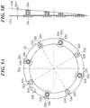
- FIG. 9A is a conceptual diagram showing a second assembly state of the tilt spacer 32 from the optical axis direction
- FIG. 9B is a schematic side cross-sectional view seen from a side surface of FIG. 9A .
- the tilt spacer 32 is provided with the through-holes 32 b at eight portions in total including four portions at the same phases as screw holes 10 c of a fixed barrel 10 and through-holes 40 c of a mount 40 , and four portions of positions with the phases shifted by 45 degrees from the screw holes 10 c .
- the through-holes 32 b at the eight portions in total protrude in parallel to the optical axis, and are formed penetrating the centers of the barrel portions of the different heights in the optical axis direction.
- reception surfaces 32 d and 32 e which come into contact with the mount 40 are coaxially provided with the through-holes 32 b on the distal end surface of each barrel part. Furthermore, barrel portions on which the reception surfaces 32 d are formed and barrel portions on which the reception surfaces 32 e are formed also have the different heights in the optical axis direction, and the reception surfaces 32 d and the reception surfaces 32 e are alternately disposed in a circumferential direction. Furthermore, the number of sets of the reception surfaces 32 d and 32 e is a multiple of the number of the screw holes 10 c (screws 50 ). It should be noted that FIG.
- the reception surfaces 32 c which come into contact with the reception surfaces 10 b of the fixed barrel 10 are disposed coaxially with the through-holes 32 b via the mount seat 20 on a side opposite to the reception surfaces 32 d and 32 e of the tilt spacer 32 .
- the reception surfaces 32 c and the reception surfaces 32 d and 32 e are disposed in substantially in parallel to each other.
- the screws 50 makes intervals between the reception surfaces 32 c and each of the reception surfaces 32 d and 32 e different, and also makes the heights of the reception surface 32 d and the reception surface 32 e different.
- the reception surfaces 32 c are disposed on a plane substantially perpendicular to the optical axis.
- the reception surfaces 32 c and the reception surfaces 32 d and 32 e are disposed substantially in parallel to each other in the optical axis direction.
- the reception surfaces 32 d and 32 e are disposed at the different heights, and further, the intervals in the optical axis direction between the reception surfaces 32 c and the reception surfaces 32 d , and the intervals in the optical axis direction between the reception surfaces 32 c and the reception surfaces 32 e differ from each other.
- the tilt spacer 32 is provided with positioning portions 32 a for the fixed barrel 10 at the same phases as the through-holes 32 b , and with a mark 32 g at one portion and marks 32 f at two portions in the assembly direction.
- a virtual plane 32 i ( FIGS. 8A and 8B ) defined by the reception surfaces 32 d
- a virtual plane 32 k FIGS. 9A and 9B ) defined by the reception surfaces 32 e
- angles 32 j and 32 m calculated by optical design, which are necessary for overall tilt adjustment with respect to a virtual plane 32 h defined by the reception surfaces 32 c
- an assembly mark of the reception surfaces 32 d and the virtual plane 32 i is a mark 32 f
- an assembly mark of the reception surfaces 32 e and the virtual plane 32 k is a mark 32 g.
- a virtual plane 32 i defined by the reception surface 32 d can be rotated for every 90 degrees in the circumferential direction about the optical axis x toward any of the directions.
- a virtual plane 32 k defined by the reception surface 32 e can be rotated per 90 degree in the circumferential direction about the optical axis x toward any of the directions.
- the tilt spacer 32 in the fixed barrel 10 based on the mark 32 f and the mark 32 g , it is possible to rotate the virtual plane 32 i and the virtual plane 32 k for every 90 degrees in the circumferential direction about the optical axis x toward any of the directions and perform tilt adjustment by the angle 32 j and the angle 32 m .
- the tilt spacer 32 in a tilt direction obtained from the measurement result of the tilt adjuster and positioning the tilt spacer 32 with respect to the fixed barrel 10 , the tilt can be adjusted, so that tilts of the image sensor and the lens group 200 are adjusted within predetermined values.
- the barrel portions on which the reception surfaces 32 d and 32 e are formed all have the different heights according to the arrangement relationship of the screws 50 , yet may partially have the same height if the virtual plane 32 i and the virtual plane 32 k can be formed.
- angles 32 j and 32 m are formed between the virtual plane 32 h and the virtual planes 32 i and 32 k .
- one of the virtual plane 32 i and the virtual plane 32 k may be formed in parallel to the virtual plane 32 h . By so doing, one spacer can be shared for both of the flat spacer and the tilt spacer.
- two patterns of the reception surfaces 32 d and the reception surfaces 32 e are provided.
- three patterns or more may be provided depending on the tilt adjustment range.
Landscapes
- Physics & Mathematics (AREA)
- General Physics & Mathematics (AREA)
- Optics & Photonics (AREA)
- Engineering & Computer Science (AREA)
- Multimedia (AREA)
- Signal Processing (AREA)
- Structure And Mechanism Of Cameras (AREA)
- Lens Barrels (AREA)
Applications Claiming Priority (3)
| Application Number | Priority Date | Filing Date | Title |
|---|---|---|---|
| JP2018013809A JP7051467B2 (ja) | 2018-01-30 | 2018-01-30 | 交換レンズの組立方法 |
| JPJP2018-013809 | 2018-01-30 | ||
| JP2018-013809 | 2018-01-30 |
Publications (2)
| Publication Number | Publication Date |
|---|---|
| US20190235198A1 US20190235198A1 (en) | 2019-08-01 |
| US10948687B2 true US10948687B2 (en) | 2021-03-16 |
Family
ID=67393351
Family Applications (1)
| Application Number | Title | Priority Date | Filing Date |
|---|---|---|---|
| US16/258,932 Active 2039-07-17 US10948687B2 (en) | 2018-01-30 | 2019-01-28 | Interchangeable lens and camera system |
Country Status (4)
| Country | Link |
|---|---|
| US (1) | US10948687B2 (enExample) |
| JP (1) | JP7051467B2 (enExample) |
| KR (1) | KR102354711B1 (enExample) |
| CN (1) | CN110095920B (enExample) |
Cited By (1)
| Publication number | Priority date | Publication date | Assignee | Title |
|---|---|---|---|---|
| USD1085197S1 (en) * | 2021-10-30 | 2025-07-22 | Gentex Corporation | Camera module |
Citations (16)
| Publication number | Priority date | Publication date | Assignee | Title |
|---|---|---|---|---|
| JP2003015010A (ja) | 2001-07-02 | 2003-01-15 | Canon Inc | 交換レンズ及びそれを有するカメラシステム |
| CN201294281Y (zh) | 2008-07-30 | 2009-08-19 | 索尼株式会社 | 电连接器辅助机构 |
| CN103135204A (zh) | 2012-10-31 | 2013-06-05 | 玉晶光电(厦门)有限公司 | 可携式电子装置与其光学成像镜头 |
| CN103163622A (zh) | 2011-12-16 | 2013-06-19 | 佳能株式会社 | 镜筒及摄像设备 |
| JP2014092624A (ja) | 2012-11-01 | 2014-05-19 | Fuji Xerox Co Ltd | 画像形成装置および画像形成プログラム |
| US20140184882A1 (en) | 2012-12-27 | 2014-07-03 | Panasonic Corporation | Inner focus lens system, interchangeable lens apparatus and camera system |
| CN103969923A (zh) | 2013-01-24 | 2014-08-06 | 蒙天培 | 能更换镜片且能调整镜片角度的枢接结构 |
| CN103969918A (zh) | 2013-01-25 | 2014-08-06 | 佳能株式会社 | 摄像照明设备 |
| CN104205800A (zh) | 2012-03-21 | 2014-12-10 | 佳能株式会社 | 摄像设备 |
| JP2016057093A (ja) | 2014-09-05 | 2016-04-21 | オムロン株式会社 | 反射型センサ |
| CN106556962A (zh) | 2017-01-05 | 2017-04-05 | 武汉微梦文化科技有限公司 | 一种镜头快换的拍摄架及摄影装置 |
| CN106664390A (zh) | 2014-03-31 | 2017-05-10 | 游图艾斯啊株式会社 | 相机用滤光器更换器结合装置 |
| CN206710778U (zh) | 2017-03-20 | 2017-12-05 | 东莞力途精密模具有限公司 | 一种用于照相机防水壳体的镜头快拆装置 |
| CN206835220U (zh) | 2017-06-23 | 2018-01-02 | 北京小米移动软件有限公司 | 镜头装置及运动相机 |
| US10571780B2 (en) * | 2016-09-16 | 2020-02-25 | Fujifilm Corporation | Lens unit, camera system, and lens mount |
| US10775585B2 (en) * | 2017-05-31 | 2020-09-15 | Canon Kabushiki Kaisha | Accessory, image pickup apparatus on which same is mountable, and camera system |
Family Cites Families (6)
| Publication number | Priority date | Publication date | Assignee | Title |
|---|---|---|---|---|
| JPH035110U (enExample) * | 1989-06-01 | 1991-01-18 | ||
| JPH11218659A (ja) * | 1998-01-30 | 1999-08-10 | Fuji Photo Optical Co Ltd | カメラのレンズ鏡胴 |
| JP2011099966A (ja) | 2009-11-05 | 2011-05-19 | Canon Inc | 光学素子保持装置 |
| JP2012048090A (ja) * | 2010-08-30 | 2012-03-08 | Canon Inc | レンズ鏡筒 |
| JP5810660B2 (ja) | 2011-06-17 | 2015-11-11 | リコーイメージング株式会社 | カメラボディ、レンズ鏡筒、及び、レンズ交換式カメラ |
| JP6150798B2 (ja) | 2013-01-25 | 2017-06-21 | オリンパス株式会社 | 交換レンズ鏡筒 |
-
2018
- 2018-01-30 JP JP2018013809A patent/JP7051467B2/ja active Active
-
2019
- 2019-01-22 KR KR1020190007835A patent/KR102354711B1/ko active Active
- 2019-01-24 CN CN201910067795.0A patent/CN110095920B/zh active Active
- 2019-01-28 US US16/258,932 patent/US10948687B2/en active Active
Patent Citations (17)
| Publication number | Priority date | Publication date | Assignee | Title |
|---|---|---|---|---|
| JP2003015010A (ja) | 2001-07-02 | 2003-01-15 | Canon Inc | 交換レンズ及びそれを有するカメラシステム |
| CN201294281Y (zh) | 2008-07-30 | 2009-08-19 | 索尼株式会社 | 电连接器辅助机构 |
| CN103163622A (zh) | 2011-12-16 | 2013-06-19 | 佳能株式会社 | 镜筒及摄像设备 |
| CN104205800A (zh) | 2012-03-21 | 2014-12-10 | 佳能株式会社 | 摄像设备 |
| CN103135204A (zh) | 2012-10-31 | 2013-06-05 | 玉晶光电(厦门)有限公司 | 可携式电子装置与其光学成像镜头 |
| CN103135204B (zh) | 2012-10-31 | 2016-08-17 | 玉晶光电(厦门)有限公司 | 可携式电子装置与其光学成像镜头 |
| JP2014092624A (ja) | 2012-11-01 | 2014-05-19 | Fuji Xerox Co Ltd | 画像形成装置および画像形成プログラム |
| US20140184882A1 (en) | 2012-12-27 | 2014-07-03 | Panasonic Corporation | Inner focus lens system, interchangeable lens apparatus and camera system |
| CN103969923A (zh) | 2013-01-24 | 2014-08-06 | 蒙天培 | 能更换镜片且能调整镜片角度的枢接结构 |
| CN103969918A (zh) | 2013-01-25 | 2014-08-06 | 佳能株式会社 | 摄像照明设备 |
| CN106664390A (zh) | 2014-03-31 | 2017-05-10 | 游图艾斯啊株式会社 | 相机用滤光器更换器结合装置 |
| JP2016057093A (ja) | 2014-09-05 | 2016-04-21 | オムロン株式会社 | 反射型センサ |
| US10571780B2 (en) * | 2016-09-16 | 2020-02-25 | Fujifilm Corporation | Lens unit, camera system, and lens mount |
| CN106556962A (zh) | 2017-01-05 | 2017-04-05 | 武汉微梦文化科技有限公司 | 一种镜头快换的拍摄架及摄影装置 |
| CN206710778U (zh) | 2017-03-20 | 2017-12-05 | 东莞力途精密模具有限公司 | 一种用于照相机防水壳体的镜头快拆装置 |
| US10775585B2 (en) * | 2017-05-31 | 2020-09-15 | Canon Kabushiki Kaisha | Accessory, image pickup apparatus on which same is mountable, and camera system |
| CN206835220U (zh) | 2017-06-23 | 2018-01-02 | 北京小米移动软件有限公司 | 镜头装置及运动相机 |
Non-Patent Citations (1)
| Title |
|---|
| Office Action issued in Chinese Appln. No. 201910067795.0 dated Dec. 31, 2020. English translation provided. |
Cited By (1)
| Publication number | Priority date | Publication date | Assignee | Title |
|---|---|---|---|---|
| USD1085197S1 (en) * | 2021-10-30 | 2025-07-22 | Gentex Corporation | Camera module |
Also Published As
| Publication number | Publication date |
|---|---|
| CN110095920B (zh) | 2021-09-07 |
| JP2019132937A (ja) | 2019-08-08 |
| KR20190092278A (ko) | 2019-08-07 |
| KR102354711B1 (ko) | 2022-01-24 |
| CN110095920A (zh) | 2019-08-06 |
| US20190235198A1 (en) | 2019-08-01 |
| JP7051467B2 (ja) | 2022-04-11 |
Similar Documents
| Publication | Publication Date | Title |
|---|---|---|
| JP5779179B2 (ja) | レンズユニット | |
| EP1821125B1 (en) | Lens apparatus and optical apparatus | |
| US10708471B2 (en) | Alignment of a camera system, camera system and alignment aid | |
| KR100397441B1 (ko) | 시시티브이카메라용렌즈의마운트시프트장치 | |
| US6318912B1 (en) | Adapter having a tilt and shift mechanism | |
| JP2005326777A (ja) | レンズ鏡胴 | |
| US10948687B2 (en) | Interchangeable lens and camera system | |
| CN110959128A (zh) | 拍摄装置 | |
| JP2011095324A (ja) | レンズ装置 | |
| US12197118B2 (en) | Optical system, imaging system, and imaging apparatus | |
| US20250147403A1 (en) | Lens apparatus and image pickup apparatus having the same | |
| JP4636740B2 (ja) | 交換レンズ及びそれを有するカメラシステム | |
| JP5585199B2 (ja) | レンズ鏡筒及び撮像装置 | |
| JP6704287B2 (ja) | レンズ鏡筒 | |
| JP2002196204A (ja) | 光学機器 | |
| JPH05292379A (ja) | カメラの固定焦点レンズ装置 | |
| JP2008158260A (ja) | レンズ鏡筒およびレンズ鏡筒の偏芯調整方法 | |
| JP2024004577A (ja) | 光学機器 | |
| JP6234096B2 (ja) | 焦点検出ユニット、及び撮像装置 | |
| JP2019028416A (ja) | 撮像装置 | |
| US20010010765A1 (en) | Lens unit structure for SLR digital camera | |
| JP3974266B2 (ja) | ファインダ光軸調整機構 | |
| JP2013145295A (ja) | レンズ鏡筒 | |
| JPH11174302A (ja) | レンズ鏡筒およびレンズの偏芯調整方法 | |
| JP2010044217A (ja) | レンズ鏡筒、撮像装置および製造方法 |
Legal Events
| Date | Code | Title | Description |
|---|---|---|---|
| FEPP | Fee payment procedure |
Free format text: ENTITY STATUS SET TO UNDISCOUNTED (ORIGINAL EVENT CODE: BIG.); ENTITY STATUS OF PATENT OWNER: LARGE ENTITY |
|
| AS | Assignment |
Owner name: CANON KABUSHIKI KAISHA, JAPAN Free format text: ASSIGNMENT OF ASSIGNORS INTEREST;ASSIGNOR:ISHIMASA, TORU;REEL/FRAME:048824/0880 Effective date: 20190117 |
|
| STPP | Information on status: patent application and granting procedure in general |
Free format text: PUBLICATIONS -- ISSUE FEE PAYMENT VERIFIED |
|
| STCF | Information on status: patent grant |
Free format text: PATENTED CASE |
|
| MAFP | Maintenance fee payment |
Free format text: PAYMENT OF MAINTENANCE FEE, 4TH YEAR, LARGE ENTITY (ORIGINAL EVENT CODE: M1551); ENTITY STATUS OF PATENT OWNER: LARGE ENTITY Year of fee payment: 4 |