US10864603B2 - Method and system for heat treatment of sheet metal - Google Patents
Method and system for heat treatment of sheet metal Download PDFInfo
- Publication number
- US10864603B2 US10864603B2 US15/559,384 US201615559384A US10864603B2 US 10864603 B2 US10864603 B2 US 10864603B2 US 201615559384 A US201615559384 A US 201615559384A US 10864603 B2 US10864603 B2 US 10864603B2
- Authority
- US
- United States
- Prior art keywords
- spot
- scanning pattern
- effective spot
- effective
- lines
- Prior art date
- Legal status (The legal status is an assumption and is not a legal conclusion. Google has not performed a legal analysis and makes no representation as to the accuracy of the status listed.)
- Active, expires
Links
- 238000010438 heat treatment Methods 0.000 title claims abstract description 99
- 238000000034 method Methods 0.000 title claims abstract description 63
- 229910052751 metal Inorganic materials 0.000 title claims abstract description 59
- 239000002184 metal Substances 0.000 title claims abstract description 59
- 238000009826 distribution Methods 0.000 claims abstract description 68
- 238000006073 displacement reaction Methods 0.000 claims description 22
- 230000006978 adaptation Effects 0.000 claims description 16
- 230000008859 change Effects 0.000 claims description 6
- 230000004044 response Effects 0.000 claims description 4
- 230000008569 process Effects 0.000 description 22
- 235000019589 hardness Nutrition 0.000 description 16
- 239000000047 product Substances 0.000 description 14
- 238000001816 cooling Methods 0.000 description 9
- 239000000463 material Substances 0.000 description 8
- 229910000831 Steel Inorganic materials 0.000 description 6
- 239000010959 steel Substances 0.000 description 6
- 238000005496 tempering Methods 0.000 description 6
- 238000013459 approach Methods 0.000 description 5
- 230000006698 induction Effects 0.000 description 5
- 238000004519 manufacturing process Methods 0.000 description 4
- 230000003287 optical effect Effects 0.000 description 4
- 238000012545 processing Methods 0.000 description 4
- 238000010791 quenching Methods 0.000 description 4
- 230000000171 quenching effect Effects 0.000 description 4
- 238000012546 transfer Methods 0.000 description 4
- 238000013021 overheating Methods 0.000 description 3
- 238000007493 shaping process Methods 0.000 description 3
- 238000003466 welding Methods 0.000 description 3
- 238000010521 absorption reaction Methods 0.000 description 2
- 238000005452 bending Methods 0.000 description 2
- 230000008901 benefit Effects 0.000 description 2
- 230000005670 electromagnetic radiation Effects 0.000 description 2
- 239000000835 fiber Substances 0.000 description 2
- 238000007731 hot pressing Methods 0.000 description 2
- 238000005461 lubrication Methods 0.000 description 2
- 239000007769 metal material Substances 0.000 description 2
- 239000011265 semifinished product Substances 0.000 description 2
- 239000000758 substrate Substances 0.000 description 2
- XLYOFNOQVPJJNP-UHFFFAOYSA-N water Substances O XLYOFNOQVPJJNP-UHFFFAOYSA-N 0.000 description 2
- 229910000838 Al alloy Inorganic materials 0.000 description 1
- CWYNVVGOOAEACU-UHFFFAOYSA-N Fe2+ Chemical compound [Fe+2] CWYNVVGOOAEACU-UHFFFAOYSA-N 0.000 description 1
- 229910000954 Medium-carbon steel Inorganic materials 0.000 description 1
- 229910052769 Ytterbium Inorganic materials 0.000 description 1
- 230000015572 biosynthetic process Effects 0.000 description 1
- 239000004566 building material Substances 0.000 description 1
- 239000003795 chemical substances by application Substances 0.000 description 1
- 238000010276 construction Methods 0.000 description 1
- 239000012809 cooling fluid Substances 0.000 description 1
- 239000000498 cooling water Substances 0.000 description 1
- 238000005520 cutting process Methods 0.000 description 1
- 238000009795 derivation Methods 0.000 description 1
- 238000013461 design Methods 0.000 description 1
- -1 dimensions Substances 0.000 description 1
- 238000010304 firing Methods 0.000 description 1
- 230000006870 function Effects 0.000 description 1
- 230000001939 inductive effect Effects 0.000 description 1
- 238000004093 laser heating Methods 0.000 description 1
- 230000005381 magnetic domain Effects 0.000 description 1
- 229910000734 martensite Inorganic materials 0.000 description 1
- 238000002844 melting Methods 0.000 description 1
- 230000008018 melting Effects 0.000 description 1
- 238000005459 micromachining Methods 0.000 description 1
- 238000012986 modification Methods 0.000 description 1
- 230000004048 modification Effects 0.000 description 1
- 238000005457 optimization Methods 0.000 description 1
- 230000002093 peripheral effect Effects 0.000 description 1
- 230000009467 reduction Effects 0.000 description 1
- 230000009528 severe injury Effects 0.000 description 1
- 238000010408 sweeping Methods 0.000 description 1
- 238000011282 treatment Methods 0.000 description 1
- NAWDYIZEMPQZHO-UHFFFAOYSA-N ytterbium Chemical compound [Yb] NAWDYIZEMPQZHO-UHFFFAOYSA-N 0.000 description 1
Images


Classifications
-
- C—CHEMISTRY; METALLURGY
- C21—METALLURGY OF IRON
- C21D—MODIFYING THE PHYSICAL STRUCTURE OF FERROUS METALS; GENERAL DEVICES FOR HEAT TREATMENT OF FERROUS OR NON-FERROUS METALS OR ALLOYS; MAKING METAL MALLEABLE, e.g. BY DECARBURISATION OR TEMPERING
- C21D10/00—Modifying the physical properties by methods other than heat treatment or deformation
- C21D10/005—Modifying the physical properties by methods other than heat treatment or deformation by laser shock processing
-
- B—PERFORMING OPERATIONS; TRANSPORTING
- B23—MACHINE TOOLS; METAL-WORKING NOT OTHERWISE PROVIDED FOR
- B23K—SOLDERING OR UNSOLDERING; WELDING; CLADDING OR PLATING BY SOLDERING OR WELDING; CUTTING BY APPLYING HEAT LOCALLY, e.g. FLAME CUTTING; WORKING BY LASER BEAM
- B23K26/00—Working by laser beam, e.g. welding, cutting or boring
- B23K26/352—Working by laser beam, e.g. welding, cutting or boring for surface treatment
- B23K26/359—Working by laser beam, e.g. welding, cutting or boring for surface treatment by providing a line or line pattern, e.g. a dotted break initiation line
-
- B—PERFORMING OPERATIONS; TRANSPORTING
- B23—MACHINE TOOLS; METAL-WORKING NOT OTHERWISE PROVIDED FOR
- B23K—SOLDERING OR UNSOLDERING; WELDING; CLADDING OR PLATING BY SOLDERING OR WELDING; CUTTING BY APPLYING HEAT LOCALLY, e.g. FLAME CUTTING; WORKING BY LASER BEAM
- B23K26/00—Working by laser beam, e.g. welding, cutting or boring
- B23K26/08—Devices involving relative movement between laser beam and workpiece
- B23K26/082—Scanning systems, i.e. devices involving movement of the laser beam relative to the laser head
-
- B—PERFORMING OPERATIONS; TRANSPORTING
- B23—MACHINE TOOLS; METAL-WORKING NOT OTHERWISE PROVIDED FOR
- B23K—SOLDERING OR UNSOLDERING; WELDING; CLADDING OR PLATING BY SOLDERING OR WELDING; CUTTING BY APPLYING HEAT LOCALLY, e.g. FLAME CUTTING; WORKING BY LASER BEAM
- B23K26/00—Working by laser beam, e.g. welding, cutting or boring
- B23K26/02—Positioning or observing the workpiece, e.g. with respect to the point of impact; Aligning, aiming or focusing the laser beam
- B23K26/06—Shaping the laser beam, e.g. by masks or multi-focusing
- B23K26/073—Shaping the laser spot
-
- C—CHEMISTRY; METALLURGY
- C21—METALLURGY OF IRON
- C21D—MODIFYING THE PHYSICAL STRUCTURE OF FERROUS METALS; GENERAL DEVICES FOR HEAT TREATMENT OF FERROUS OR NON-FERROUS METALS OR ALLOYS; MAKING METAL MALLEABLE, e.g. BY DECARBURISATION OR TEMPERING
- C21D1/00—General methods or devices for heat treatment, e.g. annealing, hardening, quenching or tempering
- C21D1/06—Surface hardening
- C21D1/09—Surface hardening by direct application of electrical or wave energy; by particle radiation
-
- C—CHEMISTRY; METALLURGY
- C21—METALLURGY OF IRON
- C21D—MODIFYING THE PHYSICAL STRUCTURE OF FERROUS METALS; GENERAL DEVICES FOR HEAT TREATMENT OF FERROUS OR NON-FERROUS METALS OR ALLOYS; MAKING METAL MALLEABLE, e.g. BY DECARBURISATION OR TEMPERING
- C21D10/00—Modifying the physical properties by methods other than heat treatment or deformation
-
- C—CHEMISTRY; METALLURGY
- C21—METALLURGY OF IRON
- C21D—MODIFYING THE PHYSICAL STRUCTURE OF FERROUS METALS; GENERAL DEVICES FOR HEAT TREATMENT OF FERROUS OR NON-FERROUS METALS OR ALLOYS; MAKING METAL MALLEABLE, e.g. BY DECARBURISATION OR TEMPERING
- C21D9/00—Heat treatment, e.g. annealing, hardening, quenching or tempering, adapted for particular articles; Furnaces therefor
- C21D9/46—Heat treatment, e.g. annealing, hardening, quenching or tempering, adapted for particular articles; Furnaces therefor for sheet metals
-
- B—PERFORMING OPERATIONS; TRANSPORTING
- B23—MACHINE TOOLS; METAL-WORKING NOT OTHERWISE PROVIDED FOR
- B23K—SOLDERING OR UNSOLDERING; WELDING; CLADDING OR PLATING BY SOLDERING OR WELDING; CUTTING BY APPLYING HEAT LOCALLY, e.g. FLAME CUTTING; WORKING BY LASER BEAM
- B23K2101/00—Articles made by soldering, welding or cutting
- B23K2101/006—Vehicles
-
- C—CHEMISTRY; METALLURGY
- C21—METALLURGY OF IRON
- C21D—MODIFYING THE PHYSICAL STRUCTURE OF FERROUS METALS; GENERAL DEVICES FOR HEAT TREATMENT OF FERROUS OR NON-FERROUS METALS OR ALLOYS; MAKING METAL MALLEABLE, e.g. BY DECARBURISATION OR TEMPERING
- C21D1/00—General methods or devices for heat treatment, e.g. annealing, hardening, quenching or tempering
- C21D1/62—Quenching devices
- C21D1/673—Quenching devices for die quenching
-
- C—CHEMISTRY; METALLURGY
- C21—METALLURGY OF IRON
- C21D—MODIFYING THE PHYSICAL STRUCTURE OF FERROUS METALS; GENERAL DEVICES FOR HEAT TREATMENT OF FERROUS OR NON-FERROUS METALS OR ALLOYS; MAKING METAL MALLEABLE, e.g. BY DECARBURISATION OR TEMPERING
- C21D2221/00—Treating localised areas of an article
- C21D2221/02—Edge parts
-
- C—CHEMISTRY; METALLURGY
- C21—METALLURGY OF IRON
- C21D—MODIFYING THE PHYSICAL STRUCTURE OF FERROUS METALS; GENERAL DEVICES FOR HEAT TREATMENT OF FERROUS OR NON-FERROUS METALS OR ALLOYS; MAKING METAL MALLEABLE, e.g. BY DECARBURISATION OR TEMPERING
- C21D9/00—Heat treatment, e.g. annealing, hardening, quenching or tempering, adapted for particular articles; Furnaces therefor
- C21D9/46—Heat treatment, e.g. annealing, hardening, quenching or tempering, adapted for particular articles; Furnaces therefor for sheet metals
- C21D9/48—Heat treatment, e.g. annealing, hardening, quenching or tempering, adapted for particular articles; Furnaces therefor for sheet metals deep-drawing sheets
-
- Y—GENERAL TAGGING OF NEW TECHNOLOGICAL DEVELOPMENTS; GENERAL TAGGING OF CROSS-SECTIONAL TECHNOLOGIES SPANNING OVER SEVERAL SECTIONS OF THE IPC; TECHNICAL SUBJECTS COVERED BY FORMER USPC CROSS-REFERENCE ART COLLECTIONS [XRACs] AND DIGESTS
- Y02—TECHNOLOGIES OR APPLICATIONS FOR MITIGATION OR ADAPTATION AGAINST CLIMATE CHANGE
- Y02P—CLIMATE CHANGE MITIGATION TECHNOLOGIES IN THE PRODUCTION OR PROCESSING OF GOODS
- Y02P10/00—Technologies related to metal processing
- Y02P10/25—Process efficiency
Definitions
- the present invention relates to the heat treatment of sheet metal, for example, sheet metal for use in or used in metal products, for example, in structural components for vehicles, such as motor vehicles.
- DE-102013008494-A1 discloses a method for producing a metal vehicle component including the steps of localized heating of a sheet metal workpiece in a first heating station, shaping the workpiece in a first shaping station using a tool for cold forming of workpieces, and heating the shaped workpiece in a second heating station to provide it with desired mechanical characteristics. It is explained that thereby, it is possible to provide high strength components for vehicles, components that feature a ductility which, at least in certain regions, is enhanced due to the heating in the second station. This is desirable in order to provide for an adequate performance in the case of a crash.
- DE-102011118285-A1 likewise discloses heat treatment of a metallic vehicle component, more specifically, of a semi-finished or finished product of an aluminum alloy, in order to provide for a desired performance in the case of a crash. This is achieved by subjecting the product or the semi-finished product to heat treatment in a selected area, to increase the ductility in that area.
- DE-102011118285-A1 suggests heating by induction but also mentions to option of heating using a laser or a gas burner.
- DE-102011054866-A1 explains how it was known in the art to produce high strength steel components by hot forming a workpiece, whereby the workpiece is heated above the austenization temperature, shaped in a press, and cooled for quenching. It is explained that the high strength can render further operations on the hardened object, such as the establishment of perforations, difficult.
- DE-102011054866-A1 addresses this by carrying out the shaping step so that certain areas protrude, whereafter the protruding portion can be removed in a separate step.
- EP-2570205-A1 teaches how a sheet metal or steel plate can be shaped in a press, with an arrangement that allows for selected heating and/or cooling, such as to provide selected areas of the shaped object with desired characteristics in terms of hardness and/or ductility.
- U.S. Pat. No. 8,847,126-B2 teaches hot pressing and hardening, wherein the heating is carried out so that different regions are heated differently, by using electromagnetic radiation for heating and applying a plate member which shields, absorbs and/or reflects the applied electromagnetic wave.
- U.S. Pat. No. 8,480,163-B2 teaches a vehicle center pillar provided with two weak portions. It is explained that this can be obtained by avoiding quenching of these portions. This can be achieved by adapting the way in which the cooling water cools different portions of the member during manufacture.
- U.S. Pat. No. 7,070,228-B2 refers to a press formed article such as a center pillar or the like, with regions featuring different levels of hardness.
- U.S. Pat. No. 7,070,228-B2 is focused on induction hardening.
- US-2002/0069945-A1 teaches a method for manufacturing structural parts for automobile body construction, including hardening by inductive heating followed by cooling.
- US-2012/0237387-A1 teaches how a steel member can be provided with portions of lesser mechanical resistance using, for example, laser light.
- U.S. Pat. No. 8,272,681-B2 teaches how a profile component can be provided with regions that are hardened and other regions that are not hardened.
- the use of laser light is suggested to be useful for heating a comparatively small spatially delimited region of a sheet metal semi-finished product.
- DE-102004023579-A1 teaches heating of a hard steel component to produce softer regions, so as to allow for the use of conventional assembly means such as welding when assembling the component.
- a laser can be used to produce the heating.
- US-2010/0086803-A1 teaches how a hot-formed and press-hardened metal component can be heat treated so as to facilitate bending, using a laser beam.
- WO-2012/156084-A1 teaches a method for heat treating a hardenable sheet metal component, in particular for a motor vehicle.
- the method consists of press hardening the sheet metal component in a forming tool, removing the sheet metal component from said forming tool, and forming locally defined soft areas of the sheet metal component by locally tempering predetermined sub-areas of the sheet metal component using a laser beam.
- DE-102010049330-A1 teaches how profile components for vehicles are shaped and how they subsequently are subjected to a heat treatment using laser light, wherein portions are hardened by heating followed by cooling.
- EP-2541093-A1 and EP-2565489-A1 relate to heat treatment of impact absorbing members in vehicles using laser light.
- JP-6-226479-A discusses butt welding of a front pillar part and a center pillar part, etc. Softened parts are provided through a softening treatment using a laser beam near peripheral parts of the metal sheet.
- U.S. Pat. No. 8,555,507-B2 teaches how a rigid vehicle component formed by hot stamping is provided with areas of lower rigidity by laser heat treatment, thereby improving the collision absorption performance.
- WO-2012/025171-A1 likewise relates to heat treatment of a profiled component for vehicles, using laser light or induction heating.
- EP-2561946-A1 teaches the use of a diode laser beam to convert a localized zone in a hot stamped vehicle component into an energy absorption zone in the event of a collision.
- FR-2825375-A1 teaches localized hardening of structural metal sheets using induction or diode lasers.
- the laser beam is typically scanned once over the region to be treated.
- a typical example is shown in FIG. 7 of the above-mentioned document US-2012/0237387-A1, in which a steel sheet is moved in relation to a laser source, so that a plurality of heat treated tracks are established, with widths corresponding to the width of the laser beam.
- EP-1308525-A2 and U.S. Pat. No. 4,797,532-A teach how laser heating of a track substantially wider than the width of the laser beam can be achieved by combining a relative movement between the surface to be heated and the laser beam in one direction, with a back-and-forth movement in another direction perpendicular to the first direction, so that the projected laser spot follows a sinusoidal or meandering path on the surface of the workpiece.
- EP-0965516-A1 teaches, in the context of laser hardening of selected portions of a fifth wheel plate, the use of optics for establishing the desired cross section of the laser beam, including the distribution of power over the cross section.
- DE-3905551-A1 teaches, in the context of the hardening of crankshafts, the use of optics for adapting the power distribution over the cross section of the laser beam to the geometry of the surface being hardened.
- the heated areas are sometimes arranged as bands or strips having a substantially constant width. This applies both to hardening and to tempering, for example, tempering of a previously hardened object to establish selected areas where the material is softer and/or more ductile.
- tempering for example, tempering of a previously hardened object to establish selected areas where the material is softer and/or more ductile.
- heating the entire track in the same way may be suboptimal, for example, at the beginning and the end of the track, where the cooling due to the conduction of heat differs from the one in the middle of the track.
- US-2009/0272464-A1 relates to grain-oriented electrical sheet and discusses laser firing to introduce residual stress for magnetic domain control.
- US-2003/0132208-A1 discusses laser micromachining employing a fast steering mirror to move a laser spot having a focused spot size in a desired pattern on a substrate to remove a target area that is larger than the focused spot size on the substrate.
- a first aspect of the invention relates to a method for heat treatment of an object of sheet metal, comprising the step of heating at least one selected portion of the object using an energy beam;
- the beam is projected onto a surface of the object so as to produce a primary spot on the object, the beam being repetitively scanned in two dimensions in accordance with a first scanning pattern so as to establish an effective spot on the object, said effective spot having a two-dimensional energy distribution,
- said effective spot is displaced in relation to the surface of the object to progressively heat said at least one selected portion of the object. That is, at a given moment, the effective spot generated by the two-dimensional scanning of the primary spot heats part of said selected portion, and the effective spot is displaced over the surface of the object until the selected portion has been heated as desired.
- the sheet metal object can be any kind of sheet metal object, including a portion of sheet metal coming from a roll, a plate of sheet metal, a sheet metal blank intended to be shaped into specific sheet metal object or workpiece at a later stage, a sheet metal component already shaped in, for example, a press or tool, using for example cold stamping/forming or hot stamping/forming, a component comprising one or more sheet metal portions and optionally other elements, interconnected by, for example, welding, screws, bolts, or other means, etc.
- the energy beam is a beam of electromagnetic radiation, for example, a laser beam.
- the effective spot can be created and adapted using, for example, any of the techniques described in WO-2014/037281-A2, which is incorporated herein by reference.
- WO-2014/037281-A2 is primarily focused on the laser hardening of journals of crankshafts and to a substantial extent focuses on the specific problem of avoiding overheating of the areas adjacent to the oil lubrication holes, it has been found that the principles disclosed therein regarding the scanning of the laser beam can be applied also to the heat treatment of sheet metal, including tasks such as the selective reduction of the hardness—for example, by tempering—of portions of previously hardened workpieces.
- the displacement of the effective spot in relation to the surface of the sheet metal object can be carried out in accordance with a second scanning pattern. That is, the real/primary spot, that is, the spot that is produced by the beam at any given moment, is scanned in accordance with a first scanning pattern to create the effective spot, and this effective spot can be displaced in accordance with the second scanning pattern.
- two types of movement are combined or overlaid: the movement of the primary spot in accordance with the first scanning pattern, and the movement of the effective spot in accordance with the second scanning pattern, which in some embodiments of the invention can be a simple straight line.
- two-dimensional energy distribution refers to the manner in which the energy applied by the energy beam is distributed over the effective spot, for example, during one sweep of the beam along the first scanning pattern.
- the term “two-dimensional energy distribution” refers to how the energy is distributed along and across the surface of the object, that is, to the energy distribution along and across the effective spot as projected onto the surface of the object.
- the present invention allows for a relatively rapid heating of a substantial area of the surface of the sheet metal object, due to the fact that the effective spot can have a substantial size, such as, for example, more than 4, 10, 15, 20 or 25 times the size (area) of the primary spot.
- a substantial size such as, for example, more than 4, 10, 15, 20 or 25 times the size (area) of the primary spot.
- heating a certain region or area of the sheet metal object to a desired extent in terms of temperature and duration can be accomplished more rapidly than if the heating is carried out by simply displacing the primary spot over the entire area, for example, following a sinusoidal or meandering pattern, or a straight line.
- the use of an effective spot having a relatively large area allows for high productivity while still allowing the relevant portion or portions of the surface to be heated for a relatively substantial amount of time, thereby allowing for, for example, less aggressive heating without compromising productivity.
- the primary spot can have an area substantially smaller than the one of the effective spot.
- the primary spot has a size of less than 4 mm 2 , such as less than 3 mm 2 , at least during part of the process.
- the size of the primary spot can be modified during the process, so as to optimize the way in which each specific portion of the object is being heat treated, in terms of quality and productivity.
- an effective spot created by scanning the primary spot repetitively in two dimensions in accordance with a first scanning pattern makes it possible to establish an effective spot having a selected two-dimensional energy distribution, which is substantially independent of the specific optics (lenses, mirrors, etc.) being used, and which can be tailored and adapted to provide for an enhanced or optimized heating of the sheet metal, from different points of view, including the speed with which the heat treatment is completed (for example, in terms of cm 2 per minute or in terms of terminated units per hour), and quality.
- the heat can be distributed so that a leading portion of the effective spot has a higher energy density than a trailing portion, thereby increasing the speed with which a desired temperature of the surface is reached, whereas the trailing portion can serve to maintain the heating for a sufficient time to reach a desired depth and/or quality, thereby optimizing the velocity with which the effective spot can be displaced in relation to the surface of the object, without renouncing on the quality of the heat treatment.
- the two-dimensional energy distribution can be adapted in relation to the sides of the effective spot, depending on the characteristics of the object, for example, so as to apply less heat in areas adjacent to an edge of the object or an opening in the object, where cooling due to heat transfer is slower, or so as to apply less heat in areas already featuring a relatively high temperature, for example, due to heating that has taken place recently.
- the effective spot can be adapted in accordance to the tri-dimensional shape of the object, for example, to adapt the heating to the curvature, width, etc., of the object in the area being heated, and to the configuration of the portion of the object that is to be heated.
- the shape of the effective spot and/or the two-dimensional energy distribution can be adapted whenever needed, thereby adapting the process to the specific part of the object that is to be heated at any given moment.
- the two-dimensional energy distribution can be varied as a function of the respective irradiation site on the object, taking into account, for example, the heat removal capability of a surrounding region.
- the two-dimensional energy distribution can be varied taking into account desired characteristics of the product in different regions of the product, such as different requirements on hardness, rigidity, softness, ductility, etc.
- Adaptation can more frequently be carried out, at least in part, by merely adapting the software controlling the scanning of the primary spot and, thereby, the two-dimensional energy distribution of the effective spot.
- first scanning pattern does not imply that the primary spot must always follow one and the same scanning pattern when creating the effective spot, but is merely intended to distinguish the scanning pattern of the primary spot that is used to create the effective spot, from the pattern with which the effective spot is displaced or scanned in relation to the object being subjected to the heat treatment; the scanning pattern followed by the effective spot is sometimes referred to as a second scanning pattern.
- the velocity or mean or average velocity with which the primary spot is displaced in accordance with the first scanning pattern is substantially higher than the velocity with which the effective spot is displaced in relation to the surface of the object.
- a high velocity of the primary spot along the first scanning pattern reduces the temperature fluctuations within the effective spot during each sweep of the primary spot along the first scanning pattern.
- the area being heated at each moment substantially corresponded to the primary spot projected by the beam onto the surface. That is, in prior art arrangements, the area being heated at each moment has a size that substantially corresponds to the one of the primary spot, and the width of the track being heated substantially corresponds to the width of the primary spot in the direction perpendicular to the direction in which the primary spot is being displaced, which in turn is determined by the laser and the optics used.
- the present invention does not exclude the possibility of carrying out part of the heat treatment operating with the primary spot in a conventional way.
- the primary spot can be displaced to carry out the heating in correspondence with the outline or contour of a region to be heated, or to carry out heating of certain details of the object being heated
- the effective spot described above can be used to carry out the heating of other parts or regions of the surface, such as the interior or main portion of a region to be heated.
- the skilled person will chose the extent to which the effective spot rather than the primary spot will be used to carry out the heating, depending on issues such as productivity and the need to carefully tailor the outline of a region to be heated or a certain portion of an object being subjected to heat treatment.
- the primary spot can be used to outline a region to be heated, while the effective spot is used to heat the surface within the outlined region.
- the first scanning pattern can be modified to reduce the size of the effective spot until it ends up corresponding to the primary spot, and vice-versa.
- the effective spot it is not necessary to use the effective spot to carry out all of the heating that has to take place during the heat treatment of the object.
- at least part of the heat treatment is carried out using the effective spot described above.
- the two-dimensional energy distribution of the effective spot is dynamically adapted during displacement of the effective spot in relation to the surface of the object.
- adaptation of the effective spot to the area or region of the object currently being heated can be accomplished.
- the expression dynamic adaptation is intended to denote the fact that adaptation can take place dynamically during displacement of the effective spot. Different means can be used to achieve this kind of dynamic adaptation, some of which are mentioned below.
- the scanning system can be operated to achieve the dynamic adaptation (for example, by adapting the operation of galvanic mirrors or other scanning means, so as to modify the first scanning pattern and/or the velocity of the primary spot along the scanning pattern or along one or more segments or portions thereof), and/or the beam power and/or the size of the primary spot can be adapted.
- Open-loop or closed-loop control can be used for controlling the dynamic adaptation.
- the dynamic adaptation can affect the way in which the energy is distributed within a given area of the effective spot, and/or the actual shape of the effective laser spot, and thus the shape of the area being heated at any given moment (disregarding the fact that the primary spot is moving, and just considering the effective spot).
- the length and/or the width of the effective spot can be adapted dynamically during the process.
- adaptation of the two-dimensional energy distribution of the effective spot is carried out by adapting the power of the beam, such as by selectively turning the beam on and off.
- This includes interruption of the beam at its source, as well as other options such as interruption of the beam by interference with the path of the beam, for example with a shutter, and combinations thereof.
- the laser beam can be switched on and off very rapidly, thus making it possible to obtain a desired energy distribution by turning the laser beam on and off while following the scanning pattern.
- heating can be achieved by turning the laser beam on during certain lines or parts of lines of the scanning pattern.
- a pixelized approach can be adopted, according to which the two-dimensional energy distribution is determined by the on/off state of the laser during the different portions or segments of the first scanning pattern.
- adaptation of the two-dimensional energy distribution of the effective spot is carried out by adapting the first scanning pattern.
- adaptation of the two-dimensional energy distribution of the effective spot is carried out by adapting the velocity with which the primary spot moves along at least a portion of the first scanning pattern.
- the two-dimensional energy distribution can be adapted by adapting, for example, the power of the beam—for example, by switching between different power states such as between on and off—, and/or by adapting the scanning pattern—for example, adding or leaving out segments, or modifying the orientation of segments, or completely changing a pattern for another one—, and/or by adapting the velocity with which the beam moves along the scanning pattern, such as along one or more segments thereof.
- the choice between different means for adapting the two-dimensional energy distribution can be made based on circumstances such as the capacity of the equipment to rapidly change between power states of the beam, and on the capacity of the scanner to modify the pattern to be followed and/or the speed with which the primary spot moves along the scanning pattern.
- focus of the beam is dynamically adapted during displacement of the primary spot along the first scanning pattern and/or during displacement of the effective spot in relation to the object being produced.
- the laser focus along the optical axis can be dynamically modified during the process, for example, so as to vary or maintain the size of the primary laser spot while it is being displaced along the first scanning pattern, and/or while the effective laser spot is being displaced in relation to the surface of the object.
- the optical focus can be adapted to keep the size of the primary spot constant while the primary spot is moving over the surface of the object (for example, to compensate for varying distances between the laser source or the scanner and the position of the primary laser spot on the surface of the object).
- the size of the primary spot is dynamically adapted during displacement of the primary spot along the first scanning pattern and/or during displacement of the effective spot in relation to the surface of the object, so as to modify the two-dimensional energy distribution and/or the size of the effective spot.
- the effective spot comprises a leading portion having a higher energy density than a trailing portion of the effective spot (this arrangement can be preferred when it is desired to rapidly reach a certain temperature, and thereafter provide sufficient energy input to, for example, keep the material at the required temperature for a certain amount of time), or the effective spot comprises a leading portion having a lower energy density than a trailing portion of the effective spot (this arrangement can be preferred when it is desired to first pre-heat the material for some time, prior to making it reach a certain temperature).
- the effective spot comprises an intermediate portion having a higher energy density than a leading portion and a trailing portion of the effective spot.
- the effective spot features a substantially uniform energy distribution, with a substantially constant energy density throughout the effective spot.
- the two-dimensional energy distribution can be adapted dynamically while the method is being carried out, for example, so that it is different in relation to different portions of the surface of the object.
- the mean or average velocity of the primary spot along the first scanning pattern is substantially higher than the mean or average velocity with which the effective spot is displaced in relation to the surface of the object.
- the average velocity of the primary spot along the first scanning pattern can preferably be at least ten times higher, more preferably at least 100 times higher, than the average velocity with which the effective spot is displaced in relation to the object.
- a high velocity of the primary spot reduces the temperature fluctuations within the effective spot during one sweep of the primary spot along the first scanning pattern.
- the beam is scanned in accordance with said first scanning pattern so that said first scanning pattern is repeated by the beam with a frequency of more than 10, 25, 50, 75, 100, 150, 200 or 300 Hz (i.e., repetitions of the scanning pattern per second).
- a high repetition rate can be appropriate to reduce or prevent non-desired temperature fluctuations in the areas being heated by the effective spot, between each scanning cycle, that is, between each sweep of the beam along the first scanning pattern.
- the first scanning pattern remains constant, and in other embodiments of the invention, the first scanning pattern is modified between some or all of the sweeps of the beam along the first scanning pattern.
- the size (that is, the area) of the effective spot such as the average size of the effective spot during the process or the size of the effective spot during at least one moment of the process, such as the maximum size of the effective spot during the process, is more than 4, 10, 15, 20 or 25 times the size of the primary spot.
- a primary spot having a size in the order of 3 mm 2 can be used to create an effective spot having a size of more than 10 mm 2 , such as more than 50 or 100 mm 2 or more.
- the size of the effective spot can be dynamically modified during the process, but a large average size can often be preferred to enhance productivity, and a large maximum size can be useful to enhance productivity during at least part of the process.
- the method can be carried out under the control of electronic control means, such as a computer.
- the first scanning pattern is a polygonal scanning pattern comprising a plurality of lines.
- the first scanning pattern can be a polygon such as a triangle, a square or a rectangle, a pentagon, a hexagon, a heptagon, an octagon, etc.
- the polygon does not need to be a perfect polygon, for example, the lines making up the polygon can in some embodiments be more or less curved and the edges of the polygon where the lines meet can be rounded, etc.
- the first scanning pattern comprises a plurality of lines, such as a plurality of straight or curved lines, which in some embodiments of the invention are arranged substantially parallel with each other. In some embodiments of the invention, there are two, three, four or more of these lines.
- the first scanning pattern comprises at least three segments, and said scanning of the energy beam is carried out so that said beam or spot follows at least one of said segments more frequently than it follows at least another one of said segments.
- This arrangement is advantageous in that it enhances flexibility and the way in which the scanning pattern can be used to provide an adequate and, whenever desired, symmetric or substantially symmetric energy distribution.
- one of said segments can be used as a path or bridge followed by the beam when moving between two other segments, so that the transfer of the spot projected by the beam between different portions (such as an end and a beginning) of the first scanning pattern can be carried out using segments (such as intermediate segments) of the scanning pattern for the transfer, whereby the transfer can often be carried out without turning off the beam and without distorting the symmetry of the two-dimensional energy distribution, when such symmetry is desired.
- the first scanning pattern comprises at least three substantially parallel straight or curved lines distributed one after the other in a first direction, said lines generally extending in a second direction, wherein said at least three lines comprise a first line, at least one intermediate line, and a last line arranged one after the each other in said first direction, wherein said scanning of the beam is carried out so that said beam or spot follows said intermediate line more frequently than said beam follows said first line and/or said last line. That is, for example, the beam can on an average follow said intermediate line twice as often as it follows said first line and said last line, for example, the beam can travel along the intermediate line each time it moves from the first line towards the last line, and vice-versa. That is, the intermediate line or lines can serve as a kind of bridge followed by the projected spot when moving between the first and the last line.
- the first scanning pattern comprises at least three substantially parallel lines or segments, distributed one after the other in a first direction, such as in the direction along which the effective spot travels during the process, said lines extending in a second direction, such as in a direction perpendicular the first direction.
- said at least three lines comprise a first line, at least one intermediate line, and a last line, arranged after each other in said first direction, and the scanning of the beam is carried out so that the projected spot is scanned along said lines according to a sequence in accordance with which the spot, after following said first line, follows said intermediate line, said last line, said intermediate line, and said first line, in that order.
- the scanning has to start with the first line, but just indicates the sequence according to which the beam tracks or follows the above-mentioned lines of the scanning pattern. Also, it does not exclude that in between (such as before or after) following some or all of the lines indicated above, the beam may follow other lines, such as lines interconnecting the first, last and intermediate lines, and/or additional intermediate lines.
- the beam after moving along the first line, the beam always follows said intermediate line twice before moving along the first line again.
- a more straight-forward approach might have been to carry out the scanning so that after said last line the beam and its projected spot return directly to said first line, it has been found that the sequence followed according to these embodiments of the invention is suitable to achieve a symmetric energy distribution about an axis of symmetry extending in said first direction.
- the scanning pattern comprises a plurality of said intermediate lines.
- the number of lines can be chosen by the operator or process designer or equipment designer depending on, for example, the size of the primary spot projected by the beam and the desired extension of the effective spot, for example, in the first direction.
- a minimum number of lines can in some embodiments be three lines, but in many practical implementations a larger number of lines can be used, such as four, five, six, ten or more lines, when counting the first, the last and the intermediate lines.
- the number of lines is modified to modify the energy distribution, while the effective spot is travelling along the surface area where heating of the sheet metal material is to take place.
- the primary spot is displaced with a higher velocity along said at least one intermediate line than along said first line and last line. This is often preferred in order to achieve an adequate energy distribution in said first direction, at least during a portion or a substantial portion of the process.
- the higher velocity of the beam when moving along the intermediate lines, or at least when moving along one or some of them compensates for the fact that the beam moves along said intermediate lines twice as often as it moves along the first and last lines.
- the velocity of the primary spot along the intermediate lines can in some embodiments of the invention be about twice the velocity of the primary spot along the first and/or last lines.
- the velocity can be different for different intermediate lines.
- the velocity for each line can be chosen in accordance with a desired energy distribution in the first direction.
- the velocity with which the effective spot is displaced along different lines or segments of the scanning pattern can be dynamically modified while the effective spot is travelling along the area where heating of the sheet metal material is to take place, for example, to adapt the energy distribution to optimize the way in which the process is taking place, for example, in order to increase the quality of the product, for example, of the hardening and/or tempering.
- the scanning pattern further comprises lines extending in said first direction, between the ends of the first, last and intermediate lines, whereby the primary spot follows said lines extending is said first direction when moving between said first line, said intermediate lines and said last line.
- the primary spot is displaced with a higher velocity along said lines extending in the first direction, than along said first line and said last line, at least during part of the process.
- the beam is displaced along said first scanning pattern without switching the beam on and off and/or while maintaining the power of the beam substantially constant.
- This makes it possible to carry out the scanning at a high speed without taking into account the capacity of the equipment, such as a laser equipment, to switch between different power levels, such as between on and off, and it makes it possible to use equipment that may not allow for very rapid switching between power levels. Also, it provides for efficient use of the available output power, that is, of the capacity of the equipment in terms of power.
- the energy beam is a laser beam.
- a laser beam is often preferred due to issues such as cost, reliability, and availability of appropriate scanning systems.
- the power of the laser beam is higher than 1 kW, such as higher than 3 kW, higher than 4 kW, higher than 5 kW or higher than 6 kW, at least during part of the process.
- lasers having relatively low output powers have often been used. For example, in EP-1308525-A2 discussed above, a beam power of 600 W is suggested.
- the laser spot that at a certain moment is heating a surface portion corresponds to the primary spot, having a relatively small surface area.
- a lower power output can be preferred to avoid overheating.
- the power of the laser can be distributed over an effective laser spot having a surface area substantially larger than the one of the primary laser spot. That is, with the present approach, based on the creation of a larger effective laser spot, higher powers can be used, whereby the productivity can be enhanced.
- the first scanning pattern can be implemented in line with the teachings of WO-2014/037281-A2, for example, in line with the teachings in relation to FIGS. 9-11 thereof.
- the object is a vehicle body component, such as a structural component, for example, a pillar such as a so-called B-pillar or central pillar.
- a vehicle body component such as a structural component, for example, a pillar such as a so-called B-pillar or central pillar.
- the method described above is useful to facilitate the optimization of the heating of selected portions of vehicle components, for example, to harden certain regions or to temper certain regions. For example, one or more portions of a previously hardened object or region can be softened, that is, made less hard, using the method of the invention.
- the method makes it easy to tailor the way the heating takes place, so as to optimize it and adapt it to a specific product and to the desired characteristics of the product, without any need for complex optics.
- adaptation can be carried out by adapting software, especially software controlling a scanner for displacing the laser beam.
- the object is a previously at least partially hardened object
- the step of heating at least one selected portion of the object using an energy beam is carried out so as to reduce the hardness of at least a portion of the object, for example, by tempering said portion, which can be a previously hardened portion.
- a sheet metal object such as structural vehicle component, such as a vehicle pillar, which can have been hot formed and hardened during the hot stamping or hot forming step (this is also known as “press hardening”), can be heat treated in accordance with the method of the invention, whereby the heating can be controlled by controlling the two-dimensional energy distribution of the effective laser spot, adapting it as desired to the layout of the surface and to the geometry of the portion to be heat treated.
- the heat treatment can serve to reduce the hardness in one or more areas of the object.
- areas with reduced hardness can be useful to assure that deformation will take place in a certain manner in the case of an impact, or to allow certain assembly operations to be carried out, or to facilitate cutting of the component after an accident, etc.
- the object is a structural vehicle component
- the step of heating at least one selected portion of the object using an energy beam is carried out so as to establish at least one preferred zone of deformation in the case of a crash.
- a vehicle pillar component with high hardness can be treated in accordance with the invention in certain regions, whereby softer or more ductile portions are established, thereby substantially predetermining the manner in which deformation will take place in the case of a collision or when the vehicle is turned over and lands on its side or upside down.
- the two-dimensional energy distribution of the effective spot is dynamically adapted during displacement of the effective spot in relation to the surface of the object, in response to at least one change in angle between the energy beam and a portion of the surface of the object being heated by the effective spot, for example, adapting the two-dimensional energy distribution, including the shape and the size of the effective spot as well as the two-dimensional energy distribution within the effective spot, to the curvature and/or bends in the surface, and/or to variations in the angle at which the surface is oriented in relation to the scanner.
- At least one of the power of the energy beam, the first scanning pattern and the velocity with which the primary spot moves along at least a portion of the first scanning pattern is/are adapted in response to at least one change in angle between the energy beam and a portion of the surface of the object being heated by the effective spot.
- teachings of the present invention can be used to adequately control the heating when the effective spot moves over a curved surface, over a bent portion of the object, or when the effective spot moves from a first portion or region of the object to another portion or region placed at an angle with the first portion or region, etc.
- This can be very useful in order to, for example, assure a good quality of the heating, when the object being heated is an object that has previously been shaped (for example, hot-formed) in for example a press, so that the surface features a more or less complex shape with curves and/or bends, etc. This is often the case with, for example, sheet metal vehicle components.
- FIGS. 1B-1E schematically illustrate the system of FIG. 1A during heat treatment of different portions of a workpiece.
- FIG. 2 schematically illustrates an effective laser spot created by a scanning pattern comprising a plurality of parallel lines.
- FIGS. 3A and 3B illustrate one possible scanning pattern comprising a plurality of parallel lines.
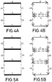
- FIGS. 5A and 5B illustrate a scanning pattern for creating an effective laser spot in accordance with another embodiment of the invention.
- FIGS. 6A-6C illustrate scanning patterns according to other embodiments of the invention.
- FIG. 7 schematically illustrates an effective spot in accordance with one possible embodiment of the invention.
- FIG. 8 schematically illustrates the configuration of an effective spot in accordance with an alternative embodiment of the invention.
- FIG. 9 illustrates an embodiment of the invention including means for displacing the scanner in relation to an object subjected to heat treatment.
- FIGS. 10A and 10B schematically illustrates two stages of heat treatment of a workpiece having a surface with curves or bends.
- FIG. 1A schematically illustrates a system in accordance with one possible embodiment of the invention, for heat treatment of a sheet metal object such as a pillar for a vehicle.
- the system comprises a laser equipment 1 for producing a laser beam 2 , and a scanner 3 including two mirrors or similar for two-dimensional scanning of the laser beam 2 in the horizontal (X-Y) plane.
- the equipment for producing a laser beam can, in some embodiments of the invention, be an equipment suitable for producing laser beams having a relatively high power content, such as 1 kW or more.
- a suitable device is the Ytterbium Laser System Model YLS-6000-CT, by IPG Photonics, with a nominal power of 6 kW.
- the system further comprises means (not shown in FIG. 1A ) for holding or supporting a workpiece 100 ; in the illustrated embodiment, the workpiece is for a vehicle body pillar, such as a so-called center pillar.
- the pillar or pillar workpiece can, for example, be a workpiece with very high hardness, obtained by hot-pressing a sheet metal template to give it the desired shape, followed by cooling the workpiece to produce quenching, as known in the art.
- the laser beam 2 is projected onto the workpiece in a region where it is desired to provide for reduced hardness, for example, to establish an area where deformation is preferably to take place in the case of an impact.
- the laser beam (and the primary laser spot that the beam projects on the building material) is repetitively scanned at a relatively high speed following a first scanning pattern (illustrated as a set of lines extending in parallel with the Y axis in FIG. 1A ), thereby creating an effective laser spot 21 , illustrated as a square in FIG. 1A .
- This effective laser spot 21 is displaced according to a second scanning pattern, for example, across the pillar; in FIG. 1A , an arrow indicates how the effective laser spot 21 can, for example, be displaced in parallel with the X axis of the system.
- the effective laser spot and its two-dimensional energy distribution can be dynamically adapted during the displacement of the effective laser spot along the second scanning pattern.
- the width of the effective laser spot (along the Y axis) can be adapted during its displacement across the workpiece, so that the width of the track subjected to heat treatment varies across the workpiece.
- other features of the effective laser spot can be adapted, so as to optimize the heat treatment, for example, the establishment of an area where the hardness is reduced so as to provide for a desired performance of the workpiece (for example, in the case of a structural component for a vehicle, so as to provide for a desired performance in terms of bending following an impact).
- FIGS. 1B and 1C schematically illustrate how the effective laser spot 21 can be adapted in width so as to carry out heat treatment of two tracks or segments 100 A and 100 B, respectively, of the workpiece 100 , these two tracks or segments having different widths and extending at two substantially different angles with regard to the laser source (the scanner).
- FIG. 1D schematically illustrates how the effective laser spot can be displaced along a segment 100 B of the workpiece having a width that varies along the track, whereby for example the width of the effective laser spot in the direction perpendicular to its displacement along the segment can be dynamically adapted during this displacement.
- FIG. 1E illustrates how the effective laser spot can be applied to provide for heat treatment of a track comprising two portions 100 A and 100 B of a pillar for a vehicle, in which said two portions are arranged at different angles in relation to the laser source and separated by a bend 100 C.
- the shape of the effective laser spot and the two-dimensional energy distribution within the effective laser spot can be adapted to, for example, the width of the area to be heated, the three-dimensional shape of said area to be heated (so as to, for example, take the bend 100 C into account), the orientation of different portions of said area in relation to the laser beam, etc.
- the system can include means 5 for dynamically adapting the size of the primary spot (for example, so as to modify the two-dimensional energy distribution and/or the size of the effective laser spot 21 ) and/or the focus of the laser beam along the optical axis.
- This makes it possible to control (such as to vary or maintain) the size of the primary laser spot while it is being displaced along the first scanning pattern, and/or while the effective laser spot 21 is being displaced in relation to the surface of the object.
- the optical focus can be adapted to keep the size of the primary spot constant while the primary spot is moving over the surface of the object (for example, to compensate for varying distances between the scanner and the position of the primary laser spot on the object being produced).
- means for dynamically adapting the focus of the laser beam can in some embodiments of the invention comprise a varioSCAN® focusing unit, obtainable from SCANLAB AG (www.scanlab.de).
- a scanning pattern comprising more than two lines arranged after each other in the direction of travelling of the effective laser spot (that is, the direction of the relative movement between the effective laser spot and the surface of the object), such as schematically illustrated in FIG. 2 , where the effective laser spot 21 is created by a plurality of parallel lines, extending in a direction perpendicular to the direction in which the effective laser spot is being displaced in relation to the surface of the object (this direction is indicated with an arrow in FIG. 2 ).
- the lines can have the same or different lengths, and the space between subsequent lines is one of the parameters that can be used to control the two-dimensional energy distribution.
- Such a scanning pattern can be created by repetitively scanning the primary laser spot in the direction perpendicular to the direction in which the effective laser spot is travelling, displacing the laser beam a small distance between each scanning step, so as to trace two, three or more parallel lines. Once the primary laser spot has completed the scanning pattern, it will return to its original position and carry out the scanning pattern once again.
- the frequency with which this occurs is preferably high, so as to avoid undesired temperature fluctuations within the effective laser spot 21 .
- the laser beam can be switched off while it is being displaced towards a new line to be followed, and/or between finishing the last line of the scanning pattern and returning to the first line of the scanning pattern.
- switching laser beams on and off requires time, and can slow down the scanning frequency.
- the time during which the laser beam is switched off is time that is lost in terms of efficient use of the laser for heating.
- FIGS. 3A and 3B illustrate one possible scanning pattern comprising three main lines a-c (illustrated as continuous lines) of the scanning pattern, and hatched lines illustrating the path which the laser spot follows between said lines.
- a-c illustrated as continuous lines
- hatched lines illustrating the path which the laser spot follows between said lines.
- the arrows schematically illustrate the way in which the primary laser spot travels over the surface.
- this scanning pattern involves a problem in that the heat distribution will not be symmetric. The same applies if, at the end of the pattern, when finishing the last line c (that is, from the head of the arrow of line c in FIG. 3B ), the laser beam returns vertically to line a.
- a more symmetrical energy distribution with regard to the axis parallel with the direction in which the effective laser spot is being displaced can be obtained with a scanning pattern as per FIGS. 4A and 4B , likewise comprising three parallel lines a-c interconnected by the lines d followed by the primary laser spot when moving between the three parallel lines.
- the laser beam from the beginning of the first line a, travels as follows: a-d 1 - b -d 2 - c -d 3 - b -d 4 .
- the primary laser spot travels along the intermediate line b twice as often as it travels through the first line and the last line: it travels along the intermediate line b twice for each time it travels along the first line a and the last line c.
- a completely symmetrical scanning pattern can be obtained, in relation to the axis parallel with the direction in which the effective laser spot is travelling.
- the energy distribution along this axis can be set by adjusting, for example, the distance between the lines a-c and the speed with which the laser beam travels along the lines.
- the energy distribution can be dynamically adapted without turning the laser beam on and off or without substantially modifying the power of the laser beam.
- the laser beam can travel with a higher speed along the intermediate line b than along the first line a and the last line c.
- the velocity of the primary laser spot along line b can be twice the speed of the primary laser spot along lines a and c.
- the velocity of the effective laser spot along lines d 1 -d 4 can also be substantially higher than the velocity of the effective laser spot along lines a and c.
- tailoring of the energy distribution can be achieved by adapting the distribution of the lines, such as the first, last and intermediate lines a-c, and by adapting the velocity of the primary laser spot along the different segments a-d (including d 1 -d 4 ) of the scanning pattern.
- the distribution of the segments and the velocity of the primary laser spot along the segments can be dynamically modified while the effective laser spot is being displaced in relation to the surface of the sheet metal object being heated, so as to adapt the two-dimensional energy distribution.
- the scanning pattern can be adapted by adding or deleting segments during the travelling of the effective laser spot.
- FIGS. 5A and 5B which includes an additional intermediate line b.
- the path followed by the primary laser spots a-d 1 - b -d 2 - b -d 3 - c -d 4 - b -d 5 - b -d 6 .
- FIGS. 6A-6C illustrate some alternative scanning patterns.
- the first scanning pattern can be a polygon such as a triangle (cf. FIG. 6A ), a rectangle (cf. FIG. 6B ), or an octagon (cf. FIG. 6C ).
- FIG. 7 schematically illustrates an effective spot 21 in accordance with one possible embodiment of the invention.
- the effective spot has a substantially rectangular configuration, with a height and a width.
- the arrow at the top of the figure illustrates the direction in which the effective spot 21 is being displaced in relation to the surface of the object.
- the effective spot 21 is obtained by scanning the primary spot 2 A projected by the beam, following a scanning pattern comprising five parallel lines, indicated by the rows of arrows within the effective spot 21 .
- a leading portion 21 A of the effective spot provides a certain pre-heating of the material
- a trailing portion 21 C is provided to slow down the cooling process.
- the main heating of the material takes place in the central portion 21 B of the effective spot 21 , that is, between the leading portion 21 A and the trailing portion 21 C.
- FIG. 8 schematically illustrates an effective laser spot 21 created by letting the primary spot follow a scanning pattern with six lines a, b, c wherein each line comprises five segments or pixels (a 1 , a 0 , b 1 , b 0 , c 1 ).
- the laser beam is on (segments or pixels a 1 , b 1 , c 1 ) or off (segments or pixels a 0 , b 0 ), in accordance with a desired energy distribution which can be varied dynamically during the process.
- the layout of FIG. 8 thus represents a 6 ⁇ 5 pixelization, and can easily be obtained with commercially available laser and scanning systems.
- a laser allowing for rapid on/off switching for example a fiber laser
- the number of lines that can be achieved for a certain scanning frequency such as 50 Hz or 100 Hz or more, will depend, inter alia, on the scanning means used.
- laser beam power states can be used, that is, different power levels between the maximum power and zero (or close to zero) power.
- the power states corresponding to different segments can be stored in a memory, and be dynamically modified during the process so as, for example, adapt the energy distribution to the three-dimensional configuration of the sheet metal object, to the desired width of a track to be heat treated, etc.
- This segmented or pixelized approach is very practical and allows the user to find appropriate energy distributions along and across the effective laser spot by trying different combinations of power states, that is, the power that the beam should have at different segments, until finding a combination that provides a desired result.
- the laser allows for rapid switching between different power states or levels, a high number of segments can be completed per second, allowing for a sufficiently high rate of repetition of the scanning pattern to avoid substantial temperature fluctuations between subsequent repetitions of the scanning pattern, while at the same time accommodating a reasonable amount of segments.
- a scanning pattern repetition frequency of 100 Hz can be combined with a scanning pattern having 10 segments.
- the scanning velocity can be adapted so that it is different in correspondence with different segments or pixels.
- FIG. 9 schematically illustrates how a processing head 200 , in accordance with one possible embodiment of the invention, can include a scanner 3 arranged to be displaced in relation to a sheet metal object 100 to be subjected to heat-treatment, in this case, a pillar for a vehicle.
- the processing head 200 is connected to actuators 300 through linkages 301 .
- the displacement is based on the parallel manipulator concept.
- any other suitable means of displacement of the processing head can be used, such as a robot arm, etc.
- it is the object being produced that is displaced in relation to the processing head.
- a combination of these two approaches can be used.
- the sheet metal workpiece 100 is supported by schematically illustrated support means 4 .
- FIGS. 10A and 10B schematically illustrate heat treatment of a workpiece 100 with a surface that features curves or bends, for example, after having been shaped in a press. This is often the case with sheet metal vehicle components.
- the arrow schematically illustrates how the energy beam 2 and the effective spot move in relation to the surface of the object, for example, by displacement of the scanner 3 in relation to the workpiece 100 , by displacing the workpiece 100 in relation to the scanner 3 , or a combination thereof.
- the effective spot arrives at a bent portion of the workpiece, there is a change in angle of incidence between the energy beam 2 and the surface of the object. To maintain the characteristics of the heating that is taking place, it can be desired to adapt the two-dimensional energy distribution of the effective spot.
- FIGS. 10A and 10B schematically illustrate heat treatment of a workpiece 100 with a surface that features curves or bends, for example, after having been shaped in a press. This is often the case with sheet metal vehicle components.
- the arrow schematically
- FIGS. 10A and 10B schematically illustrate how this can be achieved by, for example, modifying the scanning pattern, for example, by reducing the extension of the scanning pattern, so as to increase the power density in the area swept by the beam, perpendicular to the beam.
- FIGS. 10A and 10B schematically illustrate how the scanning pattern is modified by reducing the extension of the area swept by the energy beam, that is, reducing from the comparatively wide sweep 2 ′ of FIG. 10A to the more narrow sweep 2 ′′ of FIG. 10B .
- the distribution of the energy within the effective spot can be selected appropriately and adapted to the curvature of the surface within different portions of the effective spot, so that heating is carried out in an optimal manner.
- the two-dimensional energy distribution can be adapted to accommodate for variations in the surface being heated and of how the teachings of the invention can be used for the heat treatment of more or less complex surfaces, adapting the two-dimensional energy distribution within the effective spot and/or within the area swept by the energy beam in a plane perpendicular to the beam, by adapting for example the scanning pattern, the power of the energy beam during different segments of the scanning pattern, and/or the velocity of the primary spot along different segments of the scanning pattern. All of this can be achieved by software and without any need for complex and adaptable optics.
Landscapes
- Engineering & Computer Science (AREA)
- Chemical & Material Sciences (AREA)
- Physics & Mathematics (AREA)
- Optics & Photonics (AREA)
- Mechanical Engineering (AREA)
- Crystallography & Structural Chemistry (AREA)
- Materials Engineering (AREA)
- Metallurgy (AREA)
- Organic Chemistry (AREA)
- Thermal Sciences (AREA)
- Plasma & Fusion (AREA)
- Laser Beam Processing (AREA)
- Heat Treatment Of Strip Materials And Filament Materials (AREA)
- Heat Treatment Of Articles (AREA)
Applications Claiming Priority (4)
| Application Number | Priority Date | Filing Date | Title |
|---|---|---|---|
| EP15382122 | 2015-03-17 | ||
| EP15382122.8 | 2015-03-17 | ||
| EP15382122 | 2015-03-17 | ||
| PCT/EP2016/055612 WO2016146646A1 (en) | 2015-03-17 | 2016-03-15 | Method and system for heat treatment of sheet metal |
Publications (2)
| Publication Number | Publication Date |
|---|---|
| US20180071864A1 US20180071864A1 (en) | 2018-03-15 |
| US10864603B2 true US10864603B2 (en) | 2020-12-15 |
Family
ID=52811086
Family Applications (1)
| Application Number | Title | Priority Date | Filing Date |
|---|---|---|---|
| US15/559,384 Active 2037-04-28 US10864603B2 (en) | 2015-03-17 | 2016-03-15 | Method and system for heat treatment of sheet metal |
Country Status (8)
| Country | Link |
|---|---|
| US (1) | US10864603B2 (de) |
| EP (1) | EP3271486B1 (de) |
| CN (2) | CN114592118A (de) |
| BR (1) | BR112017019981B1 (de) |
| CA (1) | CA2979927C (de) |
| ES (1) | ES2761807T3 (de) |
| MX (1) | MX2017011964A (de) |
| WO (1) | WO2016146646A1 (de) |
Cited By (2)
| Publication number | Priority date | Publication date | Assignee | Title |
|---|---|---|---|---|
| US20220088706A1 (en) * | 2018-12-28 | 2022-03-24 | Etxe-Tar, S.A. | Method and system for heating using an energy beam |
| US11898214B2 (en) | 2012-09-06 | 2024-02-13 | Etxe-Tar, S.A. | Method and system for heat treating a workpiece |
Families Citing this family (6)
| Publication number | Priority date | Publication date | Assignee | Title |
|---|---|---|---|---|
| JP6535029B2 (ja) * | 2014-02-17 | 2019-06-26 | イェスタムプ・ハードテック・アクチエボラーグ | 細長い溶接部およびそうした溶接部を有するビーム |
| TWI734931B (zh) * | 2018-09-17 | 2021-08-01 | 鴻超光電科技股份有限公司 | 軸調光斑方法及其系統 |
| CN109321740B (zh) * | 2018-11-22 | 2024-02-13 | 沈阳航天新光集团有限公司 | 一种用于金属薄壁板材热处理的防变形工装 |
| EP3674029A1 (de) * | 2018-12-28 | 2020-07-01 | Etxe-Tar, S.A. | Verfahren und system zur erwärmung eines objekts unter verwendung eines energiestrahls |
| US11401565B2 (en) * | 2019-05-17 | 2022-08-02 | Fca Us Llc | Sheet metal forming die laser surface hardening process |
| EP3983567A1 (de) * | 2019-06-12 | 2022-04-20 | Etxe-Tar, S.A. | Verfahren und system zur erwärmung eines energiestrahls |
Citations (82)
| Publication number | Priority date | Publication date | Assignee | Title |
|---|---|---|---|---|
| DE256275C (de) | ||||
| DE256274C (de) | ||||
| DE242358C (de) | 1900-01-01 | |||
| DE2018793A1 (en) | 1970-04-20 | 1971-11-04 | Steigerwald Strahltech | Electron beam tool hardening |
| US3848104A (en) | 1973-04-09 | 1974-11-12 | Avco Everett Res Lab Inc | Apparatus for heat treating a surface |
| US3952180A (en) | 1974-12-04 | 1976-04-20 | Avco Everett Research Laboratory, Inc. | Cladding |
| US4313771A (en) | 1980-02-29 | 1982-02-02 | Xerox Corporation | Laser hardening of steel work pieces |
| JPS5785931A (en) | 1980-11-18 | 1982-05-28 | Komatsu Ltd | Heat treatment of crank shaft |
| US4456811A (en) * | 1982-06-21 | 1984-06-26 | Avco Everett Research Laboratory, Inc. | Method of and apparatus for heat treating axisymmetric surfaces with an annular laser beam |
| JPS59164817U (ja) | 1983-04-21 | 1984-11-05 | トヨタ自動車株式会社 | クランクシヤフト |
| EP0060257B1 (de) | 1980-09-11 | 1985-10-02 | Sciaky Bros., Inc. | Verfahren zum oberflächenhärten von nocken |
| JPS627821A (ja) | 1985-07-02 | 1987-01-14 | Honda Motor Co Ltd | クランクシヤフト用レ−ザ焼入装置 |
| US4797532A (en) | 1986-03-26 | 1989-01-10 | Maiorov Vladimir S | Apparatus for laser treatment of materials |
| DE3905551A1 (de) | 1989-02-23 | 1990-08-30 | Gartzen Johannes | Verfahren und vorrichtung zur behandlung von oberflaechen mittels laserstrahl |
| JPH03122212A (ja) | 1989-10-06 | 1991-05-24 | Toyota Motor Corp | レーザ焼入れ方法 |
| DE4018355A1 (de) | 1990-06-08 | 1992-01-09 | Fraunhofer Ges Forschung | Verfahren zur oberflaechenbehandlung von werkstuecken mit laserstrahlung |
| JPH04141522A (ja) | 1990-09-29 | 1992-05-15 | Hino Motors Ltd | クランクシャフトの油穴部の焼入れ方法 |
| DE4123577A1 (de) | 1991-07-13 | 1993-01-21 | Dieter Dr Pollack | Verfahren zur laserhaertung von bauteilen |
| DE4126351A1 (de) | 1991-08-09 | 1993-02-11 | Fraunhofer Ges Forschung | Verfahren zum bearbeiten von werkstueckoberflaechen mit laserstrahlung |
| DE4142216A1 (de) | 1991-12-20 | 1993-07-08 | Volkswagen Ag | Verfahren und anordnung zur erhoehung der torsionswechselfestigkeit eines eine nut aufweisenden bauteils |
| DE4241592C1 (de) | 1992-12-10 | 1993-11-04 | Daimler Benz Ag | Anordnung zur veraenderung der geometrischen gestalt eines lichtbuendels mit spiegeln |
| DE4209938C1 (de) | 1992-03-27 | 1993-12-02 | Mauser Werke Oberndorf | Verfahren zum Umschmelzen einer Werkstückoberfläche |
| JPH06226479A (ja) | 1993-02-02 | 1994-08-16 | Honda Motor Co Ltd | 集合ブランク部材およびその製造方法 |
| US5446258A (en) | 1991-04-12 | 1995-08-29 | Mli Lasers | Process for remelting metal surfaces using a laser |
| EP0698800A1 (de) | 1994-08-25 | 1996-02-28 | Fraunhofer-Gesellschaft Zur Förderung Der Angewandten Forschung E.V. | Verfahren zur Steuerung der Laserstrahlintensitätsverteilung für die Bearbeitung von Bauteiloberflächen |
| US5705788A (en) | 1993-05-19 | 1998-01-06 | Fraunhofer-Gesellschaft Zur Forderung Der Angewandten Forschung E.V. | Process for treatment of materials with diode radiation |
| US5786924A (en) * | 1995-09-13 | 1998-07-28 | Reliant Technologies, Inc. | Method and apparatus for treating a surface with a scanning laser beam having an improved intensity cross-section |
| EP0965516A1 (de) | 1998-06-15 | 1999-12-22 | ROCKINGER Spezialfabrik für Anhängerkupplungen GmbH & Co. | Zugfahrzeug mit gehärteter Sattelplatte, Verfahren zum Härten einer Sattelplatte für ein Zugfahrzeug |
| DE19853733C1 (de) | 1998-11-23 | 2000-02-24 | Fraunhofer Ges Forschung | Verfahren zur lokal gezielten Wärmebehandlung von Werkstückoberflächen |
| US20020069945A1 (en) | 1999-05-12 | 2002-06-13 | Wolfgang Streubel | Method for manufacturing structural parts for automobile body construction |
| GB2370584A (en) | 2000-10-06 | 2002-07-03 | Perkins Engines Co Ltd | Hardening of crankshaft bearing surfaces |
| US20020096503A1 (en) | 2001-01-25 | 2002-07-25 | The Regents Of The University Of California | Laser peening of components of thin cross-section |
| FR2825375A1 (fr) | 2001-05-31 | 2002-12-06 | Renault | Procede et dispositif de renforcement localise d'une tole de structure |
| US20030080098A1 (en) | 2001-10-30 | 2003-05-01 | Tsunehiko Yamazaki | Method of controlling hardening with laser beam and laser beam hardening device |
| US20030132208A1 (en) | 2002-01-11 | 2003-07-17 | Cutler Donald R. | Simulated laser spot enlargement |
| JP2003231914A (ja) | 2002-02-13 | 2003-08-19 | Toyota Motor Corp | レーザ焼入れ方法 |
| JP2004084931A (ja) | 2002-06-27 | 2004-03-18 | Nissan Motor Co Ltd | クランクシャフトおよびその製造方法 |
| US20040108306A1 (en) | 2002-12-06 | 2004-06-10 | Michael Wiezbowski | Laser heat treatment of crankshaft fillets |
| US20040244529A1 (en) | 2003-06-04 | 2004-12-09 | Georg Toplack | Workpiece, in particular a crankshaft |
| US20050237895A1 (en) | 2004-04-23 | 2005-10-27 | Semiconductor Energy Laboratory Co., Ltd. | Laser irradiation apparatus and method for manufacturing semiconductor device |
| DE102004023579A1 (de) | 2004-05-13 | 2005-12-15 | Adam Opel Ag | Verfahren zur Wärmebehandlung eines Fügeteils aus hochfestem Stahl |
| DE102005005141B3 (de) | 2005-02-04 | 2006-06-08 | Daimlerchrysler Ag | Verfahren zum Härten von rotationssymmetrischen Bauteilen |
| US7070228B2 (en) | 2001-11-27 | 2006-07-04 | Kikuchi Co., Ltd. | Press molding and its high frequency quenching method and its high frequency quenching system |
| EP0822027B2 (de) | 1996-08-03 | 2006-11-15 | INPRO Innovationsgesellschaft für fortgeschrittene Produktionssysteme in der Fahrzeugindustrie mbH | Verfahren zum Härten von Werkstückoberflächen mittels Strahlen, insbesondere mittels Laserstrahlen, und Vorrichtung zur Durchführung des Verfahrens |
| DE102006031273A1 (de) | 2006-07-06 | 2008-01-10 | Daimlerchrysler Ag | Verfahren zum partiellen Härten der Oberfläche eines Bauteils |
| US20080053384A1 (en) | 2006-08-23 | 2008-03-06 | Nuvonyx, Inc. | Piston having diode laser hardened primary compression ring groove and method of making the same |
| JP2008202438A (ja) | 2007-02-17 | 2008-09-04 | Hosei Brake Ind Ltd | エンジン用可変バルブタイミング機構 |
| EP1972694A2 (de) | 2007-03-23 | 2008-09-24 | Yamaha Hatsudoki Kabushiki Kaisha | Kurbelwelle, Verbrennungsmotor, Transportvorrichtung und Herstellungsverfahren für die Kurbelwelle |
| US20090032510A1 (en) | 2005-06-01 | 2009-02-05 | Phoeton Corp. | Laser Processing Apparatus and Laser Processing Method |
| DE102008020794A1 (de) | 2008-02-04 | 2009-08-06 | Volkswagen Ag | Verfahren zum Laserhärten von Stahlwerkstücken und dazugehörige Laserhärteanlage |
| US20090272464A1 (en) | 2006-10-23 | 2009-11-05 | Nippon Steel Corporation | Grain-Oriented Electrical Sheet Superior in Watt Loss |
| US20100086803A1 (en) | 2008-09-15 | 2010-04-08 | Thyssenkrupp Steel Ag | Hot-formed profile |
| US20100126642A1 (en) | 2006-10-27 | 2010-05-27 | Berndt Brenner | Process and apparatus for hardening the surface layer of components having a complicated shape |
| DE10118291C5 (de) | 2001-04-12 | 2010-07-22 | Sms Elotherm Gmbh | Vorrichtung zum Laser-Belichten einer Fläche von metalischen Werkstücken und deren Verwendung |
| EP2309126A1 (de) | 2008-07-16 | 2011-04-13 | Kawasaki Jukogyo Kabushiki Kaisha | Hydraulische taumelscheibenrotationsmaschine |
| DE102009057390A1 (de) | 2009-12-08 | 2011-05-19 | Daimler Ag | Verfahren zum Härten eines Bauteils sowie Bauteil |
| DE10261710B4 (de) | 2002-12-30 | 2011-07-21 | Volkswagen AG, 38440 | Verfahren zur Oberflächenbehandlung einer Welle |
| WO2012025171A1 (de) | 2010-08-24 | 2012-03-01 | Volkswagen Aktiengesellschaft | Profilbauteil und verfahren zur herstellung eines profilbauteils |
| DE102010048645A1 (de) | 2010-10-15 | 2012-04-19 | Daimler Ag | Vorrichtung und Verfahren zur Wärmebehandlung einer Bauteiloberfläche |
| DE102010049330A1 (de) | 2010-10-22 | 2012-04-26 | Sitech Sitztechnik Gmbh | Schienenprofil mit gezielt eingestellten laserverfestigten Bereichen |
| JP2012144768A (ja) | 2011-01-11 | 2012-08-02 | Fuji Heavy Ind Ltd | クランクシャフトへの焼入方法及びそのクランクシャフト |
| DE102011118285A1 (de) | 2011-11-10 | 2012-08-09 | Daimler Ag | Verfahren zur Herstellung eines Kraftwagenbauteils und Kraftwagenbauteil |
| US20120237387A1 (en) | 2009-09-21 | 2012-09-20 | Aperam | Stainless steel having local variations in mechanical resistance |
| US8272681B2 (en) | 2007-05-26 | 2012-09-25 | Ulrich Schoof | Process for producing a locally hardened profile component, locally hardened profile component and use of a locally hardened profile component |
| WO2012156084A1 (de) | 2011-05-19 | 2012-11-22 | Volkswagen Aktiengesellschaft | Wärmebehandlung von härtbaren blechbauteilen |
| US20120312159A1 (en) | 2011-06-10 | 2012-12-13 | Caterpillar Inc. | Machine component with a cavitation resistant covering |
| EP2541093A1 (de) | 2010-08-26 | 2013-01-02 | Nippon Steel & Sumitomo Metal Corporation | Stossdämpfendes element |
| EP2561946A1 (de) | 2010-04-19 | 2013-02-27 | Autotech Engineering A.I.E. | Bauteil eines fahrzeuges und herstellungsverfahren dafür |
| EP2565489A1 (de) | 2010-08-26 | 2013-03-06 | Nippon Steel & Sumitomo Metal Corporation | Stossdämpfungselement |
| EP2570205A1 (de) | 2011-09-15 | 2013-03-20 | Dieter Uschkoreit | Werkzeug zum Warmumformen und Härten einer Blechplatine |
| DE102011054866A1 (de) | 2011-10-27 | 2013-05-02 | Benteler Automobiltechnik Gmbh | Verfahren zur Herstellung eines warmumgeformten und pressgehärteten Kraftfahrzeugkarosseriebauteils sowie Kraftfahrzeugkarosseriebauteil |
| US8480163B2 (en) | 2008-07-14 | 2013-07-09 | Toyota Jidosha Kabushiki Kaisha | Pillar structure of vehicle and method for manufacturing the same |
| CN103215411A (zh) | 2013-02-06 | 2013-07-24 | 武汉新瑞达激光工程有限责任公司 | 一种激光淬火方法及装置 |
| CN103290176A (zh) | 2013-05-20 | 2013-09-11 | 华中科技大学 | 一种多次辐照激光淬火方法及装置 |
| US8555507B2 (en) | 2009-07-21 | 2013-10-15 | Sungwoo Hitech Co., Ltd. | Method for fabricating a member of a vehicle |
| CN103484653A (zh) | 2013-09-04 | 2014-01-01 | 中国航空工业集团公司北京航空制造工程研究所 | 环形激光冲击强化紧固孔的装置和方法 |
| WO2014037281A2 (en) | 2012-09-06 | 2014-03-13 | Etxe-Tar, S.A. | Method and system for laser hardening of a surface of a workpiece |
| DE102013008494A1 (de) | 2013-05-18 | 2014-03-27 | Daimler Ag | Verfahren zur Herstellung eines metallischen Blechbauteils und Pressenlinie |
| US8847126B2 (en) | 2008-08-08 | 2014-09-30 | Aisin Takaoka Co., Ltd. | Heating device and heating method |
| US20150321286A1 (en) * | 2012-11-30 | 2015-11-12 | Directphotonics Industries | Device and method for laser material machining |
| WO2015179747A1 (en) * | 2014-05-23 | 2015-11-26 | Johnson Controls Technology Company | In-process laser hardening/forming of vehicle seat structures and components |
| US20160312328A1 (en) * | 2013-12-13 | 2016-10-27 | Tata Steel Limited | Multi-Track Laser Surface Hardening of Low Carbon Cold Rolled Closely Annealed (CRCA) Grades of Steels |
-
2016
- 2016-03-15 WO PCT/EP2016/055612 patent/WO2016146646A1/en active Application Filing
- 2016-03-15 CN CN202210277559.3A patent/CN114592118A/zh active Pending
- 2016-03-15 EP EP16714258.7A patent/EP3271486B1/de active Active
- 2016-03-15 MX MX2017011964A patent/MX2017011964A/es unknown
- 2016-03-15 US US15/559,384 patent/US10864603B2/en active Active
- 2016-03-15 CA CA2979927A patent/CA2979927C/en active Active
- 2016-03-15 BR BR112017019981-5A patent/BR112017019981B1/pt active IP Right Grant
- 2016-03-15 CN CN201680024356.6A patent/CN107980067A/zh active Pending
- 2016-03-15 ES ES16714258T patent/ES2761807T3/es active Active
Patent Citations (87)
| Publication number | Priority date | Publication date | Assignee | Title |
|---|---|---|---|---|
| DE256275C (de) | ||||
| DE256274C (de) | ||||
| DE242358C (de) | 1900-01-01 | |||
| DE2018793A1 (en) | 1970-04-20 | 1971-11-04 | Steigerwald Strahltech | Electron beam tool hardening |
| US3848104A (en) | 1973-04-09 | 1974-11-12 | Avco Everett Res Lab Inc | Apparatus for heat treating a surface |
| US3952180A (en) | 1974-12-04 | 1976-04-20 | Avco Everett Research Laboratory, Inc. | Cladding |
| US4313771A (en) | 1980-02-29 | 1982-02-02 | Xerox Corporation | Laser hardening of steel work pieces |
| EP0060257B1 (de) | 1980-09-11 | 1985-10-02 | Sciaky Bros., Inc. | Verfahren zum oberflächenhärten von nocken |
| JPS5785931A (en) | 1980-11-18 | 1982-05-28 | Komatsu Ltd | Heat treatment of crank shaft |
| US4456811A (en) * | 1982-06-21 | 1984-06-26 | Avco Everett Research Laboratory, Inc. | Method of and apparatus for heat treating axisymmetric surfaces with an annular laser beam |
| JPS59164817U (ja) | 1983-04-21 | 1984-11-05 | トヨタ自動車株式会社 | クランクシヤフト |
| JPS627821A (ja) | 1985-07-02 | 1987-01-14 | Honda Motor Co Ltd | クランクシヤフト用レ−ザ焼入装置 |
| US4797532A (en) | 1986-03-26 | 1989-01-10 | Maiorov Vladimir S | Apparatus for laser treatment of materials |
| DE3905551A1 (de) | 1989-02-23 | 1990-08-30 | Gartzen Johannes | Verfahren und vorrichtung zur behandlung von oberflaechen mittels laserstrahl |
| JPH03122212A (ja) | 1989-10-06 | 1991-05-24 | Toyota Motor Corp | レーザ焼入れ方法 |
| DE4018355A1 (de) | 1990-06-08 | 1992-01-09 | Fraunhofer Ges Forschung | Verfahren zur oberflaechenbehandlung von werkstuecken mit laserstrahlung |
| JPH04141522A (ja) | 1990-09-29 | 1992-05-15 | Hino Motors Ltd | クランクシャフトの油穴部の焼入れ方法 |
| US5446258A (en) | 1991-04-12 | 1995-08-29 | Mli Lasers | Process for remelting metal surfaces using a laser |
| DE4123577A1 (de) | 1991-07-13 | 1993-01-21 | Dieter Dr Pollack | Verfahren zur laserhaertung von bauteilen |
| DE4126351A1 (de) | 1991-08-09 | 1993-02-11 | Fraunhofer Ges Forschung | Verfahren zum bearbeiten von werkstueckoberflaechen mit laserstrahlung |
| DE4142216A1 (de) | 1991-12-20 | 1993-07-08 | Volkswagen Ag | Verfahren und anordnung zur erhoehung der torsionswechselfestigkeit eines eine nut aufweisenden bauteils |
| DE4209938C1 (de) | 1992-03-27 | 1993-12-02 | Mauser Werke Oberndorf | Verfahren zum Umschmelzen einer Werkstückoberfläche |
| DE4241592C1 (de) | 1992-12-10 | 1993-11-04 | Daimler Benz Ag | Anordnung zur veraenderung der geometrischen gestalt eines lichtbuendels mit spiegeln |
| JPH06226479A (ja) | 1993-02-02 | 1994-08-16 | Honda Motor Co Ltd | 集合ブランク部材およびその製造方法 |
| US5705788A (en) | 1993-05-19 | 1998-01-06 | Fraunhofer-Gesellschaft Zur Forderung Der Angewandten Forschung E.V. | Process for treatment of materials with diode radiation |
| DE4430220C2 (de) | 1994-08-25 | 1998-01-22 | Fraunhofer Ges Forschung | Verfahren zur Steuerung der Laserstrahlintensitätsverteilung auf der Oberfläche zu bearbeitender Bauteile |
| EP0698800A1 (de) | 1994-08-25 | 1996-02-28 | Fraunhofer-Gesellschaft Zur Förderung Der Angewandten Forschung E.V. | Verfahren zur Steuerung der Laserstrahlintensitätsverteilung für die Bearbeitung von Bauteiloberflächen |
| US5786924A (en) * | 1995-09-13 | 1998-07-28 | Reliant Technologies, Inc. | Method and apparatus for treating a surface with a scanning laser beam having an improved intensity cross-section |
| EP0822027B2 (de) | 1996-08-03 | 2006-11-15 | INPRO Innovationsgesellschaft für fortgeschrittene Produktionssysteme in der Fahrzeugindustrie mbH | Verfahren zum Härten von Werkstückoberflächen mittels Strahlen, insbesondere mittels Laserstrahlen, und Vorrichtung zur Durchführung des Verfahrens |
| EP0965516A1 (de) | 1998-06-15 | 1999-12-22 | ROCKINGER Spezialfabrik für Anhängerkupplungen GmbH & Co. | Zugfahrzeug mit gehärteter Sattelplatte, Verfahren zum Härten einer Sattelplatte für ein Zugfahrzeug |
| DE19853733C1 (de) | 1998-11-23 | 2000-02-24 | Fraunhofer Ges Forschung | Verfahren zur lokal gezielten Wärmebehandlung von Werkstückoberflächen |
| US20020069945A1 (en) | 1999-05-12 | 2002-06-13 | Wolfgang Streubel | Method for manufacturing structural parts for automobile body construction |
| GB2370584A (en) | 2000-10-06 | 2002-07-03 | Perkins Engines Co Ltd | Hardening of crankshaft bearing surfaces |
| US20020096503A1 (en) | 2001-01-25 | 2002-07-25 | The Regents Of The University Of California | Laser peening of components of thin cross-section |
| DE10118291C5 (de) | 2001-04-12 | 2010-07-22 | Sms Elotherm Gmbh | Vorrichtung zum Laser-Belichten einer Fläche von metalischen Werkstücken und deren Verwendung |
| FR2825375A1 (fr) | 2001-05-31 | 2002-12-06 | Renault | Procede et dispositif de renforcement localise d'une tole de structure |
| US20030080098A1 (en) | 2001-10-30 | 2003-05-01 | Tsunehiko Yamazaki | Method of controlling hardening with laser beam and laser beam hardening device |
| EP1308525A2 (de) | 2001-10-30 | 2003-05-07 | Yamazaki Mazak Kabushiki Kaisha | Verfahren zum kontrollierten Laserstrahlhärten und Laserstrahlhärtevorrichtung |
| US7070228B2 (en) | 2001-11-27 | 2006-07-04 | Kikuchi Co., Ltd. | Press molding and its high frequency quenching method and its high frequency quenching system |
| US20030132208A1 (en) | 2002-01-11 | 2003-07-17 | Cutler Donald R. | Simulated laser spot enlargement |
| JP2003231914A (ja) | 2002-02-13 | 2003-08-19 | Toyota Motor Corp | レーザ焼入れ方法 |
| JP2004084931A (ja) | 2002-06-27 | 2004-03-18 | Nissan Motor Co Ltd | クランクシャフトおよびその製造方法 |
| US20040108306A1 (en) | 2002-12-06 | 2004-06-10 | Michael Wiezbowski | Laser heat treatment of crankshaft fillets |
| DE10261710B4 (de) | 2002-12-30 | 2011-07-21 | Volkswagen AG, 38440 | Verfahren zur Oberflächenbehandlung einer Welle |
| US20040244529A1 (en) | 2003-06-04 | 2004-12-09 | Georg Toplack | Workpiece, in particular a crankshaft |
| US20050237895A1 (en) | 2004-04-23 | 2005-10-27 | Semiconductor Energy Laboratory Co., Ltd. | Laser irradiation apparatus and method for manufacturing semiconductor device |
| DE102004023579A1 (de) | 2004-05-13 | 2005-12-15 | Adam Opel Ag | Verfahren zur Wärmebehandlung eines Fügeteils aus hochfestem Stahl |
| DE102005005141B3 (de) | 2005-02-04 | 2006-06-08 | Daimlerchrysler Ag | Verfahren zum Härten von rotationssymmetrischen Bauteilen |
| US20090032510A1 (en) | 2005-06-01 | 2009-02-05 | Phoeton Corp. | Laser Processing Apparatus and Laser Processing Method |
| DE102006031273A1 (de) | 2006-07-06 | 2008-01-10 | Daimlerchrysler Ag | Verfahren zum partiellen Härten der Oberfläche eines Bauteils |
| US20080053384A1 (en) | 2006-08-23 | 2008-03-06 | Nuvonyx, Inc. | Piston having diode laser hardened primary compression ring groove and method of making the same |
| US20090272464A1 (en) | 2006-10-23 | 2009-11-05 | Nippon Steel Corporation | Grain-Oriented Electrical Sheet Superior in Watt Loss |
| US20100126642A1 (en) | 2006-10-27 | 2010-05-27 | Berndt Brenner | Process and apparatus for hardening the surface layer of components having a complicated shape |
| JP2008202438A (ja) | 2007-02-17 | 2008-09-04 | Hosei Brake Ind Ltd | エンジン用可変バルブタイミング機構 |
| US20080229877A1 (en) | 2007-03-23 | 2008-09-25 | Yamaha Hatsudoki Kabushiki Kaisha | Crankshaft, internal combustion engine, transportation apparatus, and production method for crankshaft |
| EP1972694A2 (de) | 2007-03-23 | 2008-09-24 | Yamaha Hatsudoki Kabushiki Kaisha | Kurbelwelle, Verbrennungsmotor, Transportvorrichtung und Herstellungsverfahren für die Kurbelwelle |
| US8272681B2 (en) | 2007-05-26 | 2012-09-25 | Ulrich Schoof | Process for producing a locally hardened profile component, locally hardened profile component and use of a locally hardened profile component |
| DE102008020794A1 (de) | 2008-02-04 | 2009-08-06 | Volkswagen Ag | Verfahren zum Laserhärten von Stahlwerkstücken und dazugehörige Laserhärteanlage |
| US8480163B2 (en) | 2008-07-14 | 2013-07-09 | Toyota Jidosha Kabushiki Kaisha | Pillar structure of vehicle and method for manufacturing the same |
| EP2309126A1 (de) | 2008-07-16 | 2011-04-13 | Kawasaki Jukogyo Kabushiki Kaisha | Hydraulische taumelscheibenrotationsmaschine |
| US8847126B2 (en) | 2008-08-08 | 2014-09-30 | Aisin Takaoka Co., Ltd. | Heating device and heating method |
| US20100086803A1 (en) | 2008-09-15 | 2010-04-08 | Thyssenkrupp Steel Ag | Hot-formed profile |
| US8555507B2 (en) | 2009-07-21 | 2013-10-15 | Sungwoo Hitech Co., Ltd. | Method for fabricating a member of a vehicle |
| US20120237387A1 (en) | 2009-09-21 | 2012-09-20 | Aperam | Stainless steel having local variations in mechanical resistance |
| DE102009057390A1 (de) | 2009-12-08 | 2011-05-19 | Daimler Ag | Verfahren zum Härten eines Bauteils sowie Bauteil |
| EP2561946A1 (de) | 2010-04-19 | 2013-02-27 | Autotech Engineering A.I.E. | Bauteil eines fahrzeuges und herstellungsverfahren dafür |
| WO2012025171A1 (de) | 2010-08-24 | 2012-03-01 | Volkswagen Aktiengesellschaft | Profilbauteil und verfahren zur herstellung eines profilbauteils |
| EP2541093A1 (de) | 2010-08-26 | 2013-01-02 | Nippon Steel & Sumitomo Metal Corporation | Stossdämpfendes element |
| EP2565489A1 (de) | 2010-08-26 | 2013-03-06 | Nippon Steel & Sumitomo Metal Corporation | Stossdämpfungselement |
| DE102010048645A1 (de) | 2010-10-15 | 2012-04-19 | Daimler Ag | Vorrichtung und Verfahren zur Wärmebehandlung einer Bauteiloberfläche |
| DE102010049330A1 (de) | 2010-10-22 | 2012-04-26 | Sitech Sitztechnik Gmbh | Schienenprofil mit gezielt eingestellten laserverfestigten Bereichen |
| JP2012144768A (ja) | 2011-01-11 | 2012-08-02 | Fuji Heavy Ind Ltd | クランクシャフトへの焼入方法及びそのクランクシャフト |
| WO2012156084A1 (de) | 2011-05-19 | 2012-11-22 | Volkswagen Aktiengesellschaft | Wärmebehandlung von härtbaren blechbauteilen |
| US20120312159A1 (en) | 2011-06-10 | 2012-12-13 | Caterpillar Inc. | Machine component with a cavitation resistant covering |
| EP2570205A1 (de) | 2011-09-15 | 2013-03-20 | Dieter Uschkoreit | Werkzeug zum Warmumformen und Härten einer Blechplatine |
| DE102011054866A1 (de) | 2011-10-27 | 2013-05-02 | Benteler Automobiltechnik Gmbh | Verfahren zur Herstellung eines warmumgeformten und pressgehärteten Kraftfahrzeugkarosseriebauteils sowie Kraftfahrzeugkarosseriebauteil |
| DE102011118285A1 (de) | 2011-11-10 | 2012-08-09 | Daimler Ag | Verfahren zur Herstellung eines Kraftwagenbauteils und Kraftwagenbauteil |
| US20190002997A1 (en) | 2012-09-06 | 2019-01-03 | Etxe-Tar, S.A. | Method and system for laser hardening of a surface of a workpiece |
| WO2014037281A2 (en) | 2012-09-06 | 2014-03-13 | Etxe-Tar, S.A. | Method and system for laser hardening of a surface of a workpiece |
| US20150321286A1 (en) * | 2012-11-30 | 2015-11-12 | Directphotonics Industries | Device and method for laser material machining |
| CN103215411A (zh) | 2013-02-06 | 2013-07-24 | 武汉新瑞达激光工程有限责任公司 | 一种激光淬火方法及装置 |
| US20160076115A1 (en) | 2013-02-06 | 2016-03-17 | Wuhan NRD Laser Engineering Co., Ltd. | Method and apparatus for laser quenching |
| DE102013008494A1 (de) | 2013-05-18 | 2014-03-27 | Daimler Ag | Verfahren zur Herstellung eines metallischen Blechbauteils und Pressenlinie |
| CN103290176A (zh) | 2013-05-20 | 2013-09-11 | 华中科技大学 | 一种多次辐照激光淬火方法及装置 |
| CN103484653A (zh) | 2013-09-04 | 2014-01-01 | 中国航空工业集团公司北京航空制造工程研究所 | 环形激光冲击强化紧固孔的装置和方法 |
| US20160312328A1 (en) * | 2013-12-13 | 2016-10-27 | Tata Steel Limited | Multi-Track Laser Surface Hardening of Low Carbon Cold Rolled Closely Annealed (CRCA) Grades of Steels |
| WO2015179747A1 (en) * | 2014-05-23 | 2015-11-26 | Johnson Controls Technology Company | In-process laser hardening/forming of vehicle seat structures and components |
Non-Patent Citations (30)
| Title |
|---|
| CN Office Action dated Dec. 3, 2018 re: Application No. 201680024356.6, pp. 1-20. |
| CN Office Action dated Nov. 6, 2017 re: Application No. 201580013179.7; pp. 1-23. |
| Dr. Steffen Bonβ, "System components create reliable processes", Mar. 27-28, 2012, pp. 1-48. |
| European Intention to Grant for European Application No. 16714258.7, Aplication Filing Date Mar. 15, 2016, dated Feb. 26, 2019, 86 pages. |
| European Search Report for European Application No. 15382122.8; Application Filing Date: Mar. 17, 2015; dated Jun. 9, 2015; 5 pages. |
| F. Vollertsen, et al., "State of the art of Laser Hardening and Cladding", Proceedings of the Third International WLT-Conference on Lasers in Manufacturing 2005, Munich, Jun. 2005. |
| H. Koehler et al. "Laser reconditioning of crankshafts: From lab to application", ScienceDirect, Physics Procedia, 2010, vol. 5, pp. 387-397. |
| Hideki Hagino, et al, "Design of a computer-generated hologram for obtaining a uniform hardened profile by laser transformation hardening with a high-power diode laser", Precision Engineering 34 (2010) 446-452. |
| International Preliminary Report on Patentability for International Application No. PCT/EP2016/055612; International Filing Date Mar. 15, 2016; dated Sep. 19, 2017; 6 pages. |
| International Search Report dated Jun. 6, 2016 re: Application No. PCT/EP2016/055612; pp. 1-3. |
| Klaus Müller "Metallurgical qualification of edge layer hardening with laser beam", Herbert Utz Publication, Science Munich, 1999, pp. 1-8. |
| Klocke, et al., "Flexible scanner-based laser surface treatment", Science Direct, Physics Procedia 5 (2010) 467-475. |
| M. Seifert, et al., "High Power Diode Laser Beam Scanning in Multi-Kilowatt Range", Proceedings of the 23rd International Congress on Applications of Lasers and Electro-Optics 2004. |
| Marko Seifert et al. "High-Speed and Camera Based Temperature Measurement and Control for High Power Laser Scanning Systems", Proceedings of the 2nd Pacific International Conference on Application of Laswers and Optics, 2006, pp. 1-6. |
| Marko Seifert, "The range of process variants for laser heat treatment with precises temperature control", 9th Workshop Industrial Application of High-Power Diode Lasers, Mar. 27-28, 2012, pp. 1-72. |
| Markus Seifert et al. "Dynamic beam shaping for high-power diode lasers up to 4kW", Fraunhofer IWS Dresden Oct. 21-22, 2004, pp. 1-44. |
| Program 9th Workshop "Industrial applications of high-power diode lasers", Mar. 27-28, 2012, pp. 1-40. |
| S M Shariff, "Laser Surface Hardening of Crankshaft", International Advanced research center for powder metallurgy and new materials (ARCI), SAE 2009-28-0053 Copyright 2009. |
| S. Bonβ et al., "Novel machine system for simultaneous heat treatment with dynamic beam shaping", Conference on Laser Materials Processing in the Nordic Countries (NOLAMP), 2007, pp. 1-10. |
| S. Bonβ, "Laser-beam hardening-Integration into production makes proceses more streamlined", Z. Werkst. Warmebeh. Fertigung 63, 2008, vol. 3. |
| S. Bonβ, "Laser-beam hardening—Integration into production makes proceses more streamlined", Z. Werkst. Warmebeh. Fertigung 63, 2008, vol. 3. |
| Seifert, et al., "High Power Diode Laser Beam Scanning in Multi-Kilowatt Range", Proceedings of the 23rd International Congress on Applications of Laysers and Electro-Optics 2004, 6 pages. |
| Shakeel SAFDAR et al., "An Analysis of the Effect of Laser Beam Geometry on Laser Transformation Hardening", Journal of Manufacturing Science and Engineering, Aug. 2006, vol. 128, pp. 659-667. |
| Stefan Jahn "Applications of laser hardening in series production of crankshafts", Mar. 28, 2012, pp. 1-76. |
| Steffen Bonβ "Laser-beam hardening-Integration into production makes processes streamlined", Automobile Industry Laser Hardening, 2007, vol. 6, No. 9, pp. 1-8. |
| Steffen Bonβ "Laser-beam hardening—Integration into production makes processes streamlined", Automobile Industry Laser Hardening, 2007, vol. 6, No. 9, pp. 1-8. |
| Steffen Bonβ et al. "Integrated Heat Treatment Comparison of Different Machine Concepts", Fraunhofer IWS Dresden, Institut Werkstoff-und Strahltechnik, ICALEO 2006, pp. 1-34. |
| Steffen Bonβ et al., "Integrated Laser Beam Hardening in Turning Machines for Process Chain Reduction", Rexroth Bosch Group, 2008, pp. 1-10. |
| Wikipedia "Full width at half maximum", 2018, pp. 1-2. |
| Written Opinion dated Jun. 6, 2016 re: Application No. PCT/EP2016/055612; pp. 1-5. |
Cited By (2)
| Publication number | Priority date | Publication date | Assignee | Title |
|---|---|---|---|---|
| US11898214B2 (en) | 2012-09-06 | 2024-02-13 | Etxe-Tar, S.A. | Method and system for heat treating a workpiece |
| US20220088706A1 (en) * | 2018-12-28 | 2022-03-24 | Etxe-Tar, S.A. | Method and system for heating using an energy beam |
Also Published As
| Publication number | Publication date |
|---|---|
| BR112017019981B1 (pt) | 2021-12-14 |
| BR112017019981A2 (pt) | 2018-06-19 |
| US20180071864A1 (en) | 2018-03-15 |
| MX2017011964A (es) | 2018-06-15 |
| CA2979927C (en) | 2023-03-28 |
| CN114592118A (zh) | 2022-06-07 |
| EP3271486A1 (de) | 2018-01-24 |
| CN107980067A (zh) | 2018-05-01 |
| ES2761807T3 (es) | 2020-05-21 |
| CA2979927A1 (en) | 2016-09-22 |
| EP3271486B1 (de) | 2019-09-18 |
| WO2016146646A1 (en) | 2016-09-22 |
Similar Documents
| Publication | Publication Date | Title |
|---|---|---|
| US10864603B2 (en) | Method and system for heat treatment of sheet metal | |
| EP2893048B1 (de) | Verfahren und system zur laserhärtung einer oberfläche eines werkstücks | |
| EP3117014B1 (de) | Verfahren und system zur laserhärtung einer oberfläche eines werkstücks | |
| CA2985256C (en) | Method and apparatus for heat treatment of a ferrous material using an energy beam | |
| CN113423847B (zh) | 使用能量束进行加热的方法和系统 | |
| US20220258281A1 (en) | Method and system for heating using an energy beam | |
| US20220048139A1 (en) | Method and system for heating an object using an energy beam |
Legal Events
| Date | Code | Title | Description |
|---|---|---|---|
| FEPP | Fee payment procedure |
Free format text: ENTITY STATUS SET TO UNDISCOUNTED (ORIGINAL EVENT CODE: BIG.); ENTITY STATUS OF PATENT OWNER: SMALL ENTITY |
|
| FEPP | Fee payment procedure |
Free format text: ENTITY STATUS SET TO SMALL (ORIGINAL EVENT CODE: SMAL); ENTITY STATUS OF PATENT OWNER: SMALL ENTITY |
|
| STPP | Information on status: patent application and granting procedure in general |
Free format text: DOCKETED NEW CASE - READY FOR EXAMINATION |
|
| STPP | Information on status: patent application and granting procedure in general |
Free format text: NON FINAL ACTION MAILED |
|
| AS | Assignment |
Owner name: IKERGUNE A.I.E., SPAIN Free format text: ASSIGNMENT OF ASSIGNORS INTEREST;ASSIGNORS:SANCHO DIAZ, PAULA;DIAZ ROZO, JAVIER;DOMINGUEZ COBREROS, JESUS;REEL/FRAME:050849/0067 Effective date: 20180201 |
|
| STPP | Information on status: patent application and granting procedure in general |
Free format text: RESPONSE TO NON-FINAL OFFICE ACTION ENTERED AND FORWARDED TO EXAMINER |
|
| STPP | Information on status: patent application and granting procedure in general |
Free format text: NON FINAL ACTION MAILED |
|
| STPP | Information on status: patent application and granting procedure in general |
Free format text: FINAL REJECTION MAILED |
|
| STPP | Information on status: patent application and granting procedure in general |
Free format text: DOCKETED NEW CASE - READY FOR EXAMINATION |
|
| STPP | Information on status: patent application and granting procedure in general |
Free format text: AWAITING TC RESP, ISSUE FEE PAYMENT VERIFIED |
|
| STCF | Information on status: patent grant |
Free format text: PATENTED CASE |
|
| MAFP | Maintenance fee payment |
Free format text: PAYMENT OF MAINTENANCE FEE, 4TH YR, SMALL ENTITY (ORIGINAL EVENT CODE: M2551); ENTITY STATUS OF PATENT OWNER: SMALL ENTITY Year of fee payment: 4 |