US10420202B2 - Accelerator control device, accelerator control method, and particle beam therapy device - Google Patents
Accelerator control device, accelerator control method, and particle beam therapy device Download PDFInfo
- Publication number
- US10420202B2 US10420202B2 US15/963,641 US201815963641A US10420202B2 US 10420202 B2 US10420202 B2 US 10420202B2 US 201815963641 A US201815963641 A US 201815963641A US 10420202 B2 US10420202 B2 US 10420202B2
- Authority
- US
- United States
- Prior art keywords
- particle beam
- charged particle
- accelerator
- energy
- threshold value
- Prior art date
- Legal status (The legal status is an assumption and is not a legal conclusion. Google has not performed a legal analysis and makes no representation as to the accuracy of the status listed.)
- Active
Links
Images


Classifications
-
- H—ELECTRICITY
- H05—ELECTRIC TECHNIQUES NOT OTHERWISE PROVIDED FOR
- H05H—PLASMA TECHNIQUE; PRODUCTION OF ACCELERATED ELECTRICALLY-CHARGED PARTICLES OR OF NEUTRONS; PRODUCTION OR ACCELERATION OF NEUTRAL MOLECULAR OR ATOMIC BEAMS
- H05H7/00—Details of devices of the types covered by groups H05H9/00, H05H11/00, H05H13/00
- H05H7/02—Circuits or systems for supplying or feeding radio-frequency energy
-
- A—HUMAN NECESSITIES
- A61—MEDICAL OR VETERINARY SCIENCE; HYGIENE
- A61N—ELECTROTHERAPY; MAGNETOTHERAPY; RADIATION THERAPY; ULTRASOUND THERAPY
- A61N5/00—Radiation therapy
- A61N5/10—X-ray therapy; Gamma-ray therapy; Particle-irradiation therapy
- A61N5/1048—Monitoring, verifying, controlling systems and methods
- A61N5/1064—Monitoring, verifying, controlling systems and methods for adjusting radiation treatment in response to monitoring
- A61N5/1065—Beam adjustment
-
- A—HUMAN NECESSITIES
- A61—MEDICAL OR VETERINARY SCIENCE; HYGIENE
- A61N—ELECTROTHERAPY; MAGNETOTHERAPY; RADIATION THERAPY; ULTRASOUND THERAPY
- A61N5/00—Radiation therapy
- A61N5/10—X-ray therapy; Gamma-ray therapy; Particle-irradiation therapy
- A61N5/1077—Beam delivery systems
-
- H—ELECTRICITY
- H05—ELECTRIC TECHNIQUES NOT OTHERWISE PROVIDED FOR
- H05H—PLASMA TECHNIQUE; PRODUCTION OF ACCELERATED ELECTRICALLY-CHARGED PARTICLES OR OF NEUTRONS; PRODUCTION OR ACCELERATION OF NEUTRAL MOLECULAR OR ATOMIC BEAMS
- H05H13/00—Magnetic resonance accelerators; Cyclotrons
- H05H13/04—Synchrotrons
-
- H—ELECTRICITY
- H05—ELECTRIC TECHNIQUES NOT OTHERWISE PROVIDED FOR
- H05H—PLASMA TECHNIQUE; PRODUCTION OF ACCELERATED ELECTRICALLY-CHARGED PARTICLES OR OF NEUTRONS; PRODUCTION OR ACCELERATION OF NEUTRAL MOLECULAR OR ATOMIC BEAMS
- H05H7/00—Details of devices of the types covered by groups H05H9/00, H05H11/00, H05H13/00
- H05H7/001—Arrangements for beam delivery or irradiation
-
- A—HUMAN NECESSITIES
- A61—MEDICAL OR VETERINARY SCIENCE; HYGIENE
- A61N—ELECTROTHERAPY; MAGNETOTHERAPY; RADIATION THERAPY; ULTRASOUND THERAPY
- A61N5/00—Radiation therapy
- A61N5/10—X-ray therapy; Gamma-ray therapy; Particle-irradiation therapy
- A61N5/1048—Monitoring, verifying, controlling systems and methods
- A61N2005/1074—Details of the control system, e.g. user interfaces
-
- A—HUMAN NECESSITIES
- A61—MEDICAL OR VETERINARY SCIENCE; HYGIENE
- A61N—ELECTROTHERAPY; MAGNETOTHERAPY; RADIATION THERAPY; ULTRASOUND THERAPY
- A61N5/00—Radiation therapy
- A61N5/10—X-ray therapy; Gamma-ray therapy; Particle-irradiation therapy
- A61N2005/1085—X-ray therapy; Gamma-ray therapy; Particle-irradiation therapy characterised by the type of particles applied to the patient
- A61N2005/1087—Ions; Protons
-
- A—HUMAN NECESSITIES
- A61—MEDICAL OR VETERINARY SCIENCE; HYGIENE
- A61N—ELECTROTHERAPY; MAGNETOTHERAPY; RADIATION THERAPY; ULTRASOUND THERAPY
- A61N5/00—Radiation therapy
- A61N5/10—X-ray therapy; Gamma-ray therapy; Particle-irradiation therapy
- A61N2005/1092—Details
- A61N2005/1095—Elements inserted into the radiation path within the system, e.g. filters or wedges
-
- H—ELECTRICITY
- H05—ELECTRIC TECHNIQUES NOT OTHERWISE PROVIDED FOR
- H05H—PLASMA TECHNIQUE; PRODUCTION OF ACCELERATED ELECTRICALLY-CHARGED PARTICLES OR OF NEUTRONS; PRODUCTION OR ACCELERATION OF NEUTRAL MOLECULAR OR ATOMIC BEAMS
- H05H7/00—Details of devices of the types covered by groups H05H9/00, H05H11/00, H05H13/00
- H05H7/02—Circuits or systems for supplying or feeding radio-frequency energy
- H05H2007/022—Pulsed systems
-
- H—ELECTRICITY
- H05—ELECTRIC TECHNIQUES NOT OTHERWISE PROVIDED FOR
- H05H—PLASMA TECHNIQUE; PRODUCTION OF ACCELERATED ELECTRICALLY-CHARGED PARTICLES OR OF NEUTRONS; PRODUCTION OR ACCELERATION OF NEUTRAL MOLECULAR OR ATOMIC BEAMS
- H05H7/00—Details of devices of the types covered by groups H05H9/00, H05H11/00, H05H13/00
- H05H7/02—Circuits or systems for supplying or feeding radio-frequency energy
- H05H2007/025—Radiofrequency systems
-
- H—ELECTRICITY
- H05—ELECTRIC TECHNIQUES NOT OTHERWISE PROVIDED FOR
- H05H—PLASMA TECHNIQUE; PRODUCTION OF ACCELERATED ELECTRICALLY-CHARGED PARTICLES OR OF NEUTRONS; PRODUCTION OR ACCELERATION OF NEUTRAL MOLECULAR OR ATOMIC BEAMS
- H05H2277/00—Applications of particle accelerators
- H05H2277/10—Medical devices
- H05H2277/11—Radiotherapy
Definitions
- Embodiments described herein relate generally to an accelerator control device, an accelerator control method, and a particle beam therapy device.
- an accelerator for accelerating a charged particle beam to a desired energy is provided.
- a high-frequency acceleration cavity including a plurality of electrodes is provided.
- the particle beam therapy device accelerates the charged particle beam to a desired energy by supplying high frequency power to the electrode provided in the high-frequency acceleration cavity and irradiates an affected part such as a tumor with the accelerated charged particle beam.
- beam spikes in which intensity of the charged particle beam exceeds a target value may occur.
- the beam spikes easily occur particularly when a charged particle beam with low energy is emitted.
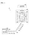
- FIG. 1 is a block diagram illustrating an overall configuration of a particle beam therapy device 10 according to a first embodiment.
- FIG. 2 is a block diagram illustrating a configuration of an accelerator control device 300 according to the first embodiment.
- FIG. 3 is a diagram illustrating an example of a power supply pattern S 4 according to the first embodiment.
- FIG. 4 is a timing chart illustrating an example of control of the blocker 155 when beam spikes occur.
- FIG. 5 is a timing chart illustrating an example of control of the blocker 155 according to the first embodiment.
- FIG. 6 is a diagram illustrating an example of a charge amount threshold value table 313 according to the first embodiment.
- FIG. 7 is a diagram illustrating another example of the charge amount threshold value table 313 according to the first embodiment.
- FIG. 8 is a diagram illustrating another example of a charge amount threshold value table 313 according to the first embodiment.
- FIG. 9 is a timing chart illustrating another example of the control of the blocker 155 according to the first embodiment.
- FIG. 10 is a block diagram illustrating a configuration of an accelerator control device 300 according to a second embodiment.
- FIG. 11 is a timing chart illustrating an example of control of a blocker 155 and a chopper 115 according to the second embodiment.
- FIG. 12 is a diagram illustrating an example of a pulse width threshold value table 315 according to the second embodiment.
- FIG. 13 is a diagram illustrating another example of the pulse width threshold value table 315 according to the second embodiment.
- FIG. 14 is a diagram illustrating another example of the pulse width threshold value table 315 according to the second embodiment.
- FIG. 15 is a block diagram illustrating a configuration of an accelerator control device 300 according to a third embodiment.
- FIG. 16 is a diagram illustrating an example of a current value threshold value table 316 according to the third embodiment.
- FIG. 17 is a diagram illustrating another example of the current value threshold value table 316 according to the third embodiment.
- FIG. 18 is a diagram illustrating another example of the current value threshold value table 316 according to the third embodiment.
- an accelerator control device has a high-frequency power controller and a timing controller.
- the high-frequency power controller supplies high frequency power for accelerating a charged particle beam to an accelerator.
- the timing controller controls an operation timing of a blocker that blocks the charged particle beam emitted from the accelerator based on a current value of the charged particle beam circulating in the accelerator.
- the accelerator control device of the embodiments can be applied not only to a particle beam therapy device but also to various devices using a charged particle beam.
- the present invention can also be applied to an etching device for processing a target by radiating a charged particle beam.
- FIG. 1 is a block diagram illustrating an overall configuration of a particle beam therapy device 10 according to a first embodiment.
- the particle beam therapy device 10 is a device that accelerates a charged particle beam to a desired energy and irradiates an affected part such as a tumor with the accelerated charged particle beam.
- the particle beam therapy device 10 includes an accelerator 100 , an irradiation device 200 , and an accelerator control device 300 .
- the accelerator 100 includes an injector 110 , a chopper 115 , a plurality of quadrupole electromagnets 120 a to 120 h , a plurality of deflection electromagnets 130 a to 130 d , a high-frequency acceleration cavity 140 , an emitter 150 , and a current value detector 190 .
- the injector 110 causes the charged particle beam to be incident on a circulating trajectory in the accelerator 100 .
- the chopper 115 is provided in order to adjust the amount of the charged particle beam that is incident on the accelerator 100 .
- a beam chopper that adjusts the incidence amount of the charged particle beam incident on the accelerator 100 by temporally switching and giving an electric or magnetic force for deflecting the charged particle beam may be used.
- the quadrupole electromagnets 120 a to 120 h are electromagnets that cause the charged particle beam to converge or diverge such that the charged particle beam stably circulates around the circulating trajectory.
- the deflection electromagnets 130 a to 130 d are electromagnets that cause the charged particle beam to circulate in the accelerator 100 by deflecting the charged particle beam.
- the current value detector 190 detects the current value of the charged particle beam circulating in the accelerator 100 .
- a plurality of electrodes are provided in the high-frequency acceleration cavity 140 .
- the charged particle beam is accelerated by applying a voltage to the plurality of electrodes provided in the high-frequency acceleration cavity 140 .
- the emitter 150 emits some of the charged particle beam circulating around the circulating trajectory in the accelerator 100 toward the irradiation device 200 by applying a high frequency electric field to an emission electrode provided in the accelerator 100 .
- a blocker 155 , a plurality of quadrupole electromagnets 160 a to 160 d , a plurality of correction electromagnets 170 a to 170 d , and a deflection electromagnet 180 are provided in a path from the accelerator 100 to the irradiation device 200 .
- the blocker 155 is a shutter that blocks the charged particle beam emitted from the accelerator, but is not limited thereto as long as the blocker 155 can control the amount of beam reaching the irradiation device 200 .
- the blocker 155 may be a deflection electromagnet that guides the charged particle beam emitted from the accelerator to a path different from the path to the irradiation device 200 , or an electrode that generates an electric field.
- the quadrupole electromagnets 160 a to 160 d are electromagnets that cause the charged particle beam to converge or diverge such that the charged particle beam stably passes through the path from the accelerator 100 to the irradiation device 200 and the charged particle beam has a target beam diameter at an irradiation position.
- the deflection electromagnet 180 is an electromagnet for deflecting the charged particle beam and guiding the charged particle beam from the accelerator 100 to the irradiation device 200 .
- the correction electromagnets 170 a to 170 d are electromagnets for correcting a trajectory of the charged particle beam from the accelerator 100 to the irradiation device 200 .
- the irradiation device 200 is a device that is installed in a treatment room and irradiates an affected part such as a tumor with the charged particle beam accelerated by the accelerator 100 .
- the irradiation device 200 includes a dose monitor 210 .
- the dose monitor 210 detects intensity of the charged particle beam with which the affected part is irradiated.
- the accelerator control device 300 is a device that controls the accelerator 100 that accelerates the charged particle beam. Hereinafter, a detailed configuration of the accelerator control device 300 will be described.
- FIG. 2 is a block diagram illustrating a configuration of the accelerator control device 300 according to the first embodiment.
- the accelerator control device 300 includes a timing controller 310 , a high-frequency power pattern storage unit 320 , a power supply pattern storage unit 330 , a high-frequency power controller 340 , a power supply controller 350 , a chopper controller 360 , an injector controller 370 , an emitter controller 380 , and a blocker controller 390 .
- the timing controller 310 , the high-frequency power controller 340 , the power supply controller 350 , the chopper controller 360 , the injector controller 370 , the emitter controller 380 , and the blocker controller 390 are realized by hardware.
- Examples of such hardware include a field-programmable gate array (FPGA), a large scale integration (LSI), and an application specific integrated circuit (ASIC).
- FPGA field-programmable gate array
- LSI large scale integration
- ASIC application specific integrated circuit
- the accelerator control device 300 may include a processor such as a central processing unit (CPU), and a program memory that stores a program to be executed by the processor.
- the timing controller 310 , the high-frequency power controller 340 , the power supply controller 350 , the chopper controller 360 , the injector controller 370 , the emitter controller 380 , and the blocker controller 390 may be realized by the processor executing the program stored in the program memory.
- the timing controller 310 controls a timing at which the charged particle beam is incident on the accelerator 100 and controls a timing at which the charged particle beam is emitted from the accelerator 100 .
- the timing controller 310 outputs a beam incidence signal S 11 to the injector controller 370 when the charged particle beam is incident on the circulating trajectory in the accelerator 100 .
- the injector controller 370 supplies incidence power S 12 to the injector 110 provided in the accelerator 100 according to the beam incidence signal S 11 input from the timing controller 310 .
- the injector 110 causes the charged particle beam to be incident on the circulating trajectory in the accelerator 100 .
- the timing controller 310 outputs a beam emission signal S 13 to the emitter controller 380 .
- the emitter controller 380 supplies output power S 14 to the emitter 150 provided in the accelerator 100 according to the beam emission signal S 13 input from the timing controller 310 .
- the emission power S 14 is supplied from the emitter controller 380 , the emitter 150 emits the charged particle beam from the circulating trajectory in the accelerator 100 toward the irradiation device 200 .
- the timing controller 310 controls an operation timing of the blocker 155 that blocks the charged particle beam and controls an operation timing of the chopper 115 for adjusting the amount of the charged particle beam that is incident on the accelerator 100 .
- the timing controller 310 outputs a chopper pulse signal S 9 to the chopper controller 360 when the amount of the charged particle beam incident from the injector 110 is adjusted. While the chopper pulse signal S 9 input from the timing controller 310 is ON, the chopper controller 360 supplies chopper power S 10 to the chopper 115 provided in the accelerator 100 . When the chopper power S 10 is supplied from the chopper controller 360 , the chopper 115 passes the charged particle beam incident from the injector 110 . On the other hand, when the chopper power S 10 is not supplied from the chopper controller 360 , the chopper 115 blocks the charged particle beam incident from the injector 110 .
- the chopper controller 360 supplies the chopper power S 10 to the chopper 115 while the chopper pulse signal S 9 is ON and does not supply the chopper power S 10 to the chopper 115 while the chopper pulse signal S 9 is OFF, but the present invention is not limited thereto.
- the chopper controller 360 may not supply the chopper power S 10 to the chopper 115 while the chopper pulse signal S 9 is ON but may supply the chopper power S 10 to the chopper 115 while the chopper pulse signal S 9 is OFF.
- the timing controller 310 outputs a blocker driving signal S 15 to the blocker controller 390 .
- the blocker controller 390 supplies blocker power S 16 to the blocker 155 .
- the blocker power S 16 is supplied from the blocker controller 390
- the blocker 155 blocks the charged particle beam emitted from the emitter 150 .
- the blocker power S 16 is not supplied from the blocker controller 390
- the blocker 155 passes the charged particle beam emitted from the emitter 150 .
- the blocker controller 390 supplies the blocker power S 16 to the blocker 155 while the blocker driving signal S 15 is ON, and the blocker controller 390 does not supply the blocker power S 16 to the blocker 155 while the blocker driving signal S 15 is OFF, but the present invention is not limited thereto.
- the blocker controller 390 may not supply the blocker driving signal S 15 to the blocker 155 while the blocker driving signal S 15 is ON, and the blocker controller 390 may supply the blocker driving signal S 15 to the blocker 155 while the blocker driving signal S 15 is OFF.
- a computer 400 is connected to the accelerator control device 300 over a network.
- the computer 400 transmits the input high-frequency power pattern S 3 and the input power supply pattern S 4 to the accelerator control device 300 .
- the accelerator control device 300 receives the high-frequency power pattern S 3 and the power supply pattern S 4 from the computer 400 , the accelerator control device 300 stores the received high-frequency power pattern S 3 in the high-frequency power pattern storage unit 320 and also stores the received power supply pattern S 4 in the power supply pattern storage unit 330 .
- the computer 400 can also set setting values necessary for an operation logic of the emitter controller 380 and setting values necessary for an operation logic of the timing controller 310 .
- the high-frequency power pattern S 3 is data indicating a power command pattern for controlling power supplied to a plurality of electrodes provided in the high-frequency acceleration cavity 140 .
- the high-frequency power pattern S 3 includes a set of voltage command values for instructing amplitudes of voltages applied to the plurality of electrodes provided in the high-frequency acceleration cavity 140 , and a set of frequency command values for instructing frequencies of the voltages applied to the plurality of electrodes, which are executed (output) in a specific order (read as a voltage command value S 5 ).
- the power supply pattern S 4 is data indicating a current command pattern for controlling currents to be supplied to the plurality of deflection electromagnets 130 a to 130 d provided in the accelerator 100 . That is, the power supply pattern S 4 is a set of current command values for instructing the currents to be supplied to the plurality of deflection electromagnets 130 a to 130 d provided in the accelerator 100 , which are executed (output) in a specific order (read as a current command value S 7 ).
- the timing controller 310 outputs a reset signal S 1 and a clock signal S 2 to the high-frequency power pattern storage unit 320 .
- the reset signal S 1 is a signal for resetting so that the current command value S 5 is generated from the first data of the high-frequency power pattern S 3 (read from the first data).
- the clock signal S 2 is a synchronization signal that is used when updating is performed so that the voltage command value S 5 is generated from the next data of the high-frequency power pattern S 3 (read from the next data).
- the timing controller 310 also outputs the reset signal S 1 and the clock signal S 2 to the power supply pattern storage unit 330 .
- the reset signal S 1 is also a signal for resetting so that the current command value S 7 is generated from the first data of the power supply pattern S 4 (read from the first data).
- the clock signal S 2 is also a synchronization signal that is used when updating is performed so that the current command value S 7 is generated from the next data of the power supply pattern S 4 (read from the next data).
- FIG. 3 is a diagram illustrating an example of the power supply pattern S 4 according to the first embodiment.
- a horizontal axis indicates time and a vertical axis indicates the current command value for controlling the current supplied from the power supply controller 350 to the deflection electromagnets 130 a to 130 d . That is, the power supply pattern S 4 illustrated in FIG. 3 is read as the current command value S 7 from the leftmost current command value (an initial current command value) in FIG. 3 . Further, each time the clock signal S 2 is input, the next (right adjacent) current command value is sequentially read as the current command value S 7 .
- the power supply pattern S 4 illustrated in FIG. 3 is a pattern in which the current command value increases to a current command value A 1 , and then decreases to a current command value A 2 , a current command value A 3 , . . . , a current command value An.
- the current command values are forcibly executed in order from the first current command value (a leftmost current command value in FIG. 3 ) of the power supply pattern S 4 .
- the power supply controller 350 counts the number of inputs of the clock signal S 2 and reads the current command value S 7 corresponding to a count value from the power supply pattern storage unit 330 .
- the power supply controller 350 supplies a current S 8 corresponding to the current command value S 7 read from the power supply pattern storage unit 330 to the deflection electromagnets 130 a to 130 d .
- the power supply controller 350 repeats this operation each time the clock signal S 2 is input from the timing controller 310 .
- the power supply pattern S 4 near a timing at which the reset signal S 1 is output indicates a current command value corresponding to energy of an incidence level of the charged particle beam.
- the timing controller 310 outputs the beam incidence signal S 11 to the injector controller 370 when the current command value is output to the power supply controller 350
- the injector controller 370 supplies the incidence power S 12 to the injector 110 .
- the incidence power S 12 is supplied to the injector 110
- the charged particle beam is output from an ion source (not illustrated), and the injector 110 accelerates the charged particle beam to incidence energy.
- the timing controller 310 outputs the chopper pulse signal S 9 to the chopper controller 360 at a timing slightly delayed from the beam incidence signal S 11 . While the chopper pulse signal S 9 input from the timing controller 310 is ON, the chopper controller 360 supplies the chopper power S 10 to the chopper 115 provided in the accelerator 100 . When the chopper power S 10 is supplied from the chopper controller 360 , the chopper 115 passes the charged particle beam incident from the injector 110 .
- the charged particle beam that has passed through the chopper 115 is incident on the circulating trajectory of the accelerator 100 . Thereafter, acceleration energy is given to the charged particle beam according to the current command value S 7 output from the power supply pattern storage unit 330 and the voltage command value S 5 output from the high-frequency power pattern storage unit 320 . Accordingly, the charged particle beam circulates in the accelerator 100 and accelerates.
- the same control is performed on the current given to the quadrupole electromagnets 120 a to 120 h provided in the accelerator 100 or a current value given to other electromagnets (not illustrated). Normally, resetting, incidence, acceleration, and deceleration are repeated according to the current command value S 7 output from the power supply pattern storage unit 330 and the voltage command value S 5 output from the high-frequency power pattern storage unit 320 .
- the current command value S 7 does not directly indicate a magnitude of the energy of the charged particle beam.
- the current command value S 7 is a value that is uniquely determined on the basis of the energy (speed) of the charged particle beam.
- the current supplied to the deflection electromagnets 130 a to 130 d is required to be increased. Therefore, the current command value S 7 illustrated in FIG. 2 can also be interpreted as the magnitude of the energy of the charged particle beam.
- the high-frequency power controller 340 similarly counts the number of inputs of the clock signal S 2 and reads the voltage command value S 5 corresponding to a count value from the high-frequency power pattern storage unit 320 .
- the high-frequency power controller 340 applies a voltage S 6 according to the voltage command value S 5 read from the high-frequency power pattern storage unit 320 to the plurality of electrodes provided in the high-frequency acceleration cavity 140 .
- the high-frequency power controller 340 repeats this operation each time the clock signal S 2 is input from the timing controller 310 .
- the current value detector 190 provided in the accelerator 100 detects the current value S 17 of the charged particle beam circulating in the accelerator 100 and transmits the detected current value S 17 to the accelerator control device 300 .
- the current value S 17 transmitted from the current value detector 190 is input to the timing controller 310 .
- the high-frequency power controller 340 includes a frequency detector 341 .
- the frequency detector 341 detects a frequency S 18 at which the charged particle beam circulates in the accelerator 100 .
- the frequency detector 341 detects the frequency S 18 at which the charged particle beam circulates in the accelerator 100 on the basis of the frequency of the voltage applied from the high-frequency power controller 340 to the high-frequency acceleration cavity 140 .
- the frequency detector 341 outputs the detected frequency S 18 to the timing controller 310 .
- the timing controller 310 includes a charge amount calculator 311 , a pre-emission controller 312 , and a charge amount threshold value table 313 (first table).
- the charge amount calculator 311 calculates the amount of charge of the charged particle beam by dividing the current value S 17 detected by the current value detector 190 by the frequency S 18 detected by the frequency detector 341 .
- a phenomenon called beam spikes in which intensity of the charged particle beam exceeds a target value may occur immediately after the charged particle beam accelerated to a certain energy by the accelerator 100 is emitted. Therefore, the pre-emission controller 312 performs pre-emission in order to prevent occurrence of the beam spikes.
- the “pre-emission” is an operation of emitting the charged particle beam from the circulating trajectory in the accelerator 100 toward the irradiation device 200 in a state in which the blocker 155 is closed.
- FIG. 4 is a timing chart illustrating an example of control of the blocker 155 when beam spikes occur.
- the timing controller 310 stops the clock signal S 2 at a timing when the current command value S 7 reaches A 180 . Accordingly, the current supplied to the deflection electromagnets 130 a to 130 d can be kept constant, such that the energy of the charged particle beam can be kept constant.
- the timing controller 310 After making the energy of the charged particle beam constant, the timing controller 310 outputs the blocker driving signal S 15 for closing the blocker 155 to the blocker controller 390 . While the blocker driving signal S 15 is ON, the blocker controller 390 supplies the blocker power S 16 to the blocker 155 . When the blocker power S 16 is supplied to the blocker 155 , the blocker 155 blocks a path of the charged particle beam from the emitter 150 to the irradiation device 200 .
- the timing controller 310 After the blocker 155 is closed, the timing controller 310 outputs the beam emission signal S 13 for emitting the charged particle beam from the circulating trajectory in the accelerator 100 to the emitter controller 380 until a predetermined time T elapses.
- the emitter controller 380 supplies the output power S 14 to the emitter 150 according to the beam emission signal S 13 .
- the emission power S 14 is supplied to the emitter 150 , the emitter 150 emits the charged particle beam from the circulating trajectory in the accelerator 100 toward the irradiation device 200 .
- the timing controller 310 stops outputting the beam emission signal S 13 . Accordingly, the emitter 150 stops emitting the charged particle beam.
- the timing controller 310 stops outputting the blocker driving signal S 15 . Accordingly, the blocker 155 shifts from a closed state to an open state, and a path of the charged particle beam from the emitter 150 to the irradiation device 200 is released. Thereafter, the timing controller 310 outputs the beam emission signal S 13 to the emitter controller 380 in order to perform main emission and causes the charged particle beam to be emitted from the emitter 150 to the irradiation device 200 .
- the beam spikes may occur even when pre-emission for blocking the charged particle beam is performed until the predetermined dine T elapses.
- the dose monitor 210 of the irradiation device 200 detects the occurrence of the beam spikes in which intensity of the charged particle beam exceeds the target value. Therefore, the pre-emission controller 312 needs to control a time to continue the pre-emission in order to prevent the occurrence of the beam spikes.
- the timing controller 310 holds the charge amount threshold value table 313 in which the energy of the charged particle beam is associated with the threshold value of the amount of charge (beam charge amount) of the charged particle beam.
- the charge amount threshold value table 313 is a table that is stored in a memory provided in the accelerator control device 300 .
- FIG. 6 is a diagram illustrating an example of the charge amount threshold value table 313 according to the first embodiment.
- the charge amount threshold value table 313 is a table in which the energy number is associated with the threshold value of the beam charge amount. Specifically, threshold values 100 [nC] to 1 [nC] are associated with energy numbers 1 to 200, respectively. It should be noted that energy number 1 is 430 [MeV], . . . , and energy number 200 is 50 [MeV].
- the charge amount threshold value table 313 is set such that the threshold value associated with the energy becomes smaller as the energy of the charged particle beam is lowered.
- the pre-emission controller 312 of the timing controller 310 acquires a threshold value corresponding to the energy of the charged particle beam circulating in the accelerator 100 from the charge amount threshold value table 313 .
- the pre-emission controller 312 controls the operation timing of the blocker 155 on the basis of a comparison between the amount of charge calculated by the charge amount calculator 311 and the threshold value acquired from the charge amount threshold value table 313 .
- the timing controller 310 controls the blocker 155 such that the charged particle beam is blocked.
- the timing controller 310 controls the blocker 155 such that the charged particle beam is passed.
- the pre-emission controller 312 acquires the threshold value TH 180 corresponding to the energy of A 180 from the charge amount threshold value table 313 .
- the pre-emission controller 312 closes the blocker 155 and performs pre-emission.
- the pre-emission controller 312 ends the pre-emission and opens the blocker 155 .
- the timing controller 310 performs main emission for emitting the charged particle beam to the irradiation device 200 .
- the pre-emission controller 312 continues the pre-emission until the amount of charge of the charged particle beam becomes smaller than the threshold value. Accordingly, it is possible to prevent the beam spikes from occurring even in a case in which the charged particle beam with low energy is emitted. In the first embodiment, the occurrence of the beam spikes is not detected by the dose monitor 210 of the irradiation device 200 , as illustrated in FIG. 5 .
- FIG. 7 is a diagram illustrating another example of the charge amount threshold value table 313 according to the first embodiment.
- a boundary energy number may be set in the charge amount threshold value table 313 .
- a beam charge amount threshold value 1 from energy number 1 to a boundary energy number and a beam charge amount threshold value 2 from the boundary energy number +1 to energy number 200 (a maximum value) may be set in the charge amount threshold value table 313 .
- a beam charge amount threshold value (20 [nC]) is associated with energy numbers 1 to 180 and a beam charge amount threshold value (1 [nC]) is associated with energy numbers 181 to 200.
- FIG. 8 is a diagram illustrating another example of the charge amount threshold value table 313 according to the first embodiment.
- boundary energy number 1 and boundary energy number 2 may be set in the charge amount threshold value table 313 .
- a beam charge amount threshold value 1 from energy number 1 to boundary energy number 1, a beam charge amount threshold value 2 from boundary energy number 1+1 to boundary energy number 2, and a beam charge amount threshold value 3 from boundary energy number 2+1 to energy number 200 (a maximum value) may be set.
- a beam charge amount threshold value (10 [nC]) is associated with energy numbers 1 to 150
- a beam charge amount threshold value (2 [nC]) is associated with energy numbers 151 to 180
- a beam charge amount threshold value (1 [nC]) is associated with energy numbers 181 to 200.
- the charge amount threshold value table 313 may include boundary energy for delimiting a range of energy, and a threshold value of the amount of charge of the charged particle beam may be associated with each range of energy delimited by the boundary energy. Accordingly, it is possible to reduce the amount of data of the charge amount threshold value table 313 .
- FIG. 9 is a timing chart illustrating another example of the control of the blocker 155 according to the first embodiment. Specifically, FIG. 9 is a timing chart illustrating the control of emitting the charged particle beam of a first energy stage (A 1 ) and the charged particle beam of a 180th energy stage (A 180 ).
- the charged particle beam incident on the accelerator 100 by the injector 110 is accelerated by the accelerator 100 .
- the timing controller 310 stops the clock signal S 2 . Accordingly, the energy of the charged particle beam is held at a constant value (A 1 ). In this case, since the amount of charge of the charged particle beam is smaller than the threshold value TH 1 , pre-emission is performed until the predetermined time T elapses. After the pre-emission is completed, main emission of the first energy stage (A 1 ) is performed.
- the timing controller 310 resumes the supply of the clock signal S 2 .
- the clock signal S 2 reaches a count value corresponding to the 180th energy stage (A 180 )
- the timing controller 310 stops the clock signal S 2 . Accordingly, the energy of the charged particle beam is held at a constant value (A 180 ).
- pre-emission is performed until a predetermined time Tp elapses (until the amount of charge of the charged particle beam becomes smaller than the threshold value TH 180 ). After the pre-emission is completed, the main emission of the 180th energy stage (A 180 ) is performed.
- the timing controller 310 controls the operation timing of the blocker 155 which blocks the charged particle beam emitted from the accelerator 100 on the basis of the current value of the charged particle beam circulating in the accelerator 100 . Specifically, the timing controller 310 calculates the amount of charge of the charged particle beam on the basis of the current value detected by the current value detector 190 , and controls an operation timing of the blocker 155 on the basis of the calculated amount of charge of the charged particle beam. Accordingly, it is possible to prevent beam spikes from occurring even in a case in which the charged particle beam with low energy is emitted.
- the timing controller 310 controls the operation timing of the blocker 155 that blocks the charged particle beam emitted from the accelerator 100 .
- the timing controller 310 controls the pulse width of the chopper pulse signal for driving the chopper 115 , in addition to controlling the operation timing of the blocker 155 .
- the second embodiment will be described in detail.
- FIG. 10 is a block diagram illustrating a configuration of the accelerator control device 300 according to a second embodiment.
- portions corresponding to those in FIG. 2 are denoted by the same reference numerals, and description thereof is omitted.
- the timing controller 310 includes a pulse width controller 314 and a pulse width threshold value table 315 (a second table) in addition to the charge amount calculator 311 , the pre-emission controller 312 , and the charge amount threshold value table 313 .
- the pulse width threshold value table 315 is a table that is stored in the memory provided in the accelerator control device 300 .
- the pulse width controller 314 performs pulse width control of the chopper pulse signal S 9 in order to prevent the beam spikes from occurring.
- the pulse width controller 314 adjusts the amount of the charged particle beam incident on the circulating trajectory in the accelerator 100 by performing the pulse width control.
- FIG. 11 is a timing chart illustrating an example of control of the blocker 155 and the chopper 115 according to the second embodiment.
- portions corresponding to the respective portions in FIG. 5 are denoted by the same reference numerals, and description thereof is omitted.
- FIG. 11 is a timing chart in a case in which the charged particle beam is emitted with low energy (A 180 ).
- the chopper controller 360 controls the chopper 115 on the basis of the energy of the charged particle beam when the charged particle beam is emitted from the accelerator 100 , thereby adjusting the amount of charged particle beam incident on the circulating trajectory in the accelerator 100 .
- FIG. 12 is a diagram illustrating an example of the pulse width threshold value table 315 according to the second embodiment.
- the pulse width threshold value table 315 is a table in which the energy of the charged particle beam and the pulse width of the chopper pulse signal for driving the chopper 115 are associated with each other. Specifically, chopper pulse widths of 40 [ ⁇ s] to 10 [ ⁇ s] are associated with energy numbers 1 to 200, respectively. It should be noted that energy number 1 is 430 [MeV], . . . , and energy number 200 is 50 [MeV].
- the pulse width threshold value table 315 is set such that the pulse width associated with the energy becomes smaller as the energy of the charged particle beam is lower.
- the pulse width controller 314 acquires the pulse width corresponding to the energy of the charged particle beam when the charged particle beam is emitted from the accelerator 100 from the pulse width threshold value table 315 .
- the chopper controller 360 controls the operation timing of the chopper 115 on the basis of the pulse width acquired by the pulse width controller 314 .
- the chopper controller 360 controls a time for supplying the chopper power S 10 to the chopper 115 on the basis of the pulse width acquired by the pulse width controller 314 . Specifically, when the chopper pulse width is 10 [ ⁇ s], the chopper controller 360 sets a supply time of the chopper power S 10 to 10 ⁇ s.
- the pulse width controller 314 controls the chopper pulse width for driving the chopper 115 on the basis of the energy of the charged particle beam when the charged particle beam is emitted from the accelerator 100 . Specifically, when the energy of the charged particle beam when the charged particle beam is emitted from the accelerator 100 is low, the pulse width controller 314 reduces the amount of charged particle beam incident on the circulating trajectory in the accelerator 100 by decreasing the chopper pulse width. Thus, it is possible to shorten the time required for pre-emission.
- FIG. 13 is a diagram illustrating another example of the pulse width threshold value table 315 according to the second embodiment.
- a boundary energy number may be set in the pulse width threshold value table 315 .
- a chopper pulse width 1 from energy number 1 to the boundary energy number and a chopper pulse width 2 from a boundary energy number +1 to energy number 200 (maximum value) may be set.
- the chopper pulse width (30 ⁇ s) is associated with energy numbers 1 to 180
- the chopper pulse width (10 ⁇ s) is associated with energy numbers 181 to 200.
- FIG. 14 is a diagram illustrating another example of the pulse width threshold value table 315 according to the second embodiment.
- boundary energy number 1 and boundary energy number 2 may be set in the pulse width threshold value table 315 .
- a chopper pulse width 1 from energy number 1 to boundary energy number 1, a chopper pulse width 2 from a boundary energy number 1+1 to boundary energy number 2, and a chopper pulse width 3 from boundary energy number 2+1 to energy number 200 (maximum value) may be set.
- a chopper pulse width (30 ⁇ s) is associated with energy numbers 1 to 100
- a chopper pulse width (20 ⁇ s) is associated with energy numbers 101 to 180
- a chopper pulse width (10 ⁇ s) is associated with energy numbers 181 to 200.
- the pulse width threshold value table 315 may include a boundary energy for delimiting the range of energy, and a chopper pulse width may be associated with each range of energy delimited by the boundary energy. Accordingly, it is possible to reduce the amount of data of the pulse width threshold value table 315 .
- the timing controller 310 acquires the pulse width corresponding to the energy of the charged particle beam when the charged particle beam is emitted from the accelerator 100 from the pulse width threshold value table 315 .
- the chopper controller 360 controls the operation timing of the chopper 115 on the basis of the pulse width acquired by the timing controller 310 . Thus, it is possible to prevent the beam spikes from occurring and shorten the time required for pre-emission.
- the timing controller 310 of the first embodiment and the second embodiment calculates the amount of charge of the charged particle beam on the basis of the current value of the charged particle beam circulating in the accelerator 100 and controls the operation timing of the blocker 155 on the basis of the calculated amount of charge of the charged particle beam.
- a timing controller 310 according to the third embodiment controls the operation timing of the blocker 155 on the basis of a current value (a beam current) of the charged particle beam circulating in the accelerator 100 without calculating the amount of charge of the charged particle beam.
- FIG. 15 is a block diagram illustrating a configuration of the accelerator control device 300 according to the third embodiment.
- portions corresponding to the respective portions in FIG. 10 are denoted by the same reference numerals, and description thereof is omitted.
- the timing controller 310 since the timing controller 310 does not calculate the amount of charge of the charged particle beam, the timing controller 310 does not include the charge amount calculator 311 . Further, the high-frequency power controller 340 does not include the frequency detector 341 .
- the timing controller 310 includes a current value threshold value table 316 (a third table), in addition to the pre-emission controller 312 , the pulse width controller 314 , and the pulse width threshold value table 315 .
- the current value threshold value table 316 is a table that is stored in the memory provided in the accelerator control device 300 .
- FIG. 16 is a diagram illustrating an example of the current value threshold value table 316 according to the third embodiment.
- the current value threshold value table 316 is a table in which the energy number and the threshold value of the beam current are associated with each other. Specifically, threshold values 50 [mA] to 0.5 [mA] are associated with energy numbers 1 to 200, respectively. It should be noted that energy number 1 is 430 [MeV], . . . , and energy number 200 is 50 [MeV].
- the current value threshold value table 316 is set such that the threshold value associated with the energy becomes smaller as the energy of the charged particle beam is lower.
- the timing controller 310 acquires a threshold value corresponding to the energy of the charged particle beam circulating in the accelerator 100 from the current value threshold value table 316 . Further, the pre-emission controller 312 of the timing controller 310 controls the operation timing of the blocker 155 on the basis of a comparison between the current value of the charged particle beam circulating in the accelerator 100 and the threshold value acquired from the current value threshold value table 316 .
- the timing controller 310 controls the blocker 155 such that the charged particle beam is blocked.
- the timing controller 310 controls the blocker 155 such that the charged particle beam is passed.
- the pre-emission controller 312 continues pre-emission until the current value of the charged particle beam becomes smaller than the threshold value. Accordingly, it is possible to prevent the beam spikes from occurring. In addition, since the charge amount calculator 311 and the frequency detector 341 are not required, it is possible to reduce costs of the accelerator control device 300 .
- FIG. 17 is a diagram illustrating another example of the current value threshold value table 316 according to the third embodiment.
- the boundary energy number may be set in the current value threshold value table 316 .
- a beam current threshold value 1 from energy number 1 to a boundary energy number and a beam current threshold value 2 from boundary energy number +1 to energy number 200 (a maximum value) may be set.
- a beam current threshold value (10 [mA]) is associated with energy numbers 1 to 180
- a beam current threshold value (0.5 [mA]) is associated with energy numbers 181 to 200.
- FIG. 18 is a diagram illustrating another example of the current value threshold value table 316 according to the third embodiment.
- boundary energy number 1 and boundary energy number 2 may be set in the current value threshold value table 316 .
- a beam current threshold value 1 from energy number 1 to boundary energy number 1, a beam current threshold value 2 from boundary energy number 1+1 to boundary energy number 2, and a beam current threshold value 3 from boundary energy number 2+1 to energy number 200 (a maximum value) may be set.
- the beam current threshold value (5 [mA]) is associated with energy numbers 1 to 150
- a beam current threshold value (1 [mA]) is associated with energy numbers 151 to 180
- a beam current threshold value (0.25 [mA]) is associated with energy numbers 181 to 200.
- the current value threshold value table 316 may include a boundary energy for delimiting a range of energy, and a threshold value of the current value of the charged particle beam may be associated with each range of energy delimited by the boundary energy. Accordingly, it is possible to reduce the amount of data of the current value threshold value table 316 .
- the accelerator control device 300 includes the high-frequency power controller 340 and the timing controller 310 .
- the high-frequency power controller 340 supplies high-frequency power for accelerating the charged particle beam to the accelerator 100 .
- the timing controller 310 controls the operation timing of the blocker 155 which blocks the charged particle beam emitted from the accelerator 100 on the basis of the current value of the charged particle beam circulating in the accelerator 100 . Accordingly, it is possible to prevent the beam spikes from occurring even in a case in which the charged particle beam with low energy is emitted.
Landscapes
- Health & Medical Sciences (AREA)
- Engineering & Computer Science (AREA)
- Biomedical Technology (AREA)
- Radiology & Medical Imaging (AREA)
- Pathology (AREA)
- Nuclear Medicine, Radiotherapy & Molecular Imaging (AREA)
- Life Sciences & Earth Sciences (AREA)
- Animal Behavior & Ethology (AREA)
- General Health & Medical Sciences (AREA)
- Public Health (AREA)
- Veterinary Medicine (AREA)
- Spectroscopy & Molecular Physics (AREA)
- Plasma & Fusion (AREA)
- Physics & Mathematics (AREA)
- Particle Accelerators (AREA)
- Radiation-Therapy Devices (AREA)
Applications Claiming Priority (2)
| Application Number | Priority Date | Filing Date | Title |
|---|---|---|---|
| JP2017091279A JP6936988B2 (ja) | 2017-05-01 | 2017-05-01 | 加速器制御装置、加速器制御方法、および粒子線治療装置 |
| JP2017-091279 | 2017-05-01 |
Publications (2)
| Publication Number | Publication Date |
|---|---|
| US20180317311A1 US20180317311A1 (en) | 2018-11-01 |
| US10420202B2 true US10420202B2 (en) | 2019-09-17 |
Family
ID=62063438
Family Applications (1)
| Application Number | Title | Priority Date | Filing Date |
|---|---|---|---|
| US15/963,641 Active US10420202B2 (en) | 2017-05-01 | 2018-04-26 | Accelerator control device, accelerator control method, and particle beam therapy device |
Country Status (6)
| Country | Link |
|---|---|
| US (1) | US10420202B2 (ja) |
| EP (1) | EP3402314B1 (ja) |
| JP (1) | JP6936988B2 (ja) |
| KR (1) | KR102057099B1 (ja) |
| CN (1) | CN108837333B (ja) |
| TW (1) | TWI678132B (ja) |
Cited By (1)
| Publication number | Priority date | Publication date | Assignee | Title |
|---|---|---|---|---|
| US11058899B1 (en) * | 2020-03-31 | 2021-07-13 | B Dot Medical Inc. | Superconducting electromagnet apparatus and charged particle irradiation apparatus |
Families Citing this family (6)
| Publication number | Priority date | Publication date | Assignee | Title |
|---|---|---|---|---|
| WO2020097874A1 (zh) * | 2018-11-15 | 2020-05-22 | 新瑞阳光粒子医疗装备 (无锡) 有限公司 | 加速器注入粒子数控制方法及装置、加速器和存储介质 |
| KR20200094577A (ko) * | 2019-01-30 | 2020-08-07 | 주식회사 모비스 | 인공신경망 시뮬레이터와 강화학습 제어기를 사용한 실시간 가속기 제어 시스템 |
| JP7290274B2 (ja) | 2019-07-04 | 2023-06-13 | 東芝エネルギーシステムズ株式会社 | 荷電粒子の出射制御装置、方法及びプログラム |
| CN110392479B (zh) * | 2019-07-31 | 2022-02-15 | 中广核达胜加速器技术有限公司 | 一种加速器的能量自动锻炼方法及系统 |
| JP7319144B2 (ja) * | 2019-08-30 | 2023-08-01 | 株式会社日立製作所 | 円形加速器および粒子線治療システム、円形加速器の作動方法 |
| JP7430044B2 (ja) * | 2019-09-17 | 2024-02-09 | 住友重機械工業株式会社 | 放射線治療装置 |
Citations (9)
| Publication number | Priority date | Publication date | Assignee | Title |
|---|---|---|---|---|
| JPS4873563A (ja) | 1972-01-08 | 1973-10-04 | ||
| JPH04264400A (ja) | 1991-02-19 | 1992-09-21 | Nippon Telegr & Teleph Corp <Ntt> | 荷電粒子ビーム加速装置 |
| JP2009148473A (ja) | 2007-12-21 | 2009-07-09 | Hitachi Ltd | 荷電粒子ビーム照射システム |
| JP2010251106A (ja) | 2009-04-15 | 2010-11-04 | Hitachi Ltd | 粒子線治療システム |
| JP2011034823A (ja) | 2009-08-03 | 2011-02-17 | Hitachi Ltd | 粒子線治療システム |
| JP4873563B2 (ja) | 2007-03-15 | 2012-02-08 | 独立行政法人放射線医学総合研究所 | 粒子加速器およびその運転方法、ならびに粒子線照射装置 |
| JP2013094313A (ja) | 2011-10-31 | 2013-05-20 | Hitachi Ltd | 粒子線照射システム及び荷電粒子ビームの補正方法 |
| EP2750484A1 (en) | 2012-12-27 | 2014-07-02 | Hitachi, Ltd. | Particle beam therapy system |
| US20160330827A1 (en) | 2014-03-25 | 2016-11-10 | Mitsubishi Electric Corporation | Circular accelerator, circular accelerator operation method, and particle-beam therapy device |
Family Cites Families (12)
| Publication number | Priority date | Publication date | Assignee | Title |
|---|---|---|---|---|
| JPH07275381A (ja) * | 1994-04-07 | 1995-10-24 | Toshiba Corp | ビーム治療装置 |
| US7053565B2 (en) * | 2002-07-03 | 2006-05-30 | Kronos Advanced Technologies, Inc. | Electrostatic fluid accelerator for and a method of controlling fluid flow |
| EP1736205B1 (en) * | 2003-05-13 | 2008-10-22 | Hitachi, Ltd. | Particle beam irradiation apparatus and treatment planning unit |
| JP3912364B2 (ja) * | 2003-11-07 | 2007-05-09 | 株式会社日立製作所 | 粒子線治療装置 |
| JP4158931B2 (ja) * | 2005-04-13 | 2008-10-01 | 三菱電機株式会社 | 粒子線治療装置 |
| JP4988516B2 (ja) * | 2007-11-06 | 2012-08-01 | 株式会社日立製作所 | 粒子線治療システム |
| JP4691583B2 (ja) * | 2008-07-02 | 2011-06-01 | 株式会社日立製作所 | 荷電粒子ビーム照射システムおよび荷電粒子ビーム出射方法 |
| JP5597162B2 (ja) * | 2011-04-28 | 2014-10-01 | 三菱電機株式会社 | 円形加速器、および円形加速器の運転方法 |
| JP5745069B2 (ja) * | 2011-08-31 | 2015-07-08 | 株式会社日立製作所 | 荷電粒子ビーム照射システムおよび荷電粒子ビーム照射システムの運転方法 |
| EP3043863B1 (en) * | 2013-09-11 | 2019-12-04 | The Board of Trustees of the Leland Stanford Junior University | Arrays of accelerating structures and rapid imaging for facilitating rapid radiation therapies |
| JP6242314B2 (ja) * | 2014-09-11 | 2017-12-06 | 住友重機械イオンテクノロジー株式会社 | イオン注入装置及びイオンビームの調整方法 |
| JP6427069B2 (ja) * | 2015-05-27 | 2018-11-21 | 株式会社日立製作所 | 粒子線治療システム |
-
2017
- 2017-05-01 JP JP2017091279A patent/JP6936988B2/ja active Active
-
2018
- 2018-04-25 EP EP18169320.1A patent/EP3402314B1/en active Active
- 2018-04-25 KR KR1020180047774A patent/KR102057099B1/ko active IP Right Grant
- 2018-04-26 US US15/963,641 patent/US10420202B2/en active Active
- 2018-04-26 TW TW107114236A patent/TWI678132B/zh active
- 2018-04-27 CN CN201810390828.0A patent/CN108837333B/zh active Active
Patent Citations (11)
| Publication number | Priority date | Publication date | Assignee | Title |
|---|---|---|---|---|
| JPS4873563A (ja) | 1972-01-08 | 1973-10-04 | ||
| JPH04264400A (ja) | 1991-02-19 | 1992-09-21 | Nippon Telegr & Teleph Corp <Ntt> | 荷電粒子ビーム加速装置 |
| JP4873563B2 (ja) | 2007-03-15 | 2012-02-08 | 独立行政法人放射線医学総合研究所 | 粒子加速器およびその運転方法、ならびに粒子線照射装置 |
| JP2009148473A (ja) | 2007-12-21 | 2009-07-09 | Hitachi Ltd | 荷電粒子ビーム照射システム |
| US7875868B2 (en) | 2007-12-21 | 2011-01-25 | Hitachi, Ltd. | Charged particle beam irradiation system |
| JP2010251106A (ja) | 2009-04-15 | 2010-11-04 | Hitachi Ltd | 粒子線治療システム |
| JP2011034823A (ja) | 2009-08-03 | 2011-02-17 | Hitachi Ltd | 粒子線治療システム |
| JP2013094313A (ja) | 2011-10-31 | 2013-05-20 | Hitachi Ltd | 粒子線照射システム及び荷電粒子ビームの補正方法 |
| SG189670A1 (en) | 2011-10-31 | 2013-05-31 | Hitachi Ltd | Particle beam irradiation system and charged particle beam correction method |
| EP2750484A1 (en) | 2012-12-27 | 2014-07-02 | Hitachi, Ltd. | Particle beam therapy system |
| US20160330827A1 (en) | 2014-03-25 | 2016-11-10 | Mitsubishi Electric Corporation | Circular accelerator, circular accelerator operation method, and particle-beam therapy device |
Non-Patent Citations (1)
| Title |
|---|
| Mizushima, K., et al. "Reliable Beam-Intensity Control Technique at the Himac Synchrotron", Proceedings of the 1st International Beam Instrumentation Conference, Tsukuba, Japan, 2012, pp. 143-145. |
Cited By (1)
| Publication number | Priority date | Publication date | Assignee | Title |
|---|---|---|---|---|
| US11058899B1 (en) * | 2020-03-31 | 2021-07-13 | B Dot Medical Inc. | Superconducting electromagnet apparatus and charged particle irradiation apparatus |
Also Published As
| Publication number | Publication date |
|---|---|
| JP6936988B2 (ja) | 2021-09-22 |
| JP2018189465A (ja) | 2018-11-29 |
| CN108837333B (zh) | 2021-02-09 |
| KR20180121830A (ko) | 2018-11-09 |
| TWI678132B (zh) | 2019-11-21 |
| TW201904361A (zh) | 2019-01-16 |
| EP3402314A1 (en) | 2018-11-14 |
| KR102057099B1 (ko) | 2019-12-18 |
| US20180317311A1 (en) | 2018-11-01 |
| EP3402314B1 (en) | 2021-11-24 |
| CN108837333A (zh) | 2018-11-20 |
Similar Documents
| Publication | Publication Date | Title |
|---|---|---|
| US10420202B2 (en) | Accelerator control device, accelerator control method, and particle beam therapy device | |
| US9142385B1 (en) | Charged particle beam treatment apparatus and method of adjusting path length of charged particle beam | |
| JP5978125B2 (ja) | 粒子線治療システム | |
| JP2013215442A (ja) | 粒子線治療システム | |
| SG189670A1 (en) | Particle beam irradiation system and charged particle beam correction method | |
| JP2007311125A (ja) | 荷電粒子ビーム加速器のビーム出射制御方法及び荷電粒子ビーム加速器を用いた粒子ビーム照射システム | |
| JP5159688B2 (ja) | 粒子線治療システム | |
| JP2017098000A (ja) | 粒子線加速システム、粒子線加速制御方法、及び粒子線治療装置 | |
| JP6257751B2 (ja) | 粒子線照射装置 | |
| JP2011034823A (ja) | 粒子線治療システム | |
| US9937361B2 (en) | Particle beam irradiation apparatus | |
| US20150265855A1 (en) | Charged-particle beam therapy apparatus and method for controlling charged-particle beam therapy apparatus | |
| JP3894215B2 (ja) | 荷電粒子ビームの出射方法及び粒子線照射システム | |
| JP6775148B2 (ja) | 加速器制御装置、加速器制御方法、および粒子線治療装置 | |
| WO2019038966A1 (ja) | 荷電粒子ビーム発生装置とそれを備えた粒子線治療装置、および荷電粒子ビーム発生装置の運転方法 | |
| WO2019242011A1 (zh) | 同步加速器控制方法、装置、设备及存储介质 | |
| US9210793B2 (en) | Charged particle beam radiation control device and charged particle beam radiation method | |
| JPH11233300A (ja) | 粒子加速器 | |
| JP2014170714A (ja) | シンクロトロンおよびそれを用いた粒子線治療システム | |
| CN114286492A (zh) | 具有用于电子束偏转的磁体单元的直线加速器系统 | |
| JP6553400B2 (ja) | 荷電粒子ビーム治療装置 | |
| JP5548571B2 (ja) | 粒子線照射システム | |
| CN116491226A (zh) | 用于在束系统中启动束输送的系统、装置和方法 | |
| JPH0443599A (ja) | 蓄積ビーム電流安定化制御方法 | |
| JP2018149181A (ja) | 荷電粒子線治療装置 |
Legal Events
| Date | Code | Title | Description |
|---|---|---|---|
| FEPP | Fee payment procedure |
Free format text: ENTITY STATUS SET TO UNDISCOUNTED (ORIGINAL EVENT CODE: BIG.); ENTITY STATUS OF PATENT OWNER: LARGE ENTITY |
|
| AS | Assignment |
Owner name: NATIONAL INSTITUTES FOR QUANTUM AND RADIOLOGICAL S Free format text: ASSIGNMENT OF ASSIGNORS INTEREST;ASSIGNORS:MATSUMOTO, MUNEMICHI;FURUKAWA, TAKUJI;MIZUSHIMA, KOTA;AND OTHERS;SIGNING DATES FROM 20180423 TO 20180515;REEL/FRAME:046273/0405 Owner name: TOSHIBA ENERGY SYSTEMS & SOLUTIONS CORPORATION, JA Free format text: ASSIGNMENT OF ASSIGNORS INTEREST;ASSIGNORS:MATSUMOTO, MUNEMICHI;FURUKAWA, TAKUJI;MIZUSHIMA, KOTA;AND OTHERS;SIGNING DATES FROM 20180423 TO 20180515;REEL/FRAME:046273/0405 |
|
| STPP | Information on status: patent application and granting procedure in general |
Free format text: DOCKETED NEW CASE - READY FOR EXAMINATION |
|
| STPP | Information on status: patent application and granting procedure in general |
Free format text: NOTICE OF ALLOWANCE MAILED -- APPLICATION RECEIVED IN OFFICE OF PUBLICATIONS |
|
| STPP | Information on status: patent application and granting procedure in general |
Free format text: AWAITING TC RESP., ISSUE FEE NOT PAID |
|
| STPP | Information on status: patent application and granting procedure in general |
Free format text: PUBLICATIONS -- ISSUE FEE PAYMENT VERIFIED |
|
| STCF | Information on status: patent grant |
Free format text: PATENTED CASE |
|
| AS | Assignment |
Owner name: TOSHIBA ENERGY SYSTEMS & SOLUTIONS CORPORATION, JAPAN Free format text: ASSIGNMENT OF ASSIGNORS INTEREST;ASSIGNOR:NATIONAL INSTITUTES FOR QUANTUM AND RADIOLOGICAL SCIENCE AND TECHNOLOGY;REEL/FRAME:057472/0691 Effective date: 20210906 |
|
| MAFP | Maintenance fee payment |
Free format text: PAYMENT OF MAINTENANCE FEE, 4TH YEAR, LARGE ENTITY (ORIGINAL EVENT CODE: M1551); ENTITY STATUS OF PATENT OWNER: LARGE ENTITY Year of fee payment: 4 |