US10372079B2 - Photosensitive member unit and development unit - Google Patents
Photosensitive member unit and development unit Download PDFInfo
- Publication number
- US10372079B2 US10372079B2 US15/953,732 US201815953732A US10372079B2 US 10372079 B2 US10372079 B2 US 10372079B2 US 201815953732 A US201815953732 A US 201815953732A US 10372079 B2 US10372079 B2 US 10372079B2
- Authority
- US
- United States
- Prior art keywords
- photosensitive member
- development
- unit
- development unit
- roller
- Prior art date
- Legal status (The legal status is an assumption and is not a legal conclusion. Google has not performed a legal analysis and makes no representation as to the accuracy of the status listed.)
- Active
Links
- 238000011161 development Methods 0.000 title claims abstract description 305
- 238000012546 transfer Methods 0.000 claims abstract description 37
- 238000013019 agitation Methods 0.000 claims description 26
- 230000004308 accommodation Effects 0.000 claims description 17
- 230000002093 peripheral effect Effects 0.000 claims description 15
- 238000011144 upstream manufacturing Methods 0.000 claims description 4
- 238000000034 method Methods 0.000 description 44
- 230000008569 process Effects 0.000 description 44
- 230000008878 coupling Effects 0.000 description 21
- 238000010168 coupling process Methods 0.000 description 21
- 238000005859 coupling reaction Methods 0.000 description 21
- 230000005540 biological transmission Effects 0.000 description 10
- 230000006835 compression Effects 0.000 description 10
- 238000007906 compression Methods 0.000 description 10
- 230000007246 mechanism Effects 0.000 description 5
- 238000003780 insertion Methods 0.000 description 4
- 230000037431 insertion Effects 0.000 description 4
- 230000009471 action Effects 0.000 description 2
- 238000013461 design Methods 0.000 description 2
- 230000000694 effects Effects 0.000 description 2
- 238000012423 maintenance Methods 0.000 description 2
- 239000000463 material Substances 0.000 description 2
- 230000001105 regulatory effect Effects 0.000 description 2
- 230000009286 beneficial effect Effects 0.000 description 1
- 230000008901 benefit Effects 0.000 description 1
- 230000015572 biosynthetic process Effects 0.000 description 1
- 230000007547 defect Effects 0.000 description 1
- 239000000428 dust Substances 0.000 description 1
- 230000006872 improvement Effects 0.000 description 1
- 230000009467 reduction Effects 0.000 description 1
- 230000000087 stabilizing effect Effects 0.000 description 1
- 239000000126 substance Substances 0.000 description 1
- 239000002699 waste material Substances 0.000 description 1
Images


Classifications
-
- G—PHYSICS
- G03—PHOTOGRAPHY; CINEMATOGRAPHY; ANALOGOUS TECHNIQUES USING WAVES OTHER THAN OPTICAL WAVES; ELECTROGRAPHY; HOLOGRAPHY
- G03G—ELECTROGRAPHY; ELECTROPHOTOGRAPHY; MAGNETOGRAPHY
- G03G21/00—Arrangements not provided for by groups G03G13/00 - G03G19/00, e.g. cleaning, elimination of residual charge
- G03G21/16—Mechanical means for facilitating the maintenance of the apparatus, e.g. modular arrangements
- G03G21/18—Mechanical means for facilitating the maintenance of the apparatus, e.g. modular arrangements using a processing cartridge, whereby the process cartridge comprises at least two image processing means in a single unit
- G03G21/1803—Arrangements or disposition of the complete process cartridge or parts thereof
- G03G21/1814—Details of parts of process cartridge, e.g. for charging, transfer, cleaning, developing
-
- G—PHYSICS
- G03—PHOTOGRAPHY; CINEMATOGRAPHY; ANALOGOUS TECHNIQUES USING WAVES OTHER THAN OPTICAL WAVES; ELECTROGRAPHY; HOLOGRAPHY
- G03G—ELECTROGRAPHY; ELECTROPHOTOGRAPHY; MAGNETOGRAPHY
- G03G15/00—Apparatus for electrographic processes using a charge pattern
- G03G15/06—Apparatus for electrographic processes using a charge pattern for developing
- G03G15/08—Apparatus for electrographic processes using a charge pattern for developing using a solid developer, e.g. powder developer
- G03G15/0806—Apparatus for electrographic processes using a charge pattern for developing using a solid developer, e.g. powder developer on a donor element, e.g. belt, roller
-
- G—PHYSICS
- G03—PHOTOGRAPHY; CINEMATOGRAPHY; ANALOGOUS TECHNIQUES USING WAVES OTHER THAN OPTICAL WAVES; ELECTROGRAPHY; HOLOGRAPHY
- G03G—ELECTROGRAPHY; ELECTROPHOTOGRAPHY; MAGNETOGRAPHY
- G03G15/00—Apparatus for electrographic processes using a charge pattern
- G03G15/06—Apparatus for electrographic processes using a charge pattern for developing
- G03G15/08—Apparatus for electrographic processes using a charge pattern for developing using a solid developer, e.g. powder developer
- G03G15/0896—Arrangements or disposition of the complete developer unit or parts thereof not provided for by groups G03G15/08 - G03G15/0894
-
- G—PHYSICS
- G03—PHOTOGRAPHY; CINEMATOGRAPHY; ANALOGOUS TECHNIQUES USING WAVES OTHER THAN OPTICAL WAVES; ELECTROGRAPHY; HOLOGRAPHY
- G03G—ELECTROGRAPHY; ELECTROPHOTOGRAPHY; MAGNETOGRAPHY
- G03G21/00—Arrangements not provided for by groups G03G13/00 - G03G19/00, e.g. cleaning, elimination of residual charge
- G03G21/16—Mechanical means for facilitating the maintenance of the apparatus, e.g. modular arrangements
- G03G21/1642—Mechanical means for facilitating the maintenance of the apparatus, e.g. modular arrangements for connecting the different parts of the apparatus
- G03G21/1652—Electrical connection means
-
- G—PHYSICS
- G03—PHOTOGRAPHY; CINEMATOGRAPHY; ANALOGOUS TECHNIQUES USING WAVES OTHER THAN OPTICAL WAVES; ELECTROGRAPHY; HOLOGRAPHY
- G03G—ELECTROGRAPHY; ELECTROPHOTOGRAPHY; MAGNETOGRAPHY
- G03G21/00—Arrangements not provided for by groups G03G13/00 - G03G19/00, e.g. cleaning, elimination of residual charge
- G03G21/16—Mechanical means for facilitating the maintenance of the apparatus, e.g. modular arrangements
- G03G21/18—Mechanical means for facilitating the maintenance of the apparatus, e.g. modular arrangements using a processing cartridge, whereby the process cartridge comprises at least two image processing means in a single unit
- G03G21/1803—Arrangements or disposition of the complete process cartridge or parts thereof
- G03G21/1817—Arrangements or disposition of the complete process cartridge or parts thereof having a submodular arrangement
- G03G21/1821—Arrangements or disposition of the complete process cartridge or parts thereof having a submodular arrangement means for connecting the different parts of the process cartridge, e.g. attachment, positioning of parts with each other, pressure/distance regulation
-
- G—PHYSICS
- G03—PHOTOGRAPHY; CINEMATOGRAPHY; ANALOGOUS TECHNIQUES USING WAVES OTHER THAN OPTICAL WAVES; ELECTROGRAPHY; HOLOGRAPHY
- G03G—ELECTROGRAPHY; ELECTROPHOTOGRAPHY; MAGNETOGRAPHY
- G03G21/00—Arrangements not provided for by groups G03G13/00 - G03G19/00, e.g. cleaning, elimination of residual charge
- G03G21/16—Mechanical means for facilitating the maintenance of the apparatus, e.g. modular arrangements
- G03G21/18—Mechanical means for facilitating the maintenance of the apparatus, e.g. modular arrangements using a processing cartridge, whereby the process cartridge comprises at least two image processing means in a single unit
- G03G21/1803—Arrangements or disposition of the complete process cartridge or parts thereof
- G03G21/1817—Arrangements or disposition of the complete process cartridge or parts thereof having a submodular arrangement
- G03G21/1825—Pivotable subunit connection
-
- G—PHYSICS
- G03—PHOTOGRAPHY; CINEMATOGRAPHY; ANALOGOUS TECHNIQUES USING WAVES OTHER THAN OPTICAL WAVES; ELECTROGRAPHY; HOLOGRAPHY
- G03G—ELECTROGRAPHY; ELECTROPHOTOGRAPHY; MAGNETOGRAPHY
- G03G21/00—Arrangements not provided for by groups G03G13/00 - G03G19/00, e.g. cleaning, elimination of residual charge
- G03G21/16—Mechanical means for facilitating the maintenance of the apparatus, e.g. modular arrangements
- G03G21/18—Mechanical means for facilitating the maintenance of the apparatus, e.g. modular arrangements using a processing cartridge, whereby the process cartridge comprises at least two image processing means in a single unit
- G03G21/1839—Means for handling the process cartridge in the apparatus body
- G03G21/1857—Means for handling the process cartridge in the apparatus body for transmitting mechanical drive power to the process cartridge, drive mechanisms, gears, couplings, braking mechanisms
- G03G21/1864—Means for handling the process cartridge in the apparatus body for transmitting mechanical drive power to the process cartridge, drive mechanisms, gears, couplings, braking mechanisms associated with a positioning function
-
- G—PHYSICS
- G03—PHOTOGRAPHY; CINEMATOGRAPHY; ANALOGOUS TECHNIQUES USING WAVES OTHER THAN OPTICAL WAVES; ELECTROGRAPHY; HOLOGRAPHY
- G03G—ELECTROGRAPHY; ELECTROPHOTOGRAPHY; MAGNETOGRAPHY
- G03G2221/00—Processes not provided for by group G03G2215/00, e.g. cleaning or residual charge elimination
- G03G2221/16—Mechanical means for facilitating the maintenance of the apparatus, e.g. modular arrangements and complete machine concepts
- G03G2221/1651—Mechanical means for facilitating the maintenance of the apparatus, e.g. modular arrangements and complete machine concepts for connecting the different parts
- G03G2221/166—Electrical connectors
-
- G—PHYSICS
- G03—PHOTOGRAPHY; CINEMATOGRAPHY; ANALOGOUS TECHNIQUES USING WAVES OTHER THAN OPTICAL WAVES; ELECTROGRAPHY; HOLOGRAPHY
- G03G—ELECTROGRAPHY; ELECTROPHOTOGRAPHY; MAGNETOGRAPHY
- G03G2221/00—Processes not provided for by group G03G2215/00, e.g. cleaning or residual charge elimination
- G03G2221/16—Mechanical means for facilitating the maintenance of the apparatus, e.g. modular arrangements and complete machine concepts
- G03G2221/18—Cartridge systems
- G03G2221/183—Process cartridge
- G03G2221/1853—Process cartridge having a submodular arrangement
Definitions
- the present invention relates to a cartridge, such as a photosensitive member unit or a development unit, which is attachable to and detachable from an image forming apparatus of an electrophotographic system.
- a toner image is formed on the surface of a photosensitive drum and the toner image is transferred onto a sheet, which is a recording material, thereby forming an image on the recording material.
- Japanese Patent Application Laid-Open No. 2016-224221 discusses a process cartridge having a structure in which a development unit that accommodates toner is attachable to and detachable from a photosensitive member unit including a photosensitive drum.
- the present disclosure is directed to improving at least one of a photosensitive member unit and a development unit which constitute a process cartridge.
- a photosensitive member unit includes a photosensitive member, a transfer roller, a first gear and a second gear each provided at one end of the photosensitive member in an axial direction of the photosensitive member, and a third gear provided at one end of the transfer roller in the axial direction of the photosensitive member and configured to engage with the second gear.
- the first gear, the second gear, and the third gear are helical gears.
- a direction in which helical teeth of the first gear are inclined is opposite to a direction in which helical teeth of the second gear are inclined, and the direction in which the helical teeth of the first gear are inclined matches a direction in which helical teeth of the third gear are inclined.
- FIG. 1 is a sectional view of an image forming apparatus including a process cartridge.
- FIGS. 2A and 2B are sectional views each illustrating a development unit.
- FIG. 3 is a perspective view of the development unit.
- FIG. 4 is an exploded perspective view of the development unit.
- FIG. 5 is a sectional view of the process cartridge.
- FIG. 6 is a top view of the development unit.
- FIG. 7 is a perspective view illustrating the development unit mounted on a photosensitive member unit and a lift member.
- FIG. 8 is a perspective view of the process cartridge.
- FIG. 9 is a partial perspective view of the photosensitive member unit.
- FIG. 10 is a perspective view illustrating the development unit and the photosensitive member unit.
- FIG. 11 is a perspective view of the process cartridge.
- FIG. 12 is a top view illustrating an arrangement relationship among the photosensitive member unit, the development unit, a development roller, and end seals in a right-and-left direction.
- FIG. 13 is a perspective view of the development unit as viewed from below.
- FIG. 14 is a partial perspective view illustrating the development unit and the lift member.
- FIG. 15 is a perspective view illustrating the development unit and the photosensitive member unit.
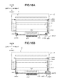
- FIGS. 16A and 16B are views each illustrating a positional relationship between the lift member and a pressing member.
- FIGS. 17A and 17B are views each illustrating a state where the development unit is removed.
- FIG. 18 is a view illustrating the photosensitive member unit on which the development unit is mounted as viewed from the right side.
- FIG. 19 is a view illustrating the development unit as viewed from the right side.
- FIG. 20 is a view illustrating a part of the development unit placed on a horizontal plane as viewed from the right side.
- FIG. 21 is a view illustrating the photosensitive member unit on which the development unit is mounted as viewed from the right side.
- FIG. 22 is a view illustrating the photosensitive member unit on which the development unit is mounted as viewed from the right side.
- the front side of the image forming apparatus 1 is referred to as “front”, the back surface side thereof is referred to as “back”, the upper surface (top surface) side thereof is referred to as “upper”, and the lower surface (bottom surface) side thereof is referred to as “lower”.
- the left side of the image forming apparatus 1 is referred to as “left” and the right side of the image forming apparatus 1 is referred to as “right”.
- the directions are defined in the same manner as of the image forming apparatus 1 , assuming that the process cartridge 5 is in the same posture as the state in which the process cartridge 5 is mounted on the image forming apparatus 1 .
- the directions in the drawings are defined by arrows illustrated in the drawings.
- a front-and-back direction, an up-and-down direction, and a right-and-left direction indicated by the arrows are directions orthogonal to each other. These directions are set in the same manner in all the drawings.
- the up-and-down direction is parallel to the vertical direction
- the right-and-left direction and the front-and-back direction are parallel to the horizontal direction.
- the right-and-left direction is parallel to each of a rotational axis direction of a photosensitive drum 61 and a rotational axis direction of a development roller 71 .
- a structure in which a development unit 7 is integrally mounted on a photosensitive member unit 6 is referred to as the process cartridge 5 .
- An insertion direction (mounting direction) S 1 in which the process cartridge 5 is mounted on an apparatus main body 2 and a detaching direction S 2 in which the process cartridge 5 is detached from the apparatus main body 2 are parallel to the front-and-back direction and orthogonal to each of the right-and-left direction and the up-and-down direction.
- FIG. 1 is a sectional view of the image forming apparatus 1 on which the process cartridge 5 is mounted, and the cross-section of the image forming apparatus 1 is parallel to each of the up-and-down direction and the front-and-back direction.
- the image forming apparatus 1 mainly includes a sheet feed unit 3 for supplying sheets S into the apparatus main body 2 , an exposure device 4 , the process cartridge 5 for transferring a toner image onto each sheet S, and a fixing device 8 for heat-fixing the transferred toner image onto the sheet S.
- the sheet feed unit 3 is provided at a lower portion within the apparatus main body 2 , and mainly includes a sheet feed tray 31 and a sheet feeding mechanism 32 .
- the sheets S accommodated in the sheet feed tray 31 are supplied to the process cartridge 5 (the photosensitive drum 61 and a transfer roller 63 ) by the sheet feeding mechanism 32 .
- the exposure device 4 is disposed at an upper portion within the apparatus main body 2 and includes a laser light emitting unit (not illustrated), a polygon mirror, a lens, a reflecting mirror, and the like (whose reference numerals are omitted).
- laser light based on image data output from the laser light emitting unit is scanned at a high speed on the surface of the photosensitive drum 61 , thereby exposing the surface of the photosensitive drum 61 to light.
- the process cartridge 5 is disposed below the exposure device 4 .
- the process cartridge 5 is inserted into an accommodation portion 23 of the apparatus main body 2 in the insertion direction S 1 from an opening formed when a door (openable and closable member) 21 , which is provided on the apparatus main body 2 , is opened (as indicated by an alternate long and two short dashes line in FIG. 1 ), and the process cartridge 5 is mounted on the apparatus main body 2 .
- the process cartridge 5 is detached from the apparatus main body 2 , the process cartridge 5 is moved and taken out in the detaching direction S 2 .
- the process cartridge 5 mainly includes the photosensitive member unit 6 and the development unit 7 .
- the photosensitive member unit 6 mainly includes the photosensitive drum 61 , a charging roller 62 , and the transfer roller 63 .
- the development unit 7 is attachable to and detachable from the photosensitive member unit 6 .
- the development unit 7 mainly includes a development roller 71 , a supply roller 72 , a layer thickness regulation blade 73 , a toner accommodation portion (developer accommodation portion) 74 that accommodates toner (developer), and a first agitator 75 A and a second agitator 75 B, which are provided within the toner accommodation portion 74 .
- the photosensitive drum 61 is rotationally driven during execution of the image forming process. First, the surface of the photosensitive drum 61 is uniformly charged by the charging roller 62 and is then exposed to laser light corresponding to image data output from the exposure device 4 , thereby forming an electrostatic latent image corresponding to the image data on the surface of the photosensitive drum 61 .
- the toner accommodated in the toner accommodation portion 74 is agitated by the second agitator 75 B and the first agitator 75 A and is then supplied to the development roller 71 through the supply roller 72 .
- the toner supplied to the development roller 71 enters the space between the development roller 71 and the layer thickness regulation blade 73 and is borne on the surface of the development roller 71 as a thin layer with a constant thickness.
- the toner borne on the surface of the development roller 71 is supplied to the electrostatic latent image formed on the surface of the photosensitive drum 61 .
- the toner is attached to the electrostatic latent image to form a visible image, so that a toner image is formed on the surface of the photosensitive drum 61 .
- the sheet S is conveyed to between the photosensitive drum 61 and the transfer roller 63 , and the toner image formed on the surface of the photosensitive drum 61 is transferred onto the sheet S.
- the fixing device 8 is disposed at the back side of the process cartridge 5 and mainly includes a heat roller 81 and a pressure roller 82 . While the sheet S having the toner image transferred thereto passes through the fixing device 8 , the sheet S is heated and pressed between the heat roller 81 and the pressure roller 82 , and the toner image is fixed onto the sheet S. The sheet S that has passed through the fixing device 8 is discharged onto a sheet discharge tray 22 .
- the process cartridge 5 includes the photosensitive member unit 6 and the development unit 7 that is attachable to and detachable from the photosensitive member unit 6 .
- FIGS. 2A and 2B are sectional views each illustrating the development unit 7 placed on a horizontal plane.
- FIG. 2A is a sectional view taken along a line A-A of FIG. 3
- FIG. 2B is a sectional view taken along a line B-B of FIG. 3 .
- the cross-section taken along the line A-A and the cross-section taken along the line B-B are parallel to each other in the up-and-down direction and the front-and-back direction.
- FIG. 3 is a perspective view of the development unit 7 placed on a horizontal plane.
- FIG. 4 is an exploded perspective view of the development unit 7 .
- FIG. 5 is a sectional view of the development unit 7 that is mounted on the photosensitive member unit 6 placed on a horizontal plane, and the cross-section of the development unit 7 is parallel to each other in the up-and-down direction and the front-and-back direction.
- FIG. 6 is a top view of the development unit 7 and illustrates a state where the top surface of a housing 700 is removed for convenience of explanation.
- FIG. 13 is a perspective view of the development unit 7 as viewed from below.
- the development unit 7 includes a gripping portion 701 for the user to grip and is provided at the front side of the housing 700 serving as a development frame member.
- the development roller 71 is rotatably supported at the back side of the development unit 7 .
- the rotational axis direction of the development roller 71 is hereinafter referred to as an axial direction.
- the gripping portion 701 is disposed at a position overlapping the housing 700 as viewed along a cross-section orthogonal to the axial direction.
- the gripping portion 701 is disposed substantially at a central portion of the housing 700 in the axial direction. More specifically, as illustrated in FIG. 3 , the gripping portion 701 is disposed between a first housing portion 700 A and a second housing portion 700 B, which respectively include spaces and 700 B 1 , to accommodate toner therein, in the axial direction.
- the space is an inside space of the first housing portion 700 A. The illustration of the space is omitted because the arrangement relationship between the first housing portion 700 A and the space is similar to the arrangement relationship between the second housing portion 700 B and the space 700 B 1 illustrated in FIG. 2B .
- a peripheral space of the gripping portion 701 can be used as a toner accommodation space. If there is a limitation on the width of the development unit in the front-and-back direction, the employment of the configuration according to the present exemplary embodiment enables accommodation of a larger amount of toner in this way.
- the advantageous effect described above can be obtained as long as at least a part of the gripping portion 701 overlaps the first housing portion 700 A and the second housing portion 700 B as viewed along the cross-section orthogonal to the axial direction.
- the length of the gripping portion 701 in the axial direction is desirably set as small as possible without impairing the usability.
- both ends of each of the development roller 71 , the supply roller 72 , the first agitator (first agitation member) 75 A, and the second agitator (second agitation member) 75 B are rotatably supported on a left side wall 704 and a right side wall 705 of the housing 700 .
- a development coupling 710 , a development roller gear 711 , a supply roller gear 712 , a first agitator gear 713 , a second agitator gear 714 , and idle gears 715 A, 715 B, and 715 C are provided.
- the development roller gear 711 is fixed to an end of the development roller 71
- the supply roller gear 712 is fixed to an end of the supply roller 72
- the first agitator gear 713 is fixed to an end of an agitation bar 78 A (see FIG. 5 ) of the first agitator 75 A
- the second agitator gear 714 is fixed to an end of an agitation bar 78 B (see FIG. 5 ) of the second agitator 75 B.
- a development drive transmission member (not illustrated) provided on the apparatus main body 2 moves to a position to engage with the development coupling 710 interlocking with an operation of closing a door 21 provided on the apparatus main body 2 .
- the development drive transmission member moves to a position to release the engagement with the development coupling 710 interlocking with an operation of opening the door 21 .
- a driving force is transmitted (input) to the development coupling 710 , which is a driving force receiving member, from the development drive transmission member, and the development roller 71 becomes rotatable through the development roller gear 711 from a gear that is provided on the peripheral surface of the development coupling 710 , and the supply roller 72 becomes rotatable through the supply roller gear 712 .
- the development drive transmission member is configured to permit positional deviation of the development coupling 710 within a predetermined range and is capable of transmitting the driving force to the development coupling 710 .
- the movement of each of the development coupling 710 , the development roller gear 711 , and the supply roller gear 712 in the axial direction is regulated by a side holder 719 attached to the housing 700 .
- the development unit 7 includes two agitators, i.e., the first agitator 75 A and the second agitator 75 B, to agitate the toner accommodated in the toner accommodation portion 74 so that the toner can be used up.
- the first agitator 75 A includes the agitation bar 78 A and an agitation sheet 79 A.
- the first agitator 75 A is configured to be rotatable by receiving, with the first agitator gear 713 , the driving force from the development coupling 710 through the idle gear 715 A.
- the second agitator 75 B includes the agitation bar 78 B and an agitation sheet 79 B.
- the second agitator 75 B is configured to be rotatable by receiving, with the second agitator gear 714 , the driving force from the first agitator gear 713 through the idle gears 715 B and 715 C.
- the second agitator 75 B supplies the first agitator 75 A with the toner accommodated in the toner accommodation portion 74 .
- the toner located near the first agitator 75 A within the toner accommodation portion 74 is agitated by the first agitator 75 A and supplied to the supply roller 72 and further supplied to the development roller 71 by the supply roller 72 .
- FIG. 8 is a perspective view of the process cartridge 5 placed on a horizontal plane.
- FIG. 9 is a partial perspective view of the photosensitive member unit 6 placed on a horizontal plane.
- FIG. 10 is a perspective view illustrating the development unit 7 and the photosensitive member unit 6 placed on a horizontal plane.
- FIG. 11 is a perspective view of the process cartridge 5 placed on a horizontal plane.
- FIG. 12 is a top view illustrating the arrangement relationship between the photosensitive member unit 6 , the development unit 7 , the development roller 71 , and end seals 717 in the right-and-left direction.
- FIG. 12 illustrates a state where the development roller 71 and the end seals 717 are taken out of the development unit 7 without changing the positions of the development roller 71 and the end seals 717 in the right-and-left direction.
- the photosensitive member unit 6 mainly includes a frame 610 including a pair of side walls, i.e. a left side wall 611 and a right side wall 612 , and a photosensitive drum 61 that is rotatably supported at the back side of the frame 610 .
- a mounting portion 615 on which the development unit 7 is mountable On the front side of the frame 610 , a mounting portion 615 on which the development unit 7 is mountable, a gripping portion 617 that is used by the user to grip, pressing members 640 that press the development unit 7 , and a lift member (movable member) 642 that lifts the development unit 7 , are provided.
- the lift member 642 lifts the development unit 7 that is mounted on the mounting portion 615 .
- the toner accommodation portion 74 of the development unit 7 that is mounted on the mounting portion 615 is disposed between the left side wall 611 and the right side wall 612 in the right-and-left direction.
- the lifetime of the development unit 7 that is determined depending on the amount of toner accommodated in the development unit 7 is set to be shorter than the lifetime of the photosensitive member unit 6 that is determined depending on the thickness of a photosensitive layer of the photosensitive drum 61 . Accordingly, it is necessary to replace only the development unit 7 that has reached the lifetime, separately from the photosensitive member unit 6 .
- the door 21 is opened to take the process cartridge 5 out of the apparatus main body 2 and detach the development unit 7 , which has reached the lifetime, from the photosensitive member unit 6 .
- another development unit 7 is attached to the photosensitive member unit 6 . After that, the photosensitive member unit 6 on which the development unit 7 is mounted is mounted on the apparatus main body 2 as the process cartridge 5 .
- the left side wall 611 and the right side wall 612 of the frame 610 are respectively provided with receiving portions 641 that respectively receive rotary bearing members 746 A and 746 B of the development roller 71 that is formed on the front side of the photosensitive drum 61 .
- Each receiving portion 641 is a recessed portion which has substantially a U-shape and is opened on the front side thereof as viewed from the left side.
- a rotation shaft of the development roller 71 is inserted into the receiving portions 641 .
- the receiving portions 641 guide the movement of the development unit 7 illustrated in FIG. 10 in the mounting direction AD.
- the pressing members 640 are respectively provided at both ends in the right-and-left direction on the front side of the frame 610 and are urged in the front-to-back direction by compression springs 640 A each serving as an urging member.
- compression springs 640 A each serving as an urging member.
- urging forces of the compression springs 640 A cause the pressing members 640 to press pressed ribs 716 A and 716 B, which are respectively provided on the first housing portion 700 A and the second housing portion 700 B of the housing 700 of the development unit 7 .
- the pressing members 640 press the development unit 7 , thereby urging the development roller 71 to the photosensitive drum 61 .
- a photosensitive member gear (first gear) 65 of helical teeth and a transfer gear (second gear) 66 of helical teeth are fixed to the left end of the photosensitive drum 61 and configured to rotate integrally with the photosensitive drum 61 .
- a drive gear (not illustrated) of the apparatus main body 2 engages with a photosensitive member gear 65 and a driving force is transmitted to each of the photosensitive drum 61 and a transfer gear 66 , thereby allowing the photosensitive drum 61 and the transfer gear 66 to rotate.
- the transfer gear 66 engages with a transfer roller gear (third gear) 67 that is fixed to the left end of the transfer roller 63 , thereby allowing the transfer roller 63 to rotate.
- the photosensitive drum 61 When the driving force is transmitted, the photosensitive drum 61 receives a force to be pressed to the right side due to the action of the helical teeth of the photosensitive member gear 65 .
- a direction in which the helical teeth of the transfer gear 66 are inclined is set to be opposite to a direction in which the helical teeth of the photosensitive member gear 65 are inclined.
- a direction in which the helical teeth of the transfer roller gear 67 are inclined is set to be the same as a direction in which the helical teeth of the photosensitive member gear 65 are inclined. Accordingly, the transfer roller 63 receives a force to be pressed to the right side due to the action of the helical teeth of the transfer roller gear 67 .
- the transfer roller 63 is urged in the same direction (right side) as the photosensitive drum 61 .
- the photosensitive drum 61 and the transfer roller 63 can contact the right side wall 612 of the frame 610 and can be positioned in the rotational axis direction of the photosensitive drum 61 .
- the excellent positional accuracy of the transfer roller 63 with respect to the photosensitive drum 61 can be obtained.
- a tolerance in design that needs to be taken into consideration can be reduced, which leads to downsizing and cost reduction of the transfer roller 63 and the like.
- the transfer roller gear 67 has helical teeth, the position of the transfer roller 63 in the rotational axis direction (right-and-left direction) is stabilized during the rotation of the transfer roller 63 , and thus an image defect is less likely to occur.
- the development coupling 710 When the development unit 7 is mounted on the mounting portion 615 , the development coupling 710 is disposed at a position closer to the left end of the photosensitive drum 61 than the right end thereof in the rotational axis direction of the photosensitive drum 61 . Therefore, the development coupling 710 is pressed to the right side by the development drive transmission member (not illustrated) interlocking with the operation of closing the door 21 that is provided on the apparatus main body 2 , and the housing 700 of the development unit 7 contacts the right side wall 612 . In this way, like the photosensitive drum 61 and the transfer roller 63 , the development unit 7 also can contact the right side wall 612 and can be positioned in the rotational axis direction. Therefore, the excellent positional accuracy of the development unit 7 with respect to the photosensitive drum 61 and the transfer roller 63 can be obtained.
- the size of the outer diameter of the transfer gear 66 is set to be smaller than the size of the outer diameter of the photosensitive member gear 65 . With this configuration, the photosensitive member gear 65 can reliably engage with the drive gear of the apparatus main body 2 .
- the direction in which each of the photosensitive drum 61 and the transfer roller 63 is urged by the urging force of the helical gear is not limited to the right side, but instead may be the left side.
- the gripping portion 617 of the photosensitive member unit 6 is disposed on the front side of the gripping portion 701 of the development unit 7 .
- the length of the gripping portion 617 in the right-and-left direction is set to be longer than the length of the gripping portion 701 in the right-and-left direction. In this case, the weight of the photosensitive member unit 6 on which the development unit 7 is mounted is heavier than the weight of the development unit 7 alone.
- the length of the gripping portion 617 is longer than the length of the gripping portion 701 in the right-and-left direction as described above, when the user grips the photosensitive member unit 6 on which the development unit 7 is mounted and which is heavier than the development unit 7 alone, the user can grip the gripping portion 617 more stably than in the case of gripping the gripping portion 701 . Consequently, the excellent usability for the user to treat the process cartridge 5 can be obtained.
- FIG. 20 is a view illustrating a part of the development unit 7 placed on a horizontal plane as viewed from the right side in the rotational axis direction of the development roller 71 .
- the development unit 7 is provided with a first electrical contact 720 A that is electrically connected to the development roller 71 and supplied with a voltage to be applied to the development roller 71 , and a second electrical contact 720 B that is electrically connected to the supply roller 72 and supplied with a voltage to be applied to the supply roller 72 .
- These electrical contacts contact a power supply contacts (not illustrated), which is provided on the apparatus main body 2 , to thereby supply power to each of the development roller 71 and the supply roller 72 .
- a driving force receiving portion of the development coupling 710 and a rotation center 710 E thereof are indicated by an alternate long and short dash line to illustrate the arrangement relationship between the development coupling (driving force receiving member) 710 , the first electrical contact 720 A, and the second electrical contact 720 B in the up-and-down direction and the front-and-back direction.
- the rotation center 710 E is disposed within a region which has a width W 1 and in which the first electrical contact 720 A and the second electrical contact 720 B are disposed in the front-and-back direction (horizontal direction).
- the rotation center 710 E is disposed within a region which has a width W 2 and in which the first electrical contact 720 A and the second electrical contact 720 B are disposed in the up-and-down direction (vertical direction).
- the width W 1 is a distance between the frontmost end and the backmost end of the first electrical contact 720 A and the second electrical contact 720 B in the front-and-back direction.
- the width W 2 is a distance between the uppermost end and the lowermost end of the first electrical contact 720 A and the second electrical contact 720 B in the up-and-down direction.
- the region in which the first electrical contact 720 A and the second electrical contact 720 B are disposed in the front-and-back direction and the up-and-down direction is a region that is located within the width W 1 in the front-and-back direction and located within the width W 2 in the up-and-down direction.
- a voltage to be applied to a development blade that regulates the thickness of the toner borne on the surface of the development roller 71 may be supplied from the second electrical contact 720 B.
- FIG. 15 is a perspective view of the photosensitive member unit 6 placed on a horizontal plane on which the development unit 7 is mounted.
- FIG. 19 is a side view of the development unit 7 placed on a horizontal plane as viewed from the left side.
- the pressed ribs 716 A and 716 B which are respectively located close to the left side wall 704 and the right side wall 705 of the housing 700 and have a relatively high strength in the front-and-back direction, are provided at both ends in the right-and-left direction. With this configuration, the strength of the housing 700 can be secured and deformation of the housing 700 due to the pressing force of each pressing member 640 can be suppressed.
- a portion of the pressed rib 716 A that contacts the pressing member 640 and is pressed by the pressing member 640 is referred to as a pressed portion 716 A 1 (first pressed portion), and a portion of the pressed rib 716 B that contacts the pressing member 640 and is pressed by the pressing member 640 is referred to as a pressed portion 716 B 1 (second pressed portion).
- a contact portion of the development roller 71 that contacts the photosensitive drum 62 is referred to as a contact portion 71 b .
- the pressed portions 716 A 1 and 716 B 1 are preferably set as far from the contact portion 71 b as possible.
- each pressing member 640 is parallel to the front-and-back direction.
- the pressed ribs 716 A and 716 B are provided on the front side of the agitation bars 78 A and 78 B of the first agitator 75 A and the second agitator 75 B, in the pressing direction of each pressing member 640 . More specifically, a rotation center 78 B 1 of the agitation bar 78 B of the second agitator 75 B is disposed at a position farther from the rotation center of the development roller 71 than a rotation center of the agitation bar 78 A of the first agitator 75 A.
- a distance from the contact portion 71 b to the pressed portion 716 A 1 is longer than a distance from the contact portion 71 b to the rotation center 78 B 1 of the agitation bar 78 B of the second agitator 75 B in the front-and-back direction.
- the distance from the contact portion 71 b to the pressed portion 716 B 1 (see FIG. 6 ) is longer than the distance from the contact portion 71 b to the rotation center 78 B 1 of the agitation bar 78 B of the second agitator 75 B.
- the distance from the rotation center of the development roller 71 to the rotation center 78 B 1 and the distance from the rotation center of the development roller 71 to the pressed portion 716 B 1 have a relationship similar to that described above.
- the pressed ribs 716 A and 716 B are disposed so as to be shifted from each other in the front-and-back direction parallel to the pressing direction of each pressing member 640 . More specifically, the pressed rib 716 B is disposed on the back side of the pressed rib 716 A. As illustrated in FIG. 19 , a distance from the contact portion 71 b that contacts the photosensitive drum 61 of the development roller 71 to the pressed portion (first pressed portion) 716 A 1 of the pressed rib 716 A in the pressing direction of each pressing member 640 (direction of a force F 1 ) is referred to as a distance D 4 .
- a distance from the contact portion 71 b to the pressed portion (second pressed portion) 716 B 1 of the pressed rib 716 B is referred to as a distance D 5 .
- the distance D 4 is longer than the distance D 5 .
- FIG. 19 illustrates the position of the pressed portion 716 B 1 for convenience of explanation.
- the pressed portion 716 A 1 and the pressed portion 716 B 1 receive the parallel force F 1 from the pressing members 640 .
- An uneven contact of the development roller 71 may occur depending on the positional relationship or the like of the bearing of the development roller 71 of the housing 700 .
- the term “uneven contact” refers to a state where a contact pressure on the photosensitive drum 61 in a portion corresponding to the left side is different from a contact pressure on the photosensitive drum 61 in a portion corresponding to the right side of the development roller 71 .
- the distance between the pressed portion 716 A 1 and the contact portion 71 b can be set to be different from the distance between the pressed portion 716 B 1 and the contact portion 71 b , thereby enabling the same compression spring 640 A to be used while suppressing the occurrence of the uneven contact. Accordingly, it is possible to reduce costs while stabilizing the right and left contact states between the development roller 71 and the photosensitive drum 61 .
- each pressing member 640 may be reversed from the relationship described above.
- the pressed ribs 716 A and 716 B are disposed so as to be shifted from each other also in a detaching direction Y 1 that is orthogonal to each of the pressing direction (direction of the force F 1 ) of each pressing member 640 and the axial direction (right-and-left direction) of the development roller 71 .
- the detaching direction Y 1 is a direction in which the pressed portions 716 A 1 and 716 B 1 of the development unit 7 move when the development unit 7 starts to detach from the photosensitive member unit 6 .
- the detaching direction Y 1 matches the direction of a force received when supported portions 718 A and 746 A 1 that are supported by the photosensitive member unit 6 of the development unit 7 are supported by the photosensitive member unit 6 .
- the locus of the movement of each of the pressed portions 716 A 1 and 716 B 1 draws a circular-arc shape about the rotation center of the development roller 71 as indicated by a removal direction LD.
- the pressed rib 716 A is disposed above the pressed rib 716 B. Accordingly, the pressed portion 716 A 1 is disposed above the pressed portion 716 B 1 . In other words, the pressed portion 716 A 1 is disposed on a downstream side of the pressed portion 716 B 1 in the detaching direction Y 1 . In other words, as illustrated in FIG. 19 , a distance D 6 between the pressed portion 716 A 1 and the contact portion 71 b is longer than a distance D 7 between the pressed portion 716 B 1 and the contact portion 71 b in the detaching direction Y 1 .
- the front-and-back direction and the direction of the force F 1 are parallel to a horizontal line when the photosensitive member unit 6 on which the development unit 7 is mounted is placed on the horizontal plane, and the up-and-down direction is parallel to the vertical direction.
- a position above the pressed portion 716 B 1 in the up-and-down direction refers to a position on the upper side in the up-and-down direction when the photosensitive member unit 6 on which the development unit 7 is mounted is placed on the horizontal plane.
- the left-side portion of the development unit 7 is provided with a plurality of gears such as the development roller gear 711 , the supply roller gear 712 , the first agitator gear 713 , the second agitator gear 714 , and the idle gears 715 A, 715 B, 715 C.
- the right-side portion of the development unit 7 is provided with no gears. Accordingly, the weight of the left-side portion of the development unit 7 is heavier than the weight of the right-side portion of the development unit 7 .
- the left-side portion and the right-side portion of the development unit 7 refer to a portion corresponding to one end side and a portion corresponding to the other end side, respectively, with respect to the center of the development unit 7 in the axial direction of the development roller 71 .
- the left-side pressed portion 716 A 1 of the development unit 7 is disposed at a downstream position of the right-side pressed portion 716 B 1 in the detaching direction Y 1 , so that the moment M 1 generated in the left-side portion of the development unit 7 is larger than the moment M 1 generated in the right-side portion of the development unit 7 .
- a contact surface (force receiving portion) 751 A (see FIG. 7 ) that receives the force in the Y 1 direction from the lift member 642 of the photosensitive member unit 6 is provided only in the right-side portion of the development unit 7 .
- the left-side portion of the development unit 7 is less likely to be lifted than the right-side portion of the development unit 7 , and thus the left-side portion is more likely to be inclined in the right-and-left direction than the right-side portion is.
- the configuration in which the moment M 1 generated in the left-side portion of the development unit 7 is larger than that in the right-side portion of the development unit 7 prevents the development unit 7 from being inclined in the right-and-left direction and thus provides the excellent usability.
- the development coupling 710 engages with the development drive transmission member, which is provided on the apparatus main body 2 , and receives a rotational driving force.
- the development coupling 710 receives the rotational driving force
- the left-side portion of the development unit 7 receives a moment acting in the direction opposite to the moment M 1 about the contact portion 71 b .
- the force that cancels out the moment M 1 acting on the left side of the development unit 7 as described above acts, which enables the development unit 7 to be stably fixed to the frame 610 .
- the development coupling 710 is provided with driving force receiving portions 710 A to 710 D that receive a driving force from the development drive transmission member.
- the driving force receiving portions 710 A to 710 D are arranged point-symmetrically about the center of the development coupling 710 . With this configuration, a loss of the driving force can be reduced.
- the driving force receiving portions 710 A to 710 D are each formed of four surfaces and transmit the driving force using at least three of the four surfaces.
- An entrance of each of the driving force receiving portions 710 A to 710 D is provided with an inclined surface for guiding the development drive transmission member to engage with the development drive transmission member provided on the apparatus main body 2 .
- Pressing portions P of the respective pressing members 640 are disposed on an inner side of the region that is coated with toner on the development roller 71 in the right-and-left direction.
- the width of the region coated with toner on the development roller 71 in the right-and-left direction is determined by inner ends 717 A of the end seals 717 of the housing 700 that contact the development roller to regulate leakage of the toner from the housing 700 in the right-and-left direction.
- broken lines extending in the front-and-back direction through the two pressing portions P that press the pressed portions 716 A 1 and 716 B 1 of the pressing members 640 are respectively referred to as broken lines X 1 a and X 1 b
- broken lines extending in the front-and-back direction through the positions of the inner ends 717 A of the end seals 717 are respectively referred to as broken lines X 2 a and X 2 b
- the broken lines X 1 a and X 1 b are lines that also pass through the pressed portions 716 A 1 and 716 B 1 , respectively.
- the broken line X 1 a is located on an inner side of the broken line X 2 a
- the broken line X 1 b is located on an inner side of the broken line X 2 b.
- the urging force of the compression spring 640 A is set in such a manner that when an operation portion 642 A of the lift member 642 is operated, the development unit 7 can be moved in the removal direction from the photosensitive member unit 6 .
- projecting portions 643 that project upward are formed at both ends of the bottom surface 613 of the frame 610 in the right-and-left direction.
- the projecting portions 643 respectively contact ribs 718 formed at a bottom portion of the housing 700 of the development unit 7 as illustrated in FIG. 13 , thereby supporting the housing 700 .
- broken lines X 3 a and X 3 b Assuming that broken lines extending in the front-and-back direction passing through the centers of the respective projecting portions 643 are referred to as broken lines X 3 a and X 3 b , the broken line X 3 a is disposed on an outer side of the broken line X 1 a in the right-and-left direction and the broken line X 3 b is disposed on an outer side of the broken line X 1 b in the right-and-left direction.
- the terms “outer side” and “inner side” are defined based on the center of the frame 610 in the right-and-left direction.
- a distance D 3 between the broken lines X 3 a and X 3 b which is a distance between support points of the housing 700 by the frame 610 in the right-and-left direction can be set to be longer than the distance D 1 between the broken lines X 1 a and X 1 b , and the development unit 7 can be stably supported.
- the broken line X 3 a may be disposed on an inner side of the broken line X 1 a
- the broken line X 3 b may be disposed on an inner side of the broken line X 1 b.
- FIG. 14 is a partial perspective view illustrating the development unit 7 and the lift member 642 .
- FIGS. 16A and 16B are top views each illustrating the photosensitive member unit 6 placed on a horizontal plane on which the development unit 7 is mounted.
- FIG. 16A illustrates the lift member 642 in a see-through manner
- FIG. 16B illustrates the lift member 642 in a non-see-through manner.
- FIGS. 17A and 17B are sectional views respectively illustrating the photosensitive member unit 6 placed on a horizontal plane and the development unit 7 , and the cross-section of each of the photosensitive member unit 6 and the development unit 7 is parallel to the up-and-down direction and the front-and-back direction.
- FIG. 17A illustrates a state where the development unit 7 is mounted on the photosensitive member unit 6
- FIG. 17B illustrates a state where the development unit 7 is placed on the photosensitive member unit 6 .
- the development unit 7 mounted on the photosensitive member unit 6 is shifted to a lifted state by a lift mechanism and is then detached from the photosensitive member unit 6 .
- This lift mechanism will be described in detail below.
- the lift member 642 is rotatably supported on the right side wall 612 in a state where the lift member 642 receives a force from a compression spring 650 .
- a rotational axis 642 X of the lift member 642 is parallel to the right-and-left direction (axial direction of the photosensitive drum 61 ).
- the lift member 642 is urged by the force of the compression spring 650 in a rotation direction R 1 .
- the frame 610 is provided with a notch portion 614 so that the rotation locus of the lift member 642 can be secured as illustrated in FIG. 15 .
- the operation portion 642 A of the lift member 642 When the user presses the operation portion 642 A of the lift member 642 against the force of the compression spring 650 to rotate the lift member 642 in a direction R 2 , thereby causing the lift member 642 to press projections 751 and causing the development unit 7 to move in the removal direction LD from the photosensitive member unit 6 .
- the development unit 7 can be detached from the photosensitive member unit 6 .
- the operation portion 642 A is disposed at the right end side (one end side) of the photosensitive member unit 6 .
- the development unit 7 is elongated in the horizontal direction to accommodate a larger amount of toner and has a small thickness in the height direction. Accordingly, when the user operates the operation portion 642 A of the lift member 642 , it is important that the user can detach the development unit 7 from the photosensitive member unit 6 without feeling a larger load.
- the operation portion 642 A has a larger area to facilitate the user's operation.
- an outermost end 642 B that is an outermost end of the operation portion 642 A is disposed on the outer side (right side) of the right side wall 612 , which is disposed on the right end side of the photosensitive member unit 6 , in the rotational axis direction of the lift member 642 .
- the outermost end 642 B is disposed on the outer side (right side) of the outermost surface of each of the first electrical contact 720 A and the second electrical contact 720 B in the rotational axis direction of the operation portion 642 A.
- outer side and inner side are defined based on the center of the frame 610 in the right-and-left direction.
- the area of the operation portion 642 A of the lift member 642 can be increased while suppressing an increase in the width of the back-side portion, which is a leading end side (downstream side) of the process cartridge 5 in the insertion direction S 1 , in the right-and-left direction.
- the process cartridge 5 When the process cartridge 5 is placed on the horizontal plane, the process cartridge 5 is disposed in such a manner that at least a part of the operation portion 642 A of the lift member 642 overlaps the pressing member 640 as viewed from above.
- the phrase “as viewed from above” has the same meaning as the phrase “as viewed along a direction orthogonal to the insertion direction S 1 of the process cartridge 5 and to the right-and-left direction.
- the operation portion 642 A is disposed at a position overlapping the pressing member 640 when the operation portion 642 A and the pressing member 640 are projected on a horizontal plane in the state where the photosensitive member unit 6 is placed on the horizontal plane.
- the pressing member 640 presses the housing 700 , thereby pressing the development roller 71 against the photosensitive drum 61 .
- the development unit 7 is locked by the pressing member 640 to prevent the development unit 7 from being removed from the photosensitive member unit 6 .
- one end of the lift member 642 causes the contact surface (contact portion) 751 A of each projection 751 of the housing 700 to move upward.
- This configuration enables the development unit 7 to move in the removal direction LD from the mounting position where the development unit 7 is mounted on the mounting portion 615 (see FIG. 10 ), so that the development unit 7 can be removed from the photosensitive member unit 6 .
- the development unit 7 is kept at a temporary support position where a supported surface 700 c of the housing 700 is supported on a holding portion 640 B of each pressing member 640 .
- the development unit 7 located at the temporary support position is in a state where the rotation shaft 746 B ( 746 A) of the development roller 71 is supported on the receiving portions 641 .
- This state is a state (lift-up state) in which the locked state (in which the detachment of the development unit 7 from the photosensitive member unit 6 is regulated) is released and the development unit 7 is lifted up. Accordingly, the gripping portion 701 of the development unit 7 is disposed at an upper position than the position in the mounting state illustrated in FIG.
- the user can easily grip the gripping portion 701 . Further, if the development unit 7 is lifted up while the gripping portion 701 is gripped from the lift-up state, the development unit 7 can be detached from the photosensitive member unit 6 without moving another member. In this way, the user can detach the development unit 7 from the photosensitive member unit 6 to mount a new development unit 7 on the photosensitive member unit 6 .
- FIG. 18 is a view illustrating the photosensitive member unit 6 on which the development unit 7 is mounted in a state where the photosensitive member unit 6 is placed on the horizontal plane as viewed from the right side.
- the illustration of the right side wall 612 of the photosensitive member unit 6 is omitted.
- the rotation center of the rotation shaft 642 B of the lift member 642 is referred to as a center C 1
- the center of the projection 751 i.e., the rotation center of the second agitator 75 B
- a center C 2 is referred to as a center C 2
- a projection 752 i.e., the rotation center of the first agitator 75 A
- the center (rotation center of the development roller 71 ) of an axial portion 71 A of the development roller 71 is referred to as a center C 4
- a straight line connecting the center C 2 and the center C 4 is represented by YY 1
- a straight line connecting the center C 3 and the center C 4 is represented by Y 2 .
- the operation portion 642 A can be disposed at a higher position, which facilitates the user's operation.
- the center C 1 is disposed above the center C 2 , the center C 3 , the straight line YY 1 , and the straight line Y 2 in the up-and-down direction.
- the operation portion 642 A can be disposed at a higher position to thereby maintain the ease of the user's operation, while suppressing an increase in the height of each of the photosensitive member unit 6 and the development unit 7 .
- the contact surface 751 A that contacts the lift member 642 of the housing 700 is desirably provided at a position that is located as far from the center C 4 of the axial portion 71 A of the development roller 71 as possible. Accordingly, the contact surface 751 A is provided at a position farther from the center C 4 than the center C 3 . In other words, the distance from the center C 4 to the contact surface 751 A is longer than the distance from the center C 4 to the center C 3 under the condition that the distance from the center C 4 to the center C 3 is shorter than the distance from the center C 4 to the center C 2 , as viewed along the rotational axis direction of the photosensitive drum 61 .
- FIG. 7 is a perspective view illustrating the development unit 7 mounted on the photosensitive member unit 6 and the lift member 642 .
- FIG. 7 illustrates a state where the development unit 7 is taken along a cross-section passing through the rotational axis of the second agitator 75 B.
- the projections 751 pressed from the lift member 642 are formed to project rightward (in the axial direction of the development roller 71 ) from the right side wall 705 of the housing 700 .
- the projections 751 each have a cylindrical shape with a right side end closed, and the outer peripheral surface of each of the projections 751 is provided with the contact surface 751 A that contacts one end of the lift member 642 and is pressed by the one end of the lift member 642 .
- the contact surface 751 A has a circular-arc surface shape.
- the inner peripheral surface of each projection 751 serves as a bearing portion 751 B that rotatably supports the agitation bar 78 B as the rotation shaft of the second agitator 75 B.
- the bearing portion 751 B has a circular-arc surface shape.
- the bearing portion 751 B which is the inner peripheral surface of the projection 751 , is not limited to the bearing of the agitation bar 78 B, but instead may be, for example, a bearing of the agitation bar 78 A, or a bearing of a rotary member, such the rotation shaft of the supply roller 72 , or the rotation shaft of the development roller 71 .
- each projection 751 may have a shape other than the circular-arc (cylindrical) surface shape. More specifically, the inner peripheral surface and the outer peripheral surface of each projection 751 may be formed of a flat surface, and the contact surface 751 A and the bearing portion 751 B may be formed on the flat surface.
- FIG. 21 is a view illustrating the photosensitive member unit 6 placed on a horizontal plane on which the development unit 7 according to a modified example 1 is mounted as viewed from the right side.
- a first projection 7511 which has an inner peripheral surface serving as the bearing portion 751 B, and has a cylindrical shape
- an intermediate portion 7513 that connects the first projection 7511 and the second projection 7512 may be provided.
- the first projection 7511 , the second projection 7512 , and the intermediate portion 7513 are formed so as to project rightward (in the axial direction of the development roller 71 ) from the right side wall 705 of the housing 700 .
- the strength of each of the two projections (the first projection 7511 and the second projection 7512 ) can be increased as compared with the configuration in which the projection for providing the contact surface 751 A and the projection for providing the bearing portion 751 B are formed as separate projections projecting from the right side wall 705 .
- FIG. 22 is a view illustrating the photosensitive member unit 206 according to the modified example 2 on which the development unit 7 is mounted in a state where the photosensitive member unit 206 is placed on a horizontal plane as viewed from the right side.
- the illustration of the right side wall of the photosensitive member unit 206 is omitted.
- the photosensitive member unit 206 according to the modified example 2 is different from the photosensitive member unit 6 described above in that the photosensitive member unit 206 includes a corona charger 262 in place of the charging roller 62 and the photosensitive member unit 206 further includes a pre-exposure portion 201 and a collection roller 202 .
- the other configurations of the photosensitive member unit 206 according to the modified example 2 is similar to that of the photosensitive member unit 6 , and thus the descriptions thereof are omitted.
- the corona charger 262 is a charging unit that charges the surface of the photosensitive drum 61 in a non-contact state.
- the pre-exposure portion 201 includes a light-emitting diode as a light source and a light guide as a light guide member.
- the light guide guides light emitted from the light-emitting diode, and the surface of the photosensitive drum 61 is irradiated with the light.
- a current to be supplied to the light-emitting diode is supplied from the apparatus main body 2 .
- the surface of the photosensitive drum 61 is neutralized by the irradiation of light from the pre-exposure portion 201 .
- a predetermined voltage from the apparatus main body 2 is applied to the collection roller 202 to collect foreign substances, such as paper dust and waste, and toner which are attached to the surface of the photosensitive drum 61 .
- the transfer roller 63 , the pre-exposure portion 201 , the collection roller 202 , the corona charger, and the development roller 71 are arranged side by side in this order from the upstream side to the downstream side in the rotation direction (as indicated by an arrow 61 a ) during formation of an image on the surface of the photosensitive drum 61 .
Landscapes
- Physics & Mathematics (AREA)
- General Physics & Mathematics (AREA)
- Engineering & Computer Science (AREA)
- Computer Vision & Pattern Recognition (AREA)
- Electrophotography Configuration And Component (AREA)
- Dry Development In Electrophotography (AREA)
- Electrostatic Charge, Transfer And Separation In Electrography (AREA)
Priority Applications (6)
| Application Number | Priority Date | Filing Date | Title |
|---|---|---|---|
| US16/453,683 US10747170B2 (en) | 2017-04-17 | 2019-06-26 | Photosensitive member unit and development unit |
| US16/925,154 US11119442B2 (en) | 2017-04-17 | 2020-07-09 | Photosensitive member unit and development unit |
| US17/396,078 US11487240B2 (en) | 2017-04-17 | 2021-08-06 | Photosensitive member unit and development unit |
| US17/938,486 US11899393B2 (en) | 2017-04-17 | 2022-10-06 | Photosensitive member unit and development unit |
| US18/464,885 US12111608B2 (en) | 2017-04-17 | 2023-09-11 | Photosensitive member unit and development unit |
| US18/828,851 US12529994B2 (en) | 2017-04-17 | 2024-09-09 | Photosensitive member unit and development unit |
Applications Claiming Priority (2)
| Application Number | Priority Date | Filing Date | Title |
|---|---|---|---|
| JP2017081619A JP2018180380A (ja) | 2017-04-17 | 2017-04-17 | プロセスカートリッジ、感光体ユニット、及び、現像ユニット |
| JP2017-081619 | 2017-04-17 |
Related Child Applications (1)
| Application Number | Title | Priority Date | Filing Date |
|---|---|---|---|
| US16/453,683 Division US10747170B2 (en) | 2017-04-17 | 2019-06-26 | Photosensitive member unit and development unit |
Publications (2)
| Publication Number | Publication Date |
|---|---|
| US20180299823A1 US20180299823A1 (en) | 2018-10-18 |
| US10372079B2 true US10372079B2 (en) | 2019-08-06 |
Family
ID=62017244
Family Applications (7)
| Application Number | Title | Priority Date | Filing Date |
|---|---|---|---|
| US15/953,732 Active US10372079B2 (en) | 2017-04-17 | 2018-04-16 | Photosensitive member unit and development unit |
| US16/453,683 Active US10747170B2 (en) | 2017-04-17 | 2019-06-26 | Photosensitive member unit and development unit |
| US16/925,154 Active US11119442B2 (en) | 2017-04-17 | 2020-07-09 | Photosensitive member unit and development unit |
| US17/396,078 Active US11487240B2 (en) | 2017-04-17 | 2021-08-06 | Photosensitive member unit and development unit |
| US17/938,486 Active US11899393B2 (en) | 2017-04-17 | 2022-10-06 | Photosensitive member unit and development unit |
| US18/464,885 Active US12111608B2 (en) | 2017-04-17 | 2023-09-11 | Photosensitive member unit and development unit |
| US18/828,851 Active US12529994B2 (en) | 2017-04-17 | 2024-09-09 | Photosensitive member unit and development unit |
Family Applications After (6)
| Application Number | Title | Priority Date | Filing Date |
|---|---|---|---|
| US16/453,683 Active US10747170B2 (en) | 2017-04-17 | 2019-06-26 | Photosensitive member unit and development unit |
| US16/925,154 Active US11119442B2 (en) | 2017-04-17 | 2020-07-09 | Photosensitive member unit and development unit |
| US17/396,078 Active US11487240B2 (en) | 2017-04-17 | 2021-08-06 | Photosensitive member unit and development unit |
| US17/938,486 Active US11899393B2 (en) | 2017-04-17 | 2022-10-06 | Photosensitive member unit and development unit |
| US18/464,885 Active US12111608B2 (en) | 2017-04-17 | 2023-09-11 | Photosensitive member unit and development unit |
| US18/828,851 Active US12529994B2 (en) | 2017-04-17 | 2024-09-09 | Photosensitive member unit and development unit |
Country Status (3)
| Country | Link |
|---|---|
| US (7) | US10372079B2 (enExample) |
| EP (3) | EP4220306B1 (enExample) |
| JP (5) | JP2018180380A (enExample) |
Families Citing this family (12)
| Publication number | Priority date | Publication date | Assignee | Title |
|---|---|---|---|---|
| JP7306009B2 (ja) | 2019-03-26 | 2023-07-11 | ブラザー工業株式会社 | 現像カートリッジ |
| JP2020160222A (ja) | 2019-03-26 | 2020-10-01 | ブラザー工業株式会社 | 現像カートリッジ |
| JP2020160223A (ja) | 2019-03-26 | 2020-10-01 | ブラザー工業株式会社 | 現像カートリッジ |
| CA3114158C (en) * | 2019-03-26 | 2024-05-21 | Brother Kogyo Kabushiki Kaisha | Drum cartridge and developing cartridge |
| JP7354565B2 (ja) * | 2019-03-26 | 2023-10-03 | ブラザー工業株式会社 | ドラムカートリッジおよび現像カートリッジ |
| US10921731B2 (en) | 2019-03-26 | 2021-02-16 | Brother Kogyo Kabushiki Kaisha | Developing cartridge |
| JP7305417B2 (ja) * | 2019-04-25 | 2023-07-10 | キヤノン株式会社 | プロセスカートリッジ及び画像形成装置 |
| JP7379148B2 (ja) * | 2019-12-26 | 2023-11-14 | キヤノン株式会社 | プロセスカートリッジ |
| CN113835318B (zh) * | 2020-06-23 | 2024-07-02 | 京瓷办公信息系统株式会社 | 图像形成装置 |
| JP7656263B2 (ja) * | 2021-05-20 | 2025-04-03 | 株式会社リコー | 画像形成装置 |
| JP7791008B2 (ja) * | 2022-02-28 | 2025-12-23 | キヤノン株式会社 | 感光体ユニット |
| US12069498B2 (en) * | 2022-07-12 | 2024-08-20 | Dish Wireless L.L.C. | Group monitoring and management of network functions of public cloud-based 5G network |
Citations (14)
| Publication number | Priority date | Publication date | Assignee | Title |
|---|---|---|---|---|
| EP0586033A2 (en) | 1992-06-30 | 1994-03-09 | Canon Kabushiki Kaisha | Photosensitive drum, process cartridge, image forming apparatus and image forming system |
| JPH09311516A (ja) | 1996-05-17 | 1997-12-02 | Brother Ind Ltd | 画像形成装置 |
| JP2003255695A (ja) | 2002-02-27 | 2003-09-10 | Samsung Electronics Co Ltd | トナーカートリッジアセンブリ及び画像形成装置 |
| JP2005208146A (ja) | 2004-01-20 | 2005-08-04 | Brother Ind Ltd | 画像形成装置 |
| EP2162800A1 (en) | 2007-06-29 | 2010-03-17 | Canon Kabushiki Kaisha | Process cartridge and electrophotographic image forming apparatus |
| US20110206410A1 (en) | 2010-02-19 | 2011-08-25 | Brother Kogyo Kabushiki Kaisha | Process cartridge and developing cartridge |
| US20110236060A1 (en) * | 2010-03-24 | 2011-09-29 | Brother Kogyo Kabushiki Kaisha | Process cartridge |
| US20130136494A1 (en) * | 2011-11-30 | 2013-05-30 | Nao Itabashi | Process Unit Having Drum Cartridge and Developer Cartridge |
| US20140099145A1 (en) | 2012-10-10 | 2014-04-10 | Murata Machinery, Ltd. | Image Recording Device |
| US20150023692A1 (en) * | 2013-07-19 | 2015-01-22 | Brother Kogyo Kabushiki Kaisha | Process Cartridge |
| US20150192894A1 (en) * | 2014-01-06 | 2015-07-09 | Brother Kogyo Kabushiki Kaisha | Process Cartridge and Photosensitive Member Cartridge |
| JP2016224221A (ja) | 2015-05-29 | 2016-12-28 | キヤノン株式会社 | 感光体カートリッジ及びプロセスカートリッジ |
| US20170269504A1 (en) * | 2016-03-15 | 2017-09-21 | Brother Kogyo Kabushiki Kaisha | Developing cartridge provided with casing including pressure member |
| US20170285568A1 (en) * | 2016-03-31 | 2017-10-05 | Brother Kogyo Kabushiki Kaisha | Process Cartridge and Image Forming Apparatus |
Family Cites Families (32)
| Publication number | Priority date | Publication date | Assignee | Title |
|---|---|---|---|---|
| JP2780030B2 (ja) * | 1988-12-09 | 1998-07-23 | キヤノン株式会社 | 画像形成装置 |
| US5019861A (en) * | 1989-10-11 | 1991-05-28 | Surti Tyrone N | Drive apparatus for a process cartridge of an image-forming apparatus |
| JP2749953B2 (ja) * | 1990-05-22 | 1998-05-13 | キヤノン株式会社 | 画像形成装置 |
| JPH0648606A (ja) * | 1992-06-04 | 1994-02-22 | Ricoh Co Ltd | 用紙処理装置 |
| JPH0619230A (ja) * | 1992-06-30 | 1994-01-28 | Canon Inc | プロセスカートリッジ及び画像形成装置 |
| JPH0950224A (ja) * | 1995-08-04 | 1997-02-18 | Canon Inc | プロセスカートリッジ及び電子写真画像形成装置 |
| JP2001066871A (ja) * | 1999-08-30 | 2001-03-16 | Canon Inc | 現像装置及びプロセスカートリッジ及び電子写真画像形成装置 |
| JP2002328586A (ja) | 2001-04-27 | 2002-11-15 | Canon Inc | 現像剤収納容器及び現像カートリッジ及びプロセスカートリッジ及び電子写真画像形成装置 |
| JP4344993B2 (ja) * | 2003-07-31 | 2009-10-14 | ブラザー工業株式会社 | 画像形成装置 |
| JP4378221B2 (ja) * | 2003-10-08 | 2009-12-02 | キヤノン株式会社 | プロセスカートリッジ及び電子写真画像形成装置 |
| JP2006337502A (ja) * | 2005-05-31 | 2006-12-14 | Brother Ind Ltd | プロセスカートリッジ、感光体カートリッジ、現像剤カートリッジおよび画像形成装置 |
| JP4872542B2 (ja) * | 2005-09-14 | 2012-02-08 | ブラザー工業株式会社 | 現像カートリッジ、プロセスカートリッジ及び画像形成装置 |
| JP2007114718A (ja) * | 2005-09-26 | 2007-05-10 | Brother Ind Ltd | 画像形成装置、プロセスカートリッジ、及び現像カートリッジ |
| JP2007304173A (ja) * | 2006-05-09 | 2007-11-22 | Canon Inc | プロセスカートリッジと電子写真画像形成装置 |
| JP2008026578A (ja) | 2006-07-20 | 2008-02-07 | Canon Inc | 画像形成装置 |
| JP4359854B2 (ja) * | 2007-01-30 | 2009-11-11 | ブラザー工業株式会社 | プロセスユニットおよび画像形成装置 |
| JP5029349B2 (ja) * | 2007-12-28 | 2012-09-19 | ブラザー工業株式会社 | プロセスカートリッジ、画像形成装置および現像カートリッジ |
| DE102008017156A1 (de) * | 2008-04-03 | 2009-10-08 | Continental Teves Ag & Co. Ohg | Mikromechanischer Beschleunigungssensor |
| JP2010277079A (ja) | 2009-04-28 | 2010-12-09 | Brother Ind Ltd | 現像剤カートリッジおよび現像ユニット |
| JP2011013663A (ja) * | 2009-06-01 | 2011-01-20 | Canon Inc | 画像形成装置 |
| JP2014032373A (ja) * | 2012-07-09 | 2014-02-20 | Brother Ind Ltd | カートリッジ |
| JP2014016496A (ja) * | 2012-07-09 | 2014-01-30 | Brother Ind Ltd | プロセスカートリッジおよび画像形成装置 |
| JP5991163B2 (ja) * | 2012-11-20 | 2016-09-14 | ブラザー工業株式会社 | カートリッジおよび画像形成装置 |
| JP2015012512A (ja) * | 2013-06-28 | 2015-01-19 | 株式会社東芝 | 情報処理装置および情報処理方法 |
| JP6111992B2 (ja) * | 2013-11-18 | 2017-04-12 | ブラザー工業株式会社 | 現像カートリッジ |
| US9389576B1 (en) * | 2014-12-19 | 2016-07-12 | Lexmark International, Inc. | Roll deskewing device for an electrophotographic image forming device |
| JP6421631B2 (ja) * | 2015-02-06 | 2018-11-14 | ブラザー工業株式会社 | プロセスカートリッジおよびドラムカートリッジ |
| US10314043B2 (en) * | 2015-07-20 | 2019-06-04 | Zte Wistron Telecom Ab | Mobile terminal and method for data transmission by multiple simultaneous radio access technologies |
| CN206002841U (zh) * | 2015-09-26 | 2017-03-08 | 江西镭博钛电子科技有限公司 | 显影组件和处理盒 |
| JP6693302B2 (ja) * | 2016-06-30 | 2020-05-13 | ブラザー工業株式会社 | 現像カートリッジ |
| JP6729118B2 (ja) * | 2016-07-15 | 2020-07-22 | ブラザー工業株式会社 | 現像カートリッジ |
| JP6859647B2 (ja) * | 2016-09-30 | 2021-04-14 | ブラザー工業株式会社 | ドラムカートリッジ |
-
2017
- 2017-04-17 JP JP2017081619A patent/JP2018180380A/ja active Pending
-
2018
- 2018-04-16 US US15/953,732 patent/US10372079B2/en active Active
- 2018-04-17 EP EP23163588.9A patent/EP4220306B1/en active Active
- 2018-04-17 EP EP24207577.8A patent/EP4488768A3/en active Pending
- 2018-04-17 EP EP18167776.6A patent/EP3410227B1/en active Active
-
2019
- 2019-06-26 US US16/453,683 patent/US10747170B2/en active Active
-
2020
- 2020-07-09 US US16/925,154 patent/US11119442B2/en active Active
-
2021
- 2021-05-12 JP JP2021081298A patent/JP2021114003A/ja active Pending
- 2021-08-06 US US17/396,078 patent/US11487240B2/en active Active
-
2022
- 2022-10-06 US US17/938,486 patent/US11899393B2/en active Active
- 2022-12-15 JP JP2022199979A patent/JP7497415B2/ja active Active
-
2023
- 2023-09-11 US US18/464,885 patent/US12111608B2/en active Active
-
2024
- 2024-05-17 JP JP2024080809A patent/JP7693899B2/ja active Active
- 2024-09-09 US US18/828,851 patent/US12529994B2/en active Active
-
2025
- 2025-05-28 JP JP2025088670A patent/JP2025113440A/ja active Pending
Patent Citations (14)
| Publication number | Priority date | Publication date | Assignee | Title |
|---|---|---|---|---|
| EP0586033A2 (en) | 1992-06-30 | 1994-03-09 | Canon Kabushiki Kaisha | Photosensitive drum, process cartridge, image forming apparatus and image forming system |
| JPH09311516A (ja) | 1996-05-17 | 1997-12-02 | Brother Ind Ltd | 画像形成装置 |
| JP2003255695A (ja) | 2002-02-27 | 2003-09-10 | Samsung Electronics Co Ltd | トナーカートリッジアセンブリ及び画像形成装置 |
| JP2005208146A (ja) | 2004-01-20 | 2005-08-04 | Brother Ind Ltd | 画像形成装置 |
| EP2162800A1 (en) | 2007-06-29 | 2010-03-17 | Canon Kabushiki Kaisha | Process cartridge and electrophotographic image forming apparatus |
| US20110206410A1 (en) | 2010-02-19 | 2011-08-25 | Brother Kogyo Kabushiki Kaisha | Process cartridge and developing cartridge |
| US20110236060A1 (en) * | 2010-03-24 | 2011-09-29 | Brother Kogyo Kabushiki Kaisha | Process cartridge |
| US20130136494A1 (en) * | 2011-11-30 | 2013-05-30 | Nao Itabashi | Process Unit Having Drum Cartridge and Developer Cartridge |
| US20140099145A1 (en) | 2012-10-10 | 2014-04-10 | Murata Machinery, Ltd. | Image Recording Device |
| US20150023692A1 (en) * | 2013-07-19 | 2015-01-22 | Brother Kogyo Kabushiki Kaisha | Process Cartridge |
| US20150192894A1 (en) * | 2014-01-06 | 2015-07-09 | Brother Kogyo Kabushiki Kaisha | Process Cartridge and Photosensitive Member Cartridge |
| JP2016224221A (ja) | 2015-05-29 | 2016-12-28 | キヤノン株式会社 | 感光体カートリッジ及びプロセスカートリッジ |
| US20170269504A1 (en) * | 2016-03-15 | 2017-09-21 | Brother Kogyo Kabushiki Kaisha | Developing cartridge provided with casing including pressure member |
| US20170285568A1 (en) * | 2016-03-31 | 2017-10-05 | Brother Kogyo Kabushiki Kaisha | Process Cartridge and Image Forming Apparatus |
Also Published As
| Publication number | Publication date |
|---|---|
| US20210364982A1 (en) | 2021-11-25 |
| JP2023021344A (ja) | 2023-02-10 |
| EP3410227A1 (en) | 2018-12-05 |
| JP7497415B2 (ja) | 2024-06-10 |
| EP3410227B1 (en) | 2023-06-07 |
| US20200341429A1 (en) | 2020-10-29 |
| US20230023224A1 (en) | 2023-01-26 |
| US11487240B2 (en) | 2022-11-01 |
| JP2018180380A (ja) | 2018-11-15 |
| EP4488768A3 (en) | 2025-03-26 |
| EP4488768A2 (en) | 2025-01-08 |
| US20250004418A1 (en) | 2025-01-02 |
| US11119442B2 (en) | 2021-09-14 |
| US12529994B2 (en) | 2026-01-20 |
| US20190317448A1 (en) | 2019-10-17 |
| JP2024099066A (ja) | 2024-07-24 |
| US11899393B2 (en) | 2024-02-13 |
| US12111608B2 (en) | 2024-10-08 |
| JP2025113440A (ja) | 2025-08-01 |
| JP2021114003A (ja) | 2021-08-05 |
| JP7693899B2 (ja) | 2025-06-17 |
| EP4220306B1 (en) | 2024-11-20 |
| EP4220306A1 (en) | 2023-08-02 |
| US10747170B2 (en) | 2020-08-18 |
| US20230418218A1 (en) | 2023-12-28 |
| US20180299823A1 (en) | 2018-10-18 |
Similar Documents
| Publication | Publication Date | Title |
|---|---|---|
| US12529994B2 (en) | Photosensitive member unit and development unit | |
| JP6007596B2 (ja) | 画像形成装置 | |
| US7929881B2 (en) | Process cartridge and electrophotographic image forming apparatus | |
| JP5899844B2 (ja) | 画像形成装置 | |
| US8939446B2 (en) | Roller device | |
| JP2011150178A (ja) | 画像形成装置 | |
| US20250053119A1 (en) | Developer accommodating device, developing device, cartridge and image forming apparatus | |
| US11971682B2 (en) | Cartridge and image forming apparatus | |
| JP6197310B2 (ja) | 画像形成装置 | |
| JP5810754B2 (ja) | 画像形成装置 | |
| JP6137026B2 (ja) | 画像形成装置 | |
| JP7613212B2 (ja) | 画像形成装置 | |
| JP2005043822A (ja) | 画像形成装置 | |
| JP7353791B2 (ja) | 画像形成装置 | |
| JP5597750B2 (ja) | 給紙構造体 |
Legal Events
| Date | Code | Title | Description |
|---|---|---|---|
| FEPP | Fee payment procedure |
Free format text: ENTITY STATUS SET TO UNDISCOUNTED (ORIGINAL EVENT CODE: BIG.); ENTITY STATUS OF PATENT OWNER: LARGE ENTITY |
|
| AS | Assignment |
Owner name: CANON KABUSHIKI KAISHA, JAPAN Free format text: ASSIGNMENT OF ASSIGNORS INTEREST;ASSIGNORS:UYAMA, MASAO;MATSUDA, KENJI;KIKUCHI, KEN;REEL/FRAME:046463/0906 Effective date: 20180330 |
|
| STPP | Information on status: patent application and granting procedure in general |
Free format text: NOTICE OF ALLOWANCE MAILED -- APPLICATION RECEIVED IN OFFICE OF PUBLICATIONS |
|
| STPP | Information on status: patent application and granting procedure in general |
Free format text: PUBLICATIONS -- ISSUE FEE PAYMENT RECEIVED |
|
| STCF | Information on status: patent grant |
Free format text: PATENTED CASE |
|
| MAFP | Maintenance fee payment |
Free format text: PAYMENT OF MAINTENANCE FEE, 4TH YEAR, LARGE ENTITY (ORIGINAL EVENT CODE: M1551); ENTITY STATUS OF PATENT OWNER: LARGE ENTITY Year of fee payment: 4 |