US10254633B2 - Imaging device and camera grip, and imaging system - Google Patents
Imaging device and camera grip, and imaging system Download PDFInfo
- Publication number
- US10254633B2 US10254633B2 US15/580,389 US201615580389A US10254633B2 US 10254633 B2 US10254633 B2 US 10254633B2 US 201615580389 A US201615580389 A US 201615580389A US 10254633 B2 US10254633 B2 US 10254633B2
- Authority
- US
- United States
- Prior art keywords
- section
- imaging device
- mount
- grip
- mount section
- Prior art date
- Legal status (The legal status is an assumption and is not a legal conclusion. Google has not performed a legal analysis and makes no representation as to the accuracy of the status listed.)
- Active
Links
- 238000003384 imaging method Methods 0.000 title claims abstract description 201
- 230000007246 mechanism Effects 0.000 claims abstract description 19
- 239000002184 metal Substances 0.000 claims description 27
- 238000004804 winding Methods 0.000 claims description 11
- 238000003780 insertion Methods 0.000 claims description 7
- 230000037431 insertion Effects 0.000 claims description 7
- 230000001105 regulatory effect Effects 0.000 claims description 5
- 238000012545 processing Methods 0.000 description 25
- 238000005516 engineering process Methods 0.000 description 19
- 230000006870 function Effects 0.000 description 12
- 238000010586 diagram Methods 0.000 description 11
- 230000005236 sound signal Effects 0.000 description 5
- 230000008859 change Effects 0.000 description 4
- 230000002093 peripheral effect Effects 0.000 description 4
- 230000000694 effects Effects 0.000 description 3
- 230000003287 optical effect Effects 0.000 description 3
- 238000007665 sagging Methods 0.000 description 3
- 230000000996 additive effect Effects 0.000 description 2
- 238000004891 communication Methods 0.000 description 2
- 239000000470 constituent Substances 0.000 description 2
- 230000009471 action Effects 0.000 description 1
- 230000000295 complement effect Effects 0.000 description 1
- 230000006872 improvement Effects 0.000 description 1
- 229910044991 metal oxide Inorganic materials 0.000 description 1
- 150000004706 metal oxides Chemical class 0.000 description 1
- 238000012986 modification Methods 0.000 description 1
- 230000004048 modification Effects 0.000 description 1
- 238000012552 review Methods 0.000 description 1
- 239000004065 semiconductor Substances 0.000 description 1
- 238000006467 substitution reaction Methods 0.000 description 1
Images


Classifications
-
- G—PHYSICS
- G03—PHOTOGRAPHY; CINEMATOGRAPHY; ANALOGOUS TECHNIQUES USING WAVES OTHER THAN OPTICAL WAVES; ELECTROGRAPHY; HOLOGRAPHY
- G03B—APPARATUS OR ARRANGEMENTS FOR TAKING PHOTOGRAPHS OR FOR PROJECTING OR VIEWING THEM; APPARATUS OR ARRANGEMENTS EMPLOYING ANALOGOUS TECHNIQUES USING WAVES OTHER THAN OPTICAL WAVES; ACCESSORIES THEREFOR
- G03B17/00—Details of cameras or camera bodies; Accessories therefor
- G03B17/56—Accessories
- G03B17/563—Camera grips, handles
-
- G—PHYSICS
- G03—PHOTOGRAPHY; CINEMATOGRAPHY; ANALOGOUS TECHNIQUES USING WAVES OTHER THAN OPTICAL WAVES; ELECTROGRAPHY; HOLOGRAPHY
- G03B—APPARATUS OR ARRANGEMENTS FOR TAKING PHOTOGRAPHS OR FOR PROJECTING OR VIEWING THEM; APPARATUS OR ARRANGEMENTS EMPLOYING ANALOGOUS TECHNIQUES USING WAVES OTHER THAN OPTICAL WAVES; ACCESSORIES THEREFOR
- G03B17/00—Details of cameras or camera bodies; Accessories therefor
- G03B17/02—Bodies
- G03B17/12—Bodies with means for supporting objectives, supplementary lenses, filters, masks, or turrets
- G03B17/14—Bodies with means for supporting objectives, supplementary lenses, filters, masks, or turrets interchangeably
-
- G—PHYSICS
- G03—PHOTOGRAPHY; CINEMATOGRAPHY; ANALOGOUS TECHNIQUES USING WAVES OTHER THAN OPTICAL WAVES; ELECTROGRAPHY; HOLOGRAPHY
- G03B—APPARATUS OR ARRANGEMENTS FOR TAKING PHOTOGRAPHS OR FOR PROJECTING OR VIEWING THEM; APPARATUS OR ARRANGEMENTS EMPLOYING ANALOGOUS TECHNIQUES USING WAVES OTHER THAN OPTICAL WAVES; ACCESSORIES THEREFOR
- G03B17/00—Details of cameras or camera bodies; Accessories therefor
- G03B17/56—Accessories
-
- H—ELECTRICITY
- H04—ELECTRIC COMMUNICATION TECHNIQUE
- H04N—PICTORIAL COMMUNICATION, e.g. TELEVISION
- H04N23/00—Cameras or camera modules comprising electronic image sensors; Control thereof
- H04N23/50—Constructional details
-
- H—ELECTRICITY
- H04—ELECTRIC COMMUNICATION TECHNIQUE
- H04N—PICTORIAL COMMUNICATION, e.g. TELEVISION
- H04N23/00—Cameras or camera modules comprising electronic image sensors; Control thereof
- H04N23/50—Constructional details
- H04N23/51—Housings
-
- H—ELECTRICITY
- H04—ELECTRIC COMMUNICATION TECHNIQUE
- H04N—PICTORIAL COMMUNICATION, e.g. TELEVISION
- H04N23/00—Cameras or camera modules comprising electronic image sensors; Control thereof
- H04N23/57—Mechanical or electrical details of cameras or camera modules specially adapted for being embedded in other devices
-
- H04N5/2251—
-
- H04N5/2252—
-
- H04N5/2257—
-
- F—MECHANICAL ENGINEERING; LIGHTING; HEATING; WEAPONS; BLASTING
- F16—ENGINEERING ELEMENTS AND UNITS; GENERAL MEASURES FOR PRODUCING AND MAINTAINING EFFECTIVE FUNCTIONING OF MACHINES OR INSTALLATIONS; THERMAL INSULATION IN GENERAL
- F16M—FRAMES, CASINGS OR BEDS OF ENGINES, MACHINES OR APPARATUS, NOT SPECIFIC TO ENGINES, MACHINES OR APPARATUS PROVIDED FOR ELSEWHERE; STANDS; SUPPORTS
- F16M11/00—Stands or trestles as supports for apparatus or articles placed thereon ; Stands for scientific apparatus such as gravitational force meters
- F16M11/02—Heads
- F16M11/04—Means for attachment of apparatus; Means allowing adjustment of the apparatus relatively to the stand
- F16M11/06—Means for attachment of apparatus; Means allowing adjustment of the apparatus relatively to the stand allowing pivoting
- F16M11/10—Means for attachment of apparatus; Means allowing adjustment of the apparatus relatively to the stand allowing pivoting around a horizontal axis
-
- F—MECHANICAL ENGINEERING; LIGHTING; HEATING; WEAPONS; BLASTING
- F16—ENGINEERING ELEMENTS AND UNITS; GENERAL MEASURES FOR PRODUCING AND MAINTAINING EFFECTIVE FUNCTIONING OF MACHINES OR INSTALLATIONS; THERMAL INSULATION IN GENERAL
- F16M—FRAMES, CASINGS OR BEDS OF ENGINES, MACHINES OR APPARATUS, NOT SPECIFIC TO ENGINES, MACHINES OR APPARATUS PROVIDED FOR ELSEWHERE; STANDS; SUPPORTS
- F16M11/00—Stands or trestles as supports for apparatus or articles placed thereon ; Stands for scientific apparatus such as gravitational force meters
- F16M11/02—Heads
- F16M11/04—Means for attachment of apparatus; Means allowing adjustment of the apparatus relatively to the stand
- F16M11/06—Means for attachment of apparatus; Means allowing adjustment of the apparatus relatively to the stand allowing pivoting
- F16M11/12—Means for attachment of apparatus; Means allowing adjustment of the apparatus relatively to the stand allowing pivoting in more than one direction
-
- F—MECHANICAL ENGINEERING; LIGHTING; HEATING; WEAPONS; BLASTING
- F16—ENGINEERING ELEMENTS AND UNITS; GENERAL MEASURES FOR PRODUCING AND MAINTAINING EFFECTIVE FUNCTIONING OF MACHINES OR INSTALLATIONS; THERMAL INSULATION IN GENERAL
- F16M—FRAMES, CASINGS OR BEDS OF ENGINES, MACHINES OR APPARATUS, NOT SPECIFIC TO ENGINES, MACHINES OR APPARATUS PROVIDED FOR ELSEWHERE; STANDS; SUPPORTS
- F16M11/00—Stands or trestles as supports for apparatus or articles placed thereon ; Stands for scientific apparatus such as gravitational force meters
- F16M11/02—Heads
- F16M11/18—Heads with mechanism for moving the apparatus relatively to the stand
Definitions
- This technology relates to an imaging device and a camera grip, and an imaging system, and enables an improvement in manipulability.
- An imaging device has conventionally been provided with a camera grip that a user grasps at the time of imaging.
- a mount section is provided in an imaging device and a camera grip
- a male screw section is formed in the mount section of the imaging device and a female screw section is formed in the mount section of the camera grip, and the male screw section and the female screw section are screwed together; thereby, the camera grip is attached to the imaging device.
- a pin jack is provided at the center of the mount section of the imaging device, and a pin plug for electrical communication is provided at the center of the camera grip; if the male screw section and the female screw section are screwed together, a state where the pin plug for electrical communication is inserted in the pin jack is created.
- the imaging device and the camera grip can be electrically connected by attaching the camera grip to the imaging device.
- Patent Literature 1 JP 2013-092678A
- an object of this technology is to provide an imaging device and a camera grip, and an imaging system that can improve manipulability.
- a first aspect of the present technology provides an imaging device, including a mount section configured to mount a camera grip in an attachable and detachable manner on a device main body, in which the mount section has a bayonet mechanism.
- a mount section using a bayonet mechanism is provided in the device main body of the imaging device, and the camera grip is mounted on the mount section in an attachable and detachable manner.
- the cable direction in the device main body of a connection cable that connects the device main body and the camera grip is set to a tangential direction to the mount section.
- a jack for connecting a connection cable is provided on a surface of the device main body on which the mount section is provided, and the insertion and removal direction of a plug to the jack is set such that the cable direction of the connection cable equipped with the plug is the direction of an upper tangent line to the mount section.
- a chrysanthemum-shaped metal fixture is provided in the interior of the mount section and a threaded hole that fixes an accessory is provided at the center of the chrysanthemum-shaped metal fixture so that another accessory can be connected in place of the camera grip.
- a second aspect of the present technology provides a camera grip, including a mount section for mounting a grip main body section on an imaging device in an attachable and detachable manner, the mount section being provided to protrude from the grip main body section, in which the mount section has a bayonet mechanism.
- a mount section using a bayonet mechanism is provided in the grip main body section of the camera grip so as to protrude from the grip main body section, and the imaging device is mounted on the mount section in an attachable and detachable manner. Further, the grip main body section is rotationally movable with the mount section as the axis. Furthermore, a cable guide section that regulates the position of a connection cable that connects the grip main body section and the imaging device to a direction winding around the mount section is provided in the camera grip.
- a cable guide protrusion section that is formed in a position distant a prescribed spacing from the edge of the mount section provided to protrude in a circular cylindrical shape from the grip main body section and that is formed in the circumferential direction of the mount section so as to protrude in the protrusion direction of the mount section, or a cable guide trench section formed in the circumferential direction of the mount section so as to have, as the trench width, the length from the edge of the mount section to a position distant a prescribed spacing is provided.
- a third aspect of the present technology provides an imaging system including: an imaging device; and a camera grip, in which a mount section which mounts the camera grip in an attachable and detachable manner is provided in the imaging device, a mount section which mounts the imaging device in an attachable and detachable manner is provided in the camera grip, and the mount section provided in the imaging device and the mount section provided in the camera grip each have a bayonet mechanism.
- the imaging device and the camera grip are mounted in an attachable and detachable manner using a bayonet mechanism. Further, a grip main body section of the camera grip is rotationally movable with the mount section as the axis.
- the cable direction of a connection cable that connects the imaging device and the camera grip is set to a tangential direction to the mount section. Further, a cable guide section that regulates the position of the connection cable to a direction winding around the mount section is provided in the camera grip.
- the cable direction in the imaging device is set to a cable direction regulated by the cable guide section of the camera grip, and the connection cable is wound or rewind around the mount section in accordance with the rotational movement of the grip main body section.
- a mount section on which a camera grip is mounted in an attachable and detachable manner is provided in a device main body of an imaging device, and the mount section has a bayonet mechanism. Therefore, the attachment and detachment of the imaging device and the camera grip becomes easier and manipulability can be improved. Note that the effects described in the present specification are only examples and are not limitative ones, and further there may be additive effects.
- FIG. 1 is a right side view of an imaging system.
- FIG. 2 is a front view of the imaging system.
- FIG. 3 is a back view of the imaging system.
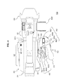
- FIG. 4 is a plan view of the imaging system.
- FIG. 5 is a diagram illustrating functional blocks of an imaging system.
- FIG. 6 is a diagram illustrating a mount section of an imaging device.
- FIG. 7 is a diagram illustrating a mount section of a camera grip.
- FIG. 8 is a diagram illustrating a disassembled perspective view of constituent elements including mount sections of an imaging device and a camera grip.
- FIG. 9 is a diagram illustrating a cable arrangement in an imaging device.
- FIG. 10 is a diagram illustrating a cable arrangement in a camera grip.
- FIG. 11 is a diagram illustrating cases where the positional relationship between an imaging device and a camera grip is changed.
- FIG. 12 is a diagram for describing a chrysanthemum-shaped metal fixture.
- FIG. 13 is a diagram illustrating another configuration of the mount section of the imaging device.
- FIG. 1 to FIG. 4 illustrate external appearances of an imaging system of the present technology.
- FIG. 1 is a right side view of the imaging system.
- FIG. 2 is a front view of the imaging system.
- FIG. 3 is a back view of the imaging system.
- FIG. 4 is a plan view of the imaging system.
- An imaging system 10 includes a lens unit 20 , an imaging device 30 , and a camera grip 60 .
- the camera grip 60 is provided in an attachable and detachable manner to the imaging device 30 , and may be provided separately from the imaging device 30 .
- the lens unit 20 is attached to the front surface of the imaging device 30 .
- the lens unit 20 includes an imaging lens that condenses light from a subject, a zoom mechanism that allows the optical magnification of the imaging lens to change in a prescribed range, etc.
- a handle section 331 is formed on the upper surface of the imaging device 30 .
- the handle section 331 is provided such that, when a user carries the imaging system 10 around or uses the imaging system 10 in a low position, the user can grip the handle section 331 with a hand to hold the imaging system 10 .
- a microphone attachment section 332 is provided on the right side surface on the front end side of the handle section 331 .
- a viewfinder section 34 is provided on the rear side of the upper surface of the imaging device 30 . The viewfinder section 34 displays a camera-through image, an image recorded on a recording medium, a menu image, various pieces of information, etc.
- a battery 80 that supplies electric power necessary to cause the imaging system 10 to operate is mounted on the rear surface of the imaging device 30 . Further, a manipulation section 32 including various manipulation switches is provided on the upper surface, the left side surface, and the back surface of the imaging device 30 .
- a mount section 35 for attaching the camera grip 60 in an attachable and detachable manner is provided on the right side surface of the imaging device 30 . Further, a jack that attaches a connection cable for electrically connecting the imaging device 30 and the camera grip 60 is provided in the vicinity of the mount section 35 . Note that details of the mount section and the connection cable are described later.
- the camera grip 60 includes a grip main body section 61 and a mount section 65 .
- the grip main body section 61 is a portion that the user grasps, and is in a shape that can be easily grasped by the user's hand.
- a manipulation section 62 is provided in a position where it can be manipulated in a state where the user grasps the grip main body section 61 .
- a zoom switch 621 that adjusts the focal distance and a REC button 622 that gives an instruction to start or end recording are provided in the manipulation section 62 .
- assignable buttons 623 and 624 of which the function can be changed and a setting button 625 for assigning functions to assignable buttons and changing functions assigned to assignable buttons are provided in the manipulation section 62 .
- a jog dial 626 or the like for selecting functions etc. is provided in the manipulation section 62 .
- a lock release button 627 capable of adjusting the position of the grip main body section 61 with respect to the mount section 65 is provided in the grip main body section 61 .
- the grip main body section 61 becomes rotationally movable in the direction of arrow MA with the mount section 65 as the axis; if lock release manipulation is then ended, the position of the grip main body section 61 is fixed at the rotational movement position at the time of the end. Therefore, if the lock release button 627 is manipulated in a state where the camera grip 60 is mounted on the imaging device 30 , the position of the grip main body section 61 can be adjusted to a desired direction with respect to the imaging device 30 .
- the grip main body section 61 is provided with a connection cable 75 for electrically connecting the grip main body section 61 to the imaging device 30 .
- a plug is provided at the tip of the connection cable 75 .
- FIG. 5 is a diagram illustrating functional blocks of an imaging system.
- the imaging device 30 includes an imaging section 301 , a video signal processing section 302 , an audio signal processing section 303 , a recording and reproducing section 304 , a lens driving section 305 , a control section 310 , a power source section 315 , the manipulation section 32 , the battery 80 , a recording medium 86 , etc.
- the camera grip 60 includes the manipulation section 62 , as described above.
- the imaging section 301 includes, for example, an imaging element such as a complementary metal oxide semiconductor device (CMOS) or a charge-coupled device (CCD).
- CMOS complementary metal oxide semiconductor device
- CCD charge-coupled device
- the imaging section 301 photoelectrically converts an optical image that is formed on an imaging surface by the lens unit 20 and generates an imaging signal, and outputs the imaging signal to the video signal processing section 302 .
- the video signal processing section 302 performs, on an imaging signal, denoising processing, gain adjustment processing, and the processing of adjusting luminance and color. Further, the video signal processing section 302 performs processing that converts a video signal after adjustment processing and a video signal read by the recording and reproducing section 304 to a video signal corresponding to the number of pixels of the viewfinder section 34 and processing that superimposes a display signal of a menu display or the like on a video signal. Further, in order to obtain a desired captured image easily, the video signal processing section 302 may perform video image processing on a viewfinder image, such as enlarging and displaying a central portion. The video signal processing section 302 outputs a video signal after processing to the viewfinder section 34 .
- the audio signal processing section 303 performs the processing of amplifying an audio signal generated by a microphone, etc., and outputs the amplified audio signal to the recording and reproducing section 304 .
- the recording and reproducing section 304 performs, on the basis of an instruction from the control section 310 , the processing of recording an information signal such as a video signal or an audio signal on the recording medium 86 and the processing of reading and reproducing an information signal recorded on the recording medium 86 . Further, the recording and reproducing section 304 performs the processing of supplying a video signal read from the recording medium 86 to the viewfinder section 34 via the video signal processing section 302 , or the like. Furthermore, the recording and reproducing section 304 performs the processing of outputting an information signal in a prescribed format to an external device, or the like.
- the recording medium 86 may be an attachable and detachable recording medium, or may be a recording medium fixedly provided in the interior of the imaging device 30 .
- the lens driving section 305 drives the lens unit 20 and sets the lens unit 20 to a desired zoom magnification on the basis of an instruction from the control section 310 . Further, the lens driving section 305 may perform focus adjustment so that an optical image bonded to the imaging surface of the imaging element in the imaging section 301 is a clear image.
- the manipulation section 32 includes manipulation switches provided on the side surface, the back surface, and the upper surface of the imaging device 30 .
- the manipulation section 32 generates a manipulation signal in accordance with the user's switch manipulation, and outputs the manipulation signal to the control section 310 .
- the manipulation section 62 includes manipulation switches provided in the grip main body section 61 of the camera grip 60 .
- the manipulation section 62 is electrically connected to the imaging device 30 via the connection cable 75 .
- the manipulation section 62 generates a manipulation signal in accordance with the user's switch manipulation, and outputs the manipulation signal to the control section 310 .
- the control section 310 includes, for example, a central processing unit (CPU), an electrically erasable programmable ROM (EEPROM), a read-only memory (ROM), a random access memory (RAM), etc., which are not illustrated.
- a program for executing various pieces of control processing in the control section 310 is stored in the ROM in the control section 310 .
- the CPU operates on the basis of the program, and executes calculation and control processing necessary for each piece of control while using the RAM.
- the program is not limited to a case of being stored in a ROM incorporated in the imaging device 30 in advance; and may be stored in a removable recording medium and provided to the imaging device 30 , or may be downloaded on the imaging device 30 via a network such as a LAN or the Internet.
- the control section 310 controls each section on the basis of user manipulation or the like on the manipulation sections 32 and 62 so that an operation in accordance with the user manipulation is performed in the imaging system 10 .
- the control section 310 turns on and off the power source of the imaging system 10 on the basis of, for example, user manipulation on a power supply switch.
- the control section 310 controls the lens driving section 305 on the basis of user manipulation on a zoom switch, and causes the focal distance of the lens unit 20 to change in accordance with the user manipulation.
- the control section 310 causes the recording of an information signal to be started or stopped on the basis of user manipulation on a REC button.
- control section 310 performs the control of executing a function assigned to a manipulated assignable button on the basis of user manipulation on the assignable button. Furthermore, the control section 310 assigns a function to an assignable button on the basis of user manipulation on a setting button. Note that, for example, a function of displaying various markers, a rec review function, a function of switching the mode of the viewfinder section, a viewfinder image switching function for facilitating focus adjustment, a function of displaying information regarding luminance, etc. are assignable to assignable buttons.
- the power source section 315 supplies electric power from the battery 80 mounted on the imaging device 30 to each section of the imaging system 10 .
- FIG. 6 illustrates a mount section of an imaging device
- FIG. 7 illustrates a mount section of a camera grip
- FIG. 8 illustrates a disassembled perspective view of constituent elements configuring mount sections of an imaging device and a camera grip.
- a mount base section 352 in a ring shape is fitted to a circular concave section 351 formed on the right side surface.
- Bayonet tabs 352 a are protrusively formed on the inner peripheral surface of the mount base section 352 .
- a leaf spring section 353 formed in a ring shape is provided between the bottom surface of the circular concave section 351 and the mount base section 352 .
- elastic pieces 353 a protruding toward the mount base section 352 are provided in positions facing the bayonet tabs 352 a .
- the elastic pieces 353 a bias bayonet tabs 652 a of the mount section 65 inserted between the elastic pieces 353 a and the bayonet tabs 352 a so as to press the bayonet tabs 652 a against the bayonet tabs 352 a .
- An appearance ring 354 is provided on the outside surface of the mount base section 352 (the front surface of the circular concave section 351 ) in order to make the appearance of the mount section 35 better.
- threaded holes 352 b , 353 b , and 354 b for stacking the mount base section 352 , the leaf spring section 353 , and the appearance ring 354 and fixing the mount base section 352 , the leaf spring section 353 , and the appearance ring 354 to the circular concave section 351 with a screw are provided in the mount base section 352 , the leaf spring section 353 , and the appearance ring 354 , respectively.
- the mount section 65 is provided on a facing surface 61 a of the grip main body section 61 facing the imaging device 30 .
- the mount section 65 includes a mount base section 651 in a circular cylindrical shape that protrudes from the facing surface 61 a toward the imaging device and a mount main body section 652 in a circular cylindrical shape that is provided on the tip side of the mount base section 651 .
- the bayonet tabs 652 a are protrusively formed on the outer peripheral surface of a tip portion of the mount main body section 652 . Note that the number of bayonet tabs in the mount sections 35 and 65 is not limited to three, and less than three or more than three bayonet tabs may be provided.
- a lock mechanism (not illustrated) is provided to regulate the rotation of the mount section 65 of the camera grip 60 with respect to the mount section 35 of the imaging device 30 when the camera grip 60 is mounted on the imaging device 30 . Therefore, rotation of the mount section 65 relative to the mount section 35 during the manipulation of the camera grip 60 and falling off or the like of the camera grip 60 from the imaging device 30 can be prevented.
- a lock pin may be provided in the mount section 35
- an engagement hole may be provided in the mount main body section 652 .
- the user sets the position of the bayonet tab 652 a of the mount section 65 in the camera grip 60 between bayonet tabs 352 a of the mount section 35 in the imaging device 30 . Furthermore, in the state where the position is set, the user inserts the mount main body section 652 of the camera grip 60 into the circular concave section 351 of the imaging device 30 . After that, the user rotates the mount main body section 652 of which the bayonet tabs 652 a are inserted in prescribed positions that are positions on the deeper side than the bayonet tabs 352 a , with the insertion direction as the rotation axis.
- the bayonet tab 652 a is in a state of being engaged with (a state of overlapping with) the bayonet tab 352 a , and a state where the mount section 35 and the mount section 65 are linked is created. That is, a state where the camera grip 60 is fixed to the imaging device 30 is created. Furthermore, the configuration is made such that, if the mount section 65 is rotated up to a prescribed position whereby the bayonet tab 652 a and the bayonet tab 352 a are engaged, the lock pin of the mount section 35 is inserted into the engagement hole of the mount main body section 652 . By thus providing a lock mechanism, the mount section 65 of the camera grip 60 can be fixed to the mount section 35 . Further, if the manipulation of pulling out the lock pin from the engagement hole is performed, the mount section 65 can be rotationally moved relative to the mount section 35 , and the camera grip can be detached from the imaging device 30 .
- the attachment and detachment of the imaging device 30 and the camera grip 60 can be performed quickly and easily with the mount section having a bayonet structure. Further, by providing a lock mechanism in the above manner, the linkage state of the mount section 35 and the mount section 65 is maintained until lock release manipulation, such as user manipulation that releases the engagement state of the lock pin and the engagement hole, is performed. Therefore, the falling off and the like of the camera grip 60 from the imaging device 30 can be prevented with reliability.
- the mount section 35 can hold the mount section 65 without causing unsteadiness or the like in a state where the bayonet tab 652 a and the bayonet tab 352 a are engaged.
- the mount sections 35 and 65 are not limited to a bayonet structure in which a bayonet tab is formed in each of the mount sections 35 and 65 , and the mount section 35 and the mount section 65 are linked in a state where both bayonet tabs are engaged (overlap).
- a bayonet structure in which a bayonet tab is formed in one mount section and an engagement section overlapping with the bayonet tab is provided in another mount section, and thereby the mount sections can be linked may be used.
- connection cable 75 The electrical connection between the imaging device and the camera grip in the imaging system is made using the connection cable 75 , as described above.
- the grip main body section 61 of the camera grip is provided in a rotationally movable manner in the direction of arrow MA of FIG. 1 with the mount section 65 as the axis.
- the imaging system 10 is provided such that, even if the position of the grip main body section 61 is changed with respect to the imaging device 30 , the connection cable 75 does not become an obstacle to the switch manipulation of the grip main body section 61 .
- a situation where the connection cable 75 sags greatly and becomes an obstacle to switch manipulation etc. is avoided by providing the connection cable 75 such that the connection cable 75 is wound or rewound around the mount section 65 in accordance with the rotational movement in the direction of arrow MA of the grip main body section 61 .
- FIG. 9 illustrates a cable arrangement in an imaging device.
- the cable direction of the connection cable 75 is set to a tangential direction to the mount section 35 .
- a jack 36 into which a plug 76 provided at the connection cable 75 is inserted is provided on the right side surface of the imaging device 30 , which is a surface to be attached to the camera grip 60 . Further, for the jack 36 , the insertion and removal direction of the plug is set to the direction of arrow FB that causes the cable direction to be an upper tangent line to the mount section 35 .
- FIG. 10 illustrates a cable arrangement in a camera grip.
- the connection cable 75 is drawn out from the facing surface 61 a of the grip main body section 61 facing the imaging device.
- a cable guide section that regulates the position of the connection cable 75 to a direction winding around the mount section 65 is provided on the facing surface 61 a .
- As the cable guide section a cable guide protrusion section and/or a cable guide trench section is provided.
- a cable guide protrusion section 67 is formed such that the position of the connection cable 75 is regulated to a winding direction FG with respect to the mount section 65 by the mount section 65 and the cable guide protrusion section 67 .
- the cable guide protrusion section 67 is formed in the circumferential direction of the mount section 65 in a position distant from the edge of the mount section 65 by a prescribed spacing in accordance with the thickness of the connection cable so as to protrude in the protrusion direction of the mount section 65 .
- a cable guide trench section 68 is formed in a portion that is around the mount base section 651 and that has a large amount of protrusion toward the imaging device.
- the cable guide trench section 68 is formed in the circumferential direction of the mount section 65 so as to have, as the trench width, the length from the edge of the mount section 65 to a position distant a prescribed spacing in accordance with the thickness of the connection cable.
- the position of the connection cable 75 is regulated by the mount section 65 , the cable guide protrusion section 67 , and the cable guide trench section 68 .
- FIG. 11 illustrates cases where the positional relationship between the imaging device and the camera grip is changed.
- (a) of FIG. 11 illustrates the position of the connection cable 75 in a case of an imaging position in which the imaging direction is, for example, the horizontal direction.
- (b) of FIG. 11 illustrates the position of the connection cable 75 in a case of an imaging position in which the imaging direction is the downward direction.
- (c) of FIG. 11 illustrates the position of the connection cable 75 in a case of an imaging position in which the imaging direction is the upward direction.
- the positional relationship between the imaging device 30 and the camera grip 60 can be changed by manipulating the lock release button 627 (see FIG. 4 ) of the camera grip 60 .
- the grip main body section 61 becomes rotationally movable with the mount section 65 as the axis. Further, if the user ends lock release manipulation, the position of the grip main body section 61 is fixed at the rotational movement position at the time of the end.
- the mount section 35 of the imaging device 30 and the mount section 65 of the camera grip 60 are fixed to each other. Thus, the positional relationship between the imaging device 30 and the camera grip 60 can be adjusted by manipulating the lock release button 627 .
- the imaging system 10 is provided such that, when the camera grip 60 is mounted on the imaging device 30 , the cable direction in the imaging device 30 is a cable direction regulated by a cable position regulation section of the camera grip 60 . Further, in the imaging system 10 , the winding or rewinding of the connection cable 75 to the mount section 65 is performed in accordance with the rotational movement of the grip main body section 61 ; thereby, even if the positional relationship between the imaging device and the camera grip is changed, the connection cable 75 is prevented from sagging greatly.
- the imaging device 30 is rotated in the direction of arrow PD relative to the camera grip 60 and the imaging direction is changed from the horizontal direction to the downward direction, also the position of the plug 76 inserted in the jack moves in the direction of arrow PD, with the mount section 35 as the rotational movement axis.
- the plug 76 moves in the direction of arrow PD, the winding of the connection cable 75 to the mount section 65 becomes larger than in a case where the imaging direction is the horizontal direction, and the connection cable 75 does not sag greatly.
- the imaging device 30 is rotated in the direction of arrow PU relative to the camera grip 60 and the imaging direction is changed from the horizontal direction to the upward direction, also the position of the plug 76 inserted in the jack moves in the direction of arrow PU, with the mount section 35 as the rotational movement axis.
- the connection cable 75 is rewound from the mount section 65 . Therefore, the imaging device 30 and the camera grip 60 can be connected without the connection cable 75 sagging greatly.
- connection cable 75 does not become an obstacle to the user's switch manipulation etc., and the manipulability of the imaging device can be kept good regardless of the change in the imaging position.
- an attachment surface includes a chrysanthemum-shaped metal fixture (a rosette surface). Further, also a chrysanthemum-shaped metal fixture adapter or the like in which one surface is a chrysanthemum-shaped metal fixture and a section for attaching an accessory is provided on the other surface side, and the like are used.
- FIG. 12 is a diagram for describing a chrysanthemum-shaped metal fixture. Note that (a) of FIG. 12 shows a front view and (b) of FIG. 12 shows a perspective view.
- a chrysanthemum-shaped metal fixture 356 includes a plurality of convex surfaces 356 a and a plurality of concave surfaces 356 b extending radially from the center of a bearing surface. Further, an insertion hole 356 c through which a fixing screw for fixing, to an imaging device, an accessory or the like equipped with a chrysanthemum-shaped metal fixture is inserted is formed in a central portion of the bearing surface. Furthermore, attachment holes 356 d for attaching the chrysanthemum-shaped metal fixture 356 to the main body of an accessory or the like are provided in the chrysanthemum-shaped metal fixture 356 .
- FIG. 13 illustrates another configuration of the mount section of the imaging device.
- the mount base section 352 in a ring-like shape is provided on the circular concave section 351 formed on the right side surface.
- the bayonet tabs 352 a are protrusively formed on the inner peripheral surface of the mount base section 352 .
- the leaf spring section 353 formed in a ring-like shape is provided between the circular concave section 351 and the mount base section 352 , and the appearance ring 354 is provided on the outside surface of the mount base section 352 .
- the chrysanthemum-shaped metal fixture 356 is provided at the center of the bottom surface of the interior of the mount section 35 , that is, the circular concave section 351 .
- a threaded hole for fixation 357 for fixing an accessory or the like to the imaging device is formed at the center of the chrysanthemum-shaped metal fixture 356 .
- the mount section 35 is formed in this way, an accessory or the like including a chrysanthemum-shaped metal fixture can be attached in a case where the camera grip 60 is detached from the imaging device 30 .
- the chrysanthemum-shaped metal fixture 356 of the mount section 35 and a chrysanthemum-shaped metal fixture provided on an attachment surface of an accessory or the like are faced to each other, and a fixing screw provided at the center of the chrysanthemum-shaped metal fixture in the accessory or the like is screwed into the threaded hole for fixation 357 of the mount section 35 .
- the convex section of one chrysanthemum-shaped metal fixture is fitted to the concave section of the other chrysanthemum-shaped metal fixture, and the imaging device and the accessory or the like can be fixed with reliability. Further, if the fixing screw is loosened to release the fitting state of the concave section and the convex section of the chrysanthemum-shaped metal fixtures, the accessory or the like becomes rotationally movable with the fixing screw as the rotation axis, and the accessory or the like can be changed to a desired position with respect to the imaging device.
- present technology may also be configured as below.
- An imaging device including
- the imaging device according to (1) or (2), further including
- the imaging device according to any one of (1) to (3), further including:
- a mount section on which the camera grip is mounted in an attachable and detachable manner is provided in the imaging device, and a mount section on which the imaging device is mounted in an attachable and detachable manner is provided in the camera grip; and the mount sections each have a bayonet mechanism. Therefore, the attachment and detachment of the imaging device and the camera grip becomes easier and manipulability can be improved; thus, this technology is suitable for, for example, commercial video cameras and the like.
Landscapes
- Physics & Mathematics (AREA)
- General Physics & Mathematics (AREA)
- Engineering & Computer Science (AREA)
- Multimedia (AREA)
- Signal Processing (AREA)
- Studio Devices (AREA)
- Structure And Mechanism Of Cameras (AREA)
- Accessories Of Cameras (AREA)
- Camera Bodies And Camera Details Or Accessories (AREA)
Applications Claiming Priority (3)
| Application Number | Priority Date | Filing Date | Title |
|---|---|---|---|
| JP2015-173820 | 2015-09-03 | ||
| JP2015173820 | 2015-09-03 | ||
| PCT/JP2016/070866 WO2017038272A1 (ja) | 2015-09-03 | 2016-07-14 | 撮像装置とカメラグリップおよび撮像システム |
Related Parent Applications (1)
| Application Number | Title | Priority Date | Filing Date |
|---|---|---|---|
| PCT/JP2016/070866 A-371-Of-International WO2017038272A1 (ja) | 2015-09-03 | 2016-07-14 | 撮像装置とカメラグリップおよび撮像システム |
Related Child Applications (1)
| Application Number | Title | Priority Date | Filing Date |
|---|---|---|---|
| US16/284,700 Continuation US10788737B2 (en) | 2015-09-03 | 2019-02-25 | Imaging device and camera grip, and imaging system |
Publications (2)
| Publication Number | Publication Date |
|---|---|
| US20180164663A1 US20180164663A1 (en) | 2018-06-14 |
| US10254633B2 true US10254633B2 (en) | 2019-04-09 |
Family
ID=58188316
Family Applications (3)
| Application Number | Title | Priority Date | Filing Date |
|---|---|---|---|
| US15/580,389 Active US10254633B2 (en) | 2015-09-03 | 2016-07-14 | Imaging device and camera grip, and imaging system |
| US16/284,700 Active US10788737B2 (en) | 2015-09-03 | 2019-02-25 | Imaging device and camera grip, and imaging system |
| US17/020,765 Abandoned US20200409243A1 (en) | 2015-09-03 | 2020-09-14 | Imaging device and camera grip, and imaging system |
Family Applications After (2)
| Application Number | Title | Priority Date | Filing Date |
|---|---|---|---|
| US16/284,700 Active US10788737B2 (en) | 2015-09-03 | 2019-02-25 | Imaging device and camera grip, and imaging system |
| US17/020,765 Abandoned US20200409243A1 (en) | 2015-09-03 | 2020-09-14 | Imaging device and camera grip, and imaging system |
Country Status (4)
| Country | Link |
|---|---|
| US (3) | US10254633B2 (ja) |
| JP (1) | JP6760292B2 (ja) |
| CN (1) | CN107924112B (ja) |
| WO (1) | WO2017038272A1 (ja) |
Families Citing this family (14)
| Publication number | Priority date | Publication date | Assignee | Title |
|---|---|---|---|---|
| JP6833583B2 (ja) * | 2017-03-24 | 2021-02-24 | キヤノン株式会社 | 電子機器 |
| EP3410201B1 (en) | 2017-05-31 | 2020-03-11 | Canon Kabushiki Kaisha | Accessory, image pickup apparatus on which same is mountable, and camera system |
| RU2747716C2 (ru) | 2017-05-31 | 2021-05-13 | Кэнон Кабусики Кайся | Аксессуар, устройство захвата изображений, на котором он может устанавливаться, и система камеры |
| SG10202103518RA (en) | 2017-05-31 | 2021-05-28 | Canon Kk | Adapter device, imaging apparatus, and accessory |
| JP6743090B2 (ja) | 2017-05-31 | 2020-08-19 | キヤノン株式会社 | 撮像装置およびアクセサリ |
| TWI771631B (zh) | 2017-05-31 | 2022-07-21 | 日商佳能股份有限公司 | 安裝設備及用於成像設備的配件 |
| RU2755029C2 (ru) | 2017-05-31 | 2021-09-10 | Кэнон Кабусики Кайся | Аксессуар, устройство захвата изображений, на котором он может устанавливаться, и система камеры |
| US10613419B2 (en) | 2017-05-31 | 2020-04-07 | Canon Kabushiki Kaisha | Imaging apparatus and accessory |
| EP3410202B1 (en) | 2017-05-31 | 2020-01-01 | Canon Kabushiki Kaisha | Accessory, image pickup apparatus on which same is mountable, and camera system |
| JP1613026S (ja) * | 2017-12-28 | 2018-09-10 | ||
| JP6980576B2 (ja) * | 2018-03-19 | 2021-12-15 | キヤノン株式会社 | 撮像装置 |
| JP2020173356A (ja) * | 2019-04-11 | 2020-10-22 | パナソニックIpマネジメント株式会社 | 撮像装置 |
| CN113944846B (zh) * | 2021-11-04 | 2022-04-08 | 郭佳泷 | 一种基于云计算的智能化土木工程监测装置 |
| DE102022122890A1 (de) * | 2022-09-09 | 2024-03-14 | Valeo Schalter Und Sensoren Gmbh | Erfassungsvorrichtung für ein Fahrzeug, sowie Erfassungssystem und Verfahren zum Verbinden eines elektrischen Steckers des Erfassungssystems |
Citations (6)
| Publication number | Priority date | Publication date | Assignee | Title |
|---|---|---|---|---|
| JPH1023306A (ja) | 1996-06-28 | 1998-01-23 | Hitachi Ltd | 延長ケーブル |
| JP2005181718A (ja) | 2003-12-19 | 2005-07-07 | Olympus Corp | カメラグリップ及びカメラ |
| US20070166027A1 (en) | 2006-01-19 | 2007-07-19 | Fujifilm Corporation | Camera |
| JP2007194952A (ja) | 2006-01-19 | 2007-08-02 | Fujifilm Corp | カメラ |
| US20130108254A1 (en) * | 2011-10-26 | 2013-05-02 | Canon Kabushiki Kaisha | Image-pickup apparatus, camera grip, and image-pickup system |
| JP2013092678A (ja) | 2011-10-26 | 2013-05-16 | Canon Inc | 撮像装置、カメラグリップ及び撮像システム |
Family Cites Families (5)
| Publication number | Priority date | Publication date | Assignee | Title |
|---|---|---|---|---|
| CN2187804Y (zh) * | 1994-03-10 | 1995-01-18 | 沈伟宏 | 双管云台回转卡扣装置 |
| DE19534231C2 (de) * | 1995-09-15 | 1998-04-16 | Rollei Fototechnic Gmbh | Kamerasystem |
| JP2002082231A (ja) * | 2000-09-11 | 2002-03-22 | Auto Network Gijutsu Kenkyusho:Kk | 光ファイバガイド装置 |
| JP2005018171A (ja) | 2003-06-23 | 2005-01-20 | Ricoh Co Ltd | 色領域作成プログラム |
| CN201514530U (zh) * | 2009-09-22 | 2010-06-23 | 凤凰光学股份有限公司 | 一种照相机镜头卡口夹具 |
-
2016
- 2016-07-14 CN CN201680048763.0A patent/CN107924112B/zh active Active
- 2016-07-14 US US15/580,389 patent/US10254633B2/en active Active
- 2016-07-14 JP JP2017537637A patent/JP6760292B2/ja active Active
- 2016-07-14 WO PCT/JP2016/070866 patent/WO2017038272A1/ja active Application Filing
-
2019
- 2019-02-25 US US16/284,700 patent/US10788737B2/en active Active
-
2020
- 2020-09-14 US US17/020,765 patent/US20200409243A1/en not_active Abandoned
Patent Citations (6)
| Publication number | Priority date | Publication date | Assignee | Title |
|---|---|---|---|---|
| JPH1023306A (ja) | 1996-06-28 | 1998-01-23 | Hitachi Ltd | 延長ケーブル |
| JP2005181718A (ja) | 2003-12-19 | 2005-07-07 | Olympus Corp | カメラグリップ及びカメラ |
| US20070166027A1 (en) | 2006-01-19 | 2007-07-19 | Fujifilm Corporation | Camera |
| JP2007194952A (ja) | 2006-01-19 | 2007-08-02 | Fujifilm Corp | カメラ |
| US20130108254A1 (en) * | 2011-10-26 | 2013-05-02 | Canon Kabushiki Kaisha | Image-pickup apparatus, camera grip, and image-pickup system |
| JP2013092678A (ja) | 2011-10-26 | 2013-05-16 | Canon Inc | 撮像装置、カメラグリップ及び撮像システム |
Non-Patent Citations (1)
| Title |
|---|
| International Search Report dated Oct. 11, 2016 in PCT/JP2016/070866. |
Also Published As
| Publication number | Publication date |
|---|---|
| JP6760292B2 (ja) | 2020-09-23 |
| US20180164663A1 (en) | 2018-06-14 |
| US10788737B2 (en) | 2020-09-29 |
| US20190187540A1 (en) | 2019-06-20 |
| JPWO2017038272A1 (ja) | 2018-06-14 |
| US20200409243A1 (en) | 2020-12-31 |
| WO2017038272A1 (ja) | 2017-03-09 |
| CN107924112B (zh) | 2021-03-23 |
| CN107924112A (zh) | 2018-04-17 |
Similar Documents
| Publication | Publication Date | Title |
|---|---|---|
| US10788737B2 (en) | Imaging device and camera grip, and imaging system | |
| TWI602011B (zh) | 成像單元及安裝裝置 | |
| US20170041516A1 (en) | Attachable smartphone camera | |
| JP6580210B2 (ja) | アクセサリ及びこれを装着可能な撮像装置、撮像システム | |
| US20130100344A1 (en) | Accessory and imaging device | |
| JP2018205727A (ja) | アクセサリ及びこれを装着可能な撮像装置、カメラシステム | |
| TW201504709A (zh) | 成像裝置 | |
| WO2015114934A1 (ja) | カメラおよびアダプタ | |
| JP2024061919A (ja) | レンズマウント及びこれを装着可能なカメラマウント、マウントシステム | |
| JP2015186056A (ja) | 撮像装置 | |
| US10761411B2 (en) | Imaging apparatus with user holdable grip | |
| US9817300B2 (en) | System camera lens adaptor | |
| US11550207B2 (en) | Image capturing apparatus, accessory, camera system including image capturing apparatus and accessory | |
| JP2007194951A (ja) | カメラ | |
| JP5697718B2 (ja) | 電子機器 | |
| JP2019120938A (ja) | 撮像装置 | |
| JP7183013B2 (ja) | 撮像装置 | |
| JP2022160332A (ja) | 装置および撮像システム | |
| JP2016045477A (ja) | カメラ | |
| JP2010186049A (ja) | 撮影レンズ及びカメラ | |
| JP2015018167A (ja) | 撮像装置 | |
| JP2017139103A (ja) | 電子機器 | |
| JP2009042471A (ja) | 撮像装置 | |
| JP2015204243A (ja) | 撮像装置 | |
| JP2013092665A (ja) | アクセサリ機器 |
Legal Events
| Date | Code | Title | Description |
|---|---|---|---|
| AS | Assignment |
Owner name: SONY CORPORATION, JAPAN Free format text: ASSIGNMENT OF ASSIGNORS INTEREST;ASSIGNORS:ISHIDA, JUN;IZUMI, KOJI;REEL/FRAME:044754/0507 Effective date: 20171124 |
|
| FEPP | Fee payment procedure |
Free format text: ENTITY STATUS SET TO UNDISCOUNTED (ORIGINAL EVENT CODE: BIG.); ENTITY STATUS OF PATENT OWNER: LARGE ENTITY |
|
| STCF | Information on status: patent grant |
Free format text: PATENTED CASE |
|
| MAFP | Maintenance fee payment |
Free format text: PAYMENT OF MAINTENANCE FEE, 4TH YEAR, LARGE ENTITY (ORIGINAL EVENT CODE: M1551); ENTITY STATUS OF PATENT OWNER: LARGE ENTITY Year of fee payment: 4 |