US10099159B2 - Oil separator and drain discharge system - Google Patents
Oil separator and drain discharge system Download PDFInfo
- Publication number
- US10099159B2 US10099159B2 US15/121,202 US201515121202A US10099159B2 US 10099159 B2 US10099159 B2 US 10099159B2 US 201515121202 A US201515121202 A US 201515121202A US 10099159 B2 US10099159 B2 US 10099159B2
- Authority
- US
- United States
- Prior art keywords
- liquid
- air
- oil
- oil separator
- discharge port
- Prior art date
- Legal status (The legal status is an assumption and is not a legal conclusion. Google has not performed a legal analysis and makes no representation as to the accuracy of the status listed.)
- Active, expires
Links
Images


Classifications
-
- B—PERFORMING OPERATIONS; TRANSPORTING
- B01—PHYSICAL OR CHEMICAL PROCESSES OR APPARATUS IN GENERAL
- B01D—SEPARATION
- B01D19/00—Degasification of liquids
- B01D19/0063—Regulation, control including valves and floats
-
- B—PERFORMING OPERATIONS; TRANSPORTING
- B01—PHYSICAL OR CHEMICAL PROCESSES OR APPARATUS IN GENERAL
- B01D—SEPARATION
- B01D45/00—Separating dispersed particles from gases or vapours by gravity, inertia, or centrifugal forces
- B01D45/04—Separating dispersed particles from gases or vapours by gravity, inertia, or centrifugal forces by utilising inertia
-
- B—PERFORMING OPERATIONS; TRANSPORTING
- B01—PHYSICAL OR CHEMICAL PROCESSES OR APPARATUS IN GENERAL
- B01D—SEPARATION
- B01D53/00—Separation of gases or vapours; Recovering vapours of volatile solvents from gases; Chemical or biological purification of waste gases, e.g. engine exhaust gases, smoke, fumes, flue gases, aerosols
- B01D53/02—Separation of gases or vapours; Recovering vapours of volatile solvents from gases; Chemical or biological purification of waste gases, e.g. engine exhaust gases, smoke, fumes, flue gases, aerosols by adsorption, e.g. preparative gas chromatography
- B01D53/04—Separation of gases or vapours; Recovering vapours of volatile solvents from gases; Chemical or biological purification of waste gases, e.g. engine exhaust gases, smoke, fumes, flue gases, aerosols by adsorption, e.g. preparative gas chromatography with stationary adsorbents
-
- B—PERFORMING OPERATIONS; TRANSPORTING
- B01—PHYSICAL OR CHEMICAL PROCESSES OR APPARATUS IN GENERAL
- B01D—SEPARATION
- B01D53/00—Separation of gases or vapours; Recovering vapours of volatile solvents from gases; Chemical or biological purification of waste gases, e.g. engine exhaust gases, smoke, fumes, flue gases, aerosols
- B01D53/26—Drying gases or vapours
- B01D53/261—Drying gases or vapours by adsorption
-
- B—PERFORMING OPERATIONS; TRANSPORTING
- B60—VEHICLES IN GENERAL
- B60G—VEHICLE SUSPENSION ARRANGEMENTS
- B60G17/00—Resilient suspensions having means for adjusting the spring or vibration-damper characteristics, for regulating the distance between a supporting surface and a sprung part of vehicle or for locking suspension during use to meet varying vehicular or surface conditions, e.g. due to speed or load
- B60G17/02—Spring characteristics, e.g. mechanical springs and mechanical adjusting means
- B60G17/04—Spring characteristics, e.g. mechanical springs and mechanical adjusting means fluid spring characteristics
- B60G17/0408—Spring characteristics, e.g. mechanical springs and mechanical adjusting means fluid spring characteristics details, e.g. antifreeze for suspension fluid, pumps, retarding means per se
-
- B—PERFORMING OPERATIONS; TRANSPORTING
- B60—VEHICLES IN GENERAL
- B60T—VEHICLE BRAKE CONTROL SYSTEMS OR PARTS THEREOF; BRAKE CONTROL SYSTEMS OR PARTS THEREOF, IN GENERAL; ARRANGEMENT OF BRAKING ELEMENTS ON VEHICLES IN GENERAL; PORTABLE DEVICES FOR PREVENTING UNWANTED MOVEMENT OF VEHICLES; VEHICLE MODIFICATIONS TO FACILITATE COOLING OF BRAKES
- B60T17/00—Component parts, details, or accessories of power brake systems not covered by groups B60T8/00, B60T13/00 or B60T15/00, or presenting other characteristic features
- B60T17/002—Air treatment devices
- B60T17/004—Draining and drying devices
-
- F—MECHANICAL ENGINEERING; LIGHTING; HEATING; WEAPONS; BLASTING
- F04—POSITIVE - DISPLACEMENT MACHINES FOR LIQUIDS; PUMPS FOR LIQUIDS OR ELASTIC FLUIDS
- F04B—POSITIVE-DISPLACEMENT MACHINES FOR LIQUIDS; PUMPS
- F04B39/00—Component parts, details, or accessories, of pumps or pumping systems specially adapted for elastic fluids, not otherwise provided for in, or of interest apart from, groups F04B25/00 - F04B37/00
- F04B39/04—Measures to avoid lubricant contaminating the pumped fluid
-
- F—MECHANICAL ENGINEERING; LIGHTING; HEATING; WEAPONS; BLASTING
- F04—POSITIVE - DISPLACEMENT MACHINES FOR LIQUIDS; PUMPS FOR LIQUIDS OR ELASTIC FLUIDS
- F04B—POSITIVE-DISPLACEMENT MACHINES FOR LIQUIDS; PUMPS
- F04B39/00—Component parts, details, or accessories, of pumps or pumping systems specially adapted for elastic fluids, not otherwise provided for in, or of interest apart from, groups F04B25/00 - F04B37/00
- F04B39/16—Filtration; Moisture separation
-
- B—PERFORMING OPERATIONS; TRANSPORTING
- B01—PHYSICAL OR CHEMICAL PROCESSES OR APPARATUS IN GENERAL
- B01D—SEPARATION
- B01D2259/00—Type of treatment
- B01D2259/45—Gas separation or purification devices adapted for specific applications
- B01D2259/4566—Gas separation or purification devices adapted for specific applications for use in transportation means
Definitions
- the present invention relates to an oil separator and a collected liquid discharge system that collect liquid and discharge the collected liquid.
- systems of vehicles such as brakes and suspensions actuate various devices using compressed air.
- Some of such systems include a compressed air drying system located downstream of the compressor to remove water and oil from compressed air.
- An example of a known compressed air drying system includes an air dryer, which includes a desiccant, and an oil separator (for example, see Patent Document 1).
- the oil separator collects liquid that contains oil and water and is discharged from the air dryer by regenerating the desiccant.
- Patent Document 1 Japanese Laid-Open Patent Publication No. 2013-234632
- the conventional oil separators drain the collected liquid by gravity, and thus take a long time to drain the collected liquid.
- an oil separator that separates gas and liquid in fluid containing oil to collect liquid, which contains oil.
- the oil separator includes an oil trap, which traps liquid, a reservoir, which stores the liquid that is trapped by the oil trap, a collected liquid discharge port, which discharges the liquid stored in the reservoir, and a mechanism that increases an internal pressure of the reservoir.
- the oil separator preferably further includes a liquid inlet port, through which liquid flows in, an air discharge port, which discharges air separated from the fluid, and a directional control valve, which is connected to a conduit connected to one of the liquid inlet port and the air discharge port, a gas supply passage, which is connected to a gas supply source, and a liquid discharge passage, which delivers liquid to the oil separator.
- the directional control valve is configured to switch between a first communication state, in which the directional control valve connects the liquid discharge passage to the one of the liquid inlet port and the air discharge port, and a second communication state, in which the directional control valve connects the gas supply passage to the one of the liquid inlet port and the air discharge port.
- the fluid flowing through the directional control valve flows from the liquid discharge passage to the one of the liquid inlet port and the air discharge port.
- the fluid flowing through the directional control valve flows from the gas supply passage to the one of the liquid inlet port and the air discharge port.
- the oil separator preferably further includes an on-off valve, which selectively opens and closes the other one of the liquid inlet port and the air discharge port.
- the on-off valve is closed when the communication state of the directional control valve is in the second communication state.
- the oil separator is preferably configured such that the liquid inlet port is configured to be connected to an air dryer, which includes a desiccant and dries compressed air, and separate gas and liquid in fluid that is discharged from the air dryer and contains oil, thereby collecting liquid, and that the directional control valve is configured to be connected to an air tank, which stores compressed dried air that has flowed out of the air dryer via the gas supply passage.
- an air dryer which includes a desiccant and dries compressed air, and separate gas and liquid in fluid that is discharged from the air dryer and contains oil, thereby collecting liquid
- the directional control valve is configured to be connected to an air tank, which stores compressed dried air that has flowed out of the air dryer via the gas supply passage.
- a collected liquid discharge system includes the above described oil separator and a gas supply source, which supplies gas to the oil separator.
- the directional control valve switches the flow direction in a section upstream of the oil separator such that fluid flows from the liquid discharge passage toward the oil separator.
- the directional control valve switches the flow direction in the section upstream of the oil separator such that gas flows from the gas supply passage toward the oil separator.
- the present invention provides an oil separator and a collected liquid discharge system that discharge collected liquid in a short time.
- FIG. 1 is a schematic diagram illustrating a collected liquid discharge system according to a first embodiment
- FIG. 2 is a schematic diagram illustrating the collected liquid discharge system according to the first embodiment
- FIG. 3 is a side view of the oil separator according to the first embodiment
- FIG. 4 is a plan view of the oil separator according to the first embodiment
- FIG. 5 is a cross-sectional view of the oil separator according to the first embodiment when the oil separator collects liquid
- FIG. 6 is a cross-sectional view of the oil separator according to the first embodiment when the oil separator discharges collected liquid;
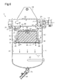
- FIG. 7 is a schematic diagram illustrating a collected liquid discharge system according to a second embodiment
- FIG. 8 is a schematic diagram illustrating a collected liquid discharge system according to a third embodiment
- FIG. 9 is a schematic diagram illustrating the structure of a collected liquid discharge system according to a modification.
- FIG. 10 is a schematic diagram illustrating the structure of a collected liquid discharge system according to a modification.
- a collected liquid discharge system is provided as part of a compressed air drying system, which dries compressed air delivered from a compressor.
- the compressed air drying system is mounted on a vehicle with an internal combustion engine.
- the compressed air drying system includes a compressor 1 , an air dryer 2 , and an oil separator 3 .
- the compressor 1 is coupled to the internal combustion engine of the vehicle.
- the compressed air delivered from the compressor 1 contains water and oil originating from, for example, lubricant.
- the water is contained in the compressed air primarily as water vapor, and oil is contained in the compressed air primarily as oil mist.
- the air dryer 2 contains a desiccant 4 and a filter (not shown) for trapping oil mist.
- the air dryer 2 includes an inlet 2 a and an outlet 2 b .
- the compressed air delivered from the compressor 1 flows in through the inlet 2 a .
- the compressed air from which water and oil have been removed, or compressed dried air flows out through the outlet 2 b .
- the compressed dried air that has flowed out through the outlet 2 b is stored in an air tank 5 .
- the compressed dried air stored in the air tank 5 is supplied to, for example, a brake system or an air suspension system.
- the air dryer 2 executes, besides a loading mode operation for trapping water and oil contained in compressed air, unloading mode operation, in which water and oil trapped by, for example, the desiccant 4 are expelled to the outside to regenerate the desiccant 4 .
- Fluid containing liquid, which includes water and oil, and air (purge air) to be discharged by execution of the unloading mode operation is discharged to the oil separator 3 through a liquid discharge port 2 c of the air dryer 2 .
- the oil separator 3 includes a liquid inlet port 3 a , which is connected to the liquid discharge port 2 c of the air dryer 2 , and an air discharge port 3 b .
- the oil separator 3 separates gas and liquid in the fluid that has flowed in through the liquid inlet port 3 a .
- the gas, which is the separated clean air, is expelled into the atmosphere through the air discharge port 3 b , and the collected liquid is stored in the interior of the oil separator 3 .
- a collected liquid discharge port 3 c for discharging collected liquid to the outside is provided in the bottom portion of the oil separator 3 .
- a collected liquid discharge hose 3 d is connected to the collected liquid discharge port 3 c .
- the collected liquid discharge hose 3 d is secured to a predetermined position such that the outlet of the collected liquid discharge hose 3 d is placed vertically upward from the collected liquid discharge port 3 c .
- the outlet of the collected liquid discharge hose 3 d is placed vertically downward from the collected liquid discharge port 3 c of the oil separator 3 .
- a liquid discharge passage 8 is connected to the liquid discharge port 2 c of the air dryer 2 .
- a directional control valve which is a three-way valve 10 in this embodiment, is connected to the outlet of the liquid discharge passage 8 .
- the three-way valve 10 corresponds to a mechanism for increasing the internal pressure of a reservoir, which is provided in the oil separator 3 and stores the collected liquid.
- the three-way valve 10 includes a first inlet 10 a , which is connected to the liquid discharge port 2 c of the air dryer 2 via the liquid discharge passage 8 , a second inlet 10 b , to which air is supplied from the outside, and an outlet 10 c , which is connected to the liquid inlet port 3 a of the oil separator 3 .
- the second inlet 10 b is connected to an air supply device 6 via an air supply passage 7 .
- the air supply device 6 is, for example, an air tank provided for discharging of the collected liquid.
- the outlet 10 c of the three-way valve 10 is connected to the liquid inlet port 3 a of the oil separator 3 via a conduit, which is a coupling passage 10 d in this embodiment.
- the oil separator 3 and the air supply device 6 configure a collected liquid discharge system 9 .
- the three-way valve 10 switches the direction of an L-shaped flow passage within the three-way valve 10 in accordance with the difference between the pressure at the first inlet 10 a and the pressure at the second inlet 10 b .
- the three-way valve 10 switches the communication state between a first mode, in which the first inlet 10 a communicates with the outlet 10 c , and a second mode, in which the second inlet 10 b communicates with the outlet 10 c .
- the first inlet 10 a does not communicate with the second inlet 10 b .
- the fluid flowing through the three-way valve 10 has an L flow pattern (see FIG. 1 ) from the first inlet 10 a toward the outlet 10 c
- the fluid flowing through the three-way valve 10 has an L flow pattern from the second inlet 10 b toward the outlet 10 c (see FIG. 2 ).
- the three-way valve 10 switches the flow direction such that the fluid flows from the first inlet 10 a toward the outlet 10 c . Accordingly, the fluid, which contains liquid, flows into the liquid inlet port 3 a of the oil separator 3 via the coupling passage 10 d.
- a supply valve (not shown) of the air supply device 6 is opened to supply air into the oil separator 3 via the air supply passage 7 .
- the three-way valve 10 switches the flow direction such that air flows from the second inlet 10 b toward the outlet 10 c . This increases the pressure of the air that has flowed into the oil separator 3 , thus pushing the collected liquid to be discharged from the collected liquid discharge port 3 c.
- the oil separator 3 includes a cylindrical case 11 having a closed end and a lid 12 , which seals the opening portion of the case 11 .
- the collected liquid discharge port 3 c described above is provided at the bottom portion of the case 11 .
- the lid 12 has the air discharge port 3 b , from which cleaned air is discharged.
- the air discharge port 3 b is connected to an air discharge hose 20 , which expels cleaned air into the atmosphere, via a discharge coupling member 19 .
- the lid 12 also has a mounting plate 29 , which secures the oil separator 3 to a receiving body.
- the lid 12 has the liquid inlet port 3 a described above in addition to the air discharge port 3 b .
- a hose for supplying air that has flowed out from the air dryer 2 is connected to the liquid inlet port 3 a via an introduction coupling member 18 .
- a disk-shaped cover 25 is provided between the case 11 and the lid 12 .
- the case 11 , the cover 25 , and the lid 12 are secured to one another by fastening bolts 27 in through-holes formed in a flange portion 26 of the case 11 , through-holes formed in the cover 25 , and threaded bores formed in the lid 12 .
- the space defined by the cover 25 and the lid 12 functions as a first expansion chamber 22 .
- a communication hole 28 is formed at the center portion of the cover 25 .
- a cylindrical accommodation member 30 having a lid is secured to the bottom surface of the cover 25 with bolts 27 .
- Flange portions 31 , 32 are respectively formed on the upper end and the lower end of the accommodation member 30 .
- the accommodation member 30 is fastened to the cover 25 by inserting the bolts 27 through the flange portion 31 .
- the space defined by the upper surface of the fastened accommodation member 30 and the cover 25 functions as a second expansion chamber 33 .
- the above-mentioned communication hole 28 which is formed in the cover 25 , connects the first expansion chamber 22 to the second expansion chamber 33 .
- Through-holes 35 are formed at the center portion of an upper wall 34 of the accommodation member 30 .
- the through-holes 35 and the communication hole 28 of the cover 25 are formed at positions that are not opposed to each other.
- Through-holes 36 are formed at the lower end of the side wall of the accommodation member 30 at intervals in the circumferential direction.
- the accommodation member 30 accommodates an oil trap 40 , which removes oil contained in purge air.
- the oil trap 40 collects oil by causing oil particles to strike the oil trap 40 .
- the oil trap 40 is made of a porous plastic sponge (urethane foam). Plates 43 with many through-holes are provided on the upper surface and the bottom surface of the sponge.
- a support disk 45 for supporting the oil trap 40 is secured to the flange portion 32 , which is formed at the lower end of the accommodation member 30 , with screws 46 .
- the support disk 45 has a diameter that is substantially equal to the inner diameter of the case 11 .
- the support disk 45 includes through-holes 47 for allowing, for example, liquid oil trapped by the oil trap 40 to drop.
- a reservoir which is a collected liquid storage portion 48 in this embodiment, is provided at the lower section of the case 11 and stores the collected liquid that has dropped through the through-holes 47 .
- a heater 49 for heating the stored liquid to vaporize water is provided in the collected liquid storage portion 48 . Heating of the heater 49 is controlled by using a non-illustrated thermostat.
- the purge air that has flowed in through the liquid inlet port 3 a strikes baffle plates 21 and is then introduced into the first expansion chamber 22 to be expanded.
- the purge air that has been expanded in the first expansion chamber 22 flows into the second expansion chamber 33 through the communication hole 28 , which is formed in the cover 25 , and is expanded in the second expansion chamber 33 .
- the expanded purge air flows into the oil trap 40 in the accommodation member 30 through the through-holes 35 in the upper wall 34 of the accommodation member 30 and passes through the interior of the oil trap 40 . This configuration removes oil particles and water contained in the purge air.
- the liquid water and oil trapped by the oil trap 40 moves through the oil trap 40 , reaches the upper surface of the support disk 45 , and drops through the through-holes 47 in the support disk 45 to be stored in the collected liquid storage portion 48 .
- the liquid moves along the same path as described above, passes through the oil trap 40 , and drops into the collected liquid storage portion 48 .
- the collected liquid stored in the collected liquid storage portion 48 is heated by the heater 49 so that the water is vaporized.
- the cleaned air, from which water and oil have been removed by the oil trap 40 flows through the through-holes 36 in the side surface of the accommodation member 30 into the space formed between the accommodation member 30 and the case 11 .
- the air that has passed through the space passes through a communication hole 50 formed in the cover 25 and a communication portion 23 in the lid 12 and is then discharged through the air discharge port 3 b.
- the collected liquid is discharged from the oil separator 3 with the operation of the compressor 1 being stopped by stopping the internal combustion engine of the vehicle.
- the collected liquid discharge hose 3 d which is connected to the oil separator 3 , is moved from the predetermined position to open the collected liquid discharge port 3 c as described above.
- the supply valve of the air supply device 6 is opened to supply air into the air supply passage 7 .
- the three-way valve 10 switches the internal flow direction such that air flows from the second inlet 10 b toward the outlet 10 c to supply air to the liquid inlet port 3 a of the oil separator 3 .
- the air supplied from the air supply device 6 passes through the liquid inlet port 3 a , the first expansion chamber 22 , the second expansion chamber 33 , and the oil trap 40 in the same manner as when the fluid, which contains liquid, is discharged from the air dryer 2 .
- Some of the air that has passed through the oil trap 40 passes through the space between the accommodation member 30 and the case 11 to be discharged from the air discharge port 3 b .
- the remaining part of the air that has passed through the oil trap 40 is introduced into the collected liquid storage portion 48 .
- the pressure in the collected liquid storage portion 48 is increased, and the pressure increase pushes out the collected liquid stored in the collected liquid storage portion 48 through the collected liquid discharge port 3 c . Consequently, compared to a case in which no air is supplied to the oil separator 3 , the flow rate of the collected liquid discharged from the collected liquid discharge port 3 c per unit time is increased, which allows the collected liquid to be discharged in a short time.
- the present embodiment has the following advantages.
- the three-way valve 10 which is connected to the air supply device 6 , causes the internal pressure of the collected liquid storage portion 48 to be increased when the collected liquid is discharged from the collected liquid storage portion 48 of the oil separator 3 .
- the pressure increase pushes the collected liquid toward the collected liquid discharge port 3 c .
- the liquid collected in the oil separator 3 is discharged in a short time.
- the three-way valve 10 switches the flow direction upstream of the oil separator 3 such that fluid flows from the liquid discharge port 2 c of the air dryer 2 toward the liquid inlet port 3 a of the oil separator 3 . Furthermore, when the collected liquid that is collected by the oil separator 3 is discharged, the three-way valve 10 switches the flow direction upstream of the oil separator 3 such that air flows from the air supply device 6 toward the oil separator 3 . Thus, the air delivered from the air supply device 6 increases the pressure in the oil separator 3 , pushing out the collected liquid stored in the oil separator 3 through the collected liquid discharge port 3 c . For this reason, the liquid collected in the oil separator 3 is discharged in a short time.
- FIG. 7 An oil separator and a collected liquid discharge system according to a second embodiment will now be described with reference to FIG. 7 .
- the description focuses on the difference between the first embodiment and the second embodiment.
- the structure of the oil separator differs from that of the first embodiment.
- the same reference numerals are given to those components that are substantially the same as the corresponding components of the first embodiment in the drawing, and overlapped explanations are omitted.
- the oil separator 3 includes an on-off valve 3 e located downstream of the air discharge port 3 b and, for example, in the middle of the air discharge hose 20 .
- the on-off valve 3 e stops expelling cleaned air from the air discharge port 3 b when the on-off valve 3 e is closed and discharges cleaned air from the air discharge port 3 b when the on-off valve 3 e is opened.
- the on-off valve 3 e is closed when the liquid collected by the oil separator 3 is started to be discharged.
- the collected liquid discharge hose 3 d which is connected to the oil separator 3 , is moved from the predetermined position to open the collected liquid discharge port 3 c as described above. Furthermore, the on-off valve 3 e of the oil separator 3 is closed, and the supply valve of the air supply device 6 is opened to supply air to the air supply passage 7 .
- the flow direction of the three-way valve 10 is switched such that air flows from the second inlet 10 b toward the outlet 10 c.
- the air that has flowed into the oil separator 3 via the three-way valve 10 passes through the oil trap 40 and is introduced to the collected liquid storage portion 48 without being discharged from the air discharge port 3 b .
- the collected liquid stored in the collected liquid storage portion 48 is pushed with a great pressure, and the collected liquid is discharged in a short time.
- the present embodiment has the following advantage as well as the advantages (1) to (2).
- FIG. 8 An oil separator and a collected liquid discharge system according to a third embodiment will now be described with reference to FIG. 8 .
- the description focuses on the difference between the first embodiment and the third embodiment.
- the structure of the gas supply source differs from that of the first embodiment.
- the same reference numerals are given to those components that are substantially the same as the corresponding components of the first embodiment in the drawing, and overlapped explanations are omitted.
- the second inlet 10 b of the three-way valve 10 is connected to the downstream end of the air tank 5 , which stores the compressed dried air that flows out of the air dryer 2 , via the air supply passage 7 .
- a flow rate regulating valve 7 a which regulates the flow rate of the compressed dried air supplied from the air tank 5 to the oil separator 3 , is located in the middle of the air supply passage 7 .
- a dried air supply passage 5 b extends from the air tank 5 to be connected to various systems.
- An on-off valve 5 a for selectively opening and closing a dried air supply passage 5 b is located in the dried air supply passage 5 b . This configuration eliminates the need for using an external air supply source and utilizes the air tank 5 , which is provided in the compressed air drying system.
- the collected liquid discharge hose 3 d which is connected to the oil separator 3 , is moved from the predetermined position to open the collected liquid discharge port 3 c as described above. Furthermore, the on-off valve 5 a located downstream of the air tank 5 is closed, and the flow rate regulating valve 7 a is opened to supply air to the air supply passage 7 .
- Some of the compressed dried air supplied from the air tank 5 passes through the oil trap 40 and is then discharged from the air discharge port 3 b , and the remaining part of the compressed dried air is introduced into the collected liquid storage portion 48 .
- Increase in the pressure in the collected liquid storage portion 48 causes the collected liquid to be pushed out through the collected liquid discharge port 3 c.
- the present embodiment has the following advantage as well as the advantages (1) to (2).
- the air supply passage 7 which is connected to the three-way valve 10 , is connected to the air tank 5 , which stores the compressed dried air that flowed out of the air dryer 2 .
- This configuration eliminates the need for providing a dedicated air tank and utilizes the existing air tank 5 .
- the oil separator 3 may have other structures as long as the liquid inlet port 3 a , the oil trap 40 , the air discharge port 3 b , and the collected liquid discharge port 3 c are provided.
- the oil trap 40 may be made of, for example, finely porous metal material (such as a crushed aluminum member) or baffle plates.
- the collected liquid discharge hose 3 d is connected to the collected liquid discharge port 3 c of the oil separator 3 .
- the collected liquid discharge hose 3 d may be omitted, and a plug may be provided in the collected liquid discharge port 3 c to directly discharge the collected liquid from the collected liquid discharge port 3 c.
- the number of the heater 49 may be changed as required, and the heater 49 may also be omitted.
- the oil separator 3 may be a cartridge in which the accommodation member 30 is secured to the main body including the case 11 with a threaded portion.
- the cover 25 may also be omitted.
- the structure for connecting the liquid inlet port 3 a to the hose of the air dryer and the structure for connecting the air discharge port 3 b to the air discharge hose 20 may be other known connecting structures.
- a through-hole for discharging air may be formed in the bottom wall of the accommodation member 30 .
- the outlet 10 c of the three-way valve 10 is connected to the liquid inlet port 3 a of the oil separator 3 , but may be connected to the air discharge port 3 b .
- air is supplied from the air supply device 6 or the air tank 5 to increase the pressure in the oil separator 3 .
- the on-off valve 3 e is located on the side of the liquid inlet port 3 a.
- the air supply device 6 or the air tank 5 is connected to the oil separator 3 via the three-way valve 10 .
- a gas supply source that supplies gas other than air such as nitrogen may be connected to the oil separator 3 .
- the directional control valve is a three-way valve, but may be any valves that are capable of switching the flow direction.
- an electromagnetic valve which switches the flow direction by selectively energizing and de-energizing the valve
- a hydraulic valve which switches the flow direction by hydraulic pressure
- the oil separator 3 is provided in the exhaust system of the air dryer 2 , which is downstream of the compressor 1 of the air system.
- the oil separator 3 may be located downstream of the compressor 1 of the air system and upstream of the air dryer 2 .
- oil is separated from the air containing, for example, lubricant in the compressor 1 , and cleaned air is supplied to the air dryer 2 .
- the desiccant in the air dryer 2 is prevented from being deteriorated due to the oil.
- a collected liquid reservoir tank 60 may be connected to the collected liquid discharge port 3 c of the oil separator 3 via the collected liquid discharge hose 3 d .
- the collected liquid reservoir tank 60 stores the collected liquid discharged from the oil separator 3 .
- the collected liquid is drained from the oil separator by gravity into the collected liquid reservoir tank 60 .
- the collected liquid stored in the collected liquid storage portion 48 of the oil separator 3 is discharged by increasing the pressure in the collected liquid storage portion 48 by supplying air from the air supply device 6 .
- an introduction port 61 of the collected liquid reservoir tank 60 (or the liquid surface of the collected liquid reservoir tank 60 ) may be located higher than the collected liquid discharge port 3 c of the oil separator 3 in the vertical direction.
- the compressed air drying system may include an oil mist separator 70 in addition to the air dryer 2 and the oil separator 3 .
- the oil mist separator 70 includes a filter for trapping oil mist and differs from the air dryer 2 in that it does not have a desiccant.
- the oil mist separator 70 is located between the compressor 1 and the air dryer 2 .
- the oil mist separator 70 has an inlet 70 a , which is connected to the compressor 1 , and an outlet 70 b , which is connected to the inlet 2 a of the air dryer 2 .
- the outlet 70 b discharges air from which oil mist has been removed.
- the oil mist separator 70 further includes a liquid discharge valve.
- the compressed air is discharged from a liquid discharge port 70 c together with the oil trapped by the filter.
- a hose 71 and a branch pipe 72 are connected to the liquid discharge port 70 c of the oil mist separator 70 .
- a coupling pipe 74 is connected to the liquid discharge port 2 c of the air dryer 2 via a hose 73 .
- the branch pipe 72 is connected to the first inlet 10 a of the three-way valve 10 with a hose 75 .
- the oil separator 3 may include an air introduction port, which introduces air into the oil separator 3 to increase the internal pressure of the collected liquid storage portion 48 .
- the air introduction port is connected to an air supply source other than the air supply device 6 .
- the air supply source may be the air tank 5 .
- a flow rate regulating valve may be provided between the air introduction port and the air supply source to regulate the amount of air supplied to the oil separator 3 .
- the air introduction port and the three-way valve 10 correspond to a mechanism that increases the internal pressure of the reservoir, which is provided in the oil separator 3 and stores the collected liquid.
- the compressor 1 is not necessarily coupled to the internal combustion engine, but may have a separate motive power source.
- the compressed air drying system is mounted on a vehicle with an internal combustion engine, but may be mounted on a vehicle with a driving source other than the internal combustion engine. Furthermore, the compressed air drying system may be mounted on machines other than vehicles.
- Discharge Coupling Member 20 . . . Air Discharge Hose, 21 . . . Baffle Plate, 22 . . . First Expansion Chamber, 23 . . . Communication Portion, 25 . . . Cover, 26 . . . Flange, 27 . . . Bolt, 28 . . . Communication Hole, 29 . . . Mounting Plate, 30 . . . Accommodation Member, 31 . . . Flange, 32 . . . Flange, 33 . . . Second Expansion Chamber, 34 . . . Upper Wall, 35 . . . Through-hole, 36 . . . Through-hole, 40 . . .
- Oil Trap 41 . . . Impingement Member, 45 . . . Support Disk, 46 . . . Screw, 47 . . . Through-hole, 48 . . . Collected liquid Storage Portion, 49 . . . Heater, 50 . . . Communication Hole.
Landscapes
- Engineering & Computer Science (AREA)
- Chemical & Material Sciences (AREA)
- Mechanical Engineering (AREA)
- Chemical Kinetics & Catalysis (AREA)
- General Engineering & Computer Science (AREA)
- General Chemical & Material Sciences (AREA)
- Oil, Petroleum & Natural Gas (AREA)
- Analytical Chemistry (AREA)
- Transportation (AREA)
- Separating Particles In Gases By Inertia (AREA)
- Compressor (AREA)
- Filtering Of Dispersed Particles In Gases (AREA)
- Drying Of Gases (AREA)
Applications Claiming Priority (3)
| Application Number | Priority Date | Filing Date | Title |
|---|---|---|---|
| JP2014036755 | 2014-02-27 | ||
| JP2014-036755 | 2014-02-27 | ||
| PCT/JP2015/055853 WO2015129856A1 (ja) | 2014-02-27 | 2015-02-27 | オイルセパレータ及びドレン排出システム |
Publications (2)
| Publication Number | Publication Date |
|---|---|
| US20170007944A1 US20170007944A1 (en) | 2017-01-12 |
| US10099159B2 true US10099159B2 (en) | 2018-10-16 |
Family
ID=54009169
Family Applications (1)
| Application Number | Title | Priority Date | Filing Date |
|---|---|---|---|
| US15/121,202 Active 2035-05-01 US10099159B2 (en) | 2014-02-27 | 2015-02-27 | Oil separator and drain discharge system |
Country Status (5)
| Country | Link |
|---|---|
| US (1) | US10099159B2 (ja) |
| JP (1) | JP6622184B2 (ja) |
| CN (1) | CN106457104B (ja) |
| DE (1) | DE112015001013T5 (ja) |
| WO (1) | WO2015129856A1 (ja) |
Families Citing this family (6)
| Publication number | Priority date | Publication date | Assignee | Title |
|---|---|---|---|---|
| WO2016031985A1 (ja) * | 2014-08-29 | 2016-03-03 | ナブテスコオートモーティブ 株式会社 | オイルセパレータ及び圧縮空気乾燥システム |
| US10807582B2 (en) * | 2018-03-27 | 2020-10-20 | Bendix Commercial Vehicle Systems Llc | Effluent processing apparatus and method for a vehicle air brake charging system |
| EP3650107A1 (en) * | 2018-11-08 | 2020-05-13 | KNORR-BREMSE Systeme für Nutzfahrzeuge GmbH | Purge gas contaminate elimination system for a vehicle |
| DE102019108154B4 (de) * | 2019-03-29 | 2023-04-20 | Voith Patent Gmbh | Vorrichtung zum Verschließen des Arbeitsraumentlüftungskanals eines Retarders |
| JP2021090902A (ja) * | 2019-12-09 | 2021-06-17 | 日野自動車株式会社 | オイルセパレータ及び油水排出方法 |
| CN115076069B (zh) * | 2022-07-01 | 2023-12-01 | 常州市东南电器电机有限公司 | 一种具有防水功能的真空泵 |
Citations (12)
| Publication number | Priority date | Publication date | Assignee | Title |
|---|---|---|---|---|
| US4234327A (en) * | 1979-06-04 | 1980-11-18 | Wills Bill R | Compressed air system having an air dryer |
| JPS579320U (ja) | 1980-06-16 | 1982-01-18 | ||
| JPS63103718U (ja) | 1986-12-22 | 1988-07-05 | ||
| JP2000126538A (ja) | 1998-10-23 | 2000-05-09 | American Standard Inc | 掃引空気として失われる空気を減少させる機構を備えた膜型空気ドライヤおよびその膜型空気ドライヤ用の制御システム |
| JP2008173544A (ja) | 2007-01-17 | 2008-07-31 | Anest Iwata Corp | 負圧形成装置及びそのドレン排出方法 |
| WO2013168758A1 (ja) | 2012-05-10 | 2013-11-14 | ナブテスコオートモーティブ 株式会社 | オイルセパレータ |
| JP2013234632A (ja) | 2012-05-10 | 2013-11-21 | Nabtesco Automotive Corp | オイルセパレータ |
| US20150033685A1 (en) | 2012-02-27 | 2015-02-05 | Nabtesco Automotive Corporation | Oil separator |
| US20150040767A1 (en) | 2012-02-27 | 2015-02-12 | Nabtesco Automotive Corporation | Oil separator |
| US20150052861A1 (en) | 2012-02-27 | 2015-02-26 | Nabtesco Automotive Corporation | Oil separator |
| US20150152763A1 (en) * | 2012-05-09 | 2015-06-04 | Nabtesco Automotive Corporation | Oil separator |
| US20150343356A1 (en) | 2012-07-02 | 2015-12-03 | Nabtesco Automotive Corporation | Oil separator |
Family Cites Families (4)
| Publication number | Priority date | Publication date | Assignee | Title |
|---|---|---|---|---|
| JPH0710478U (ja) * | 1993-07-23 | 1995-02-14 | 三輪精機株式会社 | 車両用圧縮空気系路の油排出装置 |
| US20080152519A1 (en) * | 2006-12-20 | 2008-06-26 | Mei-Lien Chern | Gas-oil separator with an oil type air compressor |
| CN202569821U (zh) * | 2012-05-18 | 2012-12-05 | 北京三聚环保新材料股份有限公司 | 一种自动排液的聚结分离器 |
| CN103575472B (zh) * | 2012-07-23 | 2016-12-21 | 中国石油化工股份有限公司 | 漏液检测和过滤装置 |
-
2015
- 2015-02-27 US US15/121,202 patent/US10099159B2/en active Active
- 2015-02-27 WO PCT/JP2015/055853 patent/WO2015129856A1/ja active Application Filing
- 2015-02-27 JP JP2016505320A patent/JP6622184B2/ja active Active
- 2015-02-27 CN CN201580010196.5A patent/CN106457104B/zh active Active
- 2015-02-27 DE DE112015001013.0T patent/DE112015001013T5/de active Pending
Patent Citations (14)
| Publication number | Priority date | Publication date | Assignee | Title |
|---|---|---|---|---|
| US4234327A (en) * | 1979-06-04 | 1980-11-18 | Wills Bill R | Compressed air system having an air dryer |
| JPS579320U (ja) | 1980-06-16 | 1982-01-18 | ||
| JPS63103718U (ja) | 1986-12-22 | 1988-07-05 | ||
| JP2000126538A (ja) | 1998-10-23 | 2000-05-09 | American Standard Inc | 掃引空気として失われる空気を減少させる機構を備えた膜型空気ドライヤおよびその膜型空気ドライヤ用の制御システム |
| US6070339A (en) | 1998-10-23 | 2000-06-06 | Westinghouse Air Brake Company | Membrane air dryer with scheme to reduce air lost as sweep air |
| JP2008173544A (ja) | 2007-01-17 | 2008-07-31 | Anest Iwata Corp | 負圧形成装置及びそのドレン排出方法 |
| US20150040767A1 (en) | 2012-02-27 | 2015-02-12 | Nabtesco Automotive Corporation | Oil separator |
| US20150033685A1 (en) | 2012-02-27 | 2015-02-05 | Nabtesco Automotive Corporation | Oil separator |
| US20150052861A1 (en) | 2012-02-27 | 2015-02-26 | Nabtesco Automotive Corporation | Oil separator |
| US20150152763A1 (en) * | 2012-05-09 | 2015-06-04 | Nabtesco Automotive Corporation | Oil separator |
| JP2013234632A (ja) | 2012-05-10 | 2013-11-21 | Nabtesco Automotive Corp | オイルセパレータ |
| WO2013168758A1 (ja) | 2012-05-10 | 2013-11-14 | ナブテスコオートモーティブ 株式会社 | オイルセパレータ |
| US20150135961A1 (en) | 2012-05-10 | 2015-05-21 | Nabtesco Automotive Corporation | Oil separator |
| US20150343356A1 (en) | 2012-07-02 | 2015-12-03 | Nabtesco Automotive Corporation | Oil separator |
Non-Patent Citations (2)
| Title |
|---|
| International Preliminary Report on Patentability and the Written Opinion of the International Searching Authority as issued in International Patent Application No. PCT/JP2015/055853, dated Aug. 30, 2016. |
| International Search Report as issued in International Patent Application No. PCT/JP2015/055853, dated Apr. 7, 2015. |
Also Published As
| Publication number | Publication date |
|---|---|
| US20170007944A1 (en) | 2017-01-12 |
| JPWO2015129856A1 (ja) | 2017-03-30 |
| WO2015129856A1 (ja) | 2015-09-03 |
| CN106457104A (zh) | 2017-02-22 |
| JP6622184B2 (ja) | 2019-12-18 |
| DE112015001013T5 (de) | 2016-11-24 |
| CN106457104B (zh) | 2019-07-05 |
Similar Documents
| Publication | Publication Date | Title |
|---|---|---|
| US10099159B2 (en) | Oil separator and drain discharge system | |
| JP6652587B2 (ja) | 圧縮空気供給システム | |
| JP6373757B2 (ja) | 圧縮空気乾燥装置 | |
| US10082057B2 (en) | Oil separator | |
| US9533246B2 (en) | Oil separator | |
| US10173660B2 (en) | Oil separator | |
| US10603619B2 (en) | Oil separator | |
| JP6576911B2 (ja) | 圧縮空気乾燥システム及び圧縮空気乾燥システムの再生方法 | |
| EP3150271B1 (en) | Compressed-air drying system | |
| WO2007074725A1 (ja) | アキュームレータ | |
| US10130910B2 (en) | Compressed air drying device | |
| US10343108B2 (en) | Air drier | |
| WO2015182584A1 (ja) | オイルセパレータ及び車両用油分分離システム | |
| JP2021137808A (ja) | オイルセパレータ | |
| JP2013032733A (ja) | エアドライヤ装置用キャッチタンク装置 | |
| JP7253839B1 (ja) | 圧縮空気圧回路構造 | |
| JP2016215127A (ja) | オイルセパレータ | |
| JP2014008471A (ja) | オイルセパレータ |
Legal Events
| Date | Code | Title | Description |
|---|---|---|---|
| AS | Assignment |
Owner name: NABTESCO AUTOMOTIVE CORPORATION, JAPAN Free format text: ASSIGNMENT OF ASSIGNORS INTEREST;ASSIGNORS:SUGIO, TAKUYA;KAWANAMI, HIROAKI;SIGNING DATES FROM 20160923 TO 20160926;REEL/FRAME:040433/0720 |
|
| STCF | Information on status: patent grant |
Free format text: PATENTED CASE |
|
| MAFP | Maintenance fee payment |
Free format text: PAYMENT OF MAINTENANCE FEE, 4TH YEAR, LARGE ENTITY (ORIGINAL EVENT CODE: M1551); ENTITY STATUS OF PATENT OWNER: LARGE ENTITY Year of fee payment: 4 |