RU2693503C1 - Electrophotographic image forming device, developing device and coupling element - Google Patents
Electrophotographic image forming device, developing device and coupling element Download PDFInfo
- Publication number
- RU2693503C1 RU2693503C1 RU2018129750A RU2018129750A RU2693503C1 RU 2693503 C1 RU2693503 C1 RU 2693503C1 RU 2018129750 A RU2018129750 A RU 2018129750A RU 2018129750 A RU2018129750 A RU 2018129750A RU 2693503 C1 RU2693503 C1 RU 2693503C1
- Authority
- RU
- Russia
- Prior art keywords
- axis
- developing cartridge
- coupling
- coupling element
- developing
- Prior art date
Links
- 230000008878 coupling Effects 0.000 title claims abstract description 1046
- 238000010168 coupling process Methods 0.000 title claims abstract description 1046
- 238000005859 coupling reaction Methods 0.000 title claims abstract description 1046
- 238000011161 development Methods 0.000 claims abstract description 181
- 230000005540 biological transmission Effects 0.000 claims abstract description 146
- 238000012546 transfer Methods 0.000 claims description 74
- 239000000463 material Substances 0.000 claims description 58
- 230000033001 locomotion Effects 0.000 claims description 41
- 238000003825 pressing Methods 0.000 claims description 26
- 238000013461 design Methods 0.000 claims description 22
- 239000007769 metal material Substances 0.000 claims description 17
- 238000000034 method Methods 0.000 claims description 16
- 229930182556 Polyacetal Natural products 0.000 claims description 11
- 229920006324 polyoxymethylene Polymers 0.000 claims description 11
- 230000008569 process Effects 0.000 claims description 7
- 239000002861 polymer material Substances 0.000 claims description 4
- 238000006073 displacement reaction Methods 0.000 claims description 2
- 230000007246 mechanism Effects 0.000 abstract description 15
- 239000000126 substance Substances 0.000 abstract 1
- 238000009434 installation Methods 0.000 description 23
- 238000003384 imaging method Methods 0.000 description 21
- 230000000903 blocking effect Effects 0.000 description 15
- 230000006870 function Effects 0.000 description 15
- 230000004044 response Effects 0.000 description 15
- 230000015572 biosynthetic process Effects 0.000 description 13
- 230000002829 reductive effect Effects 0.000 description 12
- 230000002093 peripheral effect Effects 0.000 description 9
- 229920001971 elastomer Polymers 0.000 description 8
- 239000013013 elastic material Substances 0.000 description 7
- 239000005060 rubber Substances 0.000 description 7
- 238000003780 insertion Methods 0.000 description 6
- 230000037431 insertion Effects 0.000 description 6
- 238000003754 machining Methods 0.000 description 6
- 238000009987 spinning Methods 0.000 description 6
- 239000002184 metal Substances 0.000 description 5
- 229910052751 metal Inorganic materials 0.000 description 5
- 238000011144 upstream manufacturing Methods 0.000 description 5
- 238000013459 approach Methods 0.000 description 4
- 239000003086 colorant Substances 0.000 description 4
- 238000010276 construction Methods 0.000 description 4
- 230000009467 reduction Effects 0.000 description 4
- 230000008859 change Effects 0.000 description 3
- 238000004140 cleaning Methods 0.000 description 3
- 230000006835 compression Effects 0.000 description 3
- 238000007906 compression Methods 0.000 description 3
- 230000000670 limiting effect Effects 0.000 description 3
- 238000012423 maintenance Methods 0.000 description 3
- 238000004519 manufacturing process Methods 0.000 description 3
- XEEYBQQBJWHFJM-UHFFFAOYSA-N Iron Chemical compound [Fe] XEEYBQQBJWHFJM-UHFFFAOYSA-N 0.000 description 2
- 235000008331 Pinus X rigitaeda Nutrition 0.000 description 2
- 235000011613 Pinus brutia Nutrition 0.000 description 2
- 241000018646 Pinus brutia Species 0.000 description 2
- 230000009471 action Effects 0.000 description 2
- 230000007423 decrease Effects 0.000 description 2
- 238000010586 diagram Methods 0.000 description 2
- 239000006260 foam Substances 0.000 description 2
- 230000006872 improvement Effects 0.000 description 2
- 238000001746 injection moulding Methods 0.000 description 2
- 230000002452 interceptive effect Effects 0.000 description 2
- 230000003287 optical effect Effects 0.000 description 2
- 230000003071 parasitic effect Effects 0.000 description 2
- 230000036961 partial effect Effects 0.000 description 2
- 229920000642 polymer Polymers 0.000 description 2
- 238000012545 processing Methods 0.000 description 2
- 230000000087 stabilizing effect Effects 0.000 description 2
- 230000003313 weakening effect Effects 0.000 description 2
- 238000003466 welding Methods 0.000 description 2
- 241000208202 Linaceae Species 0.000 description 1
- 235000004431 Linum usitatissimum Nutrition 0.000 description 1
- 230000004308 accommodation Effects 0.000 description 1
- 230000000712 assembly Effects 0.000 description 1
- 238000000429 assembly Methods 0.000 description 1
- 238000005452 bending Methods 0.000 description 1
- 230000008901 benefit Effects 0.000 description 1
- 239000004020 conductor Substances 0.000 description 1
- 239000000470 constituent Substances 0.000 description 1
- 230000001276 controlling effect Effects 0.000 description 1
- 239000000806 elastomer Substances 0.000 description 1
- 230000008014 freezing Effects 0.000 description 1
- 238000007710 freezing Methods 0.000 description 1
- 239000003365 glass fiber Substances 0.000 description 1
- 238000010438 heat treatment Methods 0.000 description 1
- 229910052742 iron Inorganic materials 0.000 description 1
- 238000012986 modification Methods 0.000 description 1
- 230000004048 modification Effects 0.000 description 1
- 238000000465 moulding Methods 0.000 description 1
- 239000004033 plastic Substances 0.000 description 1
- 239000004417 polycarbonate Substances 0.000 description 1
- 229920000515 polycarbonate Polymers 0.000 description 1
- 230000001105 regulatory effect Effects 0.000 description 1
- 230000008439 repair process Effects 0.000 description 1
- 238000005096 rolling process Methods 0.000 description 1
- 238000004381 surface treatment Methods 0.000 description 1
Images


Classifications
-
- G—PHYSICS
- G03—PHOTOGRAPHY; CINEMATOGRAPHY; ANALOGOUS TECHNIQUES USING WAVES OTHER THAN OPTICAL WAVES; ELECTROGRAPHY; HOLOGRAPHY
- G03G—ELECTROGRAPHY; ELECTROPHOTOGRAPHY; MAGNETOGRAPHY
- G03G15/00—Apparatus for electrographic processes using a charge pattern
- G03G15/06—Apparatus for electrographic processes using a charge pattern for developing
-
- G—PHYSICS
- G03—PHOTOGRAPHY; CINEMATOGRAPHY; ANALOGOUS TECHNIQUES USING WAVES OTHER THAN OPTICAL WAVES; ELECTROGRAPHY; HOLOGRAPHY
- G03G—ELECTROGRAPHY; ELECTROPHOTOGRAPHY; MAGNETOGRAPHY
- G03G21/00—Arrangements not provided for by groups G03G13/00 - G03G19/00, e.g. cleaning, elimination of residual charge
- G03G21/16—Mechanical means for facilitating the maintenance of the apparatus, e.g. modular arrangements
- G03G21/18—Mechanical means for facilitating the maintenance of the apparatus, e.g. modular arrangements using a processing cartridge, whereby the process cartridge comprises at least two image processing means in a single unit
- G03G21/1839—Means for handling the process cartridge in the apparatus body
- G03G21/1857—Means for handling the process cartridge in the apparatus body for transmitting mechanical drive power to the process cartridge, drive mechanisms, gears, couplings, braking mechanisms
- G03G21/186—Axial couplings
-
- G—PHYSICS
- G03—PHOTOGRAPHY; CINEMATOGRAPHY; ANALOGOUS TECHNIQUES USING WAVES OTHER THAN OPTICAL WAVES; ELECTROGRAPHY; HOLOGRAPHY
- G03G—ELECTROGRAPHY; ELECTROPHOTOGRAPHY; MAGNETOGRAPHY
- G03G21/00—Arrangements not provided for by groups G03G13/00 - G03G19/00, e.g. cleaning, elimination of residual charge
- G03G21/16—Mechanical means for facilitating the maintenance of the apparatus, e.g. modular arrangements
-
- F—MECHANICAL ENGINEERING; LIGHTING; HEATING; WEAPONS; BLASTING
- F16—ENGINEERING ELEMENTS AND UNITS; GENERAL MEASURES FOR PRODUCING AND MAINTAINING EFFECTIVE FUNCTIONING OF MACHINES OR INSTALLATIONS; THERMAL INSULATION IN GENERAL
- F16D—COUPLINGS FOR TRANSMITTING ROTATION; CLUTCHES; BRAKES
- F16D1/00—Couplings for rigidly connecting two coaxial shafts or other movable machine elements
- F16D1/10—Quick-acting couplings in which the parts are connected by simply bringing them together axially
- F16D1/101—Quick-acting couplings in which the parts are connected by simply bringing them together axially without axial retaining means rotating with the coupling
-
- F—MECHANICAL ENGINEERING; LIGHTING; HEATING; WEAPONS; BLASTING
- F16—ENGINEERING ELEMENTS AND UNITS; GENERAL MEASURES FOR PRODUCING AND MAINTAINING EFFECTIVE FUNCTIONING OF MACHINES OR INSTALLATIONS; THERMAL INSULATION IN GENERAL
- F16D—COUPLINGS FOR TRANSMITTING ROTATION; CLUTCHES; BRAKES
- F16D3/00—Yielding couplings, i.e. with means permitting movement between the connected parts during the drive
- F16D3/02—Yielding couplings, i.e. with means permitting movement between the connected parts during the drive adapted to specific functions
- F16D3/04—Yielding couplings, i.e. with means permitting movement between the connected parts during the drive adapted to specific functions specially adapted to allow radial displacement, e.g. Oldham couplings
-
- G—PHYSICS
- G03—PHOTOGRAPHY; CINEMATOGRAPHY; ANALOGOUS TECHNIQUES USING WAVES OTHER THAN OPTICAL WAVES; ELECTROGRAPHY; HOLOGRAPHY
- G03G—ELECTROGRAPHY; ELECTROPHOTOGRAPHY; MAGNETOGRAPHY
- G03G15/00—Apparatus for electrographic processes using a charge pattern
- G03G15/01—Apparatus for electrographic processes using a charge pattern for producing multicoloured copies
- G03G15/0105—Details of unit
- G03G15/0121—Details of unit for developing
-
- G—PHYSICS
- G03—PHOTOGRAPHY; CINEMATOGRAPHY; ANALOGOUS TECHNIQUES USING WAVES OTHER THAN OPTICAL WAVES; ELECTROGRAPHY; HOLOGRAPHY
- G03G—ELECTROGRAPHY; ELECTROPHOTOGRAPHY; MAGNETOGRAPHY
- G03G15/00—Apparatus for electrographic processes using a charge pattern
- G03G15/01—Apparatus for electrographic processes using a charge pattern for producing multicoloured copies
- G03G15/0142—Structure of complete machines
- G03G15/0147—Structure of complete machines using a single reusable electrographic recording member
- G03G15/0152—Structure of complete machines using a single reusable electrographic recording member onto which the monocolour toner images are superposed before common transfer from the recording member
- G03G15/0173—Structure of complete machines using a single reusable electrographic recording member onto which the monocolour toner images are superposed before common transfer from the recording member plural rotations of recording member to produce multicoloured copy, e.g. rotating set of developing units
-
- G—PHYSICS
- G03—PHOTOGRAPHY; CINEMATOGRAPHY; ANALOGOUS TECHNIQUES USING WAVES OTHER THAN OPTICAL WAVES; ELECTROGRAPHY; HOLOGRAPHY
- G03G—ELECTROGRAPHY; ELECTROPHOTOGRAPHY; MAGNETOGRAPHY
- G03G15/00—Apparatus for electrographic processes using a charge pattern
- G03G15/06—Apparatus for electrographic processes using a charge pattern for developing
- G03G15/08—Apparatus for electrographic processes using a charge pattern for developing using a solid developer, e.g. powder developer
- G03G15/0806—Apparatus for electrographic processes using a charge pattern for developing using a solid developer, e.g. powder developer on a donor element, e.g. belt, roller
- G03G15/081—Apparatus for electrographic processes using a charge pattern for developing using a solid developer, e.g. powder developer on a donor element, e.g. belt, roller characterised by the developer handling means after the supply and before the regulating, e.g. means for preventing developer blocking
-
- G—PHYSICS
- G03—PHOTOGRAPHY; CINEMATOGRAPHY; ANALOGOUS TECHNIQUES USING WAVES OTHER THAN OPTICAL WAVES; ELECTROGRAPHY; HOLOGRAPHY
- G03G—ELECTROGRAPHY; ELECTROPHOTOGRAPHY; MAGNETOGRAPHY
- G03G15/00—Apparatus for electrographic processes using a charge pattern
- G03G15/06—Apparatus for electrographic processes using a charge pattern for developing
- G03G15/08—Apparatus for electrographic processes using a charge pattern for developing using a solid developer, e.g. powder developer
- G03G15/0806—Apparatus for electrographic processes using a charge pattern for developing using a solid developer, e.g. powder developer on a donor element, e.g. belt, roller
- G03G15/0815—Apparatus for electrographic processes using a charge pattern for developing using a solid developer, e.g. powder developer on a donor element, e.g. belt, roller characterised by the developer handling means after the developing zone and before the supply, e.g. developer recovering roller
-
- G—PHYSICS
- G03—PHOTOGRAPHY; CINEMATOGRAPHY; ANALOGOUS TECHNIQUES USING WAVES OTHER THAN OPTICAL WAVES; ELECTROGRAPHY; HOLOGRAPHY
- G03G—ELECTROGRAPHY; ELECTROPHOTOGRAPHY; MAGNETOGRAPHY
- G03G15/00—Apparatus for electrographic processes using a charge pattern
- G03G15/06—Apparatus for electrographic processes using a charge pattern for developing
- G03G15/08—Apparatus for electrographic processes using a charge pattern for developing using a solid developer, e.g. powder developer
- G03G15/0822—Arrangements for preparing, mixing, supplying or dispensing developer
- G03G15/0865—Arrangements for supplying new developer
-
- G—PHYSICS
- G03—PHOTOGRAPHY; CINEMATOGRAPHY; ANALOGOUS TECHNIQUES USING WAVES OTHER THAN OPTICAL WAVES; ELECTROGRAPHY; HOLOGRAPHY
- G03G—ELECTROGRAPHY; ELECTROPHOTOGRAPHY; MAGNETOGRAPHY
- G03G15/00—Apparatus for electrographic processes using a charge pattern
- G03G15/06—Apparatus for electrographic processes using a charge pattern for developing
- G03G15/08—Apparatus for electrographic processes using a charge pattern for developing using a solid developer, e.g. powder developer
- G03G15/0896—Arrangements or disposition of the complete developer unit or parts thereof not provided for by groups G03G15/08 - G03G15/0894
-
- G—PHYSICS
- G03—PHOTOGRAPHY; CINEMATOGRAPHY; ANALOGOUS TECHNIQUES USING WAVES OTHER THAN OPTICAL WAVES; ELECTROGRAPHY; HOLOGRAPHY
- G03G—ELECTROGRAPHY; ELECTROPHOTOGRAPHY; MAGNETOGRAPHY
- G03G21/00—Arrangements not provided for by groups G03G13/00 - G03G19/00, e.g. cleaning, elimination of residual charge
- G03G21/16—Mechanical means for facilitating the maintenance of the apparatus, e.g. modular arrangements
- G03G21/1642—Mechanical means for facilitating the maintenance of the apparatus, e.g. modular arrangements for connecting the different parts of the apparatus
- G03G21/1647—Mechanical connection means
-
- G—PHYSICS
- G03—PHOTOGRAPHY; CINEMATOGRAPHY; ANALOGOUS TECHNIQUES USING WAVES OTHER THAN OPTICAL WAVES; ELECTROGRAPHY; HOLOGRAPHY
- G03G—ELECTROGRAPHY; ELECTROPHOTOGRAPHY; MAGNETOGRAPHY
- G03G21/00—Arrangements not provided for by groups G03G13/00 - G03G19/00, e.g. cleaning, elimination of residual charge
- G03G21/16—Mechanical means for facilitating the maintenance of the apparatus, e.g. modular arrangements
- G03G21/1661—Mechanical means for facilitating the maintenance of the apparatus, e.g. modular arrangements means for handling parts of the apparatus in the apparatus
- G03G21/1676—Mechanical means for facilitating the maintenance of the apparatus, e.g. modular arrangements means for handling parts of the apparatus in the apparatus for the developer unit
-
- G—PHYSICS
- G03—PHOTOGRAPHY; CINEMATOGRAPHY; ANALOGOUS TECHNIQUES USING WAVES OTHER THAN OPTICAL WAVES; ELECTROGRAPHY; HOLOGRAPHY
- G03G—ELECTROGRAPHY; ELECTROPHOTOGRAPHY; MAGNETOGRAPHY
- G03G2215/00—Apparatus for electrophotographic processes
- G03G2215/01—Apparatus for electrophotographic processes for producing multicoloured copies
- G03G2215/0167—Apparatus for electrophotographic processes for producing multicoloured copies single electrographic recording member
- G03G2215/0174—Apparatus for electrophotographic processes for producing multicoloured copies single electrographic recording member plural rotations of recording member to produce multicoloured copy
- G03G2215/0177—Rotating set of developing units
-
- G—PHYSICS
- G03—PHOTOGRAPHY; CINEMATOGRAPHY; ANALOGOUS TECHNIQUES USING WAVES OTHER THAN OPTICAL WAVES; ELECTROGRAPHY; HOLOGRAPHY
- G03G—ELECTROGRAPHY; ELECTROPHOTOGRAPHY; MAGNETOGRAPHY
- G03G2221/00—Processes not provided for by group G03G2215/00, e.g. cleaning or residual charge elimination
- G03G2221/16—Mechanical means for facilitating the maintenance of the apparatus, e.g. modular arrangements and complete machine concepts
- G03G2221/1651—Mechanical means for facilitating the maintenance of the apparatus, e.g. modular arrangements and complete machine concepts for connecting the different parts
- G03G2221/1657—Mechanical means for facilitating the maintenance of the apparatus, e.g. modular arrangements and complete machine concepts for connecting the different parts transmitting mechanical drive power
Landscapes
- Physics & Mathematics (AREA)
- General Physics & Mathematics (AREA)
- Engineering & Computer Science (AREA)
- General Engineering & Computer Science (AREA)
- Mechanical Engineering (AREA)
- Computer Vision & Pattern Recognition (AREA)
- Electrophotography Configuration And Component (AREA)
- Dry Development In Electrophotography (AREA)
Abstract
Description
ОБЛАСТЬ ТЕХНИКИ, К КОТОРОЙ ОТНОСИТСЯ ИЗОБРЕТЕНИЕTECHNICAL FIELD TO WHICH INVENTION RELATES.
Настоящее изобретение относится к электрофотографическому устройству формирования изображений, проявочному устройству, используемому в электрофотографическом устройстве формирования изображений и элементу муфты, используемому в электрофотографическом устройстве формирования изображений.The present invention relates to an electrophotographic image forming apparatus, a developing device used in an electrophotographic image forming apparatus, and a clutch member used in an electrophotographic image forming apparatus.
Примеры электрофотографического устройства формирования изображений включают в себя электрофотографическую копировальную машину, электрофотографический принтер (лазерный принтер, светодиодный (СИД, LED) принтер, и т.д.), и тому подобное.Examples of an electrophotographic image forming apparatus include an electrophotographic copying machine, an electrophotographic printer (laser printer, LED (LED) printer, etc.), and the like.
Проявочное устройство (проявочный механизм) установлен в основную сборку электрографического устройства формирования изображений и проявляет электростатическое скрытое изображение, сформированное на электрофотографическом фоточувствительном элементе.The developing device (developing mechanism) is installed in the main assembly of the electrographic image forming device and exhibits an electrostatic latent image formed on the electrophotographic photosensitive element.
Проявочное устройство включает в себя проявочное устройство стационарного типа, используемое в состоянии, в котором оно установлено и закреплено в основной сборке электрофотографического устройства формирования изображений, и проявочное устройство проявочного типа картриджа, при котором пользователь может устанавливать его в основную сборку и может вынимать его из основной сборки.The developing device includes a stationary type developing device used in the state in which it is installed and fixed in the main assembly of the electrophotographic image forming apparatus, and the developing device of the cartridge type, in which the user can install it in the main assembly and can take it out of the main assembly assembly.
Что касается проявочного устройства стационарного типа, техническое обслуживание выполняется обслуживающим персоналом. С другой стороны, что касается проявочного устройства типа проявочного картриджа, техническое обслуживание выполняется пользователем посредством замены проявочного картриджа другим таким же.Regarding the stationary developing device, maintenance is performed by service personnel. On the other hand, with regard to a developing device such as a developing cartridge, the maintenance is performed by the user by replacing the developing cartridge with another one.
УРОВЕНЬ ТЕХНИКИBACKGROUND
В традиционном электрофотографическом устройстве формирования изображений, известно следующее строение, когда проявляется электростатическое скрытое изображение, сформированное на имеющем форму барабана электрофотографическом фоточувствительном элементе (в дальнейшем, указываемом ссылкой как «фоточувствительный барабан»).In a conventional electrophotographic image forming apparatus, the following structure is known when an electrostatic latent image is formed, formed on a drum-shaped electrophotographic photosensitive element (hereinafter referred to as “photosensitive drum”).
В выложенной заявке (JP-A) 2003-202727 на выдачу патента Японии, предусмотрена шестерня (шестерня 42Y) у проявочного устройства и вводится в зацепление с шестерней, предусмотренной у основной сборки устройства формирования изображений. В таком случае, поворотное усилие электродвигателя, предусмотренного у основной сборки, передается на проявочный валик через шестерню, предусмотренную у основной сборки, и шестерню, предусмотренную у основной сборки. Таким образом, способ вращения проявочного валика известен.In Japanese Laid-Open Application (JP-A) 2003-202727, a gear (gear 42Y) is provided at the developing device and is engaged with the gear provided at the main assembly of the imaging device. In such a case, the rotational force of the electric motor provided at the main assembly is transmitted to the developing roller through the gear provided at the main assembly and the gear provided at the main assembly. Thus, the method of rotation of the developing roller is known.
Кроме того, цветное электрофотографическое устройство формирования изображений, в котором проявочный ротор, вращаемый в состоянии, в котором множество проявочных устройств установлено в проявочный ротор, предусмотрено у основной сборки устройства (JP-A Hei 11-015265). В этом устройстве, известен следующий картридж для передачи поворотного усилия с основной сборки устройства на проявочные устройства. Более точно, соединены муфта стороны основной сборки (муфта 71), предусмотренная у основной сборки устройства, и муфта стороны проявочного устройства (шестерня 65 муфты) проявочных устройств (проявочных устройств 6Y, 6M, 6C), установленных в проявочный ротор (многоцветное проявочное устройство 6), в силу чего, поворотное усилие передается с основной сборки устройства на проявочные устройства. Когда муфта стороны основной сборки и муфта стороны проявочного устройства соединены, муфта стороны основной сборки однократно отводится в устройство (пружиной 74), с тем чтобы не препятствовать движению проявочного ротора. Затем, проявочный ротор движется, так что предопределенное проявочное устройство перемещается в направлении, в котором предусмотрена муфта стороны основной сборки. После этого, отведенная муфта стороны основной сборки перемещается по направлению к муфте стороны проявочного устройства, используя движущий механизм, такой как соленоид, и тому подобное (соленоид 75, рычаг 76). Этим способом, обе из муфт присоединяются друг к другу. В таком случае, поворотное усилие электродвигателя, предусмотренного у основной сборки, передается на проявочный валик через муфту стороны основной сборки и муфту стороны проявочного устройства. Как результат, проявочный валик вращается. Такой способ известен.In addition, a color electrophotographic imaging device in which a developing rotor rotates in a state in which a plurality of developing devices is installed in the developing rotor is provided at the main assembly of the device (JP-A Hei 11-015265). In this device, the following cartridge is known for transferring the turning effort from the main assembly of the device to the developing devices. More precisely, the coupling of the main assembly side (coupling 71) provided at the main assembly of the device and the coupling side of the developing device (coupling gear 65) of the developing devices (developing devices 6Y, 6M, 6C) installed in the developing rotor (multi-color developing device 6 ), by virtue of which, the turning force is transmitted from the main assembly of the device to the developing devices. When the clutch of the main assembly side and the clutch of the developing device side are connected, the clutch of the main assembly side is discharged once into the device (by spring 74) so as not to hinder the movement of the developing rotor. Then, the developing rotor moves, so that the predetermined developing device moves in the direction in which the coupling of the main assembly side is provided. After that, the retracted clutch of the side of the main assembly moves towards the clutch of the side of the developing device, using a driving mechanism such as a solenoid, and the like (
Однако, в традиционном картридже, описанном в JP-A 2003-202727, часть приводного соединения между основной сборкой и проявочным устройством составляет участок зацепления для шестерни (шестерни 35) и шестерни (шестерни 42Y). По этой причине, трудно предотвращать неравномерность вращения проявочного валика.However, in the conventional cartridge described in JP-A 2003-202727, a part of the drive connection between the main assembly and the developing device constitutes an engagement section for the gear (gear 35) and the gear (gear 42Y). For this reason, it is difficult to prevent uneven rotation of the developing roller.
В традиционном картридже, описанном в JP-A Hei 11-015265, как описано выше, муфта стороны основной сборки (муфта 71) однократно отводится в устройство, с тем чтобы не препятствовать движению проявочного устройства. Кроме того, во время передачи поворотного усилия, необходимо перемещать отведенную муфту стороны основной сборки по направлению к муфте стороны проявочного устройства. Таким образом, необходимо предусмотреть механизм для перемещения муфты стороны основной сборки по направлению со стороны проявочного устройства в основную сборку устройства. Кроме того, для формирования изображения, должно учитываться время, требуемое для перемещения муфты стороны основной сборки.In the conventional cartridge described in JP-A Hei 11-015265, as described above, the coupling of the side of the main assembly (coupling 71) is retracted once into the device so as not to hinder the movement of the developing device. In addition, during the transmission of the turning effort, it is necessary to move the retracted coupling of the side of the main assembly towards the coupling of the side of the developing device. Thus, it is necessary to provide a mechanism for moving the coupling side of the main assembly in the direction from the side of the developing device to the main assembly of the device. In addition, for imaging, the time required to move the clutch of the main assembly side should be taken into account.
СУЩНОСТЬ ИЗОБРЕТЕНИЯSUMMARY OF INVENTION
Главная цель настоящего изобретения состоит в том, чтобы предложить проявочное устройство (проявочный картридж), способный к решению описанных выше проблем традиционных картриджей, электрофотографическое устройство формирования изображений, использующее проявочное устройство, и элемент муфты, используемый в проявочном устройстве.The main objective of the present invention is to provide a developing device (developing cartridge) capable of solving the problems described above for conventional cartridges, an electrophotographic image forming device using a developing device, and a coupling element used in the developing device.
Еще одна цель настоящего изобретения состоит в том, чтобы предложить проявочное устройство (проявочный картридж), способный к приведению элемента муфты, предусмотренного у проявочного устройства (проявочного картриджа), в зацепление с приводным валом посредством перемещения проявочного устройства в направлении, по существу перпендикулярном осевому направлению приводного вала, даже в случае, где основная сборка не оснащена механизмом для перемещения элемента муфты стороны основной сборки в осевом направлении посредством соленоида. Цель настоящего изобретения также состоит в том, чтобы предложить электрофотографическое устройство формирования изображений, использующее проявочное устройство и элемент муфты, используемый в проявочном устройстве.Another object of the present invention is to provide a developing device (developing cartridge) capable of bringing the coupling member provided on the developing device (developing cartridge) into engagement with the drive shaft by moving the developing device in a direction substantially perpendicular to the axial direction the drive shaft, even in the case where the main assembly is not equipped with a mechanism for moving the coupling element of the main assembly side in the axial direction by means of a solenoid. The purpose of the present invention is also to provide an electrophotographic image forming apparatus using a developing device and a coupling element used in the developing device.
Еще одна цель настоящего изобретения состоит в том, чтобы предложить проявочное устройство (проявочный картридж), способное к зацеплению приводного вала, предусмотренного у основной сборки электрофотографического устройства формирования изображений, с направления, по существу перпендикулярного осевому направлению приводного вала. Цель настоящего изобретения также состоит в том, чтобы предложить электрофотографическое устройство формирования изображений, использующее проявочное устройство и элемент муфты, используемый в проявочном устройстве.Another objective of the present invention is to provide a developing device (developing cartridge) capable of engaging a drive shaft provided at the main assembly of an electrophotographic image forming device from a direction substantially perpendicular to the axial direction of the drive shaft. The purpose of the present invention is also to provide an electrophotographic image forming apparatus using a developing device and a coupling element used in the developing device.
Еще одна цель настоящего изобретения состоит в том, чтобы предложить проявочное устройство (проявочный картридж), способное к равномерному вращению проявочного валика по сравнению со случаем, где приводное соединение основной сборки и проявочного устройства выполняется через шестерни. Цель настоящего изобретения также состоит в том, чтобы предложить электрофотографическое устройство формирования изображений, использующее проявочное устройство и элемент муфты, используемый в проявочном устройстве.Another objective of the present invention is to provide a developing device (developing cartridge) capable of uniform rotation of the developing roller as compared with the case where the driving connection of the main assembly and the developing device is performed through gears. The purpose of the present invention is also to provide an electrophotographic image forming apparatus using a developing device and a coupling element used in the developing device.
Еще одна цель настоящего изобретения состоит в том, чтобы предложить проявочное устройство (проявочный картридж), способное к вхождение в зацепление с приводным валом, предусмотренным у основной сборки электрофотографического устройства формирования изображений, с направления, по существу перпендикулярного осевому направлению приводного вала, и способное к равномерному вращению проявочного валика. Цель настоящего изобретения также состоит в том, чтобы предложить электрофотографическое устройство формирования изображений, использующее проявочное устройство и элемент муфты, используемый в проявочном устройстве.Another objective of the present invention is to provide a developing device (developing cartridge) capable of engaging with a drive shaft provided at the main assembly of an electrophotographic image forming device, from a direction substantially perpendicular to the axial direction of the drive shaft, and uniform rotation of the developing roller. The purpose of the present invention is also to provide an electrophotographic image forming apparatus using a developing device and a coupling element used in the developing device.
Еще одна цель настоящего изобретения состоит в том, чтобы предложить проявочное устройство, допускающее установку на и снятие с приводного вала, предусмотренного у основной сборки электрофотографического устройства формирования изображений, с направления, по существу перпендикулярного осевому направлению приводного вала, посредством движения подвижного элемента в одном направлении. Цель настоящего изобретения также состоит в том, чтобы предложить электрофотографическое устройство формирования изображений, использующее проявочное устройство и элемент муфты, используемый в проявочном устройстве.Another objective of the present invention is to provide a developing device capable of being mounted on and removed from the drive shaft provided at the main assembly of an electrophotographic image forming device from a direction substantially perpendicular to the axial direction of the drive shaft by moving the movable element in one direction . The purpose of the present invention is also to provide an electrophotographic image forming apparatus using a developing device and a coupling element used in the developing device.
Еще одна цель настоящего изобретения состоит в том, чтобы предложить проявочное устройство, допускающее установку на и снятие с приводного вала, предусмотренного у основной сборки электрофотографического устройства формирования изображений, с направления, по существу перпендикулярного осевому направлению приводного вала, посредством движения подвижного элемента в одном направлении, и способное к равномерному вращению проявочного валика. Цель настоящего изобретения также состоит в том, чтобы предложить электрофотографическое устройство формирования изображений, использующее проявочное устройство и элемент муфты, используемый в проявочном устройстве.Another objective of the present invention is to provide a developing device capable of being mounted on and removed from the drive shaft provided at the main assembly of an electrophotographic image forming device from a direction substantially perpendicular to the axial direction of the drive shaft by moving the movable element in one direction , and capable of uniform rotation of the developing roller. The purpose of the present invention is also to provide an electrophotographic image forming apparatus using a developing device and a coupling element used in the developing device.
Еще одна цель настоящего изобретения состоит в том, чтобы предложить проявочное устройство, включающее в себя элемент муфты, способный к восприятию поворотного усилия, передающего угловое положение для передачи поворотного усилия из основной сборки электрофотографического устройства формирования изображений на проявочный валик, угловое положение перед зацеплением, в котором элемент муфты отклонен от углового положения передачи поворотного усилия и находится в состоянии перед зацеплением с частью прикладывания поворотного усилия, и угловое положение расцепления, в котором элемент муфты отклонен от углового положения передачи поворотного усилия в направлении, противоположном от углового положения перед зацеплением, чтобы расцепляться с приводным валом. Цель настоящего изобретения состоит в том, чтобы предложить электрофотографическое устройство формирования изображений, использующее проявочное устройство и элемент муфты, используемый в проявочном устройстве.Another objective of the present invention is to provide a developing device including a coupling element capable of perceiving a rotating force transmitting an angular position for transmitting the rotating force from the main assembly of the electrophotographic image forming device to the developing roller, an angular position before engagement, wherein the coupling element is deflected from the angular position of the transfer of the turning effort and is in a state before engagement with the part of applying the turning force, and the angular position of the disengagement, in which the clutch member is deflected from the angular position of the transmission of the rotational force in a direction opposite to the angular position before engagement, in order to disengage from the drive shaft. The purpose of the present invention is to provide an electrophotographic image forming apparatus using a developing device and a clutch member used in the developing device.
Согласно настоящему изобретению, можно предложить проявочное устройство, способное к приведению элемента муфты, предусмотренного у проявочного устройства (проявочного картриджа) в зацепление с приводным валом посредством перемещения проявочного устройства (проявочного картриджа) в направлении, по существу перпендикулярном осевому направлению приводного вала, даже в случае, где основная сборка не оснащена механизмом для перемещения элемента муфты стороны основной сборки в осевом направлении посредством соленоида. Согласно настоящему изобретению, также можно предложить электрофотографическое устройство формирования изображений, использующее проявочное устройство и элемент муфты, используемый в проявочном устройстве.According to the present invention, it is possible to provide a developing device capable of bringing the coupling member provided on the developing device (developing cartridge) into engagement with the drive shaft by moving the developing device (developing cartridge) in a direction substantially perpendicular to the axial direction of the drive shaft, even in the case where the main assembly is not equipped with a mechanism for moving the coupling element of the side of the main assembly in the axial direction by means of a solenoid. According to the present invention, it is also possible to provide an electrophotographic image forming apparatus using a developing device and a coupling element used in the developing device.
Кроме того, согласно настоящему изобретению, можно предложить проявочное устройство, способное к зацеплению приводного вала, предусмотренного у основной сборки электрофотографического устройства формирования изображений, с направления, по существу перпендикулярного осевому направлению приводного вала. Согласно настоящему изобретению, также можно предложить электрофотографическое устройство формирования изображений, использующее проявочное устройство и элемент муфты, используемый в проявочном устройстве.In addition, according to the present invention, it is possible to provide a developing device capable of engaging a drive shaft provided at the main assembly of an electrophotographic image forming device from a direction substantially perpendicular to the axial direction of the drive shaft. According to the present invention, it is also possible to provide an electrophotographic image forming apparatus using a developing device and a coupling element used in the developing device.
Кроме того, согласно настоящему изобретению, можно равномерно вращать проявочный валик, по сравнению со случаем, где приводное соединение основной сборки устройства и проявочного устройства выполняется через шестерни.In addition, according to the present invention, it is possible to evenly rotate the developing roller, as compared with the case where the driving connection of the main assembly of the device and the developing device is performed through gears.
Кроме того, согласно настоящему изобретению, можно предложить проявочное устройство, способное к вхождению в зацепление с приводным валом, предусмотренным у основной сборки электрофотографического устройства формирования изображений, с направления, по существу перпендикулярного осевому направлению приводного вала, и способное к равномерному вращению проявочного валика. Согласно настоящему изобретению, также можно предложить электрофотографическое устройство формирования изображений, использующее проявочное устройство и элемент муфты, используемый в проявочном устройстве.In addition, according to the present invention, it is possible to provide a developing device capable of engaging with the drive shaft provided at the main assembly of the electrophotographic image forming device from a direction substantially perpendicular to the axial direction of the drive shaft, and capable of uniform rotation of the developing roller. According to the present invention, it is also possible to provide an electrophotographic image forming apparatus using a developing device and a coupling element used in the developing device.
Кроме того, согласно настоящему изобретению, можно предложить проявочное устройство, допускающее установку на и снятие с приводного вала, предусмотренного у основной сборки устройства, с направления, по существу перпендикулярного осевому направлению приводного вала, посредством движения подвижного элемента в одном направлении. Согласно настоящему изобретению, также можно предложить электрофотографическое устройство формирования изображений, использующее проявочное устройство и элемент муфты, используемый в проявочном устройстве.In addition, according to the present invention, it is possible to propose a developing device capable of being mounted on and removed from the drive shaft provided at the main assembly of the device from a direction substantially perpendicular to the axial direction of the drive shaft by moving the movable element in one direction. According to the present invention, it is also possible to provide an electrophotographic image forming apparatus using a developing device and a coupling element used in the developing device.
Кроме того, согласно настоящему изобретению, можно предложить проявочное устройство, допускающее установку на и снятие с приводного вала, предусмотренного у основной сборки устройства, с направления, по существу перпендикулярного осевому направлению приводного вала, посредством движения подвижного элемента в одном направлении, и способного к равномерному вращению проявочного валика. Согласно настоящему изобретению, также можно предложить электрофотографическое устройство формирования изображений, использующее проявочное устройство и элемент муфты, используемый в проявочном устройстве.In addition, according to the present invention, it is possible to offer a developing device capable of being mounted on and removed from the drive shaft provided at the main assembly of the device from a direction substantially perpendicular to the axial direction of the drive shaft by moving the movable element in one direction and capable of uniform the rotation of the developing roller. According to the present invention, it is also possible to provide an electrophotographic image forming apparatus using a developing device and a coupling element used in the developing device.
Кроме того, согласно настоящему изобретению, можно предложить проявочное устройство, включающее в себя элемент муфты, способный к восприятию поворотного усилия, передающего угловое положение для передачи поворотного усилия с основной сборки устройства на проявочный валик, угловое положение перед зацеплением, в котором элемент муфты отклонен от углового положения передачи поворотного усилия и находится в состоянии до зацепления с участком прикладывания поворотного усилия, и угловое положение расцепления, в котором элемент муфты отклонен от углового положения передачи поворотного усилия в направлении, противоположном от углового положения перед зацеплением, чтобы расцепляться с приводным валом.In addition, according to the present invention, it is possible to propose a developing device including a coupling element capable of perceiving a turning force transmitting an angular position for transmitting the rotating force from the main assembly of the device to a developing roller, an angular position before engagement in which the coupling element is deflected from the angular position of the transmission of the rotational force and is in a state to engage with the area of application of the rotational force, and the angular position of the release in which the coupling element is not from the angular position of the transmission of the rotational force in the direction opposite to the angular position before engagement, in order to disengage from the drive shaft.
Кроме того, согласно настоящему изобретению, можно приводить в зацепление и выводить из зацепления элемент муфты, предусмотренный у проявочного устройства по отношению к приводному валу, предусмотренному у основной сборки устройства, с направления, по существу перпендикулярного осевому направлению приводного вала, посредством движения подвижного элемента в одном направлении.In addition, according to the present invention, it is possible to engage and disengage the coupling element provided in the developing device with respect to the drive shaft provided in the main assembly of the device from a direction substantially perpendicular to the axial direction of the drive shaft one direction.
Кроме того, согласно настоящему изобретению, можно приводить в зацепление и выводить из зацепления элемент муфты, предусмотренный у проявочного устройства по отношению к приводному валу, предусмотренному у основной сборки устройства, с направления, по существу перпендикулярного осевому направлению приводного вала, посредством движения подвижного элемента в одном направлении, и также можно равномерно вращать проявочный валик.In addition, according to the present invention, it is possible to engage and disengage the coupling element provided in the developing device with respect to the drive shaft provided in the main assembly of the device from a direction substantially perpendicular to the axial direction of the drive shaft one direction, and it is also possible to rotate the developing roller evenly.
Кроме того, согласно настоящему изобретению, даже когда основная сборка не оснащена механизмом для перемещения элемента муфты стороны основной сборки для передачи поворотного усилия на проявочный валик в осевом направлении элемента муфты посредством соленоида, можно приводить в зацепление элемент муфты, предусмотренный у проявочного устройства, с приводным валом посредством движения подвижного элемента. Как результат, согласно настоящему изобретению, можно реализовать повышение скорости формирования изображения.In addition, according to the present invention, even when the main assembly is not equipped with a mechanism for moving the clutch member of the main assembly side to transfer the rotational force to the developing roller in the axial direction of the clutch member by means of a solenoid, it is possible to engage the clutch member provided at the developing device shaft through the movement of the rolling element. As a result, according to the present invention, an increase in the rate of imaging can be realized.
Эти и другие цели, признаки и преимущества настоящего изобретения будут становиться более очевидными при рассмотрении последующего описания предпочтительных вариантов осуществления настоящего изобретения, взятых в соединении с прилагаемыми чертежами.These and other objects, features and advantages of the present invention will become more apparent when considering the following description of preferred embodiments of the present invention, taken in conjunction with the accompanying drawings.
КРАТКОЕ ОПИСАНИЕ ЧЕРТЕЖЕЙBRIEF DESCRIPTION OF THE DRAWINGS
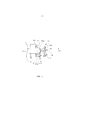
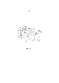
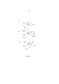
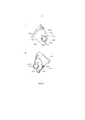
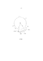
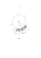
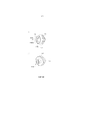
Фиг. 1 – вид сбоку в разрезе проявочного картриджа согласно варианту осуществления настоящего изобретения.FIG. 1 is a side view in section of a developing cartridge in accordance with an embodiment of the present invention.
Фиг. 2 – вид в перспективе проявочного картриджа согласно варианту осуществления настоящего изобретения.FIG. 2 is a perspective view of a developing cartridge in accordance with an embodiment of the present invention.
Фиг. 3 – вид в перспективе проявочного картриджа согласно варианту осуществления настоящего изобретения.FIG. 3 is a perspective view of a developing cartridge in accordance with an embodiment of the present invention.
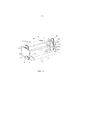
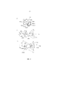
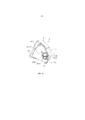
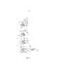
Фиг. 4 – вид сбоку в разрезе основной сборки электрофотографического устройства формирования изображения согласно варианту осуществления настоящего изобретения.FIG. 4 is a side sectional view of the main assembly of an electrophotographic image forming apparatus according to an embodiment of the present invention.
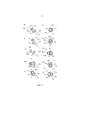
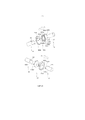
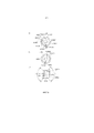
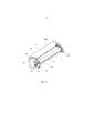
Фиг. 5 – вид в перспективе проявочного валика согласно варианту осуществления настоящего изобретения.FIG. 5 is a perspective view of a development roller according to an embodiment of the present invention.
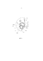
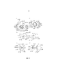
Фиг. 6 – вид перспективе и вид в продольном разрезе муфты согласно варианту осуществления настоящего изобретения.FIG. 6 is a perspective view and a longitudinal sectional view of a clutch according to an embodiment of the present invention.
Фиг. 7 – вид в перспективе проявочного опорного элемента согласно варианту осуществления настоящего изобретения.FIG. 7 is a perspective view of a development support member according to an embodiment of the present invention.
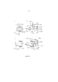
Фиг. 8 – вид в перспективе муфты согласно варианту осуществления настоящего изобретения.FIG. 8 is a perspective view of a coupling according to an embodiment of the present invention.
Фиг. 9 – вид сбоку в разрезе стороны проявочного картриджа согласно варианту осуществления настоящего изобретения.FIG. 9 is a side view in section of the side of the developing cartridge in accordance with an embodiment of the present invention.
Фиг. 10 – покомпонентное изображение элемента муфты согласно варианту осуществления настоящего изобретения.FIG. 10 is an exploded view of a clutch member in accordance with an embodiment of the present invention.
Фиг. 11 – вид в продольном разрезе проявочного картриджа согласно варианту осуществления настоящего изобретения.FIG. 11 is a longitudinal sectional view of a developing cartridge according to an embodiment of the present invention.
Фиг. 12 – вид в продольном разрезе проявочного картриджа согласно варианту осуществления настоящего изобретения.FIG. 12 is a longitudinal sectional view of a developing cartridge according to an embodiment of the present invention.
Фиг. 13 – вид в продольном разрезе проявочного картриджа согласно варианту осуществления настоящего изобретения.FIG. 13 is a longitudinal sectional view of a developing cartridge according to an embodiment of the present invention.
Фиг. 14 – вид в перспективе муфты согласно варианту осуществления настоящего изобретения.FIG. 14 is a perspective view of a coupling according to an embodiment of the present invention.
Фиг. 15 – вид в перспективе элемента ротора (в дальнейшем называемого «ротором») согласно варианту осуществления настоящего изобретения.FIG. 15 is a perspective view of a rotor element (hereinafter referred to as a “rotor”) according to an embodiment of the present invention.
Фиг. 16 – вид в перспективе ротора согласно варианту осуществления настоящего изобретения.FIG. 16 is a perspective view of a rotor according to an embodiment of the present invention.
Фиг. 17 – вид в перспективе ротора согласно варианту осуществления настоящего изобретения.FIG. 17 is a perspective view of a rotor according to an embodiment of the present invention.
Фиг. 18 показывает вид, как виден сбоку, основной сборки устройства согласно варианту осуществления настоящего изобретения.FIG. 18 shows a view, as seen from the side, of the main assembly of the device according to an embodiment of the present invention.
Фиг. 19 показывает вид основной сборки устройства согласно варианту осуществления настоящего изобретения, как виден сбоку.FIG. 19 shows a view of the main assembly of the device according to an embodiment of the present invention, as seen from the side.
Фиг. 20 показывает вид основной сборки устройства согласно варианту осуществления настоящего изобретения, как виден сбоку.FIG. 20 shows the main assembly of the device according to the embodiment of the present invention, as seen from the side.
Фиг. 21 - фигура основной сборки устройства согласно варианту осуществления настоящего изобретения, как видна сбоку.FIG. 21 is a main device assembly shape according to an embodiment of the present invention, as seen from the side.
Фиг. 22 – вид в продольном разрезе, показывающий последовательность операций зацепления между приводным валом и муфтой согласно варианту осуществления настоящего изобретения.FIG. 22 is a longitudinal sectional view showing the engagement sequence between the drive shaft and the coupling according to an embodiment of the present invention.
Фиг. 23 - покомпонентное изображение в перспективе приводного вала и муфты согласно варианту осуществления настоящего изобретения.FIG. 23 is an exploded perspective view of a drive shaft and coupling according to an embodiment of the present invention.
Фиг. 24 - покомпонентное изображение в перспективе приводного вала и муфты согласно варианту осуществления настоящего изобретения.FIG. 24 is an exploded perspective view of a drive shaft and coupling according to an embodiment of the present invention.
Фиг. 25 - вид в перспективе, показывающий последовательность операций выведения муфты из зацепления с приводным валом согласно варианту осуществления настоящего изобретения.FIG. 25 is a perspective view showing the sequence of operations for disengaging a clutch from a drive shaft according to an embodiment of the present invention.
Фиг. 26 – временная диаграмма операций по варианту осуществления настоящего изобретения.FIG. 26 is a timing diagram of the operations of an embodiment of the present invention.
Фиг. 27 – вид в перспективе муфты согласно варианту осуществления настоящего изобретения.FIG. 27 is a perspective view of a coupling according to an embodiment of the present invention.
Фиг. 28 – вид в перспективе муфты согласно варианту осуществления настоящего изобретения.FIG. 28 is a perspective view of a coupling according to an embodiment of the present invention.
Фиг. 29 – вид в перспективе приводного вала согласно варианту осуществления настоящего изобретения.FIG. 29 is a perspective view of a drive shaft according to an embodiment of the present invention.
Фиг. 30 – вид в перспективе муфты согласно варианту осуществления настоящего изобретения.FIG. 30 is a perspective view of a coupling according to an embodiment of the present invention.
Фиг. 31 – вид в перспективе муфты согласно варианту осуществления настоящего изобретения.FIG. 31 is a perspective view of a coupling according to an embodiment of the present invention.
Фиг. 32 – вид в перспективе стороны проявочного картриджа согласно варианту осуществления настоящего изобретения.FIG. 32 is a perspective view of the side of the developing cartridge in accordance with an embodiment of the present invention.
Фиг. 33 – вид в частичном разрезе проявочного картриджа и проявочного вала согласно варианту осуществления настоящего изобретения.FIG. 33 is a view in partial section of a developing cartridge and a developing shaft according to an embodiment of the present invention.
Фиг. 34 – вид в продольном разрезе, иллюстрирующий последовательность операций выемки проявочного картриджа согласно варианту осуществления настоящего изобретения.FIG. 34 is a longitudinal sectional view illustrating a process for excavating a developing cartridge according to an embodiment of the present invention.
Фиг. 35 – вид в продольном разрезе, иллюстрирующий последовательность операций зацепления между приводным валом и муфтой согласно варианту осуществления настоящего изобретения.FIG. 35 is a longitudinal sectional view illustrating the engagement sequence between the drive shaft and the coupling according to an embodiment of the present invention.
Фиг. 36 – вид в перспективе проявочного опорного элемента согласно варианту осуществления настоящего изобретения.FIG. 36 is a perspective view of a development support member according to an embodiment of the present invention.
Фиг. 37 – вид в перспективе стороны проявочного картриджа согласно варианту осуществления настоящего изобретения.FIG. 37 is a perspective view of the side of the developing cartridge in accordance with an embodiment of the present invention.
Фиг. 38 – вид в перспективе, иллюстрирующий состояние зацепления между приводным валом и муфтой согласно варианту осуществления настоящего изобретения, и вид в продольном разрезе.FIG. 38 is a perspective view illustrating the state of engagement between the drive shaft and the coupling according to the embodiment of the present invention, and a longitudinal sectional view.
Фиг. 39 – вид в перспективе проявочного опорного элемента согласно варианту осуществления настоящего изобретения.FIG. 39 is a perspective view of a development support member according to an embodiment of the present invention.
Фиг. 40 – вид в перспективе муфты согласно варианту осуществления настоящего изобретения.FIG. 40 is a perspective view of a coupling according to an embodiment of the present invention.
Фиг. 41 – вид в перспективе стороны проявочного картриджа согласно варианту осуществления настоящего изобретения.FIG. 41 is a perspective view of the side of the developing cartridge in accordance with an embodiment of the present invention.
Фиг. 42 – вид в перспективе и вид в продольном разрезе, иллюстрирующие состояние зацепления между приводным валом и муфтой согласно варианту осуществления настоящего изобретения.FIG. 42 is a perspective view and a longitudinal sectional view illustrating the state of engagement between the drive shaft and the coupling according to an embodiment of the present invention.
Фиг. 43 – покомпонентное изображение в перспективе, иллюстрирующее состояние установки муфты в проявочный опорный элемент, в варианте осуществления настоящего изобретения.FIG. 43 is an exploded perspective view illustrating the state of installation of the coupling into the developing support member in an embodiment of the present invention.
Фиг. 44 – вид в перспективе муфты согласно варианту осуществления настоящего изобретения.FIG. 44 is a perspective view of a coupling according to an embodiment of the present invention.
Фиг. 45 – вид в продольном разрезе, иллюстрирующий зацепленное состояние между проявочным валом и муфтой согласно варианту осуществления настоящего изобретения.FIG. 45 is a longitudinal sectional view illustrating the engaged state between the developing shaft and the coupling according to an embodiment of the present invention.
Фиг. 46 – вид в продольном разрезе, показывающий зацепленное состояние между приводным валом и муфтой согласно варианту осуществления настоящего изобретения.FIG. 46 is a longitudinal sectional view showing the engaged state between the drive shaft and the coupling according to an embodiment of the present invention.
Фиг. 47 – вид сбоку фланца ротора согласно варианту осуществления настоящего изобретения.FIG. 47 is a side view of a rotor flange according to an embodiment of the present invention.
Фиг. 48 – вид сбоку фланца ротора согласно варианту осуществления настоящего изобретения.FIG. 48 is a side view of a rotor flange according to an embodiment of the present invention.
Фиг. 49 иллюстрирует годограф муфты, показанной на фиг. 47, согласно варианту осуществления настоящего изобретения.FIG. 49 illustrates the hodograph of the clutch shown in FIG. 47, in accordance with an embodiment of the present invention.
Фиг. 50 – вид в разрезе приводного вала и муфты по фиг. 38, согласно варианту осуществления настоящего изобретения.FIG. 50 is a sectional view of the drive shaft and the coupling of FIG. 38, according to an embodiment of the present invention.
Фиг. 51 – иллюстрация муфты согласно варианту осуществления настоящего изобретения.FIG. 51 is an illustration of a coupling according to an embodiment of the present invention.
Фиг. 52 – вид в продольном разрезе, иллюстрирующий состояние перед зацеплением между приводным валом и муфтой, касательно варианта осуществления настоящего изобретения.FIG. 52 is a longitudinal sectional view illustrating the state before engagement between the drive shaft and the coupling, regarding an embodiment of the present invention.
Фиг. 53 – вид перспективе и вид в продольном разрезе муфты согласно варианту осуществления настоящего изобретения.FIG. 53 is a perspective view and a longitudinal sectional view of a coupling according to an embodiment of the present invention.
Фиг. 54 – вид в перспективе муфты согласно варианту осуществления настоящего изобретения.FIG. 54 is a perspective view of a coupling according to an embodiment of the present invention.
Фиг. 55 – вид в продольном разрезе, показывающий зацепленное состояние между приводным валом и муфтой согласно варианту осуществления настоящего изобретения.FIG. 55 is a longitudinal sectional view showing the engaged state between the drive shaft and the coupling according to an embodiment of the present invention.
Фиг. 56 – вид в перспективе, показывающий последовательность операций зацепления между приводным валом и муфтой согласно варианту осуществления настоящего изобретения.FIG. 56 is a perspective view showing the sequence of operations of the engagement between the drive shaft and the coupling according to the embodiment of the present invention.
Фиг. 57 – вид в перспективе проявочного картриджа согласно варианту осуществления настоящего изобретения.FIG. 57 is a perspective view of a developing cartridge according to an embodiment of the present invention.
Фиг. 58 – вид в перспективе проявочного картриджа согласно варианту осуществления настоящего изобретения.FIG. 58 is a perspective view of a developing cartridge according to an embodiment of the present invention.
Фиг. 59 – вид в перспективе, иллюстрирующий ведущую входную шестерню согласно варианту осуществления настоящего изобретения.FIG. 59 is a perspective view illustrating the driving input gear according to the embodiment of the present invention.
Фиг. 60 – вид в перспективе проявочного картриджа согласно варианту осуществления настоящего изобретения.FIG. 60 is a perspective view of a developing cartridge according to an embodiment of the present invention.
Фиг. 61 – вид перспективе и вид в продольном разрезе муфты согласно варианту осуществления настоящего изобретения.FIG. 61 is a perspective view and a longitudinal sectional view of a coupling according to an embodiment of the present invention.
Фиг. 62 – покомпонентный продольный разрез муфты и ведущей входной шестерни согласно варианту осуществления настоящего изобретения.FIG. 62 is an exploded longitudinal section of a clutch and drive input gear according to an embodiment of the present invention.
Фиг. 63 - покомпонентное изображение в перспективе муфты и элемента подшипника согласно варианту осуществления настоящего изобретения.FIG. 63 is an exploded perspective view of the coupling and bearing member according to the embodiment of the present invention.
Фиг. 64 – вид в продольном разрезе проявочного картриджа согласно варианту осуществления настоящего изобретения.FIG. 64 is a longitudinal sectional view of a developing cartridge according to an embodiment of the present invention.
Фиг. 65 – вид в продольном разрезе проявочного картриджа согласно варианту осуществления настоящего изобретения.FIG. 65 is a longitudinal sectional view of a developing cartridge according to an embodiment of the present invention.
Фиг. 66 – вид в перспективе, показывающий зацепленное состояние проявочного валика и муфты согласно варианту осуществления настоящего изобретения.FIG. 66 is a perspective view showing the engaged state of the developing roller and the sleeve according to the embodiment of the present invention.
Фиг. 67 – вид в продольном разрезе, иллюстрирующий последовательность операций зацепления между муфтой и приводным валом согласно варианту осуществления настоящего изобретения.FIG. 67 is a longitudinal sectional view illustrating the engagement sequence between the coupling and the drive shaft according to an embodiment of the present invention.
Фиг. 68 - вид перспективе приводного вала и муфты согласно варианту осуществления настоящего изобретения.FIG. 68 is a perspective view of a drive shaft and coupling according to an embodiment of the present invention.
Фиг. 69 – вид в продольном разрезе, иллюстрирующий последовательность операций расцепления муфты с приводным валом согласно варианту осуществления настоящего изобретения.FIG. 69 is a longitudinal sectional view illustrating the process of disengaging a coupling with a drive shaft according to an embodiment of the present invention.
Фиг. 70 – вид в перспективе проявочного картриджа согласно варианту осуществления настоящего изобретения.FIG. 70 is a perspective view of a developing cartridge according to an embodiment of the present invention.
Фиг. 71 – вид в перспективе стороны проявочного картриджа согласно варианту осуществления настоящего изобретения (боковая пластина картриджа изъята).FIG. 71 is a perspective view of the side of the developing cartridge in accordance with an embodiment of the present invention (the side plate of the cartridge is removed).
Фиг. 72 – вид в перспективе, иллюстрирующий ведущую входную шестерню согласно варианту осуществления настоящего изобретения.FIG. 72 is a perspective view illustrating a driving input gear according to an embodiment of the present invention.
Фиг. 73 – вид сбоку основной сборки устройства согласно варианту осуществления настоящего изобретения.FIG. 73 is a side view of a main assembly of an apparatus according to an embodiment of the present invention.
Фиг. 74 – вид сбоку основной сборки устройства согласно варианту осуществления настоящего изобретения.FIG. 74 is a side view of a main assembly of an apparatus according to an embodiment of the present invention.
Фиг. 75 – вид в разрезе основной сборки устройства согласно варианту осуществления настоящего изобретения.FIG. 75 is a sectional view of the main assembly of the device according to the embodiment of the present invention.
Фиг. 76 – вид перспективе и вид в продольном разрезе, иллюстрирующие муфту согласно варианту осуществления настоящего изобретения.FIG. 76 is a perspective view and a longitudinal sectional view illustrating a sleeve according to an embodiment of the present invention.
Фиг. 77 – вид сбоку и вид в перспективе муфты согласно варианту осуществления настоящего изобретения.FIG. 77 is a side view and a perspective view of a clutch according to an embodiment of the present invention.
Фиг. 78 – вид в продольном разрезе, иллюстрирующий последовательность операций зацепления и последовательность операций расцепления между приводным валом и муфтой согласно варианту осуществления настоящего изобретения.FIG. 78 is a longitudinal sectional view illustrating the engagement sequence and the decoupling sequence between the drive shaft and the coupling according to an embodiment of the present invention.
ПОДРОБНОЕ ОПИСАНИЕDETAILED DESCRIPTION
НАИЛУЧШИЙ ВАРИАНТ ОСУЩЕСТВЛЕНИЯ ИЗОБРЕТЕНИЯBEST MODE FOR CARRYING OUT THE INVENTION
Ниже, проявочный картридж, электрофотографическое устройство формирования изображений и элемент муфты согласно настоящему изобретению будут описаны со ссылкой на чертежи.Below, a developing cartridge, an electrophotographic image forming apparatus, and a clutch member according to the present invention will be described with reference to the drawings.
В следующих вариантах осуществления, проявочный картридж имеет тип, в котором пользователь может устанавливать и снимать проявочный картридж относительно основной сборки устройства. Однако, настоящее изобретение также применимо к проявочному устройству, которое используется в состоянии, в котором оно установлено и закреплено в основной сборке.In the following embodiments, the developing cartridge has a type in which the user can install and remove the developing cartridge relative to the main assembly of the device. However, the present invention is also applicable to a developing device, which is used in the state in which it is installed and fixed in the main assembly.
Кроме того, настоящее изобретение особенно применимо к одиночному элементу муфты (например, таким, как показанные на фиг. 6(a), 14(a3), 28(c), 30 и 77(b)), проявочному устройству (проявочному картриджу) (например, таким, как показанные на фиг. 2, 57 и 60) и электрофотографическому устройству формирования изображений (например, таким, как показанные на фиг. 5 и 75).In addition, the present invention is particularly applicable to a single clutch member (eg, such as shown in FIG. 6 (a), 14 (a3), 28 (c), 30, and 77 (b)), a developing device (developing cartridge) (for example, such as shown in Fig. 2, 57 and 60) and electrophotographic device imaging (for example, such as shown in Fig. 5 and 75).
Вариант 1 осуществления
(1) Краткое описание проявочного картриджа (проявочного устройства)(1) A brief description of the developing cartridge (developing device)
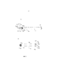
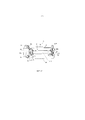
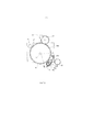
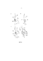
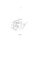
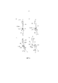
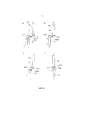
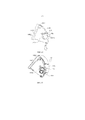
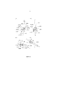
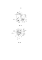
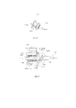
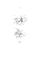
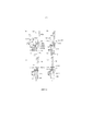
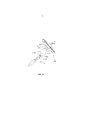
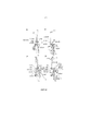
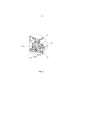
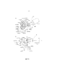
Прежде всего, со ссылкой на фиг. с 1 по 4, будет описан проявочный картридж B в качестве проявочного устройства, к которому применяется вариант осуществления настоящего изобретения (в дальнейшем, указываемого ссылкой просто как «картридж»). Фиг. 1 – вид в разрезе картриджа B. Фиг. 2 и 3 – виды в перспективе картриджа B. Фиг. 4 – вид в разрезе основной сборки A цветного электрофотографического устройства формирования изображений (в дальнейшем, указываемой ссылкой как «основная сборка устройства»).First of all, with reference to FIG. 1 to 4, a developing cartridge B as a developing device to which an embodiment of the present invention is applied (hereinafter referred to simply as a “cartridge”) will be described. FIG. 1 is a sectional view of cartridge B. FIG. 2 and 3 are perspective views of the cartridge B. FIG. 4 is a sectional view of the main assembly A of a color electrophotographic image forming device (hereinafter referred to as “the main assembly of the device”).
Этот картридж B может устанавливаться на и сниматься с ротора C, предусмотренного у основной сборки A устройства, пользователем.This cartridge B can be mounted on and removed from the rotor C provided at the main assembly A of the device by the user.
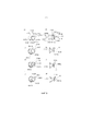
Со ссылкой на фиг. с 1 по 3, картридж B включает в себя проявочный валик 110. Проявочный валик вращается, принимая поворотное усилие из основной сборки A устройства через механизм муфты, описанный позже, во время функции проявления. В обойме 114 вмещения проявителя, размещен проявитель t предопределенного цвета. Этот проявитель подается в камеру 113a проявителя в предопределенном количестве посредством вращения элемента 116 перемешивания. Подаваемый проявитель подводится на поверхность проявочного валика вращением губчатого валика 115 подачи проявителя в камере 113a проявителя. Этот проявитель формируется в тонкий слой, будучи подаваемым электрическими зарядами, благодаря трибоэлектрическому заряду между тонкой пластинчатой проявочной планкой 112 и проявочным валиком 110. Проявитель, сформированный тонким слоем на проявочном валике 110, подается в положение проявления посредством вращения. Прикладыванием предопределенного напряжения смещения проявления к проявочному валику 110, проявляется электростатическое скрытое изображение, сформированное на электрофотографическом фоточувствительном элементе 107 (в дальнейшем, указываемом ссылкой как «фоточувствительный барабан»). То есть, электростатическое скрытое изображение проявляется проявочным валиком 110.Referring to FIG. 1 to 3, the cartridge B includes a developing
Кроме того, проявитель, который не вносит вклад в проявление электростатического скрытого изображения, то есть, остаточный проявитель, снимаемый на поверхности проявочного валика 110, удаляется валиком 115 подачи проявителя. Одновременно, свежий проявитель подается на поверхность проявочного валика 110 валиком 115 подачи проявителя. Таким образом, успешно выполняется операция проявления.In addition, the developer, which does not contribute to the development of the electrostatic latent image, that is, the residual developer taken on the surface of the developing
Картридж B включает в себя проявочный узел 119. Проявочный узел 119 включает в себя обойму 113 проявочного устройства и обойму 114 вмещения проявителя. Проявочный узел 119 дополнительно включает в себя проявочный валик 110, проявочную планку 112, валик 1115 подачи проявителя, камеру 113a проявителя, обойму 14 вмещения проявителя и элемент 116 перемешивания.The cartridge B includes a developing
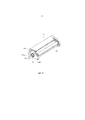
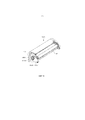
Проявочный валик 110 является вращаемым вокруг осевой линии L1.The developing
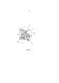
Здесь, проявочный картридж B установлен пользователем в часть 130A вмещения проявочного картриджа, предусмотренную у механизма C выбора угла поворота (проявочного ротора) основной сборки A устройства. В это время, как описано позже, приводной вал основной сборки A устройства и элемент муфты в качестве части передачи поворотной движущей силы картриджа B присоединены друг к другу во взаимосвязи с таким действием, что картридж B расположен в предопределенном положении (положении, противостоящем фоточувствительному барабану) посредством проявочного ротора C (механизма выбора угла поворота). Таким образом, проявочный валик 110, и тому подобное, вращаются, принимая движущую силу из основной сборки A устройства.Here, the developing cartridge B is set by the user to the accommodating portion of the developing
(2) Описание электрофотографического устройства формирования изображений(2) Description of electrophotographic image forming apparatus.
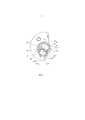
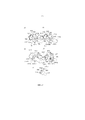
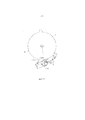
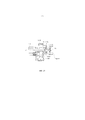
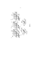
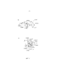
По фиг. 4 будет описано цветное электрофотографическое устройство формирования изображений, использующее описанный проявочный картридж B. В последующем, будет произведено описание, беря цветной лазерный принтер в качестве примера цветного электрофотографического устройства формирования изображений.According to FIG. 4, a color electrophotographic image forming apparatus using the described developing cartridge B will be described. Subsequently, a description will be made, taking a color laser printer as an example of a color electrophotographic image forming apparatus.
Как показано на фиг. 4, множество картриджей B (B1, B2, B3, B4), вмещающих проявители (тонеры), разные по цвету, установлено в ротор C. Установка и снятие картриджа B по отношению к ротору C выполняются пользователем. Посредством вращения ротора C, картридж B, вмещающий проявитель предопределенного цвета, располагается напротив фоточувствительного барабана 107. Затем, проявляется электростатическое скрытое изображение, сформированное на фоточувствительном барабане 107. Проявленное изображение переносится на записывающий материал S. Эта операция проявления и переноса выполняется для каждого из цветов. Как результат, получается цветное изображение. Ниже, будет приведено частичное описание. Записывающий материал S является материалом, на котором может формироваться изображение, и, например, включает в себя бумагу, лист OHP, и тому подобное.As shown in FIG. 4, a plurality of B cartridges (B1, B2, B3, B4) accommodating developers (toners), different in color, are installed in the rotor C. The installation and removal of the cartridge B relative to the rotor C are performed by the user. By rotating the rotor C, the cartridge B containing the developer of a predetermined color is located opposite the
Со ссылкой на фиг. 4, фоточувствительный барабан 107 облучается светом на основании информации об изображении из оптического средства 101. Посредством этого облучения, электростатическое скрытое изображение формируется на фоточувствительном барабане 107. Электростатическое скрытое изображение проявляется с помощью проявителя проявочным валиком 110. Изображение проявителя, сформированное на фоточувствительном барабане 107, переносится на элемент промежуточного переноса.Referring to FIG. 4, the
Затем, изображение проявителя, перенесенное на ленту 104a промежуточного переноса в качестве элемента промежуточного переноса, переносится на записывающий материал S средством вторичного переноса. Затем, записывающий материал S, на который перенесено изображение проявителя, транспортируется в средство 105 фиксации, включающее в себя нажимной валик 105a и нагревательный валик 105b. Изображение проявителя, перенесенное на записывающий материал S, фиксируется на записывающем материале S. После фиксации, записывающий материал S выгружается на лоток 106.Then, the developer image transferred to the
Этап формирования изображения будет описан более точно.The imaging step will be described more accurately.
Синхронно с вращением ленты 104a промежуточного переноса, фоточувствительный барабан 107 вращается против часовой стрелки (фиг. 4). Затем, поверхность фоточувствительного барабана 107 электрически равномерно заряжается зарядным валиком 108. Поверхность фоточувствительного барабана 107 облучается светом в зависимости от информации об изображении, например, о желтом изображении, оптическим средством 101 (экспонирования). Таким образом, желтое электростатическое скрытое изображение формируется на фоточувствительном барабане 107.Synchronously with the rotation of the
Средство 101 экспонирования составлено, как изложено ниже. Средство 101 экспонирования облучает фоточувствительный барабан 107 светом на основе информации об изображении, считанной из внешнего устройства (не показано). Как результат, электростатическое скрытое изображение формируется на фоточувствительном барабане 107. Средство 101 экспонирования включает в себя лазерный диод, многогранное зеркало, электродвигатель сканера, линзу формирования изображения, отражательное зеркало.The exposure means 101 is composed as follows. The exposure means 101 irradiates the
Сигнал изображения отправляется из непоказанного внешнего устройства. Посредством этой операции, лазерный диод испускает свет в зависимости от сигнала изображения, а многогранное зеркало облучается светом (в качестве света изображения). Многогранное зеркало вращается с высокой частотой вращения электродвигателем сканера, чтобы отражать свет изображения, так что поверхность фоточувствительного барабана 107 избирательно экспонируется светом изображения через линзу формирования изображения и отражательное зеркало. Как результат, электростатическое скрытое изображение, зависящее от информации об изображении, формируется на фоточувствительном барабане 107.The image signal is sent from a not-shown external device. Through this operation, a laser diode emits light depending on the image signal, and a multifaceted mirror is irradiated with light (as image light). A multifaceted mirror rotates at a high speed with the scanner motor to reflect the image light, so that the surface of the
Одновременно с формированием этого электростатического скрытого изображения, ротор C вращается, тем самым, желтый картридж B1 перемещается в положение проявления. Затем, предопределенное напряжение смещения проявления прикладывается к проявочному валику 110. Как результат, желтый проявитель наносится на электростатическое скрытое изображение, так что электростатическое скрытое изображение проявляется желтым проявителем. После этого, напряжение смещения с полярностью, противоположной таковой у проявителя, прикладывается к нажимному валику 104j (валику первичного переноса) относительно ленты 104a промежуточного переноса, так что изображение желтого проявителя на фоточувствительном барабане 107 первично переносится на ленту 104a промежуточного переноса.Simultaneously with the formation of this electrostatic latent image, the rotor C rotates, thereby, the yellow cartridge B1 moves to the developing position. Then, a predetermined developing bias voltage is applied to the
Как описано выше, после того, как первичный перенос изображения желтого проявителя завершен, ротор C вращается. Как результат, следующий картридж B2 перемещается, чтобы располагаться в положении напротив фоточувствительного барабана 107. Описанная выше последовательность операций выполняется по отношению к пурпурному картриджу B2, голубому картриджу B3 и черному картриджу B4. Таким образом, повторяя последовательность операций для каждого из пурпурного цвета, голубого цвета и черного цвета, изображения проявителя четырех цветов накладываются на ленту 104a промежуточного переноса.As described above, after the primary transfer of the yellow developer image is completed, the rotor C rotates. As a result, the next cartridge B2 is moved to be positioned opposite the
В этой связи, желтый картридж B1 вмещает желтый проявитель и формирует желтое изображение проявителя. Пурпурный картридж B2 вмещает пурпурный проявитель и формирует пурпурное изображение проявителя. Голубой картридж B3 вмещает голубой проявитель и формирует голубое изображение проявителя. Черный картридж B4 вмещает черный проявитель и формирует черное изображение проявителя.In this regard, the yellow cartridge B1 accommodates the yellow developer and forms a yellow image of the developer. The magenta cartridge B2 accommodates a magenta developer and forms a magenta developer image. The B3 cyan cartridge accommodates a cyan developer and forms a cyan developer image. The black B4 cartridge holds the black developer and forms a black developer image.
Во время формирования изображения, описанного выше, валик 104b вторичного переноса находится в неконтактном состоянии с лентой 104a промежуточного переноса. Очищающий зарядный валик 104f также находится в неконтактном состоянии с лентой 104a промежуточного переноса.During imaging described above, the
После того, как изображения проявителя четырех цветов сформированы на ленте 104a промежуточного переноса, валик 104b вторичного переноса прижимается к ленте 104a промежуточного переноса (фиг. 4). В синхронизме с нажимным касанием валика 104b вторичного переноса, записывающий материал S, ожидающий в положении по соседству от пары 103e валиков записи, отправляется в зазор между лентой 104a переноса и валиком 104b переноса. Одновременно, записывающий материал S подается из кассеты 103a подающим роликом 103b и парой 103c транспортировочных роликов в качестве средства 103 подачи (транспортировки).After the four-color developer images are formed on the
Непосредственно перед парой 103e валиков записи расположен датчик 99. Датчик 99 обнаруживает передний край записывающего материала S и останавливает вращение пары 103e валиков записи, таким образом, переводя записывающий материал S в состояние эксплуатационной готовности в предопределенном положении.Immediately in front of the pair of
К валику 104b переноса приложено напряжение смещения полярности, противоположной таковой у проявителя, так что изображения проявителя на ленте 104a переноса одновременно вторично переносятся на транспортируемый записывающий материал S.A transfer voltage polarity opposite to that of the developer is applied to the
Записывающий материал S, на который перенесены изображения проявителя, и транспортируется в средство 105 фиксации через узел 103f транспортерной ленты. Посредством средства 105 фиксации выполняется фиксация изображений проявителя. Записывающий материал S, подвергнутый фиксации, выгружается на разгрузочный лоток 106, расположенный в верхней части основной сборки устройства, парой 103g разгрузочных роликов. Таким образом, формирование изображения записывающего материала S завершается.The recording material S, onto which the developer images have been transferred, is transported to the fixing means 105 through the conveyor belt unit 103f. By means of the
После завершения вторичного переноса, зарядный валик 104f прижимается к ленте 104a переноса, так что поверхность ленты 104a и проявитель, оставшийся на поверхности ленты 104a снабжаются предопределенным напряжением смещения. Как результат, остаточный электрический заряд удаляется.After completion of the secondary transfer, the charging roller 104f is pressed against the
Остаточный проявитель, подвергнутый удалению заряда, электростатически повторно переносится с ленты 104a на фоточувствительный барабан 107 через зазор первичного переноса. Как результат, поверхность ленты 104a очищается. Остаточный проявитель, повторно перенесенный на фоточувствительный барабан 107 после вторичного переноса, удаляется очищающей планкой 117a, соприкасающейся с фоточувствительным барабаном 107. Удаленный проявитель собирается в коробе 107d остаточного проявителя через транспортировочный канал (не показан).The residual charge-removed developer is electrostatically re-transferred from the
В этой связи, вмещающая часть 130a является камерой, в которой вмещен описанный выше картридж B, и предусмотрена у ротора C в множестве положений. Ротор C вращается в одном направлении в состоянии, в котором картридж B установлен в камере. Как результат, элемент муфты (описанный позже) картриджа B присоединяется к приводному валу 180, предусмотренному у основной сборки A устройства и отсоединяется от приводного вала 180. Картридж B (проявочный валик 110) перемещается в направлении, по существу перпендикулярном направлению осевой линии L3 приводного вала 180 в зависимости от перемещения ротора C в одном направлении.In this regard, the enclosing portion 130a is a camera in which the above-described cartridge B is contained and provided at the rotor C in a plurality of positions. The rotor C rotates in one direction in the state in which the cartridge B is mounted in the chamber. As a result, the coupling member (described later) of the cartridge B is attached to the
(3) Строение проявочного валика(3) Structure of the development roller
Затем, со ссылкой на фиг. 5(a) и 5(b), будет описано строение проявочного валика 110. Фиг. 5(a) – вид в перспективе проявочного валика 110, как виден со стороны приема движущей силы с основной сборки на проявочный валик 110 (в дальнейшем, указываемой ссылкой просто как «приводная сторона»). Фиг. 5(b) – вид в перспективе проявочного валика 110, как виден со стороны, противоположной от приводной стороны по отношению к осевому направлению проявочного валика 110 (в дальнейшем, указываемой ссылкой как «неприводная сторона»).Then, with reference to FIG. 5 (a) and 5 (b), the structure of the
Проявочный валик 110 включает в себя проявочный вал 153 и резиновую часть 110a. Проявочный вал 153 сформирован из электропроводящего материала, такого как железо, или тому подобное, в форме вытянутого вала и покрытого резиновой частью 110a на участке за исключением обоих оконечных частей по отношению к осевому направлению. Проявочный вал 153 с возможностью вращения поддерживается каркасом 113 проявочного устройства благодаря подшипникам (не показанным) в обеих оконечных частях 153d1 и 153d2 зацепления. Кроме того, картридж 150, описанный позже, расположен в оконечной части 153b на приводной стороне. Картридж 150 вводится в зацепление с штифтом 155 передачи поворотного усилия, описанным позже, для передачи движущей силы. Резиновая часть 110 коаксиально покрывает проявочный вал 153. Резиновая часть 110 переносит проявитель и проявляет электростатическое скрытое изображение, прикладывая напряжение смещения к проявочному валу 153.The developing
Элементы 136 и 137 регулировки ширины зазора являются элементами для стабилизации ширины зазора проявочного валика 110 относительно фоточувствительного барабана 107 на постоянном значении.
Непоказанные подшипники расположены в обеих оконечных частях 153d1 и 153d2 проявочного валика 110, с тем чтобы с возможностью вращения поддерживать проявочный валик 110 на каркасе 113 проявочного устройства (фиг. 1).Bearings not shown are located in both end portions 153d1 and 153d2 of the developing
Проявочная шестерня (не показана) расположена в оконечной части 153d1 приводной стороны проявочного валика 110 и прикреплена к проявочному валу 153. Непоказанная проявочная шестерня передает поворотное усилие, принятое из основной сборки A устройства, на проявочный валик 110, на другие элементы вращения (например, валик 115 подачи проявителя, элемент перемешивания, и тому подобное) проявочного картриджа B.A development gear (not shown) is located in the terminal part 153d1 of the drive side of the
Затем, будет более подробно описана оконечная часть приводной стороны проявочного вала 153, на котором подвижным (с возможностью шарнирного поворота, с возможностью качания) образом установлен картридж 150. Оконечная часть 153b имеет сферическую форму, так что осевая линия L2 картриджа 150 (описанного позже) может плавно наклоняться. По соседству от конца проявочного вала 153, штифт 155 передачи движущей силы для приема поворотного усилия с картриджа 150 расположен в направлении, пересекающем осевую линию L1 проявочного вала 153.Then, the end part of the drive side of the
Штифт 155 в качестве части передачи поворотного усилия сформирован из металла и прикреплен к проявочному валу 153 посредством способа, такого как прессовая посадка, соединение сваркой или тому подобное. Положение крепления может быть любым положением, в котором может передаваться движущая сила (поворотное усилие), то есть, направлением, пересекающем осевую линию L1 проявочного вала (проявочного валика). Желательно, чтобы штифт 155 проходил через сферический центр P2 (фиг. 10b) оконечной части 153b проявочного вала 153. Это происходит потому, что диаметр передачи поворотного усилия всегда удерживается на постоянном уровне, даже в случае, где осевая линия L1 проявочного вала 153 и осевая линия L2 картриджа 150 до некоторой степени отклонены друг от друга. По этой причине, можно реализовать стабильную передачу поворотного усилия. Штифт передачи поворотного усилия может быть предусмотрен в любых местах. Однако, для того чтобы надежно передавать вращающий момент (движущую силу) и улучшать качество сборки, одиночный штифт 155 применяется в этом варианте осуществления. Штифт 155 пропущен через центр P2 торцевой сферической поверхности 153b. Как результат, штифт 155 (155a1 и 155a2) расположен, с тем чтобы выставляться в местах, противолежащих на 180 градусов друг от друга на периферийной поверхности приводного вала. То есть, поворотное усилие передается в двух точках. В этом варианте осуществления, штифт 155 прикреплен на стороне оконечной части в пределах 5 мм от торца вала 153 барабана. Однако, настоящее изобретение не ограничено этим.The
В этой связи, электрический контакт проявления стороны основной сборки (не показан) расположен в основной сборке A устройства, с тем чтобы контактировать с оконечной частью 153c неприводной стороны электропроводящего проявочного вала 153. Электрический контакт (не показан) проявочного картриджа и электрический контакт проявления стороны основной сборки приведены в соприкосновение друг с другом. Таким образом, высоковольтное напряжение смещения подводится из основной сборки A устройства к проявочному валику 110.In this regard, the electrical manifestation contact of the side of the main assembly (not shown) is located in the apparatus main assembly A so as to contact the non-driving side of the electrically
(4) Описание части передачи поворотной движущей силы (муфты, элемента муфты)(4) Description of the part of the transmission of the rotary driving force (coupling, coupling element)
Вариант осуществления муфты (элемента муфты), которая является частью передачи поворотной движущей силы в качестве главной составляющей части настоящего изобретения, будет описан со ссылкой на фиг. с 6(a) по 6(f). Фиг. 6(a) - вид в перспективе муфты, как видна со стороны основной сборки устройства, а фиг. 6(b) – вид в перспективе муфты, как видна со стороны фоточувствительного барабана. Фиг. 6(c) – вид муфты, как видна с направления, перпендикулярного направлению оси L2 вращения муфты. Фиг. 6(d) - вид сбоку муфты, как видна со стороны основной сборки устройства, а фиг. 6(e) – вид муфты, как видна со стороны фоточувствительного барабана. Фиг. 6(f) – вид в разрезе муфты, взятый вдоль линии S3 - S3, показанной на фиг. 6(d).An embodiment of a clutch (clutch member), which is part of the transmission of a pivotal driving force as the main component of the present invention, will be described with reference to FIG. from 6 (a) to 6 (f). FIG. 6 (a) is a perspective view of the clutch, as seen from the main assembly of the device, and FIG. 6 (b) is a perspective view of the clutch, as seen from the side of the photosensitive drum. FIG. 6 (c) is a view of the coupling, as seen from a direction perpendicular to the direction of the axis of rotation L2 of the coupling. FIG. 6 (d) is a side view of the coupling, as seen from the main assembly of the device, and FIG. 6 (e) - view of the clutch, as seen from the side of the photosensitive drum. FIG. 6 (f) is a sectional view of the coupling taken along the line S3-S3 shown in FIG. 6 (d).
Проявочный картридж B съемным образом устанавливается в часть 130a вмещения картриджа в роторе C, предусмотренном в основной сборке A устройства. Эта установка выполняется пользователем. Ротор C вращательно приводится в движение и останавливается в положении, в котором картридж B достигает предопределенного положения (положения проявления, в котором картридж B расположен напротив фоточувствительного барабана 107). Посредством этой операции, муфта 150 (элемент муфты) приводится в зацепление с приводным валом 180, предусмотренным у основной сборки A устройства. Кроме того, ротор C вращается в одном направлении, чтобы перемещать картридж B из предопределенного положения (положения проявления). То есть, картридж B отводится от предопределенного положения. Как результат, муфта 150 отодвигается в сторону от приводного вала 180. Муфта 150 принимает поворотное усилие с электродвигателя 64 (фиг. 17), предусмотренного у основной сборки A устройства, в состоянии зацепления с приводным валом 180. Муфта 150 передает поворотное усилие на проявочный валик 110. Как результат, проявочный валик 110 вращается движущей силой, принятой из основной сборки A устройства.The developing cartridge B is removably mounted to the cartridge holding portion 130a in the rotor C provided in the apparatus main assembly A. This installation is done by the user. The rotor C is rotationally driven and stops at a position in which the cartridge B reaches a predetermined position (development position, in which the cartridge B is located opposite the photosensitive drum 107). Through this operation, the coupling 150 (coupling element) is engaged with the
Как описано выше, приводной вал 180 имеет штифт 182 (часть прикладывания поворотного усилия) и вращается электродвигателем 64.As described above, the
Материалом для муфты 150 является полимерный материал, такой как полиацеталь, поликарбонат, или тому подобное. Для того чтобы усилить жесткость муфты 150, также можно усиливать жесткость посредством включения стекловолокна или тому подобного в полимерный материал, в зависимости от крутящего момента нагрузки. Кроме того, также можно применять металлический материал. Таким образом, материал для муфты 150 может быть выбираемым надлежащим образом. Однако, изготовленная из полимера муфта может легко обрабатываться, так что соответственные картриджи в этом варианте осуществления формируются из полимерного материала.
Муфта 150 главным образом содержит три части.The
Первая часть является зацепляемой с приводным валом 180 (который будет описан в дальнейшем), как показано на фиг. 6(c), и она является ведомой частью 150a для приема поворотного усилия с штифта 182 передачи поворотного усилия, который является частью прикладывания поворотного усилия (частью передачи поворотного усилия стороны основной сборки), предусмотренной на приводном валу 180. В дополнение, вторая часть является зацепляемой с штифтом 155, предусмотренным у вала 153 проявочного устройства, и она является ведущей частью 150b для передачи поворотного усилия на проявочный валик 110. В дополнение, третья часть является промежуточной частью 150c для соединения ведомой части 150a и ведущей части 150b друг с другом (фиг. 8 (c) и (f)).The first part is engaged with the drive shaft 180 (which will be described later), as shown in FIG. 6 (c), and it is the driven
Как показано на фиг. 6(f) ведомая часть 150a снабжена частью 150m проема вставки приводного вала, которая расширяется навстречу оси L2 вращения. Ведущая часть 150b имеет часть 150i проема вставки вала проявочного устройства.As shown in FIG. 6 (f), the driven
Проем 150m определен конической поверхностью 150f приема приводного вала, которая расширяется по направлению к стороне приводного вала 180 (фиг. с 9 по 13). Поверхность 150f приема составляет выемку 150z, как показано на фиг. 6(f). Выемка 150z включает в себя проем 150m в положении, противоположном от проявочного валика 110 по отношению к направлению оси L2.The
Посредством этого, независимо от фазы вращения проявочного валика 110 в картридже B, муфта 150 может двигаться (поворачиваться) между угловым положением перед зацеплением (фиг. 22(a)), угловым положением передачи поворотного усилия (фиг. 22(d)), и угловым положением расцепления (фиг. 25 (a) (d)) относительно оси L3 приводного вала 180, без препятствия со стороны свободной оконечной части 182a приводного вала 180. Подробности этого будут описаны в дальнейшем.Through this, regardless of the phase of rotation of the developing
Множество выступов 150d (150d1-150d4) (частей зацепления) предусмотрено с равными промежутками на окружности вокруг оси L2 на, торцевой поверхности выемки 150z. Между соседними выступами 150d, предусмотрены входные части 150k (150k1, 150k2, 150k3, 150k4). Промежуток между соседними выступами 150d1-150d4 является большим, чем наружный диаметр штифта 182, с тем чтобы принимались штифты 182 передачи поворотного усилия, предусмотренные у приводного вала 180 (части прикладывания поворотного усилия). Штифты являются частями прикладывания поворотного усилия. Выемки между соседними выступами являются входными частями 150k1-150k4. Когда поворотное усилие передается на муфту 150 с приводного вала 180, штифты 182 принимаются любыми из входных частей 150k1-150k4. В дополнение, на фиг. 6(d), поверхности 150e (150e1-150e4) приема поворотного усилия (части приема поворотного усилия) установлены выше по ходу относительно направления (X1) по часовой стрелке каждого выступа 150d. Поверхность 150e1-150e4 приема расширяется в направлении, пересекающемся с направлением вращения муфты 150. Более точно, выступ 150d1 имеет поверхность 150e1 приема, выступ 150d2 имеет поверхность 150e2 приема, выступ 150d3 имеет поверхность 150e3 приема, и выступ 150d4 имеет поверхность 150e4 приема. В состоянии, где приводной вал 180 вращается, штифт 182a1, 182a2 соприкасается с любой из поверхностей 150e приема. Поступая таким образом, поверхность 150e приема, подвергнутая прикосновению штифта 182a1, 182a2, толкается штифтом 182. Посредством этого, муфта 150 вращается вокруг оси L2.A plurality of
Для того, чтобы как можно больше стабилизировать крутящий момент передачи, передаваемый на муфту 150, желательно располагать поверхности 150e приема поворотного усилия на фонтомном круге (одной и той же окружности), который имеет центр O на оси L2 (фиг. 6(d)). Посредством этого, радиус передачи поворотного усилия постоянен, и крутящий момент, передаваемый на муфту 150, стабилизируется. В дополнение, что касается выступов 150d, предпочтительно, чтобы положение муфты 150 было стабилизировано посредством равновесия сил, которые принимает 150 муфта. По этой причине, в этом варианте осуществления, поверхности 150e приема расположены в диаметрально противоположных положениях (180 градусов). Более точно, в этом варианте осуществления, поверхность 150e1 приема и поверхность 150e3 приема диаметрально противоположны относительно друг друга, а поверхность 150e2 приема и поверхность 150e4 диаметрально противоположны относительно друг друга. Посредством этой компоновки, силы, которые принимает муфта 150, составляют пару сил. Поэтому, муфта 150 может продолжать вращательное движение, принимая только пару сил. По этой причине, муфта 150 может вращаться без необходимости задания по положению ее оси L2 вращения. В дополнение, что касается их количества, до тех пор, пока штифты 182 приводного вала 180 (часть прикладывания поворотного усилия) могут входить во входные части 150k (150k1-150k2), его можно выбирать подходящим образом. В этом варианте осуществления, как показано на фиг. 6, предусмотрены четыре поверхности приема. Этот вариант осуществления не ограничен этим примером. Например, поверхностям 150e приема (выступам 150d1 - 150d4) не обязательно располагаться на одной и той же окружности (фантомной окружности C1 и фиг. 6(d)). Либо, не обязательно располагать в диаметрально противоположных положениях. Однако, результаты, описанные выше, могут быть предоставлены размещением поверхностей 150e приема, как описано выше.In order to stabilize the transmission torque transmitted to the
Здесь, в этом варианте осуществления, диаметр штифта приблизительно равен 2 мм, а круговая длина входной части 150k приблизительно равна 8 мм. Круговая длина входной части 150k является промежутком между соседними выступами 150d (на фантомном круге). Размеры не являются ограничивающими настоящее изобретение.Here, in this embodiment, the pin diameter is approximately 2 mm and the circular length of the
Подобно проему 150m, часть 150l проема вставки вала проявочного устройства имеет коническую поверхность 150i приема поворотного усилия в качестве расширенной части, которая расширяется в сторону вала 153 проявочного устройства. Поверхность 150i приема составляет выемку 150q, как показано на фиг. 6(f).Like the
Посредством этого, независимо от фазы вращения проявочного валика 110 в картридже B, муфта 150 может двигаться (поворачиваться, качаться) между угловым положением передачи поворотного усилия, угловым положением перед зацеплением, и угловым положением расцепления относительно оси L1, не подвергаясь препятствию свободной оконечной частью вала 153 проявочного устройства. Выемка 150q в проиллюстрированном примере создана конической поверхностью 150i приема, которую она имеет центрирующейся по оси L2. Проемы 150g1 или 150g2 позиции готовности («проемы») предусмотрены на поверхности 150i приема (фиг. 6 (b)). Что касается муфты 150, штифты 155 могут вставляться вовнутрь этих проемов 150g1 или 150g2, с тем чтобы они могли устанавливаться на вал 153 проявочного устройства. А размер проемов 150g 1 или 150g2 является большим, чем наружный диаметр штифта 155. Посредством действия таким образом, независимо от фазы вращения проявочного валика 110 в картридже B, муфта 150 является подвижной (шарнирно поворачиваемой, качающейся) между угловым положением передачи поворотного усилия и угловым положением перед зацеплением (или угловым положением расцепления), как будет описано в дальнейшем, без препятствия со стороны штифта 155.Through this, regardless of the phase of rotation of the developing
Более точно, выступ 150d предусмотрен прилегающим к свободному концу выемки 150z. А выступы 150d (части выступов) выступают в направлении пересечения, пересекающемся с направлением вращения, в котором вращается муфта 150, и снабжены промежутками вдоль направления вращения. И, в состоянии, где картридж B установлен в ротор C, поверхности 150e приема зацепляются за или опираются на штифт 182 и толкаются штифтом 182, принимающим усилие с поворотного приводного вала.More precisely, the
Посредством этого, поверхности 150e приема принимают поворотное усилие с приводного вала 180. В дополнение, поверхности 150e приема расположены на равном расстоянии от оси L2 и составляют пару, вклинивающуюся в ось L2, где они составлены поверхностью в направлении пересечения на выступах 150d. В дополнение, входные части 150k (выемки) предусмотрены вдоль направления вращения, и они вогнуты в направлении оси L2.Through this, the receiving
Входные части 150k сформированы в качестве пространства между соседними выступами 150d. В состоянии, где картридж B установлен в ротор C, в случае, где ось привода останавливает свое вращение, штифт 182 входит во входную часть 150k, когда муфта входит в зацепление с приводным валом 180. И штифт 182 поворотного приводного вала 180 толкает поверхность 150e приема. Или, в случае, где приводной вал 180 уже повернулся, когда муфта зацепляется с приводным валом 180, штифт 182 входит во входную часть 150k и толкает часть 150e приема.The
Посредством этого, муфта 150 вращается.Through this, the
Поверхность 150e приема поворотного усилия ((часть) элемент приема поворотного усилия) может быть расположена внутри поверхности 150f приема приводного вала. Или поверхность 150e приема может быть предусмотрена на участке, выступающем наружу из поверхности 150f приема относительно направления оси L2. Когда поверхность 150e приема расположена внутри поверхности 150f приема, входная часть 150k приема расположена внутри поверхности 150f приема.The turning
Более точно, входная часть 150k является выемкой, предусмотренной между выступами 150d на внутренней стороне арочной части поверхности 150f приема. В дополнение, когда поверхность 150e приема расположена в месте, которое выступает наружу, входная часть 150k является выемкой, расположенной между выступами 150d. Здесь, выемка может быть сквозным отверстием, вытянутым в направлении оси L2, или она может быть закрытой на одном ее конце. Более точно, выемка обеспечивается областью пространства, предусмотренной между выступами 150d. И, то, что необходимо, состоит в том, чтобы быть способным вводить штифт 182 в область в состоянии, где картридж B установлен в ротор C.More precisely, the
Эти конструкции части приведения в эксплуатационную готовность подобным образом применяются к вариантам осуществления, как будет описано в дальнейшем.These designs part of the commissioning availability in a similar way are applied to options for implementation, as will be described later.
На фиг. 6(e), поверхности 150h (150h1 или 150h2) передачи поворотного усилия (части передачи поворотного усилия) и установлены выше, относительно направления (X2) против часовой стрелки, проема 150g 1 или 150g2. И поворотное усилие передается на проявочный валик 110 с муфты 150 секциями 150h1 или 150h2 конвекции, соприкасающимися со штифтами 155a1, 155a2. Более точно, поверхности 150h1 или 150h2 толкают боковую поверхность штифта 155. Посредством этого, муфта 150 вращается, причем его центр выровнен по оси L2. Поверхность 150h1 или 150h2 передачи расширяется в направлении, пересекающемся с направлением вращения муфты 150.FIG. 6 (e), the
Подобно выступу 150d, желательно располагать поверхности 150h1 или 150h2 передачи диаметрально противоположными относительно друг друга на одной и той же окружности.Like the
Во время производства элемента 150 муфты барабана с помощью литьевого формования, промежуточная часть 150c может становиться тонкой. Это происходит потому, что муфта изготавливается так, что часть 150a приема движущей силы, ведущая часть 150b и промежуточная часть 150c имеют по существу одинаковую толщину. Тогда как жесткость промежуточной части 150c недостаточна, поэтому, можно делать промежуточную часть 150c толстой, с тем чтобы ведомая часть 150a, ведущая часть 150b и промежуточная часть 150c имели по существу равнозначную толщину.During the production of the
(6) форма опорного элемента(6) the shape of the support element
Со ссылкой на фиг. 7, будет приведено описание об опорном элементе 157 (монтажном элементе). Фиг. 7(a) - вид в перспективе, как виден со стороны приводного вала, а фиг. 7(b) – вид в перспективе, как виден со стороны проявочного валика.Referring to FIG. 7, a description will be given of the support member 157 (mounting member). FIG. 7 (a) is a perspective view, as seen from the drive shaft, and FIG. 7 (b) is a perspective view as seen from the side of the developing roller.
Опорный элемент 157 имеет функции удерживания муфты 150 и позиционирования картриджа B в роторе C. Кроме того, он имеет функцию поддержки муфты 150, так что поворотное усилие может передаваться на проявочный валик 110.The
Более точно, опорный элемент 157 собирает картридж 150 в картридж 150.More precisely, the
Как показано на фиг. 7, опорный элемент включает в себя направляющую 140L2 во время установки и снятия картриджа B относительно части 130a вмещения, предусмотренной у ротора C, и цилиндр 140L1 для позиционирования картриджа B в части 130a вмещения. А муфта 150, описанная выше, расположена во внутреннем пространстве 157b цилиндрической части 157c, установленной соосно с проявочным валиком (не показан). На внутренней периферийной поверхности 157i, составляющей пространство 157b, предусмотрены ребра 157e1 и 157e2 для удерживания муфты 150 в картридже B. Ребра 157e1 и 157e2 предусмотрены напротив друг друга по отношению к направлению X4 перемещения картриджа B (направлению вращения ротора C). Опорный элемент 157 снабжен частями 157d1 и 157d2 позиционирования для фиксации его в каркасе 113 проявочного устройства и снабжен отверстиями 157g1 или 157g2, которые пронизывает крепежный винт.As shown in FIG. 7, the support member includes a guide 140L2 during installation and removal of the cartridge B relative to the housing portion 130a provided at the rotor C, and a cylinder 140L1 for positioning the cartridge B in the housing portion 130a. And, the
(6) Опорное строение муфты по отношению к каркасу картриджа(6) The supporting structure of the coupling with respect to the cartridge frame
Со ссылкой на фиг. 8 - фиг. 13, будет приведено описание в отношении опорного строения (монтажного строения) проявочного валика 110 и муфты 150 по отношению к каркасу 113 проявочного устройства (каркасу картриджа). Фиг. 8 – увеличенное изображение, как видно с приводной стороны, основной части вокруг проявочного валика картриджа. Фиг. 9 – вид в разрезе, взятый вдоль линии S4-S4 по фиг. 8. Фиг. 10 – вид в разрезе, взятый вдоль оси L1 проявления, который иллюстрирует состояние перед установкой муфты и опорного элемента. Фиг. 11 – вид в разрезе, который иллюстрирует состояние после установки. Фиг. 12 – вид в разрезе, когда ось L2 муфты по существу соосно выровнена с осью L1 проявочного валика. Фиг. 13 – вид в разрезе, который иллюстрирует состояние после проворачивания муфты на 90 градусов из состояния по фиг. 12. Фиг. 14 – вид в перспективе, который иллюстрирует объединенное состояние вала проявочного валика и муфты. Фиг. 14(b1)-(b5) – виды в перспективе, а фиг. 15(a1)-(a5) – виды, как видны с направления оси L1.Referring to FIG. 8 - FIG. 13, a description will be made regarding the supporting structure (mounting structure) of the developing
Как показано на фиг. 14, муфта 150 установлена так, что ее ось L2 может наклоняться в любом направлении относительно оси L1 вала 153 проявочного валика (проявочного валика).As shown in FIG. 14, the
На фиг. 14(a1) и фиг. 14(b1), ось L2 муфты 150 является соосной с осью L1 проявочного валика 153. Состояние, когда муфта 150 отклонена вверх от этого состояния, проиллюстрировано на фиг. 14(a2) и фиг. 14(b2). Как показано на этих фигурах, когда ось L2 наклонена по направлению к стороне проема 150g, штифт перемещается в пределах проема 150g, когда эти элементы относительно рассматриваются, исходя из муфты. Как результат, муфта 150 наклоняется вокруг оси AX (фиг. 12 (a2)), перпендикулярной проему 150a.FIG. 14 (a1) and FIG. 14 (b1), the axis L2 of the
На фиг. 14 (b3), показано состояние, где муфта 150 наклонена вправо. Как показано на этой фигуре, когда ось L2 наклонена в направлении ортогональности проема 150g, штифт поворачивается в пределах проема 150g, когда эти элементы относительно рассматриваются, исходя из муфты. Осью вращения является ось AY (фиг. 14(a3)) штифта 155 передачи.FIG. 14 (b3), a state is shown where
Состояния, где муфта 150 наклонена вниз и влево, показаны на фиг. 14(a4) и (b4), а также фиг. 14 (a5) и (b5), соответственно. Муфта 150 наклоняется вокруг каждой из осей AX и AY.The states where
В направлениях, отличных от направления наклона, описанного в вышеизложенном, например, в промежуточном положении в направлении наклона на фиг. 14 (a2) и 14 (a3), и в каждом из промежуточных положений в направлениях наклона на фиг. 14 (a3) и 14 (a4), а также фиг. 14 (a5) и 14 (a2), наклон производится комбинированием вращений в направлениях осей AX и AY вращения. Таким образом, ось L2 может поворачиваться в любом направлении относительно оси L1. В это время, штифт 155 установлен в вал 153 проявочного валика. Более точно, штифт 155 выступает из периферийной поверхности вала 153 проявочного валика. Муфта 150, расположенная напротив штифта 155, снабжена проемом 150g. Размер проема 150g задан так, что штифт не сталкивается с штифтом, когда ось L2 наклонена относительно оси L1.In directions other than the direction of inclination described in the foregoing, for example, in an intermediate position in the direction of inclination in FIG. 14 (a2) and 14 (a3), and in each of the intermediate positions in the directions of inclination in FIG. 14 (a3) and 14 (a4), as well as FIG. 14 (a5) and 14 (a2), the slope is made by combining the rotations in the directions of the axes AX and AY of rotation. Thus, the axis L2 can rotate in any direction relative to the axis L1. At this time, the
Более точно, поверхность 150h передачи (часть передачи поворотного усилия) является подвижной относительно штифта 155 (части приема поворотного усилия) (фиг. 14). Штифт 155 имеет поверхность 150 передачи в подвижном состоянии. И, поверхность 150h передачи и штифт 155 входят в зацепление друг с другом в направлении вращения муфты 150. Кроме того, предусмотрен люфт между поверхностью 150h передачи и штифтом 155. Посредством этого, муфта 150 является подвижной (шарнирно поворачиваемой, качающейся) по существу во всех направлениях относительно оси L1.More precisely, the
Было упомянуто, что ось L2 является перекашиваемой или наклоняемой в любом направлении относительно оси L1. Однако, оси L2 не обязательно необходимо быть линейно перекашиваемой на предопределенный угол в полном диапазоне направления в 360 градусов в муфте 150. Например, проем 150g может быть выбран, чтобы быть слегка шире в направлении вдоль окружности. Посредством действия таким образом, в то время как ось L2 с наклоном относительно оси L1, даже если имеет место случай, где она не может наклоняться до предопределенного угла линейно, муфта 150 может поворачиваться до небольшой степени вокруг оси L2. Поэтому, она может наклоняться на предопределенный угол. Другими словами, величина свободного хода в направлении вращения проема 150g выбирается надлежащим образом, если необходимо.It was mentioned that the L2 axis is tiltable or tilted in any direction relative to the L1 axis. However, the L2 axis does not necessarily have to be linearly tilted at a predetermined angle in the full directional range of 360 degrees in the
Таким образом, муфта 150 является поворачиваемой или качающейся по существу по полной окружности относительно оси L1 проявочного валика 110. Более точно, муфта 150 является шарнирно поворачиваемой по существу на полную ее окружность относительно вала 153 барабана.Thus, the
Более того, как будет понятно из вышеизложенного пояснения, муфта 150 способна к верчению в и по существу по направлению вдоль окружности вала 153 барабана. Здесь, движение верчения не является движением, при котором сама муфта вращается вокруг оси L2, но наклонная ось L2 вращается вокруг оси L1 проявочного валика, хотя верчение здесь не исключает вращения муфты самой по себе вокруг оси L2 муфты 150.Moreover, as will be clear from the foregoing explanation, the
Было упомянуто, что ось L2 является перекашиваемой или наклоняемой в любом направлении относительно оси L1. Однако, оси L2 не обязательно необходимо быть линейно перекашиваемой на предопределенный угол в полном диапазоне направления в 360 градусов в муфте 150. Например, проем 150g может быть выбран, чтобы быть слегка шире в направлении вдоль окружности. Посредством действия таким образом, в то время как ось L2 с наклоном относительно оси L1, даже если имеет место случай, где она не может наклоняться до предопределенного <> угла линейно, и муфта 150 может поворачиваться до небольшой степени вокруг оси L2. Поэтому, она может наклоняться на предопределенный угол. Другими словами, величина свободного хода в направлении вращения проема 150g выбирается надлежащим образом, если необходимо, таким образом, и муфта 150 является поворачиваемой или качающейся по существу по полной окружности относительно вала 153 барабана (элемента приема поворотного усилия). Более точно, и муфта 150 является шарнирно поворачиваемой по существу по полной ее окружности относительно вала 153 барабана, более того, и как будет понятно из вышеприведенного пояснения, муфта 150 способна к верчению в пределах и по существу по направлению вдоль окружности вала 153 барабана. Здесь, движение верчения не является движением, при котором сама муфта вращается вокруг оси L2, а только наклонная ось L2 вращается вокруг оси L1 фоточувствительного барабана, и хотя верчение здесь не исключает вращения муфты самой по себе вокруг оси L2 муфты 150.It was mentioned that the L2 axis is tiltable or tilted in any direction relative to the L1 axis. However, the L2 axis does not necessarily have to be linearly tilted at a predetermined angle in the full directional range of 360 degrees in the
В дополнение, диапазон, подвижный во всех направлениях по существу является диапазоном, в котором, когда пользователь устанавливает картридж B в основную сборку A устройства, муфта может перемещаться в угловое положение передачи поворотного усилия независимо от фазы приводного вала, имеющего часть прикладывания поворотного усилия. В дополнение, он является диапазоном, в котором, при расцеплении муфты с приводным валом, муфта может перемещаться в угловое положение расцепления независимо от фазы угла останова приводного вала.In addition, the range movable in all directions is essentially the range in which, when the user installs the cartridge B in the apparatus main assembly A, the coupling can move to the rotational force transfer angular position regardless of the phase of the drive shaft having the application portion of the rotational force. In addition, it is a range in which, when the coupling is disengaged from the drive shaft, the coupling can move to the angular position of the trip regardless of the phase angle of the drive shaft.
В дополнение, муфта снабжена люфтом между частью передачи поворотного усилия (например, поверхностью 150h передачи поворотного усилия), а также частью передачи поворотного усилия и частью приема поворотного усилия (например, штифтом 155) для приведения в зацепление, так что она является поворачиваемой по существу во всех направлениях относительно оси L1. Таким образом, муфта устанавливается на торец картриджа B. По этой причине, муфта является подвижной, по существу во всех направлениях относительно оси L1.In addition, the clutch is provided with a backlash between the pivotal force transmission part (for example, the pivot
Эта конструкция подобна в вариантах осуществления муфты, как будет описано в дальнейшем.This design is similar in embodiments of the coupling, as will be described later.
Будут описаны последовательности операций сборки.An assembly process will be described.
После установки проявочного валика 110 с возможностью вращения в каркас 113 проявочного устройства, штифт 155 устанавливается на проявочный вал 153. После этого, проявочная шестерня 145 монтируется на проявочный вал 153.After installing the developing
После этого, как показано на фиг. 10, муфта 150 и опорный элемент 157 вставляются в направлении X3. Прежде всего, ведущая часть 150b вставляется в направлении X3 вниз, наряду с поддерживанием оси L2 муфты 150 параллельно с X3. В это время, фаза штифта 155 проявочного вала 153 и фаза проема 150g муфты 150 совпадают друг с другом, и штифт 155 делается вставленным в проемы 150g1 или 150g2. А свободная оконечная часть 153b проявочного вала 153 опирается на поверхность 150i приема муфты 150. Свободная оконечная часть 153b проявочного вала 153 является сферической поверхностью, а поверхность 150i приема муфты 150 является конической поверхностью. Поэтому, сторона ведущей части 150b муфты 150 расположена по центру (центру сферической поверхности) свободной оконечной части 153b проявочного вала 153. Как будет описано в дальнейшем, когда муфта 150 вращается посредством передачи движущей силы (поворотного усилия) из основной сборки A устройства, штифт 155, расположенный в проеме 150g, будет приводиться в соприкосновение с поверхностями 150h 1 или 150h2 и (фиг. 6b) передачи поворотного усилия. Посредством этого, может передаваться поворотное усилие. После этого, один 157w из краев поверхностей опорного элемента 157 вставляется вниз по отношению к направлению X3. Посредством этого, часть муфты 150 принимается в часть 157b пространства опорного элемента 157. И опорный элемент 157 фиксируется в проявочном каркасе 113, таким образом, создается целый проявочный картридж B.After that, as shown in FIG. 10, the
Будут описаны размеры различных частей муфты 150. Как показано на фиг. 10(c), максимальным наружным диаметром ведомой части 150a муфты 150 является ΦD2, максимальным наружным диаметром ведущей части 150b является ΦD1, а малым диаметром проема 150g является ΦD3. В дополнение, максимальным наружным диаметром штифта 155 является ΦD5, а внутренним диаметром ребра 157e удерживания опорного элемента 157 является ΦD4. Здесь, максимальным наружным диаметром является наружный диаметр максимального годографа вращения вокруг оси L1 вращения проявочного валика 110. Максимальные наружные диаметры ΦD1 и ΦD3, относящиеся к муфте 150, являются наружным диаметром максимального годографа вращения вокруг оси L2. В это время, поскольку удовлетворено ΦD5<ΦD3, муфта 150 может монтироваться в предопределенное положение операцией простой установки в направлении X3, поэтому, качество сборки является высоким. Диаметр внутренней поверхности ΦD4 ребра 157e удерживания элемента 157 подшипника является большим, чем ΦD2 муфты 150, и меньшим, чем ΦD1 (ΦD2<ΦD4<ΦD1). Посредством этого, только этап, приложенный к правильному направлению X3, достаточен для монтажа опорного элемента 157 в предопределенное положение. По этой причине, качество сборки может быть улучшено (состояние после сборки показано на фиг. 11).The dimensions of the various parts of the
Как показано на фиг. 11, ребро 157e удерживания опорного элемента 157 расположено вплотную к фланцевой части 150j муфты 150 в направлении оси L1. Более точно, в направлении оси L1, расстоянием от торцевой поверхности 150j1 фланцевой части 150j до оси штифта 155 является n1. В дополнение, расстоянием от торцевой поверхности 157e1 ребра 157e до другой торцевой поверхности 157j2 фланцевой части 150j является n2. Удовлетворено расстояние n2<расстояния n1.As shown in FIG. 11, the supporting rib 157e of the
В дополнение, что касается направления, перпендикулярного оси L1, фланцевая часть 150j и ребра 157e1, 157e2 расположены так, что они перекрываются относительно друг друга. Более точно, расстояние n4 (величина перекрытия) от внутренней поверхности 157e3 ребра 157e до наружной поверхности 150j3 фланцевой части 150j является величиной n4 перекрытия относительно направления ортогональности оси L1.In addition, with regard to the direction perpendicular to the axis L1, the
Посредством таких установочных параметров, штифт 155 предохраняется от расцепления с проемом 150g. То есть, перемещение муфты 150 ограничено элементом 157 подшипника. Таким образом, муфта 150 не расцепляется с картриджем. Предохранение от расцепления может достигаться без дополнительных частей. Размеры, описанные выше, желательны с точки зрения снижения затрат на производство и сборку. Однако, настоящее изобретение не ограничено этими размерами.Through such settings, the
Как описано выше, на фиг. 9, 11 и 12, поверхность 150i приема, которая является выемкой 150q муфты 150, находится в соприкосновении со свободной торцевой поверхностью 153b проявочного вала 153, которая является выступом. Поэтому, муфта 150 качается вдоль свободной оконечной части 153b (сферической поверхности) вокруг центра P2 свободной оконечной части 153b (сферической поверхности), другими словами, ось L2 подвижна по существу во всех направлениях независимо от фазы вала 153 барабана. Ось L2 муфты 150 является подвижной (шарнирно поворачиваемой, поворачиваемой, перемещаемой) по существу во всех направлениях. Как будет описано в дальнейшем, для того, чтобы муфта 150 могла зацепляться с приводным валом 180, ось L2 наклонена вниз по отношению к направлению вращения ротора C относительно оси L1, непосредственно перед зацеплением. Другими словами, как показано на фиг. 17, ось L2 наклоняется так, что ведомая часть 150a муфты 150 позиционируется на низовой стороне по отношению к направлению X4 вращения ротора.As described above, in FIG. 9, 11, and 12, the receiving
Будет приведено еще более подробное описание.An even more detailed description will be given.
Как показано на фиг. 12, расстояние n3 между частью максимального наружного диаметра и опорным элементом 157 ведущей части 150b муфты 150 выбирается так, что небольшой люфт предусмотрен между ними. Благодаря этому, муфта 150 является шарнирно поворачиваемой.As shown in FIG. 12, the distance n3 between the part of the maximum outer diameter and the supporting
Как показано на фиг. 7, ребра 157e1 и 157e2 являются полукруглыми ребрами, тянущимися параллельно с осью L1. Ребра 157e1 и 157e2 перпендикулярны направлению X4 вращения.As shown in FIG. 7, the ribs 157e1 and 157e2 are semicircular ribs extending parallel to the axis L1. Ribs 157e1 and 157e2 are perpendicular to the direction X4 of rotation.
В дополнение, расстояние n2 (фиг. 11) в направлении оси L1 от ребра 157e до фланцевой части 150j является более коротким, чем расстояние n1 от центра штифта 155 до боковой кромки ведущей части 150b. Посредством этого, штифт 155 не расцепляется с проемами 150g1 и 150g1. Поэтому, как показано на фиг. 9, ведомая часть 150a является значительно шарнирно поворачиваемой в направлении X4 относительно оси L2 муфты 150. Другими словами, ведомая часть 150b является значительно шарнирно поворачиваемой к стороне, не снабженной ребром 150e (перпендикулярной листу чертежа). Фиг. 9 иллюстрирует состояние после того, как ось L2 наклонена. В дополнение, муфта 150 также может быть перемещаемой в состояние, по существу параллельное оси L1, как показано на фиг. 12, из состояния наклоненной оси L2, как показано на фиг. 9. Таким образом расположены ребра 157e1 и 157e2. Посредством действия таким образом, ось L2 муфты 150 может делаться шарнирно поворачиваемой относительно оси L1 и, в дополнение, проявочный каркас и 13 могут предохраняться от расцепления с муфтой 150. Могут быть обеспечены оба из результатов.In addition, the distance n2 (FIG. 11) in the direction of the axis L1 from the rib 157e to the
Муфта 150 имеет свободный ход (расстояние n2) в направлении оси L1 относительно проявочного вала 153. Поэтому, поверхность 150i приема (коническая поверхность) может не всегда плотно соприкасаться со свободной оконечной частью 153b вала барабана (сферической поверхностью). Другими словами, центр шарнирного поворота может отклоняться от центра кривизны P2 сферической поверхности. Однако, даже в таком случае, ось L2 является вращаемой или шарнирно поворачиваемой относительно оси L1. По этой причине, может достигаться цель этого варианта осуществления.The clutch 150 has a free wheeling (distance n2) in the direction of the axis L1 relative to the
В дополнение, максимально возможный угол α наклона (фиг. 9) между осью L1 и осью L2 ограничен половиной угла скоса (α1, фиг. 6(f)) между осью L2 и поверхностью 150i приема. Угол при вершине конического профиля поверхности 150i приема муфты 150 может выбираться надлежащим образом. Посредством действия таким образом, угол наклона α4 муфты 150 устанавливается в оптимальное значение. Форма столбчатой части 153a проявочного вала 153 может быть просто цилиндрической. Благодаря этому, могут экономиться затраты на производство.In addition, the maximum possible inclination angle α (Fig. 9) between the axis L1 and the axis L2 is limited to half the bevel angle (α1, Fig. 6 (f)) between the axis L2 and the receiving
Ширина проема 150g в состоянии эксплуатационной готовности выбирается так, что штифт 155 может не мешать, когда ось L2 наклоняется, как описано ранее.The
Годограф фланцевой части 150j, когда сторона ведомой части 150a наклонена в направлении X5, проиллюстрирован областью T1 на фиг. 13. Как показано на фигуре, даже если муфта 150 наклоняется, сталкивание с штифтом 155 не возникает, а потому, фланцевая часть 150j может быть предусмотрена по полной окружности муфты 150 (фиг. 6(b)). Другими словами, поверхность 150i приема вала имеет коническую форму, а потому, когда муфта 150 наклоняется, штифт 155 не входит в область T1. По этой причине, область среза муфты 150 минимизирована. Поэтому, может обеспечиваться жесткость муфты 150.The hodograph of the
(7) Описание строения ротора (подвижного элемента, механизма выбора угла поворота) основной сборки устройства(7) Description of the structure of the rotor (moving element, the mechanism for selecting the angle of rotation) of the main assembly of the device
Затем, со ссылкой на фиг. с 15 по 21, будет описано строение ротора C в качестве подвижного элемента. Фиг. 15 и 16 – виды в перспективе ротора C в состоянии, в котором проявочный картридж B не установлен. Фиг. 17A – вид в перспективе, показывающий состояние, в котором одиночный проявочный картридж B установлен в ротор C. Фиг. с 18 по 21 – виды сбоку, показывающие ротор C, фоточувствительный барабан 107, цепь привода и проявочный картридж B.Then, with reference to FIG. 15 through 21, the structure of the rotor C as a moving member will be described. FIG. 15 and 16 are perspective views of the rotor C in a state in which the developing cartridge B is not installed. FIG. 17A is a perspective view showing a state in which a single developing cartridge B is installed in the rotor C. FIG. 18 to 21 are side views showing a rotor C, a
В направлении осевой линии L1, на обеих оконечных частях предусмотрены фланцы 50L и 50R ротора. Снаружи фланцев 50L и 50R ротора в направлении осевой линии L1 предусмотрены боковые пластины 54L и 54R ротора, соответственно. Фланцы 50L и 50R ротора и их центральный вал 51 с возможностью вращения поддерживаются боковыми пластинами 54L и 54R, расположенными дальше всего снаружи на направлении осевой линии L1.In the direction of the center line L1,
На противостоящих поверхностях 50Lb и 50Rb пары фланцев 50L и 50R предусмотрены подобные пазам направляющие 130L1, 130L2, 130L3, 130L4, 130R1, 130R2, 130R3 и 130R4 основной сборки, используемые во время установки и снятия картриджа B по отношению к ротору C (части 130A вмещения). Вдоль этих направляющих основной сборки, предусмотренным у основной сборки A устройства, вставляются направляющие 140R1, 140R2, 140L1 и 140L2 (фиг. 2 и 3) стороны картриджа у картриджа B. То есть, картридж B является устанавливаемым в и снимаемым с ротора C. Картридж B съемным образом устанавливается в ротор C пользователем.On the opposing surfaces 50Lb and 50Rb of the pair of
Более точно, на одном торце картриджа B (B1) относительно продольного направления картриджа B (B1) предусмотрены направляющие 140R1 и 140R2. Кроме того, на другом продольном торце картриджа B (B1), предусмотрены направляющие 140L1 и 140L2. Пользователь держит картридж B и вставляет направляющие 140R1 и 140R2 в направляющую 130R1, предусмотренную у ротора C. Подобным образом, пользователь вставляет направляющие 140L1 и 140L2 в направляющую 130L1, предусмотренную у ротора C. Этим способом, картридж B съемным образом устанавливается пользователем в часть 130A вмещения, предусмотренную у ротора C. То есть, картридж B направляется описанными выше направляющими и устанавливается в и снимается из части 130A вмещения по направлению, пересекающему продольное направление картриджа B (проявочного валика 110). Картридж B устанавливается в направлении, в котором продольное направление пересекает направление X4 вращения ротора C. Поэтому, картридж B (муфта), предусмотренный на одном продольном торце картриджа B, перемещается в направлении, по существу перпендикулярном приводному валу 180 посредством вращения ротора C. Картридж B, установленный в ротор C, подлежит вращению вокруг дугообразных направляющих 140R1 и 140L1, когда поворотное усилие передается с основной сборки A устройства на картридж B. Однако, вытянутые направляющие 140R2 и 140L2 соприкасаются с внутренними поверхностями пазов направляющих 130R1 и 130 L1, так что картридж B позиционируется по отношению к ротору C. То есть, картридж B съемным образом вмещается в часть 130A вмещения.More precisely, on one end of the cartridge B (B1) with respect to the longitudinal direction of the cartridge B (B1), guides 140R1 and 140R2 are provided. In addition, on the other longitudinal end of the cartridge B (B1), guides 140L1 and 140L2 are provided. The user holds the cartridge B and inserts the guides 140R1 and 140R2 into the guide 130R1 provided at the rotor C. Similarly, the user inserts the guides 140L1 and 140L2 into the guide 130L1 provided at the rotor C. In this way, the cartridge B is removably mounted by the user into the holding
Подобным образом, картридж B (B2) направляется направляющими 130R2 и 130L2, предусмотренными у ротора C, и съемным образом устанавливается в часть 130A вмещения. Картридж B (B3) направляется направляющими 130R3 и 130L3, предусмотренными у ротора C, и съемным образом устанавливается в часть 130A вмещения. Картридж B (B4) направляется направляющими 130R4 и 130L4, предусмотренными у ротора C, и съемным образом устанавливается в часть 130A вмещения.Similarly, the cartridge B (B2) is guided by the guides 130R2 and 130L2 provided at the rotor C, and is removably mounted to the
То есть, картридж B съемным образом вмещается пользователем в часть 130A вмещения, предусмотренную у ротора C.That is, the cartridge B is removably fit by the user into the
Фиг. 17 показывает состояние, в котором проявочный картридж B установлен в основную сборку 4 устройства (ротор C).FIG. 17 shows the state in which the developing cartridge B is installed in the
Каждый из проявочных картриджей B позиционирован по отношению к ротору C и вращается посредством вращения ротора C. В это время, проявочный картридж B фиксируется на роторе C прижимной пружиной, замком, или тому подобным (не показаны), так что положение проявочного картриджа B не отклоняется вращением ротора C.Each of the developing cartridges B is positioned relative to the rotor C and rotates by rotating the rotor C. At this time, the developing cartridge B is fixed on the rotor C by a pressing spring, a lock, or the like (not shown) so that the position of the developing cartridge B is not deflected rotating the rotor C.
У другой боковой пластины 54L ротора предусмотрен приводной механизм для вращения проявочного валика (не показан). То есть, ведущая шестерня 181 проявочного устройства зацепляется с зубчатым валиком 65, прикрепленным к валу электродвигателя у электродвигателя 64. Когда электродвигатель начинает вращение, поворотное усилие передается на шестерню 181. Приводной вал 180 расположен соосно с шестерней 181, которая начинает вращение. Как результат, поворотное усилие приводного вала 180 передается на проявочный валик 110, и тому подобное, через муфту 150. В этой связи, в этом варианте осуществления, приводной вал 180 начал вращение до вхождения в зацепление муфты 150. Однако, временная привязка начала вращения приводного вала 180 может быть выбираемой надлежащим образом.At the
Картридж B вращается вместе с парой фланцев 50L и 50R ротора. То есть, ротор C останавливает свое вращение, когда он поворачивается на предопределенный угол. Как результат, картридж B располагается в положении (положении проявления) напротив фоточувствительного барабана 107, предусмотренного у основной сборки A устройства. Муфта 150 входит в зацепление с приводным валом 180 по существу одновременно с позиционированием и остановом картриджа B. То есть, выемка 1502 накрывает торец оконечной части 180b приводного вала 180.Cartridge B rotates with a pair of
Приводной вал 180 имеет по существу такое же строение, как описанный выше проявочный вал. То есть, приводной вал 180 включает в себя сферическую оконечную часть 180b и штифт 182, проходящий почти в центре основной части 180a его цилиндрического профиля. Посредством этого штифта 182, поворотное усилие (движущая сила) передается на картридж B через муфту 150.The
В ротор C установлены четыре цветных картриджа B. Здесь, нажимное прикладывание картриджей B к фоточувствительному барабану 107 выполняется следующим образом.Four color cartridges B are installed in the rotor C. Here, pushing the cartridges B onto the
Как описано выше, фланцы 50L и 50R с возможностью вращения поддерживаются боковыми пластинами 54L и 54R ротора. Боковые пластины 54L и 54R ротора на обоих концах располагаются и фиксируются к боковым пластинам (не показаны) основной сборки A устройства через качающийся вал 60, с возможностью вращения расположенный над боковыми пластинами 54L и 54R ротора. Другими словами, картридж B, фланцы 50 ротора и боковые пластины 54 ротора как целая часть раскачиваются вокруг качающегося вала 60. То есть, выполняется объединенное качательное движение картриджа B и ротора C. Как результат, картридж B прижимается к или отделяется от фоточувствительного барабана 107.As described above, the
Эта операция прижатия или отделения, выполняемая поджиманием опоры 66 ротора, расположенной между боковыми пластинами 54L и 54R ротора посредством поворота кулачка (не показанного).This operation of pressing or separating is performed by pressing the
Кроме того, как описано по фиг. 15, приводной вал 180 позиционируется и устанавливается в предопределенном положении основной сборки A устройства по отношению к радиальному направлению и, по существу, направленным по оси. Кроме того, картридж B также позиционируется в предопределенном положении основной сборки A устройства посредством останова вращения ротора C. Эти позиционированные приводной вал 180 и картридж B соединены муфтой 150. Муфта 150 является качающейся (шарнирно поворачиваемой, подвижной) по отношению к картриджу B (каркасу). Соответственно, даже между приводным валом 180, расположенным в предопределенном положении, и картриджем B, расположенном в предопределенном положении, муфта 150 способна к плавной передаче поворотного усилия. То есть, даже когда есть некоторое (осевое) отклонение валов между приводным валом 180 и картриджем 150, муфта 150 может плавно передавать поворотное усилие.In addition, as described in FIG. 15, the
Это является одним из заметных результатов варианта осуществления муфты, к которой применяется настоящее изобретение.This is one of the notable results of the embodiment of the coupling to which the present invention is applied.
(8) Строение муфты проявочного картриджа (проявочного устройства)(8) The structure of the sleeve of the developing cartridge (developing device)
На каждой из наружных периферийных поверхностей фланцев 50L и 50R, шестерня 50a предусмотрена как целая часть, как показано на фиг. с 15 по 17. Пара паразитных шестерен 59L и 59R, введенных в зацепление с этими шестернями 50a, расположена на обеих продольных оконечных частях. Эти паразитные шестерни 59L и 59R соединены качающимся валом 60. Когда фланец 50L, расположенный на одном из продольных торцов, вращается, другой фланец 50R вращается синфазно благодаря шестерням 59L и 59R. Посредством применения такого строения привода, во время вращения ротора C или вращения проявочного валика 110, предотвращается скручивание любого одного из фланцев 50L и 50R.On each of the outer peripheral surfaces of the
С шестернями 59L и 59R, присоединенными к центру качания боковых пластин 54L и 54R ротора, то есть поворотному валу 60, входит в зацепление ведущая шестерня 65 ротора. Эта шестерня 65 присоединена к электродвигателю 61. На поворотный вал электродвигателя 61 установлен кодовый датчик 62 положения. Кодовый датчик 62 положения детектирует величину поворота электродвигателя 61 и контролирует количество оборотов. Кроме того, на наружной периферийной поверхности одного фланца 50L, предусмотрен флажок 57, выступающий из фланца 50L в радиальном направлении (фиг. 16). Фланец 50L и флажок 57 вращаются, с тем чтобы проходить через фотопрерыватель 58, прикрепленный к боковой пластине 58. Посредством обнаружения запирания фотопрерывателя флажком 57, ротор C управляется, с тем чтобы поворачиваться на любой предопределенный угол. То есть, после того, как ротор C поворачивается на предопределенный угол с момента времени, когда флажок 57 запирает фотопрерыватель, первый проявочный картридж останавливается в положении напротив фоточувствительного барабана 107. Ротор C поворачивается дальше на предопределенный угол в одном направлении, и после этого, второй проявочный картридж останавливается в положении напротив фоточувствительного барабана 107. Повторением этой операции всего четыре раза (остановок четырех цветных проявочных картриджей) формируется цветное изображение.With
То есть, картридж B перемещается в направлении, перпендикулярном осевой линии L3 приводного вала 180 посредством вращения ротора C в одном направлении в состоянии, в котором картридж B установлен в ротор C.That is, the cartridge B moves in the direction perpendicular to the axial line L3 of the
На верхней поверхности основной сборки A устройства, предусмотрены проем для установки и снятия проявочного картриджа B пользователем и открываемая/закрываемая крышка 40 (фиг. 4) для закрывания проема. Кроме того, предусмотрен дверной выключатель (не показан) для детектирования открывания/закрывания крышки 40. Операция вращения ротора C начинается во время включения электропитания, и когда крышка 40 закрыта (когда включен дверной выключатель). (9) Строение муфты проявочного картриджа (проявочного устройства) во время операции переключения.On the upper surface of the main assembly A of the device, an opening is provided for installing and removing the developing cartridge B by the user and an open / close cover 40 (FIG. 4) for closing the opening. In addition, there is a door switch (not shown) for detecting the opening / closing of the
Операции ротора C и картриджа B будут описаны этап за этапом, со ссылкой на фиг. с 18 по 21. Для облегчения описания, показан только один картридж в роторе.The operations of rotor C and cartridge B will be described stage by stage, with reference to FIG. 18 through 21. For ease of description, only one cartridge is shown in the rotor.
Прежде всего, в состоянии, показанном на фиг. 18, картридж B не достигает предопределенного положения (элемент 150 муфты расположен в угловом положении перед вращением). Когда ротор C (проворачивается в направлении X4, флажок 57, частично выставленный из наружной периферийной поверхности фланца 50 ротора, описанного выше, достигает фотопрерывателя 58, так что ротор C останавливается в предопределенном положении (состоянии, показанном на фиг. 19). В это время, приводной вал 180 и муфта 150 картриджа B присоединены друг к другу (элемент 150 муфты расположен в угловом положении передачи поворотного усилия). Проявочный валик 110 приводится во вращаемое состояние. В этом варианте осуществления, приводной вал 180 уже был повернут в состояние, в котором муфта 150 начинает вхождение в зацепление с приводным валом 180. По этой причине, проявочный валик 110 вращается. Однако, в случае, где приводной вал 180 остановлен в состоянии, в котором муфта 150 приведена в зацепление с приводным валом 180, муфта 150 ожидает во вращаемом состоянии. Зацепление (соединение) муфты 150 с приводным валом 180 будет подробно описано позже.First of all, in the state shown in FIG. 18, the cartridge B does not reach the predetermined position (the
Затем, как описано выше, кулачок (не показан) приводится в действие, чтобы прийти в соприкосновение с опорой 66 ротора, с тем чтобы ротор C двигался против часовой стрелки вокруг качающегося вала 60. То есть, проявочный валик 110 соприкасается с фоточувствительным барабаном 107, будучи перемещенным в направлении X1 (состояние по фиг. 20). Затем, выполняется предопределенная операция формирования изображения.Then, as described above, a cam (not shown) is driven to come in contact with the
Когда операция формирования изображения завершена, ротор C вращается в направлении по часовой стрелке вокруг поворотного вала 60 силой пружины (не показанной). Таким образом, ротор C возвращается в состояние, показанное на фиг. 19. То есть, проявочный валик 110 перемещается в сторону от фоточувствительного барабана 107 (элемент 150 муфты располагается в угловом положении расцепления).When the image forming operation is completed, the rotor C rotates in a clockwise direction around the
Затем, ротор C вращается вокруг центрального вала 51 в направлении X4, так что следующий картридж B может достигать положения проявления (состояния по фиг. 21). В это время, соединение между приводным валом 180 и муфтой 150 размыкается. То есть, муфта 150 расцепляется с приводным валом 180. Работа в это время будет более точно описана позже.Then, the rotor C rotates around the
Описанные выше операции, от операции, описанной со ссылкой на фиг. 18, до операции, описанной со ссылкой на фиг. 21, повторяются всего четыре раза для четырех цветов, так что выполняется формирование цветного изображения.The operations described above, from the operation described with reference to FIG. 18, prior to the operation described with reference to FIG. 21, repeated only four times for four colors, so that a color image is generated.
(10) Операция зацепления/передача поворотного усилия/операция расцепления муфты(10) the operation of the engagement / transmission of the turning effort / operation of the clutch release
Как было описано в вышеизложенном, непосредственно перед тем, как картридж B останавливается в предопределенном положении основной сборки A устройства, или по существу одновременно с этим, муфта 150 приводится в зацепление с приводным валом 180. (с фиг. 18 по фиг. 19). И, когда картридж B перемещается из предопределенного положения основной сборки устройства после вращения в течение предопределенного периода, муфта 150 расцепляется с приводным валом 180 (с фиг. 20 по фиг. 21).As described in the foregoing, just before the cartridge B stops at the predetermined position of the main assembly A of the device, or substantially simultaneously with this, the
Со ссылкой на фиг. 22 - фиг. 25, будет приведено описание по отношению к операции зацепления, операции передачи поворотного усилия и операции расцепления муфты. Фиг. 22 – вид в продольном разрезе, иллюстрирующий приводной вал, муфту и проявочный вал. Фиг. 23 – вид в продольном разрезе, иллюстрирующий разность фаз между приводным валом, муфтой и проявочным валом. Фиг. 25 – вид в продольном разрезе, иллюстрирующий приводной вал, муфту и проявочный вал.Referring to FIG. 22 to FIG. 25, a description will be made with respect to the engagement operation, the rotational force transmission operation and the clutch disengagement operation. FIG. 22 is a longitudinal sectional view illustrating the drive shaft, the coupling and the developing shaft. FIG. 23 is a longitudinal sectional view illustrating the phase difference between the drive shaft, the coupling and the developing shaft. FIG. 25 is a longitudinal sectional view illustrating the drive shaft, the coupling and the development shaft.
В последовательности операций, в которой картридж B перемещается в положение проявления посредством вращения ротора C, муфта 150 располагается в угловом положении перед зацеплением. Более точно, ось L2 муфты, заблаговременно наклоняется относительно оси L1 проявочного вала 153, так что ведомая часть 150a позиционируется вниз по направлению X4 вращения ротора. Посредством этого наклона муфты 150, положение 150A1 низового свободного конца ротора C по отношению к направлению X4 его вращения, позиционируется на стороне проявочного вала 153 вне свободного конца 180b3 приводного вала по отношению к направлению оси L1. В дополнение, положение 150A2 верхового свободного конца по отношению к направлению X4, позиционируется на стороне штифта 182 вне свободного конца 180b3 приводного вала в направлении оси L1 (фиг. 22 (a), (b)). Здесь, положение свободного конца является положением, ближайшим к приводному валу относительно направления оси L2 ведомой части 150a муфты 150, показанной на фиг. 6 (a) и (c), и оно является самым удаленным положением от оси L2. Другими словами, оно является краевой линией ведомой части 150a муфты 150 или краевой линией ведомого выступа 150d, в зависимости от фазы вращения муфты (150A на фиг. 6 (a) и (c)).In the sequence of operations in which the cartridge B is moved to the developing position by rotating the rotor C, the
Прежде всего, положение 150A1 нижерасположенного свободного конца по отношению к направлению (X4) вращения ротора проходит мимо свободного конца 180b3 вала. И, после того, как муфта 150 проходит приводной вал 180, поверхность 150f приема или выступ 150d конической формы муфты 150 соприкасается со свободной оконечной частью 180b или штифтом 182 приводного вала 180. И, она наклоняется в ответ на вращение ротора C, так что ось L2 становится параллельной оси L1 (фиг. 22(c)). И, в заключение, положение картриджа B определяется относительно основной сборки A устройства. Более точно, ротор C останавливается. При данных обстоятельствах, приводной вал 180 и проявочный вал 153 являются по существу соосными друг с другом. Более точно, муфта 150 перемещается из углового положения перед зацеплением в угловое положение передачи поворотного усилия, с тем чтобы давать положению 150A1 его свободного конца возможность обходить приводной вал 180 (поворачиваясь и качаясь). И, муфта 150 наклоняется из углового положения перед зацеплением по направлению к угловому положению передачи поворотного усилия, где ось L2 по существу соосна с осью L1. И, муфта 150 и приводной вал 180 приводятся в зацепление друг с другом (фиг. 22(d)). Более точно, выемка 150z накрывает свободную оконечную часть 180b. Посредством этого, поворотному усилию дана возможность стабильно передаваться с приводного вала 180 на муфту 150. В дополнение, в это время, штифт 152 находится в проеме 150g (фиг. 6 (b)), а штифт 182 находится во входной части 150k.First of all, the position 150A1 of the downstream free end relative to the rotational direction (X4) of the rotor passes by the free end 180b3 of the shaft. And, after the
В этом варианте осуществления, когда муфта 150 начинает вхождение в зацепление с приводным валом 180, приводной вал 180 уже вращается. По этой причине, муфта 150 немедленно начинает вращение. Однако, когда приводной вал 180 находится в покое во время зацепления с приводным валом 180 муфты 150, элемент 150 муфты поддерживает вращаемое состояние, когда штифт 182 присутствует во входной части 150k.In this embodiment, when clutch 150 starts engaging with the
Как было описано ранее, согласно этому варианту осуществления, муфта 150 является шарнирно поворачиваемой относительно оси L1. Поэтому, муфта 150 может приводиться в зацепление относительно приводного вала 180 соответственно вращению ротора C, посредством муфты 150, наклоняющейся самой по себе, не сталкиваясь с приводным валом 180 (муфтой).As previously described, according to this embodiment, the
Более того, операция зацепления муфты 150, описанная выше, возможна независимо от разности фаз между приводным валом 180 и муфтой 150. Со ссылкой на фиг. 14 и фиг. 23, будет приведено описание в отношении разности фаз между муфтой и приводным валом. Фиг. 23 иллюстрирует фазы муфты и приводного вала. На фиг. 23 (a), штифт 182 и поверхность 150f приема приводного вала муфты 150 располагаются напротив относительно друг друга, вниз по отношению к направлению X4 вращения ротора. На фиг. 23(b), штифт 182 и выступ 150d муфты 150 располагаются напротив относительно друг друга. На фиг. 23(c), свободная оконечная часть 180b приводного вала и выступ 150d муфты 150 располагаются напротив относительно друг друга. На фиг. 23(d), свободная оконечная часть 180b и поверхность 150f приема муфты 150 располагаются напротив относительно друг друга. Как показано на фиг. 14, муфта 150 установлена с возможностью шарнирного поворота во всех направлениях относительно проявочного вала 153. По этой причине, как показано на фиг. 23, муфта 150 является шарнирно поворачиваемой в направлении X4 установки независимо от фазы проявочного вала 153 по отношению к направлению X4 вращения. В дополнение, положение 150A1 низового свободного конца позиционируется на стороне проявочного валика 110 от свободного конца 180b3 приводного вала в не связанном направлении вращения независимо от разности фаз между приводным валом 180 и муфтой 150. В дополнение, угол наклона муфты 150 задается так, что положение 150A2 верхового свободного конца позиционируется на стороне штифта 182 вне свободного конца 180b3 приводного вала в направлении X4 вращения. При таких установочных параметрах, положение 150A1 нижерасположенного свободного конца в направлении X4 вращения проходит мимо свободного конца 180b3 приводного вала в ответ на операцию вращения ротора C. А в случае по фиг. 23(a), поверхность 150f приема приводного вала входит в соприкосновение с штифтом 182. В случае по фиг. 23(b), выступ 150d входит в соприкосновение с штифтом 182. В случае по фиг. 23(c), выступ 150d входит в соприкосновение со свободной оконечной частью 180b. В случае по фиг. 23(d), поверхность 150f приема входит в соприкосновение со свободной оконечной частью 180b. В дополнение, ось L2 приближается к положению, параллельному с осью L1, посредством контактного усилия (прижимного усилия), создаваемого, когда ротор C вращается, и они входят в зацепление друг с другом (муфтой). По этой причине, независимо от разности фаз между приводным валом 180 и муфтой 150 или между муфтой 150 и проявочным валом 153, они могут зацепляться друг с другом.Moreover, the engagement operation of the
Со ссылкой на фиг. 24, будет описана операция передачи поворотного усилия в случае вращения проявочного валика 110. Приводной вал 180 вращается вместе с шестерней 181 (шестерней со спиральными зубьями) в направлении X8 на фигуре поворотным усилием, принятым с электродвигателя 64. А штифты 182, составляющие одно целое с приводным валом 180, входят в соприкосновение с любой из поверхностей 150e1-150e4 приема поворотного усилия муфты 150. Посредством этого, муфта 150 вращается. Муфта 150 вращается дальше. Посредством этого, поверхность 150h1 или 150h2 передачи поворотного усилия муфты 150 входит в соприкосновение со штифтом 155, составляющим одно целое с проявочным валом 153. Затем, поворотное усилие приводного вала 180 вращает проявочный валик 110 через муфту 150 и проявочный вал 153.Referring to FIG. 24, the operation of transferring the rotational force in the case of rotation of the developing
В дополнение, свободная оконечная часть 153b проявочного вала 153 вводится в соприкосновение с поверхностью 150i приема. Свободная оконечная часть 180b приводного вала 180 вводится в соприкосновение с поверхностью 150f приема. Посредством этого, муфта 150 правильно позиционируется (фиг. 22d). Более точно, муфта 150 позиционируется по приводному валу 180 выемкой 150z, накрывающей свободную оконечную часть 180. В это время, даже если ось L3 и ось L1 до некоторой степени не сосны друг с другом, муфта 150 может вращаться без прикладывания большой нагрузки к проявочному валу 153 и приводному валу 180, посредством небольшого наклона муфты 150. По этой причине, даже если приводной вал 180 и проявочный вал 153 отклоняются друг от друга легким отклонением положения картриджа B, обусловленным вращением ротора C, муфта 150 может плавно передавать поворотное усилие.In addition, the
Это является одним из заметных результатов согласно варианту осуществления муфты по настоящему изобретению.This is one of the notable results according to the embodiment of the coupling of the present invention.
Со ссылкой на фиг. 25, будет приведено описание об операции расцепления муфты 150 с приводным валом 180 в ответ на перемещение картриджа B из предопределенного положения (положения проявления) посредством ротора C, вращающегося в одном направлении.Referring to FIG. 25, a description will be made of the operation of disengaging the
Прежде всего, будет описано положение каждого штифта 182 во время перемещения картриджа (B) из предопределенного положения. После того, как формирование изображения заканчивается, как будет очевидно из вышеизложенного описания, штифт 182 расположен в любых двух из частей входа или входных частей 150k1-150k4 (фиг. 6). А штифт 155 расположен в проеме 150g1 или 150g2.First of all, the position of each
Будет приведено описание по отношению к операции расцепления муфты 150 с приводным валом 180 во взаимосвязи с операцией переключения на следующий проявочный картридж B после того, как завершена операция формировании изображения с использованием картриджа.A description will be made with respect to the operation of disengaging the
В состоянии, где вращение проявочного вала 153 остановилось, ось L2 является по существу соосной относительно оси L1 в муфте 150 (угловом положении передачи поворотного усилия). И проявочный вал 153 перемещается в направлении X6 разборки с картриджем (B), а поверхность 150f приема или выступ 150d, вверх по отношению к направлению вращения ротора, приводится в соприкосновение со свободной оконечной частью 180b приводного вала 180 или штифтом 182 (фиг. 25a). А ось L2 начинает наклоняться вниз по отношению к направлению X4 вращения (фиг. 25(b)). Это направление наклона является противоположным от такового у наклона муфты 150 во время зацепления муфты 150 с приводным валом 180 по отношению к оси 153 проявления. Она движется, в то время как нижерасположенная свободная оконечная часть 150A2 по отношению к направлению X4 движения удерживается в соприкосновении со свободной оконечной частью 180b операцией вращения ротора C. И, на оси L2, вышерасположенная свободная оконечная часть 150A3 наклоняется к свободному концу 180b3 приводного вала (фиг. 25(c)). И, в этом состоянии, муфта 150 пропускается приводным валом 180, входя в соприкосновение со свободным концом 180b3 (фиг. 25(d)).In a state where the rotation of the
Таким образом, муфта 150 перемещается от вращения из углового положения для передачи в угловое положение расцепления, так что части (вышерасположенной свободной оконечной части 150A2) муфты 150, расположенной вверх от приводного вала 180 по отношению к направлению X4 вращения, дана возможность обходить приводной вал 180. Поэтому, картридж B перемещается, в соответствии с вращением ротора C, в положение, показанное на фиг. 21. В дополнение, до завершения одного полного оборота ротора C, муфта 150 (ось L1) наклоняется вниз по отношению к направлению X4 вращения, непоказанным средством. Другими словами, муфта 150 перемещается из углового положения расцепления в угловое положение перед зацеплением. Посредством этого, ротор C завершает свой один полный оборот, муфта 150 находится в состоянии, зацепляемом с приводным валом 180.Thus, the
Как будет очевидно из вышеизложенного описания, угол углового положения перед зацеплением муфты 150 относительно оси L1 является большим, чем угол углового положения расцепления. Это происходит потому, что предпочтительно, чтобы угловое положение перед зацеплением было задано заранее, из условия чтобы, во время операции зацепления муфты, расстояние между положением 150A1 верхового свободного конца по отношению к направлению X4 вращения и свободным концом 180b3 приводного вала, было относительно большим (фиг. 22b). Это делается, принимая во внимание размерный допуск деталей. В противоположность, во время расцепления муфты, ось L2 наклоняется взаимосвязано с поворачиванием положения ротора C. Поэтому, нижерасположенная предоконечная часть 150A2 муфты 150A3 перемещается вдоль свободной оконечной части 180b3 приводного вала. Другими словами, положение 180A2 низового свободного конца по отношению к направлению X4 вращения и свободная оконечная часть 180b3 по существу выровнены друг с другом в направлении оси L1(фиг. 25(c)). В дополнение, когда муфта 150 расцепляется с приводным валом 180, расцепление возможно независимо от разности фаз между муфтой 150 и штифтом 182.As will be apparent from the foregoing description, the angle of the angular position before engagement of the
Как показано на фиг. 22, в угловом положении передачи поворотного усилия муфты 150, угол относительно оси L1 муфты 150 является таким, что, в состоянии, где картридж (B) установлен в предопределенное положение основной сборки (A) устройства (положение, находящееся напротив фоточувствительного барабана), муфта 150 принимает передачу поворотного усилия с приводного вала 180, и она вращается.As shown in FIG. 22, in the angular position of the transmission of the rotary force of the
В дополнение, угловое положение перед зацеплением муфты 150 является угловым положением непосредственно перед тем, как муфта 150 приводится в зацепление с приводным валом 180 в процессе операции установки в предопределенное положение, в соответствии с вращением ротора C.In addition, the angular position before engagement of the
В дополнение, угловое положение расцепления муфты 150 является угловым положением относительно оси L1 муфты 150 во время расцепления картриджа (B) с приводным валом 180 в процессе перемещения картриджа B из предопределенного положения, в соответствии с вращением ротора C.In addition, the angular position of the disengagement of the
В угловом положении перед зацеплением или угловом положении расцепления, углы β2 и β3, которые ось L2 образует с осью L1, являются большими, чем угол β1, который ось L2 образует с осью L1 в угловом положении передачи поворотного усилия. Что касается угла θ1, предпочтительно 0 градусов. Однако, в этом варианте осуществления, если угол β1 является меньшим, чем около 15 градусов, выполняется плавная передача поворотного усилия. Это также является одним из результатов этого варианта осуществления. Что касается углов β2 и β3, предпочтителен диапазон около 20 - 60 градусов.In the angular position before the engagement or in the angular position of the uncoupling, the angles β2 and β3, which the axis L2 forms with the axis L1, are larger than the angle β1, which the axis L2 forms with the axis L1 in the angular position of the rotational force transmission. As for the angle θ1, preferably 0 degrees. However, in this embodiment, if the angle β1 is less than about 15 degrees, a smooth transmission of the turning force is performed. This is also one of the results of this embodiment. As for the angles β2 and β3, a range of about 20 to 60 degrees is preferred.
Как было описано выше, муфта установлена с возможностью шарнирного поворота на ось L1. И муфта 150 наклоняется в соответствии с вращением ротора C, не сталкиваясь с приводным валом.As described above, the clutch is installed with the possibility of hinge rotation on the axis L1. And the
Здесь, согласно описанному выше варианту осуществления настоящего изобретения, даже если картридж B (проявочный валик 110) перемещается в ответ на движение ротора C в одном направлении, которое по существу перпендикулярно направлению оси L3 приводного вала 180, элемент 150 муфты барабана может выполнять сцепление (зацепление) и расцепление относительно приводного вала 180. Это происходит потому, что элемент 150 муфты барабана согласно варианту осуществления настоящего изобретения может принимать угловое положение передачи поворотного усилия, угловое положение перед зацеплением и угловое положение расцепления.Here, according to the embodiment of the present invention described above, even if the cartridge B (developing roller 110) moves in response to the movement of the rotor C in one direction, which is essentially perpendicular to the direction of the L3 axis of the
Здесь, как было описано выше, угловое положение передачи поворотного усилия является угловым положением элемента 150 муфты барабана для передачи поворотного усилия для вращения проявочного валика 110 на проявочный валик 110.Here, as described above, the angular position of the transfer of the rotary force is the angular position of the
Угловое положение перед зацеплением является положением, отклоненным от углового положения передачи поворотного усилия, и которое является угловым положением элемента 150 муфты барабана перед тем, как элемент 150 муфты барабана входит в зацепление с частью прикладывания поворотного усилия.The angular position before engagement is a position deviating from the angular position of the rotational force transmission, and which is the angular position of the drum
Угловое положение расцепления является угловым положением, которое отклонено в сторону от углового положения перед зацеплением от углового положения передачи поворотного усилия, и которое является угловым положением элемента 150 муфты барабана, чтобы элемент 150 муфты барабана расцеплялся с приводным валом 180.The angular position of the disengagement is the angular position, which is deflected away from the angular position before engagement from the angular position of the transfer of the rotational force, and which is the angular position of the
В описанном выше описании, во время расцепления, вышерасположенная поверхность 150f приема или вышерасположенный выступ 150d входит в соприкосновение со свободной оконечной частью 180b приводного вала 180 взаимосвязано с вращением ротора C. Посредством этого, было описано, что ось L2 наклоняется вверх в направлении X4 вращения. Однако, в этом варианте осуществления, это не является неизбежным. Например, коленчатая пружина (упругий материал) предусмотрена прилегающей к поворотной точке опоры муфты. А конструкция является такой, что, во время зацепления муфты, прижимное усилие создается вниз в направлении X4 вращения относительно муфты. Во время расцепления муфты, соответствующего вращению ротора C, прижимное усилие создается вверх в направлении X4 вращения в отношении муфты вопреки случаю зацепления посредством функционирования этой коленчатой пружины. Поэтому, во время расцепления муфты, верховая поверхность 150f приема или выступ 150d в направлении X4 вращения и свободная оконечная часть 180b приводного вала 180 не приводятся в соприкосновение друг с другом, и муфта расцепляется с приводным валом. Другими словами, до тех пор, пока ось L2 муфты 150 наклоняется в ответ на вращение ротора C, применимо любое средство. В дополнение, к моменту времени непосредственно перед тем, как муфта 150 входит в зацепление с приводным валом 180, муфта наклоняется так, что ведомая часть 150a муфты является обращенной вниз в направлении X4 вращения. Другими словами, муфта заблаговременно размещается в состоянии углового положения перед зацеплением. Для этой цели, применимы все средства в варианте 2 осуществления и всех последующих.In the above description, during disengagement, the
Здесь, со ссылкой на фиг. 26, будет приведено описание о сокращении времени, которого требует формирование (проявление) изображения в настоящем варианте осуществления. Фиг. 26 – временная диаграмма, показывающая вращение проявочного валика, и так далее.Here, with reference to FIG. 26, a description will be given about reducing the time required to form (develop) an image in the present embodiment. FIG. 26 is a timing chart showing the rotation of the developing roller, and so on.
Здесь, со ссылкой на фиг. 26, будет описано сокращение времени, требуемого для формирования (проявления) изображения в этом варианте осуществления. Фиг. 26 – временная диаграмма для иллюстрации вращения проявочного валика, и тому подобного.Here, with reference to FIG. 26, a reduction in the time required to form (develop) an image in this embodiment will be described. FIG. 26 is a timing diagram for illustrating the rotation of the developing roller, and the like.
На фиг. 26, временные соотношения вращения и останова проявочного валика из состояния, в котором проявочное устройство (картридж) находится в исходном положении, проявочный валик принимает сигнал начала формирования изображения для выполнения проявления для первого цвета (формирования желтого изображения) и проявления для второго цвета (формирования пурпурного изображения). Что касается последующих проявлений для третьего и четвертого цветов (формирования голубого изображения и формирования черного изображения), иллюстрация опущена вследствие излишнего пояснения.FIG. 26, the rotational and stopping time ratios of the developing roller from the state in which the developing device (cartridge) is in the initial position, the developing roller receives a signal to start imaging to perform development for the first color (forming a yellow image) and manifestation for the second color (forming a magenta Images). As for the subsequent manifestations for the third and fourth colors (formation of a blue image and formation of a black image), the illustration is omitted due to excessive explanation.
В этом варианте осуществления, как описано выше, операция зацепления между приводным валом 180 и муфтой 150 завершается во время вращения ротора C или непосредственно после останова вращения ротора C. Во время или непосредственно после останова вращения ротора C, завершается операция зацепления муфты 150 с приводным валом 180. Затем, проявочный валик 110 приводится во вращаемое состояние или вращается.In this embodiment, as described above, the engagement operation between the
То есть, в случае, где приводной вал 180 уже вращался до того, как муфта 150 вступает в операцию зацепления с приводным валом 180, муфта 150 начинает вращение одновременно с зацеплением с приводным валом 180. Затем, начинает вращение проявочный валик 110. Кроме того, в случае, где приводной вал 180 остановлен, муфта 150 останавливается, будучи не вращаемой, даже когда выполнено зацепление муфты 150 с приводным валом 180. Когда приводной вал 180 начинает вращение, муфта 150 начинает вращение. Затем, начинает вращение проявочный валик 110.That is, in the case where the
В любом случае, согласно этому варианту осуществления, элементу передачи поворотного усилия стороны основной сборки (например, муфте стороны основной сборки) не требуется перемещаться вперед и назад в направлении осевой линии.In any case, according to this embodiment, the rotational force transmission element of the main assembly side (for example, the main assembly side coupling) is not required to move forward and backward in the direction of the centerline.
В этом варианте осуществления, приводной вал 180 уже был повернут в состояние, в котором муфта 150 начинает вхождение в зацепление с приводным валом 180. Соответственно, формирование изображения может начинаться быстро. Поэтому, по сравнению со случаем, где приводной вал 180 останавливается, время, требуемое для формирования изображения, может быть дополнительно уменьшено.In this embodiment, the
Кроме того, в этом варианте осуществления, в состоянии вращения приводного вала 180, муфта 150 может расцепляться с приводным валом 180.In addition, in this embodiment, in the state of rotation of the
Соответственно, в этом варианте осуществления, приводной вал 180 также может не вращаться или останавливаться для того, чтобы муфта 150 вводилась в зацепление с или расцеплялась с приводным валом.Accordingly, in this embodiment, the
То есть, согласно муфте 150 в этом варианте осуществления, муфта 150 может зацепляться с и расцепляться с приводным валом 180, независимо от вращения или останова приводного вала 180. Это также является одним из выдающихся результатов этого варианта осуществления.That is, according to the
После этого, этапы вхождения в соприкосновение с ротором (проявочным валиком), формирования желтого изображения, отделения ротора (проявочного валика) и останова вращения проявочного валика выполняются в этом порядке. Одновременно с началом вращения ротора, выполняется операция расцепления муфты картриджа с приводным валом основной сборки устройства, чтобы подготовиться к операции проявления для второго цвета.After that, the steps of entering into contact with the rotor (developing roller), forming a yellow image, separating the rotor (developing roller) and stopping the rotation of the developing roller are performed in this order. Simultaneously with the start of rotation of the rotor, the operation of disengaging the cartridge coupling with the drive shaft of the main assembly of the device is performed in order to prepare for the development operation for the second color.
То есть, в этом варианте осуществления, операция зацепления и расцепления муфты может выполняться во взаимосвязи с вращением ротора. Соответственно, можно сокращать необходимый временной интервал между проявлением первого цвета и проявлением второго цвета. Подобным образом, также могут быть сокращены временные интервалы между проявлением второго цвета и проявлением третьего цвета, между проявлением третьего цвета и проявлением четвертого цвета, между исходным положением и проявлением первого цвета, и между проявлением четвертого цвета и исходным положением. Соответственно, время, требуемое для получения цветного изображения на листе, может быть уменьшено. Это также является одним из выдающихся результатов этого варианта осуществления.That is, in this embodiment, the operation of engaging and disengaging the clutch may be performed in conjunction with the rotation of the rotor. Accordingly, it is possible to reduce the required time interval between the manifestation of the first color and the manifestation of the second color. Similarly, the time intervals between the manifestation of the second color and the manifestation of the third color, between the manifestation of the third color and the manifestation of the fourth color, between the initial position and the first color, and between the fourth color and the initial position can also be reduced. Accordingly, the time required to obtain a color image on a sheet can be reduced. This is also one of the outstanding results of this embodiment.
Со ссылкой на фиг. 27 и фиг. 28, будет описан модифицированный пример проявочного вала. Фиг. 27 – вид в перспективе элементов вокруг проявочного вала. Фиг. 28 иллюстрирует характерную часть на фиг. 27.Referring to FIG. 27 and FIG. 28, a modified example of a development shaft will be described. FIG. 27 is a perspective view of elements around the development shaft. FIG. 28 illustrates the characteristic portion in FIG. 27.
В вышеизложенном описании, свободный конец проявочного вала является сферической поверхностью, и муфта вводится в соприкосновение с его сферической поверхностью. Однако, как показано на фиг. 27(a) и 28(a), свободный конец 1153b проявочного вала 1153 может быть уплощенным. Краевая часть 1153c его периферийной поверхности соприкасается с муфтой 150, чтобы вращать муфту 150. Даже с такой конструкцией, ось L2, является уверенно шарнирно поворачиваемой относительно оси L1. В дополнение, является необязательной обработка сферической поверхности. По этой причине, может уменьшаться себестоимость.In the foregoing description, the free end of the development shaft is a spherical surface, and the sleeve is brought into contact with its spherical surface. However, as shown in FIG. 27 (a) and 28 (a), the
В вышеизложенном описании, еще один штифт передачи привода прикреплен к проявочному валу. Однако, как показано на фиг. 27(b) и 28(b), он может быть отдельным элементом от вытянутого проявочного вала. Первый проявочный вал 1253A является элементом для поддержки резиновой части проявочного валика (не показана). В дополнение, второй проявочный вал 1253B предусмотрен соосно с первым проявочным валом 1253A, и имеет, как целая часть, ребро для передачи привода для зацепления с муфтой 150, 1253Bc. В этом случае, геометрическая широтная характеристика улучшается цельными формованными изделиями с использованием литьевого формования, и так далее. По этой причине, реберная часть 1253Bc может быть удлиненной. Поэтому, площадь части 1253Bd передачи привода может быть увеличена. Даже если приводной вал сделан из полимерного материала, он может уверенно передавать крутящий момент. На фигуре, когда муфта 150 вращается в направлении X8, поверхность 150h передачи привода муфты соприкасается с частью 1253Bd передачи привода второго приводного вала. Когда площадь контакта широка в это время, нагрузка, прикладываемая к ребру 1253Bc, мала. Поэтому, подверженность повреждения муфты, и так далее, является поддающейся ослаблению. В дополнение, первый проявочный вал может быть простым металлическим валом, второй проявочный вал может быть как целая часть отформованным изделием из полимерного материала. В этом случае, достигается уменьшение себестоимости.In the foregoing description, another drive transmission pin is attached to the development shaft. However, as shown in FIG. 27 (b) and 28 (b), it may be a separate element from the elongated development shaft. The
Как показано на фиг. 27(c) и 28(c), противоположные концы 1355a1, 1355a2 штифта 1355 передачи поворотного усилия (части приема поворотного усилия) заранее закрепляются запрессовкой, и так далее, в отверстия 1350g1 или 1350g2 передачи привода муфты 1350. После этого, может вставляться проявочный вал 1353, который имеет свободную оконечную часть 1353cl, 1353c2, сформированную в форме шлица. В это время, предпочтительно, чтобы часть 1355b зацепления штифта 1355 относительно свободной оконечной части (не показанной) проявочного вала 1353 была сформирована в сферической форме, с тем чтобы муфта 1350 была шарнирно поворачиваемой. Посредством крепления штифта 1355 заранее этим способом, не обязательно увеличивать размер отверстия 1350g позиции готовности муфты 1350 больше, чем необходимо. Поэтому, жесткость муфты улучшается.As shown in FIG. 27 (c) and 28 (c), the opposite ends of 1355a1, 1355a2 of the pivotal force transmission pin 1355 (part of the pivoting force reception) are fixed in advance by pressing, and so on, into the transmission holes 1350g1 or 1350g2 of the
В дополнение, в вышеизложенном описании, наклон оси муфты отслеживает свободный конец проявочного вала. Однако, как показано на фиг. 27(d), 27(e) и 28(d), он может отслеживать контактную поверхность 1457a элемента 1457 подшипника, соосного с проявочным валом 1453. В этом случае, поверхность 1453b свободного конца проявочного вала 1453 находится на уровне, сравнимом с торцевой поверхностью элемента подшипника. А штифт 1453c передачи поворотного усилия (часть приема поворотного усилия), выступающий из поверхности 1453b свободного конца, вставляется вовнутрь проема 1450g муфты 1450. Поворотное усилие передается этим штифтом 1453c, соприкасающимся с поверхностью 1450h передачи поворотного усилия (частью передачи поворотного усилия) муфты. Таким образом, контактная поверхность 1457a во время наклона муфты 1450 предусмотрена на опорном элементе 1457. Посредством этого, не обязательна обработка непосредственно проявочного вала, и может уменьшаться себестоимость механической обработки.In addition, in the foregoing description, the slope of the coupling axis tracks the free end of the development shaft. However, as shown in FIG. 27 (d), 27 (e) and 28 (d), it can track the
В дополнение, подобным образом, сферическая поверхность на свободном конце может быть формованной полимерной частью, которая является отдельным элементом. В этом случае, себестоимость механической обработки вала может уменьшаться. Это происходит потому, что конфигурация вала, обрабатываемого резанием, и так далее, может быть упрощена. В дополнение, область сферической поверхности свободного конца вала может быть сужена, а себестоимость механической обработки может уменьшаться посредством ограничения области, которая требует высокоточной обработки.In addition, in a similar manner, the spherical surface at the free end may be a molded polymer part, which is a separate element. In this case, the cost of machining the shaft may be reduced. This is because the configuration of the shaft machined, and so on, can be simplified. In addition, the spherical surface area of the free end of the shaft can be narrowed, and the machining cost can be reduced by limiting the area that requires high precision machining.
Со ссылкой на фиг. 29, будет приведено описание о модифицированном примере приводного вала. Фиг. 29 – вид в перспективе приводного вала и проявочной ведущей шестерни.Referring to FIG. 29, a description will be given of a modified example of a drive shaft. FIG. 29 is a perspective view of a drive shaft and developmental drive gear.
Подобно проявочному валу, можно формировать свободный конец приводного вала 1180 в плоскую поверхность 1180b, как показано на фиг. 29(a). Посредством этого, конфигурация вала проста, и может уменьшаться себестоимость механической обработки. Штифт (часть прикладывания поворотного усилия) обозначен номером 1182 ссылки.Like the development shaft, the free end of the
В дополнение, подобно проявочному валу, часть 1280c1, 1280c2 передачи привода может формоваться как одно целое с приводным валом 1280, как показано на фиг. 29(b). Когда приводной вал является формованной полимерной частью, часть передачи привода может формоваться в качестве нераздельной части. Поэтому, может достигаться снижение затрат.In addition, like a development shaft, the drive transmission portion 1280c1, 1280c2 can be molded as one piece with the
Как показано на фиг. 29 (c), для того, чтобы сузить область свободной оконечной части 1380b приводного вала 1380, наружный диаметр свободного конца 1380c вала может быть меньшим, чем наружный диаметр основной части 1380a. Свободная оконечная часть 1380b требует степени точности, для того чтобы определять положение муфты (не показанной), как описано выше. По этой причине, поверхность, которая требует высокой степени точности, может быть уменьшена посредством ограничения сферической области только участком соприкосновения муфты. Благодаря этому, может снижаться себестоимость механической обработки. В дополнение, ненужный свободный конец сферической поверхности может просто обрезаться.As shown in FIG. 29 (c), in order to narrow the area of the
В дополнение, в вышеизложенных вариантах осуществления, в направлении оси L1, нет никакого свободного хода между проявочным валиком и основной сборкой устройства. Здесь, способ позиционирования проявочного валика будет описан по отношению к направлению оси L1 в отношении того, когда существует свободный ход. Другими словами, муфта 1550 снабжена скошенной поверхностью 1550e, 1550h. Что касается приводного вала, посредством вращения, создается сила в направлении опоры. Посредством этого, муфта и проявочный валик расположены по направлению оси L1. Со ссылкой на фиг. 30 и фиг. 31, это будет описано подробно. Фиг. 30 – вид в перспективе и вид сверху самой муфты. Фиг. 31 – покомпонентное изображение в перспективе приводного вала, проявочного вала и муфты.In addition, in the foregoing embodiments, in the direction of the axis L1, there is no free play between the developing roller and the main assembly of the device. Here, a method of positioning the developing roller will be described with respect to the direction of the L1 axis with respect to when there is a free wheeling. In other words, coupling 1550 is provided with a
Как показано на фиг. 30(b), поверхность 1550e приема поворотного усилия образует угол α5 относительно оси L2. Когда приводной вал 180 вращается в направлении T1, штифт 182 и поверхность 1550e приема соприкасаются друг с другом. В таком случае, составляющая сила прикладывается в направлении T2 к муфте 1550, и муфта перемещается в направлении T2. Более подробно, муфта 1550 перемещается до тех пор, пока поверхность 1550f приема приводного вала (фиг. 31a) муфты 1550 не соприкасается со свободным концом 180b приводного вала 180. Посредством этого, определяется положение муфты 1550 по отношению к направлению оси L2. В дополнение, свободный конец 180b является сферической поверхностью, а поверхность 1550f приема приводного вала муфты 1550 является конической поверхностью. По этой причине, в направлении, перпендикулярном оси L2, определяется положение ведомой части 1550a муфты 1550 относительно приводного вала 180.As shown in FIG. 30 (b), the turning
В дополнение, как показано на фиг. 30(c), поверхность 1550h передачи поворотного усилия (часть передачи поворотного усилия) образует угол α6 относительно оси L2. Когда муфта 1550 вращается в направлении T1, поверхность 1550h передачи и штифт 155 соприкасаются друг с другом. В таком случае, составляющая сила прикладывается в направлении T2 к штифту 155, и штифт перемещается в направлении T2. А проявочный вал 153 движется до тех пор, пока свободный конец 153b проявочного вала 153 не входит в соприкосновение с несущей поверхностью 1550i проявления (фиг. 31b) муфты 1550. Посредством этого, определяется положение проявочного вала 153 (проявочного валика) по отношению к направлению оси L2.In addition, as shown in FIG. 30 (c), the rotational
В дополнение, несущая поверхность 1550i проявления муфты 1550 является конической поверхностью, а свободный конец 153b проявочного вала 153 является сферической поверхностью. По этой причине, по направлению, перпендикулярному оси L2, определяется положение ведущей части 1550b муфты 1550 относительно проявочного вала 153.In addition, the manifestation bearing surface 1550i of the
Углы α5 и α6 скоса выбираются так, чтобы быть достаточными для создания усилия для перемещения муфты и проявочного валика в направлении опоры. И углы отличаются в зависимости от нагрузки. Однако, если предусмотрено другое средство для определения положения направления опоры, углы α5 и α6 скоса могут быть небольшими.The angles α5 and α6 of the bevel are chosen so as to be sufficient to create an effort to move the coupling and the developing roller in the direction of the support. And the angles differ depending on the load. However, if another means is provided for determining the position of the bearing direction, the angles α5 and α6 of the bevel may be small.
По этой причине, как было описано выше, муфта снабжена скосом для создания силы отвода в направлении оси L2, и конической поверхностью для определения положения в направлении, перпендикулярном оси L2. Посредством этого, могут одновременно определяться положение в направлении оси L2 муфты и положение в направлении, перпендикулярном оси. В дополнение, может достигаться дополнительно гарантированная передача поворотного усилия. Это будет описано. Когда поверхности приема поворотного усилия или поверхности передачи поворотного усилия муфты не придан угол скоса, который был описан выше, поверхность передачи поворотного усилия или поверхность приема поворотного усилия муфты наклоняется вследствие влияния, и так далее, размерного допуска, и создается составляющая сила в направлении (противоположном направлению T2 по фиг. 30) оси L2. Посредством этого, контакт между поверхностью приема поворотного усилия и поверхностью передачи поворотного усилия штифта передачи привода и муфты нарушается. Однако, с описанной выше конструкцией, такая проблема устранима.For this reason, as described above, the coupling is provided with a bevel for creating a retraction force in the direction of the axis L2, and a conical surface for determining the position in the direction perpendicular to the axis L2. Through this, the position in the direction of the axis L2 of the coupling and the position in the direction perpendicular to the axis can be simultaneously determined. In addition, further assured transmission of the turning force can be achieved. This will be described. When the receiving surface of the rotating force or the transmission surface of the rotating force of the clutch is not given the bevel angle, which was described above, the transfer surface of the rotating force or the receiving surface of the rotating force of the clutch is tilted due to the influence, etc. the direction T2 of FIG. 30) to the axis L2. Through this, the contact between the receiving surface of the turning force and the transfer surface of the turning force of the drive transmission pin and the coupling is broken. However, with the construction described above, this problem can be solved.
Однако, не является неизбежным, что муфта снабжена обеими такими отводящей скошенной и позиционирующей конической поверхностью. Например, вместо скоса для оттягивания в направлении оси L2, может быть добавлена часть для прижатия в направлении оси L2. Впредь, до тех пор, пока нет конкретного описания, будет описываться случай, где сформированы обе, скошенная поверхность и коническая поверхность.However, it is not inevitable that the coupling is provided with both such a diverting bevel and a positioning conical surface. For example, instead of beveling in the direction of the axis L2, a part can be added to be pressed in the direction of the axis L2. Henceforth, as long as there is no specific description, a case will be described where both the beveled surface and the conical surface are formed.
Со ссылкой на фиг. 32, будет приведено описание о средстве для регулировки направления наклона муфты относительно картриджа для зацепления между муфтой и приводным валом основной сборки устройства. Фиг. 32 – вид сбоку, иллюстрирующий главную часть приводной стороны картриджа, а фиг. 33 – вид в разрезе, взятый вдоль S7-S7 по фиг. 32.Referring to FIG. 32, a description will be given of a means for adjusting the direction of the coupling tilt relative to the cartridge for engagement between the coupling and the drive shaft of the main assembly of the device. FIG. 32 is a side view illustrating the main part of the drive side of the cartridge, and FIG. 33 is a sectional view taken along S7-S7 of FIG. 32.
Здесь, для того чтобы регулировать направление наклона муфты 150 относительно картриджа B, опорный элемент 1557 (элемент установки) снабжен регулировочной частью 1557h 1 или 1557h2. Эта регулировочная часть 1557h1 или 1557h2 предусмотрена так, что она становится по существу параллельной радиальному направлению X4 непосредственно перед тем, как муфта входит в зацепление с приводным валом 180. В дополнение, ее интервалы D7 являются слегка большими, чем наружный диаметр ведущей части 150b муфты 150, Φ D6. Благодаря этому, муфта 150 является шарнирно поворачиваемой в направлении X4 вращения. В дополнение, муфта является шарнирно поворачиваемой во всех направлениях относительно проявочного вала. По этой причине, независимо от фазы проявочного вала, муфта может наклоняться в регулируемом направлении. Поэтому, становится легко вставлять приводной вал (не показан) в проем 150m вставки для приводного вала муфты 150, гораздо увереннее. Поэтому, они являются зацепляемыми более гарантированно.Here, in order to adjust the direction of inclination of the
В дополнение, в вышеизложенном описании, угол углового положения перед зацеплением муфты 150 относительно оси L1 является большим, чем угол углового положения расцепления (фиг. 22, фиг. 25). Однако, это не является неизбежным. Со ссылкой на фиг. 34, будет приведено описание.In addition, in the foregoing description, the angle of the angular position before engagement of the
Фиг. 34 – вид в продольном разрезе для иллюстрации последовательности операций установки муфты. Как показано на фиг. 35, в состоянии (a) последовательности операций установки муфты в направлении оси L1, положение 1850A1 нижерасположенного свободного конца по отношению к направлению X4 вращения является более близким к направлению приводного вала 182 (части прикладывания поворотного усилия), чем свободный конец 180b3 приводного вала. В состоянии (b), положение 1850A1 свободного конца приведено в соприкосновение со свободной оконечной частью 180b. В это время, свободная оконечная часть 1850A1 перемещается к проявочному валу 153 вдоль нижерасположенной свободной оконечной части 180b приводного вала по отношению к направлению X4 вращения ротора. И положение 1850A1 свободного конца проходит мимо свободной оконечной части 180b3 приводного вала 180 в этом положении, муфта 150 принимает угловое положение перед зацеплением (фиг. 34(c)). А в заключение, устанавливается зацепление между муфтой 1850 и приводным валом 180 ((угловое положение передачи поворотного усилия) фиг. 34 (d)). Когда свободная оконечная часть 1850A1 проходит мимо свободного конца 180b3, положение 1850A1 свободного конца приводится в соприкосновение со свободным концом 180b3 или позиционируется на стороне проявочного вала (153) или проявочного валика.FIG. 34 is a longitudinal sectional view for illustrating a clutch installation sequence. As shown in FIG. 35, in the state (a) of mounting the clutch in the direction of the axis L1, the position 1850A1 of the downstream free end with respect to the rotational direction X4 is closer to the direction of the drive shaft 182 (part of applying the turning force) than the free end 180b3 of the drive shaft. In state (b), the free end position 1850A1 is brought into contact with the
Будет описан пример этого варианта осуществления.An example of this embodiment will be described.
Прежде всего, как показано на фиг. 5, диаметром вала у проявочного вала 153 является φZ1, диаметром вала штифта 155 является φZ2, а длиной является Z3. Как показано на фиг. 6 (d), (e) и (f), максимальным наружным диаметром ведомой части 150a муфты 150 является φZ4, диаметром фантомной окружности C1 (фиг. 6(d)), которая формирует внутренние концы выступов 150d1 или 150d2, либо 150d3, 150d4, является φZ5, а максимальным наружным диаметром ведомой части 150b является φZ6. Со ссылкой на фиг. 22 и 25, углом, образованным между муфтой 150 и конической поверхностью 150f приема приводного вала, является α2, а углом, образованным между муфтой 150 и поверхностью 150i приема вала является α1. Диаметром вала у приводного вала 180 является φZ7, диаметром вала штифта 182 является φZ7, а длиной является Z9. В дополнение, углом относительно оси L1 в угловом положении передачи поворотного усилия является β1, углом в угловом положении перед зацеплением является β2, а углом в угловом положении расцепления является β3. В этом примере,First of all, as shown in FIG. 5, the shaft diameter of the
Z1=8 мм; Z2=2 мм; Z3=12 мм; Z4=15 мм; Z5=10 мм; Z6=19 мм; Z7=8 мм; Z8=2 мм; Z9=14 мм; α1=70 градусов; α2=120 градусов; β1=0 градусов; β2=35 градусов; β3=30 градусов.Z1 = 8 mm; Z2 = 2 mm; Z3 = 12 mm; Z4 = 15 mm; Z5 = 10 mm; Z6 = 19 mm; Z7 = 8 mm; Z8 = 2 mm; Z9 = 14 mm; α1 = 70 degrees; α2 = 120 degrees; β1 = 0 degrees; β2 = 35 degrees; β3 = 30 degrees.
При этих установочных параметрах было подтверждено, что устройства по этому варианту осуществления работают удовлетворительно. Однако, эти установочные параметры не ограничивают настоящее изобретение.With these settings, it was confirmed that the devices of this embodiment are operating satisfactorily. However, these settings do not limit the present invention.
Вариант 2 осуществления
Со ссылкой на фиг. 36 – фиг. 38, будет описан второй вариант осуществления, к которому применяется настоящее изобретение.Referring to FIG. 36 - FIG. 38, a second embodiment to which the present invention is applied will be described.
В этом варианте осуществления, средство для наклона оси муфты относительно оси проявочного валика.In this embodiment, the means for tilting the axis of the coupling relative to the axis of the developing roller.
В описании этого варианта осуществления, такие же номера ссылок, как в варианте 1 осуществления, назначены элементам, имеющим соответствующие функции в этом варианте осуществления, а их подробное описание опущено для простоты. Это также применяется повсюду к другим вариантам осуществления, описанным ниже.In the description of this embodiment, the same reference numbers as in
Фиг. 36 – вид в перспективе, который иллюстрирует элемент блокировки муфты (это является специфичным настоящему варианту осуществления), наклеенный на опорном элементе. Фиг. 37 – покомпонентное изображение в перспективе основной части приводной стороны картриджа. Фиг. 38 – вид в перспективе и вид в продольном разрезе, которые иллюстрируют зацепленное состояние между приводным валом и муфтой.FIG. 36 is a perspective view that illustrates a clutch interlock member (this is specific to the present embodiment) pasted on the support member. FIG. 37 is an exploded view in perspective of the main part of the drive side of the cartridge. FIG. 38 is a perspective view and a longitudinal sectional view which illustrate the engaged state between the drive shaft and the coupling.
Как показано на фиг. 36, опорный элемент 3157 имеет пространство 3157b, которое окружает часть муфты. Элемент 3159 блокировки муфты, в качестве удерживающего элемента для удерживания наклона муфты 3150, наклеен на цилиндрической поверхности 3157i, которая создает его пространство. Как будет описано в дальнейшем, этот элемент 3159 блокировки является элементом для временного поддерживания состояния, где ось L2 наклоняется относительно оси L1. Другими словами, как показано на фиг. 36, фланцевая часть 3150j муфты 3150 входит в соприкосновение с этим элементом 3159 блокировки. Посредством этого, ось L2 сохраняет состояние наклона вниз по отношению к направлению (X4) вращения картриджа относительно оси L1. Поэтому, как показано на фиг. 46, элемент 3159 блокировки расположен на верховой цилиндрической поверхности 3157i элемента 3157 подшипника по отношению к направлению X4 вращения. В качестве материала элемента 3159 блокировки, пригоден материал, который имеет относительно высокий коэффициент трения, такой как резина и эластомер, или упругие материалы, такие как поропласт и плоская пружина. Это происходит потому, что наклон оси L2 может поддерживаться силой трения, силой упругости, и так далее.As shown in FIG. 36, the
Со ссылкой на фиг. 38, будет описана операция зацепления (часть операции установки и снятия картриджа) для зацепления муфты 3150 с приводным валом 180. Фиг. 38 (a1) и (b1) иллюстрируют состояние непосредственно перед зацеплением, а фиг. 38 (a2) и (b2) иллюстрируют состояние завершения зацепления.Referring to FIG. 38, an engagement operation (part of the installation and cartridge removal operation) for engaging the
Как показано на фиг. 38(a1) и фиг. 38(b1), ось L2 муфты 3150 заблаговременно наклоняется вниз (отведенное положение) по отношению к направлению X4 вращения относительно оси L1 силой элемента 3159 блокировки (угловое положение перед зацеплением). Посредством этого наклона муфты 3150, в направлении оси L1, низовая (по отношению к направлению монтажа) свободная оконечная часть 3150A1 находится ближе к стороне картриджа (проявочного валика), чем свободный конец 180b3 приводного вала. А вышерасположенная (по отношению к направлению монтажа) свободная оконечная часть 3150A2 находится ближе к штифту 182, чем свободный конец 180b3 приводного вала 180. В дополнение, в это время, как было описано в вышеизложенном, фланцевая часть 3150j муфты 150 приводится в соприкосновение с элементом 3159 блокировки. И наклоненное состояние оси L2 поддерживается их силой трения.As shown in FIG. 38 (a1) and FIG. 38 (b1), the axis L2 of the
После этого, картридж B перемещается в направлении X4 вращения. Посредством этого, поверхность 180b свободного конца или свободный конец штифта 182 соприкасаются с поверхностью 3150f приема приводного вала муфты 3150. И ось L2 приближается к направлению, параллельному с осью L1 их контактным усилием (силой, поворачивающей ротор). В это время, фланцевая часть 3150j отходит от элемента 3159 блокировки и становится в неконтактное состояние.After that, the cartridge B moves in the direction X4 of rotation. Through this, the
И, в заключение, ось L1 и ось L2 являются по существу соосными друг с другом.And finally, the axis L1 and the axis L2 are essentially coaxial with each other.
А муфта 3150 находится в состоянии ожидания (эксплуатационной готовности) для передачи поворотного усилия (фиг. 38 (a2), (b2)) (угловом положении передачи поворотного усилия).And the
Подобно варианту 1 осуществления, ротор C качается вокруг центральной оси и приводит проявочный валик 110 в соприкосновение с фоточувствительным барабаном 107. И поворотное усилие электродвигателя 64 передается на муфту 3150, штифт 155, проявочный вал 153 и проявочный валик 110 через приводной вал 180. Ось L2 является по существу соосной с осью L1 во время вращения. По этой причине, элемент 3159 блокировки не приводится в соприкосновение с муфтой 3150 и не оказывает влияние на привод муфты 3150.Like
После того, как формирование изображения заканчивается, ротор C качается в противоположном направлении, и проявочный валик 110 располагается с промежутком от фоточувствительного барабана 107. А затем, для того чтобы выполнять формирование изображения для следующего цвета, ротор C начинает круговое движение. В таком случае, муфта 3150 расцепляется с приводным валом 180. Другими словами, муфта 3150 перемещается в угловое положение расцепления из углового положения передачи поворотного усилия. Поскольку работа в таком случае является такой же, как у варианта 1 осуществления (фиг. 25), описание для простоты опущено.After the image formation is completed, the rotor C swings in the opposite direction, and the developing
В дополнение, к этому времени, ротор C выполняет один полный оборот, ось L2 муфты 3150 наклоняется вниз в направлении X4 вращения непоказанным средством. Другими словами, муфта 3150 перемещается из углового положения расцепления в угловое положение перед зацеплением ради углового положения передачи поворотного усилия. Посредством действия таким образом, фланцевая часть 3150j входит в соприкосновение с элементом 3159 блокировки, и вновь поддерживается наклонное состояние муфты.In addition, by this time, the rotor C executes one full turn, the axis L2 of the
Как было описано выше, наклонное состояние оси L2 поддерживается элементом 3159 блокировки, наклеенным на опорном элементе 3157. Посредством этого, зацепление между муфтой и приводным валом устанавливается гораздо увереннее.As described above, the inclined state of the axis L2 is supported by the
В настоящем варианте осуществления, элемент 3159 блокировки наклеен на самой верховой стороне внутренней поверхности 3157i опорного элемента по отношению к направлению X4 вращения. Однако, это не является неизбежным. Например, необходимо положение, где его наклонное состояние может поддерживаться, когда наклонена ось L2.In the present embodiment, the locking
Элемент 3159 блокировки был описан в качестве соприкасающегося с фланцевой частью 3150j (фиг. 38b1) (фиг. 38b1). Однако, положение соприкосновения может быть ведомой частью 3150a (фиг. 38b1).The
В этом варианте осуществления, хотя было описано, что элемент блокировки является отдельным элементом, это не является неизбежным. Например, он может быть отформован как целая часть с опорным элементом 3157 (например, 2-цветным формованием), а опорный элемент 3157 может непосредственно приводиться в соприкосновение с муфтой 3150 вместо элемента 3159 блокировки. Или, поверхность муфты может быть сделана шероховатой для увеличения коэффициента трения.In this embodiment, although it has been described that the blocking element is a separate element, this is not inevitable. For example, it may be molded as an integral part with a support member 3157 (eg, 2-color molding), and the
В дополнение, хотя было описано, что элемент 3159 блокировки наклеен на опорный элемент 3157 проявления, он может быть всем чем угодно, если он является элементом, закрепленным на картридже B.In addition, although it has been described that the
Вариант 3 осуществления
Со ссылкой на фиг. 39 – фиг. 42, будет описан третий вариант осуществления настоящего изобретения.Referring to FIG. 39 - FIG. 42, a third embodiment of the present invention will be described.
Будет приведено описание в отношении средства для наклона оси L2 относительно оси L1.A description will be made regarding the means for tilting the axis L2 relative to the axis L1.
Как показано на фиг. 39 (в соответственном виде), элемент прижатия муфты, специфичный настоящему варианту осуществления, установлен на опорный элемент. Фиг. 40 – вид в перспективе, иллюстрирующий элемент прижатия муфты. Фиг. 41 – покомпонентное изображение в перспективе основной части приводной стороны картриджа. Фиг. 42 – вид в перспективе, иллюстрирующий операцию зацепления и вид в продольном разрезе муфты.As shown in FIG. 39 (as appropriate), the clutch pressure member specific to the present embodiment is mounted on the support member. FIG. 40 is a perspective view illustrating a clutch compression member. FIG. 41 is an exploded view in perspective of the main part of the drive side of the cartridge. FIG. 42 is a perspective view illustrating the engagement operation and a longitudinal sectional view of the clutch.
Как показано на фиг. 39, пружинные опорные части 4157e1, 4157e2 предусмотрены на внутренней поверхности 4157i опорного элемента 4157 (монтажного элемента). В дополнение, витковые части 4159b, 4159c цилиндрических пружин 4159 кручения (прижимных элементов муфты) установлены в опорные части 4157e1, 4157e2. И, как показано на фиг. 40, участок 4159a соприкосновения прижимного элемента 4159 соприкасается со стороной ведомой части 4150a фланцевой части 4150j муфты 4150. Пружина 4159 свивается для создания силы упругости. Посредством этого, ось L2 муфты 4150 наклонена относительно оси L1 (фиг. 41, угловое положение перед зацеплением). Положение прикосновения прижимного элемента 4159 к фланцевой части 4150j установлено ниже центра проявочного вала 153 по отношению к направлению X4 вращения. По этой причине, ось (L2) наклонена относительно оси (L1), так что сторона ведомой части 4150a направлена вниз по отношению к направлению (X4) вращения.As shown in FIG. 39, spring support portions 4157e1, 4157e2 are provided on the inner surface 4157i of the support member 4157 (mounting member). In addition, the
В настоящем варианте осуществления, хотя цилиндрическая пружина кручения используется в качестве прижимного элемента (упругого материала), это не является неизбежным. Применимо любое средство, которое может создавать силы упругости, например, такое как пластинчатые пружины, резина и поропласт. Однако, для того чтобы наклонять ось L2, требуется определенная длина хода. Поэтому, желателен элемент, который может обеспечивать ход.In the present embodiment, although a torsion coil spring is used as a clamping member (elastic material), this is not inevitable. Applicable to any tool that can create elastic forces, such as lamellar springs, rubber and foam. However, in order to tilt the axis L2, a certain stroke length is required. Therefore, an element that can provide a stroke is desirable.
В дополнение, пружинные опорные части 4157e1, 4157e2 опорного элемента 4157 и витковые части 4159b, 4159c функционируют в качестве удерживающего ребра для муфты, описанной по варианту 1 осуществления (фиг. 9, фиг. 12).In addition, the spring support portions 4157e1, 4157e2 of the
Со ссылкой на фиг. 42, будет описана операция зацепления (часть операции вращения ротора) между муфтой 4150 и приводным валом 180, (a1) и (b1) на фиг. 42 – виды непосредственно перед зацеплением, а (a2) и (b2) на фиг. 42 иллюстрируют состояние, где зацепление завершилось. (a3) и (b3) на фиг. 42 – виды в состоянии, где зацепление было разъединено, а (a4) и (b4) на фиг. 42 – виды в состоянии, где ось L2 вновь наклоняется вниз по отношению к направлению X4 вращения.Referring to FIG. 42, the engagement operation (part of the rotor rotation operation) between the
В состоянии (положении отведения муфты 4150) по фиг. 42(a1) и 42(b1), ее ось L2 заблаговременно наклонена вниз по направлению X4 вращения относительно оси L1 (угловое положение перед зацеплением). Таким образом, муфта 4150 наклоняется. Посредством этого, в направлении оси L1, положение 4150A1 нижерасположенного свободного конца по отношению к направлению X4 вращения расположено на стороне картриджа (проявочного валика) вне свободного конца 180b3 приводного вала. В дополнение, положение 4150A2 верхового свободного конца по отношению к направлению X4 вращения расположено вне стороны штифта 182 от свободного конца 180b3 приводного вала. Другими словами, как было описано выше, фланцевая часть 4150j нажимается прижимным элементом 4159. По этой причине, ось L2 наклоняется относительно оси L1 прижимным усилием.In the state (the retraction position of the coupling 4150) of FIG. 42 (a1) and 42 (b1), its axis L2 is inclined in advance downward along the direction X4 of rotation relative to the axis L1 (the angular position before the engagement). Thus, the
После этого, картридж B перемещается в направлении X4 вращения. Посредством этого, поверхность 180b свободного конца или свободный конец штифта 182 соприкасаются с поверхностью 4150f приема приводного вала муфты 4150. И ось L2 приближается к углу, параллельному с осью L1, контактным усилием (силой вращения ротора).After that, the cartridge B moves in the direction X4 of rotation. Through this, the
Одновременно, фланцевая часть 4150j и прижимная пружина 4159 входят в соприкосновение друг с другом. Посредством этого, пружина 4159 свивается для увеличения перемещения. В заключение, ось L1 и ось L2 становятся по существу соосными друг с другом, и муфта 4150 находится в состоянии задержки вращения (фиг. 42 (a2), (b2)) (угловое положение передачи поворотного усилия).At the same time, the
Подобно варианту 1 осуществления, поворотное усилие передается на муфту 4150, штифт 155, проявочный вал 153 и проявочный валик 110 через приводной вал 180 с электродвигателя 64. Прижимное усилие прижимного элемента 4159 прикладывается к муфте 4150 во время вращения. Однако, если вращающий момент электродвигателя 64 имеет достаточный минимум, муфта 4150 будет вращаться с высокой точностью.Like
Когда ротор поворачивается дальше, муфта 4150 будет отделяться от приводного вала 180, как показано на фиг. 42 (a3) и (b3). Другими словами, сферическая поверхность 180b свободного конца приводного вала 180 толкает поверхность 4150f приема приводного вала муфты. Посредством этого, ось L2 наклоняется в противоположном направлении (направлении, противоположном от направления X4 вращения) по отношению к оси L1 (угловое положение расцепления). Посредством действия таким образом, прижимной элемент 4159 дополнительно свивается, так что прижимное усилие (сила упругости) дополнительно увеличивается. По этой причине, после того, как муфта 4150 расцепляется с приводным валом 180, ось L2 вновь наклоняется в направлении X4 вращения относительно оси L1 прижимным усилием прижимного элемента 4159 (угловое положение перед зацеплением, фиг. 42 (a4), (b4)). Посредством этого, даже если средство для наклонения оси L2 в угловое положение перед зацеплением к тому времени, как приводной вал 180 и муфта 4150 вновь соединяются, посредством поворачивания ротора C, друг с другом, не предусмотрено в отдельности, приводной вал 180 и муфта 4150 являются соединяемыми (зацепляемыми) друг с другом.When the rotor rotates further, the
Как было описано выше, прижимание выполняется прижимным элементом 4159, предусмотренным на опорном элементе 4157. Посредством этого, ось L2 наклоняется относительно оси L1. Поэтому, наклонное состояние муфты 4150 уверенно поддерживается, и гарантируется зацепление (соединение) между муфтой 4150 и приводным валом 180.As described above, the pressing is performed by the pressing
Положение прижимного элемента в настоящем варианте осуществления не является ограничивающим. Например, он может находиться в другом положении на опорном элементе 4157, или может быть элементом, иным чем такой элемент.The position of the clamping member in the present embodiment is not limiting. For example, it may be in a different position on the
В дополнение, направление прижимания прижимного элемента 4159 является таким же, как направление оси L1, но, если ось L2 наклоняется в предопределенном направлении, оно может быть любым направлением.In addition, the direction of pressing the
В дополнение, положение придания энергии прижимного элемента 4159 является положением фланцевой части 4150j, но, если ось L2 наклоняется в предопределенном направлении, оно может быть любым местом муфты.In addition, the position of imparting energy to the clamping
Вариант 4 осуществления
Со ссылкой на фиг. 43 – фиг. 46, будет описан четвертый вариант осуществления настоящего изобретения.Referring to FIG. 43 - FIG. 46, a fourth embodiment of the present invention will be described.
Будет описано средство для наклона оси L2 по отношению к оси L1.The means for tilting the axis L2 with respect to the axis L1 will be described.
Фиг. 43 – покомпонентное изображение в перспективе, иллюстрирующее состояние перед сборкой основных элементов проявочного картриджа. Фиг. 44 – увеличенный вид сбоку приводной стороны картриджа. Фиг. 45 – вид в продольном разрезе, который схематически иллюстрирует конструкцию, чтобы наклонялась ось L2. Фиг. 46 – приводной вал и вид в продольном разрезе, иллюстрирующий операцию зацепления между муфтой.FIG. 43 is an exploded perspective view illustrating the state before assembling the main components of the developing cartridge. FIG. 44 is an enlarged side view of the drive side of the cartridge. FIG. 45 is a longitudinal sectional view that schematically illustrates the structure so that the axis L2 is inclined. FIG. 46 is a drive shaft and a longitudinal sectional view illustrating the engagement operation between the coupling.
Как показано на фиг. 43 и фиг. 45, элемент 5157k блокировки муфты предусмотрен на опорном элементе 5157 (монтажном элементе). Когда опорный элемент 5157 монтируется в направлении оси L1, в то время как часть поверхности 5157k1 блокировки элемента 5157k блокировки соприкасается с наклонной поверхностью 5150m муфты 5150, часть зацепляется с верхней поверхностью 5150j1 фланцевой части 5150j. В это время, фланцевая часть 5150j устанавливается со свободным ходом (углом α 49) между поверхностью 5157k1 блокировки и круглой столбчатой частью проявочного вала 153, 153a. Даже когда размерные допуски муфты 5150, элемента 5157 подшипника и проявочного вала 153 меняются, фланцевая часть 5150j1 может уверенно примыкать к части 5157k1 блокировки элемента 5157 подшипника посредством обеспечения этого свободного хода (угла α 49).As shown in FIG. 43 and FIG. 45, the
И, как показано на фиг. 45 (a), ось L2 наклонена, так что сторона ведомой части 5150a обращена вниз по отношению к направлению X4 вращения относительно оси L1. В дополнение, поскольку фланцевая часть 5150j проходит по полной окружности, она может устанавливаться независимо от фазы муфты 5150. Более того, как было описано по варианту 1 осуществления, муфта является шарнирно поворачиваемой в направлении X4 вращения регулировочной частью 5157h1 или 5157h2. В дополнение, в этом варианте осуществления, элемент 5157k блокировки предусмотрен в самом низовом положении в направлении X4 вращения.And, as shown in FIG. 45 (a), the axis L2 is inclined, so that the side of the driven
Как будет описано в дальнейшем, как показано на фиг. 45(b), в состоянии нахождения в зацеплении с приводным валом 180, фланцевая часть 5150j отделяется от элемента 5157k блокировки. В дополнение, муфта 5150 свободна от части 5157k блокировки. При монтаже опорного элемента 5157, когда муфта 5150 не способна удерживаться в наклонном состоянии, ведущая часть 5150b муфты проталкивается инструментом, и так далее (направление стрелки X14 по фиг. 45(b)). Посредством этого, муфта 5150 будет легко устанавливаться (фиг. 45(a)).As will be described hereinafter, as shown in FIG. 45 (b), in the state in engagement with the
Со ссылкой на фиг. 46, будет описана операция зацепления (часть операции вращения ротора) между муфтой 5150 и приводным валом 180. Фиг. 46(a) показывает вид непосредственно перед зацеплением, и (b) – вид после того, как часть муфты 5150 проходит приводной вал 180. В дополнение, (c) иллюстрирует состояние, где наклон муфты 5150 освобождается приводным валом 180, а (d) иллюстрирует зацепленное состояние.Referring to FIG. 46, an engagement operation (part of the rotor rotation operation) between the
В состоянии по фиг. 46 (a) и (b), муфта 5150 принимает положение отведения, где ее ось L2 заблаговременно наклонена в направлении X4 вращения относительно оси L1 (угловое положение перед зацеплением). Положение 5150A1 низового свободного конца по отношению к направлению X4 вращения занимает положение, более близкое к картриджу B (проявочному валику), чем свободный конец 180b3 приводного вала, посредством наклона муфты 5150. В дополнение, положение 5150A2 верхового свободного конца по отношению к направлению X4 вращения расположено на стороне штифта 182 от свободного конца 180b3 приводного вала. В это время, как было описано выше, фланцевая часть 5150j приводится в соприкосновение с поверхностью 5157k1 блокировки части 5157k блокировки, и, что касается муфты, поддерживается наклонное состояние.In the state of FIG. 46 (a) and (b), the
После этого, как показано на (c), картридж B перемещается в направлении X4 вращения. Посредством этого, скошенная поверхность 5150f приема приводного вала муфты 5150 или ведомый выступ 5150d входит в соприкосновение со свободной оконечной частью 180b приводного вала 180 или штифтом 182. Фланцевая часть 5150j отделяется от поверхности 5157k1 блокировки усилием соприкосновения. Посредством этого, освобождается блокировка муфты 5150 относительно опорного элемента 5157. И, в ответ на вращение ротора C, муфта наклоняется так, что ось L2 становится параллельной оси L1. После прохождения фланцевой части 5150j, элемент 5157k блокировки возвращается в предыдущее положение возвращающей силой. Затем, муфта 5150 становится свободной от части 5157k блокировки. И, в заключение, как показано на (d), ось L1 и ось L2 становятся по существу соосными, и устанавливается состояние задержки вращения (угловое положение передачи поворотного усилия).After that, as shown in (c), the cartridge B moves in the direction X4 of rotation. Through this, the
А после того, как заканчивается операция формирования изображения, следующий картридж B достигает положения проявления. Для этой цели, ротор C вновь вращается. В таком случае, муфта 5150 расцепляется с приводным валом 180. Другими словами, муфта 5150 перемещается в угловое положение расцепления из углового положения передачи поворотного усилия. Поскольку подробности работы в таком случае являются такими же, как вариант 1 осуществления (фиг. 25), описание для простоты опущено.And after the imaging operation ends, the next cartridge B reaches the developing position. For this purpose, the rotor C rotates again. In such a case, the
В дополнение, к этому времени, ротор C выполняет один полный оборот, ось L2 муфты 5150 наклоняется вниз по направлению X4 вращения непоказанным средством. Другими словами, муфта 5150 перемещается из углового положения расцепления в угловое положение перед зацеплением с целью углового положения передачи поворотного усилия. Посредством действия таким образом, фланцевая часть 5150j входит в соприкосновение с элементом 3157k блокировки, и вновь поддерживается наклонное состояние муфты.In addition, by this time, the rotor C performs one full revolution, the axis L2 of the
Как было описано выше, направление наклона муфты 5150 регулируется частью 5157k блокировки опорного элемента 5157. Посредством этого, наклонное состояние муфты поддерживается даже более уверенно. И зацепление между муфтой 5150 и приводным валом 180 устанавливается гораздо увереннее. Более того, во время вращения, конструкция, в которой часть 5157k блокировки не соприкасается с муфтой 5150, также вносит вклад в стабильную передачу поворотного усилия.As described above, the direction of tilt of the
В этом варианте осуществления, часть 5157k блокировки имеет упругую часть. Однако, часть 5157k блокировки может не иметь упругой части, и она может быть сформирована в форме ребра, посредством которого фланцевая часть муфты вынуждается деформироваться. Благодаря этому, обеспечиваются подобные результаты.In this embodiment, the blocking
В дополнение, часть 5157k блокировки предусмотрена на самой низовой стороне по направлению X4 вращения. Однако, часть 5157k блокировки может быть любым положением, если ось L2 может поддерживать состояние наклона в предопределенном направлении.In addition, the blocking
В этом варианте осуществления, часть 5157k блокировки составлена частью опорных элементов. Однако, часть 5157k блокировки может быть предусмотрена в другом положении опорного элемента, или она может быть элементом, иным чем опорный элемент. В дополнение, часть блокировки может быть отдельным элементом.In this embodiment, the blocking
В дополнение, настоящий вариант осуществления, и вариант 2 осуществления или вариант 3 осуществления могут быть реализованы одновременно, а операции зацепления и расцепления муфты относительно приводного вала выполняются даже более уверенно в этом случае.In addition, the present embodiment and the
Вариант 5 осуществленияOption 5 implementation
Со ссылкой на фиг. 47 – фиг. 51, будет описан пятый вариант осуществления настоящего изобретения.Referring to FIG. 47 through FIG. 51, a fifth embodiment of the present invention will be described.
Будет описано средство для наклона оси L2 относительно оси L1.The means for tilting the axis L2 relative to the axis L1 will be described.
Фиг. 47 показывает вид опорного элемента и фланца ротора приводной стороны, как виден в направлении оси L1. Фиг. 48 показывает вид элементов основной сборки устройства, как видны в направлении оси L1. Фиг. 49 является таким же, как фиг. 48, однако, добавлен годограф муфты. Фиг. 50 – вид в разрезе, взятый вдоль линий S10-S10, S11-S11, S12-S12, S13-S13, S14-S14 на фиг. 49.FIG. 47 shows a view of the support member and the rotor flange of the drive side, as seen in the direction of the axis L1. FIG. 48 shows the elements of the main assembly of the device, as seen in the direction of the axis L1. FIG. 49 is the same as FIG. 48, however, the hodograph of the coupling is added. FIG. 50 is a sectional view taken along the lines S10-S10, S11-S11, S12-S12, S13-S13, S14-S14 in FIG. 49.
Прежде всего, со ссылкой на фиг 47, будет описана конструкция для регулирования направления наклона муфты 150. Опорный элемент 7157 вращается как целая часть с ротором C. Элемент 7157 снабжен регулировочными частями 7157h1 или 7157h2 для предоставления возможность наклона только в упомянутом одном направлении муфты 7150. Расстояние D6 между этими регулировочными частями является слегка большим, чем наружный диаметр (не показан) ведущей части 7150b муфты 7150, чтобы дать возможность вращения муфты 7150. Регулировочные части 7157h1 и 7157h2 наклонены на угол α7 относительно направления X4 вращения. Посредством этого, муфта 7150 является шарнирно поворачиваемой в направлении X5 α7 по отношению к направлению X4 вращения.First of all, with reference to FIG. 47, a structure for adjusting the tilt direction of the
Со ссылкой на фиг. 48, будет описан способ для наклона муфты 7150. В настоящем варианте осуществления, предусмотрено регулировочное ребро 1630R, прикрепленное к приводной стороне 180. Радиус поверхности внутри радиального направления ребра 1630R постепенно уменьшается к низовой части 1630Rb от верховой части 1630Ra, R-2, по отношению к направлению X4 вращения. А радиус R-1 этой поверхности выбирается так, чтобы она соприкасалась с и пересекалась внешней периферией 7150c1 промежуточной части 7150c муфты по фиг. 45.Referring to FIG. 48, a method for tilting the
Когда муфта 7150 соприкасается с регулировочным ребром 1630R, муфта 7150 проталкивается к оси вращения ротора C. В это время, муфта 7150 регулируется регулировочными частями 1557h1 или 1557h2 в направлении движения. По этой причине, муфта 7150 наклоняется в направлении X5.When clutch 7150 is in contact with the adjusting
Увеличение степени мешающего действия также будет увеличивать наклон муфты 7150. Конфигурация регулировочного ребра 1630R является такой, что, перед тем, как муфта 7150 входит в зацепление с приводным валом 180, величина мешающих действий увеличивается до тех пор, пока угол наклона муфты 7150 не становится углом зацепления. В настоящем варианте осуществления, участок от положения 1630Rb до положения 1630Rc расположен в положениях одного и того же радиуса от оси вращения ротора C. Радиус указан посредством R-1.Increasing the degree of interference will also increase the tilt of the
Фиг. 49 иллюстрирует годограф, пока муфта 7150 не входит в зацепление с приводным валом 180 вдоль направляющей 1630R при вращении ротора C. Сечение, взятое по линиям S10-S10-S14-S14 на фиг. 49, показано на фиг. 50(a)-(e).FIG. 49 illustrates the hodograph until clutch 7150 engages with the
Муфта 7150 входит в область регулировочного ребра 1630R в направлении X4. В это время, муфта обращена в направлении X6, которое по существу является направлением рабочего хода, обращена в обратном направлении X7 или обращена в направлении между ними. Здесь, будет описан случай, где муфта 7150 является обращенной в направлении X7.
Направлением X5 наклона (фиг. 47) муфты 7150 является угол α7 относительно направления X4 вращения. Ввиду этого, когда муфта 7150 наклоняется в направлении X7, ведомая часть 7150a муфты наклоняется наружу по отношению к радиальному направлению ротора С (фиг. 47). Зазор G1 предусмотрен между муфтой 7150 и регулировочным ребром 1630R в месте, где она входит в область регулировочного элемента 1630R.The inclination direction X5 (FIG. 47) of the
Когда вращение ротора C продвигается до сечения S11-S11, муфта 7150 и регулировочное ребро 1630R входят в соприкосновение друг с другом (фиг. 50b). Радиус регулировочного ребра 1630R постепенно уменьшается. Поэтому, степень мешающего действия возрастает с продвижением муфты 7150.When the rotation of the rotor C advances to the section S11-S11, the
В положении сечения S12-S12, регулировочное ребро 1630R выталкивает муфту 7150, и она является соосной с проявочным валом (фиг. 50c). В это время, движение муфты 7150 регулируется регулировочным ребром 1630R. Ввиду этого, муфта 7150 является шарнирно поворачиваемой только в направлении X8 (только в направлении X6 в положении поперечного сечения S10-S10) и не может наклоняться в направлении X8, противоположном этому.In the position of section S12-S12, the adjusting
В положении поперечного сечения S13-S13, степень мешающего действия муфты относительно регулировочного ребра 1630R возрастает. Ввиду этого, муфта 7150 выталкивается ребром 1630R и принудительно наклоняется в направлении X9 (направлении X8 в сечении S12-S12) (фиг. 50 (d)) (угловое положение перед зацеплением).In the position of the cross section S13-S13, the degree of disturbing action of the coupling relative to the adjusting
В этом состоянии, ротор C вращается до тех пор, пока муфта не становится соосной с приводным валом 180 (положение сечения S14-S14). Посредством этого, муфта 7150 может приводиться в зацепление с приводным валом 180 благодаря операции, подобной варианту 1 осуществления (угловое положение передачи поворотного усилия).In this state, the rotor C rotates until the coupling becomes coaxial with the drive shaft 180 (section position S14-S14). Through this, the
Впоследствии, после того, как формирование изображения заканчивается, муфта 7150 расцепляется с приводным валом 180, так что эта последовательность операций заканчивается (поскольку операция расцепления является такой же, как у вышеизложенных вариантов осуществления, описание для простоты опущено). Эта операция повторяется для каждого формирования изображения.Subsequently, after the image formation ends, the
Для того чтобы муфта сталкивалась с регулировочным ребром, муфта приводится в соприкосновение с ним снаружи по отношению к радиальному направлению, и, тем самым, наклоняет муфту. Однако, она регулируется, из условия чтобы угол α7 (на фиг. 47, направление X5) регулировочных частей 1557h1 или 1557h2 был линейно симметричным по отношению к направлению касательной (направлению X4). Посредством этого, такая же операция выполняется, когда регулировочное ребро 1630R подвергается соприкосновению из радиальной внутренней части.In order for the clutch to collide with the adjusting rib, the clutch is brought into contact with it from the outside relative to the radial direction, and thereby tilts the clutch. However, it is adjustable so that the angle α7 (in Fig. 47, direction X5) of the adjusting parts 1557h1 or 1557h2 is linearly symmetric with respect to the direction of the tangent (direction X4). Through this, the same operation is performed when the adjusting
Картриджу не требуется быть оснащенным механизмом для наклона муфты посредством ориентации муфты 7150, будучи регулируемой регулировочным ребром 1630R. Посредством этого, может достигаться снижение себестоимости картриджа.The cartridge does not need to be equipped with a mechanism for tilting the clutch through the orientation of the 7150 clutch, being adjustable by an adjusting
В этом варианте осуществления, муфта может уверенно скользить вдоль ребра посредством прикладывания усилия к муфте пружиной, и так далее.In this embodiment, the clutch can confidently slide along the edge by applying a force to the clutch by a spring, and so on.
В дополнение, она перемещается по ребру направляющей благодаря промежуточной части 7150c муфты. Однако, если наклон муфты возможен, она может двигаться по ребру направляющей благодаря месту, иному чем промежуточная часть.In addition, it moves along the edge of the guide due to the
В дополнение, настоящий вариант осуществления, вариант 2 осуществления или вариант 3 осуществления, либо вариант 4 осуществления могут быть реализованы одновременно, и, в таком случае, могут обеспечиваться операции зацепления и расцепления муфты.In addition, the present embodiment,
Вариант 6 осуществления
Со ссылкой на фиг. 51 – фиг. 52, будет описан шестой вариант осуществления настоящего изобретения.Referring to FIG. 51 through FIG. 52, a sixth embodiment of the present invention will be described.
В этом варианте осуществления, применяется конфигурация другой муфты.In this embodiment, the configuration of the other coupling is applied.
Фиг. 51 – иллюстрация муфты, которая является основными составляющими элементами настоящего варианта осуществления. Фиг. 52 – вид в продольном разрезе, иллюстрирующий зацепленное состояние и состояние перед зацеплением между приводным валом основной сборки устройства и муфтой.FIG. 51 is an illustration of a sleeve which is the main constituent elements of the present embodiment. FIG. 52 is a longitudinal sectional view illustrating the engaged state and the state before the engagement between the drive shaft of the main assembly of the device and the coupling.
Прежде всего, со ссылкой на фиг. 51, будет описана конфигурация муфты самой по себе. Фиг. 51(a) показывает вид муфты, как видна со стороны основной сборки устройства, фиг. 51(b) показывает вид муфты, как видна со стороны проявочного валика, и фиг. 51(c) – вид в разрезе, взятый вдоль S4-S4 на фиг. 51 (a).First of all, with reference to FIG. 51, the clutch configuration itself will be described. FIG. 51 (a) shows a view of the coupling, as seen from the side of the main assembly of the device, FIG. 51 (b) shows a view of the coupling as seen from the side of the developing roller, and FIG. 51 (c) is a sectional view taken along S4-S4 in FIG. 51 (a).
Муфта 8150 является в целом цилиндрической. Как показано на фиг. 51(c), муфта 8150 имеет часть 8150m проема вставки приводного вала и часть 8150p проема вставки проявочного вала для приема поворотного усилия с приводного вала основной сборки устройства. Проем 8150m снабжен скошенной поверхностью 8150f приема приводного вала. На цилиндрической внутренней поверхности, расположено множество ведомых выступов 8150d (8150d1 или 8150d 2, либо 8150d3, 8150d4) в виде ребер. В дополнение, на фиг. 51(a), поверхность 150e1-150e4 передачи поворотного усилия (часть приема поворотного усилия) предусмотрена ниже выступа 8150d по отношению к направлению по часовой стрелке. И, поворотное усилие (движущая сила) передается соприкосновением штифта 182 приводного вала 180 с поверхностью 8150e1-e4 передачи у муфты 8150.
Проем 8150p, подобным образом, снабжен скошенной несущей поверхностью 81501 проявления. В дополнение, цилиндрическая внутренняя поверхность снабжена подобными ребрам выступами 8150g 1 или 8150g2. В дополнение, на фиг. 50(b), поверхность 8150h1 или 8150h2 передачи (часть передачи поворотного усилия) предусмотрена в низовом положении проема 8150g 1 или 8l50g2 позиции готовности привода проявления по отношению к направлению по часовой стрелке.The
Со ссылкой на фиг. 52, будет приведено описание о работе муфты.Referring to FIG. 52, a description of the operation of the coupling will be given.
Фиг. 52 (a) – вид в разрезе, иллюстрирующий состояние перед зацеплением с приводным валом 180 после перемещения проявочного вала 180 и муфты 8150 в направлении X4 вращения. Ось L2 наклоняется под углом α7, так что положение 8150A1 низового свободного конца по отношению к направлению X4 вращения может проходить свободную оконечную часть 180b. В это время, верховая часть 182a и низовая часть 182b штифта 182 сохраняют зацепленное состояние с поверхностью 8150h1 или 8150h2 передачи (частью приема поворотного усилия) (фиг. 51c) муфты 8150.FIG. 52 (a) is a sectional view illustrating the state before engagement with the
Фиг. 52(b) иллюстрирует муфту 150, описывавшуюся по варианту 1 осуществления, в ориентации, такой же как фиг. 52(a). Как будет понятно из фиг. 52(b), ось L2 муфты 150 наклонена под углом α7 подобно фиг. 52(a). Посредством этого, зацепление между верховым штифтом 155 и верховой поверхностью 5150h1 передачи привода, не устанавливается по направлению X4 вращения. Другими словами, есть зазор G7 между штифтом 155 и поверхностью 150h1 передачи. С другой стороны, в настоящем варианте осуществления, муфта 8150 имеет участки соприкосновения для передачи поворотного усилия в двух местах, как показано на фиг. 52(a). По этой причине, ориентация муфты дополнительно стабилизируется.FIG. 52 (b) illustrates the
Как было описано выше, муфта имеет цилиндрическую форму. Посредством этого, если необходимо увеличивать угол наклона (угловое положение перед зацеплением) муфты, участки соприкосновения для передачи поворотного усилия обеспечиваются в двух местах. Поэтому, может выполняться операция наклона стабилизированной муфты.As described above, the clutch has a cylindrical shape. Through this, if it is necessary to increase the angle of inclination (the angular position before engagement) of the coupling, contact areas for transmitting the rotational force are provided in two places. Therefore, tilt operation of the stabilized clutch can be performed.
Поскольку соосная передача поворотного усилия между приводным валом 180 и проявочным валом 153, и операция размыкания зацепления между ними являются такими же, как по варианту 1 осуществления, описания таковых опущены для простоты.Since the coaxial rotational force transmission between the
Вариант 7 осуществления
Со ссылкой на фиг. 53, будет описан седьмой вариант осуществления настоящего изобретения.Referring to FIG. 53, a seventh embodiment of the present invention will be described.
Настоящий вариант осуществления отличается от варианта 1 осуществления конфигурацией муфты. Фиг. 53(a) – вид в перспективе муфты, которая имеет в целом цилиндрическую форму, а фиг. 53(b) – вид в разрезе, когда муфта, установленная в картридж, входит в зацепление с приводным валом.The present embodiment differs from
На фиг. 53(a) и 53(b), поворотное усилие вводится с основной сборки по правую сторону, и проявочный валик приводится в движение по левую сторону.FIG. 53 (a) and 53 (b), the rotational force is introduced from the main assembly on the right side, and the developing roller is driven on the left side.
Кромка входной стороны муфты 9150 снабжена множеством ведомых выступов 9150d (частей приема поворотного усилия). В этом варианте осуществления, они предусмотрены в двух местах. Входные части или входы 9150k предусмотрены между выступами 9150d приема привода. Выступ 9150d снабжен поверхностью 9150e приема поворотного усилия (частью приема поворотного усилия). Штифт 9182 передачи поворотного усилия (часть прикладывания поворотного усилия) приводного вала 9180, как будет описано ниже, входит в соприкосновение с поверхностью 9150e приема поворотного усилия. Посредством этого, поворотное усилие передается на муфту 9150.The edge of the input side of the
Для того чтобы стабилизировать крутящий момент, передаваемый на муфту, множество поверхностей 150e приема поворотного усилия желательно расположены на одной и той же окружности (на общей окружности). Посредством расположения этим образом, радиус передачи поворотного усилия постоянен, и стабилизируется передаваемый крутящий момент. Может избегаться внезапное увеличение крутящего момента. В дополнение, с точки зрения стабилизации передачи привода, поверхности 9150e приема желательно предусмотрены в диаметрально противоположных (на 180 градусов) положениях. В дополнение, количество поверхностей 9150e приема может быт любым, если штифт 9182 приводного вала 9180 может приниматься частью 9150k приведения в эксплуатационную готовность. В настоящем варианте осуществления, количество имеет значение два. Поверхности 9150e приема поворотного усилия могут не быть на одной и той же окружности, или они могут не располагаться в диаметрально противоположных положениях.In order to stabilize the torque transmitted to the clutch, a plurality of rotational
В дополнение, цилиндрическая поверхность муфты 9150 снабжена проемом 9150g позиции готовности. В дополнение, проем 9150g снабжен поверхностью 9150h передачи поворотного усилия (частью передачи поворотного усилия). Штифт 9155 передачи привода (элемент приема поворотного усилия) (фиг. 53 (b)) проявочного вала 9153 входит в соприкосновение с этой поверхностью 9150h передачи поворотного усилия. Посредством этого, поворотное усилие передается на проявочный валик 110 из основной сборки A.In addition, the cylindrical surface of the
Подобно выступу 9150d, поверхность 9150h передачи поворотного усилия желательно расположена диаметрально противоположной на той же самой окружности.Like the
Будут описаны конфигурации проявочного вала 9153 и приводного вала 9180 (фиг. 53(b)). В варианте 1 осуществления, торец цилиндра является сферической поверхностью. В этом варианте осуществления, диаметр сферической свободной оконечной части 9153b у оконечной части является большим, чем диаметр основной части 9153a. При этой конфигурации, левая оконечная часть муфты 9150 может наклоняться, не сталкиваясь с основной частью 9150a. Конфигурация приводного вала 9180 является по существу такой же, как у приводного вала 9150. Другими словами, конфигурация свободной оконечной части 9180b является сферической поверхностью, а ее диаметр является большим, чем диаметр основной части 9180a у части цилиндрической формы. В дополнение, предусмотрен штифт 182 (часть прикладывания поворотного усилия), который проникает через реальный центр свободной оконечной части 9180b, которая является сферической поверхностью. Штифт 9182 передает поворотное усилие на поверхность передачи или поверхность 9150e приема поворотного усилия муфты 9150.The configurations of the
Проявочный вал 9150 и сферическая поверхность приводного вала 9180 находятся в зацеплении с внутренней поверхностью 9150p муфты 9150. Посредством этого, определяется относительное положение между проявочным валом 9150 и муфтой 9150 приводного вала 9180. Операция касательно установки и снятия муфты 9150 относительно приводного вала 9180 является такой же, как вариант 1 осуществления, а потому, ее описание для простоты опущено.The developing
Как было описано выше, муфта имеет цилиндрическую форму, а потому, положение по отношению к направлению, перпендикулярному направлению оси L2 муфты 9150, может определяться, если муфта приведена в зацепление с валом.As described above, the clutch has a cylindrical shape, and therefore, the position relative to the direction perpendicular to the direction of the axis L2 of the clutch 9150 can be determined if the clutch is brought into engagement with the shaft.
Дополнительно будет описан модифицированный пример муфты. В конфигурации муфты 9250, показанной на фиг. 53(c), объединены цилиндрическая форма и коническая форма. Фиг. 53(d) – вид в разрезе муфты по этому модифицированному примеру. Ведомая часть 9250a муфты 9250 (правая сторона на фигуре) имеет цилиндрическую форму, и ее внутренняя поверхность 9250p входит в зацепление со сферической поверхностью приводного вала 9180. Более того, она имеет опорную поверхность 9250q, которая может выполнять позиционирование по отношению к осевому направлению между муфтой 9250 и приводным валом 180. Ведущая часть 9250b имеет коническую форму (левая сторона фигуры), и, подобно варианту 1 осуществления, положение относительно проявочного вала 153 определяется поверхностью 9250i приема проявочного вала.Additionally, a modified clutch example will be described. In the configuration of the
Конфигурация муфты 9350, показанная на фиг. 53(e), является комбинацией цилиндрической формы и конической формы. Фиг. 53(f) – вид в разрезе этого модифицированного примера. Ведомая часть 9350a муфты 9350 имеет цилиндрическую форму (правая сторона на фигуре), и ее внутренняя поверхность 9350p входит в зацепление со сферической поверхностью приводного вала 9180. Позиционирование в осевом направлении приводного вала 9180 осуществляется упором сферической поверхности 9180c приводного вала 9180 в краевую часть 9350q, сформированную между цилиндрическими частями, имеющими разные диаметры.The configuration of the
Конфигурация муфты 9450, показанная на фиг. 53(g), является комбинацией сферической формы, цилиндрической формы и конической формы. Фиг. 53(h) – вид в разрезе этого модифицированного примера, на котором ведомая часть 9450a муфты 9450 (правая сторона на фигуре) имеет цилиндрическую форму, и ее внутренняя поверхность 9350p входит в зацепление со сферической поверхностью 9450q приводного вала. Сферическая поверхность приводного вала 180 приводится в соприкосновение со сферической поверхностью 9450q, которая является частью сферической поверхности. Посредством этого, может определяться положение по отношению к направлению оси L2. Посредством 9250d, 9350d, 9450d обозначены выступы. Посредством 9250e, 9350e и 9450e обозначены поверхности приема поворотного усилия (часть приема поворотного усилия).The configuration of the
Вариант 8 осуществленияOption 8 implementation
Со ссылкой на фиг. 54 – фиг. 56, будет описан восьмой вариант осуществления настоящего изобретения.Referring to FIG. 54 - FIG. 56, an eighth embodiment of the present invention will be described.
Настоящий вариант осуществления отличается от варианта 1 осуществления операцией установки относительно приводного вала муфты и конструкцией в ее отношении. Фиг. 54 – вид в перспективе, который иллюстрирует конфигурацию муфты 10150 по настоящему варианту осуществления. Конфигурация муфты 10150 является комбинацией цилиндрической формы и конической формы, которые были описаны в варианте 7 осуществления. В дополнение, скошенная поверхность 10150r предусмотрена на стороне свободного конца муфты 10150. В дополнение, поверхность противоположной стороны выступа 10150d приема привода по отношению к направлению оси L1 снабжена поверхностью 10150s приема прижимной силы.The present embodiment differs from
Со ссылкой на фиг. 55, будет описана конструкция муфты.Referring to FIG. 55, the design of the coupling will be described.
Внутренняя поверхность 10150p и сферическая поверхность 10153b проявочного вала 10153 муфты 10150 находятся в зацеплении друг с другом. Прижимной элемент 10634 вставлен между поверхностью 10150s приема прижимной силы, описанной в вышеизложенном, и нижней поверхностью 10151b проявочного фланца 10151. Посредством этого, муфта 10150 прижимается к приводному валу 180, когда ротор C останавливается в предопределенном положении. В дополнение, подобно вышеизложенным вариантам осуществления, предусмотрено удерживающее ребро (непоказанное), прилегающее к приводному валу 180 на фланцевой части 10150j по отношению к направлению оси L1. Посредством этого, предотвращается расцепление муфты 10150 с картриджем. Внутренняя поверхность 10150p муфты 10150 является цилиндрической. Поэтому, муфта устанавливается в картридж B, с тем чтобы быть подвижной в направлении оси L2.The
Фиг. 56 предназначена для иллюстрации ориентации муфты в случае, в котором муфта зацепляется с приводным валом. Фиг. 56(a) – вид в разрезе муфты 150 по варианту 1 осуществления, а фиг. 56(c) – вид в разрезе муфты 10150 по настоящему варианту осуществления. А фиг. 56(b) – вид в разрезе перед достижением состояния по фиг. 56(c), направление вращения показано посредством X4, и штрихпунктирная линия L5 является линией, начерченной параллельно направлению установки со свободного конца приводного вала 180.FIG. 56 is intended to illustrate the orientation of the coupling in the case in which the coupling engages with the drive shaft. FIG. 56 (a) is a sectional view of the
Для того, чтобы муфта входила в зацепление с приводным валом 180, положению 10150A1 низового свободного конца по отношению к направлению X4 вращения необходимо проходить свободную оконечную часть 180b3 приводного вала 180. В случае по варианту 1 осуществления, ось L2 наклоняется на более чем угол α104. Посредством этого, муфта перемещается в положение, где положение 150A1 свободного конца не сталкивается со свободной оконечной частью 180b3 (фиг. 56(a), угловое положение перед зацеплением).In order for the coupling to engage with the
С другой стороны, в муфте 10150 по настоящему варианту осуществления, она находится в состоянии, где она не находится в зацеплении с приводным валом 180, муфта принимает положение, ближайшее к приводному валу посредством возвращающей силы (упругости) прижимного элемента 10634 (упругого элемента). В этом состоянии, когда она перемещается в направлении X4 вращения, часть скошенной поверхности 10150r муфты 10150 входит в соприкосновение с приводным валом (фиг. 56 (b)). В это время, сила прикладывается к скошенной поверхности 10150r в направлении X4, а потому, муфта 10150 отводится в продольном направлении X11 ее составляющей силой. А свободная оконечная часть 1053b проявочного вала 10153 упирается в упорную часть 10150t муфты 10150. В дополнение, муфта 10150 вращается по часовой стрелке вокруг центра P1 свободной оконечной части 10153b (угловое положение зацепления) проявочного вала.On the other hand, in the
Посредством этого, положение 10150A1 низового свободного конца муфты по отношению к направлению X4 вращения минует свободный конец 180b приводного вала 180 (фиг. 56(c)). Когда приводной вал 180 и проявочный вал 10153 становятся по существу соосными, поверхность 10150f приема приводного вала муфты 10150 соприкасается со свободной оконечной частью 180b посредством силы упругости прижимной пружины 10634. Посредством этого, муфта становится в состоянии задержки вращения (фиг. 55). Принимая во внимание величину отведения муфты 10150, степень наклона оси L2 может быть уменьшена до α106 (фиг. 56(c)).By this, the position 10150A1 of the lower free end of the coupling with respect to the rotational direction X4 passes the
В то время, когда ротор возобновляет вращение в упомянутом одном направлении после завершения операции формирования изображения, свободная оконечная часть 180b продвигается с усилием к поверхности 10150f приема приводного вала конической формы муфты 10150 поворотным усилием ротора. Муфта 10150 шарнирно поворачивается этой силой, наряду с отведением в направлении L2 (противоположном направлению оси X11) посредством этого. Муфта 10150 расцепляется (разъединяется) с приводным валом 180.At that time, when the rotor resumes rotation in said one direction after completion of the image forming operation, the
Вариант 9 осуществления
Со ссылкой на фиг. 57, фиг. 58 и фиг. 59, будет описан вариант 9 осуществления.Referring to FIG. 57, FIG. 58 and FIG. 59,
Настоящий вариант осуществления отличается от варианта 1 осуществления положением (положением муфты) для подведения поворотного усилия и конструкцией для передачи поворотного усилия на проявочный валик и валик подачи проявителя с муфты.The present embodiment differs from the
Фиг. 57 – вид в разрезе картриджа B. В дополнение, фиг. 58 – вид в перспективе, иллюстрирующий ведущую часть картриджа B без боковой пластины. Фиг. 59(a) - вид в перспективе ведущей входной шестерни, как видна с приводной стороны. Фиг. 59(b) - вид в перспективе ведущей входной шестерни, как видна с неприводной стороны.FIG. 57 is a sectional view of cartridge B. In addition, FIG. 58 is a perspective view illustrating the leading portion of the cartridge B without the side plate. FIG. 59 (a) is a perspective view of the driving input gear, as seen from the driving side. FIG. 59 (b) is a perspective view of the driving input gear, as seen from the non-driving side.
Проявочная шестерня 145 предусмотрена у одного продольного торца проявочного валика 110. В дополнение, шестерня 146 валика подачи проявителя предусмотрена у одного продольного торца валика 115 подачи проявителя (фиг. 1). Обе шестерни закреплены на валах валиков. Посредством этого, поворотное усилие, принятое муфтой 150 с основной сборки A устройства, передается на штифт 155 (часть приема поворотного усилия) и шестерню 147. В дополнение, поворотное усилие, принятое шестерней 147, передается на проявочный валик 110 и валик 115 подачи проявителя через шестерню 145 и шестерню 146. Поворотное усилие может передаваться на элемент перемешивания проявителя, и так далее. В дополнение, элемент для передачи поворотного усилия может не быть шестерней, но может быть зубчатым ремнем, и так далее. Элементы передачи движущей силы, такие как шестерня или зубчатый ремень применимы надлежащим образом.Developing
Со ссылкой на фиг. 59, будет описана ведущая входная шестерня 147, которая устанавливает муфту 150 качающимся образом. Вал-шестерня 11153 крепится запрессовкой, соединением сваркой, и так далее, во внутреннюю часть шестерни. Его конец 11153b имеет сферическую конфигурацию, так что он может плавно наклоняться, когда наклоняется ось L2. В этом варианте осуществления, хотя вал-шестерня 11153 сделан из металла, он может быть сделан из полимерного материала изготовленным за одно целое с шестерней 147. В дополнение, штифт 155 передачи поворотного усилия (часть приема поворотного усилия) для приема поворотного усилия с муфты 150 предусмотрен на стороне свободного конца приводного вала 11153, и он проходит в направлении, пересекающемся с осью приводного вала 11153.Referring to FIG. 59, the driving
Штифт 155 сделан из металла и крепится запрессовкой, соединением сваркой, и так далее, к валу-шестерне 11153. Если передача поворотного усилия возможна, положение штифта 155 является удовлетворительным везде, где угодно. Предпочтительно, штифт 155 пронизывает центр сферической поверхности свободной оконечной части 11153b приводного вала 11153. Это происходит потому, что, при такой конструкции, даже когда угол отклонения существует между валом-шестерней 11153 и осью L2, радиус передачи поворотного усилия всегда постоянен. Посредством этого, достигается постоянная передача поворотного усилия. Количество точек передачи поворотного усилия может быть любым, и специалист в данной области техники может выбирать его надлежащим образом. Однако, в этом варианте осуществления, применяется одиночный штифт 155 с точки зрения уверенной передачи вращающего момента и качества сборки. И штифт 155 пронизывает центр сферической поверхности 11153b свободного конца. Посредством этого, штифт 155 выступает в диаметрально противоположных направлениях из периферической поверхности вала-шестерни 11153. Другими словами, поворотное усилие передается в двух местах. Здесь, в этом варианте осуществления, хотя штифт 155 является металлическим, он может быть изделием, изготовленным из полимерного материала, изготовленным за одно целое с валом-шестерней 11153 шестерней 147. Шестерни 145, 146 и 147 являются шестернями со спиральными зубьями.The
В дополнение, поскольку способ установки муфты 150 является таким же, как по варианту 1 осуществления, описание опущено.In addition, since the installation method of the
Шестерня 147 снабжена пространством 147a для частичного приема муфты 150, так что она не сталкивается с шестерней 147, когда муфта 150 раскачивается (перемещаясь, шарнирно поворачиваясь). Пространство 147a предусмотрено в центральной части шестерни 147. Посредством этого, можно укорачивать длину муфты 150. Более того, что касается способа установки шестерни 147, отверстие 147b (фиг. 59(b)) с возможностью вращения поддерживается опорным валом (не показанным) проявочным подшипником 11151 (фиг. 58). В дополнение, цилиндрическая часть 147c с возможностью вращения поддерживается внутренней поверхностью 11157i опорного элемента 11157.The
Поскольку зацепление, приведение в движение и расцепление муфты операцией вращения ротора C являются такими же, как по варианту 1 осуществления, описание опущено.Since the engagement, driving, and disengaging of the clutch by the operation of rotating the rotor C are the same as in
Средство для наклона оси L2 в угловое положение перед зацеплением непосредственно перед зацеплением муфты за приводной вал может применять способ любого из варианта 2 осуществления - варианта 5 осуществления, описанных до этого.Means for tilting the axis L2 to the angular position before engagement immediately before engaging the coupling to the drive shaft may apply the method of any one of embodiment 2 - option 5 implementation described previously.
Как было описано по настоящему варианту осуществления, не обязательно располагать муфту 150 на торце, соосном с проявочным валиком 110. Более точно, согласно варианту осуществления, описанному выше, муфта 150 предусмотрена в положении, удаленном от оси L1 проявочного валика 110 в направлении, перпендикулярном оси L1 проявочного валика 110. И, в направлении оси L2 вращения, поверхность 150h передачи поворотного усилия (часть передачи поворотного усилия и части передачи поворотного усилия стороны картриджа) предусмотрены на противоположной стороне от поверхности 150e приема поворотного усилия (части приема поворотного усилия). А поворотное усилие, принятое поверхностью 150h передачи поворотного усилия, передается на проявочный валик 110 через штифт 155 передачи (части приема поворотного усилия) и шестерни 145 и 147 (элемент передачи движущей силы). Посредством этого, проявочный валик 110 вращается поворотным усилием, принятым из основной сборки A муфтой 150.As described in the present embodiment, it is not necessary to position the
Согласно этому варианту осуществления, широтная характеристика конструкции основной сборки A устройства и картриджа B улучшается. Это происходит потому, что, в картридже B, положение муфты может выбираться надлежащим образом, независимо от положения проявочного валика 110.According to this embodiment, the latitudinal characteristic of the structure of the main assembly A of the device and the cartridge B is improved. This is because, in cartridge B, the position of the coupling can be appropriately selected, regardless of the position of the developing
В дополнение, в основной сборке A устройства, положение приводного вала 180 может выбираться надлежащим образом независимо от положения проявочного валика 110 в состоянии картриджа B, установленного в ротор C.In addition, in the apparatus main assembly A, the position of the
Это является эффективным при проявлении серийно выпускаемых изделий.This is effective in developing commercially available products.
Вариант 10 осуществления
Со ссылкой на фиг. 60 – фиг. 69, будет описан десятый вариант осуществления настоящего изобретения.Referring to FIG. 60 - FIG. 69, a tenth embodiment of the present invention will be described.
Фиг. 60 – вид в перспективе картриджа, использующего муфту 12150 согласно настоящему варианту осуществления. Внешняя периферия наружного торца проявочного опорного элемента 12157, предусмотренного на приводной стороне, функционирует в качестве направляющих 140L1, 140L2 картриджа.FIG. 60 is a perspective view of a
Проявочный картридж съемным образом устанавливается в ротор C посредством этих направляющих 140L1, 140L2 картриджа и направляющих картриджа (не показанных), предусмотренных на неприводной стороне.The developing cartridge is removably mounted to the rotor C by means of these cartridge guides 140L1, 140L2 and cartridge guides (not shown) provided on the non-driving side.
В этом варианте осуществления, муфта может управляться как целая часть с торцевым элементом проявочного вала. Здесь, торцевой элемент проявочного вала является элементом, установленным на торец проявочного валика, и он имеет функцию передачи поворотного усилия на другой элемент в картридже B.In this embodiment, the coupling can be controlled as an integral part with the end member of the development shaft. Here, the end member of the development shaft is an element mounted on the end of the development roller, and it has the function of transmitting a turning effort to another member in cartridge B.
Фиг. 61(a) - вид в перспективе муфты, как видна с приводной стороны. Она является видом в перспективе, как виден со стороны проявочного валика муфты фиг. 61(b). Фиг. 61(c) – вид сбоку муфты, как видна с направления, перпендикулярного направлению оси L2. В дополнение, Фиг. 61(d) - вид сбоку муфты, как видна с приводной стороны. Фиг. 61(e) показывает вид муфты, как видна со стороны проявочного валика. В дополнение, фиг. 61(f) – вид в разрезе, взятый вдоль линии S21-S21 по фиг. 61(d).FIG. 61 (a) is a perspective view of the clutch, as seen from the drive side. It is a perspective view, as seen from the development roller of the clutch of FIG. 61 (b). FIG. 61 (c) is a side view of the clutch, as seen from the direction perpendicular to the direction of the axis L2. In addition, FIG. 61 (d) is a side view of the clutch, as seen from the drive side. FIG. 61 (e) shows the appearance of the coupling as seen from the side of the developing roller. In addition, FIG. 61 (f) is a sectional view taken along line S21-S21 of FIG. 61 (d).
Муфта 12150 по настоящему варианту осуществления вводится в зацепление с приводным валом 180 подобно муфте 150. Поворотное усилие следует принимать для вращения проявочного валика. В дополнение, она расцепляется с приводным валом 180.
Ведомая часть 12150a стороны муфты настоящего варианта осуществления имеет функцию и конструкцию, подобную таковым у элемента 150a, а ведущая часть 12150b стороны муфты имеет функцию и конструкцию, подобные элементу 150b. В этом варианте осуществления, ведущая часть 12150b имеет сферическую поверхность 12150i приема приводного вала, с тем чтобы быть способной перемещаться между упомянутыми тремя угловыми положениями независимо от фазы вращения проявочного валика 110 (фиг. 61 (a), (b), (c), (f)).The driven
В дополнение, промежуточная часть 12150c имеет функцию и конструкцию, подобные таковым у элемента 150c. В дополнение, материал, и так далее, является таким же, что и у элемента.In addition, the
В дополнение, проем 12150m имеет функцию и конструкцию, подобные таковым у элемента 150m (фиг. 61 (f)).In addition, the
В дополнение, выступ 12150d (12150d1-d4) имеет функцию и конструкцию, подобные таковым у элемента 150d (фиг. 61 (a), (b), (c), (d)).In addition, the
Входная часть 12150k (12150k1-k4) имеет функцию и конструкцию, подобные таковым у элемента 150k (фиг. 61 (a), (b), (c), (d)).The
В дополнение, ведущая часть 12150b имеет сферическую поверхность, так что она может перемещаться между угловым положением передачи поворотного усилия и угловым положением перед зацеплением (или угловым положением расцепления) относительно оси L1 независимо от фазы вращения проявочного валика 110 в картридже B5. В проиллюстрированном примере, ведущая часть 12150b имеет сферическую удерживающую часть 121501, концентрическую с осью L2. Предусмотрено установочное отверстие 12150g, пронизанное штифтом 12155 передачи в положении, проходящем через центр ведущей части 12150b.In addition, the leading
В этом варианте осуществления, муфта 12150 содержит ведомую часть 12150a, промежуточную часть 12150c и ведущую часть 12150b. В дальнейшем будет описан способ соединения между ними в последовательности операций сборки фланца барабана.In this embodiment, the
Со ссылкой на фиг. 62, будет описан торцовый элемент 12151 проявочного вала, который поддерживает муфту 12150. Фиг. 62(a) показывает вид, как виден со стороны приводного вала, а фиг. 62(b) – вид в разрезе, взятый вдоль линии S22-S22 на фиг. 62(a).Referring to FIG. 62, the
Проем 12151g 1 или 12151g2, показанный на фиг. 62(a), образует канавку, тянущуюся в направлении оси вращения торцевого элемента 12151 проявочного вала. Во время установки муфты 12150, штифт 12155 передачи поворотного усилия (часть передачи поворотного усилия) входит в этот проем 12151g1 или 12151g2.The
Штифт 12155 передачи движется внутри проема 12151g 1 или 12151g2. Посредством этого, независимо от фазы вращения проявочного валика 110 в картридже B5, муфта 12150 является подвижной между упомянутыми тремя угловыми положениями.The
В дополнение, на фиг. 62(a), поверхности 12151h (12151h1 или 12151h2) приема поворотного усилия (части приема поворотного усилия) предусмотрены выше по часовой стрелке проема 12151g1 или 12151g2. Боковая поверхность штифта 12155 передачи муфты 12150 соприкасается с поверхностью 12151h передачи. Посредством этого, поворотное усилие передается на проявочный валик 110. Поверхности 12151h1-12151h2 передачи имеют поверхности, пересекаемые направлением вращения торцевого элемента 12151. Посредством этого, поверхность 12151h передачи прижимается к боковой поверхности штифта 12155 передачи и вращается вокруг оси L1 (фиг. 62b).In addition, in FIG. 62 (a), the surfaces 12151h (12151h1 or 12151h2) of receiving the turning force (part of the receiving turning force) are provided above clockwise of the opening 12151g1 or 12151g2. The side surface of the
Как показано на фиг. 62(b), торцевой элемент 12151 снабжен секцией 12151j вмещения муфты для вмещения части 12150b передачи привода муфты 12150.As shown in FIG. 62 (b), the
Фиг. 62(c) – вид в разрезе, иллюстрирующий этап монтажа муфты 12150.FIG. 62 (c) is a sectional view illustrating the mounting step of the
Что касается ведомой части 12150a и промежуточной части 12150c муфты, удерживающий элемент 12156 вставляется в промежуточную часть 12150c. А ведомая часть 12150a и промежуточная часть 12150c надеваются в направлении стрелки X32 посредством элемента 12150q позиционирования (ведомой части 12150b), который имеет удерживающую часть 12150i. Штифт 12155 пронизывает установочное отверстие 12150g элемента 12150q позиционирования и установочное отверстие 12150r промежуточной части 12150c. И штифт 12155 крепит элемент 12150q позиционирования к промежуточной части 12150c.As for the driven
Фиг. 62(d) – вид в разрезе, иллюстрирующий этап крепления муфты 12150 на торцевой элемент 12151.FIG. 62 (d) is a sectional view illustrating the step of securing the
Муфта 12150 перемещается в направлении X33, и часть 12150b передачи вставляется в часть 12151j вмещения. Удерживающий элемент 12156 вставляется в направлении стрелки X33, чтобы прикрепить ее к торцевому элементу 12151. Удерживающий элемент 12156 фиксируется со свободным ходом к элементу 12150q позиционирования. Посредством этого, муфта 12150 может изменять ориентацию. Таким образом, подготавливается узел сцепления, который, как целая часть, содержит муфту и торцевой элемент 12151.
Удерживающая часть 12156i устанавливает муфту 12150 так, что она подвижна (шарнирно поворачиваема) между угловым положением передачи поворотного усилия, угловым положением перед зацеплением и угловым положение расцепления. В дополнение, удерживающая часть 121561 регулирует перемещение муфты 12150 в направлении оси L2. Другими словами, проем 12156j имеет диаметр Φ D15, меньший чем диаметр удерживающей части 12150i.The holding part 12156i sets the
Подобно выступу 12150d, поверхности 12150h1 или 12150h2 передачи поворотного усилия (части передачи поворотного усилия) предпочтительно расположены диаметрально противоположными на одной и той же окружности.Like the
Муфта и торцевой элемент могут как целая часть приниматься конструкцией, как описано выше. Посредством этого, обработка во время сборки облегчена, и может достигаться улучшение качества сборки.The clutch and the end element can be taken as an integral part by the construction as described above. Through this, processing at the time of assembly is facilitated, and improvement in build quality can be achieved.
Со ссылкой на фиг. 63 и фиг. 64, будет описана установка картриджа B. Фиг. 63(a) – вид в перспективе основной части картриджа, как видна с приводной стороны, а фиг. 63(b) – ее вид в перспективе, как видна с неприводной стороны. В дополнение, фиг. 64 – вид в разрезе, взятый вдоль линии S23-S23 на фиг. 63(a). Проявочный валик 110 с возможностью вращения установлен в каркас 119 проявочного устройства.Referring to FIG. 63 and FIG. 64, the installation of the cartridge B will be described. FIG. 63 (a) is a perspective view of the main part of the cartridge, as seen from the drive side, and FIG. 63 (b) - its perspective view, as seen from the non-drive side. In addition, FIG. 64 is a sectional view taken along line S23-S23 in FIG. 63 (a). The developing
В описании, описанном выше, муфта 12150 и торцевой элемент 12151 монтируются в узел сцепления. И узел U10 устанавливается на проявочный вал 12153 по боковой стороне торца проявочного валика 110, так что открыта часть 12150a передачи. А часть 12150a передачи монтируется через внутреннее пространство 12157b опорного элемента 12157. Посредством этого, часть 12150a передачи открыта через картридж.In the description described above, the
Как показано на фиг. 64, часть позиционирования для проявочного валика 12110, 12157e, предусмотрена на опорном элементе 12157. Посредством этого, торцевой элемент 12151 уверенно удерживается.As shown in FIG. 64, a positioning portion for the development roller 12110, 12157e, is provided on the
Здесь, как показано на фиг. 66, ось L2 муфты 12150 может наклоняться в любых направлениях относительно оси L1. Фиг. 66 (a1)-(a5) – вид, как виден со стороны приводного вала (180), а фиг. 66 (b1)-(b5) – его вид в перспективе. На фиг. 66 (a1) (b1), ось L2 является соосной с осью L1. Фиг. 65 (a2) (b2) иллюстрирует муфту 12150 в отклоненном вверх состоянии от этого состояния. Наряду с тем, что муфта наклоняется к положению проема 12151g, штифт 12155 передачи перемещается вдоль проема 12151g (фиг. 66 (a2) (b2)). Как результат, муфта 12150 наклоняется вокруг оси AX, перпендикулярной проему 12151g.Here, as shown in FIG. 66, the axis L2 of the
На фиг. 66 (a3) (b3), муфта 12150 наклонена вправо. Таким образом, когда муфта наклоняется в ортогональном направлении проема 12151g, штифт 12155 вращается внутри проема 12151g. Осью вращения является осевая линия AY штифта 12155 передачи.FIG. 66 (a3) (b3),
Муфта 12150, наклоненная вниз, и муфта, наклоненная влево, показаны на фиг. 66 (a4) (b4) и 66 (a5) (b5). Муфта 12150 наклоняется вокруг каждой из осей AX, AY.
Что касается направления, отличного от направления наклона, а в середине размаха, вращение по окружности оси AX и вращение по окружности AY могут комбинироваться друг с другом, так что дается возможность наклона. Например, направления, отличные от направления наклона, находятся на фиг. 66 (a2), (a3), (a3), (a4), (a4), (a5), (a5) и (a2). Таким образом, ось L2 может наклоняться в любых направлениях относительно оси L1.As for the direction other than the direction of inclination, and in the middle of the span, the rotation around the axis of the axis AX and the rotation around the circle AY can be combined with each other, so that the possibility of inclination is given. For example, directions other than the direction of inclination are in FIG. 66 (a2), (a3), (a3), (a4), (a4), (a5), (a5) and (a2). Thus, the axis L2 can tilt in any direction relative to the axis L1.
Однако, ось L2 не должна обязательно быть шарнирно поворачиваемой относительно оси L1 линейно до предопределенного угла в любых направлениях на 360 градусов. В таком случае, например, проем 12151g задан слегка шире в направлении вдоль окружности. Благодаря таким установочным параметрам, когда ось L2 наклоняется относительно оси L1, муфта 12150 поворачивается до незначительной степени вокруг оси L2, даже если имеет место случай, где она не может линейно наклоняться на предопределенный угол. Посредством этого, ось L2 может наклоняться до предопределенного угла относительно оси L1. Другими словами, свободный ход в направлении вращения проема 150g может выбираться специалистом в данной области техники надлежащим образом.However, the L2 axis does not need to be pivotally rotated about the L1 axis linearly to a predetermined angle in all directions by 360 degrees. In this case, for example, the opening 12151g is set slightly wider in the circumferential direction. Thanks to these settings, when the axis L2 inclines relative to the axis L1, the
Как было описано выше, (фиг. 64), сферическая поверхность 12150i соприкасается с удерживающей частью 12156i. По этой причине, ось вращения муфты 12150 расположена в центре P2 сферической поверхности 12150i. Другими словами, ось L2 является шарнирно поворачиваемой независимо от фазы торцевого элемента 12151. В дополнение, как будет описано в дальнейшем, для того, чтобы муфта 12150 зацеплялась с приводным валом 180, ось L2 наклонена вниз в направлении X4 вращения относительно оси L1 непосредственно перед зацеплением. Другими словами, как показано на фиг. 67, ось L2 наклонена относительно оси L1, так что ведомая часть 12150a является низовой по отношению к направлению X4 вращения.As described above (FIG. 64), the
Фиг. 60 показывает состояние, где ось L2 наклонена относительно оси L1. В дополнение, фиг. 65 – вид в разрезе, взятый вдоль линии S24-S24 на фиг. 60.FIG. 60 shows a state where the axis L2 is inclined relative to the axis L1. In addition, FIG. 65 is a sectional view taken along line S24-S24 in FIG. 60
Посредством конструкции, описанной выше, ось L2 в наклонном состоянии, показанном на фиг. 65, также может становиться по существу параллельной с осью L1. В дополнение, максимально возможный угол α4 наклона (фиг. 65) между осью L1 и осью L2 определен так, что покрывается дальность до положения, где ведомая часть 12150a и промежуточная часть 12150c соприкасаются с торцевым элементом 12151 или опорным элементом 12157. А угол α4 задан значением, требуемым для установки и снятия основной сборки устройства.By means of the construction described above, the axis L2 in the oblique state shown in FIG. 65 may also become substantially parallel with the axis L1. In addition, the maximum possible inclination angle α4 (FIG. 65) between the axis L1 and the axis L2 is determined so that the range is covered to the position where the driven
Здесь, в случае настоящего варианта осуществления, максимально возможных угол α4 наклона имеет значение 20 градусов – 80 градусов.Here, in the case of the present embodiment, the maximum possible angle α4 of inclination is 20 degrees - 80 degrees.
Как было описано по варианту 1 осуществления, непосредственно перед тем, как картридж B (B5) определен предопределенным положением основной сборки A устройства, или по существу одновременно с тем, когда он определяется предопределенным положением, муфта 12150 и приводной вал 180 зацепляются друг с другом. Более точно, муфта 12150 и приводной вал 180 вводятся в зацепление друг с другом непосредственно перед или по существу одновременно с остановкой ротора C.As described in
Со ссылкой на фиг. 67, будет описана операция зацепления этой муфты 12150. Фиг. 67 – вид в продольном разрезе основной сборки A устройства, как видна из нижней части.Referring to FIG. 67, an operation of engaging this clutch 12150 will be described. FIG. 67 is a longitudinal sectional view of the main assembly A of the device, as seen from the bottom.
В процессе перемещения картриджа B7 ротором C, ось L2 муфты 12150 заблаговременно наклоняется в угловом положении перед зацеплением в направлении X4 вращения относительно оси L1 (фиг. 67 (a)). В направлении оси L1, положение 4150A1 низового свободного конца по отношению к направлению X4 вращения располагается на стороне направления проявочного валика 12110 вне свободного конца 180b3 приводного вала посредством наклона муфты 12150. В дополнение, положение 125150A2 верхового свободного конца по отношению к направлению X4 вращения расположено на стороне направления штифта 182, нежели свободный конец 180b3 приводного вала (фиг. 67 (a)).In the process of moving the cartridge B7 with the rotor C, the axis L2 of the
Прежде всего, положение 12150A1 верхового свободного конца по отношению к направлению X4 вращения муфты 12150 проходит мимо свободного конца 180b3 приводного вала. Часть муфты (поверхность 12150f приема и/или выступ 12150d), которая является участком соприкосновения стороны картриджа, соприкасается с частью зацепления стороны основной сборки (приводным валом 180 и/или штифтом 182) после прохождения. Муфта наклоняется так, что ось L2 становится параллельной оси L1 в ответ на вращение ротора C, (фиг. 67(c)). А когда проявочный картридж B7 в конечном счете останавливается в предопределенном положении (положении проявления) в основной сборке A устройства (при остановке вращения ротора), приводной вал 180 и проявочный валик 12110 станут по существу соосными друг с другом. И муфта 12150 перемещается из углового положения перед зацеплением к угловому положению передачи поворотного усилия, где ось L2 по существу соосна с осью L1. И муфта 12150 и приводной вал 180 приводятся в зацепление друг с другом (фиг. 67(d)). Выемка 12150z муфты накрывает свободную оконечную часть 180b.First of all, the position 12150A1 of the upper free end with respect to the rotational direction X4 of the
Как было описано выше, муфта 12150 установлена ради движения наклона относительно оси L1. Более точно, муфта 12150 наклоняется, не сталкиваясь с приводным валом 180, в ответ на операцию вращения ротора C. Посредством этого, муфта 12150 может приводиться в зацепление с приводным валом 180.As described above, the
Подобно варианту 1 осуществления, операция зацепления муфты 12150, описанная выше, может выполняться независимо от фазы приводного вала 180 и муфты 12150.Like
Таким образом, в этом варианте осуществления, муфта 12150 установлена в картридж B7 по существу для поворачивания относительно проявочного валика 110.Thus, in this embodiment, the
Со ссылкой на фиг. 68, будет описана операция передачи поворотного усилия во время вращения проявочного валика 110. Приводной вал 180 вращается с шестерней 181 (шестерней со спиральными зубьями) в направлении X8 на фигуре поворотным усилием, принятым с электродвигателя 64 (источника привода). Штифт 182 передачи, составляющий одно целое с приводным валом 180, входит в соприкосновение двумя из четырех поверхностей 150e приема поворотного усилия муфты 12150, чтобы вращать муфту 12150. Более того, как установлено в вышеизложенном, муфта 12150 сцепляется с проявочным валиком 110 для передачи привода. По этой причине, вращение муфту 12150 вращает проявочный валик 110 через торцевой элемент 12151.Referring to FIG. 68, the operation of transferring the rotational force during rotation of the developing
В дополнение, даже если ось L3 и ось L1 отклоняются от соосных взаимных расположений до некоторой степени, муфта может вращаться, не прикладывая большой нагрузки к проявочному валику и приводному валу, так как муфта 12150 слегка наклоняется.In addition, even if the axis L3 and the axis L1 deviate from coaxial reciprocal arrangements to some extent, the clutch can rotate without putting a large load on the development roller and the drive shaft, as clutch 12150 tilts slightly.
Это является одним из заметных результатов согласно варианту осуществления муфты по настоящему изобретению.This is one of the notable results according to the embodiment of the coupling of the present invention.
Со ссылкой на фиг. 69, будет приведено описание в отношении работы муфты 12150, и так далее, во время перемещения картриджа B (B7) в другое состояние вращением ротора C. Фиг. 69 – вид в продольном разрезе основной сборки A устройства, как видна из нижней части. Прежде всего, подобном варианту 1 осуществления, каждый раз, когда картридж B перемещается из положения (положения проявления), где находится напротив фоточувствительного барабана, штифт 182 располагается в любых двух из входных частей 12150k1-12150k4 (фиг. 61).Referring to FIG. 69, a description will be made regarding the operation of the
В состоянии, где ротор C находится в покое в положении проявления, ось L2 муфты 12150 по существу сосна относительно оси L1 (углового положения передачи поворотного усилия). Когда ротор C начинает вращение дальше в одном направлении после завершения проявления, верховая поверхность 12150f приема по отношению к направлению X4 вращения и/или выступ 12150d муфты 12150 входит в соприкосновение со свободной оконечной частью 180b приводного вала 180 и/или штифтом 182 (фиг. 69a) в ответ на перемещение в направлении X4 вращения картриджа B (проявочного валика 110). И ось L2 начинает (фиг. 69b) наклоняться вверх в направлении X4 вращения. Направление наклона (угловое положение перед зацеплением) муфты во время перемещения картриджа B в этом направлении в положении проявления является по существу противоположным относительно оси L1. Посредством операции вращения этого ротора C, верховая свободная оконечная часть 12150A2 по отношению к направлению X4 вращения перемещается, наряду с тем, что она находится в соприкосновении с приводным валом 180 (свободной оконечной частью 180b). Ось L2 муфты 12150 наклоняется в положение (угловое положение расцепления), где верховая свободная оконечная часть 150A2 доходит до свободного конца 180b3 приводного вала (фиг. 69c). И, в этом состоянии, муфта 12150 пропускается, в то время как она находится в соприкосновении со свободным концом 180b3 приводного вала (фиг. 69d). После этого, картридж B полностью отводится от положения проявления операцией вращения ротора C.In the state where the rotor C is at rest in the developing position, the axis L2 of the
Как было описано выше, муфта 12150 установлена, ради движения наклона относительно оси L1, в картридж B. И муфта 12150 наклоняется, не сталкиваясь с приводным валом 180, в ответ на вращательное движение ротора C. Посредством этого, муфта 12150 может расцепляться с приводным валом 180.As described above, the
Муфта 12150 может как целая часть с торцевыми элементами (шестерней, и так далее) управляться конструкцией, как описано выше. По этой причине, качество работы сборки улучшается.
Конструкция для наклона оси L2 муфты в угловое положение перед зацеплением непосредственно перед тем, как муфта входит в зацепление с приводным валом, может применять любой из варианта 2 осуществления - варианта 5 осуществления.The design for tilting the axle L2 of the coupling to the angular position before engagement, just before the coupling engages with the drive shaft, can be applied by any of embodiment 2 - embodiment 5.
Вариант 11 осуществления
Со ссылкой на фиг. 70, фиг. 71 и фиг. 72, будет описан вариант 11 осуществления.Referring to FIG. 70, FIG. 71 and FIG. 72,
Настоящий вариант осуществления отличается от варианта 10 осуществления положением (положением муфты), которое подает привод, и конструкцией, которая передает поворотное усилие на проявочный валик и валик подачи проявителя с муфты.The present embodiment differs from the
Фиг. 70 – вид в перспективе картриджа согласно настоящему варианту осуществления. Фиг. 71 – вид в перспективе, иллюстрирующий ведущую часть картриджа. Фиг. 72(a) - вид в перспективе ведущей входной шестерни, как видна с приводной стороны. Фиг. 72(b) - вид в перспективе ведущей входной шестерни, как видна с неприводной стороны.FIG. 70 is a perspective view of the cartridge according to the present embodiment. FIG. 71 is a perspective view illustrating the leading portion of the cartridge. FIG. 72 (a) is a perspective view of the driving input gear, as seen from the driving side. FIG. 72 (b) is a perspective view of the driving input gear, as seen from the non-driving side.
Проявочная шестерня 145 и шестерня 146 подающего валика расположены в положениях боковых торцов проявочного валика 110 и подающего валика 115 (фиг. 1), соответственно. Шестерни 145 и 146 прикреплены к валу. Поворотное усилие, принятое муфтой 13150 из основной сборки A устройства, передается через шестерню на другие элементы вращения (проявочный валик 110, валик 115 подачи проявителя, перемешивание тонера (непоказанное), и так далее) картриджа B (B6).The developing
Будет описана ведущая входная шестерня 13147, которая поддерживает муфту 13150.Will be described leading
Как показано на фиг. 71, шестерня 13147 с возможностью вращения предусмотрена в положении для зацепления с проявочной шестерней 145 и шестерней 146 подающего валика. Шестерня 13147 имеет секцию 13147j вмещения муфты, подобную торцевому элементу 12151, описанному в варианте 10 осуществления (фиг. 72 (a)). Муфта 13150 удерживается с возможностью шарнирного поворачивания удерживающим элементом 13156 на шестерне 13147.As shown in FIG. 71,
Кроме того, опорный элемент 13157 и элемент 13157i регулировки наклона установлены в картридж B (фиг. 70).In addition, the
Опорный элемент 13157 снабжен отверстием, и его внутренняя поверхность 13157i зацепляется с шестерней 13147. Поскольку зацепление, приведение в движение и расцепление муфты операцией вращения ротора являются такими же, как по варианту 10 осуществления, описание для простоты опущено.The
В дополнение, конструкция для наклона оси L2 муфты в угловое положение перед зацеплением непосредственно перед тем, как муфта входит в зацепление с приводным валом, может применять любую из таких по варианту 2 осуществления - варианту 5 осуществления.In addition, the design for tilting the clutch axis L2 to an angular position prior to engagement, just before the clutch engages with the drive shaft, may apply any of these in
Как было описано выше, не обязательно располагать муфту на торце, соосном с проявочным валиком. Согласно этому варианту осуществления, широтная характеристика в конструкции корпуса устройства формирования изображений может быть улучшена. Согласно этому варианту осуществления, обеспечиваются результаты, подобные варианту 9 осуществления.As described above, it is not necessary to locate the coupling on the end, coaxial with the developing roller. According to this embodiment, the latitudinal characteristic in the hull structure of the imaging device can be improved. According to this embodiment, results similar to
Вариант 12 осуществления
Вариант 12 осуществления будет описан со ссылкой на фиг. 73 и 74.
В описанных выше вариантах осуществления, описан случай использования механизма выбора угла поворота (ротора) в качестве подвижного элемента для проявочного устройства (картриджа B). В этом варианте осуществления, будет описан другой подвижный элемент.In the embodiments described above, a case of using a mechanism for selecting a rotation angle (rotor) as a moving member for a developing device (cartridge B) is described. In this embodiment, another movable member will be described.
Фиг. 73(a) и 73(b) – виды в разрезе, показывающие опорный элемент картриджей для поддержки четырех картриджей B (с 14B1 по 14B4). Фиг. с 74(a) по 74(e) – виды в перспективе и виды сбоку, показывающие последовательности операций для зацепления и расцепления муфты по отношению к приводному валу.FIG. 73 (a) and 73 (b) are sectional views showing the cartridge supporting element for supporting four B cartridges (14B1 to 14B4). FIG. 74 (a) to 74 (e) are perspective and side views showing the sequence of operations for engaging and disengaging the coupling with respect to the drive shaft.
Со ссылкой на фиг. 73(a) и 73(b), соответственные картриджи B (с 14B1 по 14B4) скомпонованы боком в поперечном разрезе в опорном элементе 14190 картриджей, и съемным образом установлены в опорный элемент 14190 картриджей. Фиг. 73(a) – схематический вид, показывающий состояние, в котором первый цветной картридж 14B1 расположен в части, находящейся напротив фоточувствительного барабана 107, и способен к выполнению проявления по отношению к фоточувствительному барабану 107. Когда картридж 14B1 завершает проявление, опорный элемент 14190 движется в направлении X20, так что соседний (второй) цветной картридж 14B2 располагается в находящейся напротив части (положении проявления) по отношению к фоточувствительному барабану 107. В этой связи, изображение проявителя, сформированное на фоточувствительном барабане 107, переносится на ленту 104a переноса. Эти операции повторяются для каждого из цветов. В заключение, как показано на фиг. 73(b), четвертый цветной картридж 14B4 перемещается в находящуюся напротив часть по отношению к фоточувствительному барабану 107, так что изображения проявителя четырех цветов перенесены на ленту переноса. Затем, изображения проявителя переносятся с ленты переноса на записывающий материал S и фиксируются на записывающем материале S.Referring to FIG. 73 (a) and 73 (b), the respective cartridges B (14B1 to 14B4) are arranged sideways in cross section in the
В этой связи, каждый из картриджей 14 перемещается в направлении, по существу перпендикулярном направлению осевой линии L3 приводного вала 180 посредством перемещения опорного элемента 14190 в одном направлении.In this regard, each of the
Как результат, цветное изображение формируется на записывающем материале S.As a result, a color image is formed on the recording material S.
Когда цикл формирования цветного изображения завершен, опорный элемент 14190 движется в направлении X21, чтобы возвратиться в исходное положение (состояние по фиг. 73(a)).When the color imaging cycle is complete, the
Затем, со ссылкой на фиг. с 74(a) по 74(e), будут описаны этапы присоединения и отсоединения муфты по отношению к приводному валу посредством движения опорного элемента. Репрезентативно будет описано присоединение и отсоединение картриджа 14B3 по отношению к муфте 14150C. Фиг. 74(a) – вид в перспективе, показывающий состояние муфты 14150C непосредственно перед присоединением к приводному валу 180, а фиг. 74(b) - ее вид сбоку. Фиг. 74(c) – вид в перспективе, показывающий состояние, в котором муфта присоединена к приводному валу и установлена в передающее движущую силу состояние. Фиг. 74(d) – вид в перспективе, показывающий отсоединенное состояние муфты от приводного вала, а фиг. 74(e) - ее вид сбоку.Then, with reference to FIG. 74 (a) to 74 (e), steps for coupling and disconnecting the coupling to the drive shaft will be described by movement of the support member. The attachment and detachment of the cartridge 14B3 with respect to the
В этом варианте осуществления, в качестве средства для заключения осевой линии L2, используется строение, описанное в варианте 5 осуществления. То есть, регулировочное ребро 14191, предусмотренное у основной сборки устройства, расположено вдоль нижней стороны линии L20, через которую проходит муфта 14150C и вверх от приводного вала 180 по отношению к направлению X20 движения. Кроме того, подобно тому, как в варианте 6 осуществления, расстояние между верхней поверхностью 14191a регулировочного ребра и муфтой 14150C задано, чтобы быть меньшим, когда муфта 14150C становится ближе к приводному валу 180. Кроме того, как показано на фиг. 74(b), направление наклона осевой линии L регулируется так, что ведомая часть 14150Ca (часть, которая должна приводиться в движение) направлена вверх по отношению к линии L20 (направление наклона указано линией L30).In this embodiment, the structure described in Embodiment 5 is used as a means for concluding an axial line L2. That is, the adjusting
Здесь, когда проявление с помощью картриджа 14B2 завершено, опорный элемент движется горизонтально в одном направлении. Посредством этого движения, картридж 14B3 перемещается по направлению к предопределенному положению. Во время своей последовательности операций, промежуточная часть 14150Cc входит в соприкосновение с верхней поверхностью 14191a. В это время, как описано в варианте 6 осуществления, ведомая часть 14150Ca направлена на приводной вал 180 (угловое положение перед зацеплением) (состояние по фиг. 74(a)). После этого, подобно тому, как в упомянутом выше описании, муфта 14150C входит в зацепление с приводным валом 180 (угловое положение передачи поворотного усилия) (состояние по фиг. 74(c)). Затем, когда формирование изображения картриджем 14B3 завершено, картридж 14B3 перемещается в направлении X20. Муфта 14150C расцепляется с приводным валом 180 (угловое положение расцепления) (состояние по фиг. 74(d)). Подробности являются такими же, как описанные выше, соответственно, будучи опущенными.Here, when the development with the cartridge 14B2 is completed, the supporting member moves horizontally in one direction. Through this movement, the cartridge 14B3 moves towards the predetermined position. During its sequence of operations, the intermediate part 14150Cc comes into contact with the
Как описано выше, проявления с помощью всех муфт завершены, опорный элемент 14190 возвращается в исходное положение (состояние по фиг. 74(b)). Будет описана работа во время их последовательности операций. Муфте каждого из картриджей требуется проходить через приводной вал 180. По этой причине, муфта, подобно тому, как во время проявления, перемещается из углового положения перед зацеплением в угловое положение расцепления через угловое положение передачи поворотного усилия. Для этой цели, необходимо применять строение для наклона осевой линии L2. Как показано на фиг. 74 (d), регулировочное ребро 14192, подобное описанному в варианте 6 осуществления, расположено вдоль верхней стороны линии L20, через которую проходит муфта 14150C. Ребро 14192 расположено вверх от приводного вала 180 по отношению к направлению X21 движения. Кроме того, расстояние между регулировочным ребром 14192 и линией L20 задано подобно тому, как в случае регулировочного ребра 14192. То есть, регулировочное ребро 14191 и регулировочное ребро 14192 установлены в центрально симметричном взаимном расположении относительно центра приводного вала 180. В этой связи, как показано на фиг. 74(e), направление регулировки муфты 14150C не изменяется. По этой причине, муфта 14150C также перемещается, в начальной стадии (направлении X21), из углового положения перед зацеплением в угловое положение расцепления через угловое положение передачи поворотного усилия посредством такой же операции, как во время формирования (проявления) изображения (во время движения в направлении X20). Во время этой операции, муфта 14150C проходит через приводной вал 180, а затем, возвращается в исходное положение.As described above, the manifestations with all the clutches are completed, the supporting
В этом варианте осуществления, картридж поддерживается съемным образом относительно устройства формирования изображений. Во время замены картриджа, как показано на фиг. 74(a), опорный элемент 14190 вращательно движется в направлении X30. Посредством этого вращательного движения, пользователь перемещает каждый из картриджей с 14B1 по 14B4 в положение замены.In this embodiment, the cartridge is supported in a removable manner relative to the image forming apparatus. During cartridge replacement, as shown in FIG. 74 (a), the
В этой связи, в этом варианте осуществления, направлением перемещения проявочного картриджа является наклонно вверх, но также может быть противоположным направлением, и проявочный картридж может быть размещен, с тем чтобы быть подвижным в других направлениях.In this regard, in this embodiment, the direction of movement of the developing cartridge is upward obliquely, but may also be in the opposite direction, and the developing cartridge may be placed so as to be movable in other directions.
В вышеизложенном описании, формирование (проявление) изображения совершается, когда картридж перемещается в одном направлении, но не совершается, когда картридж перемещается в других направлениях. Однако, настоящее изобретение не ограничено этим. Например, формирование изображения может выполняться, когда картридж перемещается в других направлениях.In the foregoing description, the formation (manifestation) of the image takes place when the cartridge moves in one direction, but does not take place when the cartridge moves in other directions. However, the present invention is not limited to this. For example, image formation can be performed when the cartridge is moved in other directions.
Вариант 13 осуществления
Вариант 13 осуществления будет описан со ссылкой на фиг. 75.
В вышеизложенном описании, описан картридж, съемным образом устанавливаемый в основную сборку A устройства. В этом варианте осуществления, такое устройство формирования изображений, в котором проявочное устройство в качестве проявочного устройства закреплено в основной сборке устройства, и формирование изображения выполняется подачей проявителя в реальном времени. То есть, проявочное устройство, в этом варианте осуществления, устанавливается в основную сборку A устройства пользователем, но не снимается. Проявочное устройство, в этом варианте осуществления, является фиксированным типом, в котором проявочное устройство прикрепляется к основной сборке A устройства и используется в неподвижном состоянии. Техническое обслуживание и текущий ремонт осуществляются обслуживающим персоналом.In the foregoing description, a cartridge is described removably inserted into the main assembly A of the device. In this embodiment, such an image forming apparatus, in which the developing device as the developing device is fixed in the main assembly of the device, and the image formation is performed by feeding the developer in real time. That is, the developing device, in this embodiment, is installed in the main assembly A of the device by the user, but not removed. The developing device, in this embodiment, is a fixed type in which the developing device is attached to the main assembly A of the device and is used in a stationary state. Maintenance and repair are carried out by service personnel.
Фиг. 75 – вид в разрезе основной сборки устройства.FIG. 75 is a sectional view of the main assembly of the device.
Как показано на фиг. 75, ротор C2 включает в себя проявочные устройства 15A, 15B, 15C и 15D четырех цветов, установленные в нем. Ротор C2 дополнительно включает в себя колбы 16A, 16B, 16C и 16D с проявителем для подачи проявителя в ассоциативно связанное проявочное устройство. Эти колбы 16A, 16B, 16C и 16D съемным образом устанавливаются в основную сборку A устройства в направлении, перпендикулярном чертежу. Когда проявитель в колбе опорожняется, колба заменяется пользователем.As shown in FIG. 75, the rotor C2 includes a four
Посредством вращения ротора C, каждое из проявочных устройств 15A, 15B, 15C и 15D последовательно перемещается на участок (положение проявления), находящийся напротив фоточувствительного барабана 107, и на находящемся напротив участке проявляется скрытое изображение, сформированное на фоточувствительном барабане 107. В зависимости от перемещения каждого из проявочных устройств на находящийся напротив участок, элемент муфты (не показан), предусмотренный у проявочного устройства, вводится в зацепление с приводным валом, предусмотренным у основной сборки устройства (не показана). После этого, когда формирование изображения завершено, картридж (не показан) расцепляется с приводным валом. Эта операция подобна таковой в варианте 1 осуществления, и тому подобному, так что ее описание опущено.By rotating the rotor C, each of the developing
Как описано выше, даже в случае переключения привода проявочного устройства, прикрепленного к основной сборке устройства, операция может выполняться подобно тому, как в случаях по вариантам осуществления, описанным выше.As described above, even in the case of switching the actuator of the developing device attached to the main assembly of the device, the operation can be performed similarly as in the cases of the embodiments described above.
Вариант 14 осуществления
Со ссылкой на фиг. 76, фиг. 77 и фиг. 78, будет описан вариант 14 осуществления.Referring to FIG. 76, FIG. 77 and FIG. 78,
Эти варианты осуществления отличаются от варианта 11 осуществления конфигурацией муфты и установкой упругого материала для удерживания муфты в угловом положении перед зацеплением.These embodiments differ from
Фиг. 76 (a) – вид в перспективе, иллюстрирующий часть картриджа B. Фиг. 76 (b) и фиг. 76 (a) – виды в разрезе, взятые вдоль линии, тянущейся в направлении наклона оси муфты через центр ведущей входной шестерни (элемент, который устанавливает ведущую входную шестерню, также проиллюстрирован). Фиг. 77 (a) – вид сбоку самой муфты. Фиг. 77(b) – вид в перспективе самой муфты. Фиг. 78(a) – вид в разрезе, иллюстрирующий состояние, где муфта (картридж) расположена в угловом положении перед зацеплением. Фиг. 78(b) – вид в разрезе, иллюстрирующий состояние, где муфта (картридж) расположена в угловом положении передачи поворотного усилия. Фиг. 78(c) – вид в разрезе, иллюстрирующий состояние, где муфта (картридж) расположена в угловом положении расцепления. Фиг. 78 (a), (b) и (c) иллюстрируют взаимные расположения между муфтой 15150 и приводным валом 180.FIG. 76 (a) is a perspective view illustrating a portion of cartridge B. FIG. 76 (b) and FIG. 76 (a) are sectional views taken along a line extending in the direction of tilting of the coupling axis through the center of the driving input gear (the element that sets the driving input gear is also illustrated). FIG. 77 (a) is a side view of the clutch itself. FIG. 77 (b) is a perspective view of the clutch itself. FIG. 78 (a) is a sectional view illustrating a state where the coupling (cartridge) is located in the angular position before engagement. FIG. 78 (b) is a sectional view illustrating the state where the coupling (cartridge) is located in the angular position of the transfer of the turning effort. FIG. 78 (c) is a sectional view illustrating the state where the coupling (cartridge) is located in the angular position of the disengagement. FIG. 78 (a), (b) and (c) illustrate the relative positions between the
Как показано на фиг. 76, проявочная шестерня 145 расположена на торце проявочного валика 110. И шестерня 145 прикреплена к валу 155 проявочного валика 110.As shown in FIG. 76, the
Будет описана ведущая входная шестерня 15147, которая устанавливает муфту 15150.Will be described leading
Как показано на фиг. 76, шестерня 15147 имеет часть шестерни для соединения зацепления с проявочной шестерней 145, 15147a, и часть 15147b шестерни для объединения зацепления с шестерней 146 подающего валика (фиг. 58). И шестерня 15147 с возможностью вращения установлена в картридж B посредством опорного элемента 15170 и опорного элемента 15157. Опорный элемент 15170 также функционирует в качестве элемента подшипника для проявочного валика 110.As shown in FIG. 76,
Посредством этого, поворотное усилие, принятое муфтой 15150 с основной сборки A устройства, передается на проявочный валик 110 через штифт 15155 (часть передачи поворотного усилия), поверхность 12151h передачи поворотного усилия (фиг. 62 (a), (b), часть приема поворотного усилия), шестерню 147 и шестерню 145.Through this, the pivot force received by the
Муфта 15150 с возможностью шарнирного поворота установлена на шестерню 15147 удерживающей частью 15147m (подвижной между упомянутыми тремя угловыми положениями). В дополнение, муфта 15150 прижимается прижимной пружиной 15159 (упругим материалом), для того чтобы поддерживать угловое положение перед зацеплением. В этом варианте осуществления, пружина 15159 является цилиндрической пружиной кручения. Опорная часть 15159a пружины 15159 заблокирована частью установки (не показанной), предусмотренной на картридже B. А ее рычажная часть 15159b упруго прижимает промежуточную часть 15150c муфты. Посредством этого, ось L2 муфты 15150 удерживается в угловом положении перед зацеплением (фиг. 78 (a)). В настоящем варианте осуществления, сила сжатия пружины (сила упругости) у пружины 15159 имеет значение 5 г.-100 г. Если она ниже 5 г, муфта может не наклоняться надлежащим образом вследствие незначительного усилия, и так далее. Если она больше, чем 100 г, участок соприкосновения пружины может задираться во время вращения муфты. Однако, сила сжатия пружины, иная чем в этом диапазоне, может применяться в зависимости от условий, таких как диаметр проволоки и материал пружины, а также конфигурация и материал муфты. В дополнение, она не ограничена цилиндрической пружиной кручения.Coupling 15150 with the possibility of hinge rotation is installed on the
Более точно, пружина 15159 (упругий материал) упруго прижимает муфту 15150. Ее сила упругости такова, что она может удерживать муфту 15150 в угловом положении перед зацеплением, наряду с тем, что она дает возможность перемещения муфты из углового положения перед зацеплением в угловое положение передачи поворотного усилия (фиг. 78 (b)), и она дает возможность перемещения муфты 15150 из углового положения передачи поворотного усилия в угловое положение расцепления (фиг. 78 (c)).More precisely, the spring 15159 (elastic material) resiliently presses the
Это также применяется к пружине 4159 (упругому материалу), описанной вариантом осуществления варианта 3 осуществления, и так далее.This also applies to spring 4159 (elastic material), the described embodiment of
Кроме того, картридж B имеет часть регулирования наклона для регулирования направления наклона муфты. Поскольку эта конструкция является такой же, как у варианта 11 осуществления, для простоты описание опущено.In addition, the cartridge B has a tilt adjustment portion for controlling the direction of tilt of the coupling. Since this structure is the same as that of
Как показано на фиг. 77, муфты 15150 отличаются от муфты 12150, описанной в варианте 10 осуществления, конфигурацией ведомой части 15150a.As shown in FIG. 77, the
Более точно, проем 15150m ведомой части 15150a снабжен выемкой 15150z и плоской частью 15150y. Выемка 15150z приводится в соприкосновение со свободной оконечной частью 180b приводного вала 180 (фиг. 78 (b)). Как показано на фиг. 78, когда муфта 15150 достигает углового положения передачи поворотного усилия (фиг. 78(b)) через угловое положение перед зацеплением (фиг. 78(a)), поворотное усилие приводного вала 180 будет передаваться на муфту 15150 через штифт 182. В этом варианте осуществления, сторона не выемки 15150z, а приводного вала 180 является плоской частью 15150y. Посредством этого, периферийная часть 182d (фиг. 78 (a), (b), (c)) и плоская часть 15150y муфты у штифта 182 могут приводиться в примыкание друг к другу (фиг. 78 (b)).More precisely, the
Посредством этого, длины картриджа B и основной сборки устройства в направлении оси L1, L3 могут быть укорочены. Поэтому, картридж B и основная сборка устройства могут быть уменьшены по габаритам и массе.Through this, the lengths of the cartridge B and the main assembly of the device in the direction of the axis L1, L3 can be shortened. Therefore, the cartridge B and the main assembly of the device can be reduced in size and weight.
Здесь, внутренний диаметр Z1=Φ плоской части 15150y муфты, используемой этой реализацией, имеет значение около 5 мм. В дополнение, ее наружный диаметр Z2=Φ имеет значение приблизительно 11 мм. В дополнение, глубина Z3=плоской части имеет значение приблизительно 0,6 мм. В дополнение, глубина выемки 15150z конической формы имеет значение приблизительно 1,5 мм в верхней части конического профиля, а ее диаметр имеет значение приблизительно 5 мм. В дополнение, вес муфты 15150 имеет значение приблизительно 1,5 г. В этом варианте осуществления, материалом муфты является полиацеталь. Однако, значения размеров и веса не являются неизменными, и специалист в данной области техники может выбирать их надлежащим образом.Here, the internal diameter Z1 = Φ of the
В дополнение, в настоящем варианте осуществления, выступ 15150d (15150d1, d2) муфты расположен в каждом из двух мест. Посредством этого, ширина, измеренная вдоль окружности входной части 150k (150k1, k2), может быть увеличена. Поэтому, вход штифта 182 во входную часть 150k может быть плавным. Хотя количество выступов может выбираться надлежащим образом, желательно множество выступов. Это происходит потому, что поворотное усилие может передаваться с высокой точностью.In addition, in the present embodiment, the
Поскольку конфигурация муфты, иная чем эти, и зацепление, привод и расцепление муфты посредством операции вращения ротора являются такими же, как у таковых по варианту 10 осуществления, описание для простоты опущено.Since the configuration of the clutch, other than these, and the engagement, the drive and disengagement of the clutch through the rotation operation of the rotor are the same as those of
В дополнение, конструкция для наклона оси муфты в угловое положение перед зацеплением может применять любой из варианта 2 осуществления - варианта 5 осуществления.In addition, the design for tilting the axis of the coupling to an angular position before engagement may apply any of embodiment 2 - option 5 implementation.
В дополнение, в этом варианте осуществления, муфта 15150 предусмотрена в положении, удаленном от оси L1 в направлении, перпендикулярном оси L1 (фиг. 76 (b)).In addition, in this embodiment, the
В этом варианте осуществления, муфта расположена в таком положении. По этой причине, фотографическая ширина в конструкции основной сборки устройства и картриджа может быть улучшена. Когда муфта расположена соосно с осью L1, положение муфты будет приближаться к фоточувствительному барабану. По этой причине, это является ограничением для расположения муфты, но, в настоящем варианте осуществления, ограничение со стороны фоточувствительного барабана является поддающимся ослаблению.In this embodiment, the clutch is located in this position. For this reason, the photographic width in the design of the main assembly of the device and the cartridge can be improved. When the clutch is located coaxially with the axis L1, the position of the clutch will approach the photosensitive drum. For this reason, this is a limitation on the arrangement of the coupling, but, in the present embodiment, the limitation on the side of the photosensitive drum is amenable to weakening.
Как было описано выше, в этом варианте осуществления, муфта 15150 имеет округлую плоскую часть 15150y на стороне свободного конца. Выемка 15150z предусмотрена в центре O (округлой) плоской части 15150y. Выемка 15150z имеет конический профиль, который расширяется по направлению к стороне его свободного конца. В дополнение, выступы 15150d (части приема поворотного усилия) расположены на краю округлой плоской части 15150y в положении, диаметрально противоположном помещенному между центром O (двух положениях). Эти выступы выступают в направлении оси L2 вращения муфты. В дополнение, штифты 182 (части прикладывания поворотного усилия) выступают в направлениях, перпендикулярных оси L3, чтобы предусматривать выступы в двух местах, расположенных, соответственно, напротив друг друга. Любая одна из поверхностей 15150e приема поворотного усилия (частей приема поворотного усилия) входит в зацепление с одним из штифтовых выступов 182. А другая одна из поверхностей 15150e приема поворотного усилия входит в зацепление с другим одним из штифтовых выступов 182. Посредством этого, муфта 15150 принимает поворотное усилие с приводного вала 180 и вращается.As described above, in this embodiment, the
Здесь, согласно вариантам осуществления, описанным выше, в конструкции перемещения картриджа B (проявочного валика 110) в направлении, по существу перпендикулярном направлению оси L3 приводного вала 180, в ответ на движение ротора С (опорного элемента 14190) в одном направлении, муфта 150 (1350, 3150, 4150, 5150, 7150, 8150, 9150, 10150, 12150, 13150, 15150, и так далее) может выполнять операцию соединения, зацепления и расцепления по отношению к приводному валу 180.Это достигается потому, что эта муфта может принимать следующие положения, как описано выше: 1. Угловое положение передачи поворотного усилия для передачи поворотного усилия с основной сборки A устройства на проявочный валик 110; 2. Это угловое положение перед зацеплением, отклоненное от этого углового положения передачи поворотного усилия, перед тем, как эта муфта входит в зацепление с частью прикладывания поворотного усилия; и 3. Угловое положение расцепления, наклоненное к противоположной стороне от углового положения перед зацеплением от углового положения передачи поворотного усилия, чтобы муфта расцеплялась с приводным валом.Here, according to the embodiments described above, in the design of moving the cartridge B (developing roller 110) in a direction substantially perpendicular to the direction of the axis L3 of the
Здесь, угловое положение передачи поворотного усилия является угловым положением муфты для передачи поворотного усилия для вращения проявочного валика 110 на проявочный валик 110.Here, the angular position of the transfer of the turning force is the angular position of the coupling for transmitting the turning force for rotating the developing
В дополнение, угловое положение перед зацеплением является угловым положением, которое наклонено от углового положения передачи поворотного усилия и которое принимается перед тем, как элемент муфты барабана входит в зацепление с частью прикладывания поворотного усилия.In addition, the angular position before engagement is an angular position that is inclined from the angular position of the rotational force transmission and which is received before the drum clutch member engages with the part of the application of the rotary force.
В дополнение, угловое положение расцепления является угловым положением, которое наклонено к противоположной стороне от углового положения перед зацеплением от углового положения передачи поворотного усилия, и которое дает возможность расцепления муфты с приводным валом 180.In addition, the angular position of the uncoupling is the angular position, which is inclined to the opposite side from the angular position before engagement from the angular position of the transfer of the rotary force, and which allows the coupling to disengage from the
Здесь, будет описано значение «по существу перпендикулярный». Здесь, будет приведено описание о «по существу перпендикулярном». Между картриджем B и основной сборкой A устройства, и для того чтобы беспрепятственно устанавливать и снимать картридж B, предусмотрены небольшие зазоры. Более точно, небольшие зазоры предусмотрены и между направляющей 140R1 и направляющей 130R1 по отношению к продольному направлению, между направляющей 140R2 и направляющей 130R2 по отношению к продольному направлению, между направляющей 140L1 и направляющей 130L1 по отношению к продольному направлению, а также между направляющей 140L2 и направляющей 130L2 по отношению к продольному направлению. Поэтому, во время установки или снятия картриджа B относительно основной сборки A устройства, и весь картридж B может слегка наклоняться в пределах зазоров. По этой причине перпендикулярность и не имеет строгого значения. Однако, даже в таком случае, настоящее изобретение совершенствуется ее результатами. Поэтому, термин «по существу перпендикулярный» покрывает случай, где картридж слегка наклоняется.Here, the meaning of "substantially perpendicular" will be described. Here, a description will be made of "substantially perpendicular." Small gaps are provided between the cartridge B and the main assembly A of the device, and in order to freely install and remove the cartridge B. More precisely, small gaps are provided between the guide 140R1 and the guide 130R1 with respect to the longitudinal direction, between the guide 140R2 and the guide 130R2 with respect to the longitudinal direction, between the guide 140L1 and the guide 130L1 with respect to the longitudinal direction, as well as between the guide 140L2 and the guide 130L2 with respect to the longitudinal direction. Therefore, during installation or removal of the cartridge B relative to the main assembly A of the device, and the entire cartridge B may tilt slightly within the gaps. For this reason, perpendicularity does not have a strict meaning. However, even in this case, the present invention is improved by its results. Therefore, the term “essentially perpendicular” covers the case where the cartridge is slightly tilted.
Между картриджем B и частью 130A вмещения картриджа предусмотрены небольшие зазоры, для того чтобы беспрепятственно устанавливать и снимать картридж B, более точно, небольшие зазоры предусмотрены и между направляющей 140R1 или 140R2 и направляющей 130R1 по отношению к продольному направлению, между направляющей 140L1 или 140L2 и направляющей 130L1 по отношению к продольному направлению. Поэтому, во время установки или снятия картриджа B относительно основной сборки A устройства, в дополнение, и весь картридж B может слегка наклоняться в пределах зазоров. В дополнение, легкое отклонение от заданного положения может возникать и между элементом C ротора (подвижным элементом) и приводным валом (180). По этой причине перпендикулярность не имеет строгого значения. Однако, даже в таком случае, настоящее изобретение совершенствуется ее результатами. Поэтому, термин «по существу перпендикулярный» покрывает случай, где картридж слегка наклоняется.Small gaps are provided between cartridge B and cartridge
Было описано, что ось L2 является перекашиваемой или наклоняемой в любом направлении относительно оси L1. Однако, оси L2 не обязательно необходимо быть линейно перекашиваемой на предопределенный угол в полном диапазоне направления в 360 градусов в муфте 150. Например, проем 150g может быть выбран, чтобы быть слегка шире в круговом направлении. Посредством действия таким образом, в то время как ось L2 с наклоном относительно оси L1, даже если имеет место случай, где она не может наклоняться до предопределенного угла линейно, муфта 150 может поворачиваться до небольшой степени вокруг оси L2. Поэтому, она может наклоняться на предопределенный угол. Другими словами, величина свободного хода в направлении вращения проема 150g выбирается надлежащим образом, если необходимо.It has been described that the axis L2 is warped or tilted in any direction relative to the axis L1. However, the L2 axis does not necessarily have to be linearly tilted at a predetermined angle in the full directional range of 360 degrees in the
Таким образом, муфта 150 является поворачиваемой или качающейся по существу по полной окружности относительно оси L1 проявочного валика 110. Более точно, муфта 150 является шарнирно поворачиваемой по существу на полную ее окружность относительно вала 153 барабана.Thus, the
Более того, как будет понятно из вышеизложенного пояснения, муфта 150 способна к верчению в и по существу по направлению вдоль окружности вала 153 барабана. Здесь, движение верчения не является движением, при котором сама муфта вращается вокруг оси L2, но наклонная ось L2 вращается вокруг оси L1 проявочного валика, хотя верчение здесь не исключает вращения муфты самой по себе вокруг оси L2 муфты 150.Moreover, as will be clear from the foregoing explanation, the
В дополнение, как было описано ранее, каждая муфта имеет функцию передачи поворотного усилия на проявочный валик 110.In addition, as previously described, each clutch has the function of transmitting a pivoting force to the developing
И, каждая муфта, она имеет поверхность 150e (8150e, 9150e, 9250e, 9350e, 9450e, 15150e) приема поворотного усилия (часть приема поворотного усилия) для приема поворотного усилия с приводного вала 180 (1180, 1290, 9180) посредством зацепления со штифтом 182 (1182, 9182) (частью прикладывания поворотного усилия). В дополнение, она имеет поверхность 150h (1550h, 1450h, 8150h, 9150h, 12150h, 12151h, и так далее) передачи поворотного усилия (часть передачи поворотного усилия), которая передает поворотное усилие, принятое через часть 150e приема поворотного усилия, на проявочный валик 110. Поворотное усилие, принятое поверхностью 150h передачи поворотного усилия, передается на проявочный валик 110 через штифт 155 (1155, 1355, 12155) (часть приема поворотного усилия).And, each coupling, it has a
А эта муфта перемещается из углового положения перед зацеплением в это угловое положение передачи поворотного усилия в ответ на перемещение картриджа B во время вращения ротора C (опорного элемента 141190) (подвижного элемента) в одном направлении (движения). Посредством этого, эта муфта располагается напротив этого приводного вала. Когда ротор C вращается дальше в упомянутом одном направлении от положения, где муфта находится напротив приводного вала (движение), муфта перемещается из углового положения передачи поворотного усилия в угловое положение расцепления в ответ на перемещение картриджа B. Посредством этого, муфта расцепляется с приводным валом.And this clutch is moved from the angular position before engagement into this angular position of the rotational force transmission in response to the movement of the cartridge B during the rotation of the rotor C (support element 141190) (movable element) in one direction (movement). Through this, this coupling is located opposite this drive shaft. When the rotor C rotates further in said one direction from the position where the clutch is opposite to the drive shaft (movement), the clutch moves from an angular position of the rotational force transmission to an angular position of the clutch in response to the movement of the cartridge B. By this means, the clutch is disengaged from the drive shaft.
Муфта имеет выемку 150z (1450z, 1550z, 4150z, 5150z, 15150z, 15150z, и так далее) на оси L2 вращения. И картридж B перемещается в направлении, по существу перпендикулярном оси L1 проявочного валика 110, посредством вращения ротора C в упомянутом одном направлении. В ответ на это, муфта перемещается из углового положения перед зацеплением в угловое положение передачи поворотного усилия, так что части муфты (положение 150A1, 1850A1, 4150A1, 5150A1, 8150A1, 12150A1, и так далее, низового свободного конца), которая является низовой частью относительно направления вращения ротора C, предоставлена возможность обходить приводной вал. Посредством этого, выемка покрывает свободный конец приводного вала. А часть приема поворотного усилия входит в зацепление, в направлении вращения муфты, с частью прикладывания поворотного усилия, которая выступает в направлении, перпендикулярном оси приводного вала на стороне свободного конца приводного вала. Посредством этого, муфта принимает поворотное усилие с приводного вала и вращается. А ротор C движется дальше в упомянутом одном направлении. Посредством этого, картридж B перемещается в направлении, по существу перпендикулярном оси L1. В ответ на это, муфта перемещается в угловое положение расцепления, в направлении вращения, из углового положения передачи поворотного усилия, так что части верховых приводных валов этого элемента муфты (положению 150A2, 1750A2, 4150A2, 5150A2, 12150A2, и так далее верхового свободного конца) предоставлена возможность обхода приводного вала. Посредством этого, муфта расцепляется с приводным валом.The coupling has a
Части (150e, 15150e, и так далее) приема поворотного усилия расположены, соответственно, на фантомной окружности C1, которая имеет центр O на оси L1 вращения каждой этой муфты, в положениях, диаметрально противоположных находящемуся между центром O. Силы, принятые муфтами посредством этого расположения, являются парами сил. По этой причине, муфты могут продолжать вращательное движение, только с помощью пары сил. Ввиду этого, каждая муфта может вращаться, не определяя положения оси вращения.The parts (150e, 15150e, and so on) of receiving the turning force are located, respectively, on the phantom circle C1, which has a center O on the axis L1 of rotation of each coupling, in positions diametrically opposed to being between the center O. locations are couples of forces. For this reason, the couplings can continue rotational motion, only with the help of a pair of forces. In view of this, each clutch can rotate without determining the position of the axis of rotation.
Номера ссылок на чертежах, которые не появляются в описании изобретения, являются соответствующими элементами в случае, в котором одинаковы их наборы символов.Reference numbers in the drawings that do not appear in the description of the invention are the corresponding elements in the case in which their character sets are the same.
Другие варианты осуществленияOther options for implementation
В этом варианте осуществления, хотя ротор вращается в направлении по часовой стрелке на чертежах (например, фиг. 17), он может вращаться в противоположном направлении.In this embodiment, although the rotor rotates in a clockwise direction in the drawings (for example, FIG. 17), it can rotate in the opposite direction.
В дополнение, положение формирования изображения (положение проявления) может быть любым положением.In addition, the imaging position (developing position) may be any position.
В дополнение, ротор по настоящему изобретению несет четыре цветных проявочных картриджа. Однако, проявочный картридж для черного цвета может быть неподвижным, а картриджи для других трех цветов могут нестись на роторе.In addition, the rotor of the present invention carries four color developing cartridges. However, the black developing cartridge can be fixed, and the other three colors can be carried on the rotor.
В дополнение, в этом варианте осуществления, проявочный валик является типом с контактной проявлением и использует упругий валик, но он может быть металлической втулкой, которая содержит магнитный валик, применяемый осадочным проявлением.In addition, in this embodiment, the developing roller is a type with contact development and uses an elastic roller, but it may be a metal sleeve that contains a magnetic roller used in sedimentary development.
Проявочный картридж и проявочное устройство оснащены по меньшей мере проявочным валиком (или средством проявления, включающим в себя проявочный валик). По этой причине, например, проявочный картридж (проявочное устройство) является проявочным валиком. Либо, он может быть картриджем, который включает в себя, как целая часть, средство проявления, включающее в себя проявочный валик и средство очистки, и который является съемным образом устанавливаемым в основную сборку устройства, в дополнение к типу в варианте осуществления, описанном выше, кроме того, он может быть картриджем, который включает в себя, как целая часть, проявочный валик (или средство проявления, включающее в себя проявочный валик) и средство зарядки, и который является съемным образом устанавливаемым в основную сборку устройства.The developing cartridge and the developing device are equipped with at least a developing roller (or a developing device including a developing roller). For this reason, for example, the developing cartridge (developing device) is a developing roller. Alternatively, it may be a cartridge, which includes, as an integral part, a developing means, including a developing roller and a cleaning means, and which is removable to be installed in the main assembly of the device, in addition to the type in the embodiment described above, in addition, it may be a cartridge, which includes, as an integral part, a development roller (or a development tool, including a development roller) and charging means, and which is a removable way installed into the main assembly Properties.
Кроме того, в дополнение, в этом варианте осуществления, хотя лазерный принтер взят в качестве устройства формирования изображений, настоящее изобретение не ограничено этим примером. Например, настоящее изобретение может использоваться для других устройств формирования изображений, таких как электрофотографический копировальный аппарат, устройство факсимильной передачи информации или текстовый процессор, согласно вариантам осуществления, описанным выше, зацепление и расцепление муфты возможны в направлении, по существу перпендикулярном оси приводного вала, предусмотренного в основной сборке электрофотографического устройства формирования изображений, относительно приводного вала, посредством перемещения в одном направлении подвижного элемента (например, ротора, элемента поддержки картриджа, привода виньетки).In addition, in addition, in this embodiment, although a laser printer is taken as an imaging device, the present invention is not limited to this example. For example, the present invention may be used for other imaging devices, such as an electrophotographic copying machine, facsimile transmission device or a word processor, according to the embodiments described above, the coupling and disengagement of the coupling are possible in a direction substantially perpendicular to the axis of the drive shaft provided in the main assembly of the electrophotographic imaging device, relative to the drive shaft, by moving to one direction of the moving element (for example, rotor, cartridge support element, vignette drive).
Как было описано ранее, ось муфты может принимать разные угловые положения в настоящем изобретении. Более точно, ось муфты может принимать угловое положение перед зацеплением, угловое положение передачи поворотного усилия и угловое положение расцепления. Муфта может приводиться в зацепление с приводным валом в направлении, по существу перпендикулярном оси оснащения приводного вала основной сборки, согласно этой конструкции. В дополнение, муфта может расцепляться с приводным валом в направлении, по существу перпендикулярном оси приводного вала. Настоящее изобретение может применяться к проявочному устройству, элементу муфты барабана и электрофотографическому устройству формирования изображений.As previously described, the coupling axis can assume different angular positions in the present invention. More precisely, the coupling axis can assume an angular position before engagement, an angular position of the transmission of the turning force, and an angular position of the disengagement. The clutch may be engaged with the drive shaft in a direction substantially perpendicular to the axis of the equipment of the drive shaft of the main assembly, according to this design. In addition, the coupling may be disengaged from the drive shaft in a direction substantially perpendicular to the axis of the drive shaft. The present invention may be applied to a developing device, a drum clutch member, and an electrophotographic image forming apparatus.
ПРОМЫШЛЕННАЯ ПРИМЕНИМОСТЬINDUSTRIAL APPLICABILITY
Согласно настоящему изобретению, можно предложить проявочное устройство, способное к приведению элемента муфты, предусмотренного у проявочного устройства (проявочного картриджа) в зацепление с приводным валом посредством перемещения проявочного устройства (проявочного картриджа) в направлении, по существу перпендикулярном осевому направлению приводного вала, даже в случае, где основная сборка не оснащена механизмом для перемещения элемента муфты стороны основной сборки в осевом направлении посредством соленоида. Согласно настоящему изобретению, также можно предложить электрофотографическое устройство формирования изображений, использующее проявочное устройство и элемент муфты, используемый в проявочном устройстве.According to the present invention, it is possible to provide a developing device capable of bringing the coupling member provided on the developing device (developing cartridge) into engagement with the drive shaft by moving the developing device (developing cartridge) in a direction substantially perpendicular to the axial direction of the drive shaft, even in the case where the main assembly is not equipped with a mechanism for moving the coupling element of the side of the main assembly in the axial direction by means of a solenoid. According to the present invention, it is also possible to provide an electrophotographic image forming apparatus using a developing device and a coupling element used in the developing device.
Несмотря на то, что изобретение было описано со ссылкой на конструкции, раскрытые в материалах настоящей заявки, оно не ограничено изложенными деталями, и эта заявка предназначена для покрытия тех модификаций или изменений, которые могут подпадать под назначение усовершенствований или объем последующей формулы изобретения.Although the invention has been described with reference to the structures disclosed in the materials of the present application, it is not limited to the details outlined, and this application is intended to cover those modifications or changes that may fall within the scope of the improvements or the scope of the subsequent claims.
Claims (322)
Applications Claiming Priority (4)
| Application Number | Priority Date | Filing Date | Title |
|---|---|---|---|
| JP2007076771 | 2007-03-23 | ||
| JP2007-076771 | 2007-03-23 | ||
| JP2008073685A JP5311854B2 (en) | 2007-03-23 | 2008-03-21 | Electrophotographic image forming apparatus, developing device, and coupling member |
| JP2008-073685 | 2008-03-21 |
Related Parent Applications (1)
| Application Number | Title | Priority Date | Filing Date |
|---|---|---|---|
| RU2015142660A Division RU2666955C2 (en) | 2007-03-23 | 2015-10-07 | Electrophotographic images formation device, developing device and coupling element |
Related Child Applications (1)
| Application Number | Title | Priority Date | Filing Date |
|---|---|---|---|
| RU2019119211A Division RU2716833C1 (en) | 2007-03-23 | 2019-06-20 | Electrophotographic image forming device, developing device and coupling element |
Publications (1)
| Publication Number | Publication Date |
|---|---|
| RU2693503C1 true RU2693503C1 (en) | 2019-07-03 |
Family
ID=39431038
Family Applications (12)
| Application Number | Title | Priority Date | Filing Date |
|---|---|---|---|
| RU2009139091/28A RU2478227C2 (en) | 2007-03-23 | 2008-03-24 | Electrophotographic image forming apparatus, developing apparatus and socket element |
| RU2011143374/28A RU2521143C2 (en) | 2007-03-23 | 2011-10-26 | Electrophotographic image forming apparatus, developing apparatus and socket element |
| RU2014116547/28A RU2568045C1 (en) | 2007-03-23 | 2014-04-23 | Electrophotographic image forming device, developing device and socket element |
| RU2015142660A RU2666955C2 (en) | 2007-03-23 | 2015-10-07 | Electrophotographic images formation device, developing device and coupling element |
| RU2018129750A RU2693503C1 (en) | 2007-03-23 | 2018-08-15 | Electrophotographic image forming device, developing device and coupling element |
| RU2019119211A RU2716833C1 (en) | 2007-03-23 | 2019-06-20 | Electrophotographic image forming device, developing device and coupling element |
| RU2020107444A RU2727094C1 (en) | 2007-03-23 | 2020-02-19 | Electrophotographic image forming device, developing device and coupling element |
| RU2020107445A RU2727093C1 (en) | 2007-03-23 | 2020-02-19 | Electrophotographic image forming device, developing device and coupling element |
| RU2020107446A RU2727092C1 (en) | 2007-03-23 | 2020-02-19 | Electrophotographic image forming device, developing device and coupling element |
| RU2020107447A RU2730536C1 (en) | 2007-03-23 | 2020-02-19 | Electrophotographic image forming device, developing device and coupling element |
| RU2020122239A RU2743634C1 (en) | 2007-03-23 | 2020-07-06 | Electrophotographic image forming device, developing device and coupling element |
| RU2021103768A RU2758763C1 (en) | 2007-03-23 | 2021-02-16 | Electrophotographic imaging apparatus, developing apparatus and coupling element |
Family Applications Before (4)
| Application Number | Title | Priority Date | Filing Date |
|---|---|---|---|
| RU2009139091/28A RU2478227C2 (en) | 2007-03-23 | 2008-03-24 | Electrophotographic image forming apparatus, developing apparatus and socket element |
| RU2011143374/28A RU2521143C2 (en) | 2007-03-23 | 2011-10-26 | Electrophotographic image forming apparatus, developing apparatus and socket element |
| RU2014116547/28A RU2568045C1 (en) | 2007-03-23 | 2014-04-23 | Electrophotographic image forming device, developing device and socket element |
| RU2015142660A RU2666955C2 (en) | 2007-03-23 | 2015-10-07 | Electrophotographic images formation device, developing device and coupling element |
Family Applications After (7)
| Application Number | Title | Priority Date | Filing Date |
|---|---|---|---|
| RU2019119211A RU2716833C1 (en) | 2007-03-23 | 2019-06-20 | Electrophotographic image forming device, developing device and coupling element |
| RU2020107444A RU2727094C1 (en) | 2007-03-23 | 2020-02-19 | Electrophotographic image forming device, developing device and coupling element |
| RU2020107445A RU2727093C1 (en) | 2007-03-23 | 2020-02-19 | Electrophotographic image forming device, developing device and coupling element |
| RU2020107446A RU2727092C1 (en) | 2007-03-23 | 2020-02-19 | Electrophotographic image forming device, developing device and coupling element |
| RU2020107447A RU2730536C1 (en) | 2007-03-23 | 2020-02-19 | Electrophotographic image forming device, developing device and coupling element |
| RU2020122239A RU2743634C1 (en) | 2007-03-23 | 2020-07-06 | Electrophotographic image forming device, developing device and coupling element |
| RU2021103768A RU2758763C1 (en) | 2007-03-23 | 2021-02-16 | Electrophotographic imaging apparatus, developing apparatus and coupling element |
Country Status (19)
| Country | Link |
|---|---|
| US (23) | US8437669B2 (en) |
| EP (2) | EP3079018A1 (en) |
| JP (1) | JP5311854B2 (en) |
| KR (6) | KR101458264B1 (en) |
| CN (6) | CN102419536B (en) |
| AU (1) | AU2008230339B2 (en) |
| BR (2) | BRPI0807733B1 (en) |
| CA (4) | CA2953648C (en) |
| DE (1) | DE112008000214B4 (en) |
| ES (1) | ES2588333T3 (en) |
| HU (1) | HUE030339T2 (en) |
| MX (9) | MX351395B (en) |
| MY (2) | MY209685A (en) |
| PL (1) | PL2137577T3 (en) |
| PT (1) | PT2137577T (en) |
| RU (12) | RU2478227C2 (en) |
| SG (2) | SG10201507809RA (en) |
| TW (8) | TWI691815B (en) |
| WO (1) | WO2008117878A1 (en) |
Families Citing this family (94)
| Publication number | Priority date | Publication date | Assignee | Title |
|---|---|---|---|---|
| JP4948382B2 (en) | 2006-12-22 | 2012-06-06 | キヤノン株式会社 | Coupling member for mounting photosensitive drum |
| JP4498407B2 (en) * | 2006-12-22 | 2010-07-07 | キヤノン株式会社 | Process cartridge, electrophotographic image forming apparatus, and electrophotographic photosensitive drum unit |
| JP5657064B2 (en) * | 2007-03-23 | 2015-01-21 | キヤノン株式会社 | Electrophotographic image forming apparatus and developing cartridge |
| JP5311854B2 (en) | 2007-03-23 | 2013-10-09 | キヤノン株式会社 | Electrophotographic image forming apparatus, developing device, and coupling member |
| US9261821B2 (en) | 2007-10-30 | 2016-02-16 | Canon Kabushiki Kaisha | Image forming apparatus |
| JP5328230B2 (en) * | 2008-06-10 | 2013-10-30 | キヤノン株式会社 | Cartridge and electrophotographic image forming apparatus using the cartridge |
| JP4558083B2 (en) | 2008-06-20 | 2010-10-06 | キヤノン株式会社 | Cartridge, method for assembling the cartridge, and method for disassembling the cartridge |
| JP5127584B2 (en) | 2008-06-20 | 2013-01-23 | キヤノン株式会社 | Drum unit and electrophotographic image forming apparatus |
| JP5495671B2 (en) * | 2008-08-27 | 2014-05-21 | キヤノン株式会社 | Developing cartridge and coupling member |
| JP5371627B2 (en) | 2008-08-27 | 2013-12-18 | キヤノン株式会社 | Developing device, developing cartridge, and electrophotographic image forming apparatus |
| JP5523015B2 (en) * | 2008-08-28 | 2014-06-18 | キヤノン株式会社 | Image forming apparatus |
| CN102138108B (en) | 2008-09-01 | 2014-01-08 | 佳能株式会社 | Developing cartridge, process cartridge, and electrophotographic image forming apparatus |
| JP5344580B2 (en) * | 2009-02-27 | 2013-11-20 | キヤノン株式会社 | Cartridge and electrophotographic image forming apparatus |
| JP5506236B2 (en) * | 2009-04-30 | 2014-05-28 | キヤノン株式会社 | Cartridge and electrophotographic image forming apparatus |
| JP5029664B2 (en) | 2009-09-09 | 2012-09-19 | ブラザー工業株式会社 | Image forming apparatus and cartridge |
| JP4954262B2 (en) * | 2009-10-30 | 2012-06-13 | キヤノン株式会社 | Electrophotographic image forming apparatus |
| JP5523061B2 (en) * | 2009-10-30 | 2014-06-18 | キヤノン株式会社 | Electrophotographic image forming apparatus |
| JP5574886B2 (en) * | 2009-10-30 | 2014-08-20 | キヤノン株式会社 | Image forming apparatus |
| JP4954261B2 (en) * | 2009-10-30 | 2012-06-13 | キヤノン株式会社 | Electrophotographic image forming apparatus |
| JP5751779B2 (en) * | 2009-10-30 | 2015-07-22 | キヤノン株式会社 | Developing device, developing cartridge, process cartridge, and image forming apparatus |
| JP5704911B2 (en) * | 2009-12-16 | 2015-04-22 | キヤノン株式会社 | Cartridge and electrophotographic image forming apparatus |
| JP5542741B2 (en) | 2010-11-30 | 2014-07-09 | 京セラドキュメントソリューションズ株式会社 | Toner supply device and toner storage container |
| JP5705352B2 (en) * | 2010-11-30 | 2015-04-22 | 京セラドキュメントソリューションズ株式会社 | Developer |
| US9044245B2 (en) | 2011-01-05 | 2015-06-02 | Medtronic Ablation Frontiers Llc | Multipolarity epicardial radiofrequency ablation |
| US8892004B2 (en) * | 2011-03-29 | 2014-11-18 | Static Control Components, Inc. | Drive gear for extended drive shaft |
| US8644733B2 (en) | 2011-03-29 | 2014-02-04 | Static Control Components, Inc. | Cartridge drive shaft gear |
| KR101848393B1 (en) * | 2011-11-18 | 2018-04-13 | 에스프린팅솔루션 주식회사 | Image forming apparatus and power transmission assembly of the same |
| TWI640849B (en) * | 2011-12-06 | 2018-11-11 | 日商佳能股份有限公司 | Rotational force transmission unit |
| JP5355679B2 (en) | 2011-12-27 | 2013-11-27 | キヤノン株式会社 | Process cartridge and image forming apparatus |
| JP5901327B2 (en) | 2012-02-09 | 2016-04-06 | キヤノン株式会社 | Developing device, process cartridge, and image forming apparatus |
| CN103376683B (en) * | 2012-04-25 | 2016-01-13 | 上福全球科技股份有限公司 | The transmission component of photosensitive drums |
| JP5943716B2 (en) * | 2012-06-04 | 2016-07-05 | キヤノン株式会社 | Developer cartridge |
| US9387032B2 (en) | 2012-06-18 | 2016-07-12 | Medtronic Ablation Frontiers Llc | Systems and methods for detecting channel faults in energy delivery systems |
| JP6028918B2 (en) * | 2012-08-09 | 2016-11-24 | 株式会社リコー | Drive transmission device and image forming apparatus using the same |
| JP6108728B2 (en) | 2012-08-31 | 2017-04-05 | キヤノン株式会社 | Packaging materials and cartridges |
| CN102880025A (en) * | 2012-10-24 | 2013-01-16 | 富美科技集团有限公司 | Photosensitive drum driving assembly |
| JP5889254B2 (en) * | 2013-07-25 | 2016-03-22 | キヤノン株式会社 | Cartridge and electrophotographic image forming apparatus using the cartridge |
| JP6415198B2 (en) * | 2013-09-12 | 2018-10-31 | キヤノン株式会社 | cartridge |
| JP6728292B2 (en) * | 2013-09-12 | 2020-07-22 | キヤノン株式会社 | Cartridge and drum unit used in electrophotographic image forming apparatus |
| JP6376782B2 (en) | 2014-03-10 | 2018-08-22 | キヤノン株式会社 | Cartridge and image forming apparatus |
| CN105137734A (en) * | 2014-05-31 | 2015-12-09 | 珠海艾派克科技股份有限公司 | Processing box driving assembly, processing box and image formation apparatus |
| CN104049490B (en) * | 2014-06-26 | 2016-05-18 | 邯郸汉光科技股份有限公司 | Compressible photosensitive drums drive unit |
| JP6131223B2 (en) * | 2014-07-17 | 2017-05-17 | 京セラドキュメントソリューションズ株式会社 | Drive transmission mechanism and image forming apparatus having the same |
| JP2014206770A (en) * | 2014-08-08 | 2014-10-30 | キヤノン株式会社 | Cartridge, and electrophotographic image forming apparatus using the cartridge |
| US9329517B2 (en) | 2014-09-30 | 2016-05-03 | Clover Technologies Group, Llc | Drive receiving member for an imaging cartridge |
| EP3702848B1 (en) | 2014-11-28 | 2024-07-03 | Canon Kabushiki Kaisha | Cartridge and electrophotographic image forming apparatus |
| BR122018074174B1 (en) * | 2014-11-28 | 2023-12-19 | Canon Kabushiki Kaisha | CARTRIDGE MOUNTABLE TO A MAIN APPARATUS ASSEMBLY OF AN IMAGE FORMING APPARATUS |
| CN107111269B (en) * | 2014-11-28 | 2020-12-29 | 佳能株式会社 | Cartridge, member constituting cartridge, and image forming apparatus |
| JP6659083B2 (en) | 2014-12-12 | 2020-03-04 | キヤノン株式会社 | Driving force transmission device |
| HUE052180T2 (en) | 2015-02-27 | 2021-04-28 | Canon Kk | Cartridge |
| JP6512864B2 (en) | 2015-02-27 | 2019-05-15 | キヤノン株式会社 | Cartridge, process cartridge, image forming apparatus |
| JP6562655B2 (en) * | 2015-02-27 | 2019-08-21 | キヤノン株式会社 | Cartridge and image forming apparatus |
| KR102859791B1 (en) * | 2015-02-27 | 2025-09-12 | 캐논 가부시끼가이샤 | Drum unit, cartridge and electrophotographic image forming apparatus |
| US9651915B2 (en) * | 2015-03-05 | 2017-05-16 | Clover Technologies Group, Llc | Process cartridge modification and method for retractable process cartridge drive |
| US20160282798A1 (en) * | 2015-03-24 | 2016-09-29 | Mitsubishi Chemical Corporation | Transmission device for a photosensitive drum |
| US9341996B1 (en) * | 2015-04-09 | 2016-05-17 | Lexmark International, Inc. | Hub-based drive coupling mechanism for a fuser backup member and methods of using same |
| JP1543378S (en) * | 2015-07-22 | 2016-02-08 | ||
| CN111258196B (en) | 2015-09-30 | 2022-11-29 | 佳能株式会社 | Drum unit, process cartridge, and image forming apparatus |
| CN106610576B (en) * | 2015-10-26 | 2019-08-09 | 中山诚威科技有限公司 | A kind of driven unit and handle box |
| CN106610572B (en) | 2015-11-21 | 2019-04-02 | 江西镭博钛电子科技有限公司 | A kind of drive assembly of photosensitive drum |
| EP3449317B1 (en) * | 2016-04-28 | 2022-06-01 | Hp Indigo B.V. | Controlling engagement force |
| JP6914620B2 (en) * | 2016-06-29 | 2021-08-04 | キヤノン株式会社 | Image forming device |
| KR102380993B1 (en) | 2016-08-26 | 2022-03-30 | 캐논 가부시끼가이샤 | Drum unit, cartridge, electrophotographic image forming device, and coupling member |
| DE112016007181T5 (en) | 2016-08-26 | 2019-07-11 | Canon Kabushiki Kaisha | Drum unit, cartridge, electrophotographic image forming apparatus and coupling member |
| CA3034221A1 (en) | 2016-08-26 | 2018-03-01 | Canon Kabushiki Kaisha | Cartridge and image forming apparatus |
| CN206002844U (en) * | 2016-09-07 | 2017-03-08 | 上福全球科技股份有限公司 | Powder box |
| US9588478B1 (en) | 2016-09-30 | 2017-03-07 | Roy Fan | Drive coupling and transmitting assembly for photosensitive drum and toner cartridges |
| CN206505261U (en) | 2016-10-06 | 2017-09-19 | 江西亿铂电子科技有限公司 | A kind of controlling organization and Delevoping cartridge |
| CN106338904A (en) * | 2016-11-22 | 2017-01-18 | 邓平 | Driving device of processing box |
| US11150592B2 (en) * | 2017-01-24 | 2021-10-19 | Canon Kabushiki Kaisha | Drive transmission device and image forming apparatus |
| JP6957205B2 (en) | 2017-05-31 | 2021-11-02 | キヤノン株式会社 | Cartridge and image forming equipment |
| CN116184786B (en) | 2017-12-13 | 2026-01-27 | 佳能株式会社 | Box and image forming apparatus |
| CN107991853B (en) * | 2017-12-28 | 2024-04-26 | 珠海天威飞马打印耗材有限公司 | Rotary driving force receiving head, driving force transmission assembly and processing box |
| WO2019170017A1 (en) * | 2018-03-06 | 2019-09-12 | 纳思达股份有限公司 | Processing cartridge |
| JP7080678B2 (en) | 2018-03-13 | 2022-06-06 | キヤノン株式会社 | cartridge |
| US10338513B1 (en) | 2018-04-18 | 2019-07-02 | Jiangxi Yibo E-Tech Co., Ltd. | Process cartridge |
| US10416604B1 (en) | 2018-04-18 | 2019-09-17 | Jiangxi Yibo E-Tech Co.Ltd. | Process cartridge |
| WO2019221753A1 (en) | 2018-05-18 | 2019-11-21 | Hewlett-Packard Development Company, L.P. | Roller and coupler transitions |
| JP7366599B2 (en) | 2018-06-25 | 2023-10-23 | キヤノン株式会社 | cartridge |
| CN110874044B (en) * | 2018-08-29 | 2025-04-25 | 江西亿铂电子科技有限公司 | A processing box |
| US11097115B2 (en) | 2018-09-24 | 2021-08-24 | Galvani Bioelectronics Limited | Implantable pulse generator with suture holes and methods for implanting the same |
| CN111824695B (en) * | 2019-04-17 | 2024-09-06 | 梅特勒-托利多安全线有限公司 | Drive roller assembly for conveyor system and conveyor system comprising same |
| KR20200145094A (en) | 2019-06-20 | 2020-12-30 | 휴렛-팩커드 디벨롭먼트 컴퍼니, 엘.피. | Universal coupler with coupler holder and driving coupler elastically combined with each other |
| JP7418109B2 (en) | 2019-09-30 | 2024-01-19 | キヤノン株式会社 | image forming device |
| WO2021071506A1 (en) | 2019-10-11 | 2021-04-15 | Hewlett-Packard Development Company, L.P. | Drive adapter |
| RU2722140C1 (en) * | 2019-11-08 | 2020-05-26 | Кэнон Кабусики Кайся | Drum unit, cartridge, electrophotographic image forming device and coupling |
| JP7413056B2 (en) * | 2020-02-07 | 2024-01-15 | キヤノン株式会社 | Sheet conveyance device, image reading device, and image forming device |
| KR20220033679A (en) * | 2020-09-10 | 2022-03-17 | 휴렛-팩커드 디벨롭먼트 컴퍼니, 엘.피. | Connection structure for coupling with toner cartridge |
| JP7825955B2 (en) * | 2020-09-14 | 2026-03-09 | キヤノン株式会社 | Image forming device |
| KR20220039885A (en) * | 2020-09-21 | 2022-03-30 | 휴렛-팩커드 디벨롭먼트 컴퍼니, 엘.피. | alignment structure for driving coupler and driven coupler of cartridge |
| WO2023282911A1 (en) * | 2021-07-09 | 2023-01-12 | Hewlett-Packard Development Company, L.P. | Clutch actuation between positions |
| JP7693478B2 (en) | 2021-09-16 | 2025-06-17 | キヤノン株式会社 | Cartridge Protection Assembly |
| US12474662B2 (en) | 2021-10-28 | 2025-11-18 | Hewlett-Packard Development Company, L.P. | Photoconductive drum supports |
| WO2024046242A1 (en) * | 2022-08-27 | 2024-03-07 | 江西亿铂电子科技有限公司 | Processing box |
Citations (4)
| Publication number | Priority date | Publication date | Assignee | Title |
|---|---|---|---|---|
| SU817658A1 (en) * | 1978-06-29 | 1981-03-30 | Всесоюзный Научно-Исследователь-Ский Институт Полиграфическогомашиностроения | Electrophotographic composing-and-printing machine |
| JP2003202727A (en) * | 2002-01-08 | 2003-07-18 | Canon Inc | Image forming device |
| JP2004085593A (en) * | 2002-08-22 | 2004-03-18 | Ricoh Co Ltd | Drive transmission device and drive transmission method to development carrier, and image forming apparatus |
| RU2289835C2 (en) * | 2003-08-29 | 2006-12-20 | Кэнон Кабусики Кайся | Technological cartridge, mechanism for mounting cartridge and image forming electric-photographic device |
Family Cites Families (384)
| Publication number | Priority date | Publication date | Assignee | Title |
|---|---|---|---|---|
| US899913A (en) | 1907-12-13 | 1908-09-29 | Hugh Robertson Shaw | Power-transmission universal joint. |
| US2300514A (en) | 1940-02-21 | 1942-11-03 | Westinghouse Electric & Mfg Co | Dial attaching device |
| US2292676A (en) | 1941-08-21 | 1942-08-11 | Leon F Thiry | Rubber ball and socket joint |
| US3390546A (en) | 1966-05-13 | 1968-07-02 | Jewell Hollis | Flexible coupling member |
| US3381497A (en) | 1966-10-10 | 1968-05-07 | Borg Warner | Universal joint |
| US3406534A (en) | 1966-10-10 | 1968-10-22 | Chapper John | Universal coupling |
| US3490841A (en) | 1968-01-15 | 1970-01-20 | Ibm | Photoconductor drum locator |
| US3537275A (en) | 1968-11-13 | 1970-11-03 | Maytag Co | Flexible coupling |
| US3512375A (en) | 1968-11-27 | 1970-05-19 | Sealectro Corp | Flexible coupling for shafts |
| US3818380A (en) | 1969-03-28 | 1974-06-18 | R Tyre | Single component controlled rc bridge |
| FR2061305A5 (en) | 1970-09-11 | 1971-06-18 | Dba | |
| US3815386A (en) | 1971-02-02 | 1974-06-11 | Kamyr Ab | Device for bleaching of cellulosic pulp |
| US3922883A (en) | 1974-10-03 | 1975-12-02 | Motorola Inc | Anti-backlash universal coupling |
| GB1533868A (en) | 1974-12-28 | 1978-11-29 | Ricoh Kk | Serial printing apparatus |
| US3996821A (en) | 1975-04-30 | 1976-12-14 | Tri Research Corporation | Wrench adapter kit for by-passing obstructions |
| US4065941A (en) * | 1975-05-16 | 1978-01-03 | Koto Sangyo Kabushiki Kaisha | Universal joint |
| US4167321A (en) | 1976-09-14 | 1979-09-11 | Olympus Optical Co., Ltd. | Photosensitive drum for electrographic apparatus |
| JPS5651054Y2 (en) | 1977-02-22 | 1981-11-30 | ||
| DE7903031U1 (en) | 1979-02-05 | 1979-07-12 | Basf Ag, 6700 Ludwigshafen | PRESSURE DEVICE FOR FLEXIBLE RECORDING CARRIERS, IN PARTICULAR SUCH IN CASES |
| US4433767A (en) | 1979-07-16 | 1984-02-28 | Thor Charles C | Power transmission mechanism |
| JPS57153844A (en) | 1981-03-05 | 1982-09-22 | Sato Co Ltd | Device for printing and pasting label |
| US4457738A (en) | 1982-04-19 | 1984-07-03 | Xerox Corporation | Anti-backlash double universal flexible coupling |
| JPS59116951U (en) | 1983-01-25 | 1984-08-07 | 京セラミタ株式会社 | Copy machine power transmission device |
| GB2141520B (en) | 1983-06-08 | 1986-08-28 | Xerox Corp | Drive shaft connector |
| JPS59228281A (en) | 1983-06-10 | 1984-12-21 | Fuji Xerox Co Ltd | Photosensitive body driving device of electrophotographic copying machine |
| US4451117A (en) | 1983-11-04 | 1984-05-29 | Goode Robert C | Digital watch magnifying element |
| JPS60249729A (en) | 1984-05-23 | 1985-12-10 | Fuji Xerox Co Ltd | Uncouplable two-freedom joint |
| ATE39552T1 (en) | 1984-06-13 | 1989-01-15 | Hasler Ag | DEVICE FOR STRONG CONNECTION OF TWO SHAFTS. |
| JPS6192967A (en) | 1984-10-09 | 1986-05-10 | Nissan Motor Co Ltd | Spare tire storing device |
| US4753626A (en) | 1985-02-22 | 1988-06-28 | Gkn Automotive Components Inc. | Constant velocity universal joint and apparatus embodying the same |
| US4941862A (en) | 1985-02-22 | 1990-07-17 | Gkn Automotive Inc. | Quick disconnect constant velocity universal joint |
| US4833502A (en) | 1985-07-11 | 1989-05-23 | Canon Kabushiki Kaisha | Image forming apparatus having an image bearing member reciprocally movable in the direction of the rotational axis thereof |
| FR2587510B1 (en) | 1985-09-17 | 1991-01-11 | Canon Kk | IMAGE SUPPORT ELEMENT, PROCESS CARTRIDGE CONTAINING SUCH ELEMENT, AND IMAGE FORMING APPARATUS |
| GB2180796B (en) | 1985-09-17 | 1990-05-09 | Canon Kk | Replaceable image bearing member for an image forming apparatus. |
| US4835565A (en) | 1986-06-11 | 1989-05-30 | Ricoh Company, Ltd. | Image developing device for electrophotography |
| JPS634252A (en) | 1986-06-24 | 1988-01-09 | Canon Inc | Process cartridge and image forming device using same |
| US4873549A (en) | 1987-03-03 | 1989-10-10 | Mita Industrial Co., Ltd. | Device for detecting the life of an image forming process unit, opening of a seal of the unit and attachment of the unit to an image forming apparatus |
| JPH0733253Y2 (en) | 1987-04-20 | 1995-07-31 | 三洋電機株式会社 | Electrostatic recording device |
| JPH01164818A (en) | 1987-12-20 | 1989-06-28 | Konica Corp | Intershaft connecting device |
| US5036369A (en) | 1988-06-30 | 1991-07-30 | Minolta Camera Kabushiki Kaisha | Image forming apparatus |
| JPH0271278A (en) | 1988-09-06 | 1990-03-09 | Ricoh Co Ltd | image forming device |
| US4915493A (en) | 1989-01-04 | 1990-04-10 | Magna International Inc. | Automotive rear view mirror assembly |
| US5009446A (en) | 1989-03-03 | 1991-04-23 | Davis Darrel B | Self aligning coupling apparatus |
| FR2645607B1 (en) | 1989-04-07 | 1991-08-16 | Nacam | QUICK DRIVE AND DRIVE SHAFT COUPLING DEVICE AND ITS APPLICATION, PARTICULARLY TO AN AUTOMOTIVE STEERING |
| JPH02304459A (en) | 1989-05-19 | 1990-12-18 | Hitachi Ltd | Drum driving device for electrophotographic printer |
| US5094651A (en) | 1989-06-28 | 1992-03-10 | Cornay Paul J | Universal joint having hemispherical cup-shaped yoke and exterior, lubricating ring |
| US5290203A (en) | 1989-07-25 | 1994-03-01 | Gkn Automotive, Inc. | Constant velocity universal joint having high stress resistance |
| JPH03125166A (en) * | 1989-10-11 | 1991-05-28 | Ricoh Co Ltd | Developing device |
| JP2583219Y2 (en) | 1990-03-14 | 1998-10-22 | 沖電気工業株式会社 | Developing device for electrophotographic printer |
| US5128715A (en) | 1990-03-19 | 1992-07-07 | Fuji Xerox Co., Ltd. | Print cartidge and image forming apparatus employing the same |
| JPH0830168B2 (en) | 1990-08-20 | 1996-03-27 | 松下電器産業株式会社 | Non-combustible cement for electronic parts |
| US5235383A (en) | 1990-08-31 | 1993-08-10 | Canon Kabushiki Kaisha | Process cartridge and image forming apparatus using same |
| JPH04119363A (en) | 1990-09-10 | 1992-04-20 | Konica Corp | Image forming device |
| JP3179153B2 (en) * | 1990-12-25 | 2001-06-25 | 株式会社リコー | Rotary developing device |
| JPH04240870A (en) | 1991-01-25 | 1992-08-28 | Canon Inc | Drive transmission device for color image forming equipment |
| US5210574A (en) | 1991-03-08 | 1993-05-11 | Mita Industrial Co., Ltd. | Photosensitive drum body-mounting mechanism including a drive coupling member with a coupling protrusion adapted to bite into the inner surface of the mechanism's photosensitive drum |
| JPH0530857A (en) | 1991-07-31 | 1993-02-09 | Iwasaki Electric Co Ltd | Plant growing equipment |
| KR940009803B1 (en) | 1991-08-08 | 1994-10-17 | 구인회 | Roller cam device |
| JPH0517656U (en) | 1991-08-14 | 1993-03-05 | 沖電気工業株式会社 | Development device |
| JP2549684Y2 (en) | 1991-08-28 | 1997-09-30 | 三洋電機株式会社 | Rotation transmission mechanism of electrophotographic device |
| US5177854A (en) | 1991-10-03 | 1993-01-12 | Xerox Corp | Distortion-free method of mounting an end piece on a thin-walled hollow tube |
| JPH0530857U (en) | 1991-10-04 | 1993-04-23 | 富士通株式会社 | Photosensitive drum connection structure |
| US5903802A (en) | 1991-11-07 | 1999-05-11 | Canon Kabushiki Kaisha | Method for forming an image by absorbing a release agent using a release agent absorbing layer coated on feed passage member |
| JPH0519658A (en) | 1991-12-20 | 1993-01-29 | Canon Inc | Image recorder |
| JP3058213B2 (en) | 1991-12-26 | 2000-07-04 | エヌティエヌ株式会社 | Constant velocity universal joint |
| JPH0573663U (en) | 1992-03-06 | 1993-10-08 | 株式会社リコー | Electrophotographic photoreceptor |
| US5331373A (en) | 1992-03-13 | 1994-07-19 | Canon Kabushiki Kaisha | Image forming apparatus, process cartridge mountable within it and method for attaching photosensitive drum to process cartridge |
| JP3347361B2 (en) | 1992-06-12 | 2002-11-20 | キヤノン株式会社 | Image forming device |
| JP3352155B2 (en) | 1992-06-30 | 2002-12-03 | キヤノン株式会社 | Process cartridge and image forming apparatus |
| EP0813119B1 (en) | 1992-06-30 | 2001-04-11 | Canon Kabushiki Kaisha | Process cartridge and image forming system |
| JP2999636B2 (en) | 1992-09-21 | 2000-01-17 | キヤノン株式会社 | Image forming device |
| JP3253186B2 (en) | 1992-09-24 | 2002-02-04 | キヤノン株式会社 | Method of joining engagement member to cylinder, cylinder member and process cartridge |
| EP0625729B1 (en) * | 1993-05-20 | 1998-11-04 | Canon Kabushiki Kaisha | A process cartridge |
| JPH06332285A (en) * | 1993-05-25 | 1994-12-02 | Ricoh Co Ltd | Rotary developing device |
| JPH0733253A (en) | 1993-07-23 | 1995-02-03 | Daifuku Co Ltd | Pallet stacking device |
| JPH0733253U (en) | 1993-12-03 | 1995-06-20 | 道正 秦名 | Cleaning stick |
| JP3517263B2 (en) | 1994-02-03 | 2004-04-12 | Ntn株式会社 | Hydrostatic gas bearing spindle |
| JPH07217665A (en) | 1994-02-04 | 1995-08-15 | Sutanree Works Japan:Kk | Universal coupling and universal tool including universal coupling |
| JP3869868B2 (en) * | 1994-04-27 | 2007-01-17 | キヤノン株式会社 | Process cartridge and image forming apparatus |
| JP3337859B2 (en) | 1994-04-26 | 2002-10-28 | キヤノン株式会社 | Process cartridge and image forming apparatus |
| US5583618A (en) | 1994-05-31 | 1996-12-10 | Matsushita Electric Industrial Co., Ltd. | Process cartridge and image generating apparatus |
| US5647802A (en) | 1994-06-02 | 1997-07-15 | Torvec, Inc. | Variable-angle gears |
| JPH0830168A (en) | 1994-07-14 | 1996-02-02 | Tec Corp | Image forming device |
| US5562357A (en) | 1994-08-10 | 1996-10-08 | Larry C. Y. Lee | Snap-fit ball joint |
| US5738586A (en) | 1994-09-09 | 1998-04-14 | Consolidated Devices Inc. | Semi-universal torque coupling |
| PL178324B1 (en) | 1994-09-26 | 2000-04-28 | Lippert Unipol Gmbh | Surface machining tool |
| AU3426895A (en) * | 1994-10-17 | 1996-05-02 | Canon Kabushiki Kaisha | Toner container, toner container assembling method, process cartridge, and electrophotographic image forming apparatus |
| JP2875203B2 (en) | 1995-03-27 | 1999-03-31 | キヤノン株式会社 | Electrophotographic image forming apparatus, process cartridge, driving force transmitting component, and electrophotographic photosensitive drum |
| JP3839932B2 (en) | 1996-09-26 | 2006-11-01 | キヤノン株式会社 | Process cartridge, electrophotographic image forming apparatus, electrophotographic photosensitive drum and coupling |
| JPH08292704A (en) | 1995-04-21 | 1996-11-05 | Canon Inc | Process cartridge and electrophotographic image forming apparatus |
| JP3315560B2 (en) | 1995-06-13 | 2002-08-19 | キヤノン株式会社 | Process cartridge, electrophotographic image forming apparatus, and method of mounting electrophotographic photosensitive drum |
| JP3323696B2 (en) | 1995-06-13 | 2002-09-09 | キヤノン株式会社 | Ground member, electrophotographic photosensitive drum, process cartridge, and electrophotographic image forming apparatus |
| JP3372719B2 (en) | 1995-07-11 | 2003-02-04 | キヤノン株式会社 | Process cartridge and image forming apparatus |
| JP3251152B2 (en) | 1995-07-26 | 2002-01-28 | キヤノン株式会社 | Developing device and process cartridge |
| JP3530644B2 (en) | 1995-07-31 | 2004-05-24 | キヤノン株式会社 | Developing frame, process cartridge, and electrophotographic image forming apparatus |
| JP3359194B2 (en) | 1995-07-31 | 2002-12-24 | キヤノン株式会社 | Developing holder, process cartridge, and electrophotographic image forming apparatus |
| JPH0962079A (en) * | 1995-08-25 | 1997-03-07 | Canon Inc | Toner refilling method for process cartridge and process cartridge |
| JP3402872B2 (en) | 1995-08-25 | 2003-05-06 | キヤノン株式会社 | Process cartridge regeneration method and process cartridge |
| JP3656667B2 (en) | 1995-12-08 | 2005-06-08 | セイコーエプソン株式会社 | Electrophotographic image carrier and image forming apparatus using the same |
| JPH09177807A (en) | 1995-12-21 | 1997-07-11 | Ricoh Co Ltd | Biaxial joint mechanism |
| JP3505020B2 (en) | 1995-12-26 | 2004-03-08 | Ntn株式会社 | Fixed type constant velocity universal joint |
| US5634169A (en) | 1996-02-16 | 1997-05-27 | Lexmark International, Inc. | Multiple function encoder wheel for cartridges utilized in an electrophotographic output device |
| JP3372418B2 (en) | 1996-02-21 | 2003-02-04 | 株式会社リコー | Image forming device |
| JP3869903B2 (en) * | 1996-03-05 | 2007-01-17 | キヤノン株式会社 | Electrophotographic image forming apparatus |
| US5809380A (en) | 1996-03-14 | 1998-09-15 | Matsushita Electric Industrial Co., Ltd. | Color image forming apparatus with plural color units |
| US5983055A (en) | 1996-03-19 | 1999-11-09 | Sharp Kabushiki Kaisha | Photosensitive element for electrophotography |
| US6240266B1 (en) | 1996-03-21 | 2001-05-29 | Canon Kabushiki Kaisha | Process cartridge and drum mount for photosensitive drum |
| US6226478B1 (en) | 1996-03-21 | 2001-05-01 | Canon Kabushiki Kaisha | Process cartridge having drive mount for photosensitive drum |
| US5749028A (en) | 1996-06-26 | 1998-05-05 | Xerox Corporation | Multi-size photoreceptor flange bearing |
| JP3372772B2 (en) | 1996-07-22 | 2003-02-04 | キヤノン株式会社 | Process cartridge and electrophotographic image forming apparatus |
| JP3363751B2 (en) | 1996-08-29 | 2003-01-08 | キヤノン株式会社 | Process cartridge and electrophotographic image forming apparatus |
| JP3466831B2 (en) | 1996-08-29 | 2003-11-17 | キヤノン株式会社 | Process cartridge and electrophotographic image forming apparatus |
| JP3332818B2 (en) * | 1996-08-29 | 2002-10-07 | キヤノン株式会社 | Process cartridge, electrophotographic image forming apparatus, and connection terminal connection method |
| JP3323754B2 (en) | 1996-08-30 | 2002-09-09 | キヤノン株式会社 | Process cartridge and electrophotographic image forming apparatus |
| JP3342362B2 (en) * | 1996-09-20 | 2002-11-05 | キヤノン株式会社 | Process cartridge and electrophotographic image forming apparatus |
| JP3492109B2 (en) | 1996-09-26 | 2004-02-03 | キヤノン株式会社 | Process cartridge and electrophotographic image forming apparatus |
| JP3745047B2 (en) | 1996-09-26 | 2006-02-15 | キヤノン株式会社 | Electrophotographic image forming apparatus and process cartridge |
| JP3869913B2 (en) | 1996-09-30 | 2007-01-17 | キヤノン株式会社 | Cylindrical member and process cartridge used in electrophotographic image forming apparatus |
| DE19643630C2 (en) | 1996-10-22 | 2002-10-24 | Oce Printing Systems Gmbh | Detachable coupling device |
| JPH10133450A (en) * | 1996-11-05 | 1998-05-22 | Matsushita Electric Ind Co Ltd | Color image forming equipment |
| JP3352370B2 (en) | 1996-11-14 | 2002-12-03 | キヤノン株式会社 | Process cartridge and electrophotographic image forming apparatus |
| US5848334A (en) * | 1996-11-18 | 1998-12-08 | Xerox Corporation | Drive coupling with plural intimate planar contact |
| JPH10222041A (en) | 1996-12-03 | 1998-08-21 | Canon Inc | Process cartridge and electrophotographic image forming apparatus |
| US5766081A (en) | 1996-12-10 | 1998-06-16 | Hand Tool Design Corporation | Modified ear design to avoid lock up of universal joint |
| JP3363727B2 (en) * | 1996-12-12 | 2003-01-08 | キヤノン株式会社 | Process cartridge, electrophotographic image forming apparatus, process cartridge assembling method, and waste toner container assembling method |
| JP3745111B2 (en) * | 1997-03-18 | 2006-02-15 | キヤノン株式会社 | Coupling member, process cartridge, and process cartridge assembly method |
| JP3789040B2 (en) | 1997-03-28 | 2006-06-21 | キヤノン株式会社 | Electrophotographic image forming apparatus |
| JPH10331845A (en) | 1997-05-29 | 1998-12-15 | Minolta Co Ltd | Supporting mechanism of cylinder rotary body |
| JPH117173A (en) * | 1997-06-16 | 1999-01-12 | Matsushita Electric Ind Co Ltd | Color image forming equipment |
| JP3609919B2 (en) | 1997-06-19 | 2005-01-12 | 京セラミタ株式会社 | Shaft coupling for image forming apparatus |
| JPH1115265A (en) | 1997-06-20 | 1999-01-22 | Ricoh Co Ltd | Image forming device |
| JP3728104B2 (en) | 1997-07-03 | 2005-12-21 | キヤノン株式会社 | Developing cartridge side cover and developing cartridge |
| JP3679614B2 (en) * | 1997-07-03 | 2005-08-03 | キヤノン株式会社 | Shutter, developing cartridge, and electrophotographic image forming apparatus |
| JPH1173010A (en) * | 1997-07-03 | 1999-03-16 | Canon Inc | Developing cartridge and electrophotographic image forming apparatus |
| JP3799162B2 (en) * | 1997-07-03 | 2006-07-19 | キヤノン株式会社 | Developing cartridge and electrophotographic image forming apparatus |
| JP3332813B2 (en) | 1997-08-01 | 2002-10-07 | キヤノン株式会社 | Process cartridge and electrophotographic image forming apparatus |
| JP3566507B2 (en) | 1997-08-01 | 2004-09-15 | キヤノン株式会社 | Electrophotographic image forming equipment |
| US6058280A (en) | 1997-11-14 | 2000-05-02 | Xerox Corporation | Molded quick change photoreceptor support |
| JPH11156265A (en) | 1997-11-20 | 1999-06-15 | Toppan Printing Co Ltd | Reactive coating liquid applying head |
| JPH11249494A (en) | 1998-03-03 | 1999-09-17 | Canon Inc | Drum flange, cylindrical member, process cartridge, electrophotographic image forming apparatus |
| JPH11249495A (en) * | 1998-03-03 | 1999-09-17 | Canon Inc | Ground member, cylindrical member, process cartridge, electrophotographic image forming apparatus |
| US6032008A (en) | 1998-03-16 | 2000-02-29 | Hewlett-Packard Company | Photoconductor wear reduction |
| JPH11282326A (en) | 1998-03-26 | 1999-10-15 | Canon Inc | Process cartridge and electrophotographic image forming apparatus |
| US5845175A (en) | 1998-03-27 | 1998-12-01 | Xerox Corporation | Rigid interference gear mount for enhanced motion quality |
| JPH11282250A (en) | 1998-03-30 | 1999-10-15 | Canon Inc | Developing device and process cartridge |
| US6152826A (en) | 1998-04-29 | 2000-11-28 | Hand Tool Design Corporation | Impact universal joint |
| JPH11325097A (en) | 1998-05-15 | 1999-11-26 | Koyo Seiko Co Ltd | Coupling structure of shaft and yoke |
| JP3439342B2 (en) | 1998-06-03 | 2003-08-25 | 京セラミタ株式会社 | Image forming device |
| US6615006B2 (en) | 1998-06-30 | 2003-09-02 | Steven Bruce Michlin | Electrical contact device for a developer roller |
| JP2000075732A (en) * | 1998-08-28 | 2000-03-14 | Matsushita Electric Ind Co Ltd | Image forming unit and image forming apparatus |
| JP2000137360A (en) | 1998-08-28 | 2000-05-16 | Matsushita Electric Ind Co Ltd | Image forming apparatus and image forming unit used therein |
| US6546220B1 (en) | 1998-08-28 | 2003-04-08 | Matsushita Electric Industrial Co., Ltd. | Image forming apparatus with plural color image forming units moveable into image forming position |
| JP2000120715A (en) | 1998-10-08 | 2000-04-25 | Shizuo Mishima | Rotary motion transmitting mechanism |
| JP3673658B2 (en) | 1998-10-28 | 2005-07-20 | キヤノン株式会社 | Process cartridge and electrophotographic image forming apparatus |
| JP3697090B2 (en) * | 1998-10-26 | 2005-09-21 | キヤノン株式会社 | Electrophotographic image forming apparatus |
| JP3684092B2 (en) | 1998-10-26 | 2005-08-17 | キヤノン株式会社 | Electrophotographic image forming apparatus |
| JP2000131945A (en) | 1998-10-26 | 2000-05-12 | Canon Inc | Developing device and process cartridge |
| JP3542731B2 (en) | 1998-11-27 | 2004-07-14 | シャープ株式会社 | Image forming device |
| JP4063987B2 (en) * | 1998-12-01 | 2008-03-19 | 日本フイルコン株式会社 | 2-layer fabric for papermaking with auxiliary weft arranged on the fabric side |
| JP2000170783A (en) | 1998-12-03 | 2000-06-20 | Canon Inc | Rotational force transmission mechanism, sheet feeding device, and image forming device |
| DE29901561U1 (en) | 1999-01-29 | 1999-05-20 | General Plastic Industrial Co., Ltd., Wu-Chi, Taichung | Arrangement of a developer cylinder and a drive wheel |
| JP4737349B2 (en) | 1999-02-26 | 2011-07-27 | ブラザー工業株式会社 | Image forming apparatus |
| US6330410B1 (en) | 1999-02-26 | 2001-12-11 | Brother Kogyo Kabushiki Kaisha | Photosensitive member cartridge |
| JP2000250310A (en) | 1999-02-26 | 2000-09-14 | Brother Ind Ltd | Image forming apparatus, photoreceptor cartridge and developing cartridge |
| JP4219469B2 (en) | 1999-03-04 | 2009-02-04 | Ntn株式会社 | Constant velocity universal joint |
| JP3679645B2 (en) | 1999-03-29 | 2005-08-03 | キヤノン株式会社 | Process cartridge |
| JP2000280348A (en) | 1999-04-02 | 2000-10-10 | Canon Inc | Cylindrical member, electrophotographic photosensitive drum using the same, and process cartridge |
| US6336012B1 (en) | 1999-04-30 | 2002-01-01 | Canon Kabushiki Kaisha | Developing device, process cartridge and electric energy supply part to developing roller |
| US6257798B1 (en) | 1999-05-07 | 2001-07-10 | Gkn Automotive, Inc. | Universal joint coupling |
| JP3320399B2 (en) * | 1999-05-20 | 2002-09-03 | キヤノン株式会社 | Process cartridge, method of assembling process cartridge, and electrophotographic image forming apparatus |
| JP3320398B2 (en) | 1999-05-20 | 2002-09-03 | キヤノン株式会社 | Process cartridge and electrophotographic image forming apparatus |
| JP3748506B2 (en) * | 1999-05-20 | 2006-02-22 | キヤノン株式会社 | Process cartridge and process cartridge assembly method |
| US6118962A (en) | 1999-05-26 | 2000-09-12 | Xerox Corporation | Automatic camming of a developer module |
| JP2000338842A (en) | 1999-05-28 | 2000-12-08 | Canon Inc | Electrophotographic image forming equipment |
| SE9902207L (en) | 1999-06-11 | 2000-12-12 | Sca Hygiene Prod Ab | Use of moisture-tight packaging for absorbent articles containing moisture-sensitive additives |
| JP3507372B2 (en) | 1999-09-03 | 2004-03-15 | キヤノン株式会社 | Developing device, process cartridge, and electrophotographic image forming device |
| JP2001083753A (en) | 1999-09-14 | 2001-03-30 | Fuji Xerox Co Ltd | Image forming device |
| US6385420B1 (en) | 1999-10-06 | 2002-05-07 | Canon Kabushiki Kaisha | Charging apparatus for contacting and separating charging member by use of moving force of body to be charged |
| JP3679665B2 (en) * | 1999-11-19 | 2005-08-03 | キヤノン株式会社 | Gap assurance member, developing device, charging device, and process cartridge |
| JP3430400B2 (en) | 1999-12-10 | 2003-07-28 | 株式会社中西エンジニアリング | Window opening limiter |
| JP3478797B2 (en) | 1999-12-28 | 2003-12-15 | キヤノン株式会社 | Process cartridge and electrophotographic image forming apparatus |
| JP2001194954A (en) | 2000-01-11 | 2001-07-19 | Fuji Xerox Co Ltd | Method of fixing packing member incorporated into electrophotographic photoreceptor, and electrophotographic photoreceptor, and process cartridge for electrophotography |
| JP2001201996A (en) | 2000-01-18 | 2001-07-27 | Canon Inc | Image forming apparatus and process cartridge |
| US6549736B2 (en) | 2000-01-19 | 2003-04-15 | Canon Kabushiki Kaisha | Process cartridge, engaging member therefor and method for mounting developing roller and magnet |
| US6487278B1 (en) | 2000-02-29 | 2002-11-26 | Ameritech Corporation | Method and system for interfacing systems unified messaging with legacy systems located behind corporate firewalls |
| JP3188439B1 (en) | 2000-03-07 | 2001-07-16 | キヤノン株式会社 | Reproduction method of process cartridge |
| EP1162515B1 (en) | 2000-06-09 | 2011-04-27 | Canon Kabushiki Kaisha | Developing apparatus, process cartridge and flexible seal |
| JP2002062735A (en) | 2000-06-09 | 2002-02-28 | Canon Inc | Developing device |
| JP3283501B2 (en) | 2000-06-28 | 2002-05-20 | キヤノン株式会社 | Process cartridge remanufacturing method |
| JP3716716B2 (en) | 2000-07-10 | 2005-11-16 | 富士ゼロックス株式会社 | Rotating body driving device and image forming apparatus using the same |
| JP4514170B2 (en) * | 2000-07-11 | 2010-07-28 | キヤノン株式会社 | Coupling device and image forming apparatus having the same |
| JP4046933B2 (en) | 2000-08-02 | 2008-02-13 | キヤノン株式会社 | Drive transmission device and image forming apparatus having the same |
| US6301458B1 (en) | 2000-08-03 | 2001-10-09 | Toshiba Tec Kabushiki Kaisha | Image forming apparatus |
| US6549738B2 (en) | 2000-08-30 | 2003-04-15 | Oki Data Corporation | Image forming cartridge and image forming apparatus having a photoreceptor drum that rotates at a constant velocity and is stably grounded |
| US6349191B1 (en) | 2000-10-02 | 2002-02-19 | Xerox Corporation | Replaceable container assembly for storing material for delivery to or from a printing machine |
| JP2002182446A (en) | 2000-10-04 | 2002-06-26 | Canon Inc | Driving force transmitting component, electrophotographic photosensitive drum, process cartridge, and electrophotographic image forming apparatus |
| US6829455B2 (en) | 2000-10-20 | 2004-12-07 | Canon Kabushiki Kaisha | Driving force transmission mechanism, image forming apparatus equipped with such a mechanism, and process unit of such an apparatus |
| KR100402391B1 (en) | 2000-10-26 | 2003-10-22 | 삼성전자주식회사 | Memory card system |
| JP3432218B2 (en) | 2000-10-31 | 2003-08-04 | キヤノン株式会社 | Process cartridge, load generating member, and electrophotographic image forming apparatus |
| US6490426B1 (en) | 2000-11-03 | 2002-12-03 | Xerox Corporation | Modular imaging member flange assembly |
| JP3667243B2 (en) | 2000-12-01 | 2005-07-06 | キヤノン株式会社 | Process cartridge, process cartridge mounting mechanism, and electrophotographic image forming apparatus |
| JP2002244382A (en) * | 2000-12-13 | 2002-08-30 | Canon Inc | Process cartridge, electrical contact member, and electrophotographic image forming apparatus |
| JP3658315B2 (en) | 2000-12-19 | 2005-06-08 | キヤノン株式会社 | Process cartridge and electrophotographic image forming apparatus |
| JP4677093B2 (en) | 2000-12-25 | 2011-04-27 | キヤノン株式会社 | Process cartridge |
| US6654580B2 (en) | 2000-12-27 | 2003-11-25 | Matsushita Electric Industrial Co., Ltd. | Image forming apparatus |
| US6397029B1 (en) | 2001-01-11 | 2002-05-28 | Lexmark International, Inc | Coupler for an image-forming apparatus |
| JP3985453B2 (en) | 2001-01-12 | 2007-10-03 | 松下電工株式会社 | Power converter |
| US6714746B2 (en) | 2001-01-23 | 2004-03-30 | Canon Kabushiki Kaisha | Image forming apparatus rotationally driving image bearing member and contact electrifying member of process cartridge and process cartridge comprising image bearing member and contact electrifying member |
| JP3542583B2 (en) | 2001-02-02 | 2004-07-14 | キヤノン株式会社 | Process cartridge, electrophotographic photosensitive drum, electrophotographic image forming apparatus, and color electrophotographic image forming apparatus |
| JP4240825B2 (en) | 2001-02-21 | 2009-03-18 | いすゞ自動車株式会社 | Shift actuator for transmission |
| JP2002258551A (en) * | 2001-02-28 | 2002-09-11 | Canon Inc | Electrophotographic image forming apparatus and process cartridge |
| JP4672885B2 (en) | 2001-03-01 | 2011-04-20 | キヤノン株式会社 | Developing device and process cartridge |
| US6699550B2 (en) | 2001-04-12 | 2004-03-02 | Bridgestone Corporation | Base-body for photosensitive drum and photosensitive drum with the use of the same |
| JP4310069B2 (en) | 2001-04-27 | 2009-08-05 | キヤノン株式会社 | Developing device having magnetic seal |
| JP3542569B2 (en) | 2001-04-27 | 2004-07-14 | キヤノン株式会社 | Process cartridge remanufacturing method |
| JP3564080B2 (en) * | 2001-04-27 | 2004-09-08 | キヤノン株式会社 | Process cartridge remanufacturing method |
| JP3840063B2 (en) * | 2001-04-27 | 2006-11-01 | キヤノン株式会社 | Process cartridge |
| DE10127645A1 (en) | 2001-06-07 | 2002-12-12 | Rheinmetall W & M Gmbh | Packaging container for a large caliber cartridge |
| EP1415387A4 (en) | 2001-07-05 | 2006-08-23 | Power One Inc | Method and apparatus for controlling synchronous rectifiers of a power converter |
| JP4447191B2 (en) | 2001-09-12 | 2010-04-07 | 株式会社リコー | Bearing structure of drive mechanism, image reading apparatus, and image forming apparatus |
| JP2003162203A (en) | 2001-09-13 | 2003-06-06 | Canon Inc | Unit, developing cartridge, process cartridge, toner cartridge, and electrophotographic image forming apparatus |
| KR100381598B1 (en) | 2001-09-18 | 2003-04-26 | 삼성전자주식회사 | coupling apparatus and process cartridge and electrophotographic printer having the same |
| US6517439B1 (en) * | 2001-09-19 | 2003-02-11 | Maytag Corporation | U-joint construction |
| KR100381601B1 (en) | 2001-09-26 | 2003-04-26 | 삼성전자주식회사 | coupling apparatus and process cartridge and electrophotographic printer having the same |
| JP4240870B2 (en) | 2001-10-15 | 2009-03-18 | 出光興産株式会社 | Propylene-ethylene random copolymer and method for producing the same |
| KR100423475B1 (en) | 2001-11-27 | 2004-03-18 | 삼성전자주식회사 | coupling apparatus |
| JP2003162137A (en) | 2001-11-27 | 2003-06-06 | Canon Inc | Toner cartridge |
| US6572480B1 (en) | 2001-12-05 | 2003-06-03 | Visteon Global Technologies, Inc. | Polygon universal joint |
| JP3793457B2 (en) | 2001-12-27 | 2006-07-05 | 京セラミタ株式会社 | Drive mechanism for image forming apparatus |
| US6795671B2 (en) | 2002-01-15 | 2004-09-21 | Canon Kabushiki Kaisha | Image forming apparatus featuring switchable, contact and spaced, clutch-operated developing units |
| JP2003215917A (en) * | 2002-01-24 | 2003-07-30 | Canon Inc | Developing device, process cartridge and image forming apparatus |
| JP3595798B2 (en) | 2002-01-31 | 2004-12-02 | キヤノン株式会社 | Process cartridge and electrophotographic image forming apparatus |
| US6947677B2 (en) | 2002-02-26 | 2005-09-20 | Canon Kabushiki Kaisha | Image forming apparatus with developing apparatus and method thereof |
| JP2003247535A (en) | 2002-02-26 | 2003-09-05 | Bridgestone Corp | Cylindrical supporting body |
| JP4072362B2 (en) * | 2002-03-14 | 2008-04-09 | キヤノン株式会社 | Developing device, process cartridge, and image forming apparatus |
| JP3997817B2 (en) | 2002-04-02 | 2007-10-24 | ブラザー工業株式会社 | Developing device and image forming apparatus |
| JP2003307931A (en) | 2002-04-17 | 2003-10-31 | Canon Inc | Process cartridge and electrophotographic image forming apparatus |
| JP2003307992A (en) | 2002-04-17 | 2003-10-31 | Canon Inc | Process cartridge and electrophotographic image forming apparatus |
| JP2003307993A (en) | 2002-04-17 | 2003-10-31 | Canon Inc | Electrophotographic photosensitive drum, process cartridge, and electrophotographic image forming apparatus |
| JP4174380B2 (en) | 2002-07-04 | 2008-10-29 | キヤノン株式会社 | Electrophotographic photosensitive drum and process cartridge |
| JP2004045603A (en) | 2002-07-10 | 2004-02-12 | Konica Minolta Holdings Inc | Image forming apparatus |
| JP3903965B2 (en) | 2002-07-12 | 2007-04-11 | 松下電器産業株式会社 | Image forming apparatus |
| JP3797295B2 (en) | 2002-08-09 | 2006-07-12 | ブラザー工業株式会社 | Detachable member, developing device, process device, and image forming apparatus |
| JP2004101690A (en) * | 2002-09-06 | 2004-04-02 | Canon Inc | Developing device, process cartridge, and electrophotographic image forming device |
| WO2004024418A1 (en) | 2002-09-13 | 2004-03-25 | Polymold Ag | Injection device used for blow molding hollow plastic bodies, comprising extrusion mandrels that can be tempered and are inserted into an extrusion mandrel fastener |
| US7035573B2 (en) | 2002-09-24 | 2006-04-25 | Canon Kabushiki Kaisha | Developing apparatus having developer carrying screw with a plurality of inclination angles |
| JP2004119363A (en) | 2002-09-27 | 2004-04-15 | Kazuo Tagawa | Charging method |
| JP3944045B2 (en) * | 2002-09-30 | 2007-07-11 | キヤノン株式会社 | Developer supply container and electrophotographic image forming apparatus |
| JP3913153B2 (en) * | 2002-09-30 | 2007-05-09 | キヤノン株式会社 | Power supply contact member, process cartridge, and image forming apparatus |
| JP4314006B2 (en) * | 2002-09-30 | 2009-08-12 | キヤノン株式会社 | Image forming apparatus |
| JP2004144240A (en) | 2002-10-25 | 2004-05-20 | Ntn Corp | Tripod type constant velocity universal joint |
| JP2004151563A (en) * | 2002-10-31 | 2004-05-27 | Canon Inc | Process cartridge reproduction method |
| JP4047135B2 (en) | 2002-10-31 | 2008-02-13 | キヤノン株式会社 | Reproduction method of toner supply container |
| JP3970161B2 (en) | 2002-11-08 | 2007-09-05 | キヤノン株式会社 | Process cartridge remanufacturing method |
| WO2004046829A2 (en) | 2002-11-19 | 2004-06-03 | Himes William D | Developer cartridge including rim |
| JP4018517B2 (en) * | 2002-11-29 | 2007-12-05 | キヤノン株式会社 | parts |
| JP2004177835A (en) * | 2002-11-29 | 2004-06-24 | Canon Inc | Parts and how to supply parts |
| US6771927B2 (en) | 2002-12-12 | 2004-08-03 | Xerox Corporation | Toner unit drive element for improved insertion |
| US6869366B2 (en) | 2002-12-19 | 2005-03-22 | Easco Hand Tools Inc. | Universal joint |
| JP2004198822A (en) | 2002-12-19 | 2004-07-15 | Fuji Xerox Co Ltd | Driving force transmitting device and image forming apparatus |
| GB2397136A (en) | 2003-01-10 | 2004-07-14 | Gcc Man Ltd | A toner cartridge |
| JP2004240870A (en) | 2003-02-07 | 2004-08-26 | Canon Inc | Print processing apparatus, control method therefor, and control program |
| JP2004246058A (en) | 2003-02-13 | 2004-09-02 | Fuji Xerox Co Ltd | Image forming apparatus |
| JP4228196B2 (en) | 2003-02-21 | 2009-02-25 | Nok株式会社 | Anti-vibration rubber for image forming drum and method of assembling the same |
| US7121205B2 (en) | 2003-03-14 | 2006-10-17 | Ricoh Company, Limited | Device for and method of coupling shafts, image formation apparatus, process cartridge, and belt unit |
| US7357032B2 (en) | 2003-05-06 | 2008-04-15 | Vega Greishaber Kg | Pressure transmitter |
| EP1630625A4 (en) | 2003-05-22 | 2012-10-03 | Mitsubishi Chem Corp | LIGHT-SENSITIVE BODY DRUM, METHOD AND DEVICE FOR ASSEMBLING THE DRUM AND PICTURE PRODUCTION DEVICE WITH THE DRUM |
| JP4126254B2 (en) | 2003-06-30 | 2008-07-30 | 株式会社リコー | Image forming apparatus |
| US6899399B2 (en) | 2003-07-08 | 2005-05-31 | Lear Corporation | Attachment assembly for securing trim material to the padding of a vehicle seat |
| JP3970217B2 (en) | 2003-08-29 | 2007-09-05 | キヤノン株式会社 | Electrophotographic image forming apparatus |
| JP4227488B2 (en) | 2003-08-29 | 2009-02-18 | キヤノン株式会社 | Drive transmission device and image forming apparatus |
| JP2005077743A (en) | 2003-08-29 | 2005-03-24 | Canon Inc | Developing frame, process cartridge, and electrophotographic image forming apparatus |
| JP4681833B2 (en) | 2003-09-19 | 2011-05-11 | 株式会社リコー | Image forming apparatus |
| JP2005148445A (en) * | 2003-11-17 | 2005-06-09 | Canon Inc | Developing device, process cartridge, electrophotographic image forming apparatus, and end regulating member |
| JP2005156654A (en) | 2003-11-21 | 2005-06-16 | Canon Inc | Charging device, process cartridge, and image forming apparatus |
| US7020410B2 (en) | 2003-11-21 | 2006-03-28 | Mitsubishi Chemical America, Inc. | Grounding plate assembly for a drum in an image forming apparatus |
| JP3782807B2 (en) | 2003-11-28 | 2006-06-07 | キヤノン株式会社 | Process cartridge and method for attaching electrophotographic photosensitive drum |
| JP4049736B2 (en) | 2003-11-28 | 2008-02-20 | 京セラミタ株式会社 | Image forming apparatus |
| JP4652783B2 (en) | 2003-12-10 | 2011-03-16 | キヤノン株式会社 | Developer supply container |
| JP4110143B2 (en) | 2004-01-30 | 2008-07-02 | キヤノン株式会社 | Electrophotographic image forming apparatus, unit detachable from electrophotographic image forming apparatus, and process cartridge |
| JP4378299B2 (en) | 2004-02-20 | 2009-12-02 | キヤノン株式会社 | Process cartridge and electrophotographic image forming apparatus |
| US7228090B2 (en) * | 2004-02-26 | 2007-06-05 | Konica Minolta Business Technologies, Inc. | Image forming apparatus with a removable process unit capable of securing rotation transmission accuracy without stressing a holding portion despite shaft misalignment |
| CA2559955C (en) | 2004-03-15 | 2016-02-16 | City Of Hope | Methods and compositions for the specific inhibition of gene expression by double-stranded rna |
| JP3885062B2 (en) | 2004-03-30 | 2007-02-21 | キヤノン株式会社 | Electrophotographic photosensitive drum, process cartridge, and electrophotographic image forming apparatus |
| US7164875B2 (en) | 2004-03-30 | 2007-01-16 | Canon Kabushiki Kaisha | Electrophotographic image forming apparatus having a plurality of mounting portions for detachably mounting a plurality process cartridges |
| JP3970274B2 (en) | 2004-03-31 | 2007-09-05 | キヤノン株式会社 | Process cartridge and electrophotographic image forming apparatus |
| JP4656558B2 (en) | 2004-04-09 | 2011-03-23 | 株式会社三共 | Member service provision system |
| JP2005299788A (en) | 2004-04-12 | 2005-10-27 | Kyocera Mita Corp | Shaft joint and image forming device |
| JP4110128B2 (en) | 2004-04-26 | 2008-07-02 | キヤノン株式会社 | Process cartridge, electrophotographic image forming apparatus and bearing member |
| JP2005316192A (en) | 2004-04-28 | 2005-11-10 | Canon Inc | Electrophotographic image forming apparatus |
| JP3840232B2 (en) | 2004-05-06 | 2006-11-01 | キヤノン株式会社 | Process cartridge |
| JP3885074B2 (en) | 2004-05-11 | 2007-02-21 | キヤノン株式会社 | Electrophotographic photosensitive drum, process cartridge, and electrophotographic image forming apparatus |
| JP4604550B2 (en) | 2004-05-24 | 2011-01-05 | ブラザー工業株式会社 | Image forming apparatus and process cartridge |
| US7957266B2 (en) | 2004-05-28 | 2011-06-07 | Alcatel-Lucent Usa Inc. | Efficient and robust routing independent of traffic pattern variability |
| US7366443B2 (en) | 2004-06-22 | 2008-04-29 | Ntn Corporation | Constant-velocity joint and image-forming device |
| EP1610188B1 (en) | 2004-06-22 | 2012-03-07 | Brother Kogyo Kabushiki Kaisha | Image-forming device |
| CN100585220C (en) | 2004-06-22 | 2010-01-27 | 杉谷伸 | Gear mechanism, planetary gear device, rotary bearing device, and singular planetary gear reduction device |
| US20050286933A1 (en) | 2004-06-28 | 2005-12-29 | Samsung Electronics Co., Ltd. | Roller for image forming apparatus and method of manufacturing same |
| US20060008289A1 (en) | 2004-07-06 | 2006-01-12 | Canon Kabushiki Kaisha | Electrophotographic image forming apparatus and process cartridge |
| EP1774411A2 (en) | 2004-07-26 | 2007-04-18 | GCC IP Pty Limited | Driving force member |
| JP2006039364A (en) | 2004-07-29 | 2006-02-09 | Canon Inc | Drum driving force transmission device, process cartridge, and electrophotographic image forming apparatus |
| JP5207580B2 (en) * | 2004-07-29 | 2013-06-12 | キヤノン株式会社 | Light amount adjusting device and imaging device |
| JP3970279B2 (en) | 2004-07-30 | 2007-09-05 | キヤノン株式会社 | Process cartridge and electrophotographic image forming apparatus |
| US7457570B2 (en) | 2004-08-06 | 2008-11-25 | Ricoh Company, Ltd. | Image forming apparatus including a magnetic brush developing system using a two-component developer comprising toner and carrier |
| KR100605165B1 (en) * | 2004-08-13 | 2006-07-28 | 삼성전자주식회사 | Image Forming Device |
| FI20045298A0 (en) | 2004-08-16 | 2004-08-16 | Nokia Corp | Directing media communication service |
| JP3826148B2 (en) * | 2004-08-26 | 2006-09-27 | キヤノン株式会社 | Process cartridge and electrophotographic image forming apparatus |
| JP4431467B2 (en) | 2004-09-03 | 2010-03-17 | 株式会社リコー | Image forming apparatus. |
| JP4617122B2 (en) * | 2004-09-08 | 2011-01-19 | キヤノン株式会社 | Developer transport member, developing device, and process cartridge |
| JP4711755B2 (en) | 2004-09-13 | 2011-06-29 | Ntn株式会社 | Image forming apparatus |
| JP2006084935A (en) | 2004-09-17 | 2006-03-30 | Ricoh Co Ltd | Shaft coupling device, transmission device having the coupling device, and image forming apparatus having the transmission device |
| JP4621094B2 (en) | 2004-09-20 | 2011-01-26 | オセ−テクノロジーズ・ベー・ヴエー | Image alignment device |
| US7289752B2 (en) | 2004-09-24 | 2007-10-30 | Ntn Corporation | Tripod type constant-velocity joint and image-forming device |
| JP4886182B2 (en) | 2004-09-27 | 2012-02-29 | キヤノン株式会社 | Cartridge, process cartridge, and electrophotographic image forming apparatus |
| JP3950883B2 (en) | 2004-10-06 | 2007-08-01 | キヤノン株式会社 | Electrophotographic image forming apparatus |
| JP3950882B2 (en) | 2004-10-06 | 2007-08-01 | キヤノン株式会社 | Electrophotographic image forming apparatus |
| JP4710476B2 (en) * | 2004-10-28 | 2011-06-29 | ブラザー工業株式会社 | Image forming apparatus |
| JP2006133436A (en) | 2004-11-05 | 2006-05-25 | Oki Data Corp | Image forming apparatus |
| JP4799851B2 (en) | 2004-11-15 | 2011-10-26 | 株式会社リコー | Image forming apparatus |
| US7885554B2 (en) | 2004-12-09 | 2011-02-08 | Seiko Epson Corporation | Developing device, image forming apparatus, image forming system, cartridge, developing unit and photoconductor unit |
| JP4711669B2 (en) | 2004-12-10 | 2011-06-29 | Ntn株式会社 | Image forming apparatus |
| JP5049486B2 (en) | 2004-12-13 | 2012-10-17 | キヤノン株式会社 | Image forming apparatus and image carrier unit applied thereto |
| JP4526400B2 (en) * | 2005-01-26 | 2010-08-18 | 京セラミタ株式会社 | Shaft joint and image forming apparatus having the same |
| JP2006208916A (en) | 2005-01-31 | 2006-08-10 | Ricoh Co Ltd | Image forming apparatus |
| JP4239100B2 (en) | 2005-01-31 | 2009-03-18 | ブラザー工業株式会社 | Developing cartridge and image forming apparatus |
| JP2006284622A (en) | 2005-03-31 | 2006-10-19 | Konica Minolta Business Technologies Inc | Image forming apparatus |
| JP4794892B2 (en) * | 2005-04-11 | 2011-10-19 | キヤノン株式会社 | Process cartridge and electrophotographic image forming apparatus |
| JP2007052185A (en) * | 2005-08-17 | 2007-03-01 | Ntn Corp | Image forming apparatus |
| JP4603441B2 (en) | 2005-07-29 | 2010-12-22 | Ntn株式会社 | Constant velocity joint |
| CN1851282B (en) | 2005-04-21 | 2012-06-27 | Ntn株式会社 | Constant-velocity joint and image forming device |
| KR100608067B1 (en) | 2005-04-22 | 2006-08-02 | 삼성전자주식회사 | Photosensitive drum and developing cartridge and image forming apparatus having same |
| JP4681946B2 (en) * | 2005-05-27 | 2011-05-11 | キヤノン株式会社 | Process cartridge, developing cartridge, and electrophotographic image forming apparatus |
| KR100636239B1 (en) | 2005-06-02 | 2006-10-19 | 삼성전자주식회사 | Electrophotographic color image forming apparatus |
| JP2007011093A (en) * | 2005-06-30 | 2007-01-18 | Toshiba Corp | Drive coupling mechanism and image forming apparatus provided with the drive coupling mechanism |
| WO2007003005A2 (en) | 2005-07-05 | 2007-01-11 | Gcc Ip Pty Ltd | A removably mountable frame for an image processing apparatus, a removably mountable adaptor for an image processing apparatus and cartridges for use with a removably mountable frame and removably mountable adaptor |
| US7424244B2 (en) | 2005-07-28 | 2008-09-09 | Static Control Components, Inc. | Systems and methods for remanufacturing imaging components |
| JP2007051692A (en) | 2005-08-18 | 2007-03-01 | Mitsuya Kenkyusho:Kk | Universal joint |
| US7236722B2 (en) | 2005-08-25 | 2007-06-26 | Lexmark International, Inc. | Helically splined drive member for an image forming device |
| JP2007069868A (en) | 2005-09-09 | 2007-03-22 | Nissan Motor Co Ltd | Steering device shaft joint structure and steering device |
| JP4765501B2 (en) | 2005-09-14 | 2011-09-07 | ブラザー工業株式会社 | Image forming apparatus and developing cartridge |
| JP4536628B2 (en) | 2005-09-16 | 2010-09-01 | 株式会社リコー | Image forming apparatus, process cartridge, and image forming method |
| JP2007121774A (en) | 2005-09-27 | 2007-05-17 | Ricoh Co Ltd | Rotating body driving device and image forming apparatus |
| JP3117249U (en) | 2005-09-30 | 2006-01-05 | エーモン工業株式会社 | Block body |
| JP2007128403A (en) | 2005-11-07 | 2007-05-24 | Bridgestone Corp | Antenna failure determination method |
| JP2007147881A (en) | 2005-11-25 | 2007-06-14 | Brother Ind Ltd | Developing cartridge and image forming apparatus |
| JP4487927B2 (en) | 2005-12-26 | 2010-06-23 | ブラザー工業株式会社 | Image forming apparatus |
| JP4386034B2 (en) | 2005-12-27 | 2009-12-16 | ブラザー工業株式会社 | Image forming apparatus |
| JP4240326B2 (en) | 2005-12-27 | 2009-03-18 | ブラザー工業株式会社 | Image forming apparatus and developing cartridge |
| JP4796396B2 (en) | 2006-01-27 | 2011-10-19 | 京セラミタ株式会社 | Image forming apparatus |
| JP4758247B2 (en) | 2006-02-20 | 2011-08-24 | 株式会社東芝 | Drive transmission mechanism and image forming apparatus having the same |
| JP2007256497A (en) | 2006-03-22 | 2007-10-04 | Murata Mach Ltd | Image forming apparatus |
| JP4802796B2 (en) * | 2006-03-23 | 2011-10-26 | ブラザー工業株式会社 | Developing cartridge, image carrier unit, and image forming apparatus |
| JP4600331B2 (en) | 2006-03-29 | 2010-12-15 | ブラザー工業株式会社 | Image forming apparatus |
| KR100788037B1 (en) | 2006-04-05 | 2007-12-24 | 주식회사 파캔오피씨 | Photosensitive drum for printer cartridge and mounting method thereof |
| JP4364214B2 (en) | 2006-05-13 | 2009-11-11 | 村田機械株式会社 | Drive transmission mechanism and image forming apparatus using the same |
| US7942426B2 (en) | 2006-07-12 | 2011-05-17 | Black & Decker Inc. | Pivotal/rigid accessories for power and hand tools |
| JP2008030168A (en) | 2006-07-31 | 2008-02-14 | Oyane Riki Mfg Co Ltd | Circle cutter |
| KR101248870B1 (en) | 2006-08-25 | 2013-03-28 | 삼성전자주식회사 | Toner supply apparatus, developing apparatus and image forming apparatus having the toner supply apparatus |
| US20080102966A1 (en) | 2006-10-27 | 2008-05-01 | Torvec, Inc. | Spherical Universal Coupling |
| US7537410B2 (en) * | 2006-10-31 | 2009-05-26 | Xerox Corporation | Coupling apparatus |
| JP4729471B2 (en) | 2006-11-16 | 2011-07-20 | 株式会社リコー | Unit positioning apparatus and image forming apparatus |
| JP4444997B2 (en) * | 2006-12-11 | 2010-03-31 | キヤノン株式会社 | Process cartridge and electrophotographic image forming apparatus |
| JP4464435B2 (en) | 2006-12-11 | 2010-05-19 | キヤノン株式会社 | Process cartridge and electrophotographic image forming apparatus |
| JP4498407B2 (en) * | 2006-12-22 | 2010-07-07 | キヤノン株式会社 | Process cartridge, electrophotographic image forming apparatus, and electrophotographic photosensitive drum unit |
| JP4948382B2 (en) * | 2006-12-22 | 2012-06-06 | キヤノン株式会社 | Coupling member for mounting photosensitive drum |
| JP4095649B1 (en) | 2006-12-28 | 2008-06-04 | キヤノン株式会社 | Electrophotographic image forming apparatus, process cartridge, and moving member |
| EP1950625B1 (en) | 2007-02-28 | 2014-10-29 | Brother Kogyo Kabushiki Kaisha | Image forming apparatus and developer cartridge |
| JP5311854B2 (en) | 2007-03-23 | 2013-10-09 | キヤノン株式会社 | Electrophotographic image forming apparatus, developing device, and coupling member |
| US7630667B2 (en) | 2007-05-07 | 2009-12-08 | General Plastic Industrial Co., Ltd. | Supporting apparatus for a photosensitive drum |
| JP4604063B2 (en) | 2007-06-11 | 2010-12-22 | キヤノン株式会社 | Image forming apparatus |
| JP5135031B2 (en) | 2007-10-05 | 2013-01-30 | 株式会社リコー | Connecting device and image forming apparatus |
| JP4912381B2 (en) | 2007-10-30 | 2012-04-11 | キヤノン株式会社 | Drive transmission device and image forming apparatus |
| KR20090044054A (en) | 2007-10-31 | 2009-05-07 | 삼성전자주식회사 | Photosensitive member, an image forming apparatus having the same, and a method of assembling the photosensitive member |
| JP5004870B2 (en) | 2008-05-23 | 2012-08-22 | キヤノン株式会社 | Process cartridge and electrophotographic image forming apparatus |
| JP5328230B2 (en) | 2008-06-10 | 2013-10-30 | キヤノン株式会社 | Cartridge and electrophotographic image forming apparatus using the cartridge |
| JP5283986B2 (en) * | 2008-06-20 | 2013-09-04 | キヤノン株式会社 | Drum unit and electrophotographic image forming apparatus |
| JP4558083B2 (en) * | 2008-06-20 | 2010-10-06 | キヤノン株式会社 | Cartridge, method for assembling the cartridge, and method for disassembling the cartridge |
| JP5127584B2 (en) * | 2008-06-20 | 2013-01-23 | キヤノン株式会社 | Drum unit and electrophotographic image forming apparatus |
| JP5371627B2 (en) * | 2008-08-27 | 2013-12-18 | キヤノン株式会社 | Developing device, developing cartridge, and electrophotographic image forming apparatus |
| JP5523015B2 (en) * | 2008-08-28 | 2014-06-18 | キヤノン株式会社 | Image forming apparatus |
| US8249483B2 (en) | 2008-12-08 | 2012-08-21 | Mitsubishi Kagaku Imaging Corporation | Method and devices for remanufacturing printer cartridges |
| JP4803267B2 (en) * | 2009-02-17 | 2011-10-26 | 富士ゼロックス株式会社 | Image forming apparatus |
| JP5029664B2 (en) | 2009-09-09 | 2012-09-19 | ブラザー工業株式会社 | Image forming apparatus and cartridge |
| JP5943716B2 (en) * | 2012-06-04 | 2016-07-05 | キヤノン株式会社 | Developer cartridge |
-
2008
- 2008-03-21 JP JP2008073685A patent/JP5311854B2/en active Active
- 2008-03-24 BR BRPI0807733A patent/BRPI0807733B1/en active IP Right Grant
- 2008-03-24 PT PT87393765T patent/PT2137577T/en unknown
- 2008-03-24 KR KR1020117019129A patent/KR101458264B1/en active Active
- 2008-03-24 CN CN201110394614.9A patent/CN102419536B/en active Active
- 2008-03-24 WO PCT/JP2008/056259 patent/WO2008117878A1/en not_active Ceased
- 2008-03-24 EP EP16166811.6A patent/EP3079018A1/en not_active Withdrawn
- 2008-03-24 HU HUE08739376A patent/HUE030339T2/en unknown
- 2008-03-24 KR KR1020117019131A patent/KR101395538B1/en active Active
- 2008-03-24 ES ES08739376.5T patent/ES2588333T3/en active Active
- 2008-03-24 KR KR1020147016416A patent/KR101473160B1/en active Active
- 2008-03-24 TW TW107138931A patent/TWI691815B/en active
- 2008-03-24 TW TW102113954A patent/TWI531877B/en active
- 2008-03-24 TW TW110129505A patent/TWI761278B/en active
- 2008-03-24 AU AU2008230339A patent/AU2008230339B2/en active Active
- 2008-03-24 SG SG10201507809RA patent/SG10201507809RA/en unknown
- 2008-03-24 PL PL08739376.5T patent/PL2137577T3/en unknown
- 2008-03-24 RU RU2009139091/28A patent/RU2478227C2/en active
- 2008-03-24 MX MX2016012220A patent/MX351395B/en unknown
- 2008-03-24 TW TW105104936A patent/TWI658342B/en active
- 2008-03-24 CN CN201110393733.2A patent/CN102419535B/en active Active
- 2008-03-24 TW TW097110457A patent/TWI400586B/en active
- 2008-03-24 MX MX2017012951A patent/MX358582B/en unknown
- 2008-03-24 TW TW107138932A patent/TWI691816B/en active
- 2008-03-24 DE DE112008000214.2T patent/DE112008000214B4/en active Active
- 2008-03-24 CN CN2008800035200A patent/CN101595433B/en active Active
- 2008-03-24 CN CN201110395018.2A patent/CN102419531B/en active Active
- 2008-03-24 CN CN201110393651.8A patent/CN102419529B/en active Active
- 2008-03-24 MY MYPI2020001233A patent/MY209685A/en unknown
- 2008-03-24 CA CA2953648A patent/CA2953648C/en active Active
- 2008-03-24 CA CA2953639A patent/CA2953639C/en active Active
- 2008-03-24 BR BR122015015397A patent/BR122015015397B1/en active IP Right Grant
- 2008-03-24 CA CA3114649A patent/CA3114649A1/en active Pending
- 2008-03-24 EP EP08739376.5A patent/EP2137577B1/en active Active
- 2008-03-24 KR KR1020097022191A patent/KR101101654B1/en active Active
- 2008-03-24 TW TW109135319A patent/TWI739628B/en active
- 2008-03-24 US US12/053,982 patent/US8437669B2/en active Active
- 2008-03-24 MX MX2018010321A patent/MX389772B/en unknown
- 2008-03-24 CA CA2671325A patent/CA2671325C/en active Active
- 2008-03-24 KR KR1020107023837A patent/KR101395395B1/en active Active
- 2008-03-24 MX MX2009007095A patent/MX2009007095A/en active IP Right Grant
- 2008-03-24 TW TW109108568A patent/TWI709007B/en active
- 2008-03-24 KR KR1020137030453A patent/KR101497262B1/en not_active Expired - Fee Related
- 2008-03-24 SG SG10202111782TA patent/SG10202111782TA/en unknown
- 2008-03-24 MY MYPI20093936A patent/MY174389A/en unknown
- 2008-03-24 MX MX2016001803A patent/MX342302B/en unknown
- 2008-03-24 CN CN201110394589.4A patent/CN102419530B/en active Active
-
2009
- 2009-06-29 MX MX2014004413A patent/MX337559B/en unknown
- 2009-06-29 MX MX2020011730A patent/MX2020011730A/en unknown
- 2009-06-29 MX MX2020011734A patent/MX2020011734A/en unknown
- 2009-06-29 MX MX2020011704A patent/MX2020011704A/en unknown
-
2011
- 2011-10-26 RU RU2011143374/28A patent/RU2521143C2/en not_active IP Right Cessation
-
2013
- 2013-02-11 US US13/764,073 patent/US8688008B2/en active Active
-
2014
- 2014-01-31 US US14/169,348 patent/US9703257B2/en not_active Expired - Fee Related
- 2014-04-23 RU RU2014116547/28A patent/RU2568045C1/en active
-
2015
- 2015-10-07 RU RU2015142660A patent/RU2666955C2/en active
-
2016
- 2016-12-13 US US15/377,337 patent/US9851685B2/en not_active Expired - Fee Related
- 2016-12-13 US US15/377,362 patent/US9817333B2/en active Active
- 2016-12-13 US US15/377,476 patent/US9857766B2/en not_active Expired - Fee Related
- 2016-12-13 US US15/377,447 patent/US9886002B2/en not_active Expired - Fee Related
-
2017
- 2017-03-10 US US15/455,399 patent/US9851688B2/en not_active Expired - Fee Related
- 2017-03-10 US US15/455,423 patent/US9836015B2/en not_active Expired - Fee Related
- 2017-04-25 US US15/496,219 patent/US9841724B2/en not_active Expired - Fee Related
- 2017-04-25 US US15/496,044 patent/US9939776B2/en active Active
- 2017-12-21 US US15/849,867 patent/US10520887B2/en active Active
-
2018
- 2018-08-15 RU RU2018129750A patent/RU2693503C1/en active
-
2019
- 2019-05-16 US US16/413,924 patent/US10788789B2/en active Active
- 2019-06-20 RU RU2019119211A patent/RU2716833C1/en active
- 2019-09-18 US US16/574,413 patent/US10620582B2/en active Active
- 2019-09-18 US US16/574,433 patent/US10712709B2/en active Active
- 2019-09-18 US US16/574,488 patent/US10712710B2/en active Active
-
2020
- 2020-02-19 RU RU2020107444A patent/RU2727094C1/en active
- 2020-02-19 RU RU2020107445A patent/RU2727093C1/en active
- 2020-02-19 RU RU2020107446A patent/RU2727092C1/en active
- 2020-02-19 RU RU2020107447A patent/RU2730536C1/en active
- 2020-04-10 US US16/845,180 patent/US10816931B2/en active Active
- 2020-04-10 US US16/845,170 patent/US10788790B2/en active Active
- 2020-04-10 US US16/845,164 patent/US10795312B2/en active Active
- 2020-07-06 RU RU2020122239A patent/RU2743634C1/en active
- 2020-08-19 US US16/997,014 patent/US11204584B2/en active Active
-
2021
- 2021-02-16 RU RU2021103768A patent/RU2758763C1/en active
- 2021-06-22 US US17/354,145 patent/US11675308B2/en active Active
-
2023
- 2023-05-01 US US18/141,505 patent/US12298704B2/en active Active
-
2024
- 2024-10-18 US US18/919,672 patent/US20250044736A1/en active Pending
Patent Citations (4)
| Publication number | Priority date | Publication date | Assignee | Title |
|---|---|---|---|---|
| SU817658A1 (en) * | 1978-06-29 | 1981-03-30 | Всесоюзный Научно-Исследователь-Ский Институт Полиграфическогомашиностроения | Electrophotographic composing-and-printing machine |
| JP2003202727A (en) * | 2002-01-08 | 2003-07-18 | Canon Inc | Image forming device |
| JP2004085593A (en) * | 2002-08-22 | 2004-03-18 | Ricoh Co Ltd | Drive transmission device and drive transmission method to development carrier, and image forming apparatus |
| RU2289835C2 (en) * | 2003-08-29 | 2006-12-20 | Кэнон Кабусики Кайся | Technological cartridge, mechanism for mounting cartridge and image forming electric-photographic device |
Also Published As
Similar Documents
| Publication | Publication Date | Title |
|---|---|---|
| RU2693503C1 (en) | Electrophotographic image forming device, developing device and coupling element | |
| JP6874069B2 (en) | Electrophotographic image forming device, developing device, and coupling member | |
| AU2012200941B2 (en) | Electrophotographic image forming apparatus, developing apparatus, and coupling member | |
| AU2018205167B2 (en) | Electrophotographic image forming apparatus, developing apparatus, and coupling member | |
| HK1134146B (en) | Electrophotographic image forming apparatus, developing apparatus, and coupling member | |
| HK1164467B (en) | Electrophotographic image forming apparatus, developing apparatus, and coupling member | |
| HK1164466B (en) | Electrophotographic image forming apparatus, developing apparatus, and coupling member | |
| HK1164463B (en) | Electrophotographic image forming apparatus, developing apparatus, and coupling member | |
| HK1164465B (en) | Electrophotographic image forming apparatus, developing apparatus, and coupling member | |
| HK1164464B (en) | Electrophotographic image forming apparatus, developing apparatus, and coupling member | |
| AU2015203402A1 (en) | Electrophotographic image forming apparatus, developing apparatus, and coupling member |