RU2601906C2 - Catheter device containing blocks of several electrodes for renal neuromodulation and appropriate systems and methods - Google Patents
Catheter device containing blocks of several electrodes for renal neuromodulation and appropriate systems and methods Download PDFInfo
- Publication number
- RU2601906C2 RU2601906C2 RU2014149268/14A RU2014149268A RU2601906C2 RU 2601906 C2 RU2601906 C2 RU 2601906C2 RU 2014149268/14 A RU2014149268/14 A RU 2014149268/14A RU 2014149268 A RU2014149268 A RU 2014149268A RU 2601906 C2 RU2601906 C2 RU 2601906C2
- Authority
- RU
- Russia
- Prior art keywords
- wire guide
- guide element
- catheter
- cavity
- renal
- Prior art date
Links
Images

Classifications
-
- A—HUMAN NECESSITIES
- A61—MEDICAL OR VETERINARY SCIENCE; HYGIENE
- A61B—DIAGNOSIS; SURGERY; IDENTIFICATION
- A61B18/00—Surgical instruments, devices or methods for transferring non-mechanical forms of energy to or from the body
- A61B18/04—Surgical instruments, devices or methods for transferring non-mechanical forms of energy to or from the body by heating
- A61B18/12—Surgical instruments, devices or methods for transferring non-mechanical forms of energy to or from the body by heating by passing a current through the tissue to be heated, e.g. high-frequency current
- A61B18/14—Probes or electrodes therefor
- A61B18/1492—Probes or electrodes therefor having a flexible, catheter-like structure, e.g. for heart ablation
-
- A—HUMAN NECESSITIES
- A61—MEDICAL OR VETERINARY SCIENCE; HYGIENE
- A61M—DEVICES FOR INTRODUCING MEDIA INTO, OR ONTO, THE BODY; DEVICES FOR TRANSDUCING BODY MEDIA OR FOR TAKING MEDIA FROM THE BODY; DEVICES FOR PRODUCING OR ENDING SLEEP OR STUPOR
- A61M25/00—Catheters; Hollow probes
- A61M25/01—Introducing, guiding, advancing, emplacing or holding catheters
- A61M25/09—Guide wires
-
- A—HUMAN NECESSITIES
- A61—MEDICAL OR VETERINARY SCIENCE; HYGIENE
- A61B—DIAGNOSIS; SURGERY; IDENTIFICATION
- A61B18/00—Surgical instruments, devices or methods for transferring non-mechanical forms of energy to or from the body
- A61B18/04—Surgical instruments, devices or methods for transferring non-mechanical forms of energy to or from the body by heating
- A61B18/12—Surgical instruments, devices or methods for transferring non-mechanical forms of energy to or from the body by heating by passing a current through the tissue to be heated, e.g. high-frequency current
- A61B18/1206—Generators therefor
-
- A—HUMAN NECESSITIES
- A61—MEDICAL OR VETERINARY SCIENCE; HYGIENE
- A61M—DEVICES FOR INTRODUCING MEDIA INTO, OR ONTO, THE BODY; DEVICES FOR TRANSDUCING BODY MEDIA OR FOR TAKING MEDIA FROM THE BODY; DEVICES FOR PRODUCING OR ENDING SLEEP OR STUPOR
- A61M25/00—Catheters; Hollow probes
- A61M25/01—Introducing, guiding, advancing, emplacing or holding catheters
- A61M25/0102—Insertion or introduction using an inner stiffening member, e.g. stylet or push-rod
-
- A—HUMAN NECESSITIES
- A61—MEDICAL OR VETERINARY SCIENCE; HYGIENE
- A61M—DEVICES FOR INTRODUCING MEDIA INTO, OR ONTO, THE BODY; DEVICES FOR TRANSDUCING BODY MEDIA OR FOR TAKING MEDIA FROM THE BODY; DEVICES FOR PRODUCING OR ENDING SLEEP OR STUPOR
- A61M25/00—Catheters; Hollow probes
- A61M25/01—Introducing, guiding, advancing, emplacing or holding catheters
- A61M25/0105—Steering means as part of the catheter or advancing means; Markers for positioning
- A61M25/0108—Steering means as part of the catheter or advancing means; Markers for positioning using radio-opaque or ultrasound markers
-
- A—HUMAN NECESSITIES
- A61—MEDICAL OR VETERINARY SCIENCE; HYGIENE
- A61N—ELECTROTHERAPY; MAGNETOTHERAPY; RADIATION THERAPY; ULTRASOUND THERAPY
- A61N1/00—Electrotherapy; Circuits therefor
- A61N1/18—Applying electric currents by contact electrodes
- A61N1/32—Applying electric currents by contact electrodes alternating or intermittent currents
- A61N1/36—Applying electric currents by contact electrodes alternating or intermittent currents for stimulation
- A61N1/3605—Implantable neurostimulators for stimulating central or peripheral nerve system
- A61N1/36057—Implantable neurostimulators for stimulating central or peripheral nerve system adapted for stimulating afferent nerves
-
- A—HUMAN NECESSITIES
- A61—MEDICAL OR VETERINARY SCIENCE; HYGIENE
- A61B—DIAGNOSIS; SURGERY; IDENTIFICATION
- A61B18/00—Surgical instruments, devices or methods for transferring non-mechanical forms of energy to or from the body
- A61B2018/00053—Mechanical features of the instrument of device
- A61B2018/00059—Material properties
-
- A—HUMAN NECESSITIES
- A61—MEDICAL OR VETERINARY SCIENCE; HYGIENE
- A61B—DIAGNOSIS; SURGERY; IDENTIFICATION
- A61B18/00—Surgical instruments, devices or methods for transferring non-mechanical forms of energy to or from the body
- A61B2018/00053—Mechanical features of the instrument of device
- A61B2018/00214—Expandable means emitting energy, e.g. by elements carried thereon
-
- A—HUMAN NECESSITIES
- A61—MEDICAL OR VETERINARY SCIENCE; HYGIENE
- A61B—DIAGNOSIS; SURGERY; IDENTIFICATION
- A61B18/00—Surgical instruments, devices or methods for transferring non-mechanical forms of energy to or from the body
- A61B2018/00315—Surgical instruments, devices or methods for transferring non-mechanical forms of energy to or from the body for treatment of particular body parts
- A61B2018/00345—Vascular system
- A61B2018/00404—Blood vessels other than those in or around the heart
-
- A—HUMAN NECESSITIES
- A61—MEDICAL OR VETERINARY SCIENCE; HYGIENE
- A61B—DIAGNOSIS; SURGERY; IDENTIFICATION
- A61B18/00—Surgical instruments, devices or methods for transferring non-mechanical forms of energy to or from the body
- A61B2018/00315—Surgical instruments, devices or methods for transferring non-mechanical forms of energy to or from the body for treatment of particular body parts
- A61B2018/00434—Neural system
-
- A—HUMAN NECESSITIES
- A61—MEDICAL OR VETERINARY SCIENCE; HYGIENE
- A61B—DIAGNOSIS; SURGERY; IDENTIFICATION
- A61B18/00—Surgical instruments, devices or methods for transferring non-mechanical forms of energy to or from the body
- A61B2018/00315—Surgical instruments, devices or methods for transferring non-mechanical forms of energy to or from the body for treatment of particular body parts
- A61B2018/00505—Urinary tract
- A61B2018/00511—Kidney
-
- A—HUMAN NECESSITIES
- A61—MEDICAL OR VETERINARY SCIENCE; HYGIENE
- A61B—DIAGNOSIS; SURGERY; IDENTIFICATION
- A61B18/00—Surgical instruments, devices or methods for transferring non-mechanical forms of energy to or from the body
- A61B2018/00571—Surgical instruments, devices or methods for transferring non-mechanical forms of energy to or from the body for achieving a particular surgical effect
- A61B2018/00577—Ablation
-
- A—HUMAN NECESSITIES
- A61—MEDICAL OR VETERINARY SCIENCE; HYGIENE
- A61B—DIAGNOSIS; SURGERY; IDENTIFICATION
- A61B18/00—Surgical instruments, devices or methods for transferring non-mechanical forms of energy to or from the body
- A61B18/04—Surgical instruments, devices or methods for transferring non-mechanical forms of energy to or from the body by heating
- A61B18/12—Surgical instruments, devices or methods for transferring non-mechanical forms of energy to or from the body by heating by passing a current through the tissue to be heated, e.g. high-frequency current
- A61B18/14—Probes or electrodes therefor
- A61B2018/1405—Electrodes having a specific shape
- A61B2018/1435—Spiral
-
- A—HUMAN NECESSITIES
- A61—MEDICAL OR VETERINARY SCIENCE; HYGIENE
- A61B—DIAGNOSIS; SURGERY; IDENTIFICATION
- A61B18/00—Surgical instruments, devices or methods for transferring non-mechanical forms of energy to or from the body
- A61B18/04—Surgical instruments, devices or methods for transferring non-mechanical forms of energy to or from the body by heating
- A61B18/12—Surgical instruments, devices or methods for transferring non-mechanical forms of energy to or from the body by heating by passing a current through the tissue to be heated, e.g. high-frequency current
- A61B18/14—Probes or electrodes therefor
- A61B2018/1465—Deformable electrodes
-
- A—HUMAN NECESSITIES
- A61—MEDICAL OR VETERINARY SCIENCE; HYGIENE
- A61B—DIAGNOSIS; SURGERY; IDENTIFICATION
- A61B18/00—Surgical instruments, devices or methods for transferring non-mechanical forms of energy to or from the body
- A61B18/04—Surgical instruments, devices or methods for transferring non-mechanical forms of energy to or from the body by heating
- A61B18/12—Surgical instruments, devices or methods for transferring non-mechanical forms of energy to or from the body by heating by passing a current through the tissue to be heated, e.g. high-frequency current
- A61B18/14—Probes or electrodes therefor
- A61B2018/1467—Probes or electrodes therefor using more than two electrodes on a single probe
-
- A—HUMAN NECESSITIES
- A61—MEDICAL OR VETERINARY SCIENCE; HYGIENE
- A61M—DEVICES FOR INTRODUCING MEDIA INTO, OR ONTO, THE BODY; DEVICES FOR TRANSDUCING BODY MEDIA OR FOR TAKING MEDIA FROM THE BODY; DEVICES FOR PRODUCING OR ENDING SLEEP OR STUPOR
- A61M25/00—Catheters; Hollow probes
- A61M25/01—Introducing, guiding, advancing, emplacing or holding catheters
- A61M25/09—Guide wires
- A61M2025/0915—Guide wires having features for changing the stiffness
-
- A—HUMAN NECESSITIES
- A61—MEDICAL OR VETERINARY SCIENCE; HYGIENE
- A61M—DEVICES FOR INTRODUCING MEDIA INTO, OR ONTO, THE BODY; DEVICES FOR TRANSDUCING BODY MEDIA OR FOR TAKING MEDIA FROM THE BODY; DEVICES FOR PRODUCING OR ENDING SLEEP OR STUPOR
- A61M2205/00—General characteristics of the apparatus
- A61M2205/60—General characteristics of the apparatus with identification means
- A61M2205/6063—Optical identification systems
Landscapes
- Health & Medical Sciences (AREA)
- Life Sciences & Earth Sciences (AREA)
- Engineering & Computer Science (AREA)
- Biomedical Technology (AREA)
- Animal Behavior & Ethology (AREA)
- General Health & Medical Sciences (AREA)
- Public Health (AREA)
- Veterinary Medicine (AREA)
- Surgery (AREA)
- Heart & Thoracic Surgery (AREA)
- Nuclear Medicine, Radiotherapy & Molecular Imaging (AREA)
- Physics & Mathematics (AREA)
- Medical Informatics (AREA)
- Molecular Biology (AREA)
- Otolaryngology (AREA)
- Plasma & Fusion (AREA)
- Biophysics (AREA)
- Hematology (AREA)
- Anesthesiology (AREA)
- Pulmonology (AREA)
- Cardiology (AREA)
- Neurology (AREA)
- Radiology & Medical Imaging (AREA)
- Neurosurgery (AREA)
- Surgical Instruments (AREA)
Abstract
Description
Перекрестные ссылки на родственные заявкиCross references to related applications
По настоящей заявке испрашивается приоритет предварительной патентной заявки США №61/646,218, поданной 11 мая 2012, включенной в настоящее описание посредством ссылки во всей полноте.This application claims the priority of provisional patent application US No. 61/646,218, filed May 11, 2012, incorporated into this description by reference in its entirety.
Дополнительные заявки, включенные посредством ссылкиAdditional applications incorporated by reference
Следующие заявки также включены в настоящее описание посредством ссылки во всей полноте:The following applications are also incorporated into this description by reference in its entirety:
Патентная заявка США №13/281,360, поданная 25 октября 2011;U.S. Patent Application No. 13 / 281,360, filed October 25, 2011;
Патентная заявка на патент США №13/281,361, поданная 25 октября 2011; иU.S. Patent Application No. 13 / 281,361, filed October 25, 2011; and
Патентная заявка на патент США №13/281,395, поданная 25 октября 2011.U.S. Patent Application No. 13 / 281,395, filed October 25, 2011.
Как таковые, компоненты и характеристики вариантов осуществления, раскрытых в этих заявках, могут быть объединены с различными компонентами и характеристиками, раскрытыми в настоящей заявке.As such, the components and characteristics of the embodiments disclosed in these applications can be combined with the various components and characteristics disclosed in this application.
Область техникиTechnical field
Настоящее изобретение относится в целом к ренальной нейромодуляции, и к связанным с ней системам и способам. В частности, некоторые варианты осуществления относятся к катетерным устройствам, содержащим группы из нескольких электродов, для радиочастотной (РЧ) абляции для внутрисосудистой ренальной нейромодуляции, и соответствующих системам и способам.The present invention relates generally to renal neuromodulation, and to related systems and methods. In particular, some embodiments relate to catheter devices containing groups of several electrodes for radiofrequency (RF) ablation for intravascular renal neuromodulation, and the corresponding systems and methods.
Предшествующий уровень техникиState of the art
Симпатическая нервная система (СНС) является, прежде всего, вегетативной системой контроля организма, как правило, связанной с ответом на стресс. Волокна СНС, иннервирующие ткани, присутствуют почти во всех системах органов тела человека, и могут влиять на такие характеристики, как диаметр зрачков, моторика кишечника и мочевыделение. Такая регуляция может применяться с целью адаптации для поддержки гомеостаза или подготовки тела к быстрому ответу на факторы окружающей среды. Однако, хроническая активация СНС является обычным неадекватным ответом, который может приводить к прогрессированию многих патологических состояний. В частности, в экспериментах и у людей было установлено, что избыточная активация почечной СНС, возможно, вносит вклад в комплексную патофизиологию гипертензии, состояний объемной перегрузки (таких, как сердечная недостаточность) и прогрессирующей почечной недостаточности. Например, введение радиоактивных индикаторов показало повышенные уровни радиоактивного норэпинефрина («НЭ») в почках у пациентов с эссенциальной гипертензией.The sympathetic nervous system (SNS) is, first of all, a vegetative system of body control, usually associated with a response to stress. SNS fibers that innervate tissues are present in almost all organ systems of the human body, and can affect characteristics such as pupil diameter, intestinal motility, and urination. Such regulation can be used for adaptation to support homeostasis or to prepare the body for a quick response to environmental factors. However, chronic activation of the SNS is a common inadequate response that can lead to the progression of many pathological conditions. In particular, in experiments and in humans, it was found that excessive activation of the renal SNS probably contributes to the complex pathophysiology of hypertension, volume overload conditions (such as heart failure), and progressive renal failure. For example, the administration of radioactive indicators showed elevated levels of radioactive norepinephrine (“NE”) in the kidneys in patients with essential hypertension.
Гиперактивность кардиоренальных симпатических нервов может быть особенно выражена у пациентов с сердечной недостаточностью. Например, у этих пациентов часто обнаруживается избыточное выделение НЭ из сердца и почек. Повышенная активация СНС обычно характеризует и хроническую, и терминальную почечную недостаточность. У пациентов с терминальной почечной недостаточностью было показано, что уровни НЭ в плазме выше среднего прогнозируют сердечно-сосудистые повреждения и в некоторых случаях смерть. Это также верно для пациентов, страдающих диабетической или контраст-индуцированной нефропатией. Эти данные позволяют предположить, что сенсорные афферентные сигналы, исходящие от пораженных почек, вносят основной вклад в инициацию и поддержку повышенного центрального симпатического влияния.Hyperactivity of the cardiorenal sympathetic nerves can be especially pronounced in patients with heart failure. For example, in these patients, excessive release of NE from the heart and kidneys is often detected. Increased activation of the SNS usually characterizes both chronic and terminal renal failure. In patients with end-stage renal failure, plasma levels of NE above average have been shown to predict cardiovascular damage and, in some cases, death. This is also true for patients with diabetic or contrast-induced nephropathy. These data suggest that sensory afferent signals originating from the affected kidneys make the main contribution to the initiation and support of an increased central sympathetic effect.
Симпатические нервы, иннервирующие почки, заканчиваются в кровеносных сосудах, юкстагломерулярном аппарате и почечных канальцах. Стимуляция симпатических нервов почки может вызвать повышенное высвобождение ренина, повышенную реабсорбцию натрия (Na+), и снижение почечного кровотока. Эти компоненты нервной регуляции почечной функции значительно стимулируются при патологических состояниях, характеризующихся повышенным симпатическим тонусом, и вероятно, вносят вклад в повышение кровяного давления у пациентов, страдающих гипертензией. Снижение почечного кровотока и скорости гломерулярной фильтрации, происходящее из-за симпатической эфферентной стимуляции почки, вероятно, является краеугольным камнем в снижении почечной функции при кардиоренальном синдроме (т.е. дисфункции почки как прогрессирующего осложнения хронической сердечной недостаточности). Фармакологические стратегии для противодействия последствиям эфферентной симпатической стимуляции почек включают симпатолитические препараты центрального действия, бета-блокаторы (направленные на снижение высвобождения ренина), ингибиторы ангиотензин-превращающего фермента и блокаторы рецептора (предназначенные для блокирования действия ангиотензина II и активации альдостерона вследствие высвобождения ренина), и диуретики (направленные на противодействие задержке натрия и воды, опосредованной симпатической системой почек). Однако эти фармакологические стратегии имеют существенные ограничения, включающие ограниченную эффективность, проблемы соблюдения режима лечения, побочные эффекты, и тому подобное. Недавно было показано, что внутрисосудистые устройства, снижающие симпатическую нервную активность путем приложения энергетического поля к целевому участку в кровеносном сосуде почки (например, путем РЧ-абляции), снижают кровяное давление у пациентов с гипертензией, устойчивой к лечению.The sympathetic nerves that innervate the kidneys end in the blood vessels, juxtaglomerular apparatus, and renal tubules. Stimulation of the sympathetic nerves of the kidney can cause increased renin release, increased sodium reabsorption (Na + ), and decreased renal blood flow. These components of the nervous regulation of renal function are significantly stimulated in pathological conditions characterized by increased sympathetic tone, and are likely to contribute to an increase in blood pressure in patients suffering from hypertension. A decrease in renal blood flow and glomerular filtration rate due to sympathetic efferent stimulation of the kidney is likely to be a cornerstone in reducing renal function in cardiorenal syndrome (i.e., kidney dysfunction as a progressive complication of chronic heart failure). Pharmacological strategies to counteract the effects of efferent sympathetic renal stimulation include centrally acting sympatholytic drugs, beta-blockers (aimed at decreasing renin release), angiotensin-converting enzyme inhibitors and receptor blockers (designed to block angiotensin II and activating aldosterone due to renin release), and diuretics (aimed at counteracting the retention of sodium and water mediated by the sympathetic system of the kidneys). However, these pharmacological strategies have significant limitations, including limited effectiveness, treatment compliance problems, side effects, and the like. Recently, it has been shown that intravascular devices that reduce sympathetic nervous activity by applying an energy field to the target area in the blood vessel of the kidney (for example, by RF ablation) reduce blood pressure in patients with treatment-resistant hypertension.
Краткое описание чертежейBrief Description of the Drawings
Многие аспекты настоящего описания станут более понятны со ссылкой на следующие чертежи. Компоненты на чертежах не обязательно показаны в масштабе. Вместо этого делается акцент на ясной иллюстрации принципов настоящего изобретения. Далее, компоненты могут быть показаны как прозрачные на некоторых видах, только для простоты иллюстрации, и не указывают, что иллюстрированный компонент действительно является прозрачным.Many aspects of the present description will become more apparent with reference to the following drawings. The components in the drawings are not necessarily shown to scale. Instead, emphasis is placed on clearly illustrating the principles of the present invention. Further, the components may be shown as transparent in some views, only for ease of illustration, and do not indicate that the illustrated component is indeed transparent.
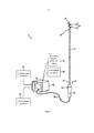
Фиг. 1 является отчасти схематической диаграммой системы нейромодуляции, сконструированной в соответствии с вариантом осуществления настоящего изобретения.FIG. 1 is partly a schematic diagram of a neuromodulation system constructed in accordance with an embodiment of the present invention.
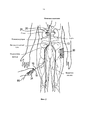
Фиг. 2 иллюстрирует модуляцию нервов почки с многоэлектродным катетером, сконструированным в соответствии с вариантом осуществления настоящего изобретения.FIG. 2 illustrates modulation of the nerves of a kidney with a multi-electrode catheter constructed in accordance with an embodiment of the present invention.
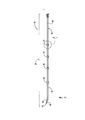
Фиг. 3А является видом сбоку дистальной части катетера, содержащей терапевтический блок или лечебную секцию в состоянии доставки (например, низкопрофильной или сжатой конфигурации) снаружи пациента, в соответствии с вариантом осуществления настоящего изобретения.FIG. 3A is a side view of a distal portion of a catheter containing a therapeutic unit or treatment section in a delivery state (e.g., low profile or compressed configuration) from outside a patient, in accordance with an embodiment of the present invention.
Фиг. 3В является изображением в перспективе дистальной части катетера с Фиг. 3А в развернутом состоянии (например, расширенной конфигурации) снаружи тела пациента.FIG. 3B is a perspective view of the distal portion of the catheter of FIG. 3A in an expanded state (for example, an expanded configuration) outside the patient’s body.
Фиг. 4 является увеличенным изображением части лечебного устройства с Фиг. 3А.FIG. 4 is an enlarged view of a portion of the treatment device of FIG. 3A.
Фиг. 5 является отчасти схематическим изображением загружающего устройства в соответствии с вариантом осуществления настоящего изобретения.FIG. 5 is a partially schematic illustration of a loading device in accordance with an embodiment of the present invention.
Фиг. 6 является концептуальной диаграммой, иллюстрирующей симпатическую нервную систему и то, как мозг сообщается с организмом через симпатическую нервную систему.FIG. 6 is a conceptual diagram illustrating the sympathetic nervous system and how the brain communicates with the body through the sympathetic nervous system.
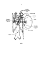
Фиг. 7 является увеличенным анатомическим изображением, иллюстрирующим нервы, иннервирующие левую почку, с формированием почечного сплетения, окружающего левую почечную артерию.FIG. 7 is an enlarged anatomical image illustrating the nerves innervating the left kidney, with the formation of the renal plexus surrounding the left renal artery.
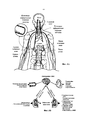
Фиг. 8А и 8В являются анатомическим и концептуальным изображением, соответственно, иллюстрирующим организм человека, включая головной мозг и почки, и нервное эфферентное и афферентное сообщение между головным мозгом и почками.FIG. 8A and 8B are anatomical and conceptual images, respectively, illustrating the human body, including the brain and kidneys, and the neural efferent and afferent communication between the brain and kidneys.
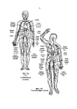
Фиг. 9А и 9В являются анатомическими изображениями, иллюстрирующими, соответственно, артериальную и венозную сосудистую сеть человека.FIG. 9A and 9B are anatomical images illustrating a human arterial and venous vasculature, respectively.
Подробное описание изобретенияDETAILED DESCRIPTION OF THE INVENTION
Настоящее изобретение направлено на устройства, системы и способы для достижения электрически и/или термически индуцированной нейромодуляции (т.е. обеспечения нейтрализации или инактивации, или иного полного или частичного снижения функции нервных волокон, иннервирующих почку) посредством чрескожного транслюминального внутрисосудистого доступа. В частности, варианты осуществления настоящего изобретения относятся к катетерам и блок катетеров, содержащим многоэлектродные матрицы, и обладающие возможностью перевода между состоянием доставки или низкопрофильным состоянием (например, в целом прямой формы) и развернутым состоянием (например, радиально расширенной, в целом спиральной формы). Электроды или элементы, доставляющие энергию, содержащие многоэлектродную матрицу, сконструированы для доставки энергии (например, электрической энергии, РЧ-энергии, импульсной электрической энергии, термической энергии) к почечной артерии после продвижения через катетер по чрескожному транслюминальному пути (например, через прокол в бедренной артерии, в подвздошную артерию и аорту, радиальную артерию, или по другому подходящему внутрисосудистому пути). Катетер или катетерный блок, несущий многоэлектродную матрицу, подобран по размеру и форме так, чтобы электроды или элементы, доставляющие энергию, контактировали с внутренней стенкой почечной артерии, когда катетер находится в развернутом (например, спиральном) состоянии в почечной артерии. Кроме того, спиральная форма развернутой части катетера, несущего матрицу, позволяет крови протекать через спираль, что, как ожидается, предотвращает окклюзию почечной артерии при активации элемента, доставляющего энергию. Далее, кровоток в матрице и вокруг нее может охлаждать связанные элементы, доставляющие энергию, обеспечивая доставку высоких уровней энергии при более низких температурах, чем те, которые могут быть достигнуты без охлаждения. Эта характеристика, как ожидается, способствует достижению более глубоких и/или обширных поражений при лечении, снижению температуры внутренней поверхности, и/или обеспечению более продолжительного времени активации при снижении риска избыточного нагревания во время лечения.The present invention is directed to devices, systems and methods for achieving electrically and / or thermally induced neuromodulation (i.e., ensuring neutralization or inactivation, or other complete or partial decrease in the function of nerve fibers that innervate the kidney) through percutaneous transluminal intravascular access. In particular, embodiments of the present invention relate to catheters and a catheter assembly containing multi-electrode arrays and having the ability to translate between a delivery state or a low profile state (e.g., a generally straight shape) and a deployed state (e.g., a radially expanded, generally spiral shape) . Electrodes or energy-supplying elements containing a multi-electrode matrix are designed to deliver energy (e.g., electrical energy, RF energy, pulsed electrical energy, thermal energy) to the renal artery after moving through a catheter along the percutaneous transluminal pathway (e.g., through a puncture in the femoral arteries, into the iliac artery and aorta, radial artery, or along another suitable intravascular pathway). A catheter or catheter block carrying a multi-electrode matrix is sized and shaped so that the electrodes or energy-delivering elements contact the inner wall of the renal artery when the catheter is in an unfolded (e.g., spiral) state in the renal artery. In addition, the spiral shape of the deployed portion of the catheter carrying the matrix allows blood to flow through the spiral, which is expected to prevent renal artery occlusion upon activation of the energy-delivering element. Further, blood flow in and around the matrix can cool related energy-delivering elements, delivering high levels of energy at lower temperatures than those that can be achieved without cooling. This characteristic is expected to contribute to achieving deeper and / or wider lesions during treatment, lowering the temperature of the inner surface, and / or providing a longer activation time while reducing the risk of excessive heat during treatment.
Специфические подробности некоторых вариантов осуществления изобретения описаны ниже со ссылкой на Фиг. 1-9В. Хотя многие из вариантов осуществления описаны ниже со ссылкой на устройства, системы способы для внутрисосудистой модуляции нервов с применением многоэлектродных матриц, другие приложения и другие варианты осуществления, в дополнение к тем, которые описаны в настоящей заявке, находятся в пределах объема настоящего изобретения. Кроме того, некоторые другие варианты осуществления изобретения могут иметь иные конфигурации, компоненты или процедуры, чем те, которые описаны в настоящей заявке. Таким образом, специалисту в данной области техники понятно, что изобретение может иметь другие варианты осуществления с дополнительными элементами, или изобретение может иметь другие варианты осуществления без некоторых характеристик, показанных и описанных ниже со ссылкой на Фиг. 1-9В.Specific details of some embodiments of the invention are described below with reference to FIG. 1-9V. Although many of the embodiments are described below with reference to devices, systems, methods for intravascular modulation of nerves using multi-electrode arrays, other applications and other embodiments, in addition to those described in this application, are within the scope of the present invention. In addition, some other embodiments of the invention may have other configurations, components or procedures than those described in this application. Thus, one skilled in the art will understand that the invention may have other embodiments with additional elements, or the invention may have other embodiments without some of the characteristics shown and described below with reference to FIG. 1-9V.
Термины «дистальный» и «проксимальный», используемые в настоящей заявке, определяют положение или направление по отношению к лечащему врачу или контрольному устройству врача (например, рукоятке в сборе). «Дистальный» или «дистально» может означать положение, удаленное, или находящееся в направлении от врача или контрольного устройства врача. «Проксимальный» или «проксимально» может означать положение рядом, или положение по направлению к врачу или контрольному устройству врача.The terms "distal" and "proximal" used in this application, determine the position or direction in relation to the attending physician or the control device of the doctor (for example, the handle assembly). “Distal” or “distal” may mean a position that is remote or away from the doctor or doctor’s control device. “Proximal” or “proximal” may mean a nearby position, or a position toward a doctor or doctor's monitoring device.
I. Нейромодуляция почекI. Neuromodulation of the kidneys
Нейромодуляция почек означает частичное или полное нарушение функции, или другое разрушение эффективности нервов, иннервирующих почки (например, обеспечение инертности или неактивности нервных волокон, или иное полное или частичное ослабление функции). Например, нейромодуляция почек может включать ингибирование, снижение и/или блокаду нервного сообщения по нервным волокнам (т.е. эфферентным и/или афферентным нервным волокнам), иннервирующим почки. Такое нарушение функции может быть долговременным (например, непрерывным в течение месяцев, лет или десятилетий) или кратковременным (например, в течение минут, часов, суток или недель). Предполагается, что нейромодуляция почек обеспечивает эффективное лечение некоторых патологических состояний, характеризующихся повышенной общей симпатической активностью, и в частности, состояний, связанных с центральной симпатической избыточной стимуляцией, таких как гипертензия, сердечная недостаточность, острый инфаркт миокарда, метаболический синдром, инсулиновая резистентность, диабет, гипертрофия левого желудочка, хроническая и терминальная почечная недостаточность, неадекватная задержка жидкости при сердечной недостаточности, кардио-ренальный синдром, остеопороз и внезапная смерть. Снижение афферентных нервных сигналов вносит вклад в системное снижение симпатического тонуса/стимула, а нейромодуляция почек, как ожидается, может быть полезной при лечении некоторых состояний, связанных с системной симпатической избыточной активностью или гиперактивностью. Нейромодуляция почек может быть полезной для различных органов и структур организма, иннервируемых симпатическими нервами.Renal neuromodulation means a partial or complete impairment of function, or another disruption of the effectiveness of the nerves innervating the kidneys (for example, ensuring inertness or inactivity of nerve fibers, or other complete or partial weakening of function). For example, renal neuromodulation may include inhibition, reduction, and / or blockage of nerve communication along nerve fibers (i.e., efferent and / or afferent nerve fibers) that innervate the kidneys. Such impaired function may be long-term (e.g., continuous for months, years, or decades) or short-term (e.g., minutes, hours, days, or weeks). It is assumed that renal neuromodulation provides effective treatment for certain pathological conditions characterized by increased general sympathetic activity, and in particular, conditions associated with central sympathetic excessive stimulation, such as hypertension, heart failure, acute myocardial infarction, metabolic syndrome, insulin resistance, diabetes, left ventricular hypertrophy, chronic and terminal renal failure, inadequate fluid retention in heart failure Nost, cardio-renal syndrome, osteoporosis, and sudden death. A decrease in afferent nerve signals contributes to a systemic decrease in sympathetic tone / stimulus, and neuromodulation of the kidneys is expected to be useful in the treatment of certain conditions associated with systemic sympathetic excess activity or hyperactivity. Renal neuromodulation may be beneficial for various organs and structures of the body innervated by sympathetic nerves.
Различные методики могут применяться для частичной или полной инактивации нервных путей, таких как те, которые иннервируют почку. Целенаправленное приложение энергии (например, электрической энергии, термической энергии) к ткани посредством элемента(ов), доставляющего энергию, может индуцировать один или несколько необходимых эффектов термического нагревания в локализованных участках почечной артерии и соседних участках почечного сплетения, прилегающих непосредственно или расположенных рядом с адвентициальной оболочкой почечной артерии. Целенаправленное приложение эффектов термического нагревания позволяет достичь нейромодуляции по всему почечному сплетению или его части.Various techniques can be used to partially or completely inactivate the neural pathways, such as those that innervate the kidney. The targeted application of energy (e.g., electrical energy, thermal energy) to the tissue through the energy delivery element (s) can induce one or more of the necessary effects of thermal heating in localized areas of the renal artery and adjacent areas of the renal plexus adjacent directly to or adjacent to the adventitia sheath of the renal artery. The purposeful application of the effects of thermal heating allows us to achieve neuromodulation throughout the renal plexus or part of it.
Термические эффекты могут включать как термическую абляцию, так и неабляционное термическое поражение или повреждение (например, посредством непрерывного нагревания и/или стойкого нагревания). Необходимые эффекты термического нагревания, например, могут включать повышение температуры целевых нервных волокон выше порога, необходимого для достижения неабляционного термического повреждения, или выше, до более высокой температуры, для достижения абляционного термического повреждения. Например, целевая температура может быть выше температуры тела (например, около 37°C), но ниже примерно 45°C, для неабляционного термического повреждения, или целевая температура может быть около 45°C или выше, для абляционного термического повреждения.Thermal effects can include both thermal ablation and non-ablative thermal damage or damage (for example, by continuous heating and / or persistent heating). The necessary effects of thermal heating, for example, may include raising the temperature of the target nerve fibers above the threshold necessary to achieve non-ablative thermal damage, or higher, to a higher temperature, to achieve ablative thermal damage. For example, the target temperature may be higher than body temperature (for example, about 37 ° C), but lower than about 45 ° C, for non-ablative thermal damage, or the target temperature may be about 45 ° C or higher, for ablative thermal damage.
В частности, воздействие термической энергии (нагревания), превышающей температуру тела около 37°C, но ниже температуры около 45°C, может индуцировать термическое повреждение посредством умеренного нагревания целевых нервных волокон или сосудистых структур, перфузирующих нервные волокна. В случаях, если повреждены сосудистые структуры, целевые нервные волокна могут быть лишены перфузии, что приводит к некрозу нервной ткани. Например, это может индуцировать неабляционное термическое повреждение волокон или структур. Воздействие нагревания выше температуры примерно 45°C, или выше примерно 60°C, может индуцировать термическую абляцию посредством существенного нагревания волокон или структур. Например, такие высокие температуры могут вызывать термическую абляцию целевых нервных волокон или сосудистых структур; у некоторых пациентов может быть необходимо достичь температур, вызывающих термическую абляцию целевых нервных волокон или сосудистых структур, но менее примерно 90°C, или менее примерно 85°C, или менее примерно 80°C, и/или менее примерно 75°C. Независимо от типа теплового воздействия, используемого для индукции термической нейромодуляции, ожидается снижение активности симпатических нервов в почках (АСНП).In particular, exposure to thermal energy (heating) above a body temperature of about 37 ° C but lower than a temperature of about 45 ° C can induce thermal damage by moderately heating target nerve fibers or vascular structures that perfuse nerve fibers. In cases where vascular structures are damaged, the target nerve fibers may be deprived of perfusion, which leads to necrosis of the nervous tissue. For example, this can induce non-ablative thermal damage to fibers or structures. Exposure to heating above a temperature of about 45 ° C, or above about 60 ° C, can induce thermal ablation by substantially heating the fibers or structures. For example, such high temperatures can cause thermal ablation of target nerve fibers or vascular structures; in some patients, it may be necessary to reach temperatures causing thermal ablation of the target nerve fibers or vascular structures, but less than about 90 ° C, or less than about 85 ° C, or less than about 80 ° C, and / or less than about 75 ° C. Regardless of the type of heat exposure used to induce thermal neuromodulation, a decrease in the activity of sympathetic nerves in the kidneys (ASNP) is expected.
II. Избранные варианты осуществления систем для нейромодуляцииII. Selected Embodiments of Systems for Neuromodulation
Фиг. 1 иллюстрирует систему для ренальной нейромодуляции 10 («систему 10»), сконструированную в соответствии с вариантом осуществления настоящего изобретения. Система 10 включает внутрисосудистый катетер 12, функционально связанный с источником энергии или генератором энергии 26 (например, генератором РЧ-энергии). Катетер 12 может включать удлиненный ствол 16, имеющий проксимальную часть 18, рукоятку 34 на проксимальном участке проксимальной части 18, и дистальную часть 20. Катетер 12 может дополнительно включать терапевтический блок или лечебную секцию 21 (показанную схематически) на дистальной части 20 (например, прикрепленную к дистальной части 20, определяющую секцию дистальной части 20, и т.д.). Как подробно разъясняется ниже, терапевтический блок 21 может включать поддерживающую структуру 22 и матрицу из двух или более элементов, доставляющих энергию 24 (например, электродов), сконструированных для доставки в кровеносный сосуд почки (например, почечную артерию) в низкопрофильной конфигурации. При доставке к целевому участку лечения в кровеносном сосуде почки, терапевтический блок 21 дополнительно сконструирован для развертывания в расширенное состояние (например, в целом спиральную/винтовую конфигурацию) для доставки энергии в участок лечения и обеспечения терапевтически эффективной электрически и/или термически индуцированной ренальной нейромодуляции. Альтернативно, развернутое состояние может быть не спиральным, с тем условием, что развернутое состояние доставляет энергию к участку лечения. Терапевтический блок 21 может быть трансформирован между состоянием доставки и развернутым состоянием с применением множества подходящих механизмов или методик (например, саморасширения, удаленной активации через привод, и т.д.).FIG. 1 illustrates a system for renal neuromodulation 10 (“
Проксимальный конец терапевтического блока 21 переносится или прикреплен к дистальной части 20 удлиненного ствола 16. Дистальный конец терапевтического блока 21 может заканчиваться катетером 12, например, с атравматическим наконечником 40. В некоторых вариантах осуществления дистальный конец терапевтического блока 21 может также быть сконструирован для сцепления с другим элементом системы 10 или катетера 12. Например, дистальный конец терапевтического блока 21 может определять проход для приема проволочного направляющего элемента (не показанного) для доставки лечебного устройства с применением методик доставки по проводнику («OTW») или быстрого обмена («RX»). Дополнительные подробности, касающиеся таких размещений, описаны ниже.The proximal end of the
Катетер 12 может быть электрически соединен с источником энергии 26 через кабель 28, и источник энергии 26 (например, генератор РЧ-энергии) может быть сконструирован для получения избранной модальности и амплитуды энергии для доставки к участку лечения посредством элементов, доставляющих энергию 24. Как подробно описано ниже, подающие провода (не показаны) могут проходить вдоль удлиненного ствола 16 или через полость в стволе 16 к отдельным элементам, доставляющим энергию 24, и передавать лечебную энергию к элементам, доставляющим энергию 24. В некоторых вариантах осуществления каждый элемент, доставляющий энергию 24, включает собственный подающий провод. Однако в других вариантах осуществления два или более элемента, доставляющих энергию 24, могут быть электрически связаны с тем же самым подающим проводом. Контрольный механизм 32, такой как ножная педаль или переносное удаленное контрольное устройство, может быть соединен с источником энергии 26, чтобы позволить врачу начинать, заканчивать, и факультативно, регулировать различные оперативные характеристики источника энергии 26, включая доставку энергии, но не ограничиваясь ею. Устройство удаленного контроля (не показано) может располагаться в стерильной области, функционально соединяться с элементами, доставляющими энергию 24, и может быть сконструировано, чтобы позволить врачу избирательно активировать и дезактивировать элементы, доставляющие энергию 24. В других вариантах осуществления устройство удаленного контроля может быть встроено в рукоятку в сборе 34.The
Источник энергии или генератор энергии 26 может быть сконструирован для доставки лечебной энергии посредством автоматизированного контрольного алгоритма 30 и/или под контролем врача. Например, источник энергии 26 может включать компьютерные устройства (например, персональные компьютеры, служебные ЭВМ, планшеты, и т.д.), имеющие обрабатывающую схему (например, микропроцессор), сконструированный для выполнения хранящихся инструкций, связанных с контрольным алгоритмом 30. Кроме того, обрабатывающая схема может быть сконструирована для выполнения одного или нескольких алгоритмов оценки/обратной связи 31, которые могут сообщаться с врачом. Например, источник энергии 26 может включать монитор или дисплей 33 и/или связанные характеристики, сконструированные для обеспечения визуальных, аудио, или иных указаний уровня мощности, показаний датчиков, и/или иной обратной связи. Источник энергии 26 может также быть сконструирован для передачи обратной связи и другой информации к другому устройству, такому как монитор в лаборатории катетеризации.An energy source or
Элементы, доставляющие энергию 24, могут быть сконструированы для доставки энергии независимо (т.е. могут применяться в однополярном режиме), одновременно, избирательно, или последовательно, и/или могут доставлять энергию между любой необходимой комбинацией элементов (т.е. могут применяться в биполярном режиме). В однополярных вариантах осуществления нейтральный или дисперсионный электрод 38 может электрически соединяться с генератором энергии 26, и присоединяться к внешней области пациента (например, как показано на Фиг. 2). Далее, врач факультативно может выбрать, какой элемент(ы), доставляющий энергию 24, применять для доставки энергии с целью формирования высоко специфического поражения(ний) в почечной артерии, имеющей разнообразные формы или виды. В других вариантах осуществления система 10 может быть сконструирована для доставки других подходящих форм лечебной энергии, таких как комбинация однополярных и биполярных электрических полей.
В некоторых вариантах осуществления источник энергии 26 может включать модуль оценки радиочастотной идентификации (РЧИД) (не показан), установленный на одном или нескольких портах на источнике энергии 26 или рядом с ними, и сконструированный для беспроводного чтения и записи одного или нескольких РЧИД наконечников (не показаны) на катетере 12. В одном частном варианте осуществления, например, катетер 12 может включать РЧИД наконечник, расположенный внутри или иным образом прикрепленный к соединительной части кабеля 28, связанного с источником энергии 26. РЧИД наконечник может включать, например, антенну и РЧИД чип для обработки сигналов, отправки/приема РЧ- сигналов, и хранения данных в памяти. Подходящие РЧИД наконечники включают, например, РЧИД наконечники MB89R118, поставляемые Fujitsu Limited, Токио, Япония. Запоминающая часть РЧИД наконечника может включать множество блоков, назначенных для различных типов данных. Например, первый блок памяти может включать идентификатор валидации (например, уникальный идентификатор, связанный со специфическим типом катетера и генерируемый от уникального идентификационного номера РЧИД наконечника с применением алгоритма шифровки), а второй блок памяти может быть предназначен в качестве счетчика использования катетера, который может читаться, а затем записываться РЧИД модулем, переносимым источником энергии 26 после применения катетера. В других вариантах осуществления РЧИД наконечник может включать дополнительные блоки памяти, назначенные для дополнительных счетчиков применения катетера (например, для обеспечения применения катетера 12 специфическое ограниченное число раз) и/или другой информации, связанной с катетером 12 (например, номера серии, номера абонента, модели катетера, общих данных, и т.д.).In some embodiments, the implementation of the
Модуль оценки РЧИД, переносимый источником энергии 26, может включать антенну и контур обработки, которые совместно применяются для сообщения с одной или несколькими частями источника энергии 26 и беспроводного чтения/записи одного или нескольких РЧИД наконечников поблизости от них (например, когда кабель 28, включающий РЧИД наконечник, присоединен к источнику энергии 26). Подходящие модели РЧИД оценки включают, например, TRF796QA модуль оценки, поставляемый Texas Instruments Incorporated, Даллас, Техас.The RFID estimation module carried by the
При функционировании РЧИД модуль оценки сконструирован для чтения информации от РЧИД наконечника (переносимого кабелем 28 или другой подходящей частью катетера 12), и передачи информации программному обеспечению источника энергии 26 для валидации присоединенного катетера 12 (например, оценки совместимости катетера 12 с источником энергии 26), чтения числа предыдущих применений, связанных с конкретным катетером 12, и/или записи РЧИД наконечника для индикации применения катетера. В различных вариантах осуществления источник энергии 26 может быть сконструирован для блокирования доставки энергии к катетеру 12, если предварительно заданные условия РЧИД наконечника не выполняются. Например, когда каждый катетер 12 соединяется с источником энергии 26, РЧИД модуль оценки может читать уникальный антифальсификационный номер в зашифрованном формате с РЧИД наконечника, расшифровывать номер, а затем удостоверять номер и формат данных катетера для распознанных катетеров (например, катетеров, совместимых с конкретным источником энергии 26, не фальсифицированных катетеров, и т.д.). В различных вариантах осуществления РЧИД наконечник может включать идентификаторы, которые соответствуют специфическому типу катетера, и РЧИД модуль оценки может передавать эту информацию главному контроллеру источника энергию 26, который может регулировать установки (например, контрольный алгоритм 30) источника энергии 26 до необходимых операционных параметров/характеристик (например, уровней мощности, режимов отображения, и т.д.), связанных со специфическим катетером. Далее, если РЧИД модуль оценки идентифицирует катетер 12 как фальсифицированный, или по иным причинам не может идентифицировать катетер 12, источник энергии 26 может автоматически блокировать применение катетера 12 (например, предотвращать доставку энергии).In operation, the RFID evaluation module is designed to read information from the RFID tip (carried by
Когда катетер 12 идентифицирован, модуль оценки РЧИД может читать адрес ячейки памяти РЧИД наконечника, чтобы определить, был ли катетер 12 раньше соединен с генератором (т.е. использовался ранее). В некоторых вариантах осуществления РЧИД наконечник может ограничивать катетер 12 до единичного применения, но в других вариантах осуществления РЧИД наконечник может быть сконструирован для обеспечения более одного применения (например, 2 применений, 5 применений, 10 применений, и т.д.). Если модуль оценки РЧИД распознает, что катетер 12 был записан (т.е. применялся) более предварительно заданного предела применения, то РЧИД модуль может передавать сообщение источнику энергии 26 для блокирования доставки энергии к катетеру 12. В некоторых вариантах осуществления модуль оценки РЧИД может быть сконструирован для интерпретации всех соединений катетера с источником энергии в течение предварительно заданного периода времени (например, 5 часов, 10 часов, 24 часов, 30 часов и т.д.) в качестве единственного соединения (т.е. единственного применения), и обеспечения использования катетера 12 множество раз в течение предварительно заданного периода времени. После обнаружения, распознавания и оценки катетера 12 в качестве «нового соединения» (например, не используемого более предварительно заданного предела), модуль оценки РЧИД может делать запись на РЧИД наконечнике (например, время и дату применения системы и/или другую информацию) для индикации применения катетера 12. В других вариантах осуществления модуль оценки РЧИД и/или РЧИД наконечник могут иметь другие характеристики и/или другие конфигурации.Once the
Система 10 может также включать один или несколько датчиков (не показанных), расположенных поблизости или внутри элементов, доставляющих энергию 24. Например, система 10 может включать датчики температуры (например, термопары, термисторы и т.д.), датчики импеданса, датчики давления, оптические датчики, датчики потока, и/или другие подходящие датчики, соединенные с одним или несколькими подающими проводами (не показаны), передающими сигналы от датчиков и/или подающими энергию к элементам, доставляющим энергию 24. Фиг. 2 (с дополнительной ссылкой на Фиг. 1) иллюстрирует модуляцию нервов почки с вариантом осуществления системы 10. Катетер 12 обеспечивает доступ к почечному сплетению ПС через внутрисосудистый путь П, такой как от чрескожного участка доступа в бедренной (показано), плечевой, лучевой или подмышечной артерии к целевому участку лечения в соответствующей почечной артерии ПА. Как иллюстрировано, секция проксимальной части 18 ствола 16 расположена снаружи пациента. Путем манипуляции проксимальной частью 18 ствола 16 с наружной стороны внутрисосудистого пути П, врач может продвигать ствол 16 через отчасти извилистый внутрисосудистый путь П, и осуществлять удаленную манипуляцию дистальной частью 20 ствола 16. В варианте осуществления, иллюстрированном на Фиг. 2, терапевтический блок 21 доставляют интраваскулярно к участку лечения с применением проволочного направляющего элемента 66 по методике OTW. Как упоминалось ранее, дистальный конец терапевтического блока 21 может определять полость или проход для приема проволочного направляющего элемента 66 для доставки катетера 12 с применением методик OTW или RX. В участке лечения проволочный направляющий элемент 66 может быть по меньшей мере частично аксиально извлечен или удален, и терапевтический блок 21 может быть трансформирован или иным образом перемещен в развернутое состояние для доставки энергии к участку лечения. Дополнительные подробности, касающиеся таких размещений, описаны ниже со ссылкой на Фиг. 3А и 3В. Проволочный направляющий элемент 66 может включать любой подходящий медицинский проволочный направляющий элемент, подобранный по размеру для установки при скольжении внутри полости. В одном частном варианте осуществления, например, проволочный направляющий элемент 66 может иметь диаметр 0,365 мм (0,014 дюймов). В других вариантах осуществления терапевтический блок 21 может быть доставлен к участку лечения внутри направляющей капсулы (не показанной) с применением проволочного направляющего элемента 66 или без него. Когда терапевтический блок 21 находится в участке лечения, направляющая капсула может быть по меньшей мере частично извлечена или втянута, а терапевтический блок 21 может быть трансформирован в развернутое состояние. Дополнительные подробности, касающиеся этого типа конфигурации, описаны ниже. В других вариантах осуществления ствол 16 может быть управляемым, так чтобы терапевтический блок 21 можно было доставлять к участку лечения без применения проволочного направляющего элемента 66 и/или направляющей капсулы.
Управление с визуализацией, например, компьютерную томографию (КТ), флюороскопию, внутрисосудистый ультразвук (ВСУЗ), оптическую когерентную томографию (ОКТ), интракардиальную эхокардиографию (ИКЭ), или другую подходящую методику управления, или их комбинации, можно применять для расположения и манипуляции врачом терапевтического блока 21. Например, флюороскопическую систему (например, включающую плоскопанельный детектор, рентген или раму С-типа) можно вращать для точной визуализации и идентификации целевого участка лечения. В других вариантах осуществления участок лечения может быть определен с применением ВСУЗ, ОКТ и/или других подходящих методик визуализации, которые могут сопоставлять целевой участок лечения с идентифицируемой анатомической структурой (например, спинальной характеристикой) и/или радионепроницаемой линейкой (например, расположенной под пациентом или на нем) перед доставкой катетера 12. Далее, в некоторых вариантах осуществления компоненты управления с визуализацией (например, ВСУЗ, ОКТ) могут быть интегрированы с катетером 12 и/или работать параллельно с катетером 12 для обеспечения управления с визуализацией во время размещения терапевтического блока 21. Например, компоненты управления с визуализацией (например, ВСУЗ или ОКТ) могут быть соединены по меньшей мере с одним из терапевтического блока 21 (например, проксимально к терапевтическим штативам 25) для обеспечения трехмерных изображений сосудистой сети рядом с участком лечения, для облегчения размещения или развертывания многоэлектродного блока в целевом кровеносном сосуде почки.Imaging management, such as computed tomography (CT), fluoroscopy, intravascular ultrasound (IVSC), optical coherence tomography (OCT), intracardial echocardiography (IEC), or other suitable management technique, or combinations thereof, can be used to locate and manipulate the physician
Целенаправленное приложение энергии от элементов, доставляющих энергию 24, может затем применяться к целевой ткани для индукции одного или нескольких необходимых нейромодулирующих эффектов в локализованных участках почечной артерии и соседних участках почечного сплетения ПС, которые находятся непосредственно в адвентициальной оболочке почечной артерии А, рядом, или в тесной близости к ней. Целенаправленное приложение энергии может обеспечивать нейромодуляцию по всему почечному сплетению ПС или его части. Нейромодулирующие эффекты, как правило, являются функцией, по меньшей мере отчасти, мощности, времени, контакта между элементами, доставляющими энергию 24 (Фиг. 1) и стенкой сосуда, и кровотока через сосуд. Нейромодулирующие эффекты могут включать денервацию, термическую абляцию, и/или неабляционное термическое повреждение или нарушение (например, посредством непрерывного нагревания и/или резистивного нагревания). Необходимые эффекты термического нагревания могут включать повышение температуры целевых нервных волокон выше необходимого порога для достижения неабляционного термического повреждения, или более высокой температуры для достижения абляционного термического повреждения. Например, целевая температура может быть выше температуры тела (например, около 37°C), но менее примерно 45°C для неабляционного термического повреждения, или целевая температура может составлять примерно 45°С или выше для абляционного термического повреждения. Необходимые нетермические нейромодулирующие эффекты могут включать изменение электрических сигналов, передаваемых в нерве.The targeted application of energy from the
Фиг. 3А является видом сбоку дистальной части 20 катетера 12 и терапевтического блока или лечебной секции 21 в развернутом состоянии (например, низкопрофильной или сжатой конфигурации) снаружи пациента, а Фиг. 3В является изображением в перспективе терапевтического блока 21 в развернутом состоянии (например, расширенной конфигурации) снаружи пациента. Как было описано ранее, катетер 12 может быть сконструирован для OTW доставки от участка доступа, в котором проволочный направляющий элемент 66 (Фиг. 2) вначале вводят в участок лечения (например, внутри почечной артерии), а катетер 12 вставляют по проволочному направляющему элементу. Как более подробно описано ниже, проволочный направляющий элемент может быть введен или по меньшей частично извлечен из дистальной части 20 для трансформации терапевтического блока 21 между состоянием доставки (Фиг. 3А) и развернутым состоянием (Фиг. 3В). Например, как показано на Фиг. 3А, проволочный направляющий элемент (не показан), проходящий по меньшей мере через часть длины катетера 12, может быть сконструирован для распрямления спирального винтового контрольного элемента 50 с предварительно заданной формой (схематически показанного штриховыми линиями) из катетера 12 во время доставки; а проволочный направляющий элемент по меньшей мере частично извлечен или перемещен при скольжении относительно дистальной части 20, для обеспечения трансформации терапевтического блока 21 в развернутое состояние (Фиг. 3В).FIG. 3A is a side view of the
Как лучше видно на Фиг. 3А, терапевтический блок 21 включает множество (например, четыре, пять, и т.д.) элементов, доставляющих энергию 24, переносимых поддерживающей структурой 22. В этом варианте осуществления поддерживающая структура 22 содержит гибкую трубку 42 и контрольный элемент 50 с предварительно заданной формой внутри трубки 42. Гибкая трубка 42 может состоять из полимерного материала, такого как полиамид, полиимид, полиэфир-блок-амидный сополимер, поставляемый под торговой маркой Пебакс, полиэтилен терефталат (ПЭТ), полипропилен; алифатический термопластический полиуретан на поликарбонатной основе, поставляемый под торговой маркой Карботан; или полиэфирэфиркетоновый (ПЭЭК) полимер, обеспечивающий необходимую гибкость. Однако в других вариантах осуществления трубка 42 может состоять из других подходящих материалов.As best seen in FIG. 3A, the
Как упоминалось выше, контрольный элемент 50 с предварительно заданной формой может использоваться для обеспечения спиральной/винтовой формы относительно гибкой дистальной части 20 катетера 12. Как лучше видно на Фиг. 3, например, контрольный элемент 50 является трубчатой структурой, содержащей нитиноловую мультифиламентную скрученную проволоку с полостью в ней, и поставляемую под торговой маркой HELICAL HOLLOW STRAND (HHS) от Fort Wayne Metals, Форт-Уэйн, Индиана. Трубчатый контрольный элемент 50 может быть сформирован из множества различных типов материалов, может быть расположен в одинарной или двухслойной конфигурации, и может быть произведен с выбранным направлением растяжения, сжатия, вращения и резьбы. Например, материал HHS может быть обрезан с применением лазера, электроискровой обработки (ЭИО), электрохимического шлифования (ЭХШ), или других подходящих средств для достижения необходимой итоговой длины и геометрии компонента. Например, как лучше видно на Фиг. 3В, контрольный элемент 50 в варианте настоящего изобретения имеет предварительно заданную спиральную/винтовую конфигурацию, определяющую развернутое состояние терапевтического блока 21, так чтобы элементы, доставляющие энергию 24 из терапевтического блока 21, были смещены друг от друга (например, оба смещены в угловом и продольном направлении относительно продольной оси почечной артерии), и могли располагаться в устойчивом контакте со стенкой почечной артерии (Фиг. 2) для лечения. Для простоты, предварительно заданная спиральная форма терапевтического блока 21 в развернутом состоянии может быть определена размерами (например, спиральным диаметром и шагом резьбы) самого HHS. Другими словами, мультифиламентная полая трубка, образующая контрольный элемент 50, сама имеет предварительно заданную спиральную форму.As mentioned above, a predefined
Формирование контрольного элемента 50 нитиноловой мультифиламентной скрученной проволоки (проволок) или других подобных материалов, как ожидалось, устранит необходимость какой-либо дополнительной армированной проволоки (проволок) или структур внутри поддерживающей структуры 22 для обеспечения необходимого уровня поддержки и жесткости терапевтического блока 21. Эта характеристика, как ожидается, снижает число производственных процессов, необходимых для формирования катетера 12, и уменьшает число материалов, необходимых для устройства. Другой характеристикой терапевтического блока 12 является то, что контрольный элемент 50 и внутренняя стенка трубки 42 находятся в тесном контакте, и имеется мало, или не имеется пространства между контрольным элементом 50 и трубкой 42 (как лучше видно на Фиг. 4). В одном варианте осуществления, например, трубка 42 может быть расширена перед сборкой, так что применение горячего воздуха к трубке 42 во время производственного процесса может вызывать усадку трубки на контрольный элемент 50, как понятно знакомым с обычным применением материалов для трубок из термоусадочной пленки. Эта характеристика, как ожидается, подавляет или устраняет складки или перегибы, которые могут возникать на трубке 42, когда терапевтический блок 21 трансформируется из относительно прямого состояния доставки до развернутого, в целом спирального состояния.The formation of the
В других вариантах осуществления контрольный элемент 50 и/или другие компоненты поддерживающей структуры 22 могут состоять из различных материалов и/или иметь другое размещение. Например, контрольный элемент 50 может быть сформирован из других подходящих материалов с памятью формы (например, никеля-титана (нитинола), проволоки или трубки, помимо HHS; полимеров с памятью формы, электроактивных полимеров), предварительно сформированных или с предварительно заданной формой в необходимом развернутом состоянии. Альтернативно, контрольный элемент 50 может быть сформирован из множества материалов, таких как композиция из одного или нескольких полимеров и металлов.In other embodiments, the implementation of the
Матрица из элементов, доставляющих энергию 24, может включать серии из отдельных ленточных электродов, размещенных вдоль поддерживающей структуры 22 и связанных с трубкой 42 с применением адгезивного средства. Ленточные или трубчатые электроды могут применяться в некоторых вариантах осуществления, например, поскольку они, как правило, имеют более низкие энергетические потребности для абляции, по сравнению с дисковыми или плоскими электродами. Однако в других вариантах осуществления также пригодны дисковые или плоские электроды. В еще одном варианте осуществления могут применяться электроды, имеющие спиральную или винтовую форму. В некоторых вариантах осуществления элементы, доставляющие энергию 24, могут быть равномерно разделены по длине поддерживающей структуры 22. Элементы, доставляющие энергию 24, могут быть изготовлены из любого подходящего металлического материала (например, золота, платины, или сплава платины и иридия, и т.д.). Однако в других вариантах осуществления число, расположение и/или состав элементов, доставляющих энергию 24, может варьировать.The matrix of
Фиг. 4 является увеличенным изображением части катетера 12 с Фиг. 3А. Что касается Фиг. 1 и 4 вместе, каждый элемент, доставляющий энергию, или электрод 24, электрически соединяется с источником энергии 26 (Фиг. 1) посредством проводника или бифилярного провода 44, проходящего через полость трубки 42. Каждый элемент, доставляющий энергию 24, может быть приварен или иным образом соединен с проводом, подающим энергию 44, а каждый провод 44 может проходить через трубку 42 и удлиненный ствол 16 (Фиг. 1) по всей длине ствола, так чтобы его проксимальный конец был связан с источником энергии 26 (Фиг. 1). Как упоминалось выше, трубка 42 сконструирована для тесной подгонки к контрольному элементу 50 и проводам 44, для минимизации расстояния между внутренней частью трубки 42 и компонентами, расположенными в ней, для предотвращения формирования складок в терапевтическом блоке 21 при развертывании. В некоторых вариантах осуществления катетер 12 может также включать изолирующий слой (например, слой ПЭТ или другого подходящего материала) поверх контрольного элемента 50 для дополнительной электрической изоляции материала (например, HHS) контрольного элемента 50 от проводов 44.FIG. 4 is an enlarged view of a portion of the
Как лучше видно на Фиг. 4, каждый элемент, доставляющий энергию 24, может включать суженные концевые части 24а (например, округления), сконструированные для обеспечения тупого угла между внешней поверхностью трубки 42 и внешней поверхностью соответствующего элемента, доставляющего энергию 24. Гладкий переход угла, обеспеченный суженными концевыми частями 24а, как ожидается, предотвращает заедание или захват направляющей капсулы или загружающего инструмента краями элементов, доставляющих энергию 24, когда направляющая капсула или загружающий элемент продвигается по длине терапевтического блока 21 (Фиг. 3А и 3В) при продвижении и извлечении. В других вариантах осуществления протяженность суженных частей 24а на элементах, доставляющих энергию 24, может варьировать. В некоторых вариантах осуществления суженные концевые части 24 содержат округления, сформированные из адгезивного материала на каждом конце соответствующих элементов, доставляющих энергию 24. В других вариантах осуществления, однако, суженные концевые части 24а могут быть выполнены из того же самого материала, что и трубка 42 (например, сформированы как единое целое с трубкой 42, или сформированы отдельно и прикреплены к любому концу элемента, доставляющего энергию 24). Далее, суженные части 24а являются факультативной характеристикой, которая может быть не включена в некоторых вариантах осуществления.As best seen in FIG. 4, each
Возвращаясь к Фиг. 3А и 3В, терапевтический блок 21 включает атравматический гибкий изогнутый наконечник 40 на дистальном конце блока 21. Изогнутый наконечник 40 сконструирован для обеспечения дистального отверстия 41 для проволочного направляющего элемента 66 (Фиг. 2), который отводит проволочный направляющий элемент от стенки почечной артерии, когда терапевтический блок 21 находится в предварительно заданной развернутой конфигурации. Ожидается, что эта характеристика облегчает выравнивание спирального терапевтического блока 21 в кровеносном сосуде, когда он расширяется, а также снижает риск повреждения стенки кровеносного сосуда, когда дистальный наконечник проволочного направляющего элемента продвигают из отверстия 41. Кривизна наконечника 40 может варьировать, в зависимости от конкретного размера/конфигурации терапевтического блока 21. Как лучше видно на Фиг. 3В, например, в иллюстрированном варианте осуществления наконечник 40 является изогнутым, так что он находится вне предварительно заданной спиральной/винтовой оси, определенной контрольным элементом 50. Однако в других вариантах осуществления наконечник 40 может иметь другую кривизну. В некоторых вариантах осуществления наконечник 40 может также включать один или несколько радионепроницаемых маркеров 52 и/или один или несколько датчиков (не показаны). Наконечник 40 может быть прикреплен к дистальному концу поддерживающей структуры 22 с помощью адгезивного средства, опрессовки, многокомпонентного формования, или других подходящих методик.Returning to FIG. 3A and 3B, the
Гибкий изогнутый наконечник 40 может быть изготовлен из полимерного материала (например, полиэфир-блокамидного сополимера, поставляемого под торговой маркой Пебакс), термопластического полиэфируретанового материала (поставляемого под торговыми марками Эластан или Пеллетан), или других подходящих материалов, имеющих необходимые свойства, включая выбранную твердость. Как упоминалось выше, наконечник 40 сконструирован для обеспечения отверстия для проволочного направляющего элемента 66, и необходимо, чтобы сам наконечник сохранял необходимую форму/конфигурацию при операции. Соответственно, в некоторых вариантах осуществления могут быть добавлены один или несколько материалов наконечника, чтобы способствовать улучшению сохранения формы наконечника, например, в одном варианте осуществления примерно 5-30 масс. % силоксана может быть смешано с материалом наконечника (например, термопластическим полиэфируретановым материалом), и можно применять электронный пучок или гамма-облучение для индукции поперечной сшивки материалов. В других вариантах осуществления наконечник 40 может быть сформирован из другого материала (материалов) и/или иметь другое расположение.The flexible
При операции (и со ссылкой на Фиг. 2, 3А и 3В), после размещения терапевтического блока 21 в необходимом участке в почечной артерии ПА пациента, терапевтический блок 21 может быть трансформирован из его состояния доставки в его развернутое состояние или развернутое расположение. Трансформация может быть начата с применением размещения компонентов устройства, как описано в настоящей заявке по отношению к частным вариантам осуществления и их различным режимам развертывания. В одном варианте осуществления, например, терапевтический блок 21 может быть развернут путем втягивания проволочного направляющего элемента 66, пока дистальный наконечник проволочного направляющего элемента 66 не будет в целом выровнен с наконечником 40 катетера 12. В некоторых вариантах осуществления проволочный направляющий элемент 66 может иметь различную жесткость или гибкость по своей длине, так чтобы обеспечить повышенную гибкость в дистальном направлении. Когда проволочный направляющий элемент 66 с вариабельной гибкостью частично втянут, как описано выше, предварительно установленная спиральная форма контрольного элемента 50 обеспечивает усилие, восстанавливающее форму, достаточное для преодоления распрямляющего усилия, обеспеченного наиболее дистальной частью проволочного направляющего элемента 66, так что терапевтический блок 21 может развертываться в спиральную конфигурацию. Далее, поскольку гибкая дистальная часть проволочного направляющего элемента 66 остается внутри терапевтического блока 21 в развернутом состоянии, проволочный направляющий элемент 66 может обеспечивать дополнительную структурную целостность спиральной части при лечении. Эта характеристика, как ожидается, способствует миграции или снижает проблемы, связанные с сохранением терапевтического блока на месте во время лечения (например, способствует вазоконстрикции).During surgery (and with reference to Figs. 2, 3A and 3B), after the
В другом варианте осуществления проволочный направляющий элемент 66 может иметь профиль жесткости, позволяющий дистальной части проволочного направляющего элемента 66 оставаться выступающей из отверстия 41, при этом позволяя терапевтическому блоку 21 трансформироваться до его развернутой конфигурации. В других вариантах осуществления проволочный направляющий элемент 66 может быть полностью извлечен из терапевтического блока 21 (например, наиболее дистальная концевая часть проволочного направляющего элемента 66 является проксимальной для терапевтического блока 21) для обеспечения трансформации, в то время как самая дистальная часть проволочного направляющего элемента 66 остается внутри ствола 16. В другом варианте осуществления проволочный направляющий элемент 66 может быть полностью извлечен из ствола 16. В любом из вышеизложенных примеров врач может извлекать проволочный направляющий элемент 66 в достаточной степени для наблюдения терапевтического блока в развернутой конфигурации, и/или пока рентгеновское изображение не покажет, что дистальный наконечник проволочного направляющего элемента 66 находится в необходимом участке по отношению к терапевтическому блоку 21 (например, в целом выровнен с наконечником 40, полностью извлечен из терапевтического блока 21 и т.д.). В некоторых вариантах осуществления степень извлечения проволочного направляющего элемента может быть основана, по меньшей мере отчасти, на решении врача по отношению к выбранному проволочному направляющему элементу и степени извлечения, необходимой для достижения развертывания.In another embodiment, the
После лечения терапевтический блок 21 может быть трансформирован назад в низкопрофильную конфигурацию доставки путем аксиального продвижения проволочного направляющего элемента 66 относительно терапевтического блока 21. Например, в одном варианте осуществления проволочный направляющий элемент 66 может продвигаться до тех пор, пока дистальный наконечник проволочного направляющего элемента 66 не будет в целом выровнен с наконечником 40, и катетер 12 может затем быть вытянут назад над стационарным проволочным направляющим элементом 66. Однако в других вариантах осуществления наиболее дистальная часть проволочного направляющего элемента 66 может продвигаться к другому участку относительно терапевтического блока 21, для достижения трансформации терапевтического блока 21 назад в низкопрофильную конфигурацию.After treatment, the
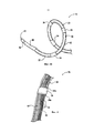
Варианты осуществления катетерной системы, описанные выше, включают процедурный проволочный направляющий элемент для направления катетера к участку лечения, а также для ограничения терапевтического блока или лечебной секции в низкопрофильной конфигурации доставки. В других вариантах осуществления катетерные системы, сконструированные в соответствии с настоящей технологией, могут дополнительно включать внешний загружающий инструмент, который может располагаться и втягиваться поверх терапевтического блока для дополнительного содействия трансформации терапевтического блока между конфигурацией доставки и развернутой конфигурацией.Embodiments of the catheter system described above include a procedural guide wire for guiding the catheter to the treatment site, as well as limiting the therapeutic block or treatment section in a low-profile delivery configuration. In other embodiments, catheter systems constructed in accordance with the present technology may further include an external loading tool that can be positioned and retracted over the therapeutic block to further facilitate the transformation of the therapeutic block between the delivery configuration and the deployed configuration.
Например, Фиг. 5 является отчасти схематическим видом сбоку загружающего инструмента 190 в соответствии с вариантом осуществления настоящего изобретения. Загружающий инструмент 190 является трубчатой структурой, сконструированной для передвижения при скольжении по внешней поверхности ствола 16 и терапевтического блока 21 (с целью иллюстрации, терапевтический блок 21 и связанные характеристики показаны штриховыми линиями). Загружающий инструмент 190 имеет размер и жесткость, пригодные для сохранения терапевтического блока 21 в низкопрофильной конфигурации для обратной загрузки проволочного направляющего элемента 66 (Фиг. 2), т.е. вставки проксимального конца проволочного направляющего элемента 66 в дистальное отверстие 41. В иллюстрированном варианте осуществления загружающий инструмент 190 может включать суженную часть 192, чтобы облегчать продвижение оболочки поверх терапевтического блока 21 и связанных элементов, доставляющих энергию 24. В некоторых вариантах осуществления дистальная часть 194 загружающего инструмента 190 может также включать гладкие, округленные внутренние и внешние края 195, чтобы способствовать ослаблению внутренней стенки загружающего инструмента поверх элементов, доставляющих энергию 24, при продвижении загружающего инструмента относительно терапевтического блока 21. Загружающий элемент 190 может состоять из полиэтилена высокой плотности (ПЭВП) или других подходящих материалов, имеющих необходимую прочность и скользкость. В других вариантах осуществления загружающий инструмент 190 может состоять из двух или более различных материалов. В одном варианте осуществления, например, секция наибольшего диаметра загружающего инструмента 190 дистально от суженной части 192 может состоять из ПЭВП, в то время как секция наименьшего диаметра загружающего инструмента 190 проксимально от суженной части 192 может состоять из линейного полиэтилена низкой плотности ЛПЭНП). В других вариантах осуществления загружающий инструмент 190 может состоять из различных материалов и/или иметь иную конфигурацию.For example, FIG. 5 is a partially schematic side view of a
В других вариантах осуществления загружающий инструмент 190 может быть пригоден в сочетании с катетером 12, когда катетер 12 находится вне пациента перед лечением, а затем удаляется из катетера 12 перед введением катетера 12 пациенту. В частности, как обсуждалось выше, загружающий инструмент 190 можно использовать для сохранения терапевтического блока 21 в низкопрофильной конфигурации, когда проволочный направляющий элемент загружают назад (передвигают от дистального конца к проксимальному концу катетера 12). Загружающий инструмент 190 затем может быть удален из катетера 12, а терапевтический блок 21 может быть ограничен в конфигурации доставки с поддержкой проволочного направляющего элемента; в другом варианте осуществления загружающий инструмент 190 может оставаться установленным на катетер 12 после обратной загрузки проволочного направляющего элемента, но может скользить по длине катетера 12 к проксимальной части 18 катетера 12 рядом с рукояткой 34 (Фиг. 1). таким образом, загружающий инструмент 190 остается с катетером 12, но удаляется во время лечения.In other embodiments, the
Однако в других вариантах осуществления загрузочный инструмент 190 может оставаться на дистальной части 20 (Фиг. 1) катетера 12 или рядом с ней во время лечения. Например, в одном варианте осуществления врач может удерживать загрузочный инструмент 190 на дистальной части 20 катетера 12 или рядом с ней, а затем вставлять загружающий инструмент 190 в гемостатический клапан (не показан), соединенный с направляющим катетером (не показан). В зависимости от профиля загружающего инструмента 190 и внутреннего диаметра гемостатического клапана, врач может вставить примерно 2-4 см загружающего инструмента 190 в гемостатический клапан. Одним преимуществом такого подхода является то, что терапевтический блок 21 (Фиг. 3А и 3В) дополнительно защищен, когда катетер 12 продвигают через гемостатический клапан, и врач, как ожидается, будет чувствовать меньше, или не чувствовать совсем трения между катетером 12 и гемостатическим клапаном. В других вариантах осуществления, однако, загрузочный инструмент 190 может иметь другую конфигурацию относительно гемостатического клапана и/или других компонентов системы 10 (Фиг. 1) при операции.However, in other embodiments, the
III. Анатомия и физиология области, к которой относится изобретениеIII. Anatomy and physiology of the field to which the invention relates
В следующем описании подробно описаны анатомия и физиология пациента, относящаяся к настоящему изобретению. Этот раздел предназначен для дополнения и расширения предшествующего обсуждения, касающегося соответствующей анатомии и физиологии и для обеспечения дополнительного контекста, касающегося раскрытой технологии, и терапевтических эффектов, связанных с ренальной нейромодуляцией. Например, как упоминалось ранее, некоторые свойства почечных сосудов могут обеспечивать информацию для конструкции лечебных устройств и связанных с ними способов для достижения ренальной нейромодуляции, и задавать специфические требования для конструкции таких устройств. Специфические требования к конструкции могут включать обеспечение доступа к почечной артерии, мочеточнику, или структурам почечной лоханки, облегчение устойчивого контакта между терапевтическим элементом из лечебного устройства и поверхностью или стенкой полости, и/или эффективную модуляцию почечных нервов с применением терапевтического элемента.The following description describes in detail the anatomy and physiology of a patient related to the present invention. This section is intended to complement and expand the preceding discussion regarding relevant anatomy and physiology and to provide additional context regarding the disclosed technology and therapeutic effects associated with renal neuromodulation. For example, as mentioned earlier, some properties of the renal vessels can provide information for the design of medical devices and related methods for achieving renal neuromodulation, and set specific requirements for the design of such devices. Specific design requirements may include providing access to the renal artery, ureter, or structures of the renal pelvis, facilitating sustained contact between the therapeutic element from the treatment device and the surface or wall of the cavity, and / or efficient modulation of the renal nerves using the therapeutic element.
А. Симпатическая нервная системаA. Sympathetic nervous system
Симпатическая нервная система (СНС) является частью вегетативной нервной системы вместе с нервной системой кишечника и парасимпатической нервной системой. Она всегда активна на базовом уровне (называющемся симпатическим тонусом) и становится более активной во время стресса. Как и другие части нервной системы, симпатическая нервная система работает посредством ряда взаимосоединенных нейронов. Симпатические нейроны часто считаются частью периферической нервной системы (ПНС), хотя могут находиться в пределах центральной нервной системы (ЦНС). Симпатические нейроны спинного мозга (который является частью ЦНС) сообщаются с периферическими симпатическими нейронами через ряд симпатических ганглиев. Внутри ганглиев симпатические нейроны спинного мозга соединяются с периферическими симпатическими нейронами через синапсы. Таким образом, симпатические нейроны спинного мозга называются пресинаптическими (или преганглионическими) нейронами, в то время как периферические симпатические нейроны называются постсинаптическими (или постганглионическими) нейронами.The sympathetic nervous system (SNS) is part of the autonomic nervous system along with the intestinal nervous system and the parasympathetic nervous system. She is always active at a basic level (called sympathetic tone) and becomes more active during stress. Like other parts of the nervous system, the sympathetic nervous system works through a series of interconnected neurons. Sympathetic neurons are often considered part of the peripheral nervous system (PNS), although they can be located within the central nervous system (CNS). The sympathetic neurons of the spinal cord (which is part of the central nervous system) communicate with peripheral sympathetic neurons through a series of sympathetic ganglia. Inside the ganglia, the sympathetic neurons of the spinal cord connect to peripheral sympathetic neurons through synapses. Thus, sympathetic spinal cord neurons are called presynaptic (or preganglionic) neurons, while peripheral sympathetic neurons are called postsynaptic (or postganglionic) neurons.
На синапсах внутри симпатических ганглиев преганглионические симпатические нейроны высвобождают ацетилхолин, химический мессенджер, который связывается с никотиновыми ацетилхолиновыми рецепторами на постганглионических нейронах и вызывает их активацию. В ответ на этот стимул постганглионические нейроны преимущественно высвобождают норадреналин (норэпинефрин). Пролонгированная активация может вызвать высвобождение адреналина из мозгового вещества надпочечников.At synapses inside the sympathetic ganglia, the preganglionic sympathetic neurons release acetylcholine, a chemical messenger that binds to nicotinic acetylcholine receptors on postganglionic neurons and causes their activation. In response to this stimulus, postganglionic neurons predominantly release norepinephrine (norepinephrine). Prolonged activation may cause the release of adrenaline from the adrenal medulla.
При высвобождении норэпинефрин и эпинефрин связываются с адренергическими рецепторами в периферических тканях. Связывание с адренергическими рецепторами вызывает нейрональный и гормональный ответ. Физические проявления включают расширение зрачков, увеличение скорости сердечных сокращений, иногда рвоту, и повышение кровяного давления. Повышенная потливость также обусловлена связыванием с холинергическими рецепторами потовых желез.Upon release, norepinephrine and epinephrine bind to adrenergic receptors in peripheral tissues. Binding to adrenergic receptors causes a neuronal and hormonal response. Physical manifestations include dilated pupils, increased heart rate, sometimes vomiting, and increased blood pressure. Increased sweating is also due to binding to sweat gland cholinergic receptors.
Симпатическая нервная система ответственна за повышающую и понижающую регуляцию многих гомеостатических механизмов в живых организмах. Волокна ЦНС, иннервирующие ткани почти во всех системах органов, обеспечивают по меньшей мере часть регуляции таких функций, как изменение диаметра зрачка, подвижность кишечника, и выход мочи. Этот ответ также известен как симпато-адреналовый ответ организма, поскольку преганглионические симпатические волокна, заканчивающиеся в мозговом веществе надпочечников (а также все другие симпатические волокна) секретируют ацетилхолин, который активирует секрецию адреналина (эпинефрина) и в меньшей степени норадреналина (НЭ). Таким образом, этот ответ, действующий в первую очередь на сердечно-сосудистую систему, осуществляется непосредственно через импульсы, передаваемые через симпатическую нервную систему и опосредованно через катехоламины, секретируемые мозговым веществом надпочечников.The sympathetic nervous system is responsible for up and down regulation of many homeostatic mechanisms in living organisms. CNS fibers that innervate tissues in almost all organ systems provide at least part of the regulation of functions such as changes in pupil diameter, intestinal mobility, and urine output. This response is also known as the sympatho-adrenal response of the body, since preganglionic sympathetic fibers ending in the adrenal medulla (as well as all other sympathetic fibers) secrete acetylcholine, which activates the secretion of adrenaline (epinephrine) and, to a lesser extent, norepinephrine (NE). Thus, this response, acting primarily on the cardiovascular system, is carried out directly through impulses transmitted through the sympathetic nervous system and indirectly through catecholamines secreted by the adrenal medulla.
С научной точки зрения, СНС является автоматической регуляторной системой, т.е. она работает без вмешательства сознания. Некоторые специалисты в области эволюции полагают, что симпатическая нервная система работает у ранних организмов для поддержания выживания, поскольку симпатическая нервная система ответственна за стимуляцию действия организма. Одним примером этой стимуляции является момент перед пробуждением, когда симпатический выход спонтанно увеличивается при подготовке к деятельности.From a scientific point of view, the SNA is an automatic regulatory system, i.e. it works without the intervention of consciousness. Some evolutionary experts suggest that the sympathetic nervous system works in early organisms to maintain survival, since the sympathetic nervous system is responsible for stimulating the body. One example of this stimulation is the moment before awakening, when the sympathetic output spontaneously increases in preparation for activity.
1. Симпатическая цепь1. The sympathetic chain
Как показано на Фиг. 6, СНС представлена сетью нервов, обеспечивающих сообщение головного мозга с организмом. Симпатические нервы исходят из внутренней части позвоночного столба, по направлению к средней части спинного мозга в латеральном промежуточном столбе (или боковом роге), начинаясь на первом грудном сегменте спинного мозга, и как полагают, проходя до второго или третьего поясничного сегмента. Поскольку эти клетки начинаются в грудных и поясничных участках спинного мозга, говорят, что СНС оказывает влияние в грудо-поясничной области. Аксоны этих нервов покидают спинной мозг через передний корешок/отросток. Они проходят рядом со спинальным (сенсорным) ганглием, где поступают в передние ветви спинальных нервов. Однако, в отличие от соматической иннервации, они быстро отделяются от соединителей белых ветвей, которые соединяются либо с паравертебральными ганглиями (которые пролегают рядом с позвоночным столбом), либо с превертебральными ганглиями (которые пролегают рядом с бифуркацией аорты), проходя вдоль позвоночного столба.As shown in FIG. 6, SNA is represented by a network of nerves that provide the brain with a message from the body. The sympathetic nerves emanate from the inner part of the spinal column, towards the middle part of the spinal cord in the lateral intermediate column (or lateral horn), starting on the first thoracic segment of the spinal cord, and are thought to extend to the second or third lumbar segment. Since these cells begin in the thoracic and lumbar regions of the spinal cord, it is said that SNS has an effect in the thoracolumbar region. The axons of these nerves leave the spinal cord through the anterior root / process. They pass near the spinal (sensory) ganglion, where they enter the anterior branches of the spinal nerves. However, unlike somatic innervation, they quickly separate from the connectors of the white branches, which are connected either to the paravertebral ganglia (which lie next to the spinal column) or to the revertebral ganglia (which lie next to the aortic bifurcation), passing along the vertebral column.
Чтобы достичь целевых органов и желез, аксоны должны пройти большие расстояния в организме, и для обеспечения этого многие аксоны посылают сигналы вторым клеткам через синаптическую передачу. Концы аксонов связываются через пространство синапса с дендритами вторых клеток. Первая клетка (пресинаптическая клетка) посылает нейротрансмиттер через синаптическую щель, где он активирует вторую клетку (постсинаптическую клетку). Затем сигнал передается окончательному адресату.To reach the target organs and glands, axons must travel long distances in the body, and to ensure this, many axons send signals to second cells through synaptic transmission. The ends of the axons bind through the synapse space with the dendrites of the second cells. The first cell (presynaptic cell) sends the neurotransmitter through the synaptic cleft, where it activates the second cell (postsynaptic cell). The signal is then transmitted to the final destination.
В СНС и других компонентах периферической нервной системы эти синапсы имеются в участках, называемых ганглиями. Клетка с принимающими волокнами называется преганглионической клеткой, в то время как клетка, чьи волокна покидают ганглий, называется постганглионической клеткой. Как упоминалось ранее, преганглионические клетки СНС расположены между первым грудным (Т1) сегментом и третьим позвоночным (L3) сегментом спинного мозга. Клеточные тела постганглионических клеток находятся в ганглиях, а их аксоны направляются к целевым органам или железам.In the SNA and other components of the peripheral nervous system, these synapses are found in areas called ganglia. A cell with receiving fibers is called a preganglionic cell, while a cell whose fibers leave the ganglion is called a postganglionic cell. As mentioned previously, the CHS preganglion cells are located between the first thoracic (T1) segment and the third vertebral (L3) segment of the spinal cord. The cell bodies of postganglionic cells are in the ganglia, and their axons are directed to the target organs or glands.
Ганглии включают не только симпатические стволы, но также и шейные ганглии (верхний, средний и нижний), которые направляют симпатические нервные волокна к сердцу и органам грудной полости, и чревные и брыжеечные ганглии (направляющие симпатические волокна к кишечнику).Ganglia include not only sympathetic trunks, but also cervical ganglia (upper, middle and lower), which direct sympathetic nerve fibers to the heart and organs of the chest cavity, and celiac and mesenteric ganglia (directing sympathetic fibers to the intestine).
2. Нервы почек2. Nerves of the kidneys
Как показано на Фиг. 7, нервная система почек включает почечное сплетение, которое тесно связано с почечной артерией. Почечное сплетение является автономным сплетением, которое окружает почечную артерию и встроено в адвентициальную оболочку почечной артерии. Почечное сплетение проходит вдоль почечной артерии и достигает ткани почек. Волокна, относящиеся к почечному сплетению, отходят от чревного ганглия, верхнего брыжеечного ганглия, аортально-почечного ганглия и аортального сплетения. Почечное сплетение, также обозначаемое как почечный нерв, преимущественно состоит из симпатических компонентов. Парасимпатической иннервации почек нет (или по меньшей мере, она является минимальной).As shown in FIG. 7, the nervous system of the kidneys includes the renal plexus, which is closely related to the renal artery. The renal plexus is an autonomic plexus that surrounds the renal artery and is embedded in the adventitia of the renal artery. The renal plexus runs along the renal artery and reaches the kidney tissue. Fibers related to the renal plexus extend from the celiac ganglion, superior mesenteric ganglion, aortic-renal ganglion, and aortic plexus. The renal plexus, also referred to as the renal nerve, mainly consists of sympathetic components. There is no parasympathetic innervation of the kidneys (or at least it is minimal).
Клеточные тела преганглионических нейронов располагаются в латеральном промежуточном столбе спинного мозга. Преганглионические аксоны проходят через паравертебральные ганглии (без синапсов), образуя малый внутренностный нерв, низший внутренностный нерв, первый поясничный внутренностный нерв, второй поясничный внутренностный нерв, и проходят к чревному ганглию, верхнему брыжеечному ганглию, и аортально-почечному ганглию. Клеточные тела постганглионических нейронов выходят от чревного ганглия, верхнего брыжеечного ганглия и аортально-почечного ганглия к почечному сплетению и распределяются в сосудистой системе почки.Cell bodies of preganglionic neurons are located in the lateral intermediate column of the spinal cord. The preganglionic axons pass through the paravertebral ganglia (without synapses), forming the small internal nerve, lower internal nerve, first lumbar internal nerve, second lumbar internal nerve, and pass to the celiac ganglion, superior mesenteric ganglion, and the aortic-renal ganglion. The cell bodies of postganglionic neurons exit from the celiac ganglion, superior mesenteric ganglion and the aortic-renal ganglion to the renal plexus and are distributed in the vascular system of the kidney.
3. Активность симпатической нервной системы почки3. Activity of the sympathetic nervous system of the kidney
Сигналы проходят через СНС в двух направлениях. Эфферентные сигналы могут запускать изменения в различных частях организма одновременно. Например, симпатическая нервная система может увеличивать частоту сердечных сокращений; расширять бронхи; снижать моторику (двигательную активность) толстой кишки; сужать кровеносные сосуды; повышать перистальтику пищевода; вызывать расширение зрачков, пило-эрекцию («гусиную кожу») и перспирацию (стимулировать потоотделение); и повышать кровяное давление. Афферентные сигналы проводятся от различных органов и сенсорных рецепторов и, в частности, головного мозга.Signals pass through the SNA in two directions. Efferent signals can trigger changes in different parts of the body at the same time. For example, the sympathetic nervous system may increase heart rate; expand the bronchi; reduce motility (motor activity) of the colon; narrow blood vessels; increase the motility of the esophagus; cause dilated pupils, saw-erection ("goosebumps") and perspiration (stimulate sweating); and increase blood pressure. Afferent signals are carried out from various organs and sensory receptors and, in particular, the brain.
Гипертензия, сердечная недостаточность и хроническое заболевание почек являются немногими из множества заболеваний, возникающих в результате хронической активации СНС, особенно симпатической нервной системы почек. Хроническая активация СНС является не способствующим адаптации ответом, ведущим к прогрессированию этих патологических состояний. Фармакологическое воздействие на ренин-ангиотензин-альдостероновую систему (РААС) является давно существующим, но иногда неэффективным подходом к снижению избыточной активности СНС.Hypertension, heart failure, and chronic kidney disease are few of the many diseases that result from chronic activation of the SNS, especially the sympathetic nervous system of the kidneys. Chronic activation of the SNS is a non-adaptive response leading to the progression of these pathological conditions. The pharmacological effect on the renin-angiotensin-aldosterone system (RAAS) is a long-existing, but sometimes ineffective approach to reducing the excess activity of the SNA.
Как упоминалось выше, симпатическая нервная система почек вносит основной вклад в сложную патофизиологию гипертензии, состояний объемной перегрузки (такой как сердечная недостаточность), и прогрессирующего заболевания почек, как в экспериментах на животных, так и у человека. В исследованиях с применением методики радиоактивных индикаторов для измерения выделения норэпинефрина из почек в плазму было установлено повышение скорости накопления избытка почечного НЭ у пациентов с эссенциальной гипертензией, практически у таких молодых лиц с гипертензией, что вместе с повышенным накоплением НЭ из сердца, это согласуется с гемодинамическим профилем, обычно наблюдаемым при ранней гипертензии, и характеризуется повышением скорости сердечных сокращений, минутного объема сердца и почечно-сосудистого сопротивления. Известно, что эссенциальная гипертензия является в целом нейрогенной, часто сопровождаясь выраженной избыточной активностью симпатической нервной системы.As mentioned above, the sympathetic nervous system of the kidneys makes the main contribution to the complex pathophysiology of hypertension, volume overload conditions (such as heart failure), and progressive kidney disease, both in animal and human experiments. In studies using the method of radioactive indicators to measure the release of norepinephrine from the kidneys into plasma, an increase in the rate of accumulation of excess renal NE in patients with essential hypertension was found in almost such young individuals with hypertension, which, together with an increased accumulation of NE from the heart, is consistent with hemodynamic a profile commonly observed in early hypertension and is characterized by an increase in heart rate, cardiac output, and renal vascular resistance . Essential hypertension is known to be generally neurogenic, often accompanied by pronounced excess activity of the sympathetic nervous system.
Активация сердечно-почечной симпатической нервной системы еще более выражена при сердечной недостаточности, как продемонстрировано резко увеличенным повышением накопления НЭ из сердца и почек в плазме в данной группе пациентов. С данным замечанием согласуется недавняя демонстрация сильного отрицательного прогностического значения симпатической активации почек для общей смертности при трансплантации сердца у пациентов с застойной сердечной недостаточностью, независимой от общей симпатической активности, скорости гломерулярной фильтрации и фракции выброса левого желудочка. Эти наблюдения поддерживают представление о том, что режимы лечения, разработанные для снижения симпатической стимуляции почек, могут улучшить выживание у пациентов с сердечной недостаточностью.Activation of the cardio-renal sympathetic nervous system is even more pronounced in heart failure, as demonstrated by a sharply increased increase in NE accumulation from the heart and kidneys in plasma in this group of patients. This observation is consistent with a recent demonstration of the strong negative prognostic value of sympathetic renal activation for overall mortality in heart transplantation in patients with congestive heart failure, independent of total sympathetic activity, glomerular filtration rate, and left ventricular ejection fraction. These observations support the idea that treatment regimens designed to reduce sympathetic stimulation of the kidneys can improve survival in patients with heart failure.
Как хронические заболевания почек, так и заболевания в терминальной стадии характеризуются повышенной активацией симпатической нервной системы. Было показано, что у пациентов с заболеванием почек в терминальной стадии повышение НЭ в плазме выше среднего уровня является прогностическим как для общей смертности, так и для смертности от сердечно-сосудистых заболеваний. Это также верно для пациентов, страдающих диабетической или контрастной нефропатией. Имеется неопровержимое доказательство того, что сенсорные афферентные сигналы, возникающие от больных почек, вносят основной вклад в раздражение и сохранение повышенного центрального симпатического влияния в этой группе пациентов, что ускоряет развитие хорошо известных побочных последствий хронической избыточной симпатической активности, таких как гипертензия, гипертрофия левого желудочка, желудочковая аритмия, внезапная сердечная смерть, резистентность к инсулину, сахарный диабет и метаболический синдром.Both chronic kidney diseases and terminal diseases are characterized by increased activation of the sympathetic nervous system. It was shown that in patients with terminal kidney disease, an increase in plasma NEs above the average is predictive of both overall mortality and mortality from cardiovascular diseases. This is also true for patients with diabetic or contrast nephropathy. There is irrefutable evidence that sensory afferent signals from kidney patients make the main contribution to irritation and maintaining an increased central sympathetic effect in this group of patients, which accelerates the development of well-known side effects of chronic excessive sympathetic activity, such as hypertension, left ventricular hypertrophy , ventricular arrhythmia, sudden cardiac death, insulin resistance, diabetes mellitus and metabolic syndrome.
(i) Симпатическая эфферентная активность почек(i) Sympathetic efferent activity of the kidneys
Симпатические нервы, ведущие к почкам, заканчиваются на кровеносных сосудах, юкстагломерулярном аппарате и почечных канальцах. Стимуляция симпатических нервов почек вызывает повышенное высвобождение ренина, повышение реабсорбции натрия (Na+) и снижение кровотока в почках. Эти компоненты нервной регуляции почечной функции существенно стимулируются при патологических состояниях, характеризующихся повышенным тонусом симпатической системы, явно вносят вклад в подъем кровяного давления у пациентов с гипертензией. Снижение кровотока в почках и скорости гломерулярной фильтрации в результате симпатической эфферентной стимуляции почек, вероятно, является краеугольным камнем потери функции почек при кардиоренальном синдроме, проявляющемся в виде нарушения функции почек в качестве прогрессирующего осложнения хронической сердечной недостаточности, с клиническим течением, обычно изменяющимся в зависимости от клинического состояния пациента и лечения. Фармакологические стратегии с целью предотвращения последствия эфферентной симпатической стимуляции почек включают симпатолитические лекарственные средства центрального действия, бета-блокаторы (предназначенные для снижения высвобождения ренина), ингибиторы и блокаторы рецепторов ангиотензин-превращающего фермента (предназначенные для блокирования действия ангиотензина II и активации альдостерона вследствие высвобождения ренина) и диуретики (предназначенные для противодействия опосредованной симпатической системой задержке натрия и воды почками). Однако современные фармакологические стратегии имеют существенные ограничения, включая ограниченную эффективность, проблемы соблюдения режима лечения, побочные эффекты, и тому подобное,The sympathetic nerves leading to the kidneys end in the blood vessels, juxtaglomerular apparatus, and renal tubules. Stimulation of the sympathetic nerves of the kidneys causes increased renin release, increased sodium reabsorption (Na +), and decreased blood flow in the kidneys. These components of the nervous regulation of renal function are significantly stimulated in pathological conditions characterized by an increased tone of the sympathetic system and clearly contribute to the increase in blood pressure in patients with hypertension. A decrease in blood flow in the kidneys and glomerular filtration rate as a result of sympathetic efferent stimulation of the kidneys is probably the cornerstone of renal failure in cardiorenal syndrome, which manifests itself in the form of impaired renal function as a progressive complication of chronic heart failure, with a clinical course that usually varies depending on clinical condition of the patient and treatment. Pharmacological strategies to prevent the effects of efferent sympathetic renal stimulation include centrally acting sympatholytic drugs, beta-blockers (designed to reduce renin release), angiotensin-converting enzyme inhibitor and receptor blockers (designed to block the effects of angiotensin II and aldosterone activation due to renin release) and diuretics (designed to counteract the delay of n atria and water by the kidneys). However, current pharmacological strategies have significant limitations, including limited effectiveness, treatment compliance problems, side effects, and the like,
(ii) Активность сенсорных афферентных нервов почек(ii) Activity of sensory afferent nerves of the kidneys
Почки сообщаются с интегральными структурами в центральной нервной системе через сенсорные афферентные нервы почек. Некоторые формы «повреждения почек» могут индуцировать активацию сенсорных афферентных сигналов. Например, ишемия почек, снижение ударного объема или почечного кровотока, или избыток аденозиновых ферментов может запускать активацию афферентной нервной коммуникации. Как показано на Фиг. 8А и 8, эта афферентная коммуникация может проходить от почек к головному мозгу, или от одной почки к другой почке (через центральную нервную систему). Эти афферентные сигналы центрально интегрированы и приводят к повышению симпатического влияния. Это симпатическое влияние направлено к почкам, таким образом, активируя РААС и индуцируя повышение секреции ренина, задержку натрия, задержку объема и сужение кровеносных сосудов. Избыточная центральная симпатическая активность также влияет на другие органы и структуры организма, иннервируемые симпатическими нервами, такие как сердце и периферические сосуды, что приводит к описанным побочным эффектам симпатической активации, некоторые аспекты которой также вносят вклад в повышение кровяного давления.The kidneys communicate with integral structures in the central nervous system through the sensory afferent nerves of the kidneys. Some forms of “kidney damage” can induce activation of sensory afferent signals. For example, renal ischemia, decreased stroke volume or renal blood flow, or an excess of adenosine enzymes can trigger activation of afferent neural communication. As shown in FIG. 8A and 8, this afferent communication can pass from the kidneys to the brain, or from one kidney to another kidney (through the central nervous system). These afferent signals are centrally integrated and increase the sympathetic effect. This sympathetic effect is directed towards the kidneys, thus activating RAAS and inducing an increase in renin secretion, sodium retention, volume retention, and narrowing of blood vessels. Excessive central sympathetic activity also affects other organs and structures of the body innervated by the sympathetic nerves, such as the heart and peripheral vessels, leading to the described side effects of sympathetic activation, some aspects of which also contribute to increased blood pressure.
Таким образом, эта физиология позволяет предположить, что (i) модуляция ткани с эфферентными симпатическими нервами позволит снизить неадекватное высвобождение ренина, задержку соли, и снижение почечного кровотока, и что (ii) модуляция ткани с афферентными сенсорными нервами позволит снизить системный вклад в гипертензию через прямое влияние на задний гипоталамус, а также другую почку. В дополнение к центральным гипотензивным эффектам афферентной денервации почек, ожидается необходимое снижение центрального симпатического влияния на различные другие органы с симпатической иннервацией, такие как сердце и сосуды.Thus, this physiology suggests that (i) modulation of tissue with efferent sympathetic nerves will reduce inadequate renin release, salt retention, and decreased renal blood flow, and that (ii) modulation of tissue with afferent sensory nerves will reduce the systemic contribution to hypertension through direct effect on the posterior hypothalamus, as well as another kidney. In addition to the central hypotensive effects of afferent renal denervation, a necessary decrease in the central sympathetic effect on various other organs with sympathetic innervation, such as the heart and blood vessels, is expected.
B. Дополнительные клинические эффекты ренальной нейромодуляцииB. Additional clinical effects of renal neuromodulation
Как описано выше, ренальная нейромодуляция, вероятно, может быть полезной при лечении некоторых патологических состояний, характеризующихся повышением общей и в частности почечной симпатической активности, таких как гипертензия, метаболический синдром, резистентность к инсулину, диабет, гипертрофия левого желудочка, хроническая и терминальная почечная недостаточность, неадекватная задержка жидкости при сердечной недостаточности, кардиоренальный синдром и внезапная смерть. Поскольку снижение афферентных нервных сигналов вносит вклад в системное снижение симпатического тонуса/стимула, ренальная нейромодуляция может также быть полезной при лечении других состояний, связанных с системной симпатической гиперактивностью. Соответственно, ренальная нейромодуляция может также оказывать благоприятное действие на другие органы и структуры организма, иннервируемые симпатическими нервами, включая те, что указаны на фигуре 6.As described above, renal neuromodulation is likely to be useful in treating certain pathological conditions characterized by an increase in general and in particular renal sympathetic activity, such as hypertension, metabolic syndrome, insulin resistance, diabetes, left ventricular hypertrophy, chronic and terminal renal failure , inadequate fluid retention in heart failure, cardiorenal syndrome, and sudden death. Since a decrease in afferent nerve signals contributes to a systemic decrease in sympathetic tone / stimulus, renal neuromodulation may also be useful in the treatment of other conditions associated with systemic sympathetic hyperactivity. Accordingly, renal neuromodulation can also have a beneficial effect on other organs and structures of the body innervated by sympathetic nerves, including those indicated in figure 6.
C. Обеспечение внутрисосудистого доступа к почечной артерииC. Providing intravascular access to the renal artery
В соответствии с настоящим изобретением, нейромодуляция левого и/или правого почечного сплетения ПС, непосредственно связанного с левой и/или правой почечной артерией, может быть обеспечена посредством внутрисосудистого доступа. Как показано на Фиг. 9А, кровь, перемещаемая за счет сердечных сокращений, передается из левого желудочка сердца в аорту. Аорта спускается через грудину и разветвляется на левую и правую почечную артерию. Ниже почечных артерий, аорта разветвляется на левую и правую подвздошную артерию. Левая и правая подвздошные артерии нисходят, соответственно, в левую и правую ногу и соединяются с левой и правой бедренными артериями.In accordance with the present invention, neuromodulation of the left and / or right renal plexus of PS directly connected to the left and / or right renal artery can be achieved through intravascular access. As shown in FIG. 9A, blood transferred through heart contractions is transmitted from the left ventricle of the heart to the aorta. The aorta descends through the sternum and branches into the left and right renal artery. Below the renal arteries, the aorta branches into the left and right iliac arteries. The left and right iliac arteries descend, respectively, in the left and right leg and connect with the left and right femoral arteries.
Как показано на Фиг. 9В, кровь собирается в вены и возвращается к сердцу, через бедренные вены в подвздошные вены и в нижнюю полую вену. Нижняя полая вена разветвляется на левую и правую почечные вены. Над почечными венами нижняя полая вена поднимается для передачи крови в правое предсердие сердца. Из правого предсердия кровь передается через правый желудочек в легкие, где насыщается кислородом. Из легких насыщенная кислородом кровь поступает в левое предсердие. От левого предсердия насыщенная кислородом кровь передается через левый желудочек назад в аорту.As shown in FIG. 9B, blood is collected in the veins and returned to the heart, through the femoral veins into the iliac veins and into the inferior vena cava. The inferior vena cava branches into the left and right renal veins. Above the renal veins, the inferior vena cava rises to transfer blood to the right atrium of the heart. From the right atrium, blood is transmitted through the right ventricle to the lungs, where it is saturated with oxygen. From the lungs, oxygenated blood enters the left atrium. From the left atrium, oxygenated blood is transferred through the left ventricle back to the aorta.
Как подробно описывается ниже, бедренную артерию можно выделить и ввести в нее канюлю на основе бедренного треугольника, прямо над средней точкой паховой связки. Катетер можно вставить через этот участок доступа, чрескожно в бедренную артерию и провести в подвздошную артерию и аорту, в левую или правую почечную артерию. Это составляет внутрисосудистый путь и обеспечивает минимально инвазивный доступ к соответствующей почечной артерии и/или другим кровеносным сосудам почки.As described in detail below, the femoral artery can be distinguished and a cannula can be inserted into it based on the femoral triangle, directly above the midpoint of the inguinal ligament. A catheter can be inserted through this access site, percutaneously into the femoral artery and inserted into the iliac artery and aorta, into the left or right renal artery. This constitutes the intravascular route and provides minimally invasive access to the corresponding renal artery and / or other blood vessels of the kidney.
Запястье и плечо являются другими участками для введения катетеров в артериальную систему. Например, катетеризация лучевой, плечевой или подмышечной артерии может применяться в избранных случаях. Катетеры, вводимые через эти участки доступа, можно пропускать через подключичную артерию на левой стороне (или через подключичную и плечеголовную артерию на правой стороне), через дугу аорты, вниз в нисходящую аорту и в почечные артерии с помощью стандартной ангиографической методики.The wrist and shoulder are other sites for introducing catheters into the arterial system. For example, catheterization of the radial, brachial, or axillary arteries can be used in selected cases. Catheters inserted through these access sites can be passed through the subclavian artery on the left side (or through the subclavian and brachiocephalic arteries on the right side), through the aortic arch, down into the descending aorta and into the renal arteries using standard angiographic techniques.
D. Свойства и характеристики сосудов почкиD. Properties and characteristics of the vessels of the kidney
Поскольку нейромодуляция левого и/или правого почечного сплетения может быть достигнута в соответствии с настоящей технологией посредством внутрисосудистого доступа, свойства и характеристики сосудистой системы почек могут налагать ограничения и/или обеспечивать информацию для конструкции аппарата, систем и способов для достижения такой ренальной нейромодуляции. Некоторые из этих свойств и характеристик могут варьировать среди популяции пациентов и/или у некоторых пациентов со временем, а также в ответ на патологические состояния, такие как гипертензия, хроническая болезнь почек, заболевание сосудов, терминальная почечная недостаточность, резистентность к инсулину, диабет, метаболический синдром, и т.д. Эти свойства и характеристики, как разъясняется в настоящей заявке, могут оказывать влияние на эффективность процедуры и специфическую конструкцию внутрисосудистого устройства. Интересующие свойства могут включать, например, материальные/механические, пространственные, гидродинамические/гемодинамические и/или термодинамические свойства.Since neuromodulation of the left and / or right renal plexus can be achieved in accordance with this technology through intravascular access, the properties and characteristics of the vascular system of the kidneys can impose restrictions and / or provide information for the construction of apparatus, systems and methods for achieving such renal neuromodulation. Some of these properties and characteristics may vary among the patient population and / or in some patients over time, as well as in response to pathological conditions such as hypertension, chronic kidney disease, vascular disease, terminal renal failure, insulin resistance, diabetes, metabolic syndrome, etc. These properties and characteristics, as explained in this application, may affect the effectiveness of the procedure and the specific design of the intravascular device. Properties of interest may include, for example, material / mechanical, spatial, hydrodynamic / hemodynamic and / or thermodynamic properties.
Как обсуждалось ранее, катетер можно продвигать чрескожно в левую или в правую артерию через минимально инвазивный внутрисосудистый путь. Однако минимально инвазивный доступ в почечную артерию может быть проблематичным, например, потому, что по сравнению с некоторыми другими артериями, в которые рутинно осуществляется доступ посредством катетеров, почечные артерии часто являются крайне извилистыми, могут иметь относительно маленький диаметр, и/или могут иметь относительно короткую длину. Далее, атеросклероз почечной артерии встречается у многих пациентов, в частности, у страдающих сердечно-сосудистым заболеванием. Анатомия почечной артерии может также существенно варьировать у разных пациентов, что дополнительно осложняет минимально инвазивный доступ. Могут наблюдаться существенные вариации среди пациентов, например, по относительной извилистости, диаметру, длине, и/или количеству атеросклеротических бляшек, а также углу ответвления почечной артерии от аорты. Аппарат, системы и способы для достижения ренальной нейромодуляции посредством внутрисосудистого доступа должны учитывать эти и другие аспекты анатомии почечной артерии и ее вариаций в популяции пациентов для минимально инвазивного доступа в почечную артерию.As discussed previously, a catheter can be advanced percutaneously into the left or right artery through a minimally invasive intravascular route. However, minimally invasive access to the renal artery can be problematic, for example, because, compared with some other arteries that are routinely accessed by catheters, the renal arteries are often extremely sinuous, may have a relatively small diameter, and / or may have a relatively short length. Further, atherosclerosis of the renal artery occurs in many patients, in particular, those suffering from cardiovascular disease. The renal artery anatomy can also vary significantly between patients, which further complicates minimally invasive access. Significant variations can be observed among patients, for example, in relative tortuosity, diameter, length, and / or the number of atherosclerotic plaques, as well as the angle of branching of the renal artery from the aorta. The apparatus, systems and methods for achieving renal neuromodulation through intravascular access should take into account these and other aspects of the anatomy of the renal artery and its variations in the patient population for minimally invasive access to the renal artery.
В дополнение к сложному доступу к почечной артерии, специфические характеристики почечной анатомии также затрудняют осуществление устойчивого контакта между аппаратом для нейромодуляции и поверхностью полости или стенкой почечной артерии. Когда аппарат для нейромодуляции включает элемент, доставляющий энергию, такой как электрод, согласованное расположение и надлежащее контактное усилие, прилагаемое элементом, доставляющим энергию, к стенке сосуда, может быть необходимо для прогнозируемости. Однако, навигация, как правило, затрудняется узким пространством почечной артерии, а также извилистостью артерии. Далее, установка согласованного контакта может осложняться движениями, дыханием и/или циклом сердечных сокращений пациента. Эти факторы, например, могут вызывать существенное перемещение почечной артерии относительно аорты, а цикл сердечных сокращений может временно расширять почечную артерию (т.е. вызывает пульсацию стенки артерии).In addition to difficult access to the renal artery, the specific characteristics of the renal anatomy also make it difficult to maintain stable contact between the neuromodulation apparatus and the surface of the cavity or wall of the renal artery. When the neuromodulation apparatus includes an energy delivering element, such as an electrode, a consistent arrangement and proper contact force exerted by the energy delivering element to the vessel wall, it may be necessary for predictability. However, navigation, as a rule, is hampered by the narrow space of the renal artery, as well as the tortuosity of the artery. Further, establishing consistent contact may be complicated by the patient's movements, breathing, and / or heartbeat cycle. These factors, for example, can cause significant movement of the renal artery relative to the aorta, and the heartbeat cycle can temporarily expand the renal artery (i.e., cause pulsation of the artery wall).
После доступа в почечную артерию и облегчения устойчивого контакта между аппаратом для нейромодуляции и поверхностью полости артерии, нервы в адвентициальной оболочке артерии и вокруг нее можно безопасно модулировать с помощью аппарата для нейромодуляции. Эффективное приложение термического воздействия из внутренней части почечной артерии является не очевидным, с учетом возможных клинических осложнений, связанных с таким лечением. Например, внутренняя и средняя оболочка почечной артерии высокочувствительны к термическому повреждению. Как более подробно обсуждается ниже, толщина внутренней и средней оболочки, отделяющей полость сосуда от адвентициальной оболочки, означает, что целевые нервы почки могут быть на расстоянии нескольких миллиметров от поверхности полости артерии. Достаточная энергия может быть доставлена к целевым нервам почки для модуляции целевых нервов почки без избыточного охлаждения или нагревания стенки сосуда до степени, при которой стенка замерзает, высыхает или иным образом повреждается до нежелательной степени. Потенциальным клиническим осложнением, связанным с избыточным нагреванием, является образование тромба из коагулировавшей крови, протекающей через артерию. Соответственно, сложные гидромеханические и термодинамические условия, присутствующие в почечной артерии при лечении, в частности те, которые могут влиять на динамику теплопереноса в участке лечения, могут быть важными для приложения энергии из внутренней части почечной артерии.After access to the renal artery and facilitation of stable contact between the apparatus for neuromodulation and the surface of the cavity of the artery, the nerves in the adventitious membrane of the artery and around it can be safely modulated using the apparatus for neuromodulation. The effective application of thermal effects from the internal part of the renal artery is not obvious, given the possible clinical complications associated with such treatment. For example, the inner and middle membranes of the renal artery are highly sensitive to thermal damage. As discussed in more detail below, the thickness of the inner and middle membranes separating the vessel cavity from the adventitia membrane means that the target nerves of the kidney can be a few millimeters from the surface of the artery cavity. Sufficient energy can be delivered to the target nerves of the kidney to modulate the target nerves of the kidney without excessive cooling or heating of the vessel wall to the extent that the wall freezes, dries or is otherwise damaged to an undesirable degree. A potential clinical complication associated with overheating is the formation of a blood clot from coagulated blood flowing through an artery. Accordingly, the complex hydromechanical and thermodynamic conditions present in the renal artery during treatment, in particular those that can affect the dynamics of heat transfer in the treatment site, may be important for the application of energy from the inside of the renal artery.
Аппарат для нейромодуляции может быть сконструирован для обеспечения регулируемого расположения и перемещения элемента, доставляющего энергию, внутри почечной артерии, поскольку расположение воздействия может также оказывать влияние на клиническую эффективность. Например, может быть предпочтительно прилагать воздействие по всей окружности из внутренней части почечной артерии, с учетом того, что почечные нервы могут располагаться по окружности вокруг почечной артерии. В некоторых случаях поражение по всей окружности, вероятно, возникающее от непрерывного поражения по окружности, может приводить к стенозу почечной артерии. Таким образом, может быть необходимо формирование более сложных поражений по продольному направлению почечной артерии и/или перемещение аппарата для нейромодуляции к множеству участков лечения. Однако необходимо отметить, что польза, обеспечиваемая кольцевой абляцией, может превышать вред возможного стеноза почечной артерии, или риск может быть ослаблен с некоторыми вариантами осуществления или у некоторых пациентов, задачей может стать обеспечение кольцевой абляции. Кроме того, вариабельное размещение и перемещение аппарата для нейромодуляции может, как доказано, быть полезным в случаях, когда почечная артерия является особенно извилистой, или когда имеются проксимальные ветви сосудов, отходящие от основного сосуда почечной артерии, что затрудняет воздействие в некоторых участках.An apparatus for neuromodulation can be designed to provide an adjustable location and movement of the energy-delivering element within the renal artery, since the location of the effect can also affect clinical efficacy. For example, it may be preferable to apply the entire circumference of the inner part of the renal artery, given that the renal nerves can be located in a circle around the renal artery. In some cases, a lesion around the circumference, probably resulting from a continuous lesion around the circumference, can lead to renal artery stenosis. Thus, it may be necessary to form more complex lesions along the longitudinal direction of the renal artery and / or move the apparatus for neuromodulation to many treatment sites. However, it should be noted that the benefits provided by annular ablation may exceed the harm of possible renal artery stenosis, or the risk may be mitigated with some options for implementation or in some patients, the task may be to ensure annular ablation. In addition, the variable placement and movement of the apparatus for neuromodulation can, as proven, be useful in cases where the renal artery is especially sinuous, or when there are proximal branches of the vessels extending from the main vessel of the renal artery, which complicates the impact in some areas.
Кровоток через почечную артерию может быть временно остановлен на короткое время с минимальными осложнениями или без осложнений. Однако можно избежать окклюзии на значительное время в некоторых случаях для снижения вероятности повреждения почки, такого как ишемия. Может быть предпочтительным вовсе избежать окклюзии, или если окклюзия благоприятна для варианта осуществления, ограничить длительность окклюзии, например, до 2-5 минут.Blood flow through the renal artery can be temporarily stopped for a short time with minimal or no complications. However, occlusion for a considerable time can be avoided in some cases to reduce the likelihood of kidney damage, such as ischemia. It may be preferable to avoid occlusion altogether, or if occlusion is favorable for an embodiment, limit the duration of occlusion to, for example, 2-5 minutes.
На основании вышеописанных проблем (1) вмешательства в почечную артерию, (2) согласованного и стабильного размещения лечебного элемента против сосудистой стенки, (3) эффективного приложения воздействия через стенку сосуда, (4) размещения и потенциального перемещения лечебного аппарата для обеспечения множества участков лечения, и (5) предотвращения или ограничения продолжительности окклюзии кровотока, различные интересующие независимые и зависимые свойства сосудов почки включают, например: (а) диаметр сосуда, длину сосуда, толщину внутренней и средней оболочки, коэффициент трения, и извилистость; (b) растяжимость, жесткость и модуль эластичности стенки сосуда; (с) пиковую систолическую, конечную диастолическую скорость кровотока, а также среднюю систолическую-диастолическую пиковую скорость кровотока, и среднюю/максимальную объемную скорость кровотока; (d) удельную теплоемкость крови и/или стенки сосуда, теплопроводность крови и/или стенки сосуда, и/или теплопроводность кровотока за участком воздействия на сосудистую стенку и/или излучательный теплоперенос; (е) движение почечной артерии относительно аорты, индуцированное дыханием, движениями пациента, и/или пульсацией кровотока; и (f) угол, под которым почечная артерия отходит от аорты. Эти свойства обсуждаются более подробно по отношению к почечным артериям. Однако, в зависимости от аппарата, систем и способов, используемых для достижения ренальной нейромодуляции, такие свойства почечных артерий также могут направлять и/или ограничивать характеристики конструкции.Based on the problems described above (1) interference in the renal artery, (2) coordinated and stable placement of the treatment element against the vascular wall, (3) effective application of exposure through the vessel wall, (4) placement and potential movement of the treatment apparatus to provide multiple treatment sites, and (5) preventing or limiting the duration of blood flow occlusion, various independent and dependent properties of the vessels of the kidney of interest include, for example: (a) vessel diameter, vessel length, internal thickness her and the middle shell, coefficient of friction, and tortuosity; (b) the extensibility, stiffness and modulus of elasticity of the vessel wall; (c) peak systolic, final diastolic blood flow velocity, as well as average systolic-diastolic peak blood flow velocity, and average / maximum volumetric blood flow velocity; (d) the specific heat of the blood and / or vessel wall, the thermal conductivity of the blood and / or vessel wall, and / or the heat conductivity of the bloodstream beyond the site of exposure to the vascular wall and / or radiative heat transfer; (e) movement of the renal artery relative to the aorta, induced by respiration, patient movements, and / or pulsation of blood flow; and (f) the angle at which the renal artery extends from the aorta. These properties are discussed in more detail with respect to the renal arteries. However, depending on the apparatus, systems and methods used to achieve renal neuromodulation, such properties of the renal arteries can also direct and / or limit the characteristics of the structure.
Как отмечалось выше, аппарат, расположенный в почечной артерии, может соответствовать геометрии артерии. Диаметр почечной артерии, DRA, как правило, находится в диапазоне примерно 2-10 мм, при этом большинство в популяции пациентов имеет DRA примерно от 4 мм до 8 мм со средним значением около 6 мм. Длина почечной артерии LRA, от устья в соединении аорты/почечной артерии и до дистальных ветвей, обычно находится в диапазоне примерно 5-70 мм, и у значительной части популяции пациентов находится в диапазоне примерно 20-50 мм. Поскольку целевое почечное сплетение встроено в адвентициальную оболочку почечной артерии, общая толщина внутренней и средней оболочки IMT (т.е. радиальное внешнее расстояние от поверхности полости артерии до адвентициальной оболочки, содержащей целевые нервные структуры) также известна, и как правило, находится в диапазоне примерно 0,5-2,5 мм, в среднем примерно 1,5 мм. Хотя определенная глубина воздействия может быть важна для достижения целевых нервных волокон, может быть предотвращено слишком глубокое воздействие (например, >5 мм от внутренней стенки почечной артерии), чтобы избежать не-целевых тканей и таких анатомических структур, как почечная вена.As noted above, the apparatus located in the renal artery may correspond to the geometry of the artery. The diameter of the renal artery, D RA , is typically in the range of about 2-10 mm, with most of the patient population having a D RA of about 4 mm to 8 mm with an average of about 6 mm. The length of the renal artery L RA , from the mouth in the aortic / renal artery to the distal branches, is usually in the range of about 5-70 mm, and in a significant portion of the patient population is in the range of about 20-50 mm. Since the target renal plexus is embedded in the adventitia of the renal artery, the total thickness of the inner and middle membranes of the IMT (i.e., the radial external distance from the surface of the artery cavity to the adventitia, containing the target nerve structures) is also known, and typically lies in the range of approximately 0.5-2.5 mm, an average of about 1.5 mm. Although a certain depth of exposure may be important to achieve the target nerve fibers, exposure too deep (e.g.> 5 mm from the inner wall of the renal artery) can be prevented to avoid non-target tissues and anatomical structures such as the renal vein.
Дополнительным интересующим свойством почечной артерии может быть степень движения почки относительно аорты, индуцированного дыханием и/или пульсацией кровотока. Почка пациента, расположенная на дистальном конце почечной артерии, может двигаться на 4 дюйма в краниальном направлении с экскурсией грудной клетки. Это может вызывать значительное движение почечной артерии, соединяющей аорту и почки, таким образом, требуя от аппарата для нейромодуляции уникального баланса жесткости и гибкости для сохранения контакта между термическим лечебным элементом и стенкой сосуда во время циклов дыхания. Далее, угол между почечной артерией и аортой может существенно варьировать у разных пациентов, а также может динамически меняться у пациента, например, из-за движения почки. Этот угол, как правило, может быть в диапазоне примерно 30°-135°.An additional property of interest in the renal artery may be the degree of movement of the kidney relative to the aorta, induced by respiration and / or pulsation of blood flow. The patient’s kidney located at the distal end of the renal artery can move 4 inches in the cranial direction with a guided tour of the chest. This can cause significant movement of the renal artery connecting the aorta and the kidneys, thus requiring a unique balance of stiffness and flexibility from the neuromodulation apparatus to maintain contact between the thermal healing element and the vessel wall during breathing cycles. Further, the angle between the renal artery and the aorta can vary significantly in different patients, and can also dynamically change in the patient, for example, due to movement of the kidney. This angle, as a rule, can be in the range of about 30 ° -135 °.
V. Дополнительные примерыV. Additional examples
Следующие примеры являются иллюстрациями некоторых вариантов осуществления настоящего изобретения.The following examples are illustrative of some embodiments of the present invention.
1. Катетерный аппарат, включающий:1. A catheter device, including:
- удлиненный трубчатый ствол, имеющий проксимальную часть и дистальную часть; и- an elongated tubular trunk having a proximal part and a distal part; and
- терапевтический блок, расположенный на дистальной части удлиненного ствола и приспособленный к размещению в целевом участке внутри почечной артерии пациента - человека, где терапевтический блок включает поддерживающую структуру, содержащую:- therapeutic unit located on the distal part of the elongated trunk and adapted to be placed in the target area inside the renal artery of the patient - person, where the therapeutic unit includes a supporting structure containing:
- контрольный элемент, имеющий предварительно заданную спиральную форму, где контрольный элемент является трубчатой структурой, содержащей полость, проходящую в ней, и состоящей из нитиноловой мультифиламентной витой проволоки; и- a control element having a predetermined spiral shape, where the control element is a tubular structure containing a cavity passing through it, and consisting of a nitinol multifilament twisted wire; and
- множество элементов, доставляющих энергию, переносимых поддерживающей структурой,- many elements that deliver energy, carried by a supporting structure,
- где удлиненный трубчатый ствол и терапевтический блок вместе определяют полость для проволочного направляющего элемента, сконструированную для приема при скольжении медицинского проволочного направляющего элемента; и- where the elongated tubular barrel and the therapeutic unit together define a cavity for the wire guide element, designed to receive when sliding the medical wire guide element; and
- где аксиальное перемещение проволочного направляющего элемента относительно терапевтического блока трансформирует поддерживающую структуру между (а) низкопрофильной конфигурацией доставки и (b) развернутой конфигурацией, приводящей к принятию предварительно заданной спиральной формы контрольного элемента.- where the axial movement of the wire guide element relative to the therapeutic unit transforms the supporting structure between (a) the low-profile delivery configuration and (b) the expanded configuration, leading to the adoption of a predefined spiral shape of the control element.
2. Катетерный аппарат из примера 1, в котором терапевтический блок сконструирован для трансформации между низкопрофильной конфигурацией доставки и развернутой конфигурацией, в то время как по меньшей мере дистальная часть проволочного направляющего элемента остается в полости проволочного направляющего элемента терапевтического блока.2. The catheter apparatus of Example 1, wherein the therapeutic unit is designed to transform between a low-profile delivery configuration and an expanded configuration, while at least the distal portion of the wire guide element remains in the cavity of the wire guide element of the therapeutic block.
3. Катетерный аппарат из примера 2, в котором поддерживающая структура включает усилие, восстанавливающее форму, достаточное для преодоления распрямляющего усилия, обеспечиваемого дистальной частью проволочного направляющего элемента для трансформации терапевтического блока в развернутую конфигурацию, когда наиболее удаленный наконечник проволочного направляющего элемента в целом выровнен с дистальным наконечником терапевтического блока.3. The catheter apparatus of example 2, in which the supporting structure includes a restoring force sufficient to overcome the rectifying force provided by the distal portion of the wire guide element to transform the therapeutic block into a deployed configuration when the outermost tip of the wire guide element is generally aligned with the distal the tip of the therapeutic block.
4. Катетерный аппарат из примера 1, в котором:4. The catheter apparatus of example 1, in which:
- поддерживающая структура включает восстанавливающее форму усилие, недостаточное для преодоления распрямляющего усилия, обеспечиваемого дистальным участком проволочного направляющего элемента, когда проволочный направляющий элемент находится внутри полости для проволочного направляющего элемента терапевтического блока; и- the supporting structure includes a shape-restoring force insufficient to overcome the rectifying force provided by the distal portion of the wire guide element when the wire guide element is inside the cavity for the wire guide element of the therapeutic unit; and
- терапевтический блок сконструирован для трансформации в развернутую конфигурацию, когда наиболее удаленную часть проволочного направляющего элемента извлекают через полость для проволочного направляющего элемента до точки, приближенной к терапевтическому блоку.- the therapeutic block is designed to transform into an expanded configuration when the most distant portion of the wire guide element is removed through the cavity for the wire guide element to a point close to the therapeutic block.
5. Катетерный аппарат из любого из примеров 1-4, в котором дистальная часть терапевтического блока дополнительно включает гибкий изогнутый наконечник, сконструированный для обеспечения отверстия для проволочного направляющего элемента, и в развернутой конфигурации, для отведения проволочного направляющего элемента от стенки почечной артерии.5. The catheter apparatus of any one of examples 1-4, wherein the distal portion of the therapeutic unit further includes a flexible curved tip designed to provide an opening for the guide wire, and in an expanded configuration, to divert the guide wire from the wall of the renal artery.
6. Катетерный аппарат из примера 5, в котором гибкий изогнутый наконечник состоит из полиэфир-блок-амидного сополимера.6. The catheter apparatus of example 5, in which the flexible curved tip consists of a polyester-block-amide copolymer.
7. Катетерный аппарат из примера 5, в котором гибкий изогнутый наконечник состоит из термопластического полиэфируретанового материала.7. The catheter apparatus of example 5, in which the flexible curved tip consists of a thermoplastic polyester urethane material.
8. Катетерный аппарат из примера 7, в котором гибкий изогнутый наконечник состоит из примерно 5-30 вес. % силоксана, смешанного с термопластическим полиэфируретановым материалом.8. The catheter apparatus of example 7, in which the flexible curved tip consists of about 5-30 weight. % siloxane mixed with thermoplastic polyester urethane material.
9. Катетерный аппарат из любого из примеров 1-8, в котором в развернутой конфигурации элементы, доставляющие энергию, переносимые поддерживающей структурой, отделены друг от друга по продольной оси почечной артерии и конструированы для сохранения контакта со стенкой почечной артерии.9. The catheter apparatus of any one of examples 1-8, in which, in the expanded configuration, the elements delivering energy carried by the supporting structure are separated from each other along the longitudinal axis of the renal artery and are designed to maintain contact with the wall of the renal artery.
10. Катетерный аппарат из любого из примеров 1-9, в котором элементы, доставляющие энергию, содержат серию ленточных электродов.10. The catheter apparatus of any one of examples 1-9, wherein the energy delivery elements comprise a series of tape electrodes.
11. Катетерный аппарат из примера 10, в котором по меньшей мере один из ленточных электродов содержит суженные концевые части, и в котором суженные концевые части сконструированы для обеспечения тупого угла между внешней поверхностью поддерживающей структуры и внешней поверхностью по меньшей мере одного ленточного электрода.11. The catheter apparatus of example 10, in which at least one of the tape electrodes contains tapered end parts, and in which the tapered end parts are designed to provide an obtuse angle between the outer surface of the supporting structure and the outer surface of at least one tape electrode.
12. Катетерный аппарат из любого из примеров 1-11 в котором терапевтический блок содержит четыре элемента, доставляющих энергию.12. The catheter apparatus of any one of examples 1-11, wherein the therapeutic unit contains four energy delivery elements.
13. Катетерный аппарат из любого из примеров 1-12, дополнительно содержащий втяжной загружающий инструмент, окружающий и ограничивающий по меньшей мере продольную часть терапевтического блока в низкопрофильной конфигурации доставки.13. The catheter apparatus of any one of examples 1-12, further comprising a retractable loading instrument surrounding and limiting at least the longitudinal portion of the therapeutic block in a low-profile delivery configuration.
14. Катетерный аппарат из примера 13, в котором загружающий инструмент содержит дистальную концевую часть, имеющую округленные углы.14. The catheter apparatus of Example 13, wherein the loading instrument comprises a distal end portion having rounded corners.
15. Система ренальной нейромодуляции для лечения пациента - человека, включающая:15. The system of renal neuromodulation for the treatment of a patient - person, including:
- удлиненный ствол, имеющий проксимальный конец и дистальный конец, где дистальный конец ствола сконструирован для внутрисосудистой доставки по процедурному проволочному направляющему элементу в почечную артерию пациента;- an elongated trunk having a proximal end and a distal end, where the distal end of the trunk is designed for intravascular delivery through a procedural wire guide element into the renal artery of the patient;
- трубчатую спиральную структуру с предварительно заданной формой, расположенную на дистальном конце удлиненного ствола или рядом с ним, где спиральная структура сконструирована для трансформации между нерасширенной конфигурацией и расширенной конфигурацией, имеющей тенденцию к принятию формы спиральной структуры с предварительно заданной формой, и где спиральная структура построена, по меньшей мере отчасти, из мультифиламентной нитиноловой проволоки; иa tubular spiral structure with a predetermined shape located on or adjacent to the distal end of the elongated barrel, where the spiral structure is designed to transform between an unexpanded configuration and an expanded configuration that tends to take the shape of a spiral structure with a predetermined shape, and where the spiral structure is built at least in part from multifilament nitinol wire; and
- множество электродов, связанных со спиральной структурой;- many electrodes associated with a spiral structure;
- где удлиненный ствол и спиральная структура вместе определяют полость для проволочного направляющего элемента в них, и где- where the elongated barrel and the spiral structure together define a cavity for the wire guide element in them, and where
- полость для проволочного направляющего элемента сконструирована для приема при скольжении процедурного проволочного направляющего элемента для размещения спиральной структуры в целевом участке лечения в кровеносном сосуде почки пациента, и удерживания спиральной структуры в нерасширенной конфигурации, и где- the cavity for the wire guide element is designed to receive when sliding the procedural wire guide element to place the spiral structure in the target treatment site in the blood vessel of the patient’s kidney, and to hold the spiral structure in an unexpanded configuration, and where
- проксимальное перемещение процедурного проволочного направляющего элемента через полость для проволочного направляющего элемента относительно спиральной структуры так, чтобы дистальная концевая часть проволочного направляющего элемента по меньшей мере отчасти находилась в полости для проволочного направляющего элемента, трансформирует спиральную структуру до расширенной конфигурации.- proximal movement of the procedural wire guide element through the cavity for the wire guide element relative to the spiral structure so that the distal end portion of the wire guide element is at least partially located in the cavity for the wire guide element, transforms the spiral structure to an expanded configuration.
16. Система из примера 15, где процедурный проволочный направляющий элемент содержит дистальную часть, имеющую вариабельную гибкость, и кроме того, где по меньшей мере область дистальной части проволочного направляющего элемента сконструирована для сохранения внутри части полости для проволочного направляющего элемента, определенной спиральной структурой, когда спиральная структура находится в расширенной конфигурации.16. The system of example 15, where the procedural wire guide element contains a distal part having variable flexibility, and in addition, where at least a region of the distal part of the wire guide element is designed to maintain a spiral structure defined inside the cavity for the wire guide element when the spiral structure is in an expanded configuration.
17. Система из примера 15 или примера 16, дополнительно включающая гибкую трубку, покрывающую спиральную структуру и находящуюся с ней в тесном контакте.17. The system of example 15 or example 16, further comprising a flexible tube covering the spiral structure and being in close contact with it.
18. Система из примера 17, где множество электродов связано с гибкой трубкой с применением адгезивного материала.18. The system of example 17, where the plurality of electrodes are connected to a flexible tube using adhesive material.
19. Система из любого из примеров 15-18, где множество электродов состоит из золота.19. The system of any one of examples 15-18, wherein the plurality of electrodes consists of gold.
20. Система из любого из примеров 15-19, где множество электродов по отдельности соединяется с источником энергии вне пациента, и где источник энергии способен к индивидуальному контролю энергии, доставляемой к каждому электроду во время лечения.20. The system of any one of examples 15-19, wherein the plurality of electrodes are individually connected to an energy source outside the patient, and where the energy source is capable of individually controlling the energy delivered to each electrode during treatment.
21. Способ выполнения ренальной нейромодуляции, включающий:21. A method of performing renal neuromodulation, including:
- внутрисосудистую доставку катетера для ренальной нейромодуляции в низкопрофильной конфигурации доставки по проволочному направляющему элементу к целевому участку лечения в кровеносном сосуде почки пациента - человека, и по меньшей мере поблизости от почечного нерва пациента, где катетер для ренальной модуляции содержит:- intravascular delivery of a catheter for renal neuromodulation in a low-profile delivery configuration by a wire guide to the target treatment site in the blood vessel of a patient’s kidney, human, and at least in the vicinity of the patient’s renal nerve, where the catheter for renal modulation contains:
- удлиненный ствол; и- elongated trunk; and
- многоэлектродную матрицу, расположенную на дистальной части ствола, и состоящую, по меньшей мере отчасти, из трубчатой структуры, образованной из мультифиламентной нитиноловой проволоки;- a multi-electrode matrix located on the distal part of the barrel, and consisting, at least in part, of a tubular structure formed of a multifilament nitinol wire;
- извлечение проволочного направляющего элемента в проксимальном направлении, до тех пор пока катетер не трансформируется из низкопрофильной конфигурации доставки в развернутую конфигурацию, где трубчатая структура имеет радиально расширенную, в целом спиральную форму, сконструированную для контакта со стенкой кровеносного сосуда почки и для обеспечения кровотока через сосуд; и- removing the wire guide element in the proximal direction until the catheter is transformed from a low-profile delivery configuration to an expanded configuration, where the tubular structure has a radially expanded, generally spiral shape designed to contact the kidney blood vessel wall and to ensure blood flow through the vessel ; and
- избирательную доставку энергии к одному или нескольким электродам из многоэлектродной матрицы для подавления передачи нервных импульсов по почечному нерву.- selective delivery of energy to one or more electrodes from a multi-electrode matrix to suppress the transmission of nerve impulses along the renal nerve.
22. Способ из примера 21, где избирательная доставка энергии к одному или нескольким электродам из многоэлектродной матрицы включает получение множества поражений в необходимом режиме вдоль кровеносного сосуда почки.22. The method of example 21, where the selective delivery of energy to one or more electrodes from a multi-electrode matrix involves receiving multiple lesions in the required mode along the blood vessel of the kidney.
23. Способ из примера 21 или примера 22, где отдельные электроды из многоэлектродной матрицы достаточно удалены друг от друга, так чтобы поражения не перекрывались.23. The method of example 21 or example 22, where the individual electrodes of the multi-electrode matrix are sufficiently removed from each other so that the lesions do not overlap.
24. Способ из любого из примеров 21-23, дополнительно включающий прикрепление внешнего заземления снаружи пациента, и где избирательная доставка энергии к одному или нескольким электродам дополнительно включает доставку электрического поля в однополярном режиме между каждым из электродов и внешним заземлением.24. The method of any one of examples 21-23, further comprising attaching an external ground to the outside of the patient, and where the selective delivery of energy to one or more electrodes further includes delivering an electric field in unipolar mode between each of the electrodes and the external ground.
25. Способ из любого из примеров 21-23, в котором избирательная доставка энергии включает избирательную доставку электрического поля в биполярном режиме между электродами из многоэлектродной матрицы.25. The method of any of examples 21-23, in which the selective delivery of energy includes selective delivery of the electric field in bipolar mode between the electrodes of the multi-electrode matrix.
26. Способ из любого из примеров 21-25, в котором извлечение проволочного направляющего элемента в проксимальном направлении, пока не трансформируется терапевтический блок, включает лишь частичное извлечение проволочного направляющего элемента из терапевтического блока, так чтобы по меньшей мере часть проволочного направляющего элемента оставалась в терапевтическом блоке после трансформации терапевтического блока в развернутую конфигурацию.26. The method of any of examples 21-25, wherein removing the wire guide element in the proximal direction until the therapeutic block is transformed, comprises only partially removing the wire guide element from the therapeutic block so that at least a portion of the wire guide element remains in the therapeutic block after the transformation of the therapeutic block into an expanded configuration.
27. Способ из любого из примеров 21-25, в котором извлечение проволочного направляющего элемента в проксимальном направлении, пока не трансформируется терапевтический блок, включает полное извлечение проволочного направляющего элемента из терапевтического блока, так чтобы наиболее удаленная часть проволочного направляющего элемента была извлечена до точки, приближенной к терапевтическому блоку.27. The method of any of examples 21-25, in which removing the wire guide element in the proximal direction until the therapeutic block is transformed, includes completely removing the wire guide element from the therapeutic block, so that the farthest portion of the wire guide element is removed to a point, close to the therapeutic block.
28. Способ из любого из примеров 21-27, где целевой участок лечения содержит первый целевой участок лечения, и где способ дополнительно включает:28. The method of any of examples 21-27, where the target treatment site contains a first target treatment site, and where the method further includes:
- продвижение проволочного направляющего элемента в дистальном направлении после избирательной доставки энергии к одному или нескольким электродам из многоэлектродной матрицы, для трансформации многоэлектродной матрицы из развернутой конфигурации обратно в низкопрофильную конфигурацию доставки;- advancement of the wire guide element in the distal direction after selective energy delivery to one or more electrodes of the multi-electrode matrix, for transforming the multi-electrode matrix from the expanded configuration back to the low-profile delivery configuration;
- перемещение катетера ко второму участку лечения, отличающемуся от первого участка лечения;- moving the catheter to the second treatment site different from the first treatment site;
- извлечение проволочного направляющего элемента в проксимальном направлении для повторной трансформации терапевтического блока из конфигурации доставки в развернутую конфигурацию; и- removing the wire guide element in the proximal direction for re-transformation of the therapeutic unit from the delivery configuration to the expanded configuration; and
- избирательную доставку энергии к одному или нескольким электродам из многоэлектродной матрицы, расположенной во втором целевом участке лечения.- selective delivery of energy to one or more electrodes from a multi-electrode matrix located in the second target treatment site.
V. ЗаключениеV. Conclusion
Вышеприведенное подробное описание вариантов осуществления настоящего изобретения не предназначено для исчерпывающего разъяснения или ограничения настоящего изобретения до точной формы, раскрытой выше. Хотя специфические варианты осуществления и примеры технологии описаны выше с целью иллюстрации, различные эквивалентные модификации возможны в пределах объема изобретения, как понятно специалистам в данной области техники. Например, в то время как этапы представлены в определенном порядке, в альтернативных вариантах осуществления могут применяться этапы в другом порядке. Различные варианты осуществления, описанные в настоящей заявке, также могут быть объединены для обеспечения дополнительных вариантов осуществления.The above detailed description of embodiments of the present invention is not intended to exhaustively explain or limit the present invention to the exact form disclosed above. Although specific embodiments and technology examples are described above for purposes of illustration, various equivalent modifications are possible within the scope of the invention, as those skilled in the art will understand. For example, while the steps are presented in a specific order, in alternative embodiments, steps may be applied in a different order. The various embodiments described herein may also be combined to provide further embodiments.
Из вышеизложенного нужно понять, что хотя специфические варианты осуществления изобретения были описаны с целью иллюстрации, но хорошо известные структуры и функции не были показаны или описаны подробно, чтобы избежать ненужной путаницы в описании вариантов осуществления изобретения. Там, где это позволяет контекст, формы единственного или множественного числа могут также включать множество или единственное число, соответственно.From the foregoing, it should be understood that although specific embodiments of the invention have been described for the purpose of illustration, well-known structures and functions have not been shown or described in detail in order to avoid unnecessary confusion in the description of embodiments of the invention. Where the context permits, singular or plural forms may also include the plural or singular, respectively.
Далее, если явно не указано, что термин «или» означает только один элемент, отличающийся от других элементов в ссылке на перечень из двух или более элементов, то применение элемента «или» в таком перечне должно интерпретироваться как включающее: (а) любой отдельный элемент в перечне; (b) все из элементов в перечне; или (с) любую комбинацию элементов из перечня. Кроме того, используемый термин «включающий» подразумевает включение по меньшей мере указанных характеристик(и), такой как любая большая степень той же самой характеристики и/или это не мешает дополнительным типам других характеристик. Также нужно понять, что специфические варианты осуществления описаны с целью иллюстрации, но различные модификации могут быть выполнены без отклонения от изобретения. Далее, в то время как преимущества, связанные с определенными вариантами осуществления изобретения, описаны в контексте этих вариантов осуществления, другие варианты осуществления могут также проявлять такие преимущества, и не все варианты осуществления обязательно проявляют такие преимущества, чтобы находиться в объеме настоящего изобретения. Соответственно, описание и связанная технология могут охватывать другие варианты осуществления, не описанные или определенные точно в настоящей заявке.Further, unless it is expressly stated that the term “or” means only one element that differs from other elements in a link to a list of two or more elements, then the use of the element “or” in such a list should be interpreted as including: (a) any individual list item; (b) all of the elements in the list; or (c) any combination of items from a list. In addition, the term “comprising” is used to include at least the indicated characteristics (s), such as any greater degree of the same characteristic and / or this does not interfere with additional types of other characteristics. It should also be understood that specific embodiments are described for purposes of illustration, but various modifications may be made without departing from the invention. Further, while the advantages associated with certain embodiments of the invention are described in the context of these embodiments, other embodiments may also exhibit such advantages, and not all embodiments necessarily show such advantages to be within the scope of the present invention. Accordingly, the description and related technology may cover other embodiments not described or specifically defined in this application.
Claims (20)
- удлиненный трубчатый ствол, имеющий проксимальную часть и дистальную часть; и
- терапевтический блок, расположенный на дистальной части удлиненного ствола и приспособленный к размещению в целевом участке внутри почечной артерии пациента - человека, где терапевтический блок включает поддерживающую структуру, содержащую:
- контрольный элемент, имеющий предварительно заданную спиральную форму, где контрольный элемент является трубчатой структурой, содержащей полость, проходящую в ней, и состоящей из нитиноловой мультифиламентной витой проволоки; и
- множество элементов, доставляющих энергию, переносимых поддерживающей структурой,
- где удлиненный трубчатый ствол и терапевтический блок, вместе, определяют полость для проволочного направляющего элемента, сконструированную для приема при скольжении медицинского проволочного направляющего элемента; и
- где аксиальное перемещение проволочного направляющего элемента относительно терапевтического блока трансформирует поддерживающую структуру между (а) низкопрофильной конфигурацией доставки и (b) развернутой конфигурацией, приводящей к принятию предварительно заданной спиральной формы контрольного элемента.1. A catheter device, including:
- an elongated tubular trunk having a proximal part and a distal part; and
- therapeutic unit located on the distal part of the elongated trunk and adapted to be placed in the target area inside the renal artery of the patient - person, where the therapeutic unit includes a supporting structure containing:
- a control element having a predetermined spiral shape, where the control element is a tubular structure containing a cavity passing through it, and consisting of a nitinol multifilament twisted wire; and
- many elements that deliver energy, carried by a supporting structure,
- where the elongated tubular barrel and therapeutic unit, together, define a cavity for the wire guide element, designed to receive when sliding the medical wire guide element; and
- where the axial movement of the wire guide element relative to the therapeutic unit transforms the supporting structure between (a) the low-profile delivery configuration and (b) the expanded configuration, leading to the adoption of a predefined spiral shape of the control element.
- поддерживающая структура включает восстанавливающее форму усилие, недостаточное для преодоления распрямляющего усилия, обеспечиваемого дистальным участком проволочного направляющего элемента, когда проволочный направляющий элемент находится внутри полости для проволочного направляющего элемента терапевтического блока; и
- терапевтический блок сконструирован для трансформации в развернутую конфигурацию, когда наиболее дистальную часть проволочного направляющего элемента извлекают через полость для проволочного направляющего элемента до точки, приближенной к терапевтическому блоку.4. The catheter apparatus according to claim 1, in which:
- the supporting structure includes a shape-restoring force insufficient to overcome the rectifying force provided by the distal portion of the wire guide element when the wire guide element is inside the cavity for the wire guide element of the therapeutic unit; and
- the therapeutic unit is designed to transform into an expanded configuration when the most distal part of the wire guide element is removed through the cavity for the wire guide element to a point close to the therapeutic block.
- удлиненный ствол, имеющий проксимальный конец и дистальный конец, где дистальный конец ствола сконструирован для внутрисосудистой доставки по процедурному проволочному направляющему элементу в почечную артерию пациента;
- трубчатую спиральную структуру с предварительно заданной формой, расположенную на дистальном конце удлиненного ствола или рядом с ним, где спиральная структура сконструирована для трансформации между нерасширенной конфигурацией и расширенной конфигурацией, имеющей тенденцию к принятию формы спиральной структуры с предварительно заданной формой, и где спиральная структура построена по меньшей мере отчасти из мультифиламентной нитиноловой проволоки; и
- множество электродов, связанных со спиральной структурой;
- где удлиненный ствол и спиральная структура вместе определяют полость для проволочного направляющего элемента в них, и где
- полость для проволочного направляющего элемента сконструирована для приема при соскальзывании процедурного проволочного направляющего элемента для размещения спиральной структуры в целевом участке лечения в кровеносном сосуде почки пациента, и удерживания спиральной структуры в нерасширенной конфигурации, и где
- проксимальное перемещение процедурного проволочного направляющего элемента через полость для проволочного направляющего элемента относительно спиральной структуры так, чтобы дистальная концевая часть проволочного направляющего элемента по меньшей мере отчасти находилась в полости для проволочного направляющего элемента, трансформирует спиральную структуру до расширенной конфигурации.15. The system of renal neuromodulation for the treatment of a patient - person, including:
- an elongated trunk having a proximal end and a distal end, where the distal end of the trunk is designed for intravascular delivery through a procedural wire guide element into the renal artery of the patient;
a tubular spiral structure with a predetermined shape located on or adjacent to the distal end of the elongated barrel, where the spiral structure is designed to transform between an unexpanded configuration and an expanded configuration that tends to take the shape of a spiral structure with a predetermined shape, and where the spiral structure is built at least in part from multifilament nitinol wire; and
- many electrodes associated with a spiral structure;
- where the elongated barrel and the spiral structure together define a cavity for the wire guide element in them, and where
- the cavity for the wire guide element is designed to receive when sliding the procedural wire guide element to place the spiral structure in the target treatment site in the blood vessel of the patient’s kidney, and to hold the spiral structure in an unexpanded configuration, and where
- proximal movement of the procedural wire guide element through the cavity for the wire guide element relative to the spiral structure so that the distal end portion of the wire guide element is at least partially located in the cavity for the wire guide element, transforms the spiral structure to an expanded configuration.
Applications Claiming Priority (3)
| Application Number | Priority Date | Filing Date | Title |
|---|---|---|---|
| US201261646218P | 2012-05-11 | 2012-05-11 | |
| US61/646,218 | 2012-05-11 | ||
| PCT/US2013/030207 WO2013169340A1 (en) | 2012-05-11 | 2013-03-11 | Multi-electrode catheter assemblies for renal neuromodulation and associated systems and methods |
Publications (2)
| Publication Number | Publication Date |
|---|---|
| RU2014149268A RU2014149268A (en) | 2016-07-10 |
| RU2601906C2 true RU2601906C2 (en) | 2016-11-10 |
Family
ID=48087687
Family Applications (1)
| Application Number | Title | Priority Date | Filing Date |
|---|---|---|---|
| RU2014149268/14A RU2601906C2 (en) | 2012-05-11 | 2013-03-11 | Catheter device containing blocks of several electrodes for renal neuromodulation and appropriate systems and methods |
Country Status (13)
| Country | Link |
|---|---|
| US (5) | US8888773B2 (en) |
| EP (3) | EP3181081B1 (en) |
| JP (5) | JP6134382B2 (en) |
| KR (1) | KR20150018801A (en) |
| CN (4) | CN107374723B (en) |
| AU (2) | AU2013260174B2 (en) |
| BR (1) | BR112014028131A2 (en) |
| CA (1) | CA2872189A1 (en) |
| ES (1) | ES2614272T3 (en) |
| IL (1) | IL235242A0 (en) |
| MX (2) | MX2014013323A (en) |
| RU (1) | RU2601906C2 (en) |
| WO (1) | WO2013169340A1 (en) |
Families Citing this family (83)
| Publication number | Priority date | Publication date | Assignee | Title |
|---|---|---|---|---|
| US8382746B2 (en) | 2008-11-21 | 2013-02-26 | C2 Therapeutics, Inc. | Cryogenic ablation system and method |
| TWI586399B (en) | 2010-10-25 | 2017-06-11 | 美敦力阿福盧森堡公司 | Catheter having multi-electrode arrays for renal neuromodulation |
| US9220433B2 (en) | 2011-06-30 | 2015-12-29 | Biosense Webster (Israel), Ltd. | Catheter with variable arcuate distal section |
| US9662169B2 (en) | 2011-07-30 | 2017-05-30 | Biosense Webster (Israel) Ltd. | Catheter with flow balancing valve |
| WO2013044182A1 (en) | 2011-09-22 | 2013-03-28 | The George Washington University | Systems and methods for visualizing ablated tissue |
| CN107080561B (en) | 2011-12-09 | 2020-09-11 | 麦特文申公司 | Apparatus, system and method for neuromodulation |
| US9597018B2 (en) | 2012-03-08 | 2017-03-21 | Medtronic Ardian Luxembourg S.A.R.L. | Biomarker sampling in the context of neuromodulation devices, systems, and methods |
| US9717555B2 (en) * | 2012-05-14 | 2017-08-01 | Biosense Webster (Israel), Ltd. | Catheter with helical end section for vessel ablation |
| WO2013169340A1 (en) | 2012-05-11 | 2013-11-14 | Medtronic Ardian Luxembourg Sarl | Multi-electrode catheter assemblies for renal neuromodulation and associated systems and methods |
| US8951296B2 (en) * | 2012-06-29 | 2015-02-10 | Medtronic Ardian Luxembourg S.A.R.L. | Devices and methods for photodynamically modulating neural function in a human |
| US9204921B2 (en) | 2012-12-13 | 2015-12-08 | Cook Medical Technologies Llc | RF energy controller and method for electrosurgical medical devices |
| US9364277B2 (en) | 2012-12-13 | 2016-06-14 | Cook Medical Technologies Llc | RF energy controller and method for electrosurgical medical devices |
| JP6615086B2 (en) * | 2013-03-15 | 2019-12-04 | ボルケーノ コーポレイション | Pressure wire detection and communication protocol for use with medical measurement systems |
| US9414812B2 (en) * | 2013-05-14 | 2016-08-16 | Acist Medical Systems, Inc. | System and method for monitoring device engagement |
| US11229789B2 (en) | 2013-05-30 | 2022-01-25 | Neurostim Oab, Inc. | Neuro activator with controller |
| EP3441109A1 (en) | 2013-05-30 | 2019-02-13 | Graham H. Creasey | Flexible dermal patch for a topical nerve stimulator system |
| CN105473089A (en) | 2013-06-05 | 2016-04-06 | 麦特文申公司 | Modulation of targeted nerve fibers |
| US20150066118A1 (en) * | 2013-08-28 | 2015-03-05 | Medtronic Ardian Luxembourg S.A.R.L. | Intravascular Neuromodulation Device Having a Spiral Track and Associated Methods |
| JP6737705B2 (en) | 2013-11-14 | 2020-08-12 | ザ・ジョージ・ワシントン・ユニバーシティThe George Washingtonuniversity | Method of operating system for determining depth of injury site and system for generating images of heart tissue |
| US20150141847A1 (en) | 2013-11-20 | 2015-05-21 | The George Washington University | Systems and methods for hyperspectral analysis of cardiac tissue |
| US10166069B2 (en) | 2014-01-27 | 2019-01-01 | Medtronic Ardian Luxembourg S.A.R.L. | Neuromodulation catheters having jacketed neuromodulation elements and related devices, systems, and methods |
| WO2015137024A1 (en) * | 2014-03-12 | 2015-09-17 | オリンパス株式会社 | Treatment device and treatment system |
| US9980766B1 (en) | 2014-03-28 | 2018-05-29 | Medtronic Ardian Luxembourg S.A.R.L. | Methods and systems for renal neuromodulation |
| JP6491672B2 (en) * | 2014-04-09 | 2019-03-27 | コーニンクレッカ フィリップス エヌ ヴェKoninklijke Philips N.V. | Devices, systems, and methods for use and reuse of certified endovascular devices |
| US20150289750A1 (en) * | 2014-04-11 | 2015-10-15 | Jeremy Stigall | Imaging and treatment device |
| US10610292B2 (en) | 2014-04-25 | 2020-04-07 | Medtronic Ardian Luxembourg S.A.R.L. | Devices, systems, and methods for monitoring and/or controlling deployment of a neuromodulation element within a body lumen and related technology |
| US10709490B2 (en) * | 2014-05-07 | 2020-07-14 | Medtronic Ardian Luxembourg S.A.R.L. | Catheter assemblies comprising a direct heating element for renal neuromodulation and associated systems and methods |
| US20150359589A1 (en) * | 2014-06-11 | 2015-12-17 | Medtronic Ardian Luxembourg S.A.R.L. | Intravascular neuromodulation device having a helical therapeutic assembly with proud portions and associated methods |
| US10406027B2 (en) | 2014-06-13 | 2019-09-10 | Novartis Ag | OCT transparent surgical instruments and methods |
| EP3791817B1 (en) | 2014-10-01 | 2024-05-22 | Medtronic Ardian Luxembourg S.à.r.l. | Systems for evaluating neuromodulation therapy via hemodynamic responses |
| KR102612185B1 (en) | 2014-11-03 | 2023-12-08 | 460메디컬, 인크. | Systems and methods for assessment of contact quality |
| CN107613849B (en) | 2014-11-03 | 2021-05-04 | 乔治华盛顿大学 | Systems and methods for injury assessment |
| EP3943032A1 (en) | 2014-11-14 | 2022-01-26 | Medtronic Ardian Luxembourg S.à.r.l. | Catheter apparatuses for modulation of nerves in communication with the pulmonary system and associated systems |
| US10667736B2 (en) | 2014-12-17 | 2020-06-02 | Medtronic Ardian Luxembourg S.A.R.L. | Systems and methods for assessing sympathetic nervous system tone for neuromodulation therapy |
| US11077301B2 (en) | 2015-02-21 | 2021-08-03 | NeurostimOAB, Inc. | Topical nerve stimulator and sensor for bladder control |
| ES2961869T3 (en) * | 2015-05-13 | 2024-03-14 | Shanghai Golden Leaf Med Tec Co Ltd | Corrugated radiofrequency ablation catheter and its apparatus |
| US9414878B1 (en) | 2015-05-15 | 2016-08-16 | C2 Therapeutics, Inc. | Cryogenic balloon ablation system |
| US10779904B2 (en) | 2015-07-19 | 2020-09-22 | 460Medical, Inc. | Systems and methods for lesion formation and assessment |
| WO2017132334A1 (en) * | 2016-01-26 | 2017-08-03 | Medtronic, Inc. | Compact implantable medical device and delivery device |
| US10736692B2 (en) | 2016-04-28 | 2020-08-11 | Medtronic Ardian Luxembourg S.A.R.L. | Neuromodulation and associated systems and methods for the treatment of cancer |
| CN109414284B (en) * | 2016-05-20 | 2021-08-10 | 美国宾得公司 | Cryogenic ablation system with rotatable and translatable catheter |
| US10524859B2 (en) | 2016-06-07 | 2020-01-07 | Metavention, Inc. | Therapeutic tissue modulation devices and methods |
| US10231784B2 (en) | 2016-10-28 | 2019-03-19 | Medtronic Ardian Luxembourg S.A.R.L. | Methods and systems for optimizing perivascular neuromodulation therapy using computational fluid dynamics |
| CN110214381B (en) | 2017-01-23 | 2023-04-18 | 皇家飞利浦有限公司 | Electroactive material based actuator device |
| US11064865B2 (en) | 2017-03-18 | 2021-07-20 | Reed Cam, Inc. | Endoscope apparatus with forced disposability |
| US10945788B2 (en) | 2017-07-05 | 2021-03-16 | Medtronic Ardian Luxembourg S.A.R.L. | Methods for treating depression in patients via renal neuromodulation |
| AU2018204841B2 (en) * | 2017-07-05 | 2023-08-10 | Medtronic Ardian Luxembourg S.A.R.L. | Methods for treating post-traumatic stress disorder in patients via renal neuromodulation |
| AU2018204843B2 (en) | 2017-07-05 | 2023-07-27 | Medtronic Ardian Luxembourg S.A.R.L. | Methods for treating anxiety disorders in patients via renal neuromodulation |
| JP6614720B2 (en) * | 2017-08-22 | 2019-12-04 | 株式会社大一商会 | Game machine |
| JP6614719B2 (en) * | 2017-08-22 | 2019-12-04 | 株式会社大一商会 | Game machine |
| JP6614721B2 (en) * | 2017-08-22 | 2019-12-04 | 株式会社大一商会 | Game machine |
| EP3644882B1 (en) * | 2017-10-27 | 2021-05-26 | Boston Scientific Scimed, Inc. | Calcium electroporation delivery apparatus |
| EP3706856A4 (en) | 2017-11-07 | 2021-08-18 | Neurostim Oab, Inc. | Non-invasive nerve activator with adaptive circuit |
| EP3709919A1 (en) | 2017-11-17 | 2020-09-23 | Medtronic Ardian Luxembourg S.à.r.l. | Systems, devices, and associated methods for neuromodulation with enhanced nerve targeting |
| US10959669B2 (en) | 2018-01-24 | 2021-03-30 | Medtronic Ardian Luxembourg S.A.R.L. | Systems and methods for assessing the efficacy of neuromodulation therapy |
| US12082917B2 (en) | 2018-01-24 | 2024-09-10 | Medtronic Ireland Manufacturing Unlimited Company | Systems, devices, and methods for assessing efficacy of renal neuromodulation therapy |
| US11478298B2 (en) | 2018-01-24 | 2022-10-25 | Medtronic Ardian Luxembourg S.A.R.L. | Controlled irrigation for neuromodulation systems and associated methods |
| US20190223946A1 (en) | 2018-01-24 | 2019-07-25 | Medtronic Ardian Luxembourg S.A.R.L. | Systems, devices, and associated methods for neuromodulation in heterogeneous tissue environments |
| US10786306B2 (en) | 2018-01-24 | 2020-09-29 | Medtronic Ardian Luxembourg S.A.R.L. | Denervation therapy |
| US20190223949A1 (en) * | 2018-01-24 | 2019-07-25 | Medtronic Ardian Luxembourg S.A.R.L. | Multielectrode catheter |
| US11253189B2 (en) | 2018-01-24 | 2022-02-22 | Medtronic Ardian Luxembourg S.A.R.L. | Systems, devices, and methods for evaluating neuromodulation therapy via detection of magnetic fields |
| KR102086643B1 (en) | 2018-05-14 | 2020-03-09 | 세종대학교산학협력단 | Optical rotary junction of optical coherence tomography system |
| US11553960B2 (en) | 2018-07-31 | 2023-01-17 | Medtronic Ardian Luxembourg S.A.R.L. | Methods for treating patients with catheter-based renal neuromodulation |
| US11324542B2 (en) * | 2018-08-13 | 2022-05-10 | Elliquence, Llc | RF generator for an electrosurgical instrument |
| US11633120B2 (en) | 2018-09-04 | 2023-04-25 | Medtronic Ardian Luxembourg S.A.R.L. | Systems and methods for assessing efficacy of renal neuromodulation therapy |
| EP3852661A1 (en) * | 2018-09-20 | 2021-07-28 | Farapulse, Inc. | Systems, apparatuses, and methods for delivery of pulsed electric field ablative energy to endocardial tissue |
| CN110946648A (en) * | 2018-09-26 | 2020-04-03 | 杭州启富惠医疗器械有限公司 | Deep thermosetting electrode with bilateral semi-ring contacts |
| US11266425B2 (en) | 2018-10-25 | 2022-03-08 | Medtronic Vascular, Inc. | Cavitation catheter |
| US11826092B2 (en) | 2018-10-25 | 2023-11-28 | Medtronic Vascular, Inc. | Cavitation guidewire |
| US12017012B2 (en) | 2019-02-05 | 2024-06-25 | Bard Access Systems, Inc. | Apparatus and methods to modulate stylet stiffness profile |
| US11458311B2 (en) | 2019-06-26 | 2022-10-04 | Neurostim Technologies Llc | Non-invasive nerve activator patch with adaptive circuit |
| US11730958B2 (en) | 2019-12-16 | 2023-08-22 | Neurostim Solutions, Llc | Non-invasive nerve activator with boosted charge delivery |
| WO2021142368A1 (en) | 2020-01-08 | 2021-07-15 | 460Medical, Inc. | Systems and methods for optical interrogation of ablation lesions |
| KR102409042B1 (en) | 2020-11-11 | 2022-06-15 | 주식회사 도터 | Optical coupling device |
| KR102633526B1 (en) | 2020-11-17 | 2024-02-06 | 가톨릭관동대학교산학협력단 | Catheter apparatus capable of signal correction according to length |
| KR102636816B1 (en) | 2020-11-17 | 2024-02-16 | 가톨릭관동대학교산학협력단 | Catheter apparatus for accurate supply signal |
| KR102638356B1 (en) | 2020-11-17 | 2024-02-21 | 가톨릭관동대학교산학협력단 | Catheter apparatus capable of signal control according to the characteristics of drugs |
| KR102653226B1 (en) | 2020-11-17 | 2024-04-02 | 가톨릭관동대학교산학협력단 | Catheter apparatus suitable for treatment of different types of therapy |
| US11820890B2 (en) | 2021-04-01 | 2023-11-21 | Stratasys Inc | Pulverulent thermoplastic polymer blends |
| CN113633373A (en) * | 2021-08-02 | 2021-11-12 | 上海安通医疗科技有限公司 | Radial artery puncture ablation catheter |
| US20230101016A1 (en) | 2021-09-27 | 2023-03-30 | Medtronic, Inc. | Intra-body electrode with a poly(3,4-ethylenedioxythiophene)-based coating |
| CN115154840A (en) * | 2022-07-08 | 2022-10-11 | 四川锦江电子科技有限公司 | Guiding sheath tube based on RFID (radio frequency identification) tag, puncture assembly and positioning method thereof |
| CN116392703B (en) * | 2023-05-06 | 2023-09-12 | 广东海思卡尔医疗科技有限公司 | Rapid hemostatic guide wire for hemorrhage in cerebral vascular operation |
Citations (4)
| Publication number | Priority date | Publication date | Assignee | Title |
|---|---|---|---|---|
| US6656195B2 (en) * | 2000-09-22 | 2003-12-02 | Medtronic Xomed, Inc. | Flexible inner tubular members and rotary tissue cutting instruments having flexible inner tubular members |
| WO2006065949A3 (en) * | 2004-12-17 | 2007-05-10 | Biocardia Inc | Steerable guide catheters and methods for their use |
| RU2394522C2 (en) * | 2008-03-04 | 2010-07-20 | Государственное учреждение научно-исследовательский институт кардиологии Томского научного центра Сибирского отделения Российской академии медицинских наук ГУ НИИ кардиологии ТНЦ СО РАМН | Method to ensure transmural auricle myocardial injury when treating supraventricular arrhythmias and related device for implementation thereof |
| WO2012061161A1 (en) * | 2010-10-25 | 2012-05-10 | Medtronic Ardian Luxembourg S.A.R.L. | Catheter apparatuses having multi-electrode arrays for renal neuromodulation and associated systems and methods |
Family Cites Families (711)
| Publication number | Priority date | Publication date | Assignee | Title |
|---|---|---|---|---|
| US1031990A (en) | 1912-01-08 | 1912-07-09 | Ralph R Essig | Toy. |
| US1026408A (en) | 1912-01-24 | 1912-05-14 | Alfred H Koeller | Wind-shield. |
| GB1456509A (en) | 1973-02-20 | 1976-11-24 | Dow Corning Ltd | Bonding silicone rubber to wood and masonry |
| US4154246A (en) | 1977-07-25 | 1979-05-15 | Leveen Harry H | Field intensification in radio frequency thermotherapy |
| US4169464A (en) | 1977-12-16 | 1979-10-02 | Cordis Corporation | Catheter for selective catheterization of aortic branches |
| JPS55137141A (en) | 1979-04-13 | 1980-10-25 | Teijin Ltd | Porous polyamide membrane and production thereof |
| US4419819A (en) | 1982-01-29 | 1983-12-13 | Medtronic, Inc. | Method of making biomedical lead with lobed lead anchor |
| US4488561A (en) * | 1983-06-27 | 1984-12-18 | Medtronic, Inc. | Pacing lead with insertable memory coil |
| EP0132344A3 (en) | 1983-07-20 | 1986-01-22 | Purdue Research Foundation | Improved catheter based cardiac output sensor |
| US4618600A (en) | 1984-04-19 | 1986-10-21 | Biotechnology Research Associates, J.V. | Novel polypeptide diuretic/vasodilators |
| US4602624A (en) | 1984-10-11 | 1986-07-29 | Case Western Reserve University | Implantable cuff, method of manufacture, and method of installation |
| US4649936A (en) | 1984-10-11 | 1987-03-17 | Case Western Reserve University | Asymmetric single electrode cuff for generation of unidirectionally propagating action potentials for collision blocking |
| JPS61116595A (en) | 1984-11-12 | 1986-06-04 | Riso Kagaku Corp | Thermal stencil paper |
| JPS61151245A (en) | 1984-12-25 | 1986-07-09 | Sumitomo Electric Ind Ltd | Method for treating surface of porous thin membrane material |
| US4706671A (en) | 1985-05-02 | 1987-11-17 | Weinrib Harry P | Catheter with coiled tip |
| US4660571A (en) | 1985-07-18 | 1987-04-28 | Cordis Corporation | Percutaneous lead having radially adjustable electrode |
| US5449343A (en) | 1985-07-30 | 1995-09-12 | Advanced Cardiovascular Systems, Inc. | Steerable dilatation catheter |
| US4709698A (en) | 1986-05-14 | 1987-12-01 | Thomas J. Fogarty | Heatable dilation catheter |
| US4796643A (en) | 1986-09-30 | 1989-01-10 | Telectronics N.V. | Medical electrode leads |
| US5231995A (en) | 1986-11-14 | 1993-08-03 | Desai Jawahar M | Method for catheter mapping and ablation |
| US5365926A (en) | 1986-11-14 | 1994-11-22 | Desai Jawahar M | Catheter for mapping and ablation and method therefor |
| US4834724A (en) | 1987-04-06 | 1989-05-30 | Geiss Alan C | Device for aspirating fluids from a body cavity or hollow organ |
| US4781682A (en) | 1987-08-13 | 1988-11-01 | Patel Piyush V | Catheter having support flaps and method of inserting catheter |
| US5154705A (en) | 1987-09-30 | 1992-10-13 | Lake Region Manufacturing Co., Inc. | Hollow lumen cable apparatus |
| US4819661A (en) | 1987-10-26 | 1989-04-11 | Cardiac Pacemakers, Inc. | Positive fixation cardiac electrode with drug elution capabilities |
| US4860769A (en) | 1987-11-12 | 1989-08-29 | Thomas J. Fogarty | Implantable defibrillation electrode |
| US4957118A (en) | 1988-01-15 | 1990-09-18 | Jay Erlebacher | Electrode lead |
| US4890623A (en) | 1988-03-14 | 1990-01-02 | C. R. Bard, Inc. | Biopotential sensing device and method for making |
| WO1989011889A1 (en) | 1988-06-06 | 1989-12-14 | Sumitomo Electric Industries, Ltd. | Catheter |
| GB8814898D0 (en) | 1988-06-22 | 1988-07-27 | Evans J M | Catheters & methods of manufacture |
| US4969901A (en) | 1988-06-28 | 1990-11-13 | Binder William J | Plastic surgery implant |
| EP0352955A3 (en) | 1988-07-22 | 1990-05-09 | Baxter International Inc. | Metal hot tip catheter with fused tip and temperature feedback loop |
| US4921484A (en) | 1988-07-25 | 1990-05-01 | Cordis Corporation | Mesh balloon catheter device |
| US5249585A (en) | 1988-07-28 | 1993-10-05 | Bsd Medical Corporation | Urethral inserted applicator for prostate hyperthermia |
| US4998923A (en) | 1988-08-11 | 1991-03-12 | Advanced Cardiovascular Systems, Inc. | Steerable dilatation catheter |
| US4920979A (en) | 1988-10-12 | 1990-05-01 | Huntington Medical Research Institute | Bidirectional helical electrode for nerve stimulation |
| US4995868A (en) | 1988-10-12 | 1991-02-26 | Bard Limited | Catheter |
| US4955377A (en) | 1988-10-28 | 1990-09-11 | Lennox Charles D | Device and method for heating tissue in a patient's body |
| US5011488A (en) | 1988-12-07 | 1991-04-30 | Robert Ginsburg | Thrombus extraction system |
| AU4945490A (en) | 1989-01-06 | 1990-08-01 | Angioplasty Systems Inc. | Electrosurgical catheter for resolving atherosclerotic plaque |
| US5779698A (en) | 1989-01-18 | 1998-07-14 | Applied Medical Resources Corporation | Angioplasty catheter system and method for making same |
| US4976711A (en) | 1989-04-13 | 1990-12-11 | Everest Medical Corporation | Ablation catheter with selectively deployable electrodes |
| SE8902630L (en) | 1989-07-31 | 1991-02-01 | Radi Medical Systems | CATS, CONTROL AND COMBINATION THEREOF |
| US5211651A (en) | 1989-08-18 | 1993-05-18 | Evi Corporation | Catheter atherotome |
| US5282484A (en) | 1989-08-18 | 1994-02-01 | Endovascular Instruments, Inc. | Method for performing a partial atherectomy |
| US5156610A (en) | 1989-08-18 | 1992-10-20 | Evi Corporation | Catheter atherotome |
| US5071424A (en) | 1989-08-18 | 1991-12-10 | Evi Corporation | Catheter atherotome |
| US5002067A (en) | 1989-08-23 | 1991-03-26 | Medtronic, Inc. | Medical electrical lead employing improved penetrating electrode |
| US5016808A (en) | 1989-09-14 | 1991-05-21 | Cardiac Pacemakers, Inc. | Implantable tapered spiral endocardial lead for use in internal defibrillation |
| US5133365A (en) | 1989-09-14 | 1992-07-28 | Cardiac Pacemakers, Inc. | Implantable tapered spiral endocardial lead for use in internal defibrillation |
| US5209723A (en) | 1990-01-08 | 1993-05-11 | The Curators Of The University Of Missouri | Multiple lumen catheter for hemodialysis |
| US5158564A (en) | 1990-02-14 | 1992-10-27 | Angiomed Ag | Atherectomy apparatus |
| US5052998A (en) | 1990-04-04 | 1991-10-01 | Zimmon David S | Indwelling stent and method of use |
| US5071407A (en) | 1990-04-12 | 1991-12-10 | Schneider (U.S.A.) Inc. | Radially expandable fixation member |
| US5054501A (en) | 1990-05-16 | 1991-10-08 | Brigham & Women's Hospital | Steerable guide wire for cannulation of tubular or vascular organs |
| US5188602A (en) | 1990-07-12 | 1993-02-23 | Interventional Thermodynamics, Inc. | Method and device for delivering heat to hollow body organs |
| US5163928A (en) | 1991-01-07 | 1992-11-17 | Franklin Electronic Publishers, Incorporated | Self-centering catheter |
| AU660444B2 (en) | 1991-02-15 | 1995-06-29 | Ingemar H. Lundquist | Torquable catheter and method |
| US5425364A (en) | 1991-02-15 | 1995-06-20 | Cardiac Pathways Corporation | Flexible strip assembly without feedthrough holes and device utilizing the same |
| US5345936A (en) | 1991-02-15 | 1994-09-13 | Cardiac Pathways Corporation | Apparatus with basket assembly for endocardial mapping |
| US5228442A (en) | 1991-02-15 | 1993-07-20 | Cardiac Pathways Corporation | Method for mapping, ablation, and stimulation using an endocardial catheter |
| US5156151A (en) | 1991-02-15 | 1992-10-20 | Cardiac Pathways Corporation | Endocardial mapping and ablation system and catheter probe |
| US5329923A (en) | 1991-02-15 | 1994-07-19 | Lundquist Ingemar H | Torquable catheter |
| WO1992015356A1 (en) | 1991-03-01 | 1992-09-17 | Baxter International Inc. | Cardiovascular catheter having discrete regions of varying flexibility |
| US5188619A (en) | 1991-04-24 | 1993-02-23 | Gene E. Myers Enterprises, Inc. | Internal thoractic artery catheter |
| DE4113703C2 (en) | 1991-04-26 | 1995-05-04 | Thomas Osypka | Guide catheter with pre-bent end area |
| IT1245528B (en) | 1991-05-06 | 1994-09-29 | Mini Ricerca Scient Tecnolog | CATHETER FOR ANGIOPLASTIC AND METHOD FOR ITS OBTAINING. |
| US5330496A (en) | 1991-05-06 | 1994-07-19 | Alferness Clifton A | Vascular catheter assembly for tissue penetration and for cardiac stimulation and methods thereof |
| WO1992020291A1 (en) | 1991-05-24 | 1992-11-26 | Applied Medical Resources, Inc. | Articulating tissue cutter assembly |
| US5741429A (en) | 1991-09-05 | 1998-04-21 | Cardia Catheter Company | Flexible tubular device for use in medical applications |
| ATE169233T1 (en) | 1991-09-05 | 1998-08-15 | Mayo Foundation | FLEXIBLE TUBULAR DEVICE FOR MEDICAL APPLICATIONS |
| US5628775A (en) | 1991-11-08 | 1997-05-13 | Ep Technologies, Inc. | Flexible bond for sleeves enclosing a bendable electrode tip assembly |
| EP0566725B1 (en) | 1991-11-08 | 2003-06-04 | Boston Scientific Limited | Ablation electrode with insulated temperature sensing elements |
| CA2082315C (en) | 1991-11-13 | 1997-03-18 | Harold I. Pearsall | Catheter |
| US5358514A (en) | 1991-12-18 | 1994-10-25 | Alfred E. Mann Foundation For Scientific Research | Implantable microdevice with self-attaching electrodes |
| US5697882A (en) | 1992-01-07 | 1997-12-16 | Arthrocare Corporation | System and method for electrosurgical cutting and ablation |
| US5683366A (en) | 1992-01-07 | 1997-11-04 | Arthrocare Corporation | System and method for electrosurgical tissue canalization |
| EP0626818B1 (en) | 1992-01-22 | 2002-05-15 | WINSTON, Thomas R. | Medical catheter |
| US5354297A (en) | 1992-02-14 | 1994-10-11 | Boaz Avitall | Biplanar deflectable catheter for arrhythmogenic tissue ablation |
| US5327905A (en) | 1992-02-14 | 1994-07-12 | Boaz Avitall | Biplanar deflectable catheter for arrhythmogenic tissue ablation |
| US5263493A (en) | 1992-02-24 | 1993-11-23 | Boaz Avitall | Deflectable loop electrode array mapping and ablation catheter for cardiac chambers |
| US5300099A (en) | 1992-03-06 | 1994-04-05 | Urologix, Inc. | Gamma matched, helical dipole microwave antenna |
| US5239999A (en) | 1992-03-27 | 1993-08-31 | Cardiac Pathways Corporation | Helical endocardial catheter probe |
| WO1993020878A1 (en) | 1992-04-10 | 1993-10-28 | Cardiorhythm | Shapable handle for steerable electrode catheter |
| US5318525A (en) | 1992-04-10 | 1994-06-07 | Medtronic Cardiorhythm | Steerable electrode catheter |
| DE69307873T2 (en) | 1992-04-10 | 1997-08-07 | Cardiorhythm | HEART CATHETER FOR MEASURING A REFERENCE POTENTIAL |
| WO1993020886A1 (en) | 1992-04-13 | 1993-10-28 | Ep Technologies, Inc. | Articulated systems for cardiac ablation |
| US5345031A (en) | 1992-04-16 | 1994-09-06 | The Trustees Of Princeton University | Reduction of aromatic halide content |
| US5300068A (en) | 1992-04-21 | 1994-04-05 | St. Jude Medical, Inc. | Electrosurgical apparatus |
| US5263492A (en) | 1992-04-30 | 1993-11-23 | Guy Voyce | Recording goniometer |
| US5324284A (en) | 1992-06-05 | 1994-06-28 | Cardiac Pathways, Inc. | Endocardial mapping and ablation system utilizing a separately controlled ablation catheter and method |
| ATE190513T1 (en) | 1992-06-26 | 2000-04-15 | Schneider Usa Inc | CATHETER WITH EXPANDABLE MESH WIRE TIP |
| US5772590A (en) | 1992-06-30 | 1998-06-30 | Cordis Webster, Inc. | Cardiovascular catheter with laterally stable basket-shaped electrode array with puller wire |
| US5399164A (en) | 1992-11-02 | 1995-03-21 | Catheter Imaging Systems | Catheter having a multiple durometer |
| US5542916A (en) | 1992-08-12 | 1996-08-06 | Vidamed, Inc. | Dual-channel RF power delivery system |
| US5484400A (en) | 1992-08-12 | 1996-01-16 | Vidamed, Inc. | Dual channel RF delivery system |
| US6623516B2 (en) | 1992-08-13 | 2003-09-23 | Mark A. Saab | Method for changing the temperature of a selected body region |
| WO1994007446A1 (en) | 1992-10-05 | 1994-04-14 | Boston Scientific Corporation | Device and method for heating tissue |
| US5634899A (en) | 1993-08-20 | 1997-06-03 | Cortrak Medical, Inc. | Simultaneous cardiac pacing and local drug delivery method |
| WO1994010922A1 (en) | 1992-11-13 | 1994-05-26 | Ep Technologies, Inc. | Cardial ablation systems using temperature monitoring |
| US5441483A (en) | 1992-11-16 | 1995-08-15 | Avitall; Boaz | Catheter deflection control |
| CA2109980A1 (en) | 1992-12-01 | 1994-06-02 | Mir A. Imran | Steerable catheter with adjustable bend location and/or radius and method |
| SE9203733D0 (en) | 1992-12-11 | 1992-12-11 | Siemens Elema Ab | defibrillation |
| US5256141A (en) | 1992-12-22 | 1993-10-26 | Nelson Gencheff | Biological material deployment method and apparatus |
| US5387233A (en) | 1993-01-11 | 1995-02-07 | Incontrol, Inc. | Intravenous cardiac lead with improved fixation and method |
| IT1266217B1 (en) | 1993-01-18 | 1996-12-27 | Xtrode Srl | ELECTROCATHETER FOR MAPPING AND INTERVENTION ON HEART CAVITIES. |
| US5358493A (en) | 1993-02-18 | 1994-10-25 | Scimed Life Systems, Inc. | Vascular access catheter and methods for manufacture thereof |
| US5476495A (en) | 1993-03-16 | 1995-12-19 | Ep Technologies, Inc. | Cardiac mapping and ablation systems |
| US5636634A (en) | 1993-03-16 | 1997-06-10 | Ep Technologies, Inc. | Systems using guide sheaths for introducing, deploying, and stabilizing cardiac mapping and ablation probes |
| EP0673225A4 (en) | 1993-03-16 | 1996-01-24 | Ep Technologies | Cardiac mapping and ablation systems. |
| JP3345786B2 (en) | 1993-03-17 | 2002-11-18 | ジャパンゴアテックス株式会社 | Flexible tube and method of manufacturing the same |
| US5383856A (en) | 1993-03-19 | 1995-01-24 | Bersin; Robert M. | Helical spiral balloon catheter |
| US5523092A (en) | 1993-04-14 | 1996-06-04 | Emory University | Device for local drug delivery and methods for using the same |
| US5716410A (en) | 1993-04-30 | 1998-02-10 | Scimed Life Systems, Inc. | Temporary stent and method of use |
| US5611777A (en) | 1993-05-14 | 1997-03-18 | C.R. Bard, Inc. | Steerable electrode catheter |
| US5693082A (en) | 1993-05-14 | 1997-12-02 | Fidus Medical Technology Corporation | Tunable microwave ablation catheter system and method |
| DE69432148T2 (en) | 1993-07-01 | 2003-10-16 | Boston Scientific Ltd., St. Michael | CATHETER FOR IMAGE DISPLAY, DISPLAY OF ELECTRICAL SIGNALS AND ABLATION |
| US5860974A (en) | 1993-07-01 | 1999-01-19 | Boston Scientific Corporation | Heart ablation catheter with expandable electrode and method of coupling energy to an electrode on a catheter shaft |
| US5487757A (en) | 1993-07-20 | 1996-01-30 | Medtronic Cardiorhythm | Multicurve deflectable catheter |
| US5545200A (en) | 1993-07-20 | 1996-08-13 | Medtronic Cardiorhythm | Steerable electrophysiology catheter |
| US5405374A (en) | 1993-08-25 | 1995-04-11 | Medtronic, Inc. | Transvenous defibrillation lead and method of use |
| US5980516A (en) | 1993-08-27 | 1999-11-09 | Medtronic, Inc. | Method and apparatus for R-F ablation |
| US5807395A (en) | 1993-08-27 | 1998-09-15 | Medtronic, Inc. | Method and apparatus for RF ablation and hyperthermia |
| US5427118A (en) | 1993-10-04 | 1995-06-27 | Baxter International Inc. | Ultrasonic guidewire |
| US6129724A (en) | 1993-10-14 | 2000-10-10 | Ep Technologies, Inc. | Systems and methods for forming elongated lesion patterns in body tissue using straight or curvilinear electrode elements |
| ATE320282T1 (en) | 1993-10-14 | 2006-04-15 | Boston Scient Ltd | ELECTRODES FOR GENERATING CERTAIN PATTERNS OF PATHOLOGICALLY ALTERED TISSUE |
| US5582609A (en) | 1993-10-14 | 1996-12-10 | Ep Technologies, Inc. | Systems and methods for forming large lesions in body tissue using curvilinear electrode elements |
| US5673695A (en) | 1995-08-02 | 1997-10-07 | Ep Technologies, Inc. | Methods for locating and ablating accessory pathways in the heart |
| WO1995010225A1 (en) | 1993-10-15 | 1995-04-20 | Ep Technologies, Inc. | Multiple electrode element for mapping and ablating |
| US5545193A (en) | 1993-10-15 | 1996-08-13 | Ep Technologies, Inc. | Helically wound radio-frequency emitting electrodes for creating lesions in body tissue |
| WO1995010322A1 (en) | 1993-10-15 | 1995-04-20 | Ep Technologies, Inc. | Creating complex lesion patterns in body tissue |
| US5575810A (en) | 1993-10-15 | 1996-11-19 | Ep Technologies, Inc. | Composite structures and methods for ablating tissue to form complex lesion patterns in the treatment of cardiac conditions and the like |
| CA2102250A1 (en) | 1993-11-02 | 1995-05-03 | Robert S. Schwartz | Flexible catheter guidewire |
| US5571147A (en) | 1993-11-02 | 1996-11-05 | Sluijter; Menno E. | Thermal denervation of an intervertebral disc for relief of back pain |
| US5575766A (en) | 1993-11-03 | 1996-11-19 | Daig Corporation | Process for the nonsurgical mapping and treatment of atrial arrhythmia using catheters guided by shaped guiding introducers |
| US5497774A (en) | 1993-11-03 | 1996-03-12 | Daig Corporation | Guiding introducer for left atrium |
| US5564440A (en) | 1993-11-03 | 1996-10-15 | Daig Corporation | Method for mopping and/or ablation of anomalous conduction pathways |
| US5599346A (en) | 1993-11-08 | 1997-02-04 | Zomed International, Inc. | RF treatment system |
| US5507743A (en) | 1993-11-08 | 1996-04-16 | Zomed International | Coiled RF electrode treatment apparatus |
| EP0861676B1 (en) | 1993-11-10 | 2003-10-01 | Medtronic Cardiorhythm | Electrode array catheter |
| US5487385A (en) | 1993-12-03 | 1996-01-30 | Avitall; Boaz | Atrial mapping and ablation catheter system |
| US5730127A (en) | 1993-12-03 | 1998-03-24 | Avitall; Boaz | Mapping and ablation catheter system |
| US6099524A (en) | 1994-01-28 | 2000-08-08 | Cardiac Pacemakers, Inc. | Electrophysiological mapping and ablation catheter and method |
| US5462545A (en) | 1994-01-31 | 1995-10-31 | New England Medical Center Hospitals, Inc. | Catheter electrodes |
| US5505201A (en) | 1994-04-20 | 1996-04-09 | Case Western Reserve University | Implantable helical spiral cuff electrode |
| US5882333A (en) | 1994-05-13 | 1999-03-16 | Cardima, Inc. | Catheter with deflectable distal section |
| US5617854A (en) | 1994-06-22 | 1997-04-08 | Munsif; Anand | Shaped catheter device and method |
| US6009877A (en) | 1994-06-24 | 2000-01-04 | Edwards; Stuart D. | Method for treating a sphincter |
| US6405732B1 (en) | 1994-06-24 | 2002-06-18 | Curon Medical, Inc. | Method to treat gastric reflux via the detection and ablation of gastro-esophageal nerves and receptors |
| DE69433387T2 (en) | 1994-06-27 | 2004-10-07 | Boston Scient Ltd | TISSUE ABLATION CONTROL SYSTEM WITH TEMPERATURE SENSORS |
| US5680860A (en) | 1994-07-07 | 1997-10-28 | Cardiac Pathways Corporation | Mapping and/or ablation catheter with coilable distal extremity and method for using same |
| US5690611A (en) | 1994-07-08 | 1997-11-25 | Daig Corporation | Process for the treatment of atrial arrhythima using a catheter guided by shaped giding introducers |
| US5810802A (en) | 1994-08-08 | 1998-09-22 | E.P. Technologies, Inc. | Systems and methods for controlling tissue ablation using multiple temperature sensing elements |
| US5476498A (en) | 1994-08-15 | 1995-12-19 | Incontrol, Inc. | Coronary sinus channel lead and method |
| US5609151A (en) | 1994-09-08 | 1997-03-11 | Medtronic, Inc. | Method for R-F ablation |
| US5519172A (en) | 1994-09-13 | 1996-05-21 | W. L. Gore & Associates, Inc. | Jacket material for protection of electrical conductors |
| US5545475A (en) | 1994-09-20 | 1996-08-13 | W. L. Gore & Associates | Microfiber-reinforced porous polymer film and a method for manufacturing the same and composites made thereof |
| US5509909A (en) | 1994-10-06 | 1996-04-23 | Moy; Grant G. | Bent chest tube assembly |
| US5885278A (en) | 1994-10-07 | 1999-03-23 | E.P. Technologies, Inc. | Structures for deploying movable electrode elements |
| US5722401A (en) | 1994-10-19 | 1998-03-03 | Cardiac Pathways Corporation | Endocardial mapping and/or ablation catheter probe |
| US5554114A (en) | 1994-10-20 | 1996-09-10 | Micro Therapeutics, Inc. | Infusion device with preformed shape |
| GB9501424D0 (en) | 1995-01-25 | 1995-03-15 | Carrie Len | Epidural catheter |
| IT1278372B1 (en) | 1995-02-15 | 1997-11-20 | Sorin Biomedica Cardio Spa | CATHETER, PARTICULARLY FOR THE TREATMENT OF HEART ARRHYTHMIA. |
| DE19507929A1 (en) | 1995-02-24 | 1996-09-05 | Biotronik Mess & Therapieg | Electrode system for measuring the monophasic action potential |
| WO1996026671A1 (en) | 1995-02-28 | 1996-09-06 | Boston Scientific Corporation | Polymeric implements for torque transmission |
| CA2215027C (en) | 1995-03-10 | 2007-04-10 | Impra, Inc. | Endoluminal encapsulated stent and methods of manufacture and endoluminal delivery |
| US5676662A (en) | 1995-03-17 | 1997-10-14 | Daig Corporation | Ablation catheter |
| NL1000183C2 (en) | 1995-04-20 | 1996-10-22 | Clemens Josephus Jacobs | Catheter. |
| WO1996034646A1 (en) | 1995-05-01 | 1996-11-07 | Medtronic Cardiorhythm | Dual curve ablation catheter and method |
| US5681280A (en) | 1995-05-02 | 1997-10-28 | Heart Rhythm Technologies, Inc. | Catheter control system |
| DE69635423T2 (en) | 1995-05-04 | 2006-06-08 | Sherwood Services Ag | THERMAL SURGERY SYSTEM WITH COLD ELECTRIC TIP |
| WO1996038196A1 (en) | 1995-06-02 | 1996-12-05 | Guided Medical Systems, Inc. | Composite guide catheter of adjustable shape |
| US6090104A (en) | 1995-06-07 | 2000-07-18 | Cordis Webster, Inc. | Catheter with a spirally wound flat ribbon electrode |
| US6149620A (en) | 1995-11-22 | 2000-11-21 | Arthrocare Corporation | System and methods for electrosurgical tissue treatment in the presence of electrically conductive fluid |
| US6322558B1 (en) | 1995-06-09 | 2001-11-27 | Engineering & Research Associates, Inc. | Apparatus and method for predicting ablation depth |
| US5827272A (en) | 1995-08-07 | 1998-10-27 | Medtronic Cardiorhythm | Simplified torquing electrode catheter |
| US5672174A (en) | 1995-08-15 | 1997-09-30 | Rita Medical Systems, Inc. | Multiple antenna ablation apparatus and method |
| US5707400A (en) | 1995-09-19 | 1998-01-13 | Cyberonics, Inc. | Treating refractory hypertension by nerve stimulation |
| US6283951B1 (en) | 1996-10-11 | 2001-09-04 | Transvascular, Inc. | Systems and methods for delivering drugs to selected locations within the body |
| US5700282A (en) | 1995-10-13 | 1997-12-23 | Zabara; Jacob | Heart rhythm stabilization using a neurocybernetic prosthesis |
| US6283960B1 (en) | 1995-10-24 | 2001-09-04 | Oratec Interventions, Inc. | Apparatus for delivery of energy to a surgical site |
| US5843050A (en) | 1995-11-13 | 1998-12-01 | Micro Therapeutics, Inc. | Microcatheter |
| US5823955A (en) | 1995-11-20 | 1998-10-20 | Medtronic Cardiorhythm | Atrioventricular valve tissue ablation catheter and method |
| SE9504333D0 (en) | 1995-12-04 | 1995-12-04 | Pacesetter Ab | Guidewire assembly |
| US5931830A (en) | 1995-12-07 | 1999-08-03 | Sarcos L.C. | Hollow coil guide wire apparatus for catheters |
| DE19546941A1 (en) | 1995-12-15 | 1997-06-19 | Biotronik Mess & Therapieg | Single electrode for two-chamber pacemaker systems, especially for DDD pacemaker systems |
| US6413255B1 (en) | 1999-03-09 | 2002-07-02 | Thermage, Inc. | Apparatus and method for treatment of tissue |
| US5895398A (en) | 1996-02-02 | 1999-04-20 | The Regents Of The University Of California | Method of using a clot capture coil |
| US5695506A (en) | 1996-02-06 | 1997-12-09 | Devices For Vascular Intervention | Catheter device with a flexible housing |
| AU1705897A (en) | 1996-02-13 | 1997-09-02 | Cardiovascular Dynamics, Inc. | Hybrid catherer shaft |
| US5807249A (en) | 1996-02-16 | 1998-09-15 | Medtronic, Inc. | Reduced stiffness, bidirectionally deflecting catheter assembly |
| US6436056B1 (en) | 1996-02-28 | 2002-08-20 | Boston Scientific Corporation | Polymeric implements for torque transmission |
| US6036687A (en) | 1996-03-05 | 2000-03-14 | Vnus Medical Technologies, Inc. | Method and apparatus for treating venous insufficiency |
| US6032077A (en) | 1996-03-06 | 2000-02-29 | Cardiac Pathways Corporation | Ablation catheter with electrical coupling via foam drenched with a conductive fluid |
| US5755760A (en) | 1996-03-11 | 1998-05-26 | Medtronic, Inc. | Deflectable catheter |
| JP3529537B2 (en) | 1996-03-25 | 2004-05-24 | テルモ株式会社 | Electrode catheter |
| US5997526A (en) | 1996-03-25 | 1999-12-07 | The Uab Research Foundation | Shape memory catheter |
| DE69716940T2 (en) | 1996-04-02 | 2003-07-03 | Cordis Webster, Inc. | ELECTRO-PHYSIOLOGICAL CATHETER WITH ELECTRODE IN THE FORM OF A BULL EYE |
| US5755761A (en) | 1996-04-26 | 1998-05-26 | Pharmatarget, Inc. | Atrial pacing catheter and method having multiple electrodes in the right atrium and coronary sinus |
| US6042578A (en) | 1996-05-13 | 2000-03-28 | Schneider (Usa) Inc. | Catheter reinforcing braids |
| US5899892A (en) | 1996-05-31 | 1999-05-04 | Scimed Life Systems, Inc. | Catheter having distal fiber braid |
| US5727555A (en) | 1996-06-18 | 1998-03-17 | Cook Incorporated | Indwelling catheter |
| US6546280B2 (en) | 1996-06-18 | 2003-04-08 | Cook Incorporated | Indwelling catheter |
| US6223070B1 (en) | 1998-03-16 | 2001-04-24 | Cook, Inc. | Indwelling catheter |
| US5899890A (en) | 1996-06-21 | 1999-05-04 | Medtronic, Inc. | Flow-directed catheter system and method of use |
| US5827242A (en) | 1996-06-21 | 1998-10-27 | Medtronic, Inc. | Reinforced catheter body and method for its fabrication |
| US5944710A (en) | 1996-06-24 | 1999-08-31 | Genetronics, Inc. | Electroporation-mediated intravascular delivery |
| US6246912B1 (en) | 1996-06-27 | 2001-06-12 | Sherwood Services Ag | Modulated high frequency tissue modification |
| US5983141A (en) | 1996-06-27 | 1999-11-09 | Radionics, Inc. | Method and apparatus for altering neural tissue function |
| US5882346A (en) | 1996-07-15 | 1999-03-16 | Cardiac Pathways Corporation | Shapable catheter using exchangeable core and method of use |
| US5972019A (en) | 1996-07-25 | 1999-10-26 | Target Therapeutics, Inc. | Mechanical clot treatment device |
| US5826576A (en) | 1996-08-08 | 1998-10-27 | Medtronic, Inc. | Electrophysiology catheter with multifunction wire and method for making |
| US6135999A (en) | 1997-02-12 | 2000-10-24 | Oratec Internationals, Inc. | Concave probe for arthroscopic surgery |
| US5800494A (en) | 1996-08-20 | 1998-09-01 | Fidus Medical Technology Corporation | Microwave ablation catheters having antennas with distal fire capabilities |
| US5697928A (en) | 1996-09-23 | 1997-12-16 | Uab Research Foundation | Cardic electrode catheter |
| US5891134A (en) | 1996-09-24 | 1999-04-06 | Goble; Colin | System and method for applying thermal energy to tissue |
| NL1004160C2 (en) | 1996-10-01 | 1998-04-02 | Cordis Europ | Ablation catheter with inductively heated heater. |
| US20040260278A1 (en) | 1996-10-22 | 2004-12-23 | Anderson Scott C. | Apparatus and method for ablating tissue |
| US6311692B1 (en) | 1996-10-22 | 2001-11-06 | Epicor, Inc. | Apparatus and method for diagnosis and therapy of electrophysiological disease |
| US7052493B2 (en) | 1996-10-22 | 2006-05-30 | Epicor Medical, Inc. | Methods and devices for ablation |
| US6719755B2 (en) | 1996-10-22 | 2004-04-13 | Epicor Medical, Inc. | Methods and devices for ablation |
| US6096036A (en) | 1998-05-05 | 2000-08-01 | Cardiac Pacemakers, Inc. | Steerable catheter with preformed distal shape and method for use |
| US5827268A (en) | 1996-10-30 | 1998-10-27 | Hearten Medical, Inc. | Device for the treatment of patent ductus arteriosus and method of using the device |
| US5893885A (en) | 1996-11-01 | 1999-04-13 | Cordis Webster, Inc. | Multi-electrode ablation catheter |
| US6091995A (en) | 1996-11-08 | 2000-07-18 | Surx, Inc. | Devices, methods, and systems for shrinking tissues |
| US5941893A (en) | 1996-12-02 | 1999-08-24 | Angiotrax, Inc. | Apparatus for transluminally performing surgery |
| US5954719A (en) | 1996-12-11 | 1999-09-21 | Irvine Biomedical, Inc. | System for operating a RF ablation generator |
| US5910129A (en) | 1996-12-19 | 1999-06-08 | Ep Technologies, Inc. | Catheter distal assembly with pull wires |
| US6048329A (en) | 1996-12-19 | 2000-04-11 | Ep Technologies, Inc. | Catheter distal assembly with pull wires |
| US6076012A (en) | 1996-12-19 | 2000-06-13 | Ep Technologies, Inc. | Structures for supporting porous electrode elements |
| SE507786C2 (en) | 1997-02-04 | 1998-07-13 | Stig Bengmark | Probe for providing fluid communication with the small intestine |
| US5873865A (en) | 1997-02-07 | 1999-02-23 | Eclipse Surgical Technologies, Inc. | Spiral catheter with multiple guide holes |
| US5730741A (en) | 1997-02-07 | 1998-03-24 | Eclipse Surgical Technologies, Inc. | Guided spiral catheter |
| US6355016B1 (en) | 1997-03-06 | 2002-03-12 | Medtronic Percusurge, Inc. | Catheter core wire |
| US6086582A (en) | 1997-03-13 | 2000-07-11 | Altman; Peter A. | Cardiac drug delivery system |
| US5954761A (en) | 1997-03-25 | 1999-09-21 | Intermedics Inc. | Implantable endocardial lead assembly having a stent |
| JP3274384B2 (en) | 1997-03-31 | 2002-04-15 | 株式会社パイオラックス | Indwelling catheter and its insertion device |
| AU6112798A (en) | 1997-03-31 | 1998-10-22 | Biosense, Inc. | Deflectable catheter |
| US5879295A (en) | 1997-04-02 | 1999-03-09 | Medtronic, Inc. | Enhanced contact steerable bowing electrode catheter assembly |
| US5876373A (en) | 1997-04-04 | 1999-03-02 | Eclipse Surgical Technologies, Inc. | Steerable catheter |
| US5972026A (en) | 1997-04-07 | 1999-10-26 | Broncus Technologies, Inc. | Bronchial stenter having diametrically adjustable electrodes |
| US7027869B2 (en) | 1998-01-07 | 2006-04-11 | Asthmatx, Inc. | Method for treating an asthma attack |
| US5865815A (en) | 1997-04-25 | 1999-02-02 | Contimed, Inc. | Prostatic obstruction relief catheter |
| US6078840A (en) | 1997-04-30 | 2000-06-20 | Medtronic, Inc. | Medical electrical lead having improved fixation |
| WO1998048882A1 (en) | 1997-04-30 | 1998-11-05 | Latis, Inc. | Light delivery catheter and method for the use thereof |
| WO1998050098A1 (en) | 1997-05-08 | 1998-11-12 | Microvena Corporation | Improved multi-durometer catheter |
| US5952671A (en) | 1997-05-09 | 1999-09-14 | Micron Technology, Inc. | Small electrode for a chalcogenide switching device and method for fabricating same |
| US6012457A (en) | 1997-07-08 | 2000-01-11 | The Regents Of The University Of California | Device and method for forming a circumferential conduction block in a pulmonary vein |
| US6024740A (en) | 1997-07-08 | 2000-02-15 | The Regents Of The University Of California | Circumferential ablation device assembly |
| JP2002515813A (en) | 1997-05-23 | 2002-05-28 | バイオセンス・インコーポレイテッド | Catheter with obliquely extending lumen |
| US5895378A (en) | 1997-05-29 | 1999-04-20 | Target Therapeutics, Inc. | Flow-directed catheter having multiple tapers and radio-opaque markers |
| US5951539A (en) | 1997-06-10 | 1999-09-14 | Target Therpeutics, Inc. | Optimized high performance multiple coil spiral-wound vascular catheter |
| US6152912A (en) | 1997-06-10 | 2000-11-28 | Target Therapeutics, Inc. | Optimized high performance spiral-wound vascular catheter |
| US6161048A (en) | 1997-06-26 | 2000-12-12 | Radionics, Inc. | Method and system for neural tissue modification |
| WO1999000060A1 (en) | 1997-06-26 | 1999-01-07 | Advanced Coronary Intervention | Electrosurgical catheter for resolving obstructions by radio frequency ablation |
| US6565562B1 (en) * | 1997-06-27 | 2003-05-20 | Baylis Medical Company Inc. | Method for the radio frequency perforation and the enlargement of a body tissue |
| US6117101A (en) | 1997-07-08 | 2000-09-12 | The Regents Of The University Of California | Circumferential ablation device assembly |
| US6869431B2 (en) | 1997-07-08 | 2005-03-22 | Atrionix, Inc. | Medical device with sensor cooperating with expandable member |
| US6164283A (en) | 1997-07-08 | 2000-12-26 | The Regents Of The University Of California | Device and method for forming a circumferential conduction block in a pulmonary vein |
| US6514249B1 (en) | 1997-07-08 | 2003-02-04 | Atrionix, Inc. | Positioning system and method for orienting an ablation element within a pulmonary vein ostium |
| US6500174B1 (en) | 1997-07-08 | 2002-12-31 | Atrionix, Inc. | Circumferential ablation device assembly and methods of use and manufacture providing an ablative circumferential band along an expandable member |
| CN1161081C (en) | 1997-07-08 | 2004-08-11 | 加利福尼亚大学董事会 | Circumferential ablation device assembly and method |
| WO1999006095A2 (en) | 1997-07-29 | 1999-02-11 | Ep Technologies, Inc. | Improved catheter distal end assemblies |
| US6125302A (en) | 1997-09-02 | 2000-09-26 | Advanced Bionics Corporation | Precurved modiolar-hugging cochlear electrode |
| AU8764998A (en) | 1997-09-04 | 1999-03-22 | Alcon Laboratories, Inc. | Flexible tube with circular grooves of varying width and depth |
| EP0900547B1 (en) | 1997-09-05 | 2007-05-30 | Biosense Webster, Inc. | Steerable catheter for detecting and revascularizing ischemic myocardial tissue |
| US5871531A (en) | 1997-09-25 | 1999-02-16 | Medtronic, Inc. | Medical electrical lead having tapered spiral fixation |
| US5891114A (en) | 1997-09-30 | 1999-04-06 | Target Therapeutics, Inc. | Soft-tip high performance braided catheter |
| US6048338A (en) | 1997-10-15 | 2000-04-11 | Scimed Life Systems, Inc. | Catheter with spiral cut transition member |
| AU1190699A (en) | 1997-10-20 | 1999-05-10 | Robert D. Bersin | Helical spiral balloon catheter |
| US6156046A (en) | 1997-11-07 | 2000-12-05 | Prolifix Medical, Inc. | Methods and systems for treating obstructions in a body lumen |
| JP2001522631A (en) | 1997-11-07 | 2001-11-20 | プロリフィックス メディカル, インコーポレイテッド | Method and system for treating obstruction in a body lumen |
| US6120500A (en) | 1997-11-12 | 2000-09-19 | Daig Corporation | Rail catheter ablation and mapping system |
| US6120476A (en) | 1997-12-01 | 2000-09-19 | Cordis Webster, Inc. | Irrigated tip catheter |
| US5935124A (en) | 1997-12-02 | 1999-08-10 | Cordis Webster, Inc. | Tip electrode with multiple temperature sensors |
| US6917834B2 (en) | 1997-12-03 | 2005-07-12 | Boston Scientific Scimed, Inc. | Devices and methods for creating lesions in endocardial and surrounding tissue to isolate focal arrhythmia substrates |
| US6273876B1 (en) | 1997-12-05 | 2001-08-14 | Intratherapeutics, Inc. | Catheter segments having circumferential supports with axial projection |
| US6280441B1 (en) | 1997-12-15 | 2001-08-28 | Sherwood Services Ag | Apparatus and method for RF lesioning |
| KR19990072499A (en) | 1998-02-19 | 1999-09-27 | 리페르트 존 | Catheter guidewire apparatus with location specific flexibility |
| US6273886B1 (en) | 1998-02-19 | 2001-08-14 | Curon Medical, Inc. | Integrated tissue heating and cooling apparatus |
| US6142993A (en) | 1998-02-27 | 2000-11-07 | Ep Technologies, Inc. | Collapsible spline structure using a balloon as an expanding actuator |
| US6308090B1 (en) | 1998-03-09 | 2001-10-23 | Irvine Biomedical, Inc. | Devices and methods for coronary sinus mapping |
| US5951471A (en) | 1998-03-09 | 1999-09-14 | Irvine Biomedical, Inc. | Catheter-based coronary sinus mapping and ablation |
| US6132456A (en) | 1998-03-10 | 2000-10-17 | Medtronic, Inc. | Arrangement for implanting an endocardial cardiac lead |
| US6078841A (en) | 1998-03-27 | 2000-06-20 | Advanced Bionics Corporation | Flexible positioner for use with implantable cochlear electrode array |
| US6071729A (en) | 1998-04-02 | 2000-06-06 | Jeffries; Thomas W. | Disruption of the cytochrome C gene in xylose-fermenting yeast |
| US6314325B1 (en) | 1998-04-07 | 2001-11-06 | William R. Fitz | Nerve hyperpolarization method and apparatus for pain relief |
| JP2002511292A (en) | 1998-04-13 | 2002-04-16 | プロリフィックス メディカル, インコーポレイテッド | Guidewire for accurate catheter positioning |
| US6219577B1 (en) | 1998-04-14 | 2001-04-17 | Global Vascular Concepts, Inc. | Iontophoresis, electroporation and combination catheters for local drug delivery to arteries and other body tissues |
| US6064902A (en) | 1998-04-16 | 2000-05-16 | C.R. Bard, Inc. | Pulmonary vein ablation catheter |
| US5968085A (en) | 1998-04-20 | 1999-10-19 | Medtronic, Inc. | Pacing lead with integral guidance using ultrasound |
| EP0951920B1 (en) | 1998-04-22 | 2004-10-20 | BIOTRONIK Mess- und Therapiegeräte GmbH & Co Ingenieurbüro Berlin | Electrode cable for attachement to a vessel wall |
| US6511492B1 (en) | 1998-05-01 | 2003-01-28 | Microvention, Inc. | Embolectomy catheters and methods for treating stroke and other small vessel thromboembolic disorders |
| US6146381A (en) | 1998-05-05 | 2000-11-14 | Cardiac Pacemakers, Inc. | Catheter having distal region for deflecting axial forces |
| US6592581B2 (en) | 1998-05-05 | 2003-07-15 | Cardiac Pacemakers, Inc. | Preformed steerable catheter with movable outer sleeve and method for use |
| US6074339A (en) | 1998-05-07 | 2000-06-13 | Medtronic Ave, Inc. | Expandable braid device and method for radiation treatment |
| US6327505B1 (en) | 1998-05-07 | 2001-12-04 | Medtronic, Inc. | Method and apparatus for rf intraluminal reduction and occlusion |
| US6231572B1 (en) | 1998-05-29 | 2001-05-15 | Applied Medical Resources Corporation | Electrosurgical catheter apparatus and method |
| US7198635B2 (en) | 2000-10-17 | 2007-04-03 | Asthmatx, Inc. | Modification of airways by application of energy |
| WO1999065561A1 (en) | 1998-06-19 | 1999-12-23 | Cordis Webster, Inc. | Method and apparatus for transvascular treatment of tachycardia and fibrillation |
| US6094596A (en) | 1998-06-19 | 2000-07-25 | Angeron Corporation | Transvenous defibrillation lead system for use in middle cardiac vein |
| US6322559B1 (en) | 1998-07-06 | 2001-11-27 | Vnus Medical Technologies, Inc. | Electrode catheter having coil structure |
| US6302903B1 (en) | 1998-07-07 | 2001-10-16 | Medtronic, Inc. | Straight needle apparatus for creating a virtual electrode used for the ablation of tissue |
| US6179860B1 (en) | 1998-08-19 | 2001-01-30 | Artemis Medical, Inc. | Target tissue localization device and method |
| US6610083B2 (en) | 1998-08-24 | 2003-08-26 | Radiant Medical, Inc. | Multiple lumen heat exchange catheters |
| US6228109B1 (en) | 1998-08-31 | 2001-05-08 | Lily Chen Tu | Methods for treating atherosclerosis and vulnerable plaques |
| US6123702A (en) | 1998-09-10 | 2000-09-26 | Scimed Life Systems, Inc. | Systems and methods for controlling power in an electrosurgical probe |
| US6385472B1 (en) | 1999-09-10 | 2002-05-07 | Stereotaxis, Inc. | Magnetically navigable telescoping catheter and method of navigating telescoping catheter |
| US6102890A (en) | 1998-10-23 | 2000-08-15 | Scimed Life Systems, Inc. | Catheter having improved proximal shaft design |
| US10967045B2 (en) | 1998-11-02 | 2021-04-06 | Secretary of State for Health and Social Care | Multicomponent meningococcal vaccine |
| US6701176B1 (en) | 1998-11-04 | 2004-03-02 | Johns Hopkins University School Of Medicine | Magnetic-resonance-guided imaging, electrophysiology, and ablation |
| US7313444B2 (en) | 1998-11-20 | 2007-12-25 | Pacesetter, Inc. | Self-anchoring coronary sinus lead |
| US20070066972A1 (en) | 2001-11-29 | 2007-03-22 | Medwaves, Inc. | Ablation catheter apparatus with one or more electrodes |
| US6620139B1 (en) | 1998-12-14 | 2003-09-16 | Tre Esse Progettazione Biomedica S.R.L. | Catheter system for performing intramyocardiac therapeutic treatment |
| US6210408B1 (en) | 1999-02-24 | 2001-04-03 | Scimed Life Systems, Inc. | Guide wire system for RF recanalization of vascular blockages |
| US6129750A (en) | 1999-03-23 | 2000-10-10 | Cardiac Pacemakers, Inc. | Fixation mechanism for a coronary venous pacing lead |
| US6161049A (en) | 1999-03-26 | 2000-12-12 | Urologix, Inc. | Thermal therapy catheter |
| US20010007070A1 (en) | 1999-04-05 | 2001-07-05 | Medtronic, Inc. | Ablation catheter assembly and method for isolating a pulmonary vein |
| US6702811B2 (en) | 1999-04-05 | 2004-03-09 | Medtronic, Inc. | Ablation catheter assembly with radially decreasing helix and method of use |
| US20050010095A1 (en) | 1999-04-05 | 2005-01-13 | Medtronic, Inc. | Multi-purpose catheter apparatus and method of use |
| US6325797B1 (en) | 1999-04-05 | 2001-12-04 | Medtronic, Inc. | Ablation catheter and method for isolating a pulmonary vein |
| US20040044350A1 (en) | 1999-04-09 | 2004-03-04 | Evalve, Inc. | Steerable access sheath and methods of use |
| US6939346B2 (en) | 1999-04-21 | 2005-09-06 | Oratec Interventions, Inc. | Method and apparatus for controlling a temperature-controlled probe |
| WO2000066211A1 (en) | 1999-04-30 | 2000-11-09 | Usaminanotechnology, Inc. | Catheter and guide wire |
| WO2000066017A1 (en) | 1999-05-04 | 2000-11-09 | Curon Medical, Inc. | Electrodes for creating lesions in tissue regions at or near a sphincter |
| US6758830B1 (en) | 1999-05-11 | 2004-07-06 | Atrionix, Inc. | Catheter positioning system |
| CA2369312C (en) | 1999-05-11 | 2009-11-24 | Atrionix, Inc. | Balloon anchor wire |
| US6692490B1 (en) | 1999-05-18 | 2004-02-17 | Novasys Medical, Inc. | Treatment of urinary incontinence and other disorders by application of energy and drugs |
| DE29909082U1 (en) | 1999-05-25 | 1999-07-22 | Starck, Bernd, Dipl.-Ing., 75443 Ötisheim | Stimulation, sensing and / or defibrillation electrode and balloon catheter for inserting the electrode |
| US7171263B2 (en) | 1999-06-04 | 2007-01-30 | Impulse Dynamics Nv | Drug delivery device |
| US6890329B2 (en) | 1999-06-15 | 2005-05-10 | Cryocath Technologies Inc. | Defined deflection structure |
| US6546272B1 (en) | 1999-06-24 | 2003-04-08 | Mackinnon Nicholas B. | Apparatus for in vivo imaging of the respiratory tract and other internal organs |
| WO2001000273A1 (en) | 1999-06-25 | 2001-01-04 | Emory University | Devices and methods for vagus nerve stimulation |
| US6620172B1 (en) | 1999-07-01 | 2003-09-16 | Medsource Technologies, Inc. | Entraining biological calculi |
| US6364904B1 (en) | 1999-07-02 | 2002-04-02 | Scimed Life Systems, Inc. | Helically formed stent/graft assembly |
| US6605061B2 (en) | 1999-07-14 | 2003-08-12 | Tricardia, L.L.C. | Catheter for drug injection in cardiovascular system |
| EP1207788A4 (en) | 1999-07-19 | 2009-12-09 | St Jude Medical Atrial Fibrill | Apparatus and method for ablating tissue |
| US6508804B2 (en) | 1999-07-28 | 2003-01-21 | Scimed Life Systems, Inc. | Catheter having continuous lattice and coil reinforcement |
| US6442415B1 (en) | 1999-08-12 | 2002-08-27 | Magnetic Moments, L.L.C. | Contrast-enhanced coronary artery and coronary artery bypass graft imaging using an aortic root catheter injection with either magnetic resonance angiography or computed tomographic angiography |
| US6611720B2 (en) | 1999-08-12 | 2003-08-26 | Irvine Biomedical Inc. | High torque catheter possessing multi-directional deflectability and methods thereof |
| US6246914B1 (en) | 1999-08-12 | 2001-06-12 | Irvine Biomedical, Inc. | High torque catheter and methods thereof |
| WO2001017453A2 (en) * | 1999-09-08 | 2001-03-15 | Curon Medical, Inc. | Systems and methods for monitoring and controlling use of medical devices |
| US6607520B2 (en) | 1999-09-15 | 2003-08-19 | The General Hospital Corporation | Coiled ablation catheter system |
| US6454775B1 (en) | 1999-12-06 | 2002-09-24 | Bacchus Vascular Inc. | Systems and methods for clot disruption and retrieval |
| CA2384866C (en) | 1999-09-28 | 2012-07-10 | Stuart D. Edwards | Treatment of tissue by application of energy and drugs |
| US6749560B1 (en) | 1999-10-26 | 2004-06-15 | Circon Corporation | Endoscope shaft with slotted tube |
| US6529756B1 (en) | 1999-11-22 | 2003-03-04 | Scimed Life Systems, Inc. | Apparatus for mapping and coagulating soft tissue in or around body orifices |
| US6745080B2 (en) | 1999-11-22 | 2004-06-01 | Scimed Life Systems, Inc. | Helical and pre-oriented loop structures for supporting diagnostic and therapeutic elements in contact with body tissue |
| US6711444B2 (en) | 1999-11-22 | 2004-03-23 | Scimed Life Systems, Inc. | Methods of deploying helical diagnostic and therapeutic element supporting structures within the body |
| EP2712567A1 (en) | 1999-11-22 | 2014-04-02 | Boston Scientific Limited | Loop structures for supporting diagnostic and therapeutic elements in contact with body tissue |
| US6613046B1 (en) | 1999-11-22 | 2003-09-02 | Scimed Life Systems, Inc. | Loop structures for supporting diagnostic and therapeutic elements in contact with body tissue |
| US6542781B1 (en) | 1999-11-22 | 2003-04-01 | Scimed Life Systems, Inc. | Loop structures for supporting diagnostic and therapeutic elements in contact with body tissue |
| DE10042330A1 (en) | 1999-12-22 | 2002-03-14 | Hans Sachse | Small intestine probe, wall-reinforced |
| US6885888B2 (en) | 2000-01-20 | 2005-04-26 | The Cleveland Clinic Foundation | Electrical stimulation of the sympathetic nerve chain |
| US6628976B1 (en) | 2000-01-27 | 2003-09-30 | Biosense Webster, Inc. | Catheter having mapping assembly |
| US6514226B1 (en) | 2000-02-10 | 2003-02-04 | Chf Solutions, Inc. | Method and apparatus for treatment of congestive heart failure by improving perfusion of the kidney |
| US7163504B1 (en) | 2000-02-16 | 2007-01-16 | Advanced Cardiovascular Systems, Inc. | Multi-lumen fluted balloon radiation centering catheter |
| US6770070B1 (en) | 2000-03-17 | 2004-08-03 | Rita Medical Systems, Inc. | Lung treatment apparatus and method |
| US20010031981A1 (en) | 2000-03-31 | 2001-10-18 | Evans Michael A. | Method and device for locating guidewire and treating chronic total occlusions |
| US6652517B1 (en) | 2000-04-25 | 2003-11-25 | Uab Research Foundation | Ablation catheter, system, and method of use thereof |
| WO2001095820A1 (en) | 2000-06-13 | 2001-12-20 | Atrionix, Inc. | Surgical ablation probe for forming a circumferential lesion |
| CA2415134C (en) | 2000-07-13 | 2015-09-22 | Transurgical, Inc. | Thermal treatment methods and apparatus with focused energy application |
| US6482221B1 (en) | 2000-08-21 | 2002-11-19 | Counter Clockwise, Inc. | Manipulatable delivery catheter for occlusive devices (II) |
| US6584362B1 (en) | 2000-08-30 | 2003-06-24 | Cardiac Pacemakers, Inc. | Leads for pacing and/or sensing the heart from within the coronary veins |
| US6522926B1 (en) | 2000-09-27 | 2003-02-18 | Cvrx, Inc. | Devices and methods for cardiovascular reflex control |
| US6985774B2 (en) | 2000-09-27 | 2006-01-10 | Cvrx, Inc. | Stimulus regimens for cardiovascular reflex control |
| US6850801B2 (en) | 2001-09-26 | 2005-02-01 | Cvrx, Inc. | Mapping methods for cardiovascular reflex control devices |
| US7158832B2 (en) | 2000-09-27 | 2007-01-02 | Cvrx, Inc. | Electrode designs and methods of use for cardiovascular reflex control devices |
| US6845267B2 (en) | 2000-09-28 | 2005-01-18 | Advanced Bionics Corporation | Systems and methods for modulation of circulatory perfusion by electrical and/or drug stimulation |
| US7306591B2 (en) | 2000-10-02 | 2007-12-11 | Novasys Medical, Inc. | Apparatus and methods for treating female urinary incontinence |
| US6640120B1 (en) | 2000-10-05 | 2003-10-28 | Scimed Life Systems, Inc. | Probe assembly for mapping and ablating pulmonary vein tissue and method of using same |
| US6926669B1 (en) | 2000-10-10 | 2005-08-09 | Medtronic, Inc. | Heart wall ablation/mapping catheter and method |
| US6802857B1 (en) | 2000-10-11 | 2004-10-12 | Uab Research Foundation | MRI stent |
| US7104987B2 (en) | 2000-10-17 | 2006-09-12 | Asthmatx, Inc. | Control system and process for application of energy to airway walls and other mediums |
| US7646544B2 (en) | 2005-05-14 | 2010-01-12 | Batchko Robert G | Fluidic optical devices |
| US6616624B1 (en) | 2000-10-30 | 2003-09-09 | Cvrx, Inc. | Systems and method for controlling renovascular perfusion |
| US6579308B1 (en) | 2000-11-28 | 2003-06-17 | Scimed Life Systems, Inc. | Stent devices with detachable distal or proximal wires |
| US6676657B2 (en) | 2000-12-07 | 2004-01-13 | The United States Of America As Represented By The Department Of Health And Human Services | Endoluminal radiofrequency cauterization system |
| US6554827B2 (en) | 2000-12-11 | 2003-04-29 | Scimed Life Systems, Inc. | Radio frequency ablation system |
| US6527739B1 (en) | 2000-12-29 | 2003-03-04 | Advanced Cardiovascular Systems, Inc. | Spiraled balloon arrangement for treatment of a tortuous vessel |
| US20020087151A1 (en) | 2000-12-29 | 2002-07-04 | Afx, Inc. | Tissue ablation apparatus with a sliding ablation instrument and method |
| US6622731B2 (en) | 2001-01-11 | 2003-09-23 | Rita Medical Systems, Inc. | Bone-treatment instrument and method |
| US6480747B2 (en) | 2001-01-16 | 2002-11-12 | Quetzal Biomedical, Inc. | Cardiac electrode catheter and method of manufacturing same |
| US6451045B1 (en) | 2001-02-22 | 2002-09-17 | Alsius Corporation | Heat exchange catheter having a helically wrapped heat exchanger |
| US6564096B2 (en) | 2001-02-28 | 2003-05-13 | Robert A. Mest | Method and system for treatment of tachycardia and fibrillation |
| DE10114725A1 (en) | 2001-03-21 | 2002-09-26 | Biotronik Mess & Therapieg | Intravascular lead |
| US6663627B2 (en) | 2001-04-26 | 2003-12-16 | Medtronic, Inc. | Ablation system and method of use |
| US6648883B2 (en) | 2001-04-26 | 2003-11-18 | Medtronic, Inc. | Ablation system and method of use |
| US7959626B2 (en) | 2001-04-26 | 2011-06-14 | Medtronic, Inc. | Transmural ablation systems and methods |
| WO2002087676A2 (en) | 2001-04-27 | 2002-11-07 | C.R. Bard, Inc. | Electrophysiology catheter for mapping and/or ablation |
| US6909920B2 (en) | 2001-04-27 | 2005-06-21 | Medtronic, Inc. | System and method for positioning an implantable medical device within a body |
| US6972016B2 (en) | 2001-05-01 | 2005-12-06 | Cardima, Inc. | Helically shaped electrophysiology catheter |
| US6585718B2 (en) | 2001-05-02 | 2003-07-01 | Cardiac Pacemakers, Inc. | Steerable catheter with shaft support system for resisting axial compressive loads |
| US20020169444A1 (en) | 2001-05-08 | 2002-11-14 | Mest Robert A. | Catheter having continuous braided electrode |
| WO2002089908A1 (en) | 2001-05-10 | 2002-11-14 | Super Dimension Ltd. | Steerable multiple electrode catheter and method |
| US6716207B2 (en) | 2001-05-22 | 2004-04-06 | Scimed Life Systems, Inc. | Torqueable and deflectable medical device shaft |
| US6771996B2 (en) | 2001-05-24 | 2004-08-03 | Cardiac Pacemakers, Inc. | Ablation and high-resolution mapping catheter system for pulmonary vein foci elimination |
| JP4257199B2 (en) | 2001-07-05 | 2009-04-22 | プリシジョン バスキュラー システムズ,インコーポレイテッド | Soft tip medical device capable of torsion |
| US20030050635A1 (en) | 2001-08-22 | 2003-03-13 | Csaba Truckai | Embolization systems and techniques for treating tumors |
| US7778703B2 (en) | 2001-08-31 | 2010-08-17 | Bio Control Medical (B.C.M.) Ltd. | Selective nerve fiber stimulation for treating heart conditions |
| WO2003024309A2 (en) | 2001-09-19 | 2003-03-27 | Urologix, Inc. | Microwave ablation device |
| JP3607231B2 (en) | 2001-09-28 | 2005-01-05 | 有限会社日本エレクテル | High frequency heating balloon catheter |
| US7285116B2 (en) | 2004-05-15 | 2007-10-23 | Irvine Biomedical Inc. | Non-contact tissue ablation device and methods thereof |
| US7517349B2 (en) | 2001-10-22 | 2009-04-14 | Vnus Medical Technologies, Inc. | Electrosurgical instrument and method |
| EP1460954B1 (en) | 2001-11-29 | 2007-10-10 | Medwaves, Inc. | Radio-frequency based catheter system with improved deflection and steering mechanisms |
| US7220239B2 (en) | 2001-12-03 | 2007-05-22 | Ekos Corporation | Catheter with multiple ultrasound radiating members |
| US7488338B2 (en) | 2001-12-27 | 2009-02-10 | Boston Scientific Scimed, Inc. | Catheter having an improved torque transmitting shaft |
| US20030125790A1 (en) | 2001-12-27 | 2003-07-03 | Vitaly Fastovsky | Deployment device, system and method for medical implantation |
| US6817999B2 (en) | 2002-01-03 | 2004-11-16 | Afx, Inc. | Flexible device for ablation of biological tissue |
| US6893436B2 (en) | 2002-01-03 | 2005-05-17 | Afx, Inc. | Ablation instrument having a flexible distal portion |
| US7967816B2 (en) | 2002-01-25 | 2011-06-28 | Medtronic, Inc. | Fluid-assisted electrosurgical instrument with shapeable electrode |
| US6814733B2 (en) | 2002-01-31 | 2004-11-09 | Biosense, Inc. | Radio frequency pulmonary vein isolation |
| US7311705B2 (en) | 2002-02-05 | 2007-12-25 | Medtronic, Inc. | Catheter apparatus for treatment of heart arrhythmia |
| US7236821B2 (en) | 2002-02-19 | 2007-06-26 | Cardiac Pacemakers, Inc. | Chronically-implanted device for sensing and therapy |
| ITBS20020039U1 (en) | 2002-03-20 | 2003-09-22 | Fogazzi Di Venturelli Andrea & | CATHETER WITH FLEXIBLE COOLED ELECTRODE |
| US6736835B2 (en) | 2002-03-21 | 2004-05-18 | Depuy Acromed, Inc. | Early intervention spinal treatment methods and devices for use therein |
| EP3042688A1 (en) | 2002-03-22 | 2016-07-13 | Cordis Corporation | Rapid-exchange balloon catheter shaft |
| US7520863B2 (en) | 2002-03-22 | 2009-04-21 | Cordis Corporation | Guidewire with deflectable tip having improved torque characteristics |
| EP1487536A4 (en) | 2002-03-27 | 2009-12-02 | Cvrx Inc | Devices and methods for cardiovascular reflex control via coupled electrodes |
| US20040147903A1 (en) | 2002-04-05 | 2004-07-29 | Lucas Latini | Microcatheter having tip relief region |
| US8131371B2 (en) | 2002-04-08 | 2012-03-06 | Ardian, Inc. | Methods and apparatus for monopolar renal neuromodulation |
| US7653438B2 (en) | 2002-04-08 | 2010-01-26 | Ardian, Inc. | Methods and apparatus for renal neuromodulation |
| US7162303B2 (en) | 2002-04-08 | 2007-01-09 | Ardian, Inc. | Renal nerve stimulation method and apparatus for treatment of patients |
| US20070129761A1 (en) | 2002-04-08 | 2007-06-07 | Ardian, Inc. | Methods for treating heart arrhythmia |
| US8145317B2 (en) | 2002-04-08 | 2012-03-27 | Ardian, Inc. | Methods for renal neuromodulation |
| US7620451B2 (en) | 2005-12-29 | 2009-11-17 | Ardian, Inc. | Methods and apparatus for pulsed electric field neuromodulation via an intra-to-extravascular approach |
| US7617005B2 (en) | 2002-04-08 | 2009-11-10 | Ardian, Inc. | Methods and apparatus for thermally-induced renal neuromodulation |
| US8150519B2 (en) | 2002-04-08 | 2012-04-03 | Ardian, Inc. | Methods and apparatus for bilateral renal neuromodulation |
| US8347891B2 (en) | 2002-04-08 | 2013-01-08 | Medtronic Ardian Luxembourg S.A.R.L. | Methods and apparatus for performing a non-continuous circumferential treatment of a body lumen |
| US8150520B2 (en) | 2002-04-08 | 2012-04-03 | Ardian, Inc. | Methods for catheter-based renal denervation |
| DE10218427A1 (en) | 2002-04-24 | 2003-11-06 | Biotronik Mess & Therapieg | Ablation device for cardiac tissue, in particular for creating a circular lesion around a vascular mouth in the heart |
| US6746474B2 (en) | 2002-05-31 | 2004-06-08 | Vahid Saadat | Apparatus and methods for cooling a region within the body |
| US6748953B2 (en) | 2002-06-11 | 2004-06-15 | Scimed Life Systems, Inc. | Method for thermal treatment of type II endoleaks in arterial aneurysms |
| JP3813112B2 (en) | 2002-06-26 | 2006-08-23 | テルモ株式会社 | Catheter and medical tubing |
| US7115134B2 (en) * | 2002-07-22 | 2006-10-03 | Chambers Technology, Llc. | Catheter with flexible tip and shape retention |
| AU2003259064A1 (en) | 2002-07-25 | 2004-02-16 | Boston Scientific Limited | Medical device for navigation through anatomy and method of making same |
| US7058456B2 (en) | 2002-08-09 | 2006-06-06 | Concentric Medical, Inc. | Methods and devices for changing the shape of a medical device |
| US6780183B2 (en) | 2002-09-16 | 2004-08-24 | Biosense Webster, Inc. | Ablation catheter having shape-changing balloon |
| US7282213B2 (en) | 2002-09-30 | 2007-10-16 | Medtronic, Inc. | Method for applying a drug coating to a medical device |
| US6871085B2 (en) | 2002-09-30 | 2005-03-22 | Medtronic, Inc. | Cardiac vein lead and guide catheter |
| US20040082947A1 (en) | 2002-10-25 | 2004-04-29 | The Regents Of The University Of Michigan | Ablation catheters |
| US20050033137A1 (en) | 2002-10-25 | 2005-02-10 | The Regents Of The University Of Michigan | Ablation catheters and methods for their use |
| EP1565118B1 (en) | 2002-10-31 | 2016-03-09 | Boston Scientific Scimed, Inc. | Electrophysiology catheter with biased tip |
| DE10257146A1 (en) | 2002-12-06 | 2004-06-24 | Admedes Schuessler Gmbh | Thermal ablation probe for minimal invasive body tissue high frequency thermal treatment has temperature sensor on star shaped flexible arms with adjustable protrusion from insulating sheath |
| DE10252325B4 (en) | 2002-11-11 | 2012-10-25 | Admedes Schuessler Gmbh | Radiofrequency thermal ablation probe and method of making the same |
| US20050004515A1 (en) | 2002-11-15 | 2005-01-06 | Hart Charles C. | Steerable kink resistant sheath |
| US7404824B1 (en) | 2002-11-15 | 2008-07-29 | Advanced Cardiovascular Systems, Inc. | Valve aptation assist device |
| ITBS20020107A1 (en) | 2002-11-25 | 2004-05-26 | Invatec Srl | METAL TUBE WITH AT LEAST ONE PART OF LENGTH WITH VARIABLE FLEXIBILITY. |
| US7890188B2 (en) | 2002-12-19 | 2011-02-15 | Cardiac Pacemakers, Inc. | Implantable lead for septal placement of electrode with fixation mechanism in the pulmonary artery |
| US6945956B2 (en) | 2002-12-23 | 2005-09-20 | Medtronic, Inc. | Steerable catheter |
| US6847848B2 (en) | 2003-01-07 | 2005-01-25 | Mmtc, Inc | Inflatable balloon catheter structural designs and methods for treating diseased tissue of a patient |
| US6960207B2 (en) | 2003-01-21 | 2005-11-01 | St Jude Medical, Daig Division, Inc. | Ablation catheter having a virtual electrode comprising portholes and a porous conductor |
| US7013169B2 (en) | 2003-01-27 | 2006-03-14 | Cardiac Pacemakers, Inc. | Dual steer preshaped catheter |
| WO2006020920A2 (en) | 2003-01-29 | 2006-02-23 | Medtronic, Inc. | Catheter apparatus for treatment of heart arrhythmia |
| US6941953B2 (en) | 2003-02-20 | 2005-09-13 | Medwaves, Inc. | Preformed catheter set for use with a linear ablation system to produce ablation lines in the left and right atrium for treatment of atrial fibrillation |
| US6923808B2 (en) | 2003-02-24 | 2005-08-02 | Boston Scientific Scimed, Inc. | Probes having helical and loop shaped inflatable therapeutic elements |
| WO2004078066A2 (en) | 2003-03-03 | 2004-09-16 | Sinus Rhythm Technologies, Inc. | Primary examiner |
| US7276062B2 (en) | 2003-03-12 | 2007-10-02 | Biosence Webster, Inc. | Deflectable catheter with hinge |
| US7001369B2 (en) | 2003-03-27 | 2006-02-21 | Scimed Life Systems, Inc. | Medical device |
| US6939348B2 (en) | 2003-03-27 | 2005-09-06 | Cierra, Inc. | Energy based devices and methods for treatment of patent foramen ovale |
| US7186251B2 (en) | 2003-03-27 | 2007-03-06 | Cierra, Inc. | Energy based devices and methods for treatment of patent foramen ovale |
| US7293562B2 (en) | 2003-03-27 | 2007-11-13 | Cierra, Inc. | Energy based devices and methods for treatment of anatomic tissue defects |
| US7597704B2 (en) | 2003-04-28 | 2009-10-06 | Atritech, Inc. | Left atrial appendage occlusion device with active expansion |
| US7221979B2 (en) | 2003-04-30 | 2007-05-22 | Medtronic, Inc. | Methods and apparatus for the regulation of hormone release |
| JP4212949B2 (en) | 2003-05-06 | 2009-01-21 | 朝日インテック株式会社 | Chemical injection device |
| WO2004105807A2 (en) | 2003-05-27 | 2004-12-09 | Venture Manufacturing, Llc | Balloon centered radially expanding ablation device |
| US7149574B2 (en) | 2003-06-09 | 2006-12-12 | Palo Alto Investors | Treatment of conditions through electrical modulation of the autonomic nervous system |
| US7789877B2 (en) | 2003-07-02 | 2010-09-07 | St. Jude Medical, Atrial Fibrillation Division, Inc. | Ablation catheter electrode arrangement |
| US7670335B2 (en) | 2003-07-21 | 2010-03-02 | Biosense Webster, Inc. | Ablation device with spiral array ultrasound transducer |
| US7763012B2 (en) | 2003-09-02 | 2010-07-27 | St. Jude Medical, Cardiology Division, Inc. | Devices and methods for crossing a chronic total occlusion |
| DE202004021946U1 (en) | 2003-09-12 | 2013-05-29 | Vessix Vascular, Inc. | Selectable eccentric remodeling and / or ablation of atherosclerotic material |
| US7435248B2 (en) | 2003-09-26 | 2008-10-14 | Boston Scientific Scimed, Inc. | Medical probes for creating and diagnosing circumferential lesions within or around the ostium of a vessel |
| US7416549B2 (en) | 2003-10-10 | 2008-08-26 | Boston Scientific Scimed, Inc. | Multi-zone bipolar ablation probe assembly |
| US7480532B2 (en) | 2003-10-22 | 2009-01-20 | Cvrx, Inc. | Baroreflex activation for pain control, sedation and sleep |
| US7254451B2 (en) | 2003-11-20 | 2007-08-07 | Medtronic, Inc. | Implantable lead including sensor |
| US8064978B2 (en) | 2003-11-25 | 2011-11-22 | Cathrx Ltd | Modular catheter |
| US8460286B2 (en) | 2004-01-16 | 2013-06-11 | St. Jude Medical, Atrial Fibrillation Division, Inc. | Conforming electrode |
| CA2553793A1 (en) | 2004-01-26 | 2005-08-04 | Cathrx Ltd | A catheter assembly with an adjustable loop |
| US7637903B2 (en) | 2004-02-09 | 2009-12-29 | Cryocor, Inc. | Catheter articulation segment with alternating cuts |
| US8412348B2 (en) | 2004-05-06 | 2013-04-02 | Boston Scientific Neuromodulation Corporation | Intravascular self-anchoring integrated tubular electrode body |
| JP2008516638A (en) | 2004-05-14 | 2008-05-22 | カーディマ・インコーポレイテッド | Removal probe with reinforcing member |
| US8007462B2 (en) | 2004-05-17 | 2011-08-30 | C. R. Bard, Inc. | Articulated catheter |
| US20060004346A1 (en) | 2004-06-17 | 2006-01-05 | Begg John D | Bend relief |
| EP1787674A1 (en) | 2004-08-10 | 2007-05-23 | Kaneka Corporation | Catheter tube for medical treatment and method of manufacturing the same |
| US20060085054A1 (en) | 2004-09-09 | 2006-04-20 | Zikorus Arthur W | Methods and apparatus for treatment of hollow anatomical structures |
| US9713730B2 (en) | 2004-09-10 | 2017-07-25 | Boston Scientific Scimed, Inc. | Apparatus and method for treatment of in-stent restenosis |
| US8920414B2 (en) | 2004-09-10 | 2014-12-30 | Vessix Vascular, Inc. | Tuned RF energy and electrical tissue characterization for selective treatment of target tissues |
| US7542808B1 (en) | 2004-09-17 | 2009-06-02 | Cardiac Pacemakers, Inc. | Lead and catheter assembly |
| US20060074403A1 (en) | 2004-09-29 | 2006-04-06 | Nasser Rafiee | Curved catheter comprising a solid-walled metal tube with varying stiffness |
| US7524318B2 (en) | 2004-10-28 | 2009-04-28 | Boston Scientific Scimed, Inc. | Ablation probe with flared electrodes |
| WO2006052940A2 (en) | 2004-11-05 | 2006-05-18 | Asthmatx, Inc. | Medical device with procedure improvement features |
| US20060100618A1 (en) | 2004-11-08 | 2006-05-11 | Cardima, Inc. | System and method for performing ablation and other medical procedures using an electrode array with flex circuit |
| EP1656963B1 (en) | 2004-11-10 | 2007-11-21 | Creganna Technologies Limited | Stent delivery catheter assembly |
| EP1827281A1 (en) | 2004-11-17 | 2007-09-05 | Biosense Webster, Inc. | Apparatus for real time evaluation of tissue ablation |
| US7989042B2 (en) | 2004-11-24 | 2011-08-02 | Boston Scientific Scimed, Inc. | Medical devices with highly flexible coated hypotube |
| US7937160B2 (en) | 2004-12-10 | 2011-05-03 | Boston Scientific Neuromodulation Corporation | Methods for delivering cortical electrode leads into patient's head |
| US7959660B2 (en) | 2004-12-15 | 2011-06-14 | Cook Medical Technologies Llc | Multifilar cable catheter |
| US8983582B2 (en) | 2004-12-20 | 2015-03-17 | Advanced Cardiovascular Systems, Inc. | Methods and apparatuses for positioning within an internal channel |
| US20060135953A1 (en) | 2004-12-22 | 2006-06-22 | Wlodzimierz Kania | Tissue ablation system including guidewire with sensing element |
| US20060174129A1 (en) * | 2005-01-31 | 2006-08-03 | Cyril Brignone | Authentication method and system for tagged items |
| US8007440B2 (en) | 2005-02-08 | 2011-08-30 | Volcano Corporation | Apparatus and methods for low-cost intravascular ultrasound imaging and for crossing severe vascular occlusions |
| AU2006220221A1 (en) | 2005-03-02 | 2006-09-08 | Cathrx Ltd | A heat treatment catheter |
| CN2782017Y (en) | 2005-03-08 | 2006-05-24 | 深圳市惠泰医疗器械有限公司 | Electrical physiological electrode conduit |
| EP2438877B1 (en) | 2005-03-28 | 2016-02-17 | Vessix Vascular, Inc. | Intraluminal electrical tissue characterization and tuned RF energy for selective treatment of atheroma and other target tissues |
| US7727187B2 (en) | 2005-04-04 | 2010-06-01 | Cook Incorporated | Scored catheter device |
| US7806871B2 (en) | 2005-05-09 | 2010-10-05 | Boston Scientific Scimed, Inc. | Method and device for tissue removal and for delivery of a therapeutic agent or bulking agent |
| CA2612679A1 (en) | 2005-06-20 | 2007-01-04 | Richardo D. Roman | Ablation catheter |
| WO2007002304A2 (en) | 2005-06-22 | 2007-01-04 | Vnus Medical Technologies, Inc. | Methods and apparatus for introducing tumescent fluid to body tissue |
| US7717853B2 (en) | 2005-06-24 | 2010-05-18 | Henry Nita | Methods and apparatus for intracranial ultrasound delivery |
| ES2670822T3 (en) | 2005-06-29 | 2018-06-01 | Zoll Circulation, Inc. | Devices and systems for rapid endovascular cooling |
| US7390894B2 (en) | 2005-07-07 | 2008-06-24 | Mayo Foundation For Medical Education And Research | Glutathione S-transferase sequence variants |
| KR100721402B1 (en) | 2005-07-07 | 2007-05-23 | 와이더댄 주식회사 | Cell broadcasting service system using digital multimedia broadcasting and method of cell broadcasting service therefor |
| EP1909679B1 (en) | 2005-07-11 | 2013-11-20 | Medtronic Ablation Frontiers LLC | Low power tissue ablation system |
| US8140170B2 (en) | 2005-09-12 | 2012-03-20 | The Cleveland Clinic Foundation | Method and apparatus for renal neuromodulation |
| US7623899B2 (en) | 2005-09-16 | 2009-11-24 | Biosense Webster, Inc. | Catheter with flexible pre-shaped tip section |
| US7988633B2 (en) * | 2005-10-12 | 2011-08-02 | Volcano Corporation | Apparatus and method for use of RFID catheter intelligence |
| US7729782B2 (en) | 2005-11-15 | 2010-06-01 | Medtronic, Inc. | Delivery catheter |
| US7647124B2 (en) | 2005-11-15 | 2010-01-12 | Medtronic, Inc. | Delivery catheter |
| WO2007059277A1 (en) | 2005-11-16 | 2007-05-24 | William Cook Europe Aps | Cannula |
| US7993334B2 (en) | 2005-12-29 | 2011-08-09 | Boston Scientific Scimed, Inc. | Low-profile, expanding single needle ablation probe |
| US20070156114A1 (en) | 2005-12-29 | 2007-07-05 | Worley Seth J | Deflectable catheter with a flexibly attached tip section |
| WO2007117359A2 (en) | 2006-02-21 | 2007-10-18 | Worley Seth J | Coronary sinus lead for pacing the left atrium |
| US20070225781A1 (en) | 2006-03-21 | 2007-09-27 | Nidus Medical, Llc | Apparatus and methods for altering temperature in a region within the body |
| US7747334B2 (en) | 2006-03-23 | 2010-06-29 | Cardiac Pacemakers, Inc. | Left ventricular lead shapes |
| US7579550B2 (en) | 2006-03-31 | 2009-08-25 | Boston Scientific Scimed, Inc. | Flexible device shaft with angled spiral wrap |
| US8401650B2 (en) | 2008-04-10 | 2013-03-19 | Electrocore Llc | Methods and apparatus for electrical treatment using balloon and electrode |
| US8246574B2 (en) | 2006-04-21 | 2012-08-21 | Abbott Laboratories | Support catheter |
| US8019435B2 (en) | 2006-05-02 | 2011-09-13 | Boston Scientific Scimed, Inc. | Control of arterial smooth muscle tone |
| JP2009536048A (en) | 2006-05-08 | 2009-10-08 | カソリック リミテッド | Inserting means of shape imparting mechanism |
| EP1857134A1 (en) | 2006-05-15 | 2007-11-21 | JOANNEUM RESEARCH Forschungsgesellschaft mbH | Catheter having an oblong slit |
| US8103356B2 (en) | 2006-05-23 | 2012-01-24 | Vertech, Inc. | High frequency epidural neuromodulation catheter without needle for effectuating RF treatment |
| EP2035723A4 (en) | 2006-06-20 | 2011-11-30 | Aortx Inc | Torque shaft and torque drive |
| ES2361583T5 (en) * | 2006-06-28 | 2020-08-26 | Medtronic Ardian Luxembourg Sàrl | System for thermally induced renal neuromodulation |
| US7708704B2 (en) | 2006-07-31 | 2010-05-04 | Codman & Shurtleff, Pc | Interventional medical device component having an interrupted spiral section and method of making the same |
| US20080064957A1 (en) | 2006-09-07 | 2008-03-13 | Spence Paul A | Ultrasonic implant, systems and methods related to diverting material in blood flow away from the head |
| US7785289B2 (en) | 2006-10-17 | 2010-08-31 | Boston Scientific Scimed, Inc. | Catheter with flexible, non-kinking elongate member |
| US8317773B2 (en) | 2006-11-07 | 2012-11-27 | Angio Dynamics, Inc. | Catheter with open faced sloped end portion |
| US8915926B2 (en) | 2006-11-08 | 2014-12-23 | Advanced Bionics Ag | Pre-curved electrode array loading tools |
| CA2670149A1 (en) | 2006-11-28 | 2008-06-05 | Cathrx Ltd | Catheter steering/insertion mechanism |
| AU2007231733B2 (en) | 2006-11-28 | 2014-03-13 | Cathrx Ltd | A catheter steering system |
| US7993481B2 (en) * | 2006-12-28 | 2011-08-09 | St. Jude Medical, Atrial Fibrillation Division, Inc. | Catheter with embedded components and method of its manufacture |
| US8043288B2 (en) | 2006-12-28 | 2011-10-25 | St. Jude Medical, Atrial Fibrillation Division, Inc. | Virtual electrode ablation catheter with electrode tip and variable radius capability actuated with at least one rack and pinion mechanisms |
| US20080183265A1 (en) | 2007-01-30 | 2008-07-31 | Cardiac Pacemakers, Inc. | Transvascular lead with proximal force relief |
| US20080183187A1 (en) | 2007-01-30 | 2008-07-31 | Cardiac Pacemakers, Inc. | Direct delivery system for transvascular lead |
| WO2008101244A2 (en) | 2007-02-18 | 2008-08-21 | Via Biomedical, Inc. | Guiding catheter support devices and methods |
| JP5643085B2 (en) * | 2007-04-16 | 2014-12-17 | シー・アール・バード・インコーポレーテッドC R Bard Incorporated | Guidewire-assisted catheter positioning system |
| JP2010525913A (en) | 2007-05-09 | 2010-07-29 | コーニンクレッカ フィリップス エレクトロニクス エヌ ヴィ | Sensor probe for measuring physical properties inside the body lumen |
| US8103359B2 (en) | 2007-05-17 | 2012-01-24 | Cardiac Pacemakers, Inc. | Systems and methods for fixating transvenously implanted medical devices |
| US8630704B2 (en) | 2007-06-25 | 2014-01-14 | Cardiac Pacemakers, Inc. | Neural stimulation with respiratory rhythm management |
| US7863897B2 (en) | 2007-09-07 | 2011-01-04 | The General Hospital Corporation | Method and apparatus for characterizing the temporal resolution of an imaging device |
| US8475449B2 (en) | 2007-12-10 | 2013-07-02 | Medtronic Ablation Frontiers Llc | RF energy delivery system and method |
| US20090157048A1 (en) | 2007-12-18 | 2009-06-18 | Boston Scientific Scimed, Inc. | Spiral cut hypotube |
| US8118809B2 (en) | 2007-12-21 | 2012-02-21 | St. Jude Medical, Atrial Fibrillation Division, Inc. | Flexible conductive polymer electrode and method for ablation |
| WO2009121009A2 (en) | 2008-03-27 | 2009-10-01 | The Regents Of The University Of California | Irreversible electroporation device for use in attenuating neointimal |
| US10456554B2 (en) * | 2008-04-17 | 2019-10-29 | W. L. Gore & Associates, Inc. | Device delivery catheter having a curved distal tip |
| EP2291132B1 (en) | 2008-05-15 | 2015-09-23 | Boston Scientific Scimed, Inc. | Apparatus for cryogenically ablating tissue and adjusting cryogenic ablation regions |
| US8437832B2 (en) | 2008-06-06 | 2013-05-07 | Biosense Webster, Inc. | Catheter with bendable tip |
| US8100859B2 (en) | 2008-06-24 | 2012-01-24 | Cook Medical Technologies Llc | Bent obturator |
| US8123739B2 (en) | 2008-08-19 | 2012-02-28 | Cook Medical Technologies Llc | Drainage catheter and method for catheterizing a patient |
| US10842555B2 (en) * | 2008-08-20 | 2020-11-24 | Prostacare Pty Ltd | Catheter for treating tissue with non-thermal ablation |
| US20100069882A1 (en) | 2008-09-18 | 2010-03-18 | Boston Scientific Scimed, Inc. | Medical device with preferential bending |
| US9084869B2 (en) | 2008-10-31 | 2015-07-21 | Cathrx, Ltd | Catheter assembly |
| US8720448B2 (en) * | 2008-11-07 | 2014-05-13 | Hansen Medical, Inc. | Sterile interface apparatus |
| WO2013154776A2 (en) | 2012-04-13 | 2013-10-17 | Covidien Lp | Energy delivery device and methods of use |
| US20150105659A1 (en) | 2008-11-11 | 2015-04-16 | Covidien Lp | Energy delivery device and methods of use |
| US11376061B2 (en) | 2008-11-11 | 2022-07-05 | Covidien Lp | Energy delivery device and methods of use |
| US8317810B2 (en) | 2008-12-29 | 2012-11-27 | St. Jude Medical, Atrial Fibrillation Division, Inc. | Tissue puncture assemblies and methods for puncturing tissue |
| US8475450B2 (en) * | 2008-12-30 | 2013-07-02 | Biosense Webster, Inc. | Dual-purpose lasso catheter with irrigation |
| US8652129B2 (en) | 2008-12-31 | 2014-02-18 | Medtronic Ardian Luxembourg S.A.R.L. | Apparatus, systems, and methods for achieving intravascular, thermally-induced renal neuromodulation |
| US20100168739A1 (en) | 2008-12-31 | 2010-07-01 | Ardian, Inc. | Apparatus, systems, and methods for achieving intravascular, thermally-induced renal neuromodulation |
| US10166067B2 (en) | 2009-02-12 | 2019-01-01 | St. Jude Medical, Atrial Fibrillation Division, Inc. | Ablation catheter and method for electically isolating cardiac tissue |
| JP5784506B2 (en) | 2009-02-20 | 2015-09-24 | ボストン サイエンティフィック サイムド,インコーポレイテッドBoston Scientific Scimed,Inc. | Manipulable catheter having a transition region with intermediate stiffness |
| US8929969B2 (en) | 2009-04-14 | 2015-01-06 | Medtronic Ablation Frontiers Llc | Catheter assembly and associated method |
| US20120035615A1 (en) | 2009-05-22 | 2012-02-09 | Advanced Bionics, Llc | Composite Stylet |
| CA2764859C (en) | 2009-06-24 | 2018-09-25 | Shifamed, Llc | Steerable medical delivery devices and methods of use |
| US20110028962A1 (en) | 2009-07-31 | 2011-02-03 | Randell Werneth | Adjustable pulmonary vein ablation catheter |
| WO2011015218A1 (en) | 2009-08-06 | 2011-02-10 | Ls Medcap Gmbh | Catheter with two fenestrations |
| AU2010282502A1 (en) | 2009-08-14 | 2012-03-01 | Boston Scientific Scimed, Inc. | Systems and methods for making and using medical ablation systems having mapping catheters with improved anchoring ability |
| CN201469401U (en) | 2009-08-21 | 2010-05-19 | 刘小青 | Spiral renal-artery-around renal sympathetic nerve radio-frequency ablation electrode catheter |
| US9439721B2 (en) | 2009-08-25 | 2016-09-13 | Medtronic Ablation Frontiers Llc | Bi-modal linear and loop ablation catheter, and method |
| US9387035B2 (en) | 2009-08-25 | 2016-07-12 | Medtronic Ablation Frontiers Llc | Bi-modal catheter steering mechanism |
| US9033916B2 (en) * | 2009-08-28 | 2015-05-19 | Biosense Webster, Inc. | Catheter with multi-functional control handle having rotational mechanism |
| WO2011055143A2 (en) | 2009-11-04 | 2011-05-12 | Emcision Limited | Lumenal remodelling device and methods |
| US8376991B2 (en) | 2009-11-09 | 2013-02-19 | St. Jude Medical, Atrial Fibrillation Division, Inc. | Device for reducing axial shortening of catheter or sheath due to repeated deflection |
| AU2010319477A1 (en) | 2009-11-11 | 2012-05-24 | Holaira, Inc. | Systems, apparatuses, and methods for treating tissue and controlling stenosis |
| US8920415B2 (en) | 2009-12-16 | 2014-12-30 | Biosense Webster (Israel) Ltd. | Catheter with helical electrode |
| US8608735B2 (en) | 2009-12-30 | 2013-12-17 | Biosense Webster (Israel) Ltd. | Catheter with arcuate end section |
| US20110263921A1 (en) | 2009-12-31 | 2011-10-27 | Anthony Vrba | Patterned Denervation Therapy for Innervated Renal Vasculature |
| WO2011100706A2 (en) * | 2010-02-12 | 2011-08-18 | Sukhjit Gill | Guidewire positioning device |
| US8571665B2 (en) | 2010-03-23 | 2013-10-29 | Boston Scientific Neuromodulation Corporation | Helical radial spacing of contacts on a cylindrical lead |
| CA2793737A1 (en) | 2010-03-24 | 2011-09-29 | Shifamed Holdings, Llc | Intravascular tissue disruption |
| EP2558016A2 (en) | 2010-04-14 | 2013-02-20 | Boston Scientific Scimed, Inc. | Renal artery denervation apparatus employing helical shaping arrangement |
| WO2011140186A1 (en) | 2010-05-05 | 2011-11-10 | Cook Medical Technologies Llc | Treatment fluid delivery method, and turbulator for promoting uptake of a treatment agent |
| EP2569041B1 (en) | 2010-05-11 | 2021-09-15 | Cathrx Ltd | Catheter comprising a stylet and a catheter shape release mechanism |
| US20130109987A1 (en) | 2011-05-12 | 2013-05-02 | Medical Device Innovations Inc. | Method and device for treatment of arrhythmias and other maladies |
| EP2389974B1 (en) | 2010-05-25 | 2014-04-23 | Miracor Medical Systems GmbH | A balloon catheter for introduction into a body vessel, in particular the coronary sinus |
| CN101862219B (en) * | 2010-06-01 | 2011-12-21 | 谭伟 | Radio frequency ablation probe |
| US8753352B2 (en) | 2010-06-25 | 2014-06-17 | Advanced Bionics Ag | Tools, systems, and methods for inserting a pre-curved electrode array portion of a lead into a bodily orifice |
| US9408661B2 (en) | 2010-07-30 | 2016-08-09 | Patrick A. Haverkost | RF electrodes on multiple flexible wires for renal nerve ablation |
| US9084609B2 (en) | 2010-07-30 | 2015-07-21 | Boston Scientific Scime, Inc. | Spiral balloon catheter for renal nerve ablation |
| US9358365B2 (en) | 2010-07-30 | 2016-06-07 | Boston Scientific Scimed, Inc. | Precision electrode movement control for renal nerve ablation |
| CN201840518U (en) * | 2010-09-29 | 2011-05-25 | 心诺普医疗技术(北京)有限公司 | Melting system |
| US20120116486A1 (en) * | 2010-10-25 | 2012-05-10 | Medtronic Ardian Luxembourg S.A.R.L. | Microwave catheter apparatuses, systems, and methods for renal neuromodulation |
| AU2011239313A1 (en) | 2010-10-25 | 2012-05-10 | Aboytes, Maria G. | Catheter apparatuses having multi-electrode arrays for renal neuromodulation and associated systems and methods |
| US9028485B2 (en) | 2010-11-15 | 2015-05-12 | Boston Scientific Scimed, Inc. | Self-expanding cooling electrode for renal nerve ablation |
| US9192435B2 (en) | 2010-11-22 | 2015-11-24 | Boston Scientific Scimed, Inc. | Renal denervation catheter with cooled RF electrode |
| WO2012075156A1 (en) | 2010-12-01 | 2012-06-07 | Boston Scientific Scimed, Inc. | Expandable angular vascular electrode for renal nerve ablation |
| US9220561B2 (en) | 2011-01-19 | 2015-12-29 | Boston Scientific Scimed, Inc. | Guide-compatible large-electrode catheter for renal nerve ablation with reduced arterial injury |
| WO2012100211A2 (en) | 2011-01-20 | 2012-07-26 | Hansen Medical, Inc. | System and method for endoluminal and transluminal therapy |
| US20120197246A1 (en) | 2011-01-28 | 2012-08-02 | Medtronic Vascular, Inc. | Ablation catheter |
| EP2491883B1 (en) * | 2011-02-24 | 2014-06-18 | VascoMed GmbH | Catheter and catheter arrangement |
| WO2012130337A1 (en) | 2011-04-01 | 2012-10-04 | Flux Medical N.V. | System, device and method for ablation of a vessel's wall from the inside |
| CN102125725A (en) | 2011-04-06 | 2011-07-20 | 湖南依微迪医疗器械有限公司 | Catheter for endovascular treatment on hypertension |
| JP2014516616A (en) | 2011-04-08 | 2014-07-17 | コビディエン エルピー | Flexible microwave catheter for innate or artificial lumen |
| CN102125460B (en) | 2011-04-15 | 2012-11-28 | 深圳市惠泰医疗器械有限公司 | Renal artery radio frequency ablation catheter as well as manufacturing method and application method thereof |
| WO2012149167A2 (en) | 2011-04-26 | 2012-11-01 | Christopher Gerard Kunis | Method and device for treatment of hypertension and other maladies |
| CN102198015B (en) | 2011-05-03 | 2013-11-06 | 上海微创电生理医疗科技有限公司 | Retractable spiral laminar ring type electrode catheter |
| CN102274074A (en) * | 2011-05-03 | 2011-12-14 | 上海微创电生理医疗科技有限公司 | Multi-electrode open-type radio frequency ablation catheter |
| CN102274075A (en) | 2011-05-03 | 2011-12-14 | 上海微创电生理医疗科技有限公司 | Multipolar punctiform electrode catheter for heat-induced kidney neuroregulation |
| EP2706939A4 (en) | 2011-05-09 | 2015-05-27 | Cyberheart Inc | Renovascular treatment device, system and method for radiosurgicauy alleviating hypertension |
| US20120290053A1 (en) | 2011-05-11 | 2012-11-15 | St. Jude Medical, Inc. | Renal nerve stimulation lead, delivery system, and method |
| US8909316B2 (en) | 2011-05-18 | 2014-12-09 | St. Jude Medical, Cardiology Division, Inc. | Apparatus and method of assessing transvascular denervation |
| EP2709517B1 (en) | 2011-05-18 | 2017-01-11 | St. Jude Medical, Inc. | Apparatus for assessing transvascular denervation |
| US11097081B2 (en) * | 2011-07-06 | 2021-08-24 | Boston Scientific Scimed, Inc. | Dual durometer soft/flexible enhanced bond strength guiding tip |
| JP5166576B2 (en) | 2011-07-07 | 2013-03-21 | シャープ株式会社 | GaN-based semiconductor device manufacturing method |
| CN103813829B (en) | 2011-07-22 | 2016-05-18 | 波士顿科学西美德公司 | There is the neuromodulation system of the neuromodulation element that can be positioned in spiral guiding piece |
| US20130035681A1 (en) | 2011-08-04 | 2013-02-07 | Boston Scientific Scimed, Inc. | Novel catheter for contiguous rf ablation |
| EP2747690B1 (en) | 2011-08-24 | 2019-01-23 | Boston Scientific Scimed, Inc. | Device and methods for nerve modulation |
| EP3659537B1 (en) | 2011-08-26 | 2023-12-06 | Symap Medical (Suzhou) Ltd | System for locating and identifying functional nerves innervating wall of arteries |
| US8702619B2 (en) | 2011-08-26 | 2014-04-22 | Symap Holding Limited | Mapping sympathetic nerve distribution for renal ablation and catheters for same |
| US20140214018A1 (en) | 2011-09-01 | 2014-07-31 | Perseus-Biomed Inc. | Method and system for tissue modulation |
| CN103987336A (en) | 2011-09-14 | 2014-08-13 | 波士顿科学西美德公司 | Ablation device with multiple ablation modes |
| WO2013043791A1 (en) * | 2011-09-21 | 2013-03-28 | Cook Medical Technologies Llc | Twist-in spring-skirt-like-sphincterotome |
| ES2757682T3 (en) | 2011-09-30 | 2020-04-29 | Covidien Lp | Power delivery device and usage procedures |
| US8498686B2 (en) | 2011-10-04 | 2013-07-30 | Biosense Webster (Israel), Ltd. | Mapping catheter with spiral electrode assembly |
| US20130090637A1 (en) | 2011-10-05 | 2013-04-11 | St. Jude Medical, Inc. | Catheter device and method for denervation |
| US9186210B2 (en) | 2011-10-10 | 2015-11-17 | Boston Scientific Scimed, Inc. | Medical devices including ablation electrodes |
| US20130090578A1 (en) | 2011-10-10 | 2013-04-11 | Boston Scientific Scimed, Inc. | Device and methods for renal nerve modulation |
| EP2765941A1 (en) | 2011-10-11 | 2014-08-20 | Boston Scientific Scimed, Inc. | Ablation catheter with insulated tip |
| US20130090649A1 (en) | 2011-10-11 | 2013-04-11 | Boston Scientific Scimed, Inc. | Device and methods for renal nerve modulation |
| EP2765940B1 (en) | 2011-10-11 | 2015-08-26 | Boston Scientific Scimed, Inc. | Off-wall electrode device for nerve modulation |
| US9364284B2 (en) | 2011-10-12 | 2016-06-14 | Boston Scientific Scimed, Inc. | Method of making an off-wall spacer cage |
| WO2013058962A1 (en) | 2011-10-18 | 2013-04-25 | Boston Scientific Scimed, Inc. | Deflectable medical devices |
| US20130096550A1 (en) | 2011-10-18 | 2013-04-18 | Boston Scientific Scimed, Inc. | Ablative catheter with electrode cooling and related methods of use |
| US20130123770A1 (en) | 2011-11-14 | 2013-05-16 | Boston Scientific Scimed, Inc. | Ablation catheter with cryothermal balloon |
| US20140350553A1 (en) | 2011-11-21 | 2014-11-27 | Denerve Inc. | Renal artery ablation catheter and system |
| US9119632B2 (en) | 2011-11-21 | 2015-09-01 | Boston Scientific Scimed, Inc. | Deflectable renal nerve ablation catheter |
| CN202386778U (en) | 2011-11-29 | 2012-08-22 | 北京天助畅运医疗技术股份有限公司 | Radio-frequency melting device |
| CN102488552B (en) | 2011-12-15 | 2015-04-15 | 四川锦江电子科技有限公司 | Manageable spiral electrophysiology catheter |
| CN202426649U (en) | 2011-12-22 | 2012-09-12 | 王涛 | Ringlike multi-point radio-frequency ablation electrode |
| US8911397B2 (en) | 2011-12-22 | 2014-12-16 | Boston Scientific Scimed Inc. | Steerable sheath handle pulley mechanism |
| CN104135958B (en) | 2011-12-28 | 2017-05-03 | 波士顿科学西美德公司 | By the apparatus and method that have the new ablation catheter modulation nerve of polymer ablation |
| US20130172879A1 (en) | 2011-12-29 | 2013-07-04 | Boston Scientific Scimed, Inc. | Renal nerve modulation medical devices |
| US20130172880A1 (en) * | 2011-12-29 | 2013-07-04 | Boston Scientific Scimed, Inc. | Renal nerve modulation devices and methods for renal nerve modulation |
| US9050106B2 (en) | 2011-12-29 | 2015-06-09 | Boston Scientific Scimed, Inc. | Off-wall electrode device and methods for nerve modulation |
| EP2804554A1 (en) | 2012-01-17 | 2014-11-26 | Boston Scientific Scimed, Inc. | Renal nerve modulation devices and methods for making and using the same |
| US8571654B2 (en) | 2012-01-17 | 2013-10-29 | Cyberonics, Inc. | Vagus nerve neurostimulator with multiple patient-selectable modes for treating chronic cardiac dysfunction |
| CN202538132U (en) | 2012-02-06 | 2012-11-21 | 北京中孵友信医药科技股份有限公司 | Snakelike intracavitary catheter |
| US9597018B2 (en) * | 2012-03-08 | 2017-03-21 | Medtronic Ardian Luxembourg S.A.R.L. | Biomarker sampling in the context of neuromodulation devices, systems, and methods |
| US20130253628A1 (en) | 2012-03-22 | 2013-09-26 | Boston Scientific Scimed, Inc. | Device and methods for renal nerve modulation |
| CN202537649U (en) | 2012-04-10 | 2012-11-21 | 北京中孵友信医药科技股份有限公司 | Intracavity catheter with global location function |
| US9439598B2 (en) | 2012-04-12 | 2016-09-13 | NeuroMedic, Inc. | Mapping and ablation of nerves within arteries and tissues |
| US20130274730A1 (en) | 2012-04-12 | 2013-10-17 | Boston Scientific Scimed, Inc. | Ablation catheter and methods for nerve modulation |
| WO2013158678A1 (en) | 2012-04-16 | 2013-10-24 | Boston Scientific Scimed, Inc. | Helical tubing devices for fluid renal nerve modulation |
| US20130274737A1 (en) | 2012-04-16 | 2013-10-17 | Boston Scientific Scimed, Inc. | Renal nerve modulation catheter design |
| US9113929B2 (en) | 2012-04-19 | 2015-08-25 | St. Jude Medical, Cardiology Division, Inc. | Non-electric field renal denervation electrode |
| US20130289686A1 (en) | 2012-04-29 | 2013-10-31 | Synecor Llc | Intravascular electrode arrays for neuromodulation |
| WO2013169927A1 (en) | 2012-05-08 | 2013-11-14 | Boston Scientific Scimed, Inc. | Renal nerve modulation devices |
| US9717555B2 (en) | 2012-05-14 | 2017-08-01 | Biosense Webster (Israel), Ltd. | Catheter with helical end section for vessel ablation |
| US9439722B2 (en) | 2012-05-09 | 2016-09-13 | Biosense Webster (Israel) Ltd. | Ablation targeting nerves in or near the inferior vena cava and/or abdominal aorta for treatment of hypertension |
| WO2013169340A1 (en) | 2012-05-11 | 2013-11-14 | Medtronic Ardian Luxembourg Sarl | Multi-electrode catheter assemblies for renal neuromodulation and associated systems and methods |
| CN102772249B (en) | 2012-06-19 | 2015-01-21 | 深圳市惠泰医疗器械有限公司 | Radiofrequency ablation electrode catheter of renal artery rail |
| US10321946B2 (en) | 2012-08-24 | 2019-06-18 | Boston Scientific Scimed, Inc. | Renal nerve modulation devices with weeping RF ablation balloons |
| CN104703556B (en) | 2012-08-28 | 2017-05-24 | 波士顿科学西美德公司 | Renal RF ablation system with a movable virtual electrode and related methods of use |
| WO2014036160A2 (en) | 2012-08-28 | 2014-03-06 | Boston Scientific Scimed, Inc. | Renal nerve modulation and ablation catheter electrode design |
| CN102885649B (en) | 2012-08-29 | 2015-01-21 | 中国人民解放军第三军医大学第一附属医院 | Radio frequency cable controlled ablation catheter system for removing sympathetic nerve from kidney |
| CN102908188B (en) | 2012-08-29 | 2015-04-08 | 中国人民解放军第三军医大学第一附属医院 | Radio frequency ablation (RFA) catheter system for denervation of renal sympathetic nerves |
| CN102908189B (en) | 2012-08-29 | 2015-04-08 | 中国人民解放军第三军医大学第一附属医院 | Multifunctional ablation catheter system for denervation of renal sympathetic nerves |
| CN202761434U (en) | 2012-08-29 | 2013-03-06 | 中国人民解放军第三军医大学第一附属医院 | Kidney sympathetic denervation multifunctional ablation catheter system |
| WO2014056460A1 (en) | 2012-08-29 | 2014-04-17 | 第三军医大学第一附属医院 | Multifunctional ablation catheter system for renal sympathetic denervation |
| CN102885648B (en) | 2012-08-29 | 2015-03-18 | 中国人民解放军第三军医大学第一附属医院 | Sympathetic nerve denervation ablation catheter system for kidneys |
| CN202843784U (en) | 2012-08-29 | 2013-04-03 | 中国人民解放军第三军医大学第一附属医院 | Renal sympathetic nerve ablation catheter system |
| US20140094787A1 (en) | 2012-09-28 | 2014-04-03 | Boston Scientific Scimed, Inc. | Flexible renal nerve modulation device |
| US10286182B2 (en) | 2012-11-12 | 2019-05-14 | Boston Scientific Scimed, Inc. | Renal catheter shaft design |
| US20140249524A1 (en) | 2013-03-01 | 2014-09-04 | Boston Scientific Scimed, Inc. | System and method for performing renal nerve modulation |
| US20140303617A1 (en) | 2013-03-05 | 2014-10-09 | Neuro Ablation, Inc. | Intravascular nerve ablation devices & methods |
| WO2014143571A1 (en) | 2013-03-11 | 2014-09-18 | Boston Scientific Scimed, Inc. | Medical devices for modulating nerves |
| WO2014163987A1 (en) | 2013-03-11 | 2014-10-09 | Boston Scientific Scimed, Inc. | Medical devices for modulating nerves |
| US20140276755A1 (en) | 2013-03-12 | 2014-09-18 | Boston Scientific Scimed, Inc. | Medical systems and methods for modulating nerves |
| US9808311B2 (en) | 2013-03-13 | 2017-11-07 | Boston Scientific Scimed, Inc. | Deflectable medical devices |
| US10265122B2 (en) | 2013-03-15 | 2019-04-23 | Boston Scientific Scimed, Inc. | Nerve ablation devices and related methods of use |
| US9333113B2 (en) | 2013-03-15 | 2016-05-10 | Abbott Cardiovascular Systems Inc. | System and method for denervation |
| JP6220044B2 (en) | 2013-03-15 | 2017-10-25 | ボストン サイエンティフィック サイムド,インコーポレイテッドBoston Scientific Scimed,Inc. | Medical device for renal nerve ablation |
| WO2014176785A1 (en) | 2013-05-03 | 2014-11-06 | 上海安通医疗科技有限公司 | Nerve regulation device |
| CN105473089A (en) | 2013-06-05 | 2016-04-06 | 麦特文申公司 | Modulation of targeted nerve fibers |
| US9925001B2 (en) | 2013-07-19 | 2018-03-27 | Boston Scientific Scimed, Inc. | Spiral bipolar electrode renal denervation balloon |
| US9913684B2 (en) | 2013-08-23 | 2018-03-13 | Oscor Inc. | Steerable ablation catheter for renal denervation |
| US20150126992A1 (en) | 2013-11-05 | 2015-05-07 | Mogul Enterprises, Inc | Helical DeNervation Ablation Catheter Apparatus |
| JP2015119831A (en) | 2013-12-24 | 2015-07-02 | テルモ株式会社 | Ablation catheter |
| JP2017505215A (en) | 2014-02-07 | 2017-02-16 | ベルブ メディカル, インコーポレイテッド | Method and system for resection of a renal pelvis |
| US20150223877A1 (en) | 2014-02-12 | 2015-08-13 | Perseus-Biomed Inc. | Methods and systems for treating nerve structures |
| CN105012009B (en) | 2014-04-22 | 2018-09-28 | 上海微创电生理医疗科技有限公司 | A kind of renal artery radiofrequency ablation electrode catheter |
| EP3148467A1 (en) | 2014-05-28 | 2017-04-05 | Boston Scientific Scimed, Inc. | Nerve modulation devices with cooling capabilities |
| CN105167840A (en) | 2014-06-20 | 2015-12-23 | 上海安通医疗科技有限公司 | Multi-electrode renal artery radiofrequency ablation catheter |
| CN105326562A (en) | 2014-06-24 | 2016-02-17 | 上海安通医疗科技有限公司 | Catheter device for regulating renal nerves |
| JP2016086999A (en) | 2014-10-31 | 2016-05-23 | テルモ株式会社 | Ablation catheter |
| JP2018500085A (en) | 2014-12-17 | 2018-01-11 | キャスアールエックス リミテッドCathrx Ltd | Improved catheter and manufacturing method thereof |
| US9795780B2 (en) | 2014-12-18 | 2017-10-24 | Abbott Cardiovascular Systems Inc. | System for denervation |
| US9737361B2 (en) | 2014-12-18 | 2017-08-22 | Abbott Cardiovascular Systems Inc. | System and method for a catheter |
| CN205433878U (en) | 2015-12-08 | 2016-08-10 | 上海安通医疗科技有限公司 | Radiofrequency ablation catheter for renal arteries |
| CN205433879U (en) | 2015-12-08 | 2016-08-10 | 上海安通医疗科技有限公司 | Radiofrequency ablation catheter for renal arteries |
-
2013
- 2013-03-11 WO PCT/US2013/030207 patent/WO2013169340A1/en active Application Filing
- 2013-03-11 EP EP16197774.9A patent/EP3181081B1/en active Active
- 2013-03-11 CA CA2872189A patent/CA2872189A1/en not_active Abandoned
- 2013-03-11 CN CN201710747050.XA patent/CN107374723B/en active Active
- 2013-03-11 EP EP22169385.6A patent/EP4079245A1/en active Pending
- 2013-03-11 BR BR112014028131A patent/BR112014028131A2/en not_active Application Discontinuation
- 2013-03-11 CN CN201710406958.4A patent/CN107157575B/en active Active
- 2013-03-11 JP JP2015511445A patent/JP6134382B2/en active Active
- 2013-03-11 CN CN201710406987.0A patent/CN107157576B/en active Active
- 2013-03-11 KR KR1020147033883A patent/KR20150018801A/en active IP Right Grant
- 2013-03-11 ES ES13715790.5T patent/ES2614272T3/en active Active
- 2013-03-11 AU AU2013260174A patent/AU2013260174B2/en active Active
- 2013-03-11 CN CN201380024501.7A patent/CN104271063B/en active Active
- 2013-03-11 US US13/793,647 patent/US8888773B2/en active Active
- 2013-03-11 MX MX2014013323A patent/MX2014013323A/en active IP Right Grant
- 2013-03-11 EP EP13715790.5A patent/EP2846724B1/en active Active
- 2013-03-11 RU RU2014149268/14A patent/RU2601906C2/en active
-
2014
- 2014-10-09 US US14/511,078 patent/US9138292B2/en active Active
- 2014-10-21 IL IL235242A patent/IL235242A0/en unknown
- 2014-11-03 MX MX2019009602A patent/MX2019009602A/en unknown
-
2015
- 2015-08-12 US US14/824,155 patent/US9452017B2/en active Active
-
2016
- 2016-04-06 AU AU2016202144A patent/AU2016202144B2/en active Active
- 2016-08-26 US US15/248,453 patent/US9855096B2/en active Active
-
2017
- 2017-04-21 JP JP2017084597A patent/JP2017159072A/en not_active Withdrawn
- 2017-04-21 JP JP2017084598A patent/JP2017164516A/en not_active Withdrawn
- 2017-11-29 US US15/825,436 patent/US10512504B2/en active Active
-
2018
- 2018-10-03 JP JP2018187984A patent/JP6727271B2/en active Active
-
2019
- 2019-02-07 JP JP2019020659A patent/JP6889189B6/en active Active
Patent Citations (4)
| Publication number | Priority date | Publication date | Assignee | Title |
|---|---|---|---|---|
| US6656195B2 (en) * | 2000-09-22 | 2003-12-02 | Medtronic Xomed, Inc. | Flexible inner tubular members and rotary tissue cutting instruments having flexible inner tubular members |
| WO2006065949A3 (en) * | 2004-12-17 | 2007-05-10 | Biocardia Inc | Steerable guide catheters and methods for their use |
| RU2394522C2 (en) * | 2008-03-04 | 2010-07-20 | Государственное учреждение научно-исследовательский институт кардиологии Томского научного центра Сибирского отделения Российской академии медицинских наук ГУ НИИ кардиологии ТНЦ СО РАМН | Method to ensure transmural auricle myocardial injury when treating supraventricular arrhythmias and related device for implementation thereof |
| WO2012061161A1 (en) * | 2010-10-25 | 2012-05-10 | Medtronic Ardian Luxembourg S.A.R.L. | Catheter apparatuses having multi-electrode arrays for renal neuromodulation and associated systems and methods |
Also Published As
Similar Documents
| Publication | Publication Date | Title |
|---|---|---|
| RU2601906C2 (en) | Catheter device containing blocks of several electrodes for renal neuromodulation and appropriate systems and methods | |
| US11457819B2 (en) | Systems and methods for monitoring and evaluating neuromodulation therapy | |
| EP3791817B1 (en) | Systems for evaluating neuromodulation therapy via hemodynamic responses | |
| US20170319853A1 (en) | Endovascular Nerve Monitoring Devices and Associated Systems and Methods | |
| US20130116737A1 (en) | Methods for Assessing Renal Neuromodulation Treatment and Associated Systems and Methods | |
| US20150112234A1 (en) | Devices, systems, and methods for the selective positioning of an intravascular ultrasound neuromodulation device | |
| US20150230859A1 (en) | Bi-directional deployment of neuromodulation devices and associated systems and methods | |
| US20180092682A1 (en) | Spiral electrode for neuromodulation therapy |