RU2524091C2 - Mechanical locks of floor panels and blank of tongues - Google Patents
Mechanical locks of floor panels and blank of tongues Download PDFInfo
- Publication number
- RU2524091C2 RU2524091C2 RU2011135990/03A RU2011135990A RU2524091C2 RU 2524091 C2 RU2524091 C2 RU 2524091C2 RU 2011135990/03 A RU2011135990/03 A RU 2011135990/03A RU 2011135990 A RU2011135990 A RU 2011135990A RU 2524091 C2 RU2524091 C2 RU 2524091C2
- Authority
- RU
- Russia
- Prior art keywords
- tongue
- groove
- locking
- floor panels
- ribs
- Prior art date
Links
Images


Classifications
-
- E—FIXED CONSTRUCTIONS
- E04—BUILDING
- E04F—FINISHING WORK ON BUILDINGS, e.g. STAIRS, FLOORS
- E04F15/00—Flooring
- E04F15/02—Flooring or floor layers composed of a number of similar elements
- E04F15/02038—Flooring or floor layers composed of a number of similar elements characterised by tongue and groove connections between neighbouring flooring elements
-
- E—FIXED CONSTRUCTIONS
- E04—BUILDING
- E04F—FINISHING WORK ON BUILDINGS, e.g. STAIRS, FLOORS
- E04F15/00—Flooring
- E04F15/02—Flooring or floor layers composed of a number of similar elements
-
- E—FIXED CONSTRUCTIONS
- E04—BUILDING
- E04F—FINISHING WORK ON BUILDINGS, e.g. STAIRS, FLOORS
- E04F2201/00—Joining sheets or plates or panels
- E04F2201/01—Joining sheets, plates or panels with edges in abutting relationship
- E04F2201/0107—Joining sheets, plates or panels with edges in abutting relationship by moving the sheets, plates or panels substantially in their own plane, perpendicular to the abutting edges
- E04F2201/0115—Joining sheets, plates or panels with edges in abutting relationship by moving the sheets, plates or panels substantially in their own plane, perpendicular to the abutting edges with snap action of the edge connectors
-
- E—FIXED CONSTRUCTIONS
- E04—BUILDING
- E04F—FINISHING WORK ON BUILDINGS, e.g. STAIRS, FLOORS
- E04F2201/00—Joining sheets or plates or panels
- E04F2201/01—Joining sheets, plates or panels with edges in abutting relationship
- E04F2201/0138—Joining sheets, plates or panels with edges in abutting relationship by moving the sheets, plates or panels perpendicular to the main plane
-
- E—FIXED CONSTRUCTIONS
- E04—BUILDING
- E04F—FINISHING WORK ON BUILDINGS, e.g. STAIRS, FLOORS
- E04F2201/00—Joining sheets or plates or panels
- E04F2201/01—Joining sheets, plates or panels with edges in abutting relationship
- E04F2201/0153—Joining sheets, plates or panels with edges in abutting relationship by rotating the sheets, plates or panels around an axis which is parallel to the abutting edges, possibly combined with a sliding movement
-
- E—FIXED CONSTRUCTIONS
- E04—BUILDING
- E04F—FINISHING WORK ON BUILDINGS, e.g. STAIRS, FLOORS
- E04F2201/00—Joining sheets or plates or panels
- E04F2201/01—Joining sheets, plates or panels with edges in abutting relationship
- E04F2201/0169—Joining sheets, plates or panels with edges in abutting relationship by rotating the sheets, plates or panels around an axis which is perpendicular to the abutting edges and parallel to the main plane, possibly combined with a sliding movement
-
- E—FIXED CONSTRUCTIONS
- E04—BUILDING
- E04F—FINISHING WORK ON BUILDINGS, e.g. STAIRS, FLOORS
- E04F2201/00—Joining sheets or plates or panels
- E04F2201/05—Separate connectors or inserts, e.g. pegs, pins, keys or strips
- E04F2201/0523—Separate tongues; Interlocking keys, e.g. joining mouldings of circular, square or rectangular shape
- E04F2201/0541—Separate tongues; Interlocking keys, e.g. joining mouldings of circular, square or rectangular shape adapted to be moved along the joint edge
-
- E—FIXED CONSTRUCTIONS
- E04—BUILDING
- E04F—FINISHING WORK ON BUILDINGS, e.g. STAIRS, FLOORS
- E04F2201/00—Joining sheets or plates or panels
- E04F2201/05—Separate connectors or inserts, e.g. pegs, pins, keys or strips
- E04F2201/0523—Separate tongues; Interlocking keys, e.g. joining mouldings of circular, square or rectangular shape
- E04F2201/0547—Separate tongues; Interlocking keys, e.g. joining mouldings of circular, square or rectangular shape adapted to be moved perpendicular to the joint edge
Abstract
Description
Настоящее изобретение вообще относится к области панелей пола с механическими блокировочными системами, содержащими отдельный смещаемый шпунт, обеспечивающими удобный монтаж. Изобретение обеспечивает новые усовершенствованные блокировочные системы и способы установки и отсоединения строительных панелей, в частности панелей пола, и способы изготовления блокировочной системы.The present invention generally relates to the field of floor panels with mechanical interlocking systems comprising a separate movable tongue for easy installation. The invention provides new improved locking systems and methods for installing and disconnecting building panels, in particular floor panels, and methods for manufacturing the locking system.
В частности, но без ограничения, изобретение относится к механической блокировочной системе для прямоугольных панелей пола с длинными и короткими ребрами, которые могут быть установлены при вертикальном сгибании. Необходимо отметить, что длинные и короткие ребра используются только для упрощения описания. Панели могут быть также квадратными, они могут иметь больше четырех ребер, и смежные ребра могут иметь углы, отличающиеся от 90 градусов. При этом изобретение также применимо к строительным панелям вообще. Более конкретно, изобретение относится преимущественно к типу механических блокировочных систем, которые позволяют, чтобы поворачивание длинных ребер и вертикальное смещение коротких ребер обеспечивало блокировку всех четырех ребер одной панели с другими панелями при использовании метода одиночного действия, обычно называемого вертикальной укладкой.In particular, but without limitation, the invention relates to a mechanical locking system for rectangular floor panels with long and short ribs, which can be installed with vertical bending. It should be noted that long and short ribs are used only to simplify the description. The panels may also be square, they may have more than four edges, and adjacent edges may have angles other than 90 degrees. However, the invention is also applicable to building panels in general. More specifically, the invention relates primarily to the type of mechanical interlock systems that allow the rotation of long ribs and the vertical displacement of short ribs to block all four ribs of one panel with other panels using a single-action method, commonly called vertical stacking.
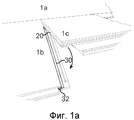
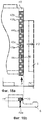
Панель пола данного типа представлена в WO 2008/004960 (заявитель Valinge Innovation AB) и WO 2008/017301 (Schulte). Основные принципы показаны на фиг.1а-1d.A floor panel of this type is presented in WO 2008/004960 (Applicant Valinge Innovation AB) and WO 2008/017301 (Schulte). The basic principles are shown in figa-1d.
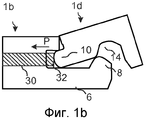
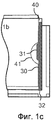
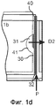
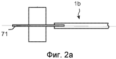
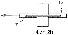
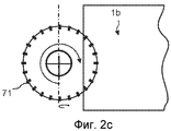
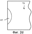
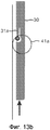
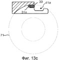
На фиг.1а показано, что два смежных коротких ребра в первом ряду могут быть заблокированы смещаемым шпунтом (30), который смещают, как показано на фиг.1b, посредством бокового проталкивания в одном участке (32) ребра, когда смежные короткие ребра 1b, 1с отогнуты вниз и расположены в одной плоскости. Данная вертикальная укладка посредством «бокового проталкивания», которое обычно обеспечивается давлением Р от длинной стороны третьей панели 1d во втором ряду, смещает отдельный и смещаемый шпунт 30 вдоль стыкового соединения 1b коротких ребер, а также перпендикулярно направлению D2 стыкового соединения так, что часть шпунта смещается в шпунтовой паз 20 смежного короткого ребра 1с. На фиг.1с показано, что смещаемый шпунт 30 расположен в пазу 40 смещения, который содержит полость 41. Данная полость взаимодействует с выступом 31 на смещаемом шпунте так, что смещаемый шпунт 30, когда его проталкивают вдоль ребра и паза смещения, также смещается перпендикулярно ребру в направлении D2 и в шпунтовой паз 20 смежной панели. На фиг.2а-2d показан известный способ образования полости 41. Вращающийся инструмент 71, такой как тонкая дисковая пила, вращается в горизонтальной плоскости НР, параллельной поверхности панели и образует полость 41. Основной недостаток заключается в том, что инструмент образует полость 41 со значительной глубиной, как показано на фиг.2d.On figa shows that two adjacent short ribs in the first row can be blocked by a movable tongue (30), which is displaced, as shown in fig.1b, by lateral pushing in one section (32) of the ribs, when adjacent
Блокировочная система с боковым проталкиванием в соответствии с известной технологией, которая требует образования паза смещения, который не является параллельным ребру, является очень сложной для осуществления, а глубокие пазы будут оказывать негативное влияние на стойкость и прочность ребра панели. Как вариант, могут быть использованы клиновые шпунты, состоящие обычно из двух деталей, которые не являются параллельными ребру. Такие шпунты являются дорогими и сложными для изготовления и вставки в ребро.A side push locking system in accordance with known technology that requires an offset groove that is not parallel to the rib is very difficult to implement and deep grooves will adversely affect the durability and strength of the panel rib. Alternatively, wedge tongues can be used, usually consisting of two parts that are not parallel to the rib. Such dowels are expensive and difficult to manufacture and insert into the rib.
Основной недостаток таких систем с боковым проталкиванием по сравнению с другими механическими блокировочными системами заключается в том, что сложно образовать полости, которые взаимодействуют с выступом на смещаемом шпунте, точным и экономически эффективным способом и устранить негативные влияния на стойкость и прочность ребра панели.The main disadvantage of such systems with lateral pushing in comparison with other mechanical interlocking systems is that it is difficult to form cavities that interact with the protrusion on the movable tongue in an accurate and cost-effective way and eliminate the negative effects on the durability and strength of the panel edges.
ОПРЕДЕЛЕНИЕ НЕКОТОРЫХ ТЕРМИНОВDEFINITION OF SOME TERMS
В приведенном ниже описании, видимая поверхность установленной панели пола называется «лицевой поверхностью», а противоположная сторона панели пола, обращенная к бетонному основанию пола, называется «задней поверхностью». Ребро между передней и задней поверхностью называется «соединительным ребром». Если это не определено как-то иначе, то «верхний» и «нижний» означает около передней поверхности и около задней поверхности. «Внутренний» и «внешний» означает к или от центра панели. «Горизонтальная плоскость» означает плоскость, которая проходит параллельно внешней части поверхностного слоя. Непосредственно расположенные рядом верхние части двух смежных соединительных ребер двух соединенных панелей пола совместно образуют «вертикальную плоскость», перпендикулярную горизонтальной плоскости. «Горизонтально» означает параллельно горизонтальной плоскости, а «вертикально» - параллельно вертикальной плоскости.In the description below, the visible surface of the installed floor panel is called the “front surface”, and the opposite side of the floor panel facing the concrete base of the floor is called the “back surface”. The rib between the front and rear surfaces is called the “connecting rib." Unless otherwise defined, then “upper” and “lower” means near the front surface and near the rear surface. “Internal” and “external” means to or from the center of the panel. "Horizontal plane" means a plane that runs parallel to the outer part of the surface layer. The immediately adjacent upper parts of two adjacent connecting ribs of two connected floor panels together form a “vertical plane” perpendicular to the horizontal plane. “Horizontally” means parallel to the horizontal plane, and “vertically” means parallel to the vertical plane.
«Стыковое соединение» или «блокировочная система» означают взаимодействующие соединительные средства, которые соединяют панели пола вертикально и/или горизонтально. «Панель с рейкой» означает ребро панели, которое содержит рейку и блокировочный элемент, а «панель с пазом» означает ребро панели, которое содержит блокировочный паз, который взаимодействует с блокировочным элементом во время горизонтальной блокировки.“Butt joint” or “interlock system” means cooperative connecting means that connect floor panels vertically and / or horizontally. A “panel with a rail” means an edge of a panel that contains a rail and a locking element, and a “panel with a slot” means an edge of a panel that contains a locking groove that interacts with the locking element during horizontal locking.
«Укладка с вертикальным проталкиванием» означает способ установки, в котором короткие ребра двух панелей блокируются, когда они расположены плоско на бетонном основании пола после поворачивания. Вертикальная блокировка осуществляется посредством бокового проталкивания, которое смещает отдельный шпунт в направлении длины коротких ребер. Горизонтальная блокировка в обычных системах сгибания вниз осуществляется таким же образом, как и в случае систем поворота с блокировочным элементом в одном ребре панели с рейкой, который взаимодействует с блокировочным пазом на другом ребре панели с пазом. «Блокировочная система с боковым проталкиванием» означает блокировочную систему, которая может быть заблокирована методом укладки с вертикальным проталкиванием."Vertical pushing laying" means an installation method in which the short ribs of two panels are locked when they are flat on the concrete base of the floor after turning. Vertical locking is achieved by lateral pushing, which biases a single sheet pile in the length direction of the short ribs. Horizontal locking in conventional downward folding systems is carried out in the same way as in the case of rotation systems with a locking element in one edge of the panel with a rail that interacts with the locking groove on the other edge of the panel with the groove. “Lateral pushing locking system” means a locking system that can be locked by the vertical pushing method.
«Ширина шпунта» означает максимальное расстояние между двумя параллельными линиями вдоль длины шпунта, которые находятся в контакте с самой внешней и внутренней частью шпунта.“Groove width” means the maximum distance between two parallel lines along the length of the tongue that are in contact with the outer and inner part of the tongue.
Основной задачей настоящего изобретения является улучшение функции и прочности блокировочной системы с боковым проталкиванием и в частности тех деталей, которые вызывают перемещение смещаемого шпунта перпендикулярно ребру из одного паза и в смежный паз, когда смещаемый шпунт перемещается вдоль ребра.The main objective of the present invention is to improve the function and strength of the blocking system with lateral pushing, and in particular of those parts that cause the displaced tongue to move perpendicular to the rib from one groove and into the adjacent groove when the displaced tongue is moved along the rib.
В соответствии с первым аспектом изобретения панель пола содержит блокировочную систему, содержащую смещаемый шпунт в пазу смещения в первом ребре и шпунтовой паз в смежных вторых ребрах для вертикальной блокировки. Блокировочная рейка с блокировочным элементом в первом ребре взаимодействует с блокировочным пазом во втором ребре для горизонтальной блокировки. Смещаемый шпунт содержит выступ, а паз смещения содержит полость, так что выступ скользит относительно стенки полости и в первом направлении, перпендикулярном ребру, когда смещаемый шпунт перемещают во втором направлении вдоль ребра. Перемещение в первом направлении вызывает вхождение смещаемого шпунта в шпунтовой паз, в результате чего ребра блокируются вертикально. Полость продолжается вертикально вниз к задней стороне панели.According to a first aspect of the invention, the floor panel comprises a locking system comprising a sliding tongue in an offset groove in the first rib and a tongue groove in adjacent second ribs for vertical locking. The locking rail with the locking element in the first rib interacts with the locking groove in the second rib for horizontal locking. The displaced tongue contains a protrusion, and the offset groove contains a cavity, so that the protrusion slides relative to the wall of the cavity and in the first direction perpendicular to the rib, when the displaced tongue is moved in the second direction along the rib. Moving in the first direction causes the sliding tongue to enter the tongue groove, as a result of which the ribs are locked vertically. The cavity extends vertically down to the rear of the panel.
Преимущество состоит в том, что для образования полостей может быть использована простая обработка резанием, причем такое образование не будет оказывать негативного влияния на прочность и стойкость ребра.The advantage is that a simple cutting treatment can be used to form the cavities, and this formation will not adversely affect the strength and durability of the rib.
В соответствии с предпочтительным вариантом осуществления полость представляет собой глухое отверстие, окруженное по существу вертикальной стенкой.According to a preferred embodiment, the cavity is a blind hole surrounded by a substantially vertical wall.
Такая полость обеспечивает очень стойкое ребро, при этом должно быть удалено минимальное количество материала.Such a cavity provides a very stable rib, while a minimal amount of material must be removed.
В соответствии с вторым аспектом изобретения панель пола содержит блокировочную систему, содержащую смещаемый шпунт в пазу смещения в первом ребре и шпунтовой паз в смежных вторых ребрах для вертикальной блокировки. Блокировочная рейка с блокировочным элементом в первом ребре взаимодействует с блокировочным пазом во втором ребре для горизонтальной блокировки. Смещаемый шпунт содержит выступ, а паз смещения содержит полость, так что выступ скользит относительно стенки полости и в первом направлении, перпендикулярном ребру, когда смещаемый шпунт перемещают во втором направлении вдоль ребра. Перемещение в первом направлении вызывает вхождение смещаемого шпунта в шпунтовой паз, в результате чего ребра блокируются вертикально. Выступ является гибким и выполнен с возможностью вызывания горизонтального предварительного натяга относительно шпунтового паза.According to a second aspect of the invention, the floor panel comprises a locking system comprising a sliding tongue in an offset groove in the first rib and a tongue groove in adjacent second edges for vertical locking. The locking rail with the locking element in the first rib interacts with the locking groove in the second rib for horizontal locking. The displaced tongue contains a protrusion, and the offset groove contains a cavity, so that the protrusion slides relative to the wall of the cavity and in the first direction perpendicular to the rib, when the displaced tongue is moved in the second direction along the rib. Moving in the first direction causes the sliding tongue to enter the tongue groove, as a result of which the ribs are locked vertically. The protrusion is flexible and configured to cause a horizontal preload relative to the tongue groove.
Данный второй аспект обеспечивает преимущества в том, что могут быть уменьшены негативные влияния технологических допусков и может быть обеспечено повышенное качество блокировки.This second aspect provides advantages in that the negative effects of technological tolerances can be reduced and improved blocking quality can be ensured.
В соответствии с третьим аспектом изобретения панель пола содержит блокировочную систему, содержащую смещаемый шпунт в пазу смещения в первом ребре и шпунтовой паз в смежных вторых ребрах для вертикальной блокировки. Блокировочная рейка с блокировочным элементом в первом ребре взаимодействует с блокировочным пазом во втором ребре для горизонтальной блокировки. Смещаемый шпунт содержит выступ, а паз смещения содержит полость, так что выступ скользит относительно стенки полости и в первом направлении, перпендикулярном ребру, когда смещаемый шпунт перемещают во втором направлении вдоль ребра. Перемещение в первом направлении вызывает вхождение смещаемого шпунта в шпунтовой паз, в результате чего ребра блокируются вертикально. Выступ расположен на нижней и/или верхней части смещаемого шпунта.According to a third aspect of the invention, the floor panel comprises an interlocking system comprising a sliding tongue in an offset groove in the first rib and a tongue groove in adjacent second ribs for vertical locking. The locking rail with the locking element in the first rib interacts with the locking groove in the second rib for horizontal locking. The displaced tongue contains a protrusion, and the offset groove contains a cavity, so that the protrusion slides relative to the wall of the cavity and in the first direction perpendicular to the rib, when the displaced tongue is moved in the second direction along the rib. Moving in the first direction causes the sliding tongue to enter the tongue groove, as a result of which the ribs are locked vertically. The protrusion is located on the lower and / or upper part of the movable tongue.
Третий аспект обеспечивает преимущество в том, что можно образовать паз смещения с малой глубиной и может быть обеспечена повышенная стойкость и прочность.The third aspect provides an advantage in that a displacement groove with a shallow depth can be formed, and increased durability and strength can be provided.
В соответствии с четвертым аспектом изобретения ряд панелей пола содержит блокировочную систему, содержащую смещаемый шпунт, содержащий основной корпус шпунта и, по меньшей мере, две клиновые детали, расположенные в пазу смещения в первом ребре первой панели пола, взаимодействующих для вертикальной блокировки ребер со шпунтовым пазом в смежном втором ребре второй панели пола. Блокировочная система дополнительно содержит блокировочную рейку с блокировочным элементом в одном ребре, который взаимодействует, для горизонтальной блокировки ребер, с блокировочным пазом в смежном ребре. Основной корпус шпунта содержит, по меньшей мере, два гибких выступа и две выемки. Клиновые детали расположены, по меньшей мере, частично в выемках. Гибкие выступы выполнены с возможностью скольжения относительно клиновых деталей для обеспечения перемещения основного корпуса шпунта перпендикулярно ребрам, и тем самым вызывая вертикальную блокировку ребер. Гибкие выступы находятся в разблокированном положении, по существу смещенном вдоль смещаемого шпунта относительно клиньев, и выполнены с возможностью вызывания предварительного натяга относительно клиновых деталей и шпунтового паза. Основной корпус шпунта содержит фрикционное соединение, которое обеспечивает перемещение вдоль паза смещения и предотвращает выпадение основного корпуса шпунта из паза смещения. Клиновые детали содержат фрикционное соединение, которое предотвращает перемещение клиновых деталей в пазу смещения, когда основной корпус шпунта перемещают вдоль ребра. Клиновые детали и основной корпус шпунта содержат разъемные соединения клиновых деталей, выполненные с возможностью разъединения во время вставки смещаемого шпунта в паз смещения.According to a fourth aspect of the invention, a series of floor panels comprises an interlocking system comprising a movable tongue, comprising a main tongue body and at least two wedge details located in an offset groove in a first rib of the first floor panel cooperating to vertically lock the ribs with a tongue groove in an adjacent second rib of the second floor panel. The locking system further comprises a locking rail with a locking element in one rib that interacts to horizontally lock the ribs with a locking groove in an adjacent rib. The main tongue housing comprises at least two flexible protrusions and two recesses. Wedge parts are located at least partially in the recesses. Flexible protrusions are slidable relative to the wedge parts to allow movement of the tongue main body perpendicular to the ribs, and thereby causing the ribs to be vertically blocked. Flexible protrusions are in an unlocked position, essentially offset along the movable tongue relative to the wedges, and are configured to cause a preload relative to the wedge parts and tongue groove. The main sheet pile body contains a friction joint that provides movement along the bias groove and prevents the tongue main body from falling out of the bias groove. The wedge parts include a friction joint that prevents the wedge parts from moving into the offset groove when the main sheet pile body is moved along the rib. The wedge parts and the main tongue body comprise detachable joints of the wedge parts, which are capable of being disconnected during insertion of the displaced tongue into the offset groove.
Четвертый аспект обеспечивает преимущества в том, что ребро может быть выполнено с использованием только простой обработки резанием, параллельной ребрам, так же как в обычных механических блокировочных системах. Смещаемый шпунт может быть выполнен экономически эффективно в виде цельного элемента и преобразован в элемент, состоящий из двух частей, во время контролируемой вставки шпунта в паз.A fourth aspect provides advantages in that the rib can be made using only simple cutting processing parallel to the ribs, as in conventional mechanical interlock systems. The movable tongue can be made cost-effective as an integral element and converted into a two-piece element during the controlled insertion of the tongue into the groove.
В соответствии с пятым аспектом изобретения создана заготовка шпунтов, содержащая, по меньшей мере, два шпунта, имеющих длину шпунта и соединенных друг с другом. Шпунты выполнены с возможностью отделения друг от друга и вставки в шпунтовой паз панели пола. Каждый шпунт содержит основной корпус шпунта, содержащий, по меньшей мере, два выступа, продолжающихся по существу в направлении длины шпунта, и две выемки. Шпунт содержит две клиновые детали, расположенные, по меньшей мере, частично в или рядом с выемками. Основной корпус шпунта и клиновые детали содержат разъемные соединения клиновых деталей, выполненные с возможностью отсоединения от основного корпуса шпунта во время вставки шпунта в паз.According to a fifth aspect of the invention, a tongue and groove blank is provided comprising at least two tongues having a tongue length and connected to each other. The tongues are configured to separate from each other and insert into the tongue groove of the floor panel. Each sheet pile comprises a sheet pile main body comprising at least two protrusions extending substantially in the direction of the sheet pile length and two recesses. The tongue contains two wedge details located at least partially in or near the recesses. The main sheet pile body and the wedge parts comprise detachable connections of the wedge parts made to detach from the main sheet pile body when the sheet pile is inserted into the groove.
Пятый аспект обеспечивает преимущества в том, что шпунты могут быть изготовлены, обработаны и вставлены в паз простым и экономически эффективным способом.A fifth aspect provides advantages in that the tongues can be manufactured, machined and inserted into the groove in a simple and cost-effective manner.
Все варианты осуществления первого, второго, третьего, четвертого и пятого аспектов могут быть объединены, и гибкий выступ, например, может быть использован вместе с полостью, продолжающейся к задней стороне и расположенной на верхней и/или нижней стороне смещающегося шпунта.All embodiments of the first, second, third, fourth and fifth aspects can be combined, and a flexible protrusion, for example, can be used with a cavity extending to the rear side and located on the upper and / or lower side of the displacement sheet pile.
Изобретение обеспечивает новые варианты осуществления блокировочных систем, предпочтительно, в коротких ребрах, а также в длинных ребрах или в квадратных панелях. Полезными областями для изобретения являются стеновые панели, потолки, наружные применения и панели пола любой формы и из любого материала, например ламината; в частности панели с материалами поверхности, которые содержат термоотверждающиеся смолы, древесину, древесно-волокнистую плиту высокой плотности (high density fiberboard - HDF), фанеру или камень.The invention provides new embodiments of interlock systems, preferably in short ribs, as well as in long ribs or in square panels. Useful areas for the invention are wall panels, ceilings, outdoor applications and floor panels of any shape and of any material, such as a laminate; in particular, panels with surface materials that contain thermosetting resins, wood, high density fiberboard (HDF), plywood or stone.
Почти все варианты осуществления блокировочной системы описаны с пазом смещения и смещаемым шпунтом на панели с рейкой, в основном для упрощения описания. Очевидно, что основной принцип изобретения может быть также использован на стороне блокировочного паза. Шпунт вставляют в паз смещения в одном ребре, которое расположено рядом, и, предпочтительно, над блокировочным пазом, а шпунтовой паз образован в другом ребре, примыкающем к блокировочной рейке и, предпочтительно, по существу над рейкой.Almost all embodiments of the interlock system are described with an offset groove and a movable tongue on a panel with a rail, mainly to simplify the description. Obviously, the basic principle of the invention can also be used on the side of the locking groove. The tongue is inserted into the displacement groove in one rib which is adjacent and preferably above the locking groove, and the tongue groove is formed in the other rib adjacent to the locking rail and preferably substantially above the rail.
Сущность изобретения поясняется на чертежах, где:The invention is illustrated in the drawings, where:
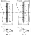
Фиг.1a-d изображают блокировочную систему известного уровня техники.Figa-d depict a locking system of the prior art.
Фиг.2a-c показывают технологию образования полости в ребре панели в соответствии с известным уровнем техники.Figures 2a-c show a cavity formation technology in a panel edge in accordance with the prior art.
Фиг.3a-f показывают технологию образования полости в ребре панели.Figa-f show the technology of the formation of the cavity in the edge of the panel.
Фиг.4a-d показывают альтернативную технологию образования полостей в ребре панели.Figa-d show an alternative technology for the formation of cavities in the edge of the panel.
Фиг.5a-d показывают технологию образования полостей в ребре панели с использованием винтового режущего инструмента.Figures 5a-d illustrate cavity formation technology in a panel edge using a helical cutting tool.
Фиг.6a-b показывают, каким образом могут быть образованы полости во внутреннем слое панели перед наложением поверхностного слоя на внутренний слой.Figures 6a-b show how cavities can be formed in the inner layer of the panel before applying the surface layer to the inner layer.
Фиг.7a-d изображают блокировочную систему с полостями, образованными при помощи дисковых пил.Figa-d depict a locking system with cavities formed using circular saws.
Фиг.8a-е изображают блокировочную систему с полостью, образованной при помощи резцов в виде высверленного глухого отверстия.Figa-e depict a locking system with a cavity formed by cutters in the form of a drilled blind hole.
Фиг.9a-с изображают блокировочную систему с горизонтально открытыми полостями, образованными при помощи резцов.Figures 9a-c show a locking system with horizontally open cavities formed by incisors.
Фиг.10a-е изображают блокировочную систему со смещаемым шпунтом, содержащим гибкие выступы.Figa-e depict a locking system with a movable tongue containing flexible protrusions.
Фиг.11a-d изображают блокировочную систему со смещаемым шпунтом, содержащим выступы в нижней части шпунта.11a-d depict a locking system with a movable tongue containing tabs at the bottom of the tongue.
Фиг.12а-f изображают блокировочную систему со смещаемым шпунтом, содержащим выступы на верхней и/или нижней частях шпунта.Figa-f depict a locking system with a movable tongue containing protrusions on the upper and / or lower parts of the tongue.
Фиг.13a-d изображают гибкие выступы в нижней части смещаемого шпунта и технологии образования стойкого и прочного ребра.Figa-d depict flexible protrusions in the lower part of the movable tongue and the technology of formation of a stable and durable ribs.
Фиг.14a-d изображают блокировочную систему с полостями, образованными при помощи вертикально вращающейся дисковой пилы.Figa-d depict a locking system with cavities formed using a vertically rotating circular saw.
Фиг.15a-b изображают блокировочную систему с полостями, образованными при помощи горизонтально вращающейся дисковой пилы.Figa-b depict a locking system with cavities formed using a horizontally rotating circular saw.
Фиг.16a-b изображают блокировочную систему, использующую полости, которые образованы одновременно с образованием блокировочной системы длинного ребра.Figa-b depict a blocking system using cavities that are formed simultaneously with the formation of a blocking system of a long rib.
Фиг.17a-b изображают блокировочную систему с шипами, которые взаимодействуют с выступами.Figa-b depict a locking system with spikes that interact with the protrusions.
Фиг.18a-e изображают блокировочную систему с шипами, взаимодействующими с выемкой, и вариант осуществления, содержащий смещаемый шпунт на панели с пазом.Figa-e depict a locking system with spikes interacting with a recess, and an embodiment comprising a movable tongue on a panel with a groove.
Фиг.19a-e изображают блокировочную систему с цельным смещаемым шпунтом, который после вставки разделяется на несколько несоединенных частей.Figa-e depict a locking system with a solid movable tongue, which after insertion is divided into several unconnected parts.
Фиг.20a-d изображают вставку шпунта в паз и блокировку блокировочной системы в соответствии с изобретением.Figa-d depict the insertion of the tongue into the groove and the locking of the locking system in accordance with the invention.
Фиг.21a-c изображают способ размещения шпунта в пазу.Figa-c depict a method of placing the tongue in the groove.
Фиг.22a-d изображают заготовку шпунтов и ребро панели пола во время блокировки.Figa-d depict the workpiece tongues and the edge of the floor panel during blocking.
Фиг.23a-f изображают заготовки шпунтов и блокировочную систему на ребре панели пола во время блокировки.Figa-f depict the workpiece sheet pile and the locking system on the edge of the floor panel during blocking.
Фиг.24a-f изображают варианты осуществления в соответствии с основными принципами изобретения.Figa-f depict embodiments in accordance with the basic principles of the invention.
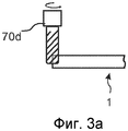
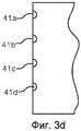
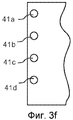
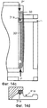
На фиг.3а-3е показана технология образования полостей 41а-d в соответствии с принципом резца. Можно использовать несколько резцов 70а-d, по одному на каждую полость. Образование может осуществляться до или после формирования профиля. На фиг.3а показано, что принцип резца может обеспечить образование полости, размер которой меньше диаметра резца. На фиг.3е показана полость, размер которой больше диаметра резца, если панель и инструмент смещают друг относительно друга. На фиг.3f показана полость, которая выполнена в виде глухого отверстия, содержащего сплошную верхнюю часть и отверстие.On figa-3e shows the technology of the formation of
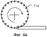
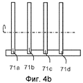
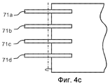
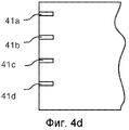
На фиг.4а-d показано, что вышеупомянутое образование может быть также осуществлено с использованием принципа дисковой пилы, когда, предпочтительно, несколько дисковых пил 71а-d, расположенных, предпочтительно, на данных осях, образуют полости 41а-d. В данном варианте осуществления полости меньше диаметра дисковых пил. Конечно, они могут быть равными или большими.Figs 4a-d show that the aforementioned formation can also be carried out using the principle of a circular saw, when, preferably, several
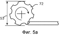
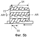
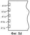
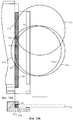
На фиг.5а-d показан способ образования вышеупомянутых полостей 41а-f с использованием принципа винтового режущего инструмента. Такое образование может быть осуществлено с очень высокой экономической эффективностью в непрерывной производственной линии и с высокой точностью, в особенности, если положение и скорость панели точно синхронизированы с положением и скоростью вращения инструмента. Винтовой режущий инструмент 72 может быть использован как отдельное оборудование или, более предпочтительно, как интегрированный участок инструмента в двухстороннем шипорезном станке. Ребро панели перемещают по существу параллельно оси AR вращения винтового режущего инструмента 72. Можно получить любую форму, с круглыми или остроконечными полостями. Резание может осуществляться до, после или одновременно с профильной резкой.Figures 5a-d illustrate a method for forming the
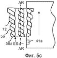
Положение в направлении длины полости, образованной на ребре панели, зависит от положения первого входного зубца 56а инструмента, который входит в контакт с ребром панели, как показано на фиг.5с. Это означает, что вращение инструмента должно быть отрегулировано по отношению к ребру панели, которое перемещают по направлению к инструменту. Положение между полостями может быть очень точным, если вращение инструмента отрегулировано и синхронизировано со скоростью, с которой перемещается панель относительно винтового режущего инструмента. Такая регулировка положения первого входящего зуба и вращения инструмента может быть осуществлена посредством измерения положения ребра панели и скорости перемещающей цепи или ремня или приводного устройства, которое смещает цепь или ремень. Можно обеспечить очень точную обработку резанием полостей и размещать первую полость в заданном положении от ребра с допуском примерно ±0,2 мм или даже меньше. Диаметр 53 показанного винтового режущего инструмента 72 на стороне ES входа, предпочтительно, меньше, чем на противоположной стороне выхода. Однако винтовой режущий инструмент может иметь одинаковый диаметр 53 по всей длине 54. В такой конфигурации инструмента увеличенная глубина резания может быть достигнута при оси вращения, которая расположена под небольшим углом относительно направления подачи ребра панели.The position in the length direction of the cavity formed on the edge of the panel depends on the position of the
Шаг 55 конфигурации инструмента определяет промежуточное расстояние между полостями. Таким образом, очень удобно образовать множество полостей и выступов с очень точными промежуточными расстояниями на значительной длине стыкового соединения. Зубья 56 винтового режущего инструмента, предпочтительно, выполнены из технического алмаза.
Полости могут быть также образованы при помощи большого вращающегося инструмента, такого как дисковая пила, который содержит режущие зубья только на части корпуса инструмента. Это простой вариант принципа винтового режущего инструмента, при этом каждое вращение образует одну полость. Преимущество этого состоит в том, что промежуточное расстояние между полостями может быть изменено посредством регулирования скорости вращения инструмента или скорости подачи панели.Cavities can also be formed using a large rotary tool, such as a circular saw, which contains cutting teeth only on part of the tool body. This is a simple version of the principle of a helical cutting tool, with each rotation forming one cavity. The advantage of this is that the intermediate distance between the cavities can be changed by adjusting the rotation speed of the tool or the feed rate of the panel.
Плановое или неплановое производство останавливается, когда прекращается перемещение панели, что является проблемой, если винтовой режущий инструмент объединен с профилирующим оборудованием, поскольку винтовой режущий инструмент будет разрушать все полости панели, которые находятся в контакте с зубьями инструмента. Данная проблема может быть решена при использовании технологий, включающих перечисленные ниже этапы, причем некоторые или все этапы могут быть использованы независимо или в сочетаниях.Scheduled or unplanned production stops when the panel stops moving, which is a problem if the screw cutting tool is combined with profiling equipment, since the screw cutting tool will destroy all the cavities of the panel that are in contact with the teeth of the tool. This problem can be solved by using technologies that include the steps listed below, with some or all of the steps can be used independently or in combination.
а) Панель всегда останавливают, когда она прошла винтовой режущий инструмент и после полного изготовления всех полостей, расположенных на ребре панели. Данный способ используется для всех плановых остановок. Винтовой режущий инструмент удаляют от ребра панели, когда панель остановлена в положении, которое не обеспечивает полного изготовления всех полостей на ребре. Такие панели с частично образованными полостями обнаруживают и выбраковывают из нормального производства.a) The panel is always stopped when it has passed a screw cutting tool and after the complete manufacture of all cavities located on the edge of the panel. This method is used for all scheduled stops. A helical cutting tool is removed from the edge of the panel when the panel is stopped in a position that does not fully fabricate all cavities on the edge. Such partially formed cavity panels are detected and rejected from normal production.
b) Винтовой режущий инструмент удаляют от ребра панели, когда панель останавливается. Затем устройство перемещения приводят в действие в обратном направлении. Винтовой режущий инструмент возвращают в его первоначальное положение, и панель изготавливают обычным способом.b) The screw cutting tool is removed from the edge of the panel when the panel is stopped. Then, the moving device is driven in the opposite direction. The screw cutting tool is returned to its original position, and the panel is manufactured in the usual way.
с) Винтовой режущий инструмент содержит движущее устройство, которое обеспечивает его перемещение параллельно ребру панели и против направления подачи панелей, когда панель останавливается. Винтовой режущий инструмент перемещают так, что его зубья проходят мимо ребра остановившейся панели. Все полости будут всегда полностью подвергнуты обработке резанием, даже в случае аварийного перебоя. Винтовой режущий инструмент возвращается в его первоначальное положение, когда устройство перемещения приводится в действие, и новую панель изготавливают обычным способом.c) The helical cutting tool comprises a driving device that moves it parallel to the edge of the panel and against the direction of feed of the panels when the panel stops. The screw cutting tool is moved so that its teeth pass past the ribs of the stopped panel. All cavities will always be completely machined, even in the event of an emergency interruption. The screw cutting tool returns to its original position when the moving device is actuated and a new panel is manufactured in the usual manner.
Способ перемещаемого винтового режущего инструмента, который описан в пункте с), обеспечивает преимущества в том, что может быть использовано обычное профилирующее оборудование без какого бы то ни было изменения устройства перемещения или систем управления.The method of a movable helical cutting tool, which is described in paragraph c), provides advantages in that conventional profiling equipment can be used without any modification to the moving device or control systems.
Вышеописанные технологии образования полостей при помощи винтового режущего инструмента могут быть использованы при всех типах обработки резанием панелей и в частности при такой обработке резанием, когда образуются полости, которые содержат детали механической блокировочной системы для панелей пола.The above-described cavity forming techniques using a screw cutting tool can be used for all types of panel cutting and, in particular, with such cutting treatment when cavities are formed that contain parts of a mechanical interlocking system for floor panels.
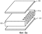
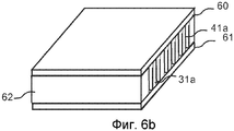
На фиг.6а-b показано, что образование полостей может быть осуществлено до вырезания профиля. Отдельный материал 62 или внутренний слой панели, содержащий полости 41а для выступов, может быть соединен с ребром доски пола и, предпочтительно, приклеен между поверхностным слоем 60 и выравнивающим слоем 61 в деревянном полу или полу из ламината.On figa-b shows that the formation of cavities can be carried out before cutting the profile. A
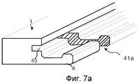
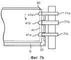
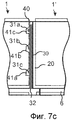
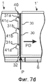
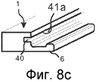
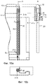
На фиг.7а-d показано, что описанные способы образования полостей в ребре могут быть использованы для перемещения смещаемого шпунта 30 из одного паза 40 смещения в смежный шпунтовой паз 20, как описано со ссылкой на фиг.1а-1d. Одна или несколько полостей 41а-с с горизонтально продолжающимися наклонными или параллельными стенками могут быть образованы посредством прорезания рейки 6, причем такой вариант осуществления и технология являются экономически более эффективными по сравнению с известными способами, в которых для изготовления полостей используются тонкие, горизонтально режущие дисковые пилы. Полости могут быть, предпочтительно, образованы при помощи скачкообразно перемещающихся головок 71а-71с инструмента, установленных на одном валу инструмента, и которые перемещаются по направлению к задней стороне, когда панель перемещается относительно скачкообразно перемещающихся головок инструмента. Панель, конечно, может также перемещаться по отношению к дисковым пилам вертикально или горизонтально. Скачкообразно перемещающиеся головки могут быть установлены в одном станке, который образует длинные ребра, и образование полостей может быть осуществлено экономически эффективно параллельно с образованием блокировочной системы. Скачкообразно перемещающиеся головки могут также перемещаться вдоль направления подачи, причем относительная скорость между перемещением скачкообразно перемещающихся головок и перемещением ребра панели может быть также использована для получения полостей с отверстием, размер которого больше ширины вращающихся инструментов. Для образования полостей или выступов могут быть также использованы скачкообразно перемещающиеся, невращающиеся выскабливающие инструменты. На фиг.7с показан смещаемый шпунт в разблокированном положении с его выступами 31а-с, расположенными в полостях 41а-с. На фиг.7d показано положение блокирования, когда шпунт 30 перемещен вдоль ребра боковым давлением Р, приложенным к участку 32 ребра смещаемого шпунта 30. Во время данного смещения выступ будет скользить вдоль стенок полостей и вызывать смещение шпунта в направлении PD, перпендикулярном ребру, и фиксацию в смежном шпунтовом пазу 20.On figa-d shows that the described methods of forming cavities in the rib can be used to move the
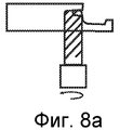
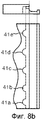
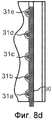
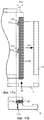
На фиг.8а-8е показан вариант осуществления с полостью 41а, выполненной в виде глухого отверстия. Может быть использован режущий инструмент с диаметром, например, в пределах 5-15 мм, при этом одна или несколько полостей 41а-41с, выполненных в виде глухих отверстий, могут быть образованы с задней стороны, как показано на фиг.8а-8с. Во время обработки резанием панель и/или режущий инструмент перемещают вертикально по направлению друг к другу. Полости могут быть расположены так, что во время блокировки они взаимодействуют с выступами 31а-31d, расположенными на внутренней части шпунта 30, как показано на фиг.8d-8е. Такой вариант осуществления позволяет образовать очень прочное и стойкое ребро, поскольку режущие инструменты будут удалять очень малые количества материала.On figa-8e shows an embodiment with a
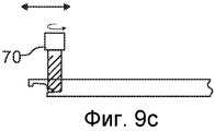
На фиг.9а-9с показан вариант осуществления с полостями 41а-d, образованными при помощи режущего инструмента, причем во время обработки резанием режущий инструмент и/или панель перемещают горизонтально. Использование такой технологии может иметь преимущество в некоторых применениях. Режущие инструменты, например, могут быть неподвижными или прикрепленными к скачкообразно перемещающейся головке инструмента, которая может быть также выполнена с возможностью перемещения вдоль направления подачи панели.9a-9c show an embodiment with
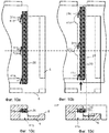
На фиг.10а-10е показано, что выступы 31а-с могут быть выполнены гибкими, и это может быть использовано для компенсации технологических допусков и создания горизонтального предварительного натяга между шпунтом 30 и шпунтовым пазом 20, так что может быть создана вертикальная сила VF давления между верхней частью рейки 6 и смежной панелью, как показано на фиг.10d. Вертикальная сила VF давления, предпочтительно, вызвана поверхностью контакта между шпунтом 30 и шпунтовым пазом 20, которые расположены под небольшим углом относительно горизонтальной плоскости НР.10a-10e show that the
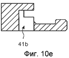
На фиг.11а-d показано, что выступы 31а-с, которые по время блокировки взаимодействуют с полостями 41а-с, могут быть образованы, например, на нижней части смещаемого шпунта 30. Глубина смещаемого шпунта 40 может быть значительно уменьшена, а это увеличит влагостойкость и прочность стыкового соединения.On figa-d shows that the
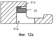
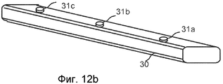
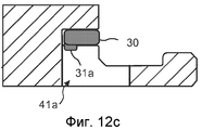
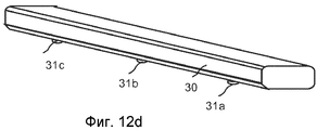
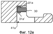
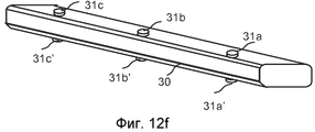
На фиг.12а-12f показано, что выступы 31а-с, 31а'-с' могут быть образованы на верхней и/или нижней части смещаемого шпунта 30. Такие выступы во время блокировки могут взаимодействовать с полостями 41а, расположенными над и/или под основным корпусом смещаемого шпунта 30.12a-12f show that the
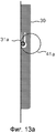
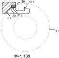
На фиг.13а, 13b показано, что могут быть образованы гибкие выступы 31а, которые выступают вниз и/или вверх из основного корпуса смещаемого шпунта 30. Такой выступ может создавать предварительный натяг подобно тому, как описано выше со ссылкой на фиг.10а-d. На фиг.13с и 13d показано, что выступ 31а на нижней части смещаемого шпунта 30 обеспечивает преимущества в том, что полость 41а может быть выполнена значительно меньшей, как показано на фиг.13d, а это может быть использовано для повышения прочности ребра. Полости, образованные посредством вертикально вращающегося инструмента 71, содержат, предпочтительно, нижнюю часть 81, которая расположена вертикально внутри по отношению к верхней части 82 полости. Это придает ребру достаточную прочность и стойкость и обеспечивает экономически эффективное изготовление.On figa, 13b it is shown that
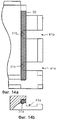
На фиг.14а и 14b показан смещаемый шпунт 30 с выступами 31а,b на нижней части и с полостями 41а,b, образованными при помощи вращающихся дисковых пил. На фиг.14с,d показано, что все варианты осуществления полостей и выступов могут быть использованы для создания противодавления Р' и для сгибания гибкого шпунта 30'. Выступ 31а взаимодействует с полостью 41а и предотвращает перемещение шпунта при приложении бокового давления Р. Шпунт 30 сгибается и фиксируется в шпунтовом пазу. Это может быть использовано для блокировки панелей в первом ряду, где невозможно обеспечить противодавление от длинной стороны в смежном ряду, для того, чтобы согнуть шпунт.On figa and 14b shows a
На фиг.15а,b показано, что горизонтально вращающиеся дисковые пилы 71а-с могут быть использованы для образования полостей 41а-с, которые проходят над и/или под основным корпусом смещаемого шпунта 30 и которые взаимодействуют с выступами 31а,b, расположенными над и/или под основным корпусом шпунта. Одна дисковая пила 71а может быть вертикально смещена относительно другой дисковой пилы 71с. Такие технологии и варианты осуществления могут быть использованы для образования пазов 40 смещения с ограниченной глубиной или для увеличения угла А1 перпендикулярного смещения.On figa, b shows that horizontally rotating
На фиг.16а,b показано, что можно перемещать смещаемый шпунт 30 перпендикулярно стыковому соединению без какой-либо дополнительной механической обработки, помимо той, которая требуется для образования блокировочной системы на длинных и коротких ребрах. Могут быть образованы выступы 31а, 31b в каждом крайнем участке шпунта 30, которые взаимодействуют со шпунтовым пазом 9 длинного ребра и блокировочным пазом 14. В данном варианте осуществления выступ 31b, который взаимодействует с блокировочным пазом 14, является гибким и расположен на нижней стороне основного корпуса шпунта. Этот принцип может быть также использован для сгибания гибкого шпунта, показанного на фиг.14с. Выступ может быть жестким и может быть выполнен, например, в виде простой клиновой детали, выступающей вниз. Вертикальное удлинение выступа 31b должно быть таким, чтобы позволить блокировочному элементу 8 смежного длинного ребра быть расположенным в блокировочном пазу 14 и под выступом 31b, как показано на фиг.16а.On figa, b shows that you can move the
На фиг.17а,b показано, что шипы 42а, 42b могут быть использованы для образования вертикальной стенки в пазу 40 смещения и для перемещения смещаемого шпунта 30 в направлении PD, перпендикулярном стыковому соединению. В показанном варианте осуществления перемещение вызвано одной или несколькими взаимодействующими парами шипов 42а,b и выступов 31а,b. Шипы 42а,b могут быть выполнены из металла, например из мягкой стали или алюминия, или пластмассы или даже твердой древесины. Такие варианты осуществления могут быть также использованы для сгибания гибкого шпунта. Шипы, конечно, могут быть также соединены горизонтально или под углом к пазу 40 смещения.On figa, b shows that the
На фиг.18а,b показано, что перемещение может быть также осуществлено посредством использования одного или нескольких шипов 42а,b, которые взаимодействуют с одной или несколькими выемками 42а,b, образованными, предпочтительно, на внутренней части смещаемого шпунта 30. В данном варианте осуществления смещаемый шпунт содержит одно или несколько фрикционных соединений 44а,b, которые, предпочтительно, выполнены с возможностью сгибания в вертикальном направлении и которые предотвращают выпадение шпунта из паза 40 смещения. Может быть использован другой тип фрикционных соединений.On figa, b shows that the movement can also be carried out by using one or
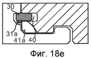
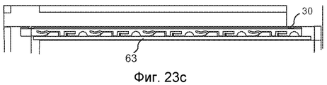
На фиг.18с-е показан вариант осуществления, содержащий смещаемый шпунт 30, расположенный на панели 1с с пазом, который выполнен с возможностью сгибания на панели 1b с рейкой. На фиг.18с и 18d показан смещаемый шпунт 30 в разблокированном положении, а на фиг.18е показано положение блокировки, когда смещаемый шпунт 30 зашел в шпунтовой паз 40. В данном варианте осуществления перпендикулярное перемещение вызвано взаимодействием между одним или несколькими выступами 31а-с, расположенными на нижней стороне смещаемого шпунта, и одной или несколькими полостями 41а-с, которые в данном варианте осуществления расположены под основным корпусом шпунта. Полости 41а-с, предпочтительно, могут быть образованы посредством винтового режущего инструмента. Такой вариант осуществления обеспечивает некоторые преимущества. Для того чтобы образовать полость, из ребра панели должно быть удалено ограниченное количество материала. Кроме того, полости легко образовать, поскольку отсутствует рейка, выступающая из ребра. Смещаемый шпунт 30 также легко вставить в паз смещения, который может быть образован с ограниченной глубиной благодаря тому, что выступ 31а и полость 41а продолжаются вниз из нижней части основного корпуса шпунта.On figs-e shows an embodiment containing a
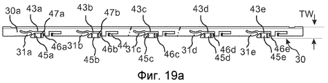
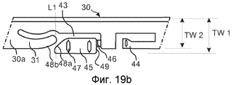
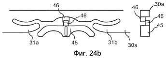
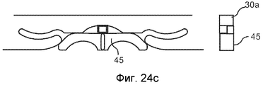
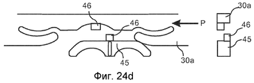
На фиг.19а-е показан смещаемый шпунт 30 в соответствии с одним вариантом осуществления изобретения. Смещаемый шпунт 30 выполнен цельным, предпочтительно, посредством литьевого формования, предпочтительно, термопластичного материала. На фиг.19а показан смещаемый шпунт 30, содержащий основной корпус 30а шпунта и одну или несколько клиновых деталей 45а-е, которые прикреплены к основному корпусу шпунта при помощи соединений 46а-е клиновых деталей, расположенных, предпочтительно, частично в или рядом с шпунтовыми выемками 43а-е, образованными в основном корпусе 30а шпунта. Клиновые детали содержат клиновые фрикционные соединения 47а,b. Основной корпус 30а шпунта содержит, предпочтительно, одно или несколько фрикционных соединений 44 шпунта и, предпочтительно, один или несколько гибких выступов 31а-е, предпочтительно, продолжающихся по существу в направлении длины корпуса 30а смещаемого шпунта.On figa-e shows a
Фиг.19b-19е представляют собой увеличенные сечения шпунта в соответствии с фиг.19а.Figures 19b-19e are enlarged sections of the tongue in accordance with figa.
Шпунтовое фрикционное соединение 44, предпочтительно, выполнено с возможностью сгибания. Такие шпунтовые фрикционные соединения, которые могут быть использованы для создания контролируемого предварительного натяга относительно верхней и/или нижней стенки паза 40 смещения, удерживают шпунт в пазу смещения контролируемым способом и предотвращают выпадение шпунта из паза смещения. Гибкое шпунтовое фрикционное соединение 44 обеспечивает плавное и легкое перемещение вдоль стыкового соединения и устраняет необходимость в жестких технологических допусках при образовании паза смещения. Клиновые детали 45 содержат одно или несколько клиновых фрикционных соединений 47, которые могут быть выполнены в виде вертикально продолжающихся небольших выступов. Такие выступы могут быть также выполнены с возможностью сгибания.The tongue-and-groove friction joint 44 is preferably bendable. Such tongue-and-groove frictional joints that can be used to create a controlled preload relative to the upper and / or lower wall of the
Клиновые фрикционные соединения 47, предпочтительно, выполнены с возможностью создания силы трения, которая больше силы трения, создаваемой шпунтовыми фрикционными соединениями 44. Клиновые фрикционные соединения 47 должны создавать жесткое соединение между клиновыми деталями 45 и пазом 40 смещения и предотвращать перемещение клиновой детали 45, когда во время блокировки основной корпус 30а шпунта перемещают вдоль и перпендикулярно стыковому соединению. Такое жесткое фрикционное соединение может быть выполнено, например, при помощи паза смещения, который выполнен с меньшим, вертикально продолжающимся отверстием во внутренней части, чем в наружной части паза. Внутренняя часть клинового фрикционного соединения может быть прижата к верхней и нижней частям паза смещения во время блокировки, когда основной корпус 30а шпунта создает направленное внутрь давление на клиновую деталь 45.The wedge friction joints 47 are preferably configured to create a friction force that is greater than the friction force created by the tongue and groove friction joints 44. The wedge friction joints 47 should create a rigid connection between the
На фиг.19b показано, что клиновая деталь 45 образует внешнюю часть смещаемого шпунта, когда смещаемый шпунт создан и не соединен с ребром панели. Внешняя часть клиновой детали 45 частично выступает за пределы основного корпуса 30а шпунта. Ширина TW 1 смещаемого шпунта больше ширины TW 2 основного корпуса шпунта. Клиновая деталь содержит расположенную под углом или закругленную клиновую направляющую поверхность 48а и соединительную поверхность 49, которая в данном варианте осуществления, предпочтительно, по существу вертикальная. Гибкий выступ 31 шпунта содержит расположенную под углом или закругленную направляющую поверхность 48b шпунта, которая выполнена с возможностью взаимодействия с клиновой направляющей поверхностью 48а и перемещения смещаемого шпунта перпендикулярно ребру панели, когда боковое давление Р прикладывают к крайнему участку смещаемого шпунта. Предпочтительно, гибкий выступ 31 шпунта и клиновая деталь 45 выполнены с перекрывающимися частями в направлении ширины, которая показана линией L1. В показанном варианте осуществления клиновая направляющая поверхность расположена под углом 45° относительно направления длины смещаемого шпунта 30. Могут быть использованы другие углы. Предпочтительные углы находятся в пределах примерно 25-60 градусов.On fig.19b shows that the
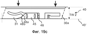
На фиг.19с показано, что клиновая деталь 45, предпочтительно, отделена от основного корпуса 30а шпунта, когда смещаемый шпунт 30 вставлен в паз смещения и прижат к внутренней части 40′ паза 40 смещения. Соединение 46 клиновой детали, предпочтительно, выполнено таким образом, что оно разрывается, когда клиновую деталь 45 вдавливают в выемку 43, образованную в основном корпусе шпунта. В качестве альтернативы, клиновая деталь 45 может быть отделена частично или полностью перед вставкой смещаемого шпунта 31 или когда боковое давление Р прикладывают во время блокировки. Предпочтительно, направляющие поверхности 48а, 48b находятся в контакте или, по меньшей мере, перекрываются в направлении ширины смещаемого шпунта, когда смещаемый шпунт находится в своем внутреннем, разблокированном положении. Такой вариант осуществления будет ограничивать расстояние DD перемещения, которое требуется для осуществления заданного расстояния LD блокировки.FIG. 19c shows that the
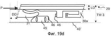
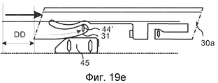
На фиг.19d показано положение основного корпуса 30а шпунта и клиновой детали 45, когда боковое давление Р приложено к краю основного корпуса 30а шпунта и когда основной корпус шпунта смещен вдоль паза 40 смещения и до его конечного расстояния LD блокировки, когда он достигает своей максимальной ширины TW 3 шпунта и когда он заблокирован во внутренней части шпунтового паза 20 ребра смежной панели. Предпочтительно, смещаемый шпунт выполнен таким образом, что основной корпус шпунта может быть дополнительно перемещен для того, чтобы обеспечить конечный поворот и блокировку другой панели 1d в другом ряду, как показано на фиг.1b. На фиг.19е показано, что такое дополнительное перемещение вдоль ребра вызывает сгибание гибкого выступа 31 наружу по направлению к внешним частям основного корпуса шпунта, при этом смещаемый шпунт может быть заблокирован с предварительным натягом. Гибкий выступ является существенной частью данного варианта осуществления и может быть использован для устранения негативных влияний технологических допусков, связанных с образованием пазов и вставкой шпунта в паз. Такой вариант осуществления, который допускает возможность увеличения расстояния DD перемещения, когда расстояние LD блокировки остается по существу неизменным, повышает качество блокировки и уменьшает стоимость изготовления.FIG. 19d shows the position of the tongue
Выступ 31 может быть выполнен таким образом, что предварительный натяг увеличивается, когда основной корпус шпунта перемещают во время окончательной блокировки, как показано на фиг.24а. Предварительный натяг может быть также постоянным, как показано на фиг.24а.The
В соответствии с одним вариантом осуществления, показанным на фиг.19е, выступ 31 может быть выполнен так, что во время блокировки он может сгибаться горизонтально внутрь и наружу, а также вертикально к верхней или нижней части паза смещения. Такая вертикальная гибкость может быть использована для образования фрикционного соединения 44', которое предотвращает выпадение основного корпуса шпунта из паза 40 смещения. Преимущество состоит в том, что более жесткий корпус шпунта может быть образован без каких-либо дополнительных гибких фрикционных соединений на основном корпусе шпунта, кроме выступов 31.In accordance with one embodiment shown in FIG. 19e, the
В данном варианте осуществления смещаемый шпунт имеет три ширины шпунта. Максимальную ширину TW 3, когда он находится в заблокированном положении, минимальную ширину TW 2, когда он находится в разблокированном положении, и промежуточную ширину TW 1 между максимальной и минимальной шириной, когда он изготовлен и не соединен с ребром панели.In this embodiment, the movable tongue has three tongue widths. The maximum width of
Минимальная ширина TW 2 шпунта, предпочтительно, находится в пределах примерно 4-6 мм, максимальная ширина TW 3 шпунта, предпочтительно, находится в пределах 5-8 мм и промежуточная ширина TW 1 шпунта, предпочтительно, находится в пределах 5-7 мм. Расстояние блокировки, предпочтительно, находится в пределах 1-3 мм, и расстояние DD перемещения, предпочтительно, находится в пределах примерно 2-5 мм.The minimum
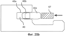
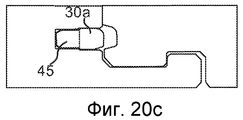
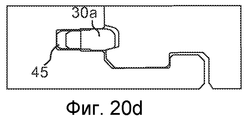
На фиг.20а-b показано, как смещаемый шпунт 30 может быть вставлен в паз 40 смещения при помощи толкателя 67. Паз 40 смещения содержит внутреннюю 40а, 40а' и внешнюю 40b, 40b' пару противоположных и по существу параллельных поверхностей паза. Вертикальное расстояние между внутренними поверхностями 40а, 40а′ паза меньше вертикального расстояния между внешними поверхностями 40b, 40b' паза. Такой паз может быть использован для контролируемого отделения клиновой детали 45 во время вставки, поскольку клиновая деталь будет высвобождена, когда основной корпус 30а шпунта вошел в паз, и он будет предотвращать поворот или скручивание клиновой детали во время вставки. На фиг.20с показано поперечное сечение блокировочной системы в разблокированном положении, а на фиг.20d - в заблокированном положении.Figures 20a-b show how the
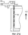
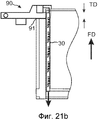
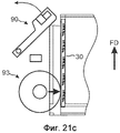
Важно, что шпунт достаточно точно зафиксирован относительно паза смещения. Это может быть осуществлено при помощи установочного оборудования, которое вставляет шпунт в паз, и размещающего устройства 90, которое размещает шпунт на заданном и точном расстоянии от угла панели после вставки, как показано на фиг.21а-21с. Размещающее устройство 90 содержит поверхность 81 контакта с панелью и поверхность 92 контакта с краем шпунта. Эти поверхности могут быть совмещены или смещены в направлении подачи при заданном расстоянии TD шпунта. Смещаемый шпунт, предпочтительно, всегда соединен в положении, которое требует перемещения в одном направлении, предпочтительно, против направления FD подачи, как показано на фиг.21а. Смещаемый шпунт 30 автоматически достигает своего заданного расстояния TD шпунта (которое может быть равным нулю), когда поверхность 91 контакта с панелью находится в контакте с ребром панели, предпочтительно, расположенным перпендикулярно направлению FD подачи, как показано на фиг.21b. На фиг.21с показано, что для окончательной фиксации шпунта в надлежащем положении может быть использовано прижимное колесо 93. По существу вертикальные поверхности 49 клинового соединения, которые показаны на фиг.19с, облегчают контролируемое проталкивание обратно смещаемого шпунта.It is important that the tongue is sufficiently accurately fixed relative to the offset groove. This can be done using installation equipment that inserts the tongue into the groove, and a locating
Перемещение и установка в обоих направлениях могут быть обеспечены посредством, например, цепи или ремня, содержащего несколько толкателей с поверхностями 91 контакта с панелью и поверхностями 92 контакта с краем шпунта. Скорость цепи/ремня может быть увеличена или уменьшена контролируемым способом относительно скорости подачи панели так, что осуществляется контакт между толкателями и двумя противоположными крайними частями, проходящими перпендикулярно направлению подачи, и шпунт проталкивают вдоль по или против направления подачи в его заданное положение.Movement and installation in both directions can be achieved by, for example, a chain or belt containing several pushers with
Вышеописанные технологии могут быть использованы для размещения шпунтов любого типа в любой блокировочной системе.The above technologies can be used to place sheet pile of any type in any blocking system.
Однако описанные выше технологии, включающие вставку и размещение, требуют, чтобы корпус шпунта и клиновые детали были расположены в пазу, а это может создавать проблемы для блокировки, обусловленные, например, неплотно прилегающими клиновыми деталями, которые могут скользить во время блокировки. Поэтому шпунт, наиболее предпочтительно, соединяют и размещают в заданном положении во время соединения, при этом какие-либо дополнительные регулировки не требуются. Такая точная вставка шпунта в паз может быть осуществлена, если скорость толкателя или молотка 67, который вставляет шпунт, синхронизирована со скоростью цепи или ремня, который перемещает ребро панели относительно вставляющего оборудования. Такая точная и контролируемая вставка может быть использована для вставки шпунта любого типа или разделения деталей в пазу.However, the above-described technologies, including insertion and placement, require that the tongue body and the wedge parts are located in the groove, and this can create problems for locking due to, for example, loose wedge parts that may slip during locking. Therefore, the tongue is most preferably connected and placed in a predetermined position during connection, without any additional adjustments being required. Such accurate insertion of the tongue into the groove can be achieved if the speed of the pusher or
Для осуществления блокировки может быть достаточно одной шпунтовой полости и одной клиновой детали, в особенности, если гибкий выступ используется в одном крайнем участке, который взаимодействует с угловым участком панели. Однако предпочтительно использовать, по меньшей мере, две шпунтовые полости и клиновые детали. Такой вариант осуществления обеспечивает более легкое и более контролируемое перемещение и более прочную вертикальную блокировку.One tongue-and-groove cavity and one wedge part may be sufficient for blocking, in particular if the flexible protrusion is used in one extreme portion that interacts with the corner portion of the panel. However, it is preferable to use at least two tongue-and-groove cavities and wedge details. Such an embodiment provides easier and more controlled movement and stronger vertical locking.
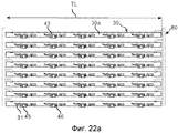
На фиг.22а показана заготовка 80 шпунтов, содержащая несколько смещаемых шпунтов 30 в соответствии с вариантами осуществления изобретения.On figa shows the
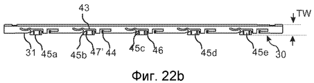
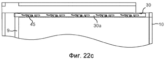
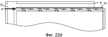
На фиг.22b показан смещаемый шпунт 30, который отделен от заготовки 80 шпунтов. На фиг.22с показан смещаемый шпунт в соединенном положении, когда клиновые детали 45 отделены от основного корпуса 30а шпунта. На фиг.22d показан смещаемый шпунт 30 в наружном и заблокированном положении, когда боковое давление Р приложено к краю шпунта.On fig.22b shows a
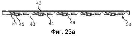
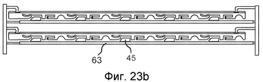
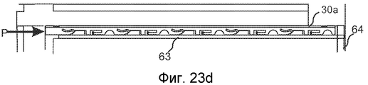
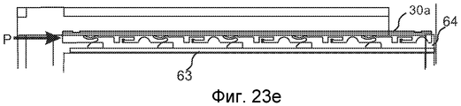
На фиг.23а показано, что для экономии материала в основном корпусе шпунта могут быть образованы выемки 43'. На фиг.23b показано, что клиновые детали 45 могут быть соединены с неподвижным клиновым соединением 63. На фиг.23с-f показано, что клинья могут быть размещены автоматически и что никаких фрикционных соединений не требуется. Неподвижное клиновое соединение 63 перемещается посредством основного корпуса 30а шпунта до тех пор, пока край неподвижного клинового соединения 63 не приходит в контакт с перпендикулярным ребром 64, преимущественно длинным ребром, смежной панели в смежном ряду, как показано на фиг.23d. Клинья предохранены от дополнительного перемещения, а основной корпус 30а шпунта будет перемещаться перпендикулярно ребру, как показано на фиг.23е.On figa shows that to save material in the main body of the tongue can be formed recesses 43 '. On fig.23b shows that the
На фиг.23f показано, что неподвижное клиновое соединение может содержать клиновый крючок 69, который соединен с пазом, образованным на ребре, проходящем перпендикулярно основному корпусу 30а шпунта. В данном варианте паз, который преимущественно используется для приема шпунта длинного ребра, имеет увеличенную глубину 66, которая, предпочтительно, образована при помощи инструмента со скачкообразно перемещающейся головкой. Преимущество состоит в том, что клиновое соединение не нужно приспосабливать к ширине панели.On fig.23f shows that the fixed wedge connection may include a wedge hook 69, which is connected to the groove formed on the rib extending perpendicular to the main body 30A of the tongue. In this embodiment, the groove, which is mainly used to receive the tongue of a long rib, has an increased depth of 66, which is preferably formed using a tool with a stepwise moving head. The advantage is that the wedge connection does not need to be adapted to the width of the panel.
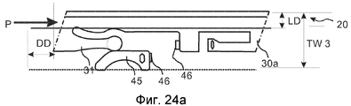
На фиг.24а показано, что выступ 31 и/или клиновая деталь 45 может быть гибкой и создавать предварительный натяг относительно шпунтового паза.On figa shows that the
На фиг.24b-24d показано, что выступы 31а, 31b могут быть выполнены на каждой стороне клина и что перемещение основного корпуса 30а шпунта может быть осуществлено в обоих направлениях вдоль ребра. В данном варианте осуществления соединение 46 клиновой детали выполнено на внешней части клиновой детали 45.On fig.24b-24d it is shown that the
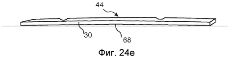
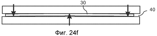
На фиг.24е и 24f показан простой способ получения фрикционного соединения, которое предотвращает выпадение смещаемого шпунта любого типа из паза 40 смещения. Смещаемый шпунт 30 выполнен таким образом, что он немного изогнут вертикально вдоль его длины. Такой изгиб может продолжаться по всему шпунту или по ограниченным участкам и может быть использован для создания предварительного натяга относительно верхней и нижней части паза 40 смещения. Шпунт, предпочтительно, после отделения от заготовки шпунтов, сжимают посредством вставляющего оборудования таким образом, что изгиб устраняется, и вставляют в паз. Изгиб может быть получен множеством способов. Простой изгиб шпунта, выполненного из HDF, например, может быть осуществлен посредством локального сжатия 68 с верхней и/или нижней стороны основного корпуса. Могут быть также использованы разные плотности, и это может быть осуществлено, например, посредством обработки резанием HDF по существу только с одной стороны. Кроме того, HDF может быть упрочнена и изогнута контролируемым способом, если, например, один слой, предпочтительно, бумаги, пропитанной термоотверждающейся смолой, прикладывают только с одной стороны. Такой слой может быть ламинирован и снабжен поверхностной структурой, которая облегчает скольжение и создает заданную силу трения относительно паза. Вышеописанное фрикционное соединение может быть использовано независимо для соединения шпунта любого типа, предпочтительно смещаемого шпунта, с пазом или в сочетаниях с другими фрикционными соединениями или шпунтами в соответствии с описанными вариантами осуществления.24e and 24f show a simple method for producing a friction joint that prevents any type of tongue and groove tongue from falling out of the
Все варианты осуществления шпунтов могут быть выполнены в материале, содержащем древесные волокна. Такие материалы могут представлять собой древесные волокна, смешанные с термопластичным материалом, или древесину, содержащую термоотверждающуюся смолу. Могут быть использованы экструдированные, литьевые или листовые материалы. Предпочтительным материалом является HDF и, предпочтительно, HDF с плотностью выше 700 кг/см2. Сочетания обработки резанием, и/или штамповки, и/или сжатия материала могут быть использованы для образования шпунтов или заготовок шпунтов с довольно сложными трехмерными формами, которые могут быть использованы в любом применении, где отдельный и/или смещаемый шпунт используется для блокировки смежных ребер панелей, предпочтительно, панелей пола. Данная технология является экономически очень эффективной и экологически безопасной.All embodiments of the tongue and groove can be made in a material containing wood fibers. Such materials may be wood fibers mixed with a thermoplastic material, or wood containing a thermosetting resin. Extruded, injection molded, or sheet materials may be used. The preferred material is HDF and preferably HDF with a density higher than 700 kg / cm 2 . Combinations of cutting, and / or stamping, and / or compression of the material can be used to form sheet piles or sheet piles with fairly complex three-dimensional shapes that can be used in any application where a separate and / or offset sheet pile is used to block adjacent panel edges preferably floor panels. This technology is very cost effective and environmentally friendly.
Claims (23)
отличающаяся тем, что полость продолжается вертикально вниз к задней стороне панели пола.1. A group of floor panels (1) with a locking system containing a displaceable tongue (30) in the offset groove (40) in the first edge of the first floor panel, interacting to vertically lock the ribs with the tongue groove (20) in adjacent second edges of the second floor panel, moreover, the locking system further comprises a locking rail (6) with a locking element (8) in one rib that interacts to horizontally lock the ribs with a locking groove (14) in an adjacent rib, the displaced tongue containing a protrusion (31a), and the displacement groove contains cavity (41a), and the protrusion is made with the possibility of sliding relative to the wall of the cavity to ensure the movement of the tongue in the first direction (PD) perpendicular to the ribs, and thereby the vertical locking of the ribs,
characterized in that the cavity extends vertically downward to the rear side of the floor panel.
отличающаяся тем, что выступ является гибким и выполнен с возможностью обеспечения горизонтального предварительного натяга относительно шпунтового паза (20).6. A group of floor panels (1) with a locking system containing a displaceable tongue (30) in the offset groove (40) in the first edge of the first floor panel, interacting to vertically lock the ribs with the tongue groove (20) in adjacent second edges of the second floor panel, moreover, the locking system further comprises a locking rail (6) with a locking element (8) in one rib that interacts to horizontally lock the ribs with a locking groove (14) in an adjacent rib, and the displaced tongue contains a protrusion (31a), and the offset groove contains cavity (41a), and the protrusion is made with the possibility of sliding relative to the wall of the cavity to ensure movement of the movable tongue in the first direction (PD) perpendicular to the ribs, and thereby the vertical locking of the ribs,
characterized in that the protrusion is flexible and is configured to provide horizontal preload relative to the tongue groove (20).
отличающаяся тем, что выступ расположен в нижней и/или верхней части смещаемого шпунта.8. A group of floor panels (1) with an interlocking system containing a movable tongue (30) in the offset groove (40) in the first edge of the first floor panel, interacting to vertically lock the ribs with the tongue groove (20) in adjacent second edges of the second floor panel, moreover, the locking system further comprises a locking rail (6) with a locking element (8) in one rib, which interacts with the locking groove (14) in an adjacent rib, and the displaced tongue contains a protrusion (31A), and the offset groove contains a cavity (41a), moreover, the protrusion is made with the possibility of sliding relative to the wall of the cavity to ensure the movement of the tongue in the first direction (PD) perpendicular to the ribs, and thereby the vertical locking of the ribs,
characterized in that the protrusion is located in the lower and / or upper part of the movable tongue.
отличающаяся тем, что гибкие выступы (31а, b) в разблокированном положении по существу смещены вдоль смещаемого шпунта (30) относительно клиновых деталей (45а, b) и выполнены с возможностью обеспечения предварительного натяга относительно клиновых деталей (45а, b) и шпунтового паза (20), причем основной корпус (30а) шпунта содержит фрикционное соединение (44), обеспечивающее перемещение вдоль паза смещения и предотвращающее выпадение основного корпуса (30а) шпунта из паза (44) смещения, при этом клиновые детали (45а, b) содержат фрикционное соединение (47), которое предотвращает перемещение клиновых деталей в пазу (40) смещения, когда основной корпус шпунта перемещают вдоль ребра, причем клиновые детали (45а, b) и основной корпус (30а) шпунта содержат разъемные соединения (46а, b) клиновых деталей, выполненные с возможностью высвобождения во время вставки смещаемого шпунта (30) в паз (40) смещения.12. A group of floor panels (1) with an interlocking system comprising a movable tongue (30), comprising a main tongue body (30a) and at least two wedge details (45a, b) located in the offset groove (40) in the first a rib of the first floor panel cooperating for vertical locking of the ribs with a tongue groove (20) in an adjacent second rib of the second floor panel, the locking system further comprising a locking rail (6) with a locking element (8) in one rib that interacts for horizontal locking ribs, with locks a groove (14) in an adjacent rib, wherein the tongue main body (30a) comprises at least two flexible protrusions (31a, b) and two recesses (43a, b), and the wedge parts (45a, b) are arranged along at least partially in the recesses (43a, b), the protrusions being slidable relative to the wedge parts to allow the tongue main body (30a) to move in the first direction (PD) perpendicular to the ribs, thereby causing the ribs to be vertically blocked,
characterized in that the flexible protrusions (31a, b) in the unlocked position are essentially offset along the movable tongue (30) relative to the wedge parts (45a, b) and are configured to preload relative to the wedge parts (45a, b) and the tongue groove ( 20), wherein the tongue main body (30a) contains a friction joint (44) that provides movement along the displacement groove and prevents the tongue main body (30a) from falling out of the displacement groove (44), while the wedge parts (45a, b) contain a friction joint (47) to which prevents the wedge parts from moving into the displacement groove (40) when the tongue main body is moved along the rib, the wedge parts (45a, b) and the tongue main body (30a) having detachable joints (46a, b) of the wedge details while inserting the displaced tongue (30) into the offset groove (40).
Applications Claiming Priority (5)
| Application Number | Priority Date | Filing Date | Title |
|---|---|---|---|
| SEPCT/SE2009/050103 | 2009-01-30 | ||
| PCT/SE2009/050103 WO2009116926A1 (en) | 2008-01-31 | 2009-01-30 | Mechanical locking of floor panels, methods to install and uninstall panels, a method and an equipement to produce the locking system, a method to connect a displaceable tongue to a panel and a tongue blank |
| SE0900580-2 | 2009-04-29 | ||
| SE0900580 | 2009-04-29 | ||
| PCT/SE2009/051238 WO2010087752A1 (en) | 2009-01-30 | 2009-11-02 | Mechanical lockings of floor panels and a tongue blank |
Publications (2)
| Publication Number | Publication Date |
|---|---|
| RU2011135990A RU2011135990A (en) | 2013-03-10 |
| RU2524091C2 true RU2524091C2 (en) | 2014-07-27 |
Family
ID=42395825
Family Applications (1)
| Application Number | Title | Priority Date | Filing Date |
|---|---|---|---|
| RU2011135990/03A RU2524091C2 (en) | 2009-01-30 | 2009-11-02 | Mechanical locks of floor panels and blank of tongues |
Country Status (22)
| Country | Link |
|---|---|
| US (5) | US8713886B2 (en) |
| EP (3) | EP3505705B1 (en) |
| JP (1) | JP5623429B2 (en) |
| CN (2) | CN102301079B (en) |
| AU (1) | AU2009338857B2 (en) |
| CA (2) | CA2749464C (en) |
| DK (1) | DK2391783T3 (en) |
| ES (2) | ES2661193T3 (en) |
| HR (2) | HRP20180134T1 (en) |
| HU (1) | HUE036375T2 (en) |
| IL (1) | IL213931A (en) |
| LT (1) | LT2391783T (en) |
| MX (1) | MX2011008076A (en) |
| MY (1) | MY157512A (en) |
| NO (1) | NO2391783T3 (en) |
| NZ (1) | NZ593953A (en) |
| PL (3) | PL2391783T3 (en) |
| PT (2) | PT2391783T (en) |
| RU (1) | RU2524091C2 (en) |
| SG (1) | SG172871A1 (en) |
| UA (1) | UA103515C2 (en) |
| WO (1) | WO2010087752A1 (en) |
Families Citing this family (145)
| Publication number | Priority date | Publication date | Assignee | Title |
|---|---|---|---|---|
| EP2281978B1 (en) | 2002-04-03 | 2016-10-12 | Välinge Innovation AB | Method of attaching a strip to a floorboard |
| US7454875B2 (en) | 2004-10-22 | 2008-11-25 | Valinge Aluminium Ab | Mechanical locking system for floor panels |
| US7841144B2 (en) | 2005-03-30 | 2010-11-30 | Valinge Innovation Ab | Mechanical locking system for panels and method of installing same |
| DK1936068T3 (en) | 2004-10-22 | 2012-03-19 | Vaelinge Innovation Ab | Method of providing floor panels with a mechanical locking system |
| US20130139478A1 (en) | 2005-03-31 | 2013-06-06 | Flooring Industries Limited, Sarl | Methods for packaging floor panels, as well as packed set of floor panels |
| BE1016938A6 (en) | 2005-03-31 | 2007-10-02 | Flooring Ind Ltd | Floor panel manufacturing method, involves providing panels at lower side with guiding groove and providing two opposite sides with profiled edge regions that comprise coupling parts |
| US8061104B2 (en) | 2005-05-20 | 2011-11-22 | Valinge Innovation Ab | Mechanical locking system for floor panels |
| SE530653C2 (en) | 2006-01-12 | 2008-07-29 | Vaelinge Innovation Ab | Moisture-proof floor board and floor with an elastic surface layer including a decorative groove |
| BE1017157A3 (en) | 2006-06-02 | 2008-03-04 | Flooring Ind Ltd | FLOOR COVERING, FLOOR ELEMENT AND METHOD FOR MANUFACTURING FLOOR ELEMENTS. |
| SE533410C2 (en) | 2006-07-11 | 2010-09-14 | Vaelinge Innovation Ab | Floor panels with mechanical locking systems with a flexible and slidable tongue as well as heavy therefore |
| US11725394B2 (en) | 2006-11-15 | 2023-08-15 | Välinge Innovation AB | Mechanical locking of floor panels with vertical folding |
| US8689512B2 (en) | 2006-11-15 | 2014-04-08 | Valinge Innovation Ab | Mechanical locking of floor panels with vertical folding |
| SE531111C2 (en) | 2006-12-08 | 2008-12-23 | Vaelinge Innovation Ab | Mechanical locking of floor panels |
| US8353140B2 (en) | 2007-11-07 | 2013-01-15 | Valinge Innovation Ab | Mechanical locking of floor panels with vertical snap folding |
| RU2485265C2 (en) | 2008-01-31 | 2013-06-20 | Велинге Инновейшн Белджиум Бвба | Mechanical fixator of floor panels, methods for installation and disassembly of panels, method and equipment for creation of locking device, method to connect shifted dowel with panel and dowel blank |
| US8505257B2 (en) | 2008-01-31 | 2013-08-13 | Valinge Innovation Ab | Mechanical locking of floor panels |
| US11235565B2 (en) | 2008-04-07 | 2022-02-01 | Valinge Innovation Ab | Wood fibre based panels with a thin surface layer |
| US8112967B2 (en) | 2008-05-15 | 2012-02-14 | Valinge Innovation Ab | Mechanical locking of floor panels |
| AU2009338857B2 (en) | 2009-01-30 | 2016-03-10 | Valinge Innovation Ab | Mechanical lockings of floor panels and a tongue blank |
| US11725395B2 (en) | 2009-09-04 | 2023-08-15 | Välinge Innovation AB | Resilient floor |
| US8365499B2 (en) | 2009-09-04 | 2013-02-05 | Valinge Innovation Ab | Resilient floor |
| EP2524093B1 (en) | 2010-01-12 | 2020-02-05 | Välinge Innovation AB | Mechanical locking system for floor panels |
| EP3524754B1 (en) | 2010-01-14 | 2020-10-28 | Unilin, BV | Floor panel assembly |
| RU2570035C2 (en) | 2010-01-15 | 2015-12-10 | Велинге Инновейшн Аб, | Structure made at heating and pressure |
| KR101875588B1 (en) | 2010-01-15 | 2018-07-06 | 뵈린게 이노베이션 에이비이 | Bright colored surface layer |
| US8402707B2 (en) * | 2010-01-29 | 2013-03-26 | Royal Group Inc. | Interlocking panel system |
| BR112012018285B1 (en) | 2010-02-04 | 2020-02-18 | Välinge Innovation AB | SET OF FLOOR PANELS |
| US8234830B2 (en) | 2010-02-04 | 2012-08-07 | Välinge Innovations AB | Mechanical locking system for floor panels |
| US8480841B2 (en) | 2010-04-13 | 2013-07-09 | Ceralog Innovation Belgium BVBA | Powder overlay |
| US10899166B2 (en) | 2010-04-13 | 2021-01-26 | Valinge Innovation Ab | Digitally injected designs in powder surfaces |
| RU2525556C2 (en) | 2010-04-15 | 2014-08-20 | Спанолюкс Н.В.-Див. Бальтерио | Block of floor panels |
| BE1019331A5 (en) | 2010-05-10 | 2012-06-05 | Flooring Ind Ltd Sarl | FLOOR PANEL AND METHODS FOR MANUFACTURING FLOOR PANELS. |
| US10315219B2 (en) | 2010-05-31 | 2019-06-11 | Valinge Innovation Ab | Method of manufacturing a panel |
| US8806832B2 (en) | 2011-03-18 | 2014-08-19 | Inotec Global Limited | Vertical joint system and associated surface covering system |
| RU2595661C2 (en) | 2011-04-12 | 2016-08-27 | Велинге Инновейшн Аб | Method for production of layer |
| ES2805332T3 (en) | 2011-04-12 | 2021-02-11 | Vaelinge Innovation Ab | Manufacturing method of a building panel |
| MX342546B (en) | 2011-04-12 | 2016-10-03 | Vaelinge Innovation Ab | Powder based balancing layer. |
| UA109938C2 (en) | 2011-05-06 | 2015-10-26 | MECHANICAL LOCKING SYSTEM FOR CONSTRUCTION PANELS | |
| FR2975717A1 (en) * | 2011-09-22 | 2012-11-30 | Epi Flooring | Dissociable insert for use in blocking system to block junction between successive strips of e.g. mantle, has locking element moved laterally along direction of groove by lateral pushing of extracting element until being engaged in groove |
| FR2975718B1 (en) * | 2011-05-25 | 2015-01-02 | Inovame | BLADE OF STRUCTURE PLANE OF FACING OR PARQUET |
| UA114715C2 (en) | 2011-07-05 | 2017-07-25 | Сералок Інновейшн Аб | Mechanical locking of floor panels with a glued tongue |
| CA2840714C (en) | 2011-07-11 | 2020-07-07 | Valinge Flooring Technology Ab | Mechanical locking system for floor panels |
| US9725912B2 (en) | 2011-07-11 | 2017-08-08 | Ceraloc Innovation Ab | Mechanical locking system for floor panels |
| US8650826B2 (en) | 2011-07-19 | 2014-02-18 | Valinge Flooring Technology Ab | Mechanical locking system for floor panels |
| DE102012102339A1 (en) * | 2011-07-29 | 2013-01-31 | Hamberger Industriewerke Gmbh | Connection for elastic or plate-shaped components, profile slides and floor coverings |
| US8763340B2 (en) | 2011-08-15 | 2014-07-01 | Valinge Flooring Technology Ab | Mechanical locking system for floor panels |
| US8769905B2 (en) | 2011-08-15 | 2014-07-08 | Valinge Flooring Technology Ab | Mechanical locking system for floor panels |
| US8857126B2 (en) | 2011-08-15 | 2014-10-14 | Valinge Flooring Technology Ab | Mechanical locking system for floor panels |
| UA114892C2 (en) | 2011-08-26 | 2017-08-28 | Сералок Інновейшн Аб | METHOD OF MANUFACTURING MULTIPLE PRODUCTS AND FLOOR PANEL |
| US8920876B2 (en) | 2012-03-19 | 2014-12-30 | Valinge Innovation Ab | Method for producing a building panel |
| US8596013B2 (en) | 2012-04-04 | 2013-12-03 | Valinge Innovation Ab | Building panel with a mechanical locking system |
| US9216541B2 (en) | 2012-04-04 | 2015-12-22 | Valinge Innovation Ab | Method for producing a mechanical locking system for building panels |
| EP3613920B1 (en) | 2012-11-22 | 2024-01-31 | Ceraloc Innovation AB | Mechanical locking system for floor panels |
| US9181698B2 (en) | 2013-01-11 | 2015-11-10 | Valinge Innovation Ab | Method of producing a building panel and a building panel |
| US9194134B2 (en) | 2013-03-08 | 2015-11-24 | Valinge Innovation Ab | Building panels provided with a mechanical locking system |
| PL3392428T3 (en) * | 2013-03-08 | 2020-08-10 | Välinge Innovation AB | Building panels provided with a mechanical locking system |
| AU2014281243B2 (en) | 2013-06-17 | 2018-03-01 | Valinge Innovation Ab | A method of manufacturing a wood-based board and such a wood-based board |
| LT3014034T (en) | 2013-06-27 | 2019-11-11 | Vaelinge Innovation Ab | Building panel with a mechanical locking system |
| UA118967C2 (en) | 2013-07-02 | 2019-04-10 | Велінге Інновейшн Аб | A method of manufacturing a building panel and a building panel |
| EA031216B1 (en) | 2013-07-09 | 2018-12-28 | Сералок Инновейшн Аб | Set of ceramic or stone tiles |
| WO2015010207A1 (en) | 2013-07-24 | 2015-01-29 | Pantev Gueorgui | Self-locking mechanism and paneling |
| US9726210B2 (en) | 2013-09-16 | 2017-08-08 | Valinge Innovation Ab | Assembled product and a method of assembling the product |
| SI3470690T1 (en) | 2013-09-16 | 2022-02-28 | Vaelinge Innovation Ab | An assembled product |
| GB201317450D0 (en) * | 2013-10-02 | 2013-11-13 | Indespension Ltd | Plank and interlocking structure |
| CN105612062A (en) | 2013-10-18 | 2016-05-25 | 瓦林格创新股份有限公司 | A method of manufacturing a building panel |
| CN105636787B (en) | 2013-10-23 | 2020-07-10 | 塞拉洛克创新股份有限公司 | Method for forming decorative wear-resistant layer |
| EP3060728B1 (en) | 2013-10-25 | 2019-04-10 | Ceraloc Innovation AB | Mechanical locking system for floor panels |
| DE102013113109A1 (en) | 2013-11-27 | 2015-06-11 | Guido Schulte | floorboard |
| DE102013113125A1 (en) | 2013-11-27 | 2015-05-28 | Guido Schulte | Floor, wall or ceiling panel and method of making the same |
| DE102013113130B4 (en) | 2013-11-27 | 2022-01-27 | Välinge Innovation AB | Method of manufacturing a floorboard |
| UA119454C2 (en) | 2014-01-10 | 2019-06-25 | Велінге Інновейшн Аб | A furniture panel |
| HRP20220122T1 (en) | 2014-01-10 | 2022-04-15 | Välinge Innovation AB | A method of producing a veneered element |
| US9714672B2 (en) | 2014-01-10 | 2017-07-25 | Valinge Innovation Ab | Panels comprising a mechanical locking device and an assembled product comprising the panels |
| EP3096961B1 (en) | 2014-01-24 | 2022-03-02 | Ceraloc Innovation AB | Digital print with water-based ink on panel surfaces |
| EP3099499A4 (en) | 2014-01-31 | 2017-10-11 | Ceraloc Innovation AB | A method of printing a digital image on a substrate attached to a panel and a water-based ink for digital printing on a substrate |
| US9260870B2 (en) | 2014-03-24 | 2016-02-16 | Ivc N.V. | Set of mutually lockable panels |
| KR102398462B1 (en) | 2014-03-24 | 2022-05-13 | 플로어링 인더스트리즈 리미티드 에스에이알엘 | A set of mutually lockable panels |
| US10030394B2 (en) | 2014-04-10 | 2018-07-24 | Berryalloc Nv | Floor board with universal connection system |
| MX2016014501A (en) | 2014-05-09 | 2017-01-23 | Vaelinge Innovation Ab | Mechanical locking system for building panels. |
| RU2687440C2 (en) | 2014-05-12 | 2019-05-13 | Велинге Инновейшн Аб | Method of making element covered with veneer, and such element covered with veneer |
| US10246883B2 (en) | 2014-05-14 | 2019-04-02 | Valinge Innovation Ab | Building panel with a mechanical locking system |
| US9458634B2 (en) | 2014-05-14 | 2016-10-04 | Valinge Innovation Ab | Building panel with a mechanical locking system |
| US9375085B2 (en) | 2014-07-11 | 2016-06-28 | Valinge Innovation Ab | Panel with a slider |
| EP3169533B1 (en) | 2014-07-16 | 2023-04-26 | Välinge Innovation AB | Method to produce a thermoplastic wear resistant foil |
| US10138636B2 (en) * | 2014-11-27 | 2018-11-27 | Valinge Innovation Ab | Mechanical locking system for floor panels |
| PL3594514T3 (en) | 2014-12-19 | 2023-03-20 | Välinge Innovation AB | Panels comprising a mechanical locking device |
| PL3237704T3 (en) | 2014-12-22 | 2020-05-18 | Ceraloc Innovation Ab | Set of identical floor panels provided with a mechanical locking system |
| JP6879917B2 (en) | 2015-01-14 | 2021-06-02 | ベーリンゲ、イノベイション、アクチボラグVaelinge Innovation Ab | How to manufacture abrasion resistant layers with various glosses |
| CN107208426B (en) | 2015-01-16 | 2019-07-26 | 塞拉洛克创新股份有限公司 | Mechanical locking system for floor panel |
| US10670064B2 (en) | 2015-04-21 | 2020-06-02 | Valinge Innovation Ab | Panel with a slider |
| UA123581C2 (en) * | 2015-04-30 | 2021-04-28 | Велінге Інновейшн Аб | Panel with a fastening device |
| DK3473783T3 (en) | 2015-05-12 | 2020-08-17 | Aladdin Mfg Corp | PROCEDURE FOR MAKING FLOOR TILES |
| US11313123B2 (en) | 2015-06-16 | 2022-04-26 | Valinge Innovation Ab | Method of forming a building panel or surface element and such a building panel and surface element |
| CN108026956B (en) | 2015-09-22 | 2020-07-17 | 瓦林格创新股份有限公司 | Panel comprising a mechanical locking device and assembled product comprising said panel |
| WO2017095314A1 (en) | 2015-12-03 | 2017-06-08 | Välinge Innovation AB | Panels comprising a mechanical locking device and an assembled product comprising the panels |
| CN108367564A (en) | 2015-12-21 | 2018-08-03 | 瓦林格创新股份有限公司 | Manufacture the method and semi-finished product of building panelling |
| DK3407765T3 (en) | 2016-01-26 | 2021-04-26 | Vaelinge Innovation Ab | PANELS INCLUDING A MECHANICAL LOCKING DEVICE FOR OBTAINING A FURNITURE PRODUCT |
| EP3411599B1 (en) | 2016-02-04 | 2021-03-31 | Välinge Innovation AB | A set of panels for an assembled product |
| EP3414462B1 (en) | 2016-02-09 | 2020-10-07 | Välinge Innovation AB | Element and method for providing dismantling groove |
| JP6869991B2 (en) | 2016-02-09 | 2021-05-12 | ベーリンゲ、イノベイション、アクチボラグVaelinge Innovation Ab | A set of panel shape elements for composite elements |
| JP6921834B2 (en) * | 2016-02-15 | 2021-08-18 | ベーリンゲ、イノベイション、アクチボラグVaelinge Innovation Ab | How to form panels for furniture products |
| US11186997B2 (en) | 2016-03-24 | 2021-11-30 | Valinge Innovation Ab | Method for forming a décor on a substrate |
| BR112018071242B1 (en) | 2016-04-25 | 2022-12-06 | Vãlinge Innovation Ab | PLATED ELEMENT AND METHOD OF PRODUCTION OF SUCH PLATED ELEMENT |
| US10828798B2 (en) | 2016-06-29 | 2020-11-10 | Valinge Innovation Ab | Method and device for inserting a tongue |
| US11331824B2 (en) | 2016-06-29 | 2022-05-17 | Valinge Innovation Ab | Method and device for inserting a tongue |
| BR112018076069B1 (en) | 2016-06-29 | 2023-01-17 | Vãlinge Innovation Ab | METHOD AND DEVICE FOR INSERTING A TAG |
| US11045933B2 (en) | 2016-06-30 | 2021-06-29 | Valinge Innovation Ab | Device for inserting a tongue |
| CN109863317A (en) | 2016-10-27 | 2019-06-07 | 瓦林格创新股份有限公司 | Panel component with mechanical locking |
| MY195040A (en) * | 2016-12-22 | 2023-01-04 | Valinge Innovation Ab | Device for Inserting a Tongue into an Insertion Groove in a Panel |
| MY196739A (en) | 2017-05-15 | 2023-05-03 | Valinge Innovation Ab | Elements and a locking device for an assembled product |
| US20210277668A1 (en) | 2017-08-15 | 2021-09-09 | National Nail Corp. | Hidden fastener unit and related method of use |
| US11149445B2 (en) | 2017-08-15 | 2021-10-19 | National Nail Corp. | Hidden fastener unit and related method of use |
| US11898357B2 (en) | 2017-08-15 | 2024-02-13 | National Nail Corp. | Hidden fastener unit and related method of use |
| USD924044S1 (en) | 2019-11-20 | 2021-07-06 | National Nail Corp. | Fastener positioning device |
| US11261893B2 (en) | 2017-08-15 | 2022-03-01 | National Nail Corp. | Hidden fastener unit and related method of use |
| USD1019365S1 (en) | 2023-05-31 | 2024-03-26 | National Nail Corp. | Fastener positioning device |
| USD945870S1 (en) | 2020-11-17 | 2022-03-15 | National Nail Corp. | Fastener positioning device |
| US10378218B2 (en) | 2017-08-15 | 2019-08-13 | National Nail Corp. | Hidden fastener unit and related method of use |
| US11111679B2 (en) | 2017-08-15 | 2021-09-07 | National Nail Corp. | Hidden fastener unit and related method of use |
| USD850897S1 (en) | 2018-05-18 | 2019-06-11 | National Nail Corp. | Fastener positioning device |
| USD853829S1 (en) | 2018-06-01 | 2019-07-16 | National Nail Corp. | Fastener positioning device |
| US10400457B2 (en) * | 2017-11-27 | 2019-09-03 | Tarkett Gdl S.A. | Synthetic multilayer floor covering |
| EP3728869B1 (en) | 2017-12-22 | 2023-01-25 | Välinge Innovation AB | A set of panels, a method for assembly of the same and a locking device for a furniture product |
| WO2019125291A1 (en) | 2017-12-22 | 2019-06-27 | Välinge Innovation AB | A set of panels, a method for assembly of the same and a locking device for a furniture product |
| PL3737559T3 (en) | 2018-01-11 | 2024-01-22 | Välinge Innovation AB | A method to produce a veneered element and a veneered element |
| CN111542432B (en) | 2018-01-11 | 2023-01-10 | 瓦林格创新股份有限公司 | Surface element and method for producing a surface element |
| BR112020019162A2 (en) | 2018-03-23 | 2021-01-05 | Välinge Innovation AB | PANELS THAT UNDERSTAND A MECHANICAL LOCKING DEVICE AND A MOUNTED PRODUCT THAT UNDERSTAND PANELS |
| CN112119226B (en) * | 2018-04-18 | 2022-05-27 | 瓦林格创新股份有限公司 | Panel set with mechanical locking device |
| MX2020011009A (en) | 2018-04-18 | 2020-11-11 | Vaelinge Innovation Ab | Symmetric tongue & t-cross. |
| CA3096995A1 (en) | 2018-04-18 | 2019-10-24 | Valinge Innovation Ab | Set of panels with a mechanical locking device |
| CN112262266B (en) | 2018-04-18 | 2022-06-17 | 瓦林格创新股份有限公司 | Panel set with mechanical locking device |
| US11614114B2 (en) | 2018-04-19 | 2023-03-28 | Valinge Innovation Ab | Panels for an assembled product |
| EP3807475B1 (en) | 2018-06-13 | 2023-11-15 | Ceraloc Innovation AB | A flooring system provided with a connecting system and an associated connecting device |
| JP2021535330A (en) | 2018-08-30 | 2021-12-16 | ベーリンゲ、イノベイション、アクチボラグVaelinge Innovation Ab | A set of panels with a mechanical locking device |
| USD850898S1 (en) | 2019-01-07 | 2019-06-11 | National Nail Corp. | Fastener positioning device |
| WO2020145870A1 (en) | 2019-01-09 | 2020-07-16 | Välinge Innovation AB | A method to produce a veneer element and a veneer element |
| US11060302B2 (en) | 2019-01-10 | 2021-07-13 | Valinge Innovation Ab | Unlocking system for panels |
| EP3718437A1 (en) | 2019-04-05 | 2020-10-07 | Välinge Innovation AB | Method for assembling a piece of furniture |
| EP3798386A1 (en) | 2019-09-24 | 2021-03-31 | Välinge Innovation AB | Set of panels with mechanically locking edges |
| US11365546B2 (en) | 2019-09-25 | 2022-06-21 | Valinge Innovation Ab | Panel with locking device |
| AU2020356521A1 (en) | 2019-09-25 | 2022-03-24 | Välinge Innovation AB | Panel with locking device |
| US11479976B2 (en) | 2019-09-25 | 2022-10-25 | Valinge Innovation Ab | Panel with locking device |
| EP4033049A1 (en) | 2021-01-22 | 2022-07-27 | Surface Technologies GmbH & Co. KG | Penetration-resistant and fracture-resistant panel with a locking element and method for manufacturing such a panel |
| US11731252B2 (en) | 2021-01-29 | 2023-08-22 | National Nail Corp. | Screw guide and related method of use |
| EP4129711A1 (en) | 2021-08-05 | 2023-02-08 | Flooring Industries Limited, SARL | Method for manufacturing a product comprising a decorative surface layer |
Citations (4)
| Publication number | Priority date | Publication date | Assignee | Title |
|---|---|---|---|---|
| DE102006037614B3 (en) * | 2006-08-10 | 2007-12-20 | Guido Schulte | Floor covering, has head spring pre-assembled in slot and protruding over end of slot, and wedge surface formed at slot or head spring such that head spring runs into wedge surface by shifting projecting end of head spring into slot |
| WO2008004960A2 (en) * | 2006-12-08 | 2008-01-10 | Välinge Innovation AB | Mechanical locking of floor panels |
| DE102007018309A1 (en) * | 2007-02-21 | 2008-08-28 | Hamberger Industriewerke Gmbh | Connector for plate-shaped component i.e. floor panel, has hook connector brought in contact along edges by lowering of panel to another panel, where hook connector is provided for vertical-locking of panels |
| RU2007118939A (en) * | 2004-10-22 | 2008-11-27 | Велинге Инновейшн Аб (Se) | MECHANICAL COMPOUND OF FLOORBOARDS USING FLEXIBLE DOOR |
Family Cites Families (335)
| Publication number | Priority date | Publication date | Assignee | Title |
|---|---|---|---|---|
| US301775A (en) | 1884-07-08 | thompson | ||
| US316176A (en) | 1885-04-21 | Fbank h | ||
| US261030A (en) | 1882-07-11 | Rotary cutter for trimming boot and shoe heels | ||
| US1911598A (en) | 1933-05-30 | Ing co | ||
| US2732706A (en) | 1956-01-31 | Friedman | ||
| US526044A (en) | 1894-09-18 | William merrill | ||
| US274354A (en) | 1883-03-20 | Carthy | ||
| US108068A (en) | 1870-10-04 | Improvement in tiles for roofing | ||
| US87853A (en) | 1869-03-16 | Improved mosaic floor | ||
| US1194636A (en) | 1916-08-15 | Silent door latch | ||
| US213740A (en) | 1879-04-01 | Improvement in wooden roofs | ||
| US124228A (en) | 1872-03-05 | Improvement in skate-fastenings | ||
| US634581A (en) | 1898-11-21 | 1899-10-10 | Robert H Miller | Carpenter's square. |
| US861911A (en) | 1905-11-04 | 1907-07-30 | William Stewart | Joint for articles of furniture or woodwork. |
| US876341A (en) * | 1906-02-13 | 1908-01-14 | Thomas Forstner | Rein-coupling. |
| US917352A (en) | 1908-05-25 | 1909-04-06 | John C Palmer | Machine for making barrel-blanks. |
| US1352620A (en) | 1920-03-22 | 1920-09-14 | Marble And Shattuck Chair Comp | Dovetailing-machine |
| SE57493C1 (en) | 1923-10-01 | 1924-09-16 | ||
| US1743492A (en) | 1927-08-02 | 1930-01-14 | Harry E Sipe | Resilient plug, dowel, and coupling pin |
| US1723306A (en) | 1927-08-02 | 1929-08-06 | Harry E Sipe | Resilient attaching strip |
| US1809393A (en) | 1929-05-09 | 1931-06-09 | Byrd C Rockwell | Inlay floor construction |
| GB376352A (en) | 1931-04-10 | 1932-07-11 | Charles Harry Hart | Improvements in or relating to wood block floors |
| US1902716A (en) | 1931-09-08 | 1933-03-21 | Midland Creosoting Company | Flooring |
| US2005647A (en) | 1933-06-17 | 1935-06-18 | Richard H Crouch | Dovetail attachment for dovetail machines |
| US2026511A (en) | 1934-05-14 | 1935-12-31 | Storm George Freeman | Floor and process of laying the same |
| US2054828A (en) | 1934-07-13 | 1936-09-22 | Henry Disston & Sons Inc | Cutter head and cutter mounting means |
| US2204675A (en) | 1937-09-29 | 1940-06-18 | Frank A Grunert | Flooring |
| US2277758A (en) | 1941-08-28 | 1942-03-31 | Frank J Hawkins | Shield |
| US2430200A (en) | 1944-11-18 | 1947-11-04 | Nina Mae Wilson | Lock joint |
| US2596280A (en) | 1947-03-21 | 1952-05-13 | Standard Railway Equipment Mfg | Metal covered walls |
| US2571861A (en) | 1948-11-26 | 1951-10-16 | Van J Gegumis | Wood surfacing and edging machine |
| US2740167A (en) | 1952-09-05 | 1956-04-03 | John C Rowley | Interlocking parquet block |
| US2863185A (en) | 1954-02-16 | 1958-12-09 | Arnold T Riedi | Joint construction including a fastener for securing two structural members together in edge-to-edge closely abutting relation |
| US2876812A (en) | 1955-03-03 | 1959-03-10 | Cloyd D Waldron | Debarker with beater rotors under the log |
| US2865058A (en) | 1955-04-12 | 1958-12-23 | Gustaf Kahr | Composite floors |
| US2889016A (en) | 1955-04-13 | 1959-06-02 | Warren Jack | Chassis construction strip and a chassis |
| FR1138595A (en) | 1955-12-15 | 1957-06-17 | Tool for working with wooden heel blanks | |
| US2791247A (en) | 1956-02-02 | 1957-05-07 | Gerson Bernard | Traveling fence for tenoner |
| US3099110A (en) | 1957-09-17 | 1963-07-30 | Dur O Wal National Inc | Control joint |
| US3082802A (en) | 1958-03-13 | 1963-03-26 | Dickson George | Method of and apparatus for forming pulping chips incident to lumber finishing |
| US3023681A (en) | 1958-04-21 | 1962-03-06 | Edoco Technical Products | Combined weakened plane joint former and waterstop |
| US3077703A (en) | 1959-04-17 | 1963-02-19 | Wood Conversion Co | Roof deck structure |
| US3147522A (en) | 1960-06-01 | 1964-09-08 | Schumm Erich | Flexible tie |
| US3271787A (en) | 1964-04-06 | 1966-09-13 | Arthur L Clary | Resilient swimming pool coping |
| US3325585A (en) | 1966-03-15 | 1967-06-13 | John H Brenneman | Combined panel fastener and electrical conduit |
| US3396640A (en) | 1966-04-25 | 1968-08-13 | Grace W R & Co | Joint sealing devices |
| US3378958A (en) | 1966-09-21 | 1968-04-23 | Goodrich Co B F | Extrusions having integral portions of different stiffness |
| GB1171337A (en) | 1967-01-28 | 1969-11-19 | Transitoria Trading Company Ab | A Latching Means for Cupboard Doors, Locker Doors, Drawers and like Openable Members |
| US3512324A (en) | 1968-04-22 | 1970-05-19 | Lola L Reed | Portable sectional floor |
| US3517927A (en) | 1968-07-24 | 1970-06-30 | William Kennel | Helical spring bouncing device |
| US3572224A (en) | 1968-10-14 | 1971-03-23 | Kaiser Aluminium Chem Corp | Load supporting plank system |
| US3774660A (en) | 1968-11-05 | 1973-11-27 | Morbark Ind Inc | Apparatus for debarking logs |
| US3579941A (en) | 1968-11-19 | 1971-05-25 | Howard C Tibbals | Wood parquet block flooring unit |
| US3526071A (en) | 1969-02-17 | 1970-09-01 | Kogyo Gomu Co Ltd | Panel for curtain walls and method of jointing corners of the same |
| SE0001325L (en) | 2000-04-10 | 2001-06-25 | Valinge Aluminium Ab | Locking systems for joining floorboards and floorboards provided with such locking systems and floors formed from such floorboards |
| SE515324C2 (en) | 2000-06-22 | 2001-07-16 | Tarkett Sommer Ab | Floor board with connecting means |
| US3760547A (en) | 1969-08-13 | 1973-09-25 | J Brenneman | Spline and seat connector assemblies |
| US3535844A (en) | 1969-10-30 | 1970-10-27 | Glaros Products Inc | Structural panels |
| CH526974A (en) | 1970-02-20 | 1972-08-31 | Bruun & Soerensen | Floor to lay on an ice rink |
| US3722379A (en) | 1970-09-19 | 1973-03-27 | Mauer F Soehne | Method of constructing an expansion gap device and lost casing for such expansion gap |
| DE2111324C3 (en) | 1971-03-10 | 1979-07-05 | Migua-Mitteldeutsche Gummi Und Asbestgesellschaft Hammerschmidt & Co, 5628 Heiligenhaus | Device for sealing joints between components |
| GB1398709A (en) | 1971-07-12 | 1975-06-25 | Bpb Industries Ltd | Building panel |
| US3760548A (en) | 1971-10-14 | 1973-09-25 | Armco Steel Corp | Building panel with adjustable telescoping interlocking joints |
| US3778954A (en) | 1972-09-07 | 1973-12-18 | Johns Manville | Method of replacing a damaged bulkhead panel |
| US3817305A (en) | 1972-10-19 | 1974-06-18 | Ferguson I | Cutter tip |
| US3919820A (en) | 1973-12-13 | 1975-11-18 | Johns Manville | Wall structure and device for sealing thereof |
| FR2256807A1 (en) | 1974-01-07 | 1975-08-01 | Merzeau Jean Alain | Woodworking tool forming slots - has multiple sets of toothed rotary cutters and spacers altered to vary spacing of slots |
| CA1012731A (en) | 1974-08-30 | 1977-06-28 | Beaconfield Consulting Services Limited | Attaching means for members at an angle to one another |
| US3913642A (en) | 1974-12-23 | 1975-10-21 | Airko Manufacturing Company | Wood cutting apparatus |
| AT341738B (en) | 1974-12-24 | 1978-02-27 | Hoesch Werke Ag | CONNECTING ELEMENT WITH SLOT AND SPRING CONNECTION |
| AR207658A1 (en) | 1975-07-15 | 1976-10-22 | Gen Tire & Rubber Co | REINFORCED ELASTOMERIC SEAL AND A METHOD OF MANUFACTURING IT |
| US3986543A (en) | 1975-07-21 | 1976-10-19 | Kimball International, Inc. | Rotary cutter knife |
| US4080086A (en) | 1975-09-24 | 1978-03-21 | Watson-Bowman Associates, Inc. | Roadway joint-sealing apparatus |
| US4007994A (en) | 1975-12-18 | 1977-02-15 | The D. S. Brown Company | Expansion joint with elastomer seal |
| US4169688A (en) | 1976-03-15 | 1979-10-02 | Sato Toshio | Artificial skating-rink floor |
| US4064571A (en) | 1976-09-13 | 1977-12-27 | Timerax Holdings Ltd. | Pool liner retainer |
| US4082129A (en) | 1976-10-20 | 1978-04-04 | Morelock Donald L | Method and apparatus for shaping and planing boards |
| US4113399A (en) | 1977-03-02 | 1978-09-12 | Hansen Sr Wray C | Knob spring |
| US4107892A (en) | 1977-07-27 | 1978-08-22 | Butler Manufacturing Company | Wall panel unit |
| ES230786Y (en) | 1977-08-27 | 1978-03-16 | GASKET FOR ROOF PANELS. | |
| US4151869A (en) | 1977-11-21 | 1979-05-01 | Michigan Knife Co. | Knife assembly for profile cutting head |
| SE407174B (en) | 1978-06-30 | 1979-03-19 | Bahco Verktyg Ab | TURNING HAND TOOLS WITH SHAFT HALL ROOM FOR STORAGE OF TOOL ELEMENT |
| DE2828769A1 (en) | 1978-06-30 | 1980-01-03 | Oltmanns Heinrich Fa | BOX-SHAPED BUILDING BOARD MADE OF EXTRUDED PLASTIC |
| EP0013852A1 (en) | 1979-01-25 | 1980-08-06 | Claude Delfolie | Door consisting of slightly elastically deformable plastic profile members |
| JPS55125089A (en) | 1979-03-22 | 1980-09-26 | Fanuc Ltd | Variable speed operation system for squirrel-cage induction motor |
| US4426820A (en) | 1979-04-24 | 1984-01-24 | Heinz Terbrack | Panel for a composite surface and a method of assembling same |
| GB2051916A (en) | 1979-05-02 | 1981-01-21 | Ludford D | Structural Panels, Connectors Therefor and a Structure Erected Therefrom |
| US4304083A (en) | 1979-10-23 | 1981-12-08 | H. H. Robertson Company | Anchor element for panel joint |
| US4447172A (en) | 1982-03-18 | 1984-05-08 | Structural Accessories, Inc. | Roadway expansion joint and seal |
| DK149498C (en) | 1983-04-07 | 1986-12-01 | Inter Ikea As | CLOTHING OF BREADS FOR EX. FLOORS OR PANELS |
| US4512131A (en) | 1983-10-03 | 1985-04-23 | Laramore Larry W | Plank-type building system |
| US4648165A (en) | 1984-11-09 | 1987-03-10 | Whitehorne Gary R | Metal frame (spring puller) |
| US5007222A (en) | 1988-11-14 | 1991-04-16 | Raymond Harry W | Foamed building panel including an internally mounted stud |
| US5071282A (en) | 1988-11-17 | 1991-12-10 | The D. S. Brown Company, Inc. | Highway expansion joint strip seal |
| US5247773A (en) | 1988-11-23 | 1993-09-28 | Weir Richard L | Building structures |
| US5148850A (en) | 1989-06-28 | 1992-09-22 | Paneltech Ltd. | Weatherproof continuous hinge connector for articulated vehicular overhead doors |
| DE3923427A1 (en) | 1989-07-15 | 1991-01-24 | Clouth Gummiwerke Ag | BODY SOUND INSULATING MAT |
| DE3932980A1 (en) | 1989-10-03 | 1991-11-28 | Hoelscher & Leuschner Gmbh | Plastic panels for emergency shelters - form walls, floors, roofs with edge grooves having recesses linked by separate barbed PVC connectors |
| CN2086282U (en) * | 1990-06-12 | 1991-10-09 | 四川省成都木材综合工厂 | Sleeper wood floor board |
| US5026112A (en) | 1990-06-21 | 1991-06-25 | James S. Waldron | Truck trailer with removable side panels |
| US5348778A (en) | 1991-04-12 | 1994-09-20 | Bayer Aktiengesellschaft | Sandwich elements in the form of slabs, shells and the like |
| US5272850A (en) | 1991-05-06 | 1993-12-28 | Icon, Incorporated | Panel connector |
| US5182892A (en) | 1991-08-15 | 1993-02-02 | Louisiana-Pacific Corporation | Tongue and groove board product |
| US5344700A (en) | 1992-03-27 | 1994-09-06 | Aliquot, Ltd. | Structural panels and joint connector arrangement therefor |
| US5634309A (en) | 1992-05-14 | 1997-06-03 | Polen; Rodney C. | Portable dance floor |
| SE9301595L (en) | 1993-05-10 | 1994-10-17 | Tony Pervan | Grout for thin liquid hard floors |
| US7121059B2 (en) | 1994-04-29 | 2006-10-17 | Valinge Innovation Ab | System for joining building panels |
| SE509060C2 (en) * | 1996-12-05 | 1998-11-30 | Valinge Aluminium Ab | Method for manufacturing building board such as a floorboard |
| US7086205B2 (en) | 1993-05-10 | 2006-08-08 | Valinge Aluminium Ab | System for joining building panels |
| JPH0748879A (en) | 1993-08-05 | 1995-02-21 | Takeshige Shimonohara | Connecting method and connecting structure for member |
| US5598682A (en) | 1994-03-15 | 1997-02-04 | Haughian Sales Ltd. | Pipe retaining clip and method for installing radiant heat flooring |
| US5485702A (en) | 1994-03-25 | 1996-01-23 | Glenn Sholton | Mortarless glass block assembly |
| US5465546A (en) | 1994-05-04 | 1995-11-14 | Buse; Dale C. | Portable dance floor |
| SE503917C2 (en) | 1995-01-30 | 1996-09-30 | Golvabia Ab | Device for joining by means of groove and chip of adjacent pieces of flooring material and a flooring material composed of a number of smaller pieces |
| SE9500810D0 (en) | 1995-03-07 | 1995-03-07 | Perstorp Flooring Ab | Floor tile |
| US6421970B1 (en) | 1995-03-07 | 2002-07-23 | Perstorp Flooring Ab | Flooring panel or wall panel and use thereof |
| US5618602A (en) | 1995-03-22 | 1997-04-08 | Wilsonart Int Inc | Articles with tongue and groove joint and method of making such a joint |
| US5755068A (en) | 1995-11-17 | 1998-05-26 | Ormiston; Fred I. | Veneer panels and method of making |
| US5658086A (en) | 1995-11-24 | 1997-08-19 | Brokaw; Paul E. | Furniture connector |
| JP3954673B2 (en) | 1996-11-01 | 2007-08-08 | 株式会社ヤマックス | Joint for water stop of concrete joints |
| BE1010487A6 (en) | 1996-06-11 | 1998-10-06 | Unilin Beheer Bv | FLOOR COATING CONSISTING OF HARD FLOOR PANELS AND METHOD FOR MANUFACTURING SUCH FLOOR PANELS. |
| US5950389A (en) | 1996-07-02 | 1999-09-14 | Porter; William H. | Splines for joining panels |
| US5694730A (en) | 1996-10-25 | 1997-12-09 | Noranda Inc. | Spline for joining boards |
| SE507737C2 (en) | 1996-11-08 | 1998-07-06 | Golvabia Ab | Device for joining of flooring material |
| US6808777B2 (en) | 1996-11-08 | 2004-10-26 | Ab Golvabia | Flooring |
| SE508165C2 (en) | 1996-11-18 | 1998-09-07 | Golvabia Ab | Device for joining of flooring material |
| US6423257B1 (en) | 1996-11-21 | 2002-07-23 | Timbertech Limited | Method of manufacturing a sacrificial limb for a deck plank |
| US5857304A (en) | 1997-04-07 | 1999-01-12 | Abex Display Systems | Slidable locking system for disengageable panels |
| ES2225911T3 (en) | 1997-04-22 | 2005-03-16 | Mondo S.P.A. | FLOORS AVAILABLE IN LAYERS, IN PARTICULAR FOR ATHLETIC FACILITIES. |
| AT405560B (en) | 1997-06-18 | 1999-09-27 | Kaindl M | ARRANGEMENT OF COMPONENTS AND COMPONENTS |
| IT237576Y1 (en) | 1997-07-11 | 2000-09-13 | Unifor Spa | PERFECTED CONNECTION SYSTEM BETWEEN MODULAR PANELS |
| US6345481B1 (en) | 1997-11-25 | 2002-02-12 | Premark Rwp Holdings, Inc. | Article with interlocking edges and covering product prepared therefrom |
| US5970675A (en) | 1997-12-05 | 1999-10-26 | James D. Wright | Modular panel assembly |
| US6314701B1 (en) | 1998-02-09 | 2001-11-13 | Steven C. Meyerson | Construction panel and method |
| US6173548B1 (en) | 1998-05-20 | 2001-01-16 | Douglas J. Hamar | Portable multi-section activity floor and method of manufacture and installation |
| SE512313C2 (en) * | 1998-06-03 | 2000-02-28 | Valinge Aluminium Ab | Locking system and floorboard |
| US7386963B2 (en) | 1998-06-03 | 2008-06-17 | Valinge Innovation Ab | Locking system and flooring board |
| SE512290C2 (en) * | 1998-06-03 | 2000-02-28 | Valinge Aluminium Ab | Locking system for mechanical joining of floorboards and floorboard provided with the locking system |
| BE1012141A6 (en) | 1998-07-24 | 2000-05-02 | Unilin Beheer Bv | FLOOR COVERING, FLOOR PANEL THEREFOR AND METHOD for the realization of such floor panel. |
| SE515789C2 (en) | 1999-02-10 | 2001-10-08 | Perstorp Flooring Ab | Floor covering material comprising floor elements which are intended to be joined vertically |
| SE514645C2 (en) | 1998-10-06 | 2001-03-26 | Perstorp Flooring Ab | Floor covering material comprising disc-shaped floor elements intended to be joined by separate joint profiles |
| DE19940837A1 (en) | 1998-10-26 | 2000-11-23 | Karl Boeckl | Floor laying system comprises alignment elements and plate elements with cutouts which are dimensioned so that the alignment elements are easily slidable into their respective cutouts |
| FR2785633B1 (en) | 1998-11-09 | 2001-02-09 | Valerie Roy | COVERING PANEL FOR PARQUET, WOODEN PANEL OR THE LIKE |
| DE19911379A1 (en) | 1999-03-15 | 2000-10-12 | Hekuma Herbst Maschinenbau Gmb | Cable ties and method of making cable ties |
| IL129834A (en) | 1999-05-06 | 2001-09-13 | Ackerstein Ind Ltd | Ground surface cover system with flexible interlocking joint for erosion control |
| EP2312087B1 (en) | 1999-06-30 | 2018-03-28 | Akzenta Paneele + Profile GmbH | Panel fastening system and panel with fastening system |
| DE29911462U1 (en) | 1999-07-02 | 1999-11-18 | Akzenta Paneele & Profile Gmbh | Fastening system for panels |
| SE517009C2 (en) | 1999-07-05 | 2002-04-02 | Perstorp Flooring Ab | Floor element with controls |
| US6164349A (en) | 1999-08-18 | 2000-12-26 | Hsieh; Richard | Machine for cutting plates from timber |
| US7614197B2 (en) | 1999-11-08 | 2009-11-10 | Premark Rwp Holdings, Inc. | Laminate flooring |
| US6449918B1 (en) | 1999-11-08 | 2002-09-17 | Premark Rwp Holdings, Inc. | Multipanel floor system panel connector with seal |
| DE29920656U1 (en) | 1999-11-24 | 2000-02-17 | Vincent Irvin G | Universal component |
| DE19958225A1 (en) | 1999-12-03 | 2001-06-07 | Lindner Ag | Locking device for wall, ceiling or floor plates has lock sleeve engaging in bore on fixing part and containing magnetically displaceable element which spreads out sleeve to lock plate until released by magnetic force |
| US6617009B1 (en) | 1999-12-14 | 2003-09-09 | Mannington Mills, Inc. | Thermoplastic planks and methods for making the same |
| US6761008B2 (en) | 1999-12-14 | 2004-07-13 | Mannington Mills, Inc. | Connecting system for surface coverings |
| DE29922649U1 (en) | 1999-12-27 | 2000-03-23 | Kronospan Tech Co Ltd | Panel with plug profile |
| EP1157176B1 (en) | 1999-12-27 | 2003-10-22 | Kronospan Technical Company Ltd. | Panels with coupling means |
| DE20001788U1 (en) | 2000-02-02 | 2000-06-29 | Kronospan Tech Co Ltd | Panel with plug profile |
| US6164351A (en) | 2000-01-05 | 2000-12-26 | Triangle Pacific Corporation | Precision-balanced cutter head and method |
| DE10001076C1 (en) | 2000-01-13 | 2001-10-04 | Huelsta Werke Huels Kg | Panel element to construct floor covering; has groove and spring on opposite longitudinal sides and has groove and tongue on opposite end faces, to connect and secure adjacent panel elements |
| SE522860C2 (en) | 2000-03-10 | 2004-03-09 | Pergo Europ Ab | Vertically joined floor elements comprising a combination of different floor elements |
| SE518184C2 (en) | 2000-03-31 | 2002-09-03 | Perstorp Flooring Ab | Floor covering material comprising disc-shaped floor elements which are joined together by means of interconnecting means |
| US6363677B1 (en) | 2000-04-10 | 2002-04-02 | Mannington Mills, Inc. | Surface covering system and methods of installing same |
| US6383250B1 (en) * | 2000-04-28 | 2002-05-07 | Bethlehem Steel Corporation | Steel making revert and process for preparing |
| US6553724B1 (en) | 2000-05-05 | 2003-04-29 | Robert A. Bigler | Panel and trade show booth made therefrom |
| FR2810060A1 (en) | 2000-06-08 | 2001-12-14 | Ykk France | Wooden floor paneling, for parquet floor, has elastic strip with lateral flanges forming stop faces for recessed surfaces on panels |
| DE10031639C2 (en) | 2000-06-29 | 2002-08-14 | Hw Ind Gmbh & Co Kg | Floor plate |
| US7806624B2 (en) | 2000-09-29 | 2010-10-05 | Tripstop Technologies Pty Ltd | Pavement joint |
| ITTV20000124A1 (en) * | 2000-10-09 | 2002-04-09 | Skema Srl | STRUCTURE OF COATING ELEMENT PARTICULARLY FOR PARQUET FLOORING |
| US6386250B1 (en) | 2000-10-30 | 2002-05-14 | Hsing-Chao Liu | Helical knife assembly |
| US6546691B2 (en) | 2000-12-13 | 2003-04-15 | Kronospan Technical Company Ltd. | Method of laying panels |
| US6851241B2 (en) | 2001-01-12 | 2005-02-08 | Valinge Aluminium Ab | Floorboards and methods for production and installation thereof |
| DE10101912C1 (en) | 2001-01-16 | 2002-03-14 | Johannes Schulte | Rectangular floor panel laying method uses fitting wedge for movement of floor panel in longitudinal and transverse directions for interlocking with adjacent floor panel and previous floor panel row |
| CA2331800A1 (en) | 2001-01-22 | 2002-07-22 | Moritz F. Gruber | Portable graphic floor system |
| DE10103505B4 (en) | 2001-01-26 | 2008-06-26 | Pergo (Europe) Ab | Floor or wall panel |
| US6854234B2 (en) | 2001-02-02 | 2005-02-15 | Skyline Displays, Inc. | Panel connector system |
| US6450235B1 (en) | 2001-02-09 | 2002-09-17 | Han-Sen Lee | Efficient, natural slat system |
| DE10114919A1 (en) * | 2001-03-26 | 2002-10-10 | Alwin Schwickart | A detachable connection system for mobile sports floors that can be integrated into the edge surfaces of floor elements |
| AT410815B (en) | 2001-04-05 | 2003-08-25 | Kaindl M | CONNECTION OF PANEL-SHAPED COMPONENTS |
| US20020170259A1 (en) | 2001-05-15 | 2002-11-21 | Ferris Stephen M. | Interlocking sidewalk block system |
| EP1267012A1 (en) * | 2001-06-14 | 2002-12-18 | Benope N.V. | A combined set comprising at least a first and a second floor covering laminated panel |
| DE20109840U1 (en) | 2001-06-17 | 2001-09-06 | Kronospan Tech Co Ltd | Plates with push-in profile |
| EP1277896A1 (en) | 2001-07-16 | 2003-01-22 | Ulf Palmberg | Floorboards |
| US8028486B2 (en) | 2001-07-27 | 2011-10-04 | Valinge Innovation Ab | Floor panel with sealing means |
| SE519791C2 (en) | 2001-07-27 | 2003-04-08 | Valinge Aluminium Ab | System for forming a joint between two floorboards, floorboards therefore provided with sealing means at the joint edges and ways of manufacturing a core which is processed into floorboards |
| DE20122778U1 (en) | 2001-08-10 | 2007-10-25 | Akzenta Paneele + Profile Gmbh | Panel and fastening system for panels |
| US8250825B2 (en) * | 2001-09-20 | 2012-08-28 | Välinge Innovation AB | Flooring and method for laying and manufacturing the same |
| SE525558C2 (en) | 2001-09-20 | 2005-03-08 | Vaelinge Innovation Ab | System for forming a floor covering, set of floorboards and method for manufacturing two different types of floorboards |
| US6651400B1 (en) | 2001-10-18 | 2003-11-25 | Rapid Displays, Inc. | Foam core panel connector |
| EP1308577A3 (en) | 2001-10-31 | 2003-10-15 | E.F.P. Floor Products Fussböden GmbH | Flooring system with a plurality of panels |
| FR2831908B1 (en) | 2001-11-02 | 2004-10-22 | Europ De Laquage Et De Faconna | DEVICE FOR ASSEMBLING THE EDGES OF PANELS, SLATS OR PANELS |
| FR2832470B1 (en) | 2001-11-21 | 2006-10-20 | Grosfillex Sarl | PROFILE BLADE DEVICE |
| DE10159284B4 (en) | 2001-12-04 | 2005-04-21 | Kronotec Ag | Building plate, in particular floor panel |
| US7108031B1 (en) | 2002-01-31 | 2006-09-19 | David Secrest | Method of making patterns in wood and decorative articles of wood made from said method |
| DE10206877B4 (en) | 2002-02-18 | 2004-02-05 | E.F.P. Floor Products Fussböden GmbH | Panel, especially floor panel |
| AU2002254932A1 (en) | 2002-03-07 | 2003-09-16 | Fritz Egger Gmbh And Co. | Panels provided with a friction-based fixing |
| EP2281978B1 (en) | 2002-04-03 | 2016-10-12 | Välinge Innovation AB | Method of attaching a strip to a floorboard |
| DE20220655U1 (en) | 2002-04-04 | 2004-01-08 | Akzenta Paneele + Profile Gmbh | Locking system for panels with edge profiles, has groove profile and tongue profile which are engaged to form articulated joint that restores two panels to their installation plane when deflected either up or down |
| DE50311595D1 (en) | 2002-04-05 | 2009-07-30 | Tilo Gmbh | Floor boards |
| DE20205774U1 (en) | 2002-04-13 | 2002-08-14 | Kronospan Tech Co Ltd | Panels with rubberized edging |
| WO2003087497A1 (en) | 2002-04-13 | 2003-10-23 | Kronospan Technical Company Limited | Panelling with edging and laying aid |
| US7051486B2 (en) | 2002-04-15 | 2006-05-30 | Valinge Aluminium Ab | Mechanical locking system for floating floor |
| NZ536446A (en) | 2002-04-22 | 2007-02-23 | Valinge Innovation Ab | Floorboards and flooring systems for patterned floating flooring |
| US7739849B2 (en) | 2002-04-22 | 2010-06-22 | Valinge Innovation Ab | Floorboards, flooring systems and methods for manufacturing and installation thereof |
| DE10233731A1 (en) | 2002-07-24 | 2004-04-08 | M. Kaindl | Arrangement of components with connecting elements |
| DE10237397A1 (en) | 2002-08-09 | 2004-02-19 | Profilex Ag | Method for edge joining flat panels has profiled grooves in the adjoining edges gripped by an elastic profile with at least one grip section which cannot be released by external force |
| AT413228B (en) | 2002-08-19 | 2005-12-15 | Kaindl M | COVER PLATE |
| CN2571895Y (en) * | 2002-08-22 | 2003-09-10 | 张启发 | Solid wood pinned straight floor |
| US6792727B2 (en) | 2002-09-12 | 2004-09-21 | Commercial And Architectural Products, Inc. | Curved wall panel system |
| DE10243196B4 (en) | 2002-09-18 | 2007-03-22 | Kaindl Flooring Gmbh | Panels with connection bracket |
| US7617651B2 (en) | 2002-11-12 | 2009-11-17 | Kronotec Ag | Floor panel |
| ATE395481T1 (en) | 2002-11-15 | 2008-05-15 | Flooring Technologies Ltd | DEVICE CONSISTS OF TWO BUILDING PLATES THAT CAN BE CONNECTED TO EACH OTHER AND AN INSERT FOR LOCKING THESE BUILDING PLATES |
| BE1015223A3 (en) | 2002-11-25 | 2004-11-09 | Flooring Ind Ltd | Floor panel, covering it formed, method for the installation of such floor panels and method for manufacturing same. |
| PL191233B1 (en) * | 2002-12-31 | 2006-04-28 | Barlinek Sa | Floor panel |
| US7533500B2 (en) | 2003-01-27 | 2009-05-19 | Deceuninck North America, Llc | Deck plank and method of production |
| US6948716B2 (en) | 2003-03-03 | 2005-09-27 | Drouin Gerard | Waterstop having improved water and moisture sealing features |
| US7677001B2 (en) | 2003-03-06 | 2010-03-16 | Valinge Innovation Ab | Flooring systems and methods for installation |
| US7845140B2 (en) | 2003-03-06 | 2010-12-07 | Valinge Innovation Ab | Flooring and method for installation and manufacturing thereof |
| NZ542035A (en) | 2003-03-06 | 2007-03-30 | Valinge Innovation Ab | Flooring systems and methods for installation |
| SE0300642D0 (en) | 2003-03-11 | 2003-03-11 | Pergo Europ Ab | Process for sealing a joint |
| SE526691C2 (en) | 2003-03-18 | 2005-10-25 | Pergo Europ Ab | Panel joint with friction raising means at longitudinal side joint |
| DE20304761U1 (en) | 2003-03-24 | 2004-04-08 | Kronotec Ag | Device for connecting building boards, in particular floor panels |
| DE10313112B4 (en) | 2003-03-24 | 2007-05-03 | Fritz Egger Gmbh & Co. | Covering with a plurality of panels, in particular floor covering, and method for laying panels |
| JP2004300731A (en) * | 2003-03-31 | 2004-10-28 | Cleanup Corp | Wall panel connection structure |
| US7152383B1 (en) | 2003-04-10 | 2006-12-26 | Eps Specialties Ltd., Inc. | Joining of foam core panels |
| DE10329686B4 (en) | 2003-07-02 | 2008-02-28 | Akzenta Paneele + Profile Gmbh | Panel with locking system |
| SI1639215T1 (en) | 2003-07-02 | 2011-11-30 | Interglarion Ltd | Panels comprising interlocking snap-in profiles |
| KR100566083B1 (en) | 2003-08-07 | 2006-03-30 | 주식회사 한솔홈데코 | Sectional floorings |
| DE20313661U1 (en) | 2003-09-05 | 2003-11-13 | Kaindl Wals M | Panel with protected V-groove |
| SE526688C2 (en) | 2003-11-20 | 2005-10-25 | Pergo Europ Ab | Method of joining panels where a locking rod is inserted into a locking groove or locking cavity |
| SE526179C2 (en) | 2003-12-02 | 2005-07-19 | Vaelinge Innovation Ab | Flooring and method of laying |
| US7886497B2 (en) | 2003-12-02 | 2011-02-15 | Valinge Innovation Ab | Floorboard, system and method for forming a flooring, and a flooring formed thereof |
| US20050144881A1 (en) * | 2003-12-18 | 2005-07-07 | Pergo (Europe) Ab | Molding and flooring material |
| DE102004001363A1 (en) | 2004-01-07 | 2005-08-04 | Hamberger Industriewerke Gmbh | Floor units interconnection, has panel with interlocking projection having spring blade, which lies in interlocked position with abutting face of active surface of vertical interlocking projection |
| US7516588B2 (en) | 2004-01-13 | 2009-04-14 | Valinge Aluminium Ab | Floor covering and locking systems |
| DE202004001037U1 (en) | 2004-01-24 | 2004-04-29 | Kronotec Ag | Panel, in particular floor panel |
| US7556849B2 (en) | 2004-03-25 | 2009-07-07 | Johns Manville | Low odor faced insulation assembly |
| US7219392B2 (en) | 2004-06-28 | 2007-05-22 | Wayne-Dalton Corp. | Breakaway track system for an overhead door |
| BE1016216A5 (en) | 2004-09-24 | 2006-05-02 | Flooring Ind Ltd | FLOOR PANEL AND FLOOR COVERING COMPOSED OF SUCH FLOOR PANELS. |
| US7841144B2 (en) * | 2005-03-30 | 2010-11-30 | Valinge Innovation Ab | Mechanical locking system for panels and method of installing same |
| US7454875B2 (en) | 2004-10-22 | 2008-11-25 | Valinge Aluminium Ab | Mechanical locking system for floor panels |
| DE102004054368A1 (en) | 2004-11-10 | 2006-05-11 | Kaindl Flooring Gmbh | trim panel |
| JP2006207137A (en) * | 2005-01-25 | 2006-08-10 | Matsushita Electric Works Ltd | Metal siding |
| US20060174577A1 (en) | 2005-01-27 | 2006-08-10 | O'neil John P | Hidden stiffening panel connector and connecting method |
| US8061104B2 (en) | 2005-05-20 | 2011-11-22 | Valinge Innovation Ab | Mechanical locking system for floor panels |
| DE102005024366A1 (en) | 2005-05-27 | 2006-11-30 | Kaindl Flooring Gmbh | Method for laying and mechanically connecting panels |
| SE529076C2 (en) | 2005-07-11 | 2007-04-24 | Pergo Europ Ab | A joint for panels |
| DE102005059540A1 (en) | 2005-08-19 | 2007-06-14 | Bauer, Jörg R. | Reliably fastened to each other, flat components, and component |
| DE102005054725A1 (en) | 2005-11-17 | 2007-05-24 | Agro Federkernproduktions Gmbh | innerspring |
| US20070151189A1 (en) | 2006-01-03 | 2007-07-05 | Feng-Ling Yang | Securing device for combining floor plates |
| SE530653C2 (en) | 2006-01-12 | 2008-07-29 | Vaelinge Innovation Ab | Moisture-proof floor board and floor with an elastic surface layer including a decorative groove |
| US8464489B2 (en) * | 2006-01-12 | 2013-06-18 | Valinge Innovation Ab | Laminate floor panels |
| DE102006011887A1 (en) | 2006-01-13 | 2007-07-19 | Akzenta Paneele + Profile Gmbh | Blocking element, panel with separate blocking element, method of installing a panel covering of panels with blocking elements, and method and device for pre-assembling a blocking element on a panel |
| SE529701C2 (en) | 2006-01-31 | 2007-10-30 | Delaval Holding Ab | Milking system and method of vacuum control |
| SE529506C2 (en) | 2006-02-03 | 2007-08-28 | Pergo Europ Ab | A joint cover for panels |
| CA2576889A1 (en) | 2006-02-06 | 2007-08-06 | Insca Internacional, S.L. | Device for joining parquet-type plaques or pieces |
| DE102006006124A1 (en) | 2006-02-10 | 2007-08-23 | Flooring Technologies Ltd. | Device for locking two building panels |
| US7971327B2 (en) | 2006-03-10 | 2011-07-05 | Mannington Mills, Inc. | Process and system for sub-dividing a laminated flooring substrate |
| EP2749710B1 (en) | 2006-04-14 | 2018-05-23 | Yekalon Industry Inc. | Floor panel and flooring system |
| DE102006024184A1 (en) | 2006-05-23 | 2007-11-29 | Hipper, August, Dipl.-Ing. (FH) | Connection for panel boards forms a groove/spring connection along edges to be connected so as to fix in a vertical direction |
| BE1017157A3 (en) | 2006-06-02 | 2008-03-04 | Flooring Ind Ltd | FLOOR COVERING, FLOOR ELEMENT AND METHOD FOR MANUFACTURING FLOOR ELEMENTS. |
| SE530048C2 (en) | 2006-06-09 | 2008-02-19 | Burseryd Innovation Ab | Fasteners and method of joining dynamic bodies by means of the fastener |
| SE533410C2 (en) | 2006-07-11 | 2010-09-14 | Vaelinge Innovation Ab | Floor panels with mechanical locking systems with a flexible and slidable tongue as well as heavy therefore |
| US7861482B2 (en) | 2006-07-14 | 2011-01-04 | Valinge Innovation Ab | Locking system comprising a combination lock for panels |
| US7644742B2 (en) | 2006-07-19 | 2010-01-12 | Burkholder Leon R | Woodworking machine for shaping molding |
| US7654055B2 (en) | 2006-08-08 | 2010-02-02 | Ricker Michael B | Glueless panel locking system |
| US7257926B1 (en) | 2006-08-24 | 2007-08-21 | Kirby Mark E | Tile spacer and leveler |
| EP3540146B1 (en) | 2006-11-15 | 2021-08-25 | Välinge Innovation AB | Mechanical locking of floor panels with vertical folding |
| US8689512B2 (en) | 2006-11-15 | 2014-04-08 | Valinge Innovation Ab | Mechanical locking of floor panels with vertical folding |
| DE102006057491A1 (en) | 2006-12-06 | 2008-06-12 | Akzenta Paneele + Profile Gmbh | Panel and flooring |
| US20100135740A1 (en) | 2007-03-22 | 2010-06-03 | G.R.G. Patents Ltd. | Cutter apparatus and method |
| DE102007015048B4 (en) * | 2007-03-26 | 2009-03-05 | Kronotec Ag | Panel, in particular floor panel |
| DE102007016533A1 (en) | 2007-04-05 | 2008-10-09 | Hülsta-Werke Hüls Gmbh & Co. Kg | Floor, wall or ceiling panels and method for connecting floor, wall or ceiling panels |
| US7861267B2 (en) * | 2007-07-05 | 2010-12-28 | Samsung Electronics Co., Ltd. | Method and system for presenting TV channels |
| DE102007032885B4 (en) | 2007-07-14 | 2016-01-14 | Flooring Technologies Ltd. | Panel, in particular floor panel and means for locking interconnected panels |
| US8220217B2 (en) | 2007-07-20 | 2012-07-17 | Innovaris Ag | Flooring system |
| US7726088B2 (en) | 2007-07-20 | 2010-06-01 | Moritz Andre Muehlebach | Flooring system |
| DE102007035648A1 (en) | 2007-07-27 | 2009-01-29 | Agepan-Tarkett Laminatepark Eiweiler Gmbh & Co. Kg | Board-like panel used as a floor panel comprises a locking element fixed to a holding profile by inserting or sliding |
| DE102007049792A1 (en) | 2007-08-10 | 2009-02-19 | Hamberger Industriewerke Gmbh | connection |
| DE102007042250B4 (en) | 2007-09-06 | 2010-04-22 | Flooring Technologies Ltd. | Device for connecting and locking two building panels, in particular floor panels |
| EP2235286B1 (en) | 2007-11-07 | 2019-01-02 | Välinge Innovation AB | Mechanical locking of floor panels with vertical snap folding and an installation method to connect such panels |
| US8353140B2 (en) | 2007-11-07 | 2013-01-15 | Valinge Innovation Ab | Mechanical locking of floor panels with vertical snap folding |
| US7805903B2 (en) | 2007-12-13 | 2010-10-05 | Liu David C | Locking mechanism for flooring boards |
| DE102008003550B4 (en) | 2008-01-09 | 2009-10-22 | Flooring Technologies Ltd. | Device and method for locking two floor panels |
| US8505257B2 (en) * | 2008-01-31 | 2013-08-13 | Valinge Innovation Ab | Mechanical locking of floor panels |
| RU2485265C2 (en) | 2008-01-31 | 2013-06-20 | Велинге Инновейшн Белджиум Бвба | Mechanical fixator of floor panels, methods for installation and disassembly of panels, method and equipment for creation of locking device, method to connect shifted dowel with panel and dowel blank |
| TWM342259U (en) | 2008-03-20 | 2008-10-11 | Shinmax Industry Co Ltd | Helical planning cutter device |
| US8112967B2 (en) | 2008-05-15 | 2012-02-14 | Valinge Innovation Ab | Mechanical locking of floor panels |
| DE102008031167B4 (en) | 2008-07-03 | 2015-07-09 | Flooring Technologies Ltd. | Method for connecting and locking glueless laying floor panels |
| US20100043921A1 (en) | 2008-08-25 | 2010-02-25 | Chin-Yuan Liu | Cutter head assembly for a wood planing machine |
| WO2010042182A1 (en) | 2008-10-08 | 2010-04-15 | Armstrong World Industries, Inc. | Flooring panel with first and second decorative surfaces |
| BE1018389A3 (en) | 2008-12-17 | 2010-10-05 | Unilin Bvba | COMPOSITE ELEMENT, MULTI-LAYER PLATE AND PANEL-SHAPED ELEMENT FOR FORMING SUCH COMPOSITE ELEMENT. |
| US7998549B2 (en) | 2009-01-08 | 2011-08-16 | Thermwood Corporation | Structure and method of assembly thereof |
| BE1018627A5 (en) | 2009-01-16 | 2011-05-03 | Flooring Ind Ltd Sarl | FLOOR PANEL. |
| AU2009338857B2 (en) | 2009-01-30 | 2016-03-10 | Valinge Innovation Ab | Mechanical lockings of floor panels and a tongue blank |
| EP2236694A1 (en) | 2009-03-25 | 2010-10-06 | Spanolux N.V.- DIV. Balterio | A fastening system and a panel |
| DE102009022483A1 (en) | 2009-05-25 | 2010-12-02 | Pergo (Europe) Ab | Set of panels, in particular floor panels |
| DE102009035275A1 (en) | 2009-06-08 | 2010-12-09 | Fritz Egger Gmbh & Co. | Panel of a floor system |
| TWM373948U (en) | 2009-07-22 | 2010-02-11 | Feng-Ling Yang | Assembly floor |
| DE102009048050B3 (en) | 2009-10-02 | 2011-01-20 | Guido Schulte | Surface made of mechanical interconnectable elements |
| US8429870B2 (en) * | 2009-12-04 | 2013-04-30 | Mannington Mills, Inc. | Connecting system for surface coverings |
| EP2524093B1 (en) | 2010-01-12 | 2020-02-05 | Välinge Innovation AB | Mechanical locking system for floor panels |
| BR112012018285B1 (en) | 2010-02-04 | 2020-02-18 | Välinge Innovation AB | SET OF FLOOR PANELS |
| US8234830B2 (en) | 2010-02-04 | 2012-08-07 | Välinge Innovations AB | Mechanical locking system for floor panels |
| US20110197535A1 (en) * | 2010-02-13 | 2011-08-18 | Geoffrey Alan Baker | Laying and mechanically joining building panels or construction elements |
| US8806832B2 (en) | 2011-03-18 | 2014-08-19 | Inotec Global Limited | Vertical joint system and associated surface covering system |
| UA109938C2 (en) | 2011-05-06 | 2015-10-26 | MECHANICAL LOCKING SYSTEM FOR CONSTRUCTION PANELS | |
| FR2975717A1 (en) | 2011-09-22 | 2012-11-30 | Epi Flooring | Dissociable insert for use in blocking system to block junction between successive strips of e.g. mantle, has locking element moved laterally along direction of groove by lateral pushing of extracting element until being engaged in groove |
| FR2975716A1 (en) | 2011-05-25 | 2012-11-30 | Espace Production Internationale | Blocking system for junction of two opposite edges of successive composite strips of parquet floor, has locking insert including beveled end that converts linear movement of wire element into movement of lateral translation |
| FR2975718B1 (en) | 2011-05-25 | 2015-01-02 | Inovame | BLADE OF STRUCTURE PLANE OF FACING OR PARQUET |
| UA114715C2 (en) | 2011-07-05 | 2017-07-25 | Сералок Інновейшн Аб | Mechanical locking of floor panels with a glued tongue |
| US9725912B2 (en) | 2011-07-11 | 2017-08-08 | Ceraloc Innovation Ab | Mechanical locking system for floor panels |
| US8650826B2 (en) | 2011-07-19 | 2014-02-18 | Valinge Flooring Technology Ab | Mechanical locking system for floor panels |
| DE102011052335B4 (en) | 2011-08-01 | 2015-09-17 | Guido Schulte | Cover made of mechanically interconnectable panels and method for producing such panels |
| US8857126B2 (en) | 2011-08-15 | 2014-10-14 | Valinge Flooring Technology Ab | Mechanical locking system for floor panels |
| US8769905B2 (en) | 2011-08-15 | 2014-07-08 | Valinge Flooring Technology Ab | Mechanical locking system for floor panels |
| US8763340B2 (en) | 2011-08-15 | 2014-07-01 | Valinge Flooring Technology Ab | Mechanical locking system for floor panels |
| EP2744953B1 (en) | 2011-08-15 | 2017-12-13 | Ceraloc Innovation AB | Mechanical locking system for floor panels |
| HUE047989T2 (en) | 2011-08-29 | 2020-05-28 | Ceraloc Innovation Ab | Mechanical locking system for floor panels |
| US9216541B2 (en) | 2012-04-04 | 2015-12-22 | Valinge Innovation Ab | Method for producing a mechanical locking system for building panels |
| US8596013B2 (en) | 2012-04-04 | 2013-12-03 | Valinge Innovation Ab | Building panel with a mechanical locking system |
| EP3613920B1 (en) | 2012-11-22 | 2024-01-31 | Ceraloc Innovation AB | Mechanical locking system for floor panels |
| US9194134B2 (en) | 2013-03-08 | 2015-11-24 | Valinge Innovation Ab | Building panels provided with a mechanical locking system |
| LT3014034T (en) | 2013-06-27 | 2019-11-11 | Vaelinge Innovation Ab | Building panel with a mechanical locking system |
| US10246883B2 (en) * | 2014-05-14 | 2019-04-02 | Valinge Innovation Ab | Building panel with a mechanical locking system |
| US9458634B2 (en) | 2014-05-14 | 2016-10-04 | Valinge Innovation Ab | Building panel with a mechanical locking system |
| US10138636B2 (en) | 2014-11-27 | 2018-11-27 | Valinge Innovation Ab | Mechanical locking system for floor panels |
| PL3237704T3 (en) | 2014-12-22 | 2020-05-18 | Ceraloc Innovation Ab | Set of identical floor panels provided with a mechanical locking system |
| CN107208426B (en) | 2015-01-16 | 2019-07-26 | 塞拉洛克创新股份有限公司 | Mechanical locking system for floor panel |
| BR112018076069B1 (en) | 2016-06-29 | 2023-01-17 | Vãlinge Innovation Ab | METHOD AND DEVICE FOR INSERTING A TAG |
| US10828798B2 (en) | 2016-06-29 | 2020-11-10 | Valinge Innovation Ab | Method and device for inserting a tongue |
| US11331824B2 (en) | 2016-06-29 | 2022-05-17 | Valinge Innovation Ab | Method and device for inserting a tongue |
| US11045933B2 (en) | 2016-06-30 | 2021-06-29 | Valinge Innovation Ab | Device for inserting a tongue |
| MY195040A (en) | 2016-12-22 | 2023-01-04 | Valinge Innovation Ab | Device for Inserting a Tongue into an Insertion Groove in a Panel |
| EP3718437A1 (en) | 2019-04-05 | 2020-10-07 | Välinge Innovation AB | Method for assembling a piece of furniture |
-
2009
- 2009-11-02 AU AU2009338857A patent/AU2009338857B2/en active Active
- 2009-11-02 JP JP2011547858A patent/JP5623429B2/en active Active
- 2009-11-02 ES ES09839365.5T patent/ES2661193T3/en active Active
- 2009-11-02 EP EP18197552.5A patent/EP3505705B1/en active Active
- 2009-11-02 RU RU2011135990/03A patent/RU2524091C2/en active
- 2009-11-02 MY MYPI2011003206A patent/MY157512A/en unknown
- 2009-11-02 ES ES13157213T patent/ES2700355T3/en active Active
- 2009-11-02 NZ NZ593953A patent/NZ593953A/en not_active IP Right Cessation
- 2009-11-02 WO PCT/SE2009/051238 patent/WO2010087752A1/en active Application Filing
- 2009-11-02 EP EP13157213.3A patent/EP2599934B1/en active Active
- 2009-11-02 PT PT98393655T patent/PT2391783T/en unknown
- 2009-11-02 DK DK09839365.5T patent/DK2391783T3/en active
- 2009-11-02 NO NO09839365A patent/NO2391783T3/no unknown
- 2009-11-02 CN CN200980155650.0A patent/CN102301079B/en active Active
- 2009-11-02 SG SG2011049228A patent/SG172871A1/en unknown
- 2009-11-02 PL PL09839365T patent/PL2391783T3/en unknown
- 2009-11-02 HU HUE09839365A patent/HUE036375T2/en unknown
- 2009-11-02 PT PT13157213T patent/PT2599934T/en unknown
- 2009-11-02 US US13/146,731 patent/US8713886B2/en active Active
- 2009-11-02 PL PL13157213T patent/PL2599934T3/en unknown
- 2009-11-02 CN CN201310645835.8A patent/CN103643780B/en active Active
- 2009-11-02 UA UAA201110500A patent/UA103515C2/en unknown
- 2009-11-02 CA CA2749464A patent/CA2749464C/en active Active
- 2009-11-02 LT LTEP09839365.5T patent/LT2391783T/en unknown
- 2009-11-02 MX MX2011008076A patent/MX2011008076A/en active IP Right Grant
- 2009-11-02 EP EP09839365.5A patent/EP2391783B1/en active Active
- 2009-11-02 PL PL18197552.5T patent/PL3505705T3/en unknown
- 2009-11-02 CA CA2951650A patent/CA2951650C/en active Active
-
2011
- 2011-07-05 IL IL213931A patent/IL213931A/en active IP Right Grant
-
2014
- 2014-03-12 US US14/206,214 patent/US9309679B2/en active Active
-
2016
- 2016-03-17 US US15/072,858 patent/US9540826B2/en active Active
- 2016-12-15 US US15/379,855 patent/US10214915B2/en active Active
-
2018
- 2018-01-24 HR HRP20180134TT patent/HRP20180134T1/en unknown
- 2018-10-25 HR HRP20181763TT patent/HRP20181763T1/en unknown
-
2019
- 2019-01-10 US US16/244,800 patent/US10934721B2/en active Active
Patent Citations (4)
| Publication number | Priority date | Publication date | Assignee | Title |
|---|---|---|---|---|
| RU2007118939A (en) * | 2004-10-22 | 2008-11-27 | Велинге Инновейшн Аб (Se) | MECHANICAL COMPOUND OF FLOORBOARDS USING FLEXIBLE DOOR |
| DE102006037614B3 (en) * | 2006-08-10 | 2007-12-20 | Guido Schulte | Floor covering, has head spring pre-assembled in slot and protruding over end of slot, and wedge surface formed at slot or head spring such that head spring runs into wedge surface by shifting projecting end of head spring into slot |
| WO2008004960A2 (en) * | 2006-12-08 | 2008-01-10 | Välinge Innovation AB | Mechanical locking of floor panels |
| DE102007018309A1 (en) * | 2007-02-21 | 2008-08-28 | Hamberger Industriewerke Gmbh | Connector for plate-shaped component i.e. floor panel, has hook connector brought in contact along edges by lowering of panel to another panel, where hook connector is provided for vertical-locking of panels |
Also Published As
Similar Documents
| Publication | Publication Date | Title |
|---|---|---|
| RU2524091C2 (en) | Mechanical locks of floor panels and blank of tongues | |
| RU2613383C2 (en) | Mechanical fixing device for floor panels, methods of mounting and demolition of panels, method and equipment for creating locking device, method of connection shifting spud with panel and work piece of spud | |
| US8733410B2 (en) | Method of separating a floorboard material | |
| US7644557B2 (en) | Method of making floor panels with edge connectors | |
| KR101945269B1 (en) | Mechanical lockings of floor panels and a tongue blank | |
| BRPI0924147B1 (en) | ASSEMBLY OF FLOOR PANELS PROVIDED WITH A BRAKE SYSTEM |