EP3060728B1 - Mechanical locking system for floor panels - Google Patents
Mechanical locking system for floor panels Download PDFInfo
- Publication number
- EP3060728B1 EP3060728B1 EP14856454.5A EP14856454A EP3060728B1 EP 3060728 B1 EP3060728 B1 EP 3060728B1 EP 14856454 A EP14856454 A EP 14856454A EP 3060728 B1 EP3060728 B1 EP 3060728B1
- Authority
- EP
- European Patent Office
- Prior art keywords
- locking
- edge
- panel
- tongue
- clip
- Prior art date
- Legal status (The legal status is an assumption and is not a legal conclusion. Google has not performed a legal analysis and makes no representation as to the accuracy of the status listed.)
- Active
Links
- 239000000463 material Substances 0.000 claims description 18
- 239000012792 core layer Substances 0.000 claims description 10
- 239000004033 plastic Substances 0.000 claims description 8
- 229920003023 plastic Polymers 0.000 claims description 8
- 239000012815 thermoplastic material Substances 0.000 claims description 3
- 210000005182 tip of the tongue Anatomy 0.000 claims description 2
- 239000011162 core material Substances 0.000 description 27
- 239000010410 layer Substances 0.000 description 11
- 238000009408 flooring Methods 0.000 description 7
- 229910052751 metal Inorganic materials 0.000 description 5
- 239000002184 metal Substances 0.000 description 5
- 238000000926 separation method Methods 0.000 description 5
- 239000004411 aluminium Substances 0.000 description 4
- 229910052782 aluminium Inorganic materials 0.000 description 4
- XAGFODPZIPBFFR-UHFFFAOYSA-N aluminium Chemical compound [Al] XAGFODPZIPBFFR-UHFFFAOYSA-N 0.000 description 4
- 238000009434 installation Methods 0.000 description 4
- 238000000034 method Methods 0.000 description 4
- 238000005452 bending Methods 0.000 description 3
- 238000007667 floating Methods 0.000 description 3
- 239000003292 glue Substances 0.000 description 3
- 238000004519 manufacturing process Methods 0.000 description 3
- 238000003825 pressing Methods 0.000 description 3
- 239000002344 surface layer Substances 0.000 description 3
- 238000004026 adhesive bonding Methods 0.000 description 2
- 238000010420 art technique Methods 0.000 description 2
- 238000006073 displacement reaction Methods 0.000 description 2
- 239000000945 filler Substances 0.000 description 2
- 239000011888 foil Substances 0.000 description 2
- 239000003365 glass fiber Substances 0.000 description 2
- 238000005304 joining Methods 0.000 description 2
- 239000004922 lacquer Substances 0.000 description 2
- 238000004080 punching Methods 0.000 description 2
- 229920001169 thermoplastic Polymers 0.000 description 2
- 229920001187 thermosetting polymer Polymers 0.000 description 2
- 239000004416 thermosoftening plastic Substances 0.000 description 2
- 239000002023 wood Substances 0.000 description 2
- 229910000831 Steel Inorganic materials 0.000 description 1
- 229920002522 Wood fibre Polymers 0.000 description 1
- 239000000919 ceramic Substances 0.000 description 1
- 230000000694 effects Effects 0.000 description 1
- 238000005516 engineering process Methods 0.000 description 1
- 239000000835 fiber Substances 0.000 description 1
- 238000003754 machining Methods 0.000 description 1
- 239000000203 mixture Substances 0.000 description 1
- 230000035515 penetration Effects 0.000 description 1
- 239000000843 powder Substances 0.000 description 1
- 238000007789 sealing Methods 0.000 description 1
- 239000010959 steel Substances 0.000 description 1
- 125000000391 vinyl group Chemical group [H]C([*])=C([H])[H] 0.000 description 1
- 229920002554 vinyl polymer Polymers 0.000 description 1
Images


Classifications
-
- E—FIXED CONSTRUCTIONS
- E04—BUILDING
- E04F—FINISHING WORK ON BUILDINGS, e.g. STAIRS, FLOORS
- E04F15/00—Flooring
- E04F15/02—Flooring or floor layers composed of a number of similar elements
- E04F15/02038—Flooring or floor layers composed of a number of similar elements characterised by tongue and groove connections between neighbouring flooring elements
-
- E—FIXED CONSTRUCTIONS
- E04—BUILDING
- E04F—FINISHING WORK ON BUILDINGS, e.g. STAIRS, FLOORS
- E04F15/00—Flooring
- E04F15/02—Flooring or floor layers composed of a number of similar elements
- E04F15/10—Flooring or floor layers composed of a number of similar elements of other materials, e.g. fibrous or chipped materials, organic plastics, magnesite tiles, hardboard, or with a top layer of other materials
- E04F15/105—Flooring or floor layers composed of a number of similar elements of other materials, e.g. fibrous or chipped materials, organic plastics, magnesite tiles, hardboard, or with a top layer of other materials of organic plastics with or without reinforcements or filling materials
-
- E—FIXED CONSTRUCTIONS
- E04—BUILDING
- E04F—FINISHING WORK ON BUILDINGS, e.g. STAIRS, FLOORS
- E04F15/00—Flooring
- E04F15/02—Flooring or floor layers composed of a number of similar elements
- E04F15/10—Flooring or floor layers composed of a number of similar elements of other materials, e.g. fibrous or chipped materials, organic plastics, magnesite tiles, hardboard, or with a top layer of other materials
- E04F15/107—Flooring or floor layers composed of a number of similar elements of other materials, e.g. fibrous or chipped materials, organic plastics, magnesite tiles, hardboard, or with a top layer of other materials composed of several layers, e.g. sandwich panels
-
- E—FIXED CONSTRUCTIONS
- E04—BUILDING
- E04F—FINISHING WORK ON BUILDINGS, e.g. STAIRS, FLOORS
- E04F2201/00—Joining sheets or plates or panels
- E04F2201/01—Joining sheets, plates or panels with edges in abutting relationship
- E04F2201/0153—Joining sheets, plates or panels with edges in abutting relationship by rotating the sheets, plates or panels around an axis which is parallel to the abutting edges, possibly combined with a sliding movement
- E04F2201/0161—Joining sheets, plates or panels with edges in abutting relationship by rotating the sheets, plates or panels around an axis which is parallel to the abutting edges, possibly combined with a sliding movement with snap action of the edge connectors
-
- E—FIXED CONSTRUCTIONS
- E04—BUILDING
- E04F—FINISHING WORK ON BUILDINGS, e.g. STAIRS, FLOORS
- E04F2201/00—Joining sheets or plates or panels
- E04F2201/04—Other details of tongues or grooves
- E04F2201/041—Tongues or grooves with slits or cuts for expansion or flexibility
-
- E—FIXED CONSTRUCTIONS
- E04—BUILDING
- E04F—FINISHING WORK ON BUILDINGS, e.g. STAIRS, FLOORS
- E04F2201/00—Joining sheets or plates or panels
- E04F2201/05—Separate connectors or inserts, e.g. pegs, pins, keys or strips
- E04F2201/0517—U- or C-shaped brackets and clamps
Definitions
- the disclosure generally relates to the field of mechanical locking systems for floor panels and building panels.
- the disclosure shows floorboards, locking systems and production methods.
- the present invention is particularly suitable for use in thin floating floors, which are formed of floor panels which are joined mechanically with a locking system preferably integrated with the floor panel, i.e. mounted at the factory, are made up of one or more upper layers of thermoplastic or thermosetting material or wood veneer, an intermediate core of wood-fibre-based material or plastic material and preferably a lower balancing layer on the rear side of the core.
- the invention can also be used for joining building panels which preferably contain a board material for instance wall panels, ceilings, furniture components and similar. Parts of the locking system may also be supplied as separate components, which may be connected to a panel during installation.
- the long and short edges are mainly used to simplify the description of the invention.
- the panels may be square. It should be emphasised that the invention can be used in any floor panel on long and/or short edges and it may be combined with all types of known locking system that lock the panels in the horizontal and/or vertical direction.
- LVT flooring usually comprises a transparent wear layer which may be coated by a UV cured PU lacquer, a decorative plastic foil and one or several core layers which generally are of different density and hardness. Relevant parts of this prior art description are also a part of the invention.
- LVT floors with a thickness of 2-3 mm have traditionally been installed by gluing to the sub floor.
- LVT floors have been introduced on the market that comprises a mechanical locking system, which allows a floating installation without glue. This facilitates installation and eliminates a lot of work to prepare the sub floor for gluing.
- Such LVT floors have generally a thickness of about 5 mm. This thickness is mainly required in order to form the locking system.
- the panel itself is strong and flexible and a thickness of about 3 mm would in many application be sufficient but can not be used since it is not possible to form a strong and cost efficient locking system in such thin floors.
- Such problems related to minimum thickness requirements due to the forming of locking systems are also applicable in other thin floor panels such as laminate floors and wood powder based floors where material and weight savings may be accomplished with lower thicknesses, preferably below 6 mm.
- Laminate flooring usually comprise a core of a 6-12 mm fibre board, a 0.2-0.8 mm thick upper decorative surface layer of laminate and a 0.1-0.6 mm thick lower balancing layer of laminate, plastic, paper or like material.
- a laminate surface comprises melamine-impregnated paper.
- the most common core material is fibreboard with high density and good stability usually called HDF - High Density Fibreboard. Sometimes also MDF - Medium Density Fibreboard - is used as core.
- Laminate floor panels of this type have been joined mechanically by means of so-called mechanical locking systems. These systems comprise locking means, which lock the panels horizontally and vertically.
- the mechanical locking systems are usually formed by machining of the core of the panel.
- parts of the locking system can be formed of a separate material, for instance aluminium or HDF, which are integrated with the floor panel, i.e. joined with the floor panel in connection with the manufacture thereof.
- front side the visible surface of the installed floor panel
- rear side the opposite side of the floor panel, facing the sub floor
- the edge between the front and rear side is called “joint edge”.
- horizontal plane is meant a plane, which extends parallel to the front side.
- Immediately juxtaposed upper parts of two adjacent joint edges of two joined floor panels together define a “vertical plane” perpendicular to the horizontal plane.
- vertical locking is meant locking parallel to the vertical plane.
- horizontal locking is meant locking parallel to the horizontal plane.
- up is meant towards the front side, by “down” towards the rear side, by “inwardly” mainly horizontally towards an inner and centre part of the panel and by “outwardly” mainly horizontally away from the centre part of the panel.
- the long edges are installed by angling.
- the short edges are locked by horizontal snapping.
- the vertical connection is generally a tongue and a groove and the horizontal connection is a strip with a locking element that cooperates with a locking groove in the adjacent edge.
- Similar locking systems may also be produced with a rigid strip and they are connected with an angling-angling method where both short and long edges are angled into a locked position.
- a locking strip may be formed of a separate material such as aluminium and that such strip may be clamped in undercut grooves. Such systems are described in WO94/26999 .
- the separate metal strip may be used to lock very thin panes with a thickness of about 3 mm provided that the core is made of a strong material for example compact laminate or a high quality HDF and that the strip extends along essentially the whole edge.
- the strip is used to accomplish vertical and horizontal locking.
- WO 99/66152 describes a locking system with a tongue and a tongue groove and a separate metal strip that is attached to the lower lip of the tongue groove and that in locked position is located vertically under the tongue.
- Such locking system is not suitable for thin flooring since the thickness must be sufficient to form the tongue groove and a connecting part for the strip under the groove.
- 1/3 of the panel thickens is used to form the upper lip, 1/3 is used to form the tongue and 1/3 remains to form the lower lip,
- the available material thickness that may be used to form the strip under the tongue is generally less than 1/3 of the panel thickness.
- a connection to the outer part of the lower lip is also disadvantage in panels with a soft and flexible core such as LVT.
- a lower lip formed in soft and flexible material bends downwards when the strip is exposed to rather low separation forces and a strong strip will not improve the locking strength due to inferior connection to the panel edge.
- clips may be used to accomplish horizontal and vertical locking. Such clips may provide cost advantages over a locking strip that extends along the whole edge. A disadvantage is that a considerable part of the edge between the clips is not locked vertically and the edges will move vertically when exposed to high load especially if the floor panels are thin and flexible.
- US 2001/0010139 A1 shows a locking system similar to embodiments shown in WO 94/26999 .
- a separate clip is connected to an outer part of a lower lip that is positioned beyond an upper lip.
- the geometry of the lower lip, the tongue and the tongue groove is not suitable to form a strong locking in soft and flexible core materials.
- a tongue and a groove formed in one piece with the core may be used for vertical locking and several strip parts spaced form each other may be attached to an edge in order to obtain horizontal locking.
- a disadvantage is that such locking system are not suitable for thin floors since the strip part is connected in a separate groove that extend along the whole edge and that is located under the lower part of the tongue. The connection of the strip part is not sufficient to prevent backwards bending of the strip body and edge separation when the edges are exposed to pulling forces. This is a disadvantage in thin laminate floors and floors with a rather soft core such as LVT floors.
- US 2009/056339 A1 discloses a retaining element for retaining a heat shield element on a support structure.
- the retaining element comprises at least one fixing section adapted to fix it to the support structure and at least one retaining section adapted to engage with an engaging groove present on a periphery of the heat shield element.
- a projection is arranged on the retaining element in such a manner that it projects in the direction of the heat shield element when retaining a heat shield element.
- An overall objective of the present invention is to provide an improved and more cost efficient locking system for primarily adjacent long edges of thin and flexible floor panels that may be locked to each with angling.
- a first specific objective is to provide a locking system for thin flooring comprising a tongue and groove for vertical connection and a separate clip that may be attached to the panel edge and provide a strong locking in panels with a thin and flexible core.
- a second specific objective is to provide a flooring system comprising two types of panels that may be locked in a more flexible way in order to allow installation of advanced floor patterns.
- building panels are provided with a locking system comprising a tongue at a second edge of a second panel.
- the tongue is configured to cooperate with a tongue groove at a first edge of a first panel for locking in a vertical direction.
- the tongue groove comprises an upper lip and a lower lip.
- the locking system further comprises one or more clips attached to the first edge and a downwardly open locking groove formed at the second edge.
- Each clip comprises an upwardly extending locking element, which is configured to cooperate with the locking groove for locking the first edge and the second edge in a horizontal direction.
- the clip comprises a clip body at a rear side of the first panel.
- Said clip body is provided with an inner part, which extends inwardly from the first edge and an outer part, which extends outwardly from said first edge.
- the inner strip part comprises a fixing element that cooperates with a downwardly open fixing groove, formed on the rear side of the first panel, for locking the clip to the first edge in a horizontal direction.
- the clip comprises a locking protrusion that protrudes upwardly from the clip body.
- the locking protrusion is configured to lock the clip to the first edge in a vertical direction.
- the lower lip or the tongue comprises a recess and the locking protrusion is in a locked position positioned in the recess.
- the locking protrusion is spaced horizontally inwardly in the tongue groove beyond the outer tip of the tongue.
- the locking protrusion may have a part that is located in the tongue groove.
- a part of the locking protrusion may be located below the tongue.
- the locking protrusion may comprise a first part that extends upwardly from the clip body and a second part that extends inwardly into the tongue groove.
- the locking protrusion may be located inwardly and spaced horizontally from the vertical plane.
- the panel may comprise a core of plastic material.
- the panel may comprise a surface of thermoplastic material.
- the panel may comprise a core with an upper core layer and a lower core layer and the locking protrusion may protrude vertically beyond the lower core layer.
- a flooring system comprising a first panel and a second panel provided with a locking system comprising clips. Said clips being arranged at a first edge and at an opposite second edge of the first and the second panel.
- the locking system is configured to lock the first edge of the first panel to the second edge of the second panel in a horizontal and a vertical direction.
- the first edge and the second edge may each comprises a horizontal groove comprising a lower lip.
- Each clip may comprise a vertically extending locking protrusion with an upper part that is located essentially above the lower lip of the first and the second panel, respectively.
- Each lower lip may be spaced horizontally and inwardly from an upper part of the edge.
- Figures 1a-1f show known locking systems.
- Figure 1a shows a conventional locking system formed in one piece with the core 5 and configured to lock with angling.
- the floor panel 1, 1' comprises a locking system that has a tongue 10 and a tongue groove 9 that lock vertically and a strip 5 with a locking element 8 that cooperates with a locking groove 14 and locks the edges horizontally.
- Figure 1b and 1c shows a locking system with a separate strip 5 that comprises a locking protrusion 17 connected to a lower lip 12 of the tongue groove 9 that protrudes beyond a vertical plane VP.
- the locking protrusion 17 is located under a horizontal plane HP that intersects the lower part of the tongue 10.
- Such locking system may not provide sufficient locking strength in thin and flexible core material since the lower lip 12 and the outer part of the strip 5 will bend downwards when the edges are exposed to pulling forces and the locking element 8 will slide out from the locking groove 14.
- Figures 1d - 1f show similar locking systems comprising a plastic or metal clip 6 with a locking protrusion 17 connected to an upper part of the lower lip 12 which is located under the tongue 10 and under the cooperating locking surfaces between the tongue and the lower lip 12.
- the clip is connected to an outer part of a lower lip 12 that is positioned beyond the upper lip and beyond the vertical plane VP.
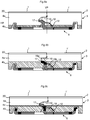
- Figures 2a - 2f show a first embodiment of the invention.
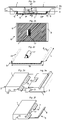
- Figure 2a show a cross section of a first and second panel 1, 1' each provided with a surface layer 2 comprising a transparent wear layer 20 which may be coated by a UV cured PU lacquer.
- the first and the second panels 1, 1' are preferably LVT panels.
- a decorative plastic foil 21 is attached to a core 3 and under the transparent layer 20.
- the core 3 that preferably comprises a thermosetting plastic material with a filler may have several core layers, which may have different density and hardness.
- the locking system comprises a tongue 10 at the second edge of the second panel 1', a tongue groove 9 at a first edge of the first panel and a clip 6, that preferably is formed by punching a metal sheet, for example a 0,3 - 0,6 mm aluminium or steel sheet.
- the clip 6 comprises a clip body 7 at a rear side of a first panel 1.
- the clip body comprises an inner part IP that extends inwardly from a first edge of the first panel and an outer part OP that extends outwardly from the first edge of the first panel 1.
- the clip 6 comprises a fixing element 16 located in a fixing groove 15 in the first panel 1 and a locking element 8 located in a locking groove 14 formed in an adjacent second panel 1' that lock the panel edges horizontally and prevents horizontal separation.
- the clip 6 comprises a locking protrusion 17 formed on the strip body 7 between the locking element 8 and the fixing element 16.
- the locking protrusion 17 projects vertically upwardly from the strip body and is located in a recess 18 formed in the lower lip 12 of the tongue groove 9.
- the recess 18 extends vertically from an upper to a lower part of the lower lip 12.
- the locking protrusion 17 is in this embodiment located such that it is displaced inwardly from the vertical plane VP.
- a part of the locking protrusion 17 extends inwardly into the tongue groove 9 and beyond the outer part of the tongue 10.
- An upper part of the locking protrusion 17 is preferably located above a horizontal plane HP that intersects the lower part of the tongue 10 and the upper part of the lower lip 12.
- the locking protrusion 17 connects the clip 6 vertically to the first panel 1 edge and prevents downward bending of the clip 6 when the edges of the first 1 and the second 1' panels are exposed to separation forces.
- the locking protrusion 17 prevents a displacement of the clip 6 inwardly such that the clip 6 is accurately fixed and positioned in a pre-determined position by the locking protrusion 17 and the fixing element 16.
- the clip 6 may be connected to the core 3 in a horizontal plane HP that is located above the lower lip 12 and to an edge part that is more rigid than an outer part of the lower lip.
- the whole vertical extension of the lower lip 12 and tongue groove 9 may be used to accomplish a strong connection without any essential negative effect on the vertical tongue 10 and tongue groove 9 connection since only a small part of the lower lip 12 will be partially removed when the recess 18 is formed.
- the upper contact surfaces between the tongue 10 and the upper lip 11 are unchanged and may provide an unchanged sealing against moisture penetration into the joint.
- the locking protrusion may be connected to an edge part that comprises sufficient material to allow a strong connection even when the panels are thin for example 3-4 mm and comprise a core 3 of flexible material, such as thermoplastic material mixed with a filler, which is a material composition generally used in LVT floors.
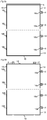
- Figure 2b is a top view of the clip 6.
- Figure 2c shows a clip 6 that has a length direction L along the edge and a width direction W perpendicular to the length.
- a clip with a length of about 3 cm and a width of about 2 cm may provide a locking strength that corresponds to a pulling force of about 200 N. 10 clips/m are sufficient to provide a locking strength on a long edge of about 2000 N.
- Figure 2d shows an edge section of the first panel 1 that comprises a recess 18 formed in the lower lip 12.
- Figure 2e shows the same edge section of the first panel 1 with the surface layer 2 pointing downwards and the recess 18 formed in the lower lip 12.
- Figure 2f shows a clip 6 connected to an edge section 1 of the first panel.
- the locking protrusion is located in a recess 18 formed in the lower lip 12.
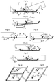
- FIG. 3a shows that the locking system may be locked with angling.
- the lower lip 12 comprises preferably a sliding surface 19 that guides the tongue 10 into the tongue groove 9 during angling but also during horizontal snapping.
- the sliding surface 19 and a part of the lower lip 12 are located above the outer part OP of the clip body 7.
- Figure 3b shows that the clip 6 may be connected with angling and pressing of the fixing element 16 with a pressing tool P into the fixing groove 15.
- the recess 18 is preferably formed by a vertically rotating tool T that cuts the edge as a saw blade.
- Figures 3c, 3d and 3e show that the clip 6 may be connected by a horizontal displacement and pressing against the fixing element 16 such that a bending of the fixing element 16 takes place.
- Figure 3f shows that the fixing element 16 may be pressed into the core 3 and the fixing groove 15 is formed by the fixing element 16.
- the fixing groove may be pre cut with a knife.
- Glue may also be used to connect the clip 6 to a panel edge. Glue may in some applications replace the fixing grove 15 and the fixing element 16.
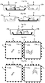
- Figure 3g shows that several clips 6a, 6b may be formed by punching a metal sheet and may be inserted after separation from a clip blank comprising several clips.
- Figure 3h shows that the clip 6 may have several locking protrusions 17a, 17b.
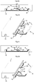
- Figures 4a - 4c show that the clip 6 may comprise guiding parts 22 having an upwardly extending sliding surface 19 that may facilitate the guiding of the tongue 10 into the tongue groove 9 during angling and/or horizontal snapping.
- the guiding part 22 may also be used to position the clip 6 horizontally against the lower lip 12.
- Figures 5a - 5d show that the recess 18 may be formed in an upper surface of the lower lip 12 and extend along a part of the lower lip.
- Figures 6a - 6c show that the recess 18 may be formed in a lower part of the tongue 10 as shown in figure 6c where the panel 1' is shown with the rear side pointing upwards.
- the locking protrusion 17 is in locked position connected into the tongue groove 9 and located in the recess 18 formed in the lower part of the tongue 10.
- Figures 7a and 7b show that the recess 18,18' may extend from the tongue 10 and to the locking groove 14 in order to accommodate the outer part OP of the clip 6 that extends beyond the upper edge of the panel 1.
- Figures 7a and 7b show that the clip 6 may be an extruded section, for example a plastic or aluminium section.
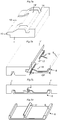
- Figures 8a and 8b show panels 1, 1' comprising a core 3 with an upper core layer 4a and a lower core layer 4b layer and wherein the locking protrusion 17 protrudes vertically beyond the lower layer 4b.
- Figure 8c shows that the core 3 may comprise a glass fibre layer 4c and the upper part of the locking protrusion may be located above such glass fibre layer 4c.
- Figure 9a shows a floor panel 1 comprising several clips 6 and recesses 18a on one of the long edges and several recesses 18b on the opposite long edge.
- the panel comprises a locking system on the short edges that is formed in one piece with the core.
- Figure 9b shows a locking system comprising clips 6 on long and short edges.
- Figures 10a - 10e show that all embodiment of this disclosure may be adapted such that a flooring system may comprise a first A panel and a second B panel comprising clips 6 on at least two opposite edges, a first edge 23a and a second edge 23b.
- the locking system is configured such that a first edge 23a of a first A panel may be locked to a second edge 23b and a first edge 23a of a second panel B.
- Figure 10a shows a cross section C1 - C1 of two adjacent edges 23a and 23b according to figure 10e . Both edges comprise a horizontal groove 9a and 9b and a lower lip 9a, 9b.
- the locking protrusion 17 is preferably located essentially above the lower lip 12a and the lower lip is preferably spaced horizontally from the vertical plane VP.
- Figure 10b show the cross section C2 - C2 in figure 10d and figure 10c shows the cross section C1 - C1 in locked position.
- the clips are offset along the adjacent edges such that they may be inserted between each other.
- Figure 10d shows that a first edge 23a of a first panel A may be locked to a second edge 23b of a second panel B.
- Figure 10e shows that a first edge 23a of the first panel A may also be connected to a first edge 23a of the second panel B.
- the above-described locking system may be used to lock all types of floor panels. Ceramic tiles may be installed with a space between the upper edges. This allows that the outer part of the lower lip 12 may be located at the vertical plane VP or may even protrude horizontally beyond the vertical plane VP and the upper part of the edge.
Description
- The disclosure generally relates to the field of mechanical locking systems for floor panels and building panels. The disclosure shows floorboards, locking systems and production methods.
- The present invention is particularly suitable for use in thin floating floors, which are formed of floor panels which are joined mechanically with a locking system preferably integrated with the floor panel, i.e. mounted at the factory, are made up of one or more upper layers of thermoplastic or thermosetting material or wood veneer, an intermediate core of wood-fibre-based material or plastic material and preferably a lower balancing layer on the rear side of the core. The invention can also be used for joining building panels which preferably contain a board material for instance wall panels, ceilings, furniture components and similar. Parts of the locking system may also be supplied as separate components, which may be connected to a panel during installation.
- The following description of prior-art technique, problems of known systems and objects and features of the invention will therefore, as a non-restrictive example, be aimed above all at this field of application and in particular at thin panels formed as rectangular floor panels with long and shorts edges intended to be mechanically joined to each other on both long and short edges.
- The long and short edges are mainly used to simplify the description of the invention. The panels may be square. It should be emphasised that the invention can be used in any floor panel on long and/or short edges and it may be combined with all types of known locking system that lock the panels in the horizontal and/or vertical direction.
- The following description of prior-art technique, problems of known systems and objects and features of the invention will, as a non-restrictive example, be aimed above all at floor panels and especially at thin resilient thermoplastic floor panels such as so called luxury vinyl tiles, generally referred to as LVT.
- LVT flooring usually comprises a transparent wear layer which may be coated by a UV cured PU lacquer, a decorative plastic foil and one or several core layers which generally are of different density and hardness. Relevant parts of this prior art description are also a part of the invention.
- Thin LVT floors with a thickness of 2-3 mm have traditionally been installed by gluing to the sub floor. Recently LVT floors have been introduced on the market that comprises a mechanical locking system, which allows a floating installation without glue. This facilitates installation and eliminates a lot of work to prepare the sub floor for gluing.
- Such LVT floors have generally a thickness of about 5 mm. This thickness is mainly required in order to form the locking system. The panel itself is strong and flexible and a thickness of about 3 mm would in many application be sufficient but can not be used since it is not possible to form a strong and cost efficient locking system in such thin floors.
- Such problems related to minimum thickness requirements due to the forming of locking systems are also applicable in other thin floor panels such as laminate floors and wood powder based floors where material and weight savings may be accomplished with lower thicknesses, preferably below 6 mm.
- Laminate flooring usually comprise a core of a 6-12 mm fibre board, a 0.2-0.8 mm thick upper decorative surface layer of laminate and a 0.1-0.6 mm thick lower balancing layer of laminate, plastic, paper or like material. A laminate surface comprises melamine-impregnated paper. The most common core material is fibreboard with high density and good stability usually called HDF - High Density Fibreboard. Sometimes also MDF - Medium Density Fibreboard - is used as core.
- Laminate floor panels of this type have been joined mechanically by means of so-called mechanical locking systems. These systems comprise locking means, which lock the panels horizontally and vertically. The mechanical locking systems are usually formed by machining of the core of the panel. Alternatively, parts of the locking system can be formed of a separate material, for instance aluminium or HDF, which are integrated with the floor panel, i.e. joined with the floor panel in connection with the manufacture thereof.
- The main advantages of floating floors with mechanical locking systems are that they are easy to install. They can also easily be taken up again and used once more at a different location.
- In the following text, the visible surface of the installed floor panel is called "front side", while the opposite side of the floor panel, facing the sub floor, is called "rear side". The edge between the front and rear side is called "joint edge". By "horizontal plane" is meant a plane, which extends parallel to the front side. Immediately juxtaposed upper parts of two adjacent joint edges of two joined floor panels together define a "vertical plane" perpendicular to the horizontal plane. By "vertical locking" is meant locking parallel to the vertical plane. By "horizontal locking" is meant locking parallel to the horizontal plane.
- By "up" is meant towards the front side, by "down" towards the rear side, by "inwardly" mainly horizontally towards an inner and centre part of the panel and by "outwardly" mainly horizontally away from the centre part of the panel.
- For mechanical joining of long edges as well as short edges in the vertical and horizontal direction perpendicular to the edges several methods may be used. One of the most used methods is the angle-snap method. The long edges are installed by angling. The short edges are locked by horizontal snapping. The vertical connection is generally a tongue and a groove and the horizontal connection is a strip with a locking element that cooperates with a locking groove in the adjacent edge.
- Similar locking systems may also be produced with a rigid strip and they are connected with an angling-angling method where both short and long edges are angled into a locked position.
- Advanced so-called fold down locking systems with a separate and flexible tongue on the short edges have been introduced where both the long and short edges are locked with an angling action.
- It is known that a locking strip may be formed of a separate material such as aluminium and that such strip may be clamped in undercut grooves. Such systems are described in
WO94/26999 -
WO 99/66152 - It is known from
CN 201588375 that clips may be used to accomplish horizontal and vertical locking. Such clips may provide cost advantages over a locking strip that extends along the whole edge. A disadvantage is that a considerable part of the edge between the clips is not locked vertically and the edges will move vertically when exposed to high load especially if the floor panels are thin and flexible. -
US 2001/0010139 A1 shows a locking system similar to embodiments shown inWO 94/26999 - It is also known from
WO 2013/025165 that a tongue and a groove formed in one piece with the core may be used for vertical locking and several strip parts spaced form each other may be attached to an edge in order to obtain horizontal locking. A disadvantage is that such locking system are not suitable for thin floors since the strip part is connected in a separate groove that extend along the whole edge and that is located under the lower part of the tongue. The connection of the strip part is not sufficient to prevent backwards bending of the strip body and edge separation when the edges are exposed to pulling forces. This is a disadvantage in thin laminate floors and floors with a rather soft core such as LVT floors. -
US 2009/056339 A1 discloses a retaining element for retaining a heat shield element on a support structure. The retaining element comprises at least one fixing section adapted to fix it to the support structure and at least one retaining section adapted to engage with an engaging groove present on a periphery of the heat shield element. A projection is arranged on the retaining element in such a manner that it projects in the direction of the heat shield element when retaining a heat shield element. - It would be an advantage if separate clips that comprise a stronger material than the core may be used to accomplish a horizontal locking in thin floors and if such horizontal locking may be combined with a vertical locking comprising a tongue and a grove that extends along the whole edge and is made in one piece with the core.
- An overall objective of the present invention is to provide an improved and more cost efficient locking system for primarily adjacent long edges of thin and flexible floor panels that may be locked to each with angling.
- A first specific objective is to provide a locking system for thin flooring comprising a tongue and groove for vertical connection and a separate clip that may be attached to the panel edge and provide a strong locking in panels with a thin and flexible core.
- A second specific objective, not claimed in the present invention, is to provide a flooring system comprising two types of panels that may be locked in a more flexible way in order to allow installation of advanced floor patterns.
- The above objects may be achieved by embodiments.
- According to a first aspect of the invention building panels are provided with a locking system comprising a tongue at a second edge of a second panel. The tongue is configured to cooperate with a tongue groove at a first edge of a first panel for locking in a vertical direction. The tongue groove comprises an upper lip and a lower lip. The locking system further comprises one or more clips attached to the first edge and a downwardly open locking groove formed at the second edge. Each clip comprises an upwardly extending locking element, which is configured to cooperate with the locking groove for locking the first edge and the second edge in a horizontal direction. The clip comprises a clip body at a rear side of the first panel. Said clip body is provided with an inner part, which extends inwardly from the first edge and an outer part, which extends outwardly from said first edge. The inner strip part comprises a fixing element that cooperates with a downwardly open fixing groove, formed on the rear side of the first panel, for locking the clip to the first edge in a horizontal direction. The clip comprises a locking protrusion that protrudes upwardly from the clip body. The locking protrusion is configured to lock the clip to the first edge in a vertical direction. The lower lip or the tongue comprises a recess and the locking protrusion is in a locked position positioned in the recess. The locking protrusion is spaced horizontally inwardly in the tongue groove beyond the outer tip of the tongue.
- The locking protrusion may have a part that is located in the tongue groove.
- A part of the locking protrusion may be located below the tongue.
- The locking protrusion may comprise a first part that extends upwardly from the clip body and a second part that extends inwardly into the tongue groove.
- The locking protrusion may be located inwardly and spaced horizontally from the vertical plane.
- The panel may comprise a core of plastic material.
- The panel may comprise a surface of thermoplastic material.
- The panel may comprise a core with an upper core layer and a lower core layer and the locking protrusion may protrude vertically beyond the lower core layer.
- According to a second aspect, not presently claimed, a flooring system is provided comprising a first panel and a second panel provided with a locking system comprising clips. Said clips being arranged at a first edge and at an opposite second edge of the first and the second panel. The locking system is configured to lock the first edge of the first panel to the second edge of the second panel in a horizontal and a vertical direction.
- The first edge and the second edge may each comprises a horizontal groove comprising a lower lip.
- Each clip may comprise a vertically extending locking protrusion with an upper part that is located essentially above the lower lip of the first and the second panel, respectively.
- Each lower lip may be spaced horizontally and inwardly from an upper part of the edge.
- The disclosure will in the following be described in connection to exemplary embodiments and in greater detail with reference to the appended exemplary drawings, wherein:
- Figs 1a-f
- illustrates locking systems according to known technology.
- Figs 2a-f
- illustrate a clip that may be used to lock thin floor panels according to an embodiment of the invention.
- Figs 3a-h
- illustrate clips and a production methods to connect a clip to an edge according to embodiments of the invention.
- Figs 4a-c
- illustrate a locking system according to an embodiment of the invention.
- Figs 5a-d
- illustrate a locking system according to an embodiment of the invention.
- Figs 6a-c
- illustrate a locking system according to an embodiment of the invention.
- Figs 7a-d
- illustrate a locking system according to an embodiment of the invention.
- Figs 8a-c
- illustrate a locking system and a LVT floor panel with a core comprising several layers according to an embodiment of the invention.
- Figs 9a-b
- illustrate panels with clips on long and short edges according to an embodiment of the invention.
- Figs 10a -10e
- illustrate A and B panels comprising clips on both adjacent edges.
-
Figures 1a-1f show known locking systems.Figure 1a shows a conventional locking system formed in one piece with thecore 5 and configured to lock with angling. Thefloor panel 1, 1' comprises a locking system that has atongue 10 and atongue groove 9 that lock vertically and astrip 5 with alocking element 8 that cooperates with a lockinggroove 14 and locks the edges horizontally. -
Figure 1b and 1c shows a locking system with aseparate strip 5 that comprises a lockingprotrusion 17 connected to alower lip 12 of thetongue groove 9 that protrudes beyond a vertical plane VP. The lockingprotrusion 17 is located under a horizontal plane HP that intersects the lower part of thetongue 10. Such locking system may not provide sufficient locking strength in thin and flexible core material since thelower lip 12 and the outer part of thestrip 5 will bend downwards when the edges are exposed to pulling forces and thelocking element 8 will slide out from the lockinggroove 14. -
Figures 1d - 1f show similar locking systems comprising a plastic ormetal clip 6 with a lockingprotrusion 17 connected to an upper part of thelower lip 12 which is located under thetongue 10 and under the cooperating locking surfaces between the tongue and thelower lip 12. The clip is connected to an outer part of alower lip 12 that is positioned beyond the upper lip and beyond the vertical plane VP. - To facilitate understanding of the described invention, several locking systems in the figures are shown schematically. It should be emphasised that improved or different functions can be achieved using combinations of the preferred embodiments.
- All embodiments may be used separately or in combinations. Angles, dimensions, rounded parts, spaces between surfaces etc. are only examples and may be adjusted within the basic principles of the invention.
-
Figures 2a - 2f show a first embodiment of the invention. -
Figure 2a show a cross section of a first andsecond panel 1, 1' each provided with asurface layer 2 comprising atransparent wear layer 20 which may be coated by a UV cured PU lacquer. The first and thesecond panels 1, 1' are preferably LVT panels. Adecorative plastic foil 21 is attached to acore 3 and under thetransparent layer 20. Thecore 3 that preferably comprises a thermosetting plastic material with a filler may have several core layers, which may have different density and hardness. The locking system comprises atongue 10 at the second edge of the second panel 1', atongue groove 9 at a first edge of the first panel and aclip 6, that preferably is formed by punching a metal sheet, for example a 0,3 - 0,6 mm aluminium or steel sheet. Theclip 6 comprises aclip body 7 at a rear side of afirst panel 1. The clip body comprises an inner part IP that extends inwardly from a first edge of the first panel and an outer part OP that extends outwardly from the first edge of thefirst panel 1. - The
clip 6 comprises a fixingelement 16 located in a fixinggroove 15 in thefirst panel 1 and alocking element 8 located in a lockinggroove 14 formed in an adjacent second panel 1' that lock the panel edges horizontally and prevents horizontal separation. Theclip 6 comprises a lockingprotrusion 17 formed on thestrip body 7 between the lockingelement 8 and the fixingelement 16. The lockingprotrusion 17 projects vertically upwardly from the strip body and is located in arecess 18 formed in thelower lip 12 of thetongue groove 9. Therecess 18 extends vertically from an upper to a lower part of thelower lip 12. The lockingprotrusion 17 is in this embodiment located such that it is displaced inwardly from the vertical plane VP. A part of the lockingprotrusion 17 extends inwardly into thetongue groove 9 and beyond the outer part of thetongue 10. An upper part of the lockingprotrusion 17 is preferably located above a horizontal plane HP that intersects the lower part of thetongue 10 and the upper part of thelower lip 12. The lockingprotrusion 17 connects theclip 6 vertically to thefirst panel 1 edge and prevents downward bending of theclip 6 when the edges of the first 1 and the second 1' panels are exposed to separation forces. The lockingprotrusion 17 prevents a displacement of theclip 6 inwardly such that theclip 6 is accurately fixed and positioned in a pre-determined position by the lockingprotrusion 17 and the fixingelement 16. - An advantage is that the
clip 6 may be connected to thecore 3 in a horizontal plane HP that is located above thelower lip 12 and to an edge part that is more rigid than an outer part of the lower lip. The whole vertical extension of thelower lip 12 andtongue groove 9 may be used to accomplish a strong connection without any essential negative effect on thevertical tongue 10 andtongue groove 9 connection since only a small part of thelower lip 12 will be partially removed when therecess 18 is formed. The upper contact surfaces between thetongue 10 and theupper lip 11 are unchanged and may provide an unchanged sealing against moisture penetration into the joint. The locking protrusion may be connected to an edge part that comprises sufficient material to allow a strong connection even when the panels are thin for example 3-4 mm and comprise acore 3 of flexible material, such as thermoplastic material mixed with a filler, which is a material composition generally used in LVT floors. -
Figure 2b is a top view of theclip 6.Figure 2c shows aclip 6 that has a length direction L along the edge and a width direction W perpendicular to the length. A clip with a length of about 3 cm and a width of about 2 cm may provide a locking strength that corresponds to a pulling force of about 200 N. 10 clips/m are sufficient to provide a locking strength on a long edge of about 2000 N. -
Figure 2d shows an edge section of thefirst panel 1 that comprises arecess 18 formed in thelower lip 12.Figure 2e shows the same edge section of thefirst panel 1 with thesurface layer 2 pointing downwards and therecess 18 formed in thelower lip 12. -
Figure 2f shows aclip 6 connected to anedge section 1 of the first panel. The locking protrusion is located in arecess 18 formed in thelower lip 12. -
Figure 3a shows that the locking system may be locked with angling. Thelower lip 12 comprises preferably a slidingsurface 19 that guides thetongue 10 into thetongue groove 9 during angling but also during horizontal snapping. The slidingsurface 19 and a part of thelower lip 12 are located above the outer part OP of theclip body 7. -
Figure 3b shows that theclip 6 may be connected with angling and pressing of the fixingelement 16 with a pressing tool P into the fixinggroove 15. Therecess 18 is preferably formed by a vertically rotating tool T that cuts the edge as a saw blade. -
Figures 3c, 3d and 3e show that theclip 6 may be connected by a horizontal displacement and pressing against the fixingelement 16 such that a bending of the fixingelement 16 takes place. -
Figure 3f shows that the fixingelement 16 may be pressed into thecore 3 and the fixinggroove 15 is formed by the fixingelement 16. The fixing groove may be pre cut with a knife. Glue may also be used to connect theclip 6 to a panel edge. Glue may in some applications replace the fixinggrove 15 and the fixingelement 16. -
Figure 3g shows thatseveral clips Figure 3h shows that theclip 6 may have several lockingprotrusions -
Figures 4a - 4c show that theclip 6 may comprise guidingparts 22 having an upwardly extending slidingsurface 19 that may facilitate the guiding of thetongue 10 into thetongue groove 9 during angling and/or horizontal snapping. The guidingpart 22 may also be used to position theclip 6 horizontally against thelower lip 12. -
Figures 5a - 5d show that therecess 18 may be formed in an upper surface of thelower lip 12 and extend along a part of the lower lip. -
Figures 6a - 6c show that therecess 18 may be formed in a lower part of thetongue 10 as shown infigure 6c where the panel 1' is shown with the rear side pointing upwards. The lockingprotrusion 17 is in locked position connected into thetongue groove 9 and located in therecess 18 formed in the lower part of thetongue 10. -
Figures 7a and 7b show that therecess 18,18' may extend from thetongue 10 and to the lockinggroove 14 in order to accommodate the outer part OP of theclip 6 that extends beyond the upper edge of thepanel 1.Figures 7a and 7b show that theclip 6 may be an extruded section, for example a plastic or aluminium section. -
Figures 8a and 8b show panels 1, 1' comprising acore 3 with anupper core layer 4a and alower core layer 4b layer and wherein the lockingprotrusion 17 protrudes vertically beyond thelower layer 4b.Figure 8c shows that thecore 3 may comprise aglass fibre layer 4c and the upper part of the locking protrusion may be located above suchglass fibre layer 4c. -
Figure 9a shows afloor panel 1 comprisingseveral clips 6 and recesses 18a on one of the long edges andseveral recesses 18b on the opposite long edge. The panel comprises a locking system on the short edges that is formed in one piece with the core.Figure 9b shows a lockingsystem comprising clips 6 on long and short edges. -
Figures 10a - 10e show that all embodiment of this disclosure may be adapted such that a flooring system may comprise a first A panel and a second Bpanel comprising clips 6 on at least two opposite edges, afirst edge 23a and asecond edge 23b. The locking system is configured such that afirst edge 23a of a first A panel may be locked to asecond edge 23b and afirst edge 23a of a second panel B. -
Figure 10a shows a cross section C1 - C1 of twoadjacent edges figure 10e . Both edges comprise ahorizontal groove lower lip protrusion 17 is preferably located essentially above thelower lip 12a and the lower lip is preferably spaced horizontally from the vertical plane VP. -
Figure 10b show the cross section C2 - C2 infigure 10d and figure 10c shows the cross section C1 - C1 in locked position. - The clips are offset along the adjacent edges such that they may be inserted between each other.
-
Figure 10d shows that afirst edge 23a of a first panel A may be locked to asecond edge 23b of a second panel B.Figure 10e shows that afirst edge 23a of the first panel A may also be connected to afirst edge 23a of the second panel B. - The above-described locking system may be used to lock all types of floor panels. Ceramic tiles may be installed with a space between the upper edges. This allows that the outer part of the
lower lip 12 may be located at the vertical plane VP or may even protrude horizontally beyond the vertical plane VP and the upper part of the edge.
Claims (15)
- Building panels provided with a locking system comprising a tongue (10) at a second edge of a second panel (1'), the tongue being configured to cooperate with a tongue groove (9) at a first edge of a first panel (1) for locking in a vertical direction, the tongue groove (9) comprising an upper lip (11) and a lower lip (12), the locking system further comprising one or more clips (6) attached to the first edge and a downwardly open locking groove (14) formed at the second edge, wherein each clip (6) comprises an upwardly extending locking element (8), which is configured to cooperate with the locking groove (14) for locking the first edge and the second edge in a horizontal direction, wherein:the clip (6) comprises a clip body (7) at a rear side of the first panel (1), said clip body (7) being provided with an inner part (IP), which extends inwardly from the first edge, and an outer part (OP), which extends outwardly from said first edge,the inner part (IP) comprises a fixing element (16) that cooperates with a downwardly open fixing groove (15), formed on the rear side of the first panel (1), for locking the clip (6) to the first edge in a horizontal direction,the clip (6) comprises a locking protrusion (17), which protrudes upwardly from the clip body (7), said locking protrusion (17) being configured to lock the clip (6) to the first edge in a vertical direction,the lower lip (12) or the tongue (10) comprises a recess (18), andthe locking protrusion (17) is in a locked position positioned in the recess (18),characterized in that said locking protrusion (17) is spaced horizontally inwardly in the tongue groove (9) beyond the outer tip of the tongue (10).
- The building panels as claimed in claim 1, wherein a part of the locking protrusion (17) is located in the tongue groove (9).
- The building panels as claimed in claim 1 or 2, wherein a part of the locking protrusion (17) is located below the tongue (10).
- The building panels as claimed in any one of the preceding claims 1-3, wherein the locking protrusion (17) comprises a first part (17a) that extends upwardly from the clip body (7) and a second part (17b) that extends inwardly into the tongue groove (9).
- The building panels as claimed in any one of the preceding claims 1-4, wherein the locking protrusion (17) is located inwardly and spaced horizontally from a vertical plane defined by immediately juxtaposed upper parts of said first edge and said second edge, the vertical plane being provided perpendicularly to a horizontal plane extending parallel to a front side of the first panel and the second panel.
- The building panels as claimed in any one of the claims 1-5, wherein the first panel and the second panel comprise a core of plastic material.
- The building panels as claimed in any one of the preceding claims 1-6, wherein the first panel and the second panel comprise a surface of thermoplastic material.
- The building panels as claimed in any one of the preceding claims 1-7, wherein the first panel and the second panel comprise a core (3) with an upper core layer (4a) and a lower core layer (4b) and wherein the locking protrusion (17) protrudes vertically beyond the lower core layer (4b).
- The building panels as claimed in any one of the preceding claims 1-8, wherein the lower lip (12) comprises said recess (18), and wherein the recess (18) extends vertically from an upper to a lower part of the lower lip (12).
- The building panels as claimed in any one of the preceding claims 1-9, wherein the lower lip (12) comprises said recess (18), wherein the locking system is configured to be locked with angling, and wherein the lower lip (12) comprises a sliding surface (19) that is configured to guide the tongue (10) into the tongue groove (9) during angling.
- The building panels as claimed in any one of the preceding claims 1-10, wherein the lower lip (12) comprises said recess (18), and wherein the clip (6) comprises guiding parts (22) having an upwardly extending sliding surface (19).
- The building panels as claimed in any one of the preceding claims 1-11, wherein the lower lip (12) comprises said recess (18), and wherein the recess (18) extends along a part of the lower lip (12).
- The building panels as claimed in any one of the preceding claims 1-12, wherein the locking protrusion (17) is formed on the strip body (7) between the locking element (8) and the fixing element (16).
- The building panels as claimed in any one of claims 1-8, wherein the tongue (10) comprises said recess, and wherein the recess (18, 18') extends from the tongue (10) to the locking groove (14) for accommodating the outer part (OP) of the clip (6).
- The building panels as claimed in any one of claims 1-14, wherein the clip (6) has several locking protrusions (17a, 17b).
Priority Applications (1)
| Application Number | Priority Date | Filing Date | Title |
|---|---|---|---|
| EP19167121.3A EP3527743B1 (en) | 2013-10-25 | 2014-10-24 | Mechanical locking system for floor panels |
Applications Claiming Priority (2)
| Application Number | Priority Date | Filing Date | Title |
|---|---|---|---|
| SE1351273 | 2013-10-25 | ||
| PCT/SE2014/051251 WO2015060780A1 (en) | 2013-10-25 | 2014-10-24 | Mechanical locking system for floor panels |
Related Child Applications (1)
| Application Number | Title | Priority Date | Filing Date |
|---|---|---|---|
| EP19167121.3A Division EP3527743B1 (en) | 2013-10-25 | 2014-10-24 | Mechanical locking system for floor panels |
Publications (3)
| Publication Number | Publication Date |
|---|---|
| EP3060728A1 EP3060728A1 (en) | 2016-08-31 |
| EP3060728A4 EP3060728A4 (en) | 2017-06-21 |
| EP3060728B1 true EP3060728B1 (en) | 2019-04-10 |
Family
ID=52993249
Family Applications (2)
| Application Number | Title | Priority Date | Filing Date |
|---|---|---|---|
| EP19167121.3A Active EP3527743B1 (en) | 2013-10-25 | 2014-10-24 | Mechanical locking system for floor panels |
| EP14856454.5A Active EP3060728B1 (en) | 2013-10-25 | 2014-10-24 | Mechanical locking system for floor panels |
Family Applications Before (1)
| Application Number | Title | Priority Date | Filing Date |
|---|---|---|---|
| EP19167121.3A Active EP3527743B1 (en) | 2013-10-25 | 2014-10-24 | Mechanical locking system for floor panels |
Country Status (9)
| Country | Link |
|---|---|
| US (3) | US10041258B2 (en) |
| EP (2) | EP3527743B1 (en) |
| KR (1) | KR102314032B1 (en) |
| CN (1) | CN105658883B (en) |
| CA (1) | CA2926336C (en) |
| ES (1) | ES2728351T3 (en) |
| PT (1) | PT3060728T (en) |
| RU (1) | RU2662745C2 (en) |
| WO (1) | WO2015060780A1 (en) |
Families Citing this family (21)
| Publication number | Priority date | Publication date | Assignee | Title |
|---|---|---|---|---|
| US9725912B2 (en) * | 2011-07-11 | 2017-08-08 | Ceraloc Innovation Ab | Mechanical locking system for floor panels |
| US8763340B2 (en) | 2011-08-15 | 2014-07-01 | Valinge Flooring Technology Ab | Mechanical locking system for floor panels |
| PT3613919T (en) | 2013-06-27 | 2023-02-13 | Vaelinge Innovation Ab | Building panel with a mechanical locking system |
| US10060139B2 (en) | 2013-07-09 | 2018-08-28 | Ceraloc Innovation Ab | Mechanical locking system for floor panels |
| CA2926336C (en) | 2013-10-25 | 2022-07-05 | Floor Iptech Ab | Mechanical locking system for floor panels |
| CN107002412B (en) * | 2014-09-04 | 2020-09-18 | Qlx私人有限公司 | Floor paving module |
| CN107002411B (en) | 2014-11-27 | 2020-06-16 | 瓦林格创新股份有限公司 | Mechanical locking system for floor panels |
| HUE062077T2 (en) * | 2016-01-15 | 2023-09-28 | Beaulieu Int Group Nv | Set of panels with a locking strip, method for manufacturing such set of panels, and assembly of the panels |
| US10557265B2 (en) * | 2016-04-26 | 2020-02-11 | Embassy Ceiling Inc. | Clip for suspended ceiling members |
| EP3807475B1 (en) | 2018-06-13 | 2023-11-15 | Ceraloc Innovation AB | A flooring system provided with a connecting system and an associated connecting device |
| NL2021884B1 (en) * | 2018-10-26 | 2020-05-13 | I4F Licensing Nv | Panel, in particular a floor panel or wall panel |
| BE1026806B1 (en) * | 2018-11-27 | 2020-06-30 | Flooring Ind Ltd Sarl | Panel and method of manufacturing such panel |
| PL3670783T3 (en) * | 2018-12-21 | 2021-11-02 | SWISS KRONO Tec AG | Mounting clip for floating mounting of wall and ceiling panels |
| US11060302B2 (en) | 2019-01-10 | 2021-07-13 | Valinge Innovation Ab | Unlocking system for panels |
| IT201900003627A1 (en) * | 2019-03-13 | 2020-09-13 | Parchettificio Garbelotto S R L | JOINT FOR SLAT FLOORS |
| DE102019120549A1 (en) * | 2019-07-30 | 2021-02-04 | CliXBond GmbH | Method for producing a composite profile, profile system and composite component |
| EP3798384A1 (en) * | 2019-09-24 | 2021-03-31 | Välinge Innovation AB | Building panel |
| CA3154929A1 (en) * | 2019-09-24 | 2021-04-01 | Valinge Innovation Ab | Building panel |
| EP3798385A1 (en) * | 2019-09-24 | 2021-03-31 | Välinge Innovation AB | Building panel |
| WO2021087255A1 (en) | 2019-10-31 | 2021-05-06 | Certainteed Llc | Attachment clips for building surface panels and building surface panel system |
| US11773600B2 (en) * | 2021-07-23 | 2023-10-03 | Bath Systems, LLC | Wall paneling system |
Family Cites Families (169)
| Publication number | Priority date | Publication date | Assignee | Title |
|---|---|---|---|---|
| US108068A (en) | 1870-10-04 | Improvement in tiles for roofing | ||
| US87853A (en) | 1869-03-16 | Improved mosaic floor | ||
| US274354A (en) | 1883-03-20 | Carthy | ||
| US213740A (en) | 1879-04-01 | Improvement in wooden roofs | ||
| DE138992C (en) | 1901-07-20 | 1903-02-26 | Gebhard Dietrich | MACHINE FOR THE MANUFACTURE OF WOODEN MOSAIC PANELS FROM WOODEN BLOCKS CONNECTED BY SPRINGS |
| DE142293C (en) | 1902-07-11 | 1903-07-04 | A. Wächter-Leuzinger | METHOD OF MANUFACTURING BASE PLATES FROM PRISM PIECES THAT ARE HELD TOGETHER BY CROSSING CONNECTING BARS |
| US876693A (en) | 1907-01-08 | 1908-01-14 | George H Coldwell | Floor-jack. |
| US1898364A (en) * | 1930-02-24 | 1933-02-21 | George S Gynn | Flooring construction |
| US2110728A (en) | 1933-01-03 | 1938-03-08 | Certain Teed Prod Corp | Construction material and method of making same |
| US2430200A (en) | 1944-11-18 | 1947-11-04 | Nina Mae Wilson | Lock joint |
| US2889016A (en) | 1955-04-13 | 1959-06-02 | Warren Jack | Chassis construction strip and a chassis |
| US3099110A (en) | 1957-09-17 | 1963-07-30 | Dur O Wal National Inc | Control joint |
| US3147522A (en) | 1960-06-01 | 1964-09-08 | Schumm Erich | Flexible tie |
| US3187612A (en) | 1962-12-18 | 1965-06-08 | Robert W Hervey | Method for simultaneously cutting overlapping boards from a single sheet |
| SE0002342L (en) | 2000-06-22 | 2001-07-16 | Tarkett Sommer Ab | Floor board with connecting means |
| DE2021503A1 (en) | 1970-05-02 | 1971-11-25 | Freudenberg Carl Fa | Floor panels and methods of joining them |
| DE2159042C3 (en) | 1971-11-29 | 1974-04-18 | Heinrich 6700 Ludwigshafen Hebgen | Insulating board, in particular made of rigid plastic foam |
| US3939546A (en) | 1974-08-07 | 1976-02-24 | Hernandez Ralph G | Tool for setting jointed flooring panels |
| US4169688A (en) | 1976-03-15 | 1979-10-02 | Sato Toshio | Artificial skating-rink floor |
| US4426820A (en) | 1979-04-24 | 1984-01-24 | Heinz Terbrack | Panel for a composite surface and a method of assembling same |
| US4447172A (en) | 1982-03-18 | 1984-05-08 | Structural Accessories, Inc. | Roadway expansion joint and seal |
| DE3310281A1 (en) | 1983-03-22 | 1984-10-04 | Günter 5902 Netphen Werthebach | Slab for wall and floor structure |
| DK149498C (en) | 1983-04-07 | 1986-12-01 | Inter Ikea As | CLOTHING OF BREADS FOR EX. FLOORS OR PANELS |
| US4512131A (en) | 1983-10-03 | 1985-04-23 | Laramore Larry W | Plank-type building system |
| DE3343601A1 (en) | 1983-12-02 | 1985-06-13 | Bütec Gesellschaft für bühnentechnische Einrichtungen mbH, 4010 Hilden | Joining arrangement for rectangular boards |
| US4819932A (en) | 1986-02-28 | 1989-04-11 | Trotter Jr Phil | Aerobic exercise floor system |
| US5135597A (en) | 1988-06-23 | 1992-08-04 | Weyerhaeuser Company | Process for remanufacturing wood boards |
| US5272850A (en) | 1991-05-06 | 1993-12-28 | Icon, Incorporated | Panel connector |
| DE4215273C2 (en) | 1992-05-09 | 1996-01-25 | Dietmar Groeger | Covering for covering floor, wall and / or ceiling surfaces, in particular in the manner of a belt floor |
| US5295341A (en) | 1992-07-10 | 1994-03-22 | Nikken Seattle, Inc. | Snap-together flooring system |
| JP2550466B2 (en) | 1992-11-02 | 1996-11-06 | 大建工業株式会社 | Floor material |
| DE4242530C2 (en) | 1992-12-16 | 1996-09-12 | Walter Friedl | Building element for walls, ceilings or roofs of buildings |
| SE9301595L (en) | 1993-05-10 | 1994-10-17 | Tony Pervan | Grout for thin liquid hard floors |
| SE509060C2 (en) | 1996-12-05 | 1998-11-30 | Valinge Aluminium Ab | Method for manufacturing building board such as a floorboard |
| US5435610A (en) | 1994-03-18 | 1995-07-25 | Charles Taylor | Subfloor panel driving device and method |
| US5485702A (en) | 1994-03-25 | 1996-01-23 | Glenn Sholton | Mortarless glass block assembly |
| SE9500810D0 (en) | 1995-03-07 | 1995-03-07 | Perstorp Flooring Ab | Floor tile |
| US5577357A (en) | 1995-07-10 | 1996-11-26 | Civelli; Ken | Half log siding mounting system |
| BR7502683U (en) | 1995-11-24 | 1996-04-09 | Jacob Abrahams | Constructive arrangements in joints of strips for laminate floors or ceilings |
| BE1010487A6 (en) | 1996-06-11 | 1998-10-06 | Unilin Beheer Bv | FLOOR COATING CONSISTING OF HARD FLOOR PANELS AND METHOD FOR MANUFACTURING SUCH FLOOR PANELS. |
| US5950389A (en) | 1996-07-02 | 1999-09-14 | Porter; William H. | Splines for joining panels |
| US6203653B1 (en) | 1996-09-18 | 2001-03-20 | Marc A. Seidner | Method of making engineered mouldings |
| US6808777B2 (en) | 1996-11-08 | 2004-10-26 | Ab Golvabia | Flooring |
| SE507737C2 (en) | 1996-11-08 | 1998-07-06 | Golvabia Ab | Device for joining of flooring material |
| SE509059C2 (en) | 1996-12-05 | 1998-11-30 | Valinge Aluminium Ab | Method and equipment for making a building board, such as a floorboard |
| US5845548A (en) | 1996-12-06 | 1998-12-08 | Nelson; Jerome S. C. | Flooring tools |
| US6295779B1 (en) | 1997-11-26 | 2001-10-02 | Fred C. Canfield | Composite frame member and method of making the same |
| US5970675A (en) | 1997-12-05 | 1999-10-26 | James D. Wright | Modular panel assembly |
| US7386963B2 (en) | 1998-06-03 | 2008-06-17 | Valinge Innovation Ab | Locking system and flooring board |
| SE512313C2 (en) | 1998-06-03 | 2000-02-28 | Valinge Aluminium Ab | Locking system and floorboard |
| SE512290C2 (en) | 1998-06-03 | 2000-02-28 | Valinge Aluminium Ab | Locking system for mechanical joining of floorboards and floorboard provided with the locking system |
| SE513189C2 (en) | 1998-10-06 | 2000-07-24 | Perstorp Flooring Ab | Vertically mountable floor covering material comprising sheet-shaped floor elements which are joined together by means of separate joint profiles |
| SE514645C2 (en) | 1998-10-06 | 2001-03-26 | Perstorp Flooring Ab | Floor covering material comprising disc-shaped floor elements intended to be joined by separate joint profiles |
| SE515789C2 (en) | 1999-02-10 | 2001-10-08 | Perstorp Flooring Ab | Floor covering material comprising floor elements which are intended to be joined vertically |
| US6254301B1 (en) | 1999-01-29 | 2001-07-03 | J. Melvon Hatch | Thermoset resin-fiber composites, woodworking dowels and other articles of manufacture made therefrom, and methods |
| IL129834A (en) | 1999-05-06 | 2001-09-13 | Ackerstein Ind Ltd | Ground surface cover system with flexible interlocking joint for erosion control |
| US6358352B1 (en) | 1999-06-25 | 2002-03-19 | Wyoming Sawmills, Inc. | Method for creating higher grade wood products from lower grade lumber |
| SE517009C2 (en) | 1999-07-05 | 2002-04-02 | Perstorp Flooring Ab | Floor element with controls |
| AT413227B (en) | 1999-07-23 | 2005-12-15 | Kaindl M | PANEL OR LUMINOUS COMPONENTS OR ARRANGEMENT WITH SUCH COMPONENTS AND CLAMPS HIEFÜR |
| US6449918B1 (en) | 1999-11-08 | 2002-09-17 | Premark Rwp Holdings, Inc. | Multipanel floor system panel connector with seal |
| US7614197B2 (en) | 1999-11-08 | 2009-11-10 | Premark Rwp Holdings, Inc. | Laminate flooring |
| AU4743800A (en) | 1999-12-23 | 2001-07-09 | Hamberger Industriewerke Gmbh | Joint |
| US6332733B1 (en) | 1999-12-23 | 2001-12-25 | Hamberger Industriewerke Gmbh | Joint |
| DE19963203A1 (en) | 1999-12-27 | 2001-09-20 | Kunnemeyer Hornitex | Plate section, especially a laminate floor plate, consists of a lignocellulose containing material with a coated surface and an edge impregnation agent |
| DE10001076C1 (en) * | 2000-01-13 | 2001-10-04 | Huelsta Werke Huels Kg | Panel element to construct floor covering; has groove and spring on opposite longitudinal sides and has groove and tongue on opposite end faces, to connect and secure adjacent panel elements |
| EP1120515A1 (en) | 2000-01-27 | 2001-08-01 | Triax N.V. | A combined set comprising a locking member and at least two building panels |
| US20010010139A1 (en) * | 2000-01-27 | 2001-08-02 | Johan De Kerpel | Combined set comprising a locking member and at least two building panels |
| SE518184C2 (en) | 2000-03-31 | 2002-09-03 | Perstorp Flooring Ab | Floor covering material comprising disc-shaped floor elements which are joined together by means of interconnecting means |
| US6363677B1 (en) | 2000-04-10 | 2002-04-02 | Mannington Mills, Inc. | Surface covering system and methods of installing same |
| FR2810060A1 (en) | 2000-06-08 | 2001-12-14 | Ykk France | Wooden floor paneling, for parquet floor, has elastic strip with lateral flanges forming stop faces for recessed surfaces on panels |
| DE10031639C2 (en) | 2000-06-29 | 2002-08-14 | Hw Ind Gmbh & Co Kg | Floor plate |
| SE0003091D0 (en) | 2000-07-07 | 2000-09-01 | Ericsson Telefon Ab L M | Communication system |
| US6339908B1 (en) | 2000-07-21 | 2002-01-22 | Fu-Ming Chuang | Wood floor board assembly |
| US6576079B1 (en) | 2000-09-28 | 2003-06-10 | Richard H. Kai | Wooden tiles and method for making the same |
| US6851241B2 (en) * | 2001-01-12 | 2005-02-08 | Valinge Aluminium Ab | Floorboards and methods for production and installation thereof |
| CA2434168C (en) | 2001-01-12 | 2009-10-27 | Vaelinge Aluminium Ab | Floorboards and methods for production and installation thereof |
| SE520084C2 (en) | 2001-01-31 | 2003-05-20 | Pergo Europ Ab | Procedure for making merge profiles |
| US6450235B1 (en) | 2001-02-09 | 2002-09-17 | Han-Sen Lee | Efficient, natural slat system |
| DE10201905B4 (en) | 2001-03-26 | 2004-07-08 | Peter Kellner | Floor made of individual elements |
| AT410815B (en) | 2001-04-05 | 2003-08-25 | Kaindl M | CONNECTION OF PANEL-SHAPED COMPONENTS |
| US6550206B2 (en) | 2001-07-12 | 2003-04-22 | Chiu-Ying Lee | Wood floor assembly |
| DE20122553U1 (en) | 2001-08-10 | 2006-03-23 | Akzenta Paneele + Profile Gmbh | Fastening system for especially floor panels hook-in connecting system, with each connection having additional locking element preventing release of connection in direction perpendicular to plane of laid panels |
| SE525558C2 (en) | 2001-09-20 | 2005-03-08 | Vaelinge Innovation Ab | System for forming a floor covering, set of floorboards and method for manufacturing two different types of floorboards |
| FR2831908B1 (en) | 2001-11-02 | 2004-10-22 | Europ De Laquage Et De Faconna | DEVICE FOR ASSEMBLING THE EDGES OF PANELS, SLATS OR PANELS |
| US7108031B1 (en) | 2002-01-31 | 2006-09-19 | David Secrest | Method of making patterns in wood and decorative articles of wood made from said method |
| EP2287419A3 (en) | 2002-04-03 | 2011-11-30 | Välinge Innovation AB | Floorboard |
| US7051486B2 (en) | 2002-04-15 | 2006-05-30 | Valinge Aluminium Ab | Mechanical locking system for floating floor |
| CN2546556Y (en) * | 2002-04-24 | 2003-04-23 | 李文其 | Seamless fast assembling floor |
| KR100465549B1 (en) | 2002-05-30 | 2005-01-13 | 채완식 | Installation method of panel and rail-type fixing apparatus |
| EP1441086A1 (en) | 2003-01-14 | 2004-07-28 | Josef Schulte-Führes | Flooring board |
| US20040206036A1 (en) | 2003-02-24 | 2004-10-21 | Valinge Aluminium Ab | Floorboard and method for manufacturing thereof |
| US7677001B2 (en) | 2003-03-06 | 2010-03-16 | Valinge Innovation Ab | Flooring systems and methods for installation |
| SE526691C2 (en) | 2003-03-18 | 2005-10-25 | Pergo Europ Ab | Panel joint with friction raising means at longitudinal side joint |
| DE20304761U1 (en) | 2003-03-24 | 2004-04-08 | Kronotec Ag | Device for connecting building boards, in particular floor panels |
| US6862855B1 (en) | 2003-04-16 | 2005-03-08 | Dave G. Milum | Structural assembly for decks, walkways, patios, and docks |
| SI1639215T1 (en) | 2003-07-02 | 2011-11-30 | Interglarion Ltd | Panels comprising interlocking snap-in profiles |
| KR100566083B1 (en) | 2003-08-07 | 2006-03-30 | 주식회사 한솔홈데코 | Sectional floorings |
| DE20313661U1 (en) | 2003-09-05 | 2003-11-13 | Kaindl Wals M | Panel with protected V-groove |
| DE10349790A1 (en) | 2003-10-24 | 2005-05-25 | Petec S.A. | Component for the production of floor or wall coverings |
| US7171790B2 (en) | 2004-03-22 | 2007-02-06 | Tzu-Chiang Mei | Clamp unit for Do-It-Yourself (DIY) solid wood flooring |
| BE1016216A5 (en) | 2004-09-24 | 2006-05-02 | Flooring Ind Ltd | FLOOR PANEL AND FLOOR COVERING COMPOSED OF SUCH FLOOR PANELS. |
| SE527570C2 (en) | 2004-10-05 | 2006-04-11 | Vaelinge Innovation Ab | Device and method for surface treatment of sheet-shaped material and floor board |
| US7841144B2 (en) | 2005-03-30 | 2010-11-30 | Valinge Innovation Ab | Mechanical locking system for panels and method of installing same |
| US7454875B2 (en) | 2004-10-22 | 2008-11-25 | Valinge Aluminium Ab | Mechanical locking system for floor panels |
| SI1650375T2 (en) | 2004-10-22 | 2011-04-29 | Vaelinge Innovation Ab | A set of floor panels |
| CN2761740Y (en) * | 2005-01-11 | 2006-03-01 | 圣象实业(深圳)有限公司 | Matched floor possessing curved surface |
| EP1715248A1 (en) * | 2005-04-19 | 2006-10-25 | Siemens Aktiengesellschaft | Holding element and heatshield member for a heatshield and combustion chamber including said heatshield |
| US8061104B2 (en) | 2005-05-20 | 2011-11-22 | Valinge Innovation Ab | Mechanical locking system for floor panels |
| SE529076C2 (en) | 2005-07-11 | 2007-04-24 | Pergo Europ Ab | A joint for panels |
| DE102005038975B3 (en) | 2005-08-16 | 2006-12-14 | Johannes Schulte | Panel production process for floor, wall or ceiling panels has initial board with parallel grooves in upper and lower surfaces |
| CA2618496C (en) | 2005-08-16 | 2010-02-09 | Johannes Schulte | Method for production of panels |
| US20070151189A1 (en) | 2006-01-03 | 2007-07-05 | Feng-Ling Yang | Securing device for combining floor plates |
| DE102006020135A1 (en) | 2006-05-02 | 2007-11-15 | Deutsche Amphibolin-Werke Von Robert Murjahn Stiftung & Co Kg | Floor covering, has two floor panels with plate-shaped core and upper surface course connected with core, where core of mineral material and course have natural stone, artificial stone and/or glass |
| KR100762943B1 (en) | 2006-05-19 | 2007-10-02 | 주식회사 한솔홈데코 | Sectional floorings with coupling member and assembling method thereof |
| BE1017157A3 (en) | 2006-06-02 | 2008-03-04 | Flooring Ind Ltd | FLOOR COVERING, FLOOR ELEMENT AND METHOD FOR MANUFACTURING FLOOR ELEMENTS. |
| SE530048C2 (en) | 2006-06-09 | 2008-02-19 | Burseryd Innovation Ab | Fasteners and method of joining dynamic bodies by means of the fastener |
| SE533410C2 (en) | 2006-07-11 | 2010-09-14 | Vaelinge Innovation Ab | Floor panels with mechanical locking systems with a flexible and slidable tongue as well as heavy therefore |
| US7654055B2 (en) | 2006-08-08 | 2010-02-02 | Ricker Michael B | Glueless panel locking system |
| DE102006037614B3 (en) | 2006-08-10 | 2007-12-20 | Guido Schulte | Floor covering, has head spring pre-assembled in slot and protruding over end of slot, and wedge surface formed at slot or head spring such that head spring runs into wedge surface by shifting projecting end of head spring into slot |
| US7257926B1 (en) | 2006-08-24 | 2007-08-21 | Kirby Mark E | Tile spacer and leveler |
| US8689512B2 (en) | 2006-11-15 | 2014-04-08 | Valinge Innovation Ab | Mechanical locking of floor panels with vertical folding |
| SE531111C2 (en) | 2006-12-08 | 2008-12-23 | Vaelinge Innovation Ab | Mechanical locking of floor panels |
| US7984600B2 (en) | 2007-02-02 | 2011-07-26 | Mohawk Carpet Corporation | Groutless tile system and method for making the same |
| DE202007018662U1 (en) | 2007-03-26 | 2009-02-19 | Kronotec Ag | Panel, in particular floor panel |
| US7726088B2 (en) | 2007-07-20 | 2010-06-01 | Moritz Andre Muehlebach | Flooring system |
| DE102007042250B4 (en) | 2007-09-06 | 2010-04-22 | Flooring Technologies Ltd. | Device for connecting and locking two building panels, in particular floor panels |
| US8353140B2 (en) | 2007-11-07 | 2013-01-15 | Valinge Innovation Ab | Mechanical locking of floor panels with vertical snap folding |
| US7805903B2 (en) | 2007-12-13 | 2010-10-05 | Liu David C | Locking mechanism for flooring boards |
| DE102008003550B4 (en) | 2008-01-09 | 2009-10-22 | Flooring Technologies Ltd. | Device and method for locking two floor panels |
| EP3910131A3 (en) | 2008-01-31 | 2022-03-30 | Välinge Innovation AB | Mechanical locking of floor panels |
| US8505257B2 (en) | 2008-01-31 | 2013-08-13 | Valinge Innovation Ab | Mechanical locking of floor panels |
| US8112967B2 (en) | 2008-05-15 | 2012-02-14 | Valinge Innovation Ab | Mechanical locking of floor panels |
| US20100132295A1 (en) * | 2008-11-26 | 2010-06-03 | Harold Bootier | Siding containing composite building material and siding clip |
| US7998549B2 (en) | 2009-01-08 | 2011-08-16 | Thermwood Corporation | Structure and method of assembly thereof |
| BE1018627A5 (en) | 2009-01-16 | 2011-05-03 | Flooring Ind Ltd Sarl | FLOOR PANEL. |
| US8713886B2 (en) | 2009-01-30 | 2014-05-06 | Valinge Innovation Ab | Mechanical lockings of floor panels and a tongue blank |
| DE102009035275A1 (en) | 2009-06-08 | 2010-12-09 | Fritz Egger Gmbh & Co. | Panel of a floor system |
| BE1018802A3 (en) | 2009-06-29 | 2011-09-06 | Flooring Ind Ltd Sarl | PANEL, MORE SPECIAL FLOOR PANEL. |
| TWM373948U (en) * | 2009-07-22 | 2010-02-11 | Feng-Ling Yang | Assembly floor |
| ES1070838Y (en) | 2009-08-10 | 2010-02-01 | Azteca Sergrup S L | MODULAR PAVEMENT |
| CN201588375U (en) | 2009-09-29 | 2010-09-22 | 钟玉东 | Embedded type combined solid wood flooring |
| DE102009048050B3 (en) | 2009-10-02 | 2011-01-20 | Guido Schulte | Surface made of mechanical interconnectable elements |
| US8539727B2 (en) | 2009-11-19 | 2013-09-24 | Sun Wah Lui | Mechanically-held tile |
| US8429870B2 (en) | 2009-12-04 | 2013-04-30 | Mannington Mills, Inc. | Connecting system for surface coverings |
| US8234830B2 (en) | 2010-02-04 | 2012-08-07 | Välinge Innovations AB | Mechanical locking system for floor panels |
| WO2011096879A1 (en) | 2010-02-04 | 2011-08-11 | Välinge Innovation AB | Mechanical locking system for floor panels and a tongue therefore |
| US20110197535A1 (en) | 2010-02-13 | 2011-08-18 | Geoffrey Alan Baker | Laying and mechanically joining building panels or construction elements |
| DE102010012572B3 (en) | 2010-03-23 | 2011-07-14 | Fritz Egger Gmbh & Co. Og | System of at least two panels |
| CA3028847A1 (en) | 2010-04-15 | 2011-10-20 | Unilin, Bvba | Floor panel assembly |
| EP2397623B1 (en) | 2010-06-17 | 2018-01-31 | Unilin, BVBA | A panel coupling assembly |
| WO2012045343A1 (en) | 2010-10-06 | 2012-04-12 | Knauf Gips Kg | Floor covering and floor panel |
| CN102518283A (en) * | 2010-12-24 | 2012-06-27 | 张家铭 | Floor block and locking clamping strip for locking and splicing floor boards |
| GB2483525B (en) | 2011-02-03 | 2013-05-01 | Oliver James Furniture Ltd | A panel connection system |
| EP2492416A1 (en) | 2011-02-28 | 2012-08-29 | Silicalia S.L. | System for floor covering |
| UA114715C2 (en) | 2011-07-05 | 2017-07-25 | Сералок Інновейшн Аб | Mechanical locking of floor panels with a glued tongue |
| US9725912B2 (en) | 2011-07-11 | 2017-08-08 | Ceraloc Innovation Ab | Mechanical locking system for floor panels |
| US8650826B2 (en) * | 2011-07-19 | 2014-02-18 | Valinge Flooring Technology Ab | Mechanical locking system for floor panels |
| BR112014002872B1 (en) * | 2011-08-15 | 2020-07-28 | Ceraloc Innovation Ab | construction panels provided with a locking system |
| US8763340B2 (en) | 2011-08-15 | 2014-07-01 | Valinge Flooring Technology Ab | Mechanical locking system for floor panels |
| US8769905B2 (en) | 2011-08-15 | 2014-07-08 | Valinge Flooring Technology Ab | Mechanical locking system for floor panels |
| US8857126B2 (en) | 2011-08-15 | 2014-10-14 | Valinge Flooring Technology Ab | Mechanical locking system for floor panels |
| PL3115161T3 (en) * | 2011-08-29 | 2020-05-18 | Ceraloc Innovation Ab | Mechanical locking system for floor panels |
| ITRN20110067A1 (en) | 2011-09-19 | 2011-12-19 | Ceramica Faetano S P A | TILE CERAMIC FLOORING. |
| CN102383575A (en) * | 2011-11-23 | 2012-03-21 | 李渊 | Veneer laying structure |
| DE102011120702A1 (en) | 2011-12-09 | 2013-06-13 | SÜDDEKOR GmbH | Transfer process for the production of thermoplastic coatings of floor tiles |
| US10060139B2 (en) | 2013-07-09 | 2018-08-28 | Ceraloc Innovation Ab | Mechanical locking system for floor panels |
| CA2926336C (en) | 2013-10-25 | 2022-07-05 | Floor Iptech Ab | Mechanical locking system for floor panels |
| US9441379B2 (en) | 2014-08-27 | 2016-09-13 | Evan J. Stover | Flooring system having assembly clip and related method |
| EP3807475B1 (en) | 2018-06-13 | 2023-11-15 | Ceraloc Innovation AB | A flooring system provided with a connecting system and an associated connecting device |
-
2014
- 2014-10-24 CA CA2926336A patent/CA2926336C/en active Active
- 2014-10-24 EP EP19167121.3A patent/EP3527743B1/en active Active
- 2014-10-24 US US15/028,831 patent/US10041258B2/en active Active
- 2014-10-24 PT PT14856454T patent/PT3060728T/en unknown
- 2014-10-24 KR KR1020167013176A patent/KR102314032B1/en active IP Right Grant
- 2014-10-24 WO PCT/SE2014/051251 patent/WO2015060780A1/en active Application Filing
- 2014-10-24 CN CN201480057320.9A patent/CN105658883B/en active Active
- 2014-10-24 ES ES14856454T patent/ES2728351T3/en active Active
- 2014-10-24 RU RU2016119208A patent/RU2662745C2/en active
- 2014-10-24 EP EP14856454.5A patent/EP3060728B1/en active Active
-
2018
- 2018-02-21 US US15/901,614 patent/US10626620B2/en active Active
-
2020
- 2020-03-18 US US16/822,130 patent/US11391050B2/en active Active
Non-Patent Citations (1)
| Title |
|---|
| None * |
Also Published As
| Publication number | Publication date |
|---|---|
| US20160237695A1 (en) | 2016-08-18 |
| US10041258B2 (en) | 2018-08-07 |
| RU2016119208A (en) | 2017-11-28 |
| CN105658883B (en) | 2019-07-26 |
| BR112016008281A8 (en) | 2018-04-03 |
| BR112016008281A2 (en) | 2017-08-01 |
| KR20160075602A (en) | 2016-06-29 |
| US10626620B2 (en) | 2020-04-21 |
| EP3527743A1 (en) | 2019-08-21 |
| ES2728351T3 (en) | 2019-10-23 |
| US11391050B2 (en) | 2022-07-19 |
| EP3060728A1 (en) | 2016-08-31 |
| EP3060728A4 (en) | 2017-06-21 |
| RU2016119208A3 (en) | 2018-05-30 |
| PT3060728T (en) | 2019-06-14 |
| RU2662745C2 (en) | 2018-07-30 |
| KR102314032B1 (en) | 2021-10-15 |
| US20180179764A1 (en) | 2018-06-28 |
| CA2926336C (en) | 2022-07-05 |
| WO2015060780A1 (en) | 2015-04-30 |
| CN105658883A (en) | 2016-06-08 |
| CA2926336A1 (en) | 2015-04-30 |
| EP3527743B1 (en) | 2021-07-07 |
| US20200217083A1 (en) | 2020-07-09 |
Similar Documents
| Publication | Publication Date | Title |
|---|---|---|
| EP3060728B1 (en) | Mechanical locking system for floor panels | |
| US10697187B2 (en) | Mechanical locking system for floor panels | |
| US9714515B2 (en) | Mechanical locking system for floor panels | |
| EP2402527B1 (en) | A flooring system comprising a plurality of floor panels | |
| JP4472355B2 (en) | Mechanical locking system for floorboard | |
| EP3135838B1 (en) | Mechanical locking system for floor panels | |
| EP3460142B1 (en) | Mechanical locking system for floor panels | |
| BR112016008281B1 (en) | MECHANICAL LOCKING SYSTEM FOR FLOOR PANELS |
Legal Events
| Date | Code | Title | Description |
|---|---|---|---|
| PUAI | Public reference made under article 153(3) epc to a published international application that has entered the european phase |
Free format text: ORIGINAL CODE: 0009012 |
|
| 17P | Request for examination filed |
Effective date: 20160414 |
|
| AK | Designated contracting states |
Kind code of ref document: A1 Designated state(s): AL AT BE BG CH CY CZ DE DK EE ES FI FR GB GR HR HU IE IS IT LI LT LU LV MC MK MT NL NO PL PT RO RS SE SI SK SM TR |
|
| AX | Request for extension of the european patent |
Extension state: BA ME |
|
| DAX | Request for extension of the european patent (deleted) | ||
| A4 | Supplementary search report drawn up and despatched |
Effective date: 20170518 |
|
| RIC1 | Information provided on ipc code assigned before grant |
Ipc: E04F 15/10 20060101ALI20170512BHEP Ipc: E04F 15/02 20060101AFI20170512BHEP |
|
| RIC1 | Information provided on ipc code assigned before grant |
Ipc: E04F 15/10 20060101ALI20180502BHEP Ipc: E04F 15/02 20060101AFI20180502BHEP |
|
| GRAP | Despatch of communication of intention to grant a patent |
Free format text: ORIGINAL CODE: EPIDOSNIGR1 |
|
| STAA | Information on the status of an ep patent application or granted ep patent |
Free format text: STATUS: GRANT OF PATENT IS INTENDED |
|
| INTG | Intention to grant announced |
Effective date: 20180613 |
|
| GRAJ | Information related to disapproval of communication of intention to grant by the applicant or resumption of examination proceedings by the epo deleted |
Free format text: ORIGINAL CODE: EPIDOSDIGR1 |
|
| STAA | Information on the status of an ep patent application or granted ep patent |
Free format text: STATUS: REQUEST FOR EXAMINATION WAS MADE |
|
| GRAP | Despatch of communication of intention to grant a patent |
Free format text: ORIGINAL CODE: EPIDOSNIGR1 |
|
| STAA | Information on the status of an ep patent application or granted ep patent |
Free format text: STATUS: GRANT OF PATENT IS INTENDED |
|
| INTC | Intention to grant announced (deleted) | ||
| INTG | Intention to grant announced |
Effective date: 20181031 |
|
| GRAS | Grant fee paid |
Free format text: ORIGINAL CODE: EPIDOSNIGR3 |
|
| GRAA | (expected) grant |
Free format text: ORIGINAL CODE: 0009210 |
|
| STAA | Information on the status of an ep patent application or granted ep patent |
Free format text: STATUS: THE PATENT HAS BEEN GRANTED |
|
| AK | Designated contracting states |
Kind code of ref document: B1 Designated state(s): AL AT BE BG CH CY CZ DE DK EE ES FI FR GB GR HR HU IE IS IT LI LT LU LV MC MK MT NL NO PL PT RO RS SE SI SK SM TR |
|
| REG | Reference to a national code |
Ref country code: GB Ref legal event code: FG4D |
|
| REG | Reference to a national code |
Ref country code: CH Ref legal event code: EP Ref country code: AT Ref legal event code: REF Ref document number: 1118830 Country of ref document: AT Kind code of ref document: T Effective date: 20190415 |
|
| REG | Reference to a national code |
Ref country code: IE Ref legal event code: FG4D |
|
| REG | Reference to a national code |
Ref country code: DE Ref legal event code: R096 Ref document number: 602014044645 Country of ref document: DE |
|
| REG | Reference to a national code |
Ref country code: PT Ref legal event code: SC4A Ref document number: 3060728 Country of ref document: PT Date of ref document: 20190614 Kind code of ref document: T Free format text: AVAILABILITY OF NATIONAL TRANSLATION Effective date: 20190604 |
|
| REG | Reference to a national code |
Ref country code: NL Ref legal event code: FP |
|
| REG | Reference to a national code |
Ref country code: LT Ref legal event code: MG4D |
|
| REG | Reference to a national code |
Ref country code: ES Ref legal event code: FG2A Ref document number: 2728351 Country of ref document: ES Kind code of ref document: T3 Effective date: 20191023 |
|
| PG25 | Lapsed in a contracting state [announced via postgrant information from national office to epo] |
Ref country code: NO Free format text: LAPSE BECAUSE OF FAILURE TO SUBMIT A TRANSLATION OF THE DESCRIPTION OR TO PAY THE FEE WITHIN THE PRESCRIBED TIME-LIMIT Effective date: 20190710 Ref country code: FI Free format text: LAPSE BECAUSE OF FAILURE TO SUBMIT A TRANSLATION OF THE DESCRIPTION OR TO PAY THE FEE WITHIN THE PRESCRIBED TIME-LIMIT Effective date: 20190410 Ref country code: LT Free format text: LAPSE BECAUSE OF FAILURE TO SUBMIT A TRANSLATION OF THE DESCRIPTION OR TO PAY THE FEE WITHIN THE PRESCRIBED TIME-LIMIT Effective date: 20190410 Ref country code: HR Free format text: LAPSE BECAUSE OF FAILURE TO SUBMIT A TRANSLATION OF THE DESCRIPTION OR TO PAY THE FEE WITHIN THE PRESCRIBED TIME-LIMIT Effective date: 20190410 Ref country code: SE Free format text: LAPSE BECAUSE OF FAILURE TO SUBMIT A TRANSLATION OF THE DESCRIPTION OR TO PAY THE FEE WITHIN THE PRESCRIBED TIME-LIMIT Effective date: 20190410 Ref country code: AL Free format text: LAPSE BECAUSE OF FAILURE TO SUBMIT A TRANSLATION OF THE DESCRIPTION OR TO PAY THE FEE WITHIN THE PRESCRIBED TIME-LIMIT Effective date: 20190410 |
|
| PG25 | Lapsed in a contracting state [announced via postgrant information from national office to epo] |
Ref country code: BG Free format text: LAPSE BECAUSE OF FAILURE TO SUBMIT A TRANSLATION OF THE DESCRIPTION OR TO PAY THE FEE WITHIN THE PRESCRIBED TIME-LIMIT Effective date: 20190710 Ref country code: RS Free format text: LAPSE BECAUSE OF FAILURE TO SUBMIT A TRANSLATION OF THE DESCRIPTION OR TO PAY THE FEE WITHIN THE PRESCRIBED TIME-LIMIT Effective date: 20190410 Ref country code: PL Free format text: LAPSE BECAUSE OF FAILURE TO SUBMIT A TRANSLATION OF THE DESCRIPTION OR TO PAY THE FEE WITHIN THE PRESCRIBED TIME-LIMIT Effective date: 20190410 Ref country code: LV Free format text: LAPSE BECAUSE OF FAILURE TO SUBMIT A TRANSLATION OF THE DESCRIPTION OR TO PAY THE FEE WITHIN THE PRESCRIBED TIME-LIMIT Effective date: 20190410 Ref country code: GR Free format text: LAPSE BECAUSE OF FAILURE TO SUBMIT A TRANSLATION OF THE DESCRIPTION OR TO PAY THE FEE WITHIN THE PRESCRIBED TIME-LIMIT Effective date: 20190711 |
|
| PG25 | Lapsed in a contracting state [announced via postgrant information from national office to epo] |
Ref country code: IS Free format text: LAPSE BECAUSE OF FAILURE TO SUBMIT A TRANSLATION OF THE DESCRIPTION OR TO PAY THE FEE WITHIN THE PRESCRIBED TIME-LIMIT Effective date: 20190810 |
|
| REG | Reference to a national code |
Ref country code: DE Ref legal event code: R097 Ref document number: 602014044645 Country of ref document: DE |
|
| PG25 | Lapsed in a contracting state [announced via postgrant information from national office to epo] |
Ref country code: RO Free format text: LAPSE BECAUSE OF FAILURE TO SUBMIT A TRANSLATION OF THE DESCRIPTION OR TO PAY THE FEE WITHIN THE PRESCRIBED TIME-LIMIT Effective date: 20190410 Ref country code: SK Free format text: LAPSE BECAUSE OF FAILURE TO SUBMIT A TRANSLATION OF THE DESCRIPTION OR TO PAY THE FEE WITHIN THE PRESCRIBED TIME-LIMIT Effective date: 20190410 Ref country code: EE Free format text: LAPSE BECAUSE OF FAILURE TO SUBMIT A TRANSLATION OF THE DESCRIPTION OR TO PAY THE FEE WITHIN THE PRESCRIBED TIME-LIMIT Effective date: 20190410 Ref country code: DK Free format text: LAPSE BECAUSE OF FAILURE TO SUBMIT A TRANSLATION OF THE DESCRIPTION OR TO PAY THE FEE WITHIN THE PRESCRIBED TIME-LIMIT Effective date: 20190410 |
|
| PLBE | No opposition filed within time limit |
Free format text: ORIGINAL CODE: 0009261 |
|
| STAA | Information on the status of an ep patent application or granted ep patent |
Free format text: STATUS: NO OPPOSITION FILED WITHIN TIME LIMIT |
|
| PG25 | Lapsed in a contracting state [announced via postgrant information from national office to epo] |
Ref country code: SM Free format text: LAPSE BECAUSE OF FAILURE TO SUBMIT A TRANSLATION OF THE DESCRIPTION OR TO PAY THE FEE WITHIN THE PRESCRIBED TIME-LIMIT Effective date: 20190410 |
|
| 26N | No opposition filed |
Effective date: 20200113 |
|
| PG25 | Lapsed in a contracting state [announced via postgrant information from national office to epo] |
Ref country code: TR Free format text: LAPSE BECAUSE OF FAILURE TO SUBMIT A TRANSLATION OF THE DESCRIPTION OR TO PAY THE FEE WITHIN THE PRESCRIBED TIME-LIMIT Effective date: 20190410 |
|
| PG25 | Lapsed in a contracting state [announced via postgrant information from national office to epo] |
Ref country code: SI Free format text: LAPSE BECAUSE OF FAILURE TO SUBMIT A TRANSLATION OF THE DESCRIPTION OR TO PAY THE FEE WITHIN THE PRESCRIBED TIME-LIMIT Effective date: 20190410 Ref country code: MC Free format text: LAPSE BECAUSE OF FAILURE TO SUBMIT A TRANSLATION OF THE DESCRIPTION OR TO PAY THE FEE WITHIN THE PRESCRIBED TIME-LIMIT Effective date: 20190410 |
|
| PG25 | Lapsed in a contracting state [announced via postgrant information from national office to epo] |
Ref country code: LU Free format text: LAPSE BECAUSE OF NON-PAYMENT OF DUE FEES Effective date: 20191024 |
|
| PG25 | Lapsed in a contracting state [announced via postgrant information from national office to epo] |
Ref country code: IE Free format text: LAPSE BECAUSE OF NON-PAYMENT OF DUE FEES Effective date: 20191024 |
|
| PG25 | Lapsed in a contracting state [announced via postgrant information from national office to epo] |
Ref country code: CY Free format text: LAPSE BECAUSE OF FAILURE TO SUBMIT A TRANSLATION OF THE DESCRIPTION OR TO PAY THE FEE WITHIN THE PRESCRIBED TIME-LIMIT Effective date: 20190410 |
|
| PG25 | Lapsed in a contracting state [announced via postgrant information from national office to epo] |
Ref country code: HU Free format text: LAPSE BECAUSE OF FAILURE TO SUBMIT A TRANSLATION OF THE DESCRIPTION OR TO PAY THE FEE WITHIN THE PRESCRIBED TIME-LIMIT; INVALID AB INITIO Effective date: 20141024 Ref country code: MT Free format text: LAPSE BECAUSE OF FAILURE TO SUBMIT A TRANSLATION OF THE DESCRIPTION OR TO PAY THE FEE WITHIN THE PRESCRIBED TIME-LIMIT Effective date: 20190410 |
|
| REG | Reference to a national code |
Ref country code: AT Ref legal event code: UEP Ref document number: 1118830 Country of ref document: AT Kind code of ref document: T Effective date: 20190410 |
|
| PG25 | Lapsed in a contracting state [announced via postgrant information from national office to epo] |
Ref country code: MK Free format text: LAPSE BECAUSE OF FAILURE TO SUBMIT A TRANSLATION OF THE DESCRIPTION OR TO PAY THE FEE WITHIN THE PRESCRIBED TIME-LIMIT Effective date: 20190410 |
|
| P01 | Opt-out of the competence of the unified patent court (upc) registered |
Effective date: 20230522 |
|
| PGFP | Annual fee paid to national office [announced via postgrant information from national office to epo] |
Ref country code: NL Payment date: 20230922 Year of fee payment: 10 Ref country code: IT Payment date: 20230920 Year of fee payment: 10 Ref country code: GB Payment date: 20230920 Year of fee payment: 10 Ref country code: CZ Payment date: 20230926 Year of fee payment: 10 |
|
| PGFP | Annual fee paid to national office [announced via postgrant information from national office to epo] |
Ref country code: PT Payment date: 20230922 Year of fee payment: 10 Ref country code: FR Payment date: 20230920 Year of fee payment: 10 Ref country code: BE Payment date: 20230920 Year of fee payment: 10 |
|
| PGFP | Annual fee paid to national office [announced via postgrant information from national office to epo] |
Ref country code: ES Payment date: 20231102 Year of fee payment: 10 |
|
| PGFP | Annual fee paid to national office [announced via postgrant information from national office to epo] |
Ref country code: DE Payment date: 20230920 Year of fee payment: 10 Ref country code: CH Payment date: 20231102 Year of fee payment: 10 Ref country code: AT Payment date: 20230921 Year of fee payment: 10 |