US6164351A - Precision-balanced cutter head and method - Google Patents
Precision-balanced cutter head and method Download PDFInfo
- Publication number
- US6164351A US6164351A US09/478,016 US47801600A US6164351A US 6164351 A US6164351 A US 6164351A US 47801600 A US47801600 A US 47801600A US 6164351 A US6164351 A US 6164351A
- Authority
- US
- United States
- Prior art keywords
- hub
- cutter head
- pressure
- rotatable
- sleeve
- Prior art date
- Legal status (The legal status is an assumption and is not a legal conclusion. Google has not performed a legal analysis and makes no representation as to the accuracy of the status listed.)
- Expired - Lifetime
Links
Images
Classifications
-
- B—PERFORMING OPERATIONS; TRANSPORTING
- B27—WORKING OR PRESERVING WOOD OR SIMILAR MATERIAL; NAILING OR STAPLING MACHINES IN GENERAL
- B27B—SAWS FOR WOOD OR SIMILAR MATERIAL; COMPONENTS OR ACCESSORIES THEREFOR
- B27B5/00—Sawing machines working with circular or cylindrical saw blades; Components or equipment therefor
- B27B5/29—Details; Component parts; Accessories
- B27B5/30—Details; Component parts; Accessories for mounting or securing saw blades or saw spindles
- B27B5/34—Devices for securing a plurality of circular saw blades on a single saw spindle; Equipment for adjusting the mutual distance
-
- B—PERFORMING OPERATIONS; TRANSPORTING
- B23—MACHINE TOOLS; METAL-WORKING NOT OTHERWISE PROVIDED FOR
- B23C—MILLING
- B23C5/00—Milling-cutters
- B23C5/02—Milling-cutters characterised by the shape of the cutter
- B23C5/08—Disc-type cutters
-
- B—PERFORMING OPERATIONS; TRANSPORTING
- B27—WORKING OR PRESERVING WOOD OR SIMILAR MATERIAL; NAILING OR STAPLING MACHINES IN GENERAL
- B27B—SAWS FOR WOOD OR SIMILAR MATERIAL; COMPONENTS OR ACCESSORIES THEREFOR
- B27B5/00—Sawing machines working with circular or cylindrical saw blades; Components or equipment therefor
- B27B5/29—Details; Component parts; Accessories
- B27B5/30—Details; Component parts; Accessories for mounting or securing saw blades or saw spindles
- B27B5/32—Devices for securing circular saw blades to the saw spindle
- B27B5/325—Devices for securing circular saw blades to the saw spindle using fluid pressure means
-
- B—PERFORMING OPERATIONS; TRANSPORTING
- B27—WORKING OR PRESERVING WOOD OR SIMILAR MATERIAL; NAILING OR STAPLING MACHINES IN GENERAL
- B27G—ACCESSORY MACHINES OR APPARATUS FOR WORKING WOOD OR SIMILAR MATERIALS; TOOLS FOR WORKING WOOD OR SIMILAR MATERIALS; SAFETY DEVICES FOR WOOD WORKING MACHINES OR TOOLS
- B27G13/00—Cutter blocks; Other rotary cutting tools
- B27G13/005—Tools composed of two or more rotating discs
-
- F—MECHANICAL ENGINEERING; LIGHTING; HEATING; WEAPONS; BLASTING
- F16—ENGINEERING ELEMENTS AND UNITS; GENERAL MEASURES FOR PRODUCING AND MAINTAINING EFFECTIVE FUNCTIONING OF MACHINES OR INSTALLATIONS; THERMAL INSULATION IN GENERAL
- F16D—COUPLINGS FOR TRANSMITTING ROTATION; CLUTCHES; BRAKES
- F16D1/00—Couplings for rigidly connecting two coaxial shafts or other movable machine elements
- F16D1/06—Couplings for rigidly connecting two coaxial shafts or other movable machine elements for attachment of a member on a shaft or on a shaft-end
- F16D1/08—Couplings for rigidly connecting two coaxial shafts or other movable machine elements for attachment of a member on a shaft or on a shaft-end with clamping hub; with hub and longitudinal key
- F16D1/0805—Couplings for rigidly connecting two coaxial shafts or other movable machine elements for attachment of a member on a shaft or on a shaft-end with clamping hub; with hub and longitudinal key with radial clamping due to deformation of a resilient body or a body of fluid
-
- B—PERFORMING OPERATIONS; TRANSPORTING
- B23—MACHINE TOOLS; METAL-WORKING NOT OTHERWISE PROVIDED FOR
- B23C—MILLING
- B23C2210/00—Details of milling cutters
- B23C2210/24—Overall form of the milling cutter
- B23C2210/244—Milling cutters comprised of disc-shaped modules or multiple disc-like cutters
-
- B—PERFORMING OPERATIONS; TRANSPORTING
- B23—MACHINE TOOLS; METAL-WORKING NOT OTHERWISE PROVIDED FOR
- B23C—MILLING
- B23C2250/00—Compensating adverse effects during milling
- B23C2250/04—Balancing the cutter
-
- B—PERFORMING OPERATIONS; TRANSPORTING
- B23—MACHINE TOOLS; METAL-WORKING NOT OTHERWISE PROVIDED FOR
- B23C—MILLING
- B23C2260/00—Details of constructional elements
- B23C2260/04—Adjustable elements
-
- Y—GENERAL TAGGING OF NEW TECHNOLOGICAL DEVELOPMENTS; GENERAL TAGGING OF CROSS-SECTIONAL TECHNOLOGIES SPANNING OVER SEVERAL SECTIONS OF THE IPC; TECHNICAL SUBJECTS COVERED BY FORMER USPC CROSS-REFERENCE ART COLLECTIONS [XRACs] AND DIGESTS
- Y10—TECHNICAL SUBJECTS COVERED BY FORMER USPC
- Y10T—TECHNICAL SUBJECTS COVERED BY FORMER US CLASSIFICATION
- Y10T279/00—Chucks or sockets
- Y10T279/10—Expanding
- Y10T279/1021—Fluid-pressure actuator
- Y10T279/1024—Directly expanding jaws
- Y10T279/1029—Jaw is expansible chamber; i.e., bladder type
-
- Y—GENERAL TAGGING OF NEW TECHNOLOGICAL DEVELOPMENTS; GENERAL TAGGING OF CROSS-SECTIONAL TECHNOLOGIES SPANNING OVER SEVERAL SECTIONS OF THE IPC; TECHNICAL SUBJECTS COVERED BY FORMER USPC CROSS-REFERENCE ART COLLECTIONS [XRACs] AND DIGESTS
- Y10—TECHNICAL SUBJECTS COVERED BY FORMER USPC
- Y10T—TECHNICAL SUBJECTS COVERED BY FORMER US CLASSIFICATION
- Y10T279/00—Chucks or sockets
- Y10T279/12—Chucks or sockets with fluid-pressure actuator
- Y10T279/1216—Jaw is expansible chamber; i.e., bladder type
-
- Y—GENERAL TAGGING OF NEW TECHNOLOGICAL DEVELOPMENTS; GENERAL TAGGING OF CROSS-SECTIONAL TECHNOLOGIES SPANNING OVER SEVERAL SECTIONS OF THE IPC; TECHNICAL SUBJECTS COVERED BY FORMER USPC CROSS-REFERENCE ART COLLECTIONS [XRACs] AND DIGESTS
- Y10—TECHNICAL SUBJECTS COVERED BY FORMER USPC
- Y10T—TECHNICAL SUBJECTS COVERED BY FORMER US CLASSIFICATION
- Y10T29/00—Metal working
- Y10T29/49—Method of mechanical manufacture
- Y10T29/49805—Shaping by direct application of fluent pressure
-
- Y—GENERAL TAGGING OF NEW TECHNOLOGICAL DEVELOPMENTS; GENERAL TAGGING OF CROSS-SECTIONAL TECHNOLOGIES SPANNING OVER SEVERAL SECTIONS OF THE IPC; TECHNICAL SUBJECTS COVERED BY FORMER USPC CROSS-REFERENCE ART COLLECTIONS [XRACs] AND DIGESTS
- Y10—TECHNICAL SUBJECTS COVERED BY FORMER USPC
- Y10T—TECHNICAL SUBJECTS COVERED BY FORMER US CLASSIFICATION
- Y10T29/00—Metal working
- Y10T29/49—Method of mechanical manufacture
- Y10T29/49826—Assembling or joining
- Y10T29/49863—Assembling or joining with prestressing of part
- Y10T29/4987—Elastic joining of parts
-
- Y—GENERAL TAGGING OF NEW TECHNOLOGICAL DEVELOPMENTS; GENERAL TAGGING OF CROSS-SECTIONAL TECHNOLOGIES SPANNING OVER SEVERAL SECTIONS OF THE IPC; TECHNICAL SUBJECTS COVERED BY FORMER USPC CROSS-REFERENCE ART COLLECTIONS [XRACs] AND DIGESTS
- Y10—TECHNICAL SUBJECTS COVERED BY FORMER USPC
- Y10T—TECHNICAL SUBJECTS COVERED BY FORMER US CLASSIFICATION
- Y10T403/00—Joints and connections
- Y10T403/22—Joints and connections with fluid pressure responsive component
-
- Y—GENERAL TAGGING OF NEW TECHNOLOGICAL DEVELOPMENTS; GENERAL TAGGING OF CROSS-SECTIONAL TECHNOLOGIES SPANNING OVER SEVERAL SECTIONS OF THE IPC; TECHNICAL SUBJECTS COVERED BY FORMER USPC CROSS-REFERENCE ART COLLECTIONS [XRACs] AND DIGESTS
- Y10—TECHNICAL SUBJECTS COVERED BY FORMER USPC
- Y10T—TECHNICAL SUBJECTS COVERED BY FORMER US CLASSIFICATION
- Y10T403/00—Joints and connections
- Y10T403/70—Interfitted members
- Y10T403/7062—Clamped members
-
- Y—GENERAL TAGGING OF NEW TECHNOLOGICAL DEVELOPMENTS; GENERAL TAGGING OF CROSS-SECTIONAL TECHNOLOGIES SPANNING OVER SEVERAL SECTIONS OF THE IPC; TECHNICAL SUBJECTS COVERED BY FORMER USPC CROSS-REFERENCE ART COLLECTIONS [XRACs] AND DIGESTS
- Y10—TECHNICAL SUBJECTS COVERED BY FORMER USPC
- Y10T—TECHNICAL SUBJECTS COVERED BY FORMER US CLASSIFICATION
- Y10T409/00—Gear cutting, milling, or planing
- Y10T409/30—Milling
- Y10T409/30952—Milling with cutter holder
Definitions
- This invention relates to a precision balanced cutter head and a method of balancing a cutter head.
- the particular cutter head embodiment disclosed herein by way of illustration is a multi-plate rotatable cutter head, a pair of which are used to simultaneously form a tongue on one side of a flooring strip and a mating groove on the other side as the flooring strips pass between them.
- Commercial manufacture of flooring takes place at high speed and requires extreme precision since the assembled flooring strips must mate with essentially no cracks, spaces or gaps. It is therefore essential to use extremely sharp, well-balanced cutter plates.
- the term "cutter plate” refers to a flat, circular disk with cutting teeth around the periphery and a center bore for being mounted onto a motor spindle.
- cutter head assembly As described below, two or more stacked cutter plates with other assembly parts make up a "cutter head” assembly.
- a properly operating cutter head assembly as a unit must not only be as concentric as possible, but the blades must be concentric relative to each other and must be properly spaced from each other.
- a number of prior art cutter head assembly types and methods are known.
- a simple tapered, self-centering collet is used, onto which are stacked three rotatable cutter plates which collectively form the profile to be cut onto the edge of the flooring strip. Tightening the cutter plates onto the collet tends to reduce the concentricity of the assembly, such that the required balance and concentricity must be achieved by using a joining stone which grinds the cutting edges of the cutter plates to compensate for the initial out-of-round condition. Still, eccentricity of 0.003-4 inches is the best that can ordinarily be achieved. Moreover, the requirement to grind away part of the cutting edges reduces the life of the cutter plates by one-half and requires that all of the cutter plates be replaced at the same time.
- a rotatable cutter head comprising an inner hub having a centrally-disposed bore therethrough and an outer surface for carrying at least one cutter plate concentrically thereon for rotation therewith, an outer hub having a centrally-disposed bore therethrough and an outer surface for carrying at least one cutter plate thereon for rotation therewith.
- the bore of the outer hub is adapted for receiving the inner hub concentrically therein for rotation therewith.
- An outer pressure-expansible sleeve is provided for being concentrically-mounted within the bore of the outer hub and pressurized for locking the outer hub onto the inner hub.
- An inner pressure-expansible sleeve is concentrically-positioned in the bore of the inner hub and pressurized for locking the inner hub onto a rotatable spindle, whereby the inner hub and outer hub and the respective cutter plates mounted thereon are locked in fixed, concentric relation relative to each other and to the rotatable spindle.
- the inner and outer hubs each include shoulders thereon for supporting the respective cutter plates thereon.
- the shoulders include threaded bolt holes therein for receiving bolts extending through aligned bolt holes in the respective cutter plates.
- the outer pressure-expansible sleeve includes a shoulder for mounting a cutter plate thereon.
- the outer hub includes vertical adjustment threads thereon and includes a threaded hub adjusting nut threaded onto the outer hub and mounted in fixed vertical relation to the inner hub and rotatable for vertically adjusting the outer hub and the cutter blade thereon relative to the inner hub.
- the outer pressure sleeve includes vertical adjustment threads thereon and a pressure sleeve adjusting nut threaded onto the outer pressure sleeve, held in fixed vertical relation to the inner hub and rotatable for vertically adjusting the outer pressure-expansible sleeve and the cutter blade thereon relative to the inner hub.
- the hub adjusting nut includes a plurality of spaced-part adjustment holes for receiving an adjustment wrench having correspondingly spaced-apart lugs thereon for being received in the adjustment holes whereby rotational movement of the wrench rotates the hub adjusting nut.
- the pressure sleeve adjusting nut includes a plurality of spaced-part adjustment holes for receiving correspondingly spaced-apart lugs on an adjustment wrench whereby rotational movement of the wrench rotates the outer pressure sleeve adjusting nut.
- the hub adjusting nut includes a plurality of spaced-part adjustment holes for receiving correspondingly spaced-apart lugs on an adjustment wrench whereby rotational movement of the wrench rotates the outer hub adjusting nut
- the pressure sleeve adjusting nut includes a plurality of spaced-part adjustment holes for receiving a adjustment wrench having correspondingly spaced-apart lugs thereon for being received in the adjustment holes whereby rotational movement of the wrench rotates the outer pressure sleeve adjusting nut.
- the hub adjusting nut includes a plurality of access slots therein for permitting access by the adjusting wrench through the hub adjusting nut to the adjustment holes of the pressure sleeve adjusting nut, whereby the pressure sleeve adjusting nut can be adjusted without removing the hub adjusting nut.
- the inner hub, the outer hub and the outer pressure-expansible sleeve each have shoulders thereon for receiving a respective cutter plates concentrically thereon in a stacked array.
- the inner pressure-expansible sleeve includes a flange on one end thereof and threads on an opposing end thereof for receiving a threaded lock nut thereon for capturing between the flange and the lock nut, the outer hub and outer pressure-expansible sleeve.
- a second like cutter head is positioned for rotating in spaced-apart lateral relation from the cutter head and defmes a cutter head assembly for simultaneously cutting a profile onto opposing edges of an elongate workpiece moving therebetween.
- the workpiece comprises a flooring element
- the cutter head and the second like cutter head have blades thereon shaped to apply respective tongue and groove profiles to opposing edges of the flooring element.
- the flooring element comprises a hardwood flooring strip, plank or block.
- An embodiment of the method of concentrically locking a plurality of rotatable cutting elements in precise fixed relation to each other and to a spindle on which the cutting elements are mountable for rotation comprises the steps of positioning the rotatable cutting elements on support members in a predetermined relationship to each other, applying a first pressure-expansible sleeve to at least one of the support members on which a respective at least one of the cutting elements are mounted and locking the rotatable cutting elements to each other in the predetermined relationship by pressurizing the first pressure-expansible sleeve to thereby define a cutter head wherein the cutting elements are immobilized relative to each other.
- the cutter head is mounted onto a second pressure-expansible sleeve having a bore therein and a rotatable spindle in the bore of the second pressure-expansible sleeve.
- the second pressure-expansible sleeve is locked onto the spindle by pressurizing the second pressure-expansible sleeve to thereby immobilize the second pressure-expansible sleeve and the spindle relative to each other.
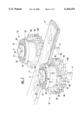
- FIG. 1 is an fragmentary environmental view of a pair of cutter head assemblies according to an embodiment of the present invention for forming a tongue and groove on respective edges of a flooring strip;
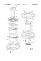
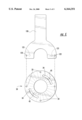
- FIG. 2 is an exploded view of a cutter head assembly 10 assembly as illustrated in FIG. 1;
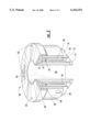
- FIG. 3 is a fragmentary vertical cut-away of a portion of the cutter head assembly 10 shown in FIGS. 1 and 2;
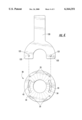
- FIG. 4 is a top plan view illustrating adjustment of the hub adjusting nut.
- FIG. 5 is a top plan view illustrating adjustment of the pressure sleeve adjusting nut.
- cutter head assemblies 10 and 10' for forming a tongue and groove on respective edges of a flooring strip "F" according to the present invention is illustrated in FIG. 1.
- Both cutter head assemblies 10 and 10' are identical insofar as the inventive concepts disclosed in this application are concerned. Therefore, it will be understood that in the following description reference to cutter head assembly 10 is applicable both to cutter head assembly 10 and cutter head assembly 10', shown in FIG. 1.
- Cutter head assemblies 10 and 10' are mounted on opposite sides of a path along which flooring strips "F" pass during manufacture, and simultaneously form a tongue on one side and a mating groove on the other side as the flooring strip "F" passes between them.
- the cutter head assemblies 10 and 10' are mounted for counter-rotation on respective motor spindles 11 which are rotated by heavy duty industrial motors (not shown).
- the motor which rotates cutter head assembly 10 and forms the groove is a 20 HP motor rotating at 3,600 rpm
- the motor which rotates cutter head assembly 10' and forms the tongue is a 30 HP motor rotating at 3,600 rpm.
- the invention contemplates the use of any type, speed or power of motor.
- cutter head assembly 10 is shown and illustrated in exploded form.
- An inner pressure sleeve 15 carries the other elements of the cutter head assembly 10 and is mounted onto motor shaft 11.
- Inner pressure sleeve 15 has an internal void which is pressurized with grease through a pressure port 16 positioned on a flange 17.
- a pressure release port 18 permits pressure within the inner pressure sleeve 15 to be released when the cutter head assembly 10 is being adjusted or removed from the motor shaft 11.
- the inner pressure sleeve 15 When pressurized, the inner pressure sleeve 15 expands towards the shaft 11, exerting pressure evenly onto all surfaces and in all directions, automatically centering the pressure sleeve 15 onto the motor shaft 11.
- the end of the inner pressure sleeve 15 opposite the flange 17 is provided with exterior threads 19 for receiving a threaded lock nut 20, thus capturing the remaining elements of the cutter head assembly 10.
- the inner pressure sleeve 15 is positioned concentrically through an hub adjusting nut 30, a pressure sleeve adjusting nut 40, an outer pressure sleeve 50, an outer hub 60 and an inner hub 70.
- Upper, middle and lower cutter plates 80, 90 and 100 respectively, each have central openings 81, 91 and 101 of different diameters for fitting onto shoulders having respective diameters, as described below.
- Each of the cutter plates 80, 90, 100 are also provided with bolt holes 82, 92, 102 which receive bolts 52, 62 and 73, and thus lock the cutter plates 80, 90 and 100 in proper orientation.
- Inner hub 70 resides innermost on the outer surface of the inner pressure sleeve 15. Pressurization of the inner pressure sleeve 15 clamps the inner hub 70 in a fixed orientation to the inner pressure sleeve 15 until the pressure is released.
- Inner hub 70 includes a bottom shoulder 71 which receives cutter plate 100.
- the radially-extending portion of the shoulder 71 includes bolt holes (not shown) which receive bolts 73 which also extend through the holes 102 in the cutter plate 100 and thus locks the cutter plate 100 to the inner hub 70.
- the outer pressure sleeve 50 resides adjacent the outer wall of the inner hub 70 and includes a bottom shoulder 51 which receives the cutter plate 90.
- the radially-extending portion of the bottom shoulder 51 includes bolt holes (not shown) which receive bolts 52 which also extend through the holes 92 in the cutter plate 90 and thus locks the cutter plate 90 to the outer pressure sleeve 50.
- the pressure sleeve 50 includes pressure port 56 and a pressure release port 57.
- the outer hub 60 resides concentric to and adjacent the outer wall of the outer pressure sleeve 50 and includes a bottom shoulder 61 which receives the cutter plate 80.
- the radially-extending portion of the bottom shoulder 61 includes bolt holes (not shown) which receive bolts 62 which also extend through the holes 82 in the cutter plate 80 and thus locks the cutter plate 80 to the outer hub 60.
- the outer hub 60 includes an access hole 62 aligned with the pressure port 56 in the outer pressure sleeve 50 for permitting access to the pressure port 56 and an access hole 63 aligned with the pressure release port 57 for permitting access to the pressure release port 57.
- the cutter plates 80, 90, 100 are thus stacked into a vertical array, each on a shoulder of a different, concentric element.
- the position of cutter plate 100 provides a reference point against which the cutter plates 80 and 90 are adjusted as needed. This is accomplished by rotation of the hub adjusting nut 30 and/or the pressure sleeve adjusting nut 40. Both nuts 30 and 40 are supported on respective upper shoulders 73, 74 of the inner hub 70 and are thus vertically immobilized with reference to inner hub 70.
- the hub adjusting nut 30 is provided with internal threads which mate with external threads 64 on the top end of the outer hub 60, such that rotation of the hub 30 raises or lowers the outer hub 60 and thus the cutter plate 80. Adjustment holes 33 in the top surface of the hub adjusting nut 30 permit rotation with a special wrench, as shown in FIG. 5. As described in further detail below, access slots 34 permit access through the hub adjusting nut 30 to the pressure sleeve adjusting nut 40.
- pressure sleeve adjusting nut 40 is provided with internal threads which mate with external threads 54 on the top end of the outer pressure sleeve 50, such that rotation of the pressure sleeve adjusting nut 40 raises or lowers the outer pressure sleeve 50 and thus the cutter plate 90.
- Adjustment holes 43 in the top surface of the pressure sleeve adjusting nut 40 permit rotation with a special wrench, as shown in FIG. 4.
- FIG. 3 The order of assembly of the cutter head assembly 10 is shown in FIG. 3, where the inner pressure sleeve 15 and the cutter plates 80, 90 and 100 have been omitted for clarity. Note the arrangement of the shoulders 51, 61, 71 which support, respectively the cutter plates 90, 80 and 100. As noted above, the hub and pressure sleeve adjusting nuts 30, 40 are supported on shoulders 73 and 74 of inner hub 70. Thus, rotation of the nut 30 or 40 will create vertical movement of the respective cutter plate 80 or 90.
- adjustment of the outer pressure sleeve 50 and thus the attached cutter plate 90 can be accomplished without removing the hub adjusting nut 30 or the hub 60 by use of a generally Y-shaped wrench 120 which includes two spaced-apart lugs 121 on one side spaced to fit through the slots 34 in the hub adjusting nut 30 and into two opposed adjustment holes 43 in the top surface of the pressure sleeve adjusting nut 40.
- a generally Y-shaped wrench 120 which includes two spaced-apart lugs 121 on one side spaced to fit through the slots 34 in the hub adjusting nut 30 and into two opposed adjustment holes 43 in the top surface of the pressure sleeve adjusting nut 40.
- there are 8 adjustment holes 43 in the pressure sleeve adjusting nut 40 each spaced 45 degrees apart.
- the slots 34 in the hub adjusting nut 30 are diametrically-opposed and each define an arc of 70 degrees.
- Adjustment of the of the outer hub 60 and thus the attached cutter plate 80 is accomplished by using the opposite side of the wrench 120, which has two spaced-apart lugs 122 which fit into any diametrically-opposed of the four equally-spaced adjustment holes 33, as shown in FIG. 5.
- Assembly of the cutter head assembly 10 is accomplished by bolting the bottom cutter plate 100 onto the shoulder 71 of the inner hub 70 using bolts 73.
- the inner hub 70 is placed into the outer pressure sleeve 50.
- the middle cutter plate 90 is then placed onto the shoulder 51 of the outer pressure sleeve 50 and bolted into place with the bolts 52.
- the assembly is inverted and placed onto the inner hub 70 and the attached bottom cutter blade 100.
- the upper cutter plate 80 is bolted to the shoulder 61 of the outer hub 60 with bolts 62.
- the outer hub 60 is then placed over the outer pressure sleeve 50. At this point all three cutter plates 80, 90 and 100 have been properly stacked, as shown in FIG. 1.
- the pressure sleeve adjusting nut 40 is placed onto the shoulder 74 of the inner hub 70 and threaded onto the threads 54 of the pressure sleeve 50.
- the outer hub 30 is then placed on the shoulder 73 of the inner hub 70 and threaded onto the threads 64 on the upper end of the outer hub 60.
- the inner pressure sleeve 15 is then inserted into the center of the inner hub 70, and the lock nut 20 is threaded onto the threads 19 on the bottom of the inner pressure sleeve 15 and tightened to the proper torque.
- the entire cutter head assembly 10 is then placed onto the motor spindle 11.
- the inner pressure sleeve 15 is then pressurized by introducing grease under pressure through the pressure port 16. Pressure is generally in the range 400-500 bar.
- the entire cutter head assembly 10 is locked onto the spindle 11.
- the outer pressure sleeve 50 is then pressurized by introducing grease into the pressure port 56. Pressure is generally in the range 400-500 bar. The pressure locks the top and middle cutter plates 80 and 90 together, to the outer pressure sleeve 50 and to the inner hub 70. According to this structure and assembly technique, the pressure exerted by the inner pressure sleeve 15 and the outer pressure sleeve 50 are isolated from each other and therefore do not interfere with the other. Concentricity of the cutter head assembly 10 on the spindle 11 established by pressurizing the inner pressure sleeve 15 is unaffected by subsequent pressurization of the outer pressure sleeve 50.
Landscapes
- Life Sciences & Earth Sciences (AREA)
- Engineering & Computer Science (AREA)
- Mechanical Engineering (AREA)
- Wood Science & Technology (AREA)
- Forests & Forestry (AREA)
- Physics & Mathematics (AREA)
- Fluid Mechanics (AREA)
- General Engineering & Computer Science (AREA)
- Processing Of Stones Or Stones Resemblance Materials (AREA)
- Earth Drilling (AREA)
Abstract
Description
Claims (16)
Priority Applications (5)
| Application Number | Priority Date | Filing Date | Title |
|---|---|---|---|
| US09/478,016 US6164351A (en) | 2000-01-05 | 2000-01-05 | Precision-balanced cutter head and method |
| US09/505,331 US6189196B1 (en) | 2000-01-05 | 2000-02-16 | Precision-balanced shaft and method |
| CA002328005A CA2328005A1 (en) | 2000-01-05 | 2000-12-12 | Precision-balanced cutter head and method |
| EP00311345A EP1114686A3 (en) | 2000-01-05 | 2000-12-19 | Rotatable cutter head assembly |
| MXPA00012861A MXPA00012861A (en) | 2000-01-05 | 2000-12-20 | Precision-balanced cutter head and method. |
Applications Claiming Priority (1)
| Application Number | Priority Date | Filing Date | Title |
|---|---|---|---|
| US09/478,016 US6164351A (en) | 2000-01-05 | 2000-01-05 | Precision-balanced cutter head and method |
Related Child Applications (1)
| Application Number | Title | Priority Date | Filing Date |
|---|---|---|---|
| US09/505,331 Continuation-In-Part US6189196B1 (en) | 2000-01-05 | 2000-02-16 | Precision-balanced shaft and method |
Publications (1)
| Publication Number | Publication Date |
|---|---|
| US6164351A true US6164351A (en) | 2000-12-26 |
Family
ID=23898205
Family Applications (2)
| Application Number | Title | Priority Date | Filing Date |
|---|---|---|---|
| US09/478,016 Expired - Lifetime US6164351A (en) | 2000-01-05 | 2000-01-05 | Precision-balanced cutter head and method |
| US09/505,331 Expired - Fee Related US6189196B1 (en) | 2000-01-05 | 2000-02-16 | Precision-balanced shaft and method |
Family Applications After (1)
| Application Number | Title | Priority Date | Filing Date |
|---|---|---|---|
| US09/505,331 Expired - Fee Related US6189196B1 (en) | 2000-01-05 | 2000-02-16 | Precision-balanced shaft and method |
Country Status (4)
| Country | Link |
|---|---|
| US (2) | US6164351A (en) |
| EP (1) | EP1114686A3 (en) |
| CA (1) | CA2328005A1 (en) |
| MX (1) | MXPA00012861A (en) |
Cited By (12)
| Publication number | Priority date | Publication date | Assignee | Title |
|---|---|---|---|---|
| US20050072491A1 (en) * | 2003-10-07 | 2005-04-07 | Baber Brad M. | Power tool support fixture |
| WO2006056456A1 (en) * | 2004-11-29 | 2006-06-01 | Hoesch Hohenlimburg Gmbh | High-speed milling cutter system and method for producing metallic guide elements |
| US20100164187A1 (en) * | 2007-03-06 | 2010-07-01 | The University Of Sheffield | Adaptive design of fixture for thin-walled shell/cylindrical components |
| US20110030303A1 (en) * | 2008-01-31 | 2011-02-10 | Valinge Innovation Belguim BVBA | Mechanical locking of floor panels, methods to install and uninstall panels, a method and an equipement to produce the locking system, a method to connect a displaceable tongue to a panel and a tongue blank |
| US20110303066A1 (en) * | 2010-06-09 | 2011-12-15 | Li Yuedui | Cutting apparatus with a pair of counter-rotating saw blades |
| US8505257B2 (en) | 2008-01-31 | 2013-08-13 | Valinge Innovation Ab | Mechanical locking of floor panels |
| US8713886B2 (en) | 2009-01-30 | 2014-05-06 | Valinge Innovation Ab | Mechanical lockings of floor panels and a tongue blank |
| US9121181B2 (en) * | 2011-07-29 | 2015-09-01 | Hamberger Industriewerke Gmbh | Connection for elastic or panel-type components, profiled slide, and floor covering |
| US9194134B2 (en) | 2013-03-08 | 2015-11-24 | Valinge Innovation Ab | Building panels provided with a mechanical locking system |
| US20160271709A9 (en) * | 2014-10-15 | 2016-09-22 | Kennametal Inc. | Tool for machining workpieces |
| US10640989B2 (en) | 2006-12-08 | 2020-05-05 | Valinge Innovation Ab | Mechanical locking of floor panels |
| US11020845B2 (en) * | 2019-07-13 | 2021-06-01 | Augustine Albert Iocco | Routing adapter for wide shallow recesses |
Families Citing this family (7)
| Publication number | Priority date | Publication date | Assignee | Title |
|---|---|---|---|---|
| US7219706B2 (en) * | 2002-09-06 | 2007-05-22 | Key Knife, Inc. | Apparatus having adjustable saws for wood cutting |
| DE20318942U1 (en) * | 2003-12-04 | 2005-04-14 | Urban Gmbh & Co Maschinenbau Kg | trimming device |
| EP1993792A2 (en) * | 2006-03-10 | 2008-11-26 | Mannington Mills, Inc. | A process and system for sub-dividing a laminated flooring substrate |
| WO2008076007A1 (en) * | 2006-12-19 | 2008-06-26 | Volvo Aero Corporation | A method of manufacturing a wall structure and a machining tool |
| DE102007001864A1 (en) * | 2007-01-12 | 2008-07-17 | Kennametal Inc. | milling |
| ITGE20070032A1 (en) * | 2007-03-14 | 2008-09-15 | Ts Tecnospamec S R L | CUTTING TOOL. |
| WO2010085886A1 (en) * | 2009-01-30 | 2010-08-05 | Rene St-Cyr (1996) Inc. | Manufacturing of tongue and groove profiles on hardwood floorboards |
Citations (8)
| Publication number | Priority date | Publication date | Assignee | Title |
|---|---|---|---|---|
| US1075907A (en) * | 1912-03-14 | 1913-10-14 | John C Dunton | Cutter-head for planers. |
| US1196191A (en) * | 1916-08-29 | Bushing | ||
| GB226727A (en) * | 1924-04-30 | 1925-01-01 | Robert Edward Maxim | Improvements in and relating to staircase housers, trenching tools, or the like for traversing operations in wood or other soft materials |
| US2751942A (en) * | 1952-04-10 | 1956-06-26 | Porter Cable Machine Co | Cutter arbor shaft for portable power operated tools |
| US5303754A (en) * | 1991-11-18 | 1994-04-19 | Kauko Rautio | Fastening system for a rip-saw blade and a chipping edger |
| US5462293A (en) * | 1993-03-22 | 1995-10-31 | Etp Transmission Ab | Chuck having an integrated cone or machine spindle |
| US5672026A (en) * | 1993-06-17 | 1997-09-30 | Etp Transmission Ab | Hydraulic friction clamp coupling for shafts |
| US5855446A (en) * | 1995-02-01 | 1999-01-05 | Etp Transmission Ab | Hydraulic clamp bushing having sigma shaped bushing ends |
Family Cites Families (1)
| Publication number | Priority date | Publication date | Assignee | Title |
|---|---|---|---|---|
| US5996659A (en) * | 1998-01-09 | 1999-12-07 | Burgess; Michael | Matched pair of plywood edge-banding router bits |
-
2000
- 2000-01-05 US US09/478,016 patent/US6164351A/en not_active Expired - Lifetime
- 2000-02-16 US US09/505,331 patent/US6189196B1/en not_active Expired - Fee Related
- 2000-12-12 CA CA002328005A patent/CA2328005A1/en not_active Abandoned
- 2000-12-19 EP EP00311345A patent/EP1114686A3/en not_active Withdrawn
- 2000-12-20 MX MXPA00012861A patent/MXPA00012861A/en unknown
Patent Citations (8)
| Publication number | Priority date | Publication date | Assignee | Title |
|---|---|---|---|---|
| US1196191A (en) * | 1916-08-29 | Bushing | ||
| US1075907A (en) * | 1912-03-14 | 1913-10-14 | John C Dunton | Cutter-head for planers. |
| GB226727A (en) * | 1924-04-30 | 1925-01-01 | Robert Edward Maxim | Improvements in and relating to staircase housers, trenching tools, or the like for traversing operations in wood or other soft materials |
| US2751942A (en) * | 1952-04-10 | 1956-06-26 | Porter Cable Machine Co | Cutter arbor shaft for portable power operated tools |
| US5303754A (en) * | 1991-11-18 | 1994-04-19 | Kauko Rautio | Fastening system for a rip-saw blade and a chipping edger |
| US5462293A (en) * | 1993-03-22 | 1995-10-31 | Etp Transmission Ab | Chuck having an integrated cone or machine spindle |
| US5672026A (en) * | 1993-06-17 | 1997-09-30 | Etp Transmission Ab | Hydraulic friction clamp coupling for shafts |
| US5855446A (en) * | 1995-02-01 | 1999-01-05 | Etp Transmission Ab | Hydraulic clamp bushing having sigma shaped bushing ends |
Cited By (30)
| Publication number | Priority date | Publication date | Assignee | Title |
|---|---|---|---|---|
| US20050072491A1 (en) * | 2003-10-07 | 2005-04-07 | Baber Brad M. | Power tool support fixture |
| WO2006056456A1 (en) * | 2004-11-29 | 2006-06-01 | Hoesch Hohenlimburg Gmbh | High-speed milling cutter system and method for producing metallic guide elements |
| US20080145165A1 (en) * | 2004-11-29 | 2008-06-19 | Hoesch Schwerter Profile Gmbh | High-Speed Milling Cutter System and Method for Producing Metallic Guide Elements |
| US7707705B2 (en) | 2004-11-29 | 2010-05-04 | Hoesch Schwerter Profile Gmbh | High-speed milling cutter system and method for producing metallic guide elements |
| US10640989B2 (en) | 2006-12-08 | 2020-05-05 | Valinge Innovation Ab | Mechanical locking of floor panels |
| US20140283368A1 (en) * | 2007-03-06 | 2014-09-25 | The University Of Sheffield | Adaptive design of fixture for thin-walled shell/cylindrical components |
| US20100164187A1 (en) * | 2007-03-06 | 2010-07-01 | The University Of Sheffield | Adaptive design of fixture for thin-walled shell/cylindrical components |
| US9340974B2 (en) | 2008-01-31 | 2016-05-17 | Valinge Innovation Ab | Mechanical locking of floor panels |
| US10006210B2 (en) | 2008-01-31 | 2018-06-26 | Valinge Innovation Ab | Mechanical locking of floor panels |
| US12024898B2 (en) * | 2008-01-31 | 2024-07-02 | Välinge Innovation AB | Mechanical locking of floor panels |
| US8505257B2 (en) | 2008-01-31 | 2013-08-13 | Valinge Innovation Ab | Mechanical locking of floor panels |
| US20220143718A1 (en) * | 2008-01-31 | 2022-05-12 | Välinge Innovation AB | Mechanical locking of floor panels |
| US11078673B2 (en) | 2008-01-31 | 2021-08-03 | Valinge Innovation Ab | Mechanical locking of floor panels |
| US8627862B2 (en) * | 2008-01-31 | 2014-01-14 | Valinge Innovation Ab | Mechanical locking of floor panels, methods to install and uninstall panels, a method and an equipment to produce the locking system, a method to connect a displaceable tongue to a panel and a tongue blank |
| US20110030303A1 (en) * | 2008-01-31 | 2011-02-10 | Valinge Innovation Belguim BVBA | Mechanical locking of floor panels, methods to install and uninstall panels, a method and an equipement to produce the locking system, a method to connect a displaceable tongue to a panel and a tongue blank |
| US10526792B2 (en) | 2008-01-31 | 2020-01-07 | Valinge Innovation Ab | Mechanical locking of floor panels |
| US9309679B2 (en) | 2009-01-30 | 2016-04-12 | Valinge Innovation Ab | Mechanical lockings of floor panels and a tongue blank |
| US8713886B2 (en) | 2009-01-30 | 2014-05-06 | Valinge Innovation Ab | Mechanical lockings of floor panels and a tongue blank |
| US10214915B2 (en) * | 2009-01-30 | 2019-02-26 | Valinge Innovation Ab | Mechanical lockings of floor panels and a tongue blank |
| US20190376298A1 (en) * | 2009-01-30 | 2019-12-12 | Valinge Innovation Ab | Mechanical lockings of floor panels and a tongue blank |
| US9540826B2 (en) | 2009-01-30 | 2017-01-10 | Valinge Innovation Ab | Mechanical lockings of floor panels and a tongue blank |
| US10934721B2 (en) * | 2009-01-30 | 2021-03-02 | Valinge Innovation Ab | Mechanical lockings of floor panels and a tongue blank |
| US20110303066A1 (en) * | 2010-06-09 | 2011-12-15 | Li Yuedui | Cutting apparatus with a pair of counter-rotating saw blades |
| US9121181B2 (en) * | 2011-07-29 | 2015-09-01 | Hamberger Industriewerke Gmbh | Connection for elastic or panel-type components, profiled slide, and floor covering |
| US9194134B2 (en) | 2013-03-08 | 2015-11-24 | Valinge Innovation Ab | Building panels provided with a mechanical locking system |
| US9945130B2 (en) | 2013-03-08 | 2018-04-17 | Valinge Innovation Ab | Building panels provided with a mechanical locking system |
| US9482012B2 (en) | 2013-03-08 | 2016-11-01 | Valinge Innovation Ab | Building panels provided with a mechanical locking system |
| US20160271709A9 (en) * | 2014-10-15 | 2016-09-22 | Kennametal Inc. | Tool for machining workpieces |
| US10155272B2 (en) * | 2014-10-15 | 2018-12-18 | Kennametal Inc. | Tool for machining workpieces |
| US11020845B2 (en) * | 2019-07-13 | 2021-06-01 | Augustine Albert Iocco | Routing adapter for wide shallow recesses |
Also Published As
| Publication number | Publication date |
|---|---|
| CA2328005A1 (en) | 2001-07-05 |
| EP1114686A3 (en) | 2002-10-02 |
| US6189196B1 (en) | 2001-02-20 |
| MXPA00012861A (en) | 2003-04-25 |
| EP1114686A2 (en) | 2001-07-11 |
Similar Documents
| Publication | Publication Date | Title |
|---|---|---|
| US6164351A (en) | Precision-balanced cutter head and method | |
| EP1715735B1 (en) | Tree stump grinder | |
| US5027684A (en) | Collar for mounting a split saw blade on an arbor | |
| US4074946A (en) | Shaft-rotor coupling | |
| US4267759A (en) | Tool safety lock ring | |
| US7891388B2 (en) | Knife and knife assembly for a planer side head | |
| DE69526451T2 (en) | ROTATING RING-SHAPED FORGING TOOL WITH FRONT LOAD | |
| CN109693129B (en) | Planet carrier machining device and planet carrier machining method | |
| US4531926A (en) | Adjustable pitch sprocket | |
| EP0008631B1 (en) | Gang cutter | |
| JP2001515418A (en) | Equipment for cutting wood and other materials to any desired width | |
| JP2000304122A (en) | Drive axle assembly and positioning method for positioning ring gear relative to differential case in the assembly | |
| EP0098298B1 (en) | High speed milling cutter | |
| EP1615752B1 (en) | Cutter head for a meat cutter | |
| US4547997A (en) | Adjustable tool mount | |
| US4447993A (en) | Alignment means for centrifugal blasting wheel | |
| US5522441A (en) | Wood lathe tooling | |
| US20130047812A1 (en) | Locking Taper Saw Blade Mounting Assembly and Method | |
| EP1530694B1 (en) | Divided driver device for a slip ring seal | |
| WO2009121461A1 (en) | Tool for turn-turn broaching or external milling | |
| DE69126216T2 (en) | Rotating ring-shaped cutting tool | |
| CN218904903U (en) | Grinding wheel distance adjusting device and cutting and grinding equipment | |
| US4036313A (en) | Mounting for inboard cutters on a raise drill | |
| CN219444395U (en) | Quick-change processing device for valve body of brake system part | |
| CN212145639U (en) | Adjusting mechanism of machine tool |
Legal Events
| Date | Code | Title | Description |
|---|---|---|---|
| AS | Assignment |
Owner name: TRIANGLE PACIFIC CORPORATION, TEXAS Free format text: ASSIGNMENT OF ASSIGNORS INTEREST;ASSIGNOR:WEATHERS, DAVID L.;REEL/FRAME:010521/0383 Effective date: 20000104 |
|
| AS | Assignment |
Owner name: TRIANGLE PACIFIC CORP., TEXAS Free format text: CORRECTION OF RECORDATION OF ASSIGNMENT REEL & FRAME NO. OF THE INCORRECTLY RECORDED ASSIGNMENT 010521/0383; CORRECT "TRIANGLE PACIFIC CORPORATION" TO "TRIANGLE PACIFIC CORP." ENCLOSED ARE THE RECORDED ASSIGNMENT AND RECORDATION COVER SHEET.;ASSIGNOR:TRIANGLE PACIFIC CORPORATION;REEL/FRAME:010777/0752 Effective date: 20000104 |
|
| STCF | Information on status: patent grant |
Free format text: PATENTED CASE |
|
| FPAY | Fee payment |
Year of fee payment: 4 |
|
| FPAY | Fee payment |
Year of fee payment: 8 |
|
| FPAY | Fee payment |
Year of fee payment: 12 |
|
| AS | Assignment |
Owner name: AFI LICENSING LLC, PENNSYLVANIA Free format text: ASSIGNMENT OF ASSIGNORS INTEREST;ASSIGNOR:ARMSTRONG FLOORING INC;REEL/FRAME:040028/0243 Effective date: 20160824 |
|
| AS | Assignment |
Owner name: ARMSTRONG HARDWOOD FLOORING COMPANY, PENNSYLVANIA Free format text: ASSIGNMENT OF ASSIGNORS INTEREST;ASSIGNOR:ARMSTRONG FLOORING, INC.;REEL/FRAME:048171/0134 Effective date: 20181231 |
|
| AS | Assignment |
Owner name: ALLY BANK, AS COLLATERAL AGENT, NEW YORK Free format text: SECURITY AGREEMENT;ASSIGNORS:HOMERWOOD HARDWOOD FLOORING COMPANY, LLC;AHF, LLC;REEL/FRAME:048544/0630 Effective date: 20181231 |
|
| AS | Assignment |
Owner name: AHF, LLC (F/K/A ARMSTRONG HARDWOOD FLOORING COMPANY), PENNSYLVANIA Free format text: RELEASE BY SECURED PARTY;ASSIGNOR:ALLY BANK, AS COLLATERAL AGENT;REEL/FRAME:058850/0408 Effective date: 20220201 Owner name: HOMERWOOD HARDWOOD FLOORING COMPANY, LLC, PENNSYLVANIA Free format text: RELEASE BY SECURED PARTY;ASSIGNOR:ALLY BANK, AS COLLATERAL AGENT;REEL/FRAME:058850/0408 Effective date: 20220201 |