KR20200077624A - Reel based lacing system - Google Patents
Reel based lacing system Download PDFInfo
- Publication number
- KR20200077624A KR20200077624A KR1020207018257A KR20207018257A KR20200077624A KR 20200077624 A KR20200077624 A KR 20200077624A KR 1020207018257 A KR1020207018257 A KR 1020207018257A KR 20207018257 A KR20207018257 A KR 20207018257A KR 20200077624 A KR20200077624 A KR 20200077624A
- Authority
- KR
- South Korea
- Prior art keywords
- handle
- pole
- spool
- teeth
- string
- Prior art date
Links
Images


Classifications
-
- A—HUMAN NECESSITIES
- A43—FOOTWEAR
- A43C—FASTENINGS OR ATTACHMENTS OF FOOTWEAR; LACES IN GENERAL
- A43C11/00—Other fastenings specially adapted for shoes
- A43C11/16—Fastenings secured by wire, bolts, or the like
- A43C11/165—Fastenings secured by wire, bolts, or the like characterised by a spool, reel or pulley for winding up cables, laces or straps by rotation
-
- A—HUMAN NECESSITIES
- A43—FOOTWEAR
- A43B—CHARACTERISTIC FEATURES OF FOOTWEAR; PARTS OF FOOTWEAR
- A43B23/00—Uppers; Boot legs; Stiffeners; Other single parts of footwear
- A43B23/02—Uppers; Boot legs
-
- A—HUMAN NECESSITIES
- A43—FOOTWEAR
- A43B—CHARACTERISTIC FEATURES OF FOOTWEAR; PARTS OF FOOTWEAR
- A43B5/00—Footwear for sporting purposes
- A43B5/16—Skating boots
-
- A—HUMAN NECESSITIES
- A43—FOOTWEAR
- A43C—FASTENINGS OR ATTACHMENTS OF FOOTWEAR; LACES IN GENERAL
- A43C11/00—Other fastenings specially adapted for shoes
- A43C11/008—Combined fastenings, e.g. to accelerate undoing or fastening
-
- A—HUMAN NECESSITIES
- A43—FOOTWEAR
- A43C—FASTENINGS OR ATTACHMENTS OF FOOTWEAR; LACES IN GENERAL
- A43C11/00—Other fastenings specially adapted for shoes
- A43C11/20—Fastenings with tightening devices mounted on the tongue
-
- A—HUMAN NECESSITIES
- A43—FOOTWEAR
- A43C—FASTENINGS OR ATTACHMENTS OF FOOTWEAR; LACES IN GENERAL
- A43C11/00—Other fastenings specially adapted for shoes
- A43C11/24—Ornamental buckles or other ornaments for shoes, with fastening function
-
- A—HUMAN NECESSITIES
- A43—FOOTWEAR
- A43C—FASTENINGS OR ATTACHMENTS OF FOOTWEAR; LACES IN GENERAL
- A43C7/00—Holding-devices for laces
- A43C7/08—Clamps drawn tight by laces
-
- B—PERFORMING OPERATIONS; TRANSPORTING
- B65—CONVEYING; PACKING; STORING; HANDLING THIN OR FILAMENTARY MATERIAL
- B65H—HANDLING THIN OR FILAMENTARY MATERIAL, e.g. SHEETS, WEBS, CABLES
- B65H75/00—Storing webs, tapes, or filamentary material, e.g. on reels
- B65H75/02—Cores, formers, supports, or holders for coiled, wound, or folded material, e.g. reels, spindles, bobbins, cop tubes, cans, mandrels or chucks
- B65H75/34—Cores, formers, supports, or holders for coiled, wound, or folded material, e.g. reels, spindles, bobbins, cop tubes, cans, mandrels or chucks specially adapted or mounted for storing and repeatedly paying-out and re-storing lengths of material provided for particular purposes, e.g. anchored hoses, power cables
- B65H75/38—Cores, formers, supports, or holders for coiled, wound, or folded material, e.g. reels, spindles, bobbins, cop tubes, cans, mandrels or chucks specially adapted or mounted for storing and repeatedly paying-out and re-storing lengths of material provided for particular purposes, e.g. anchored hoses, power cables involving the use of a core or former internal to, and supporting, a stored package of material
- B65H75/44—Constructional details
- B65H75/4418—Arrangements for stopping winding or unwinding; Arrangements for releasing the stop means
- B65H75/4428—Arrangements for stopping winding or unwinding; Arrangements for releasing the stop means acting on the reel or on a reel blocking mechanism
- B65H75/4431—Manual stop or release button
-
- B—PERFORMING OPERATIONS; TRANSPORTING
- B65—CONVEYING; PACKING; STORING; HANDLING THIN OR FILAMENTARY MATERIAL
- B65H—HANDLING THIN OR FILAMENTARY MATERIAL, e.g. SHEETS, WEBS, CABLES
- B65H2701/00—Handled material; Storage means
- B65H2701/30—Handled filamentary material
- B65H2701/39—Other types of filamentary materials or special applications
-
- Y—GENERAL TAGGING OF NEW TECHNOLOGICAL DEVELOPMENTS; GENERAL TAGGING OF CROSS-SECTIONAL TECHNOLOGIES SPANNING OVER SEVERAL SECTIONS OF THE IPC; TECHNICAL SUBJECTS COVERED BY FORMER USPC CROSS-REFERENCE ART COLLECTIONS [XRACs] AND DIGESTS
- Y10—TECHNICAL SUBJECTS COVERED BY FORMER USPC
- Y10T—TECHNICAL SUBJECTS COVERED BY FORMER US CLASSIFICATION
- Y10T24/00—Buckles, buttons, clasps, etc.
- Y10T24/21—Strap tighteners
- Y10T24/2183—Ski, boot, and shoe fasteners
-
- Y—GENERAL TAGGING OF NEW TECHNOLOGICAL DEVELOPMENTS; GENERAL TAGGING OF CROSS-SECTIONAL TECHNOLOGIES SPANNING OVER SEVERAL SECTIONS OF THE IPC; TECHNICAL SUBJECTS COVERED BY FORMER USPC CROSS-REFERENCE ART COLLECTIONS [XRACs] AND DIGESTS
- Y10—TECHNICAL SUBJECTS COVERED BY FORMER USPC
- Y10T—TECHNICAL SUBJECTS COVERED BY FORMER US CLASSIFICATION
- Y10T29/00—Metal working
- Y10T29/49—Method of mechanical manufacture
- Y10T29/49826—Assembling or joining
- Y10T29/4984—Retaining clearance for motion between assembled parts
-
- Y—GENERAL TAGGING OF NEW TECHNOLOGICAL DEVELOPMENTS; GENERAL TAGGING OF CROSS-SECTIONAL TECHNOLOGIES SPANNING OVER SEVERAL SECTIONS OF THE IPC; TECHNICAL SUBJECTS COVERED BY FORMER USPC CROSS-REFERENCE ART COLLECTIONS [XRACs] AND DIGESTS
- Y10—TECHNICAL SUBJECTS COVERED BY FORMER USPC
- Y10T—TECHNICAL SUBJECTS COVERED BY FORMER US CLASSIFICATION
- Y10T74/00—Machine element or mechanism
- Y10T74/21—Elements
- Y10T74/2133—Pawls and ratchets
Abstract
릴 기반 끈 조임 시스템이 개시된다. 릴은 손잡이를 조이는 방향으로 회전시킴에 의해서 스풀 주위에 끈을 증분적으로 조이는 것이 허용되도록 구성될 수 있다. 몇몇 실시예에 있어서, 상기 시스템은 손잡이가 풀리는 방향으로 회전하는 것에 저항하도록 구성된 실질적으로 유연한 폴 빔과 하우징에 대하여 폴을 편향시키고 손잡이가 조이는 방향으로 회전될 때 폴이 하우징으로부터 옮겨지는 것이 허용되도록 구성된 폴 스프링을 포함할 수 있다.Disclosed is a reel based string tightening system. The reel can be configured to allow incremental tightening of the string around the spool by rotating the handle in the direction of tightening. In some embodiments, the system deflects the poles relative to the housing and the substantially flexible pole beam configured to resist rotation of the handle in a loosening direction and allows the pole to be displaced from the housing when the handle is rotated in the tightening direction. It may include a configured pole spring.
Description
관련 출원에 대한 교차 참조Cross reference to related applications
본 출원은 제목이 릴 기반 끈 조임 시스템인 미국 가특허 출원 번호 제61/330,129호에 대한 우선권을 주장하고, 그 출원의 전체가 여기에 참조로 합체된다.This application claims priority to U.S. Provisional Patent Application No. 61/330,129, titled reel-based string fastening system, the entirety of which is incorporated herein by reference.
여기에 개시된 실시예는 발 착용구, 잠금 가능한 가방들, 보호 장구 등을 포함하는 임의의 다양한 물품들에 있어서 결합 되어 사용되거나 단독으로 사용되는 끈 조임 또는 잠금 시스템과 그들의 관련 구성부품들에 관한 것이다.Embodiments disclosed herein relate to string tightening or locking systems used in combination or alone in any of a variety of articles including foot wear, lockable bags, protective gear, and the like, and their associated components. .
발 착용구와 같은 물품들을 조이기 위한 많은 방법과 기구들이 존재한다. 그럼에도 불구하고, 개선된 방법들과 장치들에 대한 요구가 있다.There are many methods and mechanisms for tightening items such as foot wear. Nevertheless, there is a need for improved methods and devices.
몇몇 실시예에 있어서, 끈 조임 시스템에 사용되기 위한 릴이 개시된다. 릴은 복수의 하우징 치들을 구비한 하우징을 포함할 수 있다. 릴은 하우징에 의해서 지지되는 스풀을 포함할 수 있고, 스풀은 하우징에 대하여 회전 가능할 수 있다. 스풀은 채널을 포함할 수 있고, 채널은 스풀이 조이는 방향으로 회전될 때 끈 조임 시스템을 조이기 위하여 안으로 끈을 수집하도록 구성될 수 있다. 채널은 스풀이 풀리는 방향으로 회전될 때 끈 조임 시스템을 풀기 위하여 끈을 방출할 수 있다. 릴은 하우징에 의해서 지지되는 손잡이를 포함하고, 손잡이는 하우징에 대하여 회전 가능할 수 있다. 손잡이의 회전으로 또한 스풀이 회전되게 하도록 손잡이는 스풀에 결합 될 수 있다. 손잡이는 하나 또는 그 이상의 폴들을 포함할 수 있고, 상기 하나 또는 그 이상의 폴들의 적어도 하나는 폴 빔과 폴 스프링을 포함할 수 있다. 폴 빔은 제1위치와 제2위치 사이에서 이동이 가능할 수 있고, 폴 스프링은 폴 빔을 제1위치를 향하여 편향시키도록 구성될 수 있다. 폴 빔은, 푸는 힘이 손잡이에 작용 될 때 푸는 힘의 실질적인 부분을 폴 스프링에 전달하지 않고 손잡이가 푸는 방향으로 회전하는 것을 방지하도록 폴 빔이 제1위치에 있을 때 하우징 치들과 맞물리도록 구성된, 하나 또는 그 이상의 폴 치들을 포함할 수 있다. 몇몇 실시 예에 있어서, 폴 빔 및 폴 스프링은 일체로 형성될 수 있다(예를 들면, 일체로 성형 됨). 몇몇 실시 예에 있어서, 상기 하나 또는 그 이상의 폴 치들은, 상기 손잡이 및 스풀이 조이는 방향으로 회전하는 것을 허용하도록 손잡이가 조이는 방향으로 회전될 때 하우징 치들로부터 제2위치로 옮겨질 수 있다.In some embodiments, a reel for use in a string tightening system is disclosed. The reel can include a housing having a plurality of housing teeth. The reel can include a spool supported by the housing, and the spool can be rotatable relative to the housing. The spool can include a channel, and the channel can be configured to collect the string in to tighten the string tightening system when the spool is rotated in the tightening direction. The channel can release the string to loosen the string tightening system when the spool is rotated in the unwinding direction. The reel includes a handle supported by the housing, and the handle can be rotatable relative to the housing. The handle can also be coupled to the spool so that the rotation of the handle also causes the spool to rotate. The handle can include one or more poles, and at least one of the one or more poles can include a pole beam and a pole spring. The pole beam may be movable between the first position and the second position, and the pole spring may be configured to deflect the pole beam toward the first position. The pole beam is configured to engage the housing teeth when the pole beam is in the first position to prevent the handle from rotating in the loosening direction without transmitting a substantial portion of the loosening force to the pole spring when the release force is applied to the handle, It can include one or more poles. In some embodiments, the pole beam and pole spring may be integrally formed (eg, integrally molded). In some embodiments, the one or more pole teeth may be moved from the housing teeth to the second position when the handle is rotated in the tightening direction to allow the handle and spool to rotate in the tightening direction.
몇몇 실시 예에 있어서, 하우징 치들은 반경 방향으로 연장될 수 있고, 상기 폴 빔은 제1위치와 제2위치 사이에서 반경 방향으로 이동이 가능할 수 있고, 손잡이는 구속된 위치와 구속이 해제된 위치 사이에서 축선 방향으로 이동이 가능할 수 있다. 손잡이가 구속이 해제된 위치에 있을 때, 스풀은 풀리는 방향으로 회전하는 것이 허용될 수 있다. 하나 또는 그 이상의 폴들은, 손잡이에 푸는 힘이 작용 되었을 때, 손잡이에 축선 방향으로 실질적인 힘을 작용하지 않고 풀리는 방향으로 손잡이가 회전하는 것이 방지되도록 하우징 치들과 맞물리도록 구성될 수 있다. In some embodiments, the housing teeth may extend radially, the pole beam may be movable radially between the first position and the second position, and the handle is a restrained position and a restrained position It may be possible to move in the axial direction between. When the handle is in the released position, the spool can be allowed to rotate in the unwinding direction. The one or more poles may be configured to engage the housing teeth to prevent rotation of the handle in a disengaging direction without applying a substantial force in the axial direction to the handle when a release force is applied to the handle.
몇몇 실시 예에서, 폴이 개시되고, 폴은 손잡이가 풀리는 방향으로 회전하는 것을 방지하도록 푸는 힘이 다중의 치들에 분배되도록 적어도 두 개의 대응하는 하우징 치들과 동시에 맞물리도록 구성된 적어도 두 개의 폴을 포함할 수 있다. 몇몇 실시 예에 있어서, 폴 빔은 손잡이에 푸는 힘이 작용 되었을 때 하우징 치들을 향하여 가압 되도록 구성될 수 있다. 사용자가 푸는 방향으로 손잡이를 돌리거나 스풀에 연결된 끈의 장력에 의해서 푸는 힘이 손잡이에 작용 될 수 있다. 폴 빔은 피봇 축에 대하여 반경 방향으로 회전하도록 구성될 수 있고, 하나 또는 그 이상의 폴 치들은 상기 피봇 축으로부터 연장되는 접선으로부터 반경 방향 외측 위치에서 상기 하우징 치들과 맞물릴 수 있다. 폴 치들은, 푸는 힘이 작용 되었을 때 폴 빔이 하우징 치들을 향하여 가압 되도록, 푸는 힘이 손잡이에 작용 되었을 때 폴 빔이 하우징 치들의 일면을 가압하도록 구성된 일면을 구비할 수 있다. 적어도 하나의 폴 치의 일면이 하우징 치의 면으로부터 맞물림이 해제되도록 손잡이가 조이는 방향으로 회전되지 않으면 폴 빔은 제2위치로 이동하지 않도록 될 수 있다. 폴 빔의 일 측은, 푸는 힘이 손잡이에 작용 되었을 때 하나 또는 그 이상의 치들과 맞물리지 않는 하나 또는 그 이상의 하우징 치들과 접촉하도록 구성될 수 있고 폴 빔은 부가된 지지를 제공하기 위하여 하우징 치들을 향하여 가압 될 수 있다. In some embodiments, the pawl is initiated, and the pawl comprises at least two pawls configured to engage simultaneously with at least two corresponding housing teeth so that the unwinding force is distributed to multiple teeth to prevent the handle from rotating in the unlocking direction. Can. In some embodiments, the pole beam can be configured to be pushed toward the housing teeth when a loosening force is applied to the handle. The loosening force can be applied to the handle by rotating the handle in the direction the user loosens or by the tension of the string connected to the spool. The pole beam can be configured to rotate radially about the pivot axis, and one or more pole teeth can engage the housing teeth in a radially outer position from a tangent extending from the pivot axis. The pole teeth may have one surface configured to press the pole beam against the housing teeth when the loosening force is applied, so that the pole beam presses one surface of the housing teeth when the loosening force is applied to the handle. The pole beam may be prevented from moving to the second position if one side of the at least one pole tooth is not rotated in the direction in which the handle is tightened to disengage from the face of the housing tooth. One side of the pole beam can be configured to contact one or more housing teeth that do not engage with one or more teeth when a release force is applied to the handle and the pole beam is pressed against the housing teeth to provide added support. Can be.
몇몇 실시 예에 있어서, 끈 조임 시스템에 사용되기 위한 릴을 제조하는 방법이 개시된다. 상기 방법은 하우징을 제공하는 단계를 포함하고, 하우징은 복수의 하우징 치들을 포함할 수 있다. 상기 방법은 상기 하우징 내에 스풀을 배치하는 단계를 포함하고, 스풀은 상기 하우징에 대하여 회전 가능하다. 스풀은 형성된 채널을 포함하고, 채널은 스풀이 조이는 방향으로 회전할 때 끈 조임 시스템을 조이도록 끈을 수집하도록 구성될 수 있다. 채널을 스풀이 풀리는 방향으로 회전될 때 끈 조임 시스템을 풀기 위하여 끈을 방출하도록 구성될 수 있다. 상기 방법은 하우징에 손잡이를 부착하는 단계를 포함할 수 있고, 손잡이는 하우징에 대하여 회전가능하다. 손잡이의 회전이 스풀을 또한 회전시키도록 손잡이는 스풀에 결합 될 수 있다. 손잡이는 하나 또는 그 이상의 폴들을 포함하고, 하나 또는 그 이상의 폴들의 적어도 하나는 폴 빔과 폴 스프링을 포함할 수 있다. 폴 빔은 제1위치와 제2위치 사이에서 이동 가능하고 폴 스프링은 제1위치를 향하여 폴 빔을 편향시키도록 구성될 수 있다. 폴 빔은 풀리는 방향으로 푸는 힘이 상기 손잡이를 회전시키도록 작용 될 때 푸는 힘의 실질적인 부분을 폴 스프링에 전달하지 않고 손잡이가 풀리는 방향으로 회전하는 것을 방지하도록 폴 빔이 제1위치에 있을 때 하우징 치들과 맞물리도록 구성된 하나 또는 그 이상의 폴 치들을 포함할 수 있다. 하나 또는 그 이상의 폴 치들은 손잡이 및 스풀이 조이는 방향으로 회전하는 것을 허용하도록 손잡이가 조이는 방향으로 회전될 때 하우징 치들로부터 떨어져서 제2위치로 옮겨질 수 있다. 몇몇 실시 예에서, 폴 빔과 폴 스프링은 일체로 형성될 수 있다.In some embodiments, a method of making a reel for use in a string tightening system is disclosed. The method includes providing a housing, and the housing can include a plurality of housing teeth. The method includes placing a spool in the housing, the spool being rotatable relative to the housing. The spool includes a formed channel, and the channel can be configured to collect the string to tighten the string tightening system when the spool rotates in the tightening direction. It can be configured to release the string to loosen the string tightening system when the channel is rotated in the direction the spool is released. The method can include attaching a handle to the housing, the handle being rotatable relative to the housing. The handle can be coupled to the spool so that rotation of the handle also rotates the spool. The handle may include one or more poles, and at least one of the one or more poles may include a pole beam and a pole spring. The pole beam is movable between the first position and the second position and the pole spring can be configured to deflect the pole beam towards the first position. The pole beam is a housing when the pole beam is in the first position to prevent the handle from rotating in the direction of release without transmitting a substantial portion of the release force to the pole spring when the release force in the direction of release acts to rotate the handle. It may include one or more pole teeth configured to engage teeth. The one or more pole teeth can be moved away from the housing teeth to the second position when the handle is rotated in the tightening direction to allow the handle and spool to rotate in the tightening direction. In some embodiments, the pole beam and pole spring may be integrally formed.
몇몇 실시 예에 있어서, 끈 조임 시스템에서 릴과 사용되기 위한 폴이 개시된다. 폴은 릴의 하우징의 하우징 치들과 접촉하도록 구성된 하나 또는 그 이상의 폴 치들을 구비하는 폴 빔을 포함할 수 있다. 폴 빔은 제1위치와 제2위치 사이에서 이동이 가능할 수 있다. 폴은 폴 빔을 제1위치로 편향시키도록 구성된 폴 스프링을 포함할 수 있다. 상기 하나 또는 그 이상의 폴 치들은 푸는 힘이 폴에 작용 될 때 푸는 힘의 실질적인 부분을 폴 스프링에 전달시키지 않고 상기 폴이 푸는 방향으로 이동하는 것을 방지하도록 폴 빔이 제1위치에 있을 때 하우징 치들과 맞물릴 수 있다. 하나 또는 그 이상의 폴 치들은 폴들이 조이는 방향으로 이동하는 것을 허용하도록 폴 빔이 제2위치에 있을 때 하우징 치들과 맞물림이 해제될 수 있다. 몇몇 실시예에 있어서, 폴 빔과 폴 스프링은 일체로 형성될 수 있다.In some embodiments, a pole for use with a reel in a string tightening system is disclosed. The pole can include a pole beam having one or more pole teeth configured to contact the housing teeth of the housing of the reel. The pole beam may be movable between the first position and the second position. The pole can include a pole spring configured to deflect the pole beam to a first position. The one or more pole teeth are housing teeth when the pole beam is in the first position to prevent the pole from moving in the release direction without transferring a substantial portion of the release force to the pole spring when the release force acts on the pole. Can interlock with. One or more pole teeth can be disengaged from the housing teeth when the pole beam is in the second position to allow the poles to move in the tightening direction. In some embodiments, the pole beam and pole spring may be integrally formed.
몇몇 실시예에 있어서, 끈 조임 시스템에서 사용되기 위한 릴이 개시된다. 릴은 복수의 하우징 치들을 포함하는 하우징과 하우징에 의해서 지지되는 스풀을 포함하고, 스풀은 하우징에 대하여 회전가능하다. 스풀은 채널을 포함할 수 있고, 채널은 스풀이 조이는 방향으로 회전될 때 끈 조임 시스템을 조이도록 끈을 모으고 스풀이 풀리는 방향으로 회전될 때 끈 조임 시스템을 풀도록 끈을 방출하도록 구성될 수 있다. 릴은 하우징에 의해서 지지되는 손잡이를 포함할 수 있고, 손잡이는 하우징에 대하여 회전 가능하다. 손잡이의 회전이 또한 스풀을 회전하게 하도록 손잡이는 스풀에 결합될 수 있다. 손잡이는 하우징 치들과 접촉하도록 구성된 하나 또는 그 이상의 폴들을 포함할 수 있고, 하나 또는 그 이상의 폴들 중 적어도 하나는 제1단부에서 손잡이에 부착되고 제2단부에 형성된 하나 또는 그 이상의 폴 치들을 구비하는 유연한 폴 아암을 포함할 수 있다. 폴 아암은 손잡이가 조이는 방향으로 회전될 때 제1방향으로 휘도록 구성될 수 있고 하나 또는 그 이상의 폴 치들은 손잡이가 조이는 방향으로 회전하는 것을 허용하도록 하우징 치들로부터 멀리 옮겨진다. 폴 아암은, 푸는 힘이 풀리는 방향으로 손잡이를 회전시키도록 작용 될 때, 하나 또는 그 이상의 폴 치들은 손잡이가 풀리는 방향으로 회전하는 것을 방지하도록 대응하는 하우징 치들과 맞물리고, 푸는 힘은 유연한 폴 아암이 하우징 치들을 향하여 제2방향으로 휘도록 하고 유연한 폴 아암은 푸는 힘에 의해서 유연한 폴 아암이 굽혀지는 것을 방지하도록 하우징 치들과 접촉하도록 구성될 수 있다.In some embodiments, a reel for use in a string tightening system is disclosed. The reel includes a housing comprising a plurality of housing teeth and a spool supported by the housing, the spool being rotatable relative to the housing. The spool can include a channel, and the channel can be configured to collect strings to tighten the string tightening system when the spool is rotated in the tightening direction and release the strings to loosen the string tightening system when the spool is rotated in the loosening direction. . The reel can include a handle supported by the housing, and the handle is rotatable relative to the housing. The handle can also be coupled to the spool so that rotation of the handle also rotates the spool. The handle can include one or more poles configured to contact the housing teeth, at least one of the one or more poles being attached to the handle at the first end and having one or more pole teeth formed at the second end It may include a flexible pole arm. The pole arm can be configured to bend in the first direction when the handle is rotated in the tightening direction and one or more pole teeth are moved away from the housing teeth to allow the handle to rotate in the tightening direction. The pole arm engages the corresponding housing teeth to prevent one or more of the pole teeth from rotating in the release direction when the release force acts to rotate the handle in the release direction, and the release force is a flexible pole arm The flexible pole arm can be configured to contact the housing teeth to bend in the second direction towards these housing teeth and to prevent the flexible pole arm from being bent by a loosening force.
몇몇 실시예에 있어서, 실질적으로 단단한 폴 빔과 유연한 폴 스프링을 포함하는 폴이 개시된다. 폴 스프링은 유연한 아암일 수 있다. 몇몇 실시예에 있어서, 폴 빔은 제1위치와 제2위치 사이에서 이동이 가능할 수 있고, 폴 스프링은 폴 빔을 제1위치를 향하여 편향되도록 구성될 수 있다. 유연한 아암은 폴 빔이 제1위치에 있을 때 덜 휘어진 위치에 있을 수 있고, 유연한 아암은 상기 폴 빔이 제2위치에 있을 때 더 휘어진 위치에 있을 수 있다. 몇몇 실시예에 있어서, 유연한 아암은 덜 휘어진 위치보다 더 휘어진 위치에 있을 때 덜 굽혀질 수 있다. 몇몇 실시예에 있어서, 유연한 아암은 폴 스프링과 대체로 같은 방향으로 연장될 수 있다. 몇몇 실시예에 있어서, 폴 빔 및 폴 스프링은 일체로 형성될 수 있다.In some embodiments, a pole comprising a substantially rigid pole beam and a flexible pole spring is disclosed. The pole spring can be a flexible arm. In some embodiments, the pole beam may be movable between the first position and the second position, and the pole spring may be configured to deflect the pole beam toward the first position. The flexible arm can be in a less curved position when the pole beam is in the first position, and the flexible arm can be in a more curved position when the pole beam is in the second position. In some embodiments, the flexible arm can bend less when in a more curved position than a less curved position. In some embodiments, the flexible arm can extend in substantially the same direction as the pole spring. In some embodiments, the pole beam and pole spring may be integrally formed.
몇몇 실시예에서, 끈 조임 시스템에서 릴과 사용될 수 있는 손잡이가 개시된다. 손잡이는 하나 또는 그 이상의 폴들을 포함할 수 있다. 하나 또는 그 이상의 폴들 중 적어도 하나는 피봇 축에서 손잡이에 결합될 수 있다. 적어도 하나의 폴은 제1위치와 제2위치 사이에서 피봇 축에 대하여 회전하도록 구성된 폴 빔을 포함할 수 있고, 폴 스프링은 손잡이가 풀리는 방향으로 회전하는 것을 방지하기 위하여 폴 빔이 릴의 하우징 치들과 맞물리는 제1위치를 향하도록 폴 빔을 편향시킬 수 있다. 몇몇 실시예에서, 폴 스프링은 폴 빔과 대체로 같은 방향으로 피봇 축 근방으로부터 연장될 수 있다. 몇몇 실시예에서, 폴 스프링은 유연한 아암일 수 있다. 몇몇 실시예에서, 유연한 아암은 폴 빔으로부터 떨어지게 굽을 수 있다. 폴 스프링은 폴 빔과 일체로 형성될 수 있다.In some embodiments, a handle that can be used with a reel in a string tightening system is disclosed. The handle can include one or more poles. At least one of the one or more poles can be coupled to the handle at the pivot axis. The at least one pawl may include a pawl beam configured to rotate about the pivot axis between the first and second positions, and the pawl spring is provided with the housing teeth of the reel to prevent the pawl beam from rotating in the direction in which the handle is released. The pole beam may be deflected to face the first position engaged with the. In some embodiments, the pole spring may extend from near the pivot axis in substantially the same direction as the pole beam. In some embodiments, the pole spring can be a flexible arm. In some embodiments, the flexible arm can bend away from the pole beam. The pole spring can be formed integrally with the pole beam.
몇몇 실시예에서, 끈 조임 시스템에서 사용되기 위한 릴이 개시된다. 릴은 복수의 하우징 치들을 구비한 하우징을 포함할 수 있다. 릴은 하우징에 의해서 지지되는 스풀을 포함할 수 있고, 스풀은 하우징에 대하여 회전 가능할 수 있다. 릴은 하우징에 의해서 지지되는 손잡이를 포함할 수 있고, 손잡이는 하우징에 대하여 회전 가능할 수 있다. 손잡이는 스풀에 결합될 수 있고 손잡이의 회전이 또한 스풀을 회전하게 한다. 손잡이는 하나 또는 그 이상의 폴들을 포함할 수 있고, 하나 또는 그 이상의 폴들 중 적어도 하나는 실질적으로 단단한 폴 빔과 폴 스프링을 포함할 수 있다. 폴 빔은 제1위치와 제2위치 사이에서 이동이 가능하고, 폴 스프링은 제1위치를 향하여 폴 빔을 편향시키도록 구성될 수 있다. 폴 빔이 제1위치에 있을 때 손잡이가 풀리는 방향으로 회전하는 것을 방지하기 위하여 폴 빔은 하우징 치들과 맞물리도록 구성된 하나 또는 그 이상의 폴 치들을 포함할 수 있다. 몇몇 실시예에서, 하나 또는 그 이상의 치들은 손잡이 및 스풀이 조이는 방향으로 회전하는 것을 허용하도록 하우징 치들로부터 떨어져서 제2위치로 이동이 가능하다. 실질적으로 단단한 폴 빔은 푸는 힘을 견디도록 구성될 수 있다. 폴 빔 및 폴 스프링은 몇몇 실시예에서 일체로 형성될 수 있다.In some embodiments, reels for use in string tightening systems are disclosed. The reel can include a housing having a plurality of housing teeth. The reel can include a spool supported by the housing, and the spool can be rotatable relative to the housing. The reel may include a handle supported by the housing, and the handle may be rotatable relative to the housing. The handle can be coupled to the spool and the rotation of the handle also causes the spool to rotate. The handle can include one or more poles, and at least one of the one or more poles can include a substantially rigid pole beam and a pole spring. The pole beam is movable between the first position and the second position, and the pole spring can be configured to deflect the pole beam towards the first position. The pole beam may include one or more pole teeth configured to engage the housing teeth to prevent the handle from rotating in the direction of release when the pole beam is in the first position. In some embodiments, one or more teeth can be moved to a second position away from the housing teeth to allow the handle and spool to rotate in the tightening direction. The substantially rigid pole beam can be configured to withstand the loosening force. The pole beam and pole spring may be integrally formed in some embodiments.
본 발명의 특정한 실시예들이 이하에서 다음의 도면들을 참조하여 상세히 설명된다. 이러한 도면들은 설명의 목적으로만 제공되고, 발명들은 도면에서 설명된 주제에 한정되지 않는다.
도 1은 스포츠 신발에 사용되는 끈 조임 시스템의 일실시예의 사시도이다.
도 2는 끈 조임 시스템의 일실시예의 사시도이다.
도 3은 도2의 끈 조임시스템에 있어서 릴의 전개 사시도이다.
도 4는 도 3의 릴의 다른 전개 사시도이다.
도 5는 도 3의 릴의 측면도로서, 손잡이 부재가 실선으로 도시된 해제된 위치와 점선으로 도시된 구속된 위치에 있는 것을 나타낸다.
도 6은 도 3의 릴에서 베이스 부재의 사시도이다
도 7은 도 4의 베이스 부재의 평면도이다.
도 8은 도 4의 베이스 부재의 저면도이다.
도 9는 도 4의 베이스 부재의 단면도이다.
도 10A는 도 3의 릴에서 스풀의 사시도이다.
도 10B는 스풀의 다른 실시예의 사시도이다.
도 11은 도 10A의 스풀의 다른 사시도이다.
도 12는 도 10A의 스풀의 측면도이다.
도 13A는 도 10A의 스풀의 단면도이고, 제1 구성에 있어서 끈이 스풀에 단단하게 고정된 것을 도시한다.
도 13B는 도 10A의 스풀의 단면도이고, 제2 구성에 있어서 끈이 스풀에 단단하게 고정된 것을 도시한다.
도 13C는 도 10A의 스풀의 사시도이고, 제3 구성에서 끈이 스풀에 단단하게 고정된 것을 도시한다.
도 13D는 끈을 도시하는 도 10A의 스풀의 사시도이다.
도 14는 도 10A에 도시된 스풀의 평면도이고 도 4의 베이스 부재의 하우징에 배치된 것을 도시한다.
도 15는 도 3의 릴에서 손잡이 부재의 전개 사시도이다.
도 16은 도 15에서 손잡이 부재의 다른 전개 사시도이다.
도 17은 도 15의 손잡이 부재에서 폴의 사시도이다.
도 18은 도 17의 폴의 다른 사시도이다.
도 19는 도 15의 손잡이 코어에 배치된 도 15의 폴들의 평면도이고, 폴들은 하우징의 하우징 치들에 구속되도록 구성되어 있다.
도 20은 도 15의 폴들의 평면도이고, 도 4의 베이스 부재에 하우징 치가 구속된 것을 도시한다.
도 21은 도 15의 폴들의 평면도이고, 손잡이 부재가 조이는 방향으로 회전될 때 반경 방향 내측으로 이동된 것을 도시한다.
도 22는 도15의 스프링 부싱, 파스너, 및 손잡이의 평면도이고, 도 15의 손잡이 코어와 결합된 것을 도시한다.
도 23A는 도 4의 릴의 전개도이고 구속된 구성을 도시한다.
도 23B는 도 4의 릴의 단면도이고 구속된 구성을 도시한다.
도 24A는 도 4의 릴의 전개도이고 해제된 구성을 도시한다.
도 24B는 도 4의 릴의 단면도이고 해제된 구성을 도시한다.
도 25는 도 4의 베이스 부재 대신에 사용될 수 있는 베이스 부재의 대체 실시예의 사시도이다.
도 26은 손잡이 코어의 대체 실시예의 횡 단면도이다.Certain embodiments of the present invention are described in detail below with reference to the following drawings. These drawings are provided for illustrative purposes only, and the inventions are not limited to the subject matter described in the drawings.
1 is a perspective view of one embodiment of a string tightening system used in sports shoes.
2 is a perspective view of one embodiment of a string tightening system.
Figure 3 is an exploded perspective view of the reel in the string tightening system of Figure 2;
4 is another developed perspective view of the reel of FIG. 3;
FIG. 5 is a side view of the reel of FIG. 3, showing that the handle member is in a disengaged position shown by a solid line and a restrained position shown by a dotted line.
Figure 6 is a perspective view of the base member in the reel of Figure 3
7 is a plan view of the base member of FIG. 4.
8 is a bottom view of the base member of FIG. 4.
9 is a cross-sectional view of the base member of FIG. 4.
10A is a perspective view of the spool in the reel of FIG. 3;
10B is a perspective view of another embodiment of a spool.
11 is another perspective view of the spool of FIG. 10A.
12 is a side view of the spool of FIG. 10A.
13A is a cross-sectional view of the spool of FIG. 10A, showing that the string is securely fastened to the spool in the first configuration.
13B is a cross-sectional view of the spool of FIG. 10A, showing that the string is securely fastened to the spool in the second configuration.
13C is a perspective view of the spool of FIG. 10A, showing that the string is securely fastened to the spool in the third configuration.
13D is a perspective view of the spool of FIG. 10A showing the string.
FIG. 14 is a top view of the spool shown in FIG. 10A and shows what is disposed in the housing of the base member of FIG. 4.
15 is an exploded perspective view of the handle member in the reel of FIG. 3.
16 is another exploded perspective view of the handle member in FIG. 15.
17 is a perspective view of the pole in the handle member of FIG. 15.
18 is another perspective view of the pole of FIG. 17.
19 is a top view of the poles of FIG. 15 disposed on the handle core of FIG. 15, the poles being configured to be constrained to the housing teeth of the housing.
20 is a plan view of the poles of FIG. 15 and shows that the housing teeth are constrained to the base member of FIG. 4.
FIG. 21 is a plan view of the poles of FIG. 15 and shows that the handle member has been moved inward in the radial direction when rotated in the tightening direction.
FIG. 22 is a top view of the spring bushing, fastener, and handle of FIG. 15, and shown in conjunction with the handle core of FIG.
23A is an exploded view of the reel of FIG. 4 and shows the constrained configuration.
23B is a cross-sectional view of the reel of FIG. 4 and shows the constrained configuration.
24A is an exploded view of the reel of FIG. 4 and shows the disengaged configuration.
24B is a cross-sectional view of the reel of FIG. 4 and shows the disengaged configuration.
25 is a perspective view of an alternative embodiment of the base member that can be used in place of the base member of FIG. 4;
26 is a cross-sectional view of an alternative embodiment of the handle core.
도 1은 스포츠 신발(102)을 조이는 데 사용되는 끈 조임 시스템(100)의 사시도이다. 스포츠 신발은 런닝화, 농구화, 아이스 스케이팅 부츠, 또는 스노우 보딩 부츠, 또는 착용자의 발 주위를 조이는 데 사용될 수 있는 임의의 다른 적합한 발 착용구가 될 수 있다.끈 조임 시스템(100) 가령 예를 들면, 벨트, 모자, 장갑, 스노우 보드 구속구들, 의료용 부목, 또는 가방과 같은 다양한 다른 물품들을 조이거나 잠그는 데 사용될 수 있다. 끈 조임 시스템은 릴(104), 끈(106), 및 하나 또는 그 이상의 끈 가이드들(108)을 포함할 수 있다. 도시된 실시예에 있어서, 릴(104)은 신발의 설포(110)에 부착될 수 있다. 다양한 다른 구성들이 가능하다. 예를 들면, 릴(104)은 스포츠 신발(102)의 일 측면에 부착될 수 있고, 그것은 신발의 측면들(112a-b)이 조여졌을 때 함께 가깝게 당겨지도록 고안된 신발들에 있어서 단지 설포(110)의 작은 부분이 노출되게 하므로 유리할 수 있다. 릴(104)은 또한 신발(102)의 뒤꿈치에 부착될 수 있고, 뒤꿈치에 장착된 경우 끈(106)의 일부분이 착용자의 발목의 양측에서 신발(102)을 통과하여 끈(106)이 릴(104)에 구속될 수 있다.1 is a perspective view of a string tightening system 100 used to tighten sports shoes 102. Sports shoes can be running shoes, basketball shoes, ice skating boots, or snow boarding boots, or any other suitable foot wear that can be used to tighten around the wearer's feet. String tightening system 100 For example, It can be used to tighten or lock various other items such as belts, hats, gloves, snowboard restraints, medical splints, or bags. The string tightening system may include
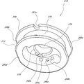
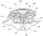
도 2는 끈 조임 시스템(100) 또는 다른 끈 조임 시스템과 유사할 수 있는 끈 조임 시스템(200)의 사시도이다. 끈 조임 시스템은 릴(104) 또는 여기에서 설명되는 임의의 다른 릴과 유사할 수 있는 릴(204)을 포함할 수 있다. 도 3은 릴(204)의 전개 사시도이다. 도 4는 릴(204)의 다른 전개 사시도이다.2 is a perspective view of a
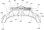
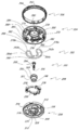
도 2 내지 도 4를 참조하면, 릴(204)은 베이스 부재(214), 스풀(216), 및 손잡이 부재(218)를 포함할 수 있다. 베이스 부재는 하우징(220)과 장착 플랜지(222)를 포함할 수 있다. 하우징(220)은 복수의 하우징 치(224)를 포함할 수 있고, 복수의 하우징 치(224)는 반경 방향 내측으로 연장될 수 있다. 하우징(220)은 끈(206)이 하우징(220)으로 들어가는 것을 허용하는 끈 구멍들(226a-b)을 포함할 수 있다. 2 to 4, the
스풀(216)은 하우징(220) 내에 배치될 수 있고, 스풀(216)은 축선(228) 주위에서 하우징(220)에 대하여 회전 가능하다. 끈(206)은 스풀(216)에 튼튼하게 고정될 수 있고, 스풀(216)이 (화살표 A로 도시된) 조이는 방향으로 회전할 때 끈(206)이 하우징 내부로 당겨져서 스풀(216)에 형성된 채널(230) 주위로 감겨지고, 스풀(216)이 (화살표 B로 도시된) 풀리는 방향으로 회전할 때 끈(206)은 스풀(216)의 채널(230)에서 풀리고 끈 구멍들(226a-b)을 통하여 하우징(220)에서 나가게 된다. 스풀(216)은 또한 스풀에 형성된 스풀 치들(232)을 포함할 수 있다. 여기에 개시된 실시 예들은 화살표 B로 도시된 방향으로의 회전이 끈 조임 시스템을 조이고 화살표A로 도시된 방향으로의 회전이 끈 조임 시스템을 풀리게 하도록 변형될 수 있다.
손잡이 부재(218)는 하우징(220)에 부착될 수 있고 손잡이 부재(218)는 축선(228) 주위로 하우징(220)에 대하여 회전할 수 있다. 손잡이 부재(218)는 스풀 치들(232)과 짝을 이루어서 손잡이 부재(218)를 스풀(216)과 연결하도록 구성된 손잡이 치들(234)을 포함할 수 있고, 손잡이 부재(218)가 조이는 방향으로의 회전할 때 스풀 (216)도 또한 조이는 방향으로 회전하도록 한다. 몇몇 실시예에 있어서, 풀리는 방향으로의 손잡이 부재(218)의 회전은 또한 스풀(216)을 풀리는 방향으로 회전하도록 할 수 있다. 손잡이 부재(218)는 또한 하우징 치들(224)과 맞물림 짝을 이루도록 반경 방향 외측으로 편향될 수 있는 하나 또는 그 이상의 폴들(236)을 포함할 수 있다. 폴들(236) 및 하우징 치들(224)은 손잡이 부재(218)가 조이는 방향으로 회전할 때 하우징 치들(224)이 폴들(236)을 반경 방향 내측으로 이동시키도록 구성될 수 있고, 그것에 의해서 손잡이 부재(218)가 조이는 방향으로 회전하는 것을 허용하도록 한다. 폴들(236) 및 하우징 치들(224)은 또한 힘이 가해져서 손잡이 부재(218)를 풀리는 방향으로 돌릴 때 그들이 서로 구속되도록 구성될 수 있고, 그것에 의해서 손잡이 부재(218)가 풀리는 방향으로 회전하는 것을 방지하게 된다.The
그러므로, 릴(204)은 사용자가 손잡이 부재(218)를 조이는 방향으로 회전시키도록 허용하는 일 방향 조임 시스템(one-way tightening system)을 제공할 수 있게 하며, 그것은 스풀(216)을 조이는 방향으로 회전하도록 하고, 그것은 결국 끈(206)이 끈 구멍들(226a-b)을 통하여 하우징 내부로 당겨지도록 한다. 끈(206)이 하우징(220) 내부로 감겨짐에 따라서 끈 조임 시스템(200)은 조일 수 있게 되고, 끈 가이드(208)를 릴(204)을 향하는 방향(도 2에서 화살표 C로 도시된)으로 당겨지도록 한다. 끈 조임 시스템(200)이 단일의 끈 가이드(208)와 함께 도시되어 있으나, 임의의 다른 적합한 수의 끈 가이드들이 사용될 수 있다.Therefore, the
몇몇 실시예에 있어서, 손잡이 부재(218)는 제1 위치 또는 제1 구속위치와 제2 위치 또는 제2 구속위치 사이에서 축선(228)을 따라서 축 방향으로 이동이 가능할 수 있다. 도 5는 릴(204)의 측면도로서, 손잡이 부재(218)가 해제된 위치에서 실선으로 도시되어 있고 구속된 위치에서 점선으로 윤곽이 나타나도록 도시되어 있다. 구속된 위치에 있을 때, 앞에서 기술된 것과 같이, 스풀 치들(232)은 손잡이 부재(218)를 스풀(216)에 연결하도록 손잡이 치들(234)과 맞물려 구속될 수 있다. 또한, 구속된 위치에 있을 때, 폴들(236)은, 앞에서 설명된 것과 같이, 손잡이 부재(218)가 조이는 방향으로 회전하는 것을 허용하면서 손잡이 부재(218)가 풀리는 방향으로 회전하는 것을 방지하도록 하우징 치들(244)과 맞물려 구속될 수 있다.In some embodiments, the
구속이 해제된 위치에 있을 때, 손잡이 부재(218)는 축 방향으로 베이스 부재(214)로부터 일정 거리 떨어져서 위치될 수 있고, 일정 거리는 손잡이 치들(234)을 들어올려서 떨어지도록 하고 스풀(216)이 손잡이 부재(218)로부터 분리되고 스풀(216)이 손잡이 부재(218)와 별도로 자유롭게 회전하도록 스풀 치들(232)을 해제하기에 충분한 거리이다. 그러므로, 끈(206)은 스풀(216)이 풀리는 방향으로 회전할 때 하우징(220)으로부터 인출될 수 있고 끈 조임 시스템(200)을 느슨하게 한다. 구속이 해제된 위치에 있을 때, 손잡이 부재(218)의 폴들(236)은 하우징 치들(224)로부터 들어 올려져서 구속이 해제되고 손잡이 부재(218)는 제한 없이 조이는 방향과 풀리는 방향 모두로 자유롭게 회전할 수 있다. 몇몇 실시예에 있어서, 손잡이 부재(218)가 구속이 해제된 위치로 이동되었을 때, 손잡이 치들(234)은 스풀 치들(232)로부터 구속이 해제되고 또한 폴들(236)도 하우징 치들(224)로부터 구속이 해제된다. 몇몇 실시예에 있어서, 손잡이 부재(218)가 구속이 해제된 위치로 이동되었을 때, 손잡이 치들(234)은 폴들(236)이 하우징 치들(224)과 계속 구속되어 있는 동안에 스풀 치들(232)로부터 구속이 해제된다. 몇몇 실시예에 있어서, 손잡이 부재(218)가 구속이 해제된 위치로 이동되었을 때, 손잡이 치들(234)은 스풀 치들(232)과 구속을 유지하나 폴들(236)은 하우징 치들(224)로부터 구속이 해제된다.When the restraint is in the released position, the
손잡이 부재(218)의 구속된 위치와 구속이 해제된 위치 사이의 거리(238)는 적어도 대략 1 mm 및/또는 대략 3 mm 이하이고, 몇몇 실시예에 있어서 대략 2.25mm 일 수 있으며, 이러한 범위 밖의 거리들도 또한 사용될 수 있다. 몇몇 실시예에서, 거리(238)는 스풀 치들(232)의 높이, 손잡이 치들(234)의 높이, 하우징 치들(224)의 높이, 및/또는 폴들(236)의 높이보다 약간 크거나 거의 정확하게 같을 수 있다.The
몇몇 실시예에 있어서, 폴들(236)은 하우징 치들(224)을 반경 방향에서 구속하고 손잡이 부재(218)는 구속된 위치와 구속이 해제된 위치 사이에서 축 방향으로 이동이 가능하기 때문에, 릴(204)은 우연적인 구속의 이탈에 대하여 저항력이 있다. 손잡이 부재가 구속된 위치에 있을 때, 그리고 힘이 가해져서 손잡이 부재(218)를 풀리는 방향으로 회전시키려고 하거나, 끈이 팽팽하게 당겨져서 스풀(218)을 풀리는 방향으로 회전시키려고 하면, 폴들이 하우징 치들(224)과 구속되어 있기 때문에 힘이 폴들(236)에게 작용된다. 폴들(236)은, 축선 방향이 아니라, 반경 방향으로 움직이도록 구성되어 있기 때문에, 실질적으로 폴들(236)에게 작용된 힘의 어느 것도 축선 방향으로 전달되지 않는다. 그러므로, 릴(204)은 손잡이 폴들이 하우징 치들과 축선 방향으로 구속된 몇몇 릴들보다 높은 조임 압력에 대하여 저항할 수 있다.In some embodiments, because the
도 6은 베이스 부재(214)의 사시도이다. 도 7은 베이스 부재(214)의 평면도이다. 도 8은 베이스 부재(214)의 저면도이다. 도 9는 베이스 부재(219)의 단면도이다. 베이스 부재(214)는 발 착용구 또는 다른 물품의 외측 구조물에 장착될 수 있는 장착 플랜지(222)를 포함하고, 장착 플랜지(222)의 적어도 일부가 은폐되어 보이지 않도록 장착 플랜지(22)는 물품의 외측 구조물의 하부에 장착될 수도 있다. 장착 플랜지(222)는 바느질, 또는 접착제나 리벳 등과 같은 임의의 다른 적당한 방법으로 물품에 견고하게 고정될 수 있다. 장착 플랜지(222)는 물품의 특정한 부분(예를 들면 신발의 뒤꿈치)에 적합하도록 윤곽을 구비하거나, 다양한 형상에 고정될 수 있도록 유연할 수 있다. 장착 플랜지(222)는 하우징(220)의 둘레 주위로 완전히 또는 부분적으로 연장될 수 있다. 장착 플랜지(222)는 사용 중에 물품의 구부러짐을 수용하도록 어느 정도 탄성을 구비할 수 있다. 몇몇 실시예에 있어서, 장착 플랜지(222)는 생략될 수 있고, 베이스 부재(214) 또는 하우징(220)은 스크류나 리벳 또는 다른 파스너로 물품에 장착될 수 있다. 예를 들면, 베이스 부재(214) 또는 하우징(220)의 나사산이 형성된 부분이 물품의 나사산이 형성된 대응 커넥터에 나사 결합 될 수 있다. 몇몇 실시예에 있어서, 장착 플랜지(222)는 물품에 연결되고 릴(204)이 나중에 플랜지(222)에 부착될 수 있다.6 is a perspective view of the
하우징(220)은 장착 플랜지(222)에 부착되거나, 일체로 함께 형성될 수 있고 도시된 것과 같이, 위를 향하여 연장될 수 있다. 하우징(220)은 함몰부(242)를 둘러싸는 외측벽(240)을 포함할 수 있고, 형상이 실질적으로 원형일 수 있다. 축(244)은 함몰부(242)의 바닥에서 축선 방향 상부로 연장될 수 있고, 축(244)은 함몰부(242)와 실질적으로 동축이 되도록 정렬될 수 있다. 축(244)은 축(244)이 함몰부(242)의 바닥과 만나는 단부(245) 또는 경사부를 포함할 수 있다. 축(244)은 중심에 손잡이 부재(218)를 하우징(220)에 고정하는 것을 용이하게 할 수 있는 보어(246)를 포함할 수 있다. 보어(246)에는 나사산이 형성되거나 그렇지 않으면 내부로 삽입되는 파스너(fastener)를 축방향에서 고정할 수 있도록 구성될 수 있다. 축(244)은 스풀(216)이 주위로 회전할 수 있는 지지면이 형성될 수 있다.The
하우징(220)의 외측벽(240)은 실질적으로 실린더 형상이 될 수 있고 축(244)과 실질적으로 동심이 될 수 있다. 외측벽(240)의 내측면은 하부(248)와 상부(250)를 포함할 수 있다. 하부(248)는 대체로 매끄럽고 외측벽(240)이 함몰부(242)의 바닥과 만나는 단부(251) 또는 경사부를 포함할 수 있다. 하부(248)는 끈(260)이 하우징(220)을 통과하여 함몰부(242)로 들어가도록 채널들(254a-b)에 의해서 끈 구멍들(226a-b)에 연결될 수 있는 하나 또는 그 이상의 개구들(252a-b)을 포함할 수 있다. 도 9에 잘 도시된 것과 같이, 끈 구멍들(226a-b)에 가장 근접한 끈 채널들(254a-b)의 하부는 잠길 수 있으며 반면에 끈 구멍들(252a-b)에 가장 근접한 끈 채널들(254a-b)의 상부는 맨 위에서 개방될 수 있다. 또한, 끈 채널들(254a-b) 및/또는 끈 구멍들(226a-b)은 하우징(220)의 바닥에 형성된 개구들(256a-b)에 연결될 수 있다. 개구들(256a-b) 및 채널들(254a-b)의 개방된 상부들은 사용과 설치 중에 끈(206)에 접근을 제공하고, 또한 사용 중에 함몰부(242)로 들어올 수 있는 물 또는 다른 물질을 위한 배출 통로를 제공할 수 있고, 베이스 부재(214)를 소수의 부품으로(예를 들면 일체화된 단일 조각으로) 제조될 때 끈 채널들(254a-b)의 성형을 용이하게 할 수 있다.The
하우징(220)은 외측벽(240)의 상부(250)에서 반경 방향 내측으로 연장되는 하우징 치들(224)을 포함할 수 있다. 도시된 실시 예에 있어서, 하우징은 36개의 하우징 치들(224)을 포함하고 있으나, 임의의 다른 적당한 수의 하우징 치들(224)이 사용될 수 있다. 도 7에 잘 나타난 것과 같이, 각각의 하우징 치들(224)은 제1측면(258)과 제2측면(260)을 포함할 수 있다. 제1측면(258)은 제2측면(260)보다 짧을 수 있고, 몇몇 실시예에 있어서, 제1측면(258)은 제2측면(260)의 대략 절반의 길이가 될 수 있다. 몇몇 실시예에 있어서, 하우징 치들(224)의 제1측면(258)은 길이가 적어도 대략 0.5mm 및/또는 1.0mm 이하가 되거나, 대략 0.85mm가 될 수 있고, 제2측면은 길이가 대략 1.0 mm 및/또는 2.0mm 이하가 되거나, 대략 1.75mm가 될 수 있다. 이러한 특정한 범위 이외의 다른 치수들도 또한 가능하다. 하우징 치들(224)의 제1측면(258)은 반경 방향 내측을 똑바로 향하는 선으로부터 어떤 각도(262) 만큼 경사질 수 있고 각도(262)는 적어도 대략 5 °및/또는 대략 최대 15가 될 수 있고, 몇몇 실시예에 있어서는 대략 10 °가 될 수 있다. 하우징 치들(224)의 제2측면(260)은 반경 방향 내측을 똑바로 향하는 선으로부터 어떤 각도(264) 만큼 경사질 수 있고 각도(262)은 적어도 대략 45 °및/또는 65 °이하가 될 수 있고, 몇몇 실시예에 있어서는 대략 55 °가 될 수 있다. 이러한 특정한 범위 이외의 다른 각도들도 또한 가능하다. 몇몇 실시예에 있어서, 하우징 치들(224) 사이의 변이부 및 하우징 치들(224)의 제1측면 및 제2측면(258, 260) 사이의 변이부는 곡선이 될 수 있고, 그러나 예리한 변이부도 또한 사용될 수 있다. 하우징 치들(224)은 아래에서 매우 상세히 설명되는 것과 같이 폴들(236)과 접촉되도록 구성될 수 있다. 하우징 치들(224)은 아래에서 매우 상세히 설명되는 것과 같이 폴들(236)이 구속이 해제된 위치에서 구속된 위치로 이동하는 것을 용이하게 하는 각이진 상부 표면들(226)을 포함할 수 있다.The
베이스 부재(214)는 하우징(220)의 외측벽(240)보다 축선 방향 상부를 향하여 더 연장될 수 있는 하나 또는 그 이상의 보호편들(guard pieces)을 포함할 수 있고 보호편(268)은 손잡이 부재(218)가 하우징(220)에 부착될 때 손잡이 부재(218)의 일부를 덮는 기능을 할 수 있다. 몇몇 실시예에 있어서, 보호편(268)은 생략될 수 있다. 몇몇 실시예에 있어서, 릴(204)은 물품의 들어간 부분 안에 배치될 수 있고 물품 자체의 일부분이 손잡이 부재(218)의 일부를 덮도록 연장될 수 있다. 보호편(268), 또는 보호편으로 작용하는 물품의 일부분은 손잡이 부재(218)를 보호하고 손잡이 부재(218)가 우연히 분리되는 것을 줄일 수 있다.The
도 10A는 스풀(216)의 사시도이다. 도 11은 스풀(216)의 다른 사시도이다. 도 12는 스풀(216)의 측면도이다. 도 13A-B는 끈(206)이 부착된 스풀(216)의 횡단면 저면도이다. 도 14는 하우징(220) 내에 배치된 스풀(216)의 평면도이다.10A is a perspective view of the
스풀(216)은 상부플랜지(270) 및 하부플랜지(272)를 포함할 수 있고 그들 사이에 실질적으로 실린더 형상의 벽(274)이 형성되어 있다. 벽(274)의 외측면, 상부 플랜지(270)의 바닥면, 및 하부 플랜지(272)의 상부면은 끈(206)이 스풀(216) 주위로 감겨질 때 이를 수집하기 위한 채널(230)을 형성할 수 있다. 벽(274)의 내측면은 스풀 부재(216)의 바닥에 형성된 함몰부(276)를 둘러쌀 수 있다. 중앙 개구(278)는 함몰부의 천장을 관통하여 연장될 수 있다. 도 14에 잘 도시된 것과 같이, 스풀(216)이 하우징(220)의 함몰부(242) 내에 배치되어 있을 때, 축(244)은 스풀(216)의 중앙 개구(278)를 통하여 통과할 수 있다. 단부(245) 또는 축(244)의 바닥에서 경사진 모서리는 스풀(216)의 바닥에 형성된 함몰부(276) 내부로 수용될 수 있다. 하부 플랜지(272)는 상부 플랜지(270)보다 약간 작게 형성될 수 있으며(도 12에 잘 도시된 것과 같이) 하부 플랜지(270)는 단부(252) 또는 함몰부(242)이 가장자리의 계단부(251)나 경사진 가장자리 안에 끼워질 수 있고, 끈(206)이 부착된 채로 스풀(216)을 하우징(220)으로부터 제거하거나 및/또는 하우징(220) 내에 설치하는 것을 용이하게 할 수 있다. 그러므로, 몇몇 실시예에 있어서, 하부 플랜지(272)의 바닥면은 함몰부(242)의 베이스와 접하도록 놓여 질 수 있다. 몇몇 실시예에 있어서, 하우징(220)의 일부는 스풀(216)의 일부와 접촉하도록 구성되어 스풀(216)이 회전할 때의 마찰을 줄이도록 하부 플랜지(272)의 바닥면이 함몰부의 베이스로부터 약간 떨어져 있도록 유지할 수 있다. 스풀(216)이 하우징(220의 함몰부(242) 내로 완전히 삽입될 때, 상부 플랜지(270)의 상부면은 외측벽(240)의 하부(248)의 윗면과 실질적으로 정렬될 수 있어서 상부 플랜지(270)가 하우징 치들(224)과 중첩되지 않게 된다.The
스풀 치들(232)은 스풀(216)의 상부면에 형성될 수 있다. 도시된 실시예에서, 12 개의 스풀 치들(232)이 도시되어 있으나, 임의의 다른 적당한 수의 스풀 치들(232)이 사용될 수 있다. 각각의 스풀 치들(232)은 제1측부(280) 및 제2측부(282)을 포함할 수 있다. 제1측부(280)는 몇몇 실시예에 있어서 실질적으로 수직이 될 수 있다. 몇몇 실시예에 있어서, 제1측부는 적어도 대략 5 °및/또는 대략 15 °이하 경사질 수 있고, 몇몇 실시예에 있어서 수직 평면으로부터 대략 10 °경사 질 수 있다. 제2측부(282)는 적어도 대략 35 ° 및/또는 대략 55 °이하 경사질 수 있고, 몇몇 실시예에 있어서 수직 평면으로부터 대략 45 °경사질 수 있다. 제1측부(280)는 길이가 적어도 대략 1.5 mm 및/또는 2.5 mm 이하일 수 있고, 길이가 대략 2.0 mm 일 수 있다. 제2측부는 길이가 적어도 대략 2.5 mm 및/또는 대략 3.5 mm 이하일 수 있고, 길이가 대략 3.0 mm 일 수 있다. 상기의 범위 밖의 치수들과 각도들이 또한 사용될 수 있다. 스풀 치들(232)은 여기에서 상세히 설명되는 것처럼 손잡이 치들(234)과 접촉되도록 구성될 수 있다.
몇몇 실시예에 있어서, 하나 또는 그 이상의 절결부들(281a-b)이 스풀(216)의 상부 플랜지(270)에 형성될 수 있다. 또한, 몇몇 실시예에 있어서, 상부 플랜지(270) 및/또는 하부 플랜지는 실질적으로 원형일 수 있으나, 하나 또는 그 이상의 평평한 가장자리들(283a-d)을 구비할 수 있다. 절결부들(282a-b) 및/또는 평평한 가장자리들(283a-d)은 스풀(216)을 하우징(220)으로부터 제거하는 것을 용이하게 할 수 있다(예를 들면, 끈(206)을 교체할 때). 스크류드라이버 또는 다른 도구가 스풀(216) 및 하우징(220) 벽 사이에 삽입될 수 있고 스풀(216)은 하우징(220)으로부터 뽑혀 질 수 있다. 많은 변형들이 가능하다. 예를 들면, 도 10B는 스풀(216')의 상부 플랜지(270') 및 하부 플랜지(272')가 평평한 가장자리들(283a-d)을 구비하지 않은 점을 제외하고 스풀(216)과 많은 측면에서 유사한 스풀(216')의 사시도이다. 그러므로, 상부 플랜지(270') 및 하부 플랜지(272')는 실질적으로 원형일 수 있다. 몇몇 실시예에 있어서, 상부 플랜지(270')는 하우징(220)으로부터 스풀(216')을 제거하는 것을 용이하게 할 수 있는 절결부들(281a' 및 281b')을 포함할 수 있다. 몇몇 실시예에 있어서, 평평한 가장자리들(283a-d)를 포함하지 안흔 플랜지들(270' 및 272')은, 특히 상대적으로 가는 끈이 사용될 때, 끈(206)이 하우징(220)과 평평한 가장자리들(283a-d) 사이에 형성되는 틈들에 걸리거나 끼이게 되는 것을 방지할 수 있다.In some embodiments, one or
채널(230)의 깊이는 적어도 대략 1.5 mm 및/또는 대략 2.5 mm 이하일 수 있고, 몇몇 경우에 대략 2.0 mm 일 수 있다. 채널(230)은 적어도 대략 3.0 mm 및/또는 대략 4.0 mm 이하의 폭을 갖을 수 있고, 몇몇 경우에 대략 3.5 mm 의 폭을 갖을 수 있다. 벽(274)의 외측면은 적어도 대략 10 mm 및/또는 대략 20 mm의 직경을 구비할 수 있고, 몇몇 경우에 대략 14 mm의 직경을 갖을 수 있다. 주어진 범위들 밖의 치수들도 또한 가능하다. 끈(206)은 대체로 직경이 충분히 작아서 채널(230)이 적어도 대략 300 mm의 끈 및/또는 대략 600 mm 이하의 끈을 수용할 수 있고, 몇몇 실시예에 있어서 대략 450 mm의 끈을 수용할 수 있으며, 스풀(216) 및 끈(206)은 이러한 주어진 범위들 밖의 끈을 수용하도록 구성될 수도 있다.The depth of the
끈 또는 케이블은 적어도 대략 0.5 mm 및/또는 1.5 mm 이하의 직경을 구비할 수 있고, 몇몇 실시예에 있어서 직경은 대략 0.75 mm 또는 1.0 mm 일 수 있고, 또한 이러한 범위들 밖의 직경들도 사용될 수 있다. 끈(206)은 저 탄성 계수 및 고 인장 강도를 갖는 매우 매끄러운 케이블 또는 섬유일 수 있다. 몇몇 실시예에 있어서, 케이블은 함께 꼬여진 재질의 복수의 가닥을 구비할 수 있다. 임의의 적당한 끈이 사용될 수 있으나, 몇몇 실시예는 연장 사슬 고 강도 폴리에틸렌 섬유(extended chain, high modulus polyethylene fibers)로 형성된 끈을 이용할 수 있다. 적당한 끈 재료의 일 실시예가 뉴저지 모리스 타운쉽의 하이웰에 의해서 제조된 상품명 SPECTRATM 라는 이름으로 팔리고 있다. 연장 사슬 고 강도 폴리에틸렌 섬유들은 유리하게 높은 중량 대 강도 비를 갖고, 절단 저항이 높으며, 매우 낮은 탄성을 구비한다. 이러한 재질로 만들어진 바람직한 끈은 견고하게 꼬여진 것이다. 견고한 꼬임은 완성 끈에 부가의 빳빳함을 제공한다. 꼼에 의해서 제공되는 부가의 빳빳함은 향상된 밀기 능력을 제공하여, 끈이 용이하게 꿰어진다 (예를 들면, 릴(204) 안으로). 부가적으로, 몇몇 실시예에 있어서, 끈은 성형된 모노필라멘트 폴리머(a molded monofilament polymer)로 형성될 수 있다. 몇몇 실시예에 있어서, 끈은 폴리머 또는 다른 윤활제가 코팅되거나 코팅되지 않은 꼬여진 강선으로 만들어 질 수 있다.The strap or cable may have a diameter of at least approximately 0.5 mm and/or 1.5 mm or less, in some embodiments the diameter may be approximately 0.75 mm or 1.0 mm, and diameters outside these ranges may also be used. . The
끈(206)의 하나 또는 그 이상의 단부는 스풀(216)에 단단히 고정될 수 있다. 몇몇 실시예에 있어서, 끈(206)은 스풀(216)에 제거 가능하거나 고정되도록 부착될 수 있다. 몇몇 실시예에 있어서, 끈(206)은 스풀(216)에 형성된 구멍을 통과하여 꿰어질 수 있고 구멍으로부터 단부가 당겨져 빠지는 것을 방지하기 위하여, 끈(206)의 단부에 매듭이 형성되거나 정착 부재가 부착될 수 있다. 몇몇 실시예에 있어서, 끈(206)은 스풀(216)의 일부분에 묶여 질수 있다. 끈은 또한 스풀(216)에 접착제나 다른 적당한 방식으로 단단히 고정될 수 있다. 몇몇 실시예에 있어서, 끈(206)은 스풀(216)에 일련의 개구들을 통과하게 얽어서 단단히 고정할 수 있고 개구들은 끈(206)이 스풀(206)로부터 빠지는 것을 방지하기에 충분한 마찰이 생기도록 하는 각도로 끈(206)을 감기게 한다. 몇몇 실시예에 있어서, 끈(206)은 당겨졌을 때 끈(206) 자신을 팽팽하게 하도록 겹쳐진다. 몇몇 실시예에 있어서, 끈(206)의 단지 한쪽 단부만이 스풀(216)에 단단히 고정되고, 끈(206)의 다른 단부는 베이스 부재(214) 또는 조여지는 물품에 단단히 고정된다.One or more ends of the
스풀(216)은 끈(206)의 제1 단부를 단단히 고정하도록 구성된 제1 끈 구멍들 세트(284a, 286a, 288a)를 포함할 수 있다. 몇몇 실시예에 있어서, 제2 끈 구멍들 세트(284b, 286b, 288b)가 끈(206)의 제2 단부를 단단히 고정하기 위하여 사용될 수 있다. 끈 가이드들(290a-b)이 또한 끈(206)을 스풀(216)에 단단히 고정하는 것을 용이하게 하기 위하여 함몰부(276)에 형성될 수 있다.The
도 13A에 도시된 실시예에 있어서, 끈(206)의 제1 단부는 끈 구멍(284a)를 통과하여 함몰부(276) 안으로 빠져나갈 수 있다. 끈 가이드(290a)는 끈(206)이 끈 구멍(286a)을 향하도록 방향을 돌릴 수 있고, 몇몇 실시예에 있어서, 끈 가이드(290a)는 끈(206)이 끈 가이드(290a)와 벽(274)의 일부분(292a) 사이에 끼이도록 구멍들(284a 및 286a) 사이에 배치될 수 있다. 끈(206)은 끈 구멍(286a)을 통과하여 함몰부(276)를 나가서 끈 구성(288a)를 통과하여 다시 함몰부(276)로 들어가도록 대략 180 ° 의 각도로 방향을 돌릴 수 있다. 몇몇 실시예에 있어서, 끈(206)의 제1 단부의 끝은 대향하는 끈 가이드(290b)에 밀어 넣어져서 끝이 함몰부(276) 내에서 이리저리 움직이는 것과 스풀(216)의 회전과 간섭하는 것을 방지할 수 있다. 몇몇 실시예에 있어서, 끈 구멍들(284a, 286a, 288a)을 통과하는 끈(206)의 양은 끈(206)의 단지 적은 부분만이 구멍(288a)을 통과하여 함몰부(276)로 다시 들어가도록 구성되어 끈의 끝이 대향하는 끈 가이드(290b)로 밀어 넣어지지 않게 된다. 끈(206)의 제2 단부는 끈 구멍들(284a, 286b, 288b), 끈 가이드(290b), 그리고 벽(274)에 의해서 비슷한 방식으로 스풀(216)에 단단히 고정될 수 있다.In the embodiment shown in FIG. 13A, the first end of the
다른 끈 고정 구성들이 가능하다. 예를 들면, 도 13B에 도시된 실시예에 있어서, 끈(206)의 제1단부는 끈 구멍(284a)을 통과하여 함몰부(276)에 들어간다. 끈 가이드(290)는 끈(206)이 끈 구멍(288b)을 향하여 방향을 돌리도록 하고, 끈 가이드(290a)는 끈(206)이 끈 가이드(290a)와 끈 구멍(284a)에 인접한 벽의 부분(294a) 사이에 끼이도록 구성될 수 있다. 끈(206)은 끈 구멍(288b)을 통하여 지나가고 끈 구멍(286b)을 통과하여 함몰부(276)로 다시 들어가도록 대략 180의 각도로 회전할 수 있다. 끈(206)의 제2 단부는 스풀(216)에 끈 구멍들(284b, 288a, 286a), 끈 가이드(290b) 및 벽(274)의 부분(294b)에 의해서 같은 방식으로 단단히 고정될 수 있다.Other strap fixing configurations are possible. For example, in the embodiment shown in FIG. 13B, the first end of the
도 13C 및 13D는 끈(206)이 스풀(216)에 단단히 고정될 수 있는 다른 방식을 도시한다. 도 13C에 도시된 것과 같이, 끈(206)의 단부는 끈 구멍(284a)을 통하여 함몰부(276) 안으로 꿰어지고, 끈 구멍(286a)을 통하여 함몰부(276)로부터 꿰어지고, 끈 구멍(288a)을 통하여 함몰부(276) 안으로 다시 꿰어진다. 끈(206)의 단부는 도 13C에 도시된 것과 같이, 끈 구멍들(284a, 286a) 사이에서 끈에 형성된 고리를 통과하여 지나간다. 그리고 끈(206)은 도 13D에 도시된 것과 같이 끈이 그 자신 아래로 교차되도록 하여 팽팽히 조여질 수 있다. 예를 들면, 끈(206)의 헐거운 단부는 끈 구멍들(286a 및 288a) 사이에서 형성된 고리로부터 느슨함을 제거하기 위하여 끈 구멍들(284a 및 286a) 사이에 형성된 고리를 당기는 동안에 한 손에 쥐어 질 수 있다. 그리고 끈 구멍들(284a 및 286a) 사이에 형성된 고리의 헐거움은 끈이 자신을 팽팽하게 조일 때까지 끈 구멍(284a)를 통하여 함몰부(276)로 밖으로 당겨질 수 있다. 그러므로, 일단 조여지면, 끈(206)은 당겨질 때 더욱 단단히 자신을 누르게 되고, 그것에 의해서 끈(206)이 스풀(216)로부터 분리되는 것을 방지한다.13C and 13D show another way the
끈(206)은 도시된 것과 같이, 끈 구멍(288a)에 가장 근접한 고리 부분의 상부를 통과하여 끈 구멍(288a)으로부터 가장 먼 고리 부분의 하부를 통과할 수 있다. 그리고, 끈 이 조여졌을 때, 끈(206)의 헐거운 단부는 대체로 함몰부(276)의 베이스를 향하도록 방향이 돌려질 수 있다. 그러나 만약 끈이 끈 구멍(288a)으로부터 가장 먼 고리의 부분이 상부로 꿰어진 경우 대체로 함몰부(276)에서 외부로 향하도록 방향이 돌려질 것이다. 끈(206)의 헐거운 단부를 함몰부(276)의 베이스를 향하여 편향시켜서, 끈의 헐거운 단부가 하우징(220) 내에 삽입되는 스풀(216)과 간섭되는 것을 방지할 수 있다. 끈 가이드(190a)는 끈(206)의 헐거운 단부를 함몰부(276)의 가장자리 근방에 위치하게 유지하도록 배치될 수 있어서 끈(206)의 헐거운 단부가 중앙 개구(278)로 들어가지 않도록 하거나 하우징(220)에 삽입되는 스풀(216)과 간섭되지 않도록 한다.The
도 15는 손잡이 부재(218)의 전개 사시도이다. 도 16은 손잡이 부재(218)의 다른 전개 사시도이다. 손잡이 부재(218)는 손잡이 코어(296), 폴들(236), 스프링 부싱(298), 패스너(300), 손잡이 스프링(302), 손잡이 커버(304) 및 손잡이 그립(306)을 포함한다.15 is an exploded perspective view of the
손잡이 코어(296)는 대체로 디스크 형상이 될 수 있다. 손잡이 코어(296)는 바닥 표면에 형성된 손잡이 치들(234)을 포함할 수 있다. 도시된 실시예에 12 개의 손잡이 치들(234)이 도시되어 있으나, 다른 임의의 적당한 수의 손잡이 치들(234)이 사용될 수 있다. 몇몇 실시예에 있어서, 같은 수의 손잡이 치들(234) 및 스풀 치들(232)이 사용될 수 있고, 손잡이 치들(234)이 스풀 치들(232)과 맞물릴 수 있도록 반대 방향으로 방향이 형성된 것을 제외하고 손잡이 치들(234)의 형상은 스풀 치들(232)과 동일하거나 유사할 수 있다. 따라서, 스풀 치들(232)과 관련하여 앞에서 설명된 치수들은 또한 손잡이 치들(234)에 적용이 가능하다. 손잡이 부재(218)가 조이는 방향으로 회전될 때, 손잡이 치들(234)의 제1측부들(308)은 조이는 방향으로 스풀(216)을 구동하도록 스풀 치들(232)의 제1측부들(280)을 누를 수 있다. 끈(206)이 스풀(216) 주위에 팽팽하게 조여져 있을 때 스풀(216)이 풀리는 방향으로 회전하도록 스풀(216)에 힘을 가하면, 스풀 치들(232)의 제2측부들(282)은 손잡이 치들(234)의 제2측부들(310)을 누를 수 있고 힘이 손잡이 부재(218)에 전달되어 손잡이 부재가 풀리는 방향으로 회전하게 한다. 아래에서 설명되는 것과 같이, 힘은 손잡이 부재(218) 및 스풀(216)이 풀리는 방향으로 회전하는 것을 방지하기 위하여 폴들(236)이 하우징 치들(224)과 결합되도록 하고, 그것에 의해서 끈(206)이 조여진 형태를 유지한다.The
손잡이 코어(296)는 손잡이 커버(304)를 고정을 용이하게 하기 위한 특징부들을 포함할 수 있다. 손잡이 코어(296)는 손잡이 코어(296)의 가장자리 근방 상부면에 형성된 노치들(312)을 포함할 수 있다. 돌기들(314)은 노치들(312) 아래 위치들에서 손잡이 코어(296)의 가장자리로부터 반경 방향 외측으로 연장될 수 있다. 손잡이 코어(296)는 중심을 통과하는 중앙 개구(316)를 포함할 수 있고, 스프링 부싱(298)을 수용하도록 구성될 수 있다. 중앙 개구(316)의 상부 부분은 중앙 개구(316)의 하부 부분보다 넓을 수 있고 그 안에 계단(318)을 형성한다. 손잡이 코어(296)는 또한 손잡이 스프링의 고정을 용이하게 하기 위한 특징부들, 예를 들면, 넓은 구속 탭(320) 및 좁은 구속 탭(322)을 포함하는 특징부들을 포함할 수 있다.The
손잡이 코어(296)는 또한 폴 함몰부들(324)을 포함 할 수 있고, 대응하는 폴들(236)을 수용하도록 구성되어 있다. 폴 함몰부들(324)은 대체로 폴들(236)과 유사한 형상으로 될 수 있으나, 다른 곳에서 보다 상세히 설명된 것과 같이, 작동 중에 폴들(236)이 선회하여 폴 함몰부들(324) 내로 이동하는 것을 허용하도록 폴들(236)보다 약간 클 수 있다. 폴 함몰부들(324)은 그것들의 베이스 및/또는 측부의 부분에 형성된 폴 개구들(326)을 포함할 수 있고, 폴들의 일 부분(예를 들면 폴 치들)이 손잡이 코어(296)을 통과하여 연장되고(도 4의 조립된 손잡이 부재(218)에서 볼 수 있는 것과 같이) 하우징 치들(224)과 접촉되는 것을 허용한다.
도 17 및 도 18은 폴(236)의 사시도들이다. 폴(236)은 폴 베이스(328)와, 폴 빔(330)과, 폴 스프링(332)를 포함할 수 있다. 폴 베이스(328)는 폴(236)이 축선(334) 주위로 선회할 수 있도록 손잡이 코어(296) 및/또는 손잡이 커버(304)와 접속되도록 구성될 수 있다. 피봇 탭(336)은 축선(334)을 따라서 폴 베이스(328)로부터 위로 연장될 수 있다. 피봇 탭(336)은 실질적으로 실린더 형상일 수 있고 축선(334)과 동축이 될 수 있다. 플랜지(337)는 폴 베이스(328)의 일측으로부터 외측으로 연장되고, 플랜지(337)는 폴(236)의 선회를 용이하게 할 수 있다. 도 17 및 도 18에서 볼 수 있는 것과 같이, 몇몇 실시예에 있어서, 폴 빔(330), 폴 스프링(332), 및 폴(236)의 다른 부품들은 단일 조각으로 일체로 형성될 수 있다(예를 들면 성형되어).17 and 18 are perspective views of
폴 빔(330)은 손잡이 부재(218)가 조이는 방향으로 회전되었을 때 하우징 치들(224)에 의해서 폴(236)이 이동될 경우 휘어지지 않을 정도로 실질적인 강체가 될 정도의 재료, 두께, 및 길이로 형성될 수 있다. 하나 또는 그 이상의 폴 치들(338a-b)은 폴 베이스(328)의 반대측 폴 빔(330)의 단부 근처에 배치될 수 있다. 도시된 실시예에 있어서, 두 개의 폴 치들(338a-b)이 사용되나, 다른 적당한 수의 폴 치들(338a-b)이 대신 사용될 수 있다. 폴 치들(338a-b), 및 몇몇 경우에 있어서 전체 폴 빔(330)은, 여기 다른 곳에서 상세히 설명된 것과 같이, 손잡이 부재(218)가 구속된 위치에서 구속이 해제된 위치로 이동하는 것을 용이하게 할 수 있는 각이 형성되거나 경사진 바닥면(339)을 구비할 수 있다. 폴 빔(330)은 폴(236)의 받침부보다 하부로 연장되도록 폴 빔(300)의 단부에 형성된 계단(340)을 포함할 수 있다. 폴 빔의 하방으로 연장되는 부분은 손잡이 코어(296)의 폴 함몰부(324)에 형성된 폴 개구(326) 안으로 또는 관통하여 연장되도록 구성될 수 있다.The
폴 베이스(328)는 폴 함몰부(324)의 표면(324a)과 결합되도록 구성된 단부 표면(328a)을 포함할 수 있다(도 19에 도시된 것과 같이). 몇몇 실시예에 있어서, 압력이 하나 또는 그 이상의 폴 치들(338)에 가해질 때, 부하가 폴 빔(330)을 통하여 단부 표면(328a) 및 표면(324a)의 결합 부분에 전달될 수 있다. 몇몇 실시예에 있어서, 폴(236)이 축선(334)을 중심으로 반경 방향 외측으로 선회할 때, 폴 베이스(328)의 단부 표면(328a)은 폴 함몰부(324)의 표면(324a)과 맞닿을 수 있고, 그것에 의해서 폴(326)이 반경방향 외측으로 선회하는 거리를 제한하게 된다. 예를 들면, 폴(236)은 하우징 치들(224)을 구속하기에는 충분하나 그 이상은 선회하지 않도록 반경 방향 외측으로 선회하도록 허용될 수 있다. 이것은 손잡이 부재(218)에 풀리게 하는 힘이 작용되었을 때 폴들(236)에 걸리는 압력을 해제하게 할 수 있고, 아래에서 설명되는 것과 같이, 폴들(236)을 반경 방향 외측으로 미는 힘의 성분을 생성할 수 있다. 손잡이 부재(218)가 구속이 해제된 위치에 있을 때 표면들(328a 및 324a) 사이의 접촉은 또한 폴들(236)의 반경 방향 이동을 제한할 수 있고, 그것에 의해서 손잡이 부재(218)가 폴들(236)과 실질적으로 간섭되지 않고 구속된 위치로 가압되기에 충분하게 폴들(236)이 반경 방향 내측에 유지되도록 한다. 몇몇 실시예에 있어서, 폴(236)은 폴 함몰부(324)에 위치되고 대체로 손잡이 커버(304)와 손잡이 코어(296) 사이에 갇힌다. 아래에서 설명되는 것과 같이, 상부 탭들(384)은 폴(236)의 축방향 운동을 제한하기 위하여 피봇 탭(336)과 결합 될 수 있다. 유사하게, 손잡이 커버(304)로부터 하방으로 연장되는 빔 탭들(385)은 축 방향 이동을 억제하기 위하여 폴 빔(330)의 상부 면과 결합 될 수 있다.
폴 스프링(332)은 실시예에 도시된 것과 같이 외팔보(cantilever) 또는 아치형 스프링이 될 수 있으나, 임의의 다른 적당한 형태의 스프링이 사용될 수 있다. 폴 스프링(332)은 폴 빔(330)과 대체로 동일한 방향으로 폴 베이스(328)로부터 연장될 수 있다. 폴 스프링(332)은 폴 빔(330)으로부터 곡선으로 구부려 질 수 있다. 폴 스프링의 말단에 대체로 실린더 형상의 말단 편(342)이 형성될 수 있다. 손잡이 부재(218)가 조이는 방향으로 회전될 때 하우징 치들(224)에 의해서 폴(236)이 옮겨지면서 폴 스프링(332)이 휘어지도록 폴 스프링(332)은 탄성적으로 유연한 재질, 두께 및 길이로 형성될 수 있다. 폴 스프링(332)은 도 17 및 도 18에서 이완된 위치에서 도시되어 있다. 몇몇 실시예에 있어서, 폴 빔(330)과 폴 스프링(332)은 독립적으로 형성되고 폴(236)을 형성하도록 결합되었다. 그러므로 폴 빔(330)과 폴 스프링(332)은 동일한 재질로 형성될 필요는 없다. 예를 들면, 프라스틱 폴 스프링(332)을 사용하는 것이 유리한 반면에, 금속 폴 빔(330)이 두께에 비하여 비교적 높은 강성 비율을 구비하여 유리하다. 몇몇 실시예에 있어서, 폴 빔(330)과 폴 스프링(332)이 별도로 형성될 경우에도 각각에 동일한 재료가 사용될 수 있다. 도 17 및 도 18에 도시된 실시예에 있어서, 폴 스프링(332) 및 폴 빔(330)은 단일 조각으로 동일한 재료로 일체로 형성될 수 있고, 그것에 의해서 제조 및 조립 비용과 복잡성을 단순화한다. 몇몇 실시예에 있어서, 설명된 실시예들에 도시된 스프링 이외에 다른 스프링들이 사용될 수 있다. 예를 들면, 몇몇 적용예에서 금속 또는 플라스틱 판 스프링(leaf spring) 또는 철사 코일 스프링(wire coiled spring)이 사용될 수 있다.The
폴 빔(330) 및 폴 스프링(332)은 별도의 부분이므로, 폴 스프링(332)은 손잡이 부재(218)가 푸는 방향으로 회전될 때 폴 빔(330)이 버틸 수 있는 힘의 양을 줄이지 않고서 보다 용이하게 유연하도록(예를 들면, 폴 스프링(332)을 얇게 만들어서) 변경될 수 있다. 마찬가지로, 폴 빔(330)은 폴 스프링(332)을 덜 유연하게 만들지 않고 손잡이(218)에 풀리는 방향으로 작용된 큰 힘을 견딜 수 있도록(예를 들면 폴 빔(330)을 두껍게 만들어서) 변경될 수 있다. 이와 같이, 폴(236)은 바라는 수준의 유연성과 강도로 조절될 수 있다. 예를 들면, 폴(236)은 손잡이 부재(218)가 조이는 방향으로 회전될 때 용이하게 반경 방향으로 옮겨질 수 있으면서 또한 손잡이 부재(218)가 풀리는 방향으로 회전될 때 큰 힘을 견딜 수 있도록 구성될 수 있다. 몇몇 실시예에 있어서, 손잡이 부재(218)가 풀리는 방향으로 회전될 때 폴(236)에 작용된 힘은 폴 빔(330)에 의해서 생기고 실질적으로 어느 힘도 폴 스프링에 의해서 생기지 않는다. 이 구성은 폴을 옮기도록(예를 들면 조이는 동안에) 휘어지는 부하 지지 빔(load bearing beam)을 폴이 포함하는 실시예들에 있어서 유리할 수 있는 데, 유연한 폴의 부하지지 능력은 폴이 유연할수록 감소되고, 빔이 큰 힘들을 견디도록 만들어 질 때 폴의 유연성은 줄어들기 때문이다. 그러므로 유연한 빔 폴을 사용할 때, 충분한 크기의 푸는 힘은 폴 빔이 굽어지게 할 수 있고, 그것에 의해서 끈 조임 시스템을 손상시킨다. 그러나, 폴들(236)을 사용할 때, 폴 빔(330)은 비교적 큰 푸는 힘이 작용될 때에도 실질적으로 단단하게 구성될 수 있고, 폴 스프링(332)은 조이는 힘이 작용될 때 폴 빔(330)이 용이하게 선회하는 것을 허용하도록 구성될 수 있다.Since the
도 19는 손잡이 코어(296)의 폴 함몰부(324) 내부에 배치된 폴들(236)을 도시하는 평면도이다. 하우징(220)은 도 19에 도시되어 있지 않으나, 폴들(236)은 폴 치들(338a-b)이 하우징 치들(224)과 구속된 위치에서 도시되어 있다. 도 20은 폴 치들(338a-b)이 하우징 치들(224)과 구속된 상태로 도 19와 같은 위치에 있는 베이스 부재(214) 및 폴들(236)을 도시하는 평면도이다. 도 21은 손잡이 부재(218)가 조이는 방향으로 회전되었을 때 옮겨진 구성에 있는 베이스 부재(214) 및 폴들(236)의 평면도이다. 폴들(236)을 제외한 손잡이 부재(218)의 요소들, 및 스풀(216)은 단순화를 위하여 도 20 및 도 21에 도시된 도면에서 생략되었다.19 is a plan view showing the
몇몇 실시예에 있어서, 폴 스프링들(332)은 폴 함몰부들(324)에 삽입되었을 때 이완된 위치보다 덜 휘어지는 위치까지 부분적으로 휘어질 수 있다. 굽혀진 폴 스프링들(332)은 폴들(236)이 선회하도록 하여 폴 빔들(330)이 반경 방향 외측으로 편향되도록 하고 폴 치들(338a-b)이 하우징 치들(224)에 대하여 반경 방향 외측으로 누르게 한다. 손잡이 부재(218)가 풀리는 방향으로 회전될 때(화살표 B로 도시됨) 폴 치들(338a-b)의 제1측부들(344a-b)은 손잡이 부재(218)가 풀리는 방향으로 회전하는 것을 방지하기 위하여 하우징 치들(224)의 제1측부들(258)을 누를 수 있다. 몇몇 실시예에 있어서, 폴 함몰부들(324)은 폴 스프링들(332)이 부분적으로 휠 필요 없이 폴들(236)을 수용하도록 구성될 수 있다. 그러므로 몇몇 실시예에 있어서, 폴 스프링들(332)은 손잡이(218)가 풀리는 것을 방지하기 위하여 폴 빔들(330)이 하우징 치들(224)에 결합되어 있을 때 이완된 위치에 있을 수 있다. 폴 빔들(330)이 하우징 치들(224)로부터 떨어지도록 옮겨졌을 때, 폴 스프링들(332)은 폴 빔들(330)이 하우징 치들(224)을 향하여 편향되도록 이완된 상태에서 휘어진 상태로 이동할 수 있다. 또한, 도 20에 예로 도시된 것과 같이, 몇몇 실시예에 있어서, 하나 또는 그 이상의 폴 치들(338a-b)은 폴(236)의 피봇 축(334)으로부터 연장되는 접선의 반경 방향 외측에서 하우징 치들(224)과 맞물릴 수 있다. 도 20의 실시예에 있어서, 폴 치들(338b)은 대응하는 하우징 치들(224)과 접선 C로부터 어떤 각도(345) 만큼 반경 방향 외측으로 각이진 라인 상의 지점에서 맞물릴 수 있고, 그 각도는 적어도 대략 5 ° 및/또는 대략 15 ° 이하이거나, 몇몇 실시예에 있어서는 대략 10 °가 될 수 있다. 그러므로 손잡이 부재(218)에 풀리는 힘이 작용 되었을 때 (화살표 B도 도시됨), 힘의 어떤 성분은 폴(236)이 반경 방향 외측으로 선회하게 미는 방향으로 향하게 된다. 그러므로 손잡이 부재(218)에 더 큰 푸는 힘이 가해질 때, 폴 치들(338a-b)은 하우징 치들(224)과 더욱 견고하게 맞물리도록 밀리게 된다. 이것은 큰 푸는 힘이 작용되었을 때 폴들(236)이 하우징 치들(224)로부터 우연히 맞물림이 풀리는 것을 방지할 수 있다. 폴(236)이 반경 방향 외측으로 가압될 때, 폴 빔은 폴 치들(338a-b)에 의하여 맞물리지 않은 하나 또는 그 이상의 하우징 치들(224)의 말단들과 접촉할 수 있고, 이것은 폴 빔(330)이 외측으로 굽혀지는 것을 방지하고 푸는 힘의 어느 정도를 하우징 내로 전달할 수 있다. 앞에서 설명된 것과 같이, 폴 베이스(328)의 표면(328a)은 폴 함몰부(324)의 표면(324a)과 접촉할 수 있고, 그것에 의해서 폴(236)이 반경 방향 외측으로 회전할 수 있는 량을 제한한다.In some embodiments, the pawl springs 332 may be partially bent to a position that is less curved than the relaxed position when inserted into the
몇몇 실시예에 있어서, 다중의 폴 치들(338a-b)이 사용될 수 있고 다중의 폴 치들(338a-b)이 동시에 다중의 하우징 치들(224)과 맞물리도록 하고, 손잡이 부재(218)가 풀리는 방향으로 회전될 때, 작용된 힘은 손잡이 부재(218)가 풀리는 방향으로 회전하는 것을 방지하도록 폴(236) 마다 다중의 치들에게 분배되도록 한다. 힘을 다중의 치들에게 분배함에 의해서, 하우징 치들(224) 및 폴 치들(338a-b)은 비교적 크기가 작게 될 수 있으면서 하우징 치들(224)의 제1측부들(258)과 폴 치들(338a-b)의 제1측부들(344a-b) 사이에 충분한 맞물림 표면을 여전히 제공하게 된다. 예를 들면, 도시된 것과 같이 두 개의 폴 치들(338a-b)이 두 개의 연속되는 하우징 치들(224)과의 맞물림은 도시된 크기의 두 배가 되는 하나의 폴 치와 하우징 치가 풀리는 방향으로 회전하는 것을 저항하기 위한 실질적으로 동일한 맞물림 표면 면적을 제공할 수 있다. 하우징 치들(224)의 크기가 감소되면, 하우징 치들(224)의 수는 증가할 수 있고, 릴(204)의 조임 분해능이 증가할 수 있다. 손잡이 부재(218)가 조이는 방향으로 (화살표 A로 도시됨) 하나의 하우징 치(224) 만큼 전진 되었을 때, 손잡이 부재(218)가 이동하는 회전 거리는 하우징 치들(224)의 크기가 감소되고 하우징 치들(224)의 수가 증가 됨에 따라서 감소한다. 그러므로, 더 많고, 더 작은 하우징 치들(224)을 사용하면, 릴(204)의 조이는 분해능은 증가되고 끈 조임 시스템(200)은 원하는 수준의 조임 정도까지 더 정밀하게 조일 수 있게 된다. 또한, 하우징 치들(224)의 크기가 줄어듦에 따라서, 손잡이 부재(218)가 조여질 때 폴들(236)이 반경 방향 내측 방향으로 옮겨지는 거리는 또한 감소되고, 그것에 의해서 손잡이 부재(218)가 조이는 방향으로 회전하는 것을 더 용이하게 한다. 몇몇 실시예에 있어서, 다중 폴 치들(338a-b)이 사용되기 때문에, 손잡이 부재(218)가 풀리는 방향으로 강하게 저항하면서 조이는 방향으로 용이하게 회전될 수 있다는 것에 주목하는 것이 중요하다. 폴(236) 마다 두 개의 폴 치들(338a-b)이 도시되어 있으나, 부가적인 폴 치들(예를 들면 세 개, 네 개, 또는 그 이상)이 사용될 수 있고, 몇몇 실시 예에 있어서, 단 하나의 폴 치가 사용될 수도 있다. 예를 들면 도 20에 도시된 것과 같이, 몇몇 실시예에 있어서, 하나 또는 그 이상의 폴 치들(338a-b) 및 하우징 치들(224)이 완전이 맞물렸을 때 함께 잠기도록 구성될 수 있고, 그것에 의해서 손잡이 부재(218)가 조이는 방향(화살표 A로 도시됨)으로 움직이지 않을 경우 폴(236)이 반경방향 내측으로 회전하는 것을 방지한다. 하우징 치(224)의 표면(258) 및 폴 치(338a)의 표면(344a)은 직선 D로부터 어떤 각도(343)를 형성할 수 있고 (예를 들면, 적어도 대략 5 °정도 및/또는 대략 15 °이하 정도, 도는 대략 10 °정도), 그 각도는 대응하는 폴(236)의 피봇 축선(334)에 대한 접선 C에 수직이 될 수 있다. 직선 D는 폴 치(338a)의 표면(344a)이 반경 방향 내측으로 선회할 때 그것에 의해서 형성되는 호에 접할 수 있다. 하우징 치(224)의 표면(258)이 폴 빔(330)을 향하여 경사져 있기 때문에, 어떤 힘이 표면(334a)을 화살표 D 방향으로 움직이도록 밀 때 표면(334a)은 표면(258)과 접촉할 수 있다. 그러므로, 폴 치(338a)의 표면(344a)이 하우징 치(224)의 표면(258)과 접촉할 정도로 폴 치(338a)가 하우징 치(224)와 완전히 맞물릴 때, 폴(236)은 반경 내측 방향으로 회전하는 것이 방지된다. 왜냐하면 반경 내측 방향의 회전은 폴 치(338a)의 표면(344a)이 하우징 치(224)의 표면(258)을 더욱 견고하게 가압하도록 하기 때문이다. 표면들(258 및 344a) 사이의 경사진 접촉은 푸는 힘이 작용 될 때(화살표 B로 도시됨) 반경 외측 방향으로 폴(236)에 힘을 제공할 수 있다. 폴(236)이 반경 내측 방향으로 회전하는 것을 허용하기 위하여, 폴(236)은 조이는 방향(화살표 A로 도시됨)으로 전환되어 폴 치(338a)의 표면(344a)이 하우징 치(224)의 표면(258)으로부터 맞물림이 해제되도록 한다. 다른 폴 치들(예를 들면 폴 치(338b))은 폴(236)의 우연한 맞물림 해제를 방지하기 위하여 폴 치(338a)과 유사하게 동작할 수 있다.In some embodiments,
손잡이 부재(218)가 조이는 방향(화살표 A로 도시됨)으로 회전될 때, 하우징 치들(224)의 제2측부들(260)은 폴 치들(338a-b)의 제2측부들(346a-b)을 따라서 활주할 수 있고, 폴들(236)이 피봇 축(예를 들면 피봇 탭(336) 주위) 주위로 회전하도록 하여, 도 21에 도시된 것과 같이, 폴 빔들(330)은 하우징 치들(224)로부터 떨어지게 반경 내측 방향으로 옮겨진다. 폴들(236)이 회전할 때, 폴 스프링들(232)은 더욱 휠 수 있고, 예를 들면 덜 굽혀진 위치까지 휠 수 있고, 말단 편(342)은 폴 베이스(328)로부터 더 떨어진 하우징 치들(224)의 벽을 따라서 미끄러질 수 있다. 대체로 실린더 형상인 말단 편(342)의 곡선 모서리는 말단 편(342)과 하우징 치들(224) 사이의 작은 접촉 면적을 제공할 수 있고 말단 편(342)이 미끄러질 때 그들 사이의 마찰을 줄이게 된다. 폴 치들(338a-b)의 정점들이 하우징 치들(224)의 정점들을 통과하면, 폴들(236)이 하나의 하우징 치(224) 만큼, 또는 한 단계 조이는 방향으로 전진된 것을 제외하고 도 20에 도시된 것과 유사한 위치로 폴들(236)은 반경 외측 방향으로 찰깍하고 걸리게 된다. 끈 조임 시스템(200)을 조이기 위하여, 폴들(236)이 풀리는 방향으로 회전하는 것을 방지하도록 매 단계마다 찰깍하고 후방으로 걸리도록 하면서, 사용자는 손잡이 부재(218)를 조이는 방향으로 원하는 만큼 회전시킬 수 있다.When the
도 20 및 도 21에 도시된 것과 같이, 폴들(236)의 플랜지들(337)은 하우징 치들(224)의 정점들을 통과하여 반경 방향 외측으로 연장될 수 있으나, 플랜지들(337)이 하우징 치들(224)과 접촉하지 않는 폴들(236)의 정상들 근처에 플랜지들(337)은 위치할 수 있다. 오히려, 플랜지들(337)은, 도 19에 도시된 것과 같이, 폴 함몰부들(324)의 벽(325)의 부분과 접촉할 수 있다. 폴들(236)이 회전할 때, 플랜지들(337)은 폴들(236)의 바람직한 회전 이동을 용이하게 하기 위하여 폴 함몰부들(324)의 벽에 대하여 약간 구를 수 있다. 플랜지(337)와 벽 부분(325)의 합치는 또한 대체로 폴 함몰부(324) 내에서 폴(236)의 반경 방향 및 축 방향 위치를 유지하는 데 도움이 될 수 있다.20 and 21, the
폴들(236)은 설명된 실시예들에 도시된 것과 다르게 구성될 수 있다. 예를 들면, 몇몇 실시예에 있어서, 폴 스프링(332)의 유연한 암은 폴 빔(330)을 향하여 굽혀질 수 있고(예를 들면, 설명된 실시예에 도시된 것과 반대 방향으로), 폴 스프링(332)의 굽혀진 아암의 중간 부분은 대응하는 함몰부(324)의 벽을 타고 갈 수 있다. 몇몇 실시예에 있어서, 굽혀진 아암은 더 적게 휘어진 위치(예를 들면, 폴 빔(330)이 하우징 치들(224)과 맞물렸을 때)에 있을 때보다 더 많이 휘어진 위치(예를 들면, 하우징 치들(224)로부터 떨어지게 옮겨졌을 때)에 있을 때 더 많이 굽혀지도록 구성될 수 있다. 몇몇 실시예에 있어서, 유연한 아암은 설명된 실시예에 도시된 이외의 위치들에서 폴(236)에 부착될 수 있다. 예를 들면, 폴 스프링(332)의 유연한 아암은 피봇 탭(336)으로부터 가장 먼 곳에 있는 폴 빔(330)의 단부로부터 연장될 수 있다. 다른 변형 예들이 가능하다. 또한 몇몇 실시예에 있어서, 폴 빔(330)을 하우징 치들(224)을 향하여 편향되도록 폴 스프링(332)이 휘어질 수 있는 한, 폴 스프링(332)은 폴 빔(330)에 대체로 반대 방향으로, 또는 대체로 반경 방향 내측으로, 또는 다른 적당한 방향들로 연장하는 유연한 아암을 포함할 수 있다. 앞에서 설명된 것과 같이, 폴 스프링(332)은 또한 판스프링, 또는 코일 스프링, 또는 폴 빔(330)을 하우징 치들(224)을 향하여 반경방향으로 편향시키도록 구성된 다른 적당한 편향 부재로 만들어 질 수 있다. The
여기에서 설명된 다양한 실시예들은 반경 방향 내측으로 연장하는 하우징 치들(224)과 하우징 치들(224)을 향하여 반경 방향 외측으로 편향되도록 구성된 폴들(236)을 포함하나, 다른 구성들이 가능하다. 예를 들면, 하우징 치들(224)은 반경 방향 외측으로 연장될 수 있다. 하우징 치들(224)은, 예를 들면, 축(244) 또는 유사한 구조물의 외측 표면에 형성될 수 있다. 이러한 실시예들에 있어서, 폴들(236)은 하우징 치들(224)을 향하여 반경 방향 내측으로 편향되도록 구성될 수 있다. 몇몇 실시예에 있어서, 하우징 치들(244)을 릴(204)의 주위 가까이에 배치하는 것이 유리하고(예를 들면, 설명된 실시예들에 도시된 것과 같이) 하우징 치들(224)은 큰 원주를 따라서 배치되도록 하고 더 많은 하우징 치들(224)이 포함될 수 있도록 하여, 릴(204)의 조임 분해능(회전 당 치들의 수)을 높이게 된다.Various embodiments described herein include
도 22는 손잡이 코어(296), 스프링 부싱(298), 패스너(300), 및 손잡이 스프링(302)이 조립된 구성의 평면도이다. 이제 도 15, 도 16, 및 도 22를 참조하면, 스프링 부싱(298)은 대체로 실린더 형상이고 중심을 관통하는 개구를 구비한다. 스프링 부싱(298)의 외측 표면은 아래 부분(351)보다 윗 부분(349)이 더 넓을 수 있어서, 스프링 부싱(298)이 손잡이 코어(296)의 중심 개구(316)로 완전히 삽입되었을 때 손잡이 코어(296)의 중심 개구(316)에 형성된 계단부(318)에 접촉하도록 구성된 계단부(350)를 형성한다. 스프링 부싱(298)의 중심을 관통하여 통과하는 중앙 개구(348)에서, 상부 부분은 하부 부분보다 넓어서, 계단부(352)를 형성한다.22 is a plan view of a configuration in which the
파스너(300)의 머리부(354)는 파스너(300)가 스프링 부싱(298)의 중앙 개구(348)에 완전히 삽입되었을 때 스프링 부싱(298)의 중앙 개구에서 계단부(352)와 접촉할 수 있다. 파스너(300)는 하우징의 축(244)에 형성된 구멍(246)에 형성된 나사산과 맞물리도록 구성된 나사산(358)을 포함하는 축(356)을 구비한 나사일 수 있다. 몇몇 실시예에 있어서, 구멍(246)은 나사산이 형성된 금속 인서트 또는 구멍(246)의 부분으로 형성된 플라스틱 나사를 포함할 수 있다. 몇몇 실시예에 있어서, 구멍(246)은 나사산을 구비하지 않고, 파스너(300)의 나사산(358)이 보어(246)에 처음 삽입될 때 보어(246)에 나사산을 형성도록 할 수도 있다. 머리부(354)는 노치(360)를 포함할 수 있고, 그것은 육각형 또는 십자 형상이거나, 스크류 드라이버 또는 다른 공구로 파스너(300)를 회전시키도록 구성된 다른 형상일 수 있다. 몇몇 실시예에 있어서, 손잡이 부재(218)는 다른 방식으로 하우징에 결합될 수 있고, 예를 들면 초음파 용접 또는 리벳 또는 찰깍하고 함께 결합하게 하는 파스너와 같은 방식을 사용할 수 있다. 다른 대안들도 가능하다.The
손잡이 스프링(302)은 스프링 부싱(298)을 구속하도록 구성될 수 있는 한 쌍의 대향하는 구속 부분들(362a-b)을 포함할 수 있다. 한 쌍의 말단 편들(364a-b)이 구속 부분들(362a-b)로부터 거의 직교하도록 내측 방향으로 연장될 수 있다. 상호 연결부(368)는, 원의 둘레의 일부분을 따르는 형상으로 될 수 있고, 굽혀진 커넥터들(370a-b)에 의해서 결합부들(362a-b)에 연결될 수 있다.The
손잡이 스프링(302)은 손잡이 코어(296)에 단단하게 결합될 수 있다. 넓은 구속 탭(320) 굽혀진 커넥터들(370a-b) 사이에 끼워지도록 구성될 수 있고, 좁은 구속탭(322)은 손잡이 스프링(320)이 손잡이 코어(296)에 대하여 회전하거나 또는 다른 방식으로 움직이는 것을 방지하기 위하여 손잡이 스프링(302)의 말단 편들(364a-b) 사이에 끼워지도록 구성될 수 있다. 몇몇 실시예에 있어서, 넓은 구속 탭(320) 및/또는 좁은 구속 탭(322)은 손잡이 스프링(302)을 수용하도록 구성될 수 있고, 손잡이 스프링(302)은 굽혀진 커넥터들(370a-b)이 넓은 구속 탭(320)을 지지하고 및/또는 말단 편들(364a-b)이 좁은 구속 탭(322)을 지지하는 상태에서 약간 휘어진 형태로 유지된다. 몇몇 실시예에 있어서, 손잡이 스프링(302)은 손잡이 코어(296)에 부착되었을 때 손잡이 커버(304)에 의해서 축선 방향으로 움직이는 것이 방지될 수 있다.The
손잡이 스프링(302)은 스프링 부싱(298)의 상부 넓은 부분(349)이 구속 부분들(362a-b) 사이를 통과하는 것을 허용하도록 구속 부분들(362a-b)이 다른 하나로부터 떨어져서 탄성적으로 움직일 수 있도록 구성될 수 있다. 스프링 부싱(298)은, 도 22에 도시된 것과 같이, 구속이 해제된 위치에 있을 수 있고, 스프링 부싱(298)은 구속 부분들(362a-b) 아래에 위치한다. 구속된 위치에서, 스프링 부싱(298)의 상부 넓은 부분(349)은 손잡이 스프링(302)의 구속부분들(362a-b) 상부에 배치될 수 있다. 스프링 부싱의 상부 넓은 부분(349)은 스프링 부싱이 구속 위치와 구속 해제 위치 사이를 우연히 이동하는 것을 방지하기 위하여 손잡이 스프링(302)의 구속부분들(362a-b) 사이의 거리보다 넓을 수 있다. 스프링 부싱(298)을 구속된 위치에서 구속이 해제된 위치로 옮기기 위하여, 예를 들면 손잡이 부재(218)를 베이스 부재(214)로부터 축선 방향으로 떨어지도록 잡아당김에 의해서, 힘이 작용될 수 있고, 그것은 스프링 부싱(298)이 구속 부분들(362a-b)을 아래로 가압하여 스프링 부싱(298)의 상부 넓은 부분(359)이 구속 부분들(362a-b) 사이를 통과할 때까지 구속 부분들(362a-b)을 서로 탄성적으로 분리되도록 한다. 스프링 부싱(298)을 구속이 해제된 위치에서 구속되는 위치로 옮기기 위하여, 예를 들면 손잡이 부재(218)를 베이스 부재(214)를 향하여 축선 방향으로 미는 것에 의해서, 힘이 작용될 수 있고, 그것은 스프링 부싱(298)이 구속 부분들(362a-b)을 위로 가압하여 스프링 부싱(298)의 상부 넓은 부분(359)이 구속 부분들(362a-b) 사이를 통과할 때까지 구속 부분들(362a-b)을 서로 탄성적으로 분리되도록 한다.The
많은 변형들이 가능하다. 예를 들면, 몇몇 실시예에 있어서, 구속 부분들(362a-b)은 정해진 위치에 견고하게 유지될 수 있고 스프링 부싱(298)은 탄성 압축이 가능한 재료로 만들어 질 수 있어서 스프링 부싱(298)이 탄성 압축에 의해서 구속된 위치와 구속이 해제된 위치 사이를 이동하여 구속 부분들(362a-b) 사이를 통과할 수 있다. 몇몇 실시예에 있어서, 파스너(300) 및 스프링 부싱(298)은 단일 조각으로 결합될 수 있다. 손잡이 스프링(302)은 다양한 다른 형태를 갖을 수 있고 가령 구속부분들(262a-b)이 다른 하나로부터 멀어지도록 탄성적으로 휘도록 구성되는 것과 같은 다양한 방식으로 손잡이 코어(296)에 부착될 수 있다. 스프링 부싱(298)은 설명된 실시예에 도시된 것과 달리 다양한 다른 모양으로 형성될 수 있다. 몇몇 실시예에 있어서, 스프링 부싱(298)은 회전 비대칭으로 될 수 있고 손잡이 코어(296) 및 손잡이 스프링(302)과 함께 회전할 수 있다. 그러므로, 몇몇 경우에, 스프링 부싱(298)은 손잡이 스프링(302)을 단지 점에서 구속하는 것 대신에 선을 따라서 손잡이 스프링(302)을 구속하는 평평한 측면들을 구비할 수 있다.Many variations are possible. For example, in some embodiments, the restraining
이제 도 15 및 도 16을 참조하면, 손잡이 커버(304)는 대체로 디스크 형상이 될 수 있다. 손잡이 커버(304)는 내부에 공동(376)이 형성된 돔 형상 또는 원추대 형상의 상부 벽(372)과 둘레 벽(374)을 구비할 수 있다. 중심 개구(378)는 스크류드라이버 또는 다른 공구가 패스너(300)의 노치(360)와 결합되도록 통과하여 삽입되는 것을 허용하기 위하여 상부 벽(372)의 중앙부에 형성될 수 있다. 손잡이 커버(304)를 손잡이 코어(296)에 스냅-핏(snap-fit) 결합을 사용하여 고정하기 위하여 손잡이 커버(304)는 스냅 코어(196)의 대응하는 노치들(312)과 돌기들(314)과 결합하도록 구성된 고정 탭들(380) 및 노치들(382)을 포함할 수 있다. 손잡이 커버(304)는 손잡이 코어(296)에 다양한 다른 방식, 가령 접착제, 나사결합, 초음파 융착, 또는 다른 적합한 방식으로 결합될 수 있다. 손잡이 커버(304)는 손잡이 코어(296)에 고정되도록 또는 제거 가능하게 부착될 수 있다. 손잡이 커버(304)가 손잡이 코어(296)에 부착되었을 때, 스프링 부싱(298), 패스너(300), 및 손잡이 스프링(302)은 그것들 사이에 넣어 질 수 있다.Referring now to FIGS. 15 and 16, the
상부 탭들(384)은 손잡이 커버(304)의 상부 벽(372)의 하면으로부터 아래로 연장될 수 있다. 상부 탭들(384)은 폴들(236)의 피봇 탭들(336)과 정렬될 수 있고, 상부 탭들(384)의 하부면들은 폴들(236)의 피봇 탭들(336)의 상부면들과 접촉하거나 거의 접촉할 수 있어서 그것에 의해서 폴들이 축 방향으로 움직이는 것을 방지하도록 한다. 많은 변형예들이 가능하다. 몇몇 실시예에 있어서, 폴들(236)을 고정하고 폴들(236)이 피봇 탭들(336) 주위로 선회하는 것을 허용하기 위하여 폴들(236)의 피봇 탭들(336)은 손잡이 커버(304)에 형성된 구멍들 안으로 끼워질 수 있다.The
오목부(386)가 공동(376)의 중심부에 형성될 수 있고, 오목부(386)는 스프링 부싱(298)이 구속된 위치에 있을 때 스프링 부싱(298)의 상부 넓은 부분(349)을 수용하도록 구성될 수 있다.
손잡이 커버(304)의 둘레 벽(374)은 손잡이 그립(306)의 내측 표면에 형성된 대응하는 탭들(390)을 수용하도록 구성된 노치들(388)을 포함할 수 있다. 손잡이 그립(306)은 대체로 도너스 형상일 수 있고 손잡이 부재(218)의 쥠을 용이하게 하기 위한 외측 표면상의 융기된 부분들(392) 및/또는 함몰부들(394)을 포함할 수 있다. 몇몇 실시예에 있어서, 손잡이 그립(306)은 생략되거나 손잡이 커버(304)의 둘레 주위에 배치된 간헐적인 부분들로 나누어질 수 있다. 다른 변형 예들이 가능하다.The
개구(396)가 사용 중에 릴(204)의 내부 부품들 몇몇을 볼 수 있도록 하거나, 물이나 다른 외부의 물질이 릴(204)에서 벗어나기 위한 출구를 제공하기 위하여 손잡이 커버(304)의 상부벽(372) 일부분에 형성될 수 있다. 몇몇 실시예에 있어서, 개구(396)는 생략될 수 있다.The upper wall of the handle cover 304 (to allow the
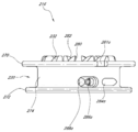
앞에서 언급된 것과 같이, 손잡이 부재(218)는 구속된 위치와 구속이 해제된 위치 사이에서 축 방향으로 이동이 가능할 수 있다. 도 23A는 손잡이 부재(218)가 구속된 구성의 릴(204)의 전개 사시도이다. 도 23B는 손잡이 부재(218)가 구속된 구성의 릴(204)의 단면도이다. 도 24A는 손잡이 부재(218)가 구속 해제된 구성의 릴(204)의 전개도 이다. 도 24B는 손잡이 부재(218)가 구속 해제된 구성의 릴(204)의 단면도이다. 손잡이 부재(218)는 파스너(300)를 돌려서 베이스 부재(214)에 단단히 고정될 수 있고 나사산(358)이 축(244)에 형성된 보어(246)의 대응하는 나사산과 체결되도록 한다. 몇몇 실시예에 있어서, 파스너(300)가 충분히 조여졌을 때, 스풀 (216)을 통과하여 위로 연장되는 축(244)의 부분은 스프링 부싱(298)을 관통하여 형성된 중앙 개구(348)의 하부 부분 안으로 들어갈 수 있다. 스프링 부싱(298)의 바닥 가장자리(398)는 스풀 치들(232)의 내측 환형부(400)와 접촉하거나, 거의 접촉할 수 있다.As previously mentioned, the
손잡이 부재(218)가 구속된 위치에 있을 때, 도 23A 및 도 23B에 도시된 것과 같이, 스프링 부싱(298) 및 파스너(300)는 손잡이 스프링(302)에 의해서 올려진 위치에서 유지될 수 있고, 앞에서 언급된 것과 같이, 스프링 부싱(298)의 바닥 가장자리(398)는 손잡이 코어(296)의 중앙 개구(316)를 통과하여 연장되지 않게 된다. 그러므로, 손잡이 코어(296)의 바닥이 스풀(216)의 상부 표면과 접촉하거나 근접된 상태에서, 손잡이 부재(218)는 하부 구속 위치에 유지된다(도 5에서 점선으로 도시됨). 그러므로, 구속된 위치에 있을 때, 손잡이 치들(234)은 스풀 치들(232)과 맞물리고, 폴들(236)은 하우징 치들(224)과 맞물린다.When the
손잡이 부재(218)가 구속 해제된 위치에 있을 때, 도 24A 및 도 24B에 도시된 것과 같이, 스프링 부싱(298) 및 파스너(300)는 손잡이 스프링(302)에 의해서 낮아진 위치에서 유지될 수 있고, 앞에서 설명된 것과 같이, 스프링 부싱(298)의 바닥 가장자리(398)는 손잡이 코어(296)의 중앙 개구(316)를 통과하여 대략 1.0 mm 및/또는 3.0 mm 이하 정도, 몇몇 실시예에 있어서 2.25 mm 정도 연장되도록 하나, 이러한 범위 밖의 다른 구성들도 또한 가능하다. 스프링 부싱(298)의 바닥 가장자리(398)는 스풀(216)의 환형부(400)와 계속 접촉하거나, 거의 접촉하게 되고, 손잡이 부재(218)는 스풀(216) 및 베이스 부재(214)로부터 떨어지도록 손잡이 치들(234)이 스풀 치들(232)로부터 구속이 해제되도록 하고 및/또는 폴들(236)이 하우징 치들(224)로부터 구속이 해제되도록 하기에 충분한 일정 양 만큼(예를 들면, 대략 2.25 mm) 올려 진다. 도시된 실시예에 있어서, 손잡이가 구속이 해제된 위치에 있을 때, 손잡이 치들(234)은 스풀 치들(232)로부터 맞물림이 해제되고 폴들(236)도 또한 하우징 치들(224)로부터 맞물림이 해제된다. 그러므로, 도시된 구속이 해제된 구성에서 끈 조임 시스템(200)을 풀기 위하여 손잡이 부재(218)와 독립적으로 스풀(216)은 푸는 방향으로 회전이 자유롭게 될 수 있고, 손잡이 부재(218)는 조이거나 푸는 방향 양쪽으로 회전이 자유롭게 될 수 있다.When the
많은 변형 예들이 가능하다. 몇몇 실시예에 있어서, 구속이 해제된 위치에 있을 때, 폴들(236)이 하우징 치들(224)과 계속 맞물려 있는 동안에(예를 들어, 도 17에 도시된 계단(340)이 폴 치들(338a-b)이 아래로 더 연장되도록 크게 만들어 졌다면) 손잡이 치들(234)은 스풀 치들(232)로부터 맞물림이 해제될 수 있다. 이러한 실시예들에서, 손잡이 부재(218)는 구속이 해제된 위치에서도 풀리는 방향으로 회전이 방지될 수 있으나, 스풀(216)은 끈 조임 시스템(200)을 풀기 위하여 끈이 인출되는 것을 허용하도록 손잡이 부재(218)와 독립적으로 풀리는 방향으로 회전하는 것이 자유롭게 될 수 있다. 몇몇 실시예에 있어서, 구속이 해제된 위치에서, 폴들(236)이 하우징 치들(224)로부터 맞물림이 해제될 수 있으나 손잡이 치들(234)은 스풀 치들(232)과 계속 맞물릴 수 있다(예를 들면, 손잡이 치들(234) 및/또는 스풀 치들(232)이 도시된 실시예들에서 보다 길게 만들어진 경우). 이러한 실시예들에 있어서, 구속이 해제된 위치에 있을 때도 스풀(216)은 손잡이 부재(218)와 계속 결합되어 있으나, 끈 조임 시스템(200)을 풀기 위하여 끈(206)을 릴(204)로부터 풀어내기 위하여 손잡이 부재(218) 및 스풀(216)은 함께 풀리는 방향으로 회전하는 것이 허용된다. 다른 변형 예들이 가능하다. 예를 들면, 몇몇 실시예에 있어서, 스풀(216)은 손잡이 부재(218)와 일체로 형성될 수 있고, 또는 고정가능하게 부착되거나, 또는 제거 가능하게 부착될 수 있고, 스풀 치들(232) 및 손잡이 치들(234)은 생략될 수 있다.Many variations are possible. In some embodiments, when the restraint is in the disengaged position, while the
앞에서 언급된 것과 같이, 구속이 해제된 위치에 있을 때, 폴들(236)은 하우징 치들(224)로부터 구속이 해제되기에 충분할 정도로 올려질 수 있다. 몇몇 실시예에 있어서, 폴들이 폴 스프링(232)에 의해서 반경 방향 외측으로 편향되기 때문에, 폴들(236)은 반경 방향 외측으로 휠 수 있어서 폴들(236)의 바닥 면들의 부분들이 하우징 치들(224)의 상부 면들의 부분들 위에 위치되도록 한다. 그러므로 몇몇 실시예에 있어서, 손잡이 부재(218)가 구속된 위치까지 후방으로 이동되었을 때, 폴들(236)은 하우징 치들(224)과 다시 맞물릴 수 있도록 반경 방향 내측으로 휘어져야 한다. 또한 앞에서 설명된 것과 같이, 하우징 치들(224)의 상부 표면들(266)의 적어도 일부분은 각이 지거나 경사질 수 있고 및/또는 폴들(236)의 바닥 표면들(339)의 적어도 일부분은 각이 지거나 경사질 수 있고, 손잡이 부재가 구속된 위치로 되돌려 질 때 가해지는 아래 방향 압력은 폴들(236)이 하우징 치들(224)과 다시 맞물리는 것을 용이하게 하기 위하여 폴들(236)이 반경 방향 내측으로 휘게 할 수 있다. 몇몇 실시예에 있어서, 폴 함몰부들(324) 또는 손잡이 부재(218)의 다른 부분들은 폴들(236)이 하우징 치들(224)과 맞물리는 반경 위치를 통과하여 폴들(236)이 반경 방향 외측으로 휘는 것을 방지하도록 구성될 수 있고, 그것에 의해서 손잡이 부재(218)를 구속된 위치로 이동시킬 때 폴들(236)을 내측으로 휘게 하는 필요를 줄이거나 제거하게 된다.As previously mentioned, when in the restrained position, the
스프링 부싱(298)이 손잡이 스프링(302)을 옮기고 거기를 통과하도록 하기에 충분한 힘으로 손잡이 부재(218)를 베이스 부재(214)로부터 떨어지도록 축선 방향으로 당겨서 손잡이부재(218)를 구속된 위치로부터 구속이 해제된 위치로 이동시킬 수 있다. 손잡이 부재(218)를 구속이 해제된 위치로부터 구속된 위치로 이동시키기 위하여 스프링 부싱(298)이 손잡이 스프링(302)을 옮기고 거기를 통과하도록 하기에 충분한 힘으로 손잡이 부재(218)는 베이스 부재(214)를 향하여 축선 방향으로 눌려질 수 있다.The
폴들(236)이 하우징 치들(224)과 반경 방향으로 맞물리는 것은 손잡이 부재(218)를 푸는 방향으로 돌리려하는 힘을 가해져서 손잡이 부재(218)를 구속된 위치로부터 구속이 해제된 위치로 우연적으로 이동시키는 것을 줄이거나 제거할 수 있다. 만약 끈(206)이 당겨지면, 스풀(216)을 푸는 방향으로 회전시키려는 힘을 주게 되고, 그 힘은 스풀 치들(232) 및 손잡이 치들(234)을 경유하여 손잡이(218)로 전달될 수 있고, 폴들(236)은 정해진 수의 하우징 치들(224) 사이에 반경 방향으로 그 힘을 분배할 수 있다. 폴들(236)은 하우징 치들과, 축선 방향이 아니라, 반경 방향에서 맞물리기 때문에, 그리고 폴들(236)은 (릴(204)을 조일 때) 반경 방향으로 옮겨지도록 구성되어 있기 때문에, 실질적으로 어떠한 힘도 손잡이(218)에 축선 방향으로 작용되지 않는다. 그러므로, 반경 방향 폴들(236)은 우연적인 손잡이 부재의 구속해제 및/또는 우연적인 스풀의 풀림을 초래할 수 있는 축선 방향으로 어떠한 실질적인 힘을 부여하지 않는다. 그러므로, 릴(204)은 폴들이 하우징 치들과 축선 방향으로 맞물리고 조이는 동안 폴들이 축선 방향으로 이동하도록 구성된 릴보다 끈(206)을 당기려고 작용되거나 우연적으로 손잡이 부재(218)를 해제하려고 하지 않고 손잡이 부재(218)를 푸는 방향으로 회전시키려고 작용되는 더 큰 힘을 버티도록 구성될 수 있다.The radial engagement of the
또한, 몇몇 실시예에 있어서, 손잡이(218)가 푸는 방향으로 돌려졌을 때 폴들(236)에게 작용되는 힘은 폴 빔들(330)에 의해서 견디어 지므로 어떠한 힘도 실질적으로 폴 스프링(332)에게 전달되지 않는다. 그러므로, 폴 스프링들(332)은 아주 유연하도록 구성될 수 있고 반면에 폴 빔들(330)은 실질적으로 휘어지지 않을 정도로 단단하게 구성될 수 있다. 그러므로, 단단한 폴 빔들(330)에 의해서 힘이 버텨지기 때문에 폴들(236)은 풀리는 방향으로 손잡이 부재(218)에 작용되는 비교적 큰 힘에 저항하도록 구성될 수 있으며, 반면에 힘이 유연한 폴 스프링들(332)에게 전달되기 때문에 또한 손잡이 부재(218)를 회전시키기 위하여 비교적 작은 힘이 조이는 방향으로 작용될 때 폴들은 반경 방향으로 회전하도록 구성될 수 있다.Also, in some embodiments, the force acting on the
여기서 설명된 끈 조임 시스템의 부품들은 플라스틱, 탄소 또는 다른 섬유 강화 플라스틱, 알루미늄, 강철, 고무 같은 적당한 재료, 또는 다른 적당한 재료 또는 그러한 재료들의 조합으로 형성될 수 있다. 몇몇 실시예에 있어서, 베이스 부재(214), 스풀(216), 손잡이 코어(296), 폴들(236), 스프링 부싱(298), 손잡이 커버(304), 끈 가이드들, 또는 여기서 설명된 다른 적당한 부품들은 사출되거나 아니면 나일론, PVC 또는 PET 와 같은 적당한 고분자 재료로 형성될 수 있다. 여기서 설명된 부품들 중 몇몇은 PTFE와 같은 매끈한 플라스틱, 또는 끈과 그러한 부품들 사이의 마찰을 원하는 정도 줄이는 데 사용할 수 있는 재료로 형성될 수 있다. 부가적으로, 여기서 설명된 부품들 중 몇몇은 상호 작용하는 부품들 또는 부분들과의 마찰을 줄이기 위하여 매끄러운 재료로 코팅되거나 적층될 수 있다. 패스너(300) 및 손잡이 스프링(302)은 금속(예를 들면, 알루미늄 또는 강철)으로 만들어 질 수 있으나, 플라스틱과 같은 다른 재료들도 또한 사용될 수 있다. 손잡이 그립(306)은 고무, 또는 라텍스, 또는 실리콘, 또는 손잡이 부재(218)의 쥠을 용이하게 할 수 있는 임의의 다른 재료로 형성될 수 있다.The parts of the string tightening system described herein may be formed of a suitable material such as plastic, carbon or other fiber reinforced plastic, aluminum, steel, rubber, or other suitable material or combinations of such materials. In some embodiments,
도 25는 앞에서 설명된 베이스 부재(214) 대신에 사용될 수 있는 베이스 부재(414)의 다른 실시예의 사시도이다. 베이스 부재(414)는 하우징(420) 및 장착 플랜지(422)를 포함할 수 있고, 예를 들면 도 2에 도시된 것과 같이 끈을 베이스 부재(214)로부터 멀어지도록 축방향으로 방향을 돌리는 대신에 끈을 베이스 부재(414)로부터 멀어지도록 대체로 반경 방향으로 방향을 돌리도록 구멍들(426a-b)이 구성된 것을 제외하고, 앞에서 설명된 베이스 부재(214)와 대체로 유사할 수 있다. 또한, 끈 구멍들(426a-b)은 앞에서 설명된 베이스 부재(214)에서와 같이 대향하는 단부들에 배치되기 보다는 베이스 부재(414)의 대체로 동일한 측부에 배치될 수 있다. 끈 조임 시스템이 적용되는 특별한 적용 예들에 의존하는 많은 변형 예들이 가능하다. 예를 들면, 몇몇 실시예에 있어서, 베이스 부재는 단지 하나의 끈 구멍을 포함할 수 있고 끈의 단지 일 단부만 하우징으로 들어가서 스풀에 부착될 수 있다. 이러한 실시예들에 있어서, 끈의 다른 쪽 단부는 베이스 부재 또는 조여지는 물품에 부착될 수 있다.25 is a perspective view of another embodiment of a
도 26은 여기에서 설명된 릴(204)과 여러 가지 면에서 유사한 릴에서 사용될 수 있는 손잡이 코어(596)의 다른 실시예의 단면도이다. 손잡이 코어(596)는 릴의 제조와 조립을 단순화하기 위하여 손잡이 코어(596)와 일체로 형성될 수 있는 폴들(536)을 포함할 수 있다. 다른 실시예에 있어서, 폴들(539)은 손잡이 코어(596)에 적당한 방식으로 접착될 수 있다. 폴들(536)은 앞에서 설명된 것과 유사한 방식으로 손잡이 코어(596)가 조이는 방향(화살표 A로 도시됨)으로 회전될 때 폴들(536)이 하우징 치들에 의해서 반경 방향 내측으로 옮겨지는 것을 허용할 정도의 유연한 재료, 두께, 및 길이로 만들어 질 수 있다. 폴들(536)은 폴 아암들(532)의 단부들에 형성된 폴 치들(538a-b)을 포함할 수 있다. 도시된 실시예에 있어서 폴(536) 마다 두 개의 폴치들(538a-b)이 사용되었으나, 임의의 적당한 수의 폴 치들(538a-b)이 사용될 수 있다. 도 26에 도시된 바와 같이, 폴들(536)은 폴 아암(532)을 포함하며, 폴들(536)의 폴 아암(532)은 손잡이 코어(596)에 고정적으로 연결된 근접 단부(proximal end)와 폴 치들(538a-b)를 포함하는 말단부(distal end)를 갖는다.26 is a cross-sectional view of another embodiment of a
손잡이 코어(596)가 푸는 방향으로 돌려졌을 때(화살표 B로 도시됨), 폴 치들(538a-b)은 손잡이 코어(596)가 푸는 방향으로 회전하는 것을 방지하기 위하여 하우징 치들(도 26에 미 도시됨)을 누르도록 걸릴 수 있다. 도 26에 도시된 힘 화살표들은 힘이 반경 방향으로 분배되는 방향을 도시한다. 폴 치들(538a-b)이 하우징 치들에 걸릴 때, 도시된 것과 같이 폴 치들(538a-b)로부터 작용된 힘이 하우징 치들에게로 작용된다. 폴 아암들(532)은 도시된 것과 같이 곡선으로 될 수 있고, 폴 치들(538a-b)이 하우징 치들에 걸릴 때, 폴 아암들(532)이 도 26에 화살표로 도시된 것과 같이 반경 방향 외측으로 휘거나 굽혀지게 된다. 폴들(536)은 하우징 치들이 폴 아암들(532)에 접촉하도록 구성될 수 있고, 폴 아암들(532)이 반경 방향 외측으로 휘거나 굽혀지려고 할 때, 그들이 하우징 치들의 정상에 걸리도록 하여, 하우징 치들에 반경 방향으로 힘을 분배하고, 굽혀지는 것이 방지되도록 한다. 몇몇 실시예에 있어서, 하우징 치들은 실질적으로 폴 아암들(532)이 반경 방향 외측으로 이동하는 것을 방지할 수 있다. 조이는 동안에 폴들(536)이 하우징 치들과 축선 방향이 아니라 반경 방향으로 맞물리기 때문에, 그리고 폴들(536)이 축선 방향이 아니라 반경 방향으로 옮겨지도록 구성되어 있기 때문에, 풀리는 방향으로 회전할 때 작용되는 어떠한 힘도 실질적으로 축선 방향으로 작용되지 않고 그것에 의해서 구속된 위치로부터 구속이 해제된 위치로의 손잡이 코어(596)의 우연적인 축선 방향 이동의 발생을 줄이거나 제거하게 된다.When the
비록 여기에서 끈 조임 시스템의 다양한 실시예들이 설명되었으나, 다양한 부품들, 특징들, 또는 여기서 설명된 끈 조임 시스템의 다른 측면들은 여기에서 명시적으로 설명되지 않은 추가적인 끈 조임 시스템의 실시예들을 형성하기 위하여 결합되거나 교체될 수 있고, 이 모든 것은 본 개시의 부분으로 고려될 수 있다. 추가로, 많은 변형예들이 도시되고 상세히 설명되었으나, 본 발명의 범위에 속하는 다른 변형예들은 본 개시에 기초하여 본 발명의 분야에 있는 통상의 기술자에게 자명한 것이 될 것이다. 그러므로 본 발명의 개시의 범위는 위에서 기술된 특정한 개시 실시예들에 한정되지 않는다.Although various embodiments of a string fastening system have been described herein, various parts, features, or other aspects of the string fastening system described herein form embodiments of additional string fastening systems not explicitly described herein. Can be combined or replaced, all of which can be considered as part of the present disclosure. Additionally, although many variations have been shown and described in detail, other variations that fall within the scope of the present invention will become apparent to those skilled in the art based on the present disclosure. Therefore, the scope of the present disclosure is not limited to the specific disclosed embodiments described above.
Claims (1)
복수의 치들을 포함하는 하우징과,
상기 하우징에 의해서 지지되고, 상기 하우징에 대하여 회전 가능한 스풀로서, 상기 스풀은 그 안에 형성된 채널을 포함하고, 상기 채널은 상기 스풀이 조이는 방향으로 회전될 때 상기 끈 조임 시스템을 조이도록 끈을 모으고 상기 스풀이 풀리는 방향으로 회전될 때 끈 조임 시스템을 풀도록 끈을 방출하게 구성된 스풀과,
상기 하우징에 의해서 지지되는 손잡이로서, 상기 손잡이는 회전축을 중심으로 상기 하우징에 대하여 회전 가능하고, 상기 손잡이의 회전이 상기 스풀도 회전하게 하도록 상기 스풀에 결합된 손잡이와,
손잡이 코어로서, 손잡이 코어와 일체로 형성된 하나 이상의 폴들을 포함하고, 상기 하나 이상의 폴들은 상기 손잡이 코어에 고정적으로 연결된 근접 단부(proximal end)와 폴 치를 포함하는 말단부(distal end)를 갖는 폴 아암을 구비하는 손잡이 코어를 포함하고,
상기 손잡이 코어가 풀리는 방향으로 회전할 때 상기 손잡이 코어와 스풀이 풀리는 방향으로 회전하는 것을 방지하도록, 상기 폴 치는 상기 복수의 치들과 맞물리도록 구성되며, 상기 손잡이가 조이는 방향으로 돌려질 때, 상기 손잡이 코어와 스풀이 조이는 방향으로 회전할 수 있도록, 상기 폴 치가 상기 복수의 치들로부터 반경 방향 안쪽으로 이동하며,
상기 손잡이 코어는 맞물림 위치와 맞물림 해제 위치 사이에서 이동 가능하며,
상기 손잡이 코어가 맞물림 위치에 있을 때, 상기 스풀은 풀리는 방향으로 회전하는 것이 방지되며, 상기 손잡이 코어가 맞물림 해제 위치에 있을 때 상기 스풀은 풀리는 방향으로 회전할 수 있는 끈 조임 시스템에서 사용되기 위한 릴.A reel for use in a string tightening system, the reel comprising:
A housing including a plurality of teeth,
As a spool supported by the housing and rotatable relative to the housing, the spool includes a channel formed therein, the channel collecting the string to tighten the string tightening system when the spool is rotated in the tightening direction and the A spool configured to release the string to loosen the string tightening system when the spool is rotated in the unwinding direction
As a handle supported by the housing, the handle is rotatable relative to the housing about an axis of rotation, and a handle coupled to the spool so that rotation of the handle causes the spool to rotate,
A handle core comprising one or more poles integrally formed with the handle core, the one or more poles comprising a pole arm having a proximal end fixedly connected to the handle core and a distal end comprising a pole tooth. It includes a handle core provided,
To prevent the handle core and the spool from rotating when the handle core is rotated in the unwinding direction, the pawl is configured to engage the plurality of teeth, and when the handle is rotated in the tightening direction, the handle The pole teeth move radially inward from the plurality of teeth so that the core and the spool can rotate in the tightening direction,
The handle core is movable between the engaged position and the disengaged position,
When the handle core is in the engaged position, the spool is prevented from rotating in the disengaging direction, and when the handle core is in the disengaged position, the spool is reel for use in a string tightening system that can rotate in the unlocking direction .
Priority Applications (1)
| Application Number | Priority Date | Filing Date | Title |
|---|---|---|---|
| KR1020207022830A KR102269934B1 (en) | 2010-04-30 | 2011-04-29 | Reel based lacing system |
Applications Claiming Priority (3)
| Application Number | Priority Date | Filing Date | Title |
|---|---|---|---|
| US33012910P | 2010-04-30 | 2010-04-30 | |
| US61/330,129 | 2010-04-30 | ||
| PCT/US2011/034692 WO2011137405A2 (en) | 2010-04-30 | 2011-04-29 | Reel based lacing system |
Related Parent Applications (1)
| Application Number | Title | Priority Date | Filing Date |
|---|---|---|---|
| KR1020197001675A Division KR102128867B1 (en) | 2010-04-30 | 2011-04-29 | Reel based lacing system |
Related Child Applications (1)
| Application Number | Title | Priority Date | Filing Date |
|---|---|---|---|
| KR1020207022830A Division KR102269934B1 (en) | 2010-04-30 | 2011-04-29 | Reel based lacing system |
Publications (1)
| Publication Number | Publication Date |
|---|---|
| KR20200077624A true KR20200077624A (en) | 2020-06-30 |
Family
ID=44857505
Family Applications (8)
| Application Number | Title | Priority Date | Filing Date |
|---|---|---|---|
| KR1020207018257A KR20200077624A (en) | 2010-04-30 | 2011-04-29 | Reel based lacing system |
| KR1020197001675A KR102128867B1 (en) | 2010-04-30 | 2011-04-29 | Reel based lacing system |
| KR1020207022830A KR102269934B1 (en) | 2010-04-30 | 2011-04-29 | Reel based lacing system |
| KR1020217030527A KR102428664B1 (en) | 2010-04-30 | 2011-04-29 | Reel based lacing system |
| KR1020187018779A KR101942227B1 (en) | 2010-04-30 | 2011-04-29 | Reel based lacing system |
| KR1020127031319A KR101875508B1 (en) | 2010-04-30 | 2011-04-29 | Reel based lacing system |
| KR1020217019143A KR20210079413A (en) | 2010-04-30 | 2011-04-29 | Reel based lacing system |
| KR1020227026401A KR102566159B1 (en) | 2010-04-30 | 2011-04-29 | Reel based lacing system |
Family Applications After (7)
| Application Number | Title | Priority Date | Filing Date |
|---|---|---|---|
| KR1020197001675A KR102128867B1 (en) | 2010-04-30 | 2011-04-29 | Reel based lacing system |
| KR1020207022830A KR102269934B1 (en) | 2010-04-30 | 2011-04-29 | Reel based lacing system |
| KR1020217030527A KR102428664B1 (en) | 2010-04-30 | 2011-04-29 | Reel based lacing system |
| KR1020187018779A KR101942227B1 (en) | 2010-04-30 | 2011-04-29 | Reel based lacing system |
| KR1020127031319A KR101875508B1 (en) | 2010-04-30 | 2011-04-29 | Reel based lacing system |
| KR1020217019143A KR20210079413A (en) | 2010-04-30 | 2011-04-29 | Reel based lacing system |
| KR1020227026401A KR102566159B1 (en) | 2010-04-30 | 2011-04-29 | Reel based lacing system |
Country Status (6)
| Country | Link |
|---|---|
| US (2) | US8516662B2 (en) |
| JP (8) | JP5925765B2 (en) |
| KR (8) | KR20200077624A (en) |
| CN (1) | CN103153112B (en) |
| DE (2) | DE112011106171B3 (en) |
| WO (1) | WO2011137405A2 (en) |
Families Citing this family (236)
| Publication number | Priority date | Publication date | Assignee | Title |
|---|---|---|---|---|
| US20060156517A1 (en) | 1997-08-22 | 2006-07-20 | Hammerslag Gary R | Reel based closure system |
| EP1814417B1 (en) | 2004-10-29 | 2014-04-16 | Boa Technology, Inc. | Reel based closure system |
| KR101553243B1 (en) | 2006-09-12 | 2015-09-15 | 보아 테크놀러지, 인크. | Closure system for braces, protective wear and similar articles |
| KR20100129278A (en) | 2008-01-18 | 2010-12-08 | 보아 테크놀러지, 인크. | Closure system |
| US8046937B2 (en) | 2008-05-02 | 2011-11-01 | Nike, Inc. | Automatic lacing system |
| US11723436B2 (en) | 2008-05-02 | 2023-08-15 | Nike, Inc. | Article of footwear and charging system |
| US11206891B2 (en) | 2008-05-02 | 2021-12-28 | Nike, Inc. | Article of footwear and a method of assembly of the article of footwear |
| CN102026594B (en) | 2008-05-15 | 2013-12-25 | 欧苏尔公司 | Orthopedic devices utilizing rotary tensioning |
| WO2010059989A2 (en) | 2008-11-21 | 2010-05-27 | Boa Technology, Inc. | Reel based lacing system |
| EP2400936B1 (en) | 2009-02-26 | 2015-09-09 | Össur HF | Orthopedic device for treatment of the back |
| US9293667B2 (en) | 2010-08-19 | 2016-03-22 | Soraa, Inc. | System and method for selected pump LEDs with multiple phosphors |
| US8657769B2 (en) | 2009-11-04 | 2014-02-25 | Ossur Hf | Thoracic lumbar sacral orthosis |
| US8713820B2 (en) | 2010-01-21 | 2014-05-06 | Boa Technology, Inc. | Guides for lacing systems |
| US9375053B2 (en) | 2012-03-15 | 2016-06-28 | Boa Technology, Inc. | Tightening mechanisms and applications including the same |
| US10070695B2 (en) | 2010-04-30 | 2018-09-11 | Boa Technology Inc. | Tightening mechanisms and applications including the same |
| JP5925765B2 (en) | 2010-04-30 | 2016-05-25 | ボア テクノロジー,インコーポレイテッド | Reel for use in a lacing system, method of making the reel, and pawl used with the reel |
| CN103079418B (en) | 2010-07-01 | 2015-11-25 | 博技术有限公司 | Lace guide |
| CA2804759C (en) | 2010-07-01 | 2019-06-18 | Boa Technology, Inc. | Braces using lacing systems |
| EP2672937B1 (en) | 2011-02-10 | 2017-04-19 | Össur HF | Tightening system for an orthopedic article |
| KR101107372B1 (en) * | 2011-05-30 | 2012-01-19 | 소윤서 | Apparatus for adjusting length of lace |
| WO2012177700A2 (en) | 2011-06-20 | 2012-12-27 | Ossur Hf | Orthopedic device, use of orthopedic device and method for producing the same |
| US8434200B2 (en) * | 2011-07-13 | 2013-05-07 | Chin-Chu Chen | Adjusting device for tightening or loosing laces and straps |
| KR101099458B1 (en) * | 2011-07-25 | 2011-12-27 | 주식회사 신경 | Apparatus for fastening shoe strip |
| US8904673B2 (en) * | 2011-08-18 | 2014-12-09 | Palidium, Inc. | Automated tightening shoe |
| US8904672B1 (en) * | 2011-08-18 | 2014-12-09 | Palidium Inc. | Automated tightening shoe |
| US9101181B2 (en) * | 2011-10-13 | 2015-08-11 | Boa Technology Inc. | Reel-based lacing system |
| US20130161365A1 (en) * | 2011-12-22 | 2013-06-27 | Nuvo Enterprise Co., Ltd. | Adjustable structure of bicycle water bottle rack |
| WO2013106666A1 (en) | 2012-01-13 | 2013-07-18 | Ossur Hf | Spinal orthosis and method for using the same |
| US9572705B2 (en) | 2012-01-13 | 2017-02-21 | Ossur Hf | Spinal orthosis |
| US11071344B2 (en) | 2012-02-22 | 2021-07-27 | Nike, Inc. | Motorized shoe with gesture control |
| US11684111B2 (en) | 2012-02-22 | 2023-06-27 | Nike, Inc. | Motorized shoe with gesture control |
| US9144168B2 (en) | 2012-03-08 | 2015-09-22 | The United States Of America, As Represented By The Secretary Of The Air Force | Appendage-mounted display apparatus |
| US9179729B2 (en) | 2012-03-13 | 2015-11-10 | Boa Technology, Inc. | Tightening systems |
| US8919293B2 (en) * | 2012-03-20 | 2014-12-30 | In The Lead, Llc | Self-containing, retractable leash and collar/harness assembly |
| US9226531B2 (en) | 2012-05-31 | 2016-01-05 | Under Armour, Inc. | Sportman's garment |
| DE102012011742A1 (en) * | 2012-06-08 | 2013-12-12 | Bauerfeind Ag | Clamping device for orthoses |
| WO2014001918A2 (en) * | 2012-06-22 | 2014-01-03 | Revision Military S.A.R.L. | Tensioning reel |
| US9237778B2 (en) * | 2012-06-25 | 2016-01-19 | Specialized Bicycle Components, Inc. | Cycling shoe |
| US9241539B1 (en) * | 2012-06-29 | 2016-01-26 | Jeffrey Keswin | Shoelace tightening method and apparatus |
| US10206451B2 (en) | 2012-07-06 | 2019-02-19 | Specialized Bicycle Components, Inc. | Cycling shoe |
| EP2890265A1 (en) * | 2012-08-30 | 2015-07-08 | Roland Iten Mechanical Luxury SA | Calibration system for adjusting straps, such as watch straps or such as belts with locking mechanism |
| CN104582519B (en) | 2012-08-31 | 2016-08-24 | 耐克创新有限合伙公司 | Motor-driven clamping system |
| EP3804552B1 (en) | 2012-08-31 | 2023-10-11 | Nike Innovate C.V. | Footwear tension control system |
| US10918561B2 (en) * | 2012-09-14 | 2021-02-16 | Recovery Force, LLC | Compression device |
| US10441491B2 (en) * | 2012-09-14 | 2019-10-15 | Recovery Force, LLC | Compression device |
| US10688007B2 (en) | 2012-09-14 | 2020-06-23 | Recovery Force, LLC | Compression device |
| CN104853699B (en) | 2012-09-19 | 2017-08-15 | 欧苏尔公司 | Panel attachment for orthopedic appliance adjusts system with girth |
| WO2014071319A1 (en) | 2012-11-02 | 2014-05-08 | Boa Technology Inc. | Coupling members for closure devices and systems |
| EP2916680B1 (en) | 2012-11-06 | 2018-12-26 | Boa Technology Inc. | Devices and methods for adjusting the fit of footwear |
| HUE033756T2 (en) * | 2012-11-30 | 2017-12-28 | Puma SE | Rotary closure for a shoe |
| US9351539B2 (en) | 2012-12-11 | 2016-05-31 | Bell Sports, Inc. | Controlled release buckle |
| KR101249420B1 (en) * | 2012-12-17 | 2013-04-03 | 주식회사 신경 | Apparatus for fastening wire |
| JP5649669B2 (en) * | 2013-01-11 | 2015-01-07 | 株式会社シマノ | Tightening string and shoes using it |
| US9554935B2 (en) | 2013-01-24 | 2017-01-31 | Ossur Hf | Orthopedic device for treating complications of the hip |
| US9795500B2 (en) | 2013-01-24 | 2017-10-24 | Ossur Hf | Orthopedic device for treating complications of the hip |
| US10357391B2 (en) | 2013-01-24 | 2019-07-23 | Ossur Hf | Orthopedic device for treating complications of the hip |
| EP2948107B1 (en) | 2013-01-24 | 2018-07-11 | Össur HF | Orthopedic device for treating complications of the hip |
| EP2948014B1 (en) | 2013-01-28 | 2019-06-26 | Boa Technology Inc. | Lace fixation assembly and system |
| US9153215B2 (en) | 2013-01-31 | 2015-10-06 | Final Frontier Technology, Llc | Mouthpiece ligature for woodwind instruments |
| US10702409B2 (en) | 2013-02-05 | 2020-07-07 | Boa Technology Inc. | Closure devices for medical devices and methods |
| US10251451B2 (en) | 2013-03-05 | 2019-04-09 | Boa Technology Inc. | Closure devices including incremental release mechanisms and methods therefor |
| EP2964048B1 (en) | 2013-03-05 | 2019-08-28 | Boa Technology Inc. | Systems and devices for automatic closure of medical devices |
| US9706814B2 (en) | 2013-07-10 | 2017-07-18 | Boa Technology Inc. | Closure devices including incremental release mechanisms and methods therefor |
| US9357807B2 (en) | 2013-03-15 | 2016-06-07 | Under Armour, Inc. | Size adjustment arrangement for a garment |
| US9285776B1 (en) * | 2013-03-15 | 2016-03-15 | Vortic, Llc | Band tightening system |
| KR20230155599A (en) | 2013-04-01 | 2023-11-10 | 보아 테크놀러지, 인크. | Methods and devices for retrofitting footwear to include a reel based closure system |
| ITTV20130045A1 (en) * | 2013-04-09 | 2014-10-10 | Northwave Srl | TIGHTENING DEVICE |
| US10076160B2 (en) * | 2013-06-05 | 2018-09-18 | Boa Technology Inc. | Integrated closure device components and methods |
| WO2014197721A2 (en) * | 2013-06-05 | 2014-12-11 | Boa Technology Inc. | Integrated closure device components and methods |
| US9474330B2 (en) | 2013-06-10 | 2016-10-25 | Nike, Inc. | Article with adjustable rearward covering portion |
| JP6105404B2 (en) * | 2013-06-18 | 2017-03-29 | 株式会社ジャパーナ | Shoelace winding reel |
| JP6087219B2 (en) * | 2013-06-18 | 2017-03-01 | 株式会社ジャパーナ | Shoelace winding device |
| US10863794B2 (en) | 2013-06-25 | 2020-12-15 | Nike, Inc. | Article of footwear having multiple braided structures |
| CN105246362B (en) | 2013-06-25 | 2018-04-06 | 耐克创新有限合伙公司 | Article of footwear with braiding vamp |
| US9629417B2 (en) * | 2013-07-02 | 2017-04-25 | Boa Technology Inc. | Tension limiting mechanisms for closure devices and methods therefor |
| EP3593766A3 (en) * | 2013-07-30 | 2020-09-23 | United Surgical Associates, Inc. | Orthopedic brace securing and tensioning system |
| EP2832315B1 (en) * | 2013-07-31 | 2017-11-22 | Venus MedTech (HangZhou), Inc. | Handle assembly for implant delivery apparatus comprising a brake frame assembly, a force limiter and/or a displacement limiter |
| KR101506676B1 (en) * | 2013-09-03 | 2015-03-30 | 주식회사 신경 | apparatus for fastening wire and method for mounting thereof |
| WO2015035257A2 (en) | 2013-09-05 | 2015-03-12 | Boa Technology Inc. | Alternative lacing guides for tightening mechanisms and methods therefor |
| WO2015039052A2 (en) * | 2013-09-13 | 2015-03-19 | Boa Technology Inc. | Failure compensating lace tension devices and methods |
| CN105722419B (en) | 2013-09-20 | 2018-06-05 | 耐克创新有限合伙公司 | Footwear with removable motor-driven regulating system |
| JP2015070802A (en) * | 2013-10-02 | 2015-04-16 | 株式会社シマノ | Fishing bag |
| AU2014336949A1 (en) * | 2013-10-14 | 2016-06-09 | Falekava F. Mahe | Portable and detachable lace storage device |
| KR101895140B1 (en) | 2013-11-18 | 2018-09-04 | 보아 테크놀러지, 인크. | Methods and devices for providing automatic closure of prosthetics and orthotics |
| USD835976S1 (en) | 2014-01-16 | 2018-12-18 | Boa Technology Inc. | Coupling member |
| TWI561453B (en) * | 2014-02-17 | 2016-12-11 | Chin Chu Chen | A device for tightening and loosening a lace |
| US9364054B2 (en) * | 2014-04-09 | 2016-06-14 | Tristan S. Gittens | Accessory cinching device |
| US9326566B2 (en) | 2014-04-15 | 2016-05-03 | Nike, Inc. | Footwear having coverable motorized adjustment system |
| US10092065B2 (en) | 2014-04-15 | 2018-10-09 | Nike, Inc. | Footwear having motorized adjustment system and removable midsole |
| US9629418B2 (en) | 2014-04-15 | 2017-04-25 | Nike, Inc. | Footwear having motorized adjustment system and elastic upper |
| KR101438572B1 (en) | 2014-04-24 | 2014-09-12 | 주식회사 신경 | apparatus for fastening wire |
| US9763808B2 (en) * | 2014-05-19 | 2017-09-19 | Ossur Hf | Adjustable prosthetic device |
| US10512305B2 (en) | 2014-07-11 | 2019-12-24 | Ossur Hf | Tightening system with a tension control mechanism |
| US9713357B2 (en) | 2014-07-15 | 2017-07-25 | Taylor Made Golf Company, Inc. | Asymmetric shoes |
| CN203952623U (en) * | 2014-07-18 | 2014-11-26 | 陈祈勋 | Bring system together and tie up device |
| KR101584194B1 (en) * | 2014-08-11 | 2016-01-13 | 김현성 | Spine protective and corrective equipment |
| JP6406919B2 (en) * | 2014-08-11 | 2018-10-17 | 株式会社ジャパーナ | Shoelace winding device mounting structure |
| USD751281S1 (en) | 2014-08-12 | 2016-03-15 | Boa Technology, Inc. | Footwear tightening reels |
| USD767269S1 (en) | 2014-08-26 | 2016-09-27 | Boa Technology Inc. | Footwear tightening reel |
| US20160058127A1 (en) | 2014-08-28 | 2016-03-03 | Boa Technology Inc. | Devices and methods for enhancing the fit of boots and other footwear |
| WO2016033792A1 (en) * | 2014-09-05 | 2016-03-10 | 陈金柱 | Lace tightening and loosening apparatus and tightening and loosening method therefor |
| USD758061S1 (en) | 2014-09-08 | 2016-06-07 | Boa Technology, Inc. | Lace tightening device |
| EP3200733B1 (en) | 2014-10-01 | 2018-11-28 | Össur Iceland EHF | Support for articles and methods for using the same |
| WO2016057697A1 (en) | 2014-10-07 | 2016-04-14 | Boa Technology Inc. | A tension adjustment mechanism and a method for adjusting the fit of a shoe |
| US10357390B2 (en) | 2014-11-14 | 2019-07-23 | Rehabilitation Institute Of Chicago | Ankle foot tensioned orthosis |
| WO2016092462A1 (en) | 2014-12-09 | 2016-06-16 | Koninklijke Philips N.V. | Adjustable tension device for cpap mask |
| US10674791B2 (en) | 2014-12-10 | 2020-06-09 | Nike, Inc. | Braided article with internal midsole structure |
| US9668544B2 (en) | 2014-12-10 | 2017-06-06 | Nike, Inc. | Last system for articles with braided components |
| KR101648815B1 (en) * | 2014-12-16 | 2016-08-17 | 하영호 | apparatus for fastening wire |
| KR101874925B1 (en) * | 2015-08-21 | 2018-07-05 | 김석환 | String winding apparatus, and shoes and clothes using the same |
| US10264852B2 (en) * | 2015-01-14 | 2019-04-23 | Sug Whan Kim | String winding and unwinding apparatus |
| USD835898S1 (en) | 2015-01-16 | 2018-12-18 | Boa Technology Inc. | Footwear lace tightening reel stabilizer |
| USD776421S1 (en) | 2015-01-16 | 2017-01-17 | Boa Technology, Inc. | In-footwear lace tightening reel |
| US10561520B2 (en) | 2015-02-27 | 2020-02-18 | Ossur Iceland Ehf | Spinal orthosis, kit and method for using the same |
| US10159592B2 (en) | 2015-02-27 | 2018-12-25 | Ossur Iceland Ehf | Spinal orthosis, kit and method for using the same |
| US10555581B2 (en) | 2015-05-26 | 2020-02-11 | Nike, Inc. | Braided upper with multiple materials |
| US20160345675A1 (en) | 2015-05-26 | 2016-12-01 | Nike, Inc. | Hybrid Braided Article |
| US9894954B2 (en) | 2015-05-28 | 2018-02-20 | Nike, Inc. | Sole plate for an article of footwear |
| US10743620B2 (en) | 2015-05-28 | 2020-08-18 | Nike, Inc. | Automated tensioning system for an article of footwear |
| US10070681B2 (en) | 2015-05-28 | 2018-09-11 | Nike, Inc. | Control device for an article of footwear |
| CN107847007A (en) | 2015-05-28 | 2018-03-27 | 耐克创新有限合伙公司 | Article of footwear and the method for assembling article of footwear |
| US10231505B2 (en) | 2015-05-28 | 2019-03-19 | Nike, Inc. | Article of footwear and a charging system for an article of footwear |
| US10292451B2 (en) | 2015-05-28 | 2019-05-21 | Nike, Inc. | Sole plate for an article of footwear |
| US10010129B2 (en) | 2015-05-28 | 2018-07-03 | Nike, Inc. | Lockout feature for a control device |
| CN107847016B (en) | 2015-05-29 | 2020-11-27 | 耐克创新有限合伙公司 | Article of footwear incorporating a motorized tensioning device with split spool system |
| CN112956783B (en) | 2015-05-29 | 2023-09-05 | 耐克创新有限合伙公司 | Motorized tensioner with compact spool system |
| US9788599B2 (en) | 2015-06-03 | 2017-10-17 | Taylor Made Golf Company, Inc. | Torsion control bridge for shoe |
| JP2016221232A (en) | 2015-06-03 | 2016-12-28 | テーラー メイド ゴルフ カンパニー インコーポレイテッド | Winding wire support for shoes |
| US9743709B2 (en) | 2015-06-03 | 2017-08-29 | Taylor Made Golf Company, Inc. | Wrap-around wire support for shoe |
| KR101782151B1 (en) * | 2015-06-12 | 2017-10-13 | 김석환 | Apparatus for tightening string |
| US11103028B2 (en) | 2015-08-07 | 2021-08-31 | Nike, Inc. | Multi-layered braided article and method of making |
| JP6884780B6 (en) | 2015-08-11 | 2021-06-30 | リカバリー・フォース,エルエルシー | Compression device |
| TWM514461U (en) * | 2015-08-18 | 2015-12-21 | Chin-Chu Chen | Reel structure |
| US11103030B2 (en) | 2015-10-07 | 2021-08-31 | Puma SE | Article of footwear having an automatic lacing system |
| US11033079B2 (en) | 2015-10-07 | 2021-06-15 | Puma SE | Article of footwear having an automatic lacing system |
| US11185130B2 (en) | 2015-10-07 | 2021-11-30 | Puma SE | Article of footwear having an automatic lacing system |
| EP3358981B1 (en) * | 2015-10-07 | 2019-07-17 | Puma Se | Shoe, in particular athletic shoe |
| US10004297B2 (en) | 2015-10-15 | 2018-06-26 | Boa Technology Inc. | Lacing configurations for footwear |
| USD788446S1 (en) * | 2015-10-23 | 2017-06-06 | Airtox International A/S | Locking device for shoes |
| WO2017095945A1 (en) | 2015-11-30 | 2017-06-08 | Nike Innovate C.V. | Article of footwear and charging system |
| CA3004612C (en) | 2015-12-02 | 2023-02-14 | Puma SE | Method for lacing a shoe |
| CN106919220B (en) * | 2015-12-25 | 2018-06-05 | 陈金柱 | Clamp device |
| JP6514782B2 (en) * | 2016-02-11 | 2019-05-15 | ハ ヨンホHA, Young Ho | Wire tightening device |
| US10827804B2 (en) * | 2016-03-15 | 2020-11-10 | Nike, Inc. | Lacing apparatus for automated footwear platform |
| US10390589B2 (en) | 2016-03-15 | 2019-08-27 | Nike, Inc. | Drive mechanism for automated footwear platform |
| US11806264B2 (en) | 2016-05-03 | 2023-11-07 | Icarus Medical, LLC | Adjustable tensioning device |
| US10292855B2 (en) * | 2016-05-05 | 2019-05-21 | Yu-Chien WANG | Orthosis device and thread-guiding structure thereof |
| KR102391910B1 (en) | 2016-08-02 | 2022-04-28 | 보아 테크놀러지, 인크. | Tension member guides in shoelace tying systems |
| JP6882827B2 (en) * | 2016-08-10 | 2021-06-02 | 株式会社アルペン | Winding device |
| WO2018081230A1 (en) * | 2016-10-25 | 2018-05-03 | Y-Knot, Llc | Devices and methods for securing knots |
| US11607014B2 (en) | 2016-11-11 | 2023-03-21 | Chin-Chu Chen | Fastening device and lace assembling method |
| WO2018086068A1 (en) * | 2016-11-11 | 2018-05-17 | 陈金柱 | Fastening device and installation method for thread thereof |
| US11751634B2 (en) | 2016-11-11 | 2023-09-12 | Chin-Chu Chen | Fastening device and lace assembling method |
| WO2018094156A1 (en) | 2016-11-18 | 2018-05-24 | Beers Tiffany A | Compact motorized tensioning device for footwear |
| CA3042273C (en) | 2016-11-22 | 2023-05-23 | Puma SE | Method for putting on or taking off a piece of clothing onto the wearer or from the wearer thereof or for closing, putting on, opening, or taking off a piece of luggage carried by a person |
| KR102519623B1 (en) | 2016-11-22 | 2023-04-10 | 푸마 에스이 | Shoes, especially sports shoes, and methods of fastening shoes, especially sports shoes |
| KR20180062475A (en) | 2016-11-30 | 2018-06-11 | 김진호 | Wire tying method of reel system |
| JP7069165B2 (en) | 2016-12-09 | 2022-05-17 | ボア テクノロジー,インコーポレイテッド | Reel closure system |
| US10077570B2 (en) | 2016-12-29 | 2018-09-18 | Competitor Swim Products, Inc. | Lane line tensioning apparatus |
| USD813630S1 (en) | 2016-12-29 | 2018-03-27 | Competitor Swim Products, Inc. | Lane line tensioning apparatus |
| KR101837194B1 (en) * | 2016-12-30 | 2018-03-13 | 소윤서 | Apparatus for adjusting length of lace |
| MX2019008475A (en) | 2017-01-17 | 2020-01-20 | Firstspear Llc | Adjustable pouch with lace tightening mechanism having enclosed protected laces. |
| CN106723663B (en) | 2017-01-24 | 2019-05-24 | 深圳市悠宁科技有限公司 | Shoestring draw off gear |
| JP6881993B2 (en) | 2017-02-01 | 2021-06-02 | 株式会社アルペン | Articles equipped with a string take-up device |
| CN108738298B (en) * | 2017-02-22 | 2021-04-16 | 金硕焕 | Rope adjusting device |
| KR102509785B1 (en) * | 2017-02-22 | 2023-03-13 | 김석환 | Apparatus for controlling string |
| US10543630B2 (en) | 2017-02-27 | 2020-01-28 | Boa Technology Inc. | Reel based closure system employing a friction based tension mechanism |
| DE102018201019A1 (en) * | 2017-02-28 | 2018-08-30 | Fidlock Gmbh | Closure device with a winding element |
| KR20230074830A (en) * | 2017-03-01 | 2023-05-31 | 보아 테크놀러지, 인크. | Reel based closure system |
| KR101804801B1 (en) * | 2017-03-13 | 2017-12-05 | 하민우 | apparatus for fastening wire |
| US20180303677A1 (en) * | 2017-04-20 | 2018-10-25 | Circulation Concepts, Inc. | Lace tension-controlled compression sock |
| US11357279B2 (en) | 2017-05-09 | 2022-06-14 | Boa Technology Inc. | Closure components for a helmet layer and methods for installing same |
| CN107010467B (en) * | 2017-05-14 | 2019-06-11 | 荆门创佳机械科技有限公司 | A kind of portable multifunctional draw drum |
| US11051573B2 (en) | 2017-05-31 | 2021-07-06 | Nike, Inc. | Braided articles and methods for their manufacture |
| US11202483B2 (en) | 2017-05-31 | 2021-12-21 | Nike, Inc. | Braided articles and methods for their manufacture |
| CN111615344B (en) | 2017-05-31 | 2022-04-26 | 耐克创新有限合伙公司 | Automatic shoe lacing system, device and technique |
| US10806210B2 (en) | 2017-05-31 | 2020-10-20 | Nike, Inc. | Braided articles and methods for their manufacture |
| USD897661S1 (en) * | 2017-06-07 | 2020-10-06 | Boa Technology Inc. | Lace tightening device |
| USD840667S1 (en) * | 2017-06-09 | 2019-02-19 | Nike, Inc. | Shoe with lacing system |
| US10772384B2 (en) | 2017-07-18 | 2020-09-15 | Boa Technology Inc. | System and methods for minimizing dynamic lace movement |
| CN107243151B (en) * | 2017-08-09 | 2023-04-11 | 济宁喜嘉利运动制品有限公司 | Skiing gloves |
| WO2019051240A1 (en) | 2017-09-07 | 2019-03-14 | Ossur Iceland Ehf | Thoracic lumbar sacral orthosis attachment |
| CN111148606B (en) | 2017-09-28 | 2023-04-07 | 奥索冰岛有限公司 | Body engaging device |
| CN108201197A (en) * | 2017-12-29 | 2018-06-26 | 深圳市爱康伟达智能医疗科技有限公司 | A kind of strapping system and its application method based on rotor and stator |
| US10856620B2 (en) | 2017-12-29 | 2020-12-08 | Shenzhen City Aikang Weida Intelligent Medical Technology Co., Ltd. | Lacing device based on rotor and stator, lacing system containing same and use method thereof |
| CN108371370B (en) * | 2018-02-09 | 2021-08-20 | 深圳市爱康伟达智能医疗科技有限公司 | Novel lacing system and use method thereof |
| KR102073364B1 (en) | 2018-01-26 | 2020-02-04 | 주식회사 신경 | fastener, glove and shoes having fastener |
| US10575592B1 (en) | 2018-03-14 | 2020-03-03 | Charles M Jones | Lace tightening apparatus and method |
| US10558052B2 (en) | 2018-03-23 | 2020-02-11 | Htc Corporation | Adjusting mechanism and head mounted display |
| USD877477S1 (en) * | 2018-04-13 | 2020-03-10 | Wolverine Outdoors, Inc. | Footwear upper |
| CN108791997A (en) * | 2018-08-14 | 2018-11-13 | 深圳市爱康伟达智能医疗科技有限公司 | A kind of strap arrangement |
| CN116369621A (en) * | 2018-08-31 | 2023-07-04 | 耐克创新有限合伙公司 | Automatic lacing footwear motor with notched spool |
| WO2020050562A1 (en) * | 2018-09-07 | 2020-03-12 | 김석환 | String adjustment device |
| KR102314745B1 (en) | 2018-09-07 | 2021-10-19 | 타이렌 주식회사 | Apparatus for controlling string |
| US11524188B2 (en) * | 2018-10-09 | 2022-12-13 | Checkmate Lifting & Safety Ltd | Tensioning device |
| US20210289889A1 (en) * | 2018-10-30 | 2021-09-23 | Chin-Chu Chen | Fastening device |
| CN111115389B (en) * | 2018-10-30 | 2022-04-05 | 陈金柱 | Fastening device |
| CN109316123B (en) * | 2018-11-19 | 2024-03-15 | 苏州市春菊电器有限公司 | Dust collector knob adjusting device with sound changing prompt function and dust collector |
| USD889805S1 (en) | 2019-01-30 | 2020-07-14 | Puma SE | Shoe |
| USD899053S1 (en) | 2019-01-30 | 2020-10-20 | Puma SE | Shoe |
| USD906657S1 (en) | 2019-01-30 | 2021-01-05 | Puma SE | Shoe tensioning device |
| US11163333B2 (en) | 2019-03-29 | 2021-11-02 | Htc Corporation | Head-mounted display |
| JP7454267B2 (en) | 2019-05-01 | 2024-03-22 | ボア テクノロジー,インコーポレイテッド | Reel closure system |
| KR102224456B1 (en) * | 2019-05-02 | 2021-03-08 | 주식회사 신경 | wire winding adjust apparatus |
| US20220234862A1 (en) | 2019-06-05 | 2022-07-28 | Garrett Ray Hurley | Tool operated adjustment devices, fit systems, and line tensioning systems |
| US20220259003A1 (en) * | 2019-06-14 | 2022-08-18 | Shinkyung Inc | Wire winding adjusting device and wire reel |
| KR102208341B1 (en) * | 2019-06-14 | 2021-01-27 | 주식회사 신경 | wire winding adjust apparatus |
| USD904002S1 (en) * | 2019-08-26 | 2020-12-08 | Nike, Inc. | Shoe |
| JP7261138B2 (en) | 2019-10-15 | 2023-04-19 | 金柱 陳 | Strap tightening device |
| US11484089B2 (en) | 2019-10-21 | 2022-11-01 | Puma SE | Article of footwear having an automatic lacing system with integrated sound damping |
| US11700902B2 (en) | 2020-01-08 | 2023-07-18 | ArmorSource, LLC | Helmet retention system |
| EP4103009A4 (en) | 2020-02-14 | 2024-03-13 | Shift Holding Llc | Shift reel and related methods |
| KR102368924B1 (en) | 2020-02-28 | 2022-03-03 | 김진호 | Apparatus for tightening wire |
| US11478032B2 (en) * | 2020-05-06 | 2022-10-25 | LoRonda Brazelton | Pull-release closure apparatus and method |
| USD965257S1 (en) * | 2020-07-30 | 2022-10-04 | Boa Technology, Inc. | Footwear with a reel based closure device |
| USD943945S1 (en) | 2020-07-31 | 2022-02-22 | Specialized Bicycle Components, Inc. | Bicycle shoe |
| USD938158S1 (en) * | 2020-09-17 | 2021-12-14 | Skechers U.S.A., Inc. Ii | Shoe upper |
| KR200494472Y1 (en) | 2020-10-15 | 2021-10-18 | 손광만 | Backpack with dial-type length adjustment means |
| USD975969S1 (en) | 2020-10-27 | 2023-01-24 | Specialized Bicycle Components, Inc. | Shoe |
| GB2601196B (en) * | 2020-11-24 | 2023-04-26 | William Fredrick Dean Martin | Footwear fastening system |
| USD974005S1 (en) | 2020-12-23 | 2023-01-03 | Specialized Bicycle Components, Inc. | Shoe |
| USD975970S1 (en) | 2020-12-23 | 2023-01-24 | Specialized Bicycle Components, Inc. | Shoe |
| USD975405S1 (en) | 2021-01-14 | 2023-01-17 | Specialized Bicycle Components, Inc. | Shoe |
| US20220225735A1 (en) * | 2021-01-15 | 2022-07-21 | S9, Llc | Shoelace Receiver |
| CN114947303B (en) * | 2021-02-25 | 2024-03-19 | 普莱德制造有限责任公司 | System and method for improved rotary closure |
| USD1014695S1 (en) | 2021-03-24 | 2024-02-13 | Shift Holding, LLC | Shift reel |
| JP2023013847A (en) * | 2021-07-16 | 2023-01-26 | 株式会社シマノ | Shoe |
| EP4144250A4 (en) * | 2021-07-19 | 2023-03-08 | Shishi Senke Intelligent Technology Co., Ltd. | Rotary push-pull rope winder and shoes |
| WO2023011661A1 (en) * | 2021-08-06 | 2023-02-09 | 刘荣兴 | Lacing device |
| CN113885203B (en) * | 2021-09-28 | 2022-11-11 | 歌尔光学科技有限公司 | Head-mounted equipment |
| US20230148710A1 (en) * | 2021-11-16 | 2023-05-18 | Puma SE | Article of footwear having an automatic lacing system |
| USD995098S1 (en) * | 2021-12-31 | 2023-08-15 | Elvanlar Plastik Ve Metal Enjeksiyon Kalip Sanayi Ticaret Limited Sirketi | Shoelace apparatus |
| CN114392406B (en) * | 2022-01-21 | 2022-09-23 | 中山大学孙逸仙纪念医院 | Electronic endoscopic device for visualization of medical intracavity duct |
| TWI813454B (en) * | 2022-09-23 | 2023-08-21 | 王祐謙 | Coiling device |
| USD1003570S1 (en) * | 2023-04-26 | 2023-11-07 | Yixun Lin | Bra |
| USD1000062S1 (en) * | 2023-05-08 | 2023-10-03 | Jingliang You | Shoe accessory part |
Family Cites Families (482)
| Publication number | Priority date | Publication date | Assignee | Title |
|---|---|---|---|---|
| US230759A (en) | 1880-08-03 | Shoe-clasp | ||
| US80834A (en) | 1868-08-11 | Improvement in clasp foe boots and shoes, belts foe ladies dresses | ||
| US59332A (en) | 1866-10-30 | Improvement in clasps for belting | ||
| US117530A (en) | 1871-08-01 | Improvement in glove-fasteners | ||
| US1429657A (en) | 1922-09-19 | Unitffo statfs patfnt offitf | ||
| US379113A (en) | 1888-03-06 | Chaeles james hibbeed | ||
| US228946A (en) | 1880-06-15 | Feiedeich schulz and august schulz | ||
| GB189911673A (en) | 1899-06-05 | 1899-07-22 | Jean Louis Edouard Bourbaud | A New or Improved Appliance for Use in Fastening Boots and Shoes. |
| US746563A (en) | 1903-03-06 | 1903-12-08 | James Mcmahon | Shoe-lacing. |
| US819993A (en) | 1905-05-09 | 1906-05-08 | William E Haws | Lacing. |
| CH41765A (en) | 1907-09-03 | 1908-11-16 | Heinrich Schneider | Clamping device for pulling organs |
| US908704A (en) | 1908-04-02 | 1909-01-05 | Mahlon A Stair | Shoe-fastener. |
| US1170472A (en) | 1909-08-27 | 1916-02-01 | John Wesley Barber | Fastener for shoes, &c. |
| US1083775A (en) | 1911-10-04 | 1914-01-06 | James J Thomas | Shoe-lacer. |
| US1062511A (en) | 1912-06-19 | 1913-05-20 | Henry William Short | Boot-lace. |
| US1060422A (en) | 1912-10-22 | 1913-04-29 | Albertis Bowdish | Device for securing the flaps of boots or shoes. |
| US1090438A (en) | 1913-02-20 | 1914-03-17 | Charles H Worth | Lacing-holder. |
| US1288859A (en) | 1917-11-14 | 1918-12-24 | Albert S Feller | Shoe-lace fastener. |
| US1412486A (en) | 1920-10-06 | 1922-04-11 | Paine George Washington | Lacing device |
| US1466673A (en) | 1921-05-03 | 1923-09-04 | Solomon Julius | Shoe-lace fastener |
| US1390991A (en) | 1921-05-07 | 1921-09-20 | Fotchuk Theodor | Shoe-closure |
| US1416203A (en) | 1921-05-21 | 1922-05-16 | Hobson Orlen | Apparel lacing |
| US1393188A (en) | 1921-05-24 | 1921-10-11 | Whiteman Allen Clay | Lacing device |
| US1469661A (en) | 1922-02-06 | 1923-10-02 | Migita Tosuke | Lacing means for brogues, leggings, and the like |
| US1502919A (en) | 1922-07-10 | 1924-07-29 | Frank A Seib | Shoe |
| US1481903A (en) | 1923-04-09 | 1924-01-29 | Alonzo W Pangborn | Shoe-lacing device |
| GB216400A (en) | 1923-07-10 | 1924-05-29 | Jules Lindauer | An improved yielding connection between pieces of fabric, leather or the like |
| US1530713A (en) | 1924-02-11 | 1925-03-24 | Clark John Stephen Day | Lacing device for boots and shoes |
| CH111341A (en) | 1924-10-02 | 1925-11-02 | Voegeli Eduard | Lace-up shoe closure. |
| AT127075B (en) | 1929-05-08 | 1932-02-25 | Franz Korber | Lace-up shoe. |
| US1862047A (en) | 1930-07-08 | 1932-06-07 | Robert L Boulet | Shoe fastening device |
| DE555211C (en) | 1931-02-24 | 1932-07-20 | Theo Thomalla | Closure for shoes and other items of clothing |
| US1995243A (en) | 1934-06-12 | 1935-03-19 | Charles J Clarke | Lacing or fastening boots, shoes, or the like |
| CH183109A (en) | 1935-07-03 | 1936-03-15 | Testa Giovanni | Sports shoe with front closure, particularly suitable as a ski and mountain shoe. |
| DE641976C (en) | 1935-09-22 | 1937-02-18 | Otto Keinath | Shoe closure |
| US2124310A (en) | 1935-09-25 | 1938-07-19 | Jr Max Murr | Boot |
| US2088851A (en) | 1936-09-16 | 1937-08-03 | John E Gantenbein | Shoe top |
| CH199766A (en) | 1937-08-06 | 1938-09-15 | Ernst Blaser | Shoe closure. |
| CH204834A (en) | 1938-08-20 | 1939-05-31 | Romer Hans | Shoe. |
| US2316102A (en) | 1942-05-23 | 1943-04-06 | Frank W Preston | Lacing equipment |
| CH247693A (en) | 1945-11-17 | 1947-03-31 | E Mangold | Shoes, in particular for sports purposes. |
| US2611940A (en) | 1950-04-20 | 1952-09-30 | Thomas C Cairns | Shoelace tightener |
| US2673381A (en) | 1951-12-13 | 1954-03-30 | Fred E Dueker | Quick lace shoelace tightener |
| DE1661668U (en) | 1953-05-11 | 1953-08-20 | Hans Meiswinkel G M B H | LACE FASTENER AND CONNECTION. |
| US2907086A (en) | 1957-02-25 | 1959-10-06 | Lewis R Ord | Hose clamp |
| DE1785220U (en) | 1958-12-31 | 1959-03-19 | Guenter Spohr | TOOTHBRUSH. |
| US2991523A (en) | 1959-02-10 | 1961-07-11 | Conte Robert I Del | Cord storage and length adjusting device |
| US3035319A (en) | 1959-09-15 | 1962-05-22 | Harry O Wolff | Clamp devices |
| DE1190359B (en) | 1960-04-05 | 1965-04-01 | Franz Fesl | Sports shoes, in particular ski boots |
| US3028602A (en) | 1960-12-19 | 1962-04-10 | Mine Safety Appliances Co | Helmet head positioner |
| US3163900A (en) | 1961-01-20 | 1965-01-05 | Martin Hans | Lacing system for footwear, particularly ski-boot fastener |
| US3106003A (en) | 1962-01-19 | 1963-10-08 | Charles W Herdman | Shoe lace knot protector |
| US3122810A (en) | 1962-05-17 | 1964-03-03 | Talon Inc | Fastening device |
| DE1875053U (en) | 1962-06-14 | 1963-07-04 | Ferdinard Stadler | LOCKING FOR SHOES, IN PARTICULAR SPORT SHOES (SKI BOOTS). |
| FR1374110A (en) | 1962-11-08 | 1964-10-02 | Device for tightening shoe lacing | |
| AT244804B (en) | 1962-11-08 | 1966-01-25 | Fred Doriath | Quick release device for shoe lacing |
| AT246605B (en) | 1963-03-06 | 1966-04-25 | Stocko Metallwarenfab Henkels | Lace hooks for shoes |
| US3193950A (en) | 1963-03-26 | 1965-07-13 | Liou Shu-Lien | Fastening means for shoe laces |
| US3112545A (en) | 1963-04-15 | 1963-12-03 | Williams Luther | Shoe fastening device |
| BE650533A (en) | 1963-07-15 | |||
| AT242560B (en) | 1963-07-18 | 1965-09-27 | Karl Piberhofer | Lace hook |
| US3197155A (en) | 1963-09-25 | 1965-07-27 | Rev Andrew Song | Device for tightening shoe laces |
| US3345707A (en) | 1964-11-16 | 1967-10-10 | Albert M Rita | Decorative shoe lace keeper |
| CH476474A (en) | 1966-07-21 | 1969-08-15 | Martin Hans | Ski boot |
| US3430303A (en) | 1966-08-11 | 1969-03-04 | Donald E Perrin | Lace wind |
| CH471553A (en) | 1967-04-26 | 1969-04-30 | Martin Hans | Ski boot with device for pulling the closing flaps together |
| US3401437A (en) | 1967-05-10 | 1968-09-17 | Aeroquip Corp | Hose clamp |
| DE6933746U (en) | 1968-10-05 | 1970-04-09 | Calzaturificio S Marco Tessaro | LACING DEVICE, ESPECIALLY FOR SKI BOOTS |
| CA869238A (en) | 1969-02-19 | 1971-04-27 | Shnuriwsky Michael | Sleeved boot |
| US3668791A (en) | 1969-07-08 | 1972-06-13 | Otto Salzman | Fastener for ski boots and the like footwear |
| AT296086B (en) | 1969-10-03 | 1972-01-25 | Josef Graup | Closure, especially for ski or mountain boots |
| US3703775A (en) | 1970-09-15 | 1972-11-28 | Joseph Gatti | Football boots |
| DE2046889A1 (en) | 1970-09-23 | 1972-03-30 | Weinmann & Co Kg, 7700 Singen | Shoe fasteners, in particular for ski boots |
| CA953881A (en) | 1970-09-23 | 1974-09-03 | Weinmann Aktiengesellschaft | Closure device for shoes, especially for ski shoes |
| DE2062795A1 (en) | 1970-12-19 | 1972-06-29 | Weinmann & Co. KG, 7700 Singen | Slidable sports shoe fastener |
| DE7047038U (en) | 1970-12-19 | 1974-01-24 | Weinmann & Co Kg | Slidable sports shoe fastener |
| US3729779A (en) | 1971-06-07 | 1973-05-01 | K Porth | Ski boot buckle |
| FR2173451A5 (en) | 1972-02-25 | 1973-10-05 | Picard Rene | |
| FR2175684B3 (en) | 1972-03-15 | 1974-10-31 | Trappeur | |
| CH562015A5 (en) | 1972-03-21 | 1975-05-30 | Weinmann Ag | |
| DE2317408C2 (en) | 1972-04-17 | 1982-12-23 | Etablissements François Salomon et Fils, 74011 Annecy, Haute-Savoie | Ski boot |
| DE2341658A1 (en) | 1972-08-23 | 1974-03-07 | Polyair Maschb Gmbh | SKI BOOT |
| DE2414439A1 (en) | 1974-03-26 | 1975-10-16 | Stocko Metallwarenfab Henkels | Ski-boot locking system with precision adjustment - has steel cable guided through loops and displacement unit on outer boot side |
| AT348896B (en) | 1974-06-20 | 1979-03-12 | Martin Hans | CLOSURE FOR SKI BOOTS |
| US3934346A (en) | 1974-12-12 | 1976-01-27 | Kyozo Sasaki | Sporting shoes |
| JPS51121375U (en) | 1975-03-20 | 1976-10-01 | ||
| AT338410B (en) | 1975-09-18 | 1977-08-25 | Viennatone Gmbh | TRANSMISSION FOR AN ORTHESIS, PROSTHESIS OR DGL. |
| AT343009B (en) | 1976-01-22 | 1978-05-10 | Dynafit Gmbh | CLOSURE FOR SPORTSHOES |
| DE2800187A1 (en) | 1977-01-07 | 1978-07-13 | Hans Martin | SKI AND ICE SKATING BOOTS |
| JPS561653Y2 (en) | 1977-03-11 | 1981-01-14 | ||
| FR2399811A1 (en) | 1977-08-08 | 1979-03-09 | Delery Marc | Sports shoe, especially skating boot - has outer thermoplastic shell with protuberances used for guiding flexible cables, tightened by ratchet wheel |
| JPS583428Y2 (en) | 1978-01-17 | 1983-01-20 | 東成産業株式会社 | Hanger rope for drying clothes |
| US4227322A (en) | 1978-10-13 | 1980-10-14 | Dolomite, S.P.A. | Sport footwear of injected plastics material |
| DE2900077A1 (en) | 1979-01-02 | 1980-07-17 | Wagner Lowa Schuhfab | Fastener, esp. for ski boots, with rotary drum and tie - has self-locking eccentric bearing for fine adjustment |
| DE2914280A1 (en) | 1979-04-09 | 1980-10-30 | Rau Swf Autozubehoer | Vehicle rotary and axially moved switch - has knob with two coupling mechanisms linking it to switch rod |
| US4261081A (en) | 1979-05-24 | 1981-04-14 | Lott Parker M | Shoe lace tightener |
| US4267622A (en) | 1979-08-06 | 1981-05-19 | Burnett Johnston Roy L | Hose clip apparatus |
| CA1167254A (en) | 1980-08-11 | 1984-05-15 | Hans Martin | Sports shoe or boot |
| DE3101952A1 (en) | 1981-01-22 | 1982-09-02 | Paul 7100 Heilbronn Reim | Shoe-fastening spool |
| IT1193578B (en) | 1981-01-28 | 1988-07-08 | Nordica Spa | CLOSING DEVICE PARTICULARLY FOR SKI BOOTS |
| US4417703A (en) | 1981-11-19 | 1983-11-29 | Weinhold Dennis G | Quick retrieve cord reel |
| DE3148527A1 (en) | 1981-12-08 | 1983-06-30 | Weinmann Gmbh & Co Kg Fahrrad- Und Motorrad-Teilefabrik, 7700 Singen | FASTENER FOR SHOES, ESPECIALLY SKI SHOES |
| IT8222497V0 (en) | 1982-07-22 | 1982-07-22 | Nordica Spa | STRUCTURE OF FOOT LOCKING DEVICE ESPECIALLY FOR SKI BOOTS. |
| US4463761A (en) | 1982-08-02 | 1984-08-07 | Sidney Pols | Orthopedic shoe |
| US4507878A (en) | 1982-12-20 | 1985-04-02 | Hertzl Semouha | Fastening mechanism |
| DE3317771A1 (en) | 1983-04-26 | 1984-10-31 | Weinmann Gmbh & Co Kg Fahrrad- Und Motorrad-Teilefabrik, 7700 Singen | SKI BOOT WITH CENTRAL LOCK |
| FR2546993B1 (en) | 1983-05-31 | 1985-08-30 | Salomon & Fils F | DEVICE FOR PROGRESSIVE ADJUSTMENT OF THE RELATIVE POSITION OF TWO ELEMENTS |
| US4924605A (en) | 1985-05-22 | 1990-05-15 | Spademan Richard George | Shoe dynamic fitting and shock absorbtion system |
| DE3502522A1 (en) | 1984-02-10 | 1985-08-14 | SALOMON S.A., Annecy, Haute-Savoie | OPERATING LEVER FOR LOCKING AND LOCKING A SKI BOOT WITH REAR ENTRANCE |
| IT8421234V0 (en) | 1984-03-14 | 1984-03-14 | Nordica Spa | REDUCED DIMENSION OPERATION KNOB FOR ADJUSTMENT AND CLOSING DEVICES, PARTICULARLY IN SKI BOOTS. |
| IT1199519B (en) | 1984-04-03 | 1988-12-30 | Kairos Di Bonetti M | LEG LOCKING DEVICE FOR REAR ENTRANCE SKI SHOES |
| IT8421967V0 (en) | 1984-05-30 | 1984-05-30 | Nordica Spa | SKI BOOT WITH FOOT LOCKING DEVICE. |
| IT1180988B (en) | 1984-06-01 | 1987-09-23 | Caber Italia | CLAMPING AND ADJUSTMENT DEVICE PARTICULARLY FOR SKI BOOTS |
| FR2565795A1 (en) | 1984-06-14 | 1985-12-20 | Boulier Maurice | Shoe with rapid lacing |
| FR2569087B1 (en) | 1984-08-17 | 1987-01-09 | Salomon Sa | SKI BOOT |
| FR2570257B1 (en) | 1984-09-14 | 1987-01-09 | Salomon Sa | SKI BOOT |
| US4654985A (en) | 1984-12-26 | 1987-04-07 | Chalmers Edward L | Athletic boot |
| US4644938A (en) | 1985-01-22 | 1987-02-24 | Danninger Medical Technology | Hand exerciser |
| CH661848A5 (en) | 1985-03-07 | 1987-08-31 | Lange Int Sa | SKI BOOT. |
| IT1184177B (en) | 1985-03-22 | 1987-10-22 | Nordica Spa | REAR ENTRANCE SKI BOOT WITH LOCK OF THE ANKLE AREA |
| US4616432A (en) | 1985-04-24 | 1986-10-14 | Converse Inc. | Shoe upper with lateral fastening arrangement |
| IT1184540B (en) * | 1985-05-06 | 1987-10-28 | Nordica Spa | SKI BOOT WITH LEG CLOSURE DEVICE |
| IT209343Z2 (en) | 1985-09-04 | 1988-10-05 | Nordica Spa | STRUCTURE OF DRIVE DEVICE FOR FOOT LOCKING ELEMENTS PARTICULARLY FOR SKI BOOTS. |
| US4631840A (en) | 1985-09-23 | 1986-12-30 | Kangaroos U.S.A., Inc. | Closure means attachment for footwear |
| AT393939B (en) | 1985-11-14 | 1992-01-10 | Dynafit Skischuh Gmbh | SKI BOOT |
| IT1186221B (en) | 1985-12-02 | 1987-11-18 | Nordica Spa | SKI BOOT WITH CLOSING AND ADJUSTMENT DEVICE DRIVE GROUP |
| IT209252Z2 (en) | 1985-12-24 | 1988-09-20 | Nordica Spa | CLOSING DEVICE FOR THE SKI BOOTS. |
| IT1188254B (en) | 1986-01-13 | 1988-01-07 | Nordica Spa | MULTIPLE FUNCTION DRIVE DEVICE PARTICULARLY FOR SKI BOOTS |
| FR2598292B3 (en) | 1986-05-06 | 1988-08-12 | Pasquier Groupe Gep | ARTICLE OF FOOTWEAR AND PARTICULARLY A SPORTS SHOE |
| IT1205518B (en) | 1986-07-25 | 1989-03-23 | Nordica Spa | FOOT LOCKING DEVICE, ESPECIALLY FOR SKI BOOTS |
| DE3626837A1 (en) | 1986-08-08 | 1988-02-11 | Weinmann & Co Kg | TURN LOCK FOR A SPORTSHOE, ESPECIALLY SKI SHOE |
| DE3779384D1 (en) | 1986-09-23 | 1992-07-02 | Nordica Spa | MULTIPURPOSE ACTUATING DEVICE, IN PARTICULAR FOR USE IN SKI BOOTS. |
| IT209328Z2 (en) | 1986-09-23 | 1988-09-20 | Nordica Spa | BRAKE, ESPECIALLY FOR THE LOCKING OF TENSIONERS IN SKI SHOES. |
| IT208988Z2 (en) | 1986-10-09 | 1988-08-29 | Nordica Spa | CLOSING AND LOCKING DEVICE, ESPECIALLY FOR SKI BOOTS. |
| US4722477A (en) | 1986-10-16 | 1988-02-02 | Floyd John F | Scented hunting strap |
| IT1205530B (en) | 1986-10-20 | 1989-03-23 | Nordica Spa | SECURITY DEVICE |
| US4811503A (en) | 1986-10-22 | 1989-03-14 | Daiwa Seiko, Inc. | Ski boot |
| US4856207A (en) | 1987-03-04 | 1989-08-15 | Datson Ian A | Shoe and gaiter |
| IT1210449B (en) | 1987-05-15 | 1989-09-14 | Nordica Spa | CLAMPING AND ADJUSTMENT DEVICE PARTICULARLY FOR SKI BOOTS. |
| IT1220010B (en) | 1987-07-03 | 1990-06-06 | Nordica Spa | CLAMPING AND ADJUSTMENT DEVICE PARTICULARLY FOR SKI BOOTS |
| US4780969A (en) | 1987-07-31 | 1988-11-01 | White Jr Samuel G | Article of footwear with improved tension distribution closure system |
| CH674300A5 (en) | 1987-11-20 | 1990-05-31 | Raichle Sportschuh Ag | |
| US4862878A (en) | 1988-01-07 | 1989-09-05 | Richards Medical Company | Orthopedic prosthesis to aid and support the shoulder muscles in movement of the human arm |
| US4870761A (en) | 1988-03-09 | 1989-10-03 | Tracy Richard J | Shoe construction and closure components thereof |
| IT1220811B (en) | 1988-03-11 | 1990-06-21 | Signori Dino Sidi Sport | WINCH SYSTEM FOR CLOSING SHOE FOR CYCLISTS |
| DE3813470C2 (en) | 1988-04-21 | 1998-03-19 | Hans Ehrhart | Bracket for laces to be attached to shoes or clothing |
| USD308282S (en) | 1988-06-28 | 1990-06-05 | Harber Inc. | Circular shoelace or drawstring fastener |
| DE3822113C2 (en) | 1988-06-30 | 1995-02-09 | Josef Lederer | Ski boot |
| US4989805A (en) | 1988-11-04 | 1991-02-05 | Burke Paul C | Retractable reel assembly for telephone extension cord |
| CH677586A5 (en) | 1988-11-09 | 1991-06-14 | Lange Int Sa | |
| US4901938A (en) | 1988-11-21 | 1990-02-20 | Cantley Donald G | Electrical cord retractor |
| JPH02236025A (en) * | 1989-01-31 | 1990-09-18 | Midori:Kk | Torque transmission mechanism and cleaning device employing the same mechanism |
| US5016327A (en) | 1989-04-10 | 1991-05-21 | Klausner Fred P | Footwear lacing system |
| DE3913018A1 (en) | 1989-04-20 | 1990-10-25 | Weinmann & Co Kg | TURN LOCK FOR A SPORTSHOE, ESPECIALLY A SKI SHOE |
| IT1235324B (en) | 1989-05-15 | 1992-06-26 | Nordica Spa | TIGHTENING AND ADJUSTMENT DEVICE, PARTICULARLY FOR SKI BOOTS. |
| AU632437B2 (en) | 1989-06-03 | 1992-12-24 | Puma Aktiengesellschaft Rudolf Dassler Sport | Shoe with a closure device and with an upper made of flexible material |
| US5177882A (en) | 1989-06-03 | 1993-01-12 | Puma Ag Rudolf Dassler Sport | Shoe with a central fastener |
| IT1235298B (en) | 1989-06-22 | 1992-06-26 | Nordica Spa | TIGHTENING AND ADJUSTMENT DEVICE, PARTICULARLY FOR SKI BOOTS. |
| IT217686Z2 (en) | 1989-07-04 | 1992-01-16 | Nordica Spa | STRUCTURE OF CLOSING AND ADJUSTMENT DEVICE, PARTICULARLY FOR SKI BOOTS. |
| DE3926514A1 (en) | 1989-08-10 | 1991-02-14 | Weinmann & Co Kg | TURN LOCK FOR A SPORTSHOE, ESPECIALLY A SKI SHOE |
| FR2651843B1 (en) | 1989-09-12 | 1991-12-20 | Aerospatiale | CAM LOCKING SYSTEM. |
| JPH07208Y2 (en) | 1989-09-22 | 1995-01-11 | 大日本塗料株式会社 | Multi-color switching coating device |
| CH679265A5 (en) | 1989-09-26 | 1992-01-31 | Raichle Sportschuh Ag | |
| US5249377A (en) | 1990-01-30 | 1993-10-05 | Raichle Sportschuh Ag | Ski boot having tensioning means in the forefoot region |
| US5233767A (en) | 1990-02-09 | 1993-08-10 | Hy Kramer | Article of footwear having improved midsole |
| NL9002004A (en) | 1990-09-12 | 1991-01-02 | Philips Nv | DEVICE FOR DEMODULATING AN FM MODULATED SIGNAL. |
| USD333552S (en) | 1991-02-27 | 1993-03-02 | Tretorn Ab | Shoe closure |
| US5158428A (en) | 1991-03-18 | 1992-10-27 | Gessner Gerhard E | Shoelace securing system |
| US5157813A (en) | 1991-10-31 | 1992-10-27 | William Carroll | Shoelace tensioning device |
| JP3030988B2 (en) | 1991-11-08 | 2000-04-10 | 松下電器産業株式会社 | Oil burning equipment |
| US5184378A (en) | 1991-11-18 | 1993-02-09 | K-Swiss Inc. | Lacing system for shoes |
| US5502902A (en) | 1991-12-11 | 1996-04-02 | Puma Ag Rudolf Dassler Sport | Shoe with central rotary closure |
| US5319869A (en) | 1991-12-13 | 1994-06-14 | Nike, Inc. | Athletic shoe including a heel strap |
| JPH07208A (en) * | 1991-12-20 | 1995-01-06 | Kobatsuku:Kk | Shoelace tightener |
| DE9200982U1 (en) | 1992-01-28 | 1993-05-27 | Puma Ag Rudolf Dassler Sport, 8522 Herzogenaurach, De | |
| US5205055A (en) | 1992-02-03 | 1993-04-27 | Harrell Aaron D | Pneumatic shoe lacing apparatus |
| DE4209425C1 (en) | 1992-03-24 | 1993-09-02 | Markus 73563 Moegglingen De Dubberke | |
| DE4240916C1 (en) | 1992-12-04 | 1993-10-07 | Jungkind Roland | Shoe closure |
| DE9209383U1 (en) | 1992-07-13 | 1993-11-11 | Dassler Puma Sportschuh | Shoes, in particular sports, leisure or rehabilitation shoes |
| AT398158B (en) | 1992-07-16 | 1994-10-25 | Attrezzature Meccanismi Minute | Tensioning device |
| US5791068A (en) | 1992-07-20 | 1998-08-11 | Bernier; Rejeanne M. | Self-tightening shoe |
| US5839210A (en) | 1992-07-20 | 1998-11-24 | Bernier; Rejeanne M. | Shoe tightening apparatus |
| DE9209702U1 (en) | 1992-07-22 | 1993-11-25 | Dassler Puma Sportschuh | Shoes, in particular sports, leisure or rehabilitation shoes |
| DE9209867U1 (en) | 1992-07-22 | 1993-11-25 | Dassler Puma Sportschuh | Shoes, especially sports or casual shoes |
| DE9211711U1 (en) | 1992-08-31 | 1994-01-05 | Dassler Puma Sportschuh | Central locking shoe |
| DE9211710U1 (en) | 1992-08-31 | 1994-01-05 | Dassler Puma Sportschuh | Central locking shoe |
| DE4230653A1 (en) | 1992-09-14 | 1994-03-17 | Egolf Heinz | shoe |
| DE4230652A1 (en) | 1992-09-14 | 1994-03-17 | Egolf Heinz | shoe |
| DE9213187U1 (en) | 1992-09-30 | 1992-11-26 | Weinmann Gmbh & Co Kg Fahrrad- Und Motorrad-Teilefabrik, 7700 Singen, De | |
| DE9214848U1 (en) | 1992-11-02 | 1994-03-10 | Dassler Puma Sportschuh | Central locking shoe |
| FR2697730B1 (en) | 1992-11-06 | 1995-02-10 | Salomon Sa | Shoe with tightening by flexible link. |
| FR2697729B1 (en) | 1992-11-06 | 1995-02-10 | Salomon Sa | Shoe with tightening system with tension memorization. |
| DE4302401A1 (en) | 1993-01-28 | 1994-08-04 | Egolf Heinz | Rotary fastening for two closure elements |
| DE4303569C1 (en) | 1993-02-08 | 1994-03-03 | Jungkind Roland | Cable pulley drive mechanism - incorporates planetary gearing with stop engaging single planet gear |
| US5259094A (en) | 1993-02-08 | 1993-11-09 | Zepeda Ramon O | Shoe lacing apparatus |
| DE4305671A1 (en) | 1993-02-24 | 1994-09-01 | Pds Verschlustechnik Ag | shoe |
| DE9302677U1 (en) | 1993-02-24 | 1993-07-15 | Pds Verschlusstechnik Ag, Schaffhausen, Ch | |
| US5357654A (en) | 1993-03-19 | 1994-10-25 | Hsing Chi Hsieh | Ratchet diving mask strap |
| JPH0675166U (en) * | 1993-04-06 | 1994-10-25 | リョービ株式会社 | Reverse rotation stop mechanism for fishing reels |
| US5392535A (en) | 1993-04-20 | 1995-02-28 | Nike, Inc. | Fastening system for an article of footwear |
| USD367954S (en) | 1993-05-06 | 1996-03-19 | Lami Products, Inc. | Sequentially illuminated shoelace display |
| EP0697826B1 (en) | 1993-05-15 | 1997-03-19 | PUMA Aktiengesellschaft Rudolf Dassler Sport | Shoe closure |
| US5526585A (en) | 1993-05-18 | 1996-06-18 | Brown; Edward G. | Attachment device for use with a lace-substitute hand-actuable shoe-closure system |
| DE9307857U1 (en) | 1993-05-28 | 1994-10-06 | Dassler Puma Sportschuh | Shoe with a central twist lock |
| DE9307480U1 (en) | 1993-05-28 | 1994-10-06 | Dassler Puma Sportschuh | Shoe with a central twist lock |
| DE9308037U1 (en) | 1993-05-28 | 1994-10-13 | Dassler Puma Sportschuh | Shoe with a central twist lock |
| IT1263374B (en) | 1993-06-02 | 1996-08-05 | Sidi Sport Sas Di Dino Signori | PERFECTED CYCLING FOOTWEAR |
| DE4319543A1 (en) | 1993-06-12 | 1994-12-15 | Eaton Controls Gmbh | Motor vehicle light switch |
| FR2706744B1 (en) | 1993-06-21 | 1995-08-25 | Salomon Sa | |
| FR2706743B1 (en) | 1993-06-21 | 1995-08-25 | Salomon Sa | |
| USD357576S (en) | 1993-07-14 | 1995-04-25 | Fila U.S.A., Inc. | Speed lace |
| DE4326049C2 (en) | 1993-08-03 | 1999-05-12 | Egolf Heinz | Twist lock arrangement |
| AT399566B (en) | 1993-08-09 | 1995-06-26 | Vaillant Gmbh | BURNER BAR |
| US5335401A (en) | 1993-08-17 | 1994-08-09 | Hanson Gary L | Shoelace tightening and locking device |
| US5601978A (en) | 1993-09-03 | 1997-02-11 | Abbott Laboratories | Oligonucleotides and methods for the detection of chlamydia trachomatis |
| DE9315640U1 (en) | 1993-10-14 | 1995-02-16 | Dassler Puma Sportschuh | Shoe, in particular sports shoe |
| DE9315776U1 (en) | 1993-10-15 | 1995-02-09 | Pds Verschlustechnik Ag | shoe |
| US5430960A (en) | 1993-10-25 | 1995-07-11 | Richardson; Willie C. | Lightweight athletic shoe with foot and ankle support systems |
| AT402679B (en) | 1993-10-28 | 1997-07-25 | Koeflach Sportgeraete Gmbh | SKI BOOT |
| EP0651954B1 (en) | 1993-11-04 | 1999-02-10 | Am S.R.L. | Fastening device for sport shoe |
| US5371957A (en) | 1993-12-14 | 1994-12-13 | Adidas America, Inc. | Athletic shoe |
| EP0775611A3 (en) | 1993-12-22 | 1998-04-08 | Nihon Plast Co., Ltd. | Reel device for cable |
| US5433648A (en) | 1994-01-07 | 1995-07-18 | Frydman; Larry G. | Rotatable closure device for brassieres and hats |
| PT746214E (en) | 1994-02-28 | 2000-05-31 | Adam H Oreck | SHOE WITH TUBES FOR ATTACKERS |
| IT1273886B (en) | 1994-04-26 | 1997-07-11 | Nordica Spa | HULL STRUCTURE, ESPECIALLY FOR SPORTS FOOTWEAR. |
| US5535531A (en) | 1994-04-28 | 1996-07-16 | Karabed; Razmik | Shoelace rapid tightening apparatus |
| ES2124938T3 (en) | 1994-07-22 | 1999-02-16 | Markus Dubberke | DEVICE FOR RETENTION OF LACE END FOR SHOES. |
| DE9413360U1 (en) | 1994-08-20 | 1995-12-21 | Dassler Puma Sportschuh | Shoe lock with rotating element and eccentric drive |
| USD367755S (en) | 1994-10-28 | 1996-03-12 | David Jones | Locking device for shoelaces |
| FR2726440B1 (en) | 1994-11-07 | 1997-01-03 | Salomon Sa | SPORTS SHOE |
| US5599288A (en) | 1994-11-30 | 1997-02-04 | Gsa, Inc. | External ligament system |
| US5640785A (en) | 1994-12-01 | 1997-06-24 | Items International, Inc. | Resilient loops and mating hooks for securing footwear to a foot |
| FR2728443A1 (en) | 1994-12-23 | 1996-06-28 | Salomon Sa | PASSING FOR LACET |
| US5557864A (en) | 1995-02-06 | 1996-09-24 | Marks; Lloyd A. | Footwear fastening system and method of using the same |
| US5599000A (en) | 1995-03-20 | 1997-02-04 | Bennett; Terry R. | Article securing device |
| EP0734662A1 (en) | 1995-03-30 | 1996-10-02 | Adidas Ag | Lacing system for footwear |
| USD375831S (en) | 1995-06-06 | 1996-11-26 | D P Design, Inc. | Tension and length adjuster for a shoelace or shock cord |
| US5692319A (en) | 1995-06-07 | 1997-12-02 | Nike, Inc. | Article of footwear with 360° wrap fit closure system |
| FR2736806B1 (en) | 1995-07-17 | 1997-08-14 | Rossignol Sa | FOOTWEAR FOR SNOW SURFING |
| US5732648A (en) | 1995-07-31 | 1998-03-31 | Aragon; Ernest Quesada | Line-Handling device |
| USD379113S (en) | 1995-11-08 | 1997-05-13 | Patagonia, Incorporated | Shoe |
| DE19542210C2 (en) | 1995-11-13 | 1997-11-27 | Sandler Helmut Helsa Werke | Upholstery part, especially seat upholstery |
| US5647104A (en) | 1995-12-01 | 1997-07-15 | Laurence H. James | Cable fastener |
| FR2742969B1 (en) | 1995-12-27 | 1998-04-24 | Salomon Sa | INTERNAL SLIPPERS FOR SPORTS SHOES |
| US5755044A (en) | 1996-01-04 | 1998-05-26 | Veylupek; Robert J. | Shoe lacing system |
| US5784809A (en) | 1996-01-08 | 1998-07-28 | The Burton Corporation | Snowboarding boot |
| JP3031760U (en) | 1996-02-06 | 1996-12-03 | 株式会社クリエイター九阡大阪 | Boots with draining gussets |
| US6543159B1 (en) | 1996-03-21 | 2003-04-08 | The Burton Corporation | Snowboard boot and binding strap |
| DE19624553A1 (en) | 1996-06-20 | 1998-01-02 | Schabsky Atlas Schuhfab | Work-boot for fire fighters, forestry workers etc. |
| US5947559A (en) | 1996-09-04 | 1999-09-07 | Williams; James A. | Seating unit with movable seat |
| TW309189U (en) | 1996-12-17 | 1997-06-21 | Zheng-Ting Lai | Withdraws box structure of hard disk |
| FR2757026B1 (en) | 1996-12-17 | 1999-02-26 | Salomon Sa | LOCKER ASSEMBLY |
| US5720084A (en) | 1996-12-31 | 1998-02-24 | Chen; Chin Chu | Securing device for footwear |
| JP3896616B2 (en) | 1997-01-10 | 2007-03-22 | 松下電器産業株式会社 | Push-pull switch |
| US5718021A (en) | 1997-01-17 | 1998-02-17 | Tatum; Richard G. | Shoelace tying device |
| US6219891B1 (en) | 1997-01-21 | 2001-04-24 | Denis S. Maurer | Lacing aid and connector |
| DE29701491U1 (en) | 1997-01-30 | 1998-05-28 | Dassler Puma Sportschuh | Twist lock for a shoe |
| US6070887A (en) | 1997-02-12 | 2000-06-06 | Rollerblade, Inc. | Eccentric spacer for an in-line skate |
| US6070886A (en) | 1997-02-12 | 2000-06-06 | Rollerblade, Inc. | Frame for an in-line skate |
| US5833640A (en) | 1997-02-12 | 1998-11-10 | Vazquez, Jr.; Roderick M. | Ankle and foot support system |
| AU6085398A (en) | 1997-02-25 | 1998-09-18 | Bauer Inc | Roller skate boot lacing system |
| AU730671B2 (en) | 1997-05-14 | 2001-03-08 | Heinz Egolf | Helmet with adjustable safety strap |
| US5971946A (en) | 1997-07-10 | 1999-10-26 | Swede-O, Inc. | Ankle support brace |
| US5934599A (en) | 1997-08-22 | 1999-08-10 | Hammerslag; Gary R. | Footwear lacing system |
| US20020095750A1 (en) | 1997-08-22 | 2002-07-25 | Hammerslag Gary R. | Footwear lacing system |
| US20060156517A1 (en) | 1997-08-22 | 2006-07-20 | Hammerslag Gary R | Reel based closure system |
| US20080060167A1 (en) | 1997-08-22 | 2008-03-13 | Hammerslag Gary R | Reel based closure system |
| US6289558B1 (en) | 1997-08-22 | 2001-09-18 | Boa Technology, Inc. | Footwear lacing system |
| US7591050B2 (en) | 1997-08-22 | 2009-09-22 | Boa Technology, Inc. | Footwear lacing system |
| IT1294665B1 (en) | 1997-09-19 | 1999-04-12 | Tiziano Gallo | LACE-THROUGH HOOK FOR STRING LACES |
| US5819378A (en) | 1997-11-03 | 1998-10-13 | Doyle; Michael A. | Buckle device with enhanced tension adjustment |
| FR2770379B1 (en) | 1997-11-05 | 1999-11-26 | Rossignol Sa | HIGH SHOE FOR THE PRACTICE OF SPORT COMPRISING AN IMPROVED LACING DEVICE |
| US6038791A (en) | 1997-12-22 | 2000-03-21 | Rollerblade, Inc. | Buckling apparatus using elongated skate cuff |
| US6102412A (en) | 1998-02-03 | 2000-08-15 | Rollerblade, Inc. | Skate with a molded boot |
| USD413197S (en) | 1998-02-06 | 1999-08-31 | Terry S. Faye | Boot tightener |
| EP0937467A1 (en) | 1998-02-17 | 1999-08-25 | The Procter & Gamble Company | Doped odour controlling materials |
| US5909946A (en) | 1998-02-23 | 1999-06-08 | Shimano Inc. | Snowboard boot power lacing configuration |
| US6119372A (en) | 1998-02-23 | 2000-09-19 | Shimano, Inc. | Snowboard boot power lacing configuration |
| IT1299705B1 (en) | 1998-02-26 | 2000-04-04 | Benetton Sportsystem Spa | GUIDANCE AND REFERENCE STRUCTURE, PARTICULARLY FOR LACES. |
| US7096559B2 (en) | 1998-03-26 | 2006-08-29 | Johnson Gregory G | Automated tightening shoe and method |
| DE19814672C2 (en) | 1998-04-01 | 2000-08-10 | Markus Dubberke | Device for locking end areas of laces |
| US5845371A (en) | 1998-05-08 | 1998-12-08 | Chen; Chin Chu | Securing device for footwear |
| US6029323A (en) | 1998-06-15 | 2000-02-29 | Dickie; Robert G. | Positive lace zone isolation lock system and method |
| KR200272073Y1 (en) | 1998-09-30 | 2002-11-08 | 최상철 | shoe lace tightening device |
| FR2784870B1 (en) | 1998-10-22 | 2000-12-15 | Salomon Sa | SHOE LACING WITH HEEL LOCK |
| US6128835A (en) | 1999-01-28 | 2000-10-10 | Mark Thatcher | Self adjusting frame for footwear |
| US6088936A (en) | 1999-01-28 | 2000-07-18 | Bahl; Loveleen | Shoe with closure system |
| AU2932000A (en) | 1999-03-11 | 2000-09-28 | Paul, Henry | Lacing systems |
| FR2791528B1 (en) | 1999-03-30 | 2001-05-18 | Salomon Sa | SPORT SHOE WITH FLEXIBLE FRAME |
| US6286233B1 (en) | 1999-04-08 | 2001-09-11 | David E Gaither | Internally laced shoe |
| US6119318A (en) | 1999-06-14 | 2000-09-19 | Hockey Tech L.L.C. | Lacing aid |
| US6416074B1 (en) | 1999-06-15 | 2002-07-09 | The Burton Corporation | Strap for a snowboard boot, binding or interface |
| AU5731600A (en) | 1999-06-15 | 2001-01-02 | Burton Corporation, The | Strap for a snowboard boot, binding or interface |
| US6267390B1 (en) | 1999-06-15 | 2001-07-31 | The Burton Corporation | Strap for a snowboard boot, binding or interface |
| US6240657B1 (en) | 1999-06-18 | 2001-06-05 | In-Stride, Inc. | Footwear with replaceable eyelet extenders |
| CA2279111A1 (en) | 1999-07-29 | 2001-01-29 | Lace Technologies Inc. | Positive lace zone isolation lock system and method |
| DE19945045A1 (en) | 1999-09-20 | 2001-03-22 | Burkhart Unternehmensberatung | Fastening system, e.g. for clothing, comprises housing containing locking system for cord which consists of biased arms with teeth on bottom half of housing which cooperate with toothed ring on upper half |
| USD430724S (en) | 1999-11-11 | 2000-09-12 | Wolverine World Wide, Inc. | Footwear upper |
| FR2802783B1 (en) | 1999-12-28 | 2002-05-31 | Salomon Sa | POWER TIGHTENING DEVICE FOR A SHOE |
| FR2802782B1 (en) | 1999-12-28 | 2002-08-16 | Salomon Sa | HIGH SHOE SHOE WITH LACE-UP CLAMP |
| DE20003854U1 (en) | 2000-03-02 | 2001-07-12 | Dassler Puma Sportschuh | Twist lock, especially for shoes |
| US6477793B1 (en) | 2000-04-17 | 2002-11-12 | Specialized Bicycle Components, Inc. | Cycling shoe |
| CA2369231C (en) | 2000-04-28 | 2007-04-17 | Mizuno Corporation | Wrap closure and fit system of footwear |
| US6311633B1 (en) | 2000-05-15 | 2001-11-06 | Fred Aivars Keire | Woven fiber-oriented sails and sail material therefor |
| AU2001275122A1 (en) | 2000-05-31 | 2001-12-11 | K-2 Corporation | Ratchet-type buckle and snowboard binding |
| US6401364B1 (en) | 2000-06-15 | 2002-06-11 | Salomon S.A. | Ventilated shoe |
| DE20013472U1 (en) | 2000-08-04 | 2001-12-13 | Dassler Puma Sportschuh | Shoe, in particular sports shoe |
| WO2002024543A1 (en) | 2000-09-19 | 2002-03-28 | Freed Anna B | Closure |
| FR2814919B1 (en) | 2000-10-10 | 2003-06-27 | Vincent Cocquerel | LACE PROTECTION DEVICE FOR FOOTWEAR |
| FR2814918B1 (en) | 2000-10-10 | 2003-03-14 | Salomon Sa | INTERNAL TIGHTENING DEVICE FOR FOOTWEAR |
| US6945543B2 (en) | 2000-12-22 | 2005-09-20 | Nitro Ag | Snow-board binding |
| CA2329692A1 (en) | 2000-12-28 | 2002-06-28 | Bauer Nike Hockey Inc. | Speed lacing device |
| ITVI20010048A1 (en) | 2001-03-01 | 2002-09-01 | Piva Srl | BAND CLOSURE WITH CONTINUOUS ADJUSTMENT |
| JP2002306204A (en) | 2001-04-11 | 2002-10-22 | Mizuno Corp | Shoes for track and field |
| USD456130S1 (en) | 2001-04-23 | 2002-04-30 | C. & J. Clark International Limited | Magnetic fastener |
| FR2824450B1 (en) | 2001-05-10 | 2008-03-14 | Salomon Sa | SPORTS SHOE |
| US7048704B2 (en) | 2001-09-28 | 2006-05-23 | Sieller Richard T | Orthotic device |
| TW509004U (en) | 2001-10-15 | 2002-11-01 | Taiwan Ind Fastener Corp | Fastening buckle for rope |
| DE20116755U1 (en) | 2001-10-16 | 2002-01-17 | Meindl Lukas Gmbh Co Kg | Strap locking system for sports shoes |
| TW521593U (en) | 2002-02-08 | 2003-02-21 | Kuen-Jung Liou | Shoes capable of being tightened electrically |
| DE10208853C1 (en) | 2002-03-01 | 2003-06-26 | Goodwell Int Ltd | Lace up snow board boot has tongues separated by spacer tubes to allow individual tensioning of different parts of lace |
| JP2004041666A (en) | 2002-05-14 | 2004-02-12 | Yasuhiro Nakabayashi | Boots for snowboard |
| WO2003099396A1 (en) | 2002-05-21 | 2003-12-04 | Kavarsky Raymond R Jr | Interface system for retaining a foot or a boot on a sports article |
| US6775928B2 (en) | 2002-06-07 | 2004-08-17 | K-2 Corporation | Lacing system for skates |
| JP2004016732A (en) | 2002-06-20 | 2004-01-22 | Konsho Ryu | Shoes with winding device |
| US6708376B1 (en) | 2002-10-01 | 2004-03-23 | North Safety Products Ltd. | Length adjustment mechanism for a strap |
| DE10252635B4 (en) | 2002-11-11 | 2004-11-18 | Goodwell International Ltd., Tortola | snowboard binding |
| US6823610B1 (en) | 2002-12-06 | 2004-11-30 | John P. Ashley | Shoe lace fastener |
| US7490458B2 (en) | 2003-02-11 | 2009-02-17 | Easycare, Inc. | Horse boot with dual tongue entry system |
| US7386947B2 (en) | 2003-02-11 | 2008-06-17 | K-2 Corporation | Snowboard boot with liner harness |
| US6877256B2 (en) | 2003-02-11 | 2005-04-12 | K-2 Corporation | Boot and liner with tightening mechanism |
| DE10311175B4 (en) | 2003-03-12 | 2005-10-13 | Goodwell International Ltd., Tortola | Lace |
| US6694643B1 (en) | 2003-04-07 | 2004-02-24 | Cheng-Hui Hsu | Shoelace adjustment mechanism |
| WO2004093569A1 (en) | 2003-04-21 | 2004-11-04 | Osman Fathi Osman | Topical composition on the basis of honey |
| ITPD20030083A1 (en) | 2003-04-24 | 2004-10-25 | Dolomite Spa | FOOTWEAR WITH LACE STRINGS. |
| CN2613167Y (en) * | 2003-05-14 | 2004-04-28 | 李伊勇 | Latchet tying device |
| US6922917B2 (en) | 2003-07-30 | 2005-08-02 | Dashamerica, Inc. | Shoe tightening system |
| DE10335940A1 (en) | 2003-08-04 | 2005-03-10 | Japana Co | Tensioning device for pull cables, in particular pull cable laces on shoes |
| US6976972B2 (en) | 2003-09-09 | 2005-12-20 | Scott Orthotic Labs, Inc. | Suspension walker |
| AT413931B (en) | 2003-09-18 | 2006-07-15 | Atomic Austria Gmbh | LOCKING DEVICE FOR A SHOE |
| USD510183S1 (en) | 2003-10-15 | 2005-10-04 | Salomon S.A. | Lacing guide |
| FR2860958B1 (en) | 2003-10-20 | 2006-03-10 | Lafuma Sa | SHOE INCLUDING AT LEAST TWO ZONES OF LACING |
| JP2005124597A (en) * | 2003-10-21 | 2005-05-19 | Satoki Sakabayashi | Shoelace tightening device |
| US7076843B2 (en) | 2003-10-21 | 2006-07-18 | Toshiki Sakabayashi | Shoestring tying apparatus |
| US20050087115A1 (en) | 2003-10-28 | 2005-04-28 | Martin John D. | Adjustable foot strap |
| TWM250576U (en) | 2003-11-10 | 2004-11-21 | Tung Yi Steel Wire Company Ltd | Device for retrieving and releasing tie lace |
| US20050102861A1 (en) | 2003-11-14 | 2005-05-19 | Martin John D. | Footwear closure system with zonal locking |
| US7281341B2 (en) | 2003-12-10 | 2007-10-16 | The Burton Corporation | Lace system for footwear |
| US6871812B1 (en) | 2004-01-20 | 2005-03-29 | Wen-Han Chang | Multi-stages retractable coiling cord device |
| US7082701B2 (en) | 2004-01-23 | 2006-08-01 | Vans, Inc. | Footwear variable tension lacing systems |
| FR2865616A1 (en) | 2004-01-30 | 2005-08-05 | Salomon Sa | SHOE WITH ROD COMPRISING AT LEAST ONE WORKPIECE |
| US7143486B2 (en) | 2004-02-06 | 2006-12-05 | Rolla Jose Santiago | Anchoring device for fastening laces |
| US7017846B2 (en) | 2004-02-20 | 2006-03-28 | Comstar Communications Ltd. | Retractable cable winder |
| US7600660B2 (en) | 2004-03-11 | 2009-10-13 | Raymond Nevin Kasper | Harness tightening system |
| US20120167290A1 (en) | 2004-05-07 | 2012-07-05 | Enventys, Llc | Adjustably fitted protective apparel with rotary tension adjuster |
| US7694354B2 (en) | 2004-05-07 | 2010-04-13 | Enventys, Llc | Adjustable protective apparel |
| US20110167543A1 (en) | 2004-05-07 | 2011-07-14 | Enventys, Llc | Adjustable protective apparel |
| US7568298B2 (en) | 2004-06-24 | 2009-08-04 | Dashamerica, Inc. | Engineered fabric with tightening channels |
| US7073279B2 (en) | 2004-07-12 | 2006-07-11 | Duck Gi Min | Shoelace tightening structure |
| KR200367882Y1 (en) | 2004-07-12 | 2004-11-17 | 주식회사 신경화학 | The device for tightenning up a shoelace |
| EP1814417B1 (en) | 2004-10-29 | 2014-04-16 | Boa Technology, Inc. | Reel based closure system |
| US7343701B2 (en) | 2004-12-07 | 2008-03-18 | Michael David Pare | Footwear having an interactive strapping system |
| US7713225B2 (en) | 2004-12-22 | 2010-05-11 | Ossur Hf | Knee brace and method for securing the same |
| US7597675B2 (en) | 2004-12-22 | 2009-10-06 | össur hf | Knee brace and method for securing the same |
| FR2881930B1 (en) | 2005-02-11 | 2007-04-13 | Salomon Sa | LACING DEVICE FOR SPORTS SHOE |
| WO2006138045A2 (en) | 2005-06-16 | 2006-12-28 | Axiom Worldwide, Inc. | System for patient specific spinal therapy |
| USD521226S1 (en) | 2005-06-20 | 2006-05-23 | Ellesse U.S.A. Inc. | Side element of a shoe upper |
| KR200400568Y1 (en) | 2005-06-27 | 2005-11-08 | 주식회사 신경화학 | The device for tightenning up a shoelace |
| KR100598627B1 (en) | 2005-06-27 | 2006-07-13 | 주식회사 신경 | The device for tightenning up a shoelace |
| US20070006489A1 (en) | 2005-07-11 | 2007-01-11 | Nike, Inc. | Control systems and foot-receiving device products containing such systems |
| DE102005037967A1 (en) | 2005-08-11 | 2007-02-15 | Head Germany Gmbh | Screw cap for a shoe |
| US9363980B2 (en) | 2005-09-09 | 2016-06-14 | Kirt Lander | Hoof boot with pivoting heel captivator |
| US9894880B2 (en) | 2005-09-09 | 2018-02-20 | Kirt Lander | Hoof boot with pivoting heel captivator |
| FR2891118B1 (en) | 2005-09-28 | 2007-12-21 | Salomon Sa | SHOE THAT IMPROVES THE TIGHTENING OF THE ROD |
| FR2891117B1 (en) | 2005-09-28 | 2007-12-28 | Salomon Sa | SHOE THAT ENHANCES THE MAINTENANCE OF A HEEL |
| US7367522B2 (en) * | 2005-10-14 | 2008-05-06 | Chin Chu Chen | String fastening device |
| US20070128959A1 (en) | 2005-11-18 | 2007-06-07 | Cooke John S | Personal flotation device with adjustment cable system and method for tightening same on a person |
| WO2007081822A2 (en) | 2006-01-06 | 2007-07-19 | Boa Technology, Inc. | Rough and fine adjustment closure system |
| ITPD20060118A1 (en) | 2006-04-03 | 2007-10-04 | Sidi Sport Srl | PERFECT CYCLING FOOTWEAR |
| US7624517B2 (en) | 2006-05-18 | 2009-12-01 | Nike, Inc. | Article of footwear with saddle |
| US7900378B1 (en) | 2006-06-27 | 2011-03-08 | Reebok International Ltd. | Low profile deflation mechanism for an inflatable bladder |
| FR2903866B1 (en) | 2006-07-21 | 2009-03-20 | Salomon Sa | RESPIRO-SEALED SHOE |
| DE102006034955A1 (en) | 2006-07-28 | 2008-01-31 | Head Germany Gmbh | snowboard boots |
| ITTV20060142A1 (en) | 2006-08-04 | 2008-02-05 | Northwave S R L | CLOSING DEVICE FOR FOOTWEAR. |
| US20080092279A1 (en) | 2006-09-01 | 2008-04-24 | Wen-Tsai Chiang | Baseball batter's helmet with adjustable protective padding system |
| US7768422B2 (en) | 2006-09-06 | 2010-08-03 | Carmen Jr Lawrence R | Method of restoring a remote wireless control device to a known state |
| KR101553243B1 (en) | 2006-09-12 | 2015-09-15 | 보아 테크놀러지, 인크. | Closure system for braces, protective wear and similar articles |
| US7774956B2 (en) | 2006-11-10 | 2010-08-17 | Nike, Inc. | Article of footwear having a flat knit upper construction or other upper construction |
| US7617573B2 (en) | 2007-01-18 | 2009-11-17 | Chin-Chu Chen | Shoelace fastening assembly |
| CN201015448Y (en) * | 2007-02-02 | 2008-02-06 | 盟汉塑胶股份有限公司 | Shoes coil winder |
| US7584528B2 (en) | 2007-02-20 | 2009-09-08 | Meng Hann Plastic Co., Ltd. | Shoelace reel operated easily and conveniently |
| CN201029494Y (en) * | 2007-03-29 | 2008-03-05 | 董兵秋 | Improved shoestring fastener |
| CN101674741A (en) | 2007-05-03 | 2010-03-17 | 新平衡运动鞋公司 | A shoe having a form fitting closure structure |
| US8056150B2 (en) | 2007-05-08 | 2011-11-15 | Warrior Sports, Inc. | Helmet adjustment system |
| US7648404B1 (en) | 2007-05-15 | 2010-01-19 | John Dietrich Martin | Adjustable foot strap and sports board |
| US20100154254A1 (en) | 2007-05-16 | 2010-06-24 | Nicholas Fletcher | Boot binding |
| GB0710404D0 (en) | 2007-05-31 | 2007-07-11 | Ussher Timothy J | Powered shoe tightening with lace cord guiding system |
| US7752774B2 (en) | 2007-06-05 | 2010-07-13 | Tim James Ussher | Powered shoe tightening with lace cord guiding system |
| US8303527B2 (en) | 2007-06-20 | 2012-11-06 | Exos Corporation | Orthopedic system for immobilizing and supporting body parts |
| US8037621B2 (en) | 2007-09-13 | 2011-10-18 | Nike, Inc. | Article of footwear including a woven strap system |
| JP2009089902A (en) | 2007-10-09 | 2009-04-30 | Kurebu:Kk | Boot |
| US7877845B2 (en) | 2007-12-12 | 2011-02-01 | Sidi Sport S.R.L. | Controlled-release fastening device |
| KR20100129278A (en) | 2008-01-18 | 2010-12-08 | 보아 테크놀러지, 인크. | Closure system |
| US8074379B2 (en) | 2008-02-12 | 2011-12-13 | Acushnet Company | Shoes with shank and heel wrap |
| US8046937B2 (en) | 2008-05-02 | 2011-11-01 | Nike, Inc. | Automatic lacing system |
| US20090277043A1 (en) | 2008-05-08 | 2009-11-12 | Nike, Inc. | Article of Footwear with Integrated Arch Strap |
| WO2010005282A1 (en) | 2008-07-10 | 2010-01-14 | Frans Voskuil | Ornamental attachment for footwear |
| USD626322S1 (en) | 2008-07-17 | 2010-11-02 | Salomon S.A.S. | Lace blocker |
| ITVE20080068A1 (en) * | 2008-08-29 | 2010-02-28 | Design & Develop S R L | CLOSING DEVICE FOR FOOTWEAR. |
| US7871334B2 (en) | 2008-09-05 | 2011-01-18 | Nike, Inc. | Golf club head and golf club with tension element and tensioning member |
| WO2010059989A2 (en) | 2008-11-21 | 2010-05-27 | Boa Technology, Inc. | Reel based lacing system |
| US8490299B2 (en) | 2008-12-18 | 2013-07-23 | Nike, Inc. | Article of footwear having an upper incorporating a knitted component |
| US8458816B2 (en) | 2009-01-09 | 2013-06-11 | Acushnet Company | Sport glove with a cable tightening system |
| PL2400935T3 (en) | 2009-02-24 | 2020-05-18 | Exos Llc | Process for creating a custom fitted orthopedic product using a composite material |
| TW201032749A (en) | 2009-03-12 | 2010-09-16 | jin-zhu Chen | Fastener structure |
| US8245371B2 (en) | 2009-04-01 | 2012-08-21 | Chin Chu Chen | String securing device |
| KR101028468B1 (en) | 2009-04-06 | 2011-04-15 | 주식회사 신경 | apparatus for fastening shoe strip |
| US8215033B2 (en) | 2009-04-16 | 2012-07-10 | Nike, Inc. | Article of footwear for snowboarding |
| US20120005995A1 (en) | 2009-04-20 | 2012-01-12 | Leslie Emery | Hoof protection devices |
| AU2010262807B2 (en) | 2009-06-19 | 2014-02-20 | Specialized Bicycle Components, Inc. | Cycling shoe with rear entry |
| US8266827B2 (en) | 2009-08-24 | 2012-09-18 | Nike, Inc. | Article of footwear incorporating tensile strands and securing strands |
| WO2011035253A1 (en) | 2009-09-18 | 2011-03-24 | Mahon Joseph A | Adjustable prosthetic interfaces and related systems and methods |
| US8302329B2 (en) | 2009-11-18 | 2012-11-06 | Nike, Inc. | Footwear with counter-supplementing strap |
| KR100953398B1 (en) * | 2009-12-31 | 2010-04-20 | 주식회사 신경 | Apparatus for fastening shoe strip |
| US8713820B2 (en) | 2010-01-21 | 2014-05-06 | Boa Technology, Inc. | Guides for lacing systems |
| TW201127310A (en) | 2010-02-11 | 2011-08-16 | jin-zhu Chen | Step-less finetuning buckle |
| US8707486B2 (en) | 2010-02-16 | 2014-04-29 | Allen Medical Systems, Inc. | Lacing system to secure a limb in a surgical support apparatus |
| US8387282B2 (en) | 2010-04-26 | 2013-03-05 | Nike, Inc. | Cable tightening system for an article of footwear |
| JP5925765B2 (en) * | 2010-04-30 | 2016-05-25 | ボア テクノロジー,インコーポレイテッド | Reel for use in a lacing system, method of making the reel, and pawl used with the reel |
| US9375053B2 (en) | 2012-03-15 | 2016-06-28 | Boa Technology, Inc. | Tightening mechanisms and applications including the same |
| US8231074B2 (en) | 2010-06-10 | 2012-07-31 | Hu rong-fu | Lace winding device for shoes |
| CA2804759C (en) | 2010-07-01 | 2019-06-18 | Boa Technology, Inc. | Braces using lacing systems |
| CN103079418B (en) | 2010-07-01 | 2015-11-25 | 博技术有限公司 | Lace guide |
| KR100986674B1 (en) * | 2010-07-15 | 2010-10-08 | 유디텔주식회사 | Winding and unwinding apparatus for elastic string |
| US8578632B2 (en) | 2010-07-19 | 2013-11-12 | Nike, Inc. | Decoupled foot stabilizer system |
| KR101040372B1 (en) | 2010-07-21 | 2011-06-10 | 소윤서 | Apparatus for adjusting length of lace |
| USD663851S1 (en) | 2010-08-18 | 2012-07-17 | Exos Corporation | Short thumb spica brace |
| USD665088S1 (en) | 2010-08-18 | 2012-08-07 | Exos Corporation | Wrist brace |
| USD663850S1 (en) | 2010-08-18 | 2012-07-17 | Exos Corporation | Long thumb spica brace |
| KR101025134B1 (en) | 2010-10-11 | 2011-03-31 | 유디텔주식회사 | Winding and unwinding apparatus for elastic string |
| USD677045S1 (en) | 2010-10-14 | 2013-03-05 | Frans Voskuil | Ornament for shoes |
| US9144268B2 (en) | 2010-11-02 | 2015-09-29 | Nike, Inc. | Strand-wound bladder |
| KR101053551B1 (en) | 2010-11-04 | 2011-08-03 | 주식회사 신경 | Apparatus for fastening shoe strip |
| USD646790S1 (en) | 2010-11-16 | 2011-10-11 | Asterisk.Asterisk Llc | Knee brace |
| US20120138882A1 (en) | 2010-12-02 | 2012-06-07 | Mack Thomas Moore | In-line strainer with tension control mechanisms for use on high tensile wire |
| US8882689B2 (en) | 2010-12-20 | 2014-11-11 | Asterisk.Asterisk, Llc | Knee brace |
| US8756833B2 (en) | 2011-01-06 | 2014-06-24 | Nike, Inc. | Lacing closure system for an object |
| US8353087B2 (en) | 2011-03-07 | 2013-01-15 | Chin-Chu Chen | Closure device |
| KR101107372B1 (en) | 2011-05-30 | 2012-01-19 | 소윤서 | Apparatus for adjusting length of lace |
| US8434200B2 (en) | 2011-07-13 | 2013-05-07 | Chin-Chu Chen | Adjusting device for tightening or loosing laces and straps |
| US8898931B2 (en) | 2011-07-22 | 2014-12-02 | Nike, Inc. | Folded loop fastening system for an article of footwear |
| KR101099458B1 (en) | 2011-07-25 | 2011-12-27 | 주식회사 신경 | Apparatus for fastening shoe strip |
| US8875356B2 (en) | 2011-10-06 | 2014-11-04 | Intercontinental Great Brands Llc | Mechanical and adhesive based reclosable fasteners |
| US9101181B2 (en) * | 2011-10-13 | 2015-08-11 | Boa Technology Inc. | Reel-based lacing system |
| US20130091674A1 (en) | 2011-10-14 | 2013-04-18 | Chin-Chu Chen | Fastening device for footwear |
| KR20130053552A (en) * | 2011-11-15 | 2013-05-24 | 소윤서 | Apparatus for adjusting length of lace |
| US9839553B2 (en) | 2012-06-20 | 2017-12-12 | Bio Cybernetics International, Inc. | Automated orthotic device with treatment regimen and method for using the same |
| US9179739B2 (en) | 2012-06-21 | 2015-11-10 | Nike, Inc. | Footwear incorporating looped tensile strand elements |
| CN104582519B (en) | 2012-08-31 | 2016-08-24 | 耐克创新有限合伙公司 | Motor-driven clamping system |
| EP3804552B1 (en) | 2012-08-31 | 2023-10-11 | Nike Innovate C.V. | Footwear tension control system |
| WO2014071319A1 (en) | 2012-11-02 | 2014-05-08 | Boa Technology Inc. | Coupling members for closure devices and systems |
| EP2916680B1 (en) | 2012-11-06 | 2018-12-26 | Boa Technology Inc. | Devices and methods for adjusting the fit of footwear |
| EP2948014B1 (en) | 2013-01-28 | 2019-06-26 | Boa Technology Inc. | Lace fixation assembly and system |
| US10702409B2 (en) | 2013-02-05 | 2020-07-07 | Boa Technology Inc. | Closure devices for medical devices and methods |
| EP2964048B1 (en) | 2013-03-05 | 2019-08-28 | Boa Technology Inc. | Systems and devices for automatic closure of medical devices |
| US9706814B2 (en) | 2013-07-10 | 2017-07-18 | Boa Technology Inc. | Closure devices including incremental release mechanisms and methods therefor |
| KR20230155599A (en) | 2013-04-01 | 2023-11-10 | 보아 테크놀러지, 인크. | Methods and devices for retrofitting footwear to include a reel based closure system |
| WO2014197721A2 (en) | 2013-06-05 | 2014-12-11 | Boa Technology Inc. | Integrated closure device components and methods |
| US9629417B2 (en) | 2013-07-02 | 2017-04-25 | Boa Technology Inc. | Tension limiting mechanisms for closure devices and methods therefor |
| WO2015035257A2 (en) | 2013-09-05 | 2015-03-12 | Boa Technology Inc. | Alternative lacing guides for tightening mechanisms and methods therefor |
| CN203492894U (en) | 2013-09-11 | 2014-03-26 | 陈金柱 | Lace body retracting and releasing device |
| WO2015039052A2 (en) | 2013-09-13 | 2015-03-19 | Boa Technology Inc. | Failure compensating lace tension devices and methods |
| US20150089779A1 (en) | 2013-09-18 | 2015-04-02 | Boa Technology Inc. | Closure devices for coupling components to racks and methods therefor |
| KR101895140B1 (en) | 2013-11-18 | 2018-09-04 | 보아 테크놀러지, 인크. | Methods and devices for providing automatic closure of prosthetics and orthotics |
| JP6302652B2 (en) * | 2013-11-29 | 2018-03-28 | 株式会社三共 | GAME SYSTEM AND GAME DEVICE |
| US20150151070A1 (en) | 2013-12-04 | 2015-06-04 | Boa Technology Inc. | Closure methods and devices for head restraints and masks |
| US20150190262A1 (en) | 2014-01-09 | 2015-07-09 | Boa Technology Inc. | Straps for devices and methods therefor |
| USD735987S1 (en) | 2014-01-09 | 2015-08-11 | Shih-Ling Hsu | Shoelace fastening device |
| US9872568B2 (en) | 2014-02-11 | 2018-01-23 | Boa Technology Inc. | Closure devices for seat cushions |
| US20150237962A1 (en) | 2014-02-24 | 2015-08-27 | Boa Technology, Inc. | Closure devices and methods for golf shoes |
| JP6406919B2 (en) | 2014-08-11 | 2018-10-17 | 株式会社ジャパーナ | Shoelace winding device mounting structure |
| JP6450584B2 (en) | 2014-12-22 | 2019-01-09 | 株式会社ジャパーナ | Winding device and shoes equipped therewith |
-
2011
- 2011-04-29 JP JP2013508071A patent/JP5925765B2/en active Active
- 2011-04-29 KR KR1020207018257A patent/KR20200077624A/en not_active Application Discontinuation
- 2011-04-29 WO PCT/US2011/034692 patent/WO2011137405A2/en active Application Filing
- 2011-04-29 KR KR1020197001675A patent/KR102128867B1/en active IP Right Grant
- 2011-04-29 KR KR1020207022830A patent/KR102269934B1/en active IP Right Grant
- 2011-04-29 CN CN201180032591.5A patent/CN103153112B/en active Active
- 2011-04-29 KR KR1020217030527A patent/KR102428664B1/en active IP Right Grant
- 2011-04-29 US US13/098,276 patent/US8516662B2/en active Active
- 2011-04-29 DE DE112011106171.4T patent/DE112011106171B3/en active Active
- 2011-04-29 KR KR1020187018779A patent/KR101942227B1/en active Application Filing
- 2011-04-29 KR KR1020127031319A patent/KR101875508B1/en active IP Right Grant
- 2011-04-29 KR KR1020217019143A patent/KR20210079413A/en not_active Application Discontinuation
- 2011-04-29 DE DE112011101525.9T patent/DE112011101525B4/en active Active
- 2011-04-29 KR KR1020227026401A patent/KR102566159B1/en active IP Right Grant
-
2013
- 2013-08-22 US US13/973,917 patent/US9408437B2/en active Active
-
2015
- 2015-10-28 JP JP2015211561A patent/JP5925948B2/en active Active
- 2015-10-28 JP JP2015211566A patent/JP5925950B2/en active Active
- 2015-10-28 JP JP2015211563A patent/JP5925949B2/en active Active
-
2016
- 2016-04-20 JP JP2016084265A patent/JP6302952B2/en active Active
-
2018
- 2018-03-05 JP JP2018038326A patent/JP2018118075A/en active Pending
-
2020
- 2020-07-27 JP JP2020126059A patent/JP6953675B2/en active Active
-
2021
- 2021-09-09 JP JP2021147162A patent/JP2021184908A/en active Pending
Also Published As
Similar Documents
| Publication | Publication Date | Title |
|---|---|---|
| KR102128867B1 (en) | Reel based lacing system | |
| US11297903B2 (en) | Reel-based lacing system | |
| US11737519B2 (en) | Reel based lacing system |
Legal Events
| Date | Code | Title | Description |
|---|---|---|---|
| A107 | Divisional application of patent | ||
| A201 | Request for examination | ||
| E902 | Notification of reason for refusal | ||
| A107 | Divisional application of patent | ||
| E601 | Decision to refuse application |