JP2009089902A - Boot - Google Patents
Boot Download PDFInfo
- Publication number
- JP2009089902A JP2009089902A JP2007263519A JP2007263519A JP2009089902A JP 2009089902 A JP2009089902 A JP 2009089902A JP 2007263519 A JP2007263519 A JP 2007263519A JP 2007263519 A JP2007263519 A JP 2007263519A JP 2009089902 A JP2009089902 A JP 2009089902A
- Authority
- JP
- Japan
- Prior art keywords
- belt
- tightening
- shoe
- opening
- front side
- Prior art date
- Legal status (The legal status is an assumption and is not a legal conclusion. Google has not performed a legal analysis and makes no representation as to the accuracy of the status listed.)
- Pending
Links
Images


Classifications
-
- A—HUMAN NECESSITIES
- A43—FOOTWEAR
- A43B—CHARACTERISTIC FEATURES OF FOOTWEAR; PARTS OF FOOTWEAR
- A43B5/00—Footwear for sporting purposes
- A43B5/04—Ski or like boots
-
- A—HUMAN NECESSITIES
- A43—FOOTWEAR
- A43C—FASTENINGS OR ATTACHMENTS OF FOOTWEAR; LACES IN GENERAL
- A43C1/00—Shoe lacing fastenings
-
- A—HUMAN NECESSITIES
- A43—FOOTWEAR
- A43C—FASTENINGS OR ATTACHMENTS OF FOOTWEAR; LACES IN GENERAL
- A43C11/00—Other fastenings specially adapted for shoes
Abstract
Description
本発明は、緊締操作が容易で良好なフィット感が得られる靴に関するものである。 The present invention relates to a shoe that can be easily tightened and provides a good fit.
靴の緊締構造としては、甲部分から履き口にかけてに靴紐を通して締め上げる構造が知られており、例えばスノーボード用のブーツのように、足首部より高さのある上方ホールド部を有する形状の靴にも、この靴紐による緊締構造は多く採用されている。 As a shoe tightening structure, a structure in which a shoelace is tightened from an instep portion to a mouth is known. For example, a shoe having an upper holding portion that is higher than an ankle portion like a boot for a snowboard. In addition, the tightening structure using the shoelace is often employed.
ところが、この靴紐による緊締構造は、つま先側から順番に締め上げていくが、スノーボード用ブーツのように上方ホールド部がすね途中にまで達する靴においては、つま先からすね途中の上方部分まで締め上げていくことは強い力が必要であると共に手間も時間もかかり、更には上方部分を締め上げるころにはつま先側が緩んできてしまったりしてしっかりと緊締することが難しかった。 However, this shoelace tightening structure is tightened in order from the toe side, but in shoes where the upper holding part reaches halfway like a snowboard boot, it is tightened from the toe to the upper part in the middle of the shin. It requires a strong force and takes time and labor. Further, when the upper part is tightened, the toe side is loosened and it is difficult to tighten firmly.
そこで、この厄介な緊締を容易に且つ迅速に行うことができるようにと、従来から様々な工夫がなされたスノーボード用ブーツが提案されている。 In view of this, snowboard boots that have been variously devised so as to be able to easily and quickly perform such troublesome tightening have been proposed.
例えば、ブーツの足甲部分と、足すね部分とに夫々独立した靴紐が設けられていて足甲部と足すね部の緊締具合を緩まないように別々に調整できると共に、夫々の靴紐に紐止め手段が設けられていてこの紐止め手段により靴紐を簡単に緩まないようにできる緊締構造を有するスノーボード用ブーツ(特許文献1参照。)が提案されており、このブーツによれば、足甲部と足すね部とを別々に緊締するので緩みが生じにくく、且つ力の弱い人でも締付操作を行うことができる。 For example, independent shoelaces are provided for the instep part and the shin part of the boot so that the tightness of the instep part and the shin part can be adjusted separately so as not to loosen. There has been proposed a snowboard boot (see Patent Document 1) having a tightening structure which is provided with a strap fastening means and prevents the shoelace from being easily loosened by the strap fastening means. Since the upper part and the shin part are tightened separately, it is difficult to loosen and a person with weak power can perform the tightening operation.
また、靴紐をダイヤル式の器具で巻き上げることで簡単に締め上げできる緊締構造を有するスノーボード用ブーツも提案されており、このブーツによれば、緊締に力がいらない上、巻き上げられた靴紐がダイヤルに巻かれて結び目が表出しないので体裁良好であると共に、靴紐の結び目がバインディングのストラップベルトに干渉しないというメリットもある。 In addition, a snowboard boot having a tightening structure that can be easily tightened by winding the shoelace with a dial-type device has been proposed. According to this boot, no force is required for tightening, and the wound shoelace is There is an advantage that the knot does not appear when wound around the dial, so that the appearance is good and the knot of the shoelace does not interfere with the strap belt of the binding.
しかし、前記前者のブーツは、確かに甲部分から履き口にかけてに靴紐が通された構成に比べれば、緊締に要する時間短縮は図れるものの、靴紐の締め上げ操作自体がさほど操作性の良い緊締手段ではないため、満足の行く操作性が得られているとはいえなかった。 However, the former boots can reduce the time required for tightening compared to the configuration in which the shoelaces are passed from the instep to the mouth, but the shoelace tightening operation itself is much easier to operate. Since it is not a tightening means, it could not be said that satisfactory operability was obtained.
また、前記後者のブーツには、緊締できる範囲が足首から上方の上部サポート部が中心で、つま先から足首にかけては良好なフィット感が出づらい上、ダイヤル式巻き取り器具の故障が多く、一度故障すると簡単には修繕できないので、現地(スキー場)でユーザーが困惑する場面も少なくないという問題があった。 In the latter boot, the upper support part above the ankle is the center of the tightening range, and a good fit is difficult to get from the toe to the ankle. Then, since it cannot be easily repaired, there was a problem that there were not a few scenes where users were confused at the site (ski resort).
本発明は、このような従来のスノーボード用ブーツの現状に鑑み、これらよりももっと簡単且つ迅速に緊締操作を行えるようにできないかと試行錯誤して製品開発を進めた末に完成したものである。 In view of the current state of such conventional snowboard boots, the present invention has been completed as a result of trial and error and whether product tightening can be performed more easily and quickly than these, and product development has proceeded.
即ち、本発明は、誰でも簡単且つ迅速に緊締操作を行うことができる極めて実用性に秀れた画期的な靴を提供するものである。 In other words, the present invention provides a revolutionary shoe that can be tightened easily and quickly by anyone and that is extremely practical.
添付図面を参照して本発明の要旨を説明する。 The gist of the present invention will be described with reference to the accompanying drawings.
履き口部2の前側から甲部分3にかけて開口する前側開口部4を有する靴本体1の、この前側開口部4にタン部材5を配設すると共に、この前側開口部4に緊締手段6を設けた靴において、前記緊締手段6は、前記前側開口部4に沿設する前記靴本体1の上側左右部と下側左右部とに夫々ベルト通し部A,B,C,Dを設けると共に、この各ベルト通し部A,B,C,Dは、前記タン部材5の前側に位置するように構成し、この上側一方のベルト通し部Aに緊締ベルト7の一端を固定するか若しくは着脱自在な固定具を用いて固定し、この緊締ベルト7の他端を前記タン部材5の前側に配し斜め下方に位置する下側他方のベルト通し部Bに通してから、水平に折り返して下側一方のベルト通し部Cに通し、続いて斜め上方へ折り返して、前記タン部材5の前側で上側一方のベルト通し部Aと下側他方のベルト通し部Bの間に配した緊締ベルト7の途中部とクロスさせてから上側他方のベルト通し部Dに通して、この緊締ベルト7の他端を引動することで前記タン部材5と共に前記靴本体1を緊締し得るように設け、この引動した緊締ベルト7の他端を着脱自在に結合する結合具8をこの緊締ベルト7の一端に設けた構成としたことを特徴とする靴に係るものである。
A
また、前記靴本体1は、足首より上方をホールドする上部ホールド部9を具備した構成とし、この上部ホールド部9に存する前記前側開口部4の上側開口部分4Aに前記緊締手段6を設けたことを特徴とする請求項1記載の靴に係るものである。
Further, the
また、前記靴本体1は、足首より上方をホールドする上部ホールド部9を具備した構成とし、この上部ホールド部9に存する前記前側開口部4の上側開口部分4Aと、靴本体1の前記甲部分3に存する前側開口部4の下側開口部分4Bとのいずれか一方若しくは双方に前記緊締手段6を設けたことを特徴とする請求項1,2のいずれか1項に記載の靴に係るものである。
The
また、前記各ベルト通し部A,B,C,Dを、前記靴本体1の前側開口部4の開口周縁部より内側に向けて突設してこの各ベルト通し部A,B,C,Dが前記タン部材5の前側に位置するように構成したことを特徴とする請求項1〜3のいずれか1項に記載の靴に係るものである。
Further, the belt passing portions A, B, C, and D project from the opening peripheral edge of the front opening 4 of the
また、少なくとも前記緊締ベルト7の他端を通した前記上側他方のベルト通し部Dは、前記靴本体1に対し上下方向に移動可能に設けたことを特徴とする請求項1〜4のいずれか1項に記載の靴に係るものである。
Further, at least the other upper belt passing portion D through which the other end of the
本発明は上述のように構成したから、緊締ベルト他端を引動した際の緊締ベルトとベルト通し部との摩擦抵抗が比較的少ないために、この緊締ベルトの引動操作を簡単に且つ迅速に行って靴本体を足にフィットさせることができ、また、引動して緊締した緊締ベルトの他端を緊締ベルトの一端に設けた結合具に結合してロックすると、緊締ベルトが靴本体の前側開口部に略8の字形に配されてこの緊締ベルトの存する範囲をタン部材と共に良好に緊締することになるので、単に一本の緊締ベルトによって緊締する構造でありながら足への良好なフィット感が得られることになり、しかも、緊締ベルトの一端を上側一方のベルト通し部に固定しているため、この緊締ベルトの一端に設けた結合具の位置が結合操作に不都合な位置に移動してしまうようなことがなく、確実に前側開口部付近で緊締ベルトの結合操作を行うことができて操作性が良好であるなど、極めて実用性に秀れた画期的な靴となる。 Since the present invention is configured as described above, since the frictional resistance between the tightening belt and the belt passing portion when the other end of the tightening belt is pulled is relatively small, the pulling operation of the tightening belt is easily and quickly performed. The shoe body can be fitted to the foot, and when the other end of the tightened and tightened tightening belt is coupled and locked to a fastener provided at one end of the tightening belt, the tightening belt is moved to the front opening of the shoe body. Since the area where the tightening belt exists is well tightened together with the tongue member, the structure in which the tightening belt is simply tightened by a single tightening belt is obtained. In addition, since one end of the tightening belt is fixed to the upper belt passing portion, the position of the coupler provided at one end of the tightening belt moves to a position that is inconvenient for the coupling operation. Without such certainly like operability can perform join operations tightening the belt around the front opening is good, a breakthrough shoes Xiu is extremely practical.
また、請求項2記載の発明においては、靴本体の上部ホールド部を容易に且つ迅速に緊締することができるので、例えば、上部ホールド部を有して靴本体の広範囲を緊締する必要のあるスノーボード用ブーツに本発明を適用すれば、少なくとも上部ホールド部を容易に且つ迅速に緊締することができる上に、上部ホールド部に緊締手段を設けたことで、甲部分には別の緊締手段を設けることができ、これにより甲部分と上部ホールド部とを別個に緊締して良好なフィット感を得ることができる商品価値の高いスノーボード用ブーツが実現することになる。
Further, in the invention described in
また、請求項3記載の発明においては、靴本体の甲部分と上部ホールド部とのいずれか一方若しくは双方を、容易に且つ迅速に緊締することができる極めて実用性に秀れた構成の靴が実現することとなる。
Further, in the invention according to
また、請求項4記載の発明においては、緊締ベルトが靴本体の前側開口部の周縁部などに接触しない構成であるため緊締ベルトの引動抵抗が一層小さくなり、よってこの緊締ベルトの引動操作(緊締操作)を一層簡単に且つ迅速に行うことができる極めて実用性に秀れた構成の靴となる。
Further, in the invention described in
また、請求項5記載の発明においては、緊締ベルトの他端を引動する際に、少なくとも上側他方のベルト通し部が、引っ張った緊締ベルトの動きに追従して靴本体に対し上下方向に移動するために、たとえ幅のある緊締ベルトであったとしても緊締ベルト他端がねじれたりすることなく、この引動操作を容易に行うことができる極めて操作性に秀れた構成の靴となる。
In the invention according to
好適と考える本発明の実施形態(発明をどのように実施するか)を、図面に基づいて本発明の作用を示して簡単に説明する。 Embodiments of the present invention that are considered suitable (how to carry out the invention) will be briefly described with reference to the drawings, illustrating the operation of the present invention.
履き口部2から靴本体1内に足を挿入し、靴本体1の上側他方のベルト通し部Dに通した緊締ベルト7の他端を引動すると、この緊締ベルト7は、その一端が靴本体1の前側開口部4に沿設する上側一方のベルト通し部Aに固定されていて、他端が下部他方のベルト通し部B,下部一方のベルト通し部C,上部他方のベルト通し部Dの順に通されているため、この緊締ベルト7が存する靴本体1の前側開口部4の所定範囲がタン部材5と共に緊締されて靴本体1が足にフィットすることになる。
When a foot is inserted into the shoe
また、下部他方のベルト通し部B,下部一方のベルト通し部C,上部他方のベルト通し部Dのわずか三箇所に通された緊締ベルト7は、この緊締ベルト7他端を引動操作した際のベルト通し部B,C,Dとの摩擦抵抗(引動抵抗)が比較的小さいため、この引動操作に大きな抵抗を生じず、よって簡単に且つ迅速に引動操作を行うことができて靴本体1を簡単に且つ迅速に足にフィットさせることができる。
Further, the
そして、緊締終了後に緊締ベルト7の他端を緊締ベルト7の一端に設けた結合具8に結合すると、この緊締状態がロックされて靴本体1の前側開口部4に緊締ベルト7が略8の字形に配されることになり、この略8の字形の緊締ベルト7が靴本体1の前側開口部4の所定範囲をタン部材5と共に緊締して足への良好なフィット感が得られた状態が維持されることになる。
When the other end of the
また、この際、緊締ベルト7の一端を上側一方のベルト通し部Aに固定していることで、この緊締ベルト7の一端に設けた結合具8の位置が緊締ベルト7他端の結合に不都合な位置に移動してしまうようなことがなく、確実に前側開口部4付近で緊締ベルト7の結合操作を行うことができるので、操作性に秀れる。
At this time, since one end of the
従って、このように緊締ベルト7他端の引動操作(緊締操作)が容易に行われて迅速に緊締ロックすることができるし、略8の字形に通される緊締ベルト7によって前側開口部4に沿設する靴本体1の上下範囲をタン部材5と共に極めて良好に緊締することができる緊締手段6を備えた極めて実用性に秀れた靴となる。
Accordingly, the pulling operation (tightening operation) of the other end of the
また、緊締ベルト7の一端を着脱自在な固定具を用いて上側一方のベルト通し部Aに固定する構成を採用した場合には、固定具を上側一方のベルト通し部Aから取り外すことで、緊締ベルト7をよりデザイン性の高いものに交換したり、損傷した緊締ベルト7を新品と交換することも可能となる。
In addition, in the case of adopting a configuration in which one end of the tightening
また、例えば、前記靴本体1は、足首より上方をホールドする上部ホールド部9を具備した構成とし、この上部ホールド部9に存する前記前側開口部4の上側開口部分4Aに前記緊締手段6を設ければ、上部ホールド部9を具備して緊締範囲が広範囲な靴のこの上部ホールド部9を容易に且つ迅速に緊締することができる。
Further, for example, the
従って、例えば、上部ホールド部9を有するスノーボード用ブーツに本発明を適用すれば、スノーボード用ブーツは、足が中で浮いたりしないように靴本体1の甲部分3から上部ホールド部9に至るまでの広範囲をしっかりと緊締する必要があるが、少なくとも上部ホールド部9をこれまでになく簡単に且つ迅速に緊締することができるので、装着作業が簡易化してスピーディーに行われることになり、しかも、上部ホールド部9に緊締手段6を設けたことで、甲部分3には別の緊締手段を設けることができ、これにより甲部分3と上部ホールド部9とを別個に緊締できて緩みを生じにくく良好なフィット感を得ることができる商品価値の高いスノーボード用ブーツが実現することになる。
Therefore, for example, if the present invention is applied to a snowboard boot having the
また、例えば、上部ホールド部9を具備する靴において、靴本体1の甲部分3にも、前記緊締手段6を設ければ、この甲部分3も簡単に且つ迅速に緊締することができ、一層実用的となる。
Further, for example, in a shoe having an
また、例えば、スノーボード用ブーツに適用して、甲部分3と上部ホールド部9との双方に夫々前記緊締手段6を設ければ、甲部分3も上部ホールド部9も極めて簡単に且つ迅速に緊締することができる極めて商品価値の高いスノーボード用ブーツが実現することになる。
Further, for example, when applied to a snowboard boot and the tightening means 6 is provided on both the
本発明の靴を脱ぐ時は、結合具8から緊締ベルト7の他端の結合を解除することで、緊締ベルト7を容易に緩めることができる。
When the shoe of the present invention is removed, the tightening
本発明の具体的な実施例について図面に基づいて説明する。 Specific embodiments of the present invention will be described with reference to the drawings.
本実施例は、スノーボード用のブーツに適用した場合を示している。 In this embodiment, the present invention is applied to a snowboard boot.
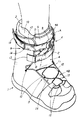
このスノーボード用ブーツの靴本体1について簡単に説明すると、図1,図2,図4に示すように、足首より高さがあってすね部途中までを覆う上部ホールド部9を備え、履き口部2の前側から甲部分3にかけて開口する前側開口部4を備え、この前側開口部4にタン部材5を備え、この前側開口部4に緊締手段を備えている。また、靴本体1(アウターブーツ)内に、すね途中までをホールドする高さのあるインナーブーツ10を着脱自在に設けている。
Briefly describing the
本実施例では、前記靴本体1の甲部分3に存する前側開口部4の下側開口部分4Bに第一緊締手段16を設けると共に、前記靴本体1の前記上部ホールド部9に存する前側開口部4の上側開口部分4Aに本発明の緊締手段6たる第二緊締手段6を設けている。即ち、本実施例では、甲部分3と上部ホールド部9とを一つの緊締手段で緊締する構成ではなく、甲部分3と上部ホールド部9とに別々の緊締手段を設けた構成としている。
In the present embodiment, the first fastening means 16 is provided in the
具体的には、本実施例の第一緊締手段16は、甲部分3の下側開口部分4Bの開口縁部の数箇所に紐通し部12を形成し、この各紐通し部12に靴紐11を通してこの靴紐11で甲部分3を緊締する構成としている。
Specifically, the first tightening means 16 of the present embodiment is formed with
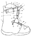
また、本実施例の第二緊締手段6は、前記前側開口部4の上側開口部分4Aに沿設する前記上部ホールド部9の上側左右部と下側左右部とに夫々ベルト通し部A,B,C,Dを設けると共に、この各ベルト通し部A,B,C,Dは、前記タン部材5の前側に位置するように構成している。
Further, the second tightening means 6 of this embodiment includes belt passing portions A and B on the upper left and right sides and the lower left and right portions of the
更に詳しくは、上部ホールド部9の上側開口部分4Aの開口縁より外側の上側左右部と下側左右部との計四箇所から、帯状の取付ベルト13を夫々上側開口部分4Aに向かって突設し、この各取付ベルト13の突出先端に細長い環状を呈するリングを連結して、この各リングをベルト通し部A,B,C,Dとしている。
More specifically, belt-
また、本実施例では、この各ベルト通し部A,B,C,Dを構成する各リングが前記靴本体1の前側開口部4(上側開口部分4A)の開口周縁部より内側に配置してこの各ベルト通し部A,B,C,Dが前記タン部材5の前側に位置するように、前記各取付ベルト13の突出度(長さ寸法)を設定構成している。
In the present embodiment, the rings constituting the belt passing portions A, B, C, and D are disposed on the inner side of the opening peripheral edge of the front opening 4 (
そして、図2に示すように、この上側一方(図面においては上側右方)のベルト通し部Aに緊締ベルト7の一端を通した後折り返し重合し、この重合部を互いに止着(例えば、ビス留め)することで、この緊締ベルト7の一端を上側一方のベルト通し部Aに固定し、この緊締ベルト7の他端を前記タン部材5の前側に配し斜め下方に位置する下側他方のベルト通し部Bに通してから、水平に折り返して下側一方のベルト通し部Cに通し、続いて斜め上方へ折り返して、前記タン部材5の前側で上側一方のベルト通し部Aと下側他方のベルト通し部Bの間に配した緊締ベルト7の途中部とクロスさせてから上側他方のベルト通し部Dに通して、図3中の矢印のようにこの緊締ベルト7の他端を引動することで前記タン部材5と共に前記上部ホールド部9を緊締し得るように構成している。
Then, as shown in FIG. 2, one end of the tightening
また、この際、緊締ベルト7は、下部他方のベルト通し部B,下部一方のベルト通し部C,上部他方のベルト通し部Dのわずか三箇所に対して移動する構成であるため、各ベルト通し部B,C,Dに対する緊締ベルト7の移動摩擦抵抗は比較的小さく、しかも、この下部他方のベルト通し部B,下部一方のベルト通し部C,上部他方のベルト通し部Dは、上側開口部分4Aの開口周縁部より内側に配置しているため、緊締ベルト7と上部ホールド部9とには実質的に摩擦抵抗を生じず、よって、この緊締ベルト7の他端の引動操作は、強い抵抗を生じることなく簡単に引動操作することができる構成としている。出願人の試作実験によると、女性の力でも簡単に緊締ベルト7他端を引動して緊締可能であることが確認されている。
Further, at this time, the tightening
また、この引動した緊締ベルト7の他端を着脱自在に結合して緊締ロック状態とする結合具8をこの緊締ベルト7の一端に設けている。
Further, a
結合具8は、ベルトを通して折り返しすることで結束できる既存のベルト留め具を採用し、このベルト留め具8を緊締ベルト7の一端の重合部を利用して連結している。従って、このような既存のベルト留め具8を採用したことで、結合具8を簡易に設計実現可能であると共に、緊締ベルト7の着脱操作も容易に行われる構成としている。
As the
また、本実施例では、前記緊締ベルト7の一端の重合部を上側開口部分4Aに向けて突出配設すると共に、この重合部の重合寸法(上側一方のベルト通し部Aからの突出度)を、この重合部に連結した前記結合具8たるベルト留め具8が前記上側開口部分4Aの略中央に位置するように設定構成している(図5参照。)。
Further, in this embodiment, the overlapping portion at one end of the tightening
従って、緊締ベルト7の他端を引動緊締操作した際に、この緊締ベルト7の一端が上側一方のベルト通し部Aに固定されているために、この緊締ベルト7の一端に設けた結合具8の位置が緊締ベルト7他端の結合に不都合な位置に移動してしまうようなことがなく、確実に前側開口部4(上側開口部分4A)の略中央位置で緊締ベルト7の一端と他端の結合操作を行うことができる構成としている。
Therefore, when the other end of the tightening
また、この際、図示したように、下側一方のベルト通し部Cから斜め上方へ折り返した緊締ベルト7の他端を、上側一方のベルト通し部Aと下側他方のベルト通し部Bの間に配した緊締ベルト7の途中部の下側へクロスさせて上側他方のベルト通し部Dに通すようにすると、このクロス部分で緊締ベルト7他端がタン部材5に押さえ付けられて挟み込まれた状態となって、引動(緊締調整)後に緊締ベルト7他端が戻る(緩む)ことが阻止されることになり、これによりベルト緩みを気にすることなく結合具8による結合操作を行うことができることになるので、好ましい。
At this time, as shown in the drawing, the other end of the tightening
そして、この結合具8で緊締ベルト7の一端と他端を結合すると、この緊締状態がロックされて靴本体1の上側開口部分4Aに緊締ベルト7が略8の字形に配されることになり、この略8の字形の緊締ベルト7が存する靴本体1の上側開口部分4Aの所定範囲がタン部材5と共に極めて良好に緊締されて上部ホールド部9の足(足首より上方部分)への良好なフィット感が得られることになる構成としている。
Then, when one end and the other end of the tightening
また、本実施例の緊締ベルト7は、軟質性(例えばナイロン製)を有し、幅23〜25mm程度のものを採用している。この程度の幅の緊締ベルト7を採用すると、引動(緊締)操作が容易で、且つ略8の字形に配されるこの緊締ベルト7によって上部ホールド部9の十分な緊締作用が得られることが出願人により確認されている。
Further, the tightening
また、本実施例では、前記緊張ベルト7の一端を固定した上側一方のベルト通し部Aと、緊締ベルト7の他端を通した上側他方のベルト通し部Dとを、前記靴本体1(上部ホールド部9)に対し上下方向に移動可能に設けている。
Further, in this embodiment, the upper belt passing portion A to which one end of the
具体的には、この上側一方のベルト通し部Aと上側他方のベルト通し部Dとが設けられる上側左右部の前記各取付ベルト13の基端を、上部ホールド部の左右部起伏回動自在に枢着した構成とし、この取付ベルト13の起伏動に伴って上側一方のベルト通し部Aと上側他方のベルト通し部Dとが上下移動(起伏動)する構成としている。
Specifically, the base ends of the
従って、これにより特に緊締ベルト7の他端を引動して緊締操作を行う際には、緊締ベルト7他端を斜め上方へ向かって引動するが、この際、図4に示すように上側他方のベルト通し部Dも連動して上方へ起動することで緊締ベルト7がねじれたりすることが防止されて引動操作し易い構成としている。また、この際、緊締ベルト7の一端が固定されている上側一方のベルト通し部Aも適度に動いて引動し易さが向上する構成である。
Accordingly, particularly when the tightening operation is performed by pulling the other end of the tightening
また、本実施例では、上側他方のベルト通し部Dが設けられる取付ベルト13の途中部に、前記結合具8に折り返し結合した緊締ベルト7の他端の長く余った部分を格納するためのベルト格納用リング14を設け、図1に示すようにこのベルト格納用リング14に余った緊締ベルト7の他端を通すことにより、この他端を上部ホールド部9に沿設状態にできて、この他端が邪魔になったり体裁を害することのないようにしている。
Further, in this embodiment, a belt for storing a long remaining portion of the other end of the tightening
また、本実施例では、緊締ベルト7を緩めるためのベルト緩め具15を備えた構成としている。このベルト緩め具15は、例えば図6に示すように、下側他方のベルト通し部Bと下側一方のベルト通し部Cとの間に存する緊締ベルト7に装備しておき、前記結合具8による緊締状態を解除した後でこのベルト緩め具15を図中矢印方向へ引っ張れば、緊締ベルト7を簡単に緩めることができるようにしたものである。
In this embodiment, a
尚、本発明は、本実施例に限られるものではなく、各構成要件の具体的構成は適宜設計し得るものである。 Note that the present invention is not limited to this embodiment, and the specific configuration of each component can be designed as appropriate.
また、本実施例では、スノーボード用ブーツに適用した場合を示したが、例えば、足首部分より高さのある上部ホールド部9を備えた登山靴や、トレッキングシューズや、その他、上部ホールド部9のない靴にも適用可能である。
Further, in this embodiment, the case where the present invention is applied to a snowboard boot is shown. For example, a mountain climbing shoe having an
また、本実施例では、上部ホールド部9にのみ本発明の緊締手段6(第二緊締手段6)を設けた場合を示したが、甲部分3の第一緊締手段16として本発明の緊締手段6を設けても良いし、上部ホールド部9と甲部分3との双方に本発明の緊締手段6を設けても良い。
Further, in the present embodiment, the case where the tightening means 6 (second tightening means 6) of the present invention is provided only in the
尚、甲部分3に緊締手段6を設ける場合、請求項1中の「上側」なる記載は、甲部分3の足首側を指し、請求項1中の「下側」なる記載は、甲部分3のつま先側を指す意味合いで用いている。また、上記第二緊締手段6の説明において、「上側開口部分4A」を「下側開口部分4B」に置き換えることで、甲部分3に緊締手段6を設ける場合についてを説明できる。
When the tightening means 6 is provided on the
1 靴本体
2 履き口部
3 甲部分
4 前側開口部
4A 上側開口部分
4B 下側開口部分
5 タン部材
6 緊締手段
7 緊締ベルト
8 結合具
9 上部ホールド部
A (上側一方の)ベルト通し部
B (下側他方の)ベルト通し部
C (下側一方の)ベルト通し部
D (上側他方の)ベルト通し部
DESCRIPTION OF
Claims (5)
Priority Applications (3)
| Application Number | Priority Date | Filing Date | Title |
|---|---|---|---|
| JP2007263519A JP2009089902A (en) | 2007-10-09 | 2007-10-09 | Boot |
| US12/014,906 US20090090029A1 (en) | 2007-10-09 | 2008-01-16 | Boot |
| KR1020080005717A KR20090036500A (en) | 2007-10-09 | 2008-01-18 | Boot |
Applications Claiming Priority (1)
| Application Number | Priority Date | Filing Date | Title |
|---|---|---|---|
| JP2007263519A JP2009089902A (en) | 2007-10-09 | 2007-10-09 | Boot |
Publications (1)
| Publication Number | Publication Date |
|---|---|
| JP2009089902A true JP2009089902A (en) | 2009-04-30 |
Family
ID=40522061
Family Applications (1)
| Application Number | Title | Priority Date | Filing Date |
|---|---|---|---|
| JP2007263519A Pending JP2009089902A (en) | 2007-10-09 | 2007-10-09 | Boot |
Country Status (3)
| Country | Link |
|---|---|
| US (1) | US20090090029A1 (en) |
| JP (1) | JP2009089902A (en) |
| KR (1) | KR20090036500A (en) |
Cited By (1)
| Publication number | Priority date | Publication date | Assignee | Title |
|---|---|---|---|---|
| WO2010147021A1 (en) | 2009-06-17 | 2010-12-23 | 株式会社 クレブ | Shoe |
Families Citing this family (47)
| Publication number | Priority date | Publication date | Assignee | Title |
|---|---|---|---|---|
| US20060156517A1 (en) | 1997-08-22 | 2006-07-20 | Hammerslag Gary R | Reel based closure system |
| EP2789251A1 (en) | 2004-10-29 | 2014-10-15 | Boa Technology, Inc. | Tightening mechanism for use with a footwear lacing system |
| AU2007360232B2 (en) * | 2007-10-19 | 2011-06-02 | Asics Corporation | Shoe having lace fitting structure |
| EP2805639B2 (en) | 2008-11-21 | 2021-08-18 | Boa Technology, Inc. | Reel based lacing system |
| CN102821635B (en) | 2010-01-21 | 2015-10-14 | 博技术有限公司 | For the guiding device of strapping system |
| KR101875508B1 (en) | 2010-04-30 | 2018-07-06 | 보아 테크놀러지, 인크. | Reel based lacing system |
| US9375053B2 (en) | 2012-03-15 | 2016-06-28 | Boa Technology, Inc. | Tightening mechanisms and applications including the same |
| US10070695B2 (en) | 2010-04-30 | 2018-09-11 | Boa Technology Inc. | Tightening mechanisms and applications including the same |
| US9364046B2 (en) * | 2010-11-10 | 2016-06-14 | Fit Squared Shoes, Llc | Single pull and double pull fit adjustment systems for shoes |
| US9565899B2 (en) * | 2010-11-10 | 2017-02-14 | Fit Squared Shoes, Llc | Single pull and double pull fit adjustment system for shoes |
| KR200465516Y1 (en) * | 2011-04-12 | 2013-02-28 | 강충묵 | boots |
| US9101181B2 (en) | 2011-10-13 | 2015-08-11 | Boa Technology Inc. | Reel-based lacing system |
| KR101344975B1 (en) * | 2012-02-13 | 2013-12-24 | 주식회사 동진레저 | Shoes with dual fastening structure |
| US9248040B2 (en) | 2012-08-31 | 2016-02-02 | Boa Technology Inc. | Motorized tensioning system for medical braces and devices |
| US9516923B2 (en) | 2012-11-02 | 2016-12-13 | Boa Technology Inc. | Coupling members for closure devices and systems |
| EP2916680B1 (en) | 2012-11-06 | 2018-12-26 | Boa Technology Inc. | Devices and methods for adjusting the fit of footwear |
| EP2948014B1 (en) | 2013-01-28 | 2019-06-26 | Boa Technology Inc. | Lace fixation assembly and system |
| US10702409B2 (en) | 2013-02-05 | 2020-07-07 | Boa Technology Inc. | Closure devices for medical devices and methods |
| US9610185B2 (en) | 2013-03-05 | 2017-04-04 | Boa Technology Inc. | Systems, methods, and devices for automatic closure of medical devices |
| US10251451B2 (en) | 2013-03-05 | 2019-04-09 | Boa Technology Inc. | Closure devices including incremental release mechanisms and methods therefor |
| KR102596785B1 (en) | 2013-04-01 | 2023-11-02 | 보아 테크놀러지, 인크. | Methods and devices for retrofitting footwear to include a reel based closure system |
| US10076160B2 (en) | 2013-06-05 | 2018-09-18 | Boa Technology Inc. | Integrated closure device components and methods |
| KR101875716B1 (en) | 2013-06-05 | 2018-08-02 | 보아 테크놀러지, 인크. | Integrated closure device components and methods |
| ITUD20130089A1 (en) * | 2013-06-24 | 2014-12-25 | Calzaturificio Dal Bello S R L | SKI BOOT, OR SIMILAR FOOTWEAR |
| DE112014003135B4 (en) | 2013-07-02 | 2020-12-24 | Boa Technology Inc. | ROLL FOR USE WITH AN OBJECT TIGHTENING SYSTEM AND DEVICES THEREFORE AND METHOD OF ASSEMBLING AN OBJECTIVE TIGHTENING DEVICE |
| EP3653073B1 (en) | 2013-07-10 | 2023-01-11 | Boa Technology Inc. | Closure devices including incremental release mechanisms |
| US9700101B2 (en) | 2013-09-05 | 2017-07-11 | Boa Technology Inc. | Guides and components for closure systems and methods therefor |
| KR20230084599A (en) | 2013-09-13 | 2023-06-13 | 보아 테크놀러지, 인크. | Reel based closure device and method therefore |
| EP3071159A1 (en) | 2013-11-18 | 2016-09-28 | Boa Technology, Inc. | Methods and devices for providing automatic closure of prosthetics and orthotics |
| DE102014100150B4 (en) * | 2014-01-08 | 2020-09-17 | Johannes Helmut Steuerwald | shoe |
| USD835976S1 (en) | 2014-01-16 | 2018-12-18 | Boa Technology Inc. | Coupling member |
| USD751281S1 (en) | 2014-08-12 | 2016-03-15 | Boa Technology, Inc. | Footwear tightening reels |
| USD767269S1 (en) | 2014-08-26 | 2016-09-27 | Boa Technology Inc. | Footwear tightening reel |
| US20160058127A1 (en) | 2014-08-28 | 2016-03-03 | Boa Technology Inc. | Devices and methods for enhancing the fit of boots and other footwear |
| USD758061S1 (en) | 2014-09-08 | 2016-06-07 | Boa Technology, Inc. | Lace tightening device |
| US10182935B2 (en) | 2014-10-01 | 2019-01-22 | Ossur Hf | Support for articles and methods for using the same |
| WO2016057697A1 (en) | 2014-10-07 | 2016-04-14 | Boa Technology Inc. | A tension adjustment mechanism and a method for adjusting the fit of a shoe |
| USD776421S1 (en) | 2015-01-16 | 2017-01-17 | Boa Technology, Inc. | In-footwear lace tightening reel |
| US10004297B2 (en) | 2015-10-15 | 2018-06-26 | Boa Technology Inc. | Lacing configurations for footwear |
| WO2018026957A1 (en) | 2016-08-02 | 2018-02-08 | Boa Technology Inc. | Tension member guides of a lacing system |
| US20190208863A1 (en) * | 2016-08-31 | 2019-07-11 | Fit Squared Shoes, Llc | Double Pull Squared-Cord Shoe Closure System |
| US10149514B2 (en) | 2016-08-31 | 2018-12-11 | Fit Squared Shoes, Llc | Single pull squared-cord shoe closure system |
| KR102494446B1 (en) | 2016-12-09 | 2023-02-01 | 보아 테크놀러지, 인크. | Reel-based closure system |
| US10543630B2 (en) | 2017-02-27 | 2020-01-28 | Boa Technology Inc. | Reel based closure system employing a friction based tension mechanism |
| US11357279B2 (en) | 2017-05-09 | 2022-06-14 | Boa Technology Inc. | Closure components for a helmet layer and methods for installing same |
| US10772384B2 (en) | 2017-07-18 | 2020-09-15 | Boa Technology Inc. | System and methods for minimizing dynamic lace movement |
| CN114072024A (en) | 2019-05-01 | 2022-02-18 | Boa科技股份有限公司 | Reel-based closure system |
-
2007
- 2007-10-09 JP JP2007263519A patent/JP2009089902A/en active Pending
-
2008
- 2008-01-16 US US12/014,906 patent/US20090090029A1/en not_active Abandoned
- 2008-01-18 KR KR1020080005717A patent/KR20090036500A/en not_active Application Discontinuation
Cited By (4)
| Publication number | Priority date | Publication date | Assignee | Title |
|---|---|---|---|---|
| WO2010147021A1 (en) | 2009-06-17 | 2010-12-23 | 株式会社 クレブ | Shoe |
| US8782926B2 (en) | 2009-06-17 | 2014-07-22 | Kabushiki Kaisha Kurebu | Footwear having a lacing system |
| US8806778B2 (en) | 2009-06-17 | 2014-08-19 | Kabushiki Kaisha Kurebu | Footwear having lacing system connecting footwear and inner lining |
| EP3005895A1 (en) | 2009-06-17 | 2016-04-13 | Kabushiki Kaisha Kurebu | Footwear |
Also Published As
| Publication number | Publication date |
|---|---|
| US20090090029A1 (en) | 2009-04-09 |
| KR20090036500A (en) | 2009-04-14 |
Similar Documents
| Publication | Publication Date | Title |
|---|---|---|
| JP2009089902A (en) | Boot | |
| US7487603B2 (en) | Article of footwear with fastening system | |
| EP3005895B1 (en) | Footwear | |
| JP3120861U (en) | Sports shoes | |
| US6378230B1 (en) | Lace-less shoe | |
| US20080028641A1 (en) | Snowboard boot | |
| JP2004041666A (en) | Boots for snowboard | |
| JP2005152490A (en) | Shoes which fit to foot with belt | |
| JP2018532554A (en) | Footwear closure system | |
| JP2006187545A (en) | Footwear for correcting hallux valgus | |
| KR200467145Y1 (en) | Footwear-string type footwear | |
| KR200409510Y1 (en) | Tying tool for shoelace | |
| JP2003289901A (en) | Snowboard boots | |
| JP2001149113A (en) | Working shoes | |
| JP5462388B1 (en) | One-touch band for shoes | |
| WO2011157050A1 (en) | Shoelace tying device | |
| JP6637678B2 (en) | Foot fixing mechanism for footwear | |
| KR20110007917U (en) | Fixing device of shoestrings knot | |
| JP6167366B2 (en) | Tie fastener | |
| JP2911756B2 (en) | Sports shoes | |
| KR20010008137A (en) | shoe lace binder | |
| KR100662794B1 (en) | Tying tool for shoelace | |
| WO2012174269A1 (en) | Boot with lace tensioning system | |
| JP2008132289A (en) | Shoe fastener | |
| KR200453361Y1 (en) | Shoe fixture |
Legal Events
| Date | Code | Title | Description |
|---|---|---|---|
| A131 | Notification of reasons for refusal |
Free format text: JAPANESE INTERMEDIATE CODE: A131 Effective date: 20090202 |
|
| A521 | Written amendment |
Free format text: JAPANESE INTERMEDIATE CODE: A523 Effective date: 20090402 |
|
| A02 | Decision of refusal |
Free format text: JAPANESE INTERMEDIATE CODE: A02 Effective date: 20090615 |