KR20100123737A - Track-guided self-climbing shuttering system with climbing rail extension pieces - Google Patents
Track-guided self-climbing shuttering system with climbing rail extension pieces Download PDFInfo
- Publication number
- KR20100123737A KR20100123737A KR1020107021201A KR20107021201A KR20100123737A KR 20100123737 A KR20100123737 A KR 20100123737A KR 1020107021201 A KR1020107021201 A KR 1020107021201A KR 20107021201 A KR20107021201 A KR 20107021201A KR 20100123737 A KR20100123737 A KR 20100123737A
- Authority
- KR
- South Korea
- Prior art keywords
- rail
- lift
- lifting
- concrete
- formwork system
- Prior art date
Links
Images


Classifications
-
- E—FIXED CONSTRUCTIONS
- E04—BUILDING
- E04G—SCAFFOLDING; FORMS; SHUTTERING; BUILDING IMPLEMENTS OR AIDS, OR THEIR USE; HANDLING BUILDING MATERIALS ON THE SITE; REPAIRING, BREAKING-UP OR OTHER WORK ON EXISTING BUILDINGS
- E04G21/00—Preparing, conveying, or working-up building materials or building elements in situ; Other devices or measures for constructional work
-
- E—FIXED CONSTRUCTIONS
- E04—BUILDING
- E04B—GENERAL BUILDING CONSTRUCTIONS; WALLS, e.g. PARTITIONS; ROOFS; FLOORS; CEILINGS; INSULATION OR OTHER PROTECTION OF BUILDINGS
- E04B1/00—Constructions in general; Structures which are not restricted either to walls, e.g. partitions, or floors or ceilings or roofs
- E04B1/35—Extraordinary methods of construction, e.g. lift-slab, jack-block
- E04B1/3505—Extraordinary methods of construction, e.g. lift-slab, jack-block characterised by the in situ moulding of large parts of a structure
-
- E—FIXED CONSTRUCTIONS
- E04—BUILDING
- E04G—SCAFFOLDING; FORMS; SHUTTERING; BUILDING IMPLEMENTS OR AIDS, OR THEIR USE; HANDLING BUILDING MATERIALS ON THE SITE; REPAIRING, BREAKING-UP OR OTHER WORK ON EXISTING BUILDINGS
- E04G11/00—Forms, shutterings, or falsework for making walls, floors, ceilings, or roofs
- E04G11/06—Forms, shutterings, or falsework for making walls, floors, ceilings, or roofs for walls, e.g. curved end panels for wall shutterings; filler elements for wall shutterings; shutterings for vertical ducts
- E04G11/20—Movable forms; Movable forms for moulding cylindrical, conical or hyperbolical structures; Templates serving as forms for positioning blocks or the like
- E04G11/28—Climbing forms, i.e. forms which are not in contact with the poured concrete during lifting from layer to layer and which are anchored in the hardened concrete
Abstract
빌딩 섹터 내 레일 가이드 방식의 자가 상승 폼워크 시스템(10)에 있어서, 상승 레일(18)이 상승 슈(24, 26, 34, 36) 내에서 가이드되고, 상기 상승 레일은 비계 유닛 내로 통합된다. 상기 비계 유닛은 또한 작업 플랫폼(12) 및 마감 플랫폼(16)을 포함하며, 이들은 또한 상기 상승 레일(18)에 부착되어 있다. 상승 레일 연장부(20, 22)가 상기 상승 레일(18)의 자유 단부 상에 장착될 수 있고 이에 견고하게 부착될 수 있다. 상기 상승 레일 연장부(20, 22)의 길이는 상기 상승 레일(18)보다 짧다.In a self guided formwork system 10 in the form of a rail guide in a building sector, the lift rails 18 are guided in the lift shoes 24, 26, 34, 36, which are integrated into the scaffold unit. The scaffolding unit also includes a work platform 12 and a finishing platform 16, which are also attached to the lift rail 18. Lift rail extensions 20, 22 may be mounted on and securely attached to the free end of the lift rail 18. The length of the lift rail extensions 20, 22 is shorter than the lift rail 18.
Description
본 발명은 비계 유닛 내로 통합되고 상승 슈 내에서 가이드되는 상승 레일을 갖는 빌딩 섹터 내 레일 가이드 방식의 자가 상승 폼워크 시스템으로서, 상기 상승 슈들이 경화 콘크리트 섹션 및 콘크리트 섹션들에 각각 부착될 수 있고, 상기 상승 레일이 상기 상승 슈 내에서 이동가능하고 가이드되고 유지되는 레일 가이드 방식의 자가 상승 폼워크 시스템에 관한 것이다.The present invention is a rail guided self-raising formwork system in a building sector having a rising rail integrated into a scaffolding unit and guided in a rising shoe, wherein the rising shoes can be attached to the hardened concrete section and the concrete sections, respectively, A rail guided self-raising formwork system in which the lifting rails are movable, guided and held in the lifting shoes.
이러한 자가 상승 폼워크 시스템은 국제 특허 출원 WO 2007/000139 A1, WO 2007/00136 A1, WO 2007/000134 A1 및 WO 2007/000137 A1을 통하여 공지되어 있다.Such self-raising formwork systems are known through the international patent applications WO 2007/000139 A1, WO 2007/00136 A1, WO 2007/000134 A1 and WO 2007/000137 A1.
공지의 레일 가이드 방식의 자가 상승 폼워크 시스템에서는, 적어도 두 개의 플로어 또는 콘크리트 섹션이 폼워크 시스템과 함께 건설되어야 자가 상승 폼워크를 사용할 수 있다. 이는 상기 상승 레일이 다양한 콘크리트 섹션들에 부착되는 상승 슈 내에서 가이드, 유지 및 이동되기 때문이다.In known rail guided self-elevating formwork systems, at least two floor or concrete sections must be constructed with the formwork system to use the self-elevating formwork. This is because the lift rails are guided, held and moved in the lift shoes attached to the various concrete sections.
상기 상승 슈를 하나의 콘크리트 섹션으로부터 다른 콘크리트 섹션으로 이동시키기 위해서는, 상승 절차에 필요한 개별적인 작업 공정들을 크레인을 사용하지 않고 수행할 수 있도록 대면적 비계 유닛이 부가적으로 요구된다. In order to move the lift shoe from one concrete section to another, a large area scaffolding unit is additionally required to perform the individual work processes required for the lift procedure without the use of a crane.
공지된 바에 따르면, 예컨대, WO 2007/000139 A에서는, 상승 레일의 길이로 인하여, 상승 레일의 하부 자유 단부가 제1 콘크리트 섹션이 설치되는 그라운드 또는 제1 콘크리트 섹션 아래 건설되어 있을 수 있는 플로어 천장과 충돌하지 않도록, 자가 상승 폼워크 시스템 사용시 충분한 구조적 높이에 도달하여야 한다. 보통, 자가 상승 폼워크 시스템의 사용이 가능하도록 하기 위해서는, 처음에 두 개의 플로어가 완성되어야 한다. 따라서, 상승 레일의 길이는 각각 건설될 상기 플로어들 및 콘크리트 섹션들의 높이 및 더 높은 콘크리트 섹션의 경우 요구되는 마감 플랫폼의 존재에 의하여 결정된다. 따라서, 상기 상승 레일의 길이는 건설될 콘크리트 섹션의 높이보다 훨씬 크다. As is known, for example, in WO 2007/000139 A, due to the length of the rising rail, the lower free end of the rising rail may be constructed with a floor ceiling, which may be constructed under the ground or first concrete section in which the first concrete section is installed. In order to avoid collisions, a sufficient structural height must be reached when using a self climbing formwork system. Usually, to enable the use of a self-elevating formwork system, two floors must first be completed. Thus, the length of the rising rail is determined by the height of the floors and concrete sections to be built, respectively, and the presence of the finishing platform required for the higher concrete sections. Thus, the length of the lift rail is much greater than the height of the concrete section to be built.
본 발명의 목적은 공지의 레일 가이드 방식의 자가 상승 폼워크 시스템을 광범위한 응용 분야에 사용가능하도록 단순화하는 것이다.It is an object of the present invention to simplify the known rail guided self-lifting formwork system for use in a wide range of applications.
상기 목적은 청구항의 내용들에 의하여 달성된다. 종속 청구항들은 본 발명의 내용의 바람직한 실시예를 나타낸다. This object is achieved by the contents of the claims. Dependent claims represent preferred embodiments of the subject matter of the present invention.
상승 레일 보다 짧은 길이의 상승 레일 연장부가 상기 상승 레일의 자유 단부에 부착될 수 있다.A lift rail extension of shorter length than the lift rail can be attached to the free end of the lift rail.
이러한 유형의 상승 레일의 실시예에 따르면, 안전성 위험 증가를 초래하지 않고 더 짧은 상승 레일을 이용하여 상승 절차를 수행하는 것이 가능하다. 안전한 자가 상승 절차를 위해서는, 서로로부터 이격되어 배열되는 적어도 두 개의 평행한 상승 레일이 서로의 상부에 배열되는 적어도 두 개의 상승 슈 내에 각각 항상 유지되어야 하며, 상승 절차 동안, 상기 상승 레일은 이들에 부착되어 있는 상승 레일 연장부를 경유하여 추가의 제3 상승 슈 쌍 내로 이동하고, 다른 것의 상부에 배열되는 상기 3 쌍의 상승 슈 중 제1 쌍이 제거될 때까지 거기서 유지되어, 예컨대 상기 쌍을 상기 제3 상승 슈 위의 제4 상승 슈로서 다시 사용할 수 있다. 이러한 상승 절차를 위하여, 상기 해당 상승 레일은 건설될 플로어 높이보다 상당히 큰 최소 길이를 가져야 한다. 상승 레일 연장부를 사용함으로써, 상기 상승 레일을 그 전체 길이가 건설될 콘크리트 섹션 위로 돌출되지 않을 정도로 단축시킬 수 있다; 즉, 상승 레일은 실질적으로 상기 상승 레일이 상승 슈를 경유하여 부착되어 있는 경화된 콘크리트 섹션의 높이에 상응하는 길이를 가진다. According to an embodiment of this type of lift rail, it is possible to carry out the lift procedure using shorter lift rails without causing an increased safety risk. For a safe self-raising procedure, at least two parallel lifting rails spaced apart from each other must always be maintained in each of the at least two lifting shoes arranged above each other, during which the lifting rails are attached to them. Is moved into a further third lift shoe pair via a raised rail extension, and is held there until the first of the three pairs of lift shoes arranged on top of the other is removed, e.g. It can be used again as a fourth rising shoe on the rising shoe. For this ascent procedure, the corresponding elevated rails must have a minimum length significantly greater than the floor height to be constructed. By using lift rail extensions, the lift rails can be shortened to such an extent that their entire length does not protrude over the concrete section to be built; That is, the lift rail has a length substantially corresponding to the height of the hardened concrete section to which the lift rail is attached via the lift shoe.
이는 본 발명에 따라 단축된 상승 레일 및 상승 레일 쌍이 각각 제1 플로어 또는 제1 콘크리트 섹션의 완성 후에 이미 사용될 수 있음을 의미한다. 제2 콘크리트 섹션의 완성 후의 상승 절차를 위하여, 상기 적어도 두 개의 상승 레일 연장부가 상승 레일의 자유 상부 단부에 견고하게 연결되어, 상승 레일의 상승 절차 동안 상기 상승 레일이 가장 최근에 건설되고 경화된 콘크리트 섹션에 부착되어 있는 상승 슈 내로 도입될 수 있다. 동시에, 상기 상승 레일(들)은 아래 배열되는 두 개의 상승 슈 내에 여전히 유지되어, 충분한 안전성을 제공하면서 상승 절차를 수행할 수 있다.This means that according to the invention the shortened lift rail and lift rail pair can already be used after completion of the first floor or first concrete section, respectively. For the ascending procedure after completion of the second concrete section, the at least two rise rail extensions are firmly connected to the free upper end of the rise rail such that the rise rail is the most recently constructed and hardened concrete during the rise procedure of the rise rail. It can be introduced into a lift shoe attached to the section. At the same time, the lift rail (s) can still be held in two lift shoes arranged below, to carry out the lift procedure while providing sufficient safety.
새로운 콘크리팅 절차를 위하여, 상승 레일 연장부는, 상승 레일이 서로의 상부에 부착되는 한 쌍의 상승 슈 내에서 유지 가이드될 경우, 상승 레일의 상부 단부로부터 다시 제거된다. 이러한 방법으로, 콘크리팅 절차 동안 그 상승 레일이 콘크리트 섹션 또는 완성된 플로어 위로 돌출되지 않는 레일 가이드 방식의 자가 상승 폼워크 시스템이 이용될 수 있다. 상기 상승 레일들은 본질적으로 콘크리팅될 섹션의 높이에 상응하며 각각 건설될 콘크리트 섹션의 높이보다 더 짧은 길이를 가진다. For a new concrete procedure, the lift rail extensions are removed again from the upper end of the lift rails when they are guided in a pair of lift shoes that are attached to the top of each other. In this way, a rail guided self-raising formwork system can be used during which the rising rail does not protrude above the concrete section or the finished floor. The rising rails essentially correspond to the height of the section to be concrete and each has a length shorter than the height of the concrete section to be constructed.
유리하게, 적어도 상승 레일의 하부 자유 단부 상에, 상승 레일보다 짧은 길이의 상승 레일 연장부가 탈착가능하고/하거나 피보팅 방식으로 부착될 수 있다. Advantageously, at least on the lower free end of the lift rail, a lift rail extension of shorter length than the lift rail may be detachably and / or pivotally attached.
본 발명의 자가 상승 폼워크 시스템은 제1 콘크리트 섹션의 완성 후에 이미 사용될 수 있다. 이를 위하여, 상기 상승 레일 연장부가 처음에 상승 레일의 하부 자유 단부로부터 탈착되거나 이에 피보팅되는 방식으로 부착된다. 상기 상승 레일은 본질적으로 콘크리트 섹션의 높이에 상응하는 길이를 갖도록 짧게 선택된다. 그렇다면, 상기 상승 레일의 하부 자유 단부는 제1 콘크리트 섹션이 건설되는 그라운드 또는 상기 제1 콘크리트 섹션 아래에 건설될 플로어 천장과 더 이상 충돌하지 않는다. 충분한 플로어 높이에 도달하면, 상기 상승 레일 연장부는 탈착가능하게 및/또는 피보팅가능하게 상승 레일의 하부 자유 단부에 부착되어, 예컨대 그 위에 마감 플랫폼을 제공할 수 있다.The self climbing formwork system of the present invention can already be used after completion of the first concrete section. For this purpose, the lift rail extension is first attached in such a way that it is detached or pivoted from the lower free end of the lift rail. The lift rail is selected short so as to have a length that essentially corresponds to the height of the concrete section. If so, the lower free end of the rising rail no longer collides with the ground on which the first concrete section is to be built or the floor ceiling to be built under the first concrete section. Once a sufficient floor height is reached, the lift rail extension can be detachably and / or pivotally attached to the lower free end of the lift rail, for example to provide a finishing platform thereon.
본 발명의 추가적인 실시예에서, 상기 상승 레일 연장부는 건설될 콘크리트 섹션의 높이보다 짧다. 한편으로는, 원하는 처리능력이 따라서 얻어지며, 다른 한편으로는, 상기 상승 레일 연장부의 길이를 통하여, 각각의 상승 절차에서 연장된 상승 레일이 다음 상승 슈에 안전하게 도달하고 거기서 유지될 수 있음을 보증한다. 이와 관련하여, 상기 상승 레일 연장부의 길이는 바람직하게 서로의 상부에 직접적으로 배열되는 두 개의 상승 슈 사이의 거리의 절반과 동등하거나 이보다 크다.In a further embodiment of the invention, the lift rail extension is shorter than the height of the concrete section to be built. On the one hand, the desired processing capacity is thus obtained, and on the other hand, through the length of the lift rail extension, it is ensured that the lift rails extended in each lift procedure can safely reach and remain on the next lift shoe. do. In this regard, the length of the lift rail extensions is preferably equal to or greater than half of the distance between the two lift shoes arranged directly on top of each other.
상기 상승 레일 연장부가 잠금핀에 의하여 상승 레일의 자유 단부에 연결되면, 간단한 구조적 수단으로 상기 상승 레일의 자유 단부와 상승 레일 연장부 사이를 견고하게 연결할 수 있다. 동시에, 각각의 완성된 상승 절차 후에 상승 레일 연장부가 상기 상승 레일로부터 다시 제거되므로, 이러한 유형의 연결은 신속하고 단순히 다시 탈착가능하여, 외부 폼워크 및/또는 내부 폼워크를 새로운 콘크리트 섹션이 건설되는 위치로 가져올 수 있다. When the lift rail extension is connected to the free end of the lift rail by a locking pin, a simple structural means can firmly connect between the free end of the lift rail and the lift rail extension. At the same time, after each completed lifting procedure the lifting rail extension is again removed from the lifting rail, so this type of connection can be quickly and simply detachable so that a new concrete section can be constructed for the outer formwork and / or the inner formwork. You can import it to a location.
각각의 상승 레일 연장부가 두 개의 잠금핀에 의하여 상승 레일의 자유 단부로 연결되는 것이 유리하다. 한편, 단지 하나의 잠금핀이 사용된다면 연접이 가능하고, 서로 이격되어 있는 두 개의 잠금핀이 상승 레일을 상승 레일 연장부에 연결하는데에 사용된다면 상기 상승 레일과 상승 레일 연장부 사이의 견고한 연결이 달성된다. Each lift rail extension is advantageously connected to the free end of the lift rail by two locking pins. On the other hand, if only one locking pin is used, it can be connected, and if two locking pins spaced apart are used to connect the rising rail to the rising rail extension, a firm connection between the rising rail and the rising rail extension is necessary. Is achieved.
상기 상승 레일 및 상승 레일 연장부가 지지핀 및 경우에 따라 스페이서, 연결 핀에 의하여 서로 이격되어 결합되는 두 개의 프로파일 레일로 이루어진다면, 본 발명에 따르는 상기 레일 가이드 방식의 자가 상승 폼워크 시스템의 단순화된 구조를 얻을 수 있다. 이는 상승 레일 연장부가 이러한 방식으로 고안된 상승 레일에 단순히 커플링될 수 있으며, 동시에 상기 상승 레일 내에 예상되는 배열을 일련의 지지핀들에 의하여 상승 레일 연장부 내에 방해없이 계속할 수 있다는 이점을 가진다. If the rising rail and the rising rail extension are composed of two profile rails spaced apart from each other by a support pin and, optionally, a spacer and a connecting pin, the rail guide type self-raising formwork system according to the present invention is simplified. The structure can be obtained. This has the advantage that the lift rail extension can simply be coupled to the lift rail designed in this way, while at the same time continuing the arrangement expected in the lift rail in the lift rail extension by a series of support pins.
상기 레일 가이드 방식의 자가 상승 폼워크 시스템은 작업 플랫폼과 마감 플랫폼이 형성되는 비계 유닛을 가진다. 상기 상승 레일은 상기 비계 유닛 내로 통합된다. 본 발명에 따르는 상기 단축된 상승 레일과 함께, 상기 비계 유닛은 하나의 작업 플랫폼과 하나의 마감 플랫폼을 갖는 것으로 충분하다. 종래 기술에서와 같은 중간 플랫폼이 본 발명에 실시예에 따른 상기 자가 상승 폼워크 시스템 내에 제공될 수 있다. 이는 전체 레일 가이드 방식의 시스템을 상당히 단순화시킨다. The rail guided self-lifting formwork system has a scaffold unit in which a work platform and a finishing platform are formed. The lift rail is integrated into the scaffold unit. With the shortened lift rail according to the invention, it is sufficient for the scaffolding unit to have one working platform and one finishing platform. An intermediate platform as in the prior art may be provided within the self-elevating formwork system according to embodiments of the present invention. This greatly simplifies the entire rail guided system.
유리하게, 이동가능한 외부 또는 내부 폼워크가 상기 작업 플랫폼 상에 ㅈ된장착된다. 필요하다면, 상기 외부 또는 내부 폼워크는 상기 작업 플랫폼 상에서, 한편으로는 상승 슈가 작업 플랫폼 상에 경화된 콘크리트 섹션에 가장 용이하게 부착되거나 이로부터 제거될 수 있고, 다른 한편으로는 외부 또는 내부 폼워크가 추가의 콘크리트 섹션이 건설될 수 있는 작업 플랫폼 상의 위치로 이동될 수 있는 방식으로 이동될 수 있다. Advantageously, a movable outer or inner formwork is mounted on the work platform. If desired, the outer or inner formwork can be most easily attached to or removed from the cured concrete section on the work platform, on the one hand the raised sugar work platform, and on the other hand the outer or inner formwork. Can be moved in such a way that additional concrete sections can be moved to a location on the work platform on which they can be constructed.
상승 실린더가 상기 상승 슈 상에 장착되어, 이들 상승 실린더의 도움으로 전체 비계 유닛을 완성된 콘크리트 섹션 상에서 상향 또는 필요하다면 심지어 하향으로 밀 수 있다. 상승 절차가 완성되면, 상승 실린더는 상승 슈로부터 제거되고 더 높거나 낮은 위치의 상승 슈 상에 다시 장착될 수 있다. 상기 장착된 상승 실린더는 각각 상승 실린더의 자유 단부 상에 형성되는 캐치를 경유하여 상승 레일 및 상승 레일 연장부 각각의 지지핀 내로 맞물릴 수 있다. 상승 실린더가 밖으로 이동하면, 상승 레일 연장부를 갖는 상승 레일이 전체 비계 유닛과 함께 이동한다. Lift cylinders can be mounted on the lift shoes, with the aid of these lift cylinders, the entire scaffolding unit can be pushed upwards or even downwards on the finished concrete section. Once the lift procedure is complete, the lift cylinder can be removed from the lift shoe and remounted on the lift shoe at a higher or lower position. The mounted lift cylinders may engage into support pins of the lift rails and lift rail extensions, respectively, via catches formed on the free ends of the lift cylinders, respectively. When the lift cylinder moves out, the lift rail with the lift rail extension moves with the entire scaffold unit.
본 발명의 바람직한 실시예에서, 마감 플랫폼의 구성 성분이 상승 레일 연장부의 하부 자유 단부 상에 제공되며, 이는 다른 반대 단부과 함께 연접식으로 상승 레일의 하부 자유 단부와 연결된다. 이는 마감 플랫폼이 제1 콘크리트 섹션 상에서도 비계 유닛 상으로 장착될 수 있다는 이점을 가진다. 상기 상승 절차가 제1 콘크리트 섹션 상에서 개시되면, 마감 플랫폼이 여전히 제1 콘크리트 섹션이 건설된 베이스 상에 정지되며, 상승 절차가 진행됨에 따라 상기 마감 플랫폼 구성 요소가 부착된 상승 레일 연장부가 완성된 제1 콘크리트 섹션으로 피보팅되고 마감 플랫폼이 정렬된다. In a preferred embodiment of the invention, the components of the finishing platform are provided on the lower free end of the lift rail extension, which is connected with the lower free end of the lift rail in tandem with the other opposite end. This has the advantage that the finishing platform can be mounted onto the scaffolding unit even on the first concrete section. When the ascending procedure commences on the first concrete section, the finishing platform is still stopped on the base on which the first concrete section is constructed, and as the ascending procedure proceeds the finishing rail extension to which the finishing platform component is attached is completed. 1 Pivoted to concrete section and finish platform aligned.
첨부 도면에 대한 기재로부터 추가적인 이점을 이해할 수 있다. 동등하게, 본 발명에 따라, 상기 인용된 특징들 및 추가적으로 기재되는 특징들 각각을 개별적으로 또는 조합하여 사용할 수 있다. 상기한 실시예들은 완전한 열거가 아닌 예로서 간주되어야 한다. 본 발명은 도면에 도시되고 도면의 실시예에 근거하여 더욱 상세히 설명된다. Additional advantages may be appreciated from the description of the accompanying drawings. Equally, according to the invention, each of the above-cited features and the additionally described features may be used individually or in combination. The above embodiments should be considered as examples rather than a complete enumeration. The invention is illustrated in the drawings and explained in more detail based on the embodiments of the drawings.
본 발명에 따르면, 공지의 레일 가이드 방식의 자가 상승 폼워크 시스템을 광범위한 응용 분야에 사용가능하도록 단순화시킬 수 있으며, 안전성 위험 증가를 초래하지 않고 더 짧은 상승 레일을 이용하여 상승 절차를 수행하는 것이 가능하다. According to the present invention, a known rail guided self-raising formwork system can be simplified for use in a wide range of applications, and it is possible to perform an ascending procedure using shorter lifting rails without causing an increased safety risk. Do.
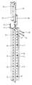
도 1은 레일 가이드 방식의 자가 상승 폼워크 시스템을 이용하여 콘크리트 섹션의 측면을 따라 배치될 수 있는 작업 플랫폼 상에 외부 폼워크를 포함하는 레일 가이드 방식의 자가 상승 폼워크 시스템의 측면도이다.
도 2는 도 1의 구성 요소에 대한 확대 측면도이다.
도 3은 상승 레일 및 상승 레일 연장부 및 이들의 조합 방식에 대한 3차원도이다.
도 4는 상승 레일 연장부의 3차원도이다.
도 5는 본 발명에 따르는 상승 레일 연장부의 정면도이다.
도 6은 작업 플랫폼 상에 내부 폼워크를 포함하는 본 발명에 따르는 레일 가이드 방식의 자가 상승 폼워크 시스템을 이용한, 상승 순서 a) 내지 e)로 구분된 상승 절차의 순서를 도시한다.
도 7은 외부 폼워크를 포함하는 작업 플랫폼 및 마감 플랫폼을 갖는 비계 유닛을 갖는 본 발명에 따르는 레일 가이드 방식의 자가 상승 폼워크 시스템을 이용한 상승 절차의 순서를 상승 순서 a) 내지 d)로 도시한다.1 is a side view of a rail guided self-raising formwork system including an outer formwork on a work platform that can be disposed along the side of a concrete section using a rail guided self-raising formwork system.
FIG. 2 is an enlarged side view of the component of FIG. 1. FIG.
3 is a three-dimensional view of the lift rails and lift rail extensions and combinations thereof.
4 is a three-dimensional view of the lift rail extension.
5 is a front view of the lift rail extension according to the invention.
6 shows the sequence of the ascending procedure divided into ascending order a) to e) using a rail guided self-elevating formwork system according to the invention comprising an inner formwork on the work platform.
7 shows the sequence of ascending procedures a) to d) using a rail guided self-elevating formwork system according to the present invention having a scaffolding unit with a working platform comprising an external formwork and a finishing platform. .
도면에서, 상기 레일 가이드 방식의 자가 상승 폼워크 시스템은 매우 개략적인 방식으로 도시되며, 개별적인 특징들은 일정한 비율인 것으로 이해되어서는 안된다.In the figure, the rail guided self-raising formwork system is shown in a very schematic manner, and individual features should not be understood to be of a constant ratio.
도 1에서, (10)은 외부 폼워크(13)가 설치되는 작업 플랫폼(12)을 비계 유닛 상에 갖는 레일 가이드 방식의 자가 상승 폼워크 시스템을 나타낸다. 상기 외부 폼워크(13)는 화살표(14)의 방향으로 작업 플랫폼(12) 상에서 이동할 수 있다. 마감 플랫폼(16) 또한 상기 비계 유닛 내로 통합되고, 작업 플랫폼(12)과 마찬가지로 상승 레일(18)에 부착된다. 레일 가이드 방식의 자가 상승 폼워크 시스템(10)의 측면도만이 도시되며, 도시되는 상승 레일(18)에 평행하게 상승 레일(18)로부터 이격되어 이어지는 추가의 상승 레일(18)은 보이지 않는다. 이러한 방식으로, 상기 비계 유닛이 상승 레일(18)에 의하여 결합된다(종래 기술).In FIG. 1,
상기 상승 레일(18)의 상부 자유 단부 상에 제1 상승 레일 연장부(20)가 장착되고, 상승 레일(18)의 하부 자유 단부 상에 제2 상승 레일 연장부(22)가 부착된다. 상기 상승 레일(18)은 상승 슈들(24, 26) 내에 이동가능한 방식으로 수용된다. 상기 상승 슈(26) 상에 상승 실린더(28)가 장착되며, 상기 상승 실린더의 자유 단부 상에 캐치(30)를 가지고, 상기 캐치는 제1 상승 레일 연장부(20)의 지지핀(32) 아래 맞물린다. 지지핀들(32)이 상기 제1 상승 레일 연장부(20)를 따라, 제2 상승레일 연장부(22)를 따라, 및 상승 레일(18)을 따라 소정의 간격으로 배열된다. 상기 상승 슈들(24, 26) 또한, 지지핀(32) 아래 맞물리며 상기 상승 레일(18) 및 상승 레일 연장부(20) 각각을 제 위치에 수용할 수 있는 공지의 캐치를 가진다. 전체 레일 가이드 방식의 자가 상승 폼워크 시스템이, 상승 레일(18) 또는 상승 레일 연장부(20)의 상응하는 지지핀(32)이 걸리는 캐치에 의하여 상승 슈들(24, 26) 내에 수용된다. The first
상승 슈들(34, 36)이 앵커 지점(38)을 경유하여 콘크리트 섹션에 부착된다. 도면에서, 제1 콘크리트 섹션(40), 제2 콘크리트 섹션(42) 및 제3 콘크리트 섹션(44)이 도시된다. 이들 콘크리트 섹션들(40, 42, 44)은 경화되고 레일 가이드 방식의 자가 상승 폼워크 시스템(10)의 부하를 견딜 수 있다. 상기 콘크리트 섹션내에, 앵커 지점(38)이 제공되며, 이를 경유하여 레일 가이드 방식의 자가 상승 폼워크 시스템(10)을 위한 상승 슈가 부착된다. 도면에서, 천장 부분(45, 46, 47) 또한 도시되며, 이는 각각의 콘크리트 섹션들을 한쪽으로 제한한다. 콘크리트 섹션들(40, 42, 44) 각각을 생산하기 위해서, 도시되는 외부 폼워크(13)에 상응하는 내부 폼워크가 설치되는 것으로 이해된다. 상기 천장 섹션들(45, 46, 47)은 공지의 천장 폼워크 시스템에 의하여 생산된다(도시하지 않음).Lift
도 2는 도 1의 제2 콘크리트 섹션(42) 및 제3 콘크리트 섹션(44)의 세부적인 확대 측면도이다. 천장 섹션(46)이 도시된다. 상승 슈들(26, 34)이 제2 및 제3 콘크리트 섹션들(42, 44)의 앵커 지점(38) 내에 부착된다. 공지의 방식으로, 상기 상승 슈(26) 상에 상승 실린더(28)가 장착되며, 이는 캐치(30)에 의하여 제1 상승 레일 연장부(20)의 지지핀(32) 아래 맞물린다. 제1 상승 레일 연장부(20)를 따라, 또한 상승 레일(18)을 따라, 지지핀들(32)이 제공되며, 이들은 모두 상승 슈들(26, 34) 내에 캐치에 의하여 배열될 수 있다. FIG. 2 is a detailed enlarged side view of the second
연결부(48)에 의하여, 제1 상승 레일 연장부(20)가 상승 레일(18)의 자유 단부 내로 밀려지며, 잠금핀(50)에 의하여 제1 상승 레일 연장부(20)가 상승 레일(18)에 견고하게 연결된다.By way of the
상기 상승 레일(18)은 또한 작업 플랫폼(12)을 포함하며, 상기 작업 플랫폼 상에 외부 폼워크(13)가 이동가능한 방식으로 부착된다.The
도 3은 상기 레일 가이드 방식의 자가 상승 폼워크 시스템(10) 내에 사용되는 상승 레일(18) 및 제1 상승 레일 연장부(20)의 3차원도이다. 상기 상승 레일(18)은 두 개의 U-프로파일들로 이루어진다. 지지핀(32)이 상기 U-프로파일들을 결합시킨다. 상기 지지핀(32)의 길이는 두 개의 U-프로파일 사이의 거리에 의하여 결정된다. 상기 지지핀(32)은 상승 레일(18) 전체 길이에 걸쳐 소정의 간격으로 U-프로파일에 연결된다.3 is a three-dimensional view of the
연결부(48)를 경유하여, 제1 상승 레일 연장부(20)가 상승 레일(18)의 자유 단부 내로 밀려지며 그 곳에서 잠금핀(50)과 함께 상승 레일(18)에 견고하게 연결된다. 상기 잠금핀(50)은 스프링 핀(51)에 의하여 고정될 수 있다. 지지핀(32)의 맞은 편에, 연결핀(52)이 서로 마주보는 U-프로파일들을 연결한다. 상기 연결핀들(52)은 지지핀들(32)에 상응할 수 있으며, 지지핀(32)에 의하여 정의되는 바와 같은 U-프로파일들 서로 간의 동일한 간격을 보증한다.Via the
도 4는 제1 상승 레일 연장부(20)의 추가적인 3차원도이다. 연결부(48)를 경유하여 이는 상승 레일에 연결되고, 잠금핀(50)을 경유하여 제1 상승 레일 연장부(20)가 상승 레일에 견고하게 연결된다. 상기 잠금핀(50)은 스프링 핀(51)으로 고정된다. 도면에 도시되는 지지핀들(32)은 상승 슈 및 상승 실린더 상의 각각의 캐치들에 의하여 아래로부터 맞물려질 수 있다.4 is an additional three-dimensional view of the first raised
도 5는 제1 상승 레일 연장부(20)의 정면도이다. 지지 볼트(32)가 보이며, 잠금 볼트(50)는 연결부(48)에 삽입되고 스프링 핀(51)으로 고정되어 있다.5 is a front view of the first
도 6은 상기 레일 가이드 방식의 자가 상승 폼워크 시스템을 이용한 상승 절차의 순서에 대한 매우 개략적인 도면이다. 도면 섹션 a)에서, 두 개의 콘크리트 섹션들(40, 42)이 도시된다. 제1 콘크리트 섹션(40)이 공지의 벽 폼워크를 이용하여 생산되었으며, 상기 제1 콘크리트 섹션(40)이 경화된 후, 상승 슈들(24, 26)이 상기 제1 콘크리트 섹션(40) 상에 장착된다. 그 다음, 상기 상승 레일(18)이 상승 슈들(24, 26) 내에 삽입된다. 이 과정에서, 상승 슈들(24, 26)이 상승 레일(18), 및, 작업 플랫폼(12) 상에서 내부 폼워크(13')를 이동가능한 방식으로 지지하는 이와 연결되는 비계 유닛을 지지한다. 이러한 내부 폼워크(13')를 이용하여 콘크리트 섹션(42)이 콘크리팅되며, 콘크리트 섹션(42)의 경화 후, 내부 폼워크(13')가 도시되는 위치로 이동하고 상승 슈(34, 36)가 장착된다. 제1 상승 레일 연장부(20)가 또한 상승 레일(18) 상에 장착되고 상승 레일(18)에 견고하게 연결된다. 상승 실린더(28)가 상승 슈(26) 상에 장착되며, 상기 실린더(28)가 안으로 이동하면 그의 캐치를 이용하여 제1 상승 레일 연장부(20)의 지지 핀과 맞물린다.6 is a very schematic diagram of the sequence of the ascending procedure using the rail guided self-elevating formwork system. In the drawing section a), two
이제, 상승 절차가 레일 가이드 방식의 자가 상승 폼워크 시스템을 이용하여 개시되고(도면 섹션 b)) 상승 실린더(28)가 밖으로 이동하면, 몇 번의 실린더 스트로크 후에, 제1 상승 레일 연장부(20)의 자유 단부가 상승 슈(34) 내로 이동하여 상승 슈(34)의 캐치가 제1 상승 레일 연장부(20)의 지지핀을 지지하고 맞물릴 수 있게 된다. 대안적으로, 상승 실린더(28)가 새로운 상승 슈에 대하여 안으로 이동하면서 상기 상승 슈들(24, 26)이 상승 절차 동안에 전체 비계 유닛을 지지할 수 있다. 일반적으로, 전체 자가 상승 폼워크 시스템의 무게는 상승 슈 쌍(24 또는 26 또는 34)의 캐치만에 의하여 안전하게 지지될 수 있다. 상승 레일(18)의 안전한 가이딩은 항상 서로에 대하여 위에 수직 배열되는 두 개의 상승 슈 쌍에 의하여 행하여진다. 그 다음, 상승 실린더(28)가 안으로 이동하고, 상승 실린더(28)의 캐치가 다시 제1 상승 레일 연장부(20) 또는 상승 레일(18)의 지지핀을 맞물릴 수 있도록 하는 방식으로 새로운 위치로 다시 배치될 수 있다. 상승 실린더(28)가 다시 밖으로 이동하면, 전체 레일 가이드 방식의 자가 상승 폼워크 시스템이 추가로 위로 상승한다. 추가의 상승 레일 연장부(20')가 상승 레일(18)의 하부 자유 단부에 장착될 수 있을 만큼 상승 레일(18)이 위로 상승하면, 상기 상승 레일 연장부(20')는 예컨대 고정 핀에 의하여 상승 레일(18)에 부착되어 상승 레일(18)에 견고하게 연결된다.Now, ascending procedure is initiated using a rail guided self-raising formwork system (Fig. Section b) and once the lifting
도면 섹션 c)의 상승 위치에서, 레일 가이드 방식의 자가 상승 폼워크 시스템은 상승 슈들(26, 34) 내에 상승 레일(18)을 경유하여 지지되고, 상승 레일 연장 부(20, 20')의 단부는 여전히 상승 슈들(24, 26) 내에 있다.In the raised position of the drawing section c), the rail guided self-raising formwork system is supported via the lifting rails 18 in the lifting shoes 26, 34, and ends of the rising
도면 섹션 d)에서, 상승 순서가 진행되고, 레일 가이드 방식의 자가 상승 폼워크 시스템은 제3 콘크리트 섹션이 건설될 수 있는 위치에 있다. 상승 슈들(34, 36)의 캐치가 상승 레일(18)의 지지핀 아래에 맞물려, 상승 레일(18)이 상승 슈들(34, 36)을 경유하여 지지된다. 제1 상승 레일 연장부(20)가 상승 레일(18)로부터 제거될 수 있고, 상승 레일 연장부(20') 또한 더 이상 레일 가이드 방식의 자가 상승 폼워크 시스템을 가이드하거나 고정시킬 것이 요구되지 않는다. 상승 실린더(28) 또한 상승 슈(26)로부터 제거될 수 있다. 상승 슈(26)는 또한 제1 콘크리트 섹션(40)으로부터 볼트가 풀려진다.In the drawing section d), the ascending sequence proceeds, and the rail guided self-raising formwork system is in a position where the third concrete section can be constructed. The catches of the lift shoes 34, 36 are engaged under the support pins of the
섹션 e)에서, 제3 콘크리트 섹션이 제2 콘크리트 섹션(42) 위에 건설될 수 있도록 내부 폼워크(13')가 콘크리트 섹션(42)으로 이동하는 것으로 도시된다. 동시에, 천장 폼워크(53) 및 천장 지주(54)에 의하여 천장 섹션(45)을 콘크리팅하는 것이 가능하다. 도 6에 도시되는 상승 순서에 있어서, 레일 가이드 방식의 자가 상승 폼워크 시스템이 외부 폼워크를 위하여 동시에 사용되는 것으로 이해된다. 이는 명확성을 위하여 도시하지 않는다. In section e) it is shown that the
도 7은 작업 플랫폼(12) 및 외부 폼워크에 의하여 수행되는 a) 내지 d)의 네 순서의 상승 순서에 대한 측면도이다. 도 7에 도시되는 레일 가이드 방식의 자가 상승 폼워크 시스템은 외부 폼워크로서 사용되어 도 6에 도시되는 바와 같은 콘크리트 섹션을 건설할 수 있다.7 is a side view of the four orders of ascending order of a) to d) performed by the
도면 섹션 a)에서 제1 콘크리트 섹션(40)이 공지의 벽 폼워크 구성 요소를 이용하여 콘크리팅된 후, 레일 가이드 방식의 자가 상승 폼워크 시스템은 상승 슈들(24, 26)에 의하여 경화된 제1 콘크리트 섹션(40)에 고정된다. 제2 콘크리트 섹션(42) 또한 외부 폼워크(13)를 이용하여 생산된다. 도 7의 섹션 a)에서, 외부 폼워크(13)는 경화된 제2 콘크리트 섹션(42)으로부터 이미 멀리 이동되어 있으며, 상승 슈들(34, 36)은 경화된 제2 콘크리트 섹션에 이미 부착되어 있다. 제1 상승 레일 연장부(20)가 상승 레일(18)의 상부 자유 단부에 견고하게 연결되어 있으며, 상승 레일(18)의 하부 자유 단부 상에 제2 상승 레일 연장부(22)가 상승 레일(18)에 연접식으로 연결된다. 제2 상승 레일 연장부(22)는 마감 플랫폼 구성 요소를 수반한다. 상승 실린더(28)가 상승 슈(26) 상에 장착되고 상승 절차가 상승 실린더(28)를 경유하여 개시되면, 전체 레일 가이드 방식의 자가 상승 폼워크 시스템이 콘크리트 섹션(40, 42)을 따라 상향 이동하고 마감 플랫폼이 중력에 의하여 자동적으로 셋업된다. 작업 플랫폼(12) 및 마감 플랫폼(16)을 경유하여, 레일 가이드 방식의 자가 상승 폼워크 시스템의 모든 작업이 수행될 수 있다. 도면 섹션 c) 및 d)에서, 레일 가이드 방식의 자가 상승 폼워크 시스템이 외부 폼워크(13)가 제3 콘크리트 섹션을 위한 위치로 배치될 때까지 추가로 상향 이동한다. 작업 플랫폼(12)을 경유하여 제1 상승 레일 연장부(20)가 제거될 수 있고, 마감 플랫폼(16)을 경유하여 상승 슈(24) 및 상승 슈(26)가 분리가능한 슈들이면 필요에 따라 분해될 수 있다.In the drawing section a) after the first
빌딩 섹터 내 레일 가이드 방식의 자가 상승 폼워크 시스템(10)에서, 상승 레일(18)이 상승 슈들(24, 26, 34, 36) 내에서 가이드되고, 상승 레일이 비계 유닛 내에 통합된다. 상기 비계 유닛은 또한 상승 레일(18)에 부착되는 작업 플랫폼(12) 및 마감 플랫폼(16)을 포함한다. 상승 레일 연장부(20, 22)가 상승 레일(18)의 자유 단부 상에 장착될 수 있으며, 이에 견고하게 부착될 수 있다. 상기 상승 레일 연장부(20, 22)의 길이는 상승 레일(18)보다 짧다.In a self guided
10: 레일 가이드 방식의 자가 상승 폼워크 시스템
12: 작업 플랫폼 16:마감 플랫폼
13:외부 폼워크 13': 내부 폼워크
18: 상승 레일
20: 제1 상승 레일 연장부 22: 제2 상승 레일 연장부
24, 26, 34, 36: 상승 슈
28: 상승 실린더 30: 캐치
32: 지지핀 38: 앵커 지점
40: 제1 콘크리트 섹션 42: 제2 콘크리트 섹션
44: 제3 콘크리트 섹션 45, 46, 47: 천장 섹션
48: 연결부 50: 잠금핀
51: 스프링 핀 52: 연결핀
53: 천장 폼워크 54: 천장 지주10: Rail-guided self-raising formwork system
12: Working platform 16: Finishing platform
13: outer formwork 13 ': inner formwork
18: rising rail
20: first lift rail extension 22: second lift rail extension
24, 26, 34, 36: rising shoe
28: lift cylinder 30: catch
32: support pin 38: anchor point
40: first concrete section 42: second concrete section
44: third
48: connection 50: locking pin
51: spring pin 52: connecting pin
53: ceiling formwork 54: ceiling holding
Claims (11)
상기 상승 슈(24, 26, 34, 36)는 경화된 콘크리트 섹션(40, 42, 44)에 부착되고, 상기 상승 레일(18)은 상기 상승 슈(24, 26, 34, 36) 내에서 이동가능하고 가이드되고 유지되며, 상기 연장 레일(18)의 자유 단부 상에 상승 레일 연장부(20, 20', 22)가 상기 상승 레일(18)보다 짧은 길이로 부착될 수 있고, 상기 상승 레일(18)은 실질적으로 상기 콘크리트 섹션(40, 42, 44)의 높이에 상응하는 길이를 갖는 것을 특징으로 하는 콘크리트 섹션.Concrete sections 40, 42 with rail-guided self-elevating formwork system 10 in building sectors with raised rails 18 integrated in scaffolding units and guided in lift shoes 24, 26, 34, 36. , 44),
The lift shoes 24, 26, 34, 36 are attached to the hardened concrete sections 40, 42, 44 and the lift rails 18 move in the lift shoes 24, 26, 34, 36. Capable of being guided and held, lifting rail extensions 20, 20 ′, 22 can be attached to a shorter length than the lifting rail 18 on the free end of the extension rail 18, and the lifting rail ( 18) concrete section, characterized in that it has a length substantially corresponding to the height of the concrete section (40, 42, 44).
The component of the finishing platform 16 according to claim 1, wherein at the lower free end of the lift rail extension 22 which is in tangential connection with the lower end of the lift rail 18. Concrete sections 40, 42, 44 with rail guided self-raising formwork systems 10.
Applications Claiming Priority (3)
| Application Number | Priority Date | Filing Date | Title |
|---|---|---|---|
| DE102008015682A DE102008015682A1 (en) | 2008-03-25 | 2008-03-25 | Rail-guided self-climbing formwork system with climbing rail extension pieces |
| DE102008015682.5 | 2008-03-25 | ||
| PCT/DE2009/000380 WO2009117986A1 (en) | 2008-03-25 | 2009-03-21 | Track-guided self-climbing shuttering system with climbing rail extension pieces |
Publications (2)
| Publication Number | Publication Date |
|---|---|
| KR20100123737A true KR20100123737A (en) | 2010-11-24 |
| KR101225811B1 KR101225811B1 (en) | 2013-01-23 |
Family
ID=40933124
Family Applications (1)
| Application Number | Title | Priority Date | Filing Date |
|---|---|---|---|
| KR1020107021201A KR101225811B1 (en) | 2008-03-25 | 2009-03-21 | Concrete section with a rail-guided self-climbing formwork system |
Country Status (12)
| Country | Link |
|---|---|
| US (2) | US20110171336A1 (en) |
| EP (2) | EP2725166B1 (en) |
| JP (1) | JP5335889B2 (en) |
| KR (1) | KR101225811B1 (en) |
| CN (2) | CN103556816B (en) |
| AU (1) | AU2009229528B2 (en) |
| CA (1) | CA2718609C (en) |
| DE (1) | DE102008015682A1 (en) |
| ES (2) | ES2599427T3 (en) |
| HK (1) | HK1147536A1 (en) |
| RU (1) | RU2459058C2 (en) |
| WO (1) | WO2009117986A1 (en) |
Cited By (2)
| Publication number | Priority date | Publication date | Assignee | Title |
|---|---|---|---|---|
| KR101050493B1 (en) * | 2011-04-18 | 2011-07-21 | 명보산공 주식회사 | Embedded cone apparatus for supporting vertical concrete form, installation structure of form supporting assembly, and constructing method of vertical concrete |
| KR101312400B1 (en) * | 2012-02-08 | 2013-09-27 | 현대알루미늄(주) | structure for safety working foothold having form fixing means |
Families Citing this family (45)
| Publication number | Priority date | Publication date | Assignee | Title |
|---|---|---|---|---|
| US8464996B2 (en) * | 2008-01-22 | 2013-06-18 | Dayton Superior Corporation | Jump form system |
| DE102008021202A1 (en) * | 2008-04-28 | 2009-10-29 | Marcus Sundermann | Formwork and formwork of concrete construction |
| EP2365159B1 (en) * | 2010-03-05 | 2013-01-30 | ULMA C y E, S. COOP. | Self-climbing perimetric protection system for construction works in buildings |
| US9181719B2 (en) | 2010-04-14 | 2015-11-10 | Vsl International Ag | Adjustable formwork climber for casting a protruding region of a structure |
| CN102134914B (en) * | 2011-02-17 | 2012-05-23 | 三一重工股份有限公司 | Building machine climbing device and self-climbing method and guide seat thereof, and distributing rod |
| US8714306B2 (en) | 2011-03-29 | 2014-05-06 | ULMA CyE, S. Coop. | Perimetric protection system for buildings undergoing construction |
| US20130263549A1 (en) * | 2012-04-04 | 2013-10-10 | Helmark Steel, Inc. | Safety screen system for steel erection work |
| JP5990427B2 (en) * | 2012-08-02 | 2016-09-14 | 鹿島建設株式会社 | Wind resistance reinforcement method for elevating formwork |
| FI10031U1 (en) * | 2012-09-10 | 2013-03-26 | Pohjolan Design Talo Oy | wall mount |
| ES2589585T3 (en) * | 2013-04-09 | 2016-11-15 | Meva Schalungs-Systeme Gmbh | Fastening for a guide skate of a climbing system for concrete formwork |
| CN103342269B (en) * | 2013-07-11 | 2016-03-30 | 中建三局建设工程股份有限公司 | A kind of attachment mechanism of Super High construction elevator and jacking method |
| PL2871304T3 (en) * | 2013-11-12 | 2017-07-31 | Ulma C Y E, S. Coop. | Self-climbing system for scaffold units in construction works of buildings |
| US9963889B2 (en) * | 2013-12-17 | 2018-05-08 | Shenzhen Techen Technology Co., Ltd | Sealed and integrated climbing scaffold and method for using the same |
| KR101604994B1 (en) | 2014-01-10 | 2016-03-21 | 주식회사 엔텍이엔지 | Fall Protection Apparatus |
| CN103711308B (en) * | 2014-01-17 | 2016-05-04 | 上海建工集团股份有限公司 | Tool-type steel column steel supporting platform climbing system and using method thereof |
| CN103806645B (en) * | 2014-02-18 | 2016-01-06 | 中国建筑股份有限公司 | A kind of light-duty intelligent hydraulic climbing apparatus with good wind resistance fireproof performance |
| US9422732B2 (en) * | 2014-04-28 | 2016-08-23 | Ted Gower | Slidable barriers |
| CN103967263B (en) * | 2014-05-23 | 2016-04-20 | 北京市建筑工程研究院有限责任公司 | Hydraulic automatic jumping discharging platform |
| CN105298114A (en) * | 2015-02-11 | 2016-02-03 | 中建四局第三建筑工程有限公司 | Aluminum alloy formwork and climbing frame matched construction method |
| CN106150059B (en) * | 2015-03-23 | 2019-05-24 | 深圳市特辰科技股份有限公司 | A kind of stair climbing robot |
| US10465401B2 (en) * | 2015-04-15 | 2019-11-05 | Ronald A. Bullock | Construction safety net support apparatus |
| DE102016205956A1 (en) * | 2016-04-08 | 2017-10-12 | Peri Gmbh | Self-climbing system, self-climbing unit and method for implementing such a self-climbing unit on a concrete structure |
| CN106185549A (en) * | 2016-09-22 | 2016-12-07 | 中建八局第四建设有限公司 | A kind of wall-attaching equipment of construction elevator |
| DE102016125549A1 (en) * | 2016-12-23 | 2018-06-28 | Tries Gmbh & Co. Kg | Climbing device with a climbing rail |
| WO2018223144A1 (en) * | 2017-06-02 | 2018-12-06 | Zitting James | System and method for automating vertical slip forming in concrete construction |
| ES2695626B2 (en) * | 2017-06-30 | 2020-05-19 | Hws Concrete Towers S L | Self-climbing device for vertical and quasi-vertical concrete surfaces and operating procedure. |
| CN107762143A (en) * | 2017-09-27 | 2018-03-06 | 中国建筑股份有限公司海拓工程分公司 | For improving the climbing form system of shear force wall reinforcing steel bar construction space |
| EP3470602A1 (en) * | 2017-10-10 | 2019-04-17 | DOKA GmbH | Formwork and method for erection of a concrete structure |
| DE102018202097A1 (en) * | 2018-02-12 | 2019-08-14 | Peri Gmbh | Climbing system and method for operating a climbing system |
| DE102018117727A1 (en) | 2018-07-23 | 2020-01-23 | Peri Gmbh | LIFT DRIVE FOR A RAILWAY CLIMBING SYSTEM |
| IT201800008149A1 (en) * | 2018-08-22 | 2020-02-22 | Faresin Formwork Spa | CLIMBING FORMWORK BEAM, SUITABLE FOR CONNECTION WITH A SUPPORT AND GUIDE DEVICE OF THE SAME BEAM |
| IT201800008150A1 (en) * | 2018-08-22 | 2020-02-22 | Faresin Formwork Spa | DEVICE FOR SUPPORTING AND GUIDING A CLIMBING FORMWORK BEAM AND THIS BEAM |
| CN109252656B (en) * | 2018-09-20 | 2021-07-16 | 南通四建集团有限公司 | High-rise building climbing template and assembling, pouring and lifting method |
| DE102018123405A1 (en) | 2018-09-24 | 2020-03-26 | Peri Gmbh | CLIMBING DEVICE FOR SHUTTERING SCAFFOLDING |
| CN109797967A (en) * | 2019-03-20 | 2019-05-24 | 杭州昂创科技有限公司 | High and big die plate symmetrically hangs the construction method of climbing type English truss support system |
| DE102019203959A1 (en) | 2019-03-22 | 2020-09-24 | Hünnebeck GmbH | Structural system for the manufacture of structures |
| DE102019115346A1 (en) | 2019-06-06 | 2020-12-10 | Peri Gmbh | ARRANGEMENT OF A CLIMBING RAIL AND A CLIMBING RAIL FOR A RAIL-GUIDED CLIMBING SYSTEM |
| CN110388048A (en) * | 2019-07-16 | 2019-10-29 | 中交一公局第二工程有限公司 | A kind of hydraulic climbing formwork device |
| ES2804038B2 (en) | 2019-07-30 | 2021-11-18 | Hws Concrete Towers S L | ANCHOR FOR SELF-CLIMBING STRUCTURE |
| US11655641B2 (en) * | 2019-12-29 | 2023-05-23 | The Third Construction Co., Ltd Of China Construction Third Engneering Bureau | Construction building equipment and construction method thereof |
| DE102020214455A1 (en) | 2020-11-17 | 2022-05-19 | Doka Gmbh | climbing frame |
| DE102020214454A1 (en) | 2020-11-17 | 2022-05-19 | Doka Gmbh | CLIMBING FRAME |
| CA3165413A1 (en) | 2021-06-25 | 2022-12-25 | Premform Limited | Climbing system for multi-level building construction |
| DE102021130381A1 (en) * | 2021-11-19 | 2023-05-25 | Werner Badorrek | Mobile platform for facade |
| DE102022214177A1 (en) | 2022-07-20 | 2024-01-25 | Hünnebeck GmbH | Climbing shoe, latch device, attachment member and method |
Family Cites Families (44)
| Publication number | Priority date | Publication date | Assignee | Title |
|---|---|---|---|---|
| US2118374A (en) * | 1936-02-19 | 1938-05-24 | Doyle Conrad Walton | Concrete form |
| US3071837A (en) * | 1959-10-02 | 1963-01-08 | Blaw Knox Co | Concrete forms |
| US3472477A (en) * | 1967-01-16 | 1969-10-14 | Paul Juhl | Support bracket for concrete forms |
| FR2298662A1 (en) | 1975-01-27 | 1976-08-20 | St Amand Outinord | Self-lifting shutters for pouring concrete - has pole anchored below to raise panels hand over hand |
| US4040774A (en) * | 1976-04-29 | 1977-08-09 | Research-Cottrel, Inc. | Apparatus for constructing concrete walls |
| US4140466A (en) * | 1977-05-31 | 1979-02-20 | Snow Harold A | Apparatus for forming walls |
| JPS54108430A (en) * | 1978-02-14 | 1979-08-25 | Morooka Tatsuo | Method of constructing concrete structure and flask device used for said method |
| DE2814930C2 (en) * | 1978-04-06 | 1986-07-03 | Peri-Werk Artur Schwörer GmbH & Co KG, 7912 Weißenhorn | climbing frame |
| SU850846A1 (en) * | 1979-10-22 | 1981-07-30 | Mezhevoj Genij N | Method of erecting a vertical structure monolithic ferroconcrete |
| DE2947210C2 (en) * | 1979-11-23 | 1986-05-15 | Industrie-Gleitbaugesellschaft Ahl & Co mbH, 5000 Köln | Device for lifting sliding forms on steel bars for the production of concrete structures and the like. |
| DE3006491C2 (en) * | 1980-02-21 | 1983-01-05 | Streif AG, 5461 Vettelschoß | Movable scaffolding anchored to a building |
| FR2487410A1 (en) * | 1980-07-24 | 1982-01-29 | Bouygues Sa | Climbing shutter for casting concrete wall - has single jack to raise brackets retaining shutter sections on shoes detachably fixed to wall |
| US4397441A (en) * | 1981-07-23 | 1983-08-09 | Anthes Equipment Ltd. | Wall form and method of assembly thereof |
| JPS59136844A (en) | 1983-01-26 | 1984-08-06 | Nec Corp | Data input device |
| JPS59136844U (en) * | 1983-03-01 | 1984-09-12 | 石川島播磨重工業株式会社 | Slipform device |
| US4562989A (en) * | 1984-10-02 | 1986-01-07 | Peabody Continental-Heine Co. | Apparatus for construction of concrete walls |
| US4611784A (en) * | 1985-01-10 | 1986-09-16 | Harsco Corporation | Safety lock for jump scaffolding |
| ATA165386A (en) * | 1986-06-17 | 1992-10-15 | Rund Stahl Bau Gmbh & Co | FORMWORK |
| CN1037184A (en) | 1988-04-29 | 1989-11-15 | 吕琼茹 | Whole installed or removed steel shutter |
| DE3842092A1 (en) * | 1988-12-14 | 1990-06-21 | Peri Werk Schwoerer Kg Artur | Shuttering apparatus |
| DE3844977C2 (en) * | 1988-12-14 | 1997-10-23 | Peri Werk Schwoerer Kg Artur | Stepping moving platform on building wall |
| FR2644498B1 (en) * | 1989-03-16 | 1991-07-05 | Gen Ind Entreprise | METHOD OF MOUNTING FLOORS IN A HULL OF WHICH THE CONCRETE WALL IS ERECTED BY A CONTINUOUS SELF-CLIMPING FORMWORK; CONTINUOUS SELF-CLIMPING FORMWORK FOR THE IMPLEMENTATION OF THE PROCESS |
| JP3020186B2 (en) * | 1992-01-16 | 2000-03-15 | 大成建設株式会社 | Relocation work equipment of dam type frame |
| AT397404B (en) * | 1992-06-12 | 1994-04-25 | Rund Stahl Bau Gmbh & Co | DEVICE FOR BUILDING CONSTRUCTION WALLS |
| DE4302197A1 (en) * | 1993-01-27 | 1994-07-28 | Peri Gmbh | Climbing device, in particular for a climbing frame |
| JP2874539B2 (en) * | 1993-12-10 | 1999-03-24 | 株式会社大林組 | Method for constructing concrete structure and weir plate used in this method |
| JPH08144514A (en) * | 1994-11-17 | 1996-06-04 | Hory Corp | Form device having scaffold having raising-lowering function, and construction method of concrete wall or the like by using form device having scaffold |
| DE19639038C1 (en) * | 1996-09-23 | 1998-06-04 | Doka Ind Gmbh | Climbing formwork system and method for successive concreting of high vertical walls |
| CN2303893Y (en) * | 1997-08-07 | 1999-01-13 | 桂向东 | Multifunction pulley-lifting mould rack |
| US6557817B2 (en) * | 2000-01-18 | 2003-05-06 | Wilian Holding Company | Wall climbing form hoist |
| AU2002951070A0 (en) * | 2002-08-29 | 2002-09-12 | Formula One Self Driving Screens Pty Ltd | A lifting or transporting means using a reciprocating jack |
| CN2653044Y (en) * | 2003-09-02 | 2004-11-03 | 江都市庆华机械制造厂 | Formwork lifting device for building wall |
| CN2660028Y (en) * | 2003-09-18 | 2004-12-01 | 山东省路桥集团有限公司 | Hydraulic self-lifting climbing mould |
| CN100416023C (en) * | 2003-11-27 | 2008-09-03 | 乌尔玛结构&包装合作社 | Climbing system generally used for formboard, scaffold and load |
| KR100475544B1 (en) * | 2004-08-04 | 2005-03-14 | 주식회사 용주 | Wall form climbing system for constructing concrete wall of high-rise buldings |
| DE102005030332A1 (en) * | 2005-06-29 | 2007-01-04 | Peri Gmbh | Aged climbing shoe of a climbing formwork |
| DE102005030333C5 (en) | 2005-06-29 | 2017-09-28 | Peri Gmbh | Divisible climbing shoe of a climbing formwork |
| DE102005030336A1 (en) * | 2005-06-29 | 2007-01-04 | Peri Gmbh | Rail-guided climbing system |
| DE102005030335A1 (en) | 2005-06-29 | 2007-01-04 | Peri Gmbh | Climbing cylinder of a self-climbing formwork |
| CN100351484C (en) * | 2005-11-07 | 2007-11-28 | 中建一局建设发展公司 | Liftable hydraulic climbing template and construction method thereof |
| KR200423750Y1 (en) * | 2006-05-19 | 2006-08-11 | 금강공업 주식회사 | Device for lifting temporary stand |
| DE102006026201B4 (en) | 2006-06-06 | 2008-04-10 | Doka Industrie Gmbh | Self Climbing System |
| CN100387796C (en) * | 2006-08-28 | 2008-05-14 | 杨秋利 | Automatic hydraulic climbing shuttering |
| DE102007018853A1 (en) | 2007-04-20 | 2008-10-30 | Doka Industrie Gmbh | Self-climbing system for use in area of construction engineering, has platform and main platform for carrying out formwork operation, and railing element is fixed below main platform and in position of self-climbing system |
-
2008
- 2008-03-25 DE DE102008015682A patent/DE102008015682A1/en not_active Withdrawn
-
2009
- 2009-03-21 KR KR1020107021201A patent/KR101225811B1/en active IP Right Grant
- 2009-03-21 CN CN201310272050.0A patent/CN103556816B/en not_active Expired - Fee Related
- 2009-03-21 US US12/736,221 patent/US20110171336A1/en not_active Abandoned
- 2009-03-21 CA CA2718609A patent/CA2718609C/en not_active Expired - Fee Related
- 2009-03-21 EP EP13195281.4A patent/EP2725166B1/en not_active Not-in-force
- 2009-03-21 CN CN200980115987.9A patent/CN102016199A/en active Pending
- 2009-03-21 ES ES13195281.4T patent/ES2599427T3/en active Active
- 2009-03-21 ES ES09726274.5T patent/ES2447867T3/en active Active
- 2009-03-21 WO PCT/DE2009/000380 patent/WO2009117986A1/en active Application Filing
- 2009-03-21 EP EP09726274.5A patent/EP2279310B1/en active Active
- 2009-03-21 AU AU2009229528A patent/AU2009229528B2/en not_active Ceased
- 2009-03-21 JP JP2011501100A patent/JP5335889B2/en not_active Expired - Fee Related
- 2009-03-21 RU RU2010143426/03A patent/RU2459058C2/en active
-
2011
- 2011-02-18 HK HK11101655.1A patent/HK1147536A1/en not_active IP Right Cessation
-
2012
- 2012-11-15 US US13/677,337 patent/US8673189B2/en active Active
Cited By (2)
| Publication number | Priority date | Publication date | Assignee | Title |
|---|---|---|---|---|
| KR101050493B1 (en) * | 2011-04-18 | 2011-07-21 | 명보산공 주식회사 | Embedded cone apparatus for supporting vertical concrete form, installation structure of form supporting assembly, and constructing method of vertical concrete |
| KR101312400B1 (en) * | 2012-02-08 | 2013-09-27 | 현대알루미늄(주) | structure for safety working foothold having form fixing means |
Also Published As
| Publication number | Publication date |
|---|---|
| CA2718609A1 (en) | 2009-10-01 |
| CN103556816B (en) | 2016-06-22 |
| CA2718609C (en) | 2013-06-04 |
| EP2725166B1 (en) | 2016-09-14 |
| JP5335889B2 (en) | 2013-11-06 |
| EP2725166A1 (en) | 2014-04-30 |
| US20110171336A1 (en) | 2011-07-14 |
| US8673189B2 (en) | 2014-03-18 |
| RU2459058C2 (en) | 2012-08-20 |
| RU2010143426A (en) | 2012-04-27 |
| EP2279310B1 (en) | 2013-12-04 |
| US20130318888A1 (en) | 2013-12-05 |
| AU2009229528A1 (en) | 2009-10-01 |
| DE102008015682A1 (en) | 2009-10-08 |
| KR101225811B1 (en) | 2013-01-23 |
| ES2447867T3 (en) | 2014-03-13 |
| JP2011515602A (en) | 2011-05-19 |
| HK1147536A1 (en) | 2011-08-12 |
| CN102016199A (en) | 2011-04-13 |
| ES2599427T3 (en) | 2017-02-01 |
| EP2279310A1 (en) | 2011-02-02 |
| WO2009117986A1 (en) | 2009-10-01 |
| AU2009229528B2 (en) | 2011-07-14 |
| CN103556816A (en) | 2014-02-05 |
| WO2009117986A8 (en) | 2009-12-17 |
Similar Documents
| Publication | Publication Date | Title |
|---|---|---|
| KR101225811B1 (en) | Concrete section with a rail-guided self-climbing formwork system | |
| KR20180130537A (en) | Self-lifting system, a self-lifting unit and a method for moving such self-lifting unit over a concrete building structure | |
| CN102661039A (en) | Drum frame supporting power built-in integrated jacking steel platform formwork system and construction method | |
| CN109457951B (en) | Formwork system for collecting and dividing shear wall and construction method thereof | |
| JP2010048060A (en) | Construction method of structure | |
| KR101884626B1 (en) | Scaffold connected by the rack method | |
| CN102296808B (en) | Template hoisting system for building | |
| KR102059552B1 (en) | Modular work platform of a long span bridge main tower rebar and construction method using the same | |
| KR101889064B1 (en) | Construction method of a long span bridge main tower | |
| US9683338B2 (en) | Form traveller for the construction of engineering works | |
| CN106150525A (en) | A kind of rock anchorage beam construction trolley and construction method thereof | |
| CN106522541B (en) | A kind of template suspension centre spandrel girder of steel platform and the hanging method of template system | |
| KR102387167B1 (en) | Form Panel Climbing System | |
| ITBO990704A1 (en) | SYSTEM FOR BUILDING VIADUCTS. | |
| KR101140884B1 (en) | Gangform device constructed for wall and constructing method this using | |
| KR20110105489A (en) | High-rise structure construction method by lifting up table-form | |
| ITPR20120022A1 (en) | SUPPORT HEAD FOR THE REALIZATION OF A SUPERSTRUCTURE | |
| CN206111212U (en) | Rock -anchored beam construction trolley car | |
| CN103821360A (en) | Construction method for high-altitude long-span cantilever formwork | |
| CN202108241U (en) | Movable hanging frame for assembling spherical storage tank | |
| CN109469083B (en) | Foundation beam reinforcement cage assembling system and construction method thereof | |
| CN114412152A (en) | Construction method for constructing I-steel scaffold by large-span overhanging structure of high-rise cluster project | |
| KR102585356B1 (en) | A System Foam Device for High-Rise Elevators for Installation of Embed-Plates and Construction Method for Embed-Plates for High-Rise Elevators using the same | |
| CN103821335A (en) | High-altitude long-span cantilever formwork | |
| JP3985212B2 (en) | Transportation scaffold and caisson construction method |
Legal Events
| Date | Code | Title | Description |
|---|---|---|---|
| A201 | Request for examination | ||
| E701 | Decision to grant or registration of patent right | ||
| GRNT | Written decision to grant | ||
| FPAY | Annual fee payment |
Payment date: 20151229 Year of fee payment: 4 |
|
| FPAY | Annual fee payment |
Payment date: 20161208 Year of fee payment: 5 |
|
| FPAY | Annual fee payment |
Payment date: 20181129 Year of fee payment: 7 |
|
| FPAY | Annual fee payment |
Payment date: 20191218 Year of fee payment: 8 |