JP7291124B2 - Heart valve prosthesis with tethered connections - Google Patents
Heart valve prosthesis with tethered connections Download PDFInfo
- Publication number
- JP7291124B2 JP7291124B2 JP2020511752A JP2020511752A JP7291124B2 JP 7291124 B2 JP7291124 B2 JP 7291124B2 JP 2020511752 A JP2020511752 A JP 2020511752A JP 2020511752 A JP2020511752 A JP 2020511752A JP 7291124 B2 JP7291124 B2 JP 7291124B2
- Authority
- JP
- Japan
- Prior art keywords
- tether
- valve
- inner frame
- struts
- heart valve
- Prior art date
- Legal status (The legal status is an assumption and is not a legal conclusion. Google has not performed a legal analysis and makes no representation as to the accuracy of the status listed.)
- Active
Links
Images


Classifications
-
- A—HUMAN NECESSITIES
- A61—MEDICAL OR VETERINARY SCIENCE; HYGIENE
- A61F—FILTERS IMPLANTABLE INTO BLOOD VESSELS; PROSTHESES; DEVICES PROVIDING PATENCY TO, OR PREVENTING COLLAPSING OF, TUBULAR STRUCTURES OF THE BODY, e.g. STENTS; ORTHOPAEDIC, NURSING OR CONTRACEPTIVE DEVICES; FOMENTATION; TREATMENT OR PROTECTION OF EYES OR EARS; BANDAGES, DRESSINGS OR ABSORBENT PADS; FIRST-AID KITS
- A61F2/00—Filters implantable into blood vessels; Prostheses, i.e. artificial substitutes or replacements for parts of the body; Appliances for connecting them with the body; Devices providing patency to, or preventing collapsing of, tubular structures of the body, e.g. stents
- A61F2/02—Prostheses implantable into the body
- A61F2/24—Heart valves ; Vascular valves, e.g. venous valves; Heart implants, e.g. passive devices for improving the function of the native valve or the heart muscle; Transmyocardial revascularisation [TMR] devices; Valves implantable in the body
- A61F2/2412—Heart valves ; Vascular valves, e.g. venous valves; Heart implants, e.g. passive devices for improving the function of the native valve or the heart muscle; Transmyocardial revascularisation [TMR] devices; Valves implantable in the body with soft flexible valve members, e.g. tissue valves shaped like natural valves
- A61F2/2418—Scaffolds therefor, e.g. support stents
-
- A—HUMAN NECESSITIES
- A61—MEDICAL OR VETERINARY SCIENCE; HYGIENE
- A61F—FILTERS IMPLANTABLE INTO BLOOD VESSELS; PROSTHESES; DEVICES PROVIDING PATENCY TO, OR PREVENTING COLLAPSING OF, TUBULAR STRUCTURES OF THE BODY, e.g. STENTS; ORTHOPAEDIC, NURSING OR CONTRACEPTIVE DEVICES; FOMENTATION; TREATMENT OR PROTECTION OF EYES OR EARS; BANDAGES, DRESSINGS OR ABSORBENT PADS; FIRST-AID KITS
- A61F2/00—Filters implantable into blood vessels; Prostheses, i.e. artificial substitutes or replacements for parts of the body; Appliances for connecting them with the body; Devices providing patency to, or preventing collapsing of, tubular structures of the body, e.g. stents
- A61F2/02—Prostheses implantable into the body
- A61F2/24—Heart valves ; Vascular valves, e.g. venous valves; Heart implants, e.g. passive devices for improving the function of the native valve or the heart muscle; Transmyocardial revascularisation [TMR] devices; Valves implantable in the body
- A61F2/2442—Annuloplasty rings or inserts for correcting the valve shape; Implants for improving the function of a native heart valve
- A61F2/2454—Means for preventing inversion of the valve leaflets, e.g. chordae tendineae prostheses
- A61F2/2457—Chordae tendineae prostheses
-
- A—HUMAN NECESSITIES
- A61—MEDICAL OR VETERINARY SCIENCE; HYGIENE
- A61F—FILTERS IMPLANTABLE INTO BLOOD VESSELS; PROSTHESES; DEVICES PROVIDING PATENCY TO, OR PREVENTING COLLAPSING OF, TUBULAR STRUCTURES OF THE BODY, e.g. STENTS; ORTHOPAEDIC, NURSING OR CONTRACEPTIVE DEVICES; FOMENTATION; TREATMENT OR PROTECTION OF EYES OR EARS; BANDAGES, DRESSINGS OR ABSORBENT PADS; FIRST-AID KITS
- A61F2220/00—Fixations or connections for prostheses classified in groups A61F2/00 - A61F2/26 or A61F2/82 or A61F9/00 or A61F11/00 or subgroups thereof
- A61F2220/0008—Fixation appliances for connecting prostheses to the body
-
- A—HUMAN NECESSITIES
- A61—MEDICAL OR VETERINARY SCIENCE; HYGIENE
- A61F—FILTERS IMPLANTABLE INTO BLOOD VESSELS; PROSTHESES; DEVICES PROVIDING PATENCY TO, OR PREVENTING COLLAPSING OF, TUBULAR STRUCTURES OF THE BODY, e.g. STENTS; ORTHOPAEDIC, NURSING OR CONTRACEPTIVE DEVICES; FOMENTATION; TREATMENT OR PROTECTION OF EYES OR EARS; BANDAGES, DRESSINGS OR ABSORBENT PADS; FIRST-AID KITS
- A61F2220/00—Fixations or connections for prostheses classified in groups A61F2/00 - A61F2/26 or A61F2/82 or A61F9/00 or A61F11/00 or subgroups thereof
- A61F2220/0025—Connections or couplings between prosthetic parts, e.g. between modular parts; Connecting elements
- A61F2220/0075—Connections or couplings between prosthetic parts, e.g. between modular parts; Connecting elements sutured, ligatured or stitched, retained or tied with a rope, string, thread, wire or cable
Description
[関連出願の相互参照]
本願は、2017年8月28日に出願された「テザー連結部を有する人工心臓弁」と題する米国仮特許出願第62/550,967号の優先権および利得を主張するものであり、その開示内容は、参照することによって、その全体がここに含まれるものとする。
[Cross reference to related applications]
This application claims priority to and benefit from U.S. Provisional Patent Application No. 62/550,967, entitled "Prosthetic Heart Valve with Tether Connection," filed Aug. 28, 2017, the disclosure of which is hereby incorporated by reference. The content is hereby incorporated by reference in its entirety.
本明細書に記載される実施形態は、人工心臓弁の送達および展開に用いられる装置および方法に関し、詳細には、係留テザーを人工心臓弁に固定するテザー固定部分を有する人工心臓弁のための装置および方法に関する。 Embodiments described herein relate to devices and methods used for delivery and deployment of prosthetic heart valves, particularly for prosthetic heart valves having tether anchoring portions that secure anchoring tethers to the prosthetic heart valve. Apparatus and method.
人工心臓弁は、心臓内における送達および展開に対して特別な難題を投げかけている。心臓弁膜疾患、特に、大動脈弁および僧帽弁の疾患は、米国における大きな健康問題であり、毎年約90,000の弁置換が米国において行われている。心臓弁の同所性置換を含む従来の弁置換手術は、「心臓切開(open heart)」による外科的処置と見なされている。簡単に言えば、この処置は、胸部を外科的に切開し、人工心肺を用いて体外循環を開始し、心臓を停止させて切開し、疾患のある弁を摘出して置換し、心臓を再開させることを必要とする。弁置換手術は、典型的には、健康な人で1~4%の死亡率を伴うが、この処置が体外循環に大きく依存するので、その罹患率が著しく高くなる。更に、心臓切開手術は、高齢の患者にとって十分に耐えられないことが多い。従って、この処置の体外構成要素の排除によって、罹患率を低下させ、弁置換治療のコストを大幅に削減させることができるだろう。 Prosthetic heart valves pose special challenges to delivery and deployment within the heart. Heart valve disease, particularly aortic and mitral valve disease, is a major health problem in the United States, with approximately 90,000 valve replacements performed in the United States each year. Conventional valve replacement surgery, which involves orthotopic replacement of a heart valve, is considered an "open heart" surgical procedure. Briefly, the procedure involves surgically opening the chest, initiating extracorporeal circulation using a heart-lung machine, arresting the heart, opening it, removing and replacing the diseased valve, and restarting the heart. need to let Valve replacement surgery is typically associated with a mortality rate of 1-4% in healthy individuals, but the heavy reliance of this procedure on extracorporeal circulation significantly increases its morbidity. Furthermore, open heart surgery is often not well tolerated by elderly patients. Therefore, elimination of the extracorporeal component of this procedure could reduce morbidity and significantly reduce the cost of valve replacement therapy.
経カテーテル大動脈弁置換は、強力な研究対象になっているが、僧帽弁に対する関心は、それほど高くない。これは、生来の僧帽弁器官の高度の複雑さ、これによる置換人工弁の挿入および係留に関する高度の困難さをある程度反映している。従って、経カテーテル僧帽弁置換のための送達装置および方法が必要とされている。 Transcatheter aortic valve replacement has been the subject of intense research, but the mitral valve has received less attention. This reflects, in part, the high degree of complexity of the native mitral valve apparatus and thus the high degree of difficulty associated with insertion and anchoring of replacement prosthetic valves. Accordingly, there is a need for delivery devices and methods for transcatheter mitral valve replacement.
いくつかの周知の送達方法では、人工僧房弁は、心尖切開部位を通して送達されるようになっている。このような手順において、弁は、例えば、34~36Fr(すなわち、約11~12mmの外径)の送達カテーテルの管腔内に圧縮形態で配置される。心臓の心房への人工弁の送達は、例えば、経大腿アプローチ、心臓の左心房内への直接的な経心房アプローチ、または経頸静脈アプローチによって達成される。人工心臓弁が展開された後、種々の周知の係留技術が用いられる。例えば、いくつかの人工心臓弁は、弁に取り付けられた棘のような係留機構または心臓内の周囲組織に係合して人工弁を心臓内の所望の位置に保持する他の特徴部を用いて、心臓内に係留される。いくつかの周知の係留技術として、弁に取り付けられて心臓の内壁または外壁のような心臓の箇所に係留される係留テザーの使用が挙げられる。 In some known delivery methods, a mitral valve prosthesis is delivered through an apical incision site. In such procedures, the valve is placed in a compressed configuration within the lumen of a delivery catheter, eg, 34-36 Fr (ie, about 11-12 mm outer diameter). Delivery of the prosthetic valve to the atrium of the heart is accomplished, for example, by a transfemoral approach, a direct transatrial approach into the left atrium of the heart, or a transjugular approach. Various well-known anchoring techniques are used after the prosthetic heart valve is deployed. For example, some prosthetic heart valves employ anchoring mechanisms such as barbs attached to the valve or other features that engage surrounding tissue within the heart to hold the prosthetic valve in a desired position within the heart. and become anchored in the heart. Some well-known anchoring techniques include the use of anchoring tethers attached to valves and anchored to points of the heart, such as the inner or outer wall of the heart.
係留テザーを人工心臓弁に確実に取り付けると共に正常な心臓機能中に人工心臓弁を心臓内の所望の位置に保持することを可能にする、係留テザーを人工心臓弁に固定するための改良された技術が必要とされている。また、心臓内への人工心臓弁の送達および位置決めを支援するための装置および方法も必要とされている。 An improved anchoring tether to a prosthetic heart valve that securely attaches the tether to the prosthetic heart valve and allows the prosthetic heart valve to be held in a desired position within the heart during normal heart function. technology is needed. There is also a need for devices and methods to assist in the delivery and positioning of prosthetic heart valves within the heart.
テザー固定部を有する人工心臓弁の種々の実施形態に対する装置および方法が記載される。テザー固定部は、係留テザーを人工心臓弁に固定するために用いられ、これによって、テザーは、心臓の機能中にテザーに加えられる高引張力によって人工心臓弁を心臓内の所望の位置に維持することができる。いくつかの実施形態では、テザー固定部は、人工心臓弁を心臓内に位置決めするのを支援するために用いられる係合部材を備えることもできる。このような係合部材は、人工心臓弁の送達および展開中に人工心臓弁の半径方向位置決めを支援するために用いられる位置決め装置に嵌め合いによって係合されるようになっている。 Devices and methods are described for various embodiments of prosthetic heart valves with tether anchors. A tether anchor is used to secure the tethering tether to the prosthetic heart valve, whereby the tether maintains the prosthetic heart valve in a desired position within the heart by high tensile forces applied to the tether during heart function. can do. In some embodiments, the tether anchor can also include engagement members that are used to assist in positioning the prosthetic heart valve within the heart. Such engagement members are adapted to matingly engage positioning devices used to assist in radial positioning of the heart valve prosthesis during delivery and deployment of the heart valve prosthesis.
人工心臓弁、例えば、人工僧帽弁のための装置および方法が本明細書に記載される。この人工心臓弁は、係留テザーを人工心臓弁に固定するために用いられるテザー固定部分またはテザー連結部分を備えている。本明細書に記載されるように、いくつかの実施形態では、人工心臓弁は、外側フレームおよび外側フレームに連結された内側フレームを備えている。内側フレームは、人工心臓弁の近位端部分に配置されたテザー連結部分を備えている。人工心臓弁は、例えば、形状記憶材料から形成され、係留テザーは、例えば、編組フィラメントから形成されている。いくつかの実施形態では、係留テザーは、圧縮力によって弁のテザー連結部分に連結される。いくつかの実施形態では、テザー連結部分を係留テザーに固定するために、1本または複数本の縫合糸が用いられる。いくつかの実施形態では、テザー連結部分は、(人工心臓弁を心臓内の所望の箇所に位置決めするのを支援するために用いられる)位置決め装置の係合部分に対して嵌め合いによって離脱可能に係合される係合部を備えている。 Described herein are devices and methods for prosthetic heart valves, such as mitral valve prostheses. The heart valve prosthesis includes a tether anchoring portion or tether linking portion that is used to secure the anchoring tether to the heart valve prosthesis. As described herein, in some embodiments, a prosthetic heart valve comprises an outer frame and an inner frame coupled to the outer frame. The inner frame has a tethered portion that is positioned at the proximal end portion of the prosthetic heart valve. The prosthetic heart valve is formed, for example, from a shape memory material and the tethering tether is formed, for example, from braided filaments. In some embodiments, the tethering tether is connected to the tether connecting portion of the valve by compressive force. In some embodiments, one or more sutures are used to secure the tether connecting portion to the anchoring tether. In some embodiments, the tethered portion is releasable by mating with an engaging portion of a positioning device (used to help position a prosthetic heart valve at a desired location within the heart). It has an engaging portion to be engaged.
いくつかの実施形態では、人工心臓弁は、外側フレームおよび外側フレームに連結された内側フレームを備えている。内側フレームは、人工心臓弁の近位端部分に配置されたテザー連結部分を備えている。係留テザーは、少なくとも1本の縫合糸によって、内側フレームのテザー連結部分に連結される。係留テザーは、患者の心臓内における人工心臓弁の位置を固定するために、患者の心臓の壁に固定されるように構成されている。 In some embodiments, a prosthetic heart valve comprises an outer frame and an inner frame coupled to the outer frame. The inner frame has a tethered portion that is positioned at the proximal end portion of the prosthetic heart valve. An anchoring tether is connected to a tether connecting portion of the inner frame by at least one suture. The anchoring tether is configured to be anchored to the wall of the patient's heart to fix the position of the prosthetic heart valve within the patient's heart.
いくつかの実施形態では、キットが人工心臓弁および位置決め装置を備えている。人工心臓弁は、外側フレームと、外側フレームに連結された内側フレームと、内側フレームに連結された係留テザーとを備えている。内側フレームは、人工心臓弁の近位端部分に配置されたテザー連結部分を備えている。係留テザーは、少なくとも1本の縫合糸によって内側フレームのテザー連結部分に連結され、患者の心臓内における人工心臓弁の位置を固定するために患者の心臓の壁に固定されるように構成されている。位置決め装置は、内側フレームのテザー連結部分に係合し、人工心臓弁を患者の心臓内に位置決めするのを支援するために用いられるように構成されている。 In some embodiments, the kit includes a prosthetic heart valve and a positioning device. A prosthetic heart valve includes an outer frame, an inner frame connected to the outer frame, and an anchoring tether connected to the inner frame. The inner frame has a tethered portion that is positioned at the proximal end portion of the prosthetic heart valve. The anchoring tether is connected to the tether connecting portion of the inner frame by at least one suture and is configured to be anchored to the wall of the patient's heart to fix the position of the prosthetic heart valve within the patient's heart. there is A positioning device is configured to engage the tethered portion of the inner frame and be used to assist in positioning the prosthetic heart valve within the patient's heart.
人工心臓弁(例えば、人工僧帽弁)を送達するための種々の異なる送達アプローチを用いて、人工心臓弁を患者の心臓に送達することができる。例えば、本明細書に記載される人工弁は、国際特許出願第PCT/US15/14572号(‘572PCT出願)および国際特許出願第PCT/US2016/012305号(‘305PCT出願)に記載されるような経大腿送達アプローチ、または米国特許出願公開第2017/0079790号(’290公開)に記載されるような経心房アプローチまたは経頸静脈アプローチを用いて送達することができる。なお、これらの文献は、参照することによって、それらの全体がここに含まれるものとする。また、本明細書に記載される人工弁は、必要に応じて、経心尖的に送達されてもよい。 A variety of different delivery approaches for delivering a prosthetic heart valve (eg, a prosthetic mitral valve) can be used to deliver the prosthetic heart valve to the patient's heart. For example, the prosthetic valves described herein may be modified as described in International Patent Application No. PCT/US15/14572 (the '572 PCT application) and International Patent Application No. PCT/US2016/012305 (the '305 PCT application). It can be delivered using a transfemoral delivery approach, or a transatrial or transjugular approach as described in US Patent Application Publication No. 2017/0079790 (the '290 publication). These documents are hereby incorporated by reference in their entireties. The prosthetic valves described herein may also be delivered transapically if desired.
人工心臓弁が人工僧房弁である一例では、折畳形態にある弁が送達シースの管腔内に配置される。送達シースの遠位端部分が心臓の左心房内に配置され、送達シースの管腔から人工弁が離脱し、付勢によって拡開形態に移行する。次いで、人工僧帽弁は、心臓の僧帽弁輪内に配置される。いくつかの実施形態において記載されるように、弁のテザー連結部分は、嵌め合いによって位置決め装置に係合される係合部分を備えることができる。位置決め装置は、心臓の心尖部分の開口を通して挿入され、弁の係合部分と係合するように移動することができる。このように、位置決め装置は、例えば、弁を心臓の僧帽弁輪内に位置決めするのを支援するために用いられる。 In one example where the prosthetic heart valve is a prosthetic mitral valve, the valve in its folded configuration is placed within the lumen of the delivery sheath. The distal end portion of the delivery sheath is positioned within the left atrium of the heart to disengage the prosthetic valve from the lumen of the delivery sheath and bias it into an expanded configuration. A prosthetic mitral valve is then placed within the mitral annulus of the heart. As described in some embodiments, the tethered portion of the valve can comprise an engagement portion that engages the positioning device by way of a fit. A positioning device can be inserted through an opening in the apical portion of the heart and moved into engagement with the engagement portion of the valve. Thus, positioning devices are used, for example, to assist in positioning a valve within the mitral annulus of the heart.
図1は、一実施形態による人工心臓弁100の概略図であり、図2A,2Bは、一実施形態による人工心臓弁のテザー連結部および位置決め装置190の概略図である。(本明細書において「人工弁」または「弁」と呼ばれることもある)人工心臓弁100は、例えば、人工僧帽弁である。弁100は、種々の異なる送達アプローチ、例えば、‘572PCT出願および‘305PCT出願に記載される経大腿送達アプローチまたは‘290公開に記載される経心房アプローチまたは経頸静脈アプローチを用いて心臓の心房内に送達され、且つ展開される。位置決め装置190は、弁100を心臓の心房内に位置決めするのを支援するために用いられる。例えば、位置決め装置190は、心尖アクセス開口を介して心臓内に挿入され、位置決め装置190の遠位端部分が弁100に係合され、次いで離脱可能に連結される。従って、位置決め装置190を用いて、弁100の良好な制御および操縦をもたらすことができる。いくつかの実施形態では、人工弁100および位置決め装置190は、キット内に一緒に入れられて提供されるようになっている。いくつかの実施形態では、このようなキットは、他の装置、例えば、弁送達装置を含んでいてもよい。
FIG. 1 is a schematic illustration of a
装置100は、外側フレーム120を有する外側フレームアセンブリと、内側フレーム150を有する内側弁アセンブリとを備えている。外側フレーム120および内側フレーム150は、各々、図3~14を参照して以下に詳細に説明するように、管状構造として形成されている。外側フレーム120および内側フレーム150は、内側フレーム150の外周および外側フレーム120の外周に配置された多数の連結点(図示せず)において互いに連結されている。また、弁100は、他の特徴部、例えば、図3~14に関して以下に説明するような特徴部を備えることができる。例示を目的として、図1,2に基づき、内側フレーム150および外側フレーム120のみについて説明する。図1,2に関連して説明する弁100の種々の特性および特徴は、本明細書に記載される人工弁のいずれにも適用可能である。
外側フレーム120は、付勢された拡開形態または未変形形態の形状を有するように構成され、操作および/または変形(例えば、圧縮または拘束)され、解放されると、その元の(拡開または未変形)形状に戻るようになっている。例えば、外側フレームは、形状記憶特性を有する金属またはプラスチックのような材料から形成される。金属の場合、ニチノール(Nitinol;登録商標)が特に有用であることが分かっている。何故なら、この材料は、オーステナイト系、マルテンサイト系、または超弾性系となるように処理されるからである。他の形状記憶合金、例えば、Cu-Zn-Al-Ni合金およびCu-Al-Ni合金が用いられてもよい。内側フレームは、レーザーカットされたニチノールのチューブから形成することができる。また、内側フレーム150も付勢された拡開形態または未変形形態の形状を有するように構成され、操作および/または変形(例えば、圧縮または拘束)され、解放されると、その元の(拡開または未変形)形状に戻るようになっている。内側フレームおよび外側フレームに関する更なる詳細は、図3~14の弁200に関して後述する。
内側フレーム250(例えば、図6~8参照)に関して更に詳細に示されるように、内側フレーム150は、レーザーカットされたニチノールのチューブから形成されている。内側フレーム150は、最終形状の内側フレーム150の機能的に異なる部分に対応する4つの部分、すなわち、心房部分147、本体部分142、ストラット部分143、および、テザー締結部分部分144に分割されている。図1の概略図において、心房部分147および本体部分142は、破線によって示されるように、外側フレーム120内に位置している。
As shown in more detail with respect to inner frame 250 (see, eg, FIGS. 6-8),
内側フレーム150のストラット部分143は、本体部分142をテザー接続部分144に接続する適切な数の個々のストラットを備えることができる。例えば、図6は、図1の内側フレーム150と同様の実施形態の内側フレーム250を示している。内側フレーム150は、図6に示される内側フレーム250と同一または同様の方法によって形成されてもよく、内側フレーム250と同一または同様の部分および/または機能を備えることができる。
内側フレーム150のストラット部分143は、本体部分142をテザー接続部分144に接続する(図1,2A,2Bに示されない)ストラット(例えば、図6のストラット243aを参照)を備えることができる。いくつかの実施形態では、テザー接続部分144は、ストラット部分143のストラットの長手方向延長部から構成されている。具体的には、ストラットの長手方向延長部は、互いに向き合ったいくらかV字状の接続部材(または、挟角V字状部材)の対(例えば、図6の内側フレーム250参照)によって周方向に互いに接続されている。例えば、いくつかの実施形態では、ストラット部分143は、テザー接続部分144の6つのストラット延長部を形成するために延在する6つのストラットを備えている。従って、テザー接続部分144の6つのストラット延長部が、挟角V字状接続部材によって,周方向において互いに接続されている。
(内側フレーム150の第1の端部分とも呼ばれる)テザー接続部分またはテザー連結部分144は、弁200および内側フレーム250を参照して以下に更に詳細に説明するように、圧縮力の印可によって半径方向に折畳可能となるように構成されている。従って、テザー接続部分144は、テザーの一端を圧縮によって締結または把持するように構成されている。具体的には、テザー接続部分144は、圧縮によって、テザーライン(例えば、編組フィラメントライン)に直接接続されるか、またはテザーラインに固着されたポリマーまたは金属片のような中間金属に接続されるようになっている。また、テザー接続部分144は、(図1,2A,2Bに示されない)開口を備えることもでき、これらの開口に挿入された縫合糸またはワイヤによって、折畳まれたストラットおよびテザー136の端部の周りを固定し、テザー136をテザー接続部分144に連結することもできる。
The tether connecting portion or tether linking portion 144 (also referred to as the first end portion of the inner frame 150) is radially displaced by the application of a compressive force, as will be described in more detail below with reference to the
前述したように、いくつかの実施形態では、ストラット部分143は、例えば、6つのストラットを備えることができる。これらのストラットの各々は、テザー接続部分144を形成するように延在している。他の実施形態では、ストラット部分143は、異なる数のストラットを備えていてもよいし、および/または以下に更に詳細に説明するように異なる構成および形状のストラットを備えていてもよい。
As previously mentioned, in some embodiments,
例えば、いくつかの実施形態では、弁100は、6つのストラットを備えるストラット部分143を備えることができる。6つのストラットの内、2つのストラットの組が一緒にされ、または溶着され、テザー接続部分144の単一ストラットを形成するようになっていてもよい。換言すれば、ストラット部分143は、3対のストラットを備え、テザー接続部分144は、3つのストラットを備えることになる。テザー接続部分144の3つのストラットの各々は、テザー136をテザー接続部分144を固定するための縫合糸の挿入のための開口を画定することができる。テザー接続部分144の単一ストラットを形成するためにストラット部分143の1対のストラットを組み合わせることによって、テザー接続部分144の端部分における壁厚を増大し、縫合されたテザー136を保持する高引張能力を有する頑強なテザー接続部分144をもたらすことができる。
For example, in some
いくつかの実施形態では、6つのストラットは、縫合糸および/またはワイヤのために設けられた開口を有する3対の結合または融合テザーストラットを形成するように、構成されている。他の実施形態では、一部のストラット対のみが一緒にされ、他のストラットは、テザー接続部分144に向かって単に延在するようになっていてもよい。例えば、1対または2対のストラットが一緒にされ、残りの2つ以上のストラットがテザー接続部分に向かって単に延在していてもよい。
In some embodiments, the six struts are configured to form three pairs of bonded or fused tether struts with openings provided for sutures and/or wires. In other embodiments, only some strut pairs may be brought together and other struts may simply extend toward
加えて、テザー接続部分のストラットを形成するために接合される対のストラットは、接合または融合状態に予成形されていてもよいし、または個々のストラットとして形成され、適切な固定機構によって一緒にされ、テザー接続部分の単一ストラットを形成するようになっていてもよい。ストラット部分のストラットは、例えば、テザー接続部分の接合ストラットを形成するために、離脱可能に互いに連結されていてもよいし、または固定して互いに連結されていてもよい。また、ストラット部分のストラットは、テザー136への連結時に一緒に縫合されるまで互いに分離しているように構成されていてもよい。
Additionally, the pair of struts that are joined to form the struts of the tether connection may be preformed into a joined or fused state, or formed as individual struts and held together by a suitable securing mechanism. to form a single strut of the tether connection portion. The struts of the strut portion may be releasably connected to each other or fixedly connected to each other, for example, to form joint struts of the tether connection portion. Also, the struts of the strut portion may be configured to be separate from each other until sutured together upon connection to the
また、テザー接続部分144は、係合部122を備えることもできる。係合部122は、図2A,2Bに示されるように、位置決め装置190の対応する係合部123に嵌め合いによって係合されるかまたは離脱可能に連結されるようになっている。図2A,2Bは、それぞれ、離脱状態にある係合部122,123および係合状態にある係合部122,123を示している。係合部122,123を用いて、弁100を位置決め装置190に離脱可能に連結することができる。これによって、この位置決め装置190を用いて、弁100の展開中に弁100を心臓内に位置決めするのを支援することができる。例えば、位置決め装置190は、テザー136が挿通する管腔を画定するようになっている。この位置決め装置100を心臓の心尖内に挿入し、遠位側に移動させ、係合部122,123を介して弁100に係合することができる。係合時に、経心尖位置決め装置190を用いて、弁100をテザー136の軸を中心として回転させるようにトルクを加えることによって、弁100を心臓内において半径方向に位置決めすることができる。
図2A,2Bは、テザー接続部分144の延長部または突出部として具体化される係合部122と、位置決め装置190(例えば、経心尖位置決め装置)の(係合部122に嵌め合いによって接続される)開口または長孔として具体化される対係合部123と、を示している。例えば、係合部122は、テザー接続部分144のストラットの1つまたは複数の延長部として構成されている。このような実施形態については、弁400に関連して以下に説明する。他の実施形態では、係合部122が長孔または開口であり、位置決め装置190の対係合部123が長孔または開口内に受け入れられる延長部であってもよい。代替的に、位置決め装置190をテザー接続部分144に離脱可能に取り付け、トルクをテザー136の軸を中心として加えることによって半径方向における位置決めを促進するために、他の形式の適切な構成が用いられてもよい。単一の係合部122および単一の係合部123が図2A,2Bに示されているが、他の実施形態では、テザー接続部分144が2つ以上の係合特後部122を備え、位置決め装置190が係合部122に嵌め合いによって連結される対応する数の係合部123を備えていてもよい。
2A and 2B illustrate an
図3~図14は、種々の異なる送達アプローチ、例えば、経大腿送達アプローチまたは経心房送達アプローチを用いて心臓の左心房内に送達され且つ展開される人工心臓弁の他の実施形態を示している。図3~図5は、それぞれ、一実施形態による人工心臓弁200の正面図、底面図、および、上面図である。(本明細書において「弁」または「人工弁」とも呼ばれる)人工心臓弁200は、損傷または疾患した生来の心臓弁、例えば、僧帽弁を置換するように設計されている。弁200は、外側フレームアセンブリ210と、外側フレームアセンブリ210に連結された内側弁アセンブリ240とを備えている。
3-14 illustrate other embodiments of prosthetic heart valves that are delivered and deployed within the left atrium of the heart using a variety of different delivery approaches, such as transfemoral or transatrial delivery approaches. there is 3-5 are front, bottom, and top views, respectively, of a
図示されるように、外側フレームアセンブリ210は、外側フレーム220を備えている。外側フレーム220は、その外面の全てまたは一部が外側カバー230によって覆われ、その内面の全てまたは一部が内側カバー232によって覆われている。外側フレーム220は、人工心臓弁200に対していくつかの機能、例えば、主構造体、係留機構、および/または(人工心臓弁200を生来の心臓弁器官に係留するための別の係留機構の)取付点として作用する機能、内側弁アセンブリ240を保持する支持体として作用する機能、および/または人工心臓弁200と生来の心臓弁器官との間の弁周囲逆流を阻止するシールとして作用する機能をもたらすことができる。
As shown,
外側フレーム220は、付勢による拡開形態を有し、操作および/または変形(例えば、圧縮および/または拘束)され、解放された時にその元の未拘束形状に戻ることが可能になっている。これを達成するために、外側フレーム220は、形状記憶特性を有する金属またはプラスチックのような材料から形成されている。金属の場合、ニチノールが特に有用であることが分かっている。何故なら、ニチノールは、オーステナイト系、マルテンサイト系、または超弾性系となるように処理可能だからである。他の形状記憶合金、例えば、Cu-Zn-Al-Ni合金およびCu-Al-Ni合金が用いられてもよい。
図3に最もよく示されるように、外側フレームアセンブリ210は、(例えば、心房部分216における)上端、(例えば、心室部分212における)下端、およびそれらの間の(例えば、弁輪部分214における)中間部分を有している。(「外側自由端部分」とも呼ばれる)上端または心房部分216は、外側フレームアセンブリ210の開端部分を画定している。外側フレームアセンブリ210の中間部分または弁輪部分214は、生来の房室弁の弁輪内に嵌合するように構成された(例えば、寸法決めされ且つ形作られた)周囲を有している。外側フレームアセンブリ210の上端は、中間部分の周囲よりも大きい周囲を有している。いくつかの実施形態では、外側フレームアセンブリ210の上端の周囲は、中間部分の周囲よりもかなり大きい周囲を有している。図5に最もよく示されるように、外側フレームアセンブリ210の上端および中間部分は、D字状の断面を有している。このように、外側フレームアセンブリ210は、生来の房室弁の弁輪内への適切な嵌合を促進するようになっている。
As best shown in FIG. 3, the
内側弁アセンブリ240は、内側フレーム250、(図示されない)外側カバー、および、弁葉270を備えている。図示されるように、内側弁アセンブリ240は、多重アーチが形成された周囲を有する上側部分を備えている。内側フレーム250は、内側弁アセンブリ240の外側カバーおよび弁葉270を支持する6つの軸方向ポストまたはフレーム部材を備えている。弁葉270は、(図4に最もよく示される)交連ポスト252として示される3つのポストに沿って取り付けられ、内側弁アセンブリ240の外側カバーが(図4に最もよく示される)他の3つのポスト254および任意選択的に交連ポスト252に取り付けられている。内側弁アセンブリ240の外側カバーの各々および弁葉270は、各々、上側または心房端において一緒に接合される略矩形状の材料シートから形成されている。外側カバーの下端、すなわち、心室端は、外側フレームアセンブリ210の内側カバー232に接合され、弁葉270の下端、すなわち、心室端は、交連ポスト252の下端に連結される自由端275を形成する。
内側弁アセンブリ240は、3つの弁葉を有するものとして示されているが、他の実施形態では、内側弁アセンブリは、どのような適切な数の弁葉を備えていてもよい。弁葉270は、開形態と、弁葉270が接合する(すなわち、封止当接部で交合する)閉形態との間で移動可能である。
Although the
外側フレームアセンブリ210の外側カバー230、外側フレーム210の内側カバー232、内側弁アセンブリ240の外側カバー260、および、内側弁アセンブリ240の弁葉270は、前述したようなどのような適切な材料またはどのような適切な材料の組合せから形成されてもよい。この実施形態では、外側フレームアセンブリ210の内側カバー232、内側弁アセンブリ240の外側カバー、および、内側弁センブリ240の弁葉270は、少なくとも部分的にブタの心膜によって形成されている。更に、この実施形態では、外側フレームアセンブリ210の外側カバー230は、少なくとも部分的にポリエステルによって形成されている。
The
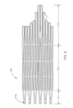
内側フレーム250が、図6~図8に更に詳細に示されている。具体的には、図6~図8は、それぞれ、一実施形態による内側フレーム250の未変形の初期状態(図6)、拡開形態にある内側フレーム250の側面図(図7)、および、拡開形態にある内側フレーム250の底面図(図8)を示している。
この実施形態では、内側フレーム250は、ニチノールのレーザカットチューブから形成されている。図6には、未変形の初期状態、すなわち、レーザーカットされたままの状態、しかし、説明を容易にするためにカットされた後平坦なシートに巻き戻された状態にある内側フレーム250が示されている。内側フレーム250は、最終形状の内側フレーム250の機能的に互いに異なる部分に対応する4つの部分、すなわち、心房部分247、本体部分242、ストラット部分243、および、テザー締結部分またはテザー接続部分244に分割されている。ストラット部分243は、本体部分242をテザー接続部分244に接続する6つのストラット、例えば、ストラット243Aを備えている。
In this embodiment, the
(内側フレームの第1の端部分とも呼ばれる)テザー接続部分244は、互いに向き合ったわずかにV字状の接続部材(または「挟角V字状部材」)の対によって周方向において互いに接続されたストラットの長手方向延長部を備えている。テザー接続部分244は、圧縮力の印加によって半径方向に折畳まれるように構成されている。この場合、狭角V字状部分の頂点が長手方向において互いに接近すると共に、V字形状の開端が周方向において互いに接近し、狭角V字状部分がより鋭利な狭角になる。従って、テザー接続部分244は、テザーの一端を圧縮によって締結または把持するように構成されている。具体的には、テザー接続部分244は、圧縮によって、テザーライン(例えば、編組フィラメントライン)に直接接続されるか、またはテザーラインに固着されたポリマーまたは金属片のような中間金属に接続されるようになっている。
The tether connecting portions 244 (also referred to as the inner frame first end portion) are connected together circumferentially by a pair of slightly V-shaped connecting members (or “closed angle V-members”) facing each other. A longitudinal extension of the strut is provided.
テザー接続部分244と対照的に、(「内側フレーム自由端部分」とも呼ばれる)心房部分247および本体部分242は、半径方向に拡開されるように構成されている。ストラット部分243によって、拡開された本体部分と圧縮されたテザー接続部分244との間に長手方向接続/半径方向移行部が形成される。本体部分242は、6つの長手方向ポスト、例えば、ポスト242Aを備える内側フレーム連結部分245を備えている。内側フレーム連結部分245を用いて、弁葉270を内側フレーム240に取り付けることができ、および/または内側フレーム連結部分245を用いて、例えば、内側フレーム250を外側フレーム220に接続することによって、内側アセンブリ240を外側アセンブリ210に取り付けることができる。例示される実施形態では、ポストは、開口を備え、(縫合フィラメントおよび/またはワイヤのような)接続部材をこれらの開口に通すことによって、該ポストを他の構造体に連結することができる。
In contrast to
完全な変形形態、すなわち、最終的展開形態にある内側フレーム250の側面図および底面図が、それぞれ、図7および図8に示されている。
Side and bottom views of
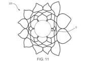
弁200の外側フレーム220が、図9~図11にさらに詳細に示されている。この実施形態では、外側フレーム220もニチノール(Nitinol;登録商標)のレーザーカットチューブから形成されている。図9には、未変形の初期状態、すなわち、レーザーカットされたままの状態、しかし、説明を容易にするためにカットされた後平坦なシートに巻き戻された状態にある外側フレーム220が示されている。外側フレーム220は、図9に示されるように、外側フレーム連結部分271、本体部分272、および(心房部分または自由端部分216を備える)カフ部分273に分割されている。外側フレーム連結部分271は、多数の開口または孔、例えば、開口271Aを備え、これらの開口271Aによって、外側フレーム220は、以下に更に詳細に説明するように、内側フレーム250に連結されることになる。
The
図10および図11は、それぞれ、完全な変形形態、すなわち、最終的な展開形態にある外側フレーム220の側面図および上面図を示している。図11に最もよく示されるように、外側フレーム連結部分271の下端は、(図11において「O」の符号が付された)略円状開口を形成している。この開口の直径は、好ましくは、内側フレーム250の本体部分242の直径に略対応し、これにより、弁200の2つの構成要素の連結が容易になる。
Figures 10 and 11 show side and top views, respectively, of the
図12~図14は、それぞれ、互いに連結された外側フレーム220および内側フレーム250の正面図、側面図、および、上面図を示している。2つのフレームは、連携して、人工弁、例えば、弁200の構造的支持体を形成する。これらのフレームは、弁葉構造(例えば、弁葉270)を生来の弁輪に対して所望の関係を満たすように支持し、また心房と心室との間の血液漏れに対してバリアをもたらすために、2つのフレームのカバー(例えば、外側フレームアセンブリ210の外側カバー230および内側カバー232、および、内側弁アセンブリ240の外側カバー)を支持し、更に心室壁へのテザー接続によって人工弁200を生来の弁輪の適所に保持するのを支援するために、(図3~14に示されない)テザー(例えば、図1,2A,2Bに関して前述したテザー136)を内側フレーム250に連結するようになっている。外側フレーム220および内側フレーム250は、6つの連結点(図12~14において「C」の符号が付された代表点)において互いに接続されている。この実施形態では、これらの連結点は、機械的な固定具、例えば、外側フレーム連結部分271の開口(例えば、開口217A)と内側フレーム250の本体部分242の内側フレーム連結部分245(例えば、ポスト242Aのような長手方向ポスト)の対応する開口とを通る短いワイヤによって形成されている。このようにして、内側フレーム250は、外側フレーム220内に配置され、しっかりと外側フレーム220に連結されることになる。
12-14 show front, side and top views, respectively, of
図15~図21は、人工心臓弁(例えば、人工僧帽弁)300を心臓の心房内に送達するために送達シース326(例えば、図17~図21参照)内に挿入する前に、人工心臓弁300を再構成する方法を示している。(「弁」とも呼ばれる)人工心臓弁300は、前述の弁100,200と同一または同様に構成され、それらの弁100,200と同一または同様に機能することができる。従って、弁300に関する詳細の一部は、以下の説明において省略される。特徴および構成について具体的に説明しないが、これらの特徴および機能は、弁200の特徴および機能と同一または同様であってもよいことを理解されたい。
FIGS. 15-21 illustrate a prosthetic heart valve (eg, mitral valve prosthesis) 300 prior to insertion into a delivery sheath 326 (see, eg, FIGS. 17-21) for delivery into the atria of the heart. A method of reconstructing a
図15に示されるように、弁300は、外側フレーム320および内側フレーム350を有している。弁100,200に対して前述したように、弁300の外側フレーム320および内側フレーム350は、各々、形状記憶材料によって形成されており、付勢による拡開形態を有している。外側フレーム320および内側フレーム350は、心臓への弁300の送達のための折畳形態に移行させることができる。心臓に送達するために弁300を準備するこの例示的な方法では、弁300の外側フレーム320が、最初、図16に示されるように、逸脱形態または反転形態に配置される。具体的には、弁300の外側フレーム320の弾性または超弾性構造によって、弁300が送達シース326の管腔内に挿入される前に、外側フレーム320を逸脱形態または反転形態に配置させることができる。図16に示されるように、外側フレーム320を反転形態に配置するために、外側フレーム320は、外側フレーム320の開自由端316が内側フレーム350の開自由端347から離れる方に向けられるように、遠位側(図16の右側)に折畳まれるかまたは反転される。弁100に対して前述したように、この反転形態では、弁300の全体的な外周又外径が減少し、全長が増大する。例えば、図15に示される直径D1は、図16に示される直径D2よりも大きく、(弁200に対して図12に示される)長さL1は、弁300に対する図16に示される長さL2よりも短い。外側フレーム320が内側フレーム350に対して反転形態にあるので、図17に示されるように、弁300を(心臓の左心房に送達するための)送達シース326の管腔内に配置することができる。外側フレーム320を内側フレーム350に対して反転形態に配置することによって、図15に示される形態にある弁300が反転されずに半径方向に折畳まれた時よりも、弁300をより小さい直径に折畳むことができ、すなわち、より小さい直径の送達シース内に配置することができる。何故なら、図15に示される形態では、2つのフレームが同心状または入れ子状になっているので、外側フレーム320は、内側フレーム350の周りに折畳まれねばならないが、図16に示される形態では、2つのフレームは、実質的に同軸であるが、同心状または入れ子状になっていないからである。従って、図16に示される形態では、内側フレーム350を内側に受け入れることなく、外側フレーム320を折畳むことができる。換言すれば、内側フレーム350の殆どが外側フレーム320内に配置され、すなわち、入れ子になっている場合、フレーム構造のこれらの層、すなわち、フレーム構造の嵩の全体を小さい直径に圧縮することができない。加えて、もしこれらのフレームが入れ子になっていたなら、フレーム構造は、柔軟性に欠け、その結果、例えば、曲がりくねった血管系を通るための弁の屈曲に対してより大きな力が必要になり、または僧帽弁輪内への挿入に対して適切に配向させるために心房中隔を通った後に左心房内において急転回させるための弁の屈曲に対してより大きな力が必要になる。
As shown in FIG. 15,
図22~図24は、弁300を心臓に送達する手順の一部を示している。この実施形態では、弁300は、例えば、(参照することによってここに含まれる)‘305PCT出願記載される経大腿送達アプローチによって送達されるものとして示されている。弁300が図17に示されるように反転形態で管腔内に配置されている送達シース326が、大腿突刺孔内に挿入され、大腿静脈および下大静脈を通って、右心房に入り、中隔Spを通って、心臓の左心房LA内に入る。送達シース326の遠位端部分が心臓の左心房内に配置されたなら、弁300が送達シース326の遠位端の外側に展開される。例えば、いくつかの実施形態では、プッシャー装置338を用いて、弁300を送達シース326の遠位端の外に移動させ、すなわち、押し出すことができる。図22~図24に示されるように、テザー336を弁300に取り付け、僧帽弁輪および左心室LVを通って、心尖Apの突刺部位から外に延ばすことができる。いくつかの実施形態では、テザー336を近位側に引っ張ることによって、弁300を送達シース326の外に移動させることができる。いくつかの実施形態では、プッシャー装置によって押し出すと共にテザーによって引っ張ることによって、弁300を展開させることができる。
22-24 illustrate part of the procedure for delivering
弁300が送達シース326の管腔を出る時、外側フレームアセンブリ310は、図18~図20(図22も参照)の進展ステップに示されるように、最初、その反転形態にある。外側フレームアセンブリ310が送達シース326の管腔の外側に完全に出た後、外側フレーム320は、図21,23,24に示されるように、その拡開または展開形態に復元することになる。いくつかの実施形態では、外側フレーム320は、送達シースの管腔を完全に出た後、その形状記憶特性によって自動的に復元することができる。いくつかの実施形態では、外側フレームアセンブリ310の復元を助長させるために、送達シースの構成要素または他の装置が用いられてもよい。いくつかの実施形態では、外側フレームアセンブリ310の復元を助長させるために、プッシャー装置および/またはテザーが用いられてもよい。内側フレーム350が左心房内において完全に展開し、弁300が(例えば、図15および図24に示されるように)拡開または展開形態になるまで、弁300を連続的に展開させることができる。次いで、図24に示されるようにおよび‘572PCT出願および‘305PCT出願に更に詳細に記載されるように、弁300およびテザー336を心外膜パッド装置339によって心房の心尖に固定することができる。
When the
図25Aは、人工心臓弁400の他の実施形態を示している。弁400は、前述の他の人工心臓弁と実質的に同様である。例えば、弁400は、前述の弁100,200と同一または同様に構成され、前述の弁100,200と同一または同様に機能する。弁400は、外側フレームアセンブリ(図示せず)および外側フレームアセンブリに連結された内側弁アセンブリを備えている(内側弁アセンブリの一部が図25A~26に示されている)。内側弁アセンブリは、内側フレーム450を備えている(内側フレームの一部が図25A~26に示されている)。弁400に関する一部の詳細については、以下に説明しない。具体的に説明しない特徴および機能については、これらの特徴および機能は、弁100または弁200の特徴および機能と同一または同様であることを理解されたい。例えば、弁400は、前述の弁葉270のよう弁葉(図示せず)を備えることができる。
FIG. 25A shows another embodiment of a
図25Aは、拡開形態にある弁400の内側フレーム450の一部を示し、図26は、未拡開形態にある内側フレーム450の展開図である。弁100,200に対して前述したように、弁400の内側フレーム450は、形状記憶材料から形成され、付勢による拡開形態を有している。例えば、弁400の内側フレームは、ニチノールのレーザーカットチューブから形成可能である。更に、内側フレーム450は、最終形状の内側フレーム450の機能的に異なる部分に対応する4つの部分、すなわち、心房部分、本体部分、ストラット部分、および、テザー締結部分またはテザー接続部分に分割されている。本体部分442、ストラット部分443、および、テザー締結部分またはテザー接続部分444の一部が図25Aに示されている。
Figure 25A shows a portion of
この実施形態では、ストラット部分443は、例えば、6つのストラット453、具体的には、図25A,25Bに示されるストラット453A,453Bを備えることができる。弁100に対して前述したように、ストラット453は、テザー接続部分444を形成するように延在している。これについては、以下に更に詳細に説明する。また、ストラット部分443は、弁100,200に対して前述したように、開口を備え、(縫合フィラメントおよび/またはワイヤのような)接続部材が該開口に通され、ストラット453(および内側フレーム)を他の構造(例えば、外側フレームアセンブリ)に連結するようになっている。図25A~26は、6つのストラット453(3対のストラット453A,453B)を備えるストラット部分443を示しているが、6つよりも少ないかまたは6つよりも多い数のストラット453を備える他の実施形態も考えられる。
In this embodiment,
この実施形態では、6つのストラット453の内の2つのストラット(すなわち、453A,453B)が一緒にされ、テザー接続部分444のストラット448を形成している。換言すれば、第1のストラット部分453Aおよび第2のストラット部分453Bは、一緒にされ、第3のストラット部分448を形成している。例えば、図25Bに示されるように、2つのストラット453A,453Bが一緒にされ、ストラット448Aを形成している。従って、ストラット部分443の6つのストラット453によって、テザー接続部分444の3つのストラット448が形成される。テザー接続部分444のストラット448は、開口451(例えば、図25A,25B参照)を画定している。これらの開口451を用いて、以下に更に詳細に説明するように、縫合糸によって(図26に示される)テザー436を内側フレーム450に固定することができる。
In this embodiment, two of the six struts 453 (ie, 453A, 453B) are brought together to form
2つ以上のストラット(例えば、ストラット453A,453B)を組み合わせてテザー接続ストラット448を形成することによって、テザー接続ストラット448の壁厚を増大させることができる。例えば、(図25Bに示されるように)開口451び傍らのストラット448の部分の壁厚または幅「w」が(図6の弁200の接続部分244の開口の周りの壁厚と比較した時に)増大され、その結果、もし接続部分444の輪郭/直径が弁200の輪郭/直径と実質的に同じであったなら、組み合わされたテザー接続部分44の引張能力が増大することになる。この増大した引張能力は、テザー接続部分444と内側フレーム450との構造的一体性を高めることができる。いくつかの実施形態では、引張能力が(弁200と比較した時に)維持された場合、接続部分444の輪郭/直径が(弁200と比較した時に)低減される。例えば、図26に示されるように、内側フレーム450は、内側フレーム250に対して説明した「マイクロV字状部材」を備えず、これによって、、輪郭を縮小することができ、または代替的に同一の輪郭を維持する場合、幅「w」を増大させ且つ引張強度を高める能力を増大させることができる。
The wall thickness of
弁100に対して前述したように単一のテザー接続ストラット448を形成するように組み合わされる2つ(またはそれ以上)のストラット(図25A,25Bに示されるストラット453A,453B)は、(図25A,25Bに示されるように)予成形されたままの状態で組み合わされ、次いで、一体に形成されるかまたは融合されてもよいし、またはテザー接続部分444の単一のストラットを形成するために、別の構成部品として形成され、且つ一緒に連結されてもよい。
Two (or more) struts (struts 453A, 453B shown in FIGS. 25A, 25B) that combine to form a single
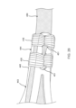
図27~29は、人工弁400の内側フレーム450を示している。内側フレーム450のテザー接続部分44は、(「縫合糸」とも呼ばれる)一本または複数本の縫合ストラット435によって、テザー436の一端に連結されている。具体的には、縫合糸435は、テザー436の端を圧縮によって締付けまたは把持し、これによって、テザー436を内側フレーム450および弁400に取り付けている。例えば、縫合糸435は、接続部分444に画定された開口451に縫い込まれ、テザー接続部分444の一部および接続部分444のストラット453/448によって協働して画定された内部領域456(図25A参照)内に配置されたテザー436の一部の周りに巻き付けられている。
27-29 show the
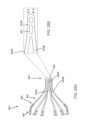
いくつかの実施形態では、人工弁の内側フレームのストラット部分は、人工心臓弁の位置決めを支援する雄型係合部を備えている。更に具体的には、前述したように、人工弁は、位置決め装置、例えば、前述の位置決め装置190の係合部と嵌め合いによって係合するように構成された係合部を備えることができる。心臓弁500の内側フレーム550の他の実施形態が、図30~33に示されている。図30は、拡開形態にある内側フレーム550の(テザー536に端部に連結された)部分を示し、図31は、未拡開形態にある内側フレーム550の展開図を示している。人工心臓弁500は、例えば、前述の弁100,200,400と同一または同様に構成され、これらの弁100,200,400と同一または同様に機能する。例えば、弁500は、外側フレームアセンブリ(図示せず)および外側フレームアセンブリに連結された内側弁アセンブリを備えている。弁500の内側弁アセンブリは、内側フレーム550を備えている。内側フレーム550は、弁100,200,400および内側フレーム150,250,450に対して前述したように、心房部分(図示せず)、本体部分542、ストラット部分543、および、テザー締結部分またはテザー接続部分544を備えている。
In some embodiments, the strut portion of the inner frame of the prosthetic valve includes male mating portions that assist in positioning the prosthetic heart valve. More specifically, as discussed above, the prosthetic valve can comprise an engaging portion configured to matingly engage an engaging portion of a positioning device, eg, the
図30~33に示されるように、弁500の内側フレーム550は、テザー接続部分544において、縫合糸535によってテザー536に連結される。前述したように、ストラット部分543の1対のストラット553が一緒に組合わされまたは収斂され、テザー接続部分544の単一ストラット548を形成する。単一ストラット548は、テザー536を圧縮によって締め付け、該テザー536を内側フレーム550に連結するために用いられる。この実施形態では、内側フレーム550は、テザー接続部分544のストラット548によって設けられた係合部522を備えている。この係合部522は、(図示されない)位置決め装置(例えば、位置決め装置190)の対応する係合部分と嵌め合いによって係合するようになっている。更に具体的には、ストラット548の1つは、保持ストラット548よりも長くなっている(例えば、心臓内に移植された時に近位側により延出する)。この係合部522を用いて、内側フレーム(および弁500)を半径方向に位置決めするために用いられる)位置決め装置(図示せず)の対応する開口に係合させることができる。
As shown in FIGS. 30-33,
前述の位置決め装置は、テザー536が通る管腔を画定しており、心臓の心尖を通って挿入され、遠位側に移動され、係合部522を介して弁500と係合するようになっている。例えば、弁500の展開中、例えば、弁500が心臓の心房内に少なくとも部分的に配置された時、位置決め装置が心臓の心尖を通って挿入され、位置決め装置の遠位端部分が弁500の接続部分544と係合する。係合時に、経心尖位置決め装置を用いて、弁500をテザー536の長軸を中心として旋回または回転させるようにトルクを加えることによって、弁500を心臓内において半径方向に位置決めすることができる。
The aforementioned positioning device, defining a lumen through which
図30~33は、テザー接続部分544の1つのストラット548が長くなって係合部522をもたらす一実施形態を示しているが、2つ以上のストラット548が係合部522をもたらすかまたは形成する他の実施形態も考えられる。更に、図30~33は、1つのより長いストラット548によって形成される係合部522を示しているが、2つ以上のストラットがテザー接続部分544において短くなっており、これらのストラットが長孔または開口を形成することによって得られる係合部を備える他の実施形態も考えられる。このような開口が該開口と嵌合する細長構造または突起の形態にある対係合部を有する位置決め装置に連結されることになる。
30-33 show an embodiment in which one
種々の実施形態について説明してきたが、これらの実施形態は、単なる例示にすぎず、制限するものではないことを理解されたい。前述の方法は、ある特定の順序で生じるいくつかの事象を示しているが、このようないくつかの事象の順序は、変更されてもよい。加えて、これらの事象のいくつかは、可能であれば、並列プロセスによって同時に行われてもよいし、前述したように連続的に行われてもよい。 While various embodiments have been described, it is to be understood that these embodiments are illustrative only and not limiting. Although the methods described above show certain events occurring in a particular order, the order of certain such events may be changed. Additionally, some of these events may be performed concurrently by parallel processes where possible, or may be performed serially as previously described.
前述の図表および/または実施形態は、いくつかの方位または位置に配置されたいくつかの構成を示しているが、これらの構成要素の配置は、変更されてもよい。実施形態を具体的に図示し且つ説明してきたが、形態および細部の種々の変更がなされてもよいことを理解されたい。本明細書に記載される装置および/または方法のどのような部分であっても、相互に排他的な組み合わせを除けば、任意に組み合わされてもよい。本明細書に記載される実施形態は、本明細書に記載される機能、構成要素、および/または特徴の種々の組合せおよび/または副次的な組み合わせを含むことができる。 Although the diagrams and/or embodiments described above show some configurations arranged in certain orientations or locations, the arrangement of these components may be changed. Although the embodiments have been particularly illustrated and described, it is to be understood that various changes in form and detail may be made. Any portion of the apparatus and/or methods described herein may be combined in any, except mutually exclusive combinations. Embodiments described herein can include various combinations and/or subcombinations of the features, components, and/or features described herein.
加えて、本明細書に記載されるシステムおよび方法は、人工三尖弁の使用にも適用可能である。例えば、このような場合、処置カテーテルは、心臓の右心室に挿入され、送達シースは、直接的に(経心尖的に)または頸静脈または大腿静脈を介して、心臓の右心房に送達されることになる。 Additionally, the systems and methods described herein are applicable for use with a prosthetic tricuspid valve. For example, in such cases, the treatment catheter is inserted into the right ventricle of the heart and the delivery sheath is delivered to the right atrium of the heart either directly (transapically) or via the jugular or femoral veins. It will be.
Claims (14)
外側フレームと、
前記外側フレームに連結され、前記人工心臓弁の近位端部分に配置されたテザー連結部分を備える、内側フレームと、
少なくとも1本の縫合糸によって前記内側フレームの前記テザー連結部分に連結され、患者の心臓内における前記人工心臓弁の位置を固定するために、前記患者の前記心臓の壁に固定されるように構成されている、係留テザーと、
を備え、
前記テザー連結部分は、位置決め装置の第2の係合部に嵌め合いによって離脱可能に係合するように構成された第1の係合部を備え、前記位置決め装置は、前記人工心臓弁を前記患者の前記心臓内に位置決めするのを支援するように構成され、
前記内側フレームの前記テザー連結部分は、複数のストラットを備え、前記第1の係合部は、前記複数のストラットのうちの残余のストラットよりも長い第1のストラットを含み、前記第1のストラットは、前記内側フレームを前記位置決め装置に離脱可能に連結するために前記位置決め装置に画定された開口内に嵌め合いによって受け入れられるように構成されている、人工心臓弁。 A prosthetic heart valve,
an outer frame;
an inner frame connected to the outer frame and comprising a tether connection portion positioned at a proximal end portion of the prosthetic heart valve;
coupled to the tethered portion of the inner frame by at least one suture and configured to be secured to the wall of the heart of the patient to fix the position of the prosthetic heart valve within the patient's heart; a tethered tether and
with
The tether connecting portion comprises a first engaging portion configured to releasably engage a second engaging portion of a positioning device by way of a fit, the positioning device connecting the prosthetic heart valve to the configured to assist in positioning within said heart of a patient;
The tether connecting portion of the inner frame comprises a plurality of struts, the first engagement portion including a first strut that is longer than the remaining struts of the plurality of struts, and the first strut. is configured to be matingly received within an opening defined in the positioning device to detachably couple the inner frame to the positioning device.
前記内側フレームは、前記人工心臓弁の近位端部分に配置されたテザー連結部分を備え、前記係留テザーは、少なくとも1本の縫合糸によって前記内側フレームの前記テザー連結部分に連結され,前記係留テザーは、患者の心臓内における前記人工心臓弁の位置を固定するために、前記患者の前記心臓の壁に固定されるように構成されている、人工心臓弁と、
前記内側フレームの前記テザー連結部分に係合するように構成され、前記人工心臓弁を前記患者の前記心臓内に位置決めするのを支援するために用いられる位置決め装置と、を備え、
前記テザー連結部分は、位置決め装置の第2の係合部に嵌め合いによって連結されるように連結される第1の係合部を備え、
前記内側フレームの前記テザー連結部分は、複数のストラットを備え、前記第1の係合部は、前記複数のストラットのうちの残余のストラットよりも長い第1のストラットを含み、前記第1のストラットは、前記内側フレームを前記位置決め装置に離脱可能に連結するために前記位置決め装置に画定された長孔内に嵌め合いによって受け入れられるように構成されている、キット。 A heart valve prosthesis comprising an outer frame, an inner frame coupled to the outer frame, and an anchoring tether coupled to the inner frame, comprising:
The inner frame includes a tether connection portion positioned at a proximal end portion of the heart valve prosthesis, the anchoring tether connected to the tether connection portion of the inner frame by at least one suture, the anchoring a prosthetic heart valve configured to be secured to a wall of the patient's heart to fix the position of the prosthetic heart valve within the patient's heart;
a positioning device configured to engage the tethered portion of the inner frame and used to assist in positioning the prosthetic heart valve within the heart of the patient;
the tether connecting portion comprises a first engaging portion that is connected to a second engaging portion of the positioning device in a form-fitting manner;
The tether connecting portion of the inner frame comprises a plurality of struts, the first engagement portion including a first strut that is longer than the remaining struts of the plurality of struts, and the first strut. is configured to be matingly received within a slot defined in said positioning device for detachably coupling said inner frame to said positioning device.
Applications Claiming Priority (3)
| Application Number | Priority Date | Filing Date | Title |
|---|---|---|---|
| US201762550967P | 2017-08-28 | 2017-08-28 | |
| US62/550,967 | 2017-08-28 | ||
| PCT/US2018/047768 WO2019046099A1 (en) | 2017-08-28 | 2018-08-23 | Prosthetic heart valves with tether coupling features |
Publications (3)
| Publication Number | Publication Date |
|---|---|
| JP2020531178A JP2020531178A (en) | 2020-11-05 |
| JP2020531178A5 JP2020531178A5 (en) | 2021-09-30 |
| JP7291124B2 true JP7291124B2 (en) | 2023-06-14 |
Family
ID=63452769
Family Applications (1)
| Application Number | Title | Priority Date | Filing Date |
|---|---|---|---|
| JP2020511752A Active JP7291124B2 (en) | 2017-08-28 | 2018-08-23 | Heart valve prosthesis with tethered connections |
Country Status (6)
| Country | Link |
|---|---|
| US (1) | US11191639B2 (en) |
| EP (1) | EP3675774B1 (en) |
| JP (1) | JP7291124B2 (en) |
| CN (1) | CN111031967B (en) |
| AU (1) | AU2018323900A1 (en) |
| WO (1) | WO2019046099A1 (en) |
Families Citing this family (18)
| Publication number | Priority date | Publication date | Assignee | Title |
|---|---|---|---|---|
| WO2019195860A2 (en) | 2018-04-04 | 2019-10-10 | Vdyne, Llc | Devices and methods for anchoring transcatheter heart valve |
| US11344413B2 (en) | 2018-09-20 | 2022-05-31 | Vdyne, Inc. | Transcatheter deliverable prosthetic heart valves and methods of delivery |
| US11071627B2 (en) | 2018-10-18 | 2021-07-27 | Vdyne, Inc. | Orthogonally delivered transcatheter heart valve frame for valve in valve prosthesis |
| US10595994B1 (en) | 2018-09-20 | 2020-03-24 | Vdyne, Llc | Side-delivered transcatheter heart valve replacement |
| US10321995B1 (en) | 2018-09-20 | 2019-06-18 | Vdyne, Llc | Orthogonally delivered transcatheter heart valve replacement |
| US11278437B2 (en) | 2018-12-08 | 2022-03-22 | Vdyne, Inc. | Compression capable annular frames for side delivery of transcatheter heart valve replacement |
| US11109969B2 (en) | 2018-10-22 | 2021-09-07 | Vdyne, Inc. | Guidewire delivery of transcatheter heart valve |
| US11253359B2 (en) | 2018-12-20 | 2022-02-22 | Vdyne, Inc. | Proximal tab for side-delivered transcatheter heart valves and methods of delivery |
| US11273032B2 (en) | 2019-01-26 | 2022-03-15 | Vdyne, Inc. | Collapsible inner flow control component for side-deliverable transcatheter heart valve prosthesis |
| US11185409B2 (en) | 2019-01-26 | 2021-11-30 | Vdyne, Inc. | Collapsible inner flow control component for side-delivered transcatheter heart valve prosthesis |
| CN113543750A (en) | 2019-03-05 | 2021-10-22 | 维迪内股份有限公司 | Tricuspid valve regurgitation control apparatus for orthogonal transcatheter heart valve prosthesis |
| US11076956B2 (en) | 2019-03-14 | 2021-08-03 | Vdyne, Inc. | Proximal, distal, and anterior anchoring tabs for side-delivered transcatheter mitral valve prosthesis |
| US11173027B2 (en) | 2019-03-14 | 2021-11-16 | Vdyne, Inc. | Side-deliverable transcatheter prosthetic valves and methods for delivering and anchoring the same |
| AU2020267390A1 (en) | 2019-05-04 | 2021-11-11 | Vdyne, Inc. | Cinch device and method for deployment of a side-delivered prosthetic heart valve in a native annulus |
| JP2022544707A (en) | 2019-08-20 | 2022-10-20 | ブイダイン,インコーポレイテッド | Devices and methods for delivery and retrieval of laterally deliverable transcatheter valve prostheses |
| WO2021040996A1 (en) | 2019-08-26 | 2021-03-04 | Vdyne, Inc. | Side-deliverable transcatheter prosthetic valves and methods for delivering and anchoring the same |
| US11234813B2 (en) | 2020-01-17 | 2022-02-01 | Vdyne, Inc. | Ventricular stability elements for side-deliverable prosthetic heart valves and methods of delivery |
| WO2022039853A1 (en) * | 2020-08-19 | 2022-02-24 | Tendyne Holdings, Inc. | Fully-transseptal apical pad with pulley for tensioning |
Citations (4)
| Publication number | Priority date | Publication date | Assignee | Title |
|---|---|---|---|---|
| JP2016520391A (en) | 2013-05-30 | 2016-07-14 | テンダイン ホールディングス,インコーポレイテッド | Structural member for prosthetic mitral valve |
| JP2016533787A (en) | 2013-10-28 | 2016-11-04 | テンダイン ホールディングス,インコーポレイテッド | Prosthetic heart valve and system and method for delivering an artificial heart valve |
| WO2016196933A1 (en) | 2015-06-05 | 2016-12-08 | Tendyne Holdings, Inc. | Apical control of transvascular delivery of prosthetic mitral valve |
| US20170079790A1 (en) | 2015-09-18 | 2017-03-23 | Tendyne Holdings, Inc. | Apparatus and methods for delivery of prosthetic mitral valve |
Family Cites Families (660)
| Publication number | Priority date | Publication date | Assignee | Title |
|---|---|---|---|---|
| US2697008A (en) | 1953-10-09 | 1954-12-14 | Globe Automatic Sprinkler Co | Sprinkler head |
| GB1127325A (en) | 1965-08-23 | 1968-09-18 | Henry Berry | Improved instrument for inserting artificial heart valves |
| US3587115A (en) | 1966-05-04 | 1971-06-28 | Donald P Shiley | Prosthetic sutureless heart valves and implant tools therefor |
| US3472230A (en) | 1966-12-19 | 1969-10-14 | Fogarty T J | Umbrella catheter |
| US3548417A (en) | 1967-09-05 | 1970-12-22 | Ronnie G Kischer | Heart valve having a flexible wall which rotates between open and closed positions |
| US3476101A (en) | 1967-12-28 | 1969-11-04 | Texas Instruments Inc | Gas-fired oven |
| US3671979A (en) | 1969-09-23 | 1972-06-27 | Univ Utah | Catheter mounted artificial heart valve for implanting in close proximity to a defective natural heart valve |
| US3657744A (en) | 1970-05-08 | 1972-04-25 | Univ Minnesota | Method for fixing prosthetic implants in a living body |
| US3714671A (en) | 1970-11-30 | 1973-02-06 | Cutter Lab | Tissue-type heart valve with a graft support ring or stent |
| US3755823A (en) | 1971-04-23 | 1973-09-04 | Hancock Laboratories Inc | Flexible stent for heart valve |
| GB1402255A (en) | 1971-09-24 | 1975-08-06 | Smiths Industries Ltd | Medical or surgical devices of the kind having an inflatable balloon |
| US3976079A (en) | 1974-08-01 | 1976-08-24 | Samuels Peter B | Securing devices for sutures |
| US4003382A (en) | 1975-07-25 | 1977-01-18 | Ethicon, Inc. | Retention catheter and method of manufacture |
| US4035849A (en) | 1975-11-17 | 1977-07-19 | William W. Angell | Heart valve stent and process for preparing a stented heart valve prosthesis |
| CA1069652A (en) | 1976-01-09 | 1980-01-15 | Alain F. Carpentier | Supported bioprosthetic heart valve with compliant orifice ring |
| US4073438A (en) | 1976-09-03 | 1978-02-14 | Nelson Irrigation Corporation | Sprinkler head |
| US4056854A (en) | 1976-09-28 | 1977-11-08 | The United States Of America As Represented By The Department Of Health, Education And Welfare | Aortic heart valve catheter |
| US4297749A (en) | 1977-04-25 | 1981-11-03 | Albany International Corp. | Heart valve prosthesis |
| US4222126A (en) | 1978-12-14 | 1980-09-16 | The United States Of America As Represented By The Secretary Of The Department Of Health, Education & Welfare | Unitized three leaflet heart valve |
| US4265694A (en) | 1978-12-14 | 1981-05-05 | The United States Of America As Represented By The Department Of Health, Education And Welfare | Method of making unitized three leaflet heart valve |
| US4574803A (en) | 1979-01-19 | 1986-03-11 | Karl Storz | Tissue cutter |
| GB2056023B (en) | 1979-08-06 | 1983-08-10 | Ross D N Bodnar E | Stent for a cardiac valve |
| US4373216A (en) | 1980-10-27 | 1983-02-15 | Hemex, Inc. | Heart valves having edge-guided occluders |
| US4339831A (en) | 1981-03-27 | 1982-07-20 | Medtronic, Inc. | Dynamic annulus heart valve and reconstruction ring |
| US4470157A (en) | 1981-04-27 | 1984-09-11 | Love Jack W | Tricuspid prosthetic tissue heart valve |
| US4345340A (en) | 1981-05-07 | 1982-08-24 | Vascor, Inc. | Stent for mitral/tricuspid heart valve |
| US4406022A (en) | 1981-11-16 | 1983-09-27 | Kathryn Roy | Prosthetic valve means for cardiovascular surgery |
| EP0084395B1 (en) | 1982-01-20 | 1986-08-13 | Martin Morris Black | Artificial heart valves |
| SE445884B (en) | 1982-04-30 | 1986-07-28 | Medinvent Sa | DEVICE FOR IMPLANTATION OF A RODFORM PROTECTION |
| IT1212547B (en) | 1982-08-09 | 1989-11-30 | Iorio Domenico | INSTRUMENT FOR SURGICAL USE INTENDED TO MAKE INTERVENTIONS FOR THE IMPLANTATION OF BIOPROTESIS IN HUMAN ORGANS EASIER AND SAFER |
| GB8300636D0 (en) | 1983-01-11 | 1983-02-09 | Black M M | Heart valve replacements |
| US4535483A (en) | 1983-01-17 | 1985-08-20 | Hemex, Inc. | Suture rings for heart valves |
| US4612011A (en) | 1983-07-22 | 1986-09-16 | Hans Kautzky | Central occluder semi-biological heart valve |
| US4626255A (en) | 1983-09-23 | 1986-12-02 | Christian Weinhold | Heart valve bioprothesis |
| US4585705A (en) | 1983-11-09 | 1986-04-29 | Dow Corning Corporation | Hard organopolysiloxane release coating |
| US4787899A (en) | 1983-12-09 | 1988-11-29 | Lazarus Harrison M | Intraluminal graft device, system and method |
| US4627436A (en) | 1984-03-01 | 1986-12-09 | Innoventions Biomedical Inc. | Angioplasty catheter and method for use thereof |
| US4592340A (en) | 1984-05-02 | 1986-06-03 | Boyles Paul W | Artificial catheter means |
| US5007896A (en) | 1988-12-19 | 1991-04-16 | Surgical Systems & Instruments, Inc. | Rotary-catheter for atherectomy |
| US4979939A (en) | 1984-05-14 | 1990-12-25 | Surgical Systems & Instruments, Inc. | Atherectomy system with a guide wire |
| US4883458A (en) | 1987-02-24 | 1989-11-28 | Surgical Systems & Instruments, Inc. | Atherectomy system and method of using the same |
| DE3426300A1 (en) | 1984-07-17 | 1986-01-30 | Doguhan Dr.med. 6000 Frankfurt Baykut | TWO-WAY VALVE AND ITS USE AS A HEART VALVE PROSTHESIS |
| DE3442088A1 (en) | 1984-11-17 | 1986-05-28 | Beiersdorf Ag, 2000 Hamburg | HEART VALVE PROSTHESIS |
| SU1271508A1 (en) | 1984-11-29 | 1986-11-23 | Горьковский государственный медицинский институт им.С.М.Кирова | Artificial heart valve |
| US4759758A (en) | 1984-12-07 | 1988-07-26 | Shlomo Gabbay | Prosthetic heart valve |
| US4638886A (en) | 1985-10-21 | 1987-01-27 | Sta-Rite Industries, Inc. | Apparatus for disabling an obstructed lift mechanism |
| US4733665C2 (en) | 1985-11-07 | 2002-01-29 | Expandable Grafts Partnership | Expandable intraluminal graft and method and apparatus for implanting an expandable intraluminal graft |
| DE3640745A1 (en) | 1985-11-30 | 1987-06-04 | Ernst Peter Prof Dr M Strecker | Catheter for producing or extending connections to or between body cavities |
| CH672247A5 (en) | 1986-03-06 | 1989-11-15 | Mo Vysshee Tekhnicheskoe Uchil | |
| US4878906A (en) | 1986-03-25 | 1989-11-07 | Servetus Partnership | Endoprosthesis for repairing a damaged vessel |
| US4777951A (en) | 1986-09-19 | 1988-10-18 | Mansfield Scientific, Inc. | Procedure and catheter instrument for treating patients for aortic stenosis |
| US4762128A (en) | 1986-12-09 | 1988-08-09 | Advanced Surgical Intervention, Inc. | Method and apparatus for treating hypertrophy of the prostate gland |
| FR2611628B1 (en) | 1987-02-26 | 1990-11-30 | Bendix France | BRAKE CORRECTOR SERVO-LOADED BY A VEHICLE |
| US4878495A (en) | 1987-05-15 | 1989-11-07 | Joseph Grayzel | Valvuloplasty device with satellite expansion means |
| US4796629A (en) | 1987-06-03 | 1989-01-10 | Joseph Grayzel | Stiffened dilation balloon catheter device |
| US4829990A (en) | 1987-06-25 | 1989-05-16 | Thueroff Joachim | Implantable hydraulic penile erector |
| US4851001A (en) | 1987-09-17 | 1989-07-25 | Taheri Syde A | Prosthetic valve for a blood vein and an associated method of implantation of the valve |
| JPH0624755Y2 (en) | 1987-10-19 | 1994-06-29 | 日産自動車株式会社 | Washer pressure sensor |
| US5266073A (en) | 1987-12-08 | 1993-11-30 | Wall W Henry | Angioplasty stent |
| US4830117A (en) | 1987-12-24 | 1989-05-16 | Fire Sprinkler Specialties, Inc. | Shut-off device for an automatic sprinkler |
| US4960424A (en) | 1988-06-30 | 1990-10-02 | Grooters Ronald K | Method of replacing a defective atrio-ventricular valve with a total atrio-ventricular valve bioprosthesis |
| US5032128A (en) | 1988-07-07 | 1991-07-16 | Medtronic, Inc. | Heart valve prosthesis |
| DE8815082U1 (en) | 1988-11-29 | 1989-05-18 | Biotronik Mess- Und Therapiegeraete Gmbh & Co Ingenieurbuero Berlin, 1000 Berlin, De | |
| US4856516A (en) | 1989-01-09 | 1989-08-15 | Cordis Corporation | Endovascular stent apparatus and method |
| US4966604A (en) | 1989-01-23 | 1990-10-30 | Interventional Technologies Inc. | Expandable atherectomy cutter with flexibly bowed blades |
| US4994077A (en) | 1989-04-21 | 1991-02-19 | Dobben Richard L | Artificial heart valve for implantation in a blood vessel |
| WO1990014804A1 (en) | 1989-05-31 | 1990-12-13 | Baxter International Inc. | Biological valvular prosthesis |
| US5609626A (en) | 1989-05-31 | 1997-03-11 | Baxter International Inc. | Stent devices and support/restrictor assemblies for use in conjunction with prosthetic vascular grafts |
| US4923013A (en) | 1989-08-14 | 1990-05-08 | Gennaro Sergio K De | Fire sprinkler system and automatic shut-off valve therefor |
| US5047041A (en) | 1989-08-22 | 1991-09-10 | Samuels Peter B | Surgical apparatus for the excision of vein valves in situ |
| US4986830A (en) | 1989-09-22 | 1991-01-22 | Schneider (U.S.A.) Inc. | Valvuloplasty catheter with balloon which remains stable during inflation |
| US5035706A (en) | 1989-10-17 | 1991-07-30 | Cook Incorporated | Percutaneous stent and method for retrieval thereof |
| US5089015A (en) | 1989-11-28 | 1992-02-18 | Promedica International | Method for implanting unstented xenografts and allografts |
| US5591185A (en) | 1989-12-14 | 1997-01-07 | Corneal Contouring Development L.L.C. | Method and apparatus for reprofiling or smoothing the anterior or stromal cornea by scraping |
| US5037434A (en) | 1990-04-11 | 1991-08-06 | Carbomedics, Inc. | Bioprosthetic heart valve with elastic commissures |
| US5059177A (en) | 1990-04-19 | 1991-10-22 | Cordis Corporation | Triple lumen balloon catheter |
| DK124690D0 (en) | 1990-05-18 | 1990-05-18 | Henning Rud Andersen | FAT PROTECTION FOR IMPLEMENTATION IN THE BODY FOR REPLACEMENT OF NATURAL FLEET AND CATS FOR USE IN IMPLEMENTING A SUCH FAT PROTECTION |
| US5411552A (en) | 1990-05-18 | 1995-05-02 | Andersen; Henning R. | Valve prothesis for implantation in the body and a catheter for implanting such valve prothesis |
| US5085635A (en) | 1990-05-18 | 1992-02-04 | Cragg Andrew H | Valved-tip angiographic catheter |
| GB9012716D0 (en) | 1990-06-07 | 1990-08-01 | Frater Robert W M | Mitral heart valve replacements |
| US5064435A (en) | 1990-06-28 | 1991-11-12 | Schneider (Usa) Inc. | Self-expanding prosthesis having stable axial length |
| US5336616A (en) | 1990-09-12 | 1994-08-09 | Lifecell Corporation | Method for processing and preserving collagen-based tissues for transplantation |
| US5152771A (en) | 1990-12-31 | 1992-10-06 | The Board Of Supervisors Of Louisiana State University | Valve cutter for arterial by-pass surgery |
| US5282847A (en) | 1991-02-28 | 1994-02-01 | Medtronic, Inc. | Prosthetic vascular grafts with a pleated structure |
| JPH05184611A (en) | 1991-03-19 | 1993-07-27 | Kenji Kusuhara | Valvular annulation retaining member and its attaching method |
| US5295958A (en) | 1991-04-04 | 1994-03-22 | Shturman Cardiology Systems, Inc. | Method and apparatus for in vivo heart valve decalcification |
| US5167628A (en) | 1991-05-02 | 1992-12-01 | Boyles Paul W | Aortic balloon catheter assembly for indirect infusion of the coronary arteries |
| US5397351A (en) | 1991-05-13 | 1995-03-14 | Pavcnik; Dusan | Prosthetic valve for percutaneous insertion |
| ES2159508T3 (en) | 1991-05-16 | 2001-10-16 | Mures Cardiovascular Res Inc | CARDIAC VALVE. |
| US5584803A (en) | 1991-07-16 | 1996-12-17 | Heartport, Inc. | System for cardiac procedures |
| US5769812A (en) | 1991-07-16 | 1998-06-23 | Heartport, Inc. | System for cardiac procedures |
| US5370685A (en) | 1991-07-16 | 1994-12-06 | Stanford Surgical Technologies, Inc. | Endovascular aortic valve replacement |
| US5192297A (en) | 1991-12-31 | 1993-03-09 | Medtronic, Inc. | Apparatus and method for placement and implantation of a stent |
| US5756476A (en) | 1992-01-14 | 1998-05-26 | The United States Of America As Represented By The Department Of Health And Human Services | Inhibition of cell proliferation using antisense oligonucleotides |
| US5201880A (en) | 1992-01-27 | 1993-04-13 | Pioneering Technologies, Inc. | Mitral and tricuspid annuloplasty rings |
| US5306296A (en) | 1992-08-21 | 1994-04-26 | Medtronic, Inc. | Annuloplasty and suture rings |
| JP2002509448A (en) | 1992-01-27 | 2002-03-26 | メドトロニック インコーポレーテッド | Annular forming and suturing rings |
| US5163953A (en) | 1992-02-10 | 1992-11-17 | Vince Dennis J | Toroidal artificial heart valve stent |
| US5683448A (en) | 1992-02-21 | 1997-11-04 | Boston Scientific Technology, Inc. | Intraluminal stent and graft |
| US5332402A (en) | 1992-05-12 | 1994-07-26 | Teitelbaum George P | Percutaneously-inserted cardiac valve |
| DE4327825C2 (en) | 1992-11-24 | 1996-10-02 | Mannesmann Ag | Throttle check element |
| US5797960A (en) | 1993-02-22 | 1998-08-25 | Stevens; John H. | Method and apparatus for thoracoscopic intracardiac procedures |
| US5972030A (en) | 1993-02-22 | 1999-10-26 | Heartport, Inc. | Less-invasive devices and methods for treatment of cardiac valves |
| US5728151A (en) | 1993-02-22 | 1998-03-17 | Heartport, Inc. | Intercostal access devices for less-invasive cardiovascular surgery |
| GB9312666D0 (en) | 1993-06-18 | 1993-08-04 | Vesely Ivan | Bioprostetic heart valve |
| US5607462A (en) | 1993-09-24 | 1997-03-04 | Cardiac Pathways Corporation | Catheter assembly, catheter and multi-catheter introducer for use therewith |
| US5545209A (en) | 1993-09-30 | 1996-08-13 | Texas Petrodet, Inc. | Controlled deployment of a medical device |
| US5480424A (en) | 1993-11-01 | 1996-01-02 | Cox; James L. | Heart valve replacement using flexible tubes |
| US5609627A (en) | 1994-02-09 | 1997-03-11 | Boston Scientific Technology, Inc. | Method for delivering a bifurcated endoluminal prosthesis |
| US5364407A (en) | 1994-03-21 | 1994-11-15 | Poll Wayne L | Laparoscopic suturing system |
| US5728068A (en) | 1994-06-14 | 1998-03-17 | Cordis Corporation | Multi-purpose balloon catheter |
| US5554185A (en) | 1994-07-18 | 1996-09-10 | Block; Peter C. | Inflatable prosthetic cardiovascular valve for percutaneous transluminal implantation of same |
| US5554184A (en) | 1994-07-27 | 1996-09-10 | Machiraju; Venkat R. | Heart valve |
| US5833673A (en) | 1994-11-02 | 1998-11-10 | Daig Corporation | Guiding introducer system for use in the treatment of left ventricular tachycardia |
| US5904697A (en) | 1995-02-24 | 1999-05-18 | Heartport, Inc. | Devices and methods for performing a vascular anastomosis |
| US5683449A (en) | 1995-02-24 | 1997-11-04 | Marcade; Jean Paul | Modular bifurcated intraluminal grafts and methods for delivering and assembling same |
| BE1009278A3 (en) | 1995-04-12 | 1997-01-07 | Corvita Europ | Guardian self-expandable medical device introduced in cavite body, and medical device with a stake as. |
| US5639274A (en) | 1995-06-02 | 1997-06-17 | Fischell; Robert E. | Integrated catheter system for balloon angioplasty and stent delivery |
| US5571175A (en) | 1995-06-07 | 1996-11-05 | St. Jude Medical, Inc. | Suture guard for prosthetic heart valve |
| US5716417A (en) | 1995-06-07 | 1998-02-10 | St. Jude Medical, Inc. | Integral supporting structure for bioprosthetic heart valve |
| US5697905A (en) | 1995-06-19 | 1997-12-16 | Leo T. d'Ambrosio | Triple-lumen intra-aortic catheter |
| US5882341A (en) | 1995-07-07 | 1999-03-16 | Bousquet; Gerald G. | Method of providing a long-lived window through the skin to subcutaneous tissue |
| DE19532846A1 (en) | 1995-09-06 | 1997-03-13 | Georg Dr Berg | Valve for use in heart |
| US5735842A (en) | 1995-09-11 | 1998-04-07 | St. Jude Medical, Inc. | Low profile manipulators for heart valve prostheses |
| US5662704A (en) | 1995-12-01 | 1997-09-02 | Medtronic, Inc. | Physiologic mitral valve bioprosthesis |
| DE19546692C2 (en) | 1995-12-14 | 2002-11-07 | Hans-Reiner Figulla | Self-expanding heart valve prosthesis for implantation in the human body via a catheter system |
| FR2742994B1 (en) | 1995-12-28 | 1998-04-03 | Sgro Jean-Claude | INTRACORPOREAL LIGHT SURGICAL TREATMENT ASSEMBLY |
| US5855602A (en) | 1996-09-09 | 1999-01-05 | Shelhigh, Inc. | Heart valve prosthesis |
| US5716370A (en) | 1996-02-23 | 1998-02-10 | Williamson, Iv; Warren | Means for replacing a heart valve in a minimally invasive manner |
| US6402780B2 (en) | 1996-02-23 | 2002-06-11 | Cardiovascular Technologies, L.L.C. | Means and method of replacing a heart valve in a minimally invasive manner |
| DE69719237T2 (en) | 1996-05-23 | 2003-11-27 | Samsung Electronics Co Ltd | Flexible, self-expandable stent and method for its manufacture |
| US5855601A (en) | 1996-06-21 | 1999-01-05 | The Trustees Of Columbia University In The City Of New York | Artificial heart valve and method and device for implanting the same |
| US5792179A (en) | 1996-07-16 | 1998-08-11 | Sideris; Eleftherios B. | Retrievable cardiac balloon placement |
| US6217585B1 (en) | 1996-08-16 | 2001-04-17 | Converge Medical, Inc. | Mechanical stent and graft delivery system |
| AU739710B2 (en) | 1996-08-23 | 2001-10-18 | Boston Scientific Limited | Stent delivery system having stent securement apparatus |
| US5968068A (en) | 1996-09-12 | 1999-10-19 | Baxter International Inc. | Endovascular delivery system |
| US5968052A (en) | 1996-11-27 | 1999-10-19 | Scimed Life Systems Inc. | Pull back stent delivery system with pistol grip retraction handle |
| US5749890A (en) | 1996-12-03 | 1998-05-12 | Shaknovich; Alexander | Method and system for stent placement in ostial lesions |
| NL1004827C2 (en) | 1996-12-18 | 1998-06-19 | Surgical Innovations Vof | Device for regulating blood circulation. |
| EP0850607A1 (en) | 1996-12-31 | 1998-07-01 | Cordis Corporation | Valve prosthesis for implantation in body channels |
| US6406420B1 (en) | 1997-01-02 | 2002-06-18 | Myocor, Inc. | Methods and devices for improving cardiac function in hearts |
| US6183411B1 (en) | 1998-09-21 | 2001-02-06 | Myocor, Inc. | External stress reduction device and method |
| US6045497A (en) | 1997-01-02 | 2000-04-04 | Myocor, Inc. | Heart wall tension reduction apparatus and method |
| US6077214A (en) | 1998-07-29 | 2000-06-20 | Myocor, Inc. | Stress reduction apparatus and method |
| US5906594A (en) | 1997-01-08 | 1999-05-25 | Symbiosis Corporation | Endoscopic infusion needle having dual distal stops |
| GB9701479D0 (en) | 1997-01-24 | 1997-03-12 | Aortech Europ Ltd | Heart valve |
| US5957949A (en) | 1997-05-01 | 1999-09-28 | World Medical Manufacturing Corp. | Percutaneous placement valve stent |
| US6206917B1 (en) | 1997-05-02 | 2001-03-27 | St. Jude Medical, Inc. | Differential treatment of prosthetic devices |
| US5855597A (en) | 1997-05-07 | 1999-01-05 | Iowa-India Investments Co. Limited | Stent valve and stent graft for percutaneous surgery |
| US6245102B1 (en) | 1997-05-07 | 2001-06-12 | Iowa-India Investments Company Ltd. | Stent, stent graft and stent valve |
| US5971983A (en) | 1997-05-09 | 1999-10-26 | The Regents Of The University Of California | Tissue ablation device and method of use |
| US6123725A (en) | 1997-07-11 | 2000-09-26 | A-Med Systems, Inc. | Single port cardiac support apparatus |
| AU9225598A (en) | 1997-09-04 | 1999-03-22 | Endocore, Inc. | Artificial chordae replacement |
| US6468300B1 (en) | 1997-09-23 | 2002-10-22 | Diseno Y Desarrollo Medico, S.A. De C.V. | Stent covered heterologous tissue |
| US5925063A (en) | 1997-09-26 | 1999-07-20 | Khosravi; Farhad | Coiled sheet valve, filter or occlusive device and methods of use |
| US6332893B1 (en) | 1997-12-17 | 2001-12-25 | Myocor, Inc. | Valve to myocardium tension members device and method |
| CA2315211A1 (en) | 1997-12-29 | 1999-07-08 | The Cleveland Clinic Foundation | System for minimally invasive insertion of a bioprosthetic heart valve |
| US6530952B2 (en) | 1997-12-29 | 2003-03-11 | The Cleveland Clinic Foundation | Bioprosthetic cardiovascular valve system |
| EP0935978A1 (en) | 1998-02-16 | 1999-08-18 | Medicorp S.A. | Angioplasty and stent delivery catheter |
| US6540693B2 (en) | 1998-03-03 | 2003-04-01 | Senorx, Inc. | Methods and apparatus for securing medical instruments to desired locations in a patients body |
| US6174327B1 (en) | 1998-02-27 | 2001-01-16 | Scimed Life Systems, Inc. | Stent deployment apparatus and method |
| EP0943300A1 (en) | 1998-03-17 | 1999-09-22 | Medicorp S.A. | Reversible action endoprosthesis delivery device. |
| US7060021B1 (en) | 1998-07-23 | 2006-06-13 | Wilk Patent Development Corporation | Method and device for improving cardiac function |
| EP2111800B1 (en) | 1998-07-29 | 2016-06-15 | Edwards Lifesciences AG | Transventricular implant tools and devices |
| US6260552B1 (en) | 1998-07-29 | 2001-07-17 | Myocor, Inc. | Transventricular implant tools and devices |
| US6334873B1 (en) | 1998-09-28 | 2002-01-01 | Autogenics | Heart valve having tissue retention with anchors and an outer sheath |
| US7128073B1 (en) | 1998-11-06 | 2006-10-31 | Ev3 Endovascular, Inc. | Method and device for left atrial appendage occlusion |
| US6066160A (en) | 1998-11-23 | 2000-05-23 | Quickie Llc | Passive knotless suture terminator for use in minimally invasive surgery and to facilitate standard tissue securing |
| DE19857887B4 (en) | 1998-12-15 | 2005-05-04 | Fraunhofer-Gesellschaft zur Förderung der angewandten Forschung e.V. | Anchoring support for a heart valve prosthesis |
| FR2788217A1 (en) | 1999-01-12 | 2000-07-13 | Brice Letac | PROSTHETIC VALVE IMPLANTABLE BY CATHETERISM, OR SURGICAL |
| US6350277B1 (en) | 1999-01-15 | 2002-02-26 | Scimed Life Systems, Inc. | Stents with temporary retaining bands |
| US6896690B1 (en) | 2000-01-27 | 2005-05-24 | Viacor, Inc. | Cardiac valve procedure methods and devices |
| US6425916B1 (en) | 1999-02-10 | 2002-07-30 | Michi E. Garrison | Methods and devices for implanting cardiac valves |
| DE19907646A1 (en) | 1999-02-23 | 2000-08-24 | Georg Berg | Valve for blood vessels uses flap holders and counterpart holders on stent to latch together in place and all channeled for guide wire. |
| US6210408B1 (en) | 1999-02-24 | 2001-04-03 | Scimed Life Systems, Inc. | Guide wire system for RF recanalization of vascular blockages |
| EP1176913B1 (en) | 1999-04-09 | 2010-10-13 | Evalve, Inc. | Methods and apparatus for cardiac valve repair |
| US6752813B2 (en) | 1999-04-09 | 2004-06-22 | Evalve, Inc. | Methods and devices for capturing and fixing leaflets in valve repair |
| US6231602B1 (en) | 1999-04-16 | 2001-05-15 | Edwards Lifesciences Corporation | Aortic annuloplasty ring |
| US6790229B1 (en) | 1999-05-25 | 2004-09-14 | Eric Berreklouw | Fixing device, in particular for fixing to vascular wall tissue |
| US6287339B1 (en) | 1999-05-27 | 2001-09-11 | Sulzer Carbomedics Inc. | Sutureless heart valve prosthesis |
| EP1057460A1 (en) | 1999-06-01 | 2000-12-06 | Numed, Inc. | Replacement valve assembly and method of implanting same |
| US7416554B2 (en) | 2002-12-11 | 2008-08-26 | Usgi Medical Inc | Apparatus and methods for forming and securing gastrointestinal tissue folds |
| US7192442B2 (en) | 1999-06-30 | 2007-03-20 | Edwards Lifesciences Ag | Method and device for treatment of mitral insufficiency |
| US6312465B1 (en) | 1999-07-23 | 2001-11-06 | Sulzer Carbomedics Inc. | Heart valve prosthesis with a resiliently deformable retaining member |
| US7674222B2 (en) | 1999-08-09 | 2010-03-09 | Cardiokinetix, Inc. | Cardiac device and methods of use thereof |
| US6299637B1 (en) | 1999-08-20 | 2001-10-09 | Samuel M. Shaolian | Transluminally implantable venous valve |
| IT1307268B1 (en) | 1999-09-30 | 2001-10-30 | Sorin Biomedica Cardio Spa | DEVICE FOR HEART VALVE REPAIR OR REPLACEMENT. |
| US6371983B1 (en) | 1999-10-04 | 2002-04-16 | Ernest Lane | Bioprosthetic heart valve |
| US8632590B2 (en) | 1999-10-20 | 2014-01-21 | Anulex Technologies, Inc. | Apparatus and methods for the treatment of the intervertebral disc |
| US6440164B1 (en) | 1999-10-21 | 2002-08-27 | Scimed Life Systems, Inc. | Implantable prosthetic valve |
| US7018406B2 (en) | 1999-11-17 | 2006-03-28 | Corevalve Sa | Prosthetic valve for transluminal delivery |
| FR2800984B1 (en) | 1999-11-17 | 2001-12-14 | Jacques Seguin | DEVICE FOR REPLACING A HEART VALVE PERCUTANEOUSLY |
| FR2815844B1 (en) | 2000-10-31 | 2003-01-17 | Jacques Seguin | TUBULAR SUPPORT FOR THE PERCUTANEOUS POSITIONING OF A REPLACEMENT HEART VALVE |
| DE19955490A1 (en) | 1999-11-18 | 2001-06-13 | Thermamed Gmbh | Medical heating device |
| US7195641B2 (en) | 1999-11-19 | 2007-03-27 | Advanced Bio Prosthetic Surfaces, Ltd. | Valvular prostheses having metal or pseudometallic construction and methods of manufacture |
| US6458153B1 (en) | 1999-12-31 | 2002-10-01 | Abps Venture One, Ltd. | Endoluminal cardiac and venous valve prostheses and methods of manufacture and delivery thereof |
| US8241274B2 (en) | 2000-01-19 | 2012-08-14 | Medtronic, Inc. | Method for guiding a medical device |
| MXPA02007253A (en) | 2000-01-27 | 2003-09-22 | 3F Therapeutics Inc | Prosthetic heart valve. |
| US6989028B2 (en) | 2000-01-31 | 2006-01-24 | Edwards Lifesciences Ag | Medical system and method for remodeling an extravascular tissue structure |
| US6402781B1 (en) | 2000-01-31 | 2002-06-11 | Mitralife | Percutaneous mitral annuloplasty and cardiac reinforcement |
| MXPA02007426A (en) | 2000-01-31 | 2003-10-14 | Cook Biotech Inc | Stent valves and uses of same. |
| US6797002B2 (en) | 2000-02-02 | 2004-09-28 | Paul A. Spence | Heart valve repair apparatus and methods |
| DE60111184T2 (en) | 2000-02-02 | 2005-10-27 | Robert V. Snyders | ARTIFICIAL HEART FLAP |
| DE10007701C2 (en) | 2000-02-19 | 2002-01-31 | Sartorius Gmbh | Display and control unit for a scale |
| DE10010074B4 (en) | 2000-02-28 | 2005-04-14 | Fraunhofer-Gesellschaft zur Förderung der angewandten Forschung e.V. | Device for fastening and anchoring heart valve prostheses |
| DE10010073B4 (en) | 2000-02-28 | 2005-12-22 | Fraunhofer-Gesellschaft zur Förderung der angewandten Forschung e.V. | Anchoring for implantable heart valve prostheses |
| EP1261282B1 (en) | 2000-03-03 | 2013-09-25 | C. R. Bard, Inc. | Endoscopic tissue apposition device with multiple suction ports |
| WO2001067985A1 (en) | 2000-03-10 | 2001-09-20 | Paracor Surgical, Inc. | Expandable cardiac harness for treating congestive heart failure |
| US6537198B1 (en) | 2000-03-21 | 2003-03-25 | Myocor, Inc. | Splint assembly for improving cardiac function in hearts, and method for implanting the splint assembly |
| US6454799B1 (en) | 2000-04-06 | 2002-09-24 | Edwards Lifesciences Corporation | Minimally-invasive heart valves and methods of use |
| US6610088B1 (en) | 2000-05-03 | 2003-08-26 | Shlomo Gabbay | Biologically covered heart valve prosthesis |
| US6951534B2 (en) | 2000-06-13 | 2005-10-04 | Acorn Cardiovascular, Inc. | Cardiac support device |
| US6358277B1 (en) | 2000-06-21 | 2002-03-19 | The International Heart Institute Of Montana Foundation | Atrio-ventricular valvular device |
| GB2365881A (en) | 2000-07-06 | 2002-02-27 | David Paul Aviram | Interlocking structural panel set |
| US20050113798A1 (en) | 2000-07-21 | 2005-05-26 | Slater Charles R. | Methods and apparatus for treating the interior of a blood vessel |
| WO2002022054A1 (en) | 2000-09-12 | 2002-03-21 | Gabbay S | Valvular prosthesis and method of using same |
| US7510572B2 (en) | 2000-09-12 | 2009-03-31 | Shlomo Gabbay | Implantation system for delivery of a heart valve prosthesis |
| US8956407B2 (en) | 2000-09-20 | 2015-02-17 | Mvrx, Inc. | Methods for reshaping a heart valve annulus using a tensioning implant |
| US20080091264A1 (en) | 2002-11-26 | 2008-04-17 | Ample Medical, Inc. | Devices, systems, and methods for reshaping a heart valve annulus, including the use of magnetic tools |
| US6461382B1 (en) | 2000-09-22 | 2002-10-08 | Edwards Lifesciences Corporation | Flexible heart valve having moveable commissures |
| US6602288B1 (en) | 2000-10-05 | 2003-08-05 | Edwards Lifesciences Corporation | Minimally-invasive annuloplasty repair segment delivery template, system and method of use |
| US6723038B1 (en) | 2000-10-06 | 2004-04-20 | Myocor, Inc. | Methods and devices for improving mitral valve function |
| US6616684B1 (en) | 2000-10-06 | 2003-09-09 | Myocor, Inc. | Endovascular splinting devices and methods |
| DE10049815B4 (en) | 2000-10-09 | 2005-10-13 | Universitätsklinikum Freiburg | Device for local ablation of an aortic valve on the human or animal heart |
| DE10049812B4 (en) | 2000-10-09 | 2004-06-03 | Universitätsklinikum Freiburg | Device for filtering out macroscopic particles from the bloodstream during local removal of an aortic valve on the human or animal heart |
| DE10049814B4 (en) | 2000-10-09 | 2006-10-19 | Universitätsklinikum Freiburg | Device for supporting surgical procedures within a vessel, in particular for minimally invasive explantation and implantation of heart valves |
| DE10049813C1 (en) | 2000-10-09 | 2002-04-18 | Universitaetsklinikum Freiburg | Instrument for the local removal of built-up matter at an aortic valve, in a human or animal heart, is a hollow catheter with a cutting unit at the far end within a closure cap for minimum invasion |
| DE60140829D1 (en) | 2000-11-07 | 2010-01-28 | Carag Ag | Device for closing an opening, for example in a wall of a hollow or tubular organ |
| US6482228B1 (en) | 2000-11-14 | 2002-11-19 | Troy R. Norred | Percutaneous aortic valve replacement |
| US6974476B2 (en) | 2003-05-05 | 2005-12-13 | Rex Medical, L.P. | Percutaneous aortic valve |
| JP4328093B2 (en) | 2000-11-21 | 2009-09-09 | レックス メディカル リミテッド パートナーシップ | Percutaneous aortic valve |
| US6976543B1 (en) | 2000-11-22 | 2005-12-20 | Grinnell Corporation | Low pressure, extended coverage, upright fire protection sprinkler |
| US6494909B2 (en) | 2000-12-01 | 2002-12-17 | Prodesco, Inc. | Endovascular valve |
| ATE310470T1 (en) | 2000-12-15 | 2005-12-15 | Angiomed Ag | STENT WITH HEART VALVE |
| US6468660B2 (en) | 2000-12-29 | 2002-10-22 | St. Jude Medical, Inc. | Biocompatible adhesives |
| US6810882B2 (en) | 2001-01-30 | 2004-11-02 | Ev3 Santa Rosa, Inc. | Transluminal mitral annuloplasty |
| NL1017275C2 (en) | 2001-02-02 | 2002-08-05 | Univ Eindhoven Tech | Heart valve prosthesis has through passage with wall at least partly formed by flexible valve components with free outer ends and movable radially for opening and closing through passage |
| US8038708B2 (en) | 2001-02-05 | 2011-10-18 | Cook Medical Technologies Llc | Implantable device with remodelable material and covering material |
| US7326564B2 (en) | 2001-02-20 | 2008-02-05 | St. Jude Medical, Inc. | Flow system for medical device evaluation and production |
| US20020139056A1 (en) | 2001-03-05 | 2002-10-03 | Finnell Lee M. | Fire protection system |
| US6488704B1 (en) | 2001-05-07 | 2002-12-03 | Biomed Solutions, Llc | Implantable particle measuring apparatus |
| US7556646B2 (en) | 2001-09-13 | 2009-07-07 | Edwards Lifesciences Corporation | Methods and apparatuses for deploying minimally-invasive heart valves |
| CA2441886C (en) | 2001-03-23 | 2009-07-21 | Viacor, Incorporated | Method and apparatus for reducing mitral regurgitation |
| US7374571B2 (en) | 2001-03-23 | 2008-05-20 | Edwards Lifesciences Corporation | Rolled minimally-invasive heart valves and methods of manufacture |
| US6733525B2 (en) | 2001-03-23 | 2004-05-11 | Edwards Lifesciences Corporation | Rolled minimally-invasive heart valves and methods of use |
| US6622730B2 (en) | 2001-03-30 | 2003-09-23 | Myocor, Inc. | Device for marking and aligning positions on the heart |
| US20050096498A1 (en) | 2001-04-24 | 2005-05-05 | Houser Russell A. | Sizing and shaping device for treating congestive heart failure |
| US20050113810A1 (en) | 2001-04-24 | 2005-05-26 | Houser Russell A. | Shaping suture for treating congestive heart failure |
| US20050113811A1 (en) | 2001-04-24 | 2005-05-26 | Houser Russell A. | Method and devices for treating ischemic congestive heart failure |
| US6676692B2 (en) | 2001-04-27 | 2004-01-13 | Intek Technology L.L.C. | Apparatus for delivering, repositioning and/or retrieving self-expanding stents |
| US20020188170A1 (en) | 2001-04-27 | 2002-12-12 | Santamore William P. | Prevention of myocardial infarction induced ventricular expansion and remodeling |
| GB0110551D0 (en) | 2001-04-30 | 2001-06-20 | Angiomed Ag | Self-expanding stent delivery service |
| ITMI20011012A1 (en) | 2001-05-17 | 2002-11-17 | Ottavio Alfieri | ANNULAR PROSTHESIS FOR MITRAL VALVE |
| US6936067B2 (en) | 2001-05-17 | 2005-08-30 | St. Jude Medical Inc. | Prosthetic heart valve with slit stent |
| US6575252B2 (en) | 2001-05-29 | 2003-06-10 | Jeffrey Paul Reed | Sprinkler head deactivating tool |
| US20040064014A1 (en) | 2001-05-31 | 2004-04-01 | Melvin David B. | Devices and methods for assisting natural heart function |
| US6926732B2 (en) | 2001-06-01 | 2005-08-09 | Ams Research Corporation | Stent delivery device and method |
| KR100393548B1 (en) | 2001-06-05 | 2003-08-02 | 주식회사 엠아이텍 | Stent |
| FR2826863B1 (en) | 2001-07-04 | 2003-09-26 | Jacques Seguin | ASSEMBLY FOR PLACING A PROSTHETIC VALVE IN A BODY CONDUIT |
| US6648077B2 (en) | 2001-07-12 | 2003-11-18 | Bryan K. Hoffman | Fire extinguishing system |
| FR2828263B1 (en) | 2001-08-03 | 2007-05-11 | Philipp Bonhoeffer | DEVICE FOR IMPLANTATION OF AN IMPLANT AND METHOD FOR IMPLANTATION OF THE DEVICE |
| US20030036698A1 (en) | 2001-08-16 | 2003-02-20 | Robert Kohler | Interventional diagnostic catheter and a method for using a catheter to access artificial cardiac shunts |
| US6648921B2 (en) | 2001-10-03 | 2003-11-18 | Ams Research Corporation | Implantable article |
| US6893460B2 (en) | 2001-10-11 | 2005-05-17 | Percutaneous Valve Technologies Inc. | Implantable prosthetic valve |
| US6726715B2 (en) | 2001-10-23 | 2004-04-27 | Childrens Medical Center Corporation | Fiber-reinforced heart valve prosthesis |
| GB0125925D0 (en) | 2001-10-29 | 2001-12-19 | Univ Glasgow | Mitral valve prosthesis |
| US7143834B2 (en) | 2001-11-01 | 2006-12-05 | Kevin Michael Dolan | Sprinkler assembly |
| WO2003043676A2 (en) | 2001-11-23 | 2003-05-30 | Mindguard Ltd. | Expandable delivery appliance particularly for delivering intravascular devices |
| US20050177180A1 (en) | 2001-11-28 | 2005-08-11 | Aptus Endosystems, Inc. | Devices, systems, and methods for supporting tissue and/or structures within a hollow body organ |
| US7182779B2 (en) | 2001-12-03 | 2007-02-27 | Xtent, Inc. | Apparatus and methods for positioning prostheses for deployment from a catheter |
| US6793673B2 (en) | 2002-12-26 | 2004-09-21 | Cardiac Dimensions, Inc. | System and method to effect mitral valve annulus of a heart |
| US6908478B2 (en) | 2001-12-05 | 2005-06-21 | Cardiac Dimensions, Inc. | Anchor and pull mitral valve device and method |
| US7094246B2 (en) | 2001-12-07 | 2006-08-22 | Abbott Laboratories | Suture trimmer |
| US6978176B2 (en) | 2001-12-08 | 2005-12-20 | Lattouf Omar M | Treatment for patient with congestive heart failure |
| US20030120340A1 (en) | 2001-12-26 | 2003-06-26 | Jan Liska | Mitral and tricuspid valve repair |
| US6764510B2 (en) | 2002-01-09 | 2004-07-20 | Myocor, Inc. | Devices and methods for heart valve treatment |
| US6854668B2 (en) | 2002-04-29 | 2005-02-15 | Victaulic Company Of America | Extended coverage ordinary hazard sprinkler system |
| US6746401B2 (en) | 2002-05-06 | 2004-06-08 | Scimed Life Systems, Inc. | Tissue ablation visualization |
| US7141064B2 (en) | 2002-05-08 | 2006-11-28 | Edwards Lifesciences Corporation | Compressed tissue for heart valve leaflets |
| US7101395B2 (en) | 2002-06-12 | 2006-09-05 | Mitral Interventions, Inc. | Method and apparatus for tissue connection |
| US9226825B2 (en) | 2002-06-13 | 2016-01-05 | Guided Delivery Systems, Inc. | Delivery devices and methods for heart valve repair |
| WO2004002364A2 (en) | 2002-06-27 | 2004-01-08 | Levine Robert A | Ventricular remodeling for artioventricular valve regurgitation |
| US20050125012A1 (en) | 2002-06-28 | 2005-06-09 | Houser Russell A. | Hemostatic patch for treating congestive heart failure |
| DE20321838U1 (en) | 2002-08-13 | 2011-02-10 | JenaValve Technology Inc., Wilmington | Device for anchoring and aligning heart valve prostheses |
| CA2714875C (en) | 2002-08-28 | 2014-01-07 | Heart Leaflet Technologies, Inc. | Method and device for treating diseased valve |
| US6875231B2 (en) | 2002-09-11 | 2005-04-05 | 3F Therapeutics, Inc. | Percutaneously deliverable heart valve |
| US7137184B2 (en) | 2002-09-20 | 2006-11-21 | Edwards Lifesciences Corporation | Continuous heart valve support frame and method of manufacture |
| CA2501813A1 (en) | 2002-10-10 | 2004-04-22 | The Cleveland Clinic Foundation | Method and apparatus for replacing a mitral valve with a stentless bioprosthetic valve |
| US7087064B1 (en) | 2002-10-15 | 2006-08-08 | Advanced Cardiovascular Systems, Inc. | Apparatuses and methods for heart valve repair |
| US7025285B2 (en) | 2002-10-22 | 2006-04-11 | University Of Florida Research Foundation, Inc. | Fire sprinkler flow control device |
| US7112219B2 (en) | 2002-11-12 | 2006-09-26 | Myocor, Inc. | Devices and methods for heart valve treatment |
| US7247134B2 (en) | 2002-11-12 | 2007-07-24 | Myocor, Inc. | Devices and methods for heart valve treatment |
| US7404824B1 (en) | 2002-11-15 | 2008-07-29 | Advanced Cardiovascular Systems, Inc. | Valve aptation assist device |
| US7335213B1 (en) | 2002-11-15 | 2008-02-26 | Abbott Cardiovascular Systems Inc. | Apparatus and methods for heart valve repair |
| US6997950B2 (en) | 2003-01-16 | 2006-02-14 | Chawla Surendra K | Valve repair device |
| US8157810B2 (en) | 2003-02-26 | 2012-04-17 | Cook Medical Technologies Llc | Prosthesis adapted for placement under external imaging |
| US7381210B2 (en) | 2003-03-14 | 2008-06-03 | Edwards Lifesciences Corporation | Mitral valve repair system and method for use |
| US20040186566A1 (en) | 2003-03-18 | 2004-09-23 | Hindrichs Paul J. | Body tissue remodeling methods and apparatus |
| US7175656B2 (en) | 2003-04-18 | 2007-02-13 | Alexander Khairkhahan | Percutaneous transcatheter heart valve replacement |
| US6945996B2 (en) | 2003-04-18 | 2005-09-20 | Sedransk Kyra L | Replacement mitral valve |
| WO2004096100A1 (en) | 2003-04-24 | 2004-11-11 | Cook Incorporated | Artificial valve prosthesis with improved flow dynamics |
| US7625399B2 (en) | 2003-04-24 | 2009-12-01 | Cook Incorporated | Intralumenally-implantable frames |
| EP1635736A2 (en) | 2003-06-05 | 2006-03-22 | FlowMedica, Inc. | Systems and methods for performing bi-lateral interventions or diagnosis in branched body lumens |
| US20060282161A1 (en) | 2003-06-20 | 2006-12-14 | Medtronic Vascular, Inc. | Valve annulus reduction system |
| US7316706B2 (en) | 2003-06-20 | 2008-01-08 | Medtronic Vascular, Inc. | Tensioning device, system, and method for treating mitral valve regurgitation |
| US8052751B2 (en) | 2003-07-02 | 2011-11-08 | Flexcor, Inc. | Annuloplasty rings for repairing cardiac valves |
| EP1648339B2 (en) | 2003-07-08 | 2020-06-17 | Ventor Technologies Ltd. | Implantable prosthetic devices particularly for transarterial delivery in the treatment of aortic stenosis, and methods of implanting such devices |
| US7201772B2 (en) | 2003-07-08 | 2007-04-10 | Ventor Technologies, Ltd. | Fluid flow prosthetic device |
| US7513867B2 (en) | 2003-07-16 | 2009-04-07 | Kardium, Inc. | Methods and devices for altering blood flow through the left ventricle |
| US7621948B2 (en) | 2003-07-21 | 2009-11-24 | The Trustees Of The University Of Pennsylvania | Percutaneous heart valve |
| WO2005011535A2 (en) | 2003-07-31 | 2005-02-10 | Cook Incorporated | Prosthetic valve for implantation in a body vessel |
| US20060259137A1 (en) | 2003-10-06 | 2006-11-16 | Jason Artof | Minimally invasive valve replacement system |
| US10219899B2 (en) | 2004-04-23 | 2019-03-05 | Medtronic 3F Therapeutics, Inc. | Cardiac valve replacement systems |
| US8052749B2 (en) | 2003-12-23 | 2011-11-08 | Sadra Medical, Inc. | Methods and apparatus for endovascular heart valve replacement comprising tissue grasping elements |
| US20050137686A1 (en) | 2003-12-23 | 2005-06-23 | Sadra Medical, A Delaware Corporation | Externally expandable heart valve anchor and method |
| US7959666B2 (en) | 2003-12-23 | 2011-06-14 | Sadra Medical, Inc. | Methods and apparatus for endovascularly replacing a heart valve |
| US7748389B2 (en) | 2003-12-23 | 2010-07-06 | Sadra Medical, Inc. | Leaflet engagement elements and methods for use thereof |
| US7326236B2 (en) | 2003-12-23 | 2008-02-05 | Xtent, Inc. | Devices and methods for controlling and indicating the length of an interventional element |
| US7445631B2 (en) | 2003-12-23 | 2008-11-04 | Sadra Medical, Inc. | Methods and apparatus for endovascularly replacing a patient's heart valve |
| US7780725B2 (en) | 2004-06-16 | 2010-08-24 | Sadra Medical, Inc. | Everting heart valve |
| US8182528B2 (en) | 2003-12-23 | 2012-05-22 | Sadra Medical, Inc. | Locking heart valve anchor |
| US8840663B2 (en) | 2003-12-23 | 2014-09-23 | Sadra Medical, Inc. | Repositionable heart valve method |
| WO2005076973A2 (en) | 2004-02-05 | 2005-08-25 | Children's Medical Center Corporation | Transcatheter delivery of a replacement heart valve |
| US8206439B2 (en) | 2004-02-23 | 2012-06-26 | International Heart Institute Of Montana Foundation | Internal prosthesis for reconstruction of cardiac geometry |
| US20090132035A1 (en) | 2004-02-27 | 2009-05-21 | Roth Alex T | Prosthetic Heart Valves, Support Structures and Systems and Methods for Implanting the Same |
| US20070073387A1 (en) | 2004-02-27 | 2007-03-29 | Forster David C | Prosthetic Heart Valves, Support Structures And Systems And Methods For Implanting The Same |
| US8128692B2 (en) | 2004-02-27 | 2012-03-06 | Aortx, Inc. | Prosthetic heart valves, scaffolding structures, and systems and methods for implantation of same |
| ITTO20040135A1 (en) | 2004-03-03 | 2004-06-03 | Sorin Biomedica Cardio Spa | CARDIAC VALVE PROSTHESIS |
| EP1734903B2 (en) | 2004-03-11 | 2022-01-19 | Percutaneous Cardiovascular Solutions Pty Limited | Percutaneous heart valve prosthesis |
| NL1025830C2 (en) | 2004-03-26 | 2005-02-22 | Eric Berreklouw | Prosthesis e.g. heart valve secured in place by ring with shape memory material anchor, includes anchor temperature control system |
| US20060004323A1 (en) | 2004-04-21 | 2006-01-05 | Exploramed Nc1, Inc. | Apparatus and methods for dilating and modifying ostia of paranasal sinuses and other intranasal or paranasal structures |
| BRPI0510107A (en) | 2004-04-23 | 2007-09-25 | 3F Therapeutics Inc | implantable protein valve |
| WO2005107650A2 (en) | 2004-05-05 | 2005-11-17 | Direct Flow Medical, Inc. | Unstented heart valve with formed in place support structure |
| US8257394B2 (en) | 2004-05-07 | 2012-09-04 | Usgi Medical, Inc. | Apparatus and methods for positioning and securing anchors |
| US7938856B2 (en) | 2004-05-14 | 2011-05-10 | St. Jude Medical, Inc. | Heart valve annuloplasty prosthesis sewing cuffs and methods of making same |
| US20050288766A1 (en) | 2004-06-28 | 2005-12-29 | Xtent, Inc. | Devices and methods for controlling expandable prostheses during deployment |
| US7396364B2 (en) | 2004-06-29 | 2008-07-08 | Micardia Corporation | Cardiac valve implant with energy absorbing material |
| US7276078B2 (en) | 2004-06-30 | 2007-10-02 | Edwards Lifesciences Pvt | Paravalvular leak detection, sealing, and prevention |
| US7462191B2 (en) | 2004-06-30 | 2008-12-09 | Edwards Lifesciences Pvt, Inc. | Device and method for assisting in the implantation of a prosthetic valve |
| EP1781179A1 (en) | 2004-07-06 | 2007-05-09 | Baker Medical Research Institute | Treating valvular insufficiency |
| US20060042803A1 (en) | 2004-08-31 | 2006-03-02 | Jeanette M. Gallaher | Sprinkler head shut-off tool |
| US7566343B2 (en) | 2004-09-02 | 2009-07-28 | Boston Scientific Scimed, Inc. | Cardiac valve, system, and method |
| US20060052867A1 (en) | 2004-09-07 | 2006-03-09 | Medtronic, Inc | Replacement prosthetic heart valve, system and method of implant |
| US20070162100A1 (en) | 2006-01-10 | 2007-07-12 | Shlomo Gabbay | System and method for loading implanter with prosthesis |
| WO2006055982A2 (en) | 2004-11-22 | 2006-05-26 | Avvrx | Ring-shaped valve prosthesis attachment device |
| US20070267202A1 (en) | 2004-11-29 | 2007-11-22 | Alain Mariller | System, in Particular, Fire-Fighting System with Valves |
| US7211110B2 (en) | 2004-12-09 | 2007-05-01 | Edwards Lifesciences Corporation | Diagnostic kit to assist with heart valve annulus adjustment |
| WO2006063199A2 (en) | 2004-12-09 | 2006-06-15 | The Foundry, Inc. | Aortic valve repair |
| IE20050841A1 (en) | 2004-12-15 | 2006-10-04 | Mednua Ltd | A medical device suitable for use in treatment of a valve |
| US20060142784A1 (en) | 2004-12-28 | 2006-06-29 | Stavros Kontos | Device and method for suturing internal structures puncture wounds |
| DE102005003632A1 (en) | 2005-01-20 | 2006-08-17 | Fraunhofer-Gesellschaft zur Förderung der angewandten Forschung e.V. | Catheter for the transvascular implantation of heart valve prostheses |
| US7972354B2 (en) | 2005-01-25 | 2011-07-05 | Tyco Healthcare Group Lp | Method and apparatus for impeding migration of an implanted occlusive structure |
| WO2011034628A1 (en) | 2005-02-07 | 2011-03-24 | Evalve, Inc. | Methods, systems and devices for cardiac valve repair |
| EP3967269A3 (en) | 2005-02-07 | 2022-07-13 | Evalve, Inc. | Systems and devices for cardiac valve repair |
| US8685086B2 (en) | 2006-02-18 | 2014-04-01 | The Cleveland Clinic Foundation | Apparatus and method for replacing a diseased cardiac valve |
| ES2558534T3 (en) | 2005-02-18 | 2016-02-05 | The Cleveland Clinic Foundation | Device to replace a heart valve |
| US7331991B2 (en) | 2005-02-25 | 2008-02-19 | California Institute Of Technology | Implantable small percutaneous valve and methods of delivery |
| US20060195186A1 (en) | 2005-02-28 | 2006-08-31 | Drews Michael J | Connectors for two piece heart valves and methods for implanting such heart valves |
| US7955385B2 (en) | 2005-02-28 | 2011-06-07 | Medtronic Vascular, Inc. | Device, system, and method for aiding valve annuloplasty |
| CA2601818A1 (en) | 2005-03-25 | 2006-10-05 | Ample Medical, Inc. | Device, systems, and methods for reshaping a heart valve annulus |
| US7579381B2 (en) | 2005-03-25 | 2009-08-25 | Edwards Lifesciences Corporation | Treatment of bioprosthetic tissues to mitigate post implantation calcification |
| US8062359B2 (en) | 2005-04-06 | 2011-11-22 | Edwards Lifesciences Corporation | Highly flexible heart valve connecting band |
| US20060259135A1 (en) | 2005-04-20 | 2006-11-16 | The Cleveland Clinic Foundation | Apparatus and method for replacing a cardiac valve |
| SE531468C2 (en) | 2005-04-21 | 2009-04-14 | Edwards Lifesciences Ag | An apparatus for controlling blood flow |
| US8333777B2 (en) | 2005-04-22 | 2012-12-18 | Benvenue Medical, Inc. | Catheter-based tissue remodeling devices and methods |
| US20060247491A1 (en) | 2005-04-27 | 2006-11-02 | Vidlund Robert M | Devices and methods for heart valve treatment |
| US7914569B2 (en) | 2005-05-13 | 2011-03-29 | Medtronics Corevalve Llc | Heart valve prosthesis and methods of manufacture and use |
| US7854762B2 (en) | 2005-05-20 | 2010-12-21 | Mayo Foundation For Medical Education And Research | Devices and methods for reducing cardiac valve regurgitation |
| JP4912395B2 (en) | 2005-05-24 | 2012-04-11 | エドワーズ ライフサイエンシーズ コーポレイション | Rapid placement prosthetic heart valve |
| US8663312B2 (en) | 2005-05-27 | 2014-03-04 | Hlt, Inc. | Intravascular cuff |
| US7500989B2 (en) | 2005-06-03 | 2009-03-10 | Edwards Lifesciences Corp. | Devices and methods for percutaneous repair of the mitral valve via the coronary sinus |
| US20060287716A1 (en) | 2005-06-08 | 2006-12-21 | The Cleveland Clinic Foundation | Artificial chordae |
| JP4987861B2 (en) | 2005-06-09 | 2012-07-25 | ザユニバーシティー オブ マイアミ | Papillary muscle attachment for left ventricular reduction |
| US20090082619A1 (en) | 2005-06-09 | 2009-03-26 | De Marchena Eduardo | Method of treating cardiomyopathy |
| US7780723B2 (en) | 2005-06-13 | 2010-08-24 | Edwards Lifesciences Corporation | Heart valve delivery system |
| US20080058856A1 (en) | 2005-06-28 | 2008-03-06 | Venkatesh Ramaiah | Non-occluding dilation device |
| JP2007011557A (en) | 2005-06-29 | 2007-01-18 | Nissan Motor Co Ltd | Traffic jam detection system, onboard information terminal, information center, and method for detecting traffic jam |
| US7931630B2 (en) | 2005-07-05 | 2011-04-26 | C. R. Bard, Inc. | Multi-functional and modular urine collection system |
| US20070016288A1 (en) | 2005-07-13 | 2007-01-18 | Gurskis Donnell W | Two-piece percutaneous prosthetic heart valves and methods for making and using them |
| US7927371B2 (en) | 2005-07-15 | 2011-04-19 | The Cleveland Clinic Foundation | Apparatus and method for reducing cardiac valve regurgitation |
| US20090112309A1 (en) | 2005-07-21 | 2009-04-30 | The Florida International University Board Of Trustees | Collapsible Heart Valve with Polymer Leaflets |
| WO2007016251A2 (en) | 2005-07-28 | 2007-02-08 | Cook Incorporated | Implantable thromboresistant valve |
| WO2007022519A2 (en) | 2005-08-19 | 2007-02-22 | Chf Technologies, Inc. | Steerable heart implants for congestive heart failure |
| US20070078297A1 (en) | 2005-08-31 | 2007-04-05 | Medtronic Vascular, Inc. | Device for Treating Mitral Valve Regurgitation |
| US7632304B2 (en) | 2005-09-07 | 2009-12-15 | Rbkpark Llc | Coronary stent |
| US20070061010A1 (en) | 2005-09-09 | 2007-03-15 | Hauser David L | Device and method for reshaping mitral valve annulus |
| US20080188928A1 (en) | 2005-09-16 | 2008-08-07 | Amr Salahieh | Medical device delivery sheath |
| US7695510B2 (en) | 2005-10-11 | 2010-04-13 | Medtronic Vascular, Inc. | Annuloplasty device having shape-adjusting tension filaments |
| US7275604B1 (en) | 2005-10-12 | 2007-10-02 | Wall Terry M | Multi-zone firewall detection system |
| US8167932B2 (en) | 2005-10-18 | 2012-05-01 | Edwards Lifesciences Corporation | Heart valve delivery system with valve catheter |
| US9259317B2 (en) | 2008-06-13 | 2016-02-16 | Cardiosolutions, Inc. | System and method for implanting a heart implant |
| US8092525B2 (en) | 2005-10-26 | 2012-01-10 | Cardiosolutions, Inc. | Heart valve implant |
| US8216302B2 (en) | 2005-10-26 | 2012-07-10 | Cardiosolutions, Inc. | Implant delivery and deployment system and method |
| US7785366B2 (en) | 2005-10-26 | 2010-08-31 | Maurer Christopher W | Mitral spacer |
| US20070100439A1 (en) | 2005-10-31 | 2007-05-03 | Medtronic Vascular, Inc. | Chordae tendinae restraining ring |
| DE102005052628B4 (en) | 2005-11-04 | 2014-06-05 | Jenavalve Technology Inc. | Self-expanding, flexible wire mesh with integrated valvular prosthesis for the transvascular heart valve replacement and a system with such a device and a delivery catheter |
| CN100584292C (en) | 2005-11-09 | 2010-01-27 | 温宁 | Artificial heart valve with scaffold |
| CN2902226Y (en) | 2005-11-09 | 2007-05-23 | 王蓉珍 | Artificial heart stent valve |
| US8764820B2 (en) | 2005-11-16 | 2014-07-01 | Edwards Lifesciences Corporation | Transapical heart valve delivery system and method |
| EP1948088A2 (en) | 2005-11-18 | 2008-07-30 | Innovia LLC | Trileaflet heart valve |
| WO2007062054A2 (en) | 2005-11-21 | 2007-05-31 | The Brigham And Women's Hospital, Inc. | Percutaneous cardiac valve repair with adjustable artificial chordae |
| US8043368B2 (en) | 2005-11-23 | 2011-10-25 | Traves Dean Crabtree | Methods and apparatus for atrioventricular valve repair |
| US7632308B2 (en) | 2005-11-23 | 2009-12-15 | Didier Loulmet | Methods, devices, and kits for treating mitral valve prolapse |
| US9034006B2 (en) | 2005-12-01 | 2015-05-19 | Atritech, Inc. | Method and apparatus for retrieving an embolized implant |
| WO2007078772A1 (en) | 2005-12-15 | 2007-07-12 | The Cleveland Clinic Foundation | Apparatus and method for treating a regurgitant valve |
| US9125742B2 (en) | 2005-12-15 | 2015-09-08 | Georgia Tech Research Foundation | Papillary muscle position control devices, systems, and methods |
| US20070213813A1 (en) | 2005-12-22 | 2007-09-13 | Symetis Sa | Stent-valves for valve replacement and associated methods and systems for surgery |
| EP1986735A4 (en) | 2006-02-06 | 2011-06-29 | Northwind Ventures | Systems and methods for volume reduction |
| US20070185571A1 (en) | 2006-02-06 | 2007-08-09 | The Cleveland Clinic Foundation | Apparatus and method for treating a regurgitant valve |
| EP2583640B1 (en) | 2006-02-16 | 2022-06-22 | Venus MedTech (HangZhou), Inc. | Minimally invasive replacement heart valve |
| US8147541B2 (en) | 2006-02-27 | 2012-04-03 | Aortx, Inc. | Methods and devices for delivery of prosthetic heart valves and other prosthetics |
| US7635386B1 (en) | 2006-03-07 | 2009-12-22 | University Of Maryland, Baltimore | Methods and devices for performing cardiac valve repair |
| GB0604952D0 (en) | 2006-03-13 | 2006-04-19 | Renishaw Plc | A fluid connector for fluid delivery apparatus |
| US20070215362A1 (en) | 2006-03-20 | 2007-09-20 | Fire Sprinkler System, Inc. | Fire sprinkler system |
| ATE520445T1 (en) | 2006-03-22 | 2011-09-15 | Lubrizol Advanced Mat Inc | FIRE FIGHTING SYSTEM |
| US20110224678A1 (en) | 2006-03-23 | 2011-09-15 | Shlomo Gabbay | Method and implantation system for implanting a cardiovascular prosthesis |
| US7524331B2 (en) | 2006-04-06 | 2009-04-28 | Medtronic Vascular, Inc. | Catheter delivered valve having a barrier to provide an enhanced seal |
| EP2023860A2 (en) | 2006-04-29 | 2009-02-18 | Arbor Surgical Technologies, Inc. | Multiple component prosthetic heart valve assemblies and apparatus and methods for delivering them |
| US7343980B2 (en) | 2006-05-04 | 2008-03-18 | The Reliable Automatic Sprinkler Co., Inc. | Enhanced protection extended coverage pendent fire protection sprinkler |
| US20070265658A1 (en) | 2006-05-12 | 2007-11-15 | Aga Medical Corporation | Anchoring and tethering system |
| ATE499074T1 (en) | 2006-05-15 | 2011-03-15 | Edwards Lifesciences Ag | SYSTEM FOR CHANGING THE GEOMETRY OF THE HEART |
| US8932348B2 (en) | 2006-05-18 | 2015-01-13 | Edwards Lifesciences Corporation | Device and method for improving heart valve function |
| US8535368B2 (en) | 2006-05-19 | 2013-09-17 | Boston Scientific Scimed, Inc. | Apparatus for loading and delivering a stent |
| US8500799B2 (en) | 2006-06-20 | 2013-08-06 | Cardiacmd, Inc. | Prosthetic heart valves, support structures and systems and methods for implanting same |
| GB0614445D0 (en) | 2006-07-20 | 2006-08-30 | Ricardo Uk Ltd | Control of selective catalytic reduction |
| EP2397108B1 (en) | 2006-09-08 | 2013-08-07 | Edwards Lifesciences Corporation | Apparatus for treating a defective heart valve |
| US8052750B2 (en) | 2006-09-19 | 2011-11-08 | Medtronic Ventor Technologies Ltd | Valve prosthesis fixation techniques using sandwiching |
| FR2906454B1 (en) | 2006-09-28 | 2009-04-10 | Perouse Soc Par Actions Simpli | IMPLANT INTENDED TO BE PLACED IN A BLOOD CIRCULATION CONDUIT. |
| US7578842B2 (en) | 2006-10-03 | 2009-08-25 | St. Jude Medical, Inc. | Prosthetic heart valves |
| US8029556B2 (en) | 2006-10-04 | 2011-10-04 | Edwards Lifesciences Corporation | Method and apparatus for reshaping a ventricle |
| US7422072B2 (en) | 2006-10-06 | 2008-09-09 | Kent Demond Dade | Sprinkler wedge |
| US8388680B2 (en) | 2006-10-18 | 2013-03-05 | Guided Delivery Systems, Inc. | Methods and devices for catheter advancement and delivery of substances therethrough |
| EP2077718B2 (en) | 2006-10-27 | 2022-03-09 | Edwards Lifesciences Corporation | Biological tissue for surgical implantation |
| DE102006052564B3 (en) | 2006-11-06 | 2007-12-13 | Georg Lutter | Mitral valve stent for surgical implantation and fixation of heart valve prosthesis to heart, has stent clips arranged distally, where one of stent clips forms section that is externally rolled in unfolded condition of stent |
| CA2664557C (en) | 2006-11-07 | 2015-05-26 | David Stephen Celermajer | Devices and methods for the treatment of heart failure |
| US8460372B2 (en) | 2006-11-07 | 2013-06-11 | Dc Devices, Inc. | Prosthesis for reducing intra-cardiac pressure having an embolic filter |
| DE102006052710A1 (en) | 2006-11-08 | 2008-05-29 | Siemens Ag | Device for investigation and execution of interventions, puncture and injections in body cavities of human or animal body, has catheter with distal end and two lumens partly parallel to each other |
| US7655034B2 (en) | 2006-11-14 | 2010-02-02 | Medtronic Vascular, Inc. | Stent-graft with anchoring pins |
| US8353954B2 (en) | 2006-12-19 | 2013-01-15 | St. Jude Medical, Inc. | Prosthetic heart valve including stent structure and tissue leaflets, and related methods |
| US8236045B2 (en) | 2006-12-22 | 2012-08-07 | Edwards Lifesciences Corporation | Implantable prosthetic valve assembly and method of making the same |
| CA2674485A1 (en) | 2007-01-03 | 2008-07-17 | Mitralsolutions, Inc. | Implantable devices for controlling the size and shape of an anatomical structure or lumen |
| EP2111190B1 (en) | 2007-01-19 | 2013-10-09 | Medtronic, Inc. | Stented heart valve devices for atrioventricular valve replacement |
| US8105375B2 (en) | 2007-01-19 | 2012-01-31 | The Cleveland Clinic Foundation | Method for implanting a cardiovascular valve |
| US8057503B2 (en) | 2007-01-25 | 2011-11-15 | Trinity Health-Michigan | Blood vessel occluder and method of use |
| WO2008097589A1 (en) | 2007-02-05 | 2008-08-14 | Boston Scientific Limited | Percutaneous valve, system, and method |
| WO2008101113A1 (en) | 2007-02-14 | 2008-08-21 | Edwards Lifesciences Corporation | Suture and method for repairing heart |
| US20080262593A1 (en) | 2007-02-15 | 2008-10-23 | Ryan Timothy R | Multi-layered stents and methods of implanting |
| US20080208328A1 (en) | 2007-02-23 | 2008-08-28 | Endovalve, Inc. | Systems and Methods For Placement of Valve Prosthesis System |
| US8070802B2 (en) | 2007-02-23 | 2011-12-06 | The Trustees Of The University Of Pennsylvania | Mitral valve system |
| US8900214B2 (en) | 2007-03-30 | 2014-12-02 | Onset Medical Corporation | Expandable trans-septal sheath |
| US7896915B2 (en) | 2007-04-13 | 2011-03-01 | Jenavalve Technology, Inc. | Medical device for treating a heart valve insufficiency |
| US9138315B2 (en) | 2007-04-13 | 2015-09-22 | Jenavalve Technology Gmbh | Medical device for treating a heart valve insufficiency or stenosis |
| US8480730B2 (en) | 2007-05-14 | 2013-07-09 | Cardiosolutions, Inc. | Solid construct mitral spacer |
| JP5220101B2 (en) | 2007-05-15 | 2013-06-26 | イエナバルブ テクノロジー インク | Handle for manipulating the catheter tip, catheter system and medical insertion system to insert a self-expanding heart valve stent |
| US20080294247A1 (en) | 2007-05-25 | 2008-11-27 | Medical Entrepreneurs Ii, Inc. | Prosthetic Heart Valve |
| EP2698129B1 (en) | 2007-06-04 | 2022-11-09 | St. Jude Medical, LLC | Prosthetic heart valve |
| ES2375426T3 (en) | 2007-06-26 | 2012-02-29 | St. Jude Medical, Inc. | APPLIANCE FOR THE IMPLEMENTATION OF REPLIGABLE / EXPANSIBLE PROTESTIC HEART VALVES. |
| CA2692876A1 (en) | 2007-07-23 | 2009-01-29 | Daido Sangyo Co., Ltd. | Method of drying printed material and apparatus therefor |
| CA2695212C (en) | 2007-07-30 | 2017-11-28 | Boston Scientific Scimed, Inc. | Apparatus and method for the treatment of stress urinary incontinence |
| US20090216322A1 (en) | 2007-08-10 | 2009-08-27 | Le Le | Adjustable annuloplasty ring and activation system |
| CA2696055C (en) | 2007-08-21 | 2013-12-10 | Valvexchange Inc. | Method and apparatus for prosthetic valve removal |
| DE202008018556U1 (en) | 2007-08-21 | 2015-10-26 | Symetis Sa | A replacement flap |
| AU2008288796B2 (en) | 2007-08-23 | 2014-03-20 | Dfm, Llc | Cardiovascular prosthetic valve |
| WO2009029199A1 (en) | 2007-08-24 | 2009-03-05 | St. Jude Medical, Inc. | Prosthetic aortic heart valves |
| DE102007043831B4 (en) | 2007-09-13 | 2009-07-02 | Lozonschi, Lucian, Madison | catheter |
| DE102007043830A1 (en) | 2007-09-13 | 2009-04-02 | Lozonschi, Lucian, Madison | Heart valve stent |
| EP2572675B1 (en) | 2007-09-26 | 2016-06-22 | St. Jude Medical, Inc. | Collapsible prosthetic heart valves |
| US9532868B2 (en) | 2007-09-28 | 2017-01-03 | St. Jude Medical, Inc. | Collapsible-expandable prosthetic heart valves with structures for clamping native tissue |
| WO2009045334A1 (en) | 2007-09-28 | 2009-04-09 | St. Jude Medical, Inc. | Collapsible/expandable prosthetic heart valves with native calcified leaflet retention features |
| US20090138079A1 (en) | 2007-10-10 | 2009-05-28 | Vector Technologies Ltd. | Prosthetic heart valve for transfemoral delivery |
| US8043301B2 (en) | 2007-10-12 | 2011-10-25 | Spiration, Inc. | Valve loader method, system, and apparatus |
| US9125632B2 (en) | 2007-10-19 | 2015-09-08 | Guided Delivery Systems, Inc. | Systems and methods for cardiac remodeling |
| US8597347B2 (en) | 2007-11-15 | 2013-12-03 | Cardiosolutions, Inc. | Heart regurgitation method and apparatus |
| PT2628464T (en) | 2007-12-14 | 2020-03-05 | Edwards Lifesciences Corp | Prosthetic valve |
| US8357387B2 (en) | 2007-12-21 | 2013-01-22 | Edwards Lifesciences Corporation | Capping bioprosthetic tissue to reduce calcification |
| US20090171456A1 (en) | 2007-12-28 | 2009-07-02 | Kveen Graig L | Percutaneous heart valve, system, and method |
| EP2240121B1 (en) | 2008-01-16 | 2019-05-22 | St. Jude Medical, Inc. | Delivery and retrieval systems for collapsible/expandable prosthetic heart valves |
| EP3744291B1 (en) | 2008-01-24 | 2022-11-23 | Medtronic, Inc. | Stents for prosthetic heart valves |
| WO2009094500A1 (en) | 2008-01-24 | 2009-07-30 | Medtronic Vascular Inc. | Infundibular reducer device delivery system and related methods |
| US7833265B2 (en) | 2008-03-13 | 2010-11-16 | Pacesetter, Inc. | Vascular anchoring system and method |
| US8313525B2 (en) | 2008-03-18 | 2012-11-20 | Medtronic Ventor Technologies, Ltd. | Valve suturing and implantation procedures |
| US20100131057A1 (en) | 2008-04-16 | 2010-05-27 | Cardiovascular Technologies, Llc | Transvalvular intraannular band for aortic valve repair |
| AU2009240565B2 (en) | 2008-04-23 | 2013-08-22 | Medtronic, Inc. | Stented heart valve devices |
| US20090276040A1 (en) | 2008-05-01 | 2009-11-05 | Edwards Lifesciences Corporation | Device and method for replacing mitral valve |
| US9061119B2 (en) | 2008-05-09 | 2015-06-23 | Edwards Lifesciences Corporation | Low profile delivery system for transcatheter heart valve |
| PL3476367T4 (en) | 2008-06-06 | 2023-07-17 | Edwards Lifesciences Corporation | Low profile transcatheter heart valve |
| US8323335B2 (en) | 2008-06-20 | 2012-12-04 | Edwards Lifesciences Corporation | Retaining mechanisms for prosthetic valves and methods for using |
| US8206412B2 (en) | 2008-06-23 | 2012-06-26 | Lumen Biomedical, Inc. | Embolic protection during percutaneous heart valve replacement and similar procedures |
| CA2641297A1 (en) | 2008-07-11 | 2010-01-11 | Richard B. Dorshow | Pyrazine derivatives, methods of use, and methods for preparing same |
| US8652202B2 (en) | 2008-08-22 | 2014-02-18 | Edwards Lifesciences Corporation | Prosthetic heart valve and delivery apparatus |
| WO2010030904A2 (en) | 2008-09-11 | 2010-03-18 | Mayo Foundation For Medical Education And Research | Central core multifunctional cardiac devices |
| EP2901966B1 (en) | 2008-09-29 | 2016-06-29 | Edwards Lifesciences CardiAQ LLC | Heart valve |
| WO2010057262A1 (en) | 2008-11-21 | 2010-05-27 | Percutaneous Cardiovascular Solutions Pty Limited | Heart valve prosthesis and method |
| US8591573B2 (en) | 2008-12-08 | 2013-11-26 | Hector Daniel Barone | Prosthetic valve for intraluminal implantation |
| CN102341063B (en) | 2008-12-22 | 2015-11-25 | 瓦尔泰克卡迪欧有限公司 | Adjustable annuloplasty device and governor motion thereof |
| US8545553B2 (en) | 2009-05-04 | 2013-10-01 | Valtech Cardio, Ltd. | Over-wire rotation tool |
| US8147542B2 (en) | 2008-12-22 | 2012-04-03 | Valtech Cardio, Ltd. | Adjustable repair chords and spool mechanism therefor |
| WO2010090878A2 (en) | 2009-01-21 | 2010-08-12 | Tendyne Medical, Inc. | Apical papillary muscle attachment for left ventricular reduction |
| US20100210899A1 (en) | 2009-01-21 | 2010-08-19 | Tendyne Medical, Inc. | Method for percutaneous lateral access to the left ventricle for treatment of mitral insufficiency by papillary muscle alignment |
| EP2396066A4 (en) | 2009-02-11 | 2015-04-01 | Tendyne Medical Inc | Percutaneous mitral annular stitch to decrease mitral regurgitation |
| EP2395944B1 (en) | 2009-02-11 | 2020-09-23 | Georg Lutter | Cathetersystem for reconstruction of an anatomic structure |
| US20100217382A1 (en) | 2009-02-25 | 2010-08-26 | Edwards Lifesciences | Mitral valve replacement with atrial anchoring |
| WO2010098857A1 (en) | 2009-02-27 | 2010-09-02 | St. Jude Medical, Inc. | Stent features for collapsible prosthetic heart valves |
| US20100249489A1 (en) | 2009-03-27 | 2010-09-30 | Robert Jarvik | Intraventricular blood pumps anchored by expandable mounting devices |
| US9011522B2 (en) | 2009-04-10 | 2015-04-21 | Lon Sutherland ANNEST | Device and method for temporary or permanent suspension of an implantable scaffolding containing an orifice for placement of a prosthetic or bio-prosthetic valve |
| EP2810620B1 (en) | 2009-04-15 | 2022-09-14 | Edwards Lifesciences CardiAQ LLC | Vascular implant and delivery system |
| US8348998B2 (en) | 2009-06-26 | 2013-01-08 | Edwards Lifesciences Corporation | Unitary quick connect prosthetic heart valve and deployment system and methods |
| FR2947716B1 (en) | 2009-07-10 | 2011-09-02 | Cormove | IMPLANT IMPLANT IMPROVED |
| US8475522B2 (en) | 2009-07-14 | 2013-07-02 | Edwards Lifesciences Corporation | Transapical delivery system for heart valves |
| US8845722B2 (en) | 2009-08-03 | 2014-09-30 | Shlomo Gabbay | Heart valve prosthesis and method of implantation thereof |
| US8979933B2 (en) | 2009-08-06 | 2015-03-17 | Alphatec Spine, Inc. | Stand-alone interbody fixation system |
| WO2011017440A2 (en) | 2009-08-06 | 2011-02-10 | Mayo Foundation For Medical Education And Research | Implanting organ ports |
| EP2467104B1 (en) | 2009-08-20 | 2016-11-02 | Cook Medical Technologies LLC | Loading apparatus and system for expandable intraluminal medical devices |
| US9730790B2 (en) | 2009-09-29 | 2017-08-15 | Edwards Lifesciences Cardiaq Llc | Replacement valve and method |
| US9539081B2 (en) | 2009-12-02 | 2017-01-10 | Surefire Medical, Inc. | Method of operating a microvalve protection device |
| US20130190861A1 (en) | 2012-01-23 | 2013-07-25 | Tendyne Holdings, Inc. | Prosthetic Valve for Replacing Mitral Valve |
| US8449599B2 (en) | 2009-12-04 | 2013-05-28 | Edwards Lifesciences Corporation | Prosthetic valve for replacing mitral valve |
| EP3300695B1 (en) | 2009-12-08 | 2023-05-24 | Avalon Medical Ltd. | Device and system for transcatheter mitral valve replacement |
| EP2519161B1 (en) | 2009-12-30 | 2020-04-29 | Vivasure Medical Limited | Closure system |
| US8475525B2 (en) | 2010-01-22 | 2013-07-02 | 4Tech Inc. | Tricuspid valve repair using tension |
| US9522062B2 (en) | 2010-02-24 | 2016-12-20 | Medtronic Ventor Technologies, Ltd. | Mitral prosthesis and methods for implantation |
| JP2013521016A (en) | 2010-02-26 | 2013-06-10 | ボード オブ トラスティーズ オブ ザ レランド スタンフォード ジュニア ユニバーシティ | System and method for intraluminal valve generation |
| US8795354B2 (en) | 2010-03-05 | 2014-08-05 | Edwards Lifesciences Corporation | Low-profile heart valve and delivery system |
| PT3335670T (en) | 2010-03-05 | 2022-07-27 | Edwards Lifesciences Corp | Retaining mechanisms for prosthetic valves |
| US9480557B2 (en) | 2010-03-25 | 2016-11-01 | Medtronic, Inc. | Stents for prosthetic heart valves |
| SE535140C2 (en) | 2010-03-25 | 2012-04-24 | Jan Otto Solem | An implantable device, kit and system for improving cardiac function, including means for generating longitudinal movement of the mitral valve |
| US8652204B2 (en) | 2010-04-01 | 2014-02-18 | Medtronic, Inc. | Transcatheter valve with torsion spring fixation and related systems and methods |
| US8512401B2 (en) | 2010-04-12 | 2013-08-20 | Medtronic, Inc. | Transcatheter prosthetic heart valve delivery system with funnel recapturing feature and method |
| DK2560580T3 (en) | 2010-04-21 | 2019-08-12 | Medtronic Inc | PROTEST CLAP WITH SEALING ELEMENTS |
| EP3384879B1 (en) | 2010-04-23 | 2020-09-30 | Medtronic, Inc. | Delivery systems for prosthetic heart valves |
| US8579964B2 (en) | 2010-05-05 | 2013-11-12 | Neovasc Inc. | Transcatheter mitral valve prosthesis |
| US9603708B2 (en) | 2010-05-19 | 2017-03-28 | Dfm, Llc | Low crossing profile delivery catheter for cardiovascular prosthetic implant |
| US8790394B2 (en) | 2010-05-24 | 2014-07-29 | Valtech Cardio, Ltd. | Adjustable artificial chordeae tendineae with suture loops |
| US20130190860A1 (en) | 2010-06-15 | 2013-07-25 | Mayo Foundation For Medical Education And Research | Percutaneously deliverable valves |
| US20130030522A1 (en) | 2010-06-16 | 2013-01-31 | Rowe Stanton J | Devices and methods for heart treatments |
| WO2011159342A1 (en) | 2010-06-17 | 2011-12-22 | St. Jude Medical, Inc. | Collapsible heart valve with angled frame |
| EP4018966A1 (en) | 2010-06-21 | 2022-06-29 | Edwards Lifesciences CardiAQ LLC | Replacement heart valve |
| US8992604B2 (en) | 2010-07-21 | 2015-03-31 | Mitraltech Ltd. | Techniques for percutaneous mitral valve replacement and sealing |
| EP2598086B1 (en) | 2010-07-30 | 2016-09-21 | Cook Medical Technologies LLC | Controlled release and recapture prosthetic deployment device |
| US9039759B2 (en) | 2010-08-24 | 2015-05-26 | St. Jude Medical, Cardiology Division, Inc. | Repositioning of prosthetic heart valve and deployment |
| EP2608815B1 (en) | 2010-08-24 | 2018-03-21 | Collagen Solutions NZ Limited | Biomaterials with enhanced properties and devices made therefrom |
| IN2013MN00452A (en) | 2010-08-25 | 2015-05-29 | Cardiapex Ltd | |
| WO2012036742A2 (en) | 2010-09-17 | 2012-03-22 | St. Jude Medical, Cardiology Division, Inc. | Assembly and method for loading a self-expanding collapsible heart valve |
| EP2618784B1 (en) | 2010-09-23 | 2016-05-25 | Edwards Lifesciences CardiAQ LLC | Replacement heart valves and delivery devices |
| US10321998B2 (en) | 2010-09-23 | 2019-06-18 | Transmural Systems Llc | Methods and systems for delivering prostheses using rail techniques |
| ES2891075T3 (en) | 2010-10-05 | 2022-01-26 | Edwards Lifesciences Corp | prosthetic heart valve |
| WO2012047981A2 (en) | 2010-10-07 | 2012-04-12 | Boston Scientific Scimed, Inc. | Biodegradable adhesive film for vascular closure |
| CN103153232B (en) | 2010-10-21 | 2016-09-21 | 美敦力公司 | There is the mitral of low ventricle profile |
| US9289295B2 (en) | 2010-11-18 | 2016-03-22 | Pavilion Medical Innovations, Llc | Tissue restraining devices and methods of use |
| US9579197B2 (en) | 2010-12-15 | 2017-02-28 | Medtronic Vascular, Inc. | Systems and methods for positioning a heart valve using visual markers |
| AU2011349578B2 (en) | 2010-12-23 | 2016-06-30 | Twelve, Inc. | System for mitral valve repair and replacement |
| WO2012092437A1 (en) | 2010-12-29 | 2012-07-05 | Chidren's Hospital- Boston | Curved fiber arrangement for prosthetic heart valves |
| CN103517688A (en) | 2011-01-11 | 2014-01-15 | 汉斯·赖纳·菲古拉 | Valve prosthesis for replacing an atrioventricular valve of the heart |
| US8888843B2 (en) | 2011-01-28 | 2014-11-18 | Middle Peak Medical, Inc. | Device, system, and method for transcatheter treatment of valve regurgitation |
| US8845717B2 (en) | 2011-01-28 | 2014-09-30 | Middle Park Medical, Inc. | Coaptation enhancement implant, system, and method |
| GB2488107B (en) | 2011-02-11 | 2013-03-06 | Cook Medical Technologies Llc | Drive assembly for facilitating deployment of an implantable medical device |
| US8454656B2 (en) | 2011-03-01 | 2013-06-04 | Medtronic Ventor Technologies Ltd. | Self-suturing anchors |
| US9039713B2 (en) | 2011-05-13 | 2015-05-26 | Merit Medical Systems, Inc. | Releasably attached snare loop retrieval device and method of using the same |
| CN107496054B (en) | 2011-06-21 | 2020-03-03 | 托尔福公司 | Prosthetic heart valve devices and related systems and methods |
| EP3424468A1 (en) | 2011-07-21 | 2019-01-09 | 4Tech Inc. | Apparatus for tricuspid valve repair using tension |
| WO2013016618A2 (en) | 2011-07-27 | 2013-01-31 | The Cleveland Clinic Foundation | Apparatus, system, and method for treating a regurgitant heart valve |
| US20140324164A1 (en) | 2011-08-05 | 2014-10-30 | Mitraltech Ltd. | Techniques for percutaneous mitral valve replacement and sealing |
| WO2013028387A2 (en) | 2011-08-11 | 2013-02-28 | Tendyne Holdings, Inc. | Improvements for prosthetic valves and related inventions |
| US9216076B2 (en) | 2011-09-09 | 2015-12-22 | Endoluminal Sciences Pty. Ltd. | Means for controlled sealing of endovascular devices |
| US9011468B2 (en) | 2011-09-13 | 2015-04-21 | Abbott Cardiovascular Systems Inc. | Independent gripper |
| US8900295B2 (en) | 2011-09-26 | 2014-12-02 | Edwards Lifesciences Corporation | Prosthetic valve with ventricular tethers |
| US20140364942A1 (en) | 2011-09-30 | 2014-12-11 | Jenavalve Technology Gmbh | System and method for loading a stent into a medical delivery system |
| US10016271B2 (en) | 2011-10-19 | 2018-07-10 | Twelve, Inc. | Prosthetic heart valve devices, prosthetic mitral valves and associated systems and methods |
| US9763780B2 (en) | 2011-10-19 | 2017-09-19 | Twelve, Inc. | Devices, systems and methods for heart valve replacement |
| US9039757B2 (en) | 2011-10-19 | 2015-05-26 | Twelve, Inc. | Prosthetic heart valve devices, prosthetic mitral valves and associated systems and methods |
| US8858623B2 (en) | 2011-11-04 | 2014-10-14 | Valtech Cardio, Ltd. | Implant having multiple rotational assemblies |
| EP2591754B1 (en) | 2011-11-10 | 2015-02-25 | Medtentia International Ltd Oy | A device and a method for improving the function of a heart valve |
| US9827092B2 (en) | 2011-12-16 | 2017-11-28 | Tendyne Holdings, Inc. | Tethers for prosthetic mitral valve |
| US9078645B2 (en) | 2011-12-19 | 2015-07-14 | Edwards Lifesciences Corporation | Knotless suture anchoring devices and tools for implants |
| US9078747B2 (en) | 2011-12-21 | 2015-07-14 | Edwards Lifesciences Corporation | Anchoring device for replacing or repairing a heart valve |
| WO2013096757A1 (en) | 2011-12-21 | 2013-06-27 | The Trustees Of The University Of Pennsylvania | Mechanical myocardial restraint device |
| WO2013103612A1 (en) | 2012-01-04 | 2013-07-11 | Tendyne Holdings, Inc. | Improved multi-component cuff designs for transcatheter mitral valve replacement, subvalvular sealing apparatus for transcatheter mitral valves and wire framed leaflet assembly |
| US20130184811A1 (en) | 2012-01-13 | 2013-07-18 | Tendyne Holdings, Inc. | Device and Method for Replacing Mitral Valve |
| WO2013123388A1 (en) | 2012-02-15 | 2013-08-22 | Children's Hospital- Boston | Right ventricular papillary approximation |
| US20150094802A1 (en) | 2012-02-28 | 2015-04-02 | Mvalve Technologies Ltd. | Single-ring cardiac valve support |
| US9579198B2 (en) | 2012-03-01 | 2017-02-28 | Twelve, Inc. | Hydraulic delivery systems for prosthetic heart valve devices and associated methods |
| ES2856830T3 (en) | 2012-03-12 | 2021-09-28 | Univ Colorado State Res Found | Glycosaminoglycan and synthetic polymeric materials for blood contact applications |
| EP3508173A1 (en) | 2012-05-16 | 2019-07-10 | Edwards Lifesciences Corporation | Systems for placing a coaptation member between valvular leaflets |
| SI2852354T1 (en) | 2012-05-20 | 2020-09-30 | Tel Hashomer Medical Research Infrastructure And Services Ltd. | Prosthetic mitral valve |
| US9345573B2 (en) | 2012-05-30 | 2016-05-24 | Neovasc Tiara Inc. | Methods and apparatus for loading a prosthesis onto a delivery system |
| US9233015B2 (en) | 2012-06-15 | 2016-01-12 | Trivascular, Inc. | Endovascular delivery system with an improved radiopaque marker scheme |
| US9883941B2 (en) | 2012-06-19 | 2018-02-06 | Boston Scientific Scimed, Inc. | Replacement heart valve |
| WO2014022124A1 (en) | 2012-07-28 | 2014-02-06 | Tendyne Holdings, Inc. | Improved multi-component designs for heart valve retrieval device, sealing structures and stent assembly |
| US9675454B2 (en) | 2012-07-30 | 2017-06-13 | Tendyne Holdings, Inc. | Delivery systems and methods for transcatheter prosthetic valves |
| US10206775B2 (en) | 2012-08-13 | 2019-02-19 | Medtronic, Inc. | Heart valve prosthesis |
| US9468525B2 (en) | 2012-08-13 | 2016-10-18 | Medtronic, Inc. | Heart valve prosthesis |
| US9232995B2 (en) | 2013-01-08 | 2016-01-12 | Medtronic, Inc. | Valve prosthesis and method for delivery |
| DE102012107465A1 (en) | 2012-08-15 | 2014-05-22 | Pfm Medical Ag | Implantable device for use in the human and / or animal body for replacement of an organ flap |
| US9510946B2 (en) | 2012-09-06 | 2016-12-06 | Edwards Lifesciences Corporation | Heart valve sealing devices |
| EP2895111B1 (en) | 2012-09-14 | 2023-08-09 | Boston Scientific Scimed, Inc. | Mitral valve inversion prostheses |
| US9138221B2 (en) | 2012-09-20 | 2015-09-22 | Medos International Sarl | Anti-backup suture anchor |
| US9023099B2 (en) | 2012-10-31 | 2015-05-05 | Medtronic Vascular Galway Limited | Prosthetic mitral valve and delivery method |
| EP2732796A1 (en) | 2012-11-20 | 2014-05-21 | Nakostech Sarl | Mitral valve replacement system |
| US9066801B2 (en) | 2013-01-08 | 2015-06-30 | Medtronic, Inc. | Valve prosthesis and method for delivery |
| US9132007B2 (en) | 2013-01-10 | 2015-09-15 | Medtronic CV Luxembourg S.a.r.l. | Anti-paravalvular leakage components for a transcatheter valve prosthesis |
| ES2934670T3 (en) | 2013-01-24 | 2023-02-23 | Cardiovalve Ltd | Ventricularly Anchored Prosthetic Valves |
| US9675451B2 (en) | 2013-02-01 | 2017-06-13 | Medtronic CV Luxembourg S.a.r.l. | Anti-paravalvular leakage component for a transcatheter valve prosthesis |
| CN109938877B (en) | 2013-02-04 | 2021-08-31 | 托尔福公司 | Hydraulic delivery systems for prosthetic heart valve devices and related methods |
| US9844435B2 (en) * | 2013-03-01 | 2017-12-19 | St. Jude Medical, Cardiology Division, Inc. | Transapical mitral valve replacement |
| WO2014138284A1 (en) | 2013-03-07 | 2014-09-12 | Cedars-Sinai Medical Center | Catheter based apical approach heart prostheses delivery system |
| US8986375B2 (en) | 2013-03-12 | 2015-03-24 | Medtronic, Inc. | Anti-paravalvular leakage component for a transcatheter valve prosthesis |
| EP2967863B1 (en) | 2013-03-15 | 2018-01-31 | Edwards Lifesciences Corporation | Valved aortic conduits |
| US9289297B2 (en) | 2013-03-15 | 2016-03-22 | Cardiosolutions, Inc. | Mitral valve spacer and system and method for implanting the same |
| US9232998B2 (en) | 2013-03-15 | 2016-01-12 | Cardiosolutions Inc. | Trans-apical implant systems, implants and methods |
| CA3112079C (en) | 2013-03-15 | 2023-09-12 | Twelve, Inc. | Prosthetic heart valve devices, prosthetic mitral valves and associated systems and methods |
| US10463489B2 (en) | 2013-04-02 | 2019-11-05 | Tendyne Holdings, Inc. | Prosthetic heart valve and systems and methods for delivering the same |
| US20140296971A1 (en) | 2013-04-02 | 2014-10-02 | Tendyne Holdings | Alignment Device for Asymmetric Transcatheter Valve |
| US9486306B2 (en) | 2013-04-02 | 2016-11-08 | Tendyne Holdings, Inc. | Inflatable annular sealing device for prosthetic mitral valve |
| US20140296969A1 (en) | 2013-04-02 | 2014-10-02 | Tendyne Holdlings, Inc. | Anterior Leaflet Clip Device for Prosthetic Mitral Valve |
| WO2014162306A2 (en) * | 2013-04-02 | 2014-10-09 | Tendyne Holdings, Inc. | Improved devices and methods for transcatheter prosthetic heart valves |
| US20140296972A1 (en) | 2013-04-02 | 2014-10-02 | Tendyne Holdings | Deployment Compensator for Transcatheter Valve Delivery |
| US20140296970A1 (en) | 2013-04-02 | 2014-10-02 | Tendyne Holdings, Inc. | Positioning Tool for Transcatheter Valve Delivery |
| US10478293B2 (en) | 2013-04-04 | 2019-11-19 | Tendyne Holdings, Inc. | Retrieval and repositioning system for prosthetic heart valve |
| US20140303718A1 (en) | 2013-04-04 | 2014-10-09 | Tendyne Holdings, Inc. | Retrieval and repositioning system for prosthetic heart valve |
| US10188515B2 (en) | 2013-05-13 | 2019-01-29 | Medtronic Vascular Inc. | Devices and methods for crimping a medical device |
| CN108272536B (en) | 2013-05-20 | 2020-03-03 | 托尔福公司 | Implantable heart valve devices, mitral valve repair devices, and associated systems and methods |
| ES2699785T3 (en) | 2013-05-20 | 2019-02-12 | Edwards Lifesciences Corp | Device for the administration of cardiac prosthetic valve |
| US9610159B2 (en) * | 2013-05-30 | 2017-04-04 | Tendyne Holdings, Inc. | Structural members for prosthetic mitral valves |
| AU2014282817B2 (en) | 2013-06-17 | 2018-08-16 | Alan HELDMAN | Prosthetic heart valve with linking element and methods for implanting same |
| CN108814772B (en) | 2013-06-25 | 2020-09-08 | 坦迪尼控股股份有限公司 | Thrombus management and structural compliance features for prosthetic heart valves |
| US20140379076A1 (en) | 2013-06-25 | 2014-12-25 | Tendyne Holdings, Inc. | Halo Wire Fluid Seal Device for Prosthetic Mitral Valves |
| US20150005874A1 (en) | 2013-06-27 | 2015-01-01 | Tendyne Holdings, Inc. | Atrial Thrombogenic Sealing Pockets for Prosthetic Mitral Valves |
| CA2919379C (en) | 2013-08-01 | 2021-03-30 | Tendyne Holdings, Inc. | Epicardial anchor devices and methods |
| US20150057705A1 (en) | 2013-08-01 | 2015-02-26 | Tendyne Holdings, Inc. | Pursestring Epicardial Pad Device |
| US10195028B2 (en) | 2013-09-10 | 2019-02-05 | Edwards Lifesciences Corporation | Magnetic retaining mechanisms for prosthetic valves |
| WO2015038458A1 (en) | 2013-09-12 | 2015-03-19 | St. Jude Medical, Cardiology Division, Inc. | Stent designs for prosthetic heart valves |
| WO2015051430A1 (en) | 2013-10-10 | 2015-04-16 | Neves Filho Antonio Francisco | Arrangement applied to supporting element for heart-valve replacement or plasty |
| WO2015058039A1 (en) | 2013-10-17 | 2015-04-23 | Robert Vidlund | Apparatus and methods for alignment and deployment of intracardiac devices |
| US9526611B2 (en) | 2013-10-29 | 2016-12-27 | Tendyne Holdings, Inc. | Apparatus and methods for delivery of transcatheter prosthetic valves |
| US10022114B2 (en) | 2013-10-30 | 2018-07-17 | 4Tech Inc. | Percutaneous tether locking |
| WO2015063580A2 (en) | 2013-10-30 | 2015-05-07 | 4Tech Inc. | Multiple anchoring-point tension system |
| CN104586542B (en) | 2013-10-31 | 2017-01-04 | 上海微创心通医疗科技有限公司 | A kind of apparatus and method that implant is loaded in induction system |
| US9889004B2 (en) | 2013-11-19 | 2018-02-13 | St. Jude Medical, Cardiology Division, Inc. | Sealing structures for paravalvular leak protection |
| US9848880B2 (en) | 2013-11-20 | 2017-12-26 | James E. Coleman | Adjustable heart valve implant |
| WO2015120122A2 (en) * | 2014-02-05 | 2015-08-13 | Robert Vidlund | Apparatus and methods for transfemoral delivery of prosthetic mitral valve |
| US10292711B2 (en) | 2014-02-07 | 2019-05-21 | St. Jude Medical, Cardiology Division, Inc. | Mitral valve treatment device having left atrial appendage closure |
| US9986993B2 (en) | 2014-02-11 | 2018-06-05 | Tendyne Holdings, Inc. | Adjustable tether and epicardial pad system for prosthetic heart valve |
| US20150238729A1 (en) | 2014-02-24 | 2015-08-27 | Mark Lynn Jenson | Cardiac Access Catheter, System, and Method |
| CA2937566C (en) | 2014-03-10 | 2023-09-05 | Tendyne Holdings, Inc. | Devices and methods for positioning and monitoring tether load for prosthetic mitral valve |
| EP2918248A1 (en) | 2014-03-11 | 2015-09-16 | Epygon Sasu | An expandable stent-valve and a delivery device |
| US10149758B2 (en) | 2014-04-01 | 2018-12-11 | Medtronic, Inc. | System and method of stepped deployment of prosthetic heart valve |
| US10321987B2 (en) | 2014-04-23 | 2019-06-18 | Medtronic, Inc. | Paravalvular leak resistant prosthetic heart valve system |
| US10245141B2 (en) | 2014-05-14 | 2019-04-02 | Sorin Group Italia S.R.L. | Implant device and implantation kit |
| WO2015175450A1 (en) | 2014-05-16 | 2015-11-19 | St. Jude Medical, Cardiology Division, Inc. | Transcatheter valve with paravalvular leak sealing ring |
| US20150342717A1 (en) | 2014-05-30 | 2015-12-03 | Michael J. O'Donnell | Temporary valve and filter on guide catheter |
| US10111749B2 (en) | 2014-06-11 | 2018-10-30 | Medtronic Vascular, Inc. | Prosthetic valve with flow director |
| JP6826035B2 (en) | 2015-01-07 | 2021-02-03 | テンダイン ホールディングス,インコーポレイテッド | Artificial mitral valve, and devices and methods for its delivery |
| CA2975294A1 (en) | 2015-02-05 | 2016-08-11 | Tendyne Holdings, Inc. | Expandable epicardial pads and devices and methods for delivery of same |
| WO2016168609A1 (en) | 2015-04-16 | 2016-10-20 | Tendyne Holdings, Inc. | Apparatus and methods for delivery, repositioning, and retrieval of transcatheter prosthetic valves |
| CN108430391B (en) | 2015-12-03 | 2020-09-08 | 坦迪尼控股股份有限公司 | Frame features for prosthetic mitral valves |
| US20170209268A1 (en) | 2016-01-27 | 2017-07-27 | Medtronic, Inc. | Systems and methods for repositioning a fully deployed valve assembly |
| US10470877B2 (en) | 2016-05-03 | 2019-11-12 | Tendyne Holdings, Inc. | Apparatus and methods for anterior valve leaflet management |
| WO2017218375A1 (en) | 2016-06-13 | 2017-12-21 | Tendyne Holdings, Inc. | Sequential delivery of two-part prosthetic mitral valve |
| WO2018005779A1 (en) | 2016-06-30 | 2018-01-04 | Tegels Zachary J | Prosthetic heart valves and apparatus and methods for delivery of same |
| EP3484411A1 (en) | 2016-07-12 | 2019-05-22 | Tendyne Holdings, Inc. | Apparatus and methods for trans-septal retrieval of prosthetic heart valves |
-
2018
- 2018-08-23 CN CN201880055848.0A patent/CN111031967B/en active Active
- 2018-08-23 WO PCT/US2018/047768 patent/WO2019046099A1/en unknown
- 2018-08-23 AU AU2018323900A patent/AU2018323900A1/en not_active Abandoned
- 2018-08-23 JP JP2020511752A patent/JP7291124B2/en active Active
- 2018-08-23 EP EP18763012.4A patent/EP3675774B1/en active Active
- 2018-08-23 US US16/634,213 patent/US11191639B2/en active Active
Patent Citations (4)
| Publication number | Priority date | Publication date | Assignee | Title |
|---|---|---|---|---|
| JP2016520391A (en) | 2013-05-30 | 2016-07-14 | テンダイン ホールディングス,インコーポレイテッド | Structural member for prosthetic mitral valve |
| JP2016533787A (en) | 2013-10-28 | 2016-11-04 | テンダイン ホールディングス,インコーポレイテッド | Prosthetic heart valve and system and method for delivering an artificial heart valve |
| WO2016196933A1 (en) | 2015-06-05 | 2016-12-08 | Tendyne Holdings, Inc. | Apical control of transvascular delivery of prosthetic mitral valve |
| US20170079790A1 (en) | 2015-09-18 | 2017-03-23 | Tendyne Holdings, Inc. | Apparatus and methods for delivery of prosthetic mitral valve |
Also Published As
| Publication number | Publication date |
|---|---|
| US20200205968A1 (en) | 2020-07-02 |
| CN111031967A (en) | 2020-04-17 |
| JP2020531178A (en) | 2020-11-05 |
| US11191639B2 (en) | 2021-12-07 |
| WO2019046099A1 (en) | 2019-03-07 |
| CN111031967B (en) | 2022-08-09 |
| AU2018323900A1 (en) | 2020-02-27 |
| EP3675774A1 (en) | 2020-07-08 |
| EP3675774B1 (en) | 2023-06-21 |
Similar Documents
| Publication | Publication Date | Title |
|---|---|---|
| JP7291124B2 (en) | Heart valve prosthesis with tethered connections | |
| US11589985B2 (en) | Apparatus and methods for transfemoral delivery of prosthetic mitral valve | |
| US20210267757A1 (en) | Apparatus And Methods For Trans-Septal Retrieval Of Prosthetic Heart Valves | |
| US11701226B2 (en) | Prosthetic heart valves and apparatus and methods for delivery of same | |
| US11318012B2 (en) | Apparatus and methods for delivery of prosthetic mitral valve | |
| US11039921B2 (en) | Sequential delivery of two-part prosthetic mitral valve | |
| JP2018504214A (en) | Expandable epicardial pads and devices and methods for their delivery | |
| US11571297B2 (en) | Apparatus and methods for delivery of a prosthetic valve within an existing implanted prosthetic valve | |
| JP2016506794A (en) | Prosthetic valve for mitral valve replacement | |
| US20210177585A1 (en) | Prosthetic Heart Valve Tether and Tether Attachment Features | |
| US20220331103A1 (en) | Method and Apparatus for Collapsing a Prosthetic Heart Valve |
Legal Events
| Date | Code | Title | Description |
|---|---|---|---|
| A521 | Request for written amendment filed |
Free format text: JAPANESE INTERMEDIATE CODE: A523 Effective date: 20210816 |
|
| A621 | Written request for application examination |
Free format text: JAPANESE INTERMEDIATE CODE: A621 Effective date: 20210816 |
|
| A977 | Report on retrieval |
Free format text: JAPANESE INTERMEDIATE CODE: A971007 Effective date: 20220824 |
|
| A131 | Notification of reasons for refusal |
Free format text: JAPANESE INTERMEDIATE CODE: A131 Effective date: 20220826 |
|
| A521 | Request for written amendment filed |
Free format text: JAPANESE INTERMEDIATE CODE: A523 Effective date: 20221121 |
|
| A131 | Notification of reasons for refusal |
Free format text: JAPANESE INTERMEDIATE CODE: A131 Effective date: 20230203 |
|
| A521 | Request for written amendment filed |
Free format text: JAPANESE INTERMEDIATE CODE: A523 Effective date: 20230207 |
|
| TRDD | Decision of grant or rejection written | ||
| A01 | Written decision to grant a patent or to grant a registration (utility model) |
Free format text: JAPANESE INTERMEDIATE CODE: A01 Effective date: 20230511 |
|
| A61 | First payment of annual fees (during grant procedure) |
Free format text: JAPANESE INTERMEDIATE CODE: A61 Effective date: 20230602 |
|
| R150 | Certificate of patent or registration of utility model |
Ref document number: 7291124 Country of ref document: JP Free format text: JAPANESE INTERMEDIATE CODE: R150 |