EP3384879B1 - Delivery systems for prosthetic heart valves - Google Patents
Delivery systems for prosthetic heart valves Download PDFInfo
- Publication number
- EP3384879B1 EP3384879B1 EP18172381.8A EP18172381A EP3384879B1 EP 3384879 B1 EP3384879 B1 EP 3384879B1 EP 18172381 A EP18172381 A EP 18172381A EP 3384879 B1 EP3384879 B1 EP 3384879B1
- Authority
- EP
- European Patent Office
- Prior art keywords
- stent
- delivery system
- capturing
- wire
- wires
- Prior art date
- Legal status (The legal status is an assumption and is not a legal conclusion. Google has not performed a legal analysis and makes no representation as to the accuracy of the status listed.)
- Active
Links
Images


Classifications
-
- A—HUMAN NECESSITIES
- A61—MEDICAL OR VETERINARY SCIENCE; HYGIENE
- A61F—FILTERS IMPLANTABLE INTO BLOOD VESSELS; PROSTHESES; DEVICES PROVIDING PATENCY TO, OR PREVENTING COLLAPSING OF, TUBULAR STRUCTURES OF THE BODY, e.g. STENTS; ORTHOPAEDIC, NURSING OR CONTRACEPTIVE DEVICES; FOMENTATION; TREATMENT OR PROTECTION OF EYES OR EARS; BANDAGES, DRESSINGS OR ABSORBENT PADS; FIRST-AID KITS
- A61F2/00—Filters implantable into blood vessels; Prostheses, i.e. artificial substitutes or replacements for parts of the body; Appliances for connecting them with the body; Devices providing patency to, or preventing collapsing of, tubular structures of the body, e.g. stents
- A61F2/02—Prostheses implantable into the body
- A61F2/24—Heart valves ; Vascular valves, e.g. venous valves; Heart implants, e.g. passive devices for improving the function of the native valve or the heart muscle; Transmyocardial revascularisation [TMR] devices; Valves implantable in the body
- A61F2/2427—Devices for manipulating or deploying heart valves during implantation
- A61F2/2436—Deployment by retracting a sheath
-
- A—HUMAN NECESSITIES
- A61—MEDICAL OR VETERINARY SCIENCE; HYGIENE
- A61F—FILTERS IMPLANTABLE INTO BLOOD VESSELS; PROSTHESES; DEVICES PROVIDING PATENCY TO, OR PREVENTING COLLAPSING OF, TUBULAR STRUCTURES OF THE BODY, e.g. STENTS; ORTHOPAEDIC, NURSING OR CONTRACEPTIVE DEVICES; FOMENTATION; TREATMENT OR PROTECTION OF EYES OR EARS; BANDAGES, DRESSINGS OR ABSORBENT PADS; FIRST-AID KITS
- A61F2/00—Filters implantable into blood vessels; Prostheses, i.e. artificial substitutes or replacements for parts of the body; Appliances for connecting them with the body; Devices providing patency to, or preventing collapsing of, tubular structures of the body, e.g. stents
- A61F2/02—Prostheses implantable into the body
- A61F2/24—Heart valves ; Vascular valves, e.g. venous valves; Heart implants, e.g. passive devices for improving the function of the native valve or the heart muscle; Transmyocardial revascularisation [TMR] devices; Valves implantable in the body
- A61F2/2412—Heart valves ; Vascular valves, e.g. venous valves; Heart implants, e.g. passive devices for improving the function of the native valve or the heart muscle; Transmyocardial revascularisation [TMR] devices; Valves implantable in the body with soft flexible valve members, e.g. tissue valves shaped like natural valves
- A61F2/2418—Scaffolds therefor, e.g. support stents
-
- A—HUMAN NECESSITIES
- A61—MEDICAL OR VETERINARY SCIENCE; HYGIENE
- A61F—FILTERS IMPLANTABLE INTO BLOOD VESSELS; PROSTHESES; DEVICES PROVIDING PATENCY TO, OR PREVENTING COLLAPSING OF, TUBULAR STRUCTURES OF THE BODY, e.g. STENTS; ORTHOPAEDIC, NURSING OR CONTRACEPTIVE DEVICES; FOMENTATION; TREATMENT OR PROTECTION OF EYES OR EARS; BANDAGES, DRESSINGS OR ABSORBENT PADS; FIRST-AID KITS
- A61F2/00—Filters implantable into blood vessels; Prostheses, i.e. artificial substitutes or replacements for parts of the body; Appliances for connecting them with the body; Devices providing patency to, or preventing collapsing of, tubular structures of the body, e.g. stents
- A61F2/95—Instruments specially adapted for placement or removal of stents or stent-grafts
- A61F2/9517—Instruments specially adapted for placement or removal of stents or stent-grafts handle assemblies therefor
-
- A—HUMAN NECESSITIES
- A61—MEDICAL OR VETERINARY SCIENCE; HYGIENE
- A61F—FILTERS IMPLANTABLE INTO BLOOD VESSELS; PROSTHESES; DEVICES PROVIDING PATENCY TO, OR PREVENTING COLLAPSING OF, TUBULAR STRUCTURES OF THE BODY, e.g. STENTS; ORTHOPAEDIC, NURSING OR CONTRACEPTIVE DEVICES; FOMENTATION; TREATMENT OR PROTECTION OF EYES OR EARS; BANDAGES, DRESSINGS OR ABSORBENT PADS; FIRST-AID KITS
- A61F2/00—Filters implantable into blood vessels; Prostheses, i.e. artificial substitutes or replacements for parts of the body; Appliances for connecting them with the body; Devices providing patency to, or preventing collapsing of, tubular structures of the body, e.g. stents
- A61F2/95—Instruments specially adapted for placement or removal of stents or stent-grafts
- A61F2002/9505—Instruments specially adapted for placement or removal of stents or stent-grafts having retaining means other than an outer sleeve, e.g. male-female connector between stent and instrument
-
- A—HUMAN NECESSITIES
- A61—MEDICAL OR VETERINARY SCIENCE; HYGIENE
- A61F—FILTERS IMPLANTABLE INTO BLOOD VESSELS; PROSTHESES; DEVICES PROVIDING PATENCY TO, OR PREVENTING COLLAPSING OF, TUBULAR STRUCTURES OF THE BODY, e.g. STENTS; ORTHOPAEDIC, NURSING OR CONTRACEPTIVE DEVICES; FOMENTATION; TREATMENT OR PROTECTION OF EYES OR EARS; BANDAGES, DRESSINGS OR ABSORBENT PADS; FIRST-AID KITS
- A61F2/00—Filters implantable into blood vessels; Prostheses, i.e. artificial substitutes or replacements for parts of the body; Appliances for connecting them with the body; Devices providing patency to, or preventing collapsing of, tubular structures of the body, e.g. stents
- A61F2/95—Instruments specially adapted for placement or removal of stents or stent-grafts
- A61F2/962—Instruments specially adapted for placement or removal of stents or stent-grafts having an outer sleeve
- A61F2/966—Instruments specially adapted for placement or removal of stents or stent-grafts having an outer sleeve with relative longitudinal movement between outer sleeve and prosthesis, e.g. using a push rod
- A61F2002/9665—Instruments specially adapted for placement or removal of stents or stent-grafts having an outer sleeve with relative longitudinal movement between outer sleeve and prosthesis, e.g. using a push rod with additional retaining means
Definitions
- the present invention relates to prosthetic heart valves. More particularly, it relates to devices, and delivery systems for percutaneously implanting prosthetic heart valves.
- US 2004/236406 A1 describes a mechanism to improve stent securement.
- US 2008/0262592 A1 describes an intraluminary stent relocating apparatus.
- prosthetic heart valves are used in percutaneous valve procedures to replace diseased natural human heart valves.
- the actual shape and configuration of any particular prosthetic heart valve is dependent to some extent upon the valve being replaced (i.e., mitral valve, tricuspid valve, aortic valve, or pulmonary valve).
- the prosthetic heart valve designs attempt to replicate the function of the valve being replaced and thus will include valve leaflet-like structures used with either bioprostheses or mechanical heart valve prostheses.
- the replacement valves may include a valved vein segment that is mounted in some manner within an expandable stent to make a stented valve.
- the stented valve can be initially provided in an expanded or uncrimped condition, then crimped or compressed around the balloon portion of a catheter until it is as close to the diameter of the catheter as possible.
- percutaneously-delivered prosthetic heart valves have been suggested having a generally similar configuration, such as by Bonhoeffer, P. et al., "Transcatheter Implantation of a Bovine Valve in Pulmonary Position.” Circulation, 2002; 102:813-816 , and by Cribier, A. et al. "Percutaneous Transcatheter Implantation of an Aortic Valve Prosthesis for Calcific Aortic Stenosis.” Circulation, 2002; 106:3006-3008 .
- stent structures are thus compressible to a relatively small diameter for percutaneous delivery to the heart of the patient, and then are expandable either via removal of external compressive forces (e.g., self-expanding stents), or through application of an outward radial force (e.g., balloon expandable stents).
- the devices delivered by the delivery systems described herein can also be used to deliver stents, valved stents, or other interventional devices such as ASD (atrial septal defect) closure devices, VSD (ventricular septal defect) closure devices, or PFO (patent foramen ovale) occluders.
- the prosthetic heart valves used in accordance with the various devices and methods of heart valve delivery may include a wide variety of different configurations, such as a prosthetic heart valve having tissue leaflets or a synthetic heart valve having polymeric, metallic, or tissue-engineered leaflets, and can be specifically configured for replacing any heart valve. That is, while much of the description herein refers to replacement of aortic valves, the prosthetic heart valves can also generally be used for replacement of native mitral, pulmonic, or tricuspid valves, for use as a venous valve, or to replace a failed bioprosthesis, such as in the area of an aortic valve or mitral valve, for example. Further, while much of the description herein refers to a transcatheter valve delivery system, the delivery system can alternatively be used as an apical delivery system.
- the combination of a support structure with one or more leaflets can assume a variety of other configurations that differ from those shown and described, including any known prosthetic heart valve design.
- the support structure with leaflets can be any known expandable prosthetic heart valve configuration, whether balloon expandable, self-expanding, or unfurling (as described, for example, in U.S. Patent Nos. 3,671,979 ; 4,056,854 ; 4,994,077 ; 5,332,402 ; 5,370,685 ; 5,397,351 ; 5,554,185 ; 5,855,601 ; and 6,168,614 ; U.S. Patent Application Publication No.
- one example of a delivery system that can be used includes a catheter with a retractable sheath that covers the stent until it is to be deployed, at which point the sheath can be retracted to allow the stent to expand.
- the inner surface of the sheath 24 can be slightly larger than a proximal end of the distal tip 12 in order to be able to mate with it and completely encompass the various stent delivery components at the distal end of the device. In this way, the sheath 24 can help to provide a smooth surface for delivery of a stent through the vasculature of the patient.
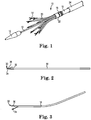
- FIGs 2 and 3 illustrate one embodiment of a capturing wire 14 of a delivery system of the invention, such as delivery system 10.
- Capturing wire 14 is preferably an elongated piece of a shape-memory material, such as Nitinol, having a distal end 30 that is configured for attachment to a stent frame.
- Figure 2 illustrates this capturing wire 14 in a "closed" configuration in which its distal end 30 has been cut or otherwise formed into multiple sections or pieces, such as can be performed using laser cutting techniques, EDM, and the like.
- Figure 3 illustrates the same wire 14 after it has been placed in a forming fixture or otherwise manipulated to provide a certain bent or curved wire configuration, such as the relatively curved shape shown.
Description
- The present invention relates to prosthetic heart valves. More particularly, it relates to devices, and delivery systems for percutaneously implanting prosthetic heart valves.
US 2004/236406 A1 describes a mechanism to improve stent securement.US 2008/0262592 A1 describes an intraluminary stent relocating apparatus. - Diseased or otherwise deficient heart valves can be repaired or replaced using a variety of different types of heart valve surgeries. Typical heart valve surgeries involve an open-heart surgical procedure that is conducted under general anesthesia, during which the heart is stopped while blood flow is controlled by a heart-lung bypass machine. This type of valve surgery is highly invasive and exposes the patient to a number of potentially serious risks, such as infection, stroke, renal failure, and adverse effects associated with use of the heart-lung machine, for example.
- Recently, there has been increasing interest in minimally invasive and percutaneous replacement of cardiac valves. Such surgical techniques involve making a small opening in the skin of the patient into which a valve assembly is inserted in the body and delivered to the heart via a delivery device similar to a catheter. This technique is often preferable to more invasive forms of surgery, such as the open-heart surgical procedure described above. In the context of pulmonary valve replacement,
U.S. Patent Application Publication Nos. 2003/0199971 A1 and2003/0199963 A1, both filed by Tower, et al. , describe a valved segment of bovine jugular vein, mounted within an expandable stent, for use as a replacement pulmonary valve. The replacement valve is mounted on a balloon catheter and delivered percutaneously via the vascular system to the location of the failed pulmonary valve and expanded by the balloon to compress the valve leaflets against the right ventricular outflow tract, anchoring and sealing the replacement valve. As described in the articles: "Percutaneous Insertion of the Pulmonary Valve", Bonhoeffer, et al., Journal of the American College of Cardiology 2002; 39: 1664 - 1669 and "Transcatheter Replacement of a Bovine Valve in Pulmonary Position", Bonhoeffer, et al., Circulation 2000; 102: 813 - 816, the replacement pulmonary valve may be implanted to replace native pulmonary valves or prosthetic pulmonary valves located in valved conduits. - Various types and configurations of prosthetic heart valves are used in percutaneous valve procedures to replace diseased natural human heart valves. The actual shape and configuration of any particular prosthetic heart valve is dependent to some extent upon the valve being replaced (i.e., mitral valve, tricuspid valve, aortic valve, or pulmonary valve). In general, the prosthetic heart valve designs attempt to replicate the function of the valve being replaced and thus will include valve leaflet-like structures used with either bioprostheses or mechanical heart valve prostheses. In other words, the replacement valves may include a valved vein segment that is mounted in some manner within an expandable stent to make a stented valve. In order to prepare such a valve for percutaneous implantation, the stented valve can be initially provided in an expanded or uncrimped condition, then crimped or compressed around the balloon portion of a catheter until it is as close to the diameter of the catheter as possible.
- Other percutaneously-delivered prosthetic heart valves have been suggested having a generally similar configuration, such as by Bonhoeffer, P. et al., "Transcatheter Implantation of a Bovine Valve in Pulmonary Position." Circulation, 2002; 102:813-816, and by Cribier, A. et al. "Percutaneous Transcatheter Implantation of an Aortic Valve Prosthesis for Calcific Aortic Stenosis." Circulation, 2002; 106:3006-3008. These techniques rely at least partially upon a frictional type of engagement between the expanded support structure and the native tissue to maintain a position of the delivered prosthesis, although the stents can also become at least partially embedded in the surrounding tissue in response to the radial force provided by the stent and balloons that are sometimes used to expand the stent. Thus, with these transcatheter techniques, conventional sewing of the prosthetic heart valve to the patient's native tissue is not necessary. Similarly, in an article by Bonhoeffer, P. et al. titled "Percutaneous Insertion of the Pulmonary Valve." J Am Coll Cardiol, 2002; 39:1664-1669, percutaneous delivery of a biological valve is described. The valve is sutured to an expandable stent within a previously implanted valved or non-valved conduit, or a previously implanted valve. Again, radial expansion of the secondary valve stent is used for placing and maintaining the replacement valve.
- Although there have been advances in percutaneous valve replacement techniques and devices, there is a continued desire to provide different designs of delivery systems that can be used to implant valves in a minimally invasive and percutaneous manner. There is also a continued desire to be able to reposition and/or retract the valves once they have been deployed or partially deployed in order to ensure optimal placement of the valves within the patient.
- Replacement heart valves that can be used with delivery systems of the invention each include a stent or support frame within which a valve structure can be attached. The stents used with delivery systems and methods of the invention include a wide variety of structures and features that can be used alone or in combination with other stent features to achieve a desired result. In particular, these stents can provide a number of different docking and/or anchoring structures that are conducive to percutaneous delivery thereof. Many of the stent structures are thus compressible to a relatively small diameter for percutaneous delivery to the heart of the patient, and then are expandable either via removal of external compressive forces (e.g., self-expanding stents), or through application of an outward radial force (e.g., balloon expandable stents). The devices delivered by the delivery systems described herein can also be used to deliver stents, valved stents, or other interventional devices such as ASD (atrial septal defect) closure devices, VSD (ventricular septal defect) closure devices, or PFO (patent foramen ovale) occluders.
- Methods for insertion of replacement heart valves include the use of delivery systems that can maintain stent structures in their compressed state during their insertion and allow or cause the stent structures to radially expand once they are in their desired location. In particular, the methods of implanting a stent can include the use of delivery systems having a plurality of wires, each of which includes a distal end with a slot for capturing a crown or other structural feature of a stent. Each end can further include a moveable flap or extension that helps to hold the stent crown within the slot to allow for positive, consistent release of the stent from the delivery system without the associated complications that can be caused by incomplete release and/or sticking that can occur with other delivery systems.
- Delivery systems and methods can include features that allow the stents to be retrieved for removal or relocation thereof after they have been deployed or partially deployed from the stent delivery systems. The methods of implantation of the stent structures may include using either an antegrade or retrograde approach. Further, in many the delivery approaches, the stent structure is rotatable in vivo to allow the stent structure to be positioned in a desired orientation.
- Herein is disclosed, in accordance with appended claim 1, a delivery system (10) for delivering a stent (50), including a plurality of capturing wires (14) and a plurality of sleeves (20). Each of the sleeves at least partially surrounds a respective capturing wire (14) of the plurality of capturing wires (14). Each capturing wire includes a distal end (30) configured for attachment to a stent frame, the distal end (30) including an opening or slot (32) between a lower portion (34) and an upper portion (36). The lower portion (34) is moveable relative to the upper portion (36) between an open position and a closed position.
- The present invention will be further explained with reference to the appended Figures, wherein like structure is referred to by like numerals throughout the several views, and wherein:
-
Figure 1 is a perspective view of a distal end portion of an exemplary embodiment of a transcatheter stent or stented valve delivery system; -
Figure 2 is a side view of a capturing wire of the delivery system ofFigure 1 , with its distal end in a closed position; -
Figure 3 is another side view of the capturing wire ofFigure 2 , with its distal end in an open position; -
Figure 4 is a perspective view of one step of loading a stent onto a distal end portion of a transcatheter delivery system, wherein the stent is not yet positively engaged with the capturing wires; -
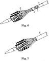
Figures 5-7 are perspective views of three sequential steps of loading a stent onto the distal end portion of the delivery system ofFigure 1 , which illustrates the stent as it is positively engaged with capturing wires; -
Figure 8 is a perspective view of a delivery system, such as it can be configured when a stent is fully captured within a sheath; -
Figure 9 is an enlarged front view of a portion of a stent adjacent to the distal ends of the capture wires of a delivery system; -
Figure 10 is a perspective view of a valved stent of the type that can be delivered by the delivery systems; -
Figures 11-14 are front views of a proximal end of a delivery system, which illustrates exemplary sequential steps in the process of loading a stent onto the delivery system; -
Figures 15-17 are perspective views of capturing wires of a delivery system adjacent to wires of a stent; and -
Figures 18 and19 are front enlarged views of a portion of a stent as it is being released from the distal ends of capturing wires of a delivery system. - As referred to herein, the prosthetic heart valves used in accordance with the various devices and methods of heart valve delivery may include a wide variety of different configurations, such as a prosthetic heart valve having tissue leaflets or a synthetic heart valve having polymeric, metallic, or tissue-engineered leaflets, and can be specifically configured for replacing any heart valve. That is, while much of the description herein refers to replacement of aortic valves, the prosthetic heart valves can also generally be used for replacement of native mitral, pulmonic, or tricuspid valves, for use as a venous valve, or to replace a failed bioprosthesis, such as in the area of an aortic valve or mitral valve, for example. Further, while much of the description herein refers to a transcatheter valve delivery system, the delivery system can alternatively be used as an apical delivery system.
- Each of the valves used with the delivery devices and methods described herein can include leaflets attached within an interior area of a stent, such as a
stent 50 of the type that is illustrated inFigure 10 , which includes a valve mounted with three leaflets within its interior opening. This leaflet configuration is exemplary, and it is noted that leaflets are not shown in many of the illustrated embodiments herein in order to provide a better view of the features of the delivery systems. In general, the stents used with the delivery systems and methods described herein include a support structure comprising a number of strut or wire portions arranged relative to each other to provide a desired compressibility and strength to the heart valve. Although a number of different configurations of stents can be used, in general terms, the stents described herein are generally tubular or cylindrical support structures, although the diameter and shape can vary along the length of the stent. - Valve leaflets can be secured within the internal area of one of the support structures to provide a valved stent. The leaflets can be formed from a variety of materials, such as autologous tissue, xenograph material, or synthetics, as are known in the art. The leaflets may be provided as a homogenous, biological valve structure, such as a porcine, bovine, or equine valve. Alternatively, the leaflets can be provided independent of one another (e.g., bovine or equine pericardial leaflets) and subsequently assembled to the support structure of the stent. In another alternative, the stent structure and leaflets can be fabricated at the same time, such as may be
accomplished using high strength nano-manufactured NiTi films of the type produced by Advanced Bio Prosthetic Surfaces Ltd. (ABPS) of San Antonio, Texas, for example. The support structures are generally configured to accommodate three leaflets; however, it is understood that the prosthetic heart valves delivered by the methods and delivery systems of the invention can incorporate more or less than three leaflets. - In more general terms, the combination of a support structure with one or more leaflets can assume a variety of other configurations that differ from those shown and described, including any known prosthetic heart valve design. In certain embodiments of the invention, the support structure with leaflets can be any known expandable prosthetic heart valve configuration, whether balloon expandable, self-expanding, or unfurling (as described, for example, in
U.S. Patent Nos. 3,671,979 ;4,056,854 ;4,994,077 ;5,332,402 ;5,370,685 ;5,397,351 ;5,554,185 ;5,855,601 ; and6,168,614 ;U.S. Patent Application Publication No. 2004/0034411 ; Bonhoeffer P., et al., "Percutaneous Insertion of the Pulmonary Valve", Pediatric Cardiology, 2002; 39:1664-1669; Anderson H R, et al., "Transluminal Implantation of Artificial Heart Valves", EUR Heart J., 1992; 13:704-708; Anderson, J. R., et al., "Transluminal Catheter Implantation of New Expandable Artificial Cardiac Valve", EUR Heart J., 1990, 11: (Suppl) 224a; Hilbert S. L., "Evaluation of Explanted Polyurethane Trileaflet Cardiac Valve Prosthesis", J Thorac Cardiovascular Surgery, 1989; 94:419-29; Block P C, "Clinical and Hemodyamic Follow-Up After Percutaneous Aortic Valvuloplasty in the Elderly", The American Journal of Cardiology, Vol. 62, Oct. 1, 1998; Boudjemline, Y., "Steps Toward Percutaneous Aortic Valve Replacement", Circulation, 2002; 105:775-558; Bonhoeffer, P., "Transcatheter Implantation of a Bovine Valve in Pulmonary Position, a Lamb Study", Circulation, 2000:102:813-816; Boudjemline, Y., "Percutaneous Implantation of a Valve in the Descending Aorta In Lambs", EUR Heart J, 2002; 23:1045-1049; Kulkinski, D., "Future Horizons in Surgical Aortic Valve Replacement: Lessons Learned During the Early Stages of Developing a Transluminal Implantation Technique", ASAIO J, 2004; 50:364-68). - Optional orientation and positioning of the stents using delivery systems of the invention may be accomplished either by self-orientation of the stents (such as by interference between features of the stent and a previously implanted stent or valve structure) or by manual orientation of the stent to align its features with anatomical or previous bioprosthetic features, such as can be accomplished using fluoroscopic visualization techniques, for example. For example, when aligning stents with native anatomical structures using delivery systems of the invention, they should be aligned so as to not block the coronary arteries, and native mitral or tricuspid valves should be aligned relative to the anterior leaflet and/or the trigones/commissures.
- The support structures of the stents can be wires formed from a shape-memory material such as a nickel titanium alloy (e.g., Nitinol). With such a shape-memory material, the support structure will be self-expandable from a contracted state to an expanded state, such as by the application of heat, energy, and the like, or by the removal of external forces (e.g., compressive forces of the type that can be provided by a moveable sheath). Such a support structure can preferably be repeatedly compressed and expanded without damaging the structure of the stent. In one embodiment, the support structure of such an embodiment may be cut (e.g., laser cut) from a single piece of material. In another embodiment, the support structure may be assembled from a number of different components. For these types of stent structures, one example of a delivery system that can be used includes a catheter with a retractable sheath that covers the stent until it is to be deployed, at which point the sheath can be retracted to allow the stent to expand.
- The stents or support structures used with the delivery systems of the invention can alternatively include a series of wires or wire segments configured so that they are capable of transitioning from a collapsed state to an expanded state with the application or removal of external and/or internal forces. The wires comprising the support structure can be formed of a metal or other material. Further, the wires are arranged in such a way that the stent or support structure can be folded or compressed to a contracted state in which its internal diameter is considerably smaller than its internal diameter when the structure is in an expanded state. In its collapsed state, such a support structure with an attached valve can be mounted over a delivery device, such as a balloon catheter, for example. The support structure is configured so that it can be changed to its expanded state when desired, such as by the expansion of a balloon catheter or removal of external forces that are provided by a sheath, for example. The delivery systems used for such a stent can be provided with degrees of rotational and axial orientation capabilities in order to properly position the new stent at its desired location.
- Referring now to the Figures, wherein the components are labeled with like numerals throughout the several Figures, and initially to
Figure 1 , one embodiment of adelivery system 10 is illustrated, which can be used to deploy a stent, such as a valved stent, in a desired location in a patient. This delivery system allows a stent to be loaded and delivered to a desired location, then is used for at least partially deploying the stent, and then can optionally be used for recapturing the stent and relocating it, if desired. In general,delivery system 10 includes adistal tip 12 from which anelongated member 13 extends and an opposite proximal end that includes many of the control features for the delivery system. Thedistal tip 12 can provide a surface against which a sheath can be sealed, along with providing a sleeve actuation function, as will be described below. -
Delivery system 10 further includes multiple capturingwires 14, each of which is attached to awire connection member 16 at or near its proximal end. The outer surface of themember 16 may be sized and shaped to be cylindrical to generally match the inner size and shape of a sheath that will be slid over themember 16, as will be discussed in further detail below. It is understood, however, that the size and shape of the outer surface ofmember 16 can be differently configured. - In the illustrated embodiment, the capturing
wires 14 are spaced from each other in a radial pattern to extend from the distal end ofmember 16, and in one particular embodiment, thedelivery system 10 includes nine capturingwires 14 that are spaced evenly from each other (i.e., at approximately 40 degrees from each other) relative to the distal end ofmember 16. Such an embodiment would typically be used with a stent having nine crowns or attachments points, so that the number of capturing wires matches the number of crowns or attachment points of a corresponding stent. However, it is contemplated that the number of capturingwires 14 is different than the number of crowns or attachment points of a corresponding stent and/or that the number of capturing wires is more or less than nine. It is further contemplated that the capturingwires 14 are not evenly spaced from each other, but that some of thewires 14 are closer toadjacent wires 14 than others and/or that thewires 14 are spaced at either the same or different distances from an outer surface of themember 16. That is, the wires can be located at the same distance from a longitudinal axis of the delivery system, or can optionally be positioned at staggered distances from the longitudinal axis of the delivery system, such as to accommodate a stent that has a certain corresponding configuration. In any case, the assembly that is made up of themember 16 with extending capturingwires 14 can in turn be attached to anextension tube 18. Theextension tube 18 can be attached to or extend from a handle (not shown) at its proximal end. - Each of the capturing
wires 14 is at least partially surrounded by a sleeve 20 (shown enlarged inFigure 9 ), wherein each of thesleeves 20 extends from, and/or can be attached to, a distal end of asleeve connector member 22. As shown,connector member 22 is distal towire connection member 16, wherein thesemembers member 22 may be sized and shaped to be cylindrical to generally match the inner size and shape of a sheath that will be slid over themember 22, as will be discussed in further detail below. It is understood, however, that the size and shape of the outer surface ofmember 22 can be differently configured. - The radial arrangement of the
sleeves 20 relative to a distal end ofconnector member 22 is generally the same as the radial arrangement of the capturingwires 14 relative the distal end ofmember 16. Each of thesesleeves 20 is positioned to enclose or partially enclose acorresponding capturing wire 14. Further, each of thesleeves 20 of this embodiment is axially slideable relative to itsrespective capturing wire 14. In one embodiment, thesleeves 20 are made of a flexible or semi-flexible material such that sliding of the sleeves relative to the capturingwires 14 does not change the formed shape of any of the capturingwires 14. - The
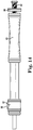
delivery system 10 further includes a sleeve actuator that extends from the proximal end of the delivery system to thedistal tip 12, which is attached to theconnector member 22. The sleeve actuator atdistal tip 12 can consist of a small tube that allows passage of a guide wire through it, along with a dilator tip at its distal end. The sleeve actuator can move freely relative to theextension tube 18, and can be affixed to an actuating mechanism (e.g., a drive screw, thumb slide, or the like) at its proximal end, such assleeve actuator 84 ofFigure 11-14 . This actuation mechanism can be attached within a handle at the proximal end of thedelivery system 10, for example, in order to remotely control the axial movement of thesleeves 20 in their proximal and distal directions, as is illustrated inFigures 11-14 , for example. -
Figure 11 illustrates a proximal end of a delivery system of the invention, which generally includes ahandle body 80 that is attached toextension tube 18, along with asheath actuator 82 that includes athumb lock 86, and asleeve actuator 84. In one embodiment,sleeve actuator 84 includes aknob 90 positioned on a threadedrod 92, as illustrated. One exemplary method of operating of these components of a delivery system is described in further detail below. - Referring again to
Figure 1 ,delivery system 10 further includes asheath 24, which is sized to be able to surround the sleeves, capturing wires, and the connector members to which the sleeves and capturing wires are attached.Sheath 24 is axially moveable in a proximal and distal direction relative to thedistal tip 12 via an actuating mechanism, such assheath actuator 82 ofFigures 11-14 , for example. Such an actuator can be located at or near the proximal end of the delivery system to facilitate axial movement of the sheath. In one embodiment, the inner surface of thesheath 24 can be slightly larger than a proximal end of thedistal tip 12 in order to be able to mate with it and completely encompass the various stent delivery components at the distal end of the device. In this way, thesheath 24 can help to provide a smooth surface for delivery of a stent through the vasculature of the patient. -
Figures 2 and 3 illustrate one embodiment of acapturing wire 14 of a delivery system of the invention, such asdelivery system 10. Capturingwire 14 is preferably an elongated piece of a shape-memory material, such as Nitinol, having adistal end 30 that is configured for attachment to a stent frame.Figure 2 illustrates thiscapturing wire 14 in a "closed" configuration in which itsdistal end 30 has been cut or otherwise formed into multiple sections or pieces, such as can be performed using laser cutting techniques, EDM, and the like.Figure 3 illustrates thesame wire 14 after it has been placed in a forming fixture or otherwise manipulated to provide a certain bent or curved wire configuration, such as the relatively curved shape shown.Distal end 30 ofwire 14 includes an opening orslot 32, which is positioned between alower portion 34 and anupper portion 36.Upper portion 36 can be generally fixed to extend in the same general direction as the longitudinal axis of thewire 14, as shown, although it can instead be configured so that it extends in a different direction (e.g., bent or curved) relative to the longitudinal axis of thewire 14.Lower portion 34 is moveable relative to theupper portion 36 so that extends in a direction that is generally not parallel to the longitudinal axis of thewire 14 and theupper portion 36, as is shown inFigure 3 . As is further illustrated inFigure 3 , capturingwire 14 is bent or angled along its length, wherein the particular angle of the sections of the wire relative to each other is selected for engagement with a stent having a certain configuration, as is explained below relative to an exemplary process of capturing, delivering, and deploying an expandable stent. - The configuration for the
distal end 30 of the capturingwires 14 illustrated herein is one exemplary wire embodiment, wherein it is understood that thedistal end 30 may be configured differently than shown, while remaining within the scope of the invention. That is, the distal end can include a slot or opening that is larger or smaller than shown, or that has a different shape than the illustrated rectangular slot shape, such as circular or contoured. In any case, the configuration of this distal end desirably will provide for both secure capture of the stent structure along with relatively easy release of the stent from the delivery system, when desired. Thus, the slot or opening in one embodiment can be at least slightly larger than the outer size and shape of the stent wire that it will be capturing in order for the upper and lower portions to completely enclose the wire crowns of a stent. However, the slot or opening in the end of thecapturing wire 14 may instead be smaller than the wire of the stent with which it will be engaged. -
Figures 4-8 illustrate multiple sequential steps of an exemplary process of loading astent 50 onto thedelivery system 10 described above, although it is understood that thedelivery system 10 can deliver stents having a different configuration than is illustrated in these figures. In any case, thestent 50 includes a series of wires or wire segments arranged so that they are capable of transitioning from a collapsed state to an expanded state, as described above, and preferably is a self-expanding stent comprising a shape-memory material.Delivery system 10 can be prepared for loadingstent 50 thereon by first positioning thestent 50 in its expanded or semi-expanded condition generally at the distal end of thedelivery system 10 and over itsdistal tip 12, as is illustrated inFigure 4 . At this point, the components at the proximal end of the delivery system can generally be positioned as shown inFigure 11 , for example, with thesheath actuator 82 at a generally proximal location (i.e., adjacent to handle body 80) and theknob 90 proximally positioned along threaded section 92 (i.e., relatively close to the proximal end of the delivery system and spaced from the handle body 80). In this position, the proximal end ofstent 50 is located generally adjacent to the distal end of the capturingwires 14, wherein the lower andupper portions wire 14 are moveable relative to each other to allow access to the opening orslot 32 between them. - Next, a single crown of the
stent 50 is positioned within one of theslots 32, as is illustrated inFigure 15 . In particular, one crown ofstent 50 is placed between the lower andupper portions wires 14. Anadditional capturing wire 14 can be hooked onto a crown of thestent 50, as is illustrated inFigure 16 . Thissecond wire 14 can be located at approximately 160 degrees from thefirst wire 14, for example, which is located on the approximate opposite side of the stent for a nine crown stent. Such a loading sequence is optional, but can provide for additional stability in the stent-loading process. Thissecond wire 14 can then be compressed inwardly while thelower portion 34 of thewire 14 is positioned relative to the corresponding crown ofstent 50. The outward spring force of thewire 14 acts to lock the raised area of thelower portion 34 into the crown of thestent 50. Next, athird wire 14 can be hooked onto another crown of thestent 50, as is illustrated inFigure 17 , which may be selected from any of the remainingwires 14 that are not yet attached to a stent crown. The attachment of thethird wire 14 tends to further stabilize thestent 50 relative to the distal end of the wires. The remainingwires 14 can then be hooked onto the remaining stent crowns, as is illustrated inFigure 5 . - The next step of loading
stent 50 ontodelivery system 10 is illustrated inFigure 6 and includes moving thesleeves 20 toward the distal ends of the capturingwires 14 via a mechanism at the proximal end of the delivery system. In particular, theknob 90 ofsleeve actuator 84 is rotated to advance it along the threadedsection 92, as is shown inFigure 12 , thereby advancing thesleeves 20 in a distal direction. As thesleeves 20 are moved closer to the distal ends 30 of capturingwires 14, the upper andlower portions elongated member 13 is attached to thesleeve cylinder 22, which in turn is attached to theknob 90 ofsleeve actuator 84. It is possible that the system is configured so that thedistal tip 12 does not move when advancing thesleeves 20. Referring again toFigure 6 , thesleeve cylinder 22 is now spaced further from theadjacent connection cylinder 16 and closer to thedistal tip 12. This movement locks the stent crowns in place relative to the distal ends 30 of the capturingwires 14 by forcing the lower andupper portions wires 14 together. - Next,
sheath 24 is moved in a distal direction toward thedistal tip 12 to compress the stent structure and surround thestent 50 and the mechanisms that are attaching the stent to thedelivery system 10. This may be accomplished by depressing thethumb lock 86 to allow thesheath actuator 82 to slide forward, as is illustrated inFigure 13 . Because thesheath 24 is attached to thesheath actuator 82, this movement of theactuator 82 causes the corresponding movement of thesheath 24 toward thedistal tip 12, as is illustrated inFigure 7 . Further movement of thesheath 24 in a distal direction will compress the capturingwires 14 toward a longitudinal axis of the delivery system, which will force them against their outward bias or splaying, as illustrated and described herein. -
Figure 8 illustrates one exemplary position of thedelivery system 10 with a stent in its fully loaded condition, where thesheath 24 has been moved all the way to thedistal tip 12 so that thestent 50 and components used to attach it to the delivery system are all enclosed within thesheath 24. An exemplary corresponding position of thesheath actuator 82 relative to thehandle body 80 is illustrated inFigure 14 , where theactuator 82 is located at its furthest distance from thehandle body 80 when thesheath 84 is moved to its most distal location relative todistal tip 12. - It is understood that while the distal end features of the capturing wires described herein are generally shown to be engaging with the end crowns of a stent, the distal end features can additionally or alternatively engage with intermediate stent crowns or other stent features.
- After the
stent 50 is loaded onto thedelivery system 10 and enclosed within thesheath 24, as illustrated inFigure 8 , the delivery system can be inserted into the desired stent deployment location with the patient (e.g., the area adjacent to the native aortic valve). In order to deploy the stent after it has been properly positioned in the patient, thesheath 24 can be pulled back to expose thestent 50 and the capturingwires 14 engaged with the crowns of thestent 50, as is illustrated inFigure 18 . In particular,Figure 18 illustrates the position of the delivery system components, such as thesleeves 20, relative to thestent 50 just prior to the configuration shown inFigure 9 . It is noted that at the point in the process illustrated inFigure 18 , the stent (and valve) could be pulled back into the sheath and repositioned within the patient, if desired. However, once the user is satisfied with the position of the stent, thesleeves 20 can be retracted even further to allow the distal ends of thewires 14 to open, thereby releasing thestent 50 completely. That is, thesleeves 20 can be retracted by moving thesleeve cylinder 22 in a proximal direction relative to the ends of the capturingwires 14. The capturingwires 14 are designed so that when positioned in a desired deployment location, retracting thesleeves 20 will cause thelower portions 34 of the capturingwires 14 to pull away or disengage from the stent crowns because theupper portions 36 rest against thevessel wall 99, thereby releasing the stent from the capturingwires 14, as is illustrated inFigure 9 . - At this point, the
stent 50 can be considered to be deployed in its implantation location, such that the delivery system can then be moved in a proximal direction until the distal ends 30 of the capturingwires 14 are clear of the stent, as shown inFigure 19 . If desired, thesheath 24 can then be moved back toward thedistal tip 12 of thedelivery system 10 to enclose the wire connection components, which can help to prevent possible undesirable interference between the capturingwires 14 and the stent or surrounding tissue of the patient. Thedelivery system 10 can then be removed from the patient. Optionally, each of the plurality of sleeves comprises axially translating the sleeve actuator, and wherein the steps of axially translating the sheath toward and away from the distal tip comprises axially translating the sheath actuator. - The present invention has now been described with reference to at least one embodiment thereof. The foregoing detailed description and examples have been given for clarity of understanding only. No unnecessary limitations are to be understood therefrom. It will be apparent to those skilled in the art that many changes can be made in the embodiments described without departing from the scope of the invention. Thus, the scope of the present invention should not be limited to the structures described herein, but only by the structures described by the language of the claims.
Claims (13)
- A delivery system (10) for delivering a stent (50), comprisinga plurality of capturing wires (14) anda plurality of sleeves (20), each of which at least partially surrounds a respective capturing wire (14) of the plurality of capturing wires (14), each capturing wire comprising
a distal end (30) configured for attachment to a stent frame, the distal end (30) including an opening or slot (32) between a lower portion (34) and an upper portion (36), the lower portion (34) being moveable relative to the upper portion (36) between an open position and a closed position. - The delivery system (10) for delivering a stent (50) of claim 1, wherein
a slot (32) is defined by the upper and lower portions (34, 36) when they are in the closed position. - The delivery system (10) for delivering a stent (50) of any preceding claim, wherein
the capturing wire (14) is curved, bent, or angled along its length. - The delivery system (10) for delivering a stent (50) of any preceding claim, wherein
the upper portion (36) is fixed to extend in the same general direction as the longitudinal axis of the capturing wire (14). - The delivery system (10) for delivering a stent (50) of any preceding claim, wherein
the upper portion (36) extends in a different direction relative to the longitudinal axis of the capturing wire (14). - The delivery system (10) for delivering a stent (50) of any preceding claim, wherein
the lower portion (34) extends in a direction generally not parallel to the longitudinal axis of the capturing wire (14) and the upper portion (36). - The delivery system (10) for delivering a stent (50) of any preceding claim, wherein
the slot (32) is rectangular, circular or contoured. - The delivery system (10) for delivering a stent (50) of any preceding claim,
wherein the capturing wire (14) is made of a shape-memory material such as nitinol - The delivery system (10) of any preceding claim, wherein each of the sleeves (20) is slideable along at least a portion of a length of a respective capturing wire (14).
- The delivery system (10) of any preceding claim, wherein each of the sleeves (20) is tubular and comprises an internal opening that is positionable to surround the distal end (30) of the respective capturing wire (14) when the upper and lower portions (34, 36) are in their closed position.
- The delivery system (10) of any preceding claim, further comprising a sleeve connection member (22) positioned between a wire connection member (16) and a distal tip (12) of an elongated member (13), wherein each of the sleeves (20) extends from a distal end of the sleeve connection member (22), and wherein the sleeve connection member (22) is axially translatable to move the sleeves (20) axially relative to their respective capturing wires (14).
- The delivery system (10) of any preceding claim, further comprising a sheath (24) that is slideable relative to the distal tip (12) of the elongated member (13), wherein the sheath comprises an internal area for surrounding the plurality of capturing wires (14) and the wire connection member (16).
- A method of loading a stent (50) onto a delivery system (10), comprising:placing a crown of a stent (50) between the upper and lower portions (34, 36) of a capturing wire (14) of the delivery system (10) of any preceding claim; andforcing the lower and upper portions (34, 36) together.
Applications Claiming Priority (3)
| Application Number | Priority Date | Filing Date | Title |
|---|---|---|---|
| US32722210P | 2010-04-23 | 2010-04-23 | |
| EP11718580.1A EP2560589B1 (en) | 2010-04-23 | 2011-04-21 | Delivery systems for prosthetic heart valves |
| PCT/US2011/033463 WO2011133792A1 (en) | 2010-04-23 | 2011-04-21 | Delivery systems and methods of implantation for prosthetic heart valves |
Related Parent Applications (1)
| Application Number | Title | Priority Date | Filing Date |
|---|---|---|---|
| EP11718580.1A Division EP2560589B1 (en) | 2010-04-23 | 2011-04-21 | Delivery systems for prosthetic heart valves |
Publications (2)
| Publication Number | Publication Date |
|---|---|
| EP3384879A1 EP3384879A1 (en) | 2018-10-10 |
| EP3384879B1 true EP3384879B1 (en) | 2020-09-30 |
Family
ID=44237212
Family Applications (2)
| Application Number | Title | Priority Date | Filing Date |
|---|---|---|---|
| EP11718580.1A Active EP2560589B1 (en) | 2010-04-23 | 2011-04-21 | Delivery systems for prosthetic heart valves |
| EP18172381.8A Active EP3384879B1 (en) | 2010-04-23 | 2011-04-21 | Delivery systems for prosthetic heart valves |
Family Applications Before (1)
| Application Number | Title | Priority Date | Filing Date |
|---|---|---|---|
| EP11718580.1A Active EP2560589B1 (en) | 2010-04-23 | 2011-04-21 | Delivery systems for prosthetic heart valves |
Country Status (4)
| Country | Link |
|---|---|
| US (3) | US9629719B2 (en) |
| EP (2) | EP2560589B1 (en) |
| CN (1) | CN102858275A (en) |
| WO (1) | WO2011133792A1 (en) |
Cited By (1)
| Publication number | Priority date | Publication date | Assignee | Title |
|---|---|---|---|---|
| US11844498B2 (en) | 2015-02-23 | 2023-12-19 | Uroviu Corporation | Handheld surgical endoscope |
Families Citing this family (197)
| Publication number | Priority date | Publication date | Assignee | Title |
|---|---|---|---|---|
| US8758372B2 (en) | 2002-08-29 | 2014-06-24 | St. Jude Medical, Cardiology Division, Inc. | Implantable devices for controlling the size and shape of an anatomical structure or lumen |
| ES2349952T3 (en) | 2002-08-29 | 2011-01-13 | St. Jude Medical, Cardiology Division, Inc. | IMPLANTABLE DEVICES FOR CONTROLLING THE INTERNAL CIRCUMFERENCE OF AN ANATOMICAL ORIFICE OR LUMEN. |
| US8840663B2 (en) | 2003-12-23 | 2014-09-23 | Sadra Medical, Inc. | Repositionable heart valve method |
| US11278398B2 (en) | 2003-12-23 | 2022-03-22 | Boston Scientific Scimed, Inc. | Methods and apparatus for endovascular heart valve replacement comprising tissue grasping elements |
| US7988724B2 (en) | 2003-12-23 | 2011-08-02 | Sadra Medical, Inc. | Systems and methods for delivering a medical implant |
| US20050137687A1 (en) | 2003-12-23 | 2005-06-23 | Sadra Medical | Heart valve anchor and method |
| US8603160B2 (en) | 2003-12-23 | 2013-12-10 | Sadra Medical, Inc. | Method of using a retrievable heart valve anchor with a sheath |
| US9526609B2 (en) | 2003-12-23 | 2016-12-27 | Boston Scientific Scimed, Inc. | Methods and apparatus for endovascularly replacing a patient's heart valve |
| US7381219B2 (en) | 2003-12-23 | 2008-06-03 | Sadra Medical, Inc. | Low profile heart valve and delivery system |
| US7959666B2 (en) * | 2003-12-23 | 2011-06-14 | Sadra Medical, Inc. | Methods and apparatus for endovascularly replacing a heart valve |
| US8052749B2 (en) | 2003-12-23 | 2011-11-08 | Sadra Medical, Inc. | Methods and apparatus for endovascular heart valve replacement comprising tissue grasping elements |
| US20120041550A1 (en) | 2003-12-23 | 2012-02-16 | Sadra Medical, Inc. | Methods and Apparatus for Endovascular Heart Valve Replacement Comprising Tissue Grasping Elements |
| WO2006063199A2 (en) | 2004-12-09 | 2006-06-15 | The Foundry, Inc. | Aortic valve repair |
| DE102005003632A1 (en) | 2005-01-20 | 2006-08-17 | Fraunhofer-Gesellschaft zur Förderung der angewandten Forschung e.V. | Catheter for the transvascular implantation of heart valve prostheses |
| US8864823B2 (en) | 2005-03-25 | 2014-10-21 | StJude Medical, Cardiology Division, Inc. | Methods and apparatus for controlling the internal circumference of an anatomic orifice or lumen |
| EP2767260B1 (en) | 2005-03-25 | 2019-07-03 | St. Jude Medical, Cardiology Division, Inc. | Apparatus for controlling the internal circumference of an anatomic orifice or lumen |
| US20070213813A1 (en) | 2005-12-22 | 2007-09-13 | Symetis Sa | Stent-valves for valve replacement and associated methods and systems for surgery |
| EP2111189B1 (en) | 2007-01-03 | 2017-04-05 | St. Jude Medical, Cardiology Division, Inc. | Implantable devices for controlling the size and shape of an anatomical structure or lumen |
| US7896915B2 (en) | 2007-04-13 | 2011-03-01 | Jenavalve Technology, Inc. | Medical device for treating a heart valve insufficiency |
| DE102007043830A1 (en) | 2007-09-13 | 2009-04-02 | Lozonschi, Lucian, Madison | Heart valve stent |
| US8157852B2 (en) * | 2008-01-24 | 2012-04-17 | Medtronic, Inc. | Delivery systems and methods of implantation for prosthetic heart valves |
| ES2903231T3 (en) | 2008-02-26 | 2022-03-31 | Jenavalve Tech Inc | Stent for positioning and anchoring a valve prosthesis at an implantation site in a patient's heart |
| US9044318B2 (en) | 2008-02-26 | 2015-06-02 | Jenavalve Technology Gmbh | Stent for the positioning and anchoring of a valvular prosthesis |
| CN102245256B (en) | 2008-10-10 | 2014-07-23 | 萨德拉医学公司 | Medical devices and delivery systems for delivering medical devices |
| WO2010085649A1 (en) | 2009-01-22 | 2010-07-29 | St. Jude Medical | Post-operative adjustment tool, minimally invasive attachment apparatus, and adjustable tricuspid ring |
| US8870950B2 (en) | 2009-12-08 | 2014-10-28 | Mitral Tech Ltd. | Rotation-based anchoring of an implant |
| US20110224785A1 (en) | 2010-03-10 | 2011-09-15 | Hacohen Gil | Prosthetic mitral valve with tissue anchors |
| WO2011133792A1 (en) * | 2010-04-23 | 2011-10-27 | Medtronic Inc. | Delivery systems and methods of implantation for prosthetic heart valves |
| US8579964B2 (en) | 2010-05-05 | 2013-11-12 | Neovasc Inc. | Transcatheter mitral valve prosthesis |
| CN103002833B (en) | 2010-05-25 | 2016-05-11 | 耶拿阀门科技公司 | Artificial heart valve and comprise artificial heart valve and support through conduit carry interior prosthese |
| US8992604B2 (en) | 2010-07-21 | 2015-03-31 | Mitraltech Ltd. | Techniques for percutaneous mitral valve replacement and sealing |
| US11653910B2 (en) | 2010-07-21 | 2023-05-23 | Cardiovalve Ltd. | Helical anchor implantation |
| US9132009B2 (en) | 2010-07-21 | 2015-09-15 | Mitraltech Ltd. | Guide wires with commissural anchors to advance a prosthetic valve |
| US9763657B2 (en) | 2010-07-21 | 2017-09-19 | Mitraltech Ltd. | Techniques for percutaneous mitral valve replacement and sealing |
| EP2613737B2 (en) | 2010-09-10 | 2023-03-15 | Symetis SA | Valve replacement devices, delivery device for a valve replacement device and method of production of a valve replacement device |
| JP6010545B2 (en) | 2010-12-23 | 2016-10-19 | トゥエルヴ, インコーポレイテッド | System for mitral valve repair and replacement |
| US9308087B2 (en) | 2011-04-28 | 2016-04-12 | Neovasc Tiara Inc. | Sequentially deployed transcatheter mitral valve prosthesis |
| US9554897B2 (en) | 2011-04-28 | 2017-01-31 | Neovasc Tiara Inc. | Methods and apparatus for engaging a valve prosthesis with tissue |
| AU2012272855C1 (en) | 2011-06-21 | 2018-04-05 | Twelve, Inc. | Prosthetic heart valve devices and associated systems and methods |
| EP2731550B1 (en) | 2011-07-12 | 2016-02-24 | Boston Scientific Scimed, Inc. | Coupling system for a replacement valve |
| US8852272B2 (en) | 2011-08-05 | 2014-10-07 | Mitraltech Ltd. | Techniques for percutaneous mitral valve replacement and sealing |
| WO2013021374A2 (en) | 2011-08-05 | 2013-02-14 | Mitraltech Ltd. | Techniques for percutaneous mitral valve replacement and sealing |
| US20140324164A1 (en) | 2011-08-05 | 2014-10-30 | Mitraltech Ltd. | Techniques for percutaneous mitral valve replacement and sealing |
| WO2013021375A2 (en) | 2011-08-05 | 2013-02-14 | Mitraltech Ltd. | Percutaneous mitral valve replacement and sealing |
| AU2012299311B2 (en) | 2011-08-11 | 2016-03-03 | Tendyne Holdings, Inc. | Improvements for prosthetic valves and related inventions |
| US11202704B2 (en) | 2011-10-19 | 2021-12-21 | Twelve, Inc. | Prosthetic heart valve devices, prosthetic mitral valves and associated systems and methods |
| CN107028685B (en) | 2011-10-19 | 2019-11-15 | 托尔福公司 | Artificial heart valve film device, artificial mitral valve and related systems and methods |
| AU2012325809B2 (en) | 2011-10-19 | 2016-01-21 | Twelve, Inc. | Devices, systems and methods for heart valve replacement |
| US9655722B2 (en) | 2011-10-19 | 2017-05-23 | Twelve, Inc. | Prosthetic heart valve devices, prosthetic mitral valves and associated systems and methods |
| US9039757B2 (en) | 2011-10-19 | 2015-05-26 | Twelve, Inc. | Prosthetic heart valve devices, prosthetic mitral valves and associated systems and methods |
| US9681969B2 (en) * | 2011-10-31 | 2017-06-20 | Merit Medical Systems, Inc. | Delivery systems and methods for sheathing and deploying an implantable device |
| US8940014B2 (en) | 2011-11-15 | 2015-01-27 | Boston Scientific Scimed, Inc. | Bond between components of a medical device |
| US9827092B2 (en) | 2011-12-16 | 2017-11-28 | Tendyne Holdings, Inc. | Tethers for prosthetic mitral valve |
| US9579198B2 (en) | 2012-03-01 | 2017-02-28 | Twelve, Inc. | Hydraulic delivery systems for prosthetic heart valve devices and associated methods |
| US9345573B2 (en) | 2012-05-30 | 2016-05-24 | Neovasc Tiara Inc. | Methods and apparatus for loading a prosthesis onto a delivery system |
| WO2014022124A1 (en) | 2012-07-28 | 2014-02-06 | Tendyne Holdings, Inc. | Improved multi-component designs for heart valve retrieval device, sealing structures and stent assembly |
| WO2014021905A1 (en) | 2012-07-30 | 2014-02-06 | Tendyne Holdings, Inc. | Improved delivery systems and methods for transcatheter prosthetic valves |
| US9649212B2 (en) * | 2012-08-30 | 2017-05-16 | Biotronik Ag | Release device for releasing a medical implant from a catheter and catheter comprising a release device |
| US10016276B2 (en) * | 2012-11-21 | 2018-07-10 | Edwards Lifesciences Corporation | Retaining mechanisms for prosthetic heart valves |
| WO2014099626A1 (en) * | 2012-12-21 | 2014-06-26 | Stryker Corporation | Stent delivery system |
| EP2948103B1 (en) | 2013-01-24 | 2022-12-07 | Cardiovalve Ltd | Ventricularly-anchored prosthetic valves |
| US20140277341A1 (en) * | 2013-03-15 | 2014-09-18 | Cook Medical Technologies Llc | Wireless medical device release mechanism |
| US11224510B2 (en) | 2013-04-02 | 2022-01-18 | Tendyne Holdings, Inc. | Prosthetic heart valve and systems and methods for delivering the same |
| US10463489B2 (en) | 2013-04-02 | 2019-11-05 | Tendyne Holdings, Inc. | Prosthetic heart valve and systems and methods for delivering the same |
| US9572665B2 (en) | 2013-04-04 | 2017-02-21 | Neovasc Tiara Inc. | Methods and apparatus for delivering a prosthetic valve to a beating heart |
| US10478293B2 (en) * | 2013-04-04 | 2019-11-19 | Tendyne Holdings, Inc. | Retrieval and repositioning system for prosthetic heart valve |
| AU2014268631B2 (en) | 2013-05-20 | 2019-08-01 | Twelve, Inc. | Implantable heart valve devices, mitral valve repair devices and associated systems and methods |
| US9610159B2 (en) | 2013-05-30 | 2017-04-04 | Tendyne Holdings, Inc. | Structural members for prosthetic mitral valves |
| WO2014210124A1 (en) | 2013-06-25 | 2014-12-31 | Mark Christianson | Thrombus management and structural compliance features for prosthetic heart valves |
| CA2919379C (en) | 2013-08-01 | 2021-03-30 | Tendyne Holdings, Inc. | Epicardial anchor devices and methods |
| JP6563394B2 (en) | 2013-08-30 | 2019-08-21 | イェーナヴァルヴ テクノロジー インコーポレイテッド | Radially foldable frame for an artificial valve and method for manufacturing the frame |
| AU2014334772B2 (en) * | 2013-10-05 | 2018-12-13 | Sinomed Cardiovita Technology Inc. | Device and method for mitral valve regurgitation method |
| EP3057541B1 (en) * | 2013-10-15 | 2018-01-10 | Boston Scientific Scimed, Inc. | Methods and systems for loading and delivering a stent |
| WO2015058039A1 (en) | 2013-10-17 | 2015-04-23 | Robert Vidlund | Apparatus and methods for alignment and deployment of intracardiac devices |
| EP3656353A1 (en) | 2013-10-28 | 2020-05-27 | Tendyne Holdings, Inc. | Prosthetic heart valve and systems for delivering the same |
| WO2015065910A2 (en) * | 2013-10-30 | 2015-05-07 | The Regents Of The University Of Michigan | System and method to limit cerebral ischemia |
| CN104644288B (en) * | 2013-11-18 | 2017-04-12 | 上海微创心通医疗科技有限公司 | External loading tube of implant and implant delivery system |
| WO2015120122A2 (en) | 2014-02-05 | 2015-08-13 | Robert Vidlund | Apparatus and methods for transfemoral delivery of prosthetic mitral valve |
| WO2016126942A2 (en) | 2015-02-05 | 2016-08-11 | Vidlund Robert M | Expandable epicardial pads and devices and methods for delivery of same |
| JP6865037B2 (en) | 2014-03-10 | 2021-04-28 | テンダイン ホールディングス,インコーポレイテッド | Devices and methods for positioning the artificial mitral valve and monitoring the tether load of the artificial mitral valve |
| WO2016016899A1 (en) | 2014-07-30 | 2016-02-04 | Mitraltech Ltd. | Articulatable prosthetic valve |
| CN104546242B (en) * | 2014-12-02 | 2017-01-25 | 先健科技(深圳)有限公司 | Transporting device of implanting body and implanting medical instrument |
| CA2972966C (en) | 2015-01-07 | 2023-01-10 | Tendyne Holdings, Inc. | Prosthetic mitral valves and apparatus and methods for delivery of same |
| US9974651B2 (en) | 2015-02-05 | 2018-05-22 | Mitral Tech Ltd. | Prosthetic valve with axially-sliding frames |
| CN110141399B (en) | 2015-02-05 | 2021-07-27 | 卡迪尔维尔福股份有限公司 | Prosthetic valve with axially sliding frame |
| KR102541896B1 (en) | 2015-03-05 | 2023-06-08 | 메리트 메디컬 시스템즈, 인크. | Vascular prosthesis deployment device and method of use |
| WO2016177562A1 (en) | 2015-05-01 | 2016-11-10 | Jenavalve Technology, Inc. | Device and method with reduced pacemaker rate in heart valve replacement |
| EP3302363A1 (en) * | 2015-06-05 | 2018-04-11 | Tendyne Holdings, Inc. | Apical control of transvascular delivery of prosthetic mitral valve |
| CA3209217A1 (en) | 2015-06-29 | 2017-01-05 | Lyra Therapeutics, Inc. | Scaffold loading and delivery systems |
| CN105105870B (en) * | 2015-07-27 | 2023-12-01 | 上海微创医疗器械(集团)有限公司 | Heart valve conveying device |
| EP3337428A1 (en) | 2015-08-21 | 2018-06-27 | Twelve Inc. | Implantable heart valve devices, mitral valve repair devices and associated systems and methods |
| US10470906B2 (en) | 2015-09-15 | 2019-11-12 | Merit Medical Systems, Inc. | Implantable device delivery system |
| CN108260342B (en) | 2015-09-18 | 2021-07-30 | 微仙美国有限公司 | Releasable delivery system |
| US10327894B2 (en) | 2015-09-18 | 2019-06-25 | Tendyne Holdings, Inc. | Methods for delivery of prosthetic mitral valves |
| US10265169B2 (en) * | 2015-11-23 | 2019-04-23 | Edwards Lifesciences Corporation | Apparatus for controlled heart valve delivery |
| US11033387B2 (en) | 2015-11-23 | 2021-06-15 | Edwards Lifesciences Corporation | Methods for controlled heart valve delivery |
| EP4309628A3 (en) | 2015-12-03 | 2024-04-10 | Tendyne Holdings, Inc. | Frame features for prosthetic mitral valves |
| JP6795591B2 (en) | 2015-12-28 | 2020-12-02 | テンダイン ホールディングス,インコーポレイテッド | Atrial pocket closure for artificial heart valve |
| US20170209268A1 (en) * | 2016-01-27 | 2017-07-27 | Medtronic, Inc. | Systems and methods for repositioning a fully deployed valve assembly |
| WO2017127939A1 (en) | 2016-01-29 | 2017-08-03 | Neovasc Tiara Inc. | Prosthetic valve for avoiding obstruction of outflow |
| US10531866B2 (en) | 2016-02-16 | 2020-01-14 | Cardiovalve Ltd. | Techniques for providing a replacement valve and transseptal communication |
| US10660776B2 (en) | 2016-04-11 | 2020-05-26 | Boston Scientific Scimed, Inc. | Stent delivery system with collapsible loading frame |
| US20170290691A1 (en) * | 2016-04-12 | 2017-10-12 | Idev Technologies, Inc. | Stent deployment system including multiple stent-engaging elements |
| US10265172B2 (en) | 2016-04-29 | 2019-04-23 | Medtronic Vascular, Inc. | Prosthetic heart valve devices with tethered anchors and associated systems and methods |
| US10470877B2 (en) | 2016-05-03 | 2019-11-12 | Tendyne Holdings, Inc. | Apparatus and methods for anterior valve leaflet management |
| WO2017195125A1 (en) | 2016-05-13 | 2017-11-16 | Jenavalve Technology, Inc. | Heart valve prosthesis delivery system and method for delivery of heart valve prosthesis with introducer sheath and loading system |
| US10201416B2 (en) | 2016-05-16 | 2019-02-12 | Boston Scientific Scimed, Inc. | Replacement heart valve implant with invertible leaflets |
| EP3468480B1 (en) | 2016-06-13 | 2023-01-11 | Tendyne Holdings, Inc. | Sequential delivery of two-part prosthetic mitral valve |
| CN109640887B (en) | 2016-06-30 | 2021-03-16 | 坦迪尼控股股份有限公司 | Prosthetic heart valve and apparatus and method for delivering same |
| EP3484411A1 (en) | 2016-07-12 | 2019-05-22 | Tendyne Holdings, Inc. | Apparatus and methods for trans-septal retrieval of prosthetic heart valves |
| US20180014957A1 (en) * | 2016-07-13 | 2018-01-18 | Boston Scientific Scimed, Inc. | Stent reconstrainment system for minimal volume in low profile delivery system |
| WO2018029680A1 (en) | 2016-08-10 | 2018-02-15 | Mitraltech Ltd. | Prosthetic valve with concentric frames |
| USD800908S1 (en) | 2016-08-10 | 2017-10-24 | Mitraltech Ltd. | Prosthetic valve element |
| CN106214297A (en) * | 2016-08-18 | 2016-12-14 | 苏州万斯医疗科技有限公司 | A kind of support recovery system |
| CN106264808B (en) * | 2016-08-29 | 2017-12-15 | 有研医疗器械(北京)有限公司 | One kind is accurately positioned esophageal stents induction system |
| US10357361B2 (en) * | 2016-09-15 | 2019-07-23 | Edwards Lifesciences Corporation | Heart valve pinch devices and delivery systems |
| US11684248B2 (en) | 2017-09-25 | 2023-06-27 | Micronvision Corp. | Endoscopy/stereo colposcopy medical instrument |
| US11832797B2 (en) | 2016-09-25 | 2023-12-05 | Micronvision Corp. | Endoscopic fluorescence imaging |
| CN115054413A (en) | 2016-09-29 | 2022-09-16 | 美国医疗设备有限公司 | Method of adjusting effective length of stent and prosthesis delivery catheter assembly |
| US11426276B2 (en) * | 2016-10-12 | 2022-08-30 | Medtronic Vascular, Inc. | Stented prosthetic heart valve delivery system having an expandable bumper |
| CN113893064A (en) | 2016-11-21 | 2022-01-07 | 内奥瓦斯克迪亚拉公司 | Methods and systems for rapid retrieval of transcatheter heart valve delivery systems |
| US10603165B2 (en) * | 2016-12-06 | 2020-03-31 | Edwards Lifesciences Corporation | Mechanically expanding heart valve and delivery apparatus therefor |
| US11197754B2 (en) | 2017-01-27 | 2021-12-14 | Jenavalve Technology, Inc. | Heart valve mimicry |
| US10869762B2 (en) | 2017-03-14 | 2020-12-22 | Boston Scientific Scimed, Inc. | Medical device with inner assembly |
| US10744009B2 (en) | 2017-03-15 | 2020-08-18 | Merit Medical Systems, Inc. | Transluminal stents and related methods |
| US11628078B2 (en) | 2017-03-15 | 2023-04-18 | Merit Medical Systems, Inc. | Transluminal delivery devices and related kits and methods |
| USD836194S1 (en) | 2017-03-21 | 2018-12-18 | Merit Medical Systems, Inc. | Stent deployment device |
| US10702378B2 (en) | 2017-04-18 | 2020-07-07 | Twelve, Inc. | Prosthetic heart valve device and associated systems and methods |
| US10433961B2 (en) | 2017-04-18 | 2019-10-08 | Twelve, Inc. | Delivery systems with tethers for prosthetic heart valve devices and associated methods |
| US10575950B2 (en) | 2017-04-18 | 2020-03-03 | Twelve, Inc. | Hydraulic systems for delivering prosthetic heart valve devices and associated methods |
| WO2018200942A2 (en) | 2017-04-27 | 2018-11-01 | Medtronic Inc. | Transcatheter stented prosthesis tensioning and locking systems and devices |
| CN110868965B (en) | 2017-05-03 | 2021-12-28 | 波士顿科学国际有限公司 | Medical device with sealing assembly |
| US10792151B2 (en) | 2017-05-11 | 2020-10-06 | Twelve, Inc. | Delivery systems for delivering prosthetic heart valve devices and associated methods |
| US10646338B2 (en) | 2017-06-02 | 2020-05-12 | Twelve, Inc. | Delivery systems with telescoping capsules for deploying prosthetic heart valve devices and associated methods |
| US10709591B2 (en) | 2017-06-06 | 2020-07-14 | Twelve, Inc. | Crimping device and method for loading stents and prosthetic heart valves |
| US10786352B2 (en) | 2017-07-06 | 2020-09-29 | Twelve, Inc. | Prosthetic heart valve devices and associated systems and methods |
| US10729541B2 (en) | 2017-07-06 | 2020-08-04 | Twelve, Inc. | Prosthetic heart valve devices and associated systems and methods |
| WO2019014473A1 (en) | 2017-07-13 | 2019-01-17 | Tendyne Holdings, Inc. | Prosthetic heart valves and apparatus and methods for delivery of same |
| US10575948B2 (en) | 2017-08-03 | 2020-03-03 | Cardiovalve Ltd. | Prosthetic heart valve |
| US11793633B2 (en) | 2017-08-03 | 2023-10-24 | Cardiovalve Ltd. | Prosthetic heart valve |
| US10537426B2 (en) | 2017-08-03 | 2020-01-21 | Cardiovalve Ltd. | Prosthetic heart valve |
| US10888421B2 (en) | 2017-09-19 | 2021-01-12 | Cardiovalve Ltd. | Prosthetic heart valve with pouch |
| US11246704B2 (en) | 2017-08-03 | 2022-02-15 | Cardiovalve Ltd. | Prosthetic heart valve |
| EP3672530A4 (en) | 2017-08-25 | 2021-04-14 | Neovasc Tiara Inc. | Sequentially deployed transcatheter mitral valve prosthesis |
| WO2019046099A1 (en) | 2017-08-28 | 2019-03-07 | Tendyne Holdings, Inc. | Prosthetic heart valves with tether coupling features |
| US11278717B2 (en) * | 2017-08-29 | 2022-03-22 | Medtronic, Inc. | Implantable medical electrical lead construction and associated implant systems |
| US11771304B1 (en) | 2020-11-12 | 2023-10-03 | Micronvision Corp. | Minimally invasive endoscope |
| BR112020008158A2 (en) * | 2017-10-24 | 2020-11-03 | Venus Medtech (Hangzhou) Inc. | easy-to-control interventionist instrument delivery device |
| GB201720803D0 (en) | 2017-12-13 | 2018-01-24 | Mitraltech Ltd | Prosthetic Valve and delivery tool therefor |
| WO2019122944A1 (en) * | 2017-12-19 | 2019-06-27 | Kardiozis Sas | Delivery device, delivery system, stent graft and a support structure |
| GB201800399D0 (en) | 2018-01-10 | 2018-02-21 | Mitraltech Ltd | Temperature-control during crimping of an implant |
| CN110123406A (en) * | 2018-02-02 | 2019-08-16 | 微创神通医疗科技(上海)有限公司 | The conveying device of implantation material |
| WO2019195860A2 (en) | 2018-04-04 | 2019-10-10 | Vdyne, Llc | Devices and methods for anchoring transcatheter heart valve |
| EP3773363B1 (en) * | 2018-04-09 | 2023-11-29 | Boston Scientific Scimed, Inc. | Stent delivery system with reduced deployment force |
| WO2019210158A1 (en) | 2018-04-26 | 2019-10-31 | Boston Scientific Scimed, Inc. | Medical device with telescoping sealing assembly |
| EP3784177A1 (en) | 2018-04-26 | 2021-03-03 | Boston Scientific Scimed, Inc. | Motorized telescoping medical device delivery system |
| JP7114738B2 (en) | 2018-04-26 | 2022-08-08 | ボストン サイエンティフィック サイムド,インコーポレイテッド | Medical device with connecting member |
| EP3801406A4 (en) * | 2018-06-07 | 2022-03-16 | Micronvision Corp | Placing and removing surgical stents |
| CN110638489B (en) * | 2018-06-26 | 2021-06-11 | 杭州唯强医疗科技有限公司 | Quick release implant pusher and implant delivery system |
| US11000000B2 (en) * | 2018-09-14 | 2021-05-11 | 4C Medical Technologies, Inc. | Repositioning wires and methods for repositioning prosthetic heart valve devices within a heart chamber and related systems, devices and methods |
| US11344413B2 (en) | 2018-09-20 | 2022-05-31 | Vdyne, Inc. | Transcatheter deliverable prosthetic heart valves and methods of delivery |
| US10595994B1 (en) | 2018-09-20 | 2020-03-24 | Vdyne, Llc | Side-delivered transcatheter heart valve replacement |
| US10321995B1 (en) | 2018-09-20 | 2019-06-18 | Vdyne, Llc | Orthogonally delivered transcatheter heart valve replacement |
| US11278437B2 (en) | 2018-12-08 | 2022-03-22 | Vdyne, Inc. | Compression capable annular frames for side delivery of transcatheter heart valve replacement |
| US11071627B2 (en) | 2018-10-18 | 2021-07-27 | Vdyne, Inc. | Orthogonally delivered transcatheter heart valve frame for valve in valve prosthesis |
| US11109969B2 (en) * | 2018-10-22 | 2021-09-07 | Vdyne, Inc. | Guidewire delivery of transcatheter heart valve |
| US11737872B2 (en) | 2018-11-08 | 2023-08-29 | Neovasc Tiara Inc. | Ventricular deployment of a transcatheter mitral valve prosthesis |
| US11253359B2 (en) | 2018-12-20 | 2022-02-22 | Vdyne, Inc. | Proximal tab for side-delivered transcatheter heart valves and methods of delivery |
| US10653522B1 (en) | 2018-12-20 | 2020-05-19 | Vdyne, Inc. | Proximal tab for side-delivered transcatheter heart valve prosthesis |
| US11273032B2 (en) | 2019-01-26 | 2022-03-15 | Vdyne, Inc. | Collapsible inner flow control component for side-deliverable transcatheter heart valve prosthesis |
| US11185409B2 (en) | 2019-01-26 | 2021-11-30 | Vdyne, Inc. | Collapsible inner flow control component for side-delivered transcatheter heart valve prosthesis |
| CA3132162A1 (en) | 2019-03-05 | 2020-09-10 | Vdyne, Inc. | Tricuspid regurgitation control devices for orthogonal transcatheter heart valve prosthesis |
| CN113747863A (en) * | 2019-03-08 | 2021-12-03 | 内奥瓦斯克迪亚拉公司 | Retrievable prosthesis delivery system |
| US10758346B1 (en) | 2019-03-14 | 2020-09-01 | Vdyne, Inc. | A2 clip for side-delivered transcatheter mitral valve prosthesis |
| US11076956B2 (en) | 2019-03-14 | 2021-08-03 | Vdyne, Inc. | Proximal, distal, and anterior anchoring tabs for side-delivered transcatheter mitral valve prosthesis |
| US11173027B2 (en) | 2019-03-14 | 2021-11-16 | Vdyne, Inc. | Side-deliverable transcatheter prosthetic valves and methods for delivering and anchoring the same |
| US10631983B1 (en) | 2019-03-14 | 2020-04-28 | Vdyne, Inc. | Distal subannular anchoring tab for side-delivered transcatheter valve prosthesis |
| JP7438236B2 (en) | 2019-04-01 | 2024-02-26 | ニオバスク ティアラ インコーポレイテッド | Controllably deployable prosthetic valve |
| US11612385B2 (en) * | 2019-04-03 | 2023-03-28 | V-Wave Ltd. | Systems and methods for delivering implantable devices across an atrial septum |
| EP3952792A4 (en) | 2019-04-10 | 2023-01-04 | Neovasc Tiara Inc. | Prosthetic valve with natural blood flow |
| JP2022530764A (en) | 2019-05-04 | 2022-07-01 | ブイダイン,インコーポレイテッド | Tightening device and method for deploying a laterally delivered artificial heart valve with a native annulus. |
| US11779742B2 (en) | 2019-05-20 | 2023-10-10 | Neovasc Tiara Inc. | Introducer with hemostasis mechanism |
| AU2020295566B2 (en) | 2019-06-20 | 2023-07-20 | Neovasc Tiara Inc. | Low profile prosthetic mitral valve |
| EP4003138A4 (en) | 2019-07-25 | 2023-08-30 | Uroviu Corp. | Disposable endoscopy cannula with integrated grasper |
| US11723767B2 (en) | 2019-08-15 | 2023-08-15 | Boston Scientific Scimed, Inc. | Medical device including attachable tip member |
| JP2022544707A (en) | 2019-08-20 | 2022-10-20 | ブイダイン,インコーポレイテッド | Devices and methods for delivery and retrieval of laterally deliverable transcatheter valve prostheses |
| CN114630665A (en) | 2019-08-26 | 2022-06-14 | 维迪内股份有限公司 | Laterally deliverable transcatheter prosthetic valve and methods of delivery and anchoring thereof |
| JP7375172B2 (en) * | 2019-09-05 | 2023-11-07 | ボストン サイエンティフィック サイムド,インコーポレイテッド | Cannula-integrated circulatory support device |
| US11648110B2 (en) | 2019-12-05 | 2023-05-16 | Tendyne Holdings, Inc. | Braided anchor for mitral valve |
| US11648114B2 (en) * | 2019-12-20 | 2023-05-16 | Tendyne Holdings, Inc. | Distally loaded sheath and loading funnel |
| US11234813B2 (en) | 2020-01-17 | 2022-02-01 | Vdyne, Inc. | Ventricular stability elements for side-deliverable prosthetic heart valves and methods of delivery |
| US11951002B2 (en) | 2020-03-30 | 2024-04-09 | Tendyne Holdings, Inc. | Apparatus and methods for valve and tether fixation |
| EP4199860A1 (en) | 2020-08-19 | 2023-06-28 | Tendyne Holdings, Inc. | Fully-transseptal apical pad with pulley for tensioning |
| US20220071764A1 (en) * | 2020-09-04 | 2022-03-10 | Michael B. McDonald | Heart Replacement Valve With Leaflet Inversion And Replacement Procedure Of A Heart Valve |
| CN113274166B (en) * | 2021-05-10 | 2023-12-08 | 杭州唯强医疗科技有限公司 | Tectorial membrane support and conveying system |
| IT202100013559A1 (en) * | 2021-05-25 | 2022-11-25 | Giuseppe Tarantini | SELF-EXPANDABLE PROSTHETIC HEART VALVE |
| WO2023122184A1 (en) * | 2021-12-22 | 2023-06-29 | Boston Scientific Scimed, Inc. | Medical device adapted for multiple implant recaptures |
Family Cites Families (33)
| Publication number | Priority date | Publication date | Assignee | Title |
|---|---|---|---|---|
| US3671979A (en) | 1969-09-23 | 1972-06-27 | Univ Utah | Catheter mounted artificial heart valve for implanting in close proximity to a defective natural heart valve |
| US4056854A (en) | 1976-09-28 | 1977-11-08 | The United States Of America As Represented By The Department Of Health, Education And Welfare | Aortic heart valve catheter |
| US4994077A (en) | 1989-04-21 | 1991-02-19 | Dobben Richard L | Artificial heart valve for implantation in a blood vessel |
| US6099550A (en) * | 1989-12-05 | 2000-08-08 | Yoon; Inbae | Surgical instrument having jaws and an operating channel and method for use thereof |
| DK124690D0 (en) | 1990-05-18 | 1990-05-18 | Henning Rud Andersen | FAT PROTECTION FOR IMPLEMENTATION IN THE BODY FOR REPLACEMENT OF NATURAL FLEET AND CATS FOR USE IN IMPLEMENTING A SUCH FAT PROTECTION |
| EP0575478B1 (en) * | 1991-03-14 | 1997-09-10 | Ethnor | Improved pulmonary embolism prevention filter and associated positioning and fitting kit |
| US5397351A (en) | 1991-05-13 | 1995-03-14 | Pavcnik; Dusan | Prosthetic valve for percutaneous insertion |
| US5370685A (en) | 1991-07-16 | 1994-12-06 | Stanford Surgical Technologies, Inc. | Endovascular aortic valve replacement |
| US5332402A (en) | 1992-05-12 | 1994-07-26 | Teitelbaum George P | Percutaneously-inserted cardiac valve |
| AU5822094A (en) * | 1993-01-18 | 1994-08-15 | John Crowe | Endoscope forceps |
| US5554185A (en) | 1994-07-18 | 1996-09-10 | Block; Peter C. | Inflatable prosthetic cardiovascular valve for percutaneous transluminal implantation of same |
| BE1009746A3 (en) * | 1995-11-07 | 1997-07-01 | Dereume Jean Pierre Georges Em | Capture device introduced in a cavity of a human or animal body. |
| EP1477133B9 (en) | 1996-03-05 | 2007-11-21 | Evysio Medical Devices Ulc | Expandable stent |
| US5855601A (en) | 1996-06-21 | 1999-01-05 | The Trustees Of Columbia University In The City Of New York | Artificial heart valve and method and device for implanting the same |
| US6506205B2 (en) * | 2001-02-20 | 2003-01-14 | Mark Goldberg | Blood clot filtering system |
| CA2455349C (en) * | 2001-06-18 | 2011-02-15 | Rex Medical, L.P. | Vein filter |
| US6866669B2 (en) * | 2001-10-12 | 2005-03-15 | Cordis Corporation | Locking handle deployment mechanism for medical device and method |
| CA2467702C (en) * | 2002-03-15 | 2009-01-13 | Nmt Medical, Inc. | Coupling system useful in placement of implants |
| US20030199971A1 (en) | 2002-04-23 | 2003-10-23 | Numed, Inc. | Biological replacement valve assembly |
| US8721713B2 (en) | 2002-04-23 | 2014-05-13 | Medtronic, Inc. | System for implanting a replacement valve |
| US7041132B2 (en) | 2002-08-16 | 2006-05-09 | 3F Therapeutics, Inc, | Percutaneously delivered heart valve and delivery means thereof |
| DE10249527A1 (en) | 2002-10-23 | 2004-05-06 | Vodafone Holding Gmbh | Converter for mobile radio networks for the generation of standard formats |
| US7235093B2 (en) * | 2003-05-20 | 2007-06-26 | Boston Scientific Scimed, Inc. | Mechanism to improve stent securement |
| WO2005048883A1 (en) * | 2003-11-13 | 2005-06-02 | Fidel Realyvasquez | Methods and apparatus for valve repair |
| US7959666B2 (en) * | 2003-12-23 | 2011-06-14 | Sadra Medical, Inc. | Methods and apparatus for endovascularly replacing a heart valve |
| US7993362B2 (en) * | 2005-02-16 | 2011-08-09 | Boston Scientific Scimed, Inc. | Filter with positioning and retrieval devices and methods |
| CA2607035C (en) * | 2005-05-04 | 2010-08-03 | Wilson-Cook Medical Inc. | Expandable and retrievable stent |
| US20070186933A1 (en) * | 2006-01-17 | 2007-08-16 | Pulmonx | Systems and methods for delivering flow restrictive element to airway in lungs |
| US8187284B2 (en) * | 2007-04-23 | 2012-05-29 | Boston Scientific Scimed, Inc. | Intraluminary stent relocating apparatus |
| US9149358B2 (en) * | 2008-01-24 | 2015-10-06 | Medtronic, Inc. | Delivery systems for prosthetic heart valves |
| JP5703459B2 (en) * | 2008-02-13 | 2015-04-22 | クック・メディカル・テクノロジーズ・リミテッド・ライアビリティ・カンパニーCook Medical Technologies Llc | Device for mounting an implantable medical device |
| WO2010051025A1 (en) * | 2008-10-30 | 2010-05-06 | St. Jude Medical, Inc. | Collapsible/expandable prosthetic heart valve delivery system and methods |
| WO2011133792A1 (en) * | 2010-04-23 | 2011-10-27 | Medtronic Inc. | Delivery systems and methods of implantation for prosthetic heart valves |
-
2011
- 2011-04-21 WO PCT/US2011/033463 patent/WO2011133792A1/en active Application Filing
- 2011-04-21 EP EP11718580.1A patent/EP2560589B1/en active Active
- 2011-04-21 US US13/091,672 patent/US9629719B2/en active Active
- 2011-04-21 EP EP18172381.8A patent/EP3384879B1/en active Active
- 2011-04-21 CN CN2011800202493A patent/CN102858275A/en active Pending
-
2017
- 2017-03-15 US US15/459,880 patent/US10813753B2/en active Active
-
2020
- 2020-10-05 US US17/063,042 patent/US11712337B2/en active Active
Non-Patent Citations (1)
| Title |
|---|
| None * |
Cited By (1)
| Publication number | Priority date | Publication date | Assignee | Title |
|---|---|---|---|---|
| US11844498B2 (en) | 2015-02-23 | 2023-12-19 | Uroviu Corporation | Handheld surgical endoscope |
Also Published As
| Publication number | Publication date |
|---|---|
| US20110264191A1 (en) | 2011-10-27 |
| US9629719B2 (en) | 2017-04-25 |
| WO2011133792A1 (en) | 2011-10-27 |
| EP2560589B1 (en) | 2018-06-06 |
| US20170181853A1 (en) | 2017-06-29 |
| US10813753B2 (en) | 2020-10-27 |
| CN102858275A (en) | 2013-01-02 |
| EP3384879A1 (en) | 2018-10-10 |
| EP2560589A1 (en) | 2013-02-27 |
| US20210052383A1 (en) | 2021-02-25 |
| US11712337B2 (en) | 2023-08-01 |
Similar Documents
| Publication | Publication Date | Title |
|---|---|---|
| US11712337B2 (en) | Delivery systems and methods of implantation for prosthetic heart valves | |
| US11951007B2 (en) | Delivery systems and methods of implantation for prosthetic heart valves | |
| US11833045B2 (en) | Transcatheter delivery system and method with controlled expansion and contraction of prosthetic heart valve | |
| US9149358B2 (en) | Delivery systems for prosthetic heart valves | |
| US8579963B2 (en) | Transcatheter prosthetic heart valve delivery device with stability tube and method | |
| US8623075B2 (en) | Transcatheter prosthetic heart valve delivery system and method with controlled expansion of prosthetic heart valve | |
| US8157852B2 (en) | Delivery systems and methods of implantation for prosthetic heart valves | |
| US9226826B2 (en) | Transcatheter valve structure and methods for valve delivery | |
| US20090287290A1 (en) | Delivery Systems and Methods of Implantation for Prosthetic Heart Valves | |
| EP3283009A1 (en) | Transcatheter prosthetic heart valve delivery system and method |
Legal Events
| Date | Code | Title | Description |
|---|---|---|---|
| PUAI | Public reference made under article 153(3) epc to a published international application that has entered the european phase |
Free format text: ORIGINAL CODE: 0009012 |
|
| STAA | Information on the status of an ep patent application or granted ep patent |
Free format text: STATUS: THE APPLICATION HAS BEEN PUBLISHED |
|
| AC | Divisional application: reference to earlier application |
Ref document number: 2560589 Country of ref document: EP Kind code of ref document: P |
|
| AK | Designated contracting states |
Kind code of ref document: A1 Designated state(s): AL AT BE BG CH CY CZ DE DK EE ES FI FR GB GR HR HU IE IS IT LI LT LU LV MC MK MT NL NO PL PT RO RS SE SI SK SM TR |
|
| STAA | Information on the status of an ep patent application or granted ep patent |
Free format text: STATUS: REQUEST FOR EXAMINATION WAS MADE |
|
| 17P | Request for examination filed |
Effective date: 20190409 |
|
| RBV | Designated contracting states (corrected) |
Designated state(s): AL AT BE BG CH CY CZ DE DK EE ES FI FR GB GR HR HU IE IS IT LI LT LU LV MC MK MT NL NO PL PT RO RS SE SI SK SM TR |
|
| GRAJ | Information related to disapproval of communication of intention to grant by the applicant or resumption of examination proceedings by the epo deleted |
Free format text: ORIGINAL CODE: EPIDOSDIGR1 |
|
| GRAP | Despatch of communication of intention to grant a patent |
Free format text: ORIGINAL CODE: EPIDOSNIGR1 |
|
| GRAP | Despatch of communication of intention to grant a patent |
Free format text: ORIGINAL CODE: EPIDOSNIGR1 |
|
| STAA | Information on the status of an ep patent application or granted ep patent |
Free format text: STATUS: GRANT OF PATENT IS INTENDED |
|
| RIC1 | Information provided on ipc code assigned before grant |
Ipc: A61F 2/24 20060101ALI20200616BHEP Ipc: A61F 2/95 20130101AFI20200616BHEP |
|
| INTG | Intention to grant announced |
Effective date: 20200706 |
|
| GRAS | Grant fee paid |
Free format text: ORIGINAL CODE: EPIDOSNIGR3 |
|
| GRAA | (expected) grant |
Free format text: ORIGINAL CODE: 0009210 |
|
| STAA | Information on the status of an ep patent application or granted ep patent |
Free format text: STATUS: THE PATENT HAS BEEN GRANTED |
|
| AC | Divisional application: reference to earlier application |
Ref document number: 2560589 Country of ref document: EP Kind code of ref document: P |
|
| AK | Designated contracting states |
Kind code of ref document: B1 Designated state(s): AL AT BE BG CH CY CZ DE DK EE ES FI FR GB GR HR HU IE IS IT LI LT LU LV MC MK MT NL NO PL PT RO RS SE SI SK SM TR |
|
| REG | Reference to a national code |
Ref country code: CH Ref legal event code: EP Ref country code: GB Ref legal event code: FG4D |
|
| REG | Reference to a national code |
Ref country code: AT Ref legal event code: REF Ref document number: 1317999 Country of ref document: AT Kind code of ref document: T Effective date: 20201015 |
|
| REG | Reference to a national code |
Ref country code: DE Ref legal event code: R096 Ref document number: 602011068819 Country of ref document: DE |
|
| REG | Reference to a national code |
Ref country code: IE Ref legal event code: FG4D |
|
| REG | Reference to a national code |
Ref country code: NL Ref legal event code: FP |
|
| PG25 | Lapsed in a contracting state [announced via postgrant information from national office to epo] |
Ref country code: HR Free format text: LAPSE BECAUSE OF FAILURE TO SUBMIT A TRANSLATION OF THE DESCRIPTION OR TO PAY THE FEE WITHIN THE PRESCRIBED TIME-LIMIT Effective date: 20200930 Ref country code: SE Free format text: LAPSE BECAUSE OF FAILURE TO SUBMIT A TRANSLATION OF THE DESCRIPTION OR TO PAY THE FEE WITHIN THE PRESCRIBED TIME-LIMIT Effective date: 20200930 Ref country code: NO Free format text: LAPSE BECAUSE OF FAILURE TO SUBMIT A TRANSLATION OF THE DESCRIPTION OR TO PAY THE FEE WITHIN THE PRESCRIBED TIME-LIMIT Effective date: 20201230 Ref country code: GR Free format text: LAPSE BECAUSE OF FAILURE TO SUBMIT A TRANSLATION OF THE DESCRIPTION OR TO PAY THE FEE WITHIN THE PRESCRIBED TIME-LIMIT Effective date: 20201231 Ref country code: FI Free format text: LAPSE BECAUSE OF FAILURE TO SUBMIT A TRANSLATION OF THE DESCRIPTION OR TO PAY THE FEE WITHIN THE PRESCRIBED TIME-LIMIT Effective date: 20200930 Ref country code: BG Free format text: LAPSE BECAUSE OF FAILURE TO SUBMIT A TRANSLATION OF THE DESCRIPTION OR TO PAY THE FEE WITHIN THE PRESCRIBED TIME-LIMIT Effective date: 20201230 |
|
| REG | Reference to a national code |
Ref country code: AT Ref legal event code: MK05 Ref document number: 1317999 Country of ref document: AT Kind code of ref document: T Effective date: 20200930 |
|
| PG25 | Lapsed in a contracting state [announced via postgrant information from national office to epo] |
Ref country code: RS Free format text: LAPSE BECAUSE OF FAILURE TO SUBMIT A TRANSLATION OF THE DESCRIPTION OR TO PAY THE FEE WITHIN THE PRESCRIBED TIME-LIMIT Effective date: 20200930 Ref country code: LV Free format text: LAPSE BECAUSE OF FAILURE TO SUBMIT A TRANSLATION OF THE DESCRIPTION OR TO PAY THE FEE WITHIN THE PRESCRIBED TIME-LIMIT Effective date: 20200930 |
|
| REG | Reference to a national code |
Ref country code: LT Ref legal event code: MG4D |
|
| PG25 | Lapsed in a contracting state [announced via postgrant information from national office to epo] |
Ref country code: LT Free format text: LAPSE BECAUSE OF FAILURE TO SUBMIT A TRANSLATION OF THE DESCRIPTION OR TO PAY THE FEE WITHIN THE PRESCRIBED TIME-LIMIT Effective date: 20200930 Ref country code: SM Free format text: LAPSE BECAUSE OF FAILURE TO SUBMIT A TRANSLATION OF THE DESCRIPTION OR TO PAY THE FEE WITHIN THE PRESCRIBED TIME-LIMIT Effective date: 20200930 Ref country code: EE Free format text: LAPSE BECAUSE OF FAILURE TO SUBMIT A TRANSLATION OF THE DESCRIPTION OR TO PAY THE FEE WITHIN THE PRESCRIBED TIME-LIMIT Effective date: 20200930 Ref country code: RO Free format text: LAPSE BECAUSE OF FAILURE TO SUBMIT A TRANSLATION OF THE DESCRIPTION OR TO PAY THE FEE WITHIN THE PRESCRIBED TIME-LIMIT Effective date: 20200930 Ref country code: PT Free format text: LAPSE BECAUSE OF FAILURE TO SUBMIT A TRANSLATION OF THE DESCRIPTION OR TO PAY THE FEE WITHIN THE PRESCRIBED TIME-LIMIT Effective date: 20210201 Ref country code: CZ Free format text: LAPSE BECAUSE OF FAILURE TO SUBMIT A TRANSLATION OF THE DESCRIPTION OR TO PAY THE FEE WITHIN THE PRESCRIBED TIME-LIMIT Effective date: 20200930 |
|
| PG25 | Lapsed in a contracting state [announced via postgrant information from national office to epo] |
Ref country code: PL Free format text: LAPSE BECAUSE OF FAILURE TO SUBMIT A TRANSLATION OF THE DESCRIPTION OR TO PAY THE FEE WITHIN THE PRESCRIBED TIME-LIMIT Effective date: 20200930 Ref country code: IS Free format text: LAPSE BECAUSE OF FAILURE TO SUBMIT A TRANSLATION OF THE DESCRIPTION OR TO PAY THE FEE WITHIN THE PRESCRIBED TIME-LIMIT Effective date: 20210130 Ref country code: ES Free format text: LAPSE BECAUSE OF FAILURE TO SUBMIT A TRANSLATION OF THE DESCRIPTION OR TO PAY THE FEE WITHIN THE PRESCRIBED TIME-LIMIT Effective date: 20200930 Ref country code: AT Free format text: LAPSE BECAUSE OF FAILURE TO SUBMIT A TRANSLATION OF THE DESCRIPTION OR TO PAY THE FEE WITHIN THE PRESCRIBED TIME-LIMIT Effective date: 20200930 Ref country code: AL Free format text: LAPSE BECAUSE OF FAILURE TO SUBMIT A TRANSLATION OF THE DESCRIPTION OR TO PAY THE FEE WITHIN THE PRESCRIBED TIME-LIMIT Effective date: 20200930 |
|
| PG25 | Lapsed in a contracting state [announced via postgrant information from national office to epo] |
Ref country code: SK Free format text: LAPSE BECAUSE OF FAILURE TO SUBMIT A TRANSLATION OF THE DESCRIPTION OR TO PAY THE FEE WITHIN THE PRESCRIBED TIME-LIMIT Effective date: 20200930 |
|
| REG | Reference to a national code |
Ref country code: DE Ref legal event code: R097 Ref document number: 602011068819 Country of ref document: DE |
|
| PLBE | No opposition filed within time limit |
Free format text: ORIGINAL CODE: 0009261 |
|
| STAA | Information on the status of an ep patent application or granted ep patent |
Free format text: STATUS: NO OPPOSITION FILED WITHIN TIME LIMIT |
|
| PG25 | Lapsed in a contracting state [announced via postgrant information from national office to epo] |
Ref country code: DK Free format text: LAPSE BECAUSE OF FAILURE TO SUBMIT A TRANSLATION OF THE DESCRIPTION OR TO PAY THE FEE WITHIN THE PRESCRIBED TIME-LIMIT Effective date: 20200930 |
|
| 26N | No opposition filed |
Effective date: 20210701 |
|
| PG25 | Lapsed in a contracting state [announced via postgrant information from national office to epo] |
Ref country code: IT Free format text: LAPSE BECAUSE OF FAILURE TO SUBMIT A TRANSLATION OF THE DESCRIPTION OR TO PAY THE FEE WITHIN THE PRESCRIBED TIME-LIMIT Effective date: 20200930 |
|
| PG25 | Lapsed in a contracting state [announced via postgrant information from national office to epo] |
Ref country code: SI Free format text: LAPSE BECAUSE OF FAILURE TO SUBMIT A TRANSLATION OF THE DESCRIPTION OR TO PAY THE FEE WITHIN THE PRESCRIBED TIME-LIMIT Effective date: 20200930 Ref country code: MC Free format text: LAPSE BECAUSE OF FAILURE TO SUBMIT A TRANSLATION OF THE DESCRIPTION OR TO PAY THE FEE WITHIN THE PRESCRIBED TIME-LIMIT Effective date: 20200930 |
|
| GBPC | Gb: european patent ceased through non-payment of renewal fee |
Effective date: 20210421 |
|
| PG25 | Lapsed in a contracting state [announced via postgrant information from national office to epo] |
Ref country code: LU Free format text: LAPSE BECAUSE OF NON-PAYMENT OF DUE FEES Effective date: 20210421 |
|
| REG | Reference to a national code |
Ref country code: BE Ref legal event code: MM Effective date: 20210430 |
|
| PG25 | Lapsed in a contracting state [announced via postgrant information from national office to epo] |
Ref country code: LI Free format text: LAPSE BECAUSE OF NON-PAYMENT OF DUE FEES Effective date: 20210430 Ref country code: CH Free format text: LAPSE BECAUSE OF NON-PAYMENT OF DUE FEES Effective date: 20210430 Ref country code: GB Free format text: LAPSE BECAUSE OF NON-PAYMENT OF DUE FEES Effective date: 20210421 |
|
| PG25 | Lapsed in a contracting state [announced via postgrant information from national office to epo] |
Ref country code: IE Free format text: LAPSE BECAUSE OF NON-PAYMENT OF DUE FEES Effective date: 20210421 |
|
| PG25 | Lapsed in a contracting state [announced via postgrant information from national office to epo] |
Ref country code: IS Free format text: LAPSE BECAUSE OF FAILURE TO SUBMIT A TRANSLATION OF THE DESCRIPTION OR TO PAY THE FEE WITHIN THE PRESCRIBED TIME-LIMIT Effective date: 20210130 |
|
| PG25 | Lapsed in a contracting state [announced via postgrant information from national office to epo] |
Ref country code: BE Free format text: LAPSE BECAUSE OF NON-PAYMENT OF DUE FEES Effective date: 20210430 |
|
| PGFP | Annual fee paid to national office [announced via postgrant information from national office to epo] |
Ref country code: FR Payment date: 20230321 Year of fee payment: 13 |
|
| PG25 | Lapsed in a contracting state [announced via postgrant information from national office to epo] |
Ref country code: CY Free format text: LAPSE BECAUSE OF FAILURE TO SUBMIT A TRANSLATION OF THE DESCRIPTION OR TO PAY THE FEE WITHIN THE PRESCRIBED TIME-LIMIT Effective date: 20200930 |
|
| PGFP | Annual fee paid to national office [announced via postgrant information from national office to epo] |
Ref country code: NL Payment date: 20230321 Year of fee payment: 13 |
|
| PG25 | Lapsed in a contracting state [announced via postgrant information from national office to epo] |
Ref country code: HU Free format text: LAPSE BECAUSE OF FAILURE TO SUBMIT A TRANSLATION OF THE DESCRIPTION OR TO PAY THE FEE WITHIN THE PRESCRIBED TIME-LIMIT; INVALID AB INITIO Effective date: 20110421 |
|
| PGFP | Annual fee paid to national office [announced via postgrant information from national office to epo] |
Ref country code: DE Payment date: 20230321 Year of fee payment: 13 |