CN108260342B - Releasable delivery system - Google Patents
Releasable delivery system Download PDFInfo
- Publication number
- CN108260342B CN108260342B CN201680064425.6A CN201680064425A CN108260342B CN 108260342 B CN108260342 B CN 108260342B CN 201680064425 A CN201680064425 A CN 201680064425A CN 108260342 B CN108260342 B CN 108260342B
- Authority
- CN
- China
- Prior art keywords
- stent
- sheath
- pusher
- wires
- marker
- Prior art date
- Legal status (The legal status is an assumption and is not a legal conclusion. Google has not performed a legal analysis and makes no representation as to the accuracy of the status listed.)
- Active
Links
- 239000007943 implant Substances 0.000 claims abstract description 36
- 238000000034 method Methods 0.000 claims abstract 2
- 239000003550 marker Substances 0.000 claims description 37
- 230000002792 vascular Effects 0.000 claims 10
- 230000007246 mechanism Effects 0.000 abstract description 37
- 239000000463 material Substances 0.000 description 9
- 230000014759 maintenance of location Effects 0.000 description 8
- 238000000926 separation method Methods 0.000 description 3
- 230000000694 effects Effects 0.000 description 2
- 230000003073 embolic effect Effects 0.000 description 2
- 230000006870 function Effects 0.000 description 2
- 239000002184 metal Substances 0.000 description 2
- HLXZNVUGXRDIFK-UHFFFAOYSA-N nickel titanium Chemical compound [Ti].[Ti].[Ti].[Ti].[Ti].[Ti].[Ti].[Ti].[Ti].[Ti].[Ti].[Ni].[Ni].[Ni].[Ni].[Ni].[Ni].[Ni].[Ni].[Ni].[Ni].[Ni].[Ni].[Ni].[Ni] HLXZNVUGXRDIFK-UHFFFAOYSA-N 0.000 description 2
- 229910001000 nickel titanium Inorganic materials 0.000 description 2
- 229920000642 polymer Polymers 0.000 description 2
- 206010002329 Aneurysm Diseases 0.000 description 1
- 239000000853 adhesive Substances 0.000 description 1
- 230000001070 adhesive effect Effects 0.000 description 1
- 230000017531 blood circulation Effects 0.000 description 1
- 210000004204 blood vessel Anatomy 0.000 description 1
- 230000006835 compression Effects 0.000 description 1
- 238000007906 compression Methods 0.000 description 1
- 238000005259 measurement Methods 0.000 description 1
- 238000012986 modification Methods 0.000 description 1
- 230000004048 modification Effects 0.000 description 1
- 230000000717 retained effect Effects 0.000 description 1
- 230000003068 static effect Effects 0.000 description 1
Images


Classifications
-
- A—HUMAN NECESSITIES
- A61—MEDICAL OR VETERINARY SCIENCE; HYGIENE
- A61F—FILTERS IMPLANTABLE INTO BLOOD VESSELS; PROSTHESES; DEVICES PROVIDING PATENCY TO, OR PREVENTING COLLAPSING OF, TUBULAR STRUCTURES OF THE BODY, e.g. STENTS; ORTHOPAEDIC, NURSING OR CONTRACEPTIVE DEVICES; FOMENTATION; TREATMENT OR PROTECTION OF EYES OR EARS; BANDAGES, DRESSINGS OR ABSORBENT PADS; FIRST-AID KITS
- A61F2/00—Filters implantable into blood vessels; Prostheses, i.e. artificial substitutes or replacements for parts of the body; Appliances for connecting them with the body; Devices providing patency to, or preventing collapsing of, tubular structures of the body, e.g. stents
- A61F2/95—Instruments specially adapted for placement or removal of stents or stent-grafts
- A61F2/962—Instruments specially adapted for placement or removal of stents or stent-grafts having an outer sleeve
- A61F2/966—Instruments specially adapted for placement or removal of stents or stent-grafts having an outer sleeve with relative longitudinal movement between outer sleeve and prosthesis, e.g. using a push rod
-
- A—HUMAN NECESSITIES
- A61—MEDICAL OR VETERINARY SCIENCE; HYGIENE
- A61F—FILTERS IMPLANTABLE INTO BLOOD VESSELS; PROSTHESES; DEVICES PROVIDING PATENCY TO, OR PREVENTING COLLAPSING OF, TUBULAR STRUCTURES OF THE BODY, e.g. STENTS; ORTHOPAEDIC, NURSING OR CONTRACEPTIVE DEVICES; FOMENTATION; TREATMENT OR PROTECTION OF EYES OR EARS; BANDAGES, DRESSINGS OR ABSORBENT PADS; FIRST-AID KITS
- A61F2/00—Filters implantable into blood vessels; Prostheses, i.e. artificial substitutes or replacements for parts of the body; Appliances for connecting them with the body; Devices providing patency to, or preventing collapsing of, tubular structures of the body, e.g. stents
- A61F2/82—Devices providing patency to, or preventing collapsing of, tubular structures of the body, e.g. stents
- A61F2/86—Stents in a form characterised by the wire-like elements; Stents in the form characterised by a net-like or mesh-like structure
- A61F2/88—Stents in a form characterised by the wire-like elements; Stents in the form characterised by a net-like or mesh-like structure the wire-like elements formed as helical or spiral coils
-
- A—HUMAN NECESSITIES
- A61—MEDICAL OR VETERINARY SCIENCE; HYGIENE
- A61F—FILTERS IMPLANTABLE INTO BLOOD VESSELS; PROSTHESES; DEVICES PROVIDING PATENCY TO, OR PREVENTING COLLAPSING OF, TUBULAR STRUCTURES OF THE BODY, e.g. STENTS; ORTHOPAEDIC, NURSING OR CONTRACEPTIVE DEVICES; FOMENTATION; TREATMENT OR PROTECTION OF EYES OR EARS; BANDAGES, DRESSINGS OR ABSORBENT PADS; FIRST-AID KITS
- A61F2/00—Filters implantable into blood vessels; Prostheses, i.e. artificial substitutes or replacements for parts of the body; Appliances for connecting them with the body; Devices providing patency to, or preventing collapsing of, tubular structures of the body, e.g. stents
- A61F2/95—Instruments specially adapted for placement or removal of stents or stent-grafts
- A61F2/962—Instruments specially adapted for placement or removal of stents or stent-grafts having an outer sleeve
- A61F2/966—Instruments specially adapted for placement or removal of stents or stent-grafts having an outer sleeve with relative longitudinal movement between outer sleeve and prosthesis, e.g. using a push rod
- A61F2002/9665—Instruments specially adapted for placement or removal of stents or stent-grafts having an outer sleeve with relative longitudinal movement between outer sleeve and prosthesis, e.g. using a push rod with additional retaining means
-
- A—HUMAN NECESSITIES
- A61—MEDICAL OR VETERINARY SCIENCE; HYGIENE
- A61F—FILTERS IMPLANTABLE INTO BLOOD VESSELS; PROSTHESES; DEVICES PROVIDING PATENCY TO, OR PREVENTING COLLAPSING OF, TUBULAR STRUCTURES OF THE BODY, e.g. STENTS; ORTHOPAEDIC, NURSING OR CONTRACEPTIVE DEVICES; FOMENTATION; TREATMENT OR PROTECTION OF EYES OR EARS; BANDAGES, DRESSINGS OR ABSORBENT PADS; FIRST-AID KITS
- A61F2230/00—Geometry of prostheses classified in groups A61F2/00 - A61F2/26 or A61F2/82 or A61F9/00 or A61F11/00 or subgroups thereof
- A61F2230/0063—Three-dimensional shapes
- A61F2230/0069—Three-dimensional shapes cylindrical
-
- A—HUMAN NECESSITIES
- A61—MEDICAL OR VETERINARY SCIENCE; HYGIENE
- A61F—FILTERS IMPLANTABLE INTO BLOOD VESSELS; PROSTHESES; DEVICES PROVIDING PATENCY TO, OR PREVENTING COLLAPSING OF, TUBULAR STRUCTURES OF THE BODY, e.g. STENTS; ORTHOPAEDIC, NURSING OR CONTRACEPTIVE DEVICES; FOMENTATION; TREATMENT OR PROTECTION OF EYES OR EARS; BANDAGES, DRESSINGS OR ABSORBENT PADS; FIRST-AID KITS
- A61F2250/00—Special features of prostheses classified in groups A61F2/00 - A61F2/26 or A61F2/82 or A61F9/00 or A61F11/00 or subgroups thereof
- A61F2250/0058—Additional features; Implant or prostheses properties not otherwise provided for
- A61F2250/0096—Markers and sensors for detecting a position or changes of a position of an implant, e.g. RF sensors, ultrasound markers
- A61F2250/0098—Markers and sensors for detecting a position or changes of a position of an implant, e.g. RF sensors, ultrasound markers radio-opaque, e.g. radio-opaque markers
Landscapes
- Health & Medical Sciences (AREA)
- Engineering & Computer Science (AREA)
- Biomedical Technology (AREA)
- Cardiology (AREA)
- Oral & Maxillofacial Surgery (AREA)
- Transplantation (AREA)
- Heart & Thoracic Surgery (AREA)
- Vascular Medicine (AREA)
- Life Sciences & Earth Sciences (AREA)
- Animal Behavior & Ethology (AREA)
- General Health & Medical Sciences (AREA)
- Public Health (AREA)
- Veterinary Medicine (AREA)
- Media Introduction/Drainage Providing Device (AREA)
- Prostheses (AREA)
Abstract
An implant engagement mechanism is disclosed for maintaining engagement with a stent until it is fully deployed and expanded from a catheter or sheath. Devices, methods, and systems involving these engagement mechanisms allow the physician to withdraw or retract the sheath prior to full deployment, thereby allowing the stent to be redeployed in a more desirable location.
Description
RELATED APPLICATIONS
This application claims priority to U.S. provisional application entitled "releaseable Implant Delivery System," U.S. provisional application Ser. No. 62/220,910 filed on 2015, 9/18/9, which is hereby incorporated by reference in its entirety.
Background
Medical implants such as stents or stent grafts may also be used to open blood vessels to mitigate the effects of plaque buildup, as stents to retain embolic material within an aneurysm, as shunts to restrict blood flow to certain areas, or for other reasons.
Stents or other implants are typically delivered with a delivery device that includes a sheath or catheter and an elongated pusher within the catheter. Once the distal end of the sheath is at the desired location, the sheath is either retracted or the stent is pushed out of the sheath using a pusher. However, the stent is not always deployed at the precise location that the physician may want, and it may therefore be desirable to withdraw the stent into the sheath before its final deployment.
Disclosure of Invention
An implant delivery system is described. The implant delivery system may be used for stents, stent grafts, coils, plugs, occluders or other implants.
One embodiment is directed to a delivery system with a pusher having one or more struts that engage one or more proximal loops of a stent. Before the stent is fully deployed, the struts may be pulled proximally to return the stent to its delivery sheath.
Another embodiment of the invention is directed to a delivery system having a pusher with a distal tubular body with a plurality of channels. The channel is positioned around the proximal ring of the stent, allowing the stent to be withdrawn into its delivery sheath. In one embodiment, the distal end of the tubular body is heat set to radially expand when advanced from the delivery sheath in the unconstrained position. This expansion causes the width of the channel to increase, releasing the proximal loop of the stent.
In another embodiment, the stent includes a plurality of arm members extending from a proximal end thereof. The arm member has an enlarged proximal end that can engage a plurality of channels on the distal end of the pusher. In one embodiment, the channels may be longitudinally offset from each other. In another embodiment, the distal end of the pusher can be heat-set to radially expand when unconstrained by the delivery sheath, thereby releasing the enlarged proximal ends of the arm members.
In another embodiment, a delivery system includes a pusher having a plurality of wires positioned distal to a core wire of the pusher. The plurality of wires includes one or more marker bands positioned to contact a marker coil located on a loop of the stent when the pusher is proximally retracted.
In another embodiment, a stent is disclosed having a single triangular ring at its distal end that can be attached to an engagement mechanism of the present invention.
Drawings
These and other aspects, features and advantages which may be achieved by embodiments of the present invention will become apparent from and elucidated with reference to the following description of embodiments of the invention and with reference to the accompanying drawings, in which
Fig. 1 and 2 show two embodiments of a braided stent that may be used with the engagement mechanism of the present invention.
Fig. 3 and 4 show side cross-sectional views of a generic splicing system of the invention.
Fig. 5 and 6 show side views of an embodiment of the engagement system with a strut of the present invention.
FIG. 7 shows a side view of an embodiment of the engagement system with a strut of the present invention.
Fig. 8 and 9 show side views of embodiments of the engagement system with elongated block members of the present invention.
Fig. 10-15 show various views of an embodiment of the engagement system with a channel of the present invention.
Figure 16 illustrates a side view of an embodiment of a stent having elongated proximal arms of the present invention.
Fig. 17 shows a view of an embodiment of the engagement system of the present invention with a channel engaging the stent of fig. 16.
Fig. 18 and 19 show views of an embodiment of the engagement system of the present invention with a channel engaging the stent of fig. 16.
Fig. 20 and 21 show views of an embodiment of the engagement system of the present invention with a channel engaging the stent of fig. 16.
FIG. 22 shows a view of an embodiment of the present invention with a wire retention bonding system.
FIG. 23 shows a view of an embodiment of the engagement system of the present invention with radially offset marker bands.
FIG. 24 shows a view of an embodiment of the engagement system of the present invention with radially offset marker bands.
Fig. 25 and 26 show views of a stent of the present invention having a single proximal ring for connection with an engagement system.
Detailed Description
Specific embodiments of the present invention will now be described with reference to the accompanying drawings. This invention may, however, be embodied in many different forms and should not be construed as limited to the embodiments set forth herein; rather, these embodiments are provided so that this disclosure will be thorough and complete, and will fully convey the scope of the invention to those skilled in the art. The terminology used in the detailed description of the embodiments illustrated in the accompanying drawings is not intended to be limiting of the invention. In the drawings, like numbering represents like elements.
Stents are typically delivered with a delivery device that includes a sheath or catheter and an elongated pusher within the catheter. Once the distal end of the sheath is at the desired location, the sheath is either retracted or the stent is pushed out of the sheath using a pusher. However, the stent is not always deployed in the precise location that the physician may want, and therefore may need to be retracted into the sheath before full deployment. Embodiments of the present invention are directed to implant delivery devices that engage an implant and allow the implant to be retracted prior to its final delivery and expansion, thereby allowing the implant to be repositioned as desired.
In general, this specification discusses delivery and engagement mechanisms with stents having proximal rings or similar engagement features. However, it should be understood that other implants are also contemplated for use with these mechanisms, such as stent grafts, microcoils, plugs, occluders or similar devices.
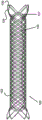
Some embodiments of the present invention engage with stents having loops at their ends (and particularly their proximal ends). For example, fig. 1 shows a stent 100 woven from one or more wires 102 to have a plurality of larger flared loops 104 and smaller secondary loops 107. The flared rings 104 may also have coils 106 and may be connected to radiopaque wires 105 that extend along the length of the stent 100. In another example, fig. 2 shows a double-layered stent 120 having an outer layer 100 and an inner layer 122 similar to fig. 1, the inner layer 122 being woven from a relatively smaller diameter wire 124 than the wire 102. These layers 100 and 122 are connected to each other at a location proximal or along the length of the stent 120 via a connector member 126. Additional details of these stents 100 or 120 can be found in U.S. patent publication nos. 2012/0259404 and 2013/0245745, which are incorporated herein in their entirety.
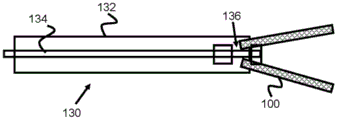
Fig. 3 and 4 show basic cross-sectional views of the delivery system 130 to illustrate the basic operation of the stent engagement and retention mechanisms disclosed in this specification. A stent engagement and retention mechanism 136 is located on the distal end of pusher 134 within delivery sheath 132. Pusher 134 may be advanced within sheath 132 (or sheath 132 may be retracted) to expose stent 100 and allow it to expand within the patient's vessel. Because the stent engagement mechanism 136 engages the loops 106 of the stent 100 (or other feature of the stent 100), the pusher 134 and the stent 100 can be retracted before the stent 100 is fully deployed (i.e., before the stent 100 is fully withdrawn from the sheath 132 and fully radially expanded).
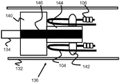
Fig. 5 and 6 relate to one exemplary embodiment of stent engagement mechanism 136, stent engagement mechanism 136 including four protruding struts 142, four protruding struts 142 positioned through ring 104 of stent 100 and operable to pull ring 104 distally before stent 100 is fully deployed. In this regard, stent 100 may be restored back into sheath 132 as long as ring 104 remains positioned around struts 142.
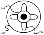
The struts 142 may extend from radially equidistant locations of the tubular center portion 144 and spaced from the distal end of the enlarged push portion 140. In one example, the struts are generally cylindrical and have rounded tops. However, the struts 142 may also be rectangular, square, pyramidal, or the like. The mechanism 136 may include any number of struts 142, such as 1, 2, 3, 4, 5, 6, 7, and 8. Although the struts are disclosed as being positioned along a single radial position, the struts 142 may also be offset from each other by alternating distances or may include multiple rows of struts 142 (e.g., 2, 3, or 4 rows). Offset struts may be used, for example, in systems where some struts hold a larger flared ring of a stent and others hold a smaller secondary ring of a stent.
The strut 142, tubular center portion 144, and enlarged push portion 140 can all be a single unitary member (e.g., all molded as a single piece), or each component can be connected/secured to one another. Pusher 134 and/or the core wire of pusher 134 may be secured within interior channels 146 of portions 140 and 144, allowing pusher 134 to axially move components within sheath 132.
In operation, the distal end of the sheath 132 is positioned at or near a desired deployment location within a vessel. Pusher 134 is advanced distally within sheath 132, causing enlarged push portion 140 to contact the proximal end of ring 104 and push stent 100 distally out of sheath 132. Just before struts 142 exit the distal end of sheath 132, pusher 134 can be withdrawn proximally, causing struts 142 to contact and pull toward the inner proximal portion of loop 104, thereby pulling stent 100 back into sheath 132 for a subsequent deployment attempt.
Fig. 7 illustrates another exemplary embodiment of a stent engagement mechanism 137 that is generally similar to the mechanism 136 described previously, but includes distally-angled struts 143 (i.e., distally-angled ends of struts 143) that can allow loops 104 of stent 100 to more easily slide off and disengage mechanism 137 during final deployment. In one example, the struts 143 can be angled between about 90 degrees and about 45 degrees relative to the surface of the tubular center portion 144. In alternative exemplary embodiments, one or more of the struts 143 may be angled differently (e.g., some struts are angled at 45 degrees and others are angled at 60 degrees). In another alternative exemplary embodiment, struts 143 may be angled proximally at a similar angle to that described above to better retain loop 104 of stent 100 during retraction.
Fig. 8 and 9 illustrate another exemplary embodiment of a stent engagement mechanism 150 that includes a retention block 154, the retention block 154 having a plurality of axially elongated rectangles 154A that are sized to engage the loops 104 of the stent 100. For example, the retention block 154 in FIG. 9 includes four rectangular shapes 154A, but 1-20 (or more) shapes 154A are also possible. The retention block 154 is preferably fixed distally and away from the cylindrical pusher block 152, both connected to a core wire 156 of the pusher. The pusher block 152 is also preferably constructed of a radiopaque material to serve as a visually distinct marker band. In operation, the retaining block 154 and the pushing block 152 function similarly to the previously described embodiments, pulling and pushing, respectively, the loop 104 of the stent 100 through the sheath 132.
Fig. 10-15 relate to yet another stent engagement mechanism 161 that can be secured to pusher 134 and used to retract stent 100 into sheath 132 prior to full deployment. Specifically, the stent retention mechanism 161 includes a tubular body 160 secured to the end of the pusher 134 and can engage and disengage the loops 104 of the stent 100 by closing when inside the sheath 132 and opening when outside the sheath 132. The distal end of the tubular body 160 includes a plurality of elongate channels 160B that extend proximally and then widen into an enlarged channel portion 160C. These channels 160B and 160C effectively form an axially elongated distal finger portion 160A from the tubular body portion 160. In one example, the tubular body 160 includes four symmetrical radially equidistant channels 160B, 160C corresponding to the location of at least some of the rings 104 of the stent 100. However, additional channels may be created to correspond to the loops 104 (e.g., 6 or 8) of the stent 100.
In one embodiment, fingers 160A are heat set to expand radially when unconstrained, as shown in FIGS. 14 and 15. In other embodiments, the finger portions are engaged or bendable such that the radially expandable force of the stent 100 expands against and radially expands the fingers 160A. It should be noted that the closer enlarged passage portion 160C is to the place of deployment, the slower expansion and deployment of stent 100 may occur as stent 100 is pushed distally outward. In addition, further proximal positioning may increase the holding strength of the mechanism 161.
In its compressed configuration, the proximal end or bend of the loop 104 of the stent 100 is located in the enlarged channel portion 160C, and the relatively straight adjacent portions of the loop 104 extend distally above and below the channel portion 160B. Since the enlarged channel portion 160C has a width large enough to accommodate the proximal portion of the loop 104 of the stent 100, but the narrower elongate channel portion 160B is too narrow for the width of the loop 104 when in its compressed configuration, the loop 104, and thus the stent 100, remains engaged with the tubular body 160 when compressed within the sheath 132, as shown in fig. 12 and 13.
The mechanism 161 may be manufactured in various ways to form radially expandable fingers. In one embodiment, a material having a diameter similar to the diameter of the mechanism is placed within the mechanism. The progressively larger diameter material is then introduced into the mechanism and the mechanism is heat set over time. In this manner, the shape memory is built into the fingers of the mechanism, allowing the fingers to expand when unconstrained by a sheath or catheter.
As pusher 134 is advanced distally through sheath 132 and stent 100 is pushed out of the distal end of sheath 132, fingers 160A of tubular body 160 maintain their radially compressed configuration, thereby retaining stent 100. However, when the distal end of the tubular body 160, and thus the finger portions 160A, extend beyond the distal end of the sheath 132, the finger portions 160A radially expand, thereby increasing the width of the elongate channel 160B, as shown in FIGS. 14 and 15, allowing the ring 104 to pass distally through the channel 160B and be released. Thus, until finger portions 160A clear the distal end of sheath 132, stent 100 may be restored and withdrawn into sheath 132 for later deployment.
U.S. patent publications 2010/0268204 and 2015/0289879 describe in detail thermal separation systems that can also be used with the previously described engagement mechanism 161 (or any other embodiment of this specification) and are hereby incorporated by reference in their entirety. In one embodiment, a filament (polymer or metal) or suture may be wrapped between the channels 160C of the tubular body 160 and released similar to the stent ring 104.
Alternatively, a portion of the stent 100 may be placed over the channel 160C and a filament or suture may be used to hold the stent 100 over the channel. The tension applied by the filaments and/or sutures will maintain the tubular body 160 in the closed configuration until ruptured, whereupon the portion will expand to its pre-set expanded shape. A separation system, such as the mechanical system or thermal separation system incorporated above, may be used to break the retaining mechanism of the filament/suture or mesh to remove the retaining force and allow the fingers 160A to expand. Such a configuration may be desirable in situations where a user may wish to have more control over deployment.
While the previously described stent engagement mechanisms may releasably interlock with the loops 104 of the stent 100, other engagement mechanisms may interlock with the retaining arms on the proximal end of the stent 100. For example, FIG. 16 shows a stent 170, the stent 170 having elongated arms 162A/162B secured to the ring 104 extending proximally and terminating in an enlarged area or rounded portion 164. These proximally extending arms 162A/162B and rounded portion 164 allow the engagement mechanism to engage a proximal region spaced from the body of stent 170, thereby allowing stent 170 to expand almost completely without being released from pusher 134.
Fig. 17 illustrates one such stent engagement mechanism, which includes a tubular body 180 that may be secured to the distal end of pusher 134. Similar to the previous embodiments, the tubular body 180 includes a distal end having a plurality of channels. The channel preferably includes a narrower width distal portion 180B and a relatively wider proximal portion 180C that terminates the channel. The wider proximal portion of channel 180C is sized to allow circular portion 164 to enter therein, while the narrower width channel portion 180B may accommodate at least some of arms 162A/162B while being accommodated in sheath 132. The finger portion 180A formed by the channel is preferably connected to a cylindrical support and a radiopaque marker member 182 through which a core wire or guidewire of the pusher 132 may pass.
Similar to the previous embodiment, the stent 170 may still be withdrawn into the sheath 132 after the majority of the endovascular deployment, as long as the finger portions 180A and the wider channel portions 180C remain in the sheath 132. However, once pusher 134 is advanced out of the distal end of sheath 132, arms 162A and 162B expand radially outward, pulling rounded portion 164 out of wider proximal portion 180C of tubular body 180 to fully release stent 100.
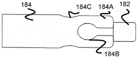
Fig. 18 and 19 illustrate a tubular member 184 that is substantially similar in function and operation to the tubular member 180 previously described. However, tubular member 184 includes some wider channel portion 184B closer to the distal end of tubular member 184, and some wider channel portion 184C proximal to channel portion 184B. In this regard, the stent 170 may include relatively longer arms 162A extending from some of the rings 104 to fit into the proximal channel portion 184C and engage the proximal channel portion 184C, and relatively shorter arms 162B extending from other rings 104 to fit into the distal channel portion 184B and engage the distal channel portion 184B. By offsetting the channel portions 184B and 184C, additional radial space may additionally be obtained, thereby allowing a greater number of channels to be used, if possible.
In one example, the length of the arms 162A/162B may circumferentially alternate between shorter arms 162B and longer arms 162A, while the distal and proximal channel portions 184B/184C may similarly alternate. In one embodiment, the distal channel portions 184B are located on opposite sides of the tubular member 184 from one another, and the proximal channel portions 184C are similarly located on opposite sides of the tubular member 184 from one another, all radially separated from one another by an equal amount. As in the previous embodiment, finger portion 184A is connected to distal support cylinder 182 that allows passage of the core wire of pusher member 134, and may also serve as a radiopaque marker.
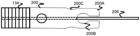
Fig. 20 and 21 illustrate another embodiment of a tubular member 200 similar to the tubular member 184 previously described, having a wider proximal channel portion 200C and a wider distal channel portion 200B. However, the absence of the distal support cylinder 182 allows the distal end of the finger portion 200A to be free.
In one embodiment, the fingers 200A remain in their radial position as they exit the distal end of the sheath 132, maintaining the size of the distal and proximal channels 200B, 200C. In another embodiment, the fingers 200A are heat set to expand radially and thus remain radially compressed when positioned in the sheath 132 and open radially or "flower" when moved outside of the sheath 132. Once radially opened, the size of the distal and proximal passageways 200B, 200C also increases, making the rounded portion 164 easier to release.
As in the previous embodiment with a tubular member, the core wire 206 of the sheath 134 is positioned through the tubular member 200 and extends further distally to the distal end of the stent 100. This positioning allows the stent 100 to be compressed on the core wire 206 and may provide additional friction to assist in pulling the stent 100 out of the sheath 134.
Fig. 22 illustrates another embodiment of a stent engagement mechanism 210 in which a retaining wire 214 passes through at least some of the loops 104 of the stent 100 and is releasably connected to the distal portion 212 of the pusher 234. One end of retaining wire 214 is welded or bonded to distal portion 212 of pusher 234 along location 217. The opposite end of the retaining wire 214 includes an enlarged circular portion 216 that fits within a hole or recess 212A on the distal portion 212.
When in the sheath 132, the rounded portion 216 is retained in the notch 212A, thereby retaining the retaining wire 214 in a closed loop through the stent ring 104. In this regard, the stent 100 may be fully or nearly fully deployed from the sheath 132 and then retracted into the sheath 132 for later re-deployment. Once the desired position of stent 100 is reached, pusher 134 may be further advanced distally such that distal portion 212 and recess 213A are exposed outside of sheath 132. This position allows the rounded portion 216 to move out of the notch 212A, opening the loop formed by the retaining wire 214. Pusher 134 may be withdrawn proximally, pulling retaining wire 214 back into sheath 132.
Although only one retaining wire 214 and notch 216 are shown in fig. 22, a plurality (e.g., 2-6) may be included. These multiple retaining wires 214 may pass through different loops 104 or all the same loops 104. The retaining wire 214 may be constructed of a metal such as nitinol and may be heat set to straighten or may have a flexural rigidity and generally straighten when unconstrained.
Fig. 23 shows yet another embodiment of a stent engagement mechanism 220 having a plurality of pusher flag bands 228 that may be used to contact and pull the flag coils 106 on the stent ring 104, thereby pulling the stent 100 back into the sheath 132. The pusher marker band 228 may be secured over the wire 224 attached at the proximal marker band 221 and the distal adhesive location 226 (e.g., marker band or weld) and bent (bent or bowed) away from the core wire 222 of the pusher 134. Because the marker band 228 "floats" relative to the core wire 222 (or, alternatively, the guidewire), relatively more freedom of movement of the marker band 228 (as opposed to a static clamp directly coupled to the core wire 222) may be provided, and may thereby provide better engagement with the marker coil 106 of the stent ring 104.
Two wires 224 are shown in fig. 23, but any number of wires 224 (e.g., 1-8) corresponding to marker coils 106 may be used. Each thread 224 may include any number of marker bands 228, such as 1-4 bands. Proximal marker band 221 may be formed of a tube, wound coil, or similar structure and, as pusher 134 is advanced distally, pushes the proximal end of ring 104 to push stent 100 out of sheath 132.
As with the previous embodiments, the stent 100 may be almost completely deployed out of the sheath 132 and retracted into the sheath 132. Specifically, if the proximal end of the stent 100 is held in compression so that the marker coil 106 can still contact the marker band 228, the retraction pusher 134 will cause the proximal end of the marker band 228 to contact the distal end of the marker coil 106, thereby pulling the stent 100 proximally within the sheath 138 for later re-deployment.
Fig. 24 shows a stent engagement mechanism 230 that is nearly identical to the previously described mechanism 220. However, instead of using arcuate wires 224 connected at proximal and distal locations, the wires 225 are connected only at the proximal marker bands 221 and extend radially outward. The marker band 228 is located at or near the distal end of the wire 225 and is thus radially spaced from the core wire 222. In this regard, the marker band 228 is positioned in a position similar to the embodiment of fig. 23 to allow contact with the marker coil 106 of the stent 100 when the pusher 134 is retracted proximally. Again, only two wires 225 are shown in fig. 24, but multiple wires are possible (e.g., between 2-8 wires).
Fig. 25 and 26 show a braided stent 230 that is braided to have a relatively large single proximal loop 232 that allows the stent 230 to be fully deployed from the sheath 132 and then retracted into the sheath 132. Preferably, the stent 230 is wire welded at the ends to two symmetrically curved wires 234A and 234B to form an angled proximal end that terminates proximally in a "V" ring 232. The two wires 234A and 234B are preferably welded to each other only at the proximal-most end of the stent 230 and not near the opposite end of the stent top, which allows the loop formed by the wires 234A, 234B to fold more easily within the sheath 134. The proximal ring stent 230 provides spaced apart proximal rings 232 that can be connected to many stent engagement mechanisms previously discussed in this specification, such as mechanism 210.
The two wires 234A and 234B may have a larger diameter than the other wires that make up the stent 230, thereby increasing the ease with which the wires can be welded together. The two wires 234A and 234B may be separate and apart from the wires woven into the stent body, or may be woven together with other wires along the length of the stent 230. Preferably, the other wires constituting the stent body are welded to the lower sides of the wires 234A and 234B.
In general, unless otherwise indicated, the components of the previously described embodiments may have components that include shape memory permissives, such as nitinol and/or polymers.
Implant delivery system materials were previously described. In some embodiments, the implant delivery system is comprised of multiple tubes or multiple elements secured together. In these embodiments, the material of some portions of the delivery system may be different from the material in other portions. Thus, for example, the more proximal portion of the implant delivery system may utilize a high strength material to enhance the high thrust strength, while the more distal portion of the implant delivery system may utilize a material with high shape memory to increase the "blooming" effect of the radial expansion as shown in fig. 14.
The previously described embodiments of the delivery system may have various diameters to accommodate various stent sizes and catheter sizes. In one example, the delivery system can have a diameter of about 0.005 "to about 0.05".
The implant delivery system of the present specification may be used to deliver a variety of implants, such as various occluders, embolic coils, or other implants, although the term "stent" is used throughout the specification for convenience.
Note that although the term catheter or sheath is occasionally used in the specification to discuss structures using an implant delivery system, the delivery system may be used with a variety of delivery devices, such as hypotubes or other delivery devices. Thus, the implant delivery system may be used to deliver implants by any type of delivery device.
It is noted that the drawings shown are merely representations and/or illustrations helpful for understanding and are not limited to what is explicitly shown. Similarly, any measurements are merely illustrative examples to aid understanding and are not meant to be limiting.
Although the present invention has been described in terms of particular embodiments and applications, those of ordinary skill in the art, in light of this teaching, can generate additional embodiments and modifications without departing from the spirit or exceeding the scope of the claimed invention. Accordingly, it is to be understood that the drawings and descriptions herein are proffered by way of example to facilitate comprehension of the invention and should not be construed to limit the scope thereof.
Claims (10)
1. A vascular implant delivery device, comprising:
a sheath (132);
an elongated pusher (134) disposed within the sheath;
a plurality of wires (224, 225) extending distally from the pusher (134);
a marker band (228) on the plurality of wires;
an implant having a plurality of marker coils (106);
the method is characterized in that:
the plurality of wires support the marker band at a position radially away from a center of the pusher; and
the marker band is located distally of the marker coil within the sheath, and if the proximal end of the implant remains compressed such that the marker coil (106) may still be in contact with the marker band (228), retracting the elongate pusher (134) will cause the proximal end of the marker band (228) to contact the distal end of the marker coil (106), thereby pulling the implant proximally within the sheath (138).
2. The vascular implant delivery device according to claim 1, wherein the plurality of wires (224, 225) are bent away from the pusher.
3. The vascular implant delivery device according to claim 1, wherein the plurality of wires (224, 225) are arcuate.
4. The vascular implant delivery device according to claim 1, further comprising a distal engagement location (226), said distal engagement location (226) comprising a marker band at a distal end of said pusher (134).
5. The vascular implant delivery device according to claim 1, wherein the plurality of wires (224, 225) extending distally from the pusher comprises 2 to 8 wires.
6. The vascular implant delivery device according to claim 1, further comprising a core wire (222).
7. The vascular implant delivery device according to claim 6, wherein the plurality of wires are connected proximally to the pusher and distally to a distal bond site (226) on the core wire (222).
8. The vascular implant delivery apparatus according to claim 7, wherein the distal bond site (226) is a marker band or a weld.
9. The vascular implant delivery device according to claim 1, wherein the marker coil (106) protrudes radially from a proximal ring (104) of the implant.
10. The vascular implant delivery device of claim 1, wherein the marker bands are flush with the distal ends of the plurality of wires.
Applications Claiming Priority (3)
| Application Number | Priority Date | Filing Date | Title |
|---|---|---|---|
| US201562220910P | 2015-09-18 | 2015-09-18 | |
| US62/220,910 | 2015-09-18 | ||
| PCT/US2016/052539 WO2017049312A1 (en) | 2015-09-18 | 2016-09-19 | Releasable delivery system |
Publications (2)
| Publication Number | Publication Date |
|---|---|
| CN108260342A CN108260342A (en) | 2018-07-06 |
| CN108260342B true CN108260342B (en) | 2021-07-30 |
Family
ID=58276409
Family Applications (1)
| Application Number | Title | Priority Date | Filing Date |
|---|---|---|---|
| CN201680064425.6A Active CN108260342B (en) | 2015-09-18 | 2016-09-19 | Releasable delivery system |
Country Status (5)
| Country | Link |
|---|---|
| US (4) | US10182931B2 (en) |
| EP (1) | EP3349670B1 (en) |
| JP (1) | JP6816126B2 (en) |
| CN (1) | CN108260342B (en) |
| WO (1) | WO2017049312A1 (en) |
Families Citing this family (166)
| Publication number | Priority date | Publication date | Assignee | Title |
|---|---|---|---|---|
| CA2625826C (en) | 2005-10-19 | 2014-08-05 | Pulsar Vascular, Inc. | Methods and systems for endovascularly clipping and repairing lumen and tissue defects |
| US9402707B2 (en) | 2008-07-22 | 2016-08-02 | Neuravi Limited | Clot capture systems and associated methods |
| KR101652804B1 (en) | 2008-09-05 | 2016-08-31 | 펄사 배스큘라, 아이엔씨. | Systems and methods for supporting or occluding a physiological opening or cavity |
| US9463036B2 (en) | 2010-10-22 | 2016-10-11 | Neuravi Limited | Clot engagement and removal system |
| US9301769B2 (en) | 2011-03-09 | 2016-04-05 | Neuravi Limited | Clot retrieval device for removing clot from a blood vessel |
| US12076037B2 (en) | 2011-03-09 | 2024-09-03 | Neuravi Limited | Systems and methods to restore perfusion to a vessel |
| US11259824B2 (en) | 2011-03-09 | 2022-03-01 | Neuravi Limited | Clot retrieval device for removing occlusive clot from a blood vessel |
| CN103582460B (en) | 2011-06-03 | 2019-03-19 | 帕尔萨维斯库勒公司 | Aneurysm devices and related systems and methods with additional anchoring mechanism |
| US9119625B2 (en) | 2011-10-05 | 2015-09-01 | Pulsar Vascular, Inc. | Devices, systems and methods for enclosing an anatomical opening |
| US9439791B2 (en) | 2012-03-16 | 2016-09-13 | Microvention, Inc. | Stent and stent delivery device |
| US10561509B2 (en) | 2013-03-13 | 2020-02-18 | DePuy Synthes Products, Inc. | Braided stent with expansion ring and method of delivery |
| US10603157B2 (en) | 2013-03-13 | 2020-03-31 | DePuy Synthes Products, Inc. | Braid implant delivery and retraction device with distal engagement |
| US9433429B2 (en) | 2013-03-14 | 2016-09-06 | Neuravi Limited | Clot retrieval devices |
| TR201901830T4 (en) | 2013-03-14 | 2019-03-21 | Neuravi Ltd | Devices and methods for the removal of acute blockages from blood vessels. |
| CN105208950A (en) | 2013-03-14 | 2015-12-30 | 尼尔拉维有限公司 | A clot retrieval device for removing occlusive clot from a blood vessel |
| US9265512B2 (en) | 2013-12-23 | 2016-02-23 | Silk Road Medical, Inc. | Transcarotid neurovascular catheter |
| US10285720B2 (en) | 2014-03-11 | 2019-05-14 | Neuravi Limited | Clot retrieval system for removing occlusive clot from a blood vessel |
| US11076860B2 (en) | 2014-03-31 | 2021-08-03 | DePuy Synthes Products, Inc. | Aneurysm occlusion device |
| US11154302B2 (en) | 2014-03-31 | 2021-10-26 | DePuy Synthes Products, Inc. | Aneurysm occlusion device |
| EP3154452B1 (en) | 2014-06-13 | 2024-09-18 | Neuravi Limited | Devices for removal of acute blockages from blood vessels |
| US10265086B2 (en) | 2014-06-30 | 2019-04-23 | Neuravi Limited | System for removing a clot from a blood vessel |
| US9918718B2 (en) | 2014-08-08 | 2018-03-20 | DePuy Synthes Products, Inc. | Embolic coil delivery system with retractable mechanical release mechanism |
| US10206796B2 (en) | 2014-08-27 | 2019-02-19 | DePuy Synthes Products, Inc. | Multi-strand implant with enhanced radiopacity |
| US9782178B2 (en) | 2014-09-19 | 2017-10-10 | DePuy Synthes Products, Inc. | Vasculature occlusion device detachment system with tapered corewire and heater activated fiber detachment |
| US10617435B2 (en) | 2014-11-26 | 2020-04-14 | Neuravi Limited | Clot retrieval device for removing clot from a blood vessel |
| US11253278B2 (en) | 2014-11-26 | 2022-02-22 | Neuravi Limited | Clot retrieval system for removing occlusive clot from a blood vessel |
| WO2016083472A1 (en) | 2014-11-26 | 2016-06-02 | Neuravi Limited | A clot retrieval device for removing occlusive clot from a blood vessel |
| US11065019B1 (en) | 2015-02-04 | 2021-07-20 | Route 92 Medical, Inc. | Aspiration catheter systems and methods of use |
| EP3253437B1 (en) | 2015-02-04 | 2019-12-04 | Route 92 Medical, Inc. | Rapid aspiration thrombectomy system |
| WO2017019563A1 (en) | 2015-07-24 | 2017-02-02 | Route 92 Medical, Inc. | Anchoring delivery system and methods |
| WO2017147493A1 (en) | 2016-02-24 | 2017-08-31 | Incept, Llc | Enhanced flexibility neurovascular catheter |
| US10285710B2 (en) | 2016-06-01 | 2019-05-14 | DePuy Synthes Products, Inc. | Endovascular detachment system with flexible distal end and heater activated detachment |
| KR102457315B1 (en) | 2016-08-17 | 2022-10-24 | 뉴라비 리미티드 | A thrombus recovery system to remove an occlusive thrombus from a blood vessel |
| US10076428B2 (en) | 2016-08-25 | 2018-09-18 | DePuy Synthes Products, Inc. | Expansion ring for a braided stent |
| EP3509509B1 (en) | 2016-09-06 | 2021-03-31 | Neuravi Limited | A clot retrieval device for removing occlusive clot from a blood vessel |
| US10292851B2 (en) | 2016-09-30 | 2019-05-21 | DePuy Synthes Products, Inc. | Self-expanding device delivery apparatus with dual function bump |
| US10517708B2 (en) | 2016-10-26 | 2019-12-31 | DePuy Synthes Products, Inc. | Multi-basket clot capturing device |
| US10653426B2 (en) | 2017-01-06 | 2020-05-19 | Incept, Llc | Thromboresistant coatings for aneurysm treatment devices |
| WO2018132387A1 (en) | 2017-01-10 | 2018-07-19 | Route 92 Medical, Inc. | Aspiration catheter systems and methods of use |
| US10905853B2 (en) | 2017-01-17 | 2021-02-02 | DePuy Synthes Products, Inc. | System and method for delivering a catheter |
| US10881497B2 (en) | 2017-01-26 | 2021-01-05 | DePuy Synthes Products, Inc. | Composite vascular flow diverter |
| WO2018156833A1 (en) | 2017-02-23 | 2018-08-30 | DePuy Synthes Products, Inc. | Aneurysm device and delivery system |
| US11051824B2 (en) * | 2017-09-28 | 2021-07-06 | Microvention, Inc. | Embolic delivery |
| US10806462B2 (en) | 2017-12-21 | 2020-10-20 | DePuy Synthes Products, Inc. | Implantable medical device detachment system with split tube and cylindrical coupling |
| US10751065B2 (en) | 2017-12-22 | 2020-08-25 | DePuy Synthes Products, Inc. | Aneurysm device and delivery system |
| US10905430B2 (en) | 2018-01-24 | 2021-02-02 | DePuy Synthes Products, Inc. | Aneurysm device and delivery system |
| US11471310B2 (en) | 2018-03-19 | 2022-10-18 | SB-Kawasumi Laboratories, Inc. | Indwelling device and cylindrical treatment tool |
| US10786259B2 (en) | 2018-03-30 | 2020-09-29 | DePuy Synthes Products, Inc. | Split balloon assist device and method for using the same |
| US10918390B2 (en) | 2018-03-30 | 2021-02-16 | DePuy Synthes Products, Inc. | Helical balloon assist device and method for using the same |
| US10806461B2 (en) | 2018-04-27 | 2020-10-20 | DePuy Synthes Products, Inc. | Implantable medical device detachment system with split tube |
| CN112203593A (en) | 2018-05-01 | 2021-01-08 | 因赛普特有限责任公司 | Device and method for removing occlusive material from an intravascular site |
| US11395665B2 (en) | 2018-05-01 | 2022-07-26 | Incept, Llc | Devices and methods for removing obstructive material, from an intravascular site |
| CN115920204A (en) | 2018-05-17 | 2023-04-07 | 92号医疗公司 | Aspiration catheter system and method of use |
| US11058430B2 (en) | 2018-05-25 | 2021-07-13 | DePuy Synthes Products, Inc. | Aneurysm device and delivery system |
| US11596412B2 (en) | 2018-05-25 | 2023-03-07 | DePuy Synthes Products, Inc. | Aneurysm device and delivery system |
| US10939915B2 (en) | 2018-05-31 | 2021-03-09 | DePuy Synthes Products, Inc. | Aneurysm device and delivery system |
| US10667833B2 (en) | 2018-06-08 | 2020-06-02 | Neuravi Limited | Guidewire with an atraumatic clot-circumventing configured distal end for use in an endovascular medical system |
| US10898216B2 (en) | 2018-06-13 | 2021-01-26 | DePuy Synthes Products, Inc. | Vasculature obstruction capture device |
| US11471582B2 (en) | 2018-07-06 | 2022-10-18 | Incept, Llc | Vacuum transfer tool for extendable catheter |
| US11517335B2 (en) | 2018-07-06 | 2022-12-06 | Incept, Llc | Sealed neurovascular extendable catheter |
| CN112423710A (en) * | 2018-07-18 | 2021-02-26 | W.L.戈尔及同仁股份有限公司 | Implantable medical device deployment system |
| AU2019204522A1 (en) | 2018-07-30 | 2020-02-13 | DePuy Synthes Products, Inc. | Systems and methods of manufacturing and using an expansion ring |
| US10905431B2 (en) | 2018-08-03 | 2021-02-02 | DePuy Synthes Products, Inc. | Spiral delivery system for embolic braid |
| US10278848B1 (en) | 2018-08-06 | 2019-05-07 | DePuy Synthes Products, Inc. | Stent delivery with expansion assisting delivery wire |
| US10456280B1 (en) | 2018-08-06 | 2019-10-29 | DePuy Synthes Products, Inc. | Systems and methods of using a braided implant |
| US11051825B2 (en) | 2018-08-08 | 2021-07-06 | DePuy Synthes Products, Inc. | Delivery system for embolic braid |
| US10813780B2 (en) | 2018-08-08 | 2020-10-27 | DePuy Synthes Products, Inc. | Intraluminal implant delivery system and method |
| WO2020046364A1 (en) * | 2018-08-31 | 2020-03-05 | W. L. Gore & Associates, Inc. | Apparatus, system, and method for steering an implantable medical device |
| US10842498B2 (en) | 2018-09-13 | 2020-11-24 | Neuravi Limited | Systems and methods of restoring perfusion to a vessel |
| JP2020044335A (en) | 2018-09-20 | 2020-03-26 | デピュイ・シンセス・プロダクツ・インコーポレイテッド | Stent with shaped wire |
| US11123077B2 (en) | 2018-09-25 | 2021-09-21 | DePuy Synthes Products, Inc. | Intrasaccular device positioning and deployment system |
| US11406416B2 (en) | 2018-10-02 | 2022-08-09 | Neuravi Limited | Joint assembly for vasculature obstruction capture device |
| US11253287B2 (en) | 2018-10-04 | 2022-02-22 | Neuravi Limited | Retrograde blood flow occlusion flushing device |
| AU2019355984B2 (en) * | 2018-10-05 | 2022-09-08 | W. L. Gore & Associates, Inc. | Constraining mechanisms and associated methods |
| US11076861B2 (en) | 2018-10-12 | 2021-08-03 | DePuy Synthes Products, Inc. | Folded aneurysm treatment device and delivery method |
| US11147562B2 (en) | 2018-12-12 | 2021-10-19 | DePuy Synthes Products, Inc. | Systems and methods for embolic implant detachment |
| US11406392B2 (en) | 2018-12-12 | 2022-08-09 | DePuy Synthes Products, Inc. | Aneurysm occluding device for use with coagulating agents |
| US11272939B2 (en) | 2018-12-18 | 2022-03-15 | DePuy Synthes Products, Inc. | Intrasaccular flow diverter for treating cerebral aneurysms |
| US11039944B2 (en) | 2018-12-27 | 2021-06-22 | DePuy Synthes Products, Inc. | Braided stent system with one or more expansion rings |
| US11134953B2 (en) | 2019-02-06 | 2021-10-05 | DePuy Synthes Products, Inc. | Adhesive cover occluding device for aneurysm treatment |
| US11273285B2 (en) | 2019-02-07 | 2022-03-15 | DePuy Synthes Products, Inc. | Ancillary device for detaching implants |
| ES2910600T3 (en) | 2019-03-04 | 2022-05-12 | Neuravi Ltd | Powered Clot Recovery Catheter |
| US11382633B2 (en) | 2019-03-06 | 2022-07-12 | DePuy Synthes Products, Inc. | Strut flow diverter for cerebral aneurysms and methods for preventing strut entanglement |
| CN113825475A (en) * | 2019-03-13 | 2021-12-21 | 微仙美国有限公司 | Stent and stent delivery |
| US11337706B2 (en) | 2019-03-27 | 2022-05-24 | DePuy Synthes Products, Inc. | Aneurysm treatment device |
| US11185334B2 (en) | 2019-03-28 | 2021-11-30 | DePuy Synthes Products, Inc. | Single lumen reduced profile occlusion balloon catheter |
| US11766539B2 (en) | 2019-03-29 | 2023-09-26 | Incept, Llc | Enhanced flexibility neurovascular catheter |
| US11051928B2 (en) | 2019-04-11 | 2021-07-06 | Neuravi Limited | Floating carotid filter |
| US11957855B2 (en) | 2019-05-09 | 2024-04-16 | Neuravi Limited | Balloon guide catheter with positive venting of residual air |
| US11931522B2 (en) | 2019-05-09 | 2024-03-19 | Neuravi Limited | Inflation lumen kink protection and balloon profile |
| US11571553B2 (en) | 2019-05-09 | 2023-02-07 | Neuravi Limited | Balloon guide catheter with thermally expandable material |
| US11607531B2 (en) | 2019-05-09 | 2023-03-21 | Neuravi Limited | Balloon catheter with venting of residual air in a proximal direction |
| USD959659S1 (en) | 2019-05-10 | 2022-08-02 | DePuy Synthes Products, Inc. | Implant release handle |
| US11413046B2 (en) | 2019-05-21 | 2022-08-16 | DePuy Synthes Products, Inc. | Layered braided aneurysm treatment device |
| US11602350B2 (en) | 2019-12-05 | 2023-03-14 | DePuy Synthes Products, Inc. | Intrasaccular inverting braid with highly flexible fill material |
| US11607226B2 (en) | 2019-05-21 | 2023-03-21 | DePuy Synthes Products, Inc. | Layered braided aneurysm treatment device with corrugations |
| US11672542B2 (en) | 2019-05-21 | 2023-06-13 | DePuy Synthes Products, Inc. | Aneurysm treatment with pushable ball segment |
| US11278292B2 (en) | 2019-05-21 | 2022-03-22 | DePuy Synthes Products, Inc. | Inverting braided aneurysm treatment system and method |
| US11497504B2 (en) | 2019-05-21 | 2022-11-15 | DePuy Synthes Products, Inc. | Aneurysm treatment with pushable implanted braid |
| US10653425B1 (en) | 2019-05-21 | 2020-05-19 | DePuy Synthes Products, Inc. | Layered braided aneurysm treatment device |
| US11406403B2 (en) | 2019-06-14 | 2022-08-09 | Neuravi Limited | Visibility of mechanical thrombectomy device during diagnostic imaging |
| US11109939B2 (en) | 2019-06-14 | 2021-09-07 | DePuy Synthes Products, Inc. | Intravascular devices with radiopaque body markers |
| US11253265B2 (en) | 2019-06-18 | 2022-02-22 | DePuy Synthes Products, Inc. | Pull wire detachment for intravascular devices |
| CN110151368A (en) * | 2019-06-28 | 2019-08-23 | 微创神通医疗科技(上海)有限公司 | Vascular implant, conveying device and Medical Devices |
| US11426174B2 (en) | 2019-10-03 | 2022-08-30 | DePuy Synthes Products, Inc. | Medical device delivery member with flexible stretch resistant mechanical release |
| US11207494B2 (en) | 2019-07-03 | 2021-12-28 | DePuy Synthes Products, Inc. | Medical device delivery member with flexible stretch resistant distal portion |
| US11266426B2 (en) | 2019-07-10 | 2022-03-08 | DePuy Synthes Products, Inc. | Streamlined treatment of clot removal, angioplasty and prevention of restenosis using a single integrated intravascular device |
| US11266427B2 (en) | 2019-07-10 | 2022-03-08 | Neuravi Limited | Self-expanding intravascular medical device |
| US11395675B2 (en) | 2019-07-11 | 2022-07-26 | DePuy Synthes Products, Inc. | Clot retriever cleaning for reinsertion |
| JP2021041169A (en) | 2019-09-11 | 2021-03-18 | ニューラヴィ・リミテッド | Expandable mouth catheter |
| US11439403B2 (en) | 2019-09-17 | 2022-09-13 | DePuy Synthes Products, Inc. | Embolic coil proximal connecting element and stretch resistant fiber |
| WO2021076642A1 (en) | 2019-10-15 | 2021-04-22 | Imperative Care, Inc. | Systems and methods for multivariate stroke detection |
| US11712231B2 (en) | 2019-10-29 | 2023-08-01 | Neuravi Limited | Proximal locking assembly design for dual stent mechanical thrombectomy device |
| CN114901219A (en) | 2019-11-12 | 2022-08-12 | 微仙美国有限公司 | Stent delivery system and method |
| US11376013B2 (en) | 2019-11-18 | 2022-07-05 | DePuy Synthes Products, Inc. | Implant delivery system with braid cup formation |
| US11628282B2 (en) | 2019-11-25 | 2023-04-18 | Neuravi Limited | No preparation balloon guide catheter |
| US11839725B2 (en) | 2019-11-27 | 2023-12-12 | Neuravi Limited | Clot retrieval device with outer sheath and inner catheter |
| US11779364B2 (en) | 2019-11-27 | 2023-10-10 | Neuravi Limited | Actuated expandable mouth thrombectomy catheter |
| US11517340B2 (en) | 2019-12-03 | 2022-12-06 | Neuravi Limited | Stentriever devices for removing an occlusive clot from a vessel and methods thereof |
| EP4076611A4 (en) | 2019-12-18 | 2023-11-15 | Imperative Care, Inc. | Methods and systems for treating venous thromboembolic disease |
| US11638637B2 (en) | 2019-12-18 | 2023-05-02 | Imperative Care, Inc. | Method of removing embolic material with thrombus engagement tool |
| US20210315598A1 (en) | 2019-12-18 | 2021-10-14 | Imperative Care, Inc. | Methods of placing large bore aspiration catheters |
| US11457926B2 (en) | 2019-12-18 | 2022-10-04 | DePuy Synthes Products, Inc. | Implant having an intrasaccular section and intravascular section |
| US11457922B2 (en) | 2020-01-22 | 2022-10-04 | DePuy Synthes Products, Inc. | Medical device delivery member with flexible stretch resistant distal portion |
| US11992241B2 (en) | 2020-01-31 | 2024-05-28 | DePuy Synthes Products, Inc. | System to assist delivery of a mechanical intravascular treatment device |
| US11957354B2 (en) | 2020-02-10 | 2024-04-16 | DePuy Synthes Products, Inc. | Aneurysm implant support device |
| US11432822B2 (en) | 2020-02-14 | 2022-09-06 | DePuy Synthes Products, Inc. | Intravascular implant deployment system |
| US11944327B2 (en) | 2020-03-05 | 2024-04-02 | Neuravi Limited | Expandable mouth aspirating clot retrieval catheter |
| US11504254B2 (en) | 2020-03-05 | 2022-11-22 | Fluid Biomed Inc. | System and methods for compressing endovascular devices |
| US11633198B2 (en) | 2020-03-05 | 2023-04-25 | Neuravi Limited | Catheter proximal joint |
| EP4117762A4 (en) | 2020-03-10 | 2024-05-08 | Imperative Care, Inc. | Enhanced flexibility neurovascular catheter |
| US11883043B2 (en) | 2020-03-31 | 2024-01-30 | DePuy Synthes Products, Inc. | Catheter funnel extension |
| US11759217B2 (en) | 2020-04-07 | 2023-09-19 | Neuravi Limited | Catheter tubular support |
| US11730501B2 (en) | 2020-04-17 | 2023-08-22 | Neuravi Limited | Floating clot retrieval device for removing clots from a blood vessel |
| US11717308B2 (en) | 2020-04-17 | 2023-08-08 | Neuravi Limited | Clot retrieval device for removing heterogeneous clots from a blood vessel |
| US11871946B2 (en) | 2020-04-17 | 2024-01-16 | Neuravi Limited | Clot retrieval device for removing clot from a blood vessel |
| US11523831B2 (en) | 2020-04-30 | 2022-12-13 | DePuy Synthes Products, Inc. | Intrasaccular flow diverter |
| US11737771B2 (en) | 2020-06-18 | 2023-08-29 | Neuravi Limited | Dual channel thrombectomy device |
| US11937836B2 (en) | 2020-06-22 | 2024-03-26 | Neuravi Limited | Clot retrieval system with expandable clot engaging framework |
| US11439418B2 (en) | 2020-06-23 | 2022-09-13 | Neuravi Limited | Clot retrieval device for removing clot from a blood vessel |
| US11395669B2 (en) | 2020-06-23 | 2022-07-26 | Neuravi Limited | Clot retrieval device with flexible collapsible frame |
| US11951026B2 (en) | 2020-06-30 | 2024-04-09 | DePuy Synthes Products, Inc. | Implantable medical device detachment system with flexible braid section |
| US11207497B1 (en) | 2020-08-11 | 2021-12-28 | Imperative Care, Inc. | Catheter with enhanced tensile strength |
| US11864781B2 (en) | 2020-09-23 | 2024-01-09 | Neuravi Limited | Rotating frame thrombectomy device |
| US11786698B2 (en) | 2020-12-08 | 2023-10-17 | DePuy Synthes Products, Inc. | Catheter with textured surface |
| US11826520B2 (en) | 2020-12-08 | 2023-11-28 | DePuy Synthes Products, Inc. | Catheter designs for enhanced column strength |
| US12029670B2 (en) | 2020-12-23 | 2024-07-09 | Olympus Corporation | Stent delivery device |
| US11937837B2 (en) | 2020-12-29 | 2024-03-26 | Neuravi Limited | Fibrin rich / soft clot mechanical thrombectomy device |
| CN113288314A (en) * | 2021-01-06 | 2021-08-24 | 微创神通医疗科技(上海)有限公司 | Vascular implant and medical equipment |
| US12029442B2 (en) | 2021-01-14 | 2024-07-09 | Neuravi Limited | Systems and methods for a dual elongated member clot retrieval apparatus |
| WO2022156388A1 (en) * | 2021-01-22 | 2022-07-28 | 江苏暖阳医疗器械有限公司 | Intravascular implant fixation and retention structure, delivery system, and handle-type stent system |
| CN112716666A (en) * | 2021-01-22 | 2021-04-30 | 江苏暖阳医疗器械有限公司 | Handle type bracket system |
| US11872354B2 (en) | 2021-02-24 | 2024-01-16 | Neuravi Limited | Flexible catheter shaft frame with seam |
| US12064130B2 (en) | 2021-03-18 | 2024-08-20 | Neuravi Limited | Vascular obstruction retrieval device having sliding cages pinch mechanism |
| US11974764B2 (en) | 2021-06-04 | 2024-05-07 | Neuravi Limited | Self-orienting rotating stentriever pinching cells |
| US11998213B2 (en) | 2021-07-14 | 2024-06-04 | DePuy Synthes Products, Inc. | Implant delivery with modified detachment feature and pull wire engagement |
| US11937839B2 (en) | 2021-09-28 | 2024-03-26 | Neuravi Limited | Catheter with electrically actuated expandable mouth |
| US12011186B2 (en) | 2021-10-28 | 2024-06-18 | Neuravi Limited | Bevel tip expandable mouth catheter with reinforcing ring |
| US11751881B2 (en) | 2021-11-26 | 2023-09-12 | DePuy Synthes Products, Inc. | Securement wire withstanding forces during deployment of implantable intravascular treatment device using a delivery and detachment system |
| US11844490B2 (en) | 2021-12-30 | 2023-12-19 | DePuy Synthes Products, Inc. | Suture linkage for inhibiting premature embolic implant deployment |
| US11937824B2 (en) | 2021-12-30 | 2024-03-26 | DePuy Synthes Products, Inc. | Implant detachment systems with a modified pull wire |
| US12011171B2 (en) | 2022-01-06 | 2024-06-18 | DePuy Synthes Products, Inc. | Systems and methods for inhibiting premature embolic implant deployment |
| US11937825B2 (en) | 2022-03-02 | 2024-03-26 | DePuy Synthes Products, Inc. | Hook wire for preventing premature embolic implant detachment |
| US11937826B2 (en) | 2022-03-14 | 2024-03-26 | DePuy Synthes Products, Inc. | Proximal link wire for preventing premature implant detachment |
| US20230338175A1 (en) * | 2022-04-26 | 2023-10-26 | Accumedical Beijing Ltd. | Repositionable intracranial stent with retrieval mechanism |
| CN114848073B (en) * | 2022-05-26 | 2024-07-19 | 北京先瑞达医疗科技有限公司 | Internal implant delivery device and delivery system |
Citations (10)
| Publication number | Priority date | Publication date | Assignee | Title |
|---|---|---|---|---|
| EP1326672A1 (en) * | 2000-10-18 | 2003-07-16 | NMT Medical, Inc. | Over-the-wire interlock attachment/detachment mechanism |
| EP1362564A1 (en) * | 2002-05-16 | 2003-11-19 | Cordis Neurovascular, Inc. | Intravascular stent device |
| CN101415459A (en) * | 2004-08-25 | 2009-04-22 | 麦克罗文逊股份有限公司 | Thermal detachment system for implantable devices |
| CN101448464A (en) * | 2006-04-17 | 2009-06-03 | 微治疗公司 | System and method for mechanically positioning intravascular implants |
| US7729738B2 (en) * | 1995-10-13 | 2010-06-01 | Medtronic Vascular, Inc. | Stabilized tissue penetrating catheters |
| WO2011014814A3 (en) * | 2009-07-30 | 2011-03-31 | Boston Scientific Scimed, Inc. | Stent delivery system |
| CN102985034A (en) * | 2010-05-27 | 2013-03-20 | 美敦力瓦斯科尔勒戈尔韦有限公司 | Catheter assembly with prosthesis crimping and prosthesis retaining accessories |
| CN103153214A (en) * | 2010-10-01 | 2013-06-12 | 科维蒂恩有限合伙公司 | Apparatuses for flow restoration and implanting members in the human body |
| CN103635162A (en) * | 2011-06-30 | 2014-03-12 | 库克医学技术有限责任公司 | Spring controlled stent delivery system |
| CN104758098A (en) * | 2009-04-10 | 2015-07-08 | 斯波瑞申有限公司 | Deployment catheter used for deploying medical device and method for deploying medical device |
Family Cites Families (30)
| Publication number | Priority date | Publication date | Assignee | Title |
|---|---|---|---|---|
| US5824041A (en) | 1994-06-08 | 1998-10-20 | Medtronic, Inc. | Apparatus and methods for placement and repositioning of intraluminal prostheses |
| US6776791B1 (en) | 1998-04-01 | 2004-08-17 | Endovascular Technologies, Inc. | Stent and method and device for packing of same |
| US6554848B2 (en) | 2000-06-02 | 2003-04-29 | Advanced Cardiovascular Systems, Inc. | Marker device for rotationally orienting a stent delivery system prior to deploying a curved self-expanding stent |
| US20020016597A1 (en) | 2000-08-02 | 2002-02-07 | Dwyer Clifford J. | Delivery apparatus for a self-expanding stent |
| US6623518B2 (en) | 2001-02-26 | 2003-09-23 | Ev3 Peripheral, Inc. | Implant delivery system with interlock |
| US7001422B2 (en) | 2002-09-23 | 2006-02-21 | Cordis Neurovascular, Inc | Expandable stent and delivery system |
| US20040267348A1 (en) * | 2003-04-11 | 2004-12-30 | Gunderson Richard C. | Medical device delivery systems |
| US7473271B2 (en) * | 2003-04-11 | 2009-01-06 | Boston Scientific Scimed, Inc. | Stent delivery system with securement and deployment accuracy |
| US20070100414A1 (en) * | 2005-11-02 | 2007-05-03 | Cardiomind, Inc. | Indirect-release electrolytic implant delivery systems |
| US8690935B2 (en) * | 2006-04-28 | 2014-04-08 | DePuy Synthes Products, LLC | Stent delivery system with threaded engagement and method |
| DE602007011251D1 (en) * | 2006-05-12 | 2011-01-27 | Ev3 Inc | IMPLANT AND RELEASE SYSTEM WITH SEVERAL MARKER LOCKS |
| US8029558B2 (en) * | 2006-07-07 | 2011-10-04 | Abbott Cardiovascular Systems, Inc. | Stent and catheter assembly and method for treating bifurcations |
| US20080300667A1 (en) | 2007-05-31 | 2008-12-04 | Bay Street Medical | System for delivering a stent |
| US20090287290A1 (en) * | 2008-01-24 | 2009-11-19 | Medtronic, Inc. | Delivery Systems and Methods of Implantation for Prosthetic Heart Valves |
| US8821563B2 (en) * | 2008-10-17 | 2014-09-02 | Cook Medical Technologies Llc | System and method for deploying and positioning an endovascular device |
| US9629719B2 (en) * | 2010-04-23 | 2017-04-25 | Medtronic, Inc. | Delivery systems and methods of implantation for prosthetic heart valves |
| BR112013001024A2 (en) * | 2010-07-15 | 2016-05-24 | St Jude Medical | implantable medical device delivery device, implantable medical device delivery system, and prosthetic valve delivery method |
| DE102010044746A1 (en) * | 2010-09-08 | 2012-03-08 | Phenox Gmbh | Implant for influencing the blood flow in arteriovenous malformations |
| JP2014504171A (en) | 2010-11-15 | 2014-02-20 | エレンザ, インコーポレイテッド | Compatible intraocular lens |
| US9155619B2 (en) * | 2011-02-25 | 2015-10-13 | Edwards Lifesciences Corporation | Prosthetic heart valve delivery apparatus |
| WO2013074662A1 (en) | 2011-11-15 | 2013-05-23 | Boston Scientific Scimed, Inc. | Medical device with one or more sheathing transition members |
| JP5834997B2 (en) | 2012-02-23 | 2015-12-24 | 株式会社ソシオネクスト | Vector processor, vector processor processing method |
| US20130226278A1 (en) | 2012-02-23 | 2013-08-29 | Tyco Healthcare Group Lp | Methods and apparatus for luminal stenting |
| US9405541B2 (en) | 2012-03-16 | 2016-08-02 | International Business Machines Corporation | Run-time instrumentation indirect sampling by address |
| US9439791B2 (en) | 2012-03-16 | 2016-09-13 | Microvention, Inc. | Stent and stent delivery device |
| US9220616B2 (en) * | 2012-04-13 | 2015-12-29 | Medtronic Vascular, Inc. | Stent-graft delivery system having a rotatable single shaft tip capture mechanism |
| US20130289692A1 (en) * | 2012-04-27 | 2013-10-31 | Medtronic Vascular, Inc. | Reconfigurable stent-graft delivery system and method of use |
| US10524909B2 (en) * | 2012-10-12 | 2020-01-07 | St. Jude Medical, Cardiology Division, Inc. | Retaining cage to permit resheathing of a tavi aortic-first transapical system |
| US20140180387A1 (en) * | 2012-12-21 | 2014-06-26 | Stryker Nv Operations Limited | Stent delivery system |
| US9295571B2 (en) * | 2013-01-17 | 2016-03-29 | Covidien Lp | Methods and apparatus for luminal stenting |
-
2016
- 2016-09-19 JP JP2018514324A patent/JP6816126B2/en active Active
- 2016-09-19 EP EP16847564.8A patent/EP3349670B1/en active Active
- 2016-09-19 CN CN201680064425.6A patent/CN108260342B/en active Active
- 2016-09-19 US US15/269,782 patent/US10182931B2/en active Active
- 2016-09-19 WO PCT/US2016/052539 patent/WO2017049312A1/en active Application Filing
-
2019
- 2019-01-10 US US16/244,910 patent/US11000394B2/en active Active
-
2021
- 2021-04-02 US US17/221,641 patent/US11931277B2/en active Active
-
2024
- 2024-02-08 US US18/436,487 patent/US20240173155A1/en active Pending
Patent Citations (10)
| Publication number | Priority date | Publication date | Assignee | Title |
|---|---|---|---|---|
| US7729738B2 (en) * | 1995-10-13 | 2010-06-01 | Medtronic Vascular, Inc. | Stabilized tissue penetrating catheters |
| EP1326672A1 (en) * | 2000-10-18 | 2003-07-16 | NMT Medical, Inc. | Over-the-wire interlock attachment/detachment mechanism |
| EP1362564A1 (en) * | 2002-05-16 | 2003-11-19 | Cordis Neurovascular, Inc. | Intravascular stent device |
| CN101415459A (en) * | 2004-08-25 | 2009-04-22 | 麦克罗文逊股份有限公司 | Thermal detachment system for implantable devices |
| CN101448464A (en) * | 2006-04-17 | 2009-06-03 | 微治疗公司 | System and method for mechanically positioning intravascular implants |
| CN104758098A (en) * | 2009-04-10 | 2015-07-08 | 斯波瑞申有限公司 | Deployment catheter used for deploying medical device and method for deploying medical device |
| WO2011014814A3 (en) * | 2009-07-30 | 2011-03-31 | Boston Scientific Scimed, Inc. | Stent delivery system |
| CN102985034A (en) * | 2010-05-27 | 2013-03-20 | 美敦力瓦斯科尔勒戈尔韦有限公司 | Catheter assembly with prosthesis crimping and prosthesis retaining accessories |
| CN103153214A (en) * | 2010-10-01 | 2013-06-12 | 科维蒂恩有限合伙公司 | Apparatuses for flow restoration and implanting members in the human body |
| CN103635162A (en) * | 2011-06-30 | 2014-03-12 | 库克医学技术有限责任公司 | Spring controlled stent delivery system |
Also Published As
| Publication number | Publication date |
|---|---|
| WO2017049312A1 (en) | 2017-03-23 |
| US20170079819A1 (en) | 2017-03-23 |
| CN108260342A (en) | 2018-07-06 |
| EP3349670B1 (en) | 2020-09-09 |
| EP3349670A1 (en) | 2018-07-25 |
| US20190142617A1 (en) | 2019-05-16 |
| US10182931B2 (en) | 2019-01-22 |
| JP6816126B2 (en) | 2021-01-20 |
| US11931277B2 (en) | 2024-03-19 |
| US11000394B2 (en) | 2021-05-11 |
| JP2018531664A (en) | 2018-11-01 |
| US20240173155A1 (en) | 2024-05-30 |
| EP3349670A4 (en) | 2019-09-04 |
| US20210220158A1 (en) | 2021-07-22 |
Similar Documents
| Publication | Publication Date | Title |
|---|---|---|
| CN108260342B (en) | Releasable delivery system | |
| JP7334882B2 (en) | Implant retention, separation and compression system | |
| US12076260B2 (en) | Method and apparatus for stent delivery | |
| US9629733B2 (en) | Stents having barbs protected during delivery | |
| JP6492182B2 (en) | Suture and wire stent deployment system | |
| CN106714738B (en) | Aneurysm treatment device and method | |
| US20190091051A1 (en) | Circumferential trigger wire for deploying an endoluminal prosthesis | |
| KR102245351B1 (en) | Braided stent with expansion ring and method of delivery | |
| JP5559063B2 (en) | Stent design for use with one or more trigger wires | |
| US20180125686A1 (en) | Stent delivery system, corresponding flow diversion device, and assembly method of flow diversion device | |
| US20160242893A1 (en) | Stent And Filter | |
| CN112022459A (en) | Stent graft device with anchor member having adjustable geometry |
Legal Events
| Date | Code | Title | Description |
|---|---|---|---|
| PB01 | Publication | ||
| PB01 | Publication | ||
| SE01 | Entry into force of request for substantive examination | ||
| SE01 | Entry into force of request for substantive examination | ||
| GR01 | Patent grant | ||
| GR01 | Patent grant |