CN109640887B - Prosthetic heart valve and device and method for delivering the same - Google Patents
Prosthetic heart valve and device and method for delivering the same Download PDFInfo
- Publication number
- CN109640887B CN109640887B CN201780052626.9A CN201780052626A CN109640887B CN 109640887 B CN109640887 B CN 109640887B CN 201780052626 A CN201780052626 A CN 201780052626A CN 109640887 B CN109640887 B CN 109640887B
- Authority
- CN
- China
- Prior art keywords
- valve
- outer frame
- lumen
- delivery sheath
- delivery
- Prior art date
- Legal status (The legal status is an assumption and is not a legal conclusion. Google has not performed a legal analysis and makes no representation as to the accuracy of the status listed.)
- Expired - Fee Related
Links
Images


Classifications
-
- A—HUMAN NECESSITIES
- A61—MEDICAL OR VETERINARY SCIENCE; HYGIENE
- A61F—FILTERS IMPLANTABLE INTO BLOOD VESSELS; PROSTHESES; DEVICES PROVIDING PATENCY TO, OR PREVENTING COLLAPSING OF, TUBULAR STRUCTURES OF THE BODY, e.g. STENTS; ORTHOPAEDIC, NURSING OR CONTRACEPTIVE DEVICES; FOMENTATION; TREATMENT OR PROTECTION OF EYES OR EARS; BANDAGES, DRESSINGS OR ABSORBENT PADS; FIRST-AID KITS
- A61F2/00—Filters implantable into blood vessels; Prostheses, i.e. artificial substitutes or replacements for parts of the body; Appliances for connecting them with the body; Devices providing patency to, or preventing collapsing of, tubular structures of the body, e.g. stents
- A61F2/02—Prostheses implantable into the body
- A61F2/24—Heart valves ; Vascular valves, e.g. venous valves; Heart implants, e.g. passive devices for improving the function of the native valve or the heart muscle; Transmyocardial revascularisation [TMR] devices; Valves implantable in the body
- A61F2/2427—Devices for manipulating or deploying heart valves during implantation
- A61F2/2436—Deployment by retracting a sheath
-
- A—HUMAN NECESSITIES
- A61—MEDICAL OR VETERINARY SCIENCE; HYGIENE
- A61F—FILTERS IMPLANTABLE INTO BLOOD VESSELS; PROSTHESES; DEVICES PROVIDING PATENCY TO, OR PREVENTING COLLAPSING OF, TUBULAR STRUCTURES OF THE BODY, e.g. STENTS; ORTHOPAEDIC, NURSING OR CONTRACEPTIVE DEVICES; FOMENTATION; TREATMENT OR PROTECTION OF EYES OR EARS; BANDAGES, DRESSINGS OR ABSORBENT PADS; FIRST-AID KITS
- A61F2/00—Filters implantable into blood vessels; Prostheses, i.e. artificial substitutes or replacements for parts of the body; Appliances for connecting them with the body; Devices providing patency to, or preventing collapsing of, tubular structures of the body, e.g. stents
- A61F2/02—Prostheses implantable into the body
- A61F2/24—Heart valves ; Vascular valves, e.g. venous valves; Heart implants, e.g. passive devices for improving the function of the native valve or the heart muscle; Transmyocardial revascularisation [TMR] devices; Valves implantable in the body
- A61F2/2427—Devices for manipulating or deploying heart valves during implantation
- A61F2/243—Deployment by mechanical expansion
-
- A—HUMAN NECESSITIES
- A61—MEDICAL OR VETERINARY SCIENCE; HYGIENE
- A61F—FILTERS IMPLANTABLE INTO BLOOD VESSELS; PROSTHESES; DEVICES PROVIDING PATENCY TO, OR PREVENTING COLLAPSING OF, TUBULAR STRUCTURES OF THE BODY, e.g. STENTS; ORTHOPAEDIC, NURSING OR CONTRACEPTIVE DEVICES; FOMENTATION; TREATMENT OR PROTECTION OF EYES OR EARS; BANDAGES, DRESSINGS OR ABSORBENT PADS; FIRST-AID KITS
- A61F2/00—Filters implantable into blood vessels; Prostheses, i.e. artificial substitutes or replacements for parts of the body; Appliances for connecting them with the body; Devices providing patency to, or preventing collapsing of, tubular structures of the body, e.g. stents
- A61F2/02—Prostheses implantable into the body
- A61F2/24—Heart valves ; Vascular valves, e.g. venous valves; Heart implants, e.g. passive devices for improving the function of the native valve or the heart muscle; Transmyocardial revascularisation [TMR] devices; Valves implantable in the body
- A61F2/2427—Devices for manipulating or deploying heart valves during implantation
- A61F2/2439—Expansion controlled by filaments
-
- A—HUMAN NECESSITIES
- A61—MEDICAL OR VETERINARY SCIENCE; HYGIENE
- A61F—FILTERS IMPLANTABLE INTO BLOOD VESSELS; PROSTHESES; DEVICES PROVIDING PATENCY TO, OR PREVENTING COLLAPSING OF, TUBULAR STRUCTURES OF THE BODY, e.g. STENTS; ORTHOPAEDIC, NURSING OR CONTRACEPTIVE DEVICES; FOMENTATION; TREATMENT OR PROTECTION OF EYES OR EARS; BANDAGES, DRESSINGS OR ABSORBENT PADS; FIRST-AID KITS
- A61F2/00—Filters implantable into blood vessels; Prostheses, i.e. artificial substitutes or replacements for parts of the body; Appliances for connecting them with the body; Devices providing patency to, or preventing collapsing of, tubular structures of the body, e.g. stents
- A61F2/02—Prostheses implantable into the body
- A61F2/24—Heart valves ; Vascular valves, e.g. venous valves; Heart implants, e.g. passive devices for improving the function of the native valve or the heart muscle; Transmyocardial revascularisation [TMR] devices; Valves implantable in the body
- A61F2/2412—Heart valves ; Vascular valves, e.g. venous valves; Heart implants, e.g. passive devices for improving the function of the native valve or the heart muscle; Transmyocardial revascularisation [TMR] devices; Valves implantable in the body with soft flexible valve members, e.g. tissue valves shaped like natural valves
- A61F2/2418—Scaffolds therefor, e.g. support stents
-
- A—HUMAN NECESSITIES
- A61—MEDICAL OR VETERINARY SCIENCE; HYGIENE
- A61F—FILTERS IMPLANTABLE INTO BLOOD VESSELS; PROSTHESES; DEVICES PROVIDING PATENCY TO, OR PREVENTING COLLAPSING OF, TUBULAR STRUCTURES OF THE BODY, e.g. STENTS; ORTHOPAEDIC, NURSING OR CONTRACEPTIVE DEVICES; FOMENTATION; TREATMENT OR PROTECTION OF EYES OR EARS; BANDAGES, DRESSINGS OR ABSORBENT PADS; FIRST-AID KITS
- A61F2/00—Filters implantable into blood vessels; Prostheses, i.e. artificial substitutes or replacements for parts of the body; Appliances for connecting them with the body; Devices providing patency to, or preventing collapsing of, tubular structures of the body, e.g. stents
- A61F2/95—Instruments specially adapted for placement or removal of stents or stent-grafts
- A61F2002/9534—Instruments specially adapted for placement or removal of stents or stent-grafts for repositioning of stents
-
- A—HUMAN NECESSITIES
- A61—MEDICAL OR VETERINARY SCIENCE; HYGIENE
- A61F—FILTERS IMPLANTABLE INTO BLOOD VESSELS; PROSTHESES; DEVICES PROVIDING PATENCY TO, OR PREVENTING COLLAPSING OF, TUBULAR STRUCTURES OF THE BODY, e.g. STENTS; ORTHOPAEDIC, NURSING OR CONTRACEPTIVE DEVICES; FOMENTATION; TREATMENT OR PROTECTION OF EYES OR EARS; BANDAGES, DRESSINGS OR ABSORBENT PADS; FIRST-AID KITS
- A61F2/00—Filters implantable into blood vessels; Prostheses, i.e. artificial substitutes or replacements for parts of the body; Appliances for connecting them with the body; Devices providing patency to, or preventing collapsing of, tubular structures of the body, e.g. stents
- A61F2/95—Instruments specially adapted for placement or removal of stents or stent-grafts
- A61F2/962—Instruments specially adapted for placement or removal of stents or stent-grafts having an outer sleeve
- A61F2/966—Instruments specially adapted for placement or removal of stents or stent-grafts having an outer sleeve with relative longitudinal movement between outer sleeve and prosthesis, e.g. using a push rod
- A61F2002/9665—Instruments specially adapted for placement or removal of stents or stent-grafts having an outer sleeve with relative longitudinal movement between outer sleeve and prosthesis, e.g. using a push rod with additional retaining means
-
- A—HUMAN NECESSITIES
- A61—MEDICAL OR VETERINARY SCIENCE; HYGIENE
- A61F—FILTERS IMPLANTABLE INTO BLOOD VESSELS; PROSTHESES; DEVICES PROVIDING PATENCY TO, OR PREVENTING COLLAPSING OF, TUBULAR STRUCTURES OF THE BODY, e.g. STENTS; ORTHOPAEDIC, NURSING OR CONTRACEPTIVE DEVICES; FOMENTATION; TREATMENT OR PROTECTION OF EYES OR EARS; BANDAGES, DRESSINGS OR ABSORBENT PADS; FIRST-AID KITS
- A61F2210/00—Particular material properties of prostheses classified in groups A61F2/00 - A61F2/26 or A61F2/82 or A61F9/00 or A61F11/00 or subgroups thereof
- A61F2210/0014—Particular material properties of prostheses classified in groups A61F2/00 - A61F2/26 or A61F2/82 or A61F9/00 or A61F11/00 or subgroups thereof using shape memory or superelastic materials, e.g. nitinol
-
- A—HUMAN NECESSITIES
- A61—MEDICAL OR VETERINARY SCIENCE; HYGIENE
- A61F—FILTERS IMPLANTABLE INTO BLOOD VESSELS; PROSTHESES; DEVICES PROVIDING PATENCY TO, OR PREVENTING COLLAPSING OF, TUBULAR STRUCTURES OF THE BODY, e.g. STENTS; ORTHOPAEDIC, NURSING OR CONTRACEPTIVE DEVICES; FOMENTATION; TREATMENT OR PROTECTION OF EYES OR EARS; BANDAGES, DRESSINGS OR ABSORBENT PADS; FIRST-AID KITS
- A61F2220/00—Fixations or connections for prostheses classified in groups A61F2/00 - A61F2/26 or A61F2/82 or A61F9/00 or A61F11/00 or subgroups thereof
- A61F2220/0025—Connections or couplings between prosthetic parts, e.g. between modular parts; Connecting elements
- A61F2220/0075—Connections or couplings between prosthetic parts, e.g. between modular parts; Connecting elements sutured, ligatured or stitched, retained or tied with a rope, string, thread, wire or cable
-
- A—HUMAN NECESSITIES
- A61—MEDICAL OR VETERINARY SCIENCE; HYGIENE
- A61F—FILTERS IMPLANTABLE INTO BLOOD VESSELS; PROSTHESES; DEVICES PROVIDING PATENCY TO, OR PREVENTING COLLAPSING OF, TUBULAR STRUCTURES OF THE BODY, e.g. STENTS; ORTHOPAEDIC, NURSING OR CONTRACEPTIVE DEVICES; FOMENTATION; TREATMENT OR PROTECTION OF EYES OR EARS; BANDAGES, DRESSINGS OR ABSORBENT PADS; FIRST-AID KITS
- A61F2220/00—Fixations or connections for prostheses classified in groups A61F2/00 - A61F2/26 or A61F2/82 or A61F9/00 or A61F11/00 or subgroups thereof
- A61F2220/0025—Connections or couplings between prosthetic parts, e.g. between modular parts; Connecting elements
- A61F2220/0091—Connections or couplings between prosthetic parts, e.g. between modular parts; Connecting elements connected by a hinged linkage mechanism, e.g. of the single-bar or multi-bar linkage type
-
- A—HUMAN NECESSITIES
- A61—MEDICAL OR VETERINARY SCIENCE; HYGIENE
- A61F—FILTERS IMPLANTABLE INTO BLOOD VESSELS; PROSTHESES; DEVICES PROVIDING PATENCY TO, OR PREVENTING COLLAPSING OF, TUBULAR STRUCTURES OF THE BODY, e.g. STENTS; ORTHOPAEDIC, NURSING OR CONTRACEPTIVE DEVICES; FOMENTATION; TREATMENT OR PROTECTION OF EYES OR EARS; BANDAGES, DRESSINGS OR ABSORBENT PADS; FIRST-AID KITS
- A61F2230/00—Geometry of prostheses classified in groups A61F2/00 - A61F2/26 or A61F2/82 or A61F9/00 or A61F11/00 or subgroups thereof
- A61F2230/0002—Two-dimensional shapes, e.g. cross-sections
- A61F2230/0028—Shapes in the form of latin or greek characters
- A61F2230/0034—D-shaped
-
- A—HUMAN NECESSITIES
- A61—MEDICAL OR VETERINARY SCIENCE; HYGIENE
- A61F—FILTERS IMPLANTABLE INTO BLOOD VESSELS; PROSTHESES; DEVICES PROVIDING PATENCY TO, OR PREVENTING COLLAPSING OF, TUBULAR STRUCTURES OF THE BODY, e.g. STENTS; ORTHOPAEDIC, NURSING OR CONTRACEPTIVE DEVICES; FOMENTATION; TREATMENT OR PROTECTION OF EYES OR EARS; BANDAGES, DRESSINGS OR ABSORBENT PADS; FIRST-AID KITS
- A61F2230/00—Geometry of prostheses classified in groups A61F2/00 - A61F2/26 or A61F2/82 or A61F9/00 or A61F11/00 or subgroups thereof
- A61F2230/0063—Three-dimensional shapes
- A61F2230/0093—Umbrella-shaped, e.g. mushroom-shaped
-
- A—HUMAN NECESSITIES
- A61—MEDICAL OR VETERINARY SCIENCE; HYGIENE
- A61F—FILTERS IMPLANTABLE INTO BLOOD VESSELS; PROSTHESES; DEVICES PROVIDING PATENCY TO, OR PREVENTING COLLAPSING OF, TUBULAR STRUCTURES OF THE BODY, e.g. STENTS; ORTHOPAEDIC, NURSING OR CONTRACEPTIVE DEVICES; FOMENTATION; TREATMENT OR PROTECTION OF EYES OR EARS; BANDAGES, DRESSINGS OR ABSORBENT PADS; FIRST-AID KITS
- A61F2250/00—Special features of prostheses classified in groups A61F2/00 - A61F2/26 or A61F2/82 or A61F9/00 or A61F11/00 or subgroups thereof
- A61F2250/0014—Special features of prostheses classified in groups A61F2/00 - A61F2/26 or A61F2/82 or A61F9/00 or A61F11/00 or subgroups thereof having different values of a given property or geometrical feature, e.g. mechanical property or material property, at different locations within the same prosthesis
- A61F2250/0039—Special features of prostheses classified in groups A61F2/00 - A61F2/26 or A61F2/82 or A61F9/00 or A61F11/00 or subgroups thereof having different values of a given property or geometrical feature, e.g. mechanical property or material property, at different locations within the same prosthesis differing in diameter
-
- A—HUMAN NECESSITIES
- A61—MEDICAL OR VETERINARY SCIENCE; HYGIENE
- A61F—FILTERS IMPLANTABLE INTO BLOOD VESSELS; PROSTHESES; DEVICES PROVIDING PATENCY TO, OR PREVENTING COLLAPSING OF, TUBULAR STRUCTURES OF THE BODY, e.g. STENTS; ORTHOPAEDIC, NURSING OR CONTRACEPTIVE DEVICES; FOMENTATION; TREATMENT OR PROTECTION OF EYES OR EARS; BANDAGES, DRESSINGS OR ABSORBENT PADS; FIRST-AID KITS
- A61F2250/00—Special features of prostheses classified in groups A61F2/00 - A61F2/26 or A61F2/82 or A61F9/00 or A61F11/00 or subgroups thereof
- A61F2250/0058—Additional features; Implant or prostheses properties not otherwise provided for
- A61F2250/006—Additional features; Implant or prostheses properties not otherwise provided for modular
- A61F2250/0063—Nested prosthetic parts
Landscapes
- Health & Medical Sciences (AREA)
- Cardiology (AREA)
- Engineering & Computer Science (AREA)
- Biomedical Technology (AREA)
- Oral & Maxillofacial Surgery (AREA)
- Transplantation (AREA)
- Heart & Thoracic Surgery (AREA)
- Vascular Medicine (AREA)
- Life Sciences & Earth Sciences (AREA)
- Animal Behavior & Ethology (AREA)
- General Health & Medical Sciences (AREA)
- Public Health (AREA)
- Veterinary Medicine (AREA)
- Mechanical Engineering (AREA)
- Prostheses (AREA)
Abstract
Devices and methods for various embodiments of prosthetic heart valves, delivery devices, and delivery methods are described herein for delivering a prosthetic heart valve to a patient's heart via a transapical or transvascular delivery route. In some embodiments, the prosthetic heart valve includes an outer frame coupled to an inner frame, and the outer frame is movable between a first configuration relative to the inner frame and a second inverted configuration relative to the inner frame. The valve can be delivered to the heart using a device that includes a delivery sheath that defines a lumen that is configured to receive the prosthetic heart valve therein when the outer frame is in the inverted configuration. The actuation wires are releasably coupled to the outer frame and can be used to assist in restoring the outer frame after the valve is deployed outside the delivery sheath and within the heart.
Description
Cross Reference to Related Applications
The present application claims priority and benefit from U.S. provisional application No. 62/356,828 entitled "Prosthetic Heart Valves and Apparatus and Methods for Delivery of Same", filed on 30/6/2016, the entire disclosure of which is incorporated herein by reference.
Technical Field
Embodiments are described herein that relate to devices and methods for delivering and deploying a prosthetic valve, and in particular to devices and methods for a prosthetic heart valve for delivery of the prosthetic heart valve in a reverse configuration into a patient's heart.
Background
Prosthetic heart valves can present particular challenges to delivery and deployment within the heart. Heart valve disease and in particular aortic and mitral valve disease are important health problems in the United States (US); approximately 90,000 valve replacements are performed annually in the united states. Traditional valve replacement surgery involving in situ replacement of heart valves is known as "open heart" surgery. In short, the procedure requires surgical opening of the chest, initiation of extracorporeal circulation using a heart-lung machine, stopping the heart and opening the heart, removal and replacement of the diseased valve, and restarting the heart. Although the risk of death for valve replacement surgery is typically 1-4% for otherwise healthy people, a significantly higher incidence is largely associated with surgery due to the need for extracorporeal circulation. Furthermore, open heart surgery is often poorly tolerated in elderly patients. Thus, eliminating the extra-corporeal components of the procedure can result in reduced morbidity and can significantly reduce the cost of valve replacement therapy.
Although replacement of the aortic valve in a transcatheter manner is the subject of intensive research, there is less concern with the mitral valve. This reflects, in part, a higher degree of complexity associated with native mitral valve devices, and thus a higher degree of difficulty in inserting and anchoring replacement prostheses. There is a need for delivery devices and methods for transcatheter mitral valve replacement.
Some known delivery methods include: the prosthetic mitral valve is delivered through the apex puncture site. In such procedures, the valve is placed in a compressed configuration within the lumen of a delivery catheter, for example, 34Fr to 36Fr (i.e., about 11mm to 12mm outer diameter). Delivery of the prosthetic valve to the atrium of the heart may be accomplished, for example, via a transforaminal (transatrial) approach directly into the left atrium of the heart, a jugular (jugular) approach, or a transapical (transapical) approach. In many cases, it is desirable for the prosthetic valve to have a small outer circumference or profile to allow insertion through a smaller delivery catheter, such as 28Fr (i.e., about 9mm outer diameter).
Accordingly, a need exists for a prosthetic heart valve that can have a low profile during delivery while still maintaining the dimensions and characteristics necessary to perform its desired function within the heart.
There is also a need for an apparatus and method for delivering and deploying a prosthetic heart valve within a heart, wherein the valve is disposed within a small diameter delivery sheath and then the valve is moved to an expanded configuration within the heart.
Disclosure of Invention
Devices and methods for various embodiments of prosthetic heart valves, delivery devices, and delivery methods are described herein for delivering prosthetic heart valves to a patient's heart via transvascular and transapical delivery routes. In some embodiments, the prosthetic heart valve includes an outer frame coupled to an inner frame, and the outer frame is movable between a first configuration relative to the inner frame and a second inverted configuration relative to the inner frame. The valve may be delivered to the heart using a device that includes a delivery sheath that defines a lumen that can receive the prosthetic heart valve therein when the outer frame is in the inverted configuration. The actuation wires are releasably coupled to the outer frame and can be used to assist in restoring the outer frame after the valve is deployed outside the delivery sheath and within the heart.
Drawings
Fig. 1A and 1B are schematic views of a portion of a prosthetic heart valve according to an embodiment shown in first and second configurations, respectively.
Fig. 1C and 1D are schematic views of the prosthetic heart valve of fig. 1A and 1B, respectively, shown as a portion disposed within a delivery sheath.
Fig. 2A and 2B are schematic views of a portion of the prosthetic heart valve of fig. 1A and 1B shown in a first configuration and a second configuration, respectively.
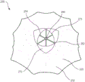
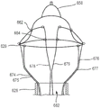
Fig. 3-5 are front, bottom, and top views of a prosthetic heart valve according to embodiments.
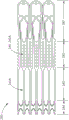
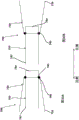
Fig. 6 is an open flattened view of the endoframe of the prosthetic heart valve of fig. 3-5 in an unexpanded configuration.
Fig. 7 and 8 are side and bottom views, respectively, of the inner frame of fig. 6 in an expanded configuration.
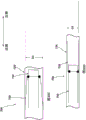
Fig. 9 is an open flattened view of the outer frame of the valve of fig. 3-5 in an unexpanded configuration.
Fig. 10 and 11 are side and top views, respectively, of the outer frame of fig. 9 in an expanded configuration.
Fig. 12 to 14 are a side view, a front view and a top view of an assembly of the inner frame of fig. 6 to 8 and the outer frame of fig. 9 to 11.
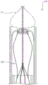
Fig. 15 is a side perspective view of an assembly of an inner frame and an outer frame shown in a biased expanded configuration, under an embodiment.
Fig. 16 is a side perspective view of the assembly of fig. 15, the outer frame shown inverted.
Fig. 17 is a side view of the assembly of fig. 16 shown in a collapsed configuration within the lumen of the delivery sheath.
Fig. 18 is a side view of the assembly of fig. 17 shown in a first partially deployed configuration.
Fig. 19 is a side view of the assembly of fig. 17 shown in a second partially deployed configuration.
Fig. 20 is a side view of the assembly of fig. 17, shown in a third partially deployed configuration with an inverted outer frame deployed substantially outside of the delivery sheath.
Fig. 21 is a side view of the assembly of fig. 17, shown in a fourth partially deployed configuration in which the outer frame has recovered and assumed a biased expanded configuration.
Fig. 22-24 illustrate steps of a portion of a method of delivering the prosthetic valve of fig. 15-21 into the atrium of the heart and into the native mitral annulus.
Fig. 25 is a schematic view of a delivery apparatus and a prosthetic heart valve according to an embodiment.
Fig. 26A is a side view of the prosthetic heart valve of fig. 25 shown within a delivery sheath and coupled to a portion of a valve holder.
Fig. 26B is a side view of an attachment member of the prosthetic valve of fig. 26A.
Fig. 26C is an end view of the valve holder of fig. 26A.
Fig. 27 is a cross-sectional side view of a prosthetic valve in a reverse configuration inside a delivery sheath, according to an embodiment.
Fig. 28 is a portion of a cross-sectional side view of a prosthetic valve in a reverse configuration inside a delivery sheath, including a dilator, according to an embodiment.
Fig. 29A is a cross-sectional side view of a prosthetic heart valve in a reverse configuration inside a lumen of a delivery sheath, according to an embodiment.
Fig. 29B is a side view of the prosthetic heart valve of fig. 9A in an inverted configuration and outside of the delivery sheath.
Fig. 30A and 30B are schematic views of a portion of a prosthetic heart valve according to an embodiment shown in first and second configurations, respectively.
Fig. 30C and 30D are schematic views of a portion of the prosthetic heart valve of fig. 30A and 30B, respectively, shown disposed within a delivery sheath.
Fig. 31A and 31B are schematic views of a portion of the prosthetic heart valve of fig. 30A and 30B shown in first and second configurations, respectively.
Fig. 32A is a schematic diagram of a side view of a delivery apparatus and a prosthetic heart valve, under an embodiment.
Fig. 32B is a schematic illustration of an end view of an elongate member of the delivery apparatus of fig. 32A.
Fig. 33A is a cross-sectional side view of a delivery sheath according to an embodiment, wherein the prosthetic valve is in an inverted configuration and disposed in the delivery sheath.
Fig. 33B is an illustration of a side view of the prosthetic heart valve of fig. 33A in an inverted configuration and outside of a delivery sheath.
Fig. 33C is an illustration of an end view of an elongate member of the delivery apparatus of fig. 33A.
Fig. 33D is an illustration of an end view of an elongate member of a delivery apparatus according to an embodiment.
Fig. 34 is a partial cross-sectional side view of a delivery system and a prosthetic heart valve according to an embodiment.
FIG. 35 is a cross-sectional view taken along line 35-35 in FIG. 34, showing an actuation wire coupled to a tube member of the delivery system.
Fig. 36 is a proximal end view of the tube member of the delivery system of fig. 34.
Fig. 37A is a side view of a portion of the tube member of fig. 36.
Fig. 37B is a side view of a portion of a multi-lumen tube member and a distal retaining element according to an embodiment, according to another embodiment.
Fig. 37C is a view of a portion of the multi-lumen tube member and distal retaining element of fig. 37B, according to another embodiment.
Fig. 38A-38D are each side views of different embodiments of an actuation wire.
Fig. 39 is a partial cross-sectional side view of the delivery system and prosthetic heart valve of fig. 34 shown in a first partially deployed configuration.
Fig. 40 is a partial cross-sectional side view of the delivery system and prosthetic heart valve of fig. 34 shown in a second partially deployed configuration.
Fig. 41 is a partial cross-sectional side view of the delivery system and prosthetic heart valve of fig. 34 shown in a third partially deployed configuration.
Fig. 42 is a cross-sectional view taken along line a-a of fig. 34, showing the actuation wire in a partially released position.
Fig. 43 illustrates a flow diagram of a method of delivering and deploying a prosthetic valve within a heart, according to an embodiment.
Fig. 44 illustrates a flow diagram of a method of delivering and deploying a prosthetic valve within a heart, according to an embodiment.
Detailed Description
Described herein are devices and methods for a prosthetic heart valve, such as a prosthetic mitral valve, that can be configured to move to an inverted configuration for delivery of the prosthetic valve into a patient's heart. As described herein, in some embodiments, the prosthetic valve includes an outer frame that can be inverted relative to an inner frame when the prosthetic valve is in a biased expanded configuration. The prosthetic mitral valve can be formed of, for example, a shape memory material. After reversing the outer frame, the prosthetic valve may be inserted into the lumen of the delivery sheath such that the prosthetic valve moves to the collapsed configuration.
The delivery sheath may be used to deliver a prosthetic heart valve (e.g., a prosthetic mitral valve) into a patient's heart using a number of different delivery routes for delivering the prosthetic heart valve, wherein an inverted prosthetic valve may enter the heart through an atrium of the heart. For example, the prosthetic valves described herein can be delivered using a trans-femoral delivery route as described in PCT international application nos. PCT/US15/14572 ("PCT application No. 572") and/or PCT international application nos. PCT/US16/12305 ("PCT application No. 305"), the disclosures of each of which are incorporated herein by reference in their entirety; or via the Transatrial route, such as described in U.S. provisional patent application serial No. 62/220,704 ("provisional application No. 704"), filed on 18.9.2015 for a Transatrial Delivery of Prosthetic Mitral Valve, "entitled" Apparatus and method for Transatrial Delivery, "the entirety of which is incorporated herein by reference. In another example, the Prosthetic valves described herein (e.g., a reverse Valve as described herein) may be delivered via a transjugular route, such as via the right atrium and through the atrial septum and into the left atrium, as described in U.S. provisional patent application serial No. 62/305,678 ("provisional application No. 678") entitled "Apparatus and Methods for Delivery of Prosthetic Mitral valves" and U.S. patent application publication No. 2017/0079790 ("publication No. 790"), entitled "Apparatus and Methods for delivering Prosthetic Mitral valves," each of which is incorporated herein by reference in its entirety. The prosthetic valves described herein can also be delivered apically, if desired. By the transapical approach, after the delivery sheath has been disposed within the left atrium of the heart, the prosthetic mitral valve is moved distally out of the delivery sheath such that the inverted outer frame is restored and the prosthetic valve assumes its biased expanded configuration. The prosthetic mitral valve can then be positioned within the mitral valve annulus of the heart.
In some embodiments, the device includes a delivery sheath defining a lumen, an elongate member defining first and second lumens and disposed at least partially within the lumen of the delivery sheath. The device also includes a prosthetic heart valve disposed at least partially within the lumen of the delivery sheath in the collapsed configuration and circumferentially surrounding a portion of the elongate member. The prosthetic heart valve includes an outer frame coupled to an inner frame. The outer frame is movable between a first configuration relative to the inner frame and a second configuration relative to the inner frame, wherein the outer frame is inverted relative to the inner frame. The prosthetic heart valve is disposed within the lumen of the delivery sheath, and the outer frame is in the second configuration and is disposed axially proximal of the inner frame. The device also includes a first actuation wire releasably coupled to the first portion of the outer frame and passing from the first portion through the first lumen of the elongate member and out the proximal end of the delivery sheath. The device also includes a second actuation wire releasably coupled to the second portion of the outer frame and passing from the second portion through the second lumen of the elongate member and out the proximal end of the delivery sheath. The first and second portions of the outer frame are configured to be disposed within an atrium of the heart when implanted within the heart.
In some embodiments, the method comprises: the distal end of the delivery sheath is inserted through the apical region of the heart and into the atrium of the heart. The delivery sheath has a prosthetic heart valve disposed within the lumen of the delivery sheath. The prosthetic heart valve includes an outer frame and an inner frame coupled to the outer frame. The outer frame is movable between a first position relative to the inner frame and a second position relative to the inner frame, wherein the outer frame is inverted relative to the inner frame. The prosthetic heart valve is disposed within the inner lumen of the delivery sheath, and the outer frame is in a second position relative to the inner frame during insertion of the distal end of the delivery sheath through the apical region of the heart and into the atrium of the heart. The method further comprises the following steps: the prosthetic heart valve is moved distally out of the delivery sheath. The method further comprises the following steps: transitioning an outer frame of the prosthetic heart valve to a first position relative to an inner frame such that the prosthetic heart valve at least partially assumes a biased expanded configuration. The method further comprises the following steps: the prosthetic heart valve is positioned within an annulus of the heart.
In some embodiments, the method comprises: the distal end of the delivery sheath is inserted into an atrium of the heart. The delivery sheath has a prosthetic heart valve disposed within the lumen of the delivery sheath. The prosthetic heart valve includes an outer frame and an inner frame coupled to the outer frame. The outer frame is movable between a first position relative to the inner frame and a second position relative to the inner frame, wherein the outer frame is inverted relative to the inner frame. The prosthetic heart valve is disposed within the inner lumen of the delivery sheath, the outer frame being in the second position relative to the inner frame during insertion of the distal end of the delivery sheath into the atrium of the heart, and being at least partially disposed axially proximal of the inner frame. The method further comprises the following steps: the prosthetic heart valve is moved distally out of the delivery sheath. The method further comprises the following steps: transitioning an outer frame of the prosthetic heart valve to a first position relative to an inner frame such that the prosthetic heart valve at least partially assumes a biased expanded configuration. The method further comprises the following steps: positioning a prosthetic heart valve within a body annulus of a heart.
In some embodiments, an apparatus includes an outer sheath defining a lumen, a delivery sheath defining a lumen and movably disposed within the lumen defined by the outer sheath, and a prosthetic heart valve disposed within the lumen of the delivery sheath in a collapsed configuration. The prosthetic heart valve includes an outer frame coupled to an inner frame. The inner frame is removably coupled to the distal end of the valve support. The outer frame is movable between a first configuration relative to the inner frame and a second configuration relative to the inner frame, wherein the outer frame is inverted relative to the inner frame. The prosthetic heart valve is disposed within the lumen of the delivery sheath with the outer frame in the second configuration. The device also includes a first actuation wire releasably coupled to the first portion of the outer frame and a second actuation wire releasably coupled to the second portion of the outer frame. Each of the first and second actuation wires has (1) a first portion extending proximally from the outer frame, through the lumen of the outer sheath, along the outer wall of the delivery sheath and through the first side aperture defined by the delivery sheath, and (2) a second portion extending proximally from the outer frame, through the lumen of the outer sheath, along the outside of all of the delivery sheath and through the second side aperture defined by the delivery sheath. The first and second portions of each of the first and second actuation wires are configured to be pulled proximally to push the outer frame from the second configuration toward the first configuration relative to the inner frame.
In some embodiments, the device comprises a prosthetic valve comprising an inner frame and an outer frame coupled to the inner frame at a plurality of coupling joints. The plurality of coupling joints are configured to allow the outer frame to move relative to the inner frame such that the prosthetic valve is movable between a first configuration and a second configuration. When the prosthetic valve is in the first configuration, the outer frame and the inner frame collectively define a first length of the prosthetic valve; when the prosthetic valve is in the second configuration, the outer frame and the inner frame collectively define a second length of the prosthetic valve, and the second length is greater than the first length. The inner frame has the same length when the prosthetic valve is in both the first configuration and the second configuration.
In some embodiments, the device comprises a prosthetic heart valve comprising an inner frame and an outer frame coupled to the inner frame at a plurality of coupling joints. The prosthetic valve is movable between a first configuration and a second configuration. The plurality of coupling joints are configured to allow the outer frame to move between a first position relative to the inner frame and a second position relative to the inner frame, wherein the outer frame is inverted relative to the inner frame. When the outer frame is in the first position, the prosthetic valve is in a first configuration; the prosthetic valve is in a second configuration when the outer frame is in the second position.
In some embodiments, the device comprises a prosthetic heart valve comprising an inner frame and an outer frame coupled to the inner frame at a plurality of coupling joints. The plurality of coupling joints are configured to allow the outer frame to move relative to the inner frame such that the prosthetic valve is movable between a first configuration and a second configuration. The outer frame has an outer frame coupling portion coupled to the inner frame at a plurality of coupling joints and an outer frame free end portion. The inner frame has an inner frame coupling part coupled to the outer frame at a plurality of coupling joints. The first end and the inner frame free end are on an end of the inner frame opposite the first end. The plurality of coupling joints are disposed between the outer frame free end and the inner frame first end when the prosthetic valve is in the first configuration. The plurality of coupling joints are disposed between the inner frame free end and the outer frame free end when the prosthetic valve is in the second configuration.
In some embodiments, the device comprises a prosthetic heart valve comprising an inner frame coupled to an outer frame at a plurality of coupling joints. The plurality of coupling joints are configured to allow the outer frame to move relative to the inner frame such that the prosthetic valve is movable between a first configuration and a second configuration. The outer frame has an outer frame coupling portion coupled to the inner frame at a plurality of coupling joints and an outer frame free end portion. The inner frame has an inner frame coupling portion coupled to the outer frame at a plurality of coupling joints and an inner frame free end. When the prosthetic valve is in the first configuration, the outer frame free end portion and the inner frame free end portion each open in the same direction. When the prosthetic valve is in the second configuration, the outer frame free end and the inner frame free end open in opposite directions.
In some embodiments, an apparatus includes a delivery sheath defining a lumen, a valve holder movably disposed within the lumen of the delivery sheath, and a prosthetic heart valve at least partially disposed within the lumen of the delivery sheath in a collapsed configuration. The prosthetic heart valve includes an outer frame coupled to an inner frame, and the inner frame is removably coupled to the distal end of the valve holder. The outer frame is movable between a first configuration relative to the inner frame and a second configuration relative to the inner frame, wherein the outer frame is inverted relative to the inner frame. The prosthetic heart valve is disposed within the lumen of the delivery sheath with the outer frame in the second configuration. The first actuation wire is releasably coupled to a first portion of the open free end of the outer frame and the second actuation wire is releasably coupled to a second portion of the open free end of the outer frame. Each of the first and second actuation wires has a first portion extending proximally from the outer frame and a second portion extending proximally from the outer frame. The first and second portions of each of the first and second actuation wires are configured to be pulled proximally to push the outer frame from the second configuration toward the first configuration relative to the inner frame.
In some embodiments, an apparatus includes an outer sheath defining a lumen, an inner sheath movably disposed within the lumen of the outer sheath and defining the lumen, a tube member movably disposed within the lumen of the outer sheath and defining the lumen, a valve holder movably disposed within the lumen of the inner sheath and within the lumen defined by the tube member, and a prosthetic heart valve disposed at least partially within the lumen of the outer sheath and at least partially within the lumen of the inner sheath. The prosthetic heart valve includes an outer frame coupled to an inner frame, and the inner frame is removably coupled to the distal end of the valve holder. The outer frame is movable between a first configuration relative to the inner frame and a second configuration relative to the inner frame, wherein the outer frame is inverted relative to the inner frame. The prosthetic heart valve is disposed within the inner lumen of the outer sheath and the inner sheath, and the outer frame is in the second configuration. The first actuation wire is releasably coupled to the first portion of the open free end of the outer frame and is releasably coupled to the tube member at a first location on the tube member. The second actuation wire is releasably coupled to the second portion of the open free end of the outer frame and is releasably coupled to the tube member at a second location on the tube member.
In some embodiments, the method comprises: the distal end of the delivery sheath is inserted into the left atrium of the heart. The delivery sheath has a prosthetic mitral valve disposed within an inner lumen of the delivery sheath, and the prosthetic mitral valve has an outer frame coupled to an inner frame such that the outer frame is movable between a first position relative to the inner frame and a second position relative to the inner frame, wherein the outer frame is inverted relative to the inner frame. The prosthetic valve is disposed within the lumen of the delivery sheath with the outer frame in a second position relative to the inner frame. The delivery sheath is moved distally out of the prosthetic mitral valve to return the outer frame of the prosthetic mitral valve to the first position relative to the inner frame such that the prosthetic mitral valve at least partially assumes the biased expanded configuration. The prosthetic mitral valve is positioned within a mitral valve annulus of the heart.
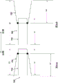
Fig. 1A and 1B are schematic views of a portion of a prosthetic heart valve 100 according to an embodiment shown in first and second configurations, respectively, while fig. 1C and 1D illustrate portions of the prosthetic heart valve 100 of fig. 1A and 1B shown disposed within a lumen of a delivery sheath 126, respectively. Fig. 2A and 2B illustrate a portion of the prosthetic heart valve 100 of fig. 1A and 1B, respectively, and show a length dimension of the prosthetic heart valve in each of a first configuration and a second configuration. As described above, in some cases, such as when delivering a prosthetic valve to the heart via a transfemoral, transatrial, or transjugular approach, the size of the prosthetic valve during delivery should be sized accordingly due to the small size of the lumen of the delivery sheath. Accordingly, it is desirable to have a prosthetic valve that can be reconfigured between a biased expanded configuration for implantation in the heart (e.g., within the native mitral valve annulus) and a delivery configuration having a smaller outer circumference or profile to allow delivery within the lumen of the delivery sheath. The prosthetic valve 100 and the embodiments of prosthetic valves described herein can be constructed and formed to achieve these desired functions and features.
The prosthetic heart valve 100 (also referred to herein as a "prosthetic valve" or "valve") may be, for example, a prosthetic mitral valve. Valve 100 includes an outer frame 120 and an inner frame 150. As described in more detail below with reference to fig. 3-15, the outer frame 120 and the inner frame 150 are each formed as a tubular structure. As described in more detail below, the outer frame 120 and the inner frame 150 may be coupled together at a plurality of coupling joints 146, the plurality of coupling joints 146 disposed about a perimeter of the inner frame 150 and a perimeter of the outer frame 120. Valve 100 may also include other features, such as those described below with respect to fig. 3-15. For illustrative purposes, the inner frame 150 and the outer frame 120 are discussed only with respect to fig. 1A-2B. The various features and characteristics of the valve 100 described with respect to fig. 1A-2B may be applicable to any of the prosthetic valves described herein.
The outer frame 120 is configured to have a biased expanded or undeformed shape and may be manipulated and/or deformed (e.g., compressed or constrained) and, when released, returns to its original (expanded or undeformed) shape. For example, the outer frame 120 may be formed of a material, such as metal or plastic, which has shape memory properties. Of metals, Nitinol (Nitinol)®) It has been found to be particularly useful because it can be processed to be austenitic, martensitic or superelastic. Other shape memory alloys, such as Cu-Zn-Al-Ni alloys and Cu-Al-Ni alloys, may also be used. The inner frame 150 may be made of Nitinol®Is formed by laser cutting a tube. The inner frame 150 may also have a biased expanded or undeformed shape, and may be manipulated and/or deformed (e.g., compressed and/or constrained), and when released, returns to its original (expanded or undeformed) shape. Further details regarding inner frame 150 and outer frame 120 are described below with respect to valve 200 and fig. 3-15.
The valve 100 can be delivered and deployed within the left atrium of the heart using a variety of different delivery routes, including, for example, the transfemoral delivery route as described in PCT application No. 572 and/or PCT application No. 305, incorporated by reference above, or the transatrial or transjugular delivery route as described in provisional application No. 704, provisional application No. 678, and publication No. 790, incorporated by reference above. As noted above, in some cases, such as when delivering a prosthetic valve to the heart via a transfemoral or transatrial approach, the size of the prosthetic valve during delivery should be sized accordingly due to the small size of the lumen of the delivery sheath. Accordingly, it is desirable to have a prosthetic valve that can be reconfigured between a biased expanded configuration for implantation in the heart (e.g., within the native mitral valve annulus) and a delivery configuration having a smaller outer circumference or profile to allow delivery within the lumen of the delivery sheath. The prosthetic valve 100 and the embodiments of prosthetic valves described herein can be constructed and formed to achieve these desired functions and features.
More specifically, the valve 100 can have a biased expanded configuration (as shown in fig. 1A and 2A), an inverted configuration (as shown in fig. 1B and 2B), and a compressed or collapsed configuration (as shown in fig. 1C and 1D). The expanded configuration allows valve 100 to function when implanted within the heart. The valve 100 can be moved to an inverted configuration and a compressed or collapsed configuration for delivery of the valve 100 to the patient's heart.
To enable the valve 100 to move to the inverted configuration, the outer frame 120 may be coupled to the inner frame 150 in a manner that allows the outer frame 120 to move relative to the inner frame 150. More specifically, the coupling joint 146 may couple the outer frame 120 to the inner frame 150 in a manner that allows the outer frame 120 to move relative to the inner frame 150. For example, in some embodiments, the coupling joint 146 may be configured to allow the outer frame 120 to rotate about the coupling joint 146 relative to the inner frame 150. In some embodiments, the coupling joint may provide a pivotal coupling between the outer frame 120 and the inner frame 150. In some embodiments, the coupling joint may provide a flexible attachment between the outer frame 120 and the inner frame 150. As described herein with reference to various embodiments of prosthetic valves, the coupling joint 146 can be of various different types and configurations. For example, the coupling joint 146 may include a living hinge, a flexible member, a suture wound through an opening, a pin or tab inserted through an opening, or any combination thereof.
To move the valve 100 from the expanded configuration (fig. 1A) to the inverted configuration (fig. 1B), the outer frame 120 is moved to the prolapsed or inverted configuration relative to the inner frame 150 by moving (e.g., rotating, pivoting, flexing) the outer frame 120 about the coupling joint 146, as shown in fig. 1B, 1D, and 2B. The elastic or superelastic structure of the outer frame 120 of the valve 100 also allows the outer frame 120 to be moved to and disposed in a prolapsed or inverted configuration relative to the inner frame 150. To move the outer frame 120 into an inverted configuration relative to the inner frame 150, the outer frame 120 is folded or inverted distally (to the right in fig. 1B) relative to the inner frame 150 via the coupling joint 146. As shown in fig. 1A and 2A, the outer frame 120 is in a first position relative to the inner frame 150 prior to inversion, with the open or free end 116 (also referred to as the atrial portion 116 of the outer frame 120) disposed proximal or left of the coupling joint 146 and in the same direction as the free end 147 (also referred to as the second end of the inner frame) of the inner frame 150. When the outer frame 120 is moved to the inverted configuration (i.e., the second position relative to the inner frame 150), the free end 116 is disposed distal (or to the right in fig. 1B and 2B) of the coupling joint 146 and in a direction opposite the free end 147 of the inner frame 150. In other words, when the valve 100 is in the biased expanded configuration (e.g., fig. 1A), the coupling joint 146 is disposed between the first end 144 (also referred to as a tether coupling) of the inner frame 150 and the free end 116 of the outer frame 120. When the valve 100 is in the inverted configuration (e.g., fig. 1B) (i.e., the outer frame 120 has been moved to the inverted configuration or position), the coupling joint 146 is disposed between the free end or second end 147 of the inner frame 150 and the free end 116 of the outer frame 120.
When in the inverted configuration, the overall length of valve 100 is increased, but the length of inner frame 150 and the length of outer frame 120 remain the same (or substantially the same). For example, as shown in fig. 2A and 2B, the overall length L1 of the valve 100 in the biased expanded configuration (prior to reversal as shown in fig. 2A) is less than the overall length L2 of the valve 100 when in the reversed configuration (fig. 2B). When valve 100 is in both the biased expanded configuration and the inverted configuration, length Li of inner frame 150 and length Lo of outer frame 120 are substantially the same (or the same). Additionally, in some examples, depending on the particular configuration of the outer frame, the overall outer circumference or outer diameter of the valve 100 can be smaller when the valve 100 is in the inverted configuration.
With valve 100 in the inverted configuration, valve 100 can be placed within the lumen of delivery sheath 126 for delivery of valve 100 to the left atrium of the heart, as shown in fig. 1D. When placed within the lumen of the delivery sheath 126, the valve 100 moves to a collapsed or compressed configuration in which the outer diameter or outer circumference of the valve 100 is reduced. Because valve 100 is in the inverted configuration, valve 100 can be placed within a smaller delivery sheath 126 than would otherwise be possible. For example, for comparison purposes, fig. 1C illustrates the valve 100 placed within the lumen of the delivery sheath 126', wherein the valve 100 has not been moved to the inverted configuration prior to being disposed within the delivery sheath 126'. As shown in fig. 1C, when in the inverted configuration, the outer diameter of the valve 100 is reduced, but not as small as the diameter of the valve 100 when placed in the delivery sheath 126. Thus, in fig. 1C, the overall outer circumference or outer diameter of the valve 100 is D1, and in fig. 1D, the overall outer circumference or outer diameter of the valve 100 is D2, which is less than D1.
Thus, by placing the outer frame 120 in the inverted configuration, the valve 100 can be collapsed to a smaller overall diameter, i.e., placed in a smaller diameter delivery sheath 126 if the valve 100 were only radially collapsed. This is because when the valve is in the biased expanded configuration, the inner frame 150 nests within the interior of the outer frame 120, and therefore the outer frame 120 must contract around the inner frame 150. In some embodiments, the inner frame 150 and the outer frame are concentrically arranged. While in the inverted configuration, the inner frame 150 and the outer frame 120 are axially arranged relative to each other (i.e., the inner frame is not nested within the outer frame 150) such that the outer frame 120 may be collapsed without accommodating all of the structure of the inner frame 150 within. In other words, where the inner frame 150 is disposed mostly inside the outer frame 120 or nested within the outer frame 120, the layers or pieces of the frame structure cannot be compressed to such a small diameter. In addition, if the frames are nested, the structure is less flexible, thus requiring more force to bend the valve, for example to traverse tortuous vasculature or make tight turns in the left atrium after traversing the atrial septum, to properly orient for insertion into the mitral annulus.
Fig. 3-14 illustrate another embodiment of a prosthetic heart valve that can be delivered and deployed within the left atrium of the heart using a variety of different delivery routes, including, for example, a transfemoral delivery route or a transatrial delivery route. Fig. 3-5 are front, bottom, and top views, respectively, of a prosthetic heart valve 200 according to an embodiment. The prosthetic heart valve 200 (also referred to herein as a "valve" or "prosthetic valve") is designed to replace a damaged or diseased native heart valve, such as a mitral valve. The valve 200 includes an outer frame assembly 210 and an inner valve assembly 240 coupled to the outer frame assembly 210.
As shown, the outer frame assembly 210 includes an outer frame 220 covered on all or a portion of its outer surface with an outer covering 230 and covered on all or a portion of its inner surface with an inner covering 232. The outer frame 220 may provide several functions for the prosthetic heart valve 200, including serving as a primary structure, as an anchoring mechanism to anchor the valve to the native heart valve device and/or attachment points for a separate anchoring mechanism, carrying supports for the inner valve assembly 240 and/or a seal to inhibit paravalvular leakage between the prosthetic heart valve 200 and the native heart valve device.
The outer frame 220 has a biased expanded configuration and may be manipulated and/or deformed (e.g., compressed and/or constrained) and, when released, returns to its original unconstrained shape. To accomplish this, the outer frame 220 may be formed of a material, such as metal or plastic, that has shape memory properties. With respect to metals, Nitinol®It has been found to be particularly useful because it can be processed to be austenitic, martensitic or superelastic. Other shape memory alloys, such as Cu-Zn-Al-Ni alloys and Cu-Al-Ni alloys, may also be used.
As best shown in fig. 3, the outer frame assembly 210 has an upper end (e.g., at the atrial portion 216), a lower end (e.g., at the ventricular portion 212), and an intermediate portion therebetween (e.g., at the annulus portion 214). An upper end or atrial portion 216 (also referred to as an "outer free end") defines an open end of the outer frame assembly 210. The middle or annulus portion 214 of the outer frame assembly 210 has a perimeter that is configured (e.g., sized, shaped) to fit into the annulus of a native atrioventricular valve. The circumference of the upper end of the outer frame member 210 is greater than the circumference of the middle portion. In some embodiments, the perimeter of the upper end of the outer frame assembly 210 is substantially greater than the perimeter of the middle portion. As best shown in fig. 5, the upper end and the middle portion of the outer frame member 210 have a D-shaped cross-section. In this way, the outer frame assembly 210 promotes proper fit into the annulus of the native atrioventricular valve.
The inner valve assembly 240 includes an inner frame 250, an outer covering (not shown), and leaflets (leaflets) 270. As shown, the inner valve assembly 240 includes an upper portion having a perimeter formed with a plurality of arches. The inner frame 250 comprises six axial posts or frame members that support the outer cover and leaflets 270 of the inner valve assembly 240. The leaflets 270 are attached along three of the posts, shown as commissure posts 252 (best shown in fig. 4), and the outer cover of the inner valve assembly 240 is attached to the other three posts 254 (best shown in fig. 4), and optionally to the commissure posts 252. The inner valve assembly 240 and each outer covering of the leaflets 270 are formed from approximately rectangular pieces of material that are joined together at their upper or atrial ends. The lower ventricular end of the outer cover of the inner valve assembly 240 may be bonded to the inner cover 232 of the outer frame assembly 210, and the lower ventricular end of the leaflet 270 may form a free edge 275, albeit coupled to the lower end of the commissure posts 252.
Although the inner valve assembly 240 is shown as having three leaflets, in other embodiments, the inner valve assembly can include any suitable number of leaflets. The leaflets 270 are movable between an open configuration and a closed configuration, wherein the leaflets 270 are engaged (flap) or in contact in the sealing abutment faces.
The outer cover 230 of the outer frame assembly 210 and the inner cover 232 of the outer frame assembly 210, the outer cover 260 of the inner valve assembly 240, and the leaflets 270 of the inner valve assembly 240 can be formed of any suitable material or combination of materials such as those discussed above. In this embodiment, the inner cover 232 of the outer frame assembly 210, the outer cover of the inner valve assembly 240, and the leaflets 270 of the inner valve assembly 240 are at least partially formed of porcine pericardium. Also, in this embodiment, the outer cover 230 of the outer frame assembly 210 is at least partially formed of polyester.
The inner frame 250 is shown in more detail in fig. 6-8. In particular, fig. 6-8 show the inner frame 250 in an undeformed, initial state (fig. 6), a side view of the inner frame 250 in an expanded configuration (fig. 7), and a bottom view of the inner frame 250 in the expanded configuration (fig. 8), respectively, according to embodiments.
In this embodiment, the inner frame 250 is made of Nitinol®Is formed by laser cutting a tube. The inner frame 250 is illustrated in an undeformed, initial state, i.e., cut as a laser but cut and deployed into a flat sheet for ease of illustration, in fig. 6. The inner frame 250 may be divided into four parts, corresponding to functionally different parts of the final form of the inner frame 250: an atrial portion 247, a body portion 242, a strut portion 243, and a tether clip or connecting portion 244. The strut portion 243 includes six struts, such as strut 243A, that connect the body portion 242 to the tether connection portion 244.
The tether connecting portion 244 (also referred to as the first end of the inner frame) comprises a longitudinally extending portion of the strut that is circumferentially connected by a pair of opposed somewhat V-shaped connecting members (or "micro-V"). The tether connecting portion 244 is configured to radially contract by applying a compressive force that causes the micro-V to become deeper V-shaped with the apex moving longitudinally closer and the open end of the V moving circumferentially closer. Thus, the tether coupling portion 244 may be configured to compressively grip or grip one end of the tether, either directly to the tether line (e.g., a braided filament line) or to an intermediate structure such as a polymer or metal sheet that is permanently secured to the tether line.
In contrast to the tether connecting portion 244, the atrial portion 247 (also referred to as "inner frame free end") and the body portion 242 are configured to radially expand. The strut portion 243 forms a longitudinal connection and a radial transition between the expanded body portion and the compressed tether coupling portion 244. The body portion 242 provides an inner frame coupling part 245, the inner frame coupling part 245 comprising six longitudinal posts, such as post 242A. The inner frame coupling portion 245 may be used to attach the leaflets 270 to the inner frame 240 and/or may be used to attach the inner assembly 240 to the outer assembly 210, such as by connecting the inner frame 250 to the outer frame 220. In the illustrated embodiment, the post includes an opening through which a connecting member (such as a suture filament and/or wire) may pass to couple the post to other structures.
Fig. 7 and 8 show the inner frame 250 in a fully deformed (i.e., final deployed) configuration in side and bottom views, respectively.
Fig. 9-11 illustrate the outer frame 220 of the valve 200 in more detail. In this embodiment, the outer frame 220 is also made of Nitinol®Is formed by laser cutting a tube. Fig. 9 illustrates the outer frame 220 in an undeformed initial state (i.e., as laser cut, but cut and unfolded into a flat sheet for ease of illustration). The outer frame 220 may be divided into an outer frame coupling portion 271, a body portion 272, and a cuff portion 273 (which includes the atrium or free end portion 216), as shown in fig. 9. The outer frame coupling portion 271 includes a plurality of openings or eyelets, such as 271A, through which the outer frame 220 may be coupled to the inner frame 250, as discussed in more detail below.
Fig. 10 and 11 show the outer frame 220 in a fully deformed (i.e., final deployed) configuration in side and top views, respectively. As best shown in fig. 11, the lower end of the outer frame coupling portion 271 forms a substantially circular opening (denoted by "O" in fig. 11). The diameter of the opening preferably substantially corresponds to the diameter of the body portion 242 of the inner frame 250 to facilitate coupling of the two components of the valve 200.
Fig. 12-14 show the outer frame 220 and the inner frame 250 coupled together in front, side and top views, respectively. The two frames together form a structural support for a prosthetic valve, such as valve 200. The frame supports the valve leaflet structure (e.g., leaflets 270) in a desired relationship with the native valve annulus, supports the covers for both frames (e.g., outer cover 230, inner cover 232, outer cover of inner valve assembly 240) to provide a barrier to blood leakage between the atrium and ventricle, and is coupled (via inner frame 250) to a tether (e.g., tether assembly 290) to help hold prosthetic valve 200 in place in the native valve annulus by its tether connection to the ventricular wall. The outer frame 220 and the inner frame 250 are connected at six coupling points (representative points are identified as "C"). In this embodiment, the coupling points are achieved with mechanical fasteners (such as short lengths of wire) that pass through eyelets (such as the eyelet 271A) in the outer frame coupling portion 271 and corresponding openings (e.g., longitudinal posts, such as the post 242A) in the inner frame coupling portion 245 in the body portion 242 of the inner frame 250. Accordingly, the inner frame 250 is disposed within the outer frame 220 and is securely coupled to the outer frame 220.
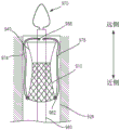
Fig. 15-21 illustrate a method of reconfiguring a prosthetic heart valve 300 (e.g., a prosthetic mitral valve) prior to inserting the prosthetic heart valve 300 into a delivery sheath 326 (see, e.g., fig. 17-21) for delivery into an atrium of a heart. The prosthetic heart valve 300 (also referred to herein as a "valve") can be configured the same as or similar to the valves 100 and 200 described above, and function the same or similar. Accordingly, some details regarding the valve 300 are not described below. It should be understood that for features and functions not specifically discussed, those features and functions may be the same as or similar to valve 200.
As shown in fig. 15, the valve 300 has an outer frame 320 and an inner frame 350. As discussed above with respect to valves 100 and 200, outer frame 320 and inner frame 350 of valve 300 can each be formed of a shape memory material and have a biased expanded configuration. The outer frame 320 and inner frame 350 may be moved to a collapsed configuration for delivery of the valve 300 to the heart. In an exemplary method of preparing the valve 300 for delivery to the heart, the outer frame 320 of the valve 300 is first positioned in a prolapsed or inverted configuration as shown in fig. 16. In particular, the elastic or superelastic structure of the outer frame 320 of the valve 300 allows the outer frame 320 to be disposed in a prolapsed or inverted configuration prior to insertion of the valve 300 into the lumen of the delivery sheath 326. As shown in fig. 16, to dispose the outer frame 320 in the inverted configuration, the outer frame 320 is folded or inverted distally (to the right in fig. 16) such that the open free end 316 of the outer frame 320 faces away from the open free end 347 of the inner frame 350. As described above for valve 100, in this inverted configuration, the entire outer circumference or outer diameter of valve 300 is reduced and the entire length is increased. For example, the diameter D1 shown in fig. 15 is greater than the diameter D2 shown in fig. 16, and the length L1 (of the valve 200 shown in fig. 12) is less than the length L2 of the valve 300 shown in fig. 16. With the outer frame 320 in an inverted configuration relative to the inner frame 350, the valve 300 can be placed within the lumen of the delivery sheath 326, as shown in fig. 17, for delivery of the valve 300 to the left atrium of the heart. By disposing the outer frame 320 in an inverted configuration relative to the inner frame 350, the valve 300 can be collapsed to a smaller overall diameter, i.e., when placed in a delivery sheath that is radially collapsed without an inverted diameter, than the valve 300 in the configuration shown in fig. 15. This is because in the configuration shown in fig. 15, the two frames are concentric or nested, and therefore the outer frame 320 must be collapsed around the inner frame 350, whereas in the configuration shown in fig. 16, the two frames are substantially coaxial but not concentric or nested. Thus, in the configuration shown in fig. 16, the outer frame 320 can be collapsed without accommodating the inner frame 350 inside thereof. In other words, where the inner frame 350 is disposed mostly inside the outer frame 320 or nested within the outer frame 320, the layers or pieces of the frame structure cannot be compressed to such a small diameter. In addition, if the frames are nested, the structure is less flexible, thus requiring more force to bend the valve, for example to traverse tortuous vasculature or make tight turns in the left atrium after traversing the atrial septum, to properly orient for insertion into the mitral annulus.
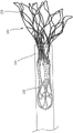
Fig. 22-24 illustrate a portion of a procedure for delivering a valve 300 to the heart. In this embodiment, the valve 300 is shown being delivered via a transfemoral delivery pathway such as described in PCT application No. 572 and/or PCT application No. 305, which are incorporated by reference above. With the valve 300 disposed within the lumen of the delivery sheath 326 and in the inverted configuration as shown in fig. 17, the delivery sheath 326 may be inserted into a femoral puncture, through the femoral vein, through the inferior vena cava, into the right atrium, through the septum Sp, and into the left atrium LA of the heart. With the distal end of the delivery sheath 326 disposed within the left atrium of the heart, the valve 300 can be deployed outside of the distal end of the delivery sheath 326. For example, in some embodiments, the pusher device 338 can be used to move or push the valve 300 out of the distal end of the delivery sheath 326. As shown in fig. 22-24, a tether 336 may be attached to the valve 300 and extend through the mitral valve annulus, through the left ventricle LV, and out of the puncture site at the apex Ap. In some embodiments, the valve 300 can be removed from the delivery sheath 326 by pulling proximally on the tether 336. In some embodiments, the valve 300 can be deployed by pushing with a pusher device and pulling with a tether.
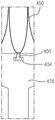
As the valve 300 exits the lumen of the delivery sheath 326, the outer frame assembly 310 first exits in its inverted configuration as shown in the progression of fig. 18-20 (see also fig. 22). After the outer frame assembly 310 is completely outside of the lumen of the delivery sheath 326, the outer frame 320 may return to its expanded or deployed configuration as shown in fig. 21, 23, and 24. In some embodiments, due to its shape memory properties, the outer frame 320 may automatically recover after completely exiting the lumen of the delivery sheath. In some embodiments, a delivery sheath or a component of another device may be used to assist in the retrieval of the outer frame assembly 310. In some embodiments, a pusher device and/or tether may be used to help restore the outer frame assembly 310. The valve 300 may continue to deploy until the inner frame 350 is fully deployed with the left atrium and the valve 300 is in the expanded or deployed configuration (e.g., as shown in fig. 15 and 24). The valve 300 and tether 336 can then be secured to the apex of the heart using an epicardial pad device 339, as shown in fig. 24 and described in greater detail in PCT application nos. 572 and 305.
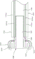
Fig. 25 schematically illustrates another embodiment of a delivery system that may be used to deliver and deploy a prosthetic heart valve within a patient's heart, for example, via a transvascular approach. In this embodiment, the delivery system 405 includes a delivery sheath 426, a valve support 438 (also referred to as a "pusher"), and one or more actuation wires 474 and 476. In this schematic, only two actuation wires are illustrated, but in other embodiments only one actuation wire or more than two actuation wires may be used.
The delivery sheath 426 can be used to deliver the valve 400, the valve 400 including an inner valve assembly 440 and an outer frame assembly 410, the valve assembly 440 including an inner frame (not labeled in fig. 25), and the outer frame assembly 410 including an outer frame (not labeled in fig. 25). The valve 400 can be configured to be the same as or similar to any prosthetic valve described herein and/or described in PCT application No. 305, and function the same as or similar, and can be moved between a deployed or expanded configuration and a delivery configuration, wherein the outer frame is disposed in a reversed position relative to the inner frame, as described herein and/or in PCT application No. 305. As shown in fig. 25, the valve 400 can be disposed within the lumen of the delivery sheath 426 when the valve is in the delivery configuration (i.e., the outer frame is inverted relative to the inner frame). In this embodiment, the outer frame member 410 is disposed distal to the inner valve member 440 when in a delivery configuration and placed within a delivery sheath. The valve holder 438 is coupled to the inner valve assembly 440 and the actuation wires are coupled to the outer valve assembly 410. The valve support 438 can be releasably coupled to the inner valve assembly 440 via a coupler 406, the coupler 406 being attached to the inner valve assembly 440, as shown in fig. 26A-26C. In this embodiment, the coupler 406 is in the shape of a T-bar or hammer. It should be understood that couplers having other configurations and shapes may be used.
As shown in fig. 26A, the coupler 406 is received within the recess 404, and the valve 400 and the valve holder 438 can be disposed within the lumen of the delivery sheath 426. The inner diameter of the delivery sheath 426 is sized such that the coupler 406 cannot exit the recess 404 when the valve holder 438 and the valve 400 are disposed therein. In other words, the inner wall of the delivery sheath 426 maintains the coupler 406 within the recess 404. When the valve 400 is moved outside of the delivery sheath 426, the coupler 406 will be able to freely exit the recess 404, releasing the inner frame 450 from the valve holder 438.
In alternative embodiments, the valve holder 438 may be removably coupled to the valve 400 (e.g., the endoframe 450 of the valve 400) via wires or sutures, which may be cut after delivery of the valve 400 to the heart. In some cases, the valve holder 438 can be decoupled from the valve 400 while the valve is still disposed within the delivery sheath 426, while in other instances the valve holder 438 can be decoupled from the valve 400 after the valve 400 exits the delivery sheath 426 within the heart.
The actuation wires 474 and 476 may be coupled to the outer frame of the outer frame assembly 410 using a variety of different coupling methods. For example, the outer frame 410 may include a loop (as described in PCT application No. for the outer frame 510, the outer frames 1010, and 305 herein) through which the actuation wires 474 and 476 may be received or wound. The number of rings on the outer frame may vary, and the number of rings through which each actuation wire is connected may vary. For example, in some embodiments, the outer frame includes 12 rings, and the first actuation wire is threaded through 6 of the rings, and the second actuation wire is threaded through 6 of the rings. In other embodiments, the outer frame may include 12 rings, and there may be 4 actuation wires, each actuation wire coupled to 3 of the rings. In some embodiments, a single actuation wire is coupled through all of the rings of the outer frame.
In this embodiment, the delivery sheath 426 can be used to deliver the valve 400 to the left atrium of the heart using a transvascular approach (e.g., transfemoral, transatrial). When the distal end of the delivery sheath 426 is disposed within the left atrium, the valve 400 is moved out of the lumen of the delivery sheath 426 using the actuation wires 474, 476 to help pull the valve 400 out of the delivery sheath 426. In some cases, the valve holder 438 can also be used to push the valve 400 out of the delivery sheath 426. More specifically, the actuation wires 474 and 476 may extend from the outer frame assembly 410 out the distal end of the delivery sheath and toward the proximal end. In some embodiments, the actuation wires 474, 476 extend proximally outside the delivery sheath 426 and then return through side eyelets or holes (not shown) into the lumen of the delivery sheath 426 and then exit the proximal end of the delivery sheath 426. Thus, a user (e.g., a physician) may pull the proximal ends of the actuation wires 474 and 476 to, in turn, pull the outer frame assembly 410 out of the distal end of the delivery sheath 426. In some embodiments, the actuation wires 474, 476 extend proximally from the outer frame assembly 410, back through the distal end of the delivery sheath 426 (e.g., rather than through a side aperture or hole of the delivery sheath) and into the lumen of the delivery sheath, and then out the proximal end of the delivery sheath 426. Various embodiments and configurations are described in more detail below.
When the outer frame assembly 410 exits the delivery sheath 426, it will still be in an inverted configuration relative to the inner valve assembly 440. While the outer frame assembly 410 is at least partially outside the lumen of the delivery sheath 426, the outer frame assembly 410 may begin to return to its expanded or deployed configuration (not shown in fig. 25). However, in this embodiment, the actuation wires 474 and 476 may be used to selectively (e.g., by an operator) assist and/or control the expansion, deployment, and/or articulation of the valve 400 as the valve 400 is delivered to the heart. In this manner, in use, the proximal ends of the actuation wires 474, 476 may be pulled distally to manipulate the outer frame assembly 410 to assist and control the transition of the outer frame assembly 410 from its inverted configuration relative to the inner valve assembly 440 to its expanded or deployed configuration (not shown). In some embodiments, the actuation wires 474, 476 may be manually grasped by a user to pull the actuation wires proximally. In some embodiments, the actuation wires 474, 476 may be operably coupled to the delivery system 405 such that a user does not have to manually handle the actuation wires. For example, the actuation wire may be coupled to a delivery sheath and/or a handle assembly (not shown) of the delivery system 405. Various embodiments of the delivery system are described in more detail below and in PCT application No. 305.
Fig. 27 illustrates an embodiment of a delivery system 505, the delivery system 505 may be used to deliver and deploy a prosthetic heart valve 500 (also referred to herein as a "valve") within the heart in a procedure similar to or identical to that described with respect to other embodiments described herein (e.g., the embodiments shown and described in fig. 34-42) and PCT application No. 305. Accordingly, some details regarding the valve 500 and the procedures performed therewith are not described herein. It should be understood that for features and functions not specifically discussed, those features and functions may be the same as or similar to the valves described herein (e.g., valve 1000) and/or the valve described in PCT application No. 305. The valve 500 can be configured to be the same as or similar to any of the valves described herein and/or in PCT application No. 305, and to function the same or similar. For example, the valve 500 includes an outer frame assembly having an outer frame 520, an inner valve assembly 540, and a tether 536, the inner valve assembly 540 having an inner frame 550, the tether 536 being coupled to the inner valve assembly. The delivery system 505 includes an outer delivery sheath 526, an inner sheath 508, a valve support 538 (also referred to as a "pusher"), and a multi-lumen elongate tube member 503 (also referred to as a "tube" or "tube member" or "multi-lumen elongate member"). As shown in fig. 27, the inner sheath 508 is movably disposed within the lumen 582 defined by the outer delivery sheath 526, and the tube member 503 is movably disposed within the lumen 583 defined by the inner sheath 508. The valve support 538 is movably disposed within a lumen 583 defined by the inner sheath 508.
As with the other embodiments described herein and the embodiment of PCT application No. 305, the valve 500 can be moved from the biased expanded configuration to an inverted configuration for delivery of the valve 500 to the heart. More specifically, to place the valve 500 in the inverted configuration, the outer frame 520 can be moved to the inverted configuration relative to the inner frame 550. In this embodiment, when the valve 500 is in the inverted configuration, the valve 500 is at least partially disposed within the lumen of the inner sheath 508 and is disposed near the distal end of the inner sheath 508. The valve support 538 is also disposed within the lumen 583 of the inner sheath 508. The inner frame 550 can be releasably coupled to the valve support 538 with a coupler 506 in the same or similar manner as any of the couplers described above with respect to coupler 406, coupler 1006, and/or PCT application No. 305. Similarly, the outer frame 520 includes a ring 562 through which actuation wires 574-577 can be threaded in the same or similar manner as described herein (e.g., with respect to the valve 1000) and/or in PCT application No. 305. The inner sheath 508 is movably disposed within the outer delivery sheath 526. As shown in fig. 6, a portion of the valve 500 is disposed outside of the inner sheath 508 and within the lumen 582 of the outer delivery sheath 526. In some cases, the entire valve 500 can be disposed within the lumen 583 of the inner sheath 508 prior to performing the procedure to deploy the valve.
In this embodiment, the inner sheath 508 defines a side aperture 509, and the actuation wire 574 and 577 may pass through the side aperture 509. More specifically, as shown in FIG. 27, when the valve 500 is disposed within the lumen 583 of the inner sheath 508, the actuation wires 574 and 577 extend proximally from the outer frame 520, along the outside of the inner sheath 508 and within the lumen 582 of the outer delivery sheath 526, back through the side aperture 509 defined by the inner sheath 508, within the lumen 583 of the inner sheath 508 and pinned to the tube member 503 by elongated pinning members 578-1, 578-2, 578-3, 578-4 (collectively referred to as pinning members 578; the pinning members 578-3 and 578-4 are not shown in FIG. 27; for purposes of illustration refer to the pinning members 1078-3 and 1078-4 shown and described with respect to FIGS. 35-37A). As shown, the first end of actuation wire 574 and the first end of actuation wire 575 are pinned by pinning member 578-2, and the first end of actuation wire 576 and the first end of actuation wire 577 are pinned by pinning member 578-1. The second ends of actuation wires 574 and 576 are pinned by pinning members 578-4 (not shown) and the second ends of actuation wires 575 and 577 are pinned by pinning members 578-3 (not shown).
The actuation wires 574 and 577 may be pinned to the tube member 503 by pinning members 578-1, 578-2, 578-3, 578-4 in the same or similar manner as described below with respect to the delivery system 1005. Accordingly, some details regarding, for example, the tube member 503, the pinning members 578-1, 578-2, 578-3, 578-4, and the actuation wire 574 and 577, as well as procedures performed therewith, are not described with respect to this embodiment. It should be understood that for features and functions not specifically discussed with respect to this embodiment, those features and functions may be the same as or similar to the transport system described herein (e.g., transport system 1005) and/or the transport system described in PCT application No. 305.
A user (e.g., a physician) can control and/or manipulate the movement and/or deployment of the valve 500, such as described for the delivery system 1005, using the tube member 503 to which the actuation wires 574 and 577 are coupled. In this embodiment, as illustrated, at least a portion of the actuation wire 574 and 577 can be disposed within the interior of the delivery sheath 526, thereby limiting the area of the actuation wire 574 and 577 exposed outside of the delivery sheath 526 for delivery and/or deployment of at least a portion of the valve 500. Although the side eyelet 509 defined by the inner sheath 508 is shown as being disposed at or near the distal end of the inner sheath 508, in other embodiments, the side eyelet 509 may be disposed at any suitable location along the length of the inner sheath 508 (e.g., toward an intermediate or proximal portion of the management sheath).
In this embodiment, to deliver the valve 500 to the heart, the distal end of the outer delivery sheath 526, in which the valve 500, the inner sheath 508, the valve seat 538, and the tube member 503 are disposed, is disposed within the left atrium of the heart. With the distal end of the delivery sheath 526 disposed within the left atrium of the heart, the valve 500 can be deployed outside of the delivery sheath 526. For example, the inner sheath 508, the valve support 538, and the tube member 503 may be moved distally relative to the outer sheath 526 to move or push the valve 500 out of the lumen 582 of the outer sheath 526. Additionally or alternatively, the outer sheath 526 can be moved or pulled proximally, leaving at least a portion of the valve 500 disposed within the heart. In some examples, a tether 536 coupled to the valve 500 can be used to help pull the valve 500 out of the lumen 582 of the outer sheath 526.
As described in other embodiments herein and in embodiments of PCT application No. 305, when the outer frame 520 is unconstrained by the outer sheath 526, the outer frame 520 may begin to return to its expanded or non-inverted configuration. Actuation wires 575-. More specifically, after outer frame 520 is at least partially disposed outside the distal end of outer sheath 526, tube member 503 may be pulled proximally such that the actuation wire (pinned to tube member 503) pulls the distally disposed portion of outer frame 520 proximally (same or similar to that shown in fig. 40) in a controlled manner and such that the outer frame 520 may be controlled to recover from its inverted configuration relative to inner frame 550.
Additionally, in some instances, the actuation wires 574 and 577 may help articulate and place the valve 500 into its destination (e.g., the native annulus of an atrioventricular valve of the heart). For example, the actuation wires 574 and 577 can also be used to constrain, contract, or otherwise move the valve 500 (e.g., radially compress the outer frame 520 of the valve 500) after the valve 500 exits the outer sheath 526 and is in its restored expanded or partially expanded configuration. More specifically, in this embodiment, the tube member 503 with the actuation wire 574 and 577 pinned thereto may be manipulated by a user to move or push the outer frame 520 to a more compressed configuration (similar or identical to that shown in FIG. 41) by pulling or moving the tube member 503 proximally. For example, it may be desirable to reposition the valve 500 within the heart prior to fully deploying the valve 500.
With the outer frame 520 of the valve 500 disposed in its non-inverted and at least partially expanded configuration and in a desired position within the heart, the inner frame 550 can be deployed. As described in PCT application No. 305 for the valve 2100, to decouple the inner frame 550 from the valve support 538, the valve support 538 can be moved distally and/or the inner sheath 508 can be moved proximally such that the valve support 538 is disposed outside the lumen 583 of the inner sheath 508. As such, the coupler 506 may be released from the recess 504, releasing or decoupling the inner frame 550 from the valve support 538. In some embodiments, the tether 536 may be pulled to assist in moving the inner frame 550 out of the inner sheath 508. When the inner frame 550 is released from the valve support 538 and disposed outside the inner sheath 508, the inner frame 550 may assume its biased expanded configuration.
The actuation wires 574 and 577 may also be released from or decoupled from the outer frame 520 before or after the inner frame 550 is released from the valve support 538. To decouple the actuation wires 574 and 577 from the outer frame 520, one end of each of the actuation wires 574 and 577 may be pulled or decoupled from the tube member 503. For example, the pinning member 578-3 can be withdrawn proximally from the groove of the tube member 503 (the same or similar to the groove as shown in and described with respect to the delivery system 1005) such that the second end of the actuation wire 577 and the second end of the actuation wire 575 are each released or pulled from the tube member 503, but remain pinned by the pinning members 578-2 and 578-1, respectively. Similarly, the pinning member 578-4 can be withdrawn proximally from the recess such that the second end of the actuation wire 574 and the second end of the actuation wire 576 can each be released or pulled away from the tube member 503, but remain pinned by the pinning members 578-2 and 578-1, respectively. With one end of each of actuation wires 575 & 577 coupled to tube member 503 (via pinning members 578-1 and 578-2 in this example), tube member 503 may be pulled proximally, which in turn pulls the opposite end of actuation wires 574 & 577 out of loop 562 of outer frame 520. Thus, with the actuation wires 574 and 577 separated from the outer frame 520, the outer frame may assume a biased expanded or partially expanded configuration.
Although in the above example, it was described that the pinning members 578-3 and 578-4 were withdrawn to release the ends of the actuation wires 574-577, alternatively, the pinning members 578-1 and 578-2 may be withdrawn, leaving the actuation wires 574-577 pinned by the pinning members 578-3 and 578-4. Further, the actuation wires 574 and 577 may be decoupled from the outer frame 520 in any suitable order or time period within the procedure. For example, in some instances, it may be desirable to release the actuation wires 574 and 577 after the valve 500 has at least partially exited the delivery sheath 526 but before the valve 500 is disposed within the native annulus of the atrioventricular valve. In other examples, the actuation wires 574 and 577 can be released, for example, after the valve 500 at least partially exits the outer delivery sheath 526 and after the valve 500 is disposed within the native annulus of the atrioventricular valve.
In some instances, such as shown in fig. 28, the delivery system 505 'may include a dilator device or member 511'. The dilator 511 'can be, for example, a balloon dilator, and can be configured to expand the opening or channel, for example, during delivery of the prosthetic valve 500'. Dilator device 511 'may be the same as or similar to dilator device 1711 and may be used in the same or similar manner as the delivery method of fig. 72 and described in the' 305 application with respect to fig. 43-48. Delivery system 505' may include the same or similar features and functions as, for example, the delivery system 505 and/or the delivery system 1005 and/or the delivery system described in PCT application No. 305 described herein.
In some embodiments, a prosthetic heart valve (e.g., any of the prosthetic heart valves described herein and/or in PCT application No. 305) can include an outer frame having a plurality of rows of rings through which any suitable number of actuator wires can be routed and/or slidably disposed (e.g., to control a recovery profile and timing of the outer frame as it is deployed and delivered from a delivery sheath). Fig. 29A and 29B illustrate such an embodiment of a prosthetic heart valve 600 and a delivery system 605, which delivery system 605 may be used to deliver and deploy the prosthetic heart valve 600 (also referred to herein as a "valve") within the heart in the same or similar procedures as described herein with respect to other embodiments and embodiments described in PCT application No. 305. Accordingly, some details regarding the valve 600 and the procedures performed therewith are not described herein. It should be understood that for features and functions not specifically discussed, those features and functions can be the same as or similar to the valve and/or delivery system components described herein and/or in PCT application No. 305. For example, the valve 600 can be configured to be the same as or similar to any of the valves described herein and/or in PCT application No. 305, and to function the same or similar thereto. For example, the valve 600 includes an outer frame assembly having an outer frame 620 and an inner valve assembly having an inner frame 650. As shown in fig. 29A and 29B, the delivery system 605 includes an outer delivery sheath 626. The delivery system 605 may also include other components and features not shown in fig. 29A and 29B, such as, for example, an inner sheath similar to the inner sheath 508, a valve support similar to the valve support 538 described herein, and/or any other suitable components and/or features described with respect to other embodiments of the PCT application No. 305 and herein.
As with the other embodiments described herein and the embodiment of PCT application No. 305, the valve 600 can be moved from the biased expanded configuration to an inverted configuration for delivery of the valve 600 to the heart, as shown in fig. 29A. In this embodiment, the valve 600 is positioned for transvascular delivery, similar to that described above for the valve 500. Thus, when disposed within the sheath 626 in the inverted configuration, the outer frame is disposed distal to the inner frame. In this embodiment, the outer frame 620 includes a first row of rings 662 and a second row of rings 664 through which the actuation wires 674-679 may be tightened in the same or similar manner as described herein with respect to the valve 2100 in PCT application No. 400 and/or 1000 and/or 305.
In this embodiment, the actuation wires 674-679 extend proximally from the outer frame 620, into the lumen 682 of the outer delivery sheath 626, and out the proximal end of the outer delivery sheath 626. In an alternative embodiment, the actuator wires 674-679 may be pinned to the tube member by a pinning member (not shown in fig. 29A and 29B) in the same or similar manner as described herein with respect to the delivery system 505 and/or the delivery system 1005.
In this embodiment, to deliver the valve 600 to the heart, the distal end of the outer delivery sheath 626 in which the valve 600 is disposed within the left atrium of the heart. With the distal end of the outer delivery sheath 626 disposed within the left atrium of the heart, the valve 600 may be deployed outside of the outer sheath 626. For example, the valve 600 can be moved laterally outboard relative to the outer sheath 626 outside of the inner lumen 600 of the outer sheath 626. Additionally or alternatively, the outer sheath 626 can be moved or pulled proximally, leaving at least a portion of the valve 600 disposed within the heart. In some embodiments, a tether (not shown) coupled to the valve 600 can be used to help pull the valve 600 out of the lumen 682 of the outer sheath 626.
As described in the previous embodiments and in the embodiment of PCT application No. 305, when the outer frame 620 is unconstrained by the outer sheath 626, the outer frame 620 may begin to return to its expanded or non-inverted configuration. Actuation wires 674-679 may be used to control the retrieval of outer frame 620. More specifically, after the outer frame 620 is at least partially disposed outside the distal end of the outer sheath 626, the proximal end of the actuator wire 674 and 679 can be pulled proximally, which in turn pulls the open end of the outer frame 620 distally (with the actuation wire 674 and 679 coupled thereto) to help restore the outer frame 620. For example, as described with respect to other embodiments herein and in PCT application No. 305, a user (e.g., a physician) may pull the ends of the actuator wires 674-679 to in turn move the outer frame 620 to its restored configuration, as shown in fig. 29B. Likewise, the actuation wires (coupled to the outer frame 620) pull the distally disposed portion of the outer frame 620 proximally (same or similar to that shown in fig. 40) in a controlled manner and make it possible to control the return of the outer frame 620 from its inverted configuration relative to the inner frame 650. As shown and described with respect to this embodiment, having multiple rows of rings (e.g., first row of rings 662 and second row of rings 664) provides enhanced control over the recovery of the outer frame 620 from its inverted configuration.
In this embodiment, the outer frame 620 has two rows of rings, each row having 12 rings. However, in alternative embodiments, the outer frame may have any suitable number of rings and/or rows of rings such that the outer frame 620 may be restored in a controlled manner. For example, in some alternative embodiments, the outer frame may have 3 or more rows of rings. Further, in some embodiments, the rings may be integrally or monolithically formed with the outer frame, while in other embodiments, one or more of the rings may be formed separately from and coupled to the outer frame (e.g., stitched to the outer frame).
Additionally, in some instances, the actuation wires 674-679 can assist in engaging and placing the valve 600 into its destination (e.g., the native annulus of the atrioventricular valve of the heart). For example, the actuation wires 674-679 can also be used to constrain, contract, or otherwise move the valve 600 (e.g., radially compress the outer frame 620 of the valve 600) after the valve 600 exits the outer sheath 626 and is in a restored or partially expanded configuration.
With the outer frame 620 of the valve 600 disposed in its non-inverted and at least partially expanded configuration (see, e.g., fig. 29B) and in a desired position within the heart, the inner frame 650 can be deployed and allowed to assume its biased expanded configuration. The actuation wires 674-679 may also be released from the outer frame 620 or decoupled from the outer frame 620 before or after deployment of the inner frame 650. To decouple the actuation wires 674-679 from the outer frame 620, one end of each of the actuation wires 674-679 may be pulled proximally, which in turn pulls the opposite end of the actuation wires 674-679 out of the loop 674 of the outer frame 620. With the actuation wires 674-679 separated from the outer frame 620, the outer frame may assume a biased expanded or partially expanded configuration.
In some examples, actuation wires 674-679 may be decoupled from the outer frame 620 within the procedure in any suitable order or time period. For example, in some instances, it may be desirable to release the actuation wires 674-677 after the valve 600 has at least partially exited the delivery sheath 626, but before the valve 600 is seated within the native annulus of the atrioventricular valve. In other examples, the actuation wires 674-679 can be released, for example, after the valve 600 has at least partially exited the outer delivery sheath 626 and after the valve 600 is disposed within the native annulus of the atrioventricular valve.
The embodiments described above and in PCT application No. 305 are described for transfemoral delivery. In other embodiments, similar delivery devices and methods may be used for transapical delivery of prosthetic heart valves. Described herein are devices and methods for transapical delivery and deployment of a prosthetic heart valve, such as a prosthetic mitral valve, which can be configured to be moved to an inverted configuration for delivery of the prosthetic valve into a patient's heart. As described herein, in some embodiments, the prosthetic valve includes an outer frame that can be inverted relative to an inner frame when the prosthetic valve is in a biased expanded configuration. The prosthetic mitral valve can be formed of, for example, a shape memory material. After reversing the outer frame, the prosthetic valve may be inserted into the lumen of the delivery sheath such that the prosthetic valve moves to the collapsed configuration.
The delivery sheath may be used to deliver a prosthetic valve into a patient's heart using a variety of different delivery routes for delivering a prosthetic heart valve (e.g., a prosthetic mitral valve), wherein an inverted prosthetic valve will enter the heart through a ventricle of the heart and into an atrium of the heart. For example, as described in further detail herein with respect to fig. 30A-30D and 31A and 31B, the inverted prosthetic valve can be delivered using the apical approach, i.e., through the apex of the left ventricle of the heart.
After the delivery sheath has been disposed within the left atrium of the heart (e.g., via an apical approach), the prosthetic mitral valve is moved distally out of the delivery sheath such that the inverted outer frame is restored and the prosthetic valve assumes its biased expanded configuration. The prosthetic mitral valve can then be positioned within the mitral valve annulus of the heart.
Fig. 30A and 30B are schematic views of a portion of a prosthetic heart valve 700 according to an embodiment shown in a first configuration and a second configuration, respectively. Fig. 30C and 30D illustrate the prosthetic heart valve 700 of fig. 30A and 30B, respectively, as portions disposed within the lumens of the delivery sheaths 726' and 726. Fig. 31A and 31B illustrate a portion of the prosthetic heart valve 700 in the first and second configurations of fig. 30A and 30B, respectively, and show the length dimension of the prosthetic heart valve in each of the first and second configurations. The prosthetic heart valve 700 (also referred to herein as a "prosthetic valve" or "valve") may be, for example, a prosthetic mitral valve. The valve 700 includes an outer frame 720 and an inner frame 750. The outer frame 720 and the inner frame 750 are each formed as a tubular structure similar to that described in more detail above with respect to the previous embodiment and/or the prosthetic valve in the PCT application No. 305. The outer frame 720 and the inner frame 750 may be coupled together at a plurality of coupling joints 746 disposed around the perimeter of the inner frame 750 and the perimeter of the outer frame 720. The valve 700 can also include other features, such as any of those described herein and/or in PCT application No. 305. For illustration purposes, the inner frame 750 and the outer frame 720 are discussed only with respect to fig. 30A-31B. The various features and characteristics of the valve 700 described with respect to fig. 30A-31B can be applied to any of the prosthetic valves described herein.
The outer frame 720 is configured to have a biased expanded or undeformed shape and may be manipulated and/or deformed (e.g., compressed or constrained) and, when released, returns to its original (expanded or undeformed) shape. For example, the outer frame 720 may be formed of a material having a shape memory property, such as metal or plastic. With respect to metals, Nitinol®It has been found to be particularly useful because it can be processed to be austenitic, martensitic or superelastic. Other shape memory alloys, such as Cu-Zn-Al-Ni alloys and Cu-Al-Ni alloys, may also be used. The inner frame 750 may be made of Nitinol®Is formed by laser cutting a tube. The inner frame 750 may also have a biased expanded or undeformed shape, and may be manipulated and/or deformed (e.g., compressed and/or constrained), and when released, returns to its original (expanded or undeformed) shape.
The valve 700 can be delivered and deployed within the left atrium of the heart using a variety of different delivery routes, including, for example, a transapical delivery route as described in more detail below, or, for example, a transatrial, transjugular, or transfemoral route. As noted above, in some instances, such as when delivering a prosthetic valve to the heart via a transapical approach, it may be desirable to use a delivery sheath having a relatively small lumen, and therefore the size of the prosthetic valve during delivery should be sized accordingly. Accordingly, it is desirable to have a prosthetic valve that can be reconfigured between an offset expanded configuration for implantation in the heart (e.g., within a native mitral valve annulus) and a delivery configuration having a smaller outer circumference or profile to allow delivery within the lumen of a delivery sheath. The prosthetic valve 700 and the embodiments of prosthetic valves described herein can be constructed and formed to achieve these desired functions and features.
More specifically, the valve 700 can have a biased expanded configuration (as shown in fig. 30A and 31A), an inverted configuration (as shown in fig. 30B and 31B), and a compressed or collapsed configuration (as shown in fig. 30C and 31D). The expanded configuration allows the valve 700 to function when implanted within the heart. The valve 700 can be moved to an inverted configuration and a compressed or collapsed configuration for delivery of the valve 700 to the patient's heart.
To enable the valve 700 to move to the inverted configuration, the outer frame 720 may be coupled to the inner frame 750 in a manner that allows the outer frame 720 to move relative to the inner frame 750. More specifically, the coupling joint 746 may be coupled to the inner frame 750 in a manner that allows the outer frame 720 to move relative to the inner frame 750. For example, in some embodiments, the coupling joint 746 may be configured to allow the outer frame 720 to rotate about the coupling joint 746 relative to the inner frame 750. In some embodiments, the coupling joint may provide a pivotal coupling between the outer frame 720 and the inner frame 750. In some embodiments, the coupling joint may provide a flexible attachment between the outer frame 720 and the inner frame 750. The coupling joint 746 can be of various different types and configurations as described in application No. 305, which is incorporated herein with reference to various embodiments of prosthetic valves. For example, the coupling 746 may include a living hinge, a flexible member, a suture wound through an opening, a pin or tab inserted through an opening, or any combination thereof.
To move the valve 700 from the expanded configuration (fig. 30A) to the inverted configuration (fig. 30B), the outer frame 720 is moved to the prolapsed or inverted configuration relative to the inner frame 750 by moving (e.g., rotating, pivoting, flexing) the outer frame 720 about the coupling joint 746, as shown in fig. 30B, 30D, and 31B. The elastic or superelastic structure of the outer frame 720 of the valve 700 also allows the outer frame 720 to be moved to and disposed in an inverted configuration relative to the inner frame 750. To move the outer frame 720 to an inverted configuration relative to the inner frame 750, the outer frame 720 is folded or inverted proximally (to the right in fig. 30B) relative to the inner frame 750 via the coupling joint 746. As shown in fig. 30A and 31A, the outer frame 720 is in a first position relative to the inner frame 750 prior to reversal, with the open or free end 716 (also referred to as the atrial portion 716 of the outer frame 720) disposed distal or left of the coupling joint 746 and in the same direction as the free end 747 (also referred to as the second end of the inner frame) of the inner frame 750. When the outer frame 720 is moved to the inverted configuration (i.e., the second position relative to the inner frame 750), the free end 716 is disposed proximal to the coupling joint 746 (or to the right in fig. 30B and 31B) and in an opposite direction from the free end 747 of the inner frame 750. In other words, when the valve 700 is in the biased expanded configuration (e.g., fig. 30A), the coupling joint 746 is disposed between the first end 744 (also referred to as a tether coupling) of the inner frame 750 and the free end 716 of the inner frame 720. When the valve 700 is in the inverted configuration (e.g., fig. 30B) (i.e., the outer frame 720 has been moved to the inverted configuration or position), the coupling joint 746 is disposed between the free or second end 747 of the inner frame 750 and the free end 716 of the outer frame 720.
When in the inverted configuration, the overall length of the valve 700 is increased, but the length of the inner frame 750 and the length of the outer frame 720 remain the same (or substantially the same). For example, as shown in fig. 31A and 31B, the overall length L1 of the valve 700 in the biased expanded configuration (prior to reversal as shown in fig. 31A) is less than the overall length L2 of the valve 700 in the reversed configuration (fig. 31B). The length Li of the inner frame 750 and the length Lo of the outer frame 720 are substantially the same (or the same) when the valve 700 is in the biased expanded configuration and the inverted configuration. Additionally, in some examples, depending on the particular configuration of the outer frame, the entire outer perimeter or outer diameter of the valve 700 can be smaller when the valve 700 is in the inverted configuration.
With the valve 700 in the inverted configuration, the valve 700 can be placed within the lumen of the delivery sheath 726 for delivery of the valve 700 to the left ventricle and left atrium of the heart, as shown in fig. 30D. When placed within the lumen of the delivery sheath 726, the valve 700 moves to a collapsed or compressed configuration in which the outer diameter or outer circumference of the valve 700 is reduced. Because the valve 700 is in the inverted configuration, the valve 700 can be placed within a smaller delivery sheath 726 than would otherwise be possible. For example, for comparison purposes, fig. 30C illustrates the valve 700 placed within the lumen of the delivery sheath 726', wherein the valve 700 has not been moved to the inverted configuration prior to being disposed within the delivery sheath 726'. As shown in fig. 30C, the outer diameter of the valve 700 is reduced when in the inverted configuration, but is not as small as the diameter of the valve 700 when placed in the delivery sheath 726. Thus, in fig. 30C, the entire outer circumference or outer diameter of the valve 700 is D1, and in fig. 30D, the entire outer circumference or outer diameter of the valve 700 is D2, which is smaller than D1.
Thus, by placing the outer frame 720 in the inverted configuration, the valve 700 can be collapsed to a smaller overall diameter, i.e., placed in the smaller diameter delivery sheath 726 if the valve 700 is only radially collapsed. This is because the inner frame 750 nests within the interior of the outer frame 720 when the valve is in the biased expanded configuration, and therefore the outer frame 720 must contract around the inner frame 750. In some embodiments, the inner frame 750 and the outer frame are concentrically arranged. While in the inverted configuration, the inner frame 750 and the outer frame 720 are axially arranged relative to each other (i.e., the inner frame is not nested within the outer frame 750) such that the outer frame 720 may be collapsed without requiring all of the structure of the inner frame 750 to be received therein. In other words, where the inner frame 750 is disposed mostly inside the outer frame 720 or nested within the outer frame 720, the layers or pieces of the frame structure cannot be compressed to such a small diameter. In addition, if the frames are nested, the structure is less flexible and, therefore, requires more force to bend the valve, for example, to traverse tortuous anatomy or to make turns through the patient to properly orient for insertion into the mitral annulus.
Fig. 32A is a schematic diagram of a side view of a delivery system that may be used to deliver and deploy a prosthetic heart valve within a patient's heart, for example, using a transapical approach. In this embodiment, the delivery system 805 includes a delivery sheath 826, a dilator 870, an elongate member 880, and two actuation wires 874 and 876. Fig. 32B is a schematic illustration of a front view of an elongate member 880. In this schematic, only two actuation wires are shown, but in other embodiments only one actuation wire or more than two actuation wires may be used.
The delivery sheath 826 may be used to deliver the valve 800, the valve 800 including an inner valve assembly 840 including an inner frame (not labeled in fig. 32A and 32B) and an outer frame assembly 810, the outer frame assembly 810 including an outer frame (not labeled in fig. 32A and 32B). The valve 800 can be configured and function the same or similar to prosthetic valves described herein and/or described in PCT application No. 305, and can be moved between a deployed or expanded configuration and a delivery configuration in which the outer frame is disposed in a reversed position relative to the inner frame, as described above. As shown in fig. 32A, the valve 800 can be disposed within the lumen of the delivery sheath 826 when the valve is in the delivery configuration (i.e., the outer frame is inverted relative to the inner frame and positioned proximal to the inner frame when in the delivery sheath). The actuation wires 874, 876 are releasably coupled to the outer frame assembly 810. As such, after delivery and placement within the native annulus of the patient's heart, the actuation wires 874, 876 can be released from the outer frame assembly 810 and removed from the patient, leaving the prosthetic heart valve implanted within the patient's heart, as described in greater detail herein.
The expanding portion 873 may have any suitable shape or size to expand a portion of the heart (e.g., an incision in an apical portion of the heart) to assist in delivering the valve 800 to an atrium of the heart. For example, in some embodiments, the dilating portion may have a tapered and/or tapered shape with a rounded or blunt distal tip. In other embodiments, the flared portion may have a circular, elliptical, triangular, or other suitable shape. Although not shown, in some embodiments, the dilator may define a guide wire lumen therethrough. For example, during delivery of the prosthetic valve, the guide wire may extend through an apical portion of the heart, through a left ventricle of the heart, and into a left atrium. In such embodiments, the dilator may be threaded over the guide wire for insertion into the heart. The guide wire may be of any suitable size. For example, in some embodiments, the guide wire may range from approximately 0.03 "to 0.04" (e.g., 0.035 "guide wire). An exemplary dilator device is described in U.S. patent application No. 14,527,382 ("the 382 application"), filed on 29/10/2014, the entire disclosure of which is incorporated herein by reference. As described in greater detail herein, with the delivery sheath 826 placed at a desired location within the heart, the dilator portion 873 can be deflated (by removing fluid therefrom) and removed along the guide wire, leaving the delivery sheath 826 within the heart.
The elongate member 880 can be used to evert (flip) the outer frame assembly 810 and deliver at least a portion of the dilator 870 to the heart and retract at least a portion of the dilator 870 from the heart. Elongate member 880 defines a dilator lumen 882, dilator lumen 882 configured to slidably receive dilator 870. More specifically, dilator lumen 882 is configured to slidably receive delivery portion 872 and dilation portion 873 when deflated, as described in more detail herein. The elongate member 880 also defines four actuator wire lumens 884 (shown in fig. 32B), which four actuator wire lumens 884 are radially spaced from dilator lumen 882 and are configured to slidably receive actuator wires 874, 876. An elongate member 880 is slidably disposed within the delivery catheter 826 and passes through a central portion of both the inner valve assembly 840 and the outer valve assembly 810. Although not shown, in some embodiments, the size of the elongate member 880 can vary, for example, its outer diameter or circumference can increase and/or decrease at various portions of the elongate member 880. For example, in some embodiments, when the elongate member 880 is disposed within the delivery sheath 826 and extends through a central portion of the valve 800, a portion of the elongate member 880 proximal to the valve 800 can have a first diameter; and a portion of the elongate member 880 extending through a central portion of the valve 800 (e.g., between leaflets of the inner valve assembly 840) can have a second diameter that is less than the first diameter. As such, the reduced diameter of the portion of the elongate member 880 configured to be disposed through a portion of the valve 800 can prevent or reduce undesirable potential interference of the elongate member 880 with the valve 800. Similarly, portions of the dilator 870 (e.g., the fluid delivery portion 872) can vary in size (e.g., diameter) that corresponds to the variation in size of the elongate member 880.
The actuation wires 874, 876 can be coupled to the outer frame of the outer frame assembly 810 using a variety of different coupling methods. For example, the outer frame of the outer frame assembly 810 may include a ring (not shown in fig. 32A and 32B) through which the actuation wires 874, 876 may be received or tightened. Such an outer frame is described in PCT application No. 305 incorporated herein (see, e.g., fig. 57) and with respect to fig. 27. The number of rings on the outer frame may vary and the number of rings connected per actuation wire may vary. For example, in some embodiments, the outer frame includes 12 rings, and the first actuation wire (e.g., actuation wire 874) is threaded through 6 of the rings, and the second actuation wire (e.g., actuation wire 876) is threaded through 6 of the rings. In other embodiments, the outer frame may include 12 rings, and there may be 4 actuation wires, each actuation wire coupled to 3 of the rings. In some embodiments, a single actuation wire is coupled through all of the rings of the outer frame.
To deliver and deploy the prosthetic valve 800 within the heart, the delivery sheath 826 may be inserted through an epicardial surface of the patient's heart (e.g., at or near an apex region of the heart) and extend through the left ventricle and to the left atrium of the heart. Prior to inserting the delivery sheath 826 into the heart, the dilating portion 873 of the dilator 870 extends outside the distal end of the delivery sheath 826, and fluid may be injected into the fluid delivery portion 872 to inflate the dilating portion 873 of the dilator 870. The distal end (e.g., a tapered distal end) of the expandable portion 873 can provide an introducer for the delivery sheath 826 and help open or enlarge the access opening at the epicardial surface and through the mitral annulus. When the delivery sheath 826 is placed at a desired location within the heart, fluid may be at least partially withdrawn or removed from the expandable portion 873, thereby deflating the expandable portion 873, and the deflated expandable portion 873 may be removed via the delivery catheter, leaving the delivery sheath 826, inner valve assembly 840, and outer frame assembly 810 within the heart.
With the distal end of the delivery sheath 826 disposed within the left atrium, the valve 800 can be moved out of the lumen of the delivery sheath 826 by withdrawing the delivery sheath 826 proximally and/or pushing the valve 800 out of the distal end of the delivery sheath 826 using a pusher device and/or using the elongate member 880 and the actuation wires 874, 876 to help pull the valve 800 out of the distal end of the delivery sheath 826. More specifically, with the actuation wires 874, 876 coupled to the outer frame assembly 810, the ends of the actuation wires 874, 876 can extend distally out of the distal end of the delivery sheath 826 from the outer frame assembly 810 and then into the actuation wire lumen 884 of the elongated member 880 via side eyelets or holes 886 (labeled in fig. 32A) defined by the elongated member 880. In some embodiments, the actuation wire lumen extends out of an opening in the distal end of the elongate member 880, rather than a side opening. In other words, the lumen 884 can extend to the distal end of the elongate member 880. The ends of the actuation wires 874, 876 can then extend proximally through the actuation wire lumen 884 of the elongate member 880 and out of the proximal end of the elongate member 880 and the proximal end of the delivery sheath 826. More specifically, each wire 874, 876 has two ends. The first end is retained at the proximal end of the elongated member 880, while the second end extends distally through the first actuation wire lumen 884, through a loop (not shown) of the outer frame assembly 810, back through the second actuation wire lumen, and proximally out of the proximal end of the elongated member 880. Thus, for embodiments having two actuation wires and four actuation wire lumens, the four ends of the actuation wires would extend proximal to the distal end of the delivery system 305 or be coupled to a portion of the delivery system (e.g., a catheter or handle). Thus, a user (e.g., a physician) may pull the ends of the actuation wires 874, 876 to, in turn, pull the outer frame assembly 810 out of the distal end of the delivery sheath 826, as described in more detail below.
In some embodiments, the ends of the actuation wires 874, 876 extend proximally from the proximal end of the elongate member 880 and are operably coupled to a handle (not shown). The handle may be manipulated by a user to selectively pull and/or release the actuation wires 874, 876. In some embodiments, the handle may include one or more toggle switches or similar mechanisms to help control the transition of the valve 800. In this way, the user can use the handle to selectively pull the valve 800 distally and out of the delivery sheath 826 and selectively control the eversion or transition between configurations of the outer frame assembly 810. In some embodiments, the end of the actuation wire extends proximally through the actuation wire lumen of the delivery sheath and out of the proximal end of the elongate member, but still within the delivery sheath. In such embodiments, a handle or functionally similar actuation wire manipulator is operably coupled to the actuation wire and can be actuated and/or manipulated to selectively pull or release the actuation wire for delivery and/or deployment of the valve 800, as described above.
During delivery of the valve 800, when the inner valve assembly 840 exits the distal end of the delivery sheath 826, the outer frame assembly 810 will be in an inverted configuration relative to the inner valve assembly 840 (similar to that shown and described with respect to fig. 30B). After the inner valve assembly 840 is outside the lumen of the delivery sheath 826, the outer frame assembly 810 may begin to exit the lumen of the delivery sheath 826 and return to its expanded or deployed configuration (similar to that shown, for example, with respect to fig. 30A). In this embodiment, the actuation wires 874, 876 can be used to selectively (e.g., by an operator) assist and/or control the expansion and restoration profile of the valve 800 as the valve 800 is delivered to the heart. For example, the distal end of the elongate member 880 may move distally out of the delivery sheath 826, and the ends of the actuation wires 874, 876 (extending proximally out of the delivery sheath 826) may be pulled proximally (or a handle coupled thereto may be manipulated), which in turn pulls the open end of the outer frame distally relative to the inner frame to help move the outer frame to its restored expanded configuration. Accordingly, the actuation wires and elongate members 880 may be used to assist in manipulating the outer frame assembly 810 to assist and control the transition of the outer frame assembly 810 from its inverted configuration relative to the inner valve assembly 840 to its expanded or deployed configuration. As such, the transition of the contour of the valve 800 as the outer frame assembly 810 from its inverted configuration to its restored expanded or deployed configuration can be selectively minimized and/or otherwise manipulated as desired by the user. Such control of the valve 800 over its contour throughout such transition between its configurations and during delivery and deployment of the valve 800 can facilitate a safer, more repeatable, and efficient valve delivery and deployment procedure. In some embodiments, the actuation wires 874, 876 can be manually grasped by a user to pull the actuation wires proximally. In some embodiments, the actuation wires 874, 876 can be operably coupled to the delivery system 805 such that a user does not have to manually handle the actuation wires. For example, the actuation wire may be coupled to a delivery sheath and/or a handle assembly (not shown) of the delivery system 805.
With the outer frame assembly 810 restored relative to the inner valve assembly 840 such that the valve 800 is disposed within the annulus of the heart in its deployed configuration, the delivery system 805 can be removed from the heart. For example, the actuation wires 874, 876 can be decoupled from the outer frame assembly 810 and removed from the heart via the elongate members 880, and the elongate members 880 and delivery sheath 826 can be withdrawn from the heart, leaving the valve 800 implanted within the annulus of the heart. More specifically, to decouple the actuation wires 874, 876 from the outer frame assembly 810 and remove the actuation wires 874, 876 from the patient, a single proximal end of the actuation wires 874, 876 can be pulled proximally such that the other proximal end of the actuation wires 874, 876 is pulled distally through the actuator wire lumen 884, out of the eyelet or hole 886 in the elongate member 880, through the loop of the outer frame 820, and back out through the actuator wire lumen 884. Thus, after the actuation wires 874, 876 are used to facilitate delivery and deployment of the valve 800 within the heart, the actuation wires 874, 876 can be removed from the elongate member 880, the delivery sheath 826, and the patient.
Fig. 33A is an illustration of a side view of a delivery system 905, the delivery system 905 can be used to deliver and deploy the prosthetic heart valve 900 within a patient's heart using, for example, a transapical approach. The delivery system 905 may be configured and function the same or similar to, for example, the delivery system 805. Further, the valve 900 can be configured to be the same as or similar to any prosthetic valve described herein or any prosthetic valve described in PCT application No. 305, and function the same as or similar thereto, and can be moved between a deployed or expanded configuration and a delivery configuration in which the outer frame is in an inverted position relative to the inner frame, as described herein with respect to the valve 800. As shown in fig. 33A, the valve 900 is disposed in its inverted configuration and radially constrained within a delivery sheath prior to deployment and implantation within the heart, as described in more detail below. Further, as shown in fig. 33B, the valve 900 is disposed in a restored deployed configuration after being delivered to the heart and prior to removal of the actuation wire and delivery sheath. It should be understood that for features and functions not specifically discussed with respect to the delivery system 905, those features and functions may be the same as or similar to the delivery system 805 or any of the delivery systems described herein. Similarly, it should be understood that for features and functions not specifically discussed with respect to the prosthetic valve 900, those features and functions can be the same as or similar to any of the valves described in PCT application No. 800 or 305.
The delivery system 905 includes a delivery sheath 926, a dilator 970, an elongate member 980, and two actuation wires 974 and 976. Fig. 33C is a distal end view of the elongate member 980. The delivery sheath 926 may be used to deliver the valve 900. the valve 900 includes an inner valve member 940 and an outer frame member 910. the inner valve member 940 includes an inner frame (not labeled in FIG. 33A) and the outer frame member 910 includes an outer frame (not labeled in FIG. 33A).
The elongated member 980 may be used to facilitate inversion of the outer frame assembly 910 and to deliver and retract at least a portion of the dilator to and from the heart. As shown in fig. 33C, the elongate member 980 defines a dilator lumen 982, the dilator lumen 982 configured to slidably receive the dilator 970. More specifically, when the dilator portion 973 is deflated, the dilator lumen 982 is configured to slidably receive the dilator 970. The elongate member 980 also defines four actuator wire lumens 984 (shown in fig. 33C), the four actuator wire lumens 984 being radially spaced from the dilator lumen 982 and configured to receive the actuation wires 974, 976. An elongate member 980 is slidably disposed within the delivery conduit 926 and passes through a central portion of both the inner valve assembly 940 and the outer frame assembly 910. In alternative embodiments, the elongate member may define any suitable number of actuator wire lumens. For example, as shown in fig. 33D, the elongate member 980' can define six actuator wire lumens 984' radially spaced from the dilator lumen 982 '. Similar to the actuator wire lumens 984 discussed above, the six actuator wire lumens 984' may be configured to receive actuator wires (e.g., the actuator wires 974 and 976). In still other alternative embodiments, the actuator wire lumen may be configured to receive any suitable number of actuator wires. For example, in some embodiments in which the delivery system includes an elongated member defining six actuator wire lumens (e.g., actuator wire lumen 984'), the delivery system may include three actuator wires. In such embodiments, in some instances, each actuator wire may be routed through two actuator wire lumens. In other words, a first actuator wire may be routed through a first set of two actuator wire lumens; a second actuator wire may be routed through a second set of two actuator wire lumens; a third actuator wire may be routed through a third set of two actuator wire lumens. Further, the elongate member may have any suitable shape (e.g., circular, oval, triangular, etc.). For example, as shown in fig. 33D, the elongate member 980' is circular.
In this embodiment, as shown, the actuation wires 974, 976 may be releasably coupled to the outer frame of the outer frame assembly 910. For example, as shown in fig. 33A and 33B, the actuation wires 974, 976 may pass through the ring 962, the ring 962 being disposed around the open end of the outer frame assembly 910. More specifically, as described above, the first end of each actuation wire 974, 976 is held at the proximal end of the elongate member 980, while the second end extends distally through the first actuation wire lumen 984, through the ring 962 of the outer frame assembly 910, back through the second actuation wire lumen 984, and out proximally out of the proximal end of the elongate member 980 (see, e.g., fig. 33B).
To deliver and deploy the prosthetic valve 900 within the heart, the delivery sheath 926 may be inserted through the epicardial surface of the patient's heart (e.g., at or near the apex region of the heart) and extend through the left ventricle and to the left atrium of the heart. Prior to inserting the delivery sheath 926 into the heart, fluid can be injected into the fluid delivery portion 972 as the dilating portion of the dilator 926 extends outside the distal end of the delivery sheath 926, thereby inflating the dilating portion 973 of the dilator 970. The distal end (e.g., a tapered distal end) of the dilating portion 973 may provide an introducer for the delivery sheath 926 and help open or enlarge the access opening at the epicardial surface and through the mitral annulus. When the delivery sheath 926 is placed at a desired location within the heart, fluid may be at least partially withdrawn or removed from the expandable portion 973, thereby deflating the expandable portion 973, and the deflated expandable portion 973 may be removed through the delivery catheter 926, leaving the delivery sheath 926, the inner valve assembly 940, and the outer frame assembly 910 within the heart.
With the distal end of the delivery sheath 926 disposed within the left atrium, the valve 900 can be moved out of the lumen of the delivery sheath 926 by, for example, proximally withdrawing the delivery sheath 926 and/or distally moving the elongate member 980 and using the actuation wires 974, 976 to help pull the valve 900 out of the distal end of the delivery sheath 926. As described above for the previous embodiments, the inner valve assembly 940 will first exit the delivery sheath 926 and then exit the outer frame assembly 910. The inner valve assembly 940 and the outer frame assembly 910 may assume their biased expanded configuration without being constrained by the delivery sheath 926.
To evert or restore the outer frame assembly 910, the elongate member 980 may be moved distally out of the delivery sheath 926, as shown in fig. 33B. As the elongated member 980 is moved distally, the proximal ends of the actuation wires 974, 976 may be pulled proximally, which in turn pulls the open ends of the outer frame assembly 910 (to which the actuation wires 974, 976 are coupled) distally to help restore the outer frame. For example, as described above, a user (e.g., a physician) may pull the ends of the actuation wires 974, 976 to, in turn, move the outer frame assembly 910 to its restored configuration. In some embodiments, the ends of the actuation wires 974, 976 extend proximally from the proximal end of the elongate member 980 and are operably coupled to a handle (not shown). The handles may be manipulated by a user to selectively pull and/or release the actuation wires 974, 976. In some embodiments, the handle may include one or more toggle switches or similar mechanisms to help control the transition of the valve 900. In this way, the user can use the handle to selectively pull the valve 900 distally and out of the delivery sheath 926 and selectively control the everting or transitioning between configurations of the outer frame assembly 910. In some embodiments, the end of the actuation wire extends proximally through the actuation wire lumen of the delivery sheath and out of the proximal end of the elongate member, but still within the delivery sheath. In such embodiments, a handle or a functionally similar actuation wire manipulator is operably coupled to the actuation wire and can be actuated and/or manipulated to selectively pull or release the actuation wire for delivery and/or deployment of the valve 900, as described above.
As described above, when the valve 900 is off the distal end of the delivery sheath 926, the outer frame assembly 910 will be in an inverted configuration relative to the inner valve assembly 940 (similar to that shown and described with respect to fig. 30B). After the inner valve assembly 940 is outside the lumen of the delivery sheath 926, the outer frame assembly 910 may begin to exit the lumen of the delivery sheath 926 and return to its expanded or deployed configuration (as shown in fig. 33B). In this embodiment, the actuation wires 974, 976 may be used to selectively (e.g., by an operator) assist and/or control the expansion and restoration profile of the valve 900 when the valve 900 is delivered to the heart. For example, the distal end of the elongate member 980 may be moved distally out of the delivery sheath 926 and the ends of the actuation wires 974, 976 (extending proximally out of the delivery sheath 926) may be pulled proximally (or a handle coupled thereto may be manipulated), which in turn pulls the open end of the outer frame distally relative to the inner frame to help move the outer frame to its restored expanded configuration. Accordingly, the actuation wires 974, 976 and the elongate member 980 may be used to assist in manipulating the outer frame assembly 910 to assist and control the transition of the outer frame assembly 910 from its inverted configuration relative to the inner valve assembly 940 to its expanded or deployed configuration. As such, the contour of the valve 900 as the outer frame assembly 910 transitions from its inverted configuration to its restored expanded or deployed configuration can be selectively minimized and/or otherwise manipulated as desired by the user. Such control of the valve 900 over its contour during the entire transition between its configurations and during delivery and deployment of the valve 900 can facilitate a safer, more repeatable, and efficient valve delivery and deployment procedure. In some embodiments, the actuation wires 974, 976 may be manually grasped by a user to pull the actuation wires proximally. In some embodiments, the actuation wires 974, 976 may be operably coupled to the delivery system 905 such that a user does not have to manually handle the actuation wires. For example, the actuation wire may be coupled to a delivery sheath and/or a handle assembly (not shown) of the delivery system 905.
With the outer frame assembly 910 restored relative to the inner valve assembly 940 such that the valve 900 is disposed within the annulus of the heart in its deployed configuration (as shown in fig. 33B), the delivery system 905 can be removed from the heart. For example, the actuation wires 974, 976 may be decoupled from the outer frame assembly 910 and removed from the heart via the elongate members 980, and the elongate members 980 and the delivery sheath 926 may be withdrawn from the heart, leaving the valve 900 implanted within the body annulus of the heart. More specifically, to decouple the actuation wires 974, 976 from the outer frame assembly 910 and remove the actuation wires 974, 976 from the patient, a single proximal end of the actuation wires 974, 976 may be pulled proximally such that the other proximal end pulling the actuation wires 974, 976 distally passes through the actuator wire lumen 984, through the side eyelets or holes 986 in the elongate member 980 (each side eyelet or hole 986 in communication with the corresponding actuator wire lumen 984), through the ring 962 of the outer frame 920, and protrudes rearwardly through the actuator wire lumen 984. As such, the actuation wires 974, 976 may be removed from the elongate member 980, the delivery sheath 926, and the patient after the actuation wires 974 are used to facilitate delivery and deployment of the valve 900 within the heart.
In some embodiments, after the valve 900 has been delivered and deployed within the heart, the delivery sheath 926 can be moved distally (before and/or after the actuation wires 974, 976 have been removed from the elongate member 980, the delivery sheath 926, and/or the patient) to capture or otherwise at least engage and at least partially contract a proximal portion of the valve 900. The delivery sheath 926 can then be used to move and/or reorient (e.g., rotate, time, angle) the valve 900 within the heart. For example, the user may rotate the delivery sheath 926 about its longitudinal axis to, in turn, rotate the valve 900 about its longitudinal axis. In this way, a user can ensure that the valve 900 is properly implanted within the heart without having to remove the valve 900 from the heart, for example, when the valve 900 is not initially implanted in a proper manner.
Fig. 34-42 illustrate a delivery system 1005 for delivering and deploying a prosthetic heart valve, such as prosthetic heart valve 1000, within a heart, according to another embodiment. The prosthetic heart valve 1000 (also referred to herein as a "valve") can be configured to be the same as or similar to any of the valves described herein, and also function the same as or similar thereto. Accordingly, some details regarding the valve 1000 are not described herein. As shown in fig. 34, the valve 1000 has an outer frame assembly 1010 with an outer frame 1020, an inner valve assembly 1040 with an inner frame 1050, and a tether 1036 coupled to the inner frame 1050. As described above for previous embodiments (e.g., valves 100, 200, 300, etc.), the outer frame 1020 and inner frame 1050 of the valve 1000 can each be formed of a shape memory material and have a biased expanded or deployed configuration. Outer frame 1020 and inner frame 1050 may be moved to a collapsed or undeployed configuration for delivery of valve 1000 to the heart, with outer frame 1020 inverted relative to inner frame 1050. To prepare the valve 1000 for delivery to the heart, the outer frame 1020 of the valve 1000 is first positioned in a prolapsed or inverted configuration as shown in fig. 34. In particular, the elastic or superelastic structure of outer frame 1020 of valve 1000 allows outer frame 1020 to be disposed in a prolapsed or inverted configuration relative to inner frame 1050 as described above, for example, for valve 100.
For example, to place outer frame 1020 in its inverted configuration relative to inner frame 1050, outer frame 1020 is folded or inverted distally such that outer frame 1020 points away from inner frame 1050. With the outer frame 1020 in the inverted configuration, the valve 1000 can be placed within the lumen of the delivery system 1005, as shown in fig. 34, for delivery of the valve 1000 to the left atrium of the heart. As discussed above, by disposing the outer frame 1020 of the valve 1000 in the inverted configuration, the valve 1000 can be collapsed to a smaller overall diameter, i.e., placed in a delivery sheath that is smaller in diameter than the valve 1000 would be if the inner frame 1050 and the outer frame 1020 were disposed concentrically to one another.
In this embodiment, the delivery system 1005 includes an outer delivery sheath 1026, an inner sheath 1008, a valve support 1038 (also referred to as a "pusher"), and a multi-lumen elongate tube member 1003 (also referred to as being a "tube" or "tube member" or "multi-lumen elongate member"). As shown in fig. 34 and 39-41, the tube member 1003 is movably disposed within a lumen 1082 defined by an outer delivery sheath 1026. An inner sheath 1008 is movably disposed within the lumen 1082 and the lumen 1080 defined by the tube member 1003. The valve holder 1038 is movably disposed within a first lumen 1083 and a second lumen 1085 defined by the inner sheath 1008, the first lumen 1083 and the second lumen 1085 being in fluid communication with one another.
To deploy the valve 1000 within the heart, the outer frame 1020 of the valve 1000 is first moved or placed in its inverted configuration relative to the inner frame 1050. As shown in fig. 34, a portion of the valve 1000 is disposed within the lumen 1082 of the outer sheath and a portion of the valve 1000 is disposed within the lumen 1083 of the inner sheath 1008. As described above for previous embodiments, when the valve 1000 is placed within a delivery system (e.g., the outer sheath 1026 and the inner sheath 1008), the valve 1000 can be compressed or collapsed to a smaller configuration (e.g., a smaller outer circumference).
The inner frame 1050 can be releasably coupled to the valve holder 1038 via couplers 1006, which couplers 1006 are received within corresponding recesses 1004 defined by the valve holder 1038 in the same manner as described above for the delivery system 405 (see, e.g., fig. 26A-26C). As such, the valve holder 1038 can be used to hold the valve 1000 to help control and manipulate the valve 1000 as it is deployed within the heart. In addition, the valve holder 1038 can limit radial expansion of the inner frame 1050 as the valve 1000 moves within the lumen of the delivery sheath 1026 and during deployment outside of the delivery sheath 1026. As described above for the valve 400, the inner diameter 1082 of the inner sheath 1008 can be sized such that the coupler 1006 cannot exit the recess 1004 when the valve holder 1038 and the valve 1000 are disposed therein. In other words, the inner wall of the inner sheath 1008 maintains the coupler 1006 within the recess 1004. When the valve 1000 moves outside of the inner sheath 1008, the coupler 1006 will be able to freely exit the recess 1004, releasing the inner frame 1050 from the valve holder 1038.
In alternative embodiments, the valve holder 1038 can be removably coupled to the valve 1000 (e.g., the inner frame 1050 of the valve 1000) via wires or sutures, which can be cut after delivery of the valve 1000 to the heart. In some instances, the valve holder 1038 can be decoupled from the valve 1000 while the valve is still disposed within the outer delivery sheath 1026, while in other instances, the valve holder 1038 can be decoupled from the valve 1000 after the valve 1000 exits the delivery sheath 1026 within the heart.
Although not shown, in other embodiments, the valve holder 1038 can contact and push the valve 1000 only during deployment, as described for previous embodiments, without securing the inner frame 1050 to the valve holder 1038. In such embodiments, in some instances, when the inner frame 1050 is disposed within the inner sheath 1008, the radial expansion of the inner frame 1050 may be constrained by the inner sheath 1008.
In this embodiment, first actuation wire 1076, second actuation wire 1074, third actuation wire 1076, and fourth actuation wire 1077 are each coupled to outer frame assembly 1010. More specifically, the outer frame 1020 of the outer frame assembly 1010 includes a ring 1062 through which ring 1062 the actuation wire 1074 and 1077 may be threaded or received. In this embodiment, the outer frame 1020 includes 12 rings 1062, and each actuation wire 1074 and 1077 is threaded through three of the rings 1062. In other embodiments, a different number of rings may be disposed on outer frame 1020 and a different number of actuators may be present. Further, each actuation wire may be wound or received through a different number of loops than shown for this embodiment.
When the valve 1000 is disposed within the delivery system 1005, such as shown in fig. 34, the actuation wires 1074 and 1077 each extend proximally from the outer frame 1020, within the inner lumen 1082 of the outer sheath and along the outer wall of the inner sheath 1008, are gathered or placed behind one or more seals 1081 or other retaining devices, and are pinned to the tube member 1003 by elongated pinning members 1078-1, 1078-2, 1078-3, 1078-4 (collectively, pinning members 1078). As described in greater detail below, the seal 1081 may be configured such that the actuation wires 1074 and 1077 may slide relative to the seal 1081 during actuation and deployment of the valve 1000.
As shown in fig. 34 and 39-41, the first end of the actuation wire 1074 and the first end of the actuation wire 1075 are pinned by the pinning member 1078-2, while the first end of the actuation wire 1076 and the first end of the actuation wire 1077 are pinned by the pinning member 1078-1. The second end of the actuation wire 1074 and the second end of the actuation wire 1076 are pinned by the pinning member 1078-4 (not shown in the partial cross-sectional views of fig. 34 and 39-41), while the second end of the actuation wire 1075 and the second end of the actuation wire 1077 are pinned by the pinning member 1078-3 (not shown in the partial cross-sectional views of fig. 34 and 39-41). For ease of illustration, the second ends of the actuation wires are shown separated in fig. 34 and 39-41.
FIG. 35 is a cross-sectional view taken along line 35-35 in FIG. 34 and illustrates pinning of the actuation wire 1074 and 1077. For illustrative purposes, the actuation wires 1074 and 1077 are shown as not attached to the outer frame. Fig. 38A illustrates actuation wire 1074 and is representative of other actuation wires 1075 and 1077. Fig. 38B, 67B, and 67C illustrate alternative embodiments of actuation wires labeled 1074', 1074 ", and 1074"'. As shown in fig. 38A, the actuation wires 1074 and 1077 each include loops on both ends of the actuation wire that are pinned by pinning members 1078. In fig. 38B, the pinning members may pin a smaller loop on one end of the actuation wire 1074 'and pin the end of a larger loop on the opposite end of the actuation wire 1074'. In fig. 38C, the actuation wire 2475 ″ is in a closed loop form, and each end of the loop may be pinned by a pinning member. In fig. 38D, the actuation wire 1074' ″ includes two long loops and a smaller central loop. In this embodiment, the actuation wires 1074' ″ may be pinned by three pinning members, a first pinning member may pin the end of one of the larger loops, a second pinning member may pin the end of the other larger loop, and a small loop may be pinned by a third pinning member. In each of the embodiments of fig. 38B-38D, two layers of actuation wires will be threaded through or screwed through the annulus of the outer frame of the valve. Other alternative configurations may also be used.
As shown in FIGS. 36 and 37A, the multi-lumen tube member 1003 defines four pinning member lumens 1079-1, 1079-2, 1079-3, 1079-4 (collectively, pinning member lumens 1079). The ends of the actuation wires 1074 and 1077 are placed within a circumferential recess or groove 1084 defined by the tube member 1003 with the pinning member 1078 being received by a ring on the end of the actuation wires 1074 and 1077, pinning the actuation wires 1074 and 1077 to the tube member 1003. Thus, during deployment of the valve 1000 within the heart, a user (e.g., a physician) may control and/or manipulate movement of the valve 1000 using the tube member 1003 to which the actuation wires 1074 and 1077 are coupled, as described in more detail below.
Fig. 37B and 37C illustrate an alternative embodiment of the multi-lumen tube member 1103, the multi-lumen tube member 1103 may be used with a distal retaining element 1186 as shown in fig. 37B or a distal retaining element 1286 as shown in fig. 37C. The distal retention elements 1186 and 1286 may be disposed adjacent to the distal end of the multi-lumen tube member 1103 and may at least partially define a recessed area to receive the looped end of the actuation wire, and may provide the multi-lumen tube member 1103 with increased overall strength and durability during delivery and deployment of the prosthetic valve. The distal retaining elements 1186, 1286 may be formed of the same or different material as the multi-lumen tubular member 1103. In some embodiments, it is desirable that the distal retaining elements 1186, 1286 be formed of a material having greater strength characteristics than the multi-lumen tubular member 1103. For example, the distal retaining elements 1186, 1286 may be formed of metal or rigid plastic.
As shown in fig. 37B and 37C, the multi-lumen tube member 1103 (also referred to herein as "tube member") may define a central lumen 1180 and a plurality of pinning member lumens, including pinning member lumens 1179-3 and 1179-4 (collectively 1179) as shown in fig. 37B and 37C, which may receive pinning members, such as pinning members 1078-3 and 1078-4, respectively, therein. Although not shown, the tube member 1103 may also define a pinning member lumen that may receive pinning members 1078-1 and 1078-2 as shown for the tube member 1003 in fig. 36.
As shown in fig. 37B, the distal retention element 1186 can be received within the lumen 1180 and can define a lumen 1187 through which the valve holder 1038 can be slidably received. Although not shown, the distal retaining element 1186 may be coupled to the tube member 1103 using a variety of different coupling methods. For example, in some embodiments, the distal retaining element 1186 may be bonded to the tube member 1103. In some embodiments, the distal retaining element 1186 may include one or more features, such as barbs, that allow it to be inserted into the tube member 1103 but not removed. In some embodiments, the distal retaining element 1186 may include a notch that interlocks with a corresponding feature of the tube member 1103 and/or the tube member 1103 may be reflowed or molded over the retaining element 1186. Various other coupling methods and/or stabilization strategy combinations may be used to couple the distal retaining element 1186 to the tube member 1103. In some embodiments, the distal retaining element 1186 may extend proximally within the lumen 1180 of the tube member 1103 and couple at the proximal end of the tube member 1103.
The distal retaining element 1186 also defines a pinning member lumen 1169, the pinning member lumen 1169 being aligned with the pinning member lumen 1179 of the multi-lumen tube member 1103 such that the pinning member 1078 may be received therein. Proximal shoulder 1188 may be disposed adjacent a distal end of the multi-lumen tube member 1103. The distal retaining element 1186 also defines a circumferential recessed area 1184, the circumferential recessed area 1184 being defined between a proximal shoulder 1188 and a distal end of the distal retaining element 1186. As shown in fig. 37B, the loop ends of actuation wires 1074 and 1077 may be received within recessed region 1184 and pinned by pinning members 1078 as described above for the multi-lumen tubular member 1003.
Fig. 37C illustrates a distal retention element 1286 disposed adjacent to the distal end of the multi-lumen tube member 1103. As with the previous embodiments, the distal retention element 1286 can be received within the lumen 1180 and can define a lumen 1287 through which lumen 1287 the valve holder 1038 can be slidably received. The distal retaining element 1286 may be coupled to the tubular member 1103 in the same manner as described above for the distal retaining element 1186. The distal retention element 1286 further includes a proximal shoulder 1288, the proximal shoulder 1288 configured to abut a distal end of the multi-lumen tube member 1103. The distal retention element 1286 also defines a circumferentially recessed region 1284, the circumferentially recessed region 1284 may receive loop ends of the actuation wires 1074 "-1077", which may be pinned by pinning members 1078 (1078-3 and 1078-4 shown in fig. 37). In this example, the actuation wire is configured as a closed loop, as shown for actuation wire 1074 ″ in fig. 38C.
The procedure for delivering the valve 1000 to the heart can be the same as or similar to any of the procedures described in PCT application No. 572 and/or PCT application No. 305, which are incorporated by reference herein above. For example, a valve 1000 disposed in an inverted configuration within a delivery system 1005 may be delivered to the left atrium of the heart in the same or similar manner as described herein with respect to other embodiments and/or with reference to fig. 43-48 of PCT application No. 305. With the distal end of the delivery sheath 1026 disposed within the left atrium of the heart, the valve 1000 can be deployed outside of the delivery sheath 1026. For example, as shown in fig. 39, the inner sheath 1008, the valve holder 1038, and the tube member 1003 can be moved distally relative to the outer sheath 1026 to move or push the valve 1000 out of the lumen 1082 of the outer sheath 1026. Additionally or alternatively, the outer sheath 1026 can be moved or pulled proximally, leaving at least a portion of the valve 1000 disposed within the heart. In some cases, a tether 1036 coupled to the valve 1000 can be used to help pull the valve 1000 out of the lumen of the outer sheath 1026.
As described above for the previous embodiment, when the outer frame 1020 becomes unconstrained by the outer sheath 1026, the outer frame 1020 may begin to return to its expanded or non-inverted configuration. Actuation wires 1075 and 1077 may be used to control the recovery of outer frame 1020. More specifically, tube member 1003 may be pulled proximally such that the actuation wire (pinned to tube member 1003) pulls the distally disposed portion of outer frame 1020 proximally (as shown in fig. 40) in a controlled manner and such that the recovery of outer frame 1020 from its inverted configuration relative to inner frame 1050 may be controlled.
Additionally, in some instances, the actuation wires 1074 and 1077 can assist in the coaptation and placement of the valve 1000 into its destination (e.g., the native annulus of the atrioventricular valve of the heart). For example, as shown in fig. 41, the actuation wires 1074 and 1077 can also be used to constrain, constrict, or otherwise move the valve 1000 (e.g., radially compress the outer frame 1020 of the valve 1000) after the valve 1000 has exited the outer sheath 1026 and is in its restored expanded or partially expanded configuration. More specifically, in this embodiment, the tube member 1003 with the actuation wire 1074 and 1077 pinned thereon may be manipulated by a user to move or push the outer frame to a more compressed configuration (as shown in fig. 41) by pulling or pushing the tube member 1003 proximally. For example, this may be desirable to reposition the valve 1000 within the heart prior to fully deploying the valve 1000.
Returning to fig. 40, when the outer frame 1020 of the valve 1000 is disposed in its non-inverted and at least partially expanded configuration and in a desired position within the heart, the inner frame 1050 may be deployed. As described above for the valve 400, to decouple the inner frame 1050 from the valve holder 1038, the valve holder 1038 can be moved distally and/or the inner sheath 1008 can be moved proximally such that the valve holder 1038 is disposed outside the lumen 1083 of the inner sheath 1008. As such, the coupler 1006 can be released from the recess 1004, thereby releasing or decoupling the inner frame 1050 from the valve holder 1038. In some embodiments, the tether 1036 may be pulled to help move the inner frame 1050 out of the inner sheath 1008. When the inner frame 1050 is released from the valve holder 1038 and disposed outside the inner sheath 1008, the inner frame 1050 may assume its biased expanded configuration.
The actuation wires 1074 and 1077 can also be released or decoupled from the outer frame 1020 before or after the inner frame 1050 is released from the valve holder 1038. To decouple the actuation wires 1074 and 1077 from the outer frame 1020, one end of each actuation wire 1074 and 1077 may be pulled away from the tubular member 1003 or decoupled from the tubular member 1003. For example, as shown in fig. 42, the pinning members 1078-3 (see fig. 35) may be withdrawn proximally from the groove 1084 such that the second end of the actuation wire 1077 and the second end of the actuation wire 1075 are each released or pulled away from the tube member 1003, but still pinned by the pinning members 1078-2 and 1078-1, respectively. Similarly, the pinning members 1078-4 may be withdrawn proximally from the groove 1084 (see fig. 35) such that the second end of the actuation wire 1074 and the second end of the actuation wire 1076 may each be released or pulled from the tubular member 1003, but still be pinned by the pinning members 1078-2 and 1078-1, respectively. With one end of each actuation wire 1075 and 1077 coupled to the tube member 1003 (via pinning members 1078-1 and 1078-2 in this example), the tube member 1003 may be pulled proximally, which in turn pulls the opposite end of the actuation wire 1074 and 1077 out of the loop 1062 of the outer frame 1020. Thus, with the actuation wires 1074 and 1077 separated from the outer frame 1020, the outer frame may assume a biased expanded or partially expanded configuration.
Although in the above examples, the pinning members 1078-3 and 1078-4 are shown being withdrawn to release the ends of the actuation wires 1074 and 1077, alternatively, the pinning members 1078-1 and 1078-2 may be withdrawn, thereby causing the actuation wires 1074 and 1077 to be pinned by the pinning members 1078-3 and 1078-4. Further, actuation wires 1074 and 1077 may be decoupled from external frame 1020 in any suitable order or time period within the procedure. For example, in some instances, it may be desirable to release the actuation wires 1074 and 1077 after the valve 1000 at least partially exits the delivery sheath 1026 but before the valve 1000 is disposed within the native annulus of the atrioventricular valve. In other examples, the actuation wires 1074 and 1077 can be released, for example, after the valve 1000 at least partially exits the outer delivery sheath 1026 and after the valve 1000 is disposed within the native annulus of the atrioventricular valve.
Fig. 43 is a flow chart illustrating a method of delivering and deploying a prosthetic valve within the heart. The method comprises the following steps: at 1300, a distal end of a delivery sheath is inserted through an apical region of a heart and into an atrium of the heart. The delivery sheath has a prosthetic heart valve disposed within the inner lumen of the delivery sheath. The prosthetic heart valve includes an outer frame and an inner frame coupled to the outer frame. The outer frame is movable between a first position relative to the inner frame and a second position relative to the inner frame, the outer frame being inverted relative to the inner frame. The prosthetic valve is disposed within the lumen of the delivery sheath with the outer frame in a second position relative to the inner frame during insertion. At 1302, the prosthetic heart valve is moved distally out of the delivery sheath. At 1304, the outer frame of the prosthetic heart valve transitions to a first position relative to the inner frame such that the prosthetic heart valve at least partially assumes a biased expanded configuration. At 1306, the prosthetic heart valve is positioned within a body annulus of the heart.
Fig. 44 is a flow chart illustrating a method of delivering and deploying a prosthetic valve within a heart. At 1400, the distal end of the delivery sheath is inserted into an atrium of the heart. The delivery sheath has a prosthetic heart valve disposed within the inner lumen of the delivery sheath. The prosthetic heart valve includes an outer frame and an inner frame coupled to the outer frame. The outer frame is movable between a first position relative to the inner frame and a second position relative to the inner frame, the outer frame being inverted relative to the inner frame. The prosthetic heart valve is disposed within the lumen of the delivery sheath with the outer frame in a second position relative to the inner frame during insertion and at least partially disposed axially proximal of the inner frame. At 1402, the prosthetic heart valve is moved distally out of the delivery sheath. At 1404, the outer frame of the prosthetic heart valve transitions to a first position relative to the inner frame such that the prosthetic heart valve at least partially assumes a biased expanded configuration. At 1406, the prosthetic heart valve is positioned within a body ring of a heart.
While various embodiments have been described above, it should be understood that they have been presented by way of example only, and not limitation. Although the above-described method indicates that certain events occur in a particular order, the ordering of certain events may be modified. Additionally, certain events may be performed concurrently in a parallel process when possible, as well as performed sequentially as described above.
Although the above-described schematic diagrams and/or embodiments illustrate certain components arranged in certain orientations or positions, the arrangement of the components may be modified. While embodiments have been particularly shown and described, it will be understood that various changes in form and detail may be made. In addition to mutually exclusive combinations, any portion of the apparatus and/or methods described herein may be combined in any combination. The embodiments described herein may include various combinations and/or subcombinations of the functions, features and/or properties of the different embodiments described.
For example, although not specifically described with respect to each embodiment, any embodiment of the delivery system can include a dilator device or member, such as a balloon dilator member. Further, the prosthetic heart valves described herein can be secured to the heart using an epicardial pad device as described with respect to fig. 43-48 and 72 of PCT application No. 305. Also, although not shown for each embodiment, any embodiment of the delivery apparatus or system may include a valve holder or valve pusher configured to push the valve out of the distal end of the delivery sheath during delivery of the valve.
Further, although not shown, any embodiment of a delivery device or system may include a handle or handle assembly to which various delivery sheaths and assemblies are operatively coupled and which a user (e.g., a physician) may grasp and use to manipulate the delivery device or system.
Additionally, the systems and methods described herein may also be applicable to prosthetic tricuspid valves. For example, in such a case, a surgical catheter may be inserted into the right ventricle of the heart and the delivery sheath delivered to the right atrium of the heart, either directly (transatrial) or via the jugular or femoral vein.
Additionally, the systems and methods described herein may also be adapted for use with a prosthetic tricuspid valve. For example, in such a case, the delivery sheath may be transapically delivered to the heart.
Claims (12)
1. A device for transapical delivery of a prosthetic heart valve, comprising:
a delivery sheath defining a lumen;
an elongate member defining first and second lumens and disposed at least partially within the lumen of the delivery sheath;
a prosthetic heart valve disposed at least partially within the lumen of the delivery sheath in a collapsed configuration and circumferentially surrounding a portion of the elongate member, the prosthetic heart valve comprising an outer frame coupled to an inner frame;
the outer frame is movable between a first configuration relative to the inner frame and a second configuration relative to the inner frame, wherein the outer frame is inverted relative to the inner frame, the prosthetic heart valve is disposed within the lumen of the delivery sheath, the outer frame is in the second configuration and is disposed axially proximal to the inner frame;
a first actuation wire releasably coupled to the first portion of the outer frame and routed distally therefrom and then proximally back through the first lumen of the elongate member and out the proximal end of the delivery sheath; and
a second actuation wire releasably coupled to the second portion of the outer frame and routed distally therefrom and then proximally back through the second lumen of the elongate member and out of the proximal end of the delivery sheath, the first and second portions of the outer frame configured to be disposed within an atrium of the heart when implanted within the heart;
wherein pulling the first actuation wire proximally and pulling the second actuation wire proximally is configured to move the outer frame distally when the first actuation wire and the second actuation wire are coupled to the first portion and the second portion of the outer frame.
2. The apparatus of claim 1, wherein:
the outer frame includes a plurality of ring members including at least a first ring member and a second ring member, the first actuation wires being inserted from the plurality of ring members through at least the first ring member to releasably couple the first actuation wires to the outer frame, the second actuation wires being inserted from the plurality of ring members through at least the second ring member to releasably couple the second actuation wires to the outer frame.
3. The apparatus of claim 1, wherein:
a first actuation wire extending distally from the outer frame, through a first side eyelet defined by a wall of the elongate member and within the lumen of the elongate member, and proximally through the lumen of the elongate member;
a second actuation wire extends distally from the outer frame, through a second side eyelet defined by a wall of the elongate member and within the lumen of the elongate member, and proximally through the lumen of the elongate member.
4. The apparatus of claim 1, wherein:
a first actuation wire extending distally from the outer frame, through the distal end of the elongate member and within the lumen of the elongate member, and proximally through the lumen of the elongate member;
a second actuation wire extends distally from the outer frame, through the distal end of the elongate member and within the lumen of the elongate member, and proximally through the lumen of the elongate member.
5. The apparatus of claim 1, further comprising:
a valve support movably disposable within the lumen of the delivery sheath and removably coupled to the inner frame.
6. The apparatus of claim 1, further comprising:
a collapsible dilator movably disposed within the interior portion of the elongate member and configured to be inflated and extend outside the distal end of the delivery sheath.
7. A device for transvascular delivery of a prosthetic heart valve, comprising:
an outer sheath defining an inner lumen;
a delivery sheath defining a lumen and movably disposed within the lumen defined by the outer sheath;
a prosthetic heart valve disposed within the lumen of the delivery sheath in the collapsed configuration, the prosthetic heart valve including an outer frame coupled to an inner frame, the inner frame removably coupled to the distal end of the valve holder,
the outer frame is movable between a first configuration relative to the inner frame and a second configuration relative to the inner frame, wherein the outer frame is inverted relative to the inner frame, the prosthetic heart valve is disposed within the lumen of the delivery sheath, the outer frame is in the second configuration and is disposed axially distal to the inner frame;
a first actuation wire releasably coupled to a first portion of the outer frame; and
a second actuation wire releasably coupled to a second portion of the outer frame,
each of the first and second actuation wires having (1) a first portion extending proximally from the outer frame, through the lumen of the outer sheath, along the outer wall of the delivery sheath and through a first side aperture defined by the delivery sheath, and (2) a second portion extending proximally from the outer frame, through the lumen of the outer sheath, along the outer wall of the delivery sheath and through a second side aperture defined by the delivery sheath,
the first and second portions of each of the first and second actuation wires are configured to be pulled proximally to push the outer frame proximally from the second configuration toward the first configuration relative to the inner frame.
8. The apparatus of claim 7, further comprising:
an elongate member movably disposed within the lumen of the delivery sheath, ends of the first and second actuation wires being releasably coupled to a distal end of the elongate member.
9. The apparatus of claim 8, wherein:
the elongated member is configured to be pulled proximally such that the first and second actuation wires are pulled proximally by the elongated member to push the outer frame from the second configuration toward the first configuration relative to the inner frame.
10. The apparatus of claim 7, further comprising:
a valve support movably disposable within the inner lumen of the delivery sheath and the inner lumen of the outer sheath.
11. The apparatus of claim 7, wherein:
the outer frame has a first row of ring members and a second row of ring members, each disposed at an atrial end of the outer frame, a first actuation wire inserted through at least the first row of ring members and a second actuation wire inserted through at least the second row of ring members to releasably couple each of the first and second actuation wires to the outer frame.
12. The apparatus of claim 7, wherein:
the first row of ring members comprises at least twelve rings and the second row of ring members comprises at least twelve rings.
Applications Claiming Priority (3)
| Application Number | Priority Date | Filing Date | Title |
|---|---|---|---|
| US201662356828P | 2016-06-30 | 2016-06-30 | |
| US62/356,828 | 2016-06-30 | ||
| PCT/US2017/039972 WO2018005779A1 (en) | 2016-06-30 | 2017-06-29 | Prosthetic heart valves and apparatus and methods for delivery of same |
Publications (2)
| Publication Number | Publication Date |
|---|---|
| CN109640887A CN109640887A (en) | 2019-04-16 |
| CN109640887B true CN109640887B (en) | 2021-03-16 |
Family
ID=59313339
Family Applications (1)
| Application Number | Title | Priority Date | Filing Date |
|---|---|---|---|
| CN201780052626.9A Expired - Fee Related CN109640887B (en) | 2016-06-30 | 2017-06-29 | Prosthetic heart valve and device and method for delivering the same |
Country Status (5)
| Country | Link |
|---|---|
| US (2) | US11090157B2 (en) |
| EP (1) | EP3478224B1 (en) |
| JP (2) | JP6968113B2 (en) |
| CN (1) | CN109640887B (en) |
| WO (1) | WO2018005779A1 (en) |
Families Citing this family (92)
| Publication number | Priority date | Publication date | Assignee | Title |
|---|---|---|---|---|
| DE102007043830A1 (en) | 2007-09-13 | 2009-04-02 | Lozonschi, Lucian, Madison | Heart valve stent |
| WO2011072084A2 (en) | 2009-12-08 | 2011-06-16 | Avalon Medical Ltd. | Device and system for transcatheter mitral valve replacement |
| US8579964B2 (en) | 2010-05-05 | 2013-11-12 | Neovasc Inc. | Transcatheter mitral valve prosthesis |
| US9554897B2 (en) | 2011-04-28 | 2017-01-31 | Neovasc Tiara Inc. | Methods and apparatus for engaging a valve prosthesis with tissue |
| US9308087B2 (en) | 2011-04-28 | 2016-04-12 | Neovasc Tiara Inc. | Sequentially deployed transcatheter mitral valve prosthesis |
| US12558221B2 (en) | 2011-07-21 | 2026-02-24 | 4Tech Inc. | Tricuspid valve repair using tension |
| EP3705090B1 (en) | 2011-08-11 | 2023-12-06 | Tendyne Holdings, Inc. | Improvements for prosthetic valves and related inventions |
| US9877858B2 (en) | 2011-11-14 | 2018-01-30 | W. L. Gore & Associates, Inc. | External steerable fiber for use in endoluminal deployment of expandable devices |
| US9782282B2 (en) | 2011-11-14 | 2017-10-10 | W. L. Gore & Associates, Inc. | External steerable fiber for use in endoluminal deployment of expandable devices |
| US9827092B2 (en) | 2011-12-16 | 2017-11-28 | Tendyne Holdings, Inc. | Tethers for prosthetic mitral valve |
| US9375308B2 (en) | 2012-03-13 | 2016-06-28 | W. L. Gore & Associates, Inc. | External steerable fiber for use in endoluminal deployment of expandable devices |
| US9345573B2 (en) | 2012-05-30 | 2016-05-24 | Neovasc Tiara Inc. | Methods and apparatus for loading a prosthesis onto a delivery system |
| WO2014022124A1 (en) | 2012-07-28 | 2014-02-06 | Tendyne Holdings, Inc. | Improved multi-component designs for heart valve retrieval device, sealing structures and stent assembly |
| US9675454B2 (en) | 2012-07-30 | 2017-06-13 | Tendyne Holdings, Inc. | Delivery systems and methods for transcatheter prosthetic valves |
| US10463489B2 (en) | 2013-04-02 | 2019-11-05 | Tendyne Holdings, Inc. | Prosthetic heart valve and systems and methods for delivering the same |
| US11224510B2 (en) | 2013-04-02 | 2022-01-18 | Tendyne Holdings, Inc. | Prosthetic heart valve and systems and methods for delivering the same |
| US10478293B2 (en) | 2013-04-04 | 2019-11-19 | Tendyne Holdings, Inc. | Retrieval and repositioning system for prosthetic heart valve |
| US9610159B2 (en) | 2013-05-30 | 2017-04-04 | Tendyne Holdings, Inc. | Structural members for prosthetic mitral valves |
| AU2014302505B2 (en) | 2013-06-25 | 2019-11-28 | Tendyne Holdings, Inc. | Thrombus management and structural compliance features for prosthetic heart valves |
| WO2015017689A1 (en) | 2013-08-01 | 2015-02-05 | Robert Vidlund | Epicardial anchor devices and methods |
| WO2015058039A1 (en) | 2013-10-17 | 2015-04-23 | Robert Vidlund | Apparatus and methods for alignment and deployment of intracardiac devices |
| EP3062744B1 (en) | 2013-10-28 | 2020-01-22 | Tendyne Holdings, Inc. | Prosthetic heart valve and systems for delivering the same |
| WO2015120122A2 (en) | 2014-02-05 | 2015-08-13 | Robert Vidlund | Apparatus and methods for transfemoral delivery of prosthetic mitral valve |
| AU2015229708B2 (en) | 2014-03-10 | 2019-08-15 | Tendyne Holdings, Inc. | Devices and methods for positioning and monitoring tether load for prosthetic mitral valve |
| CN107405195B (en) | 2015-01-07 | 2020-09-08 | 坦迪尼控股股份有限公司 | Prosthetic mitral valve and devices and methods for delivering the prosthetic mitral valve |
| ES2877699T3 (en) | 2015-02-05 | 2021-11-17 | Tendyne Holdings Inc | Prosthetic Heart Valve with Ligation and Expandable Epicardial Pad |
| US10327894B2 (en) | 2015-09-18 | 2019-06-25 | Tendyne Holdings, Inc. | Methods for delivery of prosthetic mitral valves |
| EP4309628A3 (en) | 2015-12-03 | 2024-04-10 | Tendyne Holdings, Inc. | Frame features for prosthetic mitral valves |
| WO2017100927A1 (en) | 2015-12-15 | 2017-06-22 | Neovasc Tiara Inc. | Transseptal delivery system |
| WO2017117109A1 (en) | 2015-12-28 | 2017-07-06 | Tendyne Holdings, Inc. | Atrial pocket closures for prosthetic heart valves |
| JP7006940B2 (en) | 2016-01-29 | 2022-01-24 | ニオバスク ティアラ インコーポレイテッド | Artificial valve to avoid blockage of outflow |
| US10470877B2 (en) | 2016-05-03 | 2019-11-12 | Tendyne Holdings, Inc. | Apparatus and methods for anterior valve leaflet management |
| WO2017218375A1 (en) | 2016-06-13 | 2017-12-21 | Tendyne Holdings, Inc. | Sequential delivery of two-part prosthetic mitral valve |
| EP3478224B1 (en) | 2016-06-30 | 2022-11-02 | Tendyne Holdings, Inc. | Prosthetic heart valves and apparatus for delivery of same |
| WO2018013515A1 (en) | 2016-07-12 | 2018-01-18 | Tendyne Holdings, Inc. | Apparatus and methods for trans-septal retrieval of prosthetic heart valves |
| CN106175987A (en) * | 2016-08-31 | 2016-12-07 | 上海纽脉医疗科技有限公司 | Cardiac valve prosthesis |
| WO2018090148A1 (en) | 2016-11-21 | 2018-05-24 | Neovasc Tiara Inc. | Methods and systems for rapid retraction of a transcatheter heart valve delivery system |
| AU2018230960B2 (en) | 2017-03-08 | 2020-07-09 | W. L. Gore & Associates, Inc. | Steering wire attach for angulation |
| JP7277389B2 (en) * | 2017-06-30 | 2023-05-18 | エドワーズ ライフサイエンシーズ コーポレイション | Docking station for transcatheter valves |
| WO2019014473A1 (en) | 2017-07-13 | 2019-01-17 | Tendyne Holdings, Inc. | Prosthetic heart valves and apparatus and methods for delivery of same |
| CN111263622A (en) | 2017-08-25 | 2020-06-09 | 内奥瓦斯克迪亚拉公司 | Sequentially deployed transcatheter mitral valve prosthesis |
| AU2018323900A1 (en) | 2017-08-28 | 2020-02-27 | Tendyne Holdings, Inc. | Prosthetic heart valves with tether coupling features |
| US11051934B2 (en) * | 2018-02-28 | 2021-07-06 | Edwards Lifesciences Corporation | Prosthetic mitral valve with improved anchors and seal |
| WO2019195860A2 (en) | 2018-04-04 | 2019-10-10 | Vdyne, Llc | Devices and methods for anchoring transcatheter heart valve |
| US11666439B2 (en) * | 2018-05-18 | 2023-06-06 | Anteris Technologies Corporation | Inverted heart valve for transcatheter valve replacement |
| AU2018438636B2 (en) | 2018-08-31 | 2022-06-30 | W. L. Gore & Associates, Inc. | Apparatus, system, and method for steering an implantable medical device |
| EP3843659A1 (en) * | 2018-08-31 | 2021-07-07 | W.L. Gore & Associates, Inc. | Apparatus, system, and method for steering an implantable medical device |
| US11071627B2 (en) | 2018-10-18 | 2021-07-27 | Vdyne, Inc. | Orthogonally delivered transcatheter heart valve frame for valve in valve prosthesis |
| US10595994B1 (en) | 2018-09-20 | 2020-03-24 | Vdyne, Llc | Side-delivered transcatheter heart valve replacement |
| US11278437B2 (en) | 2018-12-08 | 2022-03-22 | Vdyne, Inc. | Compression capable annular frames for side delivery of transcatheter heart valve replacement |
| US12186187B2 (en) | 2018-09-20 | 2025-01-07 | Vdyne, Inc. | Transcatheter deliverable prosthetic heart valves and methods of delivery |
| US11344413B2 (en) | 2018-09-20 | 2022-05-31 | Vdyne, Inc. | Transcatheter deliverable prosthetic heart valves and methods of delivery |
| US10321995B1 (en) | 2018-09-20 | 2019-06-18 | Vdyne, Llc | Orthogonally delivered transcatheter heart valve replacement |
| US11109969B2 (en) | 2018-10-22 | 2021-09-07 | Vdyne, Inc. | Guidewire delivery of transcatheter heart valve |
| AU2019374743B2 (en) | 2018-11-08 | 2022-03-03 | Neovasc Tiara Inc. | Ventricular deployment of a transcatheter mitral valve prosthesis |
| CN109350307B (en) | 2018-12-03 | 2023-08-29 | 宁波健世科技股份有限公司 | Transcatheter prosthetic valve replacement system |
| US11253359B2 (en) | 2018-12-20 | 2022-02-22 | Vdyne, Inc. | Proximal tab for side-delivered transcatheter heart valves and methods of delivery |
| WO2020146842A1 (en) | 2019-01-10 | 2020-07-16 | Vdyne, Llc | Anchor hook for side-delivery transcatheter heart valve prosthesis |
| US11185409B2 (en) | 2019-01-26 | 2021-11-30 | Vdyne, Inc. | Collapsible inner flow control component for side-delivered transcatheter heart valve prosthesis |
| US11273032B2 (en) | 2019-01-26 | 2022-03-15 | Vdyne, Inc. | Collapsible inner flow control component for side-deliverable transcatheter heart valve prosthesis |
| CN113543750B (en) | 2019-03-05 | 2025-10-10 | 维迪内股份有限公司 | Tricuspid regurgitation control device for orthogonal transcatheter heart valve prosthesis |
| JP7430732B2 (en) | 2019-03-08 | 2024-02-13 | ニオバスク ティアラ インコーポレイテッド | Retrievable prosthesis delivery system |
| US11076956B2 (en) | 2019-03-14 | 2021-08-03 | Vdyne, Inc. | Proximal, distal, and anterior anchoring tabs for side-delivered transcatheter mitral valve prosthesis |
| US11173027B2 (en) | 2019-03-14 | 2021-11-16 | Vdyne, Inc. | Side-deliverable transcatheter prosthetic valves and methods for delivering and anchoring the same |
| EP3946163B1 (en) | 2019-04-01 | 2025-08-20 | Neovasc Tiara Inc. | Controllably deployable prosthetic valve |
| US11491006B2 (en) | 2019-04-10 | 2022-11-08 | Neovasc Tiara Inc. | Prosthetic valve with natural blood flow |
| AU2020267390B2 (en) | 2019-05-04 | 2025-12-04 | Vdyne, Inc. | Cinch device and method for deployment of a side-delivered prosthetic heart valve in a native annulus |
| EP4729110A2 (en) | 2019-05-20 | 2026-04-22 | Neovasc Tiara Inc. | Introducer with hemostasis mechanism |
| WO2020257643A1 (en) | 2019-06-20 | 2020-12-24 | Neovasc Tiara Inc. | Low profile prosthetic mitral valve |
| US11944536B2 (en) * | 2019-08-13 | 2024-04-02 | The Chinese University Of Hong Kong | Transcatheter self-expandable tricuspid valve replacement system |
| JP7584500B2 (en) | 2019-08-20 | 2024-11-15 | ブイダイン,インコーポレイテッド | Devices and methods for delivery and retrieval of laterally deliverable transcatheter prosthetic valves |
| CN114630665B (en) | 2019-08-26 | 2025-06-17 | 维迪内股份有限公司 | Laterally deliverable transcatheter prosthetic valve and method of delivering and anchoring the same |
| EP3831343B1 (en) | 2019-12-05 | 2024-01-31 | Tendyne Holdings, Inc. | Braided anchor for mitral valve |
| US11648114B2 (en) | 2019-12-20 | 2023-05-16 | Tendyne Holdings, Inc. | Distally loaded sheath and loading funnel |
| US11234813B2 (en) | 2020-01-17 | 2022-02-01 | Vdyne, Inc. | Ventricular stability elements for side-deliverable prosthetic heart valves and methods of delivery |
| US11951002B2 (en) | 2020-03-30 | 2024-04-09 | Tendyne Holdings, Inc. | Apparatus and methods for valve and tether fixation |
| US12144727B2 (en) * | 2020-07-15 | 2024-11-19 | Tendyne Holdings, Inc | Tether attachment for mitral valve |
| WO2022039853A1 (en) | 2020-08-19 | 2022-02-24 | Tendyne Holdings, Inc. | Fully-transseptal apical pad with pulley for tensioning |
| US11197755B1 (en) | 2020-10-28 | 2021-12-14 | Occam Labs LLC | Systems, devices and methods for folded unibody heart valve stents |
| US11246726B1 (en) | 2021-02-10 | 2022-02-15 | Occam Labs LLC | Systems, devices and methods for delivery systems |
| CN113101012B (en) * | 2021-03-09 | 2022-04-05 | 金仕生物科技(常熟)有限公司 | Transcatheter Heart Valve Delivery System |
| WO2022221370A1 (en) * | 2021-04-14 | 2022-10-20 | Cephea Valve Technologies, Inc. | Method and apparatus for collapsing a prosthetic heart valve |
| WO2023064263A1 (en) * | 2021-10-12 | 2023-04-20 | Boston Scientific Scimed, Inc. | Device and method for compressing and loading a stent |
| JP2024544353A (en) * | 2021-12-13 | 2024-11-28 | キャプスタン・メディカル・インコーポレイテッド | Systems, Devices, and Methods Having Stent Frame Features - Patent application |
| US20250110123A1 (en) | 2022-01-25 | 2025-04-03 | The Kitasato Institute | Method for detecting helicobacter suis antibody using whole cell |
| US20230240842A1 (en) * | 2022-01-31 | 2023-08-03 | Cephea Valve Technologies, Inc. | Flexible Heart Valve with Arm Attachment to Outside Structure |
| EP4601585A1 (en) | 2022-10-14 | 2025-08-20 | Vdyne, Inc. | Devices and methods for delivering a prosthetic heart valve using supra-annular support |
| WO2024192413A2 (en) | 2023-03-15 | 2024-09-19 | Capstan Medical Inc. | Hooked spool delivery systems |
| US20240350263A1 (en) * | 2023-04-19 | 2024-10-24 | Laplace Interventional Inc. | Prosthetic heart valves |
| WO2025158360A1 (en) * | 2024-01-26 | 2025-07-31 | Medtronic, Inc. | Transcatheter devices and methods of replacing a heart valve |
| US12440333B1 (en) | 2024-07-17 | 2025-10-14 | Laplace Interventional Inc. | Prosthetic heart valves |
| CN119818234B (en) * | 2024-12-31 | 2025-10-21 | 武汉唯柯医疗科技有限公司 | A step-by-step release heart valve stent system |
Citations (10)
| Publication number | Priority date | Publication date | Assignee | Title |
|---|---|---|---|---|
| CN101686858A (en) * | 2007-05-30 | 2010-03-31 | 彼鲁兹实验室公司 | Kit for treating blood vessels |
| CN101861134A (en) * | 2007-09-11 | 2010-10-13 | 彼鲁兹实验室 | Treatment device for blood circulation pipeline |
| CN102791223A (en) * | 2010-03-05 | 2012-11-21 | 爱德华兹生命科学公司 | Low-profile heart valve and delivery system |
| CN102858276A (en) * | 2010-02-24 | 2013-01-02 | 美敦力公司 | Transcatheter valve structures and methods for valve delivery |
| CN103826569A (en) * | 2011-05-16 | 2014-05-28 | Hlt公司 | Inversion delivery device and method for prosthesis |
| CN103974674A (en) * | 2011-10-19 | 2014-08-06 | 托尔福公司 | Prosthetic heart valve device, prosthetic mitral valve, and related systems and methods |
| CN104055602A (en) * | 2014-07-07 | 2014-09-24 | 宁波健世生物科技有限公司 | Implanted instrument releasing device |
| WO2015173609A1 (en) * | 2014-05-14 | 2015-11-19 | Sorin Group Italia S.R.L. | Implant device and implantation kit |
| CN105188612A (en) * | 2013-05-20 | 2015-12-23 | 爱德华兹生命科学公司 | Prosthetic Heart Valve Delivery Device |
| CN105208973A (en) * | 2013-03-15 | 2015-12-30 | Hlt股份有限公司 | Low-profile prosthetic valve structure |
Family Cites Families (667)
| Publication number | Priority date | Publication date | Assignee | Title |
|---|---|---|---|---|
| US2697008A (en) | 1953-10-09 | 1954-12-14 | Globe Automatic Sprinkler Co | Sprinkler head |
| GB1127325A (en) | 1965-08-23 | 1968-09-18 | Henry Berry | Improved instrument for inserting artificial heart valves |
| US3587115A (en) | 1966-05-04 | 1971-06-28 | Donald P Shiley | Prosthetic sutureless heart valves and implant tools therefor |
| US3472230A (en) | 1966-12-19 | 1969-10-14 | Fogarty T J | Umbrella catheter |
| US3548417A (en) | 1967-09-05 | 1970-12-22 | Ronnie G Kischer | Heart valve having a flexible wall which rotates between open and closed positions |
| US3476101A (en) | 1967-12-28 | 1969-11-04 | Texas Instruments Inc | Gas-fired oven |
| US3671979A (en) | 1969-09-23 | 1972-06-27 | Univ Utah | Catheter mounted artificial heart valve for implanting in close proximity to a defective natural heart valve |
| US3657744A (en) | 1970-05-08 | 1972-04-25 | Univ Minnesota | Method for fixing prosthetic implants in a living body |
| US3714671A (en) | 1970-11-30 | 1973-02-06 | Cutter Lab | Tissue-type heart valve with a graft support ring or stent |
| US3755823A (en) | 1971-04-23 | 1973-09-04 | Hancock Laboratories Inc | Flexible stent for heart valve |
| GB1402255A (en) | 1971-09-24 | 1975-08-06 | Smiths Industries Ltd | Medical or surgical devices of the kind having an inflatable balloon |
| US3976079A (en) | 1974-08-01 | 1976-08-24 | Samuels Peter B | Securing devices for sutures |
| US4003382A (en) | 1975-07-25 | 1977-01-18 | Ethicon, Inc. | Retention catheter and method of manufacture |
| US4035849A (en) | 1975-11-17 | 1977-07-19 | William W. Angell | Heart valve stent and process for preparing a stented heart valve prosthesis |
| CA1069652A (en) | 1976-01-09 | 1980-01-15 | Alain F. Carpentier | Supported bioprosthetic heart valve with compliant orifice ring |
| US4073438A (en) | 1976-09-03 | 1978-02-14 | Nelson Irrigation Corporation | Sprinkler head |
| US4056854A (en) | 1976-09-28 | 1977-11-08 | The United States Of America As Represented By The Department Of Health, Education And Welfare | Aortic heart valve catheter |
| US4297749A (en) | 1977-04-25 | 1981-11-03 | Albany International Corp. | Heart valve prosthesis |
| US4222126A (en) | 1978-12-14 | 1980-09-16 | The United States Of America As Represented By The Secretary Of The Department Of Health, Education & Welfare | Unitized three leaflet heart valve |
| US4265694A (en) | 1978-12-14 | 1981-05-05 | The United States Of America As Represented By The Department Of Health, Education And Welfare | Method of making unitized three leaflet heart valve |
| US4574803A (en) | 1979-01-19 | 1986-03-11 | Karl Storz | Tissue cutter |
| GB2056023B (en) | 1979-08-06 | 1983-08-10 | Ross D N Bodnar E | Stent for a cardiac valve |
| US4373216A (en) | 1980-10-27 | 1983-02-15 | Hemex, Inc. | Heart valves having edge-guided occluders |
| US4339831A (en) | 1981-03-27 | 1982-07-20 | Medtronic, Inc. | Dynamic annulus heart valve and reconstruction ring |
| US4470157A (en) | 1981-04-27 | 1984-09-11 | Love Jack W | Tricuspid prosthetic tissue heart valve |
| US4345340A (en) | 1981-05-07 | 1982-08-24 | Vascor, Inc. | Stent for mitral/tricuspid heart valve |
| US4406022A (en) | 1981-11-16 | 1983-09-27 | Kathryn Roy | Prosthetic valve means for cardiovascular surgery |
| ATE21330T1 (en) | 1982-01-20 | 1986-08-15 | Martin Morris Black | ARTIFICIAL HEART VALVES. |
| SE445884B (en) | 1982-04-30 | 1986-07-28 | Medinvent Sa | DEVICE FOR IMPLANTATION OF A RODFORM PROTECTION |
| IT1212547B (en) | 1982-08-09 | 1989-11-30 | Iorio Domenico | INSTRUMENT FOR SURGICAL USE INTENDED TO MAKE INTERVENTIONS FOR THE IMPLANTATION OF BIOPROTESIS IN HUMAN ORGANS EASIER AND SAFER |
| GB8300636D0 (en) | 1983-01-11 | 1983-02-09 | Black M M | Heart valve replacements |
| US4535483A (en) | 1983-01-17 | 1985-08-20 | Hemex, Inc. | Suture rings for heart valves |
| US4612011A (en) | 1983-07-22 | 1986-09-16 | Hans Kautzky | Central occluder semi-biological heart valve |
| US4626255A (en) | 1983-09-23 | 1986-12-02 | Christian Weinhold | Heart valve bioprothesis |
| US4585705A (en) | 1983-11-09 | 1986-04-29 | Dow Corning Corporation | Hard organopolysiloxane release coating |
| US4787899A (en) | 1983-12-09 | 1988-11-29 | Lazarus Harrison M | Intraluminal graft device, system and method |
| US4627436A (en) | 1984-03-01 | 1986-12-09 | Innoventions Biomedical Inc. | Angioplasty catheter and method for use thereof |
| US4592340A (en) | 1984-05-02 | 1986-06-03 | Boyles Paul W | Artificial catheter means |
| US4979939A (en) | 1984-05-14 | 1990-12-25 | Surgical Systems & Instruments, Inc. | Atherectomy system with a guide wire |
| US5007896A (en) | 1988-12-19 | 1991-04-16 | Surgical Systems & Instruments, Inc. | Rotary-catheter for atherectomy |
| US4883458A (en) | 1987-02-24 | 1989-11-28 | Surgical Systems & Instruments, Inc. | Atherectomy system and method of using the same |
| DE3426300A1 (en) | 1984-07-17 | 1986-01-30 | Doguhan Dr.med. 6000 Frankfurt Baykut | TWO-WAY VALVE AND ITS USE AS A HEART VALVE PROSTHESIS |
| DE3442088A1 (en) | 1984-11-17 | 1986-05-28 | Beiersdorf Ag, 2000 Hamburg | HEART VALVE PROSTHESIS |
| SU1271508A1 (en) | 1984-11-29 | 1986-11-23 | Горьковский государственный медицинский институт им.С.М.Кирова | Artificial heart valve |
| US4759758A (en) | 1984-12-07 | 1988-07-26 | Shlomo Gabbay | Prosthetic heart valve |
| US4638886A (en) | 1985-10-21 | 1987-01-27 | Sta-Rite Industries, Inc. | Apparatus for disabling an obstructed lift mechanism |
| US4733665C2 (en) | 1985-11-07 | 2002-01-29 | Expandable Grafts Partnership | Expandable intraluminal graft and method and apparatus for implanting an expandable intraluminal graft |
| DE3640745A1 (en) | 1985-11-30 | 1987-06-04 | Ernst Peter Prof Dr M Strecker | Catheter for producing or extending connections to or between body cavities |
| CH672247A5 (en) | 1986-03-06 | 1989-11-15 | Mo Vysshee Tekhnicheskoe Uchil | |
| US4878906A (en) | 1986-03-25 | 1989-11-07 | Servetus Partnership | Endoprosthesis for repairing a damaged vessel |
| US4777951A (en) | 1986-09-19 | 1988-10-18 | Mansfield Scientific, Inc. | Procedure and catheter instrument for treating patients for aortic stenosis |
| US4762128A (en) | 1986-12-09 | 1988-08-09 | Advanced Surgical Intervention, Inc. | Method and apparatus for treating hypertrophy of the prostate gland |
| FR2611628B1 (en) | 1987-02-26 | 1990-11-30 | Bendix France | BRAKE CORRECTOR SERVO-LOADED BY A VEHICLE |
| US4878495A (en) | 1987-05-15 | 1989-11-07 | Joseph Grayzel | Valvuloplasty device with satellite expansion means |
| US4796629A (en) | 1987-06-03 | 1989-01-10 | Joseph Grayzel | Stiffened dilation balloon catheter device |
| US4829990A (en) | 1987-06-25 | 1989-05-16 | Thueroff Joachim | Implantable hydraulic penile erector |
| US4851001A (en) | 1987-09-17 | 1989-07-25 | Taheri Syde A | Prosthetic valve for a blood vein and an associated method of implantation of the valve |
| JPH0624755Y2 (en) | 1987-10-19 | 1994-06-29 | 日産自動車株式会社 | Washer pressure sensor |
| US5266073A (en) | 1987-12-08 | 1993-11-30 | Wall W Henry | Angioplasty stent |
| US4830117A (en) | 1987-12-24 | 1989-05-16 | Fire Sprinkler Specialties, Inc. | Shut-off device for an automatic sprinkler |
| US4960424A (en) | 1988-06-30 | 1990-10-02 | Grooters Ronald K | Method of replacing a defective atrio-ventricular valve with a total atrio-ventricular valve bioprosthesis |
| US5032128A (en) | 1988-07-07 | 1991-07-16 | Medtronic, Inc. | Heart valve prosthesis |
| DE8815082U1 (en) | 1988-11-29 | 1989-05-18 | Biotronik Meß- und Therapiegeräte GmbH & Co Ingenieurbüro Berlin, 1000 Berlin | Heart valve prosthesis |
| US4856516A (en) | 1989-01-09 | 1989-08-15 | Cordis Corporation | Endovascular stent apparatus and method |
| US4966604A (en) | 1989-01-23 | 1990-10-30 | Interventional Technologies Inc. | Expandable atherectomy cutter with flexibly bowed blades |
| US4994077A (en) | 1989-04-21 | 1991-02-19 | Dobben Richard L | Artificial heart valve for implantation in a blood vessel |
| DE69016426T2 (en) | 1989-05-31 | 1995-08-17 | Baxter Int | BIOLOGICAL VALVE PROSTHESIS. |
| US5609626A (en) | 1989-05-31 | 1997-03-11 | Baxter International Inc. | Stent devices and support/restrictor assemblies for use in conjunction with prosthetic vascular grafts |
| US4923013A (en) | 1989-08-14 | 1990-05-08 | Gennaro Sergio K De | Fire sprinkler system and automatic shut-off valve therefor |
| US5047041A (en) | 1989-08-22 | 1991-09-10 | Samuels Peter B | Surgical apparatus for the excision of vein valves in situ |
| US4986830A (en) | 1989-09-22 | 1991-01-22 | Schneider (U.S.A.) Inc. | Valvuloplasty catheter with balloon which remains stable during inflation |
| US5035706A (en) | 1989-10-17 | 1991-07-30 | Cook Incorporated | Percutaneous stent and method for retrieval thereof |
| US5089015A (en) | 1989-11-28 | 1992-02-18 | Promedica International | Method for implanting unstented xenografts and allografts |
| US5591185A (en) | 1989-12-14 | 1997-01-07 | Corneal Contouring Development L.L.C. | Method and apparatus for reprofiling or smoothing the anterior or stromal cornea by scraping |
| US5037434A (en) | 1990-04-11 | 1991-08-06 | Carbomedics, Inc. | Bioprosthetic heart valve with elastic commissures |
| US5059177A (en) | 1990-04-19 | 1991-10-22 | Cordis Corporation | Triple lumen balloon catheter |
| US5085635A (en) | 1990-05-18 | 1992-02-04 | Cragg Andrew H | Valved-tip angiographic catheter |
| US5411552A (en) | 1990-05-18 | 1995-05-02 | Andersen; Henning R. | Valve prothesis for implantation in the body and a catheter for implanting such valve prothesis |
| DK124690D0 (en) | 1990-05-18 | 1990-05-18 | Henning Rud Andersen | FAT PROTECTION FOR IMPLEMENTATION IN THE BODY FOR REPLACEMENT OF NATURAL FLEET AND CATS FOR USE IN IMPLEMENTING A SUCH FAT PROTECTION |
| GB9012716D0 (en) | 1990-06-07 | 1990-08-01 | Frater Robert W M | Mitral heart valve replacements |
| US5064435A (en) | 1990-06-28 | 1991-11-12 | Schneider (Usa) Inc. | Self-expanding prosthesis having stable axial length |
| US5336616A (en) | 1990-09-12 | 1994-08-09 | Lifecell Corporation | Method for processing and preserving collagen-based tissues for transplantation |
| US5152771A (en) | 1990-12-31 | 1992-10-06 | The Board Of Supervisors Of Louisiana State University | Valve cutter for arterial by-pass surgery |
| US5282847A (en) | 1991-02-28 | 1994-02-01 | Medtronic, Inc. | Prosthetic vascular grafts with a pleated structure |
| JPH05184611A (en) | 1991-03-19 | 1993-07-27 | Kenji Kusuhara | Valvular annulation retaining member and its attaching method |
| US5295958A (en) | 1991-04-04 | 1994-03-22 | Shturman Cardiology Systems, Inc. | Method and apparatus for in vivo heart valve decalcification |
| US5167628A (en) | 1991-05-02 | 1992-12-01 | Boyles Paul W | Aortic balloon catheter assembly for indirect infusion of the coronary arteries |
| US5397351A (en) | 1991-05-13 | 1995-03-14 | Pavcnik; Dusan | Prosthetic valve for percutaneous insertion |
| CA2441679A1 (en) | 1991-05-16 | 1992-11-26 | 3F Therapeutics, Inc. | Cardiac valve |
| US5584803A (en) | 1991-07-16 | 1996-12-17 | Heartport, Inc. | System for cardiac procedures |
| US5769812A (en) | 1991-07-16 | 1998-06-23 | Heartport, Inc. | System for cardiac procedures |
| US5370685A (en) | 1991-07-16 | 1994-12-06 | Stanford Surgical Technologies, Inc. | Endovascular aortic valve replacement |
| US5192297A (en) | 1991-12-31 | 1993-03-09 | Medtronic, Inc. | Apparatus and method for placement and implantation of a stent |
| US5756476A (en) | 1992-01-14 | 1998-05-26 | The United States Of America As Represented By The Department Of Health And Human Services | Inhibition of cell proliferation using antisense oligonucleotides |
| AU670934B2 (en) | 1992-01-27 | 1996-08-08 | Medtronic, Inc. | Annuloplasty and suture rings |
| US5306296A (en) | 1992-08-21 | 1994-04-26 | Medtronic, Inc. | Annuloplasty and suture rings |
| US5201880A (en) | 1992-01-27 | 1993-04-13 | Pioneering Technologies, Inc. | Mitral and tricuspid annuloplasty rings |
| US5163953A (en) | 1992-02-10 | 1992-11-17 | Vince Dennis J | Toroidal artificial heart valve stent |
| US5683448A (en) | 1992-02-21 | 1997-11-04 | Boston Scientific Technology, Inc. | Intraluminal stent and graft |
| US5332402A (en) | 1992-05-12 | 1994-07-26 | Teitelbaum George P | Percutaneously-inserted cardiac valve |
| DE4327825C2 (en) | 1992-11-24 | 1996-10-02 | Mannesmann Ag | Throttle check element |
| US5797960A (en) | 1993-02-22 | 1998-08-25 | Stevens; John H. | Method and apparatus for thoracoscopic intracardiac procedures |
| US5682906A (en) | 1993-02-22 | 1997-11-04 | Heartport, Inc. | Methods of performing intracardiac procedures on an arrested heart |
| US5972030A (en) | 1993-02-22 | 1999-10-26 | Heartport, Inc. | Less-invasive devices and methods for treatment of cardiac valves |
| GB9312666D0 (en) | 1993-06-18 | 1993-08-04 | Vesely Ivan | Bioprostetic heart valve |
| US5607462A (en) | 1993-09-24 | 1997-03-04 | Cardiac Pathways Corporation | Catheter assembly, catheter and multi-catheter introducer for use therewith |
| US5545209A (en) | 1993-09-30 | 1996-08-13 | Texas Petrodet, Inc. | Controlled deployment of a medical device |
| US5480424A (en) | 1993-11-01 | 1996-01-02 | Cox; James L. | Heart valve replacement using flexible tubes |
| US5609627A (en) | 1994-02-09 | 1997-03-11 | Boston Scientific Technology, Inc. | Method for delivering a bifurcated endoluminal prosthesis |
| US5364407A (en) | 1994-03-21 | 1994-11-15 | Poll Wayne L | Laparoscopic suturing system |
| US5728068A (en) | 1994-06-14 | 1998-03-17 | Cordis Corporation | Multi-purpose balloon catheter |
| US5554185A (en) | 1994-07-18 | 1996-09-10 | Block; Peter C. | Inflatable prosthetic cardiovascular valve for percutaneous transluminal implantation of same |
| US5554184A (en) | 1994-07-27 | 1996-09-10 | Machiraju; Venkat R. | Heart valve |
| US5833673A (en) | 1994-11-02 | 1998-11-10 | Daig Corporation | Guiding introducer system for use in the treatment of left ventricular tachycardia |
| US5683449A (en) | 1995-02-24 | 1997-11-04 | Marcade; Jean Paul | Modular bifurcated intraluminal grafts and methods for delivering and assembling same |
| US5904697A (en) | 1995-02-24 | 1999-05-18 | Heartport, Inc. | Devices and methods for performing a vascular anastomosis |
| BE1009278A3 (en) | 1995-04-12 | 1997-01-07 | Corvita Europ | Guardian self-expandable medical device introduced in cavite body, and medical device with a stake as. |
| US5639274A (en) | 1995-06-02 | 1997-06-17 | Fischell; Robert E. | Integrated catheter system for balloon angioplasty and stent delivery |
| US5716417A (en) | 1995-06-07 | 1998-02-10 | St. Jude Medical, Inc. | Integral supporting structure for bioprosthetic heart valve |
| US5571175A (en) | 1995-06-07 | 1996-11-05 | St. Jude Medical, Inc. | Suture guard for prosthetic heart valve |
| US5697905A (en) | 1995-06-19 | 1997-12-16 | Leo T. d'Ambrosio | Triple-lumen intra-aortic catheter |
| US5882341A (en) | 1995-07-07 | 1999-03-16 | Bousquet; Gerald G. | Method of providing a long-lived window through the skin to subcutaneous tissue |
| DE19532846A1 (en) | 1995-09-06 | 1997-03-13 | Georg Dr Berg | Valve for use in heart |
| US5735842A (en) | 1995-09-11 | 1998-04-07 | St. Jude Medical, Inc. | Low profile manipulators for heart valve prostheses |
| US5662704A (en) | 1995-12-01 | 1997-09-02 | Medtronic, Inc. | Physiologic mitral valve bioprosthesis |
| DE19546692C2 (en) | 1995-12-14 | 2002-11-07 | Hans-Reiner Figulla | Self-expanding heart valve prosthesis for implantation in the human body via a catheter system |
| FR2742994B1 (en) | 1995-12-28 | 1998-04-03 | Sgro Jean-Claude | INTRACORPOREAL LIGHT SURGICAL TREATMENT ASSEMBLY |
| US5855602A (en) | 1996-09-09 | 1999-01-05 | Shelhigh, Inc. | Heart valve prosthesis |
| US6402780B2 (en) | 1996-02-23 | 2002-06-11 | Cardiovascular Technologies, L.L.C. | Means and method of replacing a heart valve in a minimally invasive manner |
| US5716370A (en) | 1996-02-23 | 1998-02-10 | Williamson, Iv; Warren | Means for replacing a heart valve in a minimally invasive manner |
| EP0808614B1 (en) | 1996-05-23 | 2003-02-26 | Samsung Electronics Co., Ltd. | Flexible self-expandable stent and method for making the same |
| US5855601A (en) | 1996-06-21 | 1999-01-05 | The Trustees Of Columbia University In The City Of New York | Artificial heart valve and method and device for implanting the same |
| US5792179A (en) | 1996-07-16 | 1998-08-11 | Sideris; Eleftherios B. | Retrievable cardiac balloon placement |
| US6217585B1 (en) | 1996-08-16 | 2001-04-17 | Converge Medical, Inc. | Mechanical stent and graft delivery system |
| JP3968444B2 (en) | 1996-08-23 | 2007-08-29 | ボストン サイエンティフィック サイムド,インコーポレイテッド | Stent delivery mechanism with stent fixation device |
| US5968068A (en) | 1996-09-12 | 1999-10-19 | Baxter International Inc. | Endovascular delivery system |
| US5968052A (en) | 1996-11-27 | 1999-10-19 | Scimed Life Systems Inc. | Pull back stent delivery system with pistol grip retraction handle |
| US5749890A (en) | 1996-12-03 | 1998-05-12 | Shaknovich; Alexander | Method and system for stent placement in ostial lesions |
| NL1004827C2 (en) | 1996-12-18 | 1998-06-19 | Surgical Innovations Vof | Device for regulating blood circulation. |
| EP0850607A1 (en) | 1996-12-31 | 1998-07-01 | Cordis Corporation | Valve prosthesis for implantation in body channels |
| US6077214A (en) | 1998-07-29 | 2000-06-20 | Myocor, Inc. | Stress reduction apparatus and method |
| US6183411B1 (en) | 1998-09-21 | 2001-02-06 | Myocor, Inc. | External stress reduction device and method |
| US6406420B1 (en) | 1997-01-02 | 2002-06-18 | Myocor, Inc. | Methods and devices for improving cardiac function in hearts |
| US6045497A (en) | 1997-01-02 | 2000-04-04 | Myocor, Inc. | Heart wall tension reduction apparatus and method |
| US5906594A (en) | 1997-01-08 | 1999-05-25 | Symbiosis Corporation | Endoscopic infusion needle having dual distal stops |
| GB9701479D0 (en) | 1997-01-24 | 1997-03-12 | Aortech Europ Ltd | Heart valve |
| US5957949A (en) | 1997-05-01 | 1999-09-28 | World Medical Manufacturing Corp. | Percutaneous placement valve stent |
| US6206917B1 (en) | 1997-05-02 | 2001-03-27 | St. Jude Medical, Inc. | Differential treatment of prosthetic devices |
| US6245102B1 (en) | 1997-05-07 | 2001-06-12 | Iowa-India Investments Company Ltd. | Stent, stent graft and stent valve |
| US5855597A (en) | 1997-05-07 | 1999-01-05 | Iowa-India Investments Co. Limited | Stent valve and stent graft for percutaneous surgery |
| US5971983A (en) | 1997-05-09 | 1999-10-26 | The Regents Of The University Of California | Tissue ablation device and method of use |
| US6123725A (en) | 1997-07-11 | 2000-09-26 | A-Med Systems, Inc. | Single port cardiac support apparatus |
| EP1009332A2 (en) | 1997-09-04 | 2000-06-21 | Endocore, Inc. | Artificial chordae replacement |
| US6468300B1 (en) | 1997-09-23 | 2002-10-22 | Diseno Y Desarrollo Medico, S.A. De C.V. | Stent covered heterologous tissue |
| US5925063A (en) | 1997-09-26 | 1999-07-20 | Khosravi; Farhad | Coiled sheet valve, filter or occlusive device and methods of use |
| US6332893B1 (en) | 1997-12-17 | 2001-12-25 | Myocor, Inc. | Valve to myocardium tension members device and method |
| US6530952B2 (en) | 1997-12-29 | 2003-03-11 | The Cleveland Clinic Foundation | Bioprosthetic cardiovascular valve system |
| EP2258312B9 (en) | 1997-12-29 | 2012-09-19 | The Cleveland Clinic Foundation | Deployable surgical platform and system for the removal and delivery of a medical device comprising such deployable surgical platform |
| EP0935978A1 (en) | 1998-02-16 | 1999-08-18 | Medicorp S.A. | Angioplasty and stent delivery catheter |
| US6540693B2 (en) | 1998-03-03 | 2003-04-01 | Senorx, Inc. | Methods and apparatus for securing medical instruments to desired locations in a patients body |
| US6174327B1 (en) | 1998-02-27 | 2001-01-16 | Scimed Life Systems, Inc. | Stent deployment apparatus and method |
| EP0943300A1 (en) | 1998-03-17 | 1999-09-22 | Medicorp S.A. | Reversible action endoprosthesis delivery device. |
| US7060021B1 (en) | 1998-07-23 | 2006-06-13 | Wilk Patent Development Corporation | Method and device for improving cardiac function |
| EP2111800B1 (en) | 1998-07-29 | 2016-06-15 | Edwards Lifesciences AG | Transventricular implant tools and devices |
| US6260552B1 (en) | 1998-07-29 | 2001-07-17 | Myocor, Inc. | Transventricular implant tools and devices |
| US6334873B1 (en) | 1998-09-28 | 2002-01-01 | Autogenics | Heart valve having tissue retention with anchors and an outer sheath |
| US7128073B1 (en) | 1998-11-06 | 2006-10-31 | Ev3 Endovascular, Inc. | Method and device for left atrial appendage occlusion |
| US6066160A (en) | 1998-11-23 | 2000-05-23 | Quickie Llc | Passive knotless suture terminator for use in minimally invasive surgery and to facilitate standard tissue securing |
| DE19857887B4 (en) | 1998-12-15 | 2005-05-04 | Fraunhofer-Gesellschaft zur Förderung der angewandten Forschung e.V. | Anchoring support for a heart valve prosthesis |
| FR2788217A1 (en) | 1999-01-12 | 2000-07-13 | Brice Letac | PROSTHETIC VALVE IMPLANTABLE BY CATHETERISM, OR SURGICAL |
| US6350277B1 (en) | 1999-01-15 | 2002-02-26 | Scimed Life Systems, Inc. | Stents with temporary retaining bands |
| US6896690B1 (en) | 2000-01-27 | 2005-05-24 | Viacor, Inc. | Cardiac valve procedure methods and devices |
| US6425916B1 (en) | 1999-02-10 | 2002-07-30 | Michi E. Garrison | Methods and devices for implanting cardiac valves |
| DE19907646A1 (en) | 1999-02-23 | 2000-08-24 | Georg Berg | Valve for blood vessels uses flap holders and counterpart holders on stent to latch together in place and all channeled for guide wire. |
| US6210408B1 (en) | 1999-02-24 | 2001-04-03 | Scimed Life Systems, Inc. | Guide wire system for RF recanalization of vascular blockages |
| CA2620783C (en) | 1999-04-09 | 2011-04-05 | Evalve, Inc. | Methods and apparatus for cardiac valve repair |
| US6752813B2 (en) | 1999-04-09 | 2004-06-22 | Evalve, Inc. | Methods and devices for capturing and fixing leaflets in valve repair |
| US6231602B1 (en) | 1999-04-16 | 2001-05-15 | Edwards Lifesciences Corporation | Aortic annuloplasty ring |
| US6790229B1 (en) | 1999-05-25 | 2004-09-14 | Eric Berreklouw | Fixing device, in particular for fixing to vascular wall tissue |
| US6287339B1 (en) | 1999-05-27 | 2001-09-11 | Sulzer Carbomedics Inc. | Sutureless heart valve prosthesis |
| EP1057460A1 (en) | 1999-06-01 | 2000-12-06 | Numed, Inc. | Replacement valve assembly and method of implanting same |
| US7416554B2 (en) | 2002-12-11 | 2008-08-26 | Usgi Medical Inc | Apparatus and methods for forming and securing gastrointestinal tissue folds |
| US7192442B2 (en) | 1999-06-30 | 2007-03-20 | Edwards Lifesciences Ag | Method and device for treatment of mitral insufficiency |
| US6312465B1 (en) | 1999-07-23 | 2001-11-06 | Sulzer Carbomedics Inc. | Heart valve prosthesis with a resiliently deformable retaining member |
| US7674222B2 (en) | 1999-08-09 | 2010-03-09 | Cardiokinetix, Inc. | Cardiac device and methods of use thereof |
| US6299637B1 (en) | 1999-08-20 | 2001-10-09 | Samuel M. Shaolian | Transluminally implantable venous valve |
| IT1307268B1 (en) | 1999-09-30 | 2001-10-30 | Sorin Biomedica Cardio Spa | DEVICE FOR HEART VALVE REPAIR OR REPLACEMENT. |
| US6371983B1 (en) | 1999-10-04 | 2002-04-16 | Ernest Lane | Bioprosthetic heart valve |
| US8632590B2 (en) | 1999-10-20 | 2014-01-21 | Anulex Technologies, Inc. | Apparatus and methods for the treatment of the intervertebral disc |
| US6440164B1 (en) | 1999-10-21 | 2002-08-27 | Scimed Life Systems, Inc. | Implantable prosthetic valve |
| FR2800984B1 (en) | 1999-11-17 | 2001-12-14 | Jacques Seguin | DEVICE FOR REPLACING A HEART VALVE PERCUTANEOUSLY |
| US7018406B2 (en) | 1999-11-17 | 2006-03-28 | Corevalve Sa | Prosthetic valve for transluminal delivery |
| FR2815844B1 (en) | 2000-10-31 | 2003-01-17 | Jacques Seguin | TUBULAR SUPPORT FOR THE PERCUTANEOUS POSITIONING OF A REPLACEMENT HEART VALVE |
| DE19955490A1 (en) | 1999-11-18 | 2001-06-13 | Thermamed Gmbh | Medical heating device |
| US6458153B1 (en) | 1999-12-31 | 2002-10-01 | Abps Venture One, Ltd. | Endoluminal cardiac and venous valve prostheses and methods of manufacture and delivery thereof |
| US7195641B2 (en) | 1999-11-19 | 2007-03-27 | Advanced Bio Prosthetic Surfaces, Ltd. | Valvular prostheses having metal or pseudometallic construction and methods of manufacture |
| US8241274B2 (en) | 2000-01-19 | 2012-08-14 | Medtronic, Inc. | Method for guiding a medical device |
| DE60134625D1 (en) | 2000-01-27 | 2008-08-14 | 3F Therapeutics Inc | HEART VALVE PROSTHESIS |
| US6402781B1 (en) | 2000-01-31 | 2002-06-11 | Mitralife | Percutaneous mitral annuloplasty and cardiac reinforcement |
| US6989028B2 (en) | 2000-01-31 | 2006-01-24 | Edwards Lifesciences Ag | Medical system and method for remodeling an extravascular tissue structure |
| PL201632B1 (en) | 2000-01-31 | 2009-04-30 | Cook Biotech | Stent valves and uses of same |
| DE60111184T2 (en) | 2000-02-02 | 2005-10-27 | Robert V. Snyders | ARTIFICIAL HEART FLAP |
| US6797002B2 (en) | 2000-02-02 | 2004-09-28 | Paul A. Spence | Heart valve repair apparatus and methods |
| DE10007701C2 (en) | 2000-02-19 | 2002-01-31 | Sartorius Gmbh | Display and control unit for a scale |
| DE10010074B4 (en) | 2000-02-28 | 2005-04-14 | Fraunhofer-Gesellschaft zur Förderung der angewandten Forschung e.V. | Device for fastening and anchoring heart valve prostheses |
| DE10010073B4 (en) | 2000-02-28 | 2005-12-22 | Fraunhofer-Gesellschaft zur Förderung der angewandten Forschung e.V. | Anchoring for implantable heart valve prostheses |
| JP2004514462A (en) | 2000-03-03 | 2004-05-20 | シー・アール・バード・インク | Tissue adhesion device for endoscope with multiple suction ports |
| CA2402504A1 (en) | 2000-03-10 | 2001-09-20 | Paracor Surgical, Inc. | Expandable cardiac harness for treating congestive heart failure |
| US6537198B1 (en) | 2000-03-21 | 2003-03-25 | Myocor, Inc. | Splint assembly for improving cardiac function in hearts, and method for implanting the splint assembly |
| US6454799B1 (en) | 2000-04-06 | 2002-09-24 | Edwards Lifesciences Corporation | Minimally-invasive heart valves and methods of use |
| US6610088B1 (en) | 2000-05-03 | 2003-08-26 | Shlomo Gabbay | Biologically covered heart valve prosthesis |
| US6951534B2 (en) | 2000-06-13 | 2005-10-04 | Acorn Cardiovascular, Inc. | Cardiac support device |
| US6358277B1 (en) | 2000-06-21 | 2002-03-19 | The International Heart Institute Of Montana Foundation | Atrio-ventricular valvular device |
| GB2365881A (en) | 2000-07-06 | 2002-02-27 | David Paul Aviram | Interlocking structural panel set |
| US20050113798A1 (en) | 2000-07-21 | 2005-05-26 | Slater Charles R. | Methods and apparatus for treating the interior of a blood vessel |
| WO2002022054A1 (en) | 2000-09-12 | 2002-03-21 | Gabbay S | Valvular prosthesis and method of using same |
| US7510572B2 (en) | 2000-09-12 | 2009-03-31 | Shlomo Gabbay | Implantation system for delivery of a heart valve prosthesis |
| US8956407B2 (en) | 2000-09-20 | 2015-02-17 | Mvrx, Inc. | Methods for reshaping a heart valve annulus using a tensioning implant |
| US20080091264A1 (en) | 2002-11-26 | 2008-04-17 | Ample Medical, Inc. | Devices, systems, and methods for reshaping a heart valve annulus, including the use of magnetic tools |
| US6461382B1 (en) | 2000-09-22 | 2002-10-08 | Edwards Lifesciences Corporation | Flexible heart valve having moveable commissures |
| US6602288B1 (en) | 2000-10-05 | 2003-08-05 | Edwards Lifesciences Corporation | Minimally-invasive annuloplasty repair segment delivery template, system and method of use |
| US6616684B1 (en) | 2000-10-06 | 2003-09-09 | Myocor, Inc. | Endovascular splinting devices and methods |
| US6723038B1 (en) | 2000-10-06 | 2004-04-20 | Myocor, Inc. | Methods and devices for improving mitral valve function |
| DE10049814B4 (en) | 2000-10-09 | 2006-10-19 | Universitätsklinikum Freiburg | Device for supporting surgical procedures within a vessel, in particular for minimally invasive explantation and implantation of heart valves |
| DE10049813C1 (en) | 2000-10-09 | 2002-04-18 | Universitaetsklinikum Freiburg | Instrument for the local removal of built-up matter at an aortic valve, in a human or animal heart, is a hollow catheter with a cutting unit at the far end within a closure cap for minimum invasion |
| DE10049812B4 (en) | 2000-10-09 | 2004-06-03 | Universitätsklinikum Freiburg | Device for filtering out macroscopic particles from the bloodstream during local removal of an aortic valve on the human or animal heart |
| DE10049815B4 (en) | 2000-10-09 | 2005-10-13 | Universitätsklinikum Freiburg | Device for local ablation of an aortic valve on the human or animal heart |
| CN1256066C (en) | 2000-11-07 | 2006-05-17 | 卡拉格股份公司 | An implant used to block passages in the circulatory system |
| US6482228B1 (en) | 2000-11-14 | 2002-11-19 | Troy R. Norred | Percutaneous aortic valve replacement |
| US6974476B2 (en) | 2003-05-05 | 2005-12-13 | Rex Medical, L.P. | Percutaneous aortic valve |
| ES2247198T3 (en) | 2000-11-21 | 2006-03-01 | Rex Medical, Lp | PERCUTANEOUS AORTIC VALVE. |
| US6976543B1 (en) | 2000-11-22 | 2005-12-20 | Grinnell Corporation | Low pressure, extended coverage, upright fire protection sprinkler |
| US6494909B2 (en) | 2000-12-01 | 2002-12-17 | Prodesco, Inc. | Endovascular valve |
| DE60115280T2 (en) | 2000-12-15 | 2006-08-10 | Angiomed Gmbh & Co. Medizintechnik Kg | STENT WITH HEARTLAP |
| US6468660B2 (en) | 2000-12-29 | 2002-10-22 | St. Jude Medical, Inc. | Biocompatible adhesives |
| US6810882B2 (en) | 2001-01-30 | 2004-11-02 | Ev3 Santa Rosa, Inc. | Transluminal mitral annuloplasty |
| NL1017275C2 (en) | 2001-02-02 | 2002-08-05 | Univ Eindhoven Tech | Heart valve prosthesis has through passage with wall at least partly formed by flexible valve components with free outer ends and movable radially for opening and closing through passage |
| US8038708B2 (en) | 2001-02-05 | 2011-10-18 | Cook Medical Technologies Llc | Implantable device with remodelable material and covering material |
| US7326564B2 (en) | 2001-02-20 | 2008-02-05 | St. Jude Medical, Inc. | Flow system for medical device evaluation and production |
| US20020139056A1 (en) | 2001-03-05 | 2002-10-03 | Finnell Lee M. | Fire protection system |
| US6488704B1 (en) | 2001-05-07 | 2002-12-03 | Biomed Solutions, Llc | Implantable particle measuring apparatus |
| CA2441886C (en) | 2001-03-23 | 2009-07-21 | Viacor, Incorporated | Method and apparatus for reducing mitral regurgitation |
| US7374571B2 (en) | 2001-03-23 | 2008-05-20 | Edwards Lifesciences Corporation | Rolled minimally-invasive heart valves and methods of manufacture |
| US7556646B2 (en) | 2001-09-13 | 2009-07-07 | Edwards Lifesciences Corporation | Methods and apparatuses for deploying minimally-invasive heart valves |
| US6733525B2 (en) | 2001-03-23 | 2004-05-11 | Edwards Lifesciences Corporation | Rolled minimally-invasive heart valves and methods of use |
| US6622730B2 (en) | 2001-03-30 | 2003-09-23 | Myocor, Inc. | Device for marking and aligning positions on the heart |
| US20050096498A1 (en) | 2001-04-24 | 2005-05-05 | Houser Russell A. | Sizing and shaping device for treating congestive heart failure |
| US20050113811A1 (en) | 2001-04-24 | 2005-05-26 | Houser Russell A. | Method and devices for treating ischemic congestive heart failure |
| US20050113810A1 (en) | 2001-04-24 | 2005-05-26 | Houser Russell A. | Shaping suture for treating congestive heart failure |
| US20020188170A1 (en) | 2001-04-27 | 2002-12-12 | Santamore William P. | Prevention of myocardial infarction induced ventricular expansion and remodeling |
| US6676692B2 (en) | 2001-04-27 | 2004-01-13 | Intek Technology L.L.C. | Apparatus for delivering, repositioning and/or retrieving self-expanding stents |
| GB0110551D0 (en) | 2001-04-30 | 2001-06-20 | Angiomed Ag | Self-expanding stent delivery service |
| ITMI20011012A1 (en) | 2001-05-17 | 2002-11-17 | Ottavio Alfieri | ANNULAR PROSTHESIS FOR MITRAL VALVE |
| US6936067B2 (en) | 2001-05-17 | 2005-08-30 | St. Jude Medical Inc. | Prosthetic heart valve with slit stent |
| US6575252B2 (en) | 2001-05-29 | 2003-06-10 | Jeffrey Paul Reed | Sprinkler head deactivating tool |
| US20040064014A1 (en) | 2001-05-31 | 2004-04-01 | Melvin David B. | Devices and methods for assisting natural heart function |
| US6926732B2 (en) | 2001-06-01 | 2005-08-09 | Ams Research Corporation | Stent delivery device and method |
| KR100393548B1 (en) | 2001-06-05 | 2003-08-02 | 주식회사 엠아이텍 | Stent |
| FR2826863B1 (en) | 2001-07-04 | 2003-09-26 | Jacques Seguin | ASSEMBLY FOR PLACING A PROSTHETIC VALVE IN A BODY CONDUIT |
| US6648077B2 (en) | 2001-07-12 | 2003-11-18 | Bryan K. Hoffman | Fire extinguishing system |
| FR2828263B1 (en) | 2001-08-03 | 2007-05-11 | Philipp Bonhoeffer | DEVICE FOR IMPLANTATION OF AN IMPLANT AND METHOD FOR IMPLANTATION OF THE DEVICE |
| US20030036698A1 (en) | 2001-08-16 | 2003-02-20 | Robert Kohler | Interventional diagnostic catheter and a method for using a catheter to access artificial cardiac shunts |
| US6648921B2 (en) | 2001-10-03 | 2003-11-18 | Ams Research Corporation | Implantable article |
| US6893460B2 (en) | 2001-10-11 | 2005-05-17 | Percutaneous Valve Technologies Inc. | Implantable prosthetic valve |
| US6726715B2 (en) | 2001-10-23 | 2004-04-27 | Childrens Medical Center Corporation | Fiber-reinforced heart valve prosthesis |
| GB0125925D0 (en) | 2001-10-29 | 2001-12-19 | Univ Glasgow | Mitral valve prosthesis |
| US7143834B2 (en) | 2001-11-01 | 2006-12-05 | Kevin Michael Dolan | Sprinkler assembly |
| WO2003043676A2 (en) | 2001-11-23 | 2003-05-30 | Mindguard Ltd. | Expandable delivery appliance particularly for delivering intravascular devices |
| US20050177180A1 (en) | 2001-11-28 | 2005-08-11 | Aptus Endosystems, Inc. | Devices, systems, and methods for supporting tissue and/or structures within a hollow body organ |
| US7182779B2 (en) | 2001-12-03 | 2007-02-27 | Xtent, Inc. | Apparatus and methods for positioning prostheses for deployment from a catheter |
| US6908478B2 (en) | 2001-12-05 | 2005-06-21 | Cardiac Dimensions, Inc. | Anchor and pull mitral valve device and method |
| US6793673B2 (en) | 2002-12-26 | 2004-09-21 | Cardiac Dimensions, Inc. | System and method to effect mitral valve annulus of a heart |
| US7094246B2 (en) | 2001-12-07 | 2006-08-22 | Abbott Laboratories | Suture trimmer |
| US6978176B2 (en) | 2001-12-08 | 2005-12-20 | Lattouf Omar M | Treatment for patient with congestive heart failure |
| US20030120340A1 (en) | 2001-12-26 | 2003-06-26 | Jan Liska | Mitral and tricuspid valve repair |
| US6764510B2 (en) | 2002-01-09 | 2004-07-20 | Myocor, Inc. | Devices and methods for heart valve treatment |
| US6854668B2 (en) | 2002-04-29 | 2005-02-15 | Victaulic Company Of America | Extended coverage ordinary hazard sprinkler system |
| US6746401B2 (en) | 2002-05-06 | 2004-06-08 | Scimed Life Systems, Inc. | Tissue ablation visualization |
| US7141064B2 (en) | 2002-05-08 | 2006-11-28 | Edwards Lifesciences Corporation | Compressed tissue for heart valve leaflets |
| AU2003247526A1 (en) | 2002-06-12 | 2003-12-31 | Mitral Interventions, Inc. | Method and apparatus for tissue connection |
| US7753924B2 (en) | 2003-09-04 | 2010-07-13 | Guided Delivery Systems, Inc. | Delivery devices and methods for heart valve repair |
| US7955247B2 (en) | 2002-06-27 | 2011-06-07 | The General Hospital Corporation | Systems for and methods of repair of atrioventricular valve regurgitation and reversing ventricular remodeling |
| US20050125012A1 (en) | 2002-06-28 | 2005-06-09 | Houser Russell A. | Hemostatic patch for treating congestive heart failure |
| DE10362367B3 (en) | 2002-08-13 | 2022-02-24 | Jenavalve Technology Inc. | Device for anchoring and aligning prosthetic heart valves |
| WO2004019811A2 (en) | 2002-08-28 | 2004-03-11 | Heart Leaflet Technologies | Method and device for treating diseased valve |
| US6875231B2 (en) | 2002-09-11 | 2005-04-05 | 3F Therapeutics, Inc. | Percutaneously deliverable heart valve |
| US7137184B2 (en) | 2002-09-20 | 2006-11-21 | Edwards Lifesciences Corporation | Continuous heart valve support frame and method of manufacture |
| WO2004032796A2 (en) | 2002-10-10 | 2004-04-22 | The Cleveland Clinic Foundation | Method and apparatus for replacing a mitral valve with a stentless bioprosthetic valve |
| US7087064B1 (en) | 2002-10-15 | 2006-08-08 | Advanced Cardiovascular Systems, Inc. | Apparatuses and methods for heart valve repair |
| US7025285B2 (en) | 2002-10-22 | 2006-04-11 | University Of Florida Research Foundation, Inc. | Fire sprinkler flow control device |
| US7112219B2 (en) | 2002-11-12 | 2006-09-26 | Myocor, Inc. | Devices and methods for heart valve treatment |
| US7247134B2 (en) | 2002-11-12 | 2007-07-24 | Myocor, Inc. | Devices and methods for heart valve treatment |
| US7335213B1 (en) | 2002-11-15 | 2008-02-26 | Abbott Cardiovascular Systems Inc. | Apparatus and methods for heart valve repair |
| US7404824B1 (en) | 2002-11-15 | 2008-07-29 | Advanced Cardiovascular Systems, Inc. | Valve aptation assist device |
| US6997950B2 (en) | 2003-01-16 | 2006-02-14 | Chawla Surendra K | Valve repair device |
| WO2004075789A2 (en) | 2003-02-26 | 2004-09-10 | Cook Incorporated | PROTHESIS ADAPTED FOR PLACEDd UNDER EXTERNAL IMAGING |
| US7381210B2 (en) | 2003-03-14 | 2008-06-03 | Edwards Lifesciences Corporation | Mitral valve repair system and method for use |
| JP4691017B2 (en) | 2003-03-18 | 2011-06-01 | セント ジュード メディカル インコーポレイテッド | Body tissue remodeling method and apparatus |
| US6945996B2 (en) | 2003-04-18 | 2005-09-20 | Sedransk Kyra L | Replacement mitral valve |
| US7175656B2 (en) | 2003-04-18 | 2007-02-13 | Alexander Khairkhahan | Percutaneous transcatheter heart valve replacement |
| US7625399B2 (en) | 2003-04-24 | 2009-12-01 | Cook Incorporated | Intralumenally-implantable frames |
| EP1615595B1 (en) | 2003-04-24 | 2009-10-21 | Cook Incorporated | Artificial valve prosthesis with improved flow dynamics |
| EP1635736A2 (en) | 2003-06-05 | 2006-03-22 | FlowMedica, Inc. | Systems and methods for performing bi-lateral interventions or diagnosis in branched body lumens |
| EP1648346A4 (en) | 2003-06-20 | 2006-10-18 | Medtronic Vascular Inc | Valve annulus reduction system |
| US7316706B2 (en) | 2003-06-20 | 2008-01-08 | Medtronic Vascular, Inc. | Tensioning device, system, and method for treating mitral valve regurgitation |
| US8052751B2 (en) | 2003-07-02 | 2011-11-08 | Flexcor, Inc. | Annuloplasty rings for repairing cardiac valves |
| RU2006103367A (en) | 2003-07-08 | 2006-06-27 | Вентор Текнолоджиз Лтд. (Il) | IMPLANTED PROSTHETIC DEVICES, IN PARTICULAR, FOR TRANSARTHERIAL DELIVERY IN TREATMENT OF AORTAL STENOSIS AND METHODS OF IMPLANTING SUCH DEVICES |
| US7201772B2 (en) | 2003-07-08 | 2007-04-10 | Ventor Technologies, Ltd. | Fluid flow prosthetic device |
| US7513867B2 (en) | 2003-07-16 | 2009-04-07 | Kardium, Inc. | Methods and devices for altering blood flow through the left ventricle |
| ATE442107T1 (en) | 2003-07-21 | 2009-09-15 | Univ Pennsylvania | PERCUTANE HEART VALVE |
| WO2005011535A2 (en) | 2003-07-31 | 2005-02-10 | Cook Incorporated | Prosthetic valve for implantation in a body vessel |
| US10219899B2 (en) | 2004-04-23 | 2019-03-05 | Medtronic 3F Therapeutics, Inc. | Cardiac valve replacement systems |
| US20060259137A1 (en) | 2003-10-06 | 2006-11-16 | Jason Artof | Minimally invasive valve replacement system |
| US7445631B2 (en) | 2003-12-23 | 2008-11-04 | Sadra Medical, Inc. | Methods and apparatus for endovascularly replacing a patient's heart valve |
| US7959666B2 (en) | 2003-12-23 | 2011-06-14 | Sadra Medical, Inc. | Methods and apparatus for endovascularly replacing a heart valve |
| US7780725B2 (en) * | 2004-06-16 | 2010-08-24 | Sadra Medical, Inc. | Everting heart valve |
| US8840663B2 (en) | 2003-12-23 | 2014-09-23 | Sadra Medical, Inc. | Repositionable heart valve method |
| US20050137686A1 (en) | 2003-12-23 | 2005-06-23 | Sadra Medical, A Delaware Corporation | Externally expandable heart valve anchor and method |
| US8287584B2 (en) * | 2005-11-14 | 2012-10-16 | Sadra Medical, Inc. | Medical implant deployment tool |
| US8182528B2 (en) | 2003-12-23 | 2012-05-22 | Sadra Medical, Inc. | Locking heart valve anchor |
| US8828078B2 (en) | 2003-12-23 | 2014-09-09 | Sadra Medical, Inc. | Methods and apparatus for endovascular heart valve replacement comprising tissue grasping elements |
| US7326236B2 (en) | 2003-12-23 | 2008-02-05 | Xtent, Inc. | Devices and methods for controlling and indicating the length of an interventional element |
| US7748389B2 (en) | 2003-12-23 | 2010-07-06 | Sadra Medical, Inc. | Leaflet engagement elements and methods for use thereof |
| EP1718246A4 (en) | 2004-02-05 | 2009-11-18 | Childrens Medical Center | CATHETER DELIVERY OF A REPLACEMENT CARDIAC VALVE |
| US8206439B2 (en) | 2004-02-23 | 2012-06-26 | International Heart Institute Of Montana Foundation | Internal prosthesis for reconstruction of cardiac geometry |
| US20070073387A1 (en) | 2004-02-27 | 2007-03-29 | Forster David C | Prosthetic Heart Valves, Support Structures And Systems And Methods For Implanting The Same |
| US20090132035A1 (en) | 2004-02-27 | 2009-05-21 | Roth Alex T | Prosthetic Heart Valves, Support Structures and Systems and Methods for Implanting the Same |
| US8128692B2 (en) | 2004-02-27 | 2012-03-06 | Aortx, Inc. | Prosthetic heart valves, scaffolding structures, and systems and methods for implantation of same |
| ITTO20040135A1 (en) | 2004-03-03 | 2004-06-03 | Sorin Biomedica Cardio Spa | CARDIAC VALVE PROSTHESIS |
| EP3308744B2 (en) | 2004-03-11 | 2023-08-02 | Percutaneous Cardiovascular Solutions Pty Limited | Percutaneous heart valve prosthesis |
| NL1025830C2 (en) | 2004-03-26 | 2005-02-22 | Eric Berreklouw | Prosthesis e.g. heart valve secured in place by ring with shape memory material anchor, includes anchor temperature control system |
| US20060004323A1 (en) | 2004-04-21 | 2006-01-05 | Exploramed Nc1, Inc. | Apparatus and methods for dilating and modifying ostia of paranasal sinuses and other intranasal or paranasal structures |
| EP1753374A4 (en) | 2004-04-23 | 2010-02-10 | 3F Therapeutics Inc | Implantable prosthetic valve |
| CA2828619C (en) | 2004-05-05 | 2018-09-25 | Direct Flow Medical, Inc. | Prosthetic valve with an elastic stent and a sealing structure |
| US8257394B2 (en) | 2004-05-07 | 2012-09-04 | Usgi Medical, Inc. | Apparatus and methods for positioning and securing anchors |
| US7938856B2 (en) | 2004-05-14 | 2011-05-10 | St. Jude Medical, Inc. | Heart valve annuloplasty prosthesis sewing cuffs and methods of making same |
| US20050288766A1 (en) | 2004-06-28 | 2005-12-29 | Xtent, Inc. | Devices and methods for controlling expandable prostheses during deployment |
| US7713298B2 (en) | 2004-06-29 | 2010-05-11 | Micardia Corporation | Methods for treating cardiac valves with adjustable implants |
| US7462191B2 (en) | 2004-06-30 | 2008-12-09 | Edwards Lifesciences Pvt, Inc. | Device and method for assisting in the implantation of a prosthetic valve |
| US7276078B2 (en) | 2004-06-30 | 2007-10-02 | Edwards Lifesciences Pvt | Paravalvular leak detection, sealing, and prevention |
| US20080288060A1 (en) | 2004-07-06 | 2008-11-20 | Baker Medical Research Institute | Treating Valvular Insufficiency |
| US20060042803A1 (en) | 2004-08-31 | 2006-03-02 | Jeanette M. Gallaher | Sprinkler head shut-off tool |
| US7566343B2 (en) | 2004-09-02 | 2009-07-28 | Boston Scientific Scimed, Inc. | Cardiac valve, system, and method |
| US20060052867A1 (en) | 2004-09-07 | 2006-03-09 | Medtronic, Inc | Replacement prosthetic heart valve, system and method of implant |
| US20070162100A1 (en) | 2006-01-10 | 2007-07-12 | Shlomo Gabbay | System and method for loading implanter with prosthesis |
| WO2006055982A2 (en) | 2004-11-22 | 2006-05-26 | Avvrx | Ring-shaped valve prosthesis attachment device |
| EP1830928B1 (en) | 2004-11-29 | 2017-01-11 | Phoenix Firefighting Technologies SA | System, in particular, fire-fighting system with valves |
| JP5219518B2 (en) | 2004-12-09 | 2013-06-26 | ザ ファウンドリー, エルエルシー | Aortic valve repair |
| US7211110B2 (en) | 2004-12-09 | 2007-05-01 | Edwards Lifesciences Corporation | Diagnostic kit to assist with heart valve annulus adjustment |
| WO2006064490A1 (en) | 2004-12-15 | 2006-06-22 | Mednua Limited | A medical device suitable for use in treatment of a valve |
| US20060142784A1 (en) | 2004-12-28 | 2006-06-29 | Stavros Kontos | Device and method for suturing internal structures puncture wounds |
| DE102005003632A1 (en) | 2005-01-20 | 2006-08-17 | Fraunhofer-Gesellschaft zur Förderung der angewandten Forschung e.V. | Catheter for the transvascular implantation of heart valve prostheses |
| US9017350B2 (en) | 2005-01-25 | 2015-04-28 | Covidien Lp | Expandable occlusive structure |
| US8470028B2 (en) | 2005-02-07 | 2013-06-25 | Evalve, Inc. | Methods, systems and devices for cardiac valve repair |
| EP3967269A3 (en) | 2005-02-07 | 2022-07-13 | Evalve, Inc. | Systems and devices for cardiac valve repair |
| US20060195183A1 (en) | 2005-02-18 | 2006-08-31 | The Cleveland Clinic Foundation | Apparatus and methods for replacing a cardiac valve |
| US7331991B2 (en) | 2005-02-25 | 2008-02-19 | California Institute Of Technology | Implantable small percutaneous valve and methods of delivery |
| US7955385B2 (en) | 2005-02-28 | 2011-06-07 | Medtronic Vascular, Inc. | Device, system, and method for aiding valve annuloplasty |
| US7717955B2 (en) | 2005-02-28 | 2010-05-18 | Medtronic, Inc. | Conformable prosthesis for implanting two-piece heart valves and methods for using them |
| US7579381B2 (en) | 2005-03-25 | 2009-08-25 | Edwards Lifesciences Corporation | Treatment of bioprosthetic tissues to mitigate post implantation calcification |
| CA2601818A1 (en) | 2005-03-25 | 2006-10-05 | Ample Medical, Inc. | Device, systems, and methods for reshaping a heart valve annulus |
| US8062359B2 (en) | 2005-04-06 | 2011-11-22 | Edwards Lifesciences Corporation | Highly flexible heart valve connecting band |
| US20060259135A1 (en) | 2005-04-20 | 2006-11-16 | The Cleveland Clinic Foundation | Apparatus and method for replacing a cardiac valve |
| SE531468C2 (en) | 2005-04-21 | 2009-04-14 | Edwards Lifesciences Ag | An apparatus for controlling blood flow |
| US8333777B2 (en) | 2005-04-22 | 2012-12-18 | Benvenue Medical, Inc. | Catheter-based tissue remodeling devices and methods |
| US20060247491A1 (en) | 2005-04-27 | 2006-11-02 | Vidlund Robert M | Devices and methods for heart valve treatment |
| US7914569B2 (en) | 2005-05-13 | 2011-03-29 | Medtronics Corevalve Llc | Heart valve prosthesis and methods of manufacture and use |
| WO2006127509A2 (en) | 2005-05-20 | 2006-11-30 | Mayo Foundation For Medical Education And Research | Devices and methods for reducing cardiac valve regurgitation |
| JP4912395B2 (en) | 2005-05-24 | 2012-04-11 | エドワーズ ライフサイエンシーズ コーポレイション | Rapid placement prosthetic heart valve |
| US8663312B2 (en) | 2005-05-27 | 2014-03-04 | Hlt, Inc. | Intravascular cuff |
| US7500989B2 (en) | 2005-06-03 | 2009-03-10 | Edwards Lifesciences Corp. | Devices and methods for percutaneous repair of the mitral valve via the coronary sinus |
| US20060287716A1 (en) | 2005-06-08 | 2006-12-21 | The Cleveland Clinic Foundation | Artificial chordae |
| WO2006135536A2 (en) | 2005-06-09 | 2006-12-21 | The University Of Miami | Papillary muscle attachement for left ventricular reduction |
| US20090082619A1 (en) | 2005-06-09 | 2009-03-26 | De Marchena Eduardo | Method of treating cardiomyopathy |
| US7780723B2 (en) | 2005-06-13 | 2010-08-24 | Edwards Lifesciences Corporation | Heart valve delivery system |
| US20080058856A1 (en) | 2005-06-28 | 2008-03-06 | Venkatesh Ramaiah | Non-occluding dilation device |
| JP2007011557A (en) | 2005-06-29 | 2007-01-18 | Nissan Motor Co Ltd | Traffic jam detection system, in-vehicle information terminal, information center, and traffic jam detection method |
| US7931630B2 (en) | 2005-07-05 | 2011-04-26 | C. R. Bard, Inc. | Multi-functional and modular urine collection system |
| WO2007009117A1 (en) | 2005-07-13 | 2007-01-18 | Arbor Surgical Technologies, Inc. | Two-piece percutaneous prosthetic heart valves and methods for making and using them |
| US7927371B2 (en) | 2005-07-15 | 2011-04-19 | The Cleveland Clinic Foundation | Apparatus and method for reducing cardiac valve regurgitation |
| US20090112309A1 (en) | 2005-07-21 | 2009-04-30 | The Florida International University Board Of Trustees | Collapsible Heart Valve with Polymer Leaflets |
| WO2007016251A2 (en) | 2005-07-28 | 2007-02-08 | Cook Incorporated | Implantable thromboresistant valve |
| EP1933756B1 (en) | 2005-08-19 | 2016-07-20 | CHF Technologies Inc. | Steerable lesion excluding heart implants for congestive heart failure |
| US20070078297A1 (en) | 2005-08-31 | 2007-04-05 | Medtronic Vascular, Inc. | Device for Treating Mitral Valve Regurgitation |
| US7632304B2 (en) | 2005-09-07 | 2009-12-15 | Rbkpark Llc | Coronary stent |
| US20070061010A1 (en) | 2005-09-09 | 2007-03-15 | Hauser David L | Device and method for reshaping mitral valve annulus |
| US20080188928A1 (en) | 2005-09-16 | 2008-08-07 | Amr Salahieh | Medical device delivery sheath |
| US7695510B2 (en) | 2005-10-11 | 2010-04-13 | Medtronic Vascular, Inc. | Annuloplasty device having shape-adjusting tension filaments |
| US7275604B1 (en) | 2005-10-12 | 2007-10-02 | Wall Terry M | Multi-zone firewall detection system |
| US8167932B2 (en) * | 2005-10-18 | 2012-05-01 | Edwards Lifesciences Corporation | Heart valve delivery system with valve catheter |
| US7785366B2 (en) | 2005-10-26 | 2010-08-31 | Maurer Christopher W | Mitral spacer |
| US9259317B2 (en) | 2008-06-13 | 2016-02-16 | Cardiosolutions, Inc. | System and method for implanting a heart implant |
| US8216302B2 (en) | 2005-10-26 | 2012-07-10 | Cardiosolutions, Inc. | Implant delivery and deployment system and method |
| US8092525B2 (en) | 2005-10-26 | 2012-01-10 | Cardiosolutions, Inc. | Heart valve implant |
| US20070100439A1 (en) | 2005-10-31 | 2007-05-03 | Medtronic Vascular, Inc. | Chordae tendinae restraining ring |
| DE102005052628B4 (en) | 2005-11-04 | 2014-06-05 | Jenavalve Technology Inc. | Self-expanding, flexible wire mesh with integrated valvular prosthesis for the transvascular heart valve replacement and a system with such a device and a delivery catheter |
| CN2902226Y (en) | 2005-11-09 | 2007-05-23 | 王蓉珍 | Artificial heart stent valve |
| CN100584292C (en) | 2005-11-09 | 2010-01-27 | 温宁 | Artificial heart stent valve |
| US8764820B2 (en) | 2005-11-16 | 2014-07-01 | Edwards Lifesciences Corporation | Transapical heart valve delivery system and method |
| WO2007062320A2 (en) | 2005-11-18 | 2007-05-31 | Innovia, Llc | Trileaflet heart valve |
| US20070118151A1 (en) | 2005-11-21 | 2007-05-24 | The Brigham And Women's Hospital, Inc. | Percutaneous cardiac valve repair with adjustable artificial chordae |
| US7632308B2 (en) | 2005-11-23 | 2009-12-15 | Didier Loulmet | Methods, devices, and kits for treating mitral valve prolapse |
| US8043368B2 (en) | 2005-11-23 | 2011-10-25 | Traves Dean Crabtree | Methods and apparatus for atrioventricular valve repair |
| US9034006B2 (en) | 2005-12-01 | 2015-05-19 | Atritech, Inc. | Method and apparatus for retrieving an embolized implant |
| US7901454B2 (en) | 2005-12-15 | 2011-03-08 | The Cleveland Clinic Foundation | Apparatus and method for treating a regurgitant valve |
| US9125742B2 (en) | 2005-12-15 | 2015-09-08 | Georgia Tech Research Foundation | Papillary muscle position control devices, systems, and methods |
| US20070213813A1 (en) | 2005-12-22 | 2007-09-13 | Symetis Sa | Stent-valves for valve replacement and associated methods and systems for surgery |
| WO2007130724A2 (en) | 2006-02-06 | 2007-11-15 | Northwind Ventures | Systems and methods for volume reduction |
| US20070185571A1 (en) | 2006-02-06 | 2007-08-09 | The Cleveland Clinic Foundation | Apparatus and method for treating a regurgitant valve |
| EP1991168B1 (en) * | 2006-02-16 | 2016-01-27 | Transcatheter Technologies GmbH | Minimally invasive heart valve replacement |
| US8147541B2 (en) | 2006-02-27 | 2012-04-03 | Aortx, Inc. | Methods and devices for delivery of prosthetic heart valves and other prosthetics |
| US7635386B1 (en) | 2006-03-07 | 2009-12-22 | University Of Maryland, Baltimore | Methods and devices for performing cardiac valve repair |
| GB0604952D0 (en) | 2006-03-13 | 2006-04-19 | Renishaw Plc | A fluid connector for fluid delivery apparatus |
| US20070215362A1 (en) | 2006-03-20 | 2007-09-20 | Fire Sprinkler System, Inc. | Fire sprinkler system |
| CA2646078C (en) | 2006-03-22 | 2014-12-16 | Lubrizol Advanced Materials, Inc. | Fire suppression system |
| US20110224678A1 (en) | 2006-03-23 | 2011-09-15 | Shlomo Gabbay | Method and implantation system for implanting a cardiovascular prosthesis |
| US7524331B2 (en) | 2006-04-06 | 2009-04-28 | Medtronic Vascular, Inc. | Catheter delivered valve having a barrier to provide an enhanced seal |
| WO2007130881A2 (en) | 2006-04-29 | 2007-11-15 | Arbor Surgical Technologies, Inc. | Multiple component prosthetic heart valve assemblies and apparatus and methods for delivering them |
| US7343980B2 (en) | 2006-05-04 | 2008-03-18 | The Reliable Automatic Sprinkler Co., Inc. | Enhanced protection extended coverage pendent fire protection sprinkler |
| US20070265658A1 (en) | 2006-05-12 | 2007-11-15 | Aga Medical Corporation | Anchoring and tethering system |
| EP2029053B1 (en) | 2006-05-15 | 2011-02-23 | Edwards Lifesciences AG | A system for altering the geometry of the heart |
| US8932348B2 (en) | 2006-05-18 | 2015-01-13 | Edwards Lifesciences Corporation | Device and method for improving heart valve function |
| US8535368B2 (en) | 2006-05-19 | 2013-09-17 | Boston Scientific Scimed, Inc. | Apparatus for loading and delivering a stent |
| AU2007260928A1 (en) | 2006-06-20 | 2007-12-27 | Aortx, Inc. | Prosthetic heart valves, support structures and systems and methods for implanting the same |
| GB0614445D0 (en) | 2006-07-20 | 2006-08-30 | Ricardo Uk Ltd | Control of selective catalytic reduction |
| JP4682259B2 (en) * | 2006-09-08 | 2011-05-11 | エドワーズ ライフサイエンシーズ コーポレイション | Integrated heart valve delivery system |
| US8052750B2 (en) | 2006-09-19 | 2011-11-08 | Medtronic Ventor Technologies Ltd | Valve prosthesis fixation techniques using sandwiching |
| FR2906454B1 (en) | 2006-09-28 | 2009-04-10 | Perouse Soc Par Actions Simpli | IMPLANT INTENDED TO BE PLACED IN A BLOOD CIRCULATION CONDUIT. |
| US7578842B2 (en) | 2006-10-03 | 2009-08-25 | St. Jude Medical, Inc. | Prosthetic heart valves |
| US8029556B2 (en) | 2006-10-04 | 2011-10-04 | Edwards Lifesciences Corporation | Method and apparatus for reshaping a ventricle |
| US7422072B2 (en) | 2006-10-06 | 2008-09-09 | Kent Demond Dade | Sprinkler wedge |
| US8388680B2 (en) | 2006-10-18 | 2013-03-05 | Guided Delivery Systems, Inc. | Methods and devices for catheter advancement and delivery of substances therethrough |
| US8007992B2 (en) | 2006-10-27 | 2011-08-30 | Edwards Lifesciences Corporation | Method of treating glutaraldehyde-fixed pericardial tissue with a non-aqueous mixture of glycerol and a C1-C3 alcohol |
| DE102006052564B3 (en) | 2006-11-06 | 2007-12-13 | Georg Lutter | Mitral valve stent for surgical implantation and fixation of heart valve prosthesis to heart, has stent clips arranged distally, where one of stent clips forms section that is externally rolled in unfolded condition of stent |
| US8460372B2 (en) | 2006-11-07 | 2013-06-11 | Dc Devices, Inc. | Prosthesis for reducing intra-cardiac pressure having an embolic filter |
| CA2664557C (en) | 2006-11-07 | 2015-05-26 | Corvia Medical, Inc. | Devices and methods for the treatment of heart failure |
| DE102006052710A1 (en) | 2006-11-08 | 2008-05-29 | Siemens Ag | Device for investigation and execution of interventions, puncture and injections in body cavities of human or animal body, has catheter with distal end and two lumens partly parallel to each other |
| US8052732B2 (en) | 2006-11-14 | 2011-11-08 | Medtronic Vascular, Inc. | Delivery system for stent-graft with anchoring pins |
| WO2008079272A2 (en) | 2006-12-19 | 2008-07-03 | St. Jude Medical, Inc. | Prosthetic heart valve including stent structure and tissue leaflets, and related methods |
| US8236045B2 (en) | 2006-12-22 | 2012-08-07 | Edwards Lifesciences Corporation | Implantable prosthetic valve assembly and method of making the same |
| JP5443169B2 (en) | 2007-01-03 | 2014-03-19 | ミトラル・ソリューションズ・インコーポレイテッド | Implantable device for controlling the size and shape of an anatomical structure or lumen |
| US8133270B2 (en) | 2007-01-08 | 2012-03-13 | California Institute Of Technology | In-situ formation of a valve |
| US8105375B2 (en) | 2007-01-19 | 2012-01-31 | The Cleveland Clinic Foundation | Method for implanting a cardiovascular valve |
| EP2111190B1 (en) | 2007-01-19 | 2013-10-09 | Medtronic, Inc. | Stented heart valve devices for atrioventricular valve replacement |
| US8057503B2 (en) | 2007-01-25 | 2011-11-15 | Trinity Health-Michigan | Blood vessel occluder and method of use |
| ES2441801T3 (en) | 2007-02-05 | 2014-02-06 | Boston Scientific Limited | Percutaneous valve and supply system |
| WO2009024859A2 (en) | 2007-08-21 | 2009-02-26 | Symetis Sa | Stent-valves for valve replacement and associated methods and systems for surgery |
| EP3345572A1 (en) | 2007-02-14 | 2018-07-11 | Edwards Lifesciences Corporation | Suture and method for repairing heart |
| US20080262593A1 (en) | 2007-02-15 | 2008-10-23 | Ryan Timothy R | Multi-layered stents and methods of implanting |
| US8070802B2 (en) * | 2007-02-23 | 2011-12-06 | The Trustees Of The University Of Pennsylvania | Mitral valve system |
| US20080208328A1 (en) | 2007-02-23 | 2008-08-28 | Endovalve, Inc. | Systems and Methods For Placement of Valve Prosthesis System |
| US8900214B2 (en) | 2007-03-30 | 2014-12-02 | Onset Medical Corporation | Expandable trans-septal sheath |
| US9138315B2 (en) | 2007-04-13 | 2015-09-22 | Jenavalve Technology Gmbh | Medical device for treating a heart valve insufficiency or stenosis |
| US7896915B2 (en) | 2007-04-13 | 2011-03-01 | Jenavalve Technology, Inc. | Medical device for treating a heart valve insufficiency |
| US8480730B2 (en) | 2007-05-14 | 2013-07-09 | Cardiosolutions, Inc. | Solid construct mitral spacer |
| EP2659861B1 (en) | 2007-05-15 | 2019-03-13 | JenaValve Technology, Inc. | Handle for manipulating a catheter tip, catheter system and medical insertion system for inserting a self-expandable heart valve stent |
| US20080294248A1 (en) | 2007-05-25 | 2008-11-27 | Medical Entrepreneurs Ii, Inc. | Prosthetic Heart Valve |
| EP2155114B8 (en) | 2007-06-04 | 2020-05-20 | St. Jude Medical, LLC | Prosthetic heart valves |
| ES2475144T3 (en) | 2007-06-26 | 2014-07-10 | St. Jude Medical, Inc. | Apparatus for implanting prosthetic heart valves folding / expandable |
| EP2184163A1 (en) | 2007-07-23 | 2010-05-12 | Daido Sangyo Co., Ltd. | Method of drying printed material and apparatus therefor |
| US9402705B2 (en) | 2007-07-30 | 2016-08-02 | Boston Scientific Scimed, Inc. | Apparatus and method for the treatment of stress urinary incontinence |
| EP2185105A4 (en) | 2007-08-10 | 2011-03-09 | Micardia Corp | ADJUSTABLE ANNULOPLASTY RING AND ACTIVATION SYSTEM |
| EP2182860A4 (en) | 2007-08-21 | 2013-07-24 | Valvexchange Inc | Method and apparatus for prosthetic valve removal |
| CA2978267A1 (en) | 2007-08-23 | 2009-02-23 | Dfm, Llc | Translumenally implantable heart valve with formed in place support |
| EP2192875B1 (en) | 2007-08-24 | 2012-05-02 | St. Jude Medical, Inc. | Prosthetic aortic heart valves |
| DE102007043830A1 (en) | 2007-09-13 | 2009-04-02 | Lozonschi, Lucian, Madison | Heart valve stent |
| DE102007043831B4 (en) | 2007-09-13 | 2009-07-02 | Lozonschi, Lucian, Madison | catheter |
| US8425593B2 (en) | 2007-09-26 | 2013-04-23 | St. Jude Medical, Inc. | Collapsible prosthetic heart valves |
| US9532868B2 (en) | 2007-09-28 | 2017-01-03 | St. Jude Medical, Inc. | Collapsible-expandable prosthetic heart valves with structures for clamping native tissue |
| WO2009045334A1 (en) | 2007-09-28 | 2009-04-09 | St. Jude Medical, Inc. | Collapsible/expandable prosthetic heart valves with native calcified leaflet retention features |
| US20090138079A1 (en) | 2007-10-10 | 2009-05-28 | Vector Technologies Ltd. | Prosthetic heart valve for transfemoral delivery |
| US8043301B2 (en) | 2007-10-12 | 2011-10-25 | Spiration, Inc. | Valve loader method, system, and apparatus |
| EP2217153B1 (en) | 2007-10-19 | 2021-03-03 | Ancora Heart, Inc. | Systems for cardiac remodeling |
| US8597347B2 (en) | 2007-11-15 | 2013-12-03 | Cardiosolutions, Inc. | Heart regurgitation method and apparatus |
| PL2628464T5 (en) | 2007-12-14 | 2024-10-28 | Edwards Lifesciences Corporation | Prosthetic valve |
| US8357387B2 (en) | 2007-12-21 | 2013-01-22 | Edwards Lifesciences Corporation | Capping bioprosthetic tissue to reduce calcification |
| US20090171456A1 (en) | 2007-12-28 | 2009-07-02 | Kveen Graig L | Percutaneous heart valve, system, and method |
| AU2009205739B2 (en) | 2008-01-16 | 2014-09-25 | St. Jude Medical, Inc. | Delivery and retrieval systems for collapsible/expandable prosthetic heart valves |
| US7972378B2 (en) | 2008-01-24 | 2011-07-05 | Medtronic, Inc. | Stents for prosthetic heart valves |
| US9364324B2 (en) | 2008-01-24 | 2016-06-14 | Medtronic Vascular, Inc. | Infundibular reducer device delivery system and related methods |
| US7833265B2 (en) | 2008-03-13 | 2010-11-16 | Pacesetter, Inc. | Vascular anchoring system and method |
| US8313525B2 (en) | 2008-03-18 | 2012-11-20 | Medtronic Ventor Technologies, Ltd. | Valve suturing and implantation procedures |
| US20100131057A1 (en) | 2008-04-16 | 2010-05-27 | Cardiovascular Technologies, Llc | Transvalvular intraannular band for aortic valve repair |
| KR101617052B1 (en) | 2008-04-23 | 2016-04-29 | 메드트로닉 인코포레이티드 | Stented heart valve devices |
| US20090276040A1 (en) | 2008-05-01 | 2009-11-05 | Edwards Lifesciences Corporation | Device and method for replacing mitral valve |
| US9061119B2 (en) | 2008-05-09 | 2015-06-23 | Edwards Lifesciences Corporation | Low profile delivery system for transcatheter heart valve |
| CA3272239A1 (en) | 2008-06-06 | 2025-10-28 | Edwards Lifesciences Corporation | Low profile transcatheter heart valve |
| US8323335B2 (en) | 2008-06-20 | 2012-12-04 | Edwards Lifesciences Corporation | Retaining mechanisms for prosthetic valves and methods for using |
| WO2010008451A2 (en) | 2008-06-23 | 2010-01-21 | Lumen Biomedical, Inc. | Embolic protection during percutaneous heart valve replacement and similar procedures |
| CA2641297A1 (en) | 2008-07-11 | 2010-01-11 | Richard B. Dorshow | Pyrazine derivatives, methods of use, and methods for preparing same |
| US8652202B2 (en) | 2008-08-22 | 2014-02-18 | Edwards Lifesciences Corporation | Prosthetic heart valve and delivery apparatus |
| US20110224655A1 (en) | 2008-09-11 | 2011-09-15 | Asirvatham Samuel J | Central core multifunctional cardiac devices |
| AU2009295960A1 (en) | 2008-09-29 | 2010-04-01 | Cardiaq Valve Technologies, Inc. | Heart valve |
| WO2010057262A1 (en) | 2008-11-21 | 2010-05-27 | Percutaneous Cardiovascular Solutions Pty Limited | Heart valve prosthesis and method |
| US8591573B2 (en) | 2008-12-08 | 2013-11-26 | Hector Daniel Barone | Prosthetic valve for intraluminal implantation |
| US8147542B2 (en) | 2008-12-22 | 2012-04-03 | Valtech Cardio, Ltd. | Adjustable repair chords and spool mechanism therefor |
| US8911494B2 (en) | 2009-05-04 | 2014-12-16 | Valtech Cardio, Ltd. | Deployment techniques for annuloplasty ring |
| WO2010073246A2 (en) | 2008-12-22 | 2010-07-01 | Valtech Cardio, Ltd. | Adjustable annuloplasty devices and adjustment mechanisms therefor |
| US20100210899A1 (en) | 2009-01-21 | 2010-08-19 | Tendyne Medical, Inc. | Method for percutaneous lateral access to the left ventricle for treatment of mitral insufficiency by papillary muscle alignment |
| US20100185278A1 (en) | 2009-01-21 | 2010-07-22 | Tendyne Medical | Apical Papillary Msucle Attachment for Left Ventricular Reduction |
| EP2395944B1 (en) | 2009-02-11 | 2020-09-23 | Georg Lutter | Cathetersystem for reconstruction of an anatomic structure |
| WO2010093837A2 (en) | 2009-02-11 | 2010-08-19 | Tendyne Medical, Inc. | Percutaneous mitral annular stitch to decrease mitral regurgitation |
| US20100217382A1 (en) | 2009-02-25 | 2010-08-26 | Edwards Lifesciences | Mitral valve replacement with atrial anchoring |
| AU2010218384B2 (en) | 2009-02-27 | 2014-11-20 | St. Jude Medical, Inc. | Stent features for collapsible prosthetic heart valves |
| US20100249489A1 (en) | 2009-03-27 | 2010-09-30 | Robert Jarvik | Intraventricular blood pumps anchored by expandable mounting devices |
| US9011522B2 (en) | 2009-04-10 | 2015-04-21 | Lon Sutherland ANNEST | Device and method for temporary or permanent suspension of an implantable scaffolding containing an orifice for placement of a prosthetic or bio-prosthetic valve |
| EP4119098A1 (en) | 2009-04-15 | 2023-01-18 | Edwards Lifesciences CardiAQ LLC | Vascular implant and delivery system |
| US8348998B2 (en) | 2009-06-26 | 2013-01-08 | Edwards Lifesciences Corporation | Unitary quick connect prosthetic heart valve and deployment system and methods |
| WO2011002996A2 (en) | 2009-07-02 | 2011-01-06 | The Cleveland Clinic Foundation | Apparatus and method for replacing a diseased cardiac valve |
| FR2947716B1 (en) | 2009-07-10 | 2011-09-02 | Cormove | IMPLANT IMPLANT IMPROVED |
| US8475522B2 (en) | 2009-07-14 | 2013-07-02 | Edwards Lifesciences Corporation | Transapical delivery system for heart valves |
| US8845722B2 (en) | 2009-08-03 | 2014-09-30 | Shlomo Gabbay | Heart valve prosthesis and method of implantation thereof |
| US8979933B2 (en) | 2009-08-06 | 2015-03-17 | Alphatec Spine, Inc. | Stand-alone interbody fixation system |
| US20120130391A1 (en) | 2009-08-06 | 2012-05-24 | Mayo Foundation For Medical Education And Research | Implanting organ ports |
| US8585019B2 (en) | 2009-08-20 | 2013-11-19 | Cook Medical Technologies Llc | Loading apparatus and system for expandable intraluminal medical devices |
| US9730790B2 (en) | 2009-09-29 | 2017-08-15 | Edwards Lifesciences Cardiaq Llc | Replacement valve and method |
| US9539081B2 (en) | 2009-12-02 | 2017-01-10 | Surefire Medical, Inc. | Method of operating a microvalve protection device |
| US8449599B2 (en) | 2009-12-04 | 2013-05-28 | Edwards Lifesciences Corporation | Prosthetic valve for replacing mitral valve |
| US20130190861A1 (en) | 2012-01-23 | 2013-07-25 | Tendyne Holdings, Inc. | Prosthetic Valve for Replacing Mitral Valve |
| WO2011072084A2 (en) | 2009-12-08 | 2011-06-16 | Avalon Medical Ltd. | Device and system for transcatheter mitral valve replacement |
| US11357486B2 (en) | 2009-12-30 | 2022-06-14 | Vivasure Medical Limited | Closure system and uses thereof |
| US8475525B2 (en) | 2010-01-22 | 2013-07-02 | 4Tech Inc. | Tricuspid valve repair using tension |
| US9522062B2 (en) | 2010-02-24 | 2016-12-20 | Medtronic Ventor Technologies, Ltd. | Mitral prosthesis and methods for implantation |
| EP4183441A1 (en) | 2010-02-26 | 2023-05-24 | The Board of Trustees of the Leland Stanford Junior University | Systems for endoluminal valve creation |
| EP3335670B1 (en) | 2010-03-05 | 2022-05-04 | Edwards Lifesciences Corporation | Retaining mechanisms for prosthetic valves |
| US9480557B2 (en) | 2010-03-25 | 2016-11-01 | Medtronic, Inc. | Stents for prosthetic heart valves |
| SE535140C2 (en) | 2010-03-25 | 2012-04-24 | Jan Otto Solem | An implantable device, kit and system for improving cardiac function, including means for generating longitudinal movement of the mitral valve |
| US8652204B2 (en) | 2010-04-01 | 2014-02-18 | Medtronic, Inc. | Transcatheter valve with torsion spring fixation and related systems and methods |
| US8512401B2 (en) | 2010-04-12 | 2013-08-20 | Medtronic, Inc. | Transcatheter prosthetic heart valve delivery system with funnel recapturing feature and method |
| WO2011133787A1 (en) | 2010-04-21 | 2011-10-27 | Medtronic Inc. | Prosthetic valve with sealing members and methods of use thereof |
| EP3384879B1 (en) | 2010-04-23 | 2020-09-30 | Medtronic, Inc. | Delivery systems for prosthetic heart valves |
| US8579964B2 (en) * | 2010-05-05 | 2013-11-12 | Neovasc Inc. | Transcatheter mitral valve prosthesis |
| US9603708B2 (en) | 2010-05-19 | 2017-03-28 | Dfm, Llc | Low crossing profile delivery catheter for cardiovascular prosthetic implant |
| US8790394B2 (en) | 2010-05-24 | 2014-07-29 | Valtech Cardio, Ltd. | Adjustable artificial chordeae tendineae with suture loops |
| US20130190860A1 (en) | 2010-06-15 | 2013-07-25 | Mayo Foundation For Medical Education And Research | Percutaneously deliverable valves |
| US20130030522A1 (en) | 2010-06-16 | 2013-01-31 | Rowe Stanton J | Devices and methods for heart treatments |
| WO2011159342A1 (en) | 2010-06-17 | 2011-12-22 | St. Jude Medical, Inc. | Collapsible heart valve with angled frame |
| AU2011271007A1 (en) | 2010-06-21 | 2013-01-31 | Cardiaq Valve Technologies, Inc. | Replacement heart valve |
| US8992604B2 (en) * | 2010-07-21 | 2015-03-31 | Mitraltech Ltd. | Techniques for percutaneous mitral valve replacement and sealing |
| CA2806234C (en) | 2010-07-30 | 2015-03-24 | Cook Medical Technologies Llc | Controlled release and recapture prosthetic deployment device |
| EP2608815B1 (en) | 2010-08-24 | 2018-03-21 | Collagen Solutions NZ Limited | Biomaterials with enhanced properties and devices made therefrom |
| US9039759B2 (en) | 2010-08-24 | 2015-05-26 | St. Jude Medical, Cardiology Division, Inc. | Repositioning of prosthetic heart valve and deployment |
| CN103220993A (en) | 2010-08-25 | 2013-07-24 | 卡迪派克斯有限公司 | Minimally invasive surgical techniques |
| JP5883452B2 (en) | 2010-09-17 | 2016-03-15 | セント・ジュード・メディカル,カーディオロジー・ディヴィジョン,インコーポレイテッド | Assembly and method for mounting a self-expanding foldable heart valve |
| WO2012040655A2 (en) | 2010-09-23 | 2012-03-29 | Cardiaq Valve Technologies, Inc. | Replacement heart valves, delivery devices and methods |
| US10321998B2 (en) | 2010-09-23 | 2019-06-18 | Transmural Systems Llc | Methods and systems for delivering prostheses using rail techniques |
| CA3020195C (en) | 2010-10-05 | 2020-10-27 | Edwards Lifesciences Corporation | Prosthetic heart valve |
| EP2624765A2 (en) | 2010-10-07 | 2013-08-14 | Boston Scientific Scimed, Inc. | Biodegradable adhesive film for vascular closure |
| EP2629699B1 (en) | 2010-10-21 | 2017-01-04 | Medtronic, Inc. | Mitral bioprosthesis with low ventricular profile |
| JP2014502859A (en) | 2010-11-18 | 2014-02-06 | パビリオン・メディカル・イノベーションズ・リミテッド・ライアビリティ・カンパニー | Tissue restraint device and method of use |
| CA3035048C (en) | 2010-12-23 | 2021-05-04 | Mark Deem | System for mitral valve repair and replacement |
| US20130274874A1 (en) | 2010-12-29 | 2013-10-17 | Children's Medical Center Corporation | Curved fiber arrangement for prosthetic heart valves |
| US9687342B2 (en) | 2011-01-11 | 2017-06-27 | Hans Reiner Figulla | Valve prosthesis for replacing an atrioventricular valve of the heart with anchoring element |
| US8845717B2 (en) | 2011-01-28 | 2014-09-30 | Middle Park Medical, Inc. | Coaptation enhancement implant, system, and method |
| US8888843B2 (en) | 2011-01-28 | 2014-11-18 | Middle Peak Medical, Inc. | Device, system, and method for transcatheter treatment of valve regurgitation |
| GB2488107B (en) | 2011-02-11 | 2013-03-06 | Cook Medical Technologies Llc | Drive assembly for facilitating deployment of an implantable medical device |
| US8454656B2 (en) | 2011-03-01 | 2013-06-04 | Medtronic Ventor Technologies Ltd. | Self-suturing anchors |
| US9039713B2 (en) | 2011-05-13 | 2015-05-26 | Merit Medical Systems, Inc. | Releasably attached snare loop retrieval device and method of using the same |
| US9522064B2 (en) * | 2011-05-16 | 2016-12-20 | Hlt, Inc. | Inversion delivery device and method for a prosthesis |
| WO2012173995A2 (en) * | 2011-06-15 | 2012-12-20 | St. Jude Medical, Inc. | Multi-layer stent |
| CN107496054B (en) | 2011-06-21 | 2020-03-03 | 托尔福公司 | Prosthetic heart valve devices and related systems and methods |
| EP3424468A1 (en) | 2011-07-21 | 2019-01-09 | 4Tech Inc. | Apparatus for tricuspid valve repair using tension |
| US9161837B2 (en) | 2011-07-27 | 2015-10-20 | The Cleveland Clinic Foundation | Apparatus, system, and method for treating a regurgitant heart valve |
| US20140324164A1 (en) | 2011-08-05 | 2014-10-30 | Mitraltech Ltd. | Techniques for percutaneous mitral valve replacement and sealing |
| EP3705090B1 (en) | 2011-08-11 | 2023-12-06 | Tendyne Holdings, Inc. | Improvements for prosthetic valves and related inventions |
| US9216076B2 (en) | 2011-09-09 | 2015-12-22 | Endoluminal Sciences Pty. Ltd. | Means for controlled sealing of endovascular devices |
| US9011468B2 (en) | 2011-09-13 | 2015-04-21 | Abbott Cardiovascular Systems Inc. | Independent gripper |
| US8900295B2 (en) | 2011-09-26 | 2014-12-02 | Edwards Lifesciences Corporation | Prosthetic valve with ventricular tethers |
| US20140364942A1 (en) | 2011-09-30 | 2014-12-11 | Jenavalve Technology Gmbh | System and method for loading a stent into a medical delivery system |
| US9039757B2 (en) | 2011-10-19 | 2015-05-26 | Twelve, Inc. | Prosthetic heart valve devices, prosthetic mitral valves and associated systems and methods |
| US9763780B2 (en) * | 2011-10-19 | 2017-09-19 | Twelve, Inc. | Devices, systems and methods for heart valve replacement |
| US8858623B2 (en) | 2011-11-04 | 2014-10-14 | Valtech Cardio, Ltd. | Implant having multiple rotational assemblies |
| EP2591754B1 (en) | 2011-11-10 | 2015-02-25 | Medtentia International Ltd Oy | A device and a method for improving the function of a heart valve |
| WO2013074662A1 (en) | 2011-11-15 | 2013-05-23 | Boston Scientific Scimed, Inc. | Medical device with one or more sheathing transition members |
| US9827092B2 (en) | 2011-12-16 | 2017-11-28 | Tendyne Holdings, Inc. | Tethers for prosthetic mitral valve |
| US9078645B2 (en) | 2011-12-19 | 2015-07-14 | Edwards Lifesciences Corporation | Knotless suture anchoring devices and tools for implants |
| US9078747B2 (en) | 2011-12-21 | 2015-07-14 | Edwards Lifesciences Corporation | Anchoring device for replacing or repairing a heart valve |
| US20150011821A1 (en) | 2011-12-21 | 2015-01-08 | The Trustees Of The University Of Pennsylania | Mechanical myocardial restraint device |
| WO2013103612A1 (en) | 2012-01-04 | 2013-07-11 | Tendyne Holdings, Inc. | Improved multi-component cuff designs for transcatheter mitral valve replacement, subvalvular sealing apparatus for transcatheter mitral valves and wire framed leaflet assembly |
| US20130184811A1 (en) | 2012-01-13 | 2013-07-18 | Tendyne Holdings, Inc. | Device and Method for Replacing Mitral Valve |
| WO2013123388A1 (en) | 2012-02-15 | 2013-08-22 | Children's Hospital- Boston | Right ventricular papillary approximation |
| US20150094802A1 (en) | 2012-02-28 | 2015-04-02 | Mvalve Technologies Ltd. | Single-ring cardiac valve support |
| US9579198B2 (en) | 2012-03-01 | 2017-02-28 | Twelve, Inc. | Hydraulic delivery systems for prosthetic heart valve devices and associated methods |
| ES2856830T3 (en) | 2012-03-12 | 2021-09-28 | Univ Colorado State Res Found | Glycosaminoglycan and synthetic polymeric materials for blood contact applications |
| EP2849680B1 (en) | 2012-05-16 | 2019-01-09 | Edwards Lifesciences Corporation | Coaptation element for reducing cardiac valve regurgitation |
| LT2852354T (en) | 2012-05-20 | 2020-09-25 | Tel Hashomer Medical Research Infrastructure And Services Ltd. | MITRAL VALVE PROSTHESIS |
| US9345573B2 (en) | 2012-05-30 | 2016-05-24 | Neovasc Tiara Inc. | Methods and apparatus for loading a prosthesis onto a delivery system |
| US9233015B2 (en) | 2012-06-15 | 2016-01-12 | Trivascular, Inc. | Endovascular delivery system with an improved radiopaque marker scheme |
| US9883941B2 (en) | 2012-06-19 | 2018-02-06 | Boston Scientific Scimed, Inc. | Replacement heart valve |
| WO2014022124A1 (en) | 2012-07-28 | 2014-02-06 | Tendyne Holdings, Inc. | Improved multi-component designs for heart valve retrieval device, sealing structures and stent assembly |
| US9675454B2 (en) | 2012-07-30 | 2017-06-13 | Tendyne Holdings, Inc. | Delivery systems and methods for transcatheter prosthetic valves |
| US10206775B2 (en) | 2012-08-13 | 2019-02-19 | Medtronic, Inc. | Heart valve prosthesis |
| US9468525B2 (en) | 2012-08-13 | 2016-10-18 | Medtronic, Inc. | Heart valve prosthesis |
| US9232995B2 (en) | 2013-01-08 | 2016-01-12 | Medtronic, Inc. | Valve prosthesis and method for delivery |
| DE102012107465A1 (en) | 2012-08-15 | 2014-05-22 | Pfm Medical Ag | Implantable device for use in the human and / or animal body for replacement of an organ flap |
| US9510946B2 (en) | 2012-09-06 | 2016-12-06 | Edwards Lifesciences Corporation | Heart valve sealing devices |
| EP2895111B1 (en) | 2012-09-14 | 2023-08-09 | Boston Scientific Scimed, Inc. | Mitral valve inversion prostheses |
| US9138221B2 (en) | 2012-09-20 | 2015-09-22 | Medos International Sarl | Anti-backup suture anchor |
| US9023099B2 (en) | 2012-10-31 | 2015-05-05 | Medtronic Vascular Galway Limited | Prosthetic mitral valve and delivery method |
| EP2732796A1 (en) | 2012-11-20 | 2014-05-21 | Nakostech Sarl | Mitral valve replacement system |
| US9066801B2 (en) | 2013-01-08 | 2015-06-30 | Medtronic, Inc. | Valve prosthesis and method for delivery |
| US9132007B2 (en) | 2013-01-10 | 2015-09-15 | Medtronic CV Luxembourg S.a.r.l. | Anti-paravalvular leakage components for a transcatheter valve prosthesis |
| EP2948103B1 (en) | 2013-01-24 | 2022-12-07 | Cardiovalve Ltd | Ventricularly-anchored prosthetic valves |
| US9675451B2 (en) | 2013-02-01 | 2017-06-13 | Medtronic CV Luxembourg S.a.r.l. | Anti-paravalvular leakage component for a transcatheter valve prosthesis |
| CN105263442B (en) | 2013-02-04 | 2019-02-15 | 托尔福公司 | Hydraulic delivery system and related methods for prosthetic heart valve devices |
| WO2014138284A1 (en) | 2013-03-07 | 2014-09-12 | Cedars-Sinai Medical Center | Catheter based apical approach heart prostheses delivery system |
| US8986375B2 (en) | 2013-03-12 | 2015-03-24 | Medtronic, Inc. | Anti-paravalvular leakage component for a transcatheter valve prosthesis |
| EP2967863B1 (en) | 2013-03-15 | 2018-01-31 | Edwards Lifesciences Corporation | Valved aortic conduits |
| US9289297B2 (en) | 2013-03-15 | 2016-03-22 | Cardiosolutions, Inc. | Mitral valve spacer and system and method for implanting the same |
| US9232998B2 (en) | 2013-03-15 | 2016-01-12 | Cardiosolutions Inc. | Trans-apical implant systems, implants and methods |
| ES2940104T3 (en) | 2013-03-15 | 2023-05-03 | Twelve Inc | Prosthetic heart valve devices, prosthetic mitral valves, and associated systems |
| WO2014162306A2 (en) | 2013-04-02 | 2014-10-09 | Tendyne Holdings, Inc. | Improved devices and methods for transcatheter prosthetic heart valves |
| US20140296972A1 (en) | 2013-04-02 | 2014-10-02 | Tendyne Holdings | Deployment Compensator for Transcatheter Valve Delivery |
| US20140296971A1 (en) | 2013-04-02 | 2014-10-02 | Tendyne Holdings | Alignment Device for Asymmetric Transcatheter Valve |
| US10463489B2 (en) | 2013-04-02 | 2019-11-05 | Tendyne Holdings, Inc. | Prosthetic heart valve and systems and methods for delivering the same |
| US20140296969A1 (en) | 2013-04-02 | 2014-10-02 | Tendyne Holdlings, Inc. | Anterior Leaflet Clip Device for Prosthetic Mitral Valve |
| US20140296970A1 (en) | 2013-04-02 | 2014-10-02 | Tendyne Holdings, Inc. | Positioning Tool for Transcatheter Valve Delivery |
| US9486306B2 (en) | 2013-04-02 | 2016-11-08 | Tendyne Holdings, Inc. | Inflatable annular sealing device for prosthetic mitral valve |
| US10478293B2 (en) | 2013-04-04 | 2019-11-19 | Tendyne Holdings, Inc. | Retrieval and repositioning system for prosthetic heart valve |
| US20140303718A1 (en) | 2013-04-04 | 2014-10-09 | Tendyne Holdings, Inc. | Retrieval and repositioning system for prosthetic heart valve |
| US10188515B2 (en) | 2013-05-13 | 2019-01-29 | Medtronic Vascular Inc. | Devices and methods for crimping a medical device |
| EP2999435B1 (en) | 2013-05-20 | 2022-12-21 | Twelve, Inc. | Implantable heart valve devices, mitral valve repair devices and associated systems |
| US9610159B2 (en) | 2013-05-30 | 2017-04-04 | Tendyne Holdings, Inc. | Structural members for prosthetic mitral valves |
| US20140358224A1 (en) | 2013-05-30 | 2014-12-04 | Tendyne Holdlings, Inc. | Six cell inner stent device for prosthetic mitral valves |
| JP2016522063A (en) | 2013-06-17 | 2016-07-28 | ヘルドマン、アランHELDMAN, Alan | Prosthetic heart valve with link element and method of implantation thereof |
| US20140371844A1 (en) * | 2013-06-18 | 2014-12-18 | St. Jude Medical, Cardiology Division, Inc. | Transcatheter mitral valve and delivery system |
| US20140379076A1 (en) | 2013-06-25 | 2014-12-25 | Tendyne Holdings, Inc. | Halo Wire Fluid Seal Device for Prosthetic Mitral Valves |
| AU2014302505B2 (en) | 2013-06-25 | 2019-11-28 | Tendyne Holdings, Inc. | Thrombus management and structural compliance features for prosthetic heart valves |
| US20150005874A1 (en) | 2013-06-27 | 2015-01-01 | Tendyne Holdings, Inc. | Atrial Thrombogenic Sealing Pockets for Prosthetic Mitral Valves |
| US20150057705A1 (en) | 2013-08-01 | 2015-02-26 | Tendyne Holdings, Inc. | Pursestring Epicardial Pad Device |
| WO2015017689A1 (en) | 2013-08-01 | 2015-02-05 | Robert Vidlund | Epicardial anchor devices and methods |
| US10195028B2 (en) | 2013-09-10 | 2019-02-05 | Edwards Lifesciences Corporation | Magnetic retaining mechanisms for prosthetic valves |
| EP3043745B2 (en) | 2013-09-12 | 2026-01-28 | St. Jude Medical, Cardiology Division, Inc. | Stent designs for prosthetic heart valves |
| WO2015051430A1 (en) | 2013-10-10 | 2015-04-16 | Neves Filho Antonio Francisco | Arrangement applied to supporting element for heart-valve replacement or plasty |
| WO2015058039A1 (en) | 2013-10-17 | 2015-04-23 | Robert Vidlund | Apparatus and methods for alignment and deployment of intracardiac devices |
| EP3062744B1 (en) | 2013-10-28 | 2020-01-22 | Tendyne Holdings, Inc. | Prosthetic heart valve and systems for delivering the same |
| US9526611B2 (en) | 2013-10-29 | 2016-12-27 | Tendyne Holdings, Inc. | Apparatus and methods for delivery of transcatheter prosthetic valves |
| US10022114B2 (en) | 2013-10-30 | 2018-07-17 | 4Tech Inc. | Percutaneous tether locking |
| WO2015063580A2 (en) | 2013-10-30 | 2015-05-07 | 4Tech Inc. | Multiple anchoring-point tension system |
| CN104586542B (en) | 2013-10-31 | 2017-01-04 | 上海微创心通医疗科技有限公司 | An apparatus and method for loading an implant into a delivery system |
| WO2015077274A1 (en) | 2013-11-19 | 2015-05-28 | St. Jude Medical, Cardiology Division, Inc. | Sealing structures for paravalvular leak protection |
| US9848880B2 (en) | 2013-11-20 | 2017-12-26 | James E. Coleman | Adjustable heart valve implant |
| WO2015120122A2 (en) | 2014-02-05 | 2015-08-13 | Robert Vidlund | Apparatus and methods for transfemoral delivery of prosthetic mitral valve |
| US10292711B2 (en) | 2014-02-07 | 2019-05-21 | St. Jude Medical, Cardiology Division, Inc. | Mitral valve treatment device having left atrial appendage closure |
| US9986993B2 (en) | 2014-02-11 | 2018-06-05 | Tendyne Holdings, Inc. | Adjustable tether and epicardial pad system for prosthetic heart valve |
| US20150238729A1 (en) | 2014-02-24 | 2015-08-27 | Mark Lynn Jenson | Cardiac Access Catheter, System, and Method |
| AU2015229708B2 (en) | 2014-03-10 | 2019-08-15 | Tendyne Holdings, Inc. | Devices and methods for positioning and monitoring tether load for prosthetic mitral valve |
| EP2918248A1 (en) | 2014-03-11 | 2015-09-16 | Epygon Sasu | An expandable stent-valve and a delivery device |
| WO2015152980A1 (en) * | 2014-03-31 | 2015-10-08 | St. Jude Medical, Cardiology Division, Inc. | Paravalvular sealing via extended cuff mechanisms |
| US10149758B2 (en) | 2014-04-01 | 2018-12-11 | Medtronic, Inc. | System and method of stepped deployment of prosthetic heart valve |
| US10321987B2 (en) | 2014-04-23 | 2019-06-18 | Medtronic, Inc. | Paravalvular leak resistant prosthetic heart valve system |
| WO2015175450A1 (en) | 2014-05-16 | 2015-11-19 | St. Jude Medical, Cardiology Division, Inc. | Transcatheter valve with paravalvular leak sealing ring |
| WO2015184450A1 (en) | 2014-05-30 | 2015-12-03 | Cardiac Valve Solutions Llc | Temporary valve and filter on guide catheter |
| US10111749B2 (en) | 2014-06-11 | 2018-10-30 | Medtronic Vascular, Inc. | Prosthetic valve with flow director |
| CN107405195B (en) * | 2015-01-07 | 2020-09-08 | 坦迪尼控股股份有限公司 | Prosthetic mitral valve and devices and methods for delivering the prosthetic mitral valve |
| ES2877699T3 (en) | 2015-02-05 | 2021-11-17 | Tendyne Holdings Inc | Prosthetic Heart Valve with Ligation and Expandable Epicardial Pad |
| EP3283010B1 (en) | 2015-04-16 | 2020-06-17 | Tendyne Holdings, Inc. | Apparatus for delivery and repositioning of transcatheter prosthetic valves |
| CN108024856B (en) | 2015-06-05 | 2019-10-25 | 坦迪尼控股股份有限公司 | Tip control for transvascular delivery of artificial mitral valves |
| US20170007970A1 (en) | 2015-07-07 | 2017-01-12 | Koch Membrane Systems, Inc. | Novel Spiral Wound Membrane Leaf Packet for Spiral Wound Filtration Modules |
| US10327894B2 (en) | 2015-09-18 | 2019-06-25 | Tendyne Holdings, Inc. | Methods for delivery of prosthetic mitral valves |
| EP4309628A3 (en) | 2015-12-03 | 2024-04-10 | Tendyne Holdings, Inc. | Frame features for prosthetic mitral valves |
| US20170209268A1 (en) | 2016-01-27 | 2017-07-27 | Medtronic, Inc. | Systems and methods for repositioning a fully deployed valve assembly |
| US10470877B2 (en) | 2016-05-03 | 2019-11-12 | Tendyne Holdings, Inc. | Apparatus and methods for anterior valve leaflet management |
| CN109152908B (en) * | 2016-05-16 | 2021-06-08 | 瓣膜医学有限公司 | Inverted temporary valve sheath |
| WO2017218375A1 (en) | 2016-06-13 | 2017-12-21 | Tendyne Holdings, Inc. | Sequential delivery of two-part prosthetic mitral valve |
| EP3478224B1 (en) | 2016-06-30 | 2022-11-02 | Tendyne Holdings, Inc. | Prosthetic heart valves and apparatus for delivery of same |
| WO2018013515A1 (en) | 2016-07-12 | 2018-01-18 | Tendyne Holdings, Inc. | Apparatus and methods for trans-septal retrieval of prosthetic heart valves |
-
2017
- 2017-06-29 EP EP17737704.1A patent/EP3478224B1/en active Active
- 2017-06-29 JP JP2018568199A patent/JP6968113B2/en not_active Expired - Fee Related
- 2017-06-29 WO PCT/US2017/039972 patent/WO2018005779A1/en not_active Ceased
- 2017-06-29 US US16/310,661 patent/US11090157B2/en not_active Expired - Fee Related
- 2017-06-29 CN CN201780052626.9A patent/CN109640887B/en not_active Expired - Fee Related
-
2021
- 2021-05-13 US US17/319,136 patent/US11701226B2/en active Active
- 2021-10-22 JP JP2021172923A patent/JP7170819B2/en active Active
Patent Citations (10)
| Publication number | Priority date | Publication date | Assignee | Title |
|---|---|---|---|---|
| CN101686858A (en) * | 2007-05-30 | 2010-03-31 | 彼鲁兹实验室公司 | Kit for treating blood vessels |
| CN101861134A (en) * | 2007-09-11 | 2010-10-13 | 彼鲁兹实验室 | Treatment device for blood circulation pipeline |
| CN102858276A (en) * | 2010-02-24 | 2013-01-02 | 美敦力公司 | Transcatheter valve structures and methods for valve delivery |
| CN102791223A (en) * | 2010-03-05 | 2012-11-21 | 爱德华兹生命科学公司 | Low-profile heart valve and delivery system |
| CN103826569A (en) * | 2011-05-16 | 2014-05-28 | Hlt公司 | Inversion delivery device and method for prosthesis |
| CN103974674A (en) * | 2011-10-19 | 2014-08-06 | 托尔福公司 | Prosthetic heart valve device, prosthetic mitral valve, and related systems and methods |
| CN105208973A (en) * | 2013-03-15 | 2015-12-30 | Hlt股份有限公司 | Low-profile prosthetic valve structure |
| CN105188612A (en) * | 2013-05-20 | 2015-12-23 | 爱德华兹生命科学公司 | Prosthetic Heart Valve Delivery Device |
| WO2015173609A1 (en) * | 2014-05-14 | 2015-11-19 | Sorin Group Italia S.R.L. | Implant device and implantation kit |
| CN104055602A (en) * | 2014-07-07 | 2014-09-24 | 宁波健世生物科技有限公司 | Implanted instrument releasing device |
Also Published As
| Publication number | Publication date |
|---|---|
| US20210259837A1 (en) | 2021-08-26 |
| WO2018005779A1 (en) | 2018-01-04 |
| US11090157B2 (en) | 2021-08-17 |
| JP2019524197A (en) | 2019-09-05 |
| US11701226B2 (en) | 2023-07-18 |
| JP6968113B2 (en) | 2021-11-17 |
| US20190183642A1 (en) | 2019-06-20 |
| EP3478224B1 (en) | 2022-11-02 |
| JP2022009397A (en) | 2022-01-14 |
| EP3478224A1 (en) | 2019-05-08 |
| CN109640887A (en) | 2019-04-16 |
| JP7170819B2 (en) | 2022-11-14 |
Similar Documents
| Publication | Publication Date | Title |
|---|---|---|
| CN109640887B (en) | Prosthetic heart valve and device and method for delivering the same | |
| US11318012B2 (en) | Apparatus and methods for delivery of prosthetic mitral valve | |
| US10786351B2 (en) | Prosthetic mitral valves and apparatus and methods for delivery of same | |
| US11589985B2 (en) | Apparatus and methods for transfemoral delivery of prosthetic mitral valve | |
| US11065116B2 (en) | Apparatus and methods for trans-septal retrieval of prosthetic heart valves | |
| JP7216066B2 (en) | Apparatus and methods for prosthetic heart valves and their delivery | |
| EP3468480B1 (en) | Sequential delivery of two-part prosthetic mitral valve |
Legal Events
| Date | Code | Title | Description |
|---|---|---|---|
| PB01 | Publication | ||
| PB01 | Publication | ||
| SE01 | Entry into force of request for substantive examination | ||
| SE01 | Entry into force of request for substantive examination | ||
| GR01 | Patent grant | ||
| GR01 | Patent grant | ||
| CF01 | Termination of patent right due to non-payment of annual fee |
Granted publication date: 20210316 |
|
| CF01 | Termination of patent right due to non-payment of annual fee |