US11090157B2 - Prosthetic heart valves and apparatus and methods for delivery of same - Google Patents
Prosthetic heart valves and apparatus and methods for delivery of same Download PDFInfo
- Publication number
- US11090157B2 US11090157B2 US16/310,661 US201716310661A US11090157B2 US 11090157 B2 US11090157 B2 US 11090157B2 US 201716310661 A US201716310661 A US 201716310661A US 11090157 B2 US11090157 B2 US 11090157B2
- Authority
- US
- United States
- Prior art keywords
- outer frame
- valve
- inner frame
- delivery sheath
- lumen
- Prior art date
- Legal status (The legal status is an assumption and is not a legal conclusion. Google has not performed a legal analysis and makes no representation as to the accuracy of the status listed.)
- Expired - Fee Related, expires
Links
Images


Classifications
-
- A—HUMAN NECESSITIES
- A61—MEDICAL OR VETERINARY SCIENCE; HYGIENE
- A61F—FILTERS IMPLANTABLE INTO BLOOD VESSELS; PROSTHESES; DEVICES PROVIDING PATENCY TO, OR PREVENTING COLLAPSING OF, TUBULAR STRUCTURES OF THE BODY, e.g. STENTS; ORTHOPAEDIC, NURSING OR CONTRACEPTIVE DEVICES; FOMENTATION; TREATMENT OR PROTECTION OF EYES OR EARS; BANDAGES, DRESSINGS OR ABSORBENT PADS; FIRST-AID KITS
- A61F2/00—Filters implantable into blood vessels; Prostheses, i.e. artificial substitutes or replacements for parts of the body; Appliances for connecting them with the body; Devices providing patency to, or preventing collapsing of, tubular structures of the body, e.g. stents
- A61F2/02—Prostheses implantable into the body
- A61F2/24—Heart valves ; Vascular valves, e.g. venous valves; Heart implants, e.g. passive devices for improving the function of the native valve or the heart muscle; Transmyocardial revascularisation [TMR] devices; Valves implantable in the body
- A61F2/2427—Devices for manipulating or deploying heart valves during implantation
- A61F2/2436—Deployment by retracting a sheath
-
- A—HUMAN NECESSITIES
- A61—MEDICAL OR VETERINARY SCIENCE; HYGIENE
- A61F—FILTERS IMPLANTABLE INTO BLOOD VESSELS; PROSTHESES; DEVICES PROVIDING PATENCY TO, OR PREVENTING COLLAPSING OF, TUBULAR STRUCTURES OF THE BODY, e.g. STENTS; ORTHOPAEDIC, NURSING OR CONTRACEPTIVE DEVICES; FOMENTATION; TREATMENT OR PROTECTION OF EYES OR EARS; BANDAGES, DRESSINGS OR ABSORBENT PADS; FIRST-AID KITS
- A61F2/00—Filters implantable into blood vessels; Prostheses, i.e. artificial substitutes or replacements for parts of the body; Appliances for connecting them with the body; Devices providing patency to, or preventing collapsing of, tubular structures of the body, e.g. stents
- A61F2/02—Prostheses implantable into the body
- A61F2/24—Heart valves ; Vascular valves, e.g. venous valves; Heart implants, e.g. passive devices for improving the function of the native valve or the heart muscle; Transmyocardial revascularisation [TMR] devices; Valves implantable in the body
- A61F2/2427—Devices for manipulating or deploying heart valves during implantation
- A61F2/243—Deployment by mechanical expansion
-
- A—HUMAN NECESSITIES
- A61—MEDICAL OR VETERINARY SCIENCE; HYGIENE
- A61F—FILTERS IMPLANTABLE INTO BLOOD VESSELS; PROSTHESES; DEVICES PROVIDING PATENCY TO, OR PREVENTING COLLAPSING OF, TUBULAR STRUCTURES OF THE BODY, e.g. STENTS; ORTHOPAEDIC, NURSING OR CONTRACEPTIVE DEVICES; FOMENTATION; TREATMENT OR PROTECTION OF EYES OR EARS; BANDAGES, DRESSINGS OR ABSORBENT PADS; FIRST-AID KITS
- A61F2/00—Filters implantable into blood vessels; Prostheses, i.e. artificial substitutes or replacements for parts of the body; Appliances for connecting them with the body; Devices providing patency to, or preventing collapsing of, tubular structures of the body, e.g. stents
- A61F2/02—Prostheses implantable into the body
- A61F2/24—Heart valves ; Vascular valves, e.g. venous valves; Heart implants, e.g. passive devices for improving the function of the native valve or the heart muscle; Transmyocardial revascularisation [TMR] devices; Valves implantable in the body
- A61F2/2427—Devices for manipulating or deploying heart valves during implantation
- A61F2/2439—Expansion controlled by filaments
-
- A—HUMAN NECESSITIES
- A61—MEDICAL OR VETERINARY SCIENCE; HYGIENE
- A61F—FILTERS IMPLANTABLE INTO BLOOD VESSELS; PROSTHESES; DEVICES PROVIDING PATENCY TO, OR PREVENTING COLLAPSING OF, TUBULAR STRUCTURES OF THE BODY, e.g. STENTS; ORTHOPAEDIC, NURSING OR CONTRACEPTIVE DEVICES; FOMENTATION; TREATMENT OR PROTECTION OF EYES OR EARS; BANDAGES, DRESSINGS OR ABSORBENT PADS; FIRST-AID KITS
- A61F2/00—Filters implantable into blood vessels; Prostheses, i.e. artificial substitutes or replacements for parts of the body; Appliances for connecting them with the body; Devices providing patency to, or preventing collapsing of, tubular structures of the body, e.g. stents
- A61F2/02—Prostheses implantable into the body
- A61F2/24—Heart valves ; Vascular valves, e.g. venous valves; Heart implants, e.g. passive devices for improving the function of the native valve or the heart muscle; Transmyocardial revascularisation [TMR] devices; Valves implantable in the body
- A61F2/2412—Heart valves ; Vascular valves, e.g. venous valves; Heart implants, e.g. passive devices for improving the function of the native valve or the heart muscle; Transmyocardial revascularisation [TMR] devices; Valves implantable in the body with soft flexible valve members, e.g. tissue valves shaped like natural valves
- A61F2/2418—Scaffolds therefor, e.g. support stents
-
- A—HUMAN NECESSITIES
- A61—MEDICAL OR VETERINARY SCIENCE; HYGIENE
- A61F—FILTERS IMPLANTABLE INTO BLOOD VESSELS; PROSTHESES; DEVICES PROVIDING PATENCY TO, OR PREVENTING COLLAPSING OF, TUBULAR STRUCTURES OF THE BODY, e.g. STENTS; ORTHOPAEDIC, NURSING OR CONTRACEPTIVE DEVICES; FOMENTATION; TREATMENT OR PROTECTION OF EYES OR EARS; BANDAGES, DRESSINGS OR ABSORBENT PADS; FIRST-AID KITS
- A61F2/00—Filters implantable into blood vessels; Prostheses, i.e. artificial substitutes or replacements for parts of the body; Appliances for connecting them with the body; Devices providing patency to, or preventing collapsing of, tubular structures of the body, e.g. stents
- A61F2/95—Instruments specially adapted for placement or removal of stents or stent-grafts
- A61F2002/9534—Instruments specially adapted for placement or removal of stents or stent-grafts for repositioning of stents
-
- A—HUMAN NECESSITIES
- A61—MEDICAL OR VETERINARY SCIENCE; HYGIENE
- A61F—FILTERS IMPLANTABLE INTO BLOOD VESSELS; PROSTHESES; DEVICES PROVIDING PATENCY TO, OR PREVENTING COLLAPSING OF, TUBULAR STRUCTURES OF THE BODY, e.g. STENTS; ORTHOPAEDIC, NURSING OR CONTRACEPTIVE DEVICES; FOMENTATION; TREATMENT OR PROTECTION OF EYES OR EARS; BANDAGES, DRESSINGS OR ABSORBENT PADS; FIRST-AID KITS
- A61F2/00—Filters implantable into blood vessels; Prostheses, i.e. artificial substitutes or replacements for parts of the body; Appliances for connecting them with the body; Devices providing patency to, or preventing collapsing of, tubular structures of the body, e.g. stents
- A61F2/95—Instruments specially adapted for placement or removal of stents or stent-grafts
- A61F2/962—Instruments specially adapted for placement or removal of stents or stent-grafts having an outer sleeve
- A61F2/966—Instruments specially adapted for placement or removal of stents or stent-grafts having an outer sleeve with relative longitudinal movement between outer sleeve and prosthesis, e.g. using a push rod
- A61F2002/9665—Instruments specially adapted for placement or removal of stents or stent-grafts having an outer sleeve with relative longitudinal movement between outer sleeve and prosthesis, e.g. using a push rod with additional retaining means
-
- A—HUMAN NECESSITIES
- A61—MEDICAL OR VETERINARY SCIENCE; HYGIENE
- A61F—FILTERS IMPLANTABLE INTO BLOOD VESSELS; PROSTHESES; DEVICES PROVIDING PATENCY TO, OR PREVENTING COLLAPSING OF, TUBULAR STRUCTURES OF THE BODY, e.g. STENTS; ORTHOPAEDIC, NURSING OR CONTRACEPTIVE DEVICES; FOMENTATION; TREATMENT OR PROTECTION OF EYES OR EARS; BANDAGES, DRESSINGS OR ABSORBENT PADS; FIRST-AID KITS
- A61F2210/00—Particular material properties of prostheses classified in groups A61F2/00 - A61F2/26 or A61F2/82 or A61F9/00 or A61F11/00 or subgroups thereof
- A61F2210/0014—Particular material properties of prostheses classified in groups A61F2/00 - A61F2/26 or A61F2/82 or A61F9/00 or A61F11/00 or subgroups thereof using shape memory or superelastic materials, e.g. nitinol
-
- A—HUMAN NECESSITIES
- A61—MEDICAL OR VETERINARY SCIENCE; HYGIENE
- A61F—FILTERS IMPLANTABLE INTO BLOOD VESSELS; PROSTHESES; DEVICES PROVIDING PATENCY TO, OR PREVENTING COLLAPSING OF, TUBULAR STRUCTURES OF THE BODY, e.g. STENTS; ORTHOPAEDIC, NURSING OR CONTRACEPTIVE DEVICES; FOMENTATION; TREATMENT OR PROTECTION OF EYES OR EARS; BANDAGES, DRESSINGS OR ABSORBENT PADS; FIRST-AID KITS
- A61F2220/00—Fixations or connections for prostheses classified in groups A61F2/00 - A61F2/26 or A61F2/82 or A61F9/00 or A61F11/00 or subgroups thereof
- A61F2220/0025—Connections or couplings between prosthetic parts, e.g. between modular parts; Connecting elements
- A61F2220/0075—Connections or couplings between prosthetic parts, e.g. between modular parts; Connecting elements sutured, ligatured or stitched, retained or tied with a rope, string, thread, wire or cable
-
- A—HUMAN NECESSITIES
- A61—MEDICAL OR VETERINARY SCIENCE; HYGIENE
- A61F—FILTERS IMPLANTABLE INTO BLOOD VESSELS; PROSTHESES; DEVICES PROVIDING PATENCY TO, OR PREVENTING COLLAPSING OF, TUBULAR STRUCTURES OF THE BODY, e.g. STENTS; ORTHOPAEDIC, NURSING OR CONTRACEPTIVE DEVICES; FOMENTATION; TREATMENT OR PROTECTION OF EYES OR EARS; BANDAGES, DRESSINGS OR ABSORBENT PADS; FIRST-AID KITS
- A61F2220/00—Fixations or connections for prostheses classified in groups A61F2/00 - A61F2/26 or A61F2/82 or A61F9/00 or A61F11/00 or subgroups thereof
- A61F2220/0025—Connections or couplings between prosthetic parts, e.g. between modular parts; Connecting elements
- A61F2220/0091—Connections or couplings between prosthetic parts, e.g. between modular parts; Connecting elements connected by a hinged linkage mechanism, e.g. of the single-bar or multi-bar linkage type
-
- A—HUMAN NECESSITIES
- A61—MEDICAL OR VETERINARY SCIENCE; HYGIENE
- A61F—FILTERS IMPLANTABLE INTO BLOOD VESSELS; PROSTHESES; DEVICES PROVIDING PATENCY TO, OR PREVENTING COLLAPSING OF, TUBULAR STRUCTURES OF THE BODY, e.g. STENTS; ORTHOPAEDIC, NURSING OR CONTRACEPTIVE DEVICES; FOMENTATION; TREATMENT OR PROTECTION OF EYES OR EARS; BANDAGES, DRESSINGS OR ABSORBENT PADS; FIRST-AID KITS
- A61F2230/00—Geometry of prostheses classified in groups A61F2/00 - A61F2/26 or A61F2/82 or A61F9/00 or A61F11/00 or subgroups thereof
- A61F2230/0002—Two-dimensional shapes, e.g. cross-sections
- A61F2230/0028—Shapes in the form of latin or greek characters
- A61F2230/0034—D-shaped
-
- A—HUMAN NECESSITIES
- A61—MEDICAL OR VETERINARY SCIENCE; HYGIENE
- A61F—FILTERS IMPLANTABLE INTO BLOOD VESSELS; PROSTHESES; DEVICES PROVIDING PATENCY TO, OR PREVENTING COLLAPSING OF, TUBULAR STRUCTURES OF THE BODY, e.g. STENTS; ORTHOPAEDIC, NURSING OR CONTRACEPTIVE DEVICES; FOMENTATION; TREATMENT OR PROTECTION OF EYES OR EARS; BANDAGES, DRESSINGS OR ABSORBENT PADS; FIRST-AID KITS
- A61F2230/00—Geometry of prostheses classified in groups A61F2/00 - A61F2/26 or A61F2/82 or A61F9/00 or A61F11/00 or subgroups thereof
- A61F2230/0063—Three-dimensional shapes
- A61F2230/0093—Umbrella-shaped, e.g. mushroom-shaped
-
- A—HUMAN NECESSITIES
- A61—MEDICAL OR VETERINARY SCIENCE; HYGIENE
- A61F—FILTERS IMPLANTABLE INTO BLOOD VESSELS; PROSTHESES; DEVICES PROVIDING PATENCY TO, OR PREVENTING COLLAPSING OF, TUBULAR STRUCTURES OF THE BODY, e.g. STENTS; ORTHOPAEDIC, NURSING OR CONTRACEPTIVE DEVICES; FOMENTATION; TREATMENT OR PROTECTION OF EYES OR EARS; BANDAGES, DRESSINGS OR ABSORBENT PADS; FIRST-AID KITS
- A61F2250/00—Special features of prostheses classified in groups A61F2/00 - A61F2/26 or A61F2/82 or A61F9/00 or A61F11/00 or subgroups thereof
- A61F2250/0014—Special features of prostheses classified in groups A61F2/00 - A61F2/26 or A61F2/82 or A61F9/00 or A61F11/00 or subgroups thereof having different values of a given property or geometrical feature, e.g. mechanical property or material property, at different locations within the same prosthesis
- A61F2250/0039—Special features of prostheses classified in groups A61F2/00 - A61F2/26 or A61F2/82 or A61F9/00 or A61F11/00 or subgroups thereof having different values of a given property or geometrical feature, e.g. mechanical property or material property, at different locations within the same prosthesis differing in diameter
-
- A—HUMAN NECESSITIES
- A61—MEDICAL OR VETERINARY SCIENCE; HYGIENE
- A61F—FILTERS IMPLANTABLE INTO BLOOD VESSELS; PROSTHESES; DEVICES PROVIDING PATENCY TO, OR PREVENTING COLLAPSING OF, TUBULAR STRUCTURES OF THE BODY, e.g. STENTS; ORTHOPAEDIC, NURSING OR CONTRACEPTIVE DEVICES; FOMENTATION; TREATMENT OR PROTECTION OF EYES OR EARS; BANDAGES, DRESSINGS OR ABSORBENT PADS; FIRST-AID KITS
- A61F2250/00—Special features of prostheses classified in groups A61F2/00 - A61F2/26 or A61F2/82 or A61F9/00 or A61F11/00 or subgroups thereof
- A61F2250/0058—Additional features; Implant or prostheses properties not otherwise provided for
- A61F2250/006—Additional features; Implant or prostheses properties not otherwise provided for modular
- A61F2250/0063—Nested prosthetic parts
Definitions
- Embodiments are described herein that relate to devices and methods for use in the delivery and deployment of prosthetic valves, and particularly to devices and methods for prosthetic heart valves that provide for delivery of the prosthetic heart valves to within a heart of a patient in an inverted configuration.
- Prosthetic heart valves can pose particular challenges for delivery and deployment within a heart.
- Valvular heart disease and specifically, aortic and mitral valve disease is a significant health issue in the United States (US); annually approximately 90,000 valve replacements are conducted in the US.
- Traditional valve replacement surgery involving the orthotopic replacement of a heart valve is considered an “open heart” surgical procedure. Briefly, the procedure necessitates surgical opening of the thorax, the initiation of extra-corporeal circulation with a heart-lung machine, stopping and opening the heart, excision and replacement of the diseased valve, and re-starting of the heart.
- valve replacement surgery typically carries a 1-4% mortality risk in otherwise healthy persons, a significantly higher morbidity is associated to the procedure largely due to the necessity for extra-corporeal circulation. Further, open heart surgery is often poorly tolerated in elderly patients. Thus elimination of the extra-corporeal component of the procedure could result in reduction in morbidities and cost of valve replacement therapies could be significantly reduced.
- Some known delivery methods include delivering a prosthetic mitral valve through an apical puncture site.
- the valve is placed in a compressed configuration within a lumen of a delivery catheter of, for example, 34-36 Fr (i.e. an outer diameter of about 11-12 mm).
- Delivery of a prosthetic valve to the atrium of the heart can be accomplished, for example, via a transfemoral approach, transatrially directly into the left atrium of the heart, a jugular approach or transapically.
- it is desirable for the prosthetic valve to have a small outer perimeter or profile to allow insertion through a smaller delivery catheter of, for example, 28 Fr (i.e. an outer diameter of about 9 mm).
- a prosthetic heart valve includes an outer frame coupled to an inner frame and the outer frame is movable between a first configuration relative to the inner frame and a second inverted configuration relative to the inner frame.
- the valve can be delivered to a heart using an apparatus that includes a delivery sheath that defines a lumen that can receive the prosthetic heart valve therein when the outer frame is in the inverted configuration.
- Actuation wires are releasably coupled to the outer frame and can be used to help revert the outer frame after the valve is deployed outside of the delivery sheath and within the heart.
- FIGS. 1A and 1B are schematic illustrations of a portion of a prosthetic heart valve, according to an embodiment, shown in a first configuration and a second configuration, respectively.
- FIGS. 1C and 1D are schematic illustrations of the portion of the prosthetic heart valve of FIGS. 1A and 1B , respectively, shown disposed within a delivery sheath.
- FIGS. 2A and 2B are schematic illustrations of the portion of a prosthetic heart valve of FIGS. 1A and 1B , shown in the first configuration and the second configuration, respectively.
- FIGS. 3-5 are front, bottom, and top views of a prosthetic heart valve according to an embodiment.
- FIG. 6 is an opened and flattened view of the inner frame of the prosthetic heart valve of FIGS. 3-5 , in an unexpanded configuration.
- FIGS. 7 and 8 are side and bottom views, respectively, of the inner frame of FIG. 6 in an expanded configuration.
- FIG. 9 is an opened and flattened view of the outer frame of the valve of FIGS. 3-5 , in an unexpanded configuration.
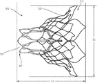
- FIGS. 10 and 11 are side and top views, respectively, of the outer frame of FIG. 9 in an expanded configuration.
- FIGS. 12-14 are side, front, and top views of an assembly of the inner frame of FIGS. 6-8 and the outer frame of FIGS. 9-11 .
- FIG. 15 is a side perspective view of an assembly of an inner frame and an outer frame shown in a biased expanded configuration, according to an embodiment.
- FIG. 16 is a side perspective view of the assembly of FIG. 15 with the outer frame shown inverted.
- FIG. 17 is side view of the assembly of FIG. 16 shown in a collapsed configuration within a lumen of a delivery sheath.
- FIG. 18 is a side view of the assembly of FIG. 17 shown in a first partially deployed configuration.
- FIG. 19 is a side view of the assembly of FIG. 17 shown in a second partially deployed configuration.
- FIG. 20 is a side view of the assembly of FIG. 17 shown in a third partially deployed configuration in which the inverted outer frame is substantially deployed outside of the delivery sheath.
- FIG. 21 is a side view of the assembly of FIG. 17 shown in a fourth partially deployed configuration in which the outer frame has reverted and assumed a biased expanded configuration.
- FIGS. 22-24 illustrate steps of a portion of a method to deliver the prosthetic valve of FIGS. 15-21 to an atrium of a heart and within the native mitral annulus.
- FIG. 25 is a schematic illustration of a delivery device and prosthetic heart valve, according to an embodiment.
- FIG. 26A is a side view of a portion of the prosthetic heart valve of FIG. 25 shown within a delivery sheath and coupled to a valve holder.
- FIG. 26B is a side view of an attachment member of the prosthetic valve of FIG. 26A .
- FIG. 26C is an end view of the valve holder of FIG. 26A .
- FIG. 27 is a cross-sectional side view of a prosthetic valve in an inverted configuration inside of a delivery sheath, according to an embodiment.
- FIG. 28 is a portion of a cross-sectional side view of a prosthetic valve in an inverted configuration inside of a delivery sheath, including a dilator, according to an embodiment.
- FIG. 29A is a cross-sectional side view of a prosthetic heart valve in an inverted configuration inside a lumen of a delivery sheath, according to an embodiment.
- FIG. 29B is a side view of the prosthetic heart valve of FIG. 9A in a reverted configuration and outside the delivery sheath.
- FIGS. 30A and 30B are schematic illustrations of a portion of a prosthetic heart valve, according to an embodiment, shown in a first configuration and a second configuration, respectively.
- FIGS. 30C and 30D are schematic illustrations of the portion of the prosthetic heart valve of FIGS. 30A and 30B , respectively, shown disposed within a delivery sheath.
- FIGS. 31A and 31B are schematic illustrations of the portion of a prosthetic heart valve of FIGS. 30A and 30B , shown in the first configuration and the second configuration, respectively.
- FIG. 32A is schematic illustration in side view of a delivery device and prosthetic heart valve, according to an embodiment.
- FIG. 32B is a schematic illustration of an end view of an elongate member of the delivery device of FIG. 32A .
- FIG. 33A is a cross-sectional side-view of a delivery sheath, with a prosthetic valve in an inverted configuration and disposed therein, according to an embodiment.
- FIG. 33B is an illustration in side view of the prosthetic heart valve of FIG. 33A in a reverted configuration and outside the delivery sheath.
- FIG. 33C is an illustration of an end view of the elongate member of the delivery device of FIG. 33A .
- FIG. 33D is an illustration of an end view of an elongate member of a delivery device, according to an embodiment.
- FIG. 34 is a partial cross-sectional side view of a delivery system and prosthetic heart valve, according to an embodiment.
- FIG. 35 is a cross-sectional view taken along line 35 - 35 in FIG. 34 showing the actuation wires coupled to a tube member of the delivery system.
- FIG. 36 is a proximal end view of a tube member of the delivery system of FIG. 34 .
- FIG. 37A is a side view of a portion of the tube member of FIG. 36 .
- FIG. 37B is a side view of a portion of a multi-lumen tube member according to another embodiment and a distal retention element according to an embodiment.
- FIG. 37C view of a portion of the multi-lumen tube member of FIG. 37B and a distal retention element, according to another embodiment.
- FIGS. 38A-38D are each a side view of a different embodiment of an actuation wire.
- FIG. 39 is a partial cross-sectional side view of the delivery system and prosthetic heart valve of FIG. 34 , shown in a first partially deployed configuration.
- FIG. 40 is a partial cross-sectional side view of the delivery system and prosthetic heart valve of FIG. 34 , shown in a second partially deployed configuration.
- FIG. 41 is a partial cross-sectional side view of the delivery system and prosthetic heart valve of FIG. 34 , shown in a third partially deployed configuration.
- FIG. 42 is a cross-sectional view taken along line A-A in FIG. 34 showing the actuation wires in a partially released position.
- FIG. 43 is a flowchart illustrating a method of delivering and deploying a prosthetic valve within a heart, according to an embodiment.
- FIG. 44 is a flowchart illustrating a method of delivering and deploying a prosthetic valve within a heart, according to an embodiment.
- a prosthetic valve includes an outer frame that can be inverted relative to an inner frame when the prosthetic valve is in a biased expanded configuration.
- the prosthetic mitral valve can be formed with, for example, a shape-memory material. After inverting the outer frame, the prosthetic valve can be inserted into a lumen of a delivery sheath such that the prosthetic valve is moved to a collapsed configuration.
- the delivery sheath can be used to deliver the prosthetic valve to within a patient's heart using a variety of different delivery approaches for delivering a prosthetic heart valve (e.g., prosthetic mitral valve) where the inverted prosthetic valve would enter the heart through the atrium of the heart.
- a prosthetic heart valve e.g., prosthetic mitral valve
- the prosthetic valves described herein can be delivered using a transfemoral delivery approach as described in PCT International Application No. PCT/US15/14572 (the “'572 PCT application”) and/or in PCT International Application No. PCT/US16/12305 (the “'305 PCT Application”), each disclosure of which is incorporated by reference in its entirety herein, or via a transatrial approach, such as described in U.S. Provisional Patent Application Ser. No.
- prosthetic valves described herein could be delivered via a transjugular approach, e.g., via the right atrium and through the atrial septum and into the left atrium, as described in U.S. Provisional Patent Application Ser. No. 62/305,678, entitled “Apparatus and Methods for Delivery of Prosthetic Mitral Valve,” (the “'678 provisional application”) and in U.S. Patent Application Pub. No.
- the prosthetic valves described herein can also be delivered apically if desired. With a transapical approach, after the delivery sheath has been disposed within the left atrium of the heart, the prosthetic mitral valve is moved distally out of the delivery sheath such that the inverted outer frame reverts and the prosthetic valve assumes its biased expanded configuration. The prosthetic mitral valve can then be positioned within a mitral annulus of the heart.
- an apparatus in some embodiments, includes a delivery sheath that defines a lumen, an elongate member that defines a first lumen and a second lumen and is at least partially disposed within the lumen of the delivery sheath.
- the apparatus further includes a prosthetic heart valve disposed at least partially within the lumen of the delivery sheath in a collapsed configuration and circumferentially about a portion of the elongate member.
- the prosthetic heart valve includes an outer frame coupled to an inner frame. The outer frame is movable between a first configuration relative to the inner frame and a second configuration relative to the inner frame in which the outer frame is inverted relative to the inner frame.
- the prosthetic heart valve is disposed within the lumen of the delivery sheath with the outer frame in the second configuration and disposed axially proximal to the inner frame.
- the apparatus further includes a first actuation wire releasably coupled to a first portion of the outer frame and routed from the first portion through the first lumen of the elongate member and out a proximal end portion of the delivery sheath.
- the apparatus further includes a second actuation wire releasably coupled to a second portion of the outer frame and routed from the second portion through the second lumen of the elongate member and out the proximal end portion of the delivery sheath.
- the first portion and the second portion of the outer frame are configured to be disposed within an atrium of a heart when implanted within the heart.
- a method includes inserting a distal end portion of a delivery sheath through an apical region of a heart and into an atrium of the heart.
- the delivery sheath has a prosthetic heart valve disposed within a lumen of the delivery sheath.
- the prosthetic heart valve includes an outer frame and an inner frame coupled to the outer frame.
- the outer frame is movable between a first position relative to the inner frame and a second position relative to the inner frame in which the outer frame is inverted relative to the inner frame.
- the prosthetic heart valve is disposed within the lumen of the delivery sheath with the outer frame in the second position relative to the inner frame during the inserting.
- the method further includes moving the prosthetic heart valve distally out of the delivery sheath.
- the method further includes causing the outer frame of the prosthetic heart valve to transition to the first position relative to the inner frame such that the prosthetic heart valve at least partially assumes a biased expanded configuration.
- the method further includes positioning the prosthetic heart valve within an annulus
- a method includes inserting a distal end portion of a delivery sheath into an atrium of a heart.
- the delivery sheath has a prosthetic heart valve disposed within a lumen of the delivery sheath.
- the prosthetic heart valve includes an outer frame and an inner frame coupled to the outer frame.
- the outer frame is movable between a first position relative to the inner frame and a second position relative to the inner frame in which the outer frame is inverted relative to the inner frame.
- the prosthetic heart valve is disposed within the lumen of the delivery sheath with the outer frame in the second position relative to the inner frame and disposed at least partially axially proximal to the inner frame during the inserting.
- the method further includes moving the prosthetic heart valve distally out of the delivery sheath.
- the method further includes causing the outer frame of the prosthetic heart valve to transition to the first position relative to the inner frame such that the prosthetic heart valve at least partially assumes a biased expanded configuration.
- the method further includes positioning the prosthetic heart valve within an annulus of the heart.
- an apparatus in some embodiments, includes an outer sheath that defines a lumen, a delivery sheath that defines a lumen and is movably disposed within the lumen defined by the outer sheath, and a prosthetic heart valve disposed within the lumen of the delivery sheath in a collapsed configuration.
- the prosthetic heart valve includes an outer frame coupled to an inner frame.
- the inner frame is removably coupled to a distal end portion of a valve holder.
- the outer frame is movable between a first configuration relative to the inner frame and a second configuration relative to the inner frame in which the outer frame is inverted relative to the inner frame.
- the prosthetic heart valve is disposed within the lumen of the delivery sheath with the outer frame in the second configuration.
- the apparatus further includes a first actuation wire releasably coupled to a first portion of the outer frame, and a second acutation wire releasably coupled to a second portion of the outer frame.
- Each of the first acutation wire and the second acutation wire has (1) a first portion extending proximally from the outer frame, through the lumen of the outer sheath, along an outside wall of the delivery sheaht, and through a first side aperture defined by the delivery sheath, and (2) a second portion extending proximally from the outer frame, through the lumen of the outer sheaht, along the outside all of the delivery sheaht, and through a second side aperture defined by the delivery sheath.
- the first portion and the second portion of each of the first acutation wire and the second acutation wire are configured to be pulled proximally to urge the outer frame from the second configuration towards the first configuration relative to the inner frame.
- an apparatus includes a prosthetic valve that includes an inner frame and an outer frame coupled to the inner frame at multiple coupling joints.
- the multiple coupling joints are configured to allow the outer frame to be moved relative to inner frame such that the prosthetic valve can be moved between a first configuration and a second configuration.
- the outer frame and the inner frame collectively define a first length of the prosthetic valve when the prosthetic valve is in the first configuration and a second length of the prosthetic valve when the prosthetic valve is in the second configuration and the second length is greater than the first length.
- the inner frame has a length that is the same when the prosthetic valve is in both the first configuration and the second configuration.
- an apparatus in some embodiments, includes a prosthetic heart valve that includes an inner frame and an outer frame coupled to the inner frame at multiple coupling joints.
- the prosthetic valve is movable between a first configuration and a second configuration.
- the multiple coupling joints are configured to allow the outer frame to be moved between a first position relative to the inner frame and a second position relative to inner frame in which the outer frame is inverted relative to the inner frame.
- the prosthetic valve is in the first configuration when the outer frame is in the first position, and in the second configuration when the outer frame is in the second position.
- an apparatus includes a prosthetic heart valve that includes an inner frame, and an outer frame coupled to the inner frame at multiple coupling joints.
- the multiple coupling joints are configured to allow the outer frame to be moved relative to inner frame such that the prosthetic valve can be moved between a first configuration and a second configuration.
- the outer frame has an outer frame coupling portion coupled to the inner frame at multiple coupling joints and an outer frame free end portion.
- the inner frame has an inner frame coupling portion coupled to the outer frame at the multiple coupling joints. A first end portion and an inner frame free end portion are on an opposite end of the inner frame from the first end portion.
- the multiple coupling joints are disposed between the outer frame free end portion and the first end portion of the inner frame when the prosthetic valve is in the first configuration.
- the multiple coupling joints are disposed between the inner frame free end portion and the outer frame free end portion when the prosthetic valve is in the second configuration.
- an apparatus includes a prosthetic heart valve that includes an inner frame coupled to an outer frame at multiple coupling joints.
- the multiple coupling joints are configured to allow the outer frame to be moved relative to inner frame such that the prosthetic valve can be moved between a first configuration and a second configuration.
- the outer frame has an outer frame coupling portion coupled to the inner frame at the multiple coupling joints and an outer frame free end portion.
- the inner frame has an inner frame coupling portion coupled to the outer frame at the multiple coupling joints and an inner frame free end portion.
- the outer frame free end portion and the inner frame free end portion each open in the same direction when the prosthetic valve is in the first configuration.
- the outer frame free end portion and the inner frame free end portion open in opposite directions when the prosthetic valve is in the second configuration.
- an apparatus in some embodiments, includes a delivery sheath that defines a lumen, a valve holder movably disposable within the lumen of the delivery sheath and a prosthetic heart valve disposed at least partially within the lumen of the delivery sheath in a collapsed configuration.
- the prosthetic heart valve includes an outer frame coupled to an inner frame and the inner frame is removably coupled to a distal end portion of the valve holder.
- the outer frame is movable between a first configuration relative to the inner frame and a second configuration relative to the inner frame in which the outer frame is inverted relative to the inner frame.
- the prosthetic heart valve is disposed within the lumen of the delivery sheath with the outer frame in the second configuration.
- a first actuation wire is releasably coupled to a first portion of an open free end portion of the outer frame and a second actuation wire is releasably coupled to a second portion of the open free end portion of the outer frame.
- Each of the first actuation wire and the second actuation wire have a first portion extending proximally from the outer frame and a second portion extending proximally from the outer frame.
- the first portion and the second portion of each of the first actuation wire and the second actuation wire are configured to be pulled proximally to urge the outer frame from the second configuration towards the first configuration relative to the inner frame.
- an apparatus in some embodiments, includes an outer sheath that defines a lumen, an inner sheath movably disposed within the lumen of the outer sheath and defining a lumen, a tube member movably disposed within the lumen of the outer sheath and defining a lumen, a valve holder movably disposed within the lumen of the inner sheath and within a lumen defined by the tube member and a prosthetic heart valve disposed at least partially within the lumen of the outer sheath and at least partially within the lumen of the inner sheath.
- the prosthetic heart valve includes an outer frame coupled to an inner frame and the inner frame is removably coupled to a distal end portion of the valve holder.
- the outer frame is movable between a first configuration relative to the inner frame and a second configuration relative to the inner frame in which the outer frame is inverted relative to the inner frame.
- the prosthetic heart valve is disposed within the lumen of the outer sheath and the lumen of the inner sheath with the outer frame in the second configuration.
- a first actuation wire is releasably coupled to a first portion of an open free end portion of the outer frame and releasably coupled to the tube member at a first location on the tube member.
- a second actuation wire is releasably coupled to a second portion of the open free end portion of the outer frame and releasably coupled to the tube member at a second location on the tube member.
- a method includes inserting a distal end portion of a delivery sheath into a left atrium of a heart.
- the delivery sheath having a prosthetic mitral valve disposed within a lumen of the delivery sheath and the prosthetic mitral valve has an outer frame coupled to an inner frame such that the outer frame can be moved between a first position relative to the inner frame and a second position relative to the inner frame in which the outer frame is inverted relative to the inner frame.
- the prosthetic valve is disposed within the lumen of the delivery sheath with the outer frame in the second position relative to the inner frame.
- the prosthetic mitral valve is moved distally out of the delivery sheath causing the outer frame of the prosthetic mitral valve to revert back to the first position relative to the inner frame such that the prosthetic mitral valve at least partially assumes a biased expanded configuration.
- the prosthetic mitral valve is positioned within a mitral annulus of the heart.
- FIGS. 1A and 1B are schematic illustrations of a portion of a prosthetic heart valve 100 , according to an embodiment, shown in a first configuration and a second configuration respectively, and FIGS. 1C and 1D illustrate the portions of the prosthetic heart valve 100 of FIGS. 1A and 1B , respectively, shown disposed within a lumen of a delivery sheath 126 .
- FIGS. 2A and 2B illustrate a portion of the prosthetic heart valve 100 of FIGS. 1A and 1B , respectively, and show length dimensions for the prosthetic heart valve in each of the first configuration and the second configuration.
- the size of the prosthetic valve during delivery should be sized accordingly.
- a prosthetic valve that can be reconfigured between a biased expanded configuration for implantation in the heart (e.g., within a native mitral annulus) and a delivery configuration that has a smaller outer perimeter or profile to allow for delivery within the lumen of the delivery sheath.
- the prosthetic valve 100 and the embodiments of a prosthetic valve described herein can be constructed and formed to achieve these desired functions and characteristics.
- the prosthetic heart valve 100 (also referred to herein as “prosthetic valve” or “valve”) can be, for example, a prosthetic mitral valve.
- the valve 100 includes an outer frame 120 and an inner frame 150 .
- the outer frame 120 and the inner frame 150 are each formed as a tubular structure as described in more detail below with reference to FIGS. 3-15 .
- the outer frame 120 and the inner frame 150 can be coupled together at multiple coupling joints 146 disposed about a perimeter of the inner frame 150 and a perimeter of the outer frame 120 as described in more detail below.
- the valve 100 can also include other features, such as those described with respect to FIGS. 3-15 below. For illustration purposes, only the inner frame 150 and the outer frame 120 are discussed with respect to FIGS. 1A-2B .
- the various characteristics and features of valve 100 described with respect to FIGS. 1A-2B can apply to any of the prosthetic valves described here.
- the outer frame 120 is configured to have a biased expanded or undeformed shape and can be manipulated and/or deformed (e.g., compressed or constrained) and, when released, return to its original (expanded or undeformed) shape.
- the outer frame 120 can be formed of materials, such as metals or plastics, which have shape memory properties.
- metals Nitinol® has been found to be especially useful since it can be processed to be austenitic, martensitic or super elastic.
- Other shape memory alloys such as Cu—Zn—Al—Ni alloys, and Cu—Al—Ni alloys, may also be used.
- the inner frame 150 can be formed from a laser-cut tube of Nitinol®.
- the inner frame 150 can also have a biased expanded or undeformed shape and can be manipulated and/or deformed (e.g., compressed and/or constrained) and, when released, return to its original (expanded or undeformed) shape. Further details regarding the inner frame 150 and the outer frame 120 are described below with respect to valve 200 and FIGS. 3-15 .
- the valve 100 can be delivered and deployed within a left atrium of a heart using a variety of different delivery approaches including, for example, a transfemoral delivery approach, as described in the '572 PCT application and/or in the '305 PCT application, or a transatrial or transjugular approach, as described in the '704 provisional application, the '678 provisional application and the '790 publication”) incorporated by reference above.
- a transfemoral delivery approach as described in the '572 PCT application and/or in the '305 PCT application
- a transatrial or transjugular approach as described in the '704 provisional application, the '678 provisional application and the '790 publication
- a prosthetic valve that can be reconfigured between a biased expanded configuration for implantation in the heart (e.g., within a native mitral annulus) and a delivery configuration that has a smaller outer perimeter or profile to allow for delivery within the lumen of the delivery sheath.
- the prosthetic valve 100 and the embodiments of a prosthetic valve described herein can be constructed and formed to achieve these desired functions and characteristics.
- the valve 100 can have a biased expanded configuration (as shown in FIGS. 1A and 2A ), an inverted configuration (as shown in FIGS. 1B and 2B ), and a compressed or collapsed configuration (as shown in FIGS. 1C and 1D ).
- the expanded configuration allows the valve 100 to function when implanted within the heart.
- the valve 100 can be moved to the inverted configuration and the compressed or collapsed configuration for delivery of the valve 100 to the heart of a patient.
- the outer frame 120 can be coupled to the inner frame 150 in such a manner to allow the outer frame 120 to move relative to the inner frame 150 .
- the coupling joints 146 can couple the outer frame 120 to the inner frame 150 in such a manner to allow the outer frame 120 to be moved relative to the inner frame 150 .
- the coupling joints 146 can be configured to allow the outer frame 120 to rotate about the coupling joint 146 relative to the inner frame 150 .
- coupling joints can provide a pivotal coupling between the outer frame 120 and the inner frame 150 .
- the coupling joints can provide a flexible attachment between the outer frame 120 and the inner frame 150 .
- the coupling joints 146 can be a variety of different types and configurations as described herein with reference to the various embodiments of a prosthetic valve.
- the coupling joints 146 can include a living hinge, a flexible member, sutures, a suture wrapped through an opening, a pin or tab inserted through an opening or any combinations thereof.
- the outer frame 120 is moved to a prolapsed or inverted configuration relative to the inner frame 150 , as shown in FIGS. 1B, 1D and 2B , by moving (e.g., rotating, pivoting, flexing) the outer frame 120 about the coupling joints 146 .
- the elastic or superelastic structure of outer frame 120 of valve 100 also allows the outer frame 120 to be moved to, and disposed in, the prolapsed or inverted configuration relative to the inner frame 150 .
- the outer frame 120 is folded or inverted distally (to the right in FIG.
- the outer frame 120 is in a first position relative to the inner frame 150 prior to being inverted in which an open or free end portion 116 (also referred to the atrium portion 116 of the outer frame 120 ) is disposed proximally or to the left of the coupling joints 146 and in the same direction as a free end portion 147 (also referred to as a second end portion of the inner frame) of the inner frame 150 .
- an open or free end portion 116 also referred to the atrium portion 116 of the outer frame 120
- a free end portion 147 also referred to as a second end portion of the inner frame
- the coupling joints 146 are disposed between a first end portion 144 (also referred to as a tether coupling portion) of the inner frame 150 and the free end portion 116 of the outer frame 120 .
- the coupling joints 146 are disposed between the free end portion or second end portion 147 of the inner frame 150 and the free end portion 116 of the outer frame 120 .
- an overall length of the valve 100 is increased, but a length of the inner frame 150 and a length of the outer frame 120 remains the same (or substantially the same).
- an overall length L 1 of the valve 100 in the biased expanded configuration is less than the overall length L 2 of the valve 100 when in the inverted configuration ( FIG. 2B ).
- a length Li of the inner frame 150 and a length Lo of the outer frame 120 is substantially the same (or the same) when the valve 100 is in both the biased expanded configuration and the inverted configuration.
- an overall outer perimeter or outer diameter of the valve 100 can be smaller when the valve 100 is in the inverted configuration.
- valve 100 With the valve 100 in the inverted configuration, the valve 100 can be placed within a lumen of the delivery sheath 126 for delivery of the valve 100 to the left atrium of the heart, as shown in FIG. 1D .
- the valve 100 When placed within the lumen of the delivery sheath 126 , the valve 100 is moved to the collapsed or compressed configuration in which the outer diameter or outer perimeter of the valve 100 is reduced. Because the valve 100 is in the inverted configuration, the valve 100 is able to be placed within a smaller delivery sheath 126 than would otherwise be possible. For example, for comparison purposes, FIG.
- FIG. 1C illustrates the valve 100 placed within a lumen of a delivery sheath 126 ′ where the valve 100 has not been moved to an inverted configuration prior to being disposed within the delivery sheath 126 ′.
- an outer diameter of the valve 100 is reduced, but not to as small of a diameter as for the valve 100 when placed in a delivery sheath 126 when in the inverted configuration.
- the valve 100 has an overall outer perimeter or outer diameter D 1 and in FIG. 1D , the valve 100 has an overall outer perimeter or outer diameter D 2 , which is less than D 1 .
- the valve 100 can be collapsed into a smaller overall diameter, i.e. placed in a smaller diameter delivery sheath 126 , than would be possible if the valve 100 were merely collapsed radially.
- the inner frame 150 is nested within an interior of the outer frame 120 , and thus the outer frame 120 must be collapsed around the inner frame 150 .
- the inner frame 150 and the outer frame are disposed concentrically.
- the inner frame 150 and the outer frame 120 are arranged axially with respect to each other (i.e., the inner frame is not nested within the outer frame 150 ), such that the outer frame 120 can be collapsed without needing to accommodate all of the structure of the inner frame 150 inside it.
- the inner frame 150 disposed mostly inside or nested within the outer frame 120 , the layers or bulk of the frame structures cannot be compressed to as small a diameter.
- the structure is less flexible, and therefore, more force is needed to bend the valve, e.g. to pass through tortuous vasculature or to make tight turn in the left atrium after passing through the atrial septum to be properly oriented for insertion into the mitral valve annulus.
- FIGS. 3-14 illustrate another embodiment of a prosthetic heart valve that can be delivered and deployed within a left atrium of a heart using a variety of different delivery approaches including, for example, a transfemoral delivery approach or a transatrial delivery approach.
- FIGS. 3-5 are front, bottom, and top views, respectively, of a prosthetic heart valve 200 according to an embodiment.
- Prosthetic heart valve 200 (also referred to herein as “valve” or “prosthetic valve”) is designed to replace a damaged or diseased native heart valve such as a mitral valve.
- Valve 200 includes an outer frame assembly 210 and an inner valve assembly 240 coupled to the outer frame assembly 210 .
- outer frame assembly 210 includes an outer frame 220 , covered on all or a portion of its outer face with an outer covering 230 , and covered on all or a portion of its inner face by an inner covering 232 .
- Outer frame 220 can provide several functions for prosthetic heart valve 200 , including serving as the primary structure, as an anchoring mechanism and/or an attachment point for a separate anchoring mechanism to anchor the valve to the native heart valve apparatus, a support to carry inner valve assembly 240 , and/or a seal to inhibit paravalvular leakage between prosthetic heart valve 200 and the native heart valve apparatus.
- Outer frame 220 has a biased expanded configuration and can be manipulated and/or deformed (e.g., compressed and/or constrained) and, when released, return to its original unconstrained shape.
- outer frame 220 can be formed of materials, such as metals or plastics, which have shape memory properties.
- metals such as metals or plastics, which have shape memory properties.
- Nitinol® has been found to be especially useful since it can be processed to be austenitic, martensitic or super elastic.
- Other shape memory alloys such as Cu—Zn—Al—Ni alloys, and Cu—Al—Ni alloys, may also be used.
- outer frame assembly 210 has an upper end (e.g., at the atrium portion 216 ), a lower end (e.g., at the ventricle portion 212 ), and a medial portion (e.g., at the annulus portion 214 ) therebetween.
- the upper end or atrium portion 216 (also referred to as “outer free end portion”) defines an open end portion of the outer frame assembly 210 .
- the medial or annulus portion 214 of the outer frame assembly 210 has a perimeter that is configured (e.g., sized, shaped) to fit into an annulus of a native atrioventricular valve.
- the upper end of the outer frame assembly 210 has a perimeter that is larger than the perimeter of the medial portion.
- the perimeter of the upper end of the outer frame assembly 210 has a perimeter that is substantially larger than the perimeter of the medial portion. As shown best in FIG. 5 , the upper end and the medial portion of the outer frame assembly 210 has a D-shaped cross-section. In this manner, the outer frame assembly 210 promotes a suitable fit into the annulus of the native atrioventricular valve.
- Inner valve assembly 240 includes an inner frame 250 , an outer covering (not shown), and leaflets 270 . As shown, the inner valve assembly 240 includes an upper portion having a periphery formed with multiple arches.
- the inner frame 250 includes six axial posts or frame members that support the outer covering of the inner valve assembly 240 and leaflets 270 .
- Leaflets 270 are attached along three of the posts, shown as commissure posts 252 (best illustrated in FIG. 4 ), and the outer covering of the inner valve assembly 240 is attached to the other three posts, 254 (best illustrated in FIG. 4 ), and optionally to commissure posts 252 .
- Each of outer covering of the inner valve assembly 240 and leaflets 270 are formed of approximately rectangular sheets of material, which are joined together at their upper, or atrium end.
- the lower, ventricle end of the outer covering of the inner valve assembly 240 may be joined to inner covering 232 of outer frame assembly 210 , and the lower, ventricle end of leaflets 270 may form free edges 275 , though coupled to the lower ends of commissure posts 252 .
- inner valve assembly 240 is shown as having three leaflets, in other embodiments, an inner valve assembly can include any suitable number of leaflets.
- the leaflets 270 are movable between an open configuration and a closed configuration in which the leaflets 270 coapt, or meet in a sealing abutment.
- Outer covering 230 of the outer frame assembly 210 and inner covering 232 of outer frame assembly 210 , outer covering 260 of the inner valve assembly 240 and leaflets 270 of the inner valve assembly 240 may be formed of any suitable material, or combination of materials, such as those discussed above.
- the inner covering 232 of the outer frame assembly 210 , the outer covering of the inner valve assembly 240 , and the leaflets 270 of the inner valve assembly 240 are formed, at least in part, of porcine pericardium.
- the outer covering 230 of the outer frame assembly 210 is formed, at least in part, of polyester.
- FIGS. 6-8 show inner frame 250 in an undeformed, initial state ( FIG. 6 ), a side view of the inner frame 250 in an expanded configuration ( FIG. 7 ), and a bottom view of the inner frame 250 in the expanded configuration ( FIG. 8 ), respectively, according to an embodiment.
- inner frame 250 is formed from a laser-cut tube of Nitinol®.
- Inner frame 250 is illustrated in FIG. 6 in an undeformed, initial state, i.e. as laser-cut, but cut and unrolled into a flat sheet for ease of illustration.
- Inner frame 250 can be divided into four portions, corresponding to functionally different portions of the inner frame 250 in final form: atrial portion 247 , body portion 242 , strut portion 243 , and tether clamp or connecting portion 244 .
- Strut portion 243 includes six struts, such as strut 243 A, which connect body portion 242 to tether connecting portion 244 .
- Tether connecting portion 244 (also referred to as first end portion of inner frame) includes longitudinal extensions of the struts, connected circumferentially by pairs of opposed, slightly V-shaped connecting members (or “micro-Vs”). Tether connecting portion 244 is configured to be radially collapsed by application of a compressive force, which causes the micro-Vs to become more deeply V-shaped, with the vertices moving closer together longitudinally and the open ends of the V shapes moving closer together circumferentially. Thus, tether connecting portion 244 can be configured to compressively clamp or grip one end of a tether, either connecting directly onto a tether line (e.g. braided filament line) or onto an intermediate structure, such as a polymer or metal piece that is in term firmly fixed to the tether line.
- a tether line e.g. braided filament line
- intermediate structure such as a polymer or metal piece that is in term firmly fixed to the tether line.
- Atrial portion 247 (also referred to as “inner frame free end portion”) and body portion 242 are configured to be expanded radially.
- Strut portion 243 forms a longitudinal connection and radial transition between the expanded body portion and the compressed tether connecting portion 244 .
- Body portion 242 provides an inner frame coupling portion 245 that includes six longitudinal posts, such as post 242 A.
- the inner frame coupling portion 245 can be used to attach leaflets 270 to inner frame 240 , and/or can be used to attach inner assembly 240 to outer assembly 210 , such as by connecting inner frame 250 to outer frame 220 .
- the posts include openings through which connecting members (such as suture filaments and/or wires) can be passed to couple the posts to other structures.
- Inner frame 250 is shown in a fully deformed, i.e. the final, deployed configuration, in side view and bottom view in FIGS. 7 and 8 , respectively.
- Outer frame 220 of valve 200 is shown in more detail in FIGS. 9-11 .
- outer frame 220 is also formed from a laser-cut tube of Nitinol®.
- Outer frame 220 is illustrated in FIG. 9 in an undeformed, initial state, i.e. as laser-cut, but cut and unrolled into a flat sheet for ease of illustration.
- Outer frame 220 can be divided into an outer frame coupling portion 271 , a body portion 272 , and a cuff portion 273 (which includes the atrium or free end portion 216 ), as shown in FIG. 9 .
- Outer frame coupling portion 271 includes multiple openings or apertures, such as 271 A, by which outer frame 220 can be coupled to inner frame 250 , as discussed in more detail below.
- Outer frame 220 is shown in a fully deformed, i.e. the final, deployed configuration, in side view and top view in FIGS. 10 and 11 , respectively.
- the lower end of outer frame coupling portion 271 forms a roughly circular opening (identified by “O” in FIG. 11 ).
- the diameter of this opening preferably corresponds approximately to the diameter of body portion 242 of inner frame 250 , to facilitate coupling of the two components of valve 200 .
- Outer frame 220 and inner frame 250 are shown coupled together in FIGS. 12-14 , in front, side, and top views, respectively.
- the two frames collectively form a structural support for a prosthetic valve such as valve 200 .
- the frames support the valve leaflet structure (e.g., leaflets 270 ) in the desired relationship to the native valve annulus, support the coverings (e.g., outer covering 230 , inner covering 232 , outer covering of inner valve assembly 240 ) for the two frames to provide a barrier to blood leakage between the atrium and ventricle, and couple to the tether (e.g., tether assembly 290 ) (by the inner frame 250 ) to aid in holding the prosthetic valve 200 in place in the native valve annulus by the tether connection to the ventricle wall.
- the tether e.g., tether assembly 290
- the outer frame 220 and the inner frame 250 are connected at six coupling points (representative points are identified as “C”).
- the coupling points are implemented with a mechanical fastener, such as a short length of wire, passed through an aperture (such as aperture 271 A) in outer frame coupling portion 271 and corresponding openings in inner frame coupling portion 245 (e.g., longitudinal posts, such as post 242 A) in body portion 242 of inner frame 250 .
- Inner frame 250 is thus disposed within the outer frame 220 and securely coupled to it.
- FIGS. 15-21 illustrate a method of reconfiguring a prosthetic heart valve 300 (e.g., prosthetic mitral valve) prior to inserting the prosthetic heart valve 300 into a delivery sheath 326 (see, e.g., FIGS. 17-21 ) for delivery into the atrium of the heart.
- the prosthetic heart valve 300 (also referred to herein as “valve”) can be constructed the same as or similar to, and function the same as or similar to the valves 100 and 200 described above. Thus, some details regarding the valve 300 are not described below. It should be understood that for features and functions not specifically discussed, those features and functions can be the same as or similar to the valve 200 .
- the valve 300 has an outer frame 320 and an inner frame 350 .
- the outer frame 320 and the inner frame 350 of valve 300 can each be formed with a shape-memory material and have a biased expanded configuration.
- the outer frame 320 and the inner frame 350 can be moved to a collapsed configuration for delivery of the valve 300 to the heart.
- the outer frame 320 of the valve 300 is first disposed in a prolapsed or inverted configuration as shown in FIG. 16 .
- the elastic or superelastic structure of outer frame 320 of valve 300 allows the outer frame 320 to be disposed in the prolapsed or inverted configuration prior to the valve 300 being inserted into the lumen of the delivery sheath 326 .
- the outer frame 320 is folded or inverted distally (to the right in FIG. 16 ) such that an open free end 316 of the outer frame 320 is pointed away from an open free end 347 of the inner frame 350 .
- the overall outer perimeter or outer diameter of the valve 300 is reduced and the overall length is increased.
- the diameter D 1 shown in FIG. 15 is greater than the diameter D 2 shown in FIG.
- the valve 300 With the outer frame 320 in the inverted configuration relative to the inner frame 350 , the valve 300 can be placed within a lumen of a delivery sheath 326 as shown in FIG. 17 for delivery of the valve 300 to the left atrium of the heart. By disposing the outer frame 320 in the inverted configuration relative to the inner frame 350 , the valve 300 can be collapsed into a smaller overall diameter, i.e. when placed in a smaller diameter delivery sheath, than would be possible if the valve 300 in the configuration shown in FIG. 15 were collapsed radially without being inverted. This is because in the configuration shown in FIG.
- the two frames are concentric or nested, and thus the outer frame 320 must be collapsed around the inner frame 350 , whereas in the configuration shown in FIG. 16 , the two frames are substantially coaxial but not concentric or nested.
- the outer frame 320 can be collapsed without the need to accommodate the inner frame 350 inside of it.
- the layers or bulk of the frame structures cannot be compressed to as small a diameter.
- the structure is less flexible, and therefore, more force is needed to bend the valve, e.g. to pass through tortuous vasculature or to make tight turn in the left atrium after passing through the atrial septum to be properly oriented for insertion into the mitral valve annulus.
- FIGS. 22-24 illustrate a portion of a procedure to deliver the valve 300 to the heart.
- the valve 300 is shown being delivered via a transfemoral delivery approach as described, for example, in the '572 PCT application and/or in the '305 PCT Application incorporated by reference above.
- the delivery sheath 326 with the valve 300 disposed within a lumen of the delivery sheath 326 and in an inverted configuration as shown in FIG. 17 , can be inserted into a femoral puncture, through the femoral vein, through the inferior vena cava, into the right atrium, through the septum Sp and into the left atrium LA of the heart.
- the valve 300 can be deployed outside a distal end of the delivery sheath 326 .
- a pusher device 338 can be used to move or push the valve 300 out the distal end of the delivery sheath 326 .
- a tether 336 can be attached to the valve 300 , and extend though the mitral annulus, through the left ventricle LV, and out a puncture site at the apex Ap.
- the valve 300 can be moved out of the delivery sheath 326 by pulling proximally on the tether 336 .
- the valve 300 can be deployed by pushing with the pusher device and pulling with the tether.
- the outer frame assembly 310 exits first in its inverted configuration as shown in the progression of FIGS. 18-20 (see also FIG. 22 ).
- the outer frame 320 can revert to its expanded or deployed configuration as shown in FIGS. 21, 23 and 24 .
- the outer frame 320 can revert automatically after fully exiting the lumen of the delivery sheath due to its shape-memory properties.
- a component of the delivery sheath or another device can be used to aid in the reversion of the outer frame assembly 310 .
- the pusher device and/or the tether can be used to aid in the reversion of the outer frame assembly 310 .
- the valve 300 can continue to be deployed until the inner frame 350 is fully deployed with the left atrium and the valve 300 is in the expanded or deployed configuration (as shown, e.g., in FIGS. 15 and 24 ).
- the valve 300 and the tether 336 can then be secured to the apex of the heart with an epicardial pad device 339 as shown in FIG. 24 and as described in more detail in the '572 PCT application and the '305 PCT application.
- FIG. 25 illustrates schematically another embodiment of a delivery system that can be used to delivery and deploy a prosthetic heart valve within a heart of a patient with, for example, a transvascular approach.
- a delivery system 405 includes a delivery sheath 426 , a valve holder 438 (also referred to as a “pusher”), and one or more actuation wires 474 and 476 .
- actuation wires 474 and 476 In this schematic illustration, only two actuation wires are illustrated, but in other embodiments, only one actuation wire or more than two actuation wires can be used.
- the delivery sheath 426 can be used to deliver a valve 400 that includes an inner valve assembly 440 including an inner frame (not labeled in FIG. 25 ) and an outer frame assembly 410 including an outer frame (not labeled in FIG. 25 ).
- the valve 400 can be constructed the same as or similar to, and function the same as or similar to, for example, any of the prosthetic valves described herein and/or in the '305 PCT Application, and can be moved between a deployed or expanded configuration and a delivery configuration in which the outer frame is disposed in an inverted position relative to the inner frame as described herein and/or in the '305 PCT Application. As shown in FIG.
- the valve 400 can be disposed within a lumen of the delivery sheath 426 when the valve is in the delivery configuration (i.e., the outer frame is inverted relative to the inner frame).
- the outer frame assembly 410 when in the delivery configuration and placed within a delivery sheath, the outer frame assembly 410 is disposed distal of the inner valve assembly 440 .
- the valve holder 438 is coupled to the inner valve assembly 440 and the actuation wires are coupled to the outer fame assembly 410 .
- the valve holder 438 can be releasably coupled to the inner valve assembly 440 via couplers 406 that are attached to the inner valve assembly 440 as shown in FIGS. 26A-26C .
- the couplers 406 are in the form of a T-bar or hammer shape. It should be understood that couplers with other configurations and shapes can be used.
- the couplers 406 are received within the recesses 404 and the valve 400 and the valve holder 438 can be disposed within the lumen of the delivery sheath 426 .
- the inner diameter of the delivery sheath 426 can be sized such that when the valve holder 438 and valve 400 are disposed therein, the couplers 406 are unable to exit the recesses 404 .
- the inner walls of the delivery sheath 426 maintain the couplers 406 within the recesses 404 .
- the couplers 406 will be able to freely exit the recesses 404 releasing the inner frame 450 from the valve holder 438 .
- valve holder 438 can be removably coupled to the valve 400 (e.g., the inner frame 450 of the valve 400 ) via wires or sutures that can be cut after delivery of the valve 400 to the heart.
- the valve holder 438 can be decoupled from the valve 400 when the valve is still disposed within the delivery sheath 426 , while in other instances the valve holder 438 can be decoupled from the valve 400 after the valve 400 exits the delivery sheath 426 within the heart.
- the actuation wires 474 and 476 can be coupled to the outer frame of the outer frame assembly 410 with a variety of different coupling methods.
- the outer frame 410 can include loops (as described herein with respect to outer frame 510 , outer frame 1010 , and in the '305 PCT Application) through which the actuation wires 474 and 476 can be received or threaded.
- the number of loops on the outer frame can vary and the number of loops through which each actuation wire is connected can vary.
- the outer frame includes 12 loops and a first actuation wire is threaded through 6 of the loops and a second actuation wire is threaded through 6 of the loops.
- the outer frame can include 12 loops and there can be 4 actuation wires, each coupled to 3 of the loops.
- a single actuation wire is coupled through all of the loops of the outer frame.
- the delivery sheath 426 can be used to deliver the valve 400 to the left atrium of the heart using a transvascular approach (e.g., transfemoral, transatrial, transjugular).
- a transvascular approach e.g., transfemoral, transatrial, transjugular.
- the valve 400 is moved out of the lumen of the delivery sheath 426 using the actuation wires 474 , 476 to assist in pulling the valve 400 out of the delivery sheath 426 .
- the valve holder 438 can also be used to push the valve 400 out of the delivery sheath 426 .
- the actuation wires 474 and 476 can extend from the outer frame assembly 410 out a distal end of the delivery sheath and extend proximally.
- the actuation wires 474 , 476 extend proximally outside the delivery sheath 426 , then pass back into the lumen of the delivery sheath 426 through side apertures or holes (not shown) and then out a proximal end of the delivery sheath 426 .
- a user e.g., physician
- the actuation wires 474 , 476 extend proximally from the outer frame assembly 410 , back through the distal end of the delivery sheath 426 (e.g., rather than through side apertures or holes of the delivery sheath) and within the lumen of the delivery sheath, and then out a proximal end of the delivery sheath 426 .
- the actuation wires 474 , 476 extend proximally from the outer frame assembly 410 , back through the distal end of the delivery sheath 426 (e.g., rather than through side apertures or holes of the delivery sheath) and within the lumen of the delivery sheath, and then out a proximal end of the delivery sheath 426 .
- the outer frame assembly 410 As the outer frame assembly 410 exits the delivery sheath 426 it will still be in an inverted configuration relative to the inner valve assembly 440 . After the outer frame assembly 410 is at least partially outside of the lumen of the delivery sheath 426 , the outer frame assembly 410 can begin to revert to its expanded or deployed configuration (not shown in FIG. 25 ). In this embodiment, however, the actuation wires 474 and 476 can function to selectively (e.g., by an operator) assist and/or control the expansion, deployment and/or articulation of the valve 400 as the valve 400 is delivered to the heart.
- the proximal end portions of the actuation wires 474 , 476 can be pulled distally to manipulate the outer frame assembly 410 to assist and control the transition of the outer frame assembly 410 from its inverted configuration relative to the inner valve assembly 440 to its expanded or deployed configuration (not shown).
- the actuation wires 474 , 476 can be manually grasped by a user to pull the actuation wires proximally.
- the actuation wires 474 , 476 can be operatively coupled to the delivery system 405 such that the user does not have to manually handle the actuation wires.
- the actuation wires can be coupled to a delivery sheath and/or to a handle assembly (not shown) of the delivery system 405 .
- a delivery sheath and/or to a handle assembly (not shown) of the delivery system 405 .
- a handle assembly not shown
- Various embodiments of a delivery system are described in more detail below and in the '305 PCT Application.
- FIG. 27 illustrates an embodiment of a delivery system 505 that can be used to deliver and deploy a prosthetic heart valve 500 (also referred to herein as “valve”) within a heart in a procedure similar to or the same as the procedures described with respect to other embodiments described herein (e.g., the embodiments illustrated in and described with respect to FIGS. 34-42 ) and embodiments described in the '305 PCT Application.
- a prosthetic heart valve 500 also referred to herein as “valve”
- FIG. 27 illustrates an embodiment of a delivery system 505 that can be used to deliver and deploy a prosthetic heart valve 500 (also referred to herein as “valve”) within a heart in a procedure similar to or the same as the procedures described with respect to other embodiments described herein (e.g., the embodiments illustrated in and described with respect to FIGS. 34-42 ) and embodiments described in the '305 PCT Application.
- valve also referred to herein as “valve”
- the valve 500 can be constructed the same as or similar to, and function the same as or similar to any of the valves described herein and/or in the '305 PCT Application.
- the valve 500 includes an outer frame assembly that has an outer frame 520 , an inner valve assembly 540 that has an inner frame 550 , and a tether 536 coupled to the inner valve assembly.
- the delivery system 505 includes an outer delivery sheath 526 , an inner sheath 508 , a valve holder 538 (also referred to as a “pusher”) and a multi-lumen elongate tube member 503 (also referred to as “tube” or “tube member” or “multi-lumen elongate member”). As shown in FIG.
- the inner sheath 508 is movably disposed within the lumen 582 defined by the outer delivery sheath 526
- the tube member 503 is movably disposed within a lumen 583 defined by the inner sheath 508
- the valve holder 538 is movably disposed the lumen 583 defined by the inner sheath 508 .
- the valve 500 can be moved from a biased expanded configuration to an inverted configuration for delivery of the valve 500 to the heart. More specifically, to place the valve 500 in the inverted configuration, the outer frame 520 can be moved to an inverted configuration relative to the inner frame 550 . In this embodiment, the valve 500 is placed at least partially within the lumen of the inner sheath 508 when the valve 500 is in the inverted configuration, and disposed near a distal end of the inner sheath 508 . The valve holder 538 is also disposed within the lumen 583 of the inner sheath 508 .
- the inner frame 550 can be releasably coupled to the valve holder 538 with couplers 506 in the same or similar manner as described above with respect to couplers 406 , couplers 1006 , and/or any of the couplers described in the '305 PCT Application.
- the outer frame 520 includes loops 562 through which actuation wires 574 - 577 can be threaded through in the same or similar manner as described herein (e.g., with respect to valve 1000 ) and/or in the '305 PCT Application.
- the inner sheath 508 is movably disposed within the outer delivery sheath 526 . As shown in FIG.
- a portion of the valve 500 is disposed outside of the inner sheath 508 and within the lumen 582 of the outer delivery sheath 526 .
- the entire valve 500 can be disposed within the lumen 583 of the inner sheath 508 prior to performing the procedure to deploy the valve.
- the inner sheath 508 defines side apertures 509 through which the actuation wires 574 - 577 can pass through. More specifically, as shown in FIG. 27 , when the valve 500 is disposed within the lumen 583 of the inner sheath 508 , the actuation wires 574 - 577 extend proximally from the outer frame 520 , along the outside of the inner sheath 508 and within the lumen 582 of the outer delivery sheath 526 , back through side apertures 509 defined by the inner sheath 508 , within the lumen 583 of the inner sheath 508 , and are pinned by an elongate pinning member 578 - 1 , 578 - 2 , 578 - 3 , 578 - 4 (collectively referred to as pinning member 578 ; pinning members 578 - 3 and 578 - 4 are not shown in FIG.
- a first end of the actuation wire 574 and a first end of the actuation wire 575 are pinned by a pinning member 578 - 2
- a first end of the actuation wire 576 and a first end of the actuation wire 577 are pinned by a pinning member 578 - 1 .
- a second end of the actuation wire 574 and a second end of the actuation wire 576 are pinned by a pinning member 578 - 4 (not shown), and a second end of the actuation wire 575 and a second end of the actuation wire 577 are pinned by a pinning member 578 - 3 (not shown).
- the actuation wires 574 - 577 can be pinned to the tube member 503 by the pinning members 578 - 1 , 578 - 2 , 578 - 3 , 578 - 4 in the same or similar manner as described below with respect to the delivery system 1005 .
- some details regarding, for example, the tube member 503 , the pinning member 578 - 1 , 578 - 2 , 578 - 3 , 578 - 4 and the actuation wires 574 - 577 , and procedures performed therewith, are not described with respect to this embodiment. It should be understood that for features and functions not specifically discussed with respect to this embodiment, those features and functions can be the same as or similar to the delivery systems described in herein (e.g., the delivery system 1005 ) and/or in the '305 PCT Application.
- a user can use the tube member 503 , to which the actuation wires 574 - 577 are coupled, to control and/or manipulate movement and/or deployment of the valve 500 as described, for example, with respect to the delivery system 1005 .
- at least a portion of the actuation wires 574 - 577 can be disposed within the interior of the delivery sheath 526 , thus limiting the exposure of the actuation wires 574 - 577 to areas external to the delivery sheath 526 for at least a portion of the delivery and/or deployment of the valve 500 .
- side apertures 509 defined by the inner sheath 508 are shown as disposed at or near the distal end portion of the inner sheath 508 , in other embodiments, side apertures 509 can be disposed at any suitable location along the length of the inner sheath 508 (e.g., towards a middle portion or a proximal portion of the management sheath).
- the distal end of the outer delivery sheath 526 with the valve 500 , inner sheath 508 , valve holder 538 , and tube member 503 disposed therein, is disposed within the left atrium of the heart.
- the valve 500 can be deployed outside of the delivery sheath 526 .
- the inner sheath 508 , valve holder 538 , and tube member 503 can be moved distally relative to the outer sheath 526 , moving or pushing the valve 500 outside the lumen 582 of the outer sheath 526 .
- the outer sheath 526 can be moved or pulled proximally, leaving at least a portion of the valve 500 disposed within the heart.
- the tether 536 coupled to the valve 500 can be used to help pull the valve 500 out of the lumen 582 of the outer sheath 526 .
- the outer frame 520 can begin to revert to its expanded or uninverted configuration.
- the actuation wires 575 - 577 can be used to control the reversion of the outer frame 520 . More specifically, after the outer frame 520 is disposed at least partially outside the distal end of the outer sheath 526 , the tube member 503 can be pulled proximally such that the actuation wires (pinned to the tube member 503 ) pull the distally disposed portion of the outer frame 520 proximally (the same as or similar to as shown in FIG. 40 ) in a controlled manner and such that the reversion of the outer frame 520 from its inverted configuration relative to the inner frame 550 can be controlled.
- the actuation wires 574 - 577 can assist in the articulation and placement of the valve 500 into its destination (e.g., a native annulus of an atrioventricular valve of a heart).
- the actuation wires 574 - 577 can also be used to constrain, collapse, or otherwise move the valve 500 (e.g., radially compress the outer frame 520 of the valve 500 ) after the valve 500 exits the outer sheath 526 and is in its reverted, expanded or partially expanded configuration.
- the tube member 503 with the actuation wires 574 - 577 pinned thereto can be manipulated by a user to move or urge the outer frame 520 to a more compressed configuration (similar to or the same as shown in FIG. 41 ) by pulling or moving the tube member 503 proximally. This may be desirable, for example, to reposition the valve 500 within the heart before fully deploying the valve 500 .
- the inner frame 550 With the outer frame 520 of the valve 500 disposed in its non-inverted and at least partially expanded configuration, and in a desired position within the heart, the inner frame 550 can be deployed. As described in the '305 PCT Application with respect to valve 2100 , to decouple the inner frame 550 from the valve holder 538 , the valve holder 538 can be moved distally and/or the inner sheath 508 can be moved proximally such that the valve holder 538 is disposed outside of the lumen 583 of the inner sheath 508 . As such, the couplers 506 can be released from the recesses 504 , releasing or decoupling the inner frame 550 from the valve holder 538 .
- the tether 536 can be pulled to help move the inner frame 550 outside of the inner sheath 508 .
- the inner frame 550 can assume its biased expanded configuration.
- the actuation wires 574 - 577 can also be released or decoupled from the outer frame 520 before or after the inner frame 550 is released form the valve holder 538 . To decouple the actuation wires 574 - 577 from the outer frame 520 , one end of each of the actuation wires 574 - 577 can be unpinned or decoupled from the tube member 503 .
- the pinning member 578 - 3 can be withdrawn proximally from a groove of the tube member 503 (the same as or similar to the groove 1084 shown in and described with respect to the delivery system 1005 ) such that the second end of the actuation wire 577 and the second end of the actuation wire 575 are each released or unpinned from the tube member 503 , but remain pinned by pinning members 578 - 2 and 578 - 1 , respectively.
- the pinning member 578 - 4 can be withdrawn proximally from the groove such that the second end of the actuation wire 574 and the second end of actuation wire 576 can each be released or unpinned from the tube member 503 , but remain pinned by pinning members 578 - 2 and 578 - 1 , respectively.
- the tube member 503 With one end of each of the actuation wires 575 - 577 coupled to the tube member 503 (via pinning members 578 - 1 and 578 - 2 in this example), the tube member 503 can be pulled proximally, which in turn will pull the opposite ends of the actuation wires 574 - 577 out of the loops 562 of outer frame 520 .
- the outer frame can assume a biased expanded or partially expanded configuration.
- the pinning members 578 - 3 and 578 - 4 are described as being withdrawn to release the ends of the actuation wires 574 - 577 , alternatively, the pinning members 578 - 1 and 578 - 2 can be withdrawn leaving the actuation wires 574 - 577 pinned by pinning members 578 - 3 and 578 - 4 . Further, the actuation wires 574 - 577 can be decoupled from the outer frame 520 at any suitable sequence or time period within the procedure.
- the actuation wires 574 - 577 may be desirable for the actuation wires 574 - 577 to be released after the valve 500 has at least partially exited the delivery sheath 526 but before the valve 500 is seated within the native annulus of the atrioventricular valve.
- the actuation wires 574 - 577 can be released after the valve 500 has at least partially exited the outer delivery sheath 526 and after the valve 500 is seated within the native annulus of the atrioventricular valve.
- a delivery system 505 ′ can include a dilator device or member 511 ′.
- the dilator 511 ′ can be, for example, a balloon dilator and can be configured to expand an opening or passage, for example, during delivery of the prosthetic valve 500 ′.
- the dilator device 511 ′ can be the same as or similar to the dilator device 1711 and used in the same or similar manner as described in the '305 application with respect to FIGS. 43-48 and the method of delivery of FIG. 72 .
- Delivery system 505 ′ can include the same as or similar features, and function the same as or similar to, for example, the delivery system 505 and/or the delivery system 1005 described herein and/or delivery systems described in the '305 PCT Application.
- a prosthetic heart valve (e.g., any prosthetic heart valve described herein and/or in the '305 PCT Application) can include an outer frame having multiple rows of loops through which any suitable number of actuator wires can be routed and/or slidably disposed (e.g., to control the reversion profile and timing of the outer frame as it is deployed and delivered from a delivery sheath).
- 29A and 29B illustrate such an embodiment of a prosthetic heart valve 600 and a delivery system 605 that can be used to deliver and deploy the prosthetic heart valve 600 (also referred to herein as “valve”) within a heart in a procedure similar to or the same as the procedures described herein with respect to other embodiments and embodiments described in the '305 PCT Application.
- valve the prosthetic heart valve 600
- FIG. 29A and 29B illustrate such an embodiment of a prosthetic heart valve 600 and a delivery system 605 that can be used to deliver and deploy the prosthetic heart valve 600 (also referred to herein as “valve”) within a heart in a procedure similar to or the same as the procedures described herein with respect to other embodiments and embodiments described in the '305 PCT Application.
- valve also referred to herein as “valve”
- the valve 600 can be constructed the same as or similar to, and function the same as or similar to any of the valves described herein and/or in the '305 PCT Application.
- the valve 600 includes an outer frame assembly that has an outer frame 620 , and an inner valve assembly that has an inner frame 650 .
- the delivery system 605 includes an outer delivery sheath 626 .
- the delivery system 605 can also include other components and features not shown in FIGS.
- 29A and 29B such as, for example, an inner sheath similar to inner sheath 508 , a valve holder similar to valve holder 538 described herein, and/or any other suitable components and/or features described with respect to other embodiments herein and in the '305 PCT Application.
- the valve 600 can be moved from a biased expanded configuration to an inverted configuration for delivery of the valve 600 to the heart, as shown in FIG. 29A .
- the valve 600 is positioned for transvascular delivery similar to as described for valve 500 above.
- the outer frame is disposed distal of the inner frame.
- the outer frame 620 includes a first row of loops 662 and a second row of loops 664 , through which actuation wires 674 - 679 can be threaded through in the same or similar manner as described herein with respect to valve 400 and/or valve 1000 and/or in the '305 PCT Application with respect to valve 2100 .
- the actuation wires 674 - 679 extend proximally from the outer frame 620 , within the lumen 682 of the outer delivery sheath 626 , and out the proximal end of the outer delivery sheath 626 .
- the actuator wires 674 - 679 can be pinned to a tube member by pinning members (not shown in FIGS. 29A and 29B ) in the same or similar manner as described herein with respect to the delivery system 505 and/or the delivery system 1005 .
- the distal end of the outer delivery sheath 626 is disposed within the left atrium of the heart.
- the valve 600 can be deployed outside of the outer sheath 626 .
- the valve 600 can be moved distally relative to the outer sheath 626 outside the lumen 682 of the outer sheath 626 .
- the outer sheath 626 can be moved or pulled proximally, leaving at least a portion of the valve 600 disposed within the heart.
- a tether (not shown) coupled to the valve 600 can be used to help pull the valve 600 out of the lumen 682 of the outer sheath 626 .
- the outer frame 620 can begin to revert to its expanded or uninverted configuration.
- the actuation wires 674 - 679 can be used to control the reversion of the outer frame 620 . More specifically, after the outer frame 620 is disposed at least partially outside the distal end of the outer sheath 626 , the proximal ends of the actuator wires 674 - 679 can be pulled proximally, which will in turn pull the open end of the outer frame 620 (to which the actuation wires 674 - 679 are coupled) distally to help revert the outer frame 620 .
- a user e.g., a physician
- the actuation wires (coupled to the outer frame 620 ) pull the distally disposed portion of the outer frame 620 proximally (the same as or similar to as shown in FIG. 40 ) in a controlled manner and such that the reversion of the outer frame 620 from its inverted configuration relative to the inner frame 650 can be controlled.
- Having multiple rows of loops e.g., the first row of loops 662 and the second row of loops 664 ), as shown and described with respect to this embodiment, provides increased control of the reversion of the outer frame 620 from its inverted configuration.
- the outer frame 620 has two rows of loops, each row having 12 loops.
- an outer frame can have any suitable number of loops and/or rows of loops such that the outer frame 620 can be reverted in a controlled manner.
- an outer frame can have 3 or more rows of loops.
- the loops can be integrally or monolithically formed with the outer frame, while in other embodiments, one or more of the loops can be formed separately from and coupled to the outer frame (e.g., sewn onto the outer frame).
- the actuation wires 674 - 679 can assist in the articulation and placement of the valve 600 into its destination (e.g., a native annulus of an atrioventricular valve of a heart).
- the actuation wires 674 - 679 can also be used to constrain, collapse, or otherwise move the valve 600 (e.g., radially compress the outer frame 620 of the valve 600 ) after the valve 600 exits the outer sheath 626 and is in its reverted, expanded or partially expanded configuration.
- the inner frame 650 With the outer frame 620 of the valve 600 disposed in its non-inverted and at least partially expanded configuration (see e.g., FIG. 29B ), and in a desired position within the heart, the inner frame 650 can be deployed and allowed to assume its biased expanded configuration.
- the actuation wires 674 - 679 can also be released or decoupled from the outer frame 620 before or after the inner frame 650 is deployed.
- one end of each of the actuation wires 674 - 679 can be pulled proximally, which in turn will pull the opposite ends of the actuation wires 674 - 679 out of the loops 674 - 679 of the outer frame 620 .
- the outer frame With the actuation wires 674 - 679 detached from the outer frame 620 , the outer frame can assume a biased expanded or partially expanded configuration.
- the actuation wires 674 - 679 can be decoupled from the outer frame 620 at any suitable sequence or time period within the procedure. For example, in some instances it may be desirable for the actuation wires 674 - 677 to be released after the valve 600 has at least partially exited the delivery sheath 626 but before the valve 600 is seated within the native annulus of the atrioventricular valve. In other instances, for example, the actuation wires 674 - 679 can be released after the valve 600 has at least partially exited the outer delivery sheath 626 and after the valve 600 is seated within the native annulus of the atrioventricular valve.
- a prosthetic valve includes an outer frame that can be inverted relative to an inner frame when the prosthetic valve is in a biased expanded configuration.
- the prosthetic mitral valve can be formed with, for example, a shape-memory material. After inverting the outer frame, the prosthetic valve can be inserted into a lumen of a delivery sheath such that the prosthetic valve is moved to a collapsed configuration.
- the delivery sheath can be used to deliver the prosthetic valve to within a patient's heart using a variety of different delivery approaches for delivering a prosthetic heart valve (e.g., a prosthetic mitral valve) where the inverted prosthetic valve would enter the heart through the ventricle of the heart and into the atrium of the heart.
- a prosthetic heart valve e.g., a prosthetic mitral valve
- an inverted prosthetic valve can be delivered using an apical approach, i.e., delivered through the apex of the left ventricle of a heart.
- the prosthetic mitral valve is moved distally out of the delivery sheath such that the inverted outer frame reverts and the prosthetic valve assumes its biased expanded configuration.
- the prosthetic mitral valve can then be positioned within a mitral annulus of the heart.
- FIGS. 30A and 30B are schematic illustrations of a portion of a prosthetic heart valve 700 , according to an embodiment, shown in a first configuration and a second configuration respectively, and FIGS. 30C and 30D illustrate the portions of the prosthetic heart valve 700 of FIGS. 30A and 30B , respectively, shown disposed within a lumen of a delivery sheath 726 ′ and 726 , respectively.
- FIGS. 31A and 31B illustrate a portion of the prosthetic heart valve 700 in the first configuration and second configuration of FIGS. 30A and 30B , respectively, and show length dimensions for the prosthetic heart valve in each of the first configuration and the second configuration.
- the prosthetic heart valve 700 (also referred to herein as “prosthetic valve” or “valve”) can be, for example, a prosthetic mitral valve.
- the valve 700 includes an outer frame 720 and an inner frame 750 .
- the outer frame 720 and the inner frame 750 are each formed as a tubular structure similar to as described in more detail above with respect to previous embodiments and/or with reference to the prosthetic valves in the '305 PCT Application.
- the outer frame 720 and the inner frame 750 can be coupled together at multiple coupling joints 746 disposed about a perimeter of the inner frame 750 and a perimeter of the outer frame 720 .
- the valve 700 can also include other features, such as any of those described herein and/or in the '305 PCT Application.
- valve 700 For illustration purposes, only the inner frame 750 and the outer frame 720 are discussed with respect to FIGS. 30A-31B .
- the various characteristics and features of valve 700 described with respect to FIGS. 30A-31B can apply to any of the prosthetic valves described herein.
- the outer frame 720 is configured to have a biased expanded or undeformed shape and can be manipulated and/or deformed (e.g., compressed or constrained) and, when released, return to its original (expanded or undeformed) shape.
- the outer frame 720 can be formed of materials, such as metals or plastics, that have shape memory properties.
- metals Nitinol® has been found to be especially useful since it can be processed to be austenitic, martensitic or super elastic.
- Other shape memory alloys such as Cu—Zn—Al—Ni alloys, and Cu—Al—Ni alloys, may also be used.
- the inner frame 750 can be formed from a laser-cut tube of Nitinol®.
- the inner frame 750 can also have a biased expanded or undeformed shape and can be manipulated and/or deformed (e.g., compressed and/or constrained) and, when released, return to its original (expanded or undeformed) shape.
- the valve 700 can be delivered and deployed within a left atrium of a heart using a variety of different delivery approaches including, for example, a transapical delivery approach, as described in more detail below, or, for example, a transatrial, transjugular or transfemoral approach.
- a transapical delivery approach as described in more detail below
- a transatrial, transjugular or transfemoral approach As described above, in some situations, such as when delivering a prosthetic valve to the heart via a transapical approach, it may be desirable to use a delivery sheath with a relatively small lumen, and therefore, the size of the prosthetic valve during delivery should be sized accordingly.
- a prosthetic valve that can be reconfigured between a biased expanded configuration for implantation in the heart (e.g., within a native mitral annulus) and a delivery configuration that has a smaller outer perimeter or profile to allow for delivery within the lumen of the delivery sheath.
- the prosthetic valve 700 and the embodiments of a prosthetic valve described herein can be constructed and formed to achieve these desired functions and characteristics.
- the valve 700 can have a biased expanded configuration (as shown in FIGS. 30A and 31A ), an inverted configuration (as shown in FIGS. 30B and 31B ), and a compressed or collapsed configuration (as shown in FIGS. 30C and 30D ).
- the expanded configuration allows the valve 700 to function when implanted within the heart.
- the valve 700 can be moved to the inverted configuration and the compressed or collapsed configuration for delivery of the valve 700 to the heart of a patient.
- the outer frame 720 can be coupled to the inner frame 750 in such a manner to allow the outer frame 720 to move relative to the inner frame 750 .
- the coupling joints 746 can couple the outer frame 720 to the inner frame 750 in such a manner to allow the outer frame 720 to be moved relative to the inner frame 750 .
- the coupling joints 746 can be configured to allow the outer frame 720 to rotate about the coupling joint 746 relative to the inner frame 750 .
- coupling joints can provide a pivotal coupling between the outer frame 720 and the inner frame 750 .
- the coupling joints can provide a flexible attachment between the outer frame 720 and the inner frame 750 .
- the coupling joints 746 can be a variety of different types and configurations as described in the '305 application incorporated herein with reference to the various embodiments of a prosthetic valve.
- the coupling joints 746 can include a living hinge, a flexible member, sutures, a suture wrapped through an opening, a pin or tab inserted through an opening or any combinations thereof.
- the outer frame 720 is moved to a prolapsed or inverted configuration relative to the inner frame 750 , as shown in FIGS. 30B, 30D and 31B , by moving (e.g., rotating, pivoting, flexing) the outer frame 720 about the coupling joints 746 .
- the elastic or superelastic structure of outer frame 720 of valve 700 also allows the outer frame 720 to be moved to, and disposed in, the prolapsed or inverted configuration relative to the inner frame 750 .
- the outer frame 720 is folded or inverted proximally (to the right in FIG. 30B ) relative to the inner frame 750 via the coupling joints 746 .
- the outer frame 720 is in a first position relative to the inner frame 750 prior to being inverted in which an open or free end portion 716 (also referred to the atrium portion 716 of the outer frame 720 ) is disposed distally or to the left of the coupling joints 746 and in the same direction as a free end portion 747 (also referred to as a second end portion of the inner frame) of the inner frame 750 .
- an open or free end portion 716 also referred to the atrium portion 716 of the outer frame 720
- a free end portion 747 also referred to as a second end portion of the inner frame
- the free end portion 716 is disposed proximally of the coupling joints 746 (or to the right in FIGS. 30B and 31B ) and in an opposite direction as the free end portion 747 of the inner frame 750 .
- the coupling joints 746 are disposed between a first end portion 744 (also referred to as a tether coupling portion) of the inner frame 750 and the free end portion 716 of the outer frame 720 .
- the coupling joints 746 are disposed between the free end portion or second end portion 747 of the inner frame 750 and the free end portion 716 of the outer frame 720 .
- an overall length of the valve 700 is increased, but a length of the inner frame 750 and a length of the outer frame 720 remains the same (or substantially the same).
- an overall length L 1 of the valve 700 in the biased expanded configuration is less than the overall length L 2 of the valve 700 when in the inverted configuration ( FIG. 31B ).
- a length Li of the inner frame 750 and a length Lo of the outer frame 720 is substantially the same (or the same) when the valve 700 is in both the biased expanded configuration and the inverted configuration.
- an overall outer perimeter or outer diameter of the valve 700 can be smaller when the valve 700 is in the inverted configuration.
- valve 700 With the valve 700 in the inverted configuration, the valve 700 can be placed within a lumen of the delivery sheath 726 for delivery of the valve 700 to the left ventricle and left atrium of the heart, as shown in FIG. 30D .
- the valve 700 When placed within the lumen of the delivery sheath 726 , the valve 700 is moved to the collapsed or compressed configuration in which the outer diameter or outer perimeter of the valve 700 is reduced. Because the valve 700 is in the inverted configuration, the valve 700 is able to be placed within a smaller delivery sheath 726 than would otherwise be possible. For example, for comparison purposes, FIG.
- FIG. 30C illustrates the valve 700 placed within a lumen of a delivery sheath 726 ′ where the valve 700 has not been moved to an inverted configuration prior to being disposed within the delivery sheath 726 ′.
- an outer diameter of the valve 700 is reduced, but not to as small of a diameter as for the valve 700 when placed in a delivery sheath 726 when in the inverted configuration.
- the valve 700 has an overall outer perimeter or outer diameter D 1 and in FIG. 30D , the valve 700 has an overall outer perimeter or outer diameter D 2 , which is less than D 1 .
- the valve 700 can be collapsed into a smaller overall diameter, i.e. placed in a smaller diameter delivery sheath 726 , than would be possible if the valve 700 were merely collapsed radially.
- the inner frame 750 is nested within an interior of the outer frame 720 , and thus the outer frame 720 must be collapsed around the inner frame 750 .
- the inner frame 750 and the outer frame are disposed concentrically.
- the inner frame 750 and the outer frame 720 are arranged axially with respect to each other (i.e., the inner frame is not nested within the outer frame 750 ), such that the outer frame 720 can be collapsed without needing to accommodate all of the structure of the inner frame 750 inside it.
- the inner frame 750 disposed mostly inside or nested within the outer frame 720 , the layers or bulk of the frame structures cannot be compressed to as small a diameter.
- the structure is less flexible, and therefore, more force is needed to bend the valve, e.g. to pass through tortuous anatomy or to make turns through a patient to be properly oriented for insertion into the mitral valve annulus.
- FIG. 32A is a schematic illustration in side view of a delivery system that can be used to deliver and deploy a prosthetic heart valve within a heart of patient with, for example, a transapical approach.
- a delivery system 805 includes a delivery sheath 826 , a dilator 870 , an elongate member 880 , and two actuation wires 874 and 876 .
- FIG. 32B is a schematic illustration in front view of the elongate member 880 . In this schematic illustration, only two actuation wires are illustrated, but in other embodiments, only one actuation wire or more than two actuation wires can be used.
- the delivery sheath 826 can be used to deliver a valve 800 that includes an inner valve assembly 840 including an inner frame (not labeled in FIG. 32A and FIG. 32B ) and an outer frame assembly 810 including an outer frame (not labeled in FIG. 32A and FIG. 32 B).
- the valve 800 can be constructed the same as or similar to, and function the same as or similar to, for example, the prosthetic valves described herein and/or in the '305 PCT Application, and can be moved between a deployed or expanded configuration and a delivery configuration in which the outer frame is disposed in an inverted position relative to the inner frame as described above. As shown in FIG.
- the valve 800 can be disposed within a lumen of the delivery sheath 826 when the valve is in the delivery configuration (i.e., the outer frame is inverted relative to the inner frame and positioned proximal of the inner frame when in the delivery sheath).
- the actuation wires 874 , 876 are releasably coupled to the outer frame assembly 810 . In this manner, after delivery to and seating within the native annulus of the patient's heart, the actuation wires 874 , 876 can be released from the outer frame assembly 810 and removed from the patient, leaving the prosthetic heart valve implanted within the patient's heart, as described in more detail herein.
- the dilator 870 has a fluid delivery portion 872 and a collapsible dilation portion 873 (also referred to herein as “dilation portion”).
- the fluid delivery portion 872 is configured to receive a fluid and deliver the fluid to the dilation portion 873 to inflate the dilation portion 873 .
- the dilation portion 873 is configured to be inflated such that when inflated it can dilate (e.g., expand an opening or passage) to one or more portions of the heart as the delivery system 805 is introduced into the heart of the patient.
- the dilation portion 873 when inflated, can extend outside a distal end of the delivery sheath 826 and provide a lead-in for the delivery sheath 826 and help open or enlarge the entry opening at the epicardial surface and ease entry through the mitral annulus without entangling the valve's chordae tendinae.
- the dilator portion 873 With the delivery sheath 826 placed at a desired position within the heart, the dilator portion 873 can be deflated and removed leaving the delivery sheath 826 within the heart.
- the dilation portion 873 can have any suitable shape or size to dilate a portion of the heart (e.g., an incision in an apical portion of the heart) and thereby assist delivery of the valve 800 to the atrium of the heart.
- a dilation portion can have a conical and/or tapered shape with a rounded or blunt distal tip.
- a dilation portion can have a round shape, an oval shape, triangular, or other suitable shape.
- a dilator can define a guide wire lumen therethrough.
- a guidewire can be extended through an apical portion of the heart, through the left ventricle and into the left atrium of the heart.
- the dilator can be threaded over the guidewire to be inserted into the heart.
- the guidewire can be any suitable size.
- the guidewire can be from about a 0.03′′ guidewire to a 0.04′′ guidewire (e.g., a 0.035′′ guidewire).
- An example dilator device is described in U.S. patent application Ser. No. 14/527,382, filed Oct. 29, 2014 (“the '382 application”), the entire disclosure of which is incorporated herein by reference.
- the dilator portion 873 can be deflated (by removing the fluid therefrom) and removed along the guidewire leaving the delivery sheath 826 within the heart.
- the elongate member 880 can be used to flip the outer frame assembly 810 and deliver to and retract from the heart at least a portion of the dilator 870 .
- the elongate member 880 defines a dilator lumen 882 configured to slidably receive the dilator 870 . More specifically, the dilator lumen 882 is configured to slidably receive the delivery portion 872 , and the dilation portion 873 when deflated, as described in more detail herein.
- the elongate member 880 further defines four actuator wire lumens 884 (as shown in FIG. 32B ) spaced radially apart from the dilator lumen 882 and configured to slidably receive the actuator wires 874 , 876 .
- the elongate member 880 is slidably disposed within the delivery catheter 826 and through a center portion of both the inner valve assembly 840 and the outer frame assembly 810 .
- the elongate member 880 can vary in size, e.g., its outer diameter or perimeter can increase and/or decrease at various portions of the elongate member 880 .
- a portion of the elongate member 880 proximal to the valve 800 when the elongate member 880 is disposed within the delivery sheath 826 and extends through the center portions of the valve 800 , can have a first diameter; and a portion of the elongate member 880 extending through the center portions (e.g., between the leaflets of the inner valve assembly 840 ) of the valve 800 can have a second diameter smaller than the first diameter.
- the reduced diameter of the portion of the elongate member 880 configured to be disposed through a portion of the valve 800 can prevent or reduce potential undesirable interference with the valve 800 by the elongate member 880 .
- portions of the dilator 870 e.g., the fluid delivery portion 872 , can vary in size (e.g., diameter) corresponding to the size variations of the elongate member 880 .
- the actuation wires 874 , 876 can be coupled to the outer frame of the outer frame assembly 810 with a variety of different coupling methods.
- the outer frame of the outer frame assembly 810 can include loops (not shown in FIGS. 32A and 32B ) through which the actuation wires 874 , 876 can be received or threaded.
- Such an outer frame is described in the '305 PCT Application incorporated herein (see, e.g., FIG. 57 ) and with respect to FIG. 27 herein.
- the number of loops on the outer frame can vary and the number of loops through which each actuation wire is connected can vary.
- the outer frame includes 12 loops and a first actuation wire (e.g., actuation wire 874 ) is threaded through 6 of the loops and a second actuation wire (e.g., actuation wire 876 ) is threaded through 6 of the loops.
- the outer frame can include 12 loops and there can be 4 actuation wires, each coupled to 3 of the loops.
- a single actuation wire is coupled through all of the loops of the outer frame.
- the delivery sheath 826 can be inserted through the epicardial surface of the patient's heart (e.g., at or near an apex region of the heart) and extended through the left ventricle and to the left atrium of the heart.
- a fluid Prior to inserting the delivery sheath 826 into the heart, with the dilation portion 873 of the dilator 870 extending outside a distal end of the delivery sheath 826 , a fluid can be injected to the fluid delivery portion 872 thereby inflating the dilation portion 873 of the dilator 870 .
- the distal end portion (e.g., tapered distal end) of the dilation portion 873 can provide a lead-in for the delivery sheath 826 and help open or enlarge the entry opening at the epicardial surface and through the mitral annulus.
- the fluid can be at least partially withdrawn or removed from the dilation portion 873 thereby deflating the dilation portion 873 , and the deflated dilation portion 873 can be removed through the delivery catheter 826 , leaving the delivery sheath 826 , the inner valve assembly 840 and the outer frame assembly 810 within the heart.
- the valve 800 can be moved out of the lumen of the delivery sheath 826 by withdrawing the delivery sheath 826 proximally and/or using a pusher device to push the valve 800 out the distal end of the delivery sheath 826 and/or using the elongate member 880 and actuation wires 874 , 876 to assist in pulling the valve 800 out of the distal end of the delivery sheath 826 .
- the ends of the actuation wires 874 , 876 can extend distally from the outer frame assembly 810 out the distal end of the delivery sheath 826 and then pass into the actuation wire lumens 884 of the elongate member 880 via side apertures or holes 886 (labeled in FIG. 32A ) defined by the elongate member 880 .
- the actuation wires lumens extend out openings in a distal end of the elongate member 880 .
- the lumens 884 can extend to the distal end of the elongate member 880 .
- each wire 874 , 876 has two ends. A first end is held at the proximal end of the elongate member 880 , and the second end extends distally through a first actuation wire lumen 884 , through the loops (not shown) of the outer frame assembly 810 , back through a second actuation wire lumen 884 and extends proximally out the proximal end of the elongate member 880 .
- actuation wires will extend proximal of a distal end of the delivery system 305 or coupled to a portion of the delivery system (e.g., a catheter or handle).
- a user e.g., physician
- the end portions of the actuation wires 874 , 876 can pull the end portions of the actuation wires 874 , 876 to in turn pull the outer frame assembly 810 out of the distal end of the delivery sheath 826 as described in more detail below.
- the end portions of the actuation wires 874 , 876 extend proximally from the proximal end of the elongate member 880 and are operably coupled to a handle (not shown).
- the handle can be manipulated by a user to selectively pull and/or release the actuation wires 874 , 876 .
- the handle can include one or more toggle switches or similar mechanisms to help control the transition of the valve 800 . In this manner, a user can use the handle to selectively pull the valve 800 distally and out from the delivery sheath 826 , and selectively control the flipping or transition between configurations of the outer frame assembly 810 .
- actuation wires extend proximally through actuation wire lumens of a delivery sheath and out the proximal end of an elongate member, but remain within the delivery sheath.
- a handle or functionally similar actuation wire manipulator is operably coupled to the actuation wires, and can be actuated and/or manipulated to selectively pull or release the actuation wires for delivery and/or deployment of the valve 800 , as described above.
- the outer frame assembly 810 will be in an inverted configuration relative to the inner valve assembly 840 (similar to as shown and described with respect to FIG. 30B ). After the inner valve assembly 840 is outside of the lumen of the delivery sheath 826 , the outer frame assembly 810 can begin to exit the lumen of the delivery sheath 826 and to revert to its expanded or deployed configuration (similar to as shown, for example, with respect to FIG. 30A ).
- the actuation wires 874 , 876 can function to selectively (e.g., by an operator) assist and/or control the expansion and reversion profile of the valve 800 as the valve 800 is delivered to the heart.
- a distal end of the elongate member 880 can be moved distally out of the delivery sheath 826 , and the end portions (extending proximally out of the delivery sheath 826 ) of the actuation wires 874 , 876 can be pulled proximally (or a handle coupled thereto can be manipulated), which in turn pulls the open end of the outer frame distally relative to the inner frame to help move the outer frame to its reverted expanded configuration.
- the actuation wires and elongate member 880 can be used to help manipulate the outer frame assembly 810 to assist and control the transition of the outer frame assembly 810 from its inverted configuration relative to the inner valve assembly 840 to its expanded or deployed configuration.
- the profile of the valve 800 as the outer frame assembly 810 transitions from its inverted configuration to its reverted, expanded or deployed configuration can be selectively minimized and/or otherwise manipulated as desired by a user.
- Such control of the profile of the valve 800 throughout its transition between configurations and during delivery and deployment of the valve 800 can promote a safer, more repeatable and efficient valve delivery and deployment procedure.
- the actuation wires 874 , 876 can be manually grasped by a user to pull the actuation wires proximally. In some embodiments, the actuation wires 874 , 876 can be operatively coupled to the delivery system 805 such that the user does not have to manually handle the actuation wires. For example, the actuation wires can be coupled to a delivery sheath and/or to a handle assembly (not shown) of the delivery system 805 .
- the delivery system 805 can be removed from the heart.
- the actuation wires 874 , 876 can be decoupled from the outer frame assembly 810 and removed from the heart via the elongate member 880 , and the elongate member 880 and the delivery sheath 826 can be withdrawn from the heart, leaving the valve 800 implanted within the annulus of the heart.
- a single proximal end of the actuation wires 874 , 876 can be pulled proximally such that the other proximal end of the actuation wires 874 , 876 gets pulled distally through the actuator wire lumens 884 , out the apertures or holes 886 in the elongate member 880 , through the loops of the outer frame 820 , and back out through the actuator wire lumens 884 .
- the actuation wires 874 , 876 can be removed from the elongate member 880 , the delivery sheath 826 , and the patient after the actuation wires 874 , 876 are used to facilitate delivery and deployment of the valve 800 within the heart.
- FIG. 33A is an illustration in side view of a delivery system 905 that can be used to delivery and deploy a prosthetic heart valve 900 within a heart of a patient with, for example, a transapical approach.
- the delivery system 905 can be constructed the same as or similar to, and function the same as or similar to, for example, the delivery system 805 .
- the valve 900 can be constructed the same as or similar to, and function the same as or similar to, for example, any of the prosthetic valves described herein or any of the prosthetic valves described in the '305 PCT Application, and can be moved between a deployed or expanded configuration and a delivery configuration in which the outer frame is disposed in an inverted position relative to the inner frame as described herein with respect to the valve 800 .
- the valve 900 is disposed in its inverted configuration and radially constrained within the delivery sheath prior to being deployed and implanted within a heart as described in more detail below. Further, as shown in FIG. 33B , the valve 900 is disposed in its reverted, deployed configuration after being delivered to the heart and before the actuation wires and delivery sheath have been removed. It should be understood that for features and functions not specifically discussed with respect to the delivery system 905 , those features and functions can be the same as or similar to the delivery system 805 or any of the delivery systems described herein. Similarly, it should be understood that for features and functions not specifically discussed with respect to the prosthetic valve 900 , those features and functions can be the same as or similar to the valve 800 or any of the valves described in the '305 PCT Application.
- the delivery system 905 includes a delivery sheath 926 , a dilator 970 , an elongate member 980 , and two actuation wires 974 and 976 .
- FIG. 33C is a distal end view of the elongate member 980 .
- the delivery sheath 926 can be used to deliver a valve 900 that includes an inner valve assembly 940 including an inner frame (not labeled in FIG. 33A ) and an outer frame assembly 910 including an outer frame (not labeled in FIG. 33A ).
- the elongate member 980 can be used to assist in the flipping of the outer frame assembly 910 and deliver to and retract from the heart at least a portion of the dilator. As shown in FIG. 33C , the elongate member 980 defines a dilator lumen 982 configured to slidably receive the dilator 970 . More specifically, the dilator lumen 982 is configured to slidably receive the dilator 970 therethrough when the dilator portion 973 is deflated. The elongate member 980 further defines four actuator wire lumens 984 (as shown in FIG.
- an elongate member 980 can define any suitable number of actuator wire lumens.
- an elongate member 980 ′ can define six actuator wire lumens 984 ′ spaced radially apart from the dilator lumen 982 ′.
- the six actuator wire lumens 984 ′ can be configured to receive actuator wires (e.g., actuator wires 974 and 976 ).
- actuator wire lumens can be configured to receive any suitable number of actuator wires.
- the delivery system can include three actuator wires. In such embodiments, in some instances, each actuator wire can be routed through two actuator wire lumens.
- a first actuator wire can be routed through a first set of two actuator wire lumens; a second actuator wire can be routed through a second set of two actuator wire lumens; and a third actuator wire can be routed through a third set of two actuator wire lumens.
- an elongate member can have any suitable shape (e.g., circular, oval, triangular, or the like). For example, as shown in FIG. 33D , the elongate member 980 ′ is circular.
- the actuation wires 974 , 976 can be releasably coupled to the outer frame of the outer frame assembly 910 .
- the actuation wires 974 , 976 can be passed through loops 962 disposed around an open end portion of the outer frame assembly 910 .
- each actuation wire 974 , 976 is held at the proximal end of the elongate member 980 , and the second end extends distally through a first actuation wire lumen 984 , through the loops 962 of the outer frame assembly 910 , back through a second actuation wire lumen 984 and extends proximally out the proximal end of the elongate member 980 (see e.g., FIG. 33B ).
- the delivery sheath 926 can be inserted through the epicardial surface of the patient's heart (e.g., at or near an apex region of the heart) and extended through the left ventricle and to the left atrium of the heart.
- a fluid Prior to inserting the delivery sheath 926 into the heart, with the dilation portion of the dilator extending outside a distal end of the delivery sheath 926 , a fluid can be injected to the fluid delivery portion 972 thereby inflating the dilation portion 973 of the dilator 970 .
- the distal end portion (e.g., tapered distal end) of the dilation portion 973 can provide a lead-in for the delivery sheath 926 and help open or enlarge the entry opening at the epicardial surface and through the mitral annulus.
- the fluid can be at least partially withdrawn or removed from the dilation portion 973 thereby deflating the dilation portion 973 , and the deflated dilation portion 973 can be removed through the delivery catheter 926 , leaving the delivery sheath 926 , the inner valve assembly 940 and the outer frame assembly 910 within the heart.
- the valve 900 can be moved out of the lumen of the delivery sheath 926 by, for example, withdrawing the delivery sheath 926 proximally and/or moving the elongate member 980 distally and using the actuation wires 974 , 976 to assist in pulling the valve 900 out of the distal end of the delivery sheath 926 .
- the inner valve assembly 940 will exit the delivery sheath 926 first and then the outer frame assembly 910 . Unconstrained by the delivery sheath 926 , the inner valve assembly 940 and outer frame assembly 910 can assume their biased expanded configurations.
- the elongate member 980 can be moved distally out of the delivery sheath 926 as shown in FIG. 33B .
- the proximal ends of the actuation wires 974 , 976 can be pulled proximally, which will in turn pull the open end of the outer frame assembly 910 (to which the actuation wires 974 , 976 are coupled) distally to help revert the outer frame.
- a user e.g., physician
- the end portions of the actuation wires 974 , 976 extend proximally from the proximal end of the elongate member 980 and are operably coupled to a handle (not shown).
- the handle can be manipulated by a user to selectively pull and/or release the actuation wires 974 , 976 .
- the handle can include one or more toggle switches or similar mechanisms to help control the transition of the valve 900 . In this manner, a user can use the handle to selectively pull the valve 900 distally and out from the delivery sheath 926 , and selectively control the flipping or transition between configurations of the outer frame assembly 910 .
- actuation wires extend proximally through actuation wire lumens of a delivery sheath and out the proximal end of an elongate member, but remain within the delivery sheath.
- a handle or functionally similar actuation wire manipulator is operably coupled to the actuation wires, and can be actuated and/or manipulated to selectively pull or release the actuation wires for delivery and/or deployment of the valve 900 , as described above.
- the outer frame assembly 910 will be in an inverted configuration relative to the inner valve assembly 940 (similar to as shown and described with respect to FIG. 30B ).
- the outer frame assembly 910 can begin to exit the lumen of the delivery sheath 926 and to revert to its expanded or deployed configuration (as shown in FIG. 33B ).
- the actuation wires 974 , 976 can function to selectively (e.g., by an operator) assist and/or control the expansion and reversion profile of the valve 900 as the valve 900 is delivered to the heart.
- a distal end of the elongate member 980 can be moved distally out of the delivery sheath 926 , and the end portions (extending proximally out of the delivery sheath 926 ) of the actuation wires 974 , 976 can be pulled proximally (or a handle coupled thereto can be manipulated), which in turn pulls the open end of the outer frame distally relative to the inner frame to help move the outer frame to its reverted expanded configuration.
- the actuation wires 974 , 976 and the elongate member 980 can be used to help manipulate the outer frame assembly 910 to assist and control the transition of the outer frame assembly 910 from its inverted configuration relative to the inner valve assembly 940 to its expanded or deployed configuration.
- the profile of the valve 900 as the outer frame assembly 910 transitions from its inverted configuration to its reverted, expanded or deployed configuration can be selectively minimized and/or otherwise manipulated as desired by a user.
- Such control of the profile of the valve 900 throughout its transition between configurations and during delivery and deployment of the valve 900 can promote a safer, more repeatable and efficient valve delivery and deployment procedure.
- the actuation wires 974 , 976 can be manually grasped by a user to pull the actuation wires proximally.
- the actuation wires 974 , 976 can be operatively coupled to the delivery system 905 such that the user does not have to manually handle the actuation wires.
- the actuation wires can be coupled to a delivery sheath and/or to a handle assembly (not shown) of the delivery system 905 .
- the delivery system 905 can be removed from the heart.
- the actuation wires 974 , 976 can be decoupled from the outer frame assembly 910 and removed from the heart via the elongate member 980 , and the elongate member 980 and the delivery sheath 926 can be withdrawn from the heart, leaving the valve 900 implanted within the annulus of the heart.
- a single proximal end of the actuation wires 974 , 976 can be pulled proximally such that the other proximal end of the actuation wires 974 , 976 gets pulled distally through the actuator wire lumens 984 , out the side apertures or holes 986 in the elongate member 980 (each side aperture or hole 986 being in communication with a corresponding actuator wire lumen 984 ), through the loops 962 of the outer frame 920 , and back out through the actuator wire lumens 984 .
- the actuation wires 974 , 976 can be removed from the elongate member 980 , the delivery sheath 926 , and the patient after the actuation wires 974 , 976 are used to facilitate delivery and deployment of the valve 900 within the heart.
- the delivery sheath 926 can be moved distally (before and/or after the actuation wires 974 , 976 have been removed from the elongate member 980 , the delivery sheath 926 , and/or the patient) to capture or otherwise engage with at least a proximal portion of the valve 900 and at least partially collapse the proximal portion of the valve.
- the delivery sheath 926 can then be used to move and/or reorient (e.g., rotate, clock, angle) the valve 900 within the heart.
- a user can rotate the delivery sheath 926 about its longitudinal axis to in turn rotate the valve 900 about its longitudinal axis. In this manner, a user can ensure proper implantation of the valve 900 within the heart without having to remove the valve 900 from the heart, for example, when the valve 900 is not first implanted in a proper manner.
- FIGS. 34-42 illustrate a delivery system 1005 for delivering and deploying a prosthetic heart valve, such as, prosthetic heart valve 1000 , within a heart, according to another embodiment.
- the prosthetic heart valve 1000 (also referred to herein as “valve”) can be constructed the same as or similar to, and function the same as or similar to any of the valves described herein. Thus, some details regarding the valve 1000 are not described herein.
- the valve 1000 has an outer frame assembly 1010 with an outer frame 1020 and an inner valve assembly 1040 with an inner frame 1050 , and a tether 1036 coupled to the inner frame 1050 .
- the outer frame 1020 and the inner frame 1050 of valve the 1000 can each be formed with a shape-memory material and have a biased, expanded or deployed configuration.
- the outer frame 1020 and the inner frame 1050 can be moved to a collapsed or undeployed configuration for delivery of the valve 1000 to the heart in which the outer frame 1020 is inverted relative to the inner frame 1050 .
- the outer frame 1020 of the valve 1000 is first disposed in a prolapsed or inverted configuration as shown in FIG. 34 .
- the elastic or superelastic structure of outer frame 1020 of valve 1000 allows the outer frame 1020 to be disposed in the prolapsed or inverted configuration relative to the inner frame 1050 as described above, for example with respect to valve 100 .
- the outer frame 1020 is folded or inverted distally such that the outer frame 1020 is pointed away from the inner frame 1050 .
- the valve 1000 can be placed within a lumen of the delivery system 1005 as shown in FIG. 34 for delivery of the valve 1000 to the left atrium of the heart.
- valve 1000 can be collapsed into a smaller overall diameter, i.e., placed in a smaller diameter delivery sheath, than would be possible if the valve 1000 were collapsed radially when the inner frame 1050 and the outer frame 1020 are disposed concentric to one another.
- the delivery system 1005 includes an outer delivery sheath 1026 , an inner sheath 1008 , a valve holder 1038 (also referred to as a “pusher”) and a multi-lumen elongate tube member 1003 (also referred to as “tube” or “tube member” or “multi-lumen elongate member”).
- the tube member 1003 is movably disposed within a lumen 1082 defined by the outer delivery sheath 1026 .
- the inner sheath 1008 is movably disposed within the lumen 1082 and within a lumen 1080 defined by the tube member 1003 .
- the valve holder 1038 is movably disposed within a first lumen 1083 and a second lumen 1085 defined by the inner sheath 1008 that are in fluid communication with each other.
- the outer frame 1020 of the valve 1000 is first moved or placed in its inverted configuration relative to the inner frame 1050 . As shown in FIG. 34 , a portion of the valve 1000 is placed within the lumen 1082 of the outer sheath and a portion of the valve 1000 is placed within the lumen 1083 of the inner sheath 1008 . As described above for previous embodiments, when the valve 1000 is placed within the delivery system (e.g., outer sheath 1026 and inner sheath 1008 ) the valve 1000 can be compressed or collapsed to a smaller configuration (e.g., a smaller outer perimeter).
- the delivery system e.g., outer sheath 1026 and inner sheath 1008
- the inner frame 1050 can be releasably coupled to the valve holder 1038 via couplers 1006 that are received within corresponding recesses 1004 defined by the valve holder 1038 in the same manner as described above for delivery system 405 (see, e.g., FIGS. 26A-26C ).
- the valve holder 1038 can be used to hold the valve 1000 to aid in the control and manipulation of the valve 1000 as it is being deployed within a heart.
- the valve holder 1038 can limit radial expansion of the inner frame 1050 as the valve 1000 is moved within the lumen of the delivery sheath 1026 and during deployment outside of the delivery sheath 1026 .
- an inner diameter 1082 of the inner sheath 1008 can be sized such that when the valve holder 1038 and valve 1000 are disposed therein, the couplers 1006 are unable to exit the recesses 1004 .
- the inner walls of the inner sheath 1008 maintain the couplers 1006 within the recesses 1004 .
- the couplers 1006 will be able to freely exit the recesses 1004 , releasing the inner frame 1050 from the valve holder 1038 .
- valve holder 1038 can be removably coupled to the valve 1000 (e.g., the inner frame 1050 of the valve 1000 ) via wires or sutures that can be cut after delivery of the valve 1000 to the heart.
- the valve holder 1038 can be decoupled from the valve 1000 when the valve is still disposed within the outer delivery sheath 1026 , while in other instances the valve holder 1038 can be decoupled from the valve 1000 after the valve 1000 exits the delivery sheath 1026 within the heart.
- valve holder 1038 can merely contact and push the valve 1000 during deployment, as described for previous embodiments, without securing the inner frame 1050 to the valve holder 1038 .
- radial expansion of the inner frame 1050 can be restricted by the inner sheath 1008 when the inner frame 1050 is disposed therein.
- a first actuation wire 1076 , a second actuation wire 1074 , a third actuation wire 1076 and a fourth actuation wire 1077 are each coupled to the outer frame assembly 1010 .
- the outer frame 1020 of the outer frame assembly 1010 includes loops 1062 through which the actuation wires 1074 - 1077 can be threaded or received therethrough.
- the outer frame 1020 includes 12 loops 1062 and each actuation wire 1074 - 1077 is threaded through 3 of the loops 1062 .
- each actuation wire can be threaded or received through a different number of loops than shown for this embodiment.
- the actuation wires 1074 - 1077 each extend from the outer frame 1020 proximally within the lumen 1082 of the outer sheath and along an outside wall of the inner sheath 1008 , are tucked or placed behind one or more seals 1081 or other holding device, and pinned by an elongate pinning member 1078 - 1 , 1078 - 2 , 1078 - 3 , 1078 - 4 (collectively referred to as pinning members 1078 ) to the tube member 1003 .
- the seal 1081 can be configured such that the actuation wires 1074 - 1077 can slide relative to the seal 1081 during actuation and deployment of the valve 1000 as described in more detail below.
- a first end of the actuation wire 1074 and a first end of the actuation wire 1075 are pinned by a pinning member 1078 - 2
- a first end of the actuation wire 1076 and a first end of the actuation wire 1077 are pinned by a pinning member 1078 - 1
- a second end of the actuation wire 1074 and a second end of the actuation wire 1076 are pinned by a pinning member 1078 - 4 (not shown in the partial cross-sectional views of FIGS.
- FIGS. 34 and 39-41 a second end of the actuation wire 1075 and a second end of the actuation wire 1077 are pinned by a pinning member 1078 - 3 (not shown in the partial cross-sectional views of FIGS. 34 and 39-41 ).
- the second ends of the actuation wires are shown detached in FIGS. 34 and 39-41 for ease of illustration.
- FIG. 35 is a cross-sectional view taken along line 35 - 35 in FIG. 34 and illustrates the pinning of the actuation wires 1074 - 1077 .
- the actuation wires 1074 - 1077 are shown unattached to the outer frame for illustration purposes.
- FIG. 38A illustrates the actuation wire 1074 and is representative of the other actuation wires 1075 - 1077 .
- FIGS. 38B, 67B and 67C illustrate alternative embodiments for the actuation wires labeled 1074 ′, 1074 ′′ and 1074 ′′′. As shown in FIG.
- the actuation wires 1074 - 1077 each include a loop on both ends of the actuation wire, which is pinned by the pinning members 1078 .
- the pinning members can pin the smaller loop on one end of the actuation wire 1074 ′ and the end of the larger loop on the opposite end of the actuation wire 1074 ′.
- the actuation wire 2475 ′′ is in the form of a closed loop and each end of the loop can be pinned by a pinning member.
- the actuation wire 1074 ′′′ includes two elongate loops and a center smaller loop.
- the actuation wire 1074 ′′′ can be pinned by three pinning members, a first pinning member can pin an end of one of the larger loops, a second pinning member can pin an end of the other larger loop, and the small loop can be pinned by a third pinning member.
- a double layer of the actuation wire would be passed or threaded through the loops of the outer frame of the valve.
- Other alternative configurations can also be used.
- the multi-lumen tube member 1003 defines four pinning member lumens 1079 - 1 , 1079 - 2 , 1079 - 3 , 1079 - 4 (collectively referred to as pinning member lumens 1079 ).
- the end portions of the actuation wires 1074 - 1077 are placed within the circumferential recess or groove 1084 defined by the tube member 1003 , where the pinning members 1078 are received through the loops on the ends of the actuation wires 1074 - 1077 , pinning the actuation wires 1074 - 1077 to the tube member 1003 .
- a user e.g., physician
- the tube member 1003 to which the actuation wires 1074 - 1077 are coupled, to control and/or manipulate movement of the valve 1000 as described in more detail below.
- FIGS. 37B and 37C illustrate an alternative embodiment of a multi-lumen tube member 1103 that can be used with a distal retention element 1186 as shown in FIG. 37B , or a distal retention element 1286 as shown in FIG. 37C .
- the distal retention elements 1186 and 1286 can be disposed abutting a distal end of the multi-lumen tube member 1103 and can define at least in part a recess area to receive the loop ends of the actuation wires, and can provide increased overall strength and durability to the multi-lumen tube member 1103 during delivery and deployment of the prosthetic valve.
- the distal retention element 1186 , 1286 can be formed with the same or a different material as the multi-lumen tube member 1103 .
- the distal retention element 1186 , 1286 in may be desirable for the distal retention element 1186 , 1286 to be formed of a material having greater strength characteristics than the multi-lumen tube member 1103 .
- the distal retention element 1186 , 1286 can be formed with a metal or rigid plastic.
- the multi-lumen tube member 1103 (also referred to herein as “tube member”) can define a center lumen 1180 and multiple pinning member lumens, including pinning member lumens 1179 - 3 and 1179 - 4 (collectively referred to as 1179 ) shown in FIGS. 37B and 37C that can receive therein pinning members, such as pinning members 1078 - 3 and 1078 - 4 , respectively.
- the tube member 1103 can also define pinning member lumens that can receive pinning members 1078 - 1 and 1078 - 2 as shown for tube member 1003 in FIG. 36 .
- the distal retention element 1186 can be received within the lumen 1180 and can define a lumen 1187 through which the valve holder 1038 can be slidably received.
- the distal retention element 1186 can be coupled to the tube member 1103 using various different coupling methods.
- the distal retention element 1186 can be bonded to the tube member 1103 .
- the distal retention element 1186 can include a feature(s), such as barbs, that allow it to be inserted into the tube member 1103 , but not removed.
- the distal retention element 1186 can include notches that interlock with a corresponding feature of the tube member 1103 and/or the tube member 1103 can be reflowed or molded over the retention element 1186 .
- Various other coupling methods and/or combinations of securement strategies could be used to couple the distal retention element 1186 to the tube member 1103 .
- the distal retention element 1186 can extend proximally within the lumen 1180 of the tube member 1103 and be coupled at a proximal end portion of the tube member 1103 .
- the distal retention element 1186 also defines pinning member lumens 1169 that align with the pinning member lumens 1179 of the multi-lumen tube member 1103 such that the pinning members 1078 can be received therein.
- a proximal shoulder 1188 can be disposed abutting a distal end of the multi-lumen tube member 1103 .
- the distal retention element 1186 also defines a circumferential recess area 1184 defined between the proximal shoulder 1188 and a distal end portion of the distal retention element 1186 . As shown in FIG. 37B , the loop ends of the actuation wires 1074 - 1077 can be received within the recess area 1184 and pinned by the pinning members 1078 as described above for multi-lumen tube member 1003 .
- FIG. 37C illustrates a distal retention element 1286 disposed abutting the distal end of the multi-lumen tube member 1103 .
- the distal retention element 1286 can be received within the lumen 1180 and can define a lumen 1287 through which the valve holder 1038 can be slidably received.
- the distal retention element 1286 can be coupled to the tube member 1103 in the same manner as described above for distal retention element 1186 .
- the distal retention element 1286 also includes a proximal shoulder 1288 configured to abut the distal end of the multi-lumen tube member 1103 .
- the distal retention element 1286 also defines a circumferential recess area 1284 that can receive the loop ends of actuation wires 1074 ′′- 1077 ′′, which can be pinned by the pinning members 1078 ( 1078 - 3 and 1078 - 4 shown in FIG. 37C ).
- the actuation wires are configured as a closed loop as shown for actuation wire 1074 ′′ in FIG. 38C .
- the procedure to deliver the valve 1000 to the heart can be the same as or similar to any of the procedures described herein, in '572 PCT Application and/or the '305 PCT Application incorporated by reference above.
- the valve 1000 disposed within the delivery system 1005 in an inverted configuration, can be delivered to the left atrium of the heart in the same or similar manner as described herein with respect to other embodiments and/or with reference to FIGS. 43-48 of the '305 PCT Application.
- the valve 1000 With the distal end portion of the delivery sheath 1026 disposed within the left atrium of the heart, the valve 1000 can be deployed outside of the delivery sheath 1026 . For example, as shown in FIG.
- the inner sheath 1008 , valve holder 1038 and tube member 1003 can be moved distally relative to the outer sheath 1026 , moving or pushing the valve 1000 outside the lumen 1082 of the outer sheath 1026 .
- the outer sheath 1026 can be moved or pulled proximally, leaving at least a portion of the valve 1000 disposed within the heart.
- the tether 1036 coupled to the valve 1000 can be used to help pull the valve 1000 out of the lumen of the outer sheath 1026 .
- the outer frame 1020 can begin to revert to its expanded or uninverted configuration.
- the actuation wires 1075 - 1077 can be used to control the reversion of the outer frame 1020 . More specifically, the tube member 1003 can be pulled proximally such that the actuation wires (pinned to the tube member 1003 ) pull the distally disposed portion of the outer frame 1020 proximally (as shown in FIG. 40 ) in a controlled manner and such that the reversion of the outer frame 1020 from its inverted configuration relative to the inner frame 1050 can be controlled.
- the actuation wires 1074 - 1077 can assist in the articulation and placement of the valve 1000 into its destination (e.g., a native annulus of an atrioventricular valve of a heart).
- the actuation wires 1074 - 1077 can also be used to constrain, collapse, or otherwise move the valve 1000 (e.g., radially compress the outer frame 1020 of the valve 1000 ) after the valve 1000 exits the outer sheath 1026 and is in its reverted, expanded or partially expanded configuration.
- the tube member 1003 with the actuation wires 1074 - 1077 pinned thereto can be manipulated by a user to move or urge the outer frame to a more compressed configuration (as shown in FIG. 41 ) by pulling or moving the tube member 1003 proximally. This may be desirable, for example, to reposition the valve 1000 within the heart before fully deploying the valve 1000 .
- the inner frame 1050 when the outer frame 1020 of the valve 1000 is disposed in its non-inverted and at least partially expanded configuration, and is in a desired position within the heart, the inner frame 1050 can be deployed.
- the valve holder 1038 can be moved distally and/or the inner sheath 1008 can be moved proximally such that the valve holder 1038 is disposed outside of the lumen 1083 of the inner sheath 1008 .
- the couplers 1006 can be released from the recesses 1004 releasing or decoupling the inner frame 1050 from the valve holder 1038 .
- the tether 1036 can be pulled to help move the inner frame 1050 outside of the inner sheath 1008 .
- the inner frame 1050 can assume its biased expanded configuration.
- the actuation wires 1074 - 1077 can also be released or decoupled from the outer frame 1020 before or after the inner frame 1050 is released form the valve holder 1038 .
- one end of each of the actuation wires 1074 - 1077 can be unpinned or decoupled from the tubular member 1003 .
- the pinning member 1078 - 3 See FIG.
- the pinning member 1078 - 4 can be withdrawn proximally from groove 1084 such that the second end of the actuation wire 1074 and the second end of actuation wire 1076 can each be released or unpinned from the tube member 1003 , but remain pinned by pinning members 1078 - 2 and 1078 - 1 , respectively.
- each of the actuation wires 1075 - 1077 coupled to the tube member 1003 (via pinning members 1078 - 1 and 1078 - 2 in this example), the tube member 1003 can be pulled proximally, which in turn will pull the opposite ends of the actuation wires 1074 - 1077 out of the loops 1062 of outer frame 1020 .
- the outer frame can assume a biased expanded or partially expanded configuration.
- the pinning members 1078 - 3 and 1078 - 4 are shown withdrawn to release the ends of the actuation wires 1074 - 1077 , alternatively, the pinning members 1078 - 1 and 1078 - 2 can be withdrawn leaving the actuation wires 1074 - 1077 pinned by pinning members 1078 - 3 and 1078 - 4 . Further, the actuation wires 1074 - 1077 can be decoupled from the outer frame 1020 at any suitable sequence or time period within the procedure.
- the actuation wires 1074 - 1077 may be desirable for the actuation wires 1074 - 1077 to be released after the valve 1000 has at least partially exited the delivery sheath 1026 but before the valve 1000 is seated within the native annulus of the atrioventricular valve.
- the actuation wires 1074 - 1077 can be released after the valve 1000 has at least partially exited the outer delivery sheath 1026 and after the valve 1000 is seated within the native annulus of the atrioventricular valve.
- FIG. 43 is a flowchart illustrating a method of delivering and deploying a prosthetic valve within a heart.
- the method includes at 1300 , inserting a distal end of a delivery sheath through an apical region of a heart and into an atrium of the heart.
- the delivery sheath has a prosthetic heart valve disposed within a lumen of the delivery sheath.
- the prosthetic heart valve includes an outer frame and an inner frame coupled to the outer frame.
- the outer frame is movable between a first position relative to the inner frame and a second position relative to the inner frame in which the outer frame is inverted relative to the inner frame.
- the prosthetic valve is disposed within the lumen of the delivery sheath with the outer frame in the second position relative to the inner frame during the inserting.
- the prosthetic heart valve is moved distally out of the delivery sheath.
- the outer frame of the prosthetic heart valve is transitioned to the first position relative to the inner frame such that the prosthetic heart valve at least partially assumes a biased expanded configuration.
- the prosthetic heart valve is positioned within an annulus of the heart.
- FIG. 44 is a flowchart illustrating a method of delivering and deploying a prosthetic valve within a heart.
- a distal end portion of a delivery sheath is inserted into an atrium of a heart.
- the delivery sheath has a prosthetic heart valve disposed within a lumen of the delivery sheath.
- the prosthetic heart valve includes an outer frame and an inner frame coupled to the outer frame.
- the outer frame is movable between a first position relative to the inner frame and a second position relative to the inner frame in which the outer frame is inverted relative to the inner frame.
- the prosthetic heart valve is disposed within the lumen of the delivery sheath with the outer frame in the second position relative to the inner frame and disposed at least partially axially proximal to the inner frame during the inserting.
- the prosthetic heart valve is moved distally out of the delivery sheath.
- the outer frame of the prosthetic heart valve is transitioned to the first position relative to the inner frame such that the prosthetic heart valve at least partially assumes a biased expanded configuration.
- the prosthetic heart valve is positioned within an annulus of the heart.
- any of the embodiments of a delivery system can include a dilator device or member such as balloon dilator member.
- the prosthetic heart valves described herein can be secured to a heart using an epicardial pad device as described with respect to FIGS. 43-48 and 72 of the '305 PCT Application.
- any of the embodiments of a delivery device or system can include a valve holder or valve pusher configured to urge the valve out the distal end of the delivery sheath during delivery of the valve.
- any of the embodiments of a delivery device or system can include a handle or handle assembly to which the various delivery sheaths and components can be operatively coupled and which a user (e.g., physician) can grasp and use to manipulate the delivery device or system.
- a user e.g., physician
- a procedural catheter can be inserted into the right ventricle of the heart, and the delivery sheath delivered to the right atrium of the heart either directly (transatrial), or via the jugular or femoral vein.
- a delivery sheath can be delivered to the heart transapically.
Landscapes
- Health & Medical Sciences (AREA)
- Cardiology (AREA)
- Engineering & Computer Science (AREA)
- Biomedical Technology (AREA)
- Oral & Maxillofacial Surgery (AREA)
- Transplantation (AREA)
- Heart & Thoracic Surgery (AREA)
- Vascular Medicine (AREA)
- Life Sciences & Earth Sciences (AREA)
- Animal Behavior & Ethology (AREA)
- General Health & Medical Sciences (AREA)
- Public Health (AREA)
- Veterinary Medicine (AREA)
- Mechanical Engineering (AREA)
- Prostheses (AREA)
Abstract
Description
Claims (21)
Priority Applications (1)
| Application Number | Priority Date | Filing Date | Title |
|---|---|---|---|
| US16/310,661 US11090157B2 (en) | 2016-06-30 | 2017-06-29 | Prosthetic heart valves and apparatus and methods for delivery of same |
Applications Claiming Priority (3)
| Application Number | Priority Date | Filing Date | Title |
|---|---|---|---|
| US201662356828P | 2016-06-30 | 2016-06-30 | |
| PCT/US2017/039972 WO2018005779A1 (en) | 2016-06-30 | 2017-06-29 | Prosthetic heart valves and apparatus and methods for delivery of same |
| US16/310,661 US11090157B2 (en) | 2016-06-30 | 2017-06-29 | Prosthetic heart valves and apparatus and methods for delivery of same |
Related Parent Applications (1)
| Application Number | Title | Priority Date | Filing Date |
|---|---|---|---|
| PCT/US2017/039972 A-371-Of-International WO2018005779A1 (en) | 2016-06-30 | 2017-06-29 | Prosthetic heart valves and apparatus and methods for delivery of same |
Related Child Applications (1)
| Application Number | Title | Priority Date | Filing Date |
|---|---|---|---|
| US17/319,136 Continuation US11701226B2 (en) | 2016-06-30 | 2021-05-13 | Prosthetic heart valves and apparatus and methods for delivery of same |
Publications (2)
| Publication Number | Publication Date |
|---|---|
| US20190183642A1 US20190183642A1 (en) | 2019-06-20 |
| US11090157B2 true US11090157B2 (en) | 2021-08-17 |
Family
ID=59313339
Family Applications (2)
| Application Number | Title | Priority Date | Filing Date |
|---|---|---|---|
| US16/310,661 Expired - Fee Related US11090157B2 (en) | 2016-06-30 | 2017-06-29 | Prosthetic heart valves and apparatus and methods for delivery of same |
| US17/319,136 Active 2038-04-26 US11701226B2 (en) | 2016-06-30 | 2021-05-13 | Prosthetic heart valves and apparatus and methods for delivery of same |
Family Applications After (1)
| Application Number | Title | Priority Date | Filing Date |
|---|---|---|---|
| US17/319,136 Active 2038-04-26 US11701226B2 (en) | 2016-06-30 | 2021-05-13 | Prosthetic heart valves and apparatus and methods for delivery of same |
Country Status (5)
| Country | Link |
|---|---|
| US (2) | US11090157B2 (en) |
| EP (1) | EP3478224B1 (en) |
| JP (2) | JP6968113B2 (en) |
| CN (1) | CN109640887B (en) |
| WO (1) | WO2018005779A1 (en) |
Families Citing this family (92)
| Publication number | Priority date | Publication date | Assignee | Title |
|---|---|---|---|---|
| DE102007043830A1 (en) | 2007-09-13 | 2009-04-02 | Lozonschi, Lucian, Madison | Heart valve stent |
| WO2011072084A2 (en) | 2009-12-08 | 2011-06-16 | Avalon Medical Ltd. | Device and system for transcatheter mitral valve replacement |
| US8579964B2 (en) | 2010-05-05 | 2013-11-12 | Neovasc Inc. | Transcatheter mitral valve prosthesis |
| US9554897B2 (en) | 2011-04-28 | 2017-01-31 | Neovasc Tiara Inc. | Methods and apparatus for engaging a valve prosthesis with tissue |
| US9308087B2 (en) | 2011-04-28 | 2016-04-12 | Neovasc Tiara Inc. | Sequentially deployed transcatheter mitral valve prosthesis |
| US12558221B2 (en) | 2011-07-21 | 2026-02-24 | 4Tech Inc. | Tricuspid valve repair using tension |
| EP3705090B1 (en) | 2011-08-11 | 2023-12-06 | Tendyne Holdings, Inc. | Improvements for prosthetic valves and related inventions |
| US9877858B2 (en) | 2011-11-14 | 2018-01-30 | W. L. Gore & Associates, Inc. | External steerable fiber for use in endoluminal deployment of expandable devices |
| US9782282B2 (en) | 2011-11-14 | 2017-10-10 | W. L. Gore & Associates, Inc. | External steerable fiber for use in endoluminal deployment of expandable devices |
| US9827092B2 (en) | 2011-12-16 | 2017-11-28 | Tendyne Holdings, Inc. | Tethers for prosthetic mitral valve |
| US9375308B2 (en) | 2012-03-13 | 2016-06-28 | W. L. Gore & Associates, Inc. | External steerable fiber for use in endoluminal deployment of expandable devices |
| US9345573B2 (en) | 2012-05-30 | 2016-05-24 | Neovasc Tiara Inc. | Methods and apparatus for loading a prosthesis onto a delivery system |
| WO2014022124A1 (en) | 2012-07-28 | 2014-02-06 | Tendyne Holdings, Inc. | Improved multi-component designs for heart valve retrieval device, sealing structures and stent assembly |
| US9675454B2 (en) | 2012-07-30 | 2017-06-13 | Tendyne Holdings, Inc. | Delivery systems and methods for transcatheter prosthetic valves |
| US10463489B2 (en) | 2013-04-02 | 2019-11-05 | Tendyne Holdings, Inc. | Prosthetic heart valve and systems and methods for delivering the same |
| US11224510B2 (en) | 2013-04-02 | 2022-01-18 | Tendyne Holdings, Inc. | Prosthetic heart valve and systems and methods for delivering the same |
| US10478293B2 (en) | 2013-04-04 | 2019-11-19 | Tendyne Holdings, Inc. | Retrieval and repositioning system for prosthetic heart valve |
| US9610159B2 (en) | 2013-05-30 | 2017-04-04 | Tendyne Holdings, Inc. | Structural members for prosthetic mitral valves |
| AU2014302505B2 (en) | 2013-06-25 | 2019-11-28 | Tendyne Holdings, Inc. | Thrombus management and structural compliance features for prosthetic heart valves |
| WO2015017689A1 (en) | 2013-08-01 | 2015-02-05 | Robert Vidlund | Epicardial anchor devices and methods |
| WO2015058039A1 (en) | 2013-10-17 | 2015-04-23 | Robert Vidlund | Apparatus and methods for alignment and deployment of intracardiac devices |
| EP3062744B1 (en) | 2013-10-28 | 2020-01-22 | Tendyne Holdings, Inc. | Prosthetic heart valve and systems for delivering the same |
| WO2015120122A2 (en) | 2014-02-05 | 2015-08-13 | Robert Vidlund | Apparatus and methods for transfemoral delivery of prosthetic mitral valve |
| AU2015229708B2 (en) | 2014-03-10 | 2019-08-15 | Tendyne Holdings, Inc. | Devices and methods for positioning and monitoring tether load for prosthetic mitral valve |
| CN107405195B (en) | 2015-01-07 | 2020-09-08 | 坦迪尼控股股份有限公司 | Prosthetic mitral valve and devices and methods for delivering the prosthetic mitral valve |
| ES2877699T3 (en) | 2015-02-05 | 2021-11-17 | Tendyne Holdings Inc | Prosthetic Heart Valve with Ligation and Expandable Epicardial Pad |
| US10327894B2 (en) | 2015-09-18 | 2019-06-25 | Tendyne Holdings, Inc. | Methods for delivery of prosthetic mitral valves |
| EP4309628A3 (en) | 2015-12-03 | 2024-04-10 | Tendyne Holdings, Inc. | Frame features for prosthetic mitral valves |
| WO2017100927A1 (en) | 2015-12-15 | 2017-06-22 | Neovasc Tiara Inc. | Transseptal delivery system |
| WO2017117109A1 (en) | 2015-12-28 | 2017-07-06 | Tendyne Holdings, Inc. | Atrial pocket closures for prosthetic heart valves |
| JP7006940B2 (en) | 2016-01-29 | 2022-01-24 | ニオバスク ティアラ インコーポレイテッド | Artificial valve to avoid blockage of outflow |
| US10470877B2 (en) | 2016-05-03 | 2019-11-12 | Tendyne Holdings, Inc. | Apparatus and methods for anterior valve leaflet management |
| WO2017218375A1 (en) | 2016-06-13 | 2017-12-21 | Tendyne Holdings, Inc. | Sequential delivery of two-part prosthetic mitral valve |
| EP3478224B1 (en) | 2016-06-30 | 2022-11-02 | Tendyne Holdings, Inc. | Prosthetic heart valves and apparatus for delivery of same |
| WO2018013515A1 (en) | 2016-07-12 | 2018-01-18 | Tendyne Holdings, Inc. | Apparatus and methods for trans-septal retrieval of prosthetic heart valves |
| CN106175987A (en) * | 2016-08-31 | 2016-12-07 | 上海纽脉医疗科技有限公司 | Cardiac valve prosthesis |
| WO2018090148A1 (en) | 2016-11-21 | 2018-05-24 | Neovasc Tiara Inc. | Methods and systems for rapid retraction of a transcatheter heart valve delivery system |
| AU2018230960B2 (en) | 2017-03-08 | 2020-07-09 | W. L. Gore & Associates, Inc. | Steering wire attach for angulation |
| JP7277389B2 (en) * | 2017-06-30 | 2023-05-18 | エドワーズ ライフサイエンシーズ コーポレイション | Docking station for transcatheter valves |
| WO2019014473A1 (en) | 2017-07-13 | 2019-01-17 | Tendyne Holdings, Inc. | Prosthetic heart valves and apparatus and methods for delivery of same |
| CN111263622A (en) | 2017-08-25 | 2020-06-09 | 内奥瓦斯克迪亚拉公司 | Sequentially deployed transcatheter mitral valve prosthesis |
| AU2018323900A1 (en) | 2017-08-28 | 2020-02-27 | Tendyne Holdings, Inc. | Prosthetic heart valves with tether coupling features |
| US11051934B2 (en) * | 2018-02-28 | 2021-07-06 | Edwards Lifesciences Corporation | Prosthetic mitral valve with improved anchors and seal |
| WO2019195860A2 (en) | 2018-04-04 | 2019-10-10 | Vdyne, Llc | Devices and methods for anchoring transcatheter heart valve |
| US11666439B2 (en) * | 2018-05-18 | 2023-06-06 | Anteris Technologies Corporation | Inverted heart valve for transcatheter valve replacement |
| AU2018438636B2 (en) | 2018-08-31 | 2022-06-30 | W. L. Gore & Associates, Inc. | Apparatus, system, and method for steering an implantable medical device |
| EP3843659A1 (en) * | 2018-08-31 | 2021-07-07 | W.L. Gore & Associates, Inc. | Apparatus, system, and method for steering an implantable medical device |
| US11071627B2 (en) | 2018-10-18 | 2021-07-27 | Vdyne, Inc. | Orthogonally delivered transcatheter heart valve frame for valve in valve prosthesis |
| US10595994B1 (en) | 2018-09-20 | 2020-03-24 | Vdyne, Llc | Side-delivered transcatheter heart valve replacement |
| US11278437B2 (en) | 2018-12-08 | 2022-03-22 | Vdyne, Inc. | Compression capable annular frames for side delivery of transcatheter heart valve replacement |
| US12186187B2 (en) | 2018-09-20 | 2025-01-07 | Vdyne, Inc. | Transcatheter deliverable prosthetic heart valves and methods of delivery |
| US11344413B2 (en) | 2018-09-20 | 2022-05-31 | Vdyne, Inc. | Transcatheter deliverable prosthetic heart valves and methods of delivery |
| US10321995B1 (en) | 2018-09-20 | 2019-06-18 | Vdyne, Llc | Orthogonally delivered transcatheter heart valve replacement |
| US11109969B2 (en) | 2018-10-22 | 2021-09-07 | Vdyne, Inc. | Guidewire delivery of transcatheter heart valve |
| AU2019374743B2 (en) | 2018-11-08 | 2022-03-03 | Neovasc Tiara Inc. | Ventricular deployment of a transcatheter mitral valve prosthesis |
| CN109350307B (en) | 2018-12-03 | 2023-08-29 | 宁波健世科技股份有限公司 | Transcatheter prosthetic valve replacement system |
| US11253359B2 (en) | 2018-12-20 | 2022-02-22 | Vdyne, Inc. | Proximal tab for side-delivered transcatheter heart valves and methods of delivery |
| WO2020146842A1 (en) | 2019-01-10 | 2020-07-16 | Vdyne, Llc | Anchor hook for side-delivery transcatheter heart valve prosthesis |
| US11185409B2 (en) | 2019-01-26 | 2021-11-30 | Vdyne, Inc. | Collapsible inner flow control component for side-delivered transcatheter heart valve prosthesis |
| US11273032B2 (en) | 2019-01-26 | 2022-03-15 | Vdyne, Inc. | Collapsible inner flow control component for side-deliverable transcatheter heart valve prosthesis |
| CN113543750B (en) | 2019-03-05 | 2025-10-10 | 维迪内股份有限公司 | Tricuspid regurgitation control device for orthogonal transcatheter heart valve prosthesis |
| JP7430732B2 (en) | 2019-03-08 | 2024-02-13 | ニオバスク ティアラ インコーポレイテッド | Retrievable prosthesis delivery system |
| US11076956B2 (en) | 2019-03-14 | 2021-08-03 | Vdyne, Inc. | Proximal, distal, and anterior anchoring tabs for side-delivered transcatheter mitral valve prosthesis |
| US11173027B2 (en) | 2019-03-14 | 2021-11-16 | Vdyne, Inc. | Side-deliverable transcatheter prosthetic valves and methods for delivering and anchoring the same |
| EP3946163B1 (en) | 2019-04-01 | 2025-08-20 | Neovasc Tiara Inc. | Controllably deployable prosthetic valve |
| US11491006B2 (en) | 2019-04-10 | 2022-11-08 | Neovasc Tiara Inc. | Prosthetic valve with natural blood flow |
| AU2020267390B2 (en) | 2019-05-04 | 2025-12-04 | Vdyne, Inc. | Cinch device and method for deployment of a side-delivered prosthetic heart valve in a native annulus |
| EP4729110A2 (en) | 2019-05-20 | 2026-04-22 | Neovasc Tiara Inc. | Introducer with hemostasis mechanism |
| WO2020257643A1 (en) | 2019-06-20 | 2020-12-24 | Neovasc Tiara Inc. | Low profile prosthetic mitral valve |
| US11944536B2 (en) * | 2019-08-13 | 2024-04-02 | The Chinese University Of Hong Kong | Transcatheter self-expandable tricuspid valve replacement system |
| JP7584500B2 (en) | 2019-08-20 | 2024-11-15 | ブイダイン,インコーポレイテッド | Devices and methods for delivery and retrieval of laterally deliverable transcatheter prosthetic valves |
| CN114630665B (en) | 2019-08-26 | 2025-06-17 | 维迪内股份有限公司 | Laterally deliverable transcatheter prosthetic valve and method of delivering and anchoring the same |
| EP3831343B1 (en) | 2019-12-05 | 2024-01-31 | Tendyne Holdings, Inc. | Braided anchor for mitral valve |
| US11648114B2 (en) | 2019-12-20 | 2023-05-16 | Tendyne Holdings, Inc. | Distally loaded sheath and loading funnel |
| US11234813B2 (en) | 2020-01-17 | 2022-02-01 | Vdyne, Inc. | Ventricular stability elements for side-deliverable prosthetic heart valves and methods of delivery |
| US11951002B2 (en) | 2020-03-30 | 2024-04-09 | Tendyne Holdings, Inc. | Apparatus and methods for valve and tether fixation |
| US12144727B2 (en) * | 2020-07-15 | 2024-11-19 | Tendyne Holdings, Inc | Tether attachment for mitral valve |
| WO2022039853A1 (en) | 2020-08-19 | 2022-02-24 | Tendyne Holdings, Inc. | Fully-transseptal apical pad with pulley for tensioning |
| US11197755B1 (en) | 2020-10-28 | 2021-12-14 | Occam Labs LLC | Systems, devices and methods for folded unibody heart valve stents |
| US11246726B1 (en) | 2021-02-10 | 2022-02-15 | Occam Labs LLC | Systems, devices and methods for delivery systems |
| CN113101012B (en) * | 2021-03-09 | 2022-04-05 | 金仕生物科技(常熟)有限公司 | Transcatheter Heart Valve Delivery System |
| WO2022221370A1 (en) * | 2021-04-14 | 2022-10-20 | Cephea Valve Technologies, Inc. | Method and apparatus for collapsing a prosthetic heart valve |
| WO2023064263A1 (en) * | 2021-10-12 | 2023-04-20 | Boston Scientific Scimed, Inc. | Device and method for compressing and loading a stent |
| JP2024544353A (en) * | 2021-12-13 | 2024-11-28 | キャプスタン・メディカル・インコーポレイテッド | Systems, Devices, and Methods Having Stent Frame Features - Patent application |
| US20250110123A1 (en) | 2022-01-25 | 2025-04-03 | The Kitasato Institute | Method for detecting helicobacter suis antibody using whole cell |
| US20230240842A1 (en) * | 2022-01-31 | 2023-08-03 | Cephea Valve Technologies, Inc. | Flexible Heart Valve with Arm Attachment to Outside Structure |
| EP4601585A1 (en) | 2022-10-14 | 2025-08-20 | Vdyne, Inc. | Devices and methods for delivering a prosthetic heart valve using supra-annular support |
| WO2024192413A2 (en) | 2023-03-15 | 2024-09-19 | Capstan Medical Inc. | Hooked spool delivery systems |
| US20240350263A1 (en) * | 2023-04-19 | 2024-10-24 | Laplace Interventional Inc. | Prosthetic heart valves |
| WO2025158360A1 (en) * | 2024-01-26 | 2025-07-31 | Medtronic, Inc. | Transcatheter devices and methods of replacing a heart valve |
| US12440333B1 (en) | 2024-07-17 | 2025-10-14 | Laplace Interventional Inc. | Prosthetic heart valves |
| CN119818234B (en) * | 2024-12-31 | 2025-10-21 | 武汉唯柯医疗科技有限公司 | A step-by-step release heart valve stent system |
Citations (675)
| Publication number | Priority date | Publication date | Assignee | Title |
|---|---|---|---|---|
| US2697008A (en) | 1953-10-09 | 1954-12-14 | Globe Automatic Sprinkler Co | Sprinkler head |
| US3409013A (en) | 1965-08-23 | 1968-11-05 | Berry Henry | Instrument for inserting artificial heart valves |
| US3472230A (en) | 1966-12-19 | 1969-10-14 | Fogarty T J | Umbrella catheter |
| US3476101A (en) | 1967-12-28 | 1969-11-04 | Texas Instruments Inc | Gas-fired oven |
| US3548417A (en) | 1967-09-05 | 1970-12-22 | Ronnie G Kischer | Heart valve having a flexible wall which rotates between open and closed positions |
| US3587115A (en) | 1966-05-04 | 1971-06-28 | Donald P Shiley | Prosthetic sutureless heart valves and implant tools therefor |
| US3657744A (en) | 1970-05-08 | 1972-04-25 | Univ Minnesota | Method for fixing prosthetic implants in a living body |
| US3671979A (en) | 1969-09-23 | 1972-06-27 | Univ Utah | Catheter mounted artificial heart valve for implanting in close proximity to a defective natural heart valve |
| US3714671A (en) | 1970-11-30 | 1973-02-06 | Cutter Lab | Tissue-type heart valve with a graft support ring or stent |
| DE2246526A1 (en) | 1971-09-24 | 1973-03-29 | Smiths Industries Ltd | MEDICAL AND / OR SURGICAL EQUIPMENT |
| US3755823A (en) | 1971-04-23 | 1973-09-04 | Hancock Laboratories Inc | Flexible stent for heart valve |
| US3976079A (en) | 1974-08-01 | 1976-08-24 | Samuels Peter B | Securing devices for sutures |
| US4003382A (en) | 1975-07-25 | 1977-01-18 | Ethicon, Inc. | Retention catheter and method of manufacture |
| US4035849A (en) | 1975-11-17 | 1977-07-19 | William W. Angell | Heart valve stent and process for preparing a stented heart valve prosthesis |
| US4056854A (en) | 1976-09-28 | 1977-11-08 | The United States Of America As Represented By The Department Of Health, Education And Welfare | Aortic heart valve catheter |
| US4073438A (en) | 1976-09-03 | 1978-02-14 | Nelson Irrigation Corporation | Sprinkler head |
| US4106129A (en) | 1976-01-09 | 1978-08-15 | American Hospital Supply Corporation | Supported bioprosthetic heart valve with compliant orifice ring |
| US4222126A (en) | 1978-12-14 | 1980-09-16 | The United States Of America As Represented By The Secretary Of The Department Of Health, Education & Welfare | Unitized three leaflet heart valve |
| US4265694A (en) | 1978-12-14 | 1981-05-05 | The United States Of America As Represented By The Department Of Health, Education And Welfare | Method of making unitized three leaflet heart valve |
| US4297749A (en) | 1977-04-25 | 1981-11-03 | Albany International Corp. | Heart valve prosthesis |
| US4339831A (en) | 1981-03-27 | 1982-07-20 | Medtronic, Inc. | Dynamic annulus heart valve and reconstruction ring |
| US4343048A (en) | 1979-08-06 | 1982-08-10 | Ross Donald N | Stent for a cardiac valve |
| US4345340A (en) | 1981-05-07 | 1982-08-24 | Vascor, Inc. | Stent for mitral/tricuspid heart valve |
| US4373216A (en) | 1980-10-27 | 1983-02-15 | Hemex, Inc. | Heart valves having edge-guided occluders |
| US4406022A (en) | 1981-11-16 | 1983-09-27 | Kathryn Roy | Prosthetic valve means for cardiovascular surgery |
| EP0103546A1 (en) | 1982-08-09 | 1984-03-21 | Domenico Iorio | Surgical instrument for implanting prosthetic heart valves or the like |
| US4470157A (en) | 1981-04-27 | 1984-09-11 | Love Jack W | Tricuspid prosthetic tissue heart valve |
| US4490859A (en) | 1982-01-20 | 1985-01-01 | University Of Sheffield | Artificial heart valves |
| US4535483A (en) | 1983-01-17 | 1985-08-20 | Hemex, Inc. | Suture rings for heart valves |
| US4574803A (en) | 1979-01-19 | 1986-03-11 | Karl Storz | Tissue cutter |
| US4585705A (en) | 1983-11-09 | 1986-04-29 | Dow Corning Corporation | Hard organopolysiloxane release coating |
| US4592340A (en) | 1984-05-02 | 1986-06-03 | Boyles Paul W | Artificial catheter means |
| US4605407A (en) | 1983-01-11 | 1986-08-12 | The University Of Sheffield | Heart valve replacements |
| US4612011A (en) | 1983-07-22 | 1986-09-16 | Hans Kautzky | Central occluder semi-biological heart valve |
| SU1271508A1 (en) | 1984-11-29 | 1986-11-23 | Горьковский государственный медицинский институт им.С.М.Кирова | Artificial heart valve |
| US4626255A (en) | 1983-09-23 | 1986-12-02 | Christian Weinhold | Heart valve bioprothesis |
| US4638886A (en) | 1985-10-21 | 1987-01-27 | Sta-Rite Industries, Inc. | Apparatus for disabling an obstructed lift mechanism |
| US4643732A (en) | 1984-11-17 | 1987-02-17 | Beiersdorf Aktiengesellschaft | Heart valve prosthesis |
| US4655771A (en) | 1982-04-30 | 1987-04-07 | Shepherd Patents S.A. | Prosthesis comprising an expansible or contractile tubular body |
| US4692164A (en) | 1986-03-06 | 1987-09-08 | Moskovskoe Vysshee Tekhnicheskoe Uchilische, Imeni N.E. Baumana | Bioprosthetic heart valve, methods and device for preparation thereof |
| US4733665A (en) | 1985-11-07 | 1988-03-29 | Expandable Grafts Partnership | Expandable intraluminal graft, and method and apparatus for implanting an expandable intraluminal graft |
| US4759758A (en) | 1984-12-07 | 1988-07-26 | Shlomo Gabbay | Prosthetic heart valve |
| US4762128A (en) | 1986-12-09 | 1988-08-09 | Advanced Surgical Intervention, Inc. | Method and apparatus for treating hypertrophy of the prostate gland |
| US4777951A (en) | 1986-09-19 | 1988-10-18 | Mansfield Scientific, Inc. | Procedure and catheter instrument for treating patients for aortic stenosis |
| US4787899A (en) | 1983-12-09 | 1988-11-29 | Lazarus Harrison M | Intraluminal graft device, system and method |
| US4787901A (en) | 1984-07-17 | 1988-11-29 | Doguhan Baykut | Two-way acting valve and cardiac valve prosthesis |
| US4796629A (en) | 1987-06-03 | 1989-01-10 | Joseph Grayzel | Stiffened dilation balloon catheter device |
| US4824180A (en) | 1987-02-26 | 1989-04-25 | Bendix France | Brake corrector subject to the load of a vehicle |
| US4830117A (en) | 1987-12-24 | 1989-05-16 | Fire Sprinkler Specialties, Inc. | Shut-off device for an automatic sprinkler |
| US4829990A (en) | 1987-06-25 | 1989-05-16 | Thueroff Joachim | Implantable hydraulic penile erector |
| US4851001A (en) | 1987-09-17 | 1989-07-25 | Taheri Syde A | Prosthetic valve for a blood vein and an associated method of implantation of the valve |
| US4856516A (en) | 1989-01-09 | 1989-08-15 | Cordis Corporation | Endovascular stent apparatus and method |
| US4878495A (en) | 1987-05-15 | 1989-11-07 | Joseph Grayzel | Valvuloplasty device with satellite expansion means |
| US4878906A (en) | 1986-03-25 | 1989-11-07 | Servetus Partnership | Endoprosthesis for repairing a damaged vessel |
| US4883458A (en) | 1987-02-24 | 1989-11-28 | Surgical Systems & Instruments, Inc. | Atherectomy system and method of using the same |
| US4923013A (en) | 1989-08-14 | 1990-05-08 | Gennaro Sergio K De | Fire sprinkler system and automatic shut-off valve therefor |
| US4922905A (en) | 1985-11-30 | 1990-05-08 | Strecker Ernst P | Dilatation catheter |
| US4960424A (en) | 1988-06-30 | 1990-10-02 | Grooters Ronald K | Method of replacing a defective atrio-ventricular valve with a total atrio-ventricular valve bioprosthesis |
| US4966604A (en) | 1989-01-23 | 1990-10-30 | Interventional Technologies Inc. | Expandable atherectomy cutter with flexibly bowed blades |
| US4979939A (en) | 1984-05-14 | 1990-12-25 | Surgical Systems & Instruments, Inc. | Atherectomy system with a guide wire |
| US4986830A (en) | 1989-09-22 | 1991-01-22 | Schneider (U.S.A.) Inc. | Valvuloplasty catheter with balloon which remains stable during inflation |
| US4994077A (en) | 1989-04-21 | 1991-02-19 | Dobben Richard L | Artificial heart valve for implantation in a blood vessel |
| US4996873A (en) | 1987-10-19 | 1991-03-05 | Nissan Motor Company, Limited | Washer-type pressure sensor |
| US5007896A (en) | 1988-12-19 | 1991-04-16 | Surgical Systems & Instruments, Inc. | Rotary-catheter for atherectomy |
| US5026366A (en) | 1984-03-01 | 1991-06-25 | Cardiovascular Laser Systems, Inc. | Angioplasty catheter and method of use thereof |
| US5032128A (en) | 1988-07-07 | 1991-07-16 | Medtronic, Inc. | Heart valve prosthesis |
| US5035706A (en) | 1989-10-17 | 1991-07-30 | Cook Incorporated | Percutaneous stent and method for retrieval thereof |
| US5037434A (en) | 1990-04-11 | 1991-08-06 | Carbomedics, Inc. | Bioprosthetic heart valve with elastic commissures |
| US5047041A (en) | 1989-08-22 | 1991-09-10 | Samuels Peter B | Surgical apparatus for the excision of vein valves in situ |
| US5059177A (en) | 1990-04-19 | 1991-10-22 | Cordis Corporation | Triple lumen balloon catheter |
| US5064435A (en) | 1990-06-28 | 1991-11-12 | Schneider (Usa) Inc. | Self-expanding prosthesis having stable axial length |
| US5080668A (en) | 1988-11-29 | 1992-01-14 | Biotronik Mess- und Therapiegerate GmbH & Co. KG Ingenieurburo Berlin | Cardiac valve prosthesis |
| US5085635A (en) | 1990-05-18 | 1992-02-04 | Cragg Andrew H | Valved-tip angiographic catheter |
| US5089015A (en) | 1989-11-28 | 1992-02-18 | Promedica International | Method for implanting unstented xenografts and allografts |
| US5152771A (en) | 1990-12-31 | 1992-10-06 | The Board Of Supervisors Of Louisiana State University | Valve cutter for arterial by-pass surgery |
| WO1992017118A1 (en) | 1991-04-04 | 1992-10-15 | Shturman Cardiology Systems, Inc. | Method and apparatus for in vivo heart valve decalcification |
| US5163953A (en) | 1992-02-10 | 1992-11-17 | Vince Dennis J | Toroidal artificial heart valve stent |
| US5167628A (en) | 1991-05-02 | 1992-12-01 | Boyles Paul W | Aortic balloon catheter assembly for indirect infusion of the coronary arteries |
| WO1993001768A1 (en) | 1991-07-16 | 1993-02-04 | Stevens John H | Endovascular aortic valve replacement |
| US5192297A (en) | 1991-12-31 | 1993-03-09 | Medtronic, Inc. | Apparatus and method for placement and implantation of a stent |
| US5201880A (en) | 1992-01-27 | 1993-04-13 | Pioneering Technologies, Inc. | Mitral and tricuspid annuloplasty rings |
| US5266073A (en) | 1987-12-08 | 1993-11-30 | Wall W Henry | Angioplasty stent |
| US5282847A (en) | 1991-02-28 | 1994-02-01 | Medtronic, Inc. | Prosthetic vascular grafts with a pleated structure |
| US5306296A (en) | 1992-08-21 | 1994-04-26 | Medtronic, Inc. | Annuloplasty and suture rings |
| US5332402A (en) | 1992-05-12 | 1994-07-26 | Teitelbaum George P | Percutaneously-inserted cardiac valve |
| US5336616A (en) | 1990-09-12 | 1994-08-09 | Lifecell Corporation | Method for processing and preserving collagen-based tissues for transplantation |
| US5344442A (en) | 1991-05-16 | 1994-09-06 | Mures Cardiovasular Research, Inc. | Cardiac valve |
| US5360444A (en) | 1991-03-19 | 1994-11-01 | Kenji Kusuhara | Occluder supporter and a method of attachment thereof |
| US5364407A (en) | 1994-03-21 | 1994-11-15 | Poll Wayne L | Laparoscopic suturing system |
| US5397351A (en) | 1991-05-13 | 1995-03-14 | Pavcnik; Dusan | Prosthetic valve for percutaneous insertion |
| US5411055A (en) | 1992-11-24 | 1995-05-02 | Mannesmann Aktiengesellschaft | Flow limiting throttle element |
| US5411552A (en) | 1990-05-18 | 1995-05-02 | Andersen; Henning R. | Valve prothesis for implantation in the body and a catheter for implanting such valve prothesis |
| US5415667A (en) | 1990-06-07 | 1995-05-16 | Frater; Robert W. M. | Mitral heart valve replacements |
| US5480424A (en) | 1993-11-01 | 1996-01-02 | Cox; James L. | Heart valve replacement using flexible tubes |
| US5500014A (en) | 1989-05-31 | 1996-03-19 | Baxter International Inc. | Biological valvular prothesis |
| US5545209A (en) | 1993-09-30 | 1996-08-13 | Texas Petrodet, Inc. | Controlled deployment of a medical device |
| US5549665A (en) | 1993-06-18 | 1996-08-27 | London Health Association | Bioprostethic valve |
| US5554185A (en) | 1994-07-18 | 1996-09-10 | Block; Peter C. | Inflatable prosthetic cardiovascular valve for percutaneous transluminal implantation of same |
| US5554184A (en) | 1994-07-27 | 1996-09-10 | Machiraju; Venkat R. | Heart valve |
| US5571175A (en) | 1995-06-07 | 1996-11-05 | St. Jude Medical, Inc. | Suture guard for prosthetic heart valve |
| US5591185A (en) | 1989-12-14 | 1997-01-07 | Corneal Contouring Development L.L.C. | Method and apparatus for reprofiling or smoothing the anterior or stromal cornea by scraping |
| US5607462A (en) | 1993-09-24 | 1997-03-04 | Cardiac Pathways Corporation | Catheter assembly, catheter and multi-catheter introducer for use therewith |
| US5609626A (en) | 1989-05-31 | 1997-03-11 | Baxter International Inc. | Stent devices and support/restrictor assemblies for use in conjunction with prosthetic vascular grafts |
| DE19532846A1 (en) | 1995-09-06 | 1997-03-13 | Georg Dr Berg | Valve for use in heart |
| US5639274A (en) | 1995-06-02 | 1997-06-17 | Fischell; Robert E. | Integrated catheter system for balloon angioplasty and stent delivery |
| DE19546692A1 (en) | 1995-12-14 | 1997-06-19 | Figulla Hans Reiner Prof Dr Me | Self-expandable heart valve bio-prosthesis or synthetic polyurethane valve |
| US5662704A (en) | 1995-12-01 | 1997-09-02 | Medtronic, Inc. | Physiologic mitral valve bioprosthesis |
| US5665115A (en) | 1992-02-21 | 1997-09-09 | Boston Scientific Technology, Inc. | Intraluminal stent |
| US5674279A (en) | 1992-01-27 | 1997-10-07 | Medtronic, Inc. | Annuloplasty and suture rings |
| US5697905A (en) | 1995-06-19 | 1997-12-16 | Leo T. d'Ambrosio | Triple-lumen intra-aortic catheter |
| US5702368A (en) | 1991-07-16 | 1997-12-30 | Heartport, Inc. | System for cardiac procedures |
| US5716417A (en) | 1995-06-07 | 1998-02-10 | St. Jude Medical, Inc. | Integral supporting structure for bioprosthetic heart valve |
| US5728068A (en) | 1994-06-14 | 1998-03-17 | Cordis Corporation | Multi-purpose balloon catheter |
| US5728151A (en) | 1993-02-22 | 1998-03-17 | Heartport, Inc. | Intercostal access devices for less-invasive cardiovascular surgery |
| US5735842A (en) | 1995-09-11 | 1998-04-07 | St. Jude Medical, Inc. | Low profile manipulators for heart valve prostheses |
| US5741333A (en) | 1995-04-12 | 1998-04-21 | Corvita Corporation | Self-expanding stent for a medical device to be introduced into a cavity of a body |
| US5749890A (en) | 1996-12-03 | 1998-05-12 | Shaknovich; Alexander | Method and system for stent placement in ostial lesions |
| US5756476A (en) | 1992-01-14 | 1998-05-26 | The United States Of America As Represented By The Department Of Health And Human Services | Inhibition of cell proliferation using antisense oligonucleotides |
| US5769812A (en) | 1991-07-16 | 1998-06-23 | Heartport, Inc. | System for cardiac procedures |
| WO1998029057A1 (en) | 1996-12-31 | 1998-07-09 | Cordis Corporation | Valve prosthesis for implantation in body channels |
| US5792179A (en) | 1996-07-16 | 1998-08-11 | Sideris; Eleftherios B. | Retrievable cardiac balloon placement |
| US5800508A (en) | 1994-02-09 | 1998-09-01 | Boston Scientific Technology, Inc. | Bifurcated endoluminal prosthesis |
| US5833673A (en) | 1994-11-02 | 1998-11-10 | Daig Corporation | Guiding introducer system for use in the treatment of left ventricular tachycardia |
| US5840081A (en) | 1990-05-18 | 1998-11-24 | Andersen; Henning Rud | System and method for implanting cardiac valves |
| US5855601A (en) | 1996-06-21 | 1999-01-05 | The Trustees Of Columbia University In The City Of New York | Artificial heart valve and method and device for implanting the same |
| US5855597A (en) | 1997-05-07 | 1999-01-05 | Iowa-India Investments Co. Limited | Stent valve and stent graft for percutaneous surgery |
| US5855602A (en) | 1996-09-09 | 1999-01-05 | Shelhigh, Inc. | Heart valve prosthesis |
| US5904697A (en) | 1995-02-24 | 1999-05-18 | Heartport, Inc. | Devices and methods for performing a vascular anastomosis |
| US5925063A (en) | 1997-09-26 | 1999-07-20 | Khosravi; Farhad | Coiled sheet valve, filter or occlusive device and methods of use |
| WO1999040964A1 (en) | 1998-02-16 | 1999-08-19 | Medicorp S.A. | Angioplasty and stent delivery catheter |
| WO1999047075A1 (en) | 1998-03-17 | 1999-09-23 | Medicorp S.A. | Reversible-action endoprosthesis delivery device |
| US5957949A (en) | 1997-05-01 | 1999-09-28 | World Medical Manufacturing Corp. | Percutaneous placement valve stent |
| US5968052A (en) | 1996-11-27 | 1999-10-19 | Scimed Life Systems Inc. | Pull back stent delivery system with pistol grip retraction handle |
| US5968068A (en) | 1996-09-12 | 1999-10-19 | Baxter International Inc. | Endovascular delivery system |
| US5972030A (en) | 1993-02-22 | 1999-10-26 | Heartport, Inc. | Less-invasive devices and methods for treatment of cardiac valves |
| US5993481A (en) | 1995-02-24 | 1999-11-30 | Intervascular, Inc. | Modular bifurcated intraluminal grafts and methods for delivering and assembling same |
| US6027525A (en) | 1996-05-23 | 2000-02-22 | Samsung Electronics., Ltd. | Flexible self-expandable stent and method for making the same |
| US6042607A (en) | 1996-02-23 | 2000-03-28 | Cardiovascular Technologies Llc | Means and method of replacing a heart valve in a minimally invasive manner |
| US6045497A (en) | 1997-01-02 | 2000-04-04 | Myocor, Inc. | Heart wall tension reduction apparatus and method |
| WO2000018333A1 (en) | 1998-09-28 | 2000-04-06 | Autogenics | Heart valve having tissue retention with anchors and an outer sheath |
| US6063112A (en) | 1995-12-28 | 2000-05-16 | Sofradim Production | Kit for surgical treatment of intracorporeal lumens |
| WO2000030550A1 (en) | 1998-11-23 | 2000-06-02 | Quickie, Llc | Passive knotless suture terminator system |
| US6077214A (en) | 1998-07-29 | 2000-06-20 | Myocor, Inc. | Stress reduction apparatus and method |
| DE19857887A1 (en) | 1998-12-15 | 2000-07-06 | Fraunhofer Ges Forschung | Anchoring support for a heart valve prosthesis comprises a single-piece component which is formed of rod shaped elements made of a memory metal, and has at least in part a lattice structure |
| FR2788217A1 (en) | 1999-01-12 | 2000-07-13 | Brice Letac | PROSTHETIC VALVE IMPLANTABLE BY CATHETERISM, OR SURGICAL |
| US6099508A (en) | 1995-07-07 | 2000-08-08 | Bousquet; Gerald G. | Transcutaneous access device |
| WO2000047139A1 (en) | 1999-02-10 | 2000-08-17 | Heartport, Inc. | Methods and devices for implanting cardiac valves |
| DE19907646A1 (en) | 1999-02-23 | 2000-08-24 | Georg Berg | Valve for blood vessels uses flap holders and counterpart holders on stent to latch together in place and all channeled for guide wire. |
| US6132473A (en) | 1997-05-02 | 2000-10-17 | St. Jude Medical, Inc. | Differential treatment of prosthetic devices |
| EP1057460A1 (en) | 1999-06-01 | 2000-12-06 | Numed, Inc. | Replacement valve assembly and method of implanting same |
| US6171335B1 (en) | 1997-01-24 | 2001-01-09 | Aortech Europe Limited | Heart valve prosthesis |
| US6174327B1 (en) | 1998-02-27 | 2001-01-16 | Scimed Life Systems, Inc. | Stent deployment apparatus and method |
| US6183411B1 (en) | 1998-09-21 | 2001-02-06 | Myocor, Inc. | External stress reduction device and method |
| US6210408B1 (en) | 1999-02-24 | 2001-04-03 | Scimed Life Systems, Inc. | Guide wire system for RF recanalization of vascular blockages |
| EP1088529A2 (en) | 1999-09-30 | 2001-04-04 | SORIN BIOMEDICA CARDIO S.p.A. | A device for cardiac valve replacement or repair operations |
| US6217585B1 (en) | 1996-08-16 | 2001-04-17 | Converge Medical, Inc. | Mechanical stent and graft delivery system |
| US6231602B1 (en) | 1999-04-16 | 2001-05-15 | Edwards Lifesciences Corporation | Aortic annuloplasty ring |
| WO2001035878A2 (en) | 1999-11-18 | 2001-05-25 | Thermamed Gmbh | Medical warming device |
| US6245102B1 (en) | 1997-05-07 | 2001-06-12 | Iowa-India Investments Company Ltd. | Stent, stent graft and stent valve |
| WO2001049213A2 (en) | 1999-12-31 | 2001-07-12 | Advanced Bio Prosthetic Surfaces, Ltd. | Endoluminal cardiac and venous valve prostheses and methods of manufacture and delivery thereof |
| US6260552B1 (en) | 1998-07-29 | 2001-07-17 | Myocor, Inc. | Transventricular implant tools and devices |
| WO2001054625A1 (en) | 2000-01-31 | 2001-08-02 | Cook Biotech Incorporated | Stent valves and uses of same |
| WO2001054624A1 (en) | 2000-01-27 | 2001-08-02 | 3F Therapeutics, Inc. | Prosthetic heart valve |
| WO2001056512A1 (en) | 2000-02-02 | 2001-08-09 | Snyders Robert V | Artificial heart valve |
| WO2001061289A1 (en) | 2000-02-19 | 2001-08-23 | Sartorius Ag | Display and control unit for a weighing apparatus |
| US20010018611A1 (en) | 1999-06-30 | 2001-08-30 | Solem Jan Otto | Method and device for treatment of mitral insufficiency |
| US6287339B1 (en) | 1999-05-27 | 2001-09-11 | Sulzer Carbomedics Inc. | Sutureless heart valve prosthesis |
| US6299637B1 (en) | 1999-08-20 | 2001-10-09 | Samuel M. Shaolian | Transluminally implantable venous valve |
| WO2001076510A2 (en) | 2000-04-06 | 2001-10-18 | Edwards Lifesciences Corporation | Minimally-invasive heart valves and methods of use |
| US6312465B1 (en) | 1999-07-23 | 2001-11-06 | Sulzer Carbomedics Inc. | Heart valve prosthesis with a resiliently deformable retaining member |
| WO2001082840A1 (en) | 2000-05-03 | 2001-11-08 | Shlomo Gabbay | Method and system for providing a biologically covered heart valve prosthesis |
| US6332893B1 (en) | 1997-12-17 | 2001-12-25 | Myocor, Inc. | Valve to myocardium tension members device and method |
| WO2002004757A1 (en) | 2000-07-06 | 2002-01-17 | David Paul Aviram | Inter-lockable structural panel sets |
| US20020010427A1 (en) | 1997-01-08 | 2002-01-24 | Symbiosis Corporation | Endoscopic infusion needle having dual distal stops |
| US6350277B1 (en) | 1999-01-15 | 2002-02-26 | Scimed Life Systems, Inc. | Stents with temporary retaining bands |
| US6358277B1 (en) | 2000-06-21 | 2002-03-19 | The International Heart Institute Of Montana Foundation | Atrio-ventricular valvular device |
| WO2002022054A1 (en) | 2000-09-12 | 2002-03-21 | Gabbay S | Valvular prosthesis and method of using same |
| WO2002028321A2 (en) | 2000-10-05 | 2002-04-11 | Edwards Lifesciences Corporation | Minimally-invasive annuloplasty repair segment delivery template system |
| DE10049812A1 (en) | 2000-10-09 | 2002-04-18 | Universitaetsklinikum Freiburg | Blood-filter consists of two filter screens placed on connecting axis with facing concave sides and operated by catheter |
| DE10049813C1 (en) | 2000-10-09 | 2002-04-18 | Universitaetsklinikum Freiburg | Instrument for the local removal of built-up matter at an aortic valve, in a human or animal heart, is a hollow catheter with a cutting unit at the far end within a closure cap for minimum invasion |
| DE10049815A1 (en) | 2000-10-09 | 2002-04-25 | Universitaetsklinikum Freiburg | Aortic valve removal system uses hollow catheter flexibly conforming to aortic arch and fluid tightly fitted to sharp-edged sleeve with projecting spiral element. |
| FR2815844A1 (en) | 2000-10-31 | 2002-05-03 | Jacques Seguin | TUBULAR SUPPORT FOR SETTING UP, BY PERCUTANEOUS, OF A REPLACEMENT HEART VALVE |
| WO2002041789A2 (en) | 2000-11-21 | 2002-05-30 | Rex Medical, L.P. | Percutaneous aortic valve |
| WO2002043620A1 (en) | 2000-12-01 | 2002-06-06 | Prodesco, Inc. | Endovascular valve |
| US6402781B1 (en) | 2000-01-31 | 2002-06-11 | Mitralife | Percutaneous mitral annuloplasty and cardiac reinforcement |
| US6406420B1 (en) | 1997-01-02 | 2002-06-18 | Myocor, Inc. | Methods and devices for improving cardiac function in hearts |
| WO2002049540A2 (en) | 2000-12-21 | 2002-06-27 | The Cleveland Clinic Foundation | Bioprosthetic cardiovascular valve system |
| NL1017275C2 (en) | 2001-02-02 | 2002-08-05 | Univ Eindhoven Tech | Heart valve prosthesis has through passage with wall at least partly formed by flexible valve components with free outer ends and movable radially for opening and closing through passage |
| US20020116054A1 (en) | 2001-02-20 | 2002-08-22 | Lundell Beverley I. | Flow system for medical device evaluation and production |
| US6440164B1 (en) | 1999-10-21 | 2002-08-27 | Scimed Life Systems, Inc. | Implantable prosthetic valve |
| US20020139056A1 (en) | 2001-03-05 | 2002-10-03 | Finnell Lee M. | Fire protection system |
| WO2002076348A1 (en) | 2001-03-23 | 2002-10-03 | Edwards Lifesciences Corporation | Rolled minimally-invasive heart valves |
| US6461382B1 (en) | 2000-09-22 | 2002-10-08 | Edwards Lifesciences Corporation | Flexible heart valve having moveable commissures |
| US20020151961A1 (en) | 2000-01-31 | 2002-10-17 | Lashinski Randall T. | Medical system and method for remodeling an extravascular tissue structure |
| US6468660B2 (en) | 2000-12-29 | 2002-10-22 | St. Jude Medical, Inc. | Biocompatible adhesives |
| US20020161377A1 (en) | 2001-04-27 | 2002-10-31 | Dmitry Rabkin | Apparatus for delivering, repositioning and/or retrieving self-expanding stents |
| US6482228B1 (en) | 2000-11-14 | 2002-11-19 | Troy R. Norred | Percutaneous aortic valve replacement |
| US20020173842A1 (en) | 2001-05-17 | 2002-11-21 | Buchanan Eric S. | Prosthetic heart valve with slit stent |
| US6488704B1 (en) | 2001-05-07 | 2002-12-03 | Biomed Solutions, Llc | Implantable particle measuring apparatus |
| US20020183827A1 (en) | 2001-06-01 | 2002-12-05 | American Medical Systems | Stent delivery device and method |
| WO2003003943A2 (en) | 2001-07-03 | 2003-01-16 | Advanced Bio Prosthetic Surfaces, Ltd | Valvular prostheses having metal or pseudometallic construction and methods of manufacture |
| US20030010509A1 (en) | 2001-07-12 | 2003-01-16 | Hoffman Bryan K. | Fire extinguishing system |
| US20030036698A1 (en) | 2001-08-16 | 2003-02-20 | Robert Kohler | Interventional diagnostic catheter and a method for using a catheter to access artificial cardiac shunts |
| US20030050694A1 (en) | 2001-09-13 | 2003-03-13 | Jibin Yang | Methods and apparatuses for deploying minimally-invasive heart valves |
| US6537198B1 (en) | 2000-03-21 | 2003-03-25 | Myocor, Inc. | Splint assembly for improving cardiac function in hearts, and method for implanting the splint assembly |
| WO2003030776A2 (en) | 2001-10-09 | 2003-04-17 | Shlomo Gabbay | Heart valve prosthesis and method of its implantation |
| US20030078652A1 (en) | 2001-10-23 | 2003-04-24 | Sutherland Fraser W.H. | Heart valve prosthesis |
| US6569196B1 (en) | 1997-12-29 | 2003-05-27 | The Cleveland Clinic Foundation | System for minimally invasive insertion of a bioprosthetic heart valve |
| US20030100939A1 (en) | 2001-11-23 | 2003-05-29 | Mindguard Ltd. | Expandable delivery appliance particularly for delivering intravascular devices |
| US20030105519A1 (en) | 1997-09-04 | 2003-06-05 | Roland Fasol | Artificial chordae replacement |
| US20030105520A1 (en) | 2001-12-05 | 2003-06-05 | Cardiac Dimensions, Inc. | Anchor and pull mitral valve device and method |
| US6575252B2 (en) | 2001-05-29 | 2003-06-10 | Jeffrey Paul Reed | Sprinkler head deactivating tool |
| WO2003047468A1 (en) | 2001-10-11 | 2003-06-12 | Percutaneous Valve Technologies | Implantable prosthetic valve |
| WO2003049619A2 (en) | 2001-12-08 | 2003-06-19 | Lattouf Omar M | Treatments for a patient with congestive heart failure |
| US20030120340A1 (en) | 2001-12-26 | 2003-06-26 | Jan Liska | Mitral and tricuspid valve repair |
| US20030130731A1 (en) | 2002-01-09 | 2003-07-10 | Myocor, Inc. | Devices and methods for heart valve treatment |
| US20030149476A1 (en) | 2000-02-28 | 2003-08-07 | Christoph Damm | Anchoring system for implantable heart valve prostheses |
| US6605112B1 (en) | 1996-12-18 | 2003-08-12 | Venpro Corporation | Device for regulating the flow of blood through the blood system |
| US6616684B1 (en) | 2000-10-06 | 2003-09-09 | Myocor, Inc. | Endovascular splinting devices and methods |
| US6622730B2 (en) | 2001-03-30 | 2003-09-23 | Myocor, Inc. | Device for marking and aligning positions on the heart |
| US6629534B1 (en) | 1999-04-09 | 2003-10-07 | Evalve, Inc. | Methods and apparatus for cardiac valve repair |
| US20030212454A1 (en) | 2002-05-08 | 2003-11-13 | Scott Michael J. | Compressed tissue for heart valve leaflets |
| US6648921B2 (en) | 2001-10-03 | 2003-11-18 | Ams Research Corporation | Implantable article |
| US6669724B2 (en) | 2001-06-05 | 2003-12-30 | M.I. Tech Co. Ltd. | Medical stent |
| US20040049266A1 (en) | 2002-09-11 | 2004-03-11 | Anduiza James Peter | Percutaneously deliverable heart valve |
| WO2004019825A1 (en) | 2002-08-13 | 2004-03-11 | Fraunhofer-Gesellschaft zur Förderung der angewandten Forschung e.V. | Device for the implantation and fixing of heart valve prostheses |
| CN1486161A (en) | 2000-11-07 | 2004-03-31 | �����ɷ� | A device used to block openings in the walls of hollow or tubular organs |
| US20040064014A1 (en) | 2001-05-31 | 2004-04-01 | Melvin David B. | Devices and methods for assisting natural heart function |
| US6723038B1 (en) | 2000-10-06 | 2004-04-20 | Myocor, Inc. | Methods and devices for improving mitral valve function |
| US20040093075A1 (en) | 2000-12-15 | 2004-05-13 | Titus Kuehne | Stent with valve and method of use thereof |
| US20040092858A1 (en) | 2002-08-28 | 2004-05-13 | Heart Leaflet Technologies, Inc. | Leaflet valve |
| US20040097865A1 (en) | 2001-12-07 | 2004-05-20 | Anderson Steven C. | Suture trimmer |
| US6746401B2 (en) | 2002-05-06 | 2004-06-08 | Scimed Life Systems, Inc. | Tissue ablation visualization |
| US6752813B2 (en) | 1999-04-09 | 2004-06-22 | Evalve, Inc. | Methods and devices for capturing and fixing leaflets in valve repair |
| US20040133263A1 (en) | 1996-08-23 | 2004-07-08 | Scimed Life Systems, Inc. | Stent delivery system having stent securement apparatus |
| US20040147958A1 (en) | 2002-12-11 | 2004-07-29 | Usgi Medical | Apparatus and methods for forming and securing gastrointestinal tissue folds |
| US20040163828A1 (en) | 2002-10-22 | 2004-08-26 | Silverstein Jordan R. | Fire sprinkler flow control device |
| US20040181239A1 (en) | 2001-04-30 | 2004-09-16 | Jurgen Dorn | Self-expanding stent delivery device |
| US20040186566A1 (en) | 2003-03-18 | 2004-09-23 | Hindrichs Paul J. | Body tissue remodeling methods and apparatus |
| US6797002B2 (en) | 2000-02-02 | 2004-09-28 | Paul A. Spence | Heart valve repair apparatus and methods |
| US6810882B2 (en) | 2001-01-30 | 2004-11-02 | Ev3 Santa Rosa, Inc. | Transluminal mitral annuloplasty |
| US6830584B1 (en) | 1999-11-17 | 2004-12-14 | Jacques Seguin | Device for replacing a cardiac valve by percutaneous route |
| US20040260317A1 (en) | 2003-06-20 | 2004-12-23 | Elliot Bloom | Tensioning device, system, and method for treating mitral valve regurgitation |
| US20040260389A1 (en) | 2003-04-24 | 2004-12-23 | Cook Incorporated | Artificial valve prosthesis with improved flow dynamics |
| US20050004652A1 (en) | 1998-11-06 | 2005-01-06 | Van Der Burg Eric J. | Method for left atrial appendage occlusion |
| US20050004666A1 (en) | 2001-05-17 | 2005-01-06 | Ottavio Alfieri | Annular prosthesis for mitral valve |
| US6855144B2 (en) | 1997-05-09 | 2005-02-15 | The Regents Of The University Of California | Tissue ablation device and method of use |
| US6854668B2 (en) | 2002-04-29 | 2005-02-15 | Victaulic Company Of America | Extended coverage ordinary hazard sprinkler system |
| US6858001B1 (en) | 1997-07-11 | 2005-02-22 | A-Med Systems, Inc. | Single port cardiac support apparatus |
| US20050075727A1 (en) | 2001-10-29 | 2005-04-07 | Wheatley David John | Mitral valve prosthesis |
| US20050080402A1 (en) | 2001-04-27 | 2005-04-14 | Myomend, Inc. | Prevention of myocardial infarction induced ventricular expansion and remodeling |
| US20050085900A1 (en) | 2003-07-31 | 2005-04-21 | Case Brian C. | Prosthetic valve for implantation in a body vessel |
| US20050096498A1 (en) | 2001-04-24 | 2005-05-05 | Houser Russell A. | Sizing and shaping device for treating congestive heart failure |
| US6890353B2 (en) | 2001-03-23 | 2005-05-10 | Viacor, Inc. | Method and apparatus for reducing mitral regurgitation |
| US20050107661A1 (en) | 2000-03-10 | 2005-05-19 | Lilip Lau | Expandable cardiac harness for treating congestive heart failure |
| US6896690B1 (en) | 2000-01-27 | 2005-05-24 | Viacor, Inc. | Cardiac valve procedure methods and devices |
| US20050113798A1 (en) | 2000-07-21 | 2005-05-26 | Slater Charles R. | Methods and apparatus for treating the interior of a blood vessel |
| US20050113810A1 (en) | 2001-04-24 | 2005-05-26 | Houser Russell A. | Shaping suture for treating congestive heart failure |
| US20050113811A1 (en) | 2001-04-24 | 2005-05-26 | Houser Russell A. | Method and devices for treating ischemic congestive heart failure |
| US20050119519A9 (en) | 2000-06-13 | 2005-06-02 | Girard Michael J. | Cardiac support device |
| JP2005515836A (en) | 1999-10-04 | 2005-06-02 | アーバー・サージカル・テクノロジーズ・インコーポレイテッド | Prosthetic heart valve |
| US20050125012A1 (en) | 2002-06-28 | 2005-06-09 | Houser Russell A. | Hemostatic patch for treating congestive heart failure |
| US20050121206A1 (en) | 2001-11-01 | 2005-06-09 | Dolan Kevin M. | Sprinkler assembly |
| US20050137698A1 (en) | 2003-12-23 | 2005-06-23 | Amr Salahieh | Leaflet engagement elements and methods for use thereof |
| US20050137686A1 (en) | 2003-12-23 | 2005-06-23 | Sadra Medical, A Delaware Corporation | Externally expandable heart valve anchor and method |
| US20050137688A1 (en) | 2003-12-23 | 2005-06-23 | Sadra Medical, A Delaware Corporation | Repositionable heart valve and method |
| US20050137695A1 (en) | 2003-12-23 | 2005-06-23 | Sadra Medical | Replacement valve and anchor |
| US20050177180A1 (en) | 2001-11-28 | 2005-08-11 | Aptus Endosystems, Inc. | Devices, systems, and methods for supporting tissue and/or structures within a hollow body organ |
| US20050197695A1 (en) | 2004-03-03 | 2005-09-08 | Sorin Biomedica Cardio S.R.L. | Minimally-invasive cardiac-valve prosthesis |
| US20050203617A1 (en) | 2004-02-27 | 2005-09-15 | Cardiacmd, Inc. | Prosthetic heart valves, scaffolding structures, and systems and methods for implantation of same |
| US6945996B2 (en) | 2003-04-18 | 2005-09-20 | Sedransk Kyra L | Replacement mitral valve |
| US6955175B2 (en) | 1993-02-22 | 2005-10-18 | Stevens John H | Method and apparatus for thoracoscopic intracardiac procedures |
| US20050234546A1 (en) | 2004-02-05 | 2005-10-20 | Alan Nugent | Transcatheter delivery of a replacement heart valve |
| US20050240200A1 (en) | 2004-04-23 | 2005-10-27 | Bjarne Bergheim | Method and system for cardiac valve delivery |
| US20050251209A1 (en) | 2004-05-07 | 2005-11-10 | Usgi Medical Inc. | Apparatus and methods for positioning and securing anchors |
| US20050256567A1 (en) | 2004-05-14 | 2005-11-17 | St. Jude Medical, Inc. | Heart valve annuloplasty prosthesis sewing cuffs and methods of making same |
| US6974476B2 (en) | 2003-05-05 | 2005-12-13 | Rex Medical, L.P. | Percutaneous aortic valve |
| US6976543B1 (en) | 2000-11-22 | 2005-12-20 | Grinnell Corporation | Low pressure, extended coverage, upright fire protection sprinkler |
| US20050283231A1 (en) * | 2004-06-16 | 2005-12-22 | Haug Ulrich R | Everting heart valve |
| US20050288766A1 (en) | 2004-06-28 | 2005-12-29 | Xtent, Inc. | Devices and methods for controlling expandable prostheses during deployment |
| US20060004442A1 (en) | 2004-06-30 | 2006-01-05 | Benjamin Spenser | Paravalvular leak detection, sealing, and prevention |
| US20060025857A1 (en) | 2004-04-23 | 2006-02-02 | Bjarne Bergheim | Implantable prosthetic valve |
| US20060025784A1 (en) | 2003-09-04 | 2006-02-02 | Guided Delivery Systems, Inc. | Delivery devices and methods for heart valve repair |
| US20060030885A1 (en) | 2002-10-15 | 2006-02-09 | Hyde Gregory M | Apparatuses and methods for heart valve repair |
| WO2006014233A2 (en) | 2004-07-02 | 2006-02-09 | Xtent, Inc. | Apparatus and methods for positioning prostheses for deployment from a catheter |
| US6997950B2 (en) | 2003-01-16 | 2006-02-14 | Chawla Surendra K | Valve repair device |
| US20060047338A1 (en) | 2004-09-02 | 2006-03-02 | Scimed Life Systems, Inc. | Cardiac valve, system, and method |
| US20060042803A1 (en) | 2004-08-31 | 2006-03-02 | Jeanette M. Gallaher | Sprinkler head shut-off tool |
| US20060058872A1 (en) | 2003-12-23 | 2006-03-16 | Amr Salahieh | Methods and apparatus for endovascular heart valve replacement comprising tissue grasping elements |
| US7018406B2 (en) | 1999-11-17 | 2006-03-28 | Corevalve Sa | Prosthetic valve for transluminal delivery |
| WO2006034008A2 (en) | 2004-09-17 | 2006-03-30 | Acclarent, Inc. | Apparatus and methods for dilating and modifying ostia of paranasal sinuses and other intranasal or paranasal structures |
| US20060094983A1 (en) | 1998-03-03 | 2006-05-04 | Burbank Fred H | Methods and apparatus for securing medical instruments to desired locations in a patient's body |
| US7060021B1 (en) | 1998-07-23 | 2006-06-13 | Wilk Patent Development Corporation | Method and device for improving cardiac function |
| US20060129025A1 (en) | 2002-06-27 | 2006-06-15 | Levine Robert A | Systems for and methods of atrioventricular valve regurgitation and reversing ventricular remodeling |
| WO2006064490A1 (en) | 2004-12-15 | 2006-06-22 | Mednua Limited | A medical device suitable for use in treatment of a valve |
| US20060142784A1 (en) | 2004-12-28 | 2006-06-29 | Stavros Kontos | Device and method for suturing internal structures puncture wounds |
| WO2006070372A2 (en) | 2004-12-30 | 2006-07-06 | Ventor Technologies, Ltd. | Fluid flow prosthetic device |
| US20060161249A1 (en) | 2004-11-22 | 2006-07-20 | Fidel Realyvasquez | Ring-shaped valve prosthesis attachment device |
| US20060195183A1 (en) | 2005-02-18 | 2006-08-31 | The Cleveland Clinic Foundation | Apparatus and methods for replacing a cardiac valve |
| US20060195134A1 (en) | 2005-02-28 | 2006-08-31 | Medtronic Vascular, Inc. | Device, system, and method for aiding valve annuloplasty |
| US7101395B2 (en) | 2002-06-12 | 2006-09-05 | Mitral Interventions, Inc. | Method and apparatus for tissue connection |
| US7108717B2 (en) | 1997-09-23 | 2006-09-19 | Design & Performance - Cyprus Limited | Stent covered with heterologous tissue |
| US7112219B2 (en) | 2002-11-12 | 2006-09-26 | Myocor, Inc. | Devices and methods for heart valve treatment |
| US7115141B2 (en) | 2000-10-09 | 2006-10-03 | Universitatsklinikum Freiburg | Device for supporting a surgical step in a vessel, particularly for removal and implantation of heart valves |
| WO2006105009A1 (en) | 2005-03-25 | 2006-10-05 | Ample Medical, Inc. | Devices, systems, and methods for reshaping a heart valve annulus |
| US20060229708A1 (en) | 2005-02-07 | 2006-10-12 | Powell Ferolyn T | Methods, systems and devices for cardiac valve repair |
| US20060229719A1 (en) | 2005-04-06 | 2006-10-12 | Salvador Marquez | Highly flexible heart valve connecting band |
| US20060241745A1 (en) | 2005-04-21 | 2006-10-26 | Solem Jan O | Blood flow controlling apparatus |
| WO2006113906A1 (en) | 2005-04-20 | 2006-10-26 | The Cleveland Clinic Foundation | Apparatus and method for replacing a cardiac valve |
| US20060247491A1 (en) | 2005-04-27 | 2006-11-02 | Vidlund Robert M | Devices and methods for heart valve treatment |
| US20060259136A1 (en) | 2005-05-13 | 2006-11-16 | Corevalve Sa | Heart valve prosthesis and methods of manufacture and use |
| US20060259137A1 (en) | 2003-10-06 | 2006-11-16 | Jason Artof | Minimally invasive valve replacement system |
| WO2006127756A2 (en) | 2005-05-24 | 2006-11-30 | Edwards Lifesciences Corporation | Rapid deployment prosthetic heart valve |
| US20060276874A1 (en) | 2005-05-27 | 2006-12-07 | Heart Leaflet Technologies, Inc. | Intravascular cuff |
| US20060282161A1 (en) | 2003-06-20 | 2006-12-14 | Medtronic Vascular, Inc. | Valve annulus reduction system |
| US20060287716A1 (en) | 2005-06-08 | 2006-12-21 | The Cleveland Clinic Foundation | Artificial chordae |
| US20070005231A1 (en) | 2005-06-29 | 2007-01-04 | Nissan Motor Co., Ltd. | Traffic jam detection system and method |
| US20070005131A1 (en) | 2005-06-13 | 2007-01-04 | Taylor David M | Heart valve delivery system |
| US20070010877A1 (en) | 2003-12-23 | 2007-01-11 | Amr Salahieh | Methods and Apparatus for Endovascularly Replacing a Heart Valve |
| US20070016286A1 (en) | 2003-07-21 | 2007-01-18 | Herrmann Howard C | Percutaneous heart valve |
| US20070016288A1 (en) | 2005-07-13 | 2007-01-18 | Gurskis Donnell W | Two-piece percutaneous prosthetic heart valves and methods for making and using them |
| US20070027535A1 (en) | 2005-07-28 | 2007-02-01 | Cook Incorporated | Implantable thromboresistant valve |
| US7175656B2 (en) | 2003-04-18 | 2007-02-13 | Alexander Khairkhahan | Percutaneous transcatheter heart valve replacement |
| US20070038291A1 (en) | 2003-04-24 | 2007-02-15 | Cook Incorporated | Intralumenally-implantable frames |
| US20070061010A1 (en) | 2005-09-09 | 2007-03-15 | Hauser David L | Device and method for reshaping mitral valve annulus |
| US20070066863A1 (en) | 2005-08-31 | 2007-03-22 | Medtronic Vascular, Inc. | Device for treating mitral valve regurgitation |
| US20070073387A1 (en) | 2004-02-27 | 2007-03-29 | Forster David C | Prosthetic Heart Valves, Support Structures And Systems And Methods For Implanting The Same |
| US7198646B2 (en) | 2000-02-28 | 2007-04-03 | Fraunhofer-Gesellschaft Zur Forderung Der Angewandten Forschung E.V. | Device for fastening and anchoring cardiac valve prostheses |
| US20070083076A1 (en) | 2003-07-16 | 2007-04-12 | Samuel Lichtenstein | Methods and devices for altering blood flow through the left ventricle |
| US20070083259A1 (en) | 2005-10-11 | 2007-04-12 | Medtronic Vascular, Inc. | Annuloplasty device having shape-adjusting tension filaments |
| US20070088431A1 (en) * | 2005-10-18 | 2007-04-19 | Henry Bourang | Heart valve delivery system with valve catheter |
| US20070093890A1 (en) | 2005-10-26 | 2007-04-26 | Eliasen Kenneth A | Heart valve implant |
| US20070100439A1 (en) | 2005-10-31 | 2007-05-03 | Medtronic Vascular, Inc. | Chordae tendinae restraining ring |
| CN1961845A (en) | 2005-11-09 | 2007-05-16 | 温宁 | Artificial heart valve with scaffold |
| US20070112355A1 (en) | 2005-11-14 | 2007-05-17 | Amr Salahieh | Medical implant deployment tool |
| US20070112422A1 (en) | 2005-11-16 | 2007-05-17 | Mark Dehdashtian | Transapical heart valve delivery system and method |
| US20070112425A1 (en) | 2005-04-22 | 2007-05-17 | Laurent Schaller | Catheter-based tissue remodeling devices and methods |
| CN2902226Y (en) | 2005-11-09 | 2007-05-23 | 王蓉珍 | Artificial heart stent valve |
| US20070118210A1 (en) | 2005-11-18 | 2007-05-24 | Leonard Pinchuk | Trileaflet Heart Valve |
| US20070118213A1 (en) | 2005-11-23 | 2007-05-24 | Didier Loulmet | Methods, devices, and kits for treating mitral valve prolapse |
| US20070118151A1 (en) | 2005-11-21 | 2007-05-24 | The Brigham And Women's Hospital, Inc. | Percutaneous cardiac valve repair with adjustable artificial chordae |
| US20070118154A1 (en) | 2005-11-23 | 2007-05-24 | Crabtree Traves D | Methods and apparatus for atrioventricular valve repair |
| US20070142906A1 (en) | 2005-11-04 | 2007-06-21 | Jen. Cardiotec Gmbh | Self-expandable medical instrument for treating defects in a patient's heart |
| US20070161846A1 (en) | 1999-08-09 | 2007-07-12 | Serjan Nikolic | Cardiac device and methods of use thereof |
| US20070162048A1 (en) | 2005-12-01 | 2007-07-12 | Chris Quinn | Method and apparatus for retrieving an embolized implant |
| US20070162103A1 (en) | 2001-02-05 | 2007-07-12 | Cook Incorporated | Implantable device with remodelable material and covering material |
| WO2007081412A1 (en) | 2006-01-10 | 2007-07-19 | Shlomo Gabbay | System and method for loading implanter with prosthesis |
| US7247134B2 (en) | 2002-11-12 | 2007-07-24 | Myocor, Inc. | Devices and methods for heart valve treatment |
| US7252682B2 (en) | 2001-07-04 | 2007-08-07 | Corevalve, S.A. | Kit enabling a prosthetic valve to be placed in a body enabling a prosthetic valve to be put into place in a duct in the body |
| US20070185571A1 (en) | 2006-02-06 | 2007-08-09 | The Cleveland Clinic Foundation | Apparatus and method for treating a regurgitant valve |
| US20070203575A1 (en) | 2006-02-27 | 2007-08-30 | Cardiacmd, Inc., A California Corporation | Methods and devices for delivery of prosthetic heart valves and other prosthetics |
| WO2007100408A2 (en) | 2005-12-15 | 2007-09-07 | Georgia Tech Research Corporation | Papillary muscle position control devices, systems & methods |
| US20070213813A1 (en) | 2005-12-22 | 2007-09-13 | Symetis Sa | Stent-valves for valve replacement and associated methods and systems for surgery |
| US20070215362A1 (en) | 2006-03-20 | 2007-09-20 | Fire Sprinkler System, Inc. | Fire sprinkler system |
| US20070221388A1 (en) | 2006-03-22 | 2007-09-27 | Noveon, Inc. | Fire Suppression System |
| US7275604B1 (en) | 2005-10-12 | 2007-10-02 | Wall Terry M | Multi-zone firewall detection system |
| US20070233239A1 (en) | 2005-07-15 | 2007-10-04 | The Cleveland Clinic Foundation | Apparatus and method for reducing cardiac valve regurgitation |
| US20070239265A1 (en) | 2006-04-06 | 2007-10-11 | Medtronic Vascular, Inc. | Catheter Delivered Valve Having a Barrier to Provide an Enhanced Seal |
| US20070256843A1 (en) | 2006-05-04 | 2007-11-08 | The Reliable Automatic Springkler Co., Inc. | Enhanced protection extended coverage pendent fire protection sprinkler |
| US20070265658A1 (en) | 2006-05-12 | 2007-11-15 | Aga Medical Corporation | Anchoring and tethering system |
| US20070267202A1 (en) | 2004-11-29 | 2007-11-22 | Alain Mariller | System, in Particular, Fire-Fighting System with Valves |
| US20070270943A1 (en) | 2006-05-18 | 2007-11-22 | Jan Otto Solem | Device and method for improving heart valve function |
| US20070270932A1 (en) | 2006-05-19 | 2007-11-22 | Boston Scientific Scimed, Inc. | Apparatus and method for loading and delivering a stent |
| DE102006052564B3 (en) | 2006-11-06 | 2007-12-13 | Georg Lutter | Mitral valve stent for surgical implantation and fixation of heart valve prosthesis to heart, has stent clips arranged distally, where one of stent clips forms section that is externally rolled in unfolded condition of stent |
| WO2008005405A2 (en) | 2006-06-28 | 2008-01-10 | Lemaitre Vascular, Inc. | Non-occluding dilation device |
| US7318278B2 (en) | 2002-09-20 | 2008-01-15 | Edwards Lifesciences Corporation | Method of manufacture of a heart valve support frame |
| US7326236B2 (en) | 2003-12-23 | 2008-02-05 | Xtent, Inc. | Devices and methods for controlling and indicating the length of an interventional element |
| US20080033543A1 (en) | 2006-04-29 | 2008-02-07 | Gurskis Donnell W | Foldable prostheses, multiple component prosthetic heart valve assemblies, and apparatus and methods for delivering them |
| US7331991B2 (en) | 2005-02-25 | 2008-02-19 | California Institute Of Technology | Implantable small percutaneous valve and methods of delivery |
| US7335213B1 (en) | 2002-11-15 | 2008-02-26 | Abbott Cardiovascular Systems Inc. | Apparatus and methods for heart valve repair |
| US20080065011A1 (en) * | 2006-09-08 | 2008-03-13 | Philippe Marchand | Integrated heart valve delivery system |
| CN101146484A (en) | 2005-01-25 | 2008-03-19 | 维若斯医学科技有限公司 | Structure for permanently occluding a hollow anatomical structure |
| US20080071366A1 (en) | 2006-09-19 | 2008-03-20 | Yosi Tuval | Axial-force fixation member for valve |
| US20080082166A1 (en) | 2006-09-28 | 2008-04-03 | Mikolaj Styrc | Implant which is intended to be placed in a blood vessel |
| US20080082163A1 (en) | 2006-10-03 | 2008-04-03 | St.Jude Medical, Inc. | Prosthetic heart valves |
| US20080091264A1 (en) | 2002-11-26 | 2008-04-17 | Ample Medical, Inc. | Devices, systems, and methods for reshaping a heart valve annulus, including the use of magnetic tools |
| US20080114442A1 (en) | 2006-11-14 | 2008-05-15 | Medtronic Vascular, Inc. | Delivery System for Stent-Graft With Anchoring Pins |
| US7374571B2 (en) | 2001-03-23 | 2008-05-20 | Edwards Lifesciences Corporation | Rolled minimally-invasive heart valves and methods of manufacture |
| US7377941B2 (en) | 2004-06-29 | 2008-05-27 | Micardia Corporation | Adjustable cardiac valve implant with selective dimensional adjustment |
| DE102006052710A1 (en) | 2006-11-08 | 2008-05-29 | Siemens Ag | Device for investigation and execution of interventions, puncture and injections in body cavities of human or animal body, has catheter with distal end and two lumens partly parallel to each other |
| US20080125861A1 (en) | 2002-11-15 | 2008-05-29 | Webler William E | Valve aptation assist device |
| US7381210B2 (en) | 2003-03-14 | 2008-06-03 | Edwards Lifesciences Corporation | Mitral valve repair system and method for use |
| US20080147179A1 (en) | 2006-12-19 | 2008-06-19 | St. Jude Medical, Inc. | Prosthetic heart valve including stent structure and tissue leaflets, and related methods |
| US20080154355A1 (en) | 2006-12-22 | 2008-06-26 | Netanel Benichou | Implantable prosthetic valve assembly and method of making the same |
| US20080161911A1 (en) | 2004-09-07 | 2008-07-03 | Revuelta Jose M | Replacement prosthetic heart valve, system and method of implant |
| US20080172035A1 (en) | 2006-10-18 | 2008-07-17 | Starksen Niel F | Methods and devices for catheter advancement and delivery of substances therethrough |
| US20080177381A1 (en) | 2007-01-19 | 2008-07-24 | The Cleveland Clinic Foundation | Method for implanting a cardiovascular valve |
| WO2008091515A2 (en) | 2007-01-19 | 2008-07-31 | Medtronic, Inc. | Stented heart valve devices and methods for atrioventricular valve replacement |
| US20080183203A1 (en) | 2007-01-25 | 2008-07-31 | Fitzgerald Timothy L | Blood Vessel Occluder And Method Of Use |
| US20080188928A1 (en) | 2005-09-16 | 2008-08-07 | Amr Salahieh | Medical device delivery sheath |
| US20080195199A1 (en) | 2007-01-08 | 2008-08-14 | Arash Kheradvar | In-situ formation of a valve |
| US20080208332A1 (en) * | 2007-02-23 | 2008-08-28 | Endovalve, Inc. | Valve Prosthesis Systems and Methods |
| US7422072B2 (en) | 2006-10-06 | 2008-09-09 | Kent Demond Dade | Sprinkler wedge |
| US20080221672A1 (en) | 2007-02-23 | 2008-09-11 | Endovalve, Inc. | Mitral Valve System |
| US7429269B2 (en) | 2003-07-08 | 2008-09-30 | Ventor Technologies Ltd. | Aortic prosthetic devices |
| US20080243245A1 (en) | 2004-03-11 | 2008-10-02 | Percutaneous Cardiovascular Solutions Pty Limited | Percutaneous Heart Valve Prosthesis |
| US20080255661A1 (en) | 2007-04-13 | 2008-10-16 | Helmut Straubinger | Medical device for treating a heart valve insufficiency or stenosis |
| US20080255660A1 (en) | 2007-04-13 | 2008-10-16 | Volker Guyenot | Medical device for treating a heart valve insufficiency |
| WO2008125906A2 (en) | 2006-09-26 | 2008-10-23 | Anulex Technologies, Inc. | Apparatus and methods for the treatment of the intervertebral disc |
| US7445631B2 (en) | 2003-12-23 | 2008-11-04 | Sadra Medical, Inc. | Methods and apparatus for endovascularly replacing a patient's heart valve |
| US20080281411A1 (en) | 2004-03-26 | 2008-11-13 | Eric Berreklouw | Assembly Comprising A Ring For Attachment In A Passage Surrounded By Body Tissue As Well As An Applicator For Fitting The Ring In The Passage |
| US20080288060A1 (en) | 2004-07-06 | 2008-11-20 | Baker Medical Research Institute | Treating Valvular Insufficiency |
| US20080293996A1 (en) | 2006-02-06 | 2008-11-27 | Evans Michael A | Systems and methods for volume reduction |
| WO2008147964A1 (en) | 2007-05-25 | 2008-12-04 | Medical Entrepreneurs Ii, Inc. | Prosthetic heart valve |
| US7462191B2 (en) | 2004-06-30 | 2008-12-09 | Edwards Lifesciences Pvt, Inc. | Device and method for assisting in the implantation of a prosthetic valve |
| US20090005863A1 (en) | 2006-02-16 | 2009-01-01 | Goetz Wolfgang | Minimally invasive heart valve replacement |
| US20090048668A1 (en) | 2008-06-13 | 2009-02-19 | Cardiosolutions, Inc. | System and Method for Implanting a Heart Implant |
| WO2009026563A2 (en) | 2007-08-23 | 2009-02-26 | Direct Flow Medical, Inc. | Translumenally implantable heart valve with formed in place support |
| WO2009024859A2 (en) | 2007-08-21 | 2009-02-26 | Symetis Sa | Stent-valves for valve replacement and associated methods and systems for surgery |
| US20090054968A1 (en) | 2001-08-03 | 2009-02-26 | Jenavalve Technology Inc. | Implant implantation unit and procedure for implanting the unit |
| US7500989B2 (en) | 2005-06-03 | 2009-03-10 | Edwards Lifesciences Corp. | Devices and methods for percutaneous repair of the mitral valve via the coronary sinus |
| US7503931B2 (en) | 2002-12-26 | 2009-03-17 | Cardiac Dimensions, Inc. | System and method to effect the mitral valve annulus of a heart |
| US20090082619A1 (en) | 2005-06-09 | 2009-03-26 | De Marchena Eduardo | Method of treating cardiomyopathy |
| DE102007043830A1 (en) | 2007-09-13 | 2009-04-02 | Lozonschi, Lucian, Madison | Heart valve stent |
| DE102007043831A1 (en) | 2007-09-13 | 2009-04-02 | Lozonschi, Lucian, Madison | Catheter has catheter body that is arranged between sections, where sections are arranged in successive manner, and hollow space that is formed with opening to penetrate catheter wall |
| WO2009045338A1 (en) | 2007-09-28 | 2009-04-09 | St. Jude Medical, Inc. | Collapsible-expandable prosthetic heart valves with structures for clamping native tissue |
| US20090099410A1 (en) | 2005-06-09 | 2009-04-16 | De Marchena Eduardo | Papillary Muscle Attachment for Left Ventricular Reduction |
| US7524330B2 (en) | 1999-05-25 | 2009-04-28 | Eric Berreklouw | Fixing device, in particular for fixing to vascular wall tissue |
| US20090112309A1 (en) | 2005-07-21 | 2009-04-30 | The Florida International University Board Of Trustees | Collapsible Heart Valve with Polymer Leaflets |
| US20090131849A1 (en) | 2007-11-15 | 2009-05-21 | Cardiosolutions, Inc. | Heart regurgitation method and apparatus |
| US20090132035A1 (en) | 2004-02-27 | 2009-05-21 | Roth Alex T | Prosthetic Heart Valves, Support Structures and Systems and Methods for Implanting the Same |
| US20090138079A1 (en) | 2007-10-10 | 2009-05-28 | Vector Technologies Ltd. | Prosthetic heart valve for transfemoral delivery |
| US20090137861A1 (en) | 2007-07-30 | 2009-05-28 | Goldberg Roger P | Apparatus and method for the treatment of stress urinary incontinence |
| US20090157175A1 (en) | 2007-12-14 | 2009-06-18 | Edwards Lifesciences Corporation | Leaflet attachment frame for a prosthetic valve |
| US20090164005A1 (en) | 2007-12-21 | 2009-06-25 | Edwards Lifesciences Corporation | Capping Bioprosthetic Tissue to Reduce Calcification |
| US20090171456A1 (en) | 2007-12-28 | 2009-07-02 | Kveen Graig L | Percutaneous heart valve, system, and method |
| US20090192601A1 (en) | 2008-01-24 | 2009-07-30 | Medtronic Vascular, Inc. | Infundibular Reducer Device Delivery System and Related Methods |
| US20090210052A1 (en) | 2006-06-20 | 2009-08-20 | Forster David C | Prosthetic heart valves, support structures and systems and methods for implanting same |
| US7579381B2 (en) | 2005-03-25 | 2009-08-25 | Edwards Lifesciences Corporation | Treatment of bioprosthetic tissues to mitigate post implantation calcification |
| US20090216322A1 (en) | 2007-08-10 | 2009-08-27 | Le Le | Adjustable annuloplasty ring and activation system |
| US20090224529A1 (en) | 2006-03-13 | 2009-09-10 | Renishaw Plc | Fluid Connector for Fluid Delivery Apparatus |
| US20090234318A1 (en) | 2007-10-19 | 2009-09-17 | Guided Delivery Systems, Inc. | Systems and methods for cardiac remodeling |
| US20090234443A1 (en) | 2005-01-20 | 2009-09-17 | Ottma Ruediger | Catheter for the Transvascular Implantation of Prosthetic Heart Valves |
| US20090234435A1 (en) | 2008-03-13 | 2009-09-17 | Cardiometrix, Inc. | Vascular anchoring system and method |
| US7591847B2 (en) | 2002-10-10 | 2009-09-22 | The Cleveland Clinic Foundation | Stentless bioprosthetic valve having chordae for replacing a mitral valve |
| US20090240320A1 (en) | 2008-03-18 | 2009-09-24 | Yosi Tuval | Valve suturing and implantation procedures |
| EP2111800A1 (en) | 1998-07-29 | 2009-10-28 | Edwards Lifesciences AG | Transventricular implant tools and devices |
| WO2009132187A1 (en) | 2008-04-23 | 2009-10-29 | Medtronic, Inc. | Stented heart valve devices |
| US20090276040A1 (en) | 2008-05-01 | 2009-11-05 | Edwards Lifesciences Corporation | Device and method for replacing mitral valve |
| US20090281619A1 (en) | 2008-05-09 | 2009-11-12 | Edwards Lifesciences Corporation | Low Profile Delivery System for Transcatheter Heart Valve |
| US20090287299A1 (en) | 2008-01-24 | 2009-11-19 | Charles Tabor | Stents for prosthetic heart valves |
| US20090292262A1 (en) | 2007-10-12 | 2009-11-26 | Martin Neal Adams | Valve loader method, system, and apparatus |
| US7632304B2 (en) | 2005-09-07 | 2009-12-15 | Rbkpark Llc | Coronary stent |
| US7635386B1 (en) | 2006-03-07 | 2009-12-22 | University Of Maryland, Baltimore | Methods and devices for performing cardiac valve repair |
| US20090319037A1 (en) | 2008-06-20 | 2009-12-24 | Edwards Lifesciences Corporation | Retaining mechanisms for prosthetic valves |
| US20090326575A1 (en) | 2008-06-23 | 2009-12-31 | Galdonik Jason A | Embolic protection during percutaneous heart valve replacement and similar procedures |
| US20100021382A1 (en) | 2008-07-11 | 2010-01-28 | Mallinckrodt Inc. | Pyrazine Derivatives and Uses Thereof |
| US20100049313A1 (en) | 2008-08-22 | 2010-02-25 | Edwards Lifesciences Corporation | Prosthetic heart valve and delivery apparatus |
| CN101686858A (en) | 2007-05-30 | 2010-03-31 | 彼鲁兹实验室公司 | Kit for treating blood vessels |
| US20100082094A1 (en) | 2008-09-29 | 2010-04-01 | Arshad Quadri | Heart valve |
| EP2193762A1 (en) | 2008-12-08 | 2010-06-09 | Hector Daniel Barone | Prosthetic valve for intraluminal implantation |
| US20100161041A1 (en) | 2008-12-22 | 2010-06-24 | Valtech Caridio, Ltd. | Adjustable repair chords and spool mechanism therefor |
| US20100168839A1 (en) | 2007-06-04 | 2010-07-01 | Braido Peter N | Prosthetic heart valves |
| US20100179641A1 (en) | 2007-02-15 | 2010-07-15 | Ryan Timothy R | Multi-layered stents and methods of implanting |
| US20100185278A1 (en) | 2009-01-21 | 2010-07-22 | Tendyne Medical | Apical Papillary Msucle Attachment for Left Ventricular Reduction |
| US20100185277A1 (en) | 2007-09-26 | 2010-07-22 | St. Jude Medical, Inc. | Collapsible prosthetic heart valves |
| US20100191326A1 (en) | 2007-06-26 | 2010-07-29 | Alkhatib Yousef F | Apparatus and method for implanting collapsible/expandable prosthetic heart valves |
| US7766961B2 (en) | 2003-06-05 | 2010-08-03 | Angio Dynamics, Inc. | Systems and methods for performing bi-lateral interventions or diagnosis in branched body lumens |
| US20100192402A1 (en) | 2007-07-23 | 2010-08-05 | Daido Sangyo Co., Ltd. | Method of drying printed material and apparatus therefor |
| US20100204781A1 (en) | 2007-08-24 | 2010-08-12 | Alkhatib Yousef F | Prosthetic aortic heart valves |
| US20100210899A1 (en) | 2009-01-21 | 2010-08-19 | Tendyne Medical, Inc. | Method for percutaneous lateral access to the left ventricle for treatment of mitral insufficiency by papillary muscle alignment |
| US20100217382A1 (en) | 2009-02-25 | 2010-08-26 | Edwards Lifesciences | Mitral valve replacement with atrial anchoring |
| WO2010098857A1 (en) | 2009-02-27 | 2010-09-02 | St. Jude Medical, Inc. | Stent features for collapsible prosthetic heart valves |
| US7803168B2 (en) | 2004-12-09 | 2010-09-28 | The Foundry, Llc | Aortic valve repair |
| US20100249489A1 (en) | 2009-03-27 | 2010-09-30 | Robert Jarvik | Intraventricular blood pumps anchored by expandable mounting devices |
| US20100249923A1 (en) | 2007-09-28 | 2010-09-30 | St Jude Medical Inc. | Collapsible/expandable prosthetic heart valves with native calcified leaflet retention features |
| US7806928B2 (en) | 2004-12-09 | 2010-10-05 | Edwards Lifesciences Corporation | Diagnostic kit to assist with heart valve annulus adjustment |
| CN101861134A (en) | 2007-09-11 | 2010-10-13 | 彼鲁兹实验室 | Treatment device for blood circulation pipeline |
| WO2010121076A2 (en) | 2009-04-15 | 2010-10-21 | Cardiaq Valve Technologies, Inc. | Vascular implant and delivery system |
| US20100280604A1 (en) | 2009-05-04 | 2010-11-04 | Valtech Cardio, Ltd. | Over-wire rotation tool |
| US20100286768A1 (en) | 2008-01-16 | 2010-11-11 | Alkhatib Yousef F | Delivery and retrieval systems for collapsible/expandable prosthetic heart valves |
| US20100298755A1 (en) | 2006-11-07 | 2010-11-25 | Mcnamara Edward | Devices, systems, and methods to treat heart failure having an improved flow-control mechanism |
| US7854762B2 (en) | 2005-05-20 | 2010-12-21 | Mayo Foundation For Medical Education And Research | Devices and methods for reducing cardiac valve regurgitation |
| US20110015616A1 (en) | 2007-04-13 | 2011-01-20 | Helmut Straubinger | Handle for manipulating a catheter tip, catheter system and medical insertion system for inserting a self-expandable heart valve stent |
| US20110015728A1 (en) | 2009-07-14 | 2011-01-20 | Edwards Lifesciences Corporation | Transapical delivery system for heart valves |
| US20110029072A1 (en) | 2009-08-03 | 2011-02-03 | Shlomo Gabbay | Heart valve prosthesis and method of implantation thereof |
| WO2011017440A2 (en) | 2009-08-06 | 2011-02-10 | Mayo Foundation For Medical Education And Research | Implanting organ ports |
| WO2011022658A1 (en) | 2009-08-20 | 2011-02-24 | Cook Incorporated | Loading apparatus and system for expandable intraluminal medical devices |
| US7901454B2 (en) | 2005-12-15 | 2011-03-08 | The Cleveland Clinic Foundation | Apparatus and method for treating a regurgitant valve |
| CN101984938A (en) | 2009-07-10 | 2011-03-16 | 科尔莫韦公司 | Improved prosthetic implant |
| US20110066233A1 (en) | 2005-02-07 | 2011-03-17 | Thornton Troy L | Methods, systems and devices for cardiac valve repair |
| US20110066231A1 (en) | 2007-01-03 | 2011-03-17 | Cartledge Richard G | Implantable devices for controlling the size and shape of an anatomical structure or lumen |
| US7931630B2 (en) | 2005-07-05 | 2011-04-26 | C. R. Bard, Inc. | Multi-functional and modular urine collection system |
| WO2011069048A2 (en) | 2009-12-04 | 2011-06-09 | Edward Lifesciences Corporation | Prosthetic valve for replacing mitral valve |
| WO2011072084A2 (en) | 2009-12-08 | 2011-06-16 | Avalon Medical Ltd. | Device and system for transcatheter mitral valve replacement |
| US7993394B2 (en) | 2008-06-06 | 2011-08-09 | Ilia Hariton | Low profile transcatheter heart valve |
| US20110208283A1 (en) | 2010-02-24 | 2011-08-25 | Rust Matthew J | Transcatheter valve structure and methods for valve delivery |
| US8007992B2 (en) | 2006-10-27 | 2011-08-30 | Edwards Lifesciences Corporation | Method of treating glutaraldehyde-fixed pericardial tissue with a non-aqueous mixture of glycerol and a C1-C3 alcohol |
| WO2011106735A1 (en) | 2010-02-26 | 2011-09-01 | The Board Of Trustees Of The Leland Stanford Junior University | Systems and methods for endoluminal valve creation |
| US20110218619A1 (en) | 2010-03-05 | 2011-09-08 | Edwards Lifesciences Corporation | Low-profile heart valve and delivery system |
| WO2011109813A2 (en) | 2010-03-05 | 2011-09-09 | Edwards Lifesciences Corporation | Retaining mechanisms for prosthetic valves |
| US20110224728A1 (en) | 2009-12-30 | 2011-09-15 | Vivasure Medical Ltd. | Closure system and uses thereof |
| US20110224655A1 (en) | 2008-09-11 | 2011-09-15 | Asirvatham Samuel J | Central core multifunctional cardiac devices |
| US20110224678A1 (en) | 2006-03-23 | 2011-09-15 | Shlomo Gabbay | Method and implantation system for implanting a cardiovascular prosthesis |
| US8029556B2 (en) | 2006-10-04 | 2011-10-04 | Edwards Lifesciences Corporation | Method and apparatus for reshaping a ventricle |
| US20110245911A1 (en) | 2010-04-01 | 2011-10-06 | Medtronic, Inc. | Transcatheter Valve with Torsion Spring Fixation and Related Systems and Methods |
| US20110251682A1 (en) | 2010-04-12 | 2011-10-13 | Medtronic, Inc. | Transcatheter Prosthetic Heart Valve Delivery System With Funnel Recapturing Feature and Method |
| US20110264191A1 (en) | 2010-04-23 | 2011-10-27 | Medtronic, Inc. | Delivery Systems and Methods of Implantation for Prosthetic Heart Valves |
| US20110264206A1 (en) | 2010-04-21 | 2011-10-27 | Medtronic, Inc. | Prosthetic Valve with Sealing Members and Methods of Use Thereof |
| US8052751B2 (en) | 2003-07-02 | 2011-11-08 | Flexcor, Inc. | Annuloplasty rings for repairing cardiac valves |
| US20110288637A1 (en) | 2009-02-11 | 2011-11-24 | De Marchena Eduardo | Percutaneous Mitral Annular Stitch to Decrease Mitral Regurgitation |
| WO2011159342A1 (en) | 2010-06-17 | 2011-12-22 | St. Jude Medical, Inc. | Collapsible heart valve with angled frame |
| US20110319989A1 (en) * | 2010-05-05 | 2011-12-29 | Neovasc, Inc. | Transcatheter mitral valve prosthesis |
| WO2011163275A2 (en) | 2010-06-21 | 2011-12-29 | Cardiaq Valve Technologies, Inc. | Replacement heart valve |
| US20120010694A1 (en) | 2009-02-11 | 2012-01-12 | Tendyne Medical, Inc. | Catheter |
| US20120016468A1 (en) | 2010-05-19 | 2012-01-19 | Direct Flow Medical, Inc. | Low crossing profile delivery catheter for cardiovascular prosthetic implant |
| US20120022640A1 (en) * | 2010-07-21 | 2012-01-26 | Yossi Gross | Techniques for percutaneous mitral valve replacement and sealing |
| US20120035722A1 (en) | 2010-02-24 | 2012-02-09 | Medtronic Ventor Technologies, Ltd | Mitral Prosthesis and Methods for Implantation |
| US20120053686A1 (en) | 2006-11-07 | 2012-03-01 | Dc Devices, Inc. | Prosthesis for reducing intra-cardiac pressure having an embolic filter |
| WO2012027487A2 (en) | 2010-08-24 | 2012-03-01 | St. Jude Medical, Cardiology Division, Inc. D/B/A St. Jude Medical, Cardiovascular Division | Repositoning of prosthetic heart valve and deployment |
| US20120059487A1 (en) | 2010-08-24 | 2012-03-08 | Cunanan Crystal M | Biomaterials with enhanced properties and devices made therefrom |
| WO2012036742A2 (en) | 2010-09-17 | 2012-03-22 | St. Jude Medical, Cardiology Division, Inc. | Assembly and method for loading a self-expanding collapsible heart valve |
| US8142495B2 (en) | 2006-05-15 | 2012-03-27 | Edwards Lifesciences Ag | System and a method for altering the geometry of the heart |
| US8152821B2 (en) | 2000-03-03 | 2012-04-10 | C.R. Bard, Inc. | Endoscopic tissue apposition device with multiple suction ports |
| US20120089171A1 (en) | 2010-10-07 | 2012-04-12 | Boston Scientific Scimed, Inc. | Biodegradable adhesive film for vascular closure |
| US8157810B2 (en) | 2003-02-26 | 2012-04-17 | Cook Medical Technologies Llc | Prosthesis adapted for placement under external imaging |
| US20120101571A1 (en) | 2008-11-21 | 2012-04-26 | Percutaneous Cardiovascular Solutions Pty Limited | Heart valve prosthesis and method |
| US20120101572A1 (en) | 2010-10-21 | 2012-04-26 | Medtronic, Inc. | Mitral Bioprosthesis with Low Ventricular Profile |
| US20120116351A1 (en) | 2009-12-02 | 2012-05-10 | Chomas James E | Method of Operating a Microvalve Protection Device |
| US20120123529A1 (en) | 2010-10-05 | 2012-05-17 | Edwards Lifesciences Corporation | Prosthetic heart valve |
| US8206439B2 (en) | 2004-02-23 | 2012-06-26 | International Heart Institute Of Montana Foundation | Internal prosthesis for reconstruction of cardiac geometry |
| US20120165930A1 (en) | 2010-12-23 | 2012-06-28 | The Foundy, Llc | System for mitral valve repair and replacement |
| WO2012095116A1 (en) | 2011-01-11 | 2012-07-19 | Hans Reiner Figulla | Valve prosthesis for replacing an atrioventricular valve of the heart |
| US20120203336A1 (en) | 2009-04-10 | 2012-08-09 | Annest Lon Sutherland | Device and method for temporary or permanent suspension of an implantable scaffolding containing an orifice for placement of a prosthetic or bio-prosthetic valve |
| US8241274B2 (en) | 2000-01-19 | 2012-08-14 | Medtronic, Inc. | Method for guiding a medical device |
| US20120215303A1 (en) | 2009-09-29 | 2012-08-23 | Cardiaq Valve Technologies, Inc. | Replacement heart valve and method |
| US20120226348A1 (en) | 2005-02-28 | 2012-09-06 | Medtronic, Inc. | Conformable Prostheses For Implanting Two-Piece Heart Valves and Methods for Using Them |
| US8308796B2 (en) | 2004-05-05 | 2012-11-13 | Direct Flow Medical, Inc. | Method of in situ formation of translumenally deployable heart valve support |
| US20120289945A1 (en) | 2011-05-13 | 2012-11-15 | Merit Medical Systems, Inc. | Releasably attached snare loop retrieval device and method of using the same |
| WO2012158837A1 (en) | 2011-05-16 | 2012-11-22 | Heart Leaflet Technologies, Inc. | Inversion delivery device and method for a prosthesis |
| WO2012177942A2 (en) | 2011-06-21 | 2012-12-27 | Hanson Gifford, Iii | Prosthetic heart valve devices and associated systems and methods |
| CN102869318A (en) | 2010-01-22 | 2013-01-09 | 4科技有限公司 | Tricuspid valve repair using tension |
| CN102869317A (en) | 2010-03-25 | 2013-01-09 | 美敦力公司 | Stents for prosthetic heart valves |
| US20130030522A1 (en) | 2010-06-16 | 2013-01-31 | Rowe Stanton J | Devices and methods for heart treatments |
| WO2013028387A2 (en) | 2011-08-11 | 2013-02-28 | Tendyne Holdings, Inc. | Improvements for prosthetic valves and related inventions |
| USRE44075E1 (en) | 1996-02-23 | 2013-03-12 | Medtronic, Inc. | Means and method of replacing a heart valve in a minimally invasive manner |
| US20130066341A1 (en) | 2011-09-13 | 2013-03-14 | Abbott Cardiovascular Systems, Inc. | Independent gripper |
| US20130079873A1 (en) | 2011-09-26 | 2013-03-28 | Edwards Lifesciences Corporation | Prosthetic mitral valve with ventricular tethers and methods for implanting same |
| WO2013045262A1 (en) | 2011-09-30 | 2013-04-04 | Jenavalve Technology Inc. | System and method for loading a stent into a medical delivery system |
| WO2013059747A1 (en) | 2011-10-19 | 2013-04-25 | Foundry Newco Xii, Inc. | Prosthetic heart valve devices, prosthetic mitral valves and associated systems and methods |
| US20130123898A1 (en) | 2011-11-15 | 2013-05-16 | Boston Scientific Scimed, Inc. | Medical device with one or more sheathing transition members |
| US8454656B2 (en) | 2011-03-01 | 2013-06-04 | Medtronic Ventor Technologies Ltd. | Self-suturing anchors |
| WO2013096411A1 (en) | 2011-12-19 | 2013-06-27 | Edwards Lifesciences Corporation | Knotless suture anchoring devices and tools for implants |
| US20130172978A1 (en) | 2011-12-16 | 2013-07-04 | Tendyne Holdings Inc. | Tethers for Prosthetic Mitral Valve |
| US8480730B2 (en) | 2007-05-14 | 2013-07-09 | Cardiosolutions, Inc. | Solid construct mitral spacer |
| US8486138B2 (en) | 2007-08-21 | 2013-07-16 | Valvexchange Inc. | Method and apparatus for prosthetic valve removal |
| US20130184811A1 (en) | 2012-01-13 | 2013-07-18 | Tendyne Holdings, Inc. | Device and Method for Replacing Mitral Valve |
| CN103220993A (en) | 2010-08-25 | 2013-07-24 | 卡迪派克斯有限公司 | Minimally invasive surgical techniques |
| US20130190860A1 (en) | 2010-06-15 | 2013-07-25 | Mayo Foundation For Medical Education And Research | Percutaneously deliverable valves |
| US20130190861A1 (en) | 2012-01-23 | 2013-07-25 | Tendyne Holdings, Inc. | Prosthetic Valve for Replacing Mitral Valve |
| US20130197629A1 (en) * | 2011-05-16 | 2013-08-01 | Hlt, Inc. | Inversion Delivery Device And Method For A Prosthesis |
| US20130197622A1 (en) | 2011-09-09 | 2013-08-01 | Endoluminal Sciences Pty Ltd | Means for Controlled Sealing of Endovascular Devices |
| US8506623B2 (en) | 2005-10-26 | 2013-08-13 | Cardiosolutions, Inc. | Implant delivery and deployment system and method |
| US20130231735A1 (en) | 2012-03-01 | 2013-09-05 | Foundry Newco Xii, Inc. | Hydraulic delivery systems for prosthetic heart valve devices and associated methods |
| US20130274874A1 (en) | 2010-12-29 | 2013-10-17 | Children's Medical Center Corporation | Curved fiber arrangement for prosthetic heart valves |
| US20130282101A1 (en) | 2007-02-05 | 2013-10-24 | Boston Scientific Scimed, Inc. | Percutaneous Valve, System and Method |
| US8578705B2 (en) | 2006-07-20 | 2013-11-12 | Ricardo Uk Limited | Control of selective catalytic reduction |
| US8579913B2 (en) | 2011-02-11 | 2013-11-12 | Cook Medical Technologies Llc | Drive assembly for facilitating deployment of an implantable medical device |
| US20130317603A1 (en) | 2011-10-19 | 2013-11-28 | Foundry Newco Xii, Inc. | Prosthetic heart valve devices, prosthetic mitral valves and associated systems and methods |
| WO2013175468A2 (en) | 2012-05-20 | 2013-11-28 | Tel Hashomer Medical Research Infrastructure And Services Ltd. | Prosthetic mitral valve |
| US20130325041A1 (en) | 2005-08-19 | 2013-12-05 | Bioventrix, Inc. | Steerable lesion excluding heart implants for congestive heart failure |
| US20130325110A1 (en) | 2012-05-16 | 2013-12-05 | Edwards Lifesciences Corporation | Systems and methods for placing a coapting member between valvular leaflets |
| US20130338752A1 (en) | 2012-06-15 | 2013-12-19 | Trivascular, Inc. | Endovascular delivery system with an improved radiopaque marker scheme |
| US20140046433A1 (en) | 2012-08-13 | 2014-02-13 | Medtronic, Inc. | Heart Valve Prosthesis |
| US20140081323A1 (en) | 2012-09-20 | 2014-03-20 | Depuy Mitek, Llc | Anti-backup suture anchor |
| US8685086B2 (en) | 2006-02-18 | 2014-04-01 | The Cleveland Clinic Foundation | Apparatus and method for replacing a diseased cardiac valve |
| US20140094918A1 (en) | 2009-08-06 | 2014-04-03 | Alphatec Spine, Inc. | Stand-alone interbody fixation system |
| US20140142691A1 (en) | 2012-11-20 | 2014-05-22 | Nakostech Sarl | Mitral Valve Replacement System |
| US20140163668A1 (en) | 2010-09-23 | 2014-06-12 | Nasser Rafiee | Methods and systems for delivering prostheses using rail techniques |
| EP2747707A1 (en) | 2011-11-10 | 2014-07-02 | Medtentia International Ltd Oy | A device and a method for improving the function of a heart valve |
| US20140194983A1 (en) | 2013-01-08 | 2014-07-10 | Medtronic, Inc. | Valve Prosthesis and Method for Delivery |
| US20140194981A1 (en) | 2013-01-10 | 2014-07-10 | Medtronic CV Luxembourg S.a.r.l. | Anti-Paravalvular Leakage Components for a Transcatheter Valve Prosthesis |
| US8790394B2 (en) | 2010-05-24 | 2014-07-29 | Valtech Cardio, Ltd. | Adjustable artificial chordeae tendineae with suture loops |
| WO2014121280A2 (en) | 2013-02-04 | 2014-08-07 | Twelve, Inc. | Hydraulic delivery systems for prosthetic heart valve devices and associated methods |
| US20140222142A1 (en) | 2012-08-13 | 2014-08-07 | Medtronic, Inc. | Heart Valve Prosthesis |
| US20140243966A1 (en) | 2013-02-01 | 2014-08-28 | Medtronic, Inc. | Anti-Paravalvular Leakage Component for a Transcatheter Valve Prosthesis |
| US20140277419A1 (en) | 2013-03-12 | 2014-09-18 | Medtronic, Inc. | Anti-Paravalvular Leakage Component for a Transcatheter Valve Prosthesis |
| WO2014144937A2 (en) | 2013-03-15 | 2014-09-18 | Twelve, Inc. | Prosthetic heart valve devices, prosthetic mitral valves and associated systems and methods |
| CN104055602A (en) | 2014-07-07 | 2014-09-24 | 宁波健世生物科技有限公司 | Implanted instrument releasing device |
| US20140288639A1 (en) | 2013-03-15 | 2014-09-25 | Hlt, Inc. | Low-Profile Prosthetic Valve Structure |
| US8845717B2 (en) | 2011-01-28 | 2014-09-30 | Middle Park Medical, Inc. | Coaptation enhancement implant, system, and method |
| US20140296975A1 (en) | 2013-04-02 | 2014-10-02 | Tendyne Holdlings, Inc. | Inflatable Annular Sealing Device for Prosthetic Mitral Valve |
| US20140296971A1 (en) | 2013-04-02 | 2014-10-02 | Tendyne Holdings | Alignment Device for Asymmetric Transcatheter Valve |
| US20140296972A1 (en) | 2013-04-02 | 2014-10-02 | Tendyne Holdings | Deployment Compensator for Transcatheter Valve Delivery |
| US20140296969A1 (en) | 2013-04-02 | 2014-10-02 | Tendyne Holdlings, Inc. | Anterior Leaflet Clip Device for Prosthetic Mitral Valve |
| US20140296970A1 (en) | 2013-04-02 | 2014-10-02 | Tendyne Holdings, Inc. | Positioning Tool for Transcatheter Valve Delivery |
| US20140303718A1 (en) | 2013-04-04 | 2014-10-09 | Tendyne Holdings, Inc. | Retrieval and repositioning system for prosthetic heart valve |
| WO2014162306A2 (en) | 2013-04-02 | 2014-10-09 | Tendyne Holdings, Inc. | Improved devices and methods for transcatheter prosthetic heart valves |
| US20140316516A1 (en) | 2012-01-04 | 2014-10-23 | Tendyne Holdings, Inc. | Multi-component cuff designs for transcatheter mitral valve replacement subvalvular sealing apparatus for transcatheter mitral valves and wire framed leaflet assembly |
| US20140324161A1 (en) | 2013-04-04 | 2014-10-30 | Tendyne Holdings, Inc. | Retrieval and repositioning system for prosthetic heart valve |
| US20140324164A1 (en) | 2011-08-05 | 2014-10-30 | Mitraltech Ltd. | Techniques for percutaneous mitral valve replacement and sealing |
| US20140331475A1 (en) | 2013-05-13 | 2014-11-13 | Medtronic Vascular Galway | Devices and methods for crimping a medical device |
| US8888843B2 (en) | 2011-01-28 | 2014-11-18 | Middle Peak Medical, Inc. | Device, system, and method for transcatheter treatment of valve regurgitation |
| US20140343670A1 (en) | 2013-05-20 | 2014-11-20 | Edwards Lifesciences Corporation | Prosthetic heart valve delivery apparatus |
| WO2014189974A1 (en) | 2013-05-20 | 2014-11-27 | Twelve, Inc. | Implantable heart valve devices, mitral valve repair devices and associated systems and methods |
| US8900214B2 (en) | 2007-03-30 | 2014-12-02 | Onset Medical Corporation | Expandable trans-septal sheath |
| US20140358224A1 (en) | 2013-05-30 | 2014-12-04 | Tendyne Holdlings, Inc. | Six cell inner stent device for prosthetic mitral valves |
| US20140379076A1 (en) | 2013-06-25 | 2014-12-25 | Tendyne Holdings, Inc. | Halo Wire Fluid Seal Device for Prosthetic Mitral Valves |
| WO2014210124A1 (en) | 2013-06-25 | 2014-12-31 | Mark Christianson | Thrombus management and structural compliance features for prosthetic heart valves |
| US20150005874A1 (en) | 2013-06-27 | 2015-01-01 | Tendyne Holdings, Inc. | Atrial Thrombogenic Sealing Pockets for Prosthetic Mitral Valves |
| US8926696B2 (en) | 2008-12-22 | 2015-01-06 | Valtech Cardio, Ltd. | Adjustable annuloplasty devices and adjustment mechanisms therefor |
| US20150011821A1 (en) | 2011-12-21 | 2015-01-08 | The Trustees Of The University Of Pennsylania | Mechanical myocardial restraint device |
| US8932342B2 (en) | 2010-07-30 | 2015-01-13 | Cook Medical Technologies Llc | Controlled release and recapture prosthetic deployment device |
| US20150025553A1 (en) | 2012-02-15 | 2015-01-22 | The Brigham And Women's Hospital, Inc. | Right ventricular papillary approximation |
| US8956407B2 (en) | 2000-09-20 | 2015-02-17 | Mvrx, Inc. | Methods for reshaping a heart valve annulus using a tensioning implant |
| US20150057705A1 (en) | 2013-08-01 | 2015-02-26 | Tendyne Holdings, Inc. | Pursestring Epicardial Pad Device |
| US20150073542A1 (en) | 2013-06-17 | 2015-03-12 | Alan W. HELDMAN | Prosthetic heart valve with linking element and methods for implanting same |
| US20150073545A1 (en) | 2013-09-12 | 2015-03-12 | St. Jude Medical, Cardiology Division, Inc. | Stent designs for prosthetic heart valves |
| US8986376B2 (en) | 2010-03-25 | 2015-03-24 | Synergio Ag | Device and a method for augmenting heart function |
| US20150094802A1 (en) | 2012-02-28 | 2015-04-02 | Mvalve Technologies Ltd. | Single-ring cardiac valve support |
| WO2015051430A1 (en) | 2013-10-10 | 2015-04-16 | Neves Filho Antonio Francisco | Arrangement applied to supporting element for heart-valve replacement or plasty |
| WO2015058039A1 (en) | 2013-10-17 | 2015-04-23 | Robert Vidlund | Apparatus and methods for alignment and deployment of intracardiac devices |
| US20150119978A1 (en) | 2013-10-29 | 2015-04-30 | Tendyne Holdings, Inc. | Apparatus and methods for delivery of transcatheter prosthetic valves |
| US20150119936A1 (en) | 2013-10-30 | 2015-04-30 | 4 Tech Inc. | Percutaneous tether locking |
| US9023099B2 (en) | 2012-10-31 | 2015-05-05 | Medtronic Vascular Galway Limited | Prosthetic mitral valve and delivery method |
| WO2015063580A2 (en) | 2013-10-30 | 2015-05-07 | 4Tech Inc. | Multiple anchoring-point tension system |
| WO2015065646A1 (en) | 2013-10-28 | 2015-05-07 | Tendyne Holdings, Inc. | Prosthetic heart valve and systems and methods for delivering the same |
| US20150127093A1 (en) | 2013-09-10 | 2015-05-07 | Edwards Lifesciences Corporation | Magnetic retaining mechanisms for prosthetic valves |
| US20150142104A1 (en) | 2013-11-19 | 2015-05-21 | St. Jude Medical, Cardiology Division, Inc. | Sealing structures for paravalvular leak protection |
| US20150142103A1 (en) | 2012-07-28 | 2015-05-21 | Tendyne Holdings, Inc. | Multi-component designs for heart valve retrieval device, sealing structures and stent assembly |
| US20150142101A1 (en) | 2013-11-20 | 2015-05-21 | James E. Coleman | Adjustable Heart Valve Implant |
| US20150196393A1 (en) | 2012-07-30 | 2015-07-16 | Tendyme Holdings, Inc. | Delivery systems and methods for transcatheter prosthetic valves |
| US20150196688A1 (en) | 2012-03-12 | 2015-07-16 | Colorado State University Research Foundation | Glycosaminoglycan and Synthetic Polymer Material for Blood-Contacting Applications |
| US20150216653A1 (en) | 2012-08-15 | 2015-08-06 | Pfm Medical Ag | Implantable device for use in the human and/or animal body to replace an organ valve |
| US20150216660A1 (en) | 2009-06-26 | 2015-08-06 | Edwards Lifesciences Corporation | Rapid deployment methods for prosthetic heart valves |
| US20150223820A1 (en) | 2014-02-07 | 2015-08-13 | St. Jude Medical, Cardiology Division, Inc. | Mitral valve treatment device having left atrial appendage closure |
| US20150223934A1 (en) | 2014-02-11 | 2015-08-13 | Tendyne Holdings, Inc. | Adjustable tether and epicardial pad system for prosthetic heart valve |
| WO2015120122A2 (en) | 2014-02-05 | 2015-08-13 | Robert Vidlund | Apparatus and methods for transfemoral delivery of prosthetic mitral valve |
| US20150238312A1 (en) | 2012-09-14 | 2015-08-27 | Millepede, Llc. | Mitral valve inversion prostheses |
| US20150238729A1 (en) | 2014-02-24 | 2015-08-27 | Mark Lynn Jenson | Cardiac Access Catheter, System, and Method |
| EP2918248A1 (en) | 2014-03-11 | 2015-09-16 | Epygon Sasu | An expandable stent-valve and a delivery device |
| WO2015138306A2 (en) | 2014-03-10 | 2015-09-17 | Tendyne Holdings, Inc. | Devices and methods for positioning and monitoring tether load for prosthetic mitral valve |
| US20150272731A1 (en) | 2014-04-01 | 2015-10-01 | Medtronic, Inc. | System and Method of Stepped Deployment of Prosthetic Heart Valve |
| US9161837B2 (en) | 2011-07-27 | 2015-10-20 | The Cleveland Clinic Foundation | Apparatus, system, and method for treating a regurgitant heart valve |
| US9168137B2 (en) | 2008-04-16 | 2015-10-27 | Heart Repair Technologies, Inc. | Transvalvular intraannular band for aortic valve repair |
| US20150305860A1 (en) | 2014-04-23 | 2015-10-29 | Medtronic, Inc. | Paravalvular Leak Resistant Prosthetic Heart Valve System |
| US20150305864A1 (en) | 2009-09-29 | 2015-10-29 | Cardiaq Valve Technologies, Inc. | Replacement heart valves, delivery devices and methods |
| WO2015173609A1 (en) | 2014-05-14 | 2015-11-19 | Sorin Group Italia S.R.L. | Implant device and implantation kit |
| US20150327995A1 (en) | 2014-05-16 | 2015-11-19 | St. Jude Medical, Cardiology Division, Inc. | Transcatheter valve with paravalvular leak sealing ring |
| US20150342717A1 (en) | 2014-05-30 | 2015-12-03 | Michael J. O'Donnell | Temporary valve and filter on guide catheter |
| US20150351903A1 (en) * | 2011-10-19 | 2015-12-10 | Twelve, Inc. | Devices, systems and methods for heart valve replacement |
| US20150351906A1 (en) | 2013-01-24 | 2015-12-10 | Mitraltech Ltd. | Ventricularly-anchored prosthetic valves |
| US20160000562A1 (en) | 2013-03-07 | 2016-01-07 | Cedars-Sinai Medical Center | Catheter based apical approach heart prostheses delivery system |
| US9232999B2 (en) | 2005-10-26 | 2016-01-12 | Cardiosolutions Inc. | Mitral spacer |
| US9232995B2 (en) | 2013-01-08 | 2016-01-12 | Medtronic, Inc. | Valve prosthesis and method for delivery |
| US9232998B2 (en) | 2013-03-15 | 2016-01-12 | Cardiosolutions Inc. | Trans-apical implant systems, implants and methods |
| US9241702B2 (en) | 2010-01-22 | 2016-01-26 | 4Tech Inc. | Method and apparatus for tricuspid valve repair using tension |
| US9265608B2 (en) | 2011-11-04 | 2016-02-23 | Valtech Cardio, Ltd. | Implant having multiple rotational assemblies |
| US20160067042A1 (en) | 2013-03-15 | 2016-03-10 | Edwards Lifesciences Corporation | Valved aortic conduits |
| US20160074160A1 (en) | 2013-05-30 | 2016-03-17 | Tendyne Holdings, Inc. | Structural members for prosthetic mitral valves |
| US9289295B2 (en) | 2010-11-18 | 2016-03-22 | Pavilion Medical Innovations, Llc | Tissue restraining devices and methods of use |
| US9289297B2 (en) | 2013-03-15 | 2016-03-22 | Cardiosolutions, Inc. | Mitral valve spacer and system and method for implanting the same |
| US20160113764A1 (en) | 2014-06-11 | 2016-04-28 | Medtronic Vascular, Inc. | Prosthetic Valve With Flow Director |
| US9345573B2 (en) | 2012-05-30 | 2016-05-24 | Neovasc Tiara Inc. | Methods and apparatus for loading a prosthesis onto a delivery system |
| US20160143736A1 (en) | 2013-08-01 | 2016-05-26 | Tendyne Holdings, Inc. | Epicardial anchor devices and methods |
| WO2016112085A2 (en) | 2015-01-07 | 2016-07-14 | Mark Christianson | Prosthetic mitral valves and apparatus and methods for delivery of same |
| WO2016126942A2 (en) | 2015-02-05 | 2016-08-11 | Vidlund Robert M | Expandable epicardial pads and devices and methods for delivery of same |
| US20160278955A1 (en) | 2013-10-31 | 2016-09-29 | Shanghai Microport Cardioflow Medtech Co., Ltd. | Device and method for loading implant into delivery system |
| WO2016168609A1 (en) | 2015-04-16 | 2016-10-20 | Tendyne Holdings, Inc. | Apparatus and methods for delivery, repositioning, and retrieval of transcatheter prosthetic valves |
| US20160317290A1 (en) | 2012-09-06 | 2016-11-03 | Edwards Lifesciences Corporation | Heart valve sealing devices |
| US20160346086A1 (en) | 2007-02-14 | 2016-12-01 | Edwards Lifesciences Corporation | Suture and method for repairing a heart |
| WO2016196933A1 (en) | 2015-06-05 | 2016-12-08 | Tendyne Holdings, Inc. | Apical control of transvascular delivery of prosthetic mitral valve |
| US20160367365A1 (en) | 2011-12-21 | 2016-12-22 | Edwards Lifesciences Corporation | Methods for anchoring a device at a native heart valve annulus |
| US20170007970A1 (en) | 2015-07-07 | 2017-01-12 | Koch Membrane Systems, Inc. | Novel Spiral Wound Membrane Leaf Packet for Spiral Wound Filtration Modules |
| US20170128208A1 (en) | 2013-04-02 | 2017-05-11 | Tendyne Holdings, Inc. | Prosthetic heart valve and systems and methods for delivering the same |
| WO2017096157A1 (en) | 2015-12-03 | 2017-06-08 | Tendyne Holdings, Inc. | Frame features for prosthetic mitral valves |
| US20170189174A1 (en) * | 2014-03-31 | 2017-07-06 | St. Jude Medical, Cardiology Division, Inc. | Paravalvular sealing via extended cuff mechanisms |
| WO2017132008A1 (en) | 2016-01-27 | 2017-08-03 | Medtronic Inc. | Systems for repositioning a fully deployed valve assembly |
| US20170319333A1 (en) | 2016-05-03 | 2017-11-09 | Tendyne Holdings, Inc. | Apparatus and methods for anterior valve leaflet management |
| US20170325955A1 (en) * | 2016-05-16 | 2017-11-16 | Valve Medical Ltd. | Inverting Temporary Valve Sheath |
| WO2017218375A1 (en) | 2016-06-13 | 2017-12-21 | Tendyne Holdings, Inc. | Sequential delivery of two-part prosthetic mitral valve |
| WO2018005779A1 (en) | 2016-06-30 | 2018-01-04 | Tegels Zachary J | Prosthetic heart valves and apparatus and methods for delivery of same |
| WO2018013515A1 (en) | 2016-07-12 | 2018-01-18 | Tendyne Holdings, Inc. | Apparatus and methods for trans-septal retrieval of prosthetic heart valves |
| US9883941B2 (en) | 2012-06-19 | 2018-02-06 | Boston Scientific Scimed, Inc. | Replacement heart valve |
| US10327894B2 (en) | 2015-09-18 | 2019-06-25 | Tendyne Holdings, Inc. | Methods for delivery of prosthetic mitral valves |
Family Cites Families (2)
| Publication number | Priority date | Publication date | Assignee | Title |
|---|---|---|---|---|
| WO2012173995A2 (en) * | 2011-06-15 | 2012-12-20 | St. Jude Medical, Inc. | Multi-layer stent |
| US20140371844A1 (en) * | 2013-06-18 | 2014-12-18 | St. Jude Medical, Cardiology Division, Inc. | Transcatheter mitral valve and delivery system |
-
2017
- 2017-06-29 EP EP17737704.1A patent/EP3478224B1/en active Active
- 2017-06-29 JP JP2018568199A patent/JP6968113B2/en not_active Expired - Fee Related
- 2017-06-29 WO PCT/US2017/039972 patent/WO2018005779A1/en not_active Ceased
- 2017-06-29 US US16/310,661 patent/US11090157B2/en not_active Expired - Fee Related
- 2017-06-29 CN CN201780052626.9A patent/CN109640887B/en not_active Expired - Fee Related
-
2021
- 2021-05-13 US US17/319,136 patent/US11701226B2/en active Active
- 2021-10-22 JP JP2021172923A patent/JP7170819B2/en active Active
Patent Citations (931)
| Publication number | Priority date | Publication date | Assignee | Title |
|---|---|---|---|---|
| US2697008A (en) | 1953-10-09 | 1954-12-14 | Globe Automatic Sprinkler Co | Sprinkler head |
| US3409013A (en) | 1965-08-23 | 1968-11-05 | Berry Henry | Instrument for inserting artificial heart valves |
| US3587115A (en) | 1966-05-04 | 1971-06-28 | Donald P Shiley | Prosthetic sutureless heart valves and implant tools therefor |
| US3472230A (en) | 1966-12-19 | 1969-10-14 | Fogarty T J | Umbrella catheter |
| US3548417A (en) | 1967-09-05 | 1970-12-22 | Ronnie G Kischer | Heart valve having a flexible wall which rotates between open and closed positions |
| US3476101A (en) | 1967-12-28 | 1969-11-04 | Texas Instruments Inc | Gas-fired oven |
| US3671979A (en) | 1969-09-23 | 1972-06-27 | Univ Utah | Catheter mounted artificial heart valve for implanting in close proximity to a defective natural heart valve |
| US3657744A (en) | 1970-05-08 | 1972-04-25 | Univ Minnesota | Method for fixing prosthetic implants in a living body |
| US3714671A (en) | 1970-11-30 | 1973-02-06 | Cutter Lab | Tissue-type heart valve with a graft support ring or stent |
| US3755823A (en) | 1971-04-23 | 1973-09-04 | Hancock Laboratories Inc | Flexible stent for heart valve |
| DE2246526A1 (en) | 1971-09-24 | 1973-03-29 | Smiths Industries Ltd | MEDICAL AND / OR SURGICAL EQUIPMENT |
| US3976079A (en) | 1974-08-01 | 1976-08-24 | Samuels Peter B | Securing devices for sutures |
| US4003382A (en) | 1975-07-25 | 1977-01-18 | Ethicon, Inc. | Retention catheter and method of manufacture |
| US4035849A (en) | 1975-11-17 | 1977-07-19 | William W. Angell | Heart valve stent and process for preparing a stented heart valve prosthesis |
| US4106129A (en) | 1976-01-09 | 1978-08-15 | American Hospital Supply Corporation | Supported bioprosthetic heart valve with compliant orifice ring |
| US4073438A (en) | 1976-09-03 | 1978-02-14 | Nelson Irrigation Corporation | Sprinkler head |
| US4056854A (en) | 1976-09-28 | 1977-11-08 | The United States Of America As Represented By The Department Of Health, Education And Welfare | Aortic heart valve catheter |
| US4297749A (en) | 1977-04-25 | 1981-11-03 | Albany International Corp. | Heart valve prosthesis |
| US4222126A (en) | 1978-12-14 | 1980-09-16 | The United States Of America As Represented By The Secretary Of The Department Of Health, Education & Welfare | Unitized three leaflet heart valve |
| US4265694A (en) | 1978-12-14 | 1981-05-05 | The United States Of America As Represented By The Department Of Health, Education And Welfare | Method of making unitized three leaflet heart valve |
| US4574803A (en) | 1979-01-19 | 1986-03-11 | Karl Storz | Tissue cutter |
| US4343048A (en) | 1979-08-06 | 1982-08-10 | Ross Donald N | Stent for a cardiac valve |
| US4373216A (en) | 1980-10-27 | 1983-02-15 | Hemex, Inc. | Heart valves having edge-guided occluders |
| US4339831A (en) | 1981-03-27 | 1982-07-20 | Medtronic, Inc. | Dynamic annulus heart valve and reconstruction ring |
| US4470157A (en) | 1981-04-27 | 1984-09-11 | Love Jack W | Tricuspid prosthetic tissue heart valve |
| US4345340A (en) | 1981-05-07 | 1982-08-24 | Vascor, Inc. | Stent for mitral/tricuspid heart valve |
| US4406022A (en) | 1981-11-16 | 1983-09-27 | Kathryn Roy | Prosthetic valve means for cardiovascular surgery |
| US4490859A (en) | 1982-01-20 | 1985-01-01 | University Of Sheffield | Artificial heart valves |
| US4655771B1 (en) | 1982-04-30 | 1996-09-10 | Medinvent Ams Sa | Prosthesis comprising an expansible or contractile tubular body |
| US4655771A (en) | 1982-04-30 | 1987-04-07 | Shepherd Patents S.A. | Prosthesis comprising an expansible or contractile tubular body |
| EP0103546A1 (en) | 1982-08-09 | 1984-03-21 | Domenico Iorio | Surgical instrument for implanting prosthetic heart valves or the like |
| US4605407A (en) | 1983-01-11 | 1986-08-12 | The University Of Sheffield | Heart valve replacements |
| US4535483A (en) | 1983-01-17 | 1985-08-20 | Hemex, Inc. | Suture rings for heart valves |
| US4612011A (en) | 1983-07-22 | 1986-09-16 | Hans Kautzky | Central occluder semi-biological heart valve |
| US4626255A (en) | 1983-09-23 | 1986-12-02 | Christian Weinhold | Heart valve bioprothesis |
| US4585705A (en) | 1983-11-09 | 1986-04-29 | Dow Corning Corporation | Hard organopolysiloxane release coating |
| US4787899A (en) | 1983-12-09 | 1988-11-29 | Lazarus Harrison M | Intraluminal graft device, system and method |
| US5026366A (en) | 1984-03-01 | 1991-06-25 | Cardiovascular Laser Systems, Inc. | Angioplasty catheter and method of use thereof |
| US4592340A (en) | 1984-05-02 | 1986-06-03 | Boyles Paul W | Artificial catheter means |
| US4979939A (en) | 1984-05-14 | 1990-12-25 | Surgical Systems & Instruments, Inc. | Atherectomy system with a guide wire |
| US4787901A (en) | 1984-07-17 | 1988-11-29 | Doguhan Baykut | Two-way acting valve and cardiac valve prosthesis |
| US4643732A (en) | 1984-11-17 | 1987-02-17 | Beiersdorf Aktiengesellschaft | Heart valve prosthesis |
| SU1271508A1 (en) | 1984-11-29 | 1986-11-23 | Горьковский государственный медицинский институт им.С.М.Кирова | Artificial heart valve |
| US4759758A (en) | 1984-12-07 | 1988-07-26 | Shlomo Gabbay | Prosthetic heart valve |
| US4638886A (en) | 1985-10-21 | 1987-01-27 | Sta-Rite Industries, Inc. | Apparatus for disabling an obstructed lift mechanism |
| US4733665A (en) | 1985-11-07 | 1988-03-29 | Expandable Grafts Partnership | Expandable intraluminal graft, and method and apparatus for implanting an expandable intraluminal graft |
| US4733665C2 (en) | 1985-11-07 | 2002-01-29 | Expandable Grafts Partnership | Expandable intraluminal graft and method and apparatus for implanting an expandable intraluminal graft |
| US4733665B1 (en) | 1985-11-07 | 1994-01-11 | Expandable Grafts Partnership | Expandable intraluminal graft,and method and apparatus for implanting an expandable intraluminal graft |
| US4922905A (en) | 1985-11-30 | 1990-05-08 | Strecker Ernst P | Dilatation catheter |
| US4692164A (en) | 1986-03-06 | 1987-09-08 | Moskovskoe Vysshee Tekhnicheskoe Uchilische, Imeni N.E. Baumana | Bioprosthetic heart valve, methods and device for preparation thereof |
| US4878906A (en) | 1986-03-25 | 1989-11-07 | Servetus Partnership | Endoprosthesis for repairing a damaged vessel |
| US4777951A (en) | 1986-09-19 | 1988-10-18 | Mansfield Scientific, Inc. | Procedure and catheter instrument for treating patients for aortic stenosis |
| US4762128A (en) | 1986-12-09 | 1988-08-09 | Advanced Surgical Intervention, Inc. | Method and apparatus for treating hypertrophy of the prostate gland |
| US4883458A (en) | 1987-02-24 | 1989-11-28 | Surgical Systems & Instruments, Inc. | Atherectomy system and method of using the same |
| US4824180A (en) | 1987-02-26 | 1989-04-25 | Bendix France | Brake corrector subject to the load of a vehicle |
| US4878495A (en) | 1987-05-15 | 1989-11-07 | Joseph Grayzel | Valvuloplasty device with satellite expansion means |
| US4796629A (en) | 1987-06-03 | 1989-01-10 | Joseph Grayzel | Stiffened dilation balloon catheter device |
| US4829990A (en) | 1987-06-25 | 1989-05-16 | Thueroff Joachim | Implantable hydraulic penile erector |
| US4851001A (en) | 1987-09-17 | 1989-07-25 | Taheri Syde A | Prosthetic valve for a blood vein and an associated method of implantation of the valve |
| US4996873A (en) | 1987-10-19 | 1991-03-05 | Nissan Motor Company, Limited | Washer-type pressure sensor |
| US5266073A (en) | 1987-12-08 | 1993-11-30 | Wall W Henry | Angioplasty stent |
| US4830117A (en) | 1987-12-24 | 1989-05-16 | Fire Sprinkler Specialties, Inc. | Shut-off device for an automatic sprinkler |
| US4960424A (en) | 1988-06-30 | 1990-10-02 | Grooters Ronald K | Method of replacing a defective atrio-ventricular valve with a total atrio-ventricular valve bioprosthesis |
| US5032128A (en) | 1988-07-07 | 1991-07-16 | Medtronic, Inc. | Heart valve prosthesis |
| US5080668A (en) | 1988-11-29 | 1992-01-14 | Biotronik Mess- und Therapiegerate GmbH & Co. KG Ingenieurburo Berlin | Cardiac valve prosthesis |
| US5007896A (en) | 1988-12-19 | 1991-04-16 | Surgical Systems & Instruments, Inc. | Rotary-catheter for atherectomy |
| US4856516A (en) | 1989-01-09 | 1989-08-15 | Cordis Corporation | Endovascular stent apparatus and method |
| US4966604A (en) | 1989-01-23 | 1990-10-30 | Interventional Technologies Inc. | Expandable atherectomy cutter with flexibly bowed blades |
| US4994077A (en) | 1989-04-21 | 1991-02-19 | Dobben Richard L | Artificial heart valve for implantation in a blood vessel |
| US5500014A (en) | 1989-05-31 | 1996-03-19 | Baxter International Inc. | Biological valvular prothesis |
| US5609626A (en) | 1989-05-31 | 1997-03-11 | Baxter International Inc. | Stent devices and support/restrictor assemblies for use in conjunction with prosthetic vascular grafts |
| US4923013A (en) | 1989-08-14 | 1990-05-08 | Gennaro Sergio K De | Fire sprinkler system and automatic shut-off valve therefor |
| US5047041A (en) | 1989-08-22 | 1991-09-10 | Samuels Peter B | Surgical apparatus for the excision of vein valves in situ |
| US4986830A (en) | 1989-09-22 | 1991-01-22 | Schneider (U.S.A.) Inc. | Valvuloplasty catheter with balloon which remains stable during inflation |
| US5035706A (en) | 1989-10-17 | 1991-07-30 | Cook Incorporated | Percutaneous stent and method for retrieval thereof |
| US5089015A (en) | 1989-11-28 | 1992-02-18 | Promedica International | Method for implanting unstented xenografts and allografts |
| US5591185A (en) | 1989-12-14 | 1997-01-07 | Corneal Contouring Development L.L.C. | Method and apparatus for reprofiling or smoothing the anterior or stromal cornea by scraping |
| US5037434A (en) | 1990-04-11 | 1991-08-06 | Carbomedics, Inc. | Bioprosthetic heart valve with elastic commissures |
| US5059177A (en) | 1990-04-19 | 1991-10-22 | Cordis Corporation | Triple lumen balloon catheter |
| US5411552A (en) | 1990-05-18 | 1995-05-02 | Andersen; Henning R. | Valve prothesis for implantation in the body and a catheter for implanting such valve prothesis |
| US7789909B2 (en) | 1990-05-18 | 2010-09-07 | Edwards Lifesciences Ag | System for implanting a valve prosthesis |
| US7618446B2 (en) | 1990-05-18 | 2009-11-17 | Edwards Lifesciences Ag | Valve prosthesis for implantation in the body and a catheter for implanting such valve prosthesis |
| US6582462B1 (en) | 1990-05-18 | 2003-06-24 | Heartport, Inc. | Valve prosthesis for implantation in the body and a catheter for implanting such valve prosthesis |
| US6168614B1 (en) | 1990-05-18 | 2001-01-02 | Heartport, Inc. | Valve prosthesis for implantation in the body |
| US5085635A (en) | 1990-05-18 | 1992-02-04 | Cragg Andrew H | Valved-tip angiographic catheter |
| US5840081A (en) | 1990-05-18 | 1998-11-24 | Andersen; Henning Rud | System and method for implanting cardiac valves |
| US5415667A (en) | 1990-06-07 | 1995-05-16 | Frater; Robert W. M. | Mitral heart valve replacements |
| US5064435A (en) | 1990-06-28 | 1991-11-12 | Schneider (Usa) Inc. | Self-expanding prosthesis having stable axial length |
| US5336616A (en) | 1990-09-12 | 1994-08-09 | Lifecell Corporation | Method for processing and preserving collagen-based tissues for transplantation |
| US5152771A (en) | 1990-12-31 | 1992-10-06 | The Board Of Supervisors Of Louisiana State University | Valve cutter for arterial by-pass surgery |
| US5282847A (en) | 1991-02-28 | 1994-02-01 | Medtronic, Inc. | Prosthetic vascular grafts with a pleated structure |
| US5607464A (en) | 1991-02-28 | 1997-03-04 | Medtronic, Inc. | Prosthetic vascular graft with a pleated structure |
| US5360444A (en) | 1991-03-19 | 1994-11-01 | Kenji Kusuhara | Occluder supporter and a method of attachment thereof |
| US5295958A (en) | 1991-04-04 | 1994-03-22 | Shturman Cardiology Systems, Inc. | Method and apparatus for in vivo heart valve decalcification |
| WO1992017118A1 (en) | 1991-04-04 | 1992-10-15 | Shturman Cardiology Systems, Inc. | Method and apparatus for in vivo heart valve decalcification |
| US5443446A (en) | 1991-04-04 | 1995-08-22 | Shturman Cardiology Systems, Inc. | Method and apparatus for in vivo heart valve decalcification |
| US5167628A (en) | 1991-05-02 | 1992-12-01 | Boyles Paul W | Aortic balloon catheter assembly for indirect infusion of the coronary arteries |
| US5397351A (en) | 1991-05-13 | 1995-03-14 | Pavcnik; Dusan | Prosthetic valve for percutaneous insertion |
| US5344442A (en) | 1991-05-16 | 1994-09-06 | Mures Cardiovasular Research, Inc. | Cardiac valve |
| US5545214A (en) | 1991-07-16 | 1996-08-13 | Heartport, Inc. | Endovascular aortic valve replacement |
| US5702368A (en) | 1991-07-16 | 1997-12-30 | Heartport, Inc. | System for cardiac procedures |
| US5370685A (en) | 1991-07-16 | 1994-12-06 | Stanford Surgical Technologies, Inc. | Endovascular aortic valve replacement |
| US5769812A (en) | 1991-07-16 | 1998-06-23 | Heartport, Inc. | System for cardiac procedures |
| WO1993001768A1 (en) | 1991-07-16 | 1993-02-04 | Stevens John H | Endovascular aortic valve replacement |
| US5192297A (en) | 1991-12-31 | 1993-03-09 | Medtronic, Inc. | Apparatus and method for placement and implantation of a stent |
| US5756476A (en) | 1992-01-14 | 1998-05-26 | The United States Of America As Represented By The Department Of Health And Human Services | Inhibition of cell proliferation using antisense oligonucleotides |
| US5201880A (en) | 1992-01-27 | 1993-04-13 | Pioneering Technologies, Inc. | Mitral and tricuspid annuloplasty rings |
| US5674279A (en) | 1992-01-27 | 1997-10-07 | Medtronic, Inc. | Annuloplasty and suture rings |
| US5163953A (en) | 1992-02-10 | 1992-11-17 | Vince Dennis J | Toroidal artificial heart valve stent |
| US5665115A (en) | 1992-02-21 | 1997-09-09 | Boston Scientific Technology, Inc. | Intraluminal stent |
| US5332402A (en) | 1992-05-12 | 1994-07-26 | Teitelbaum George P | Percutaneously-inserted cardiac valve |
| US5306296A (en) | 1992-08-21 | 1994-04-26 | Medtronic, Inc. | Annuloplasty and suture rings |
| US5411055A (en) | 1992-11-24 | 1995-05-02 | Mannesmann Aktiengesellschaft | Flow limiting throttle element |
| US7100614B2 (en) | 1993-02-22 | 2006-09-05 | Heartport, Inc. | Method of Forming a Lesion in Heart Tissue |
| US6955175B2 (en) | 1993-02-22 | 2005-10-18 | Stevens John H | Method and apparatus for thoracoscopic intracardiac procedures |
| US5972030A (en) | 1993-02-22 | 1999-10-26 | Heartport, Inc. | Less-invasive devices and methods for treatment of cardiac valves |
| US5728151A (en) | 1993-02-22 | 1998-03-17 | Heartport, Inc. | Intercostal access devices for less-invasive cardiovascular surgery |
| US5549665A (en) | 1993-06-18 | 1996-08-27 | London Health Association | Bioprostethic valve |
| US5607462A (en) | 1993-09-24 | 1997-03-04 | Cardiac Pathways Corporation | Catheter assembly, catheter and multi-catheter introducer for use therewith |
| US5545209A (en) | 1993-09-30 | 1996-08-13 | Texas Petrodet, Inc. | Controlled deployment of a medical device |
| US5480424A (en) | 1993-11-01 | 1996-01-02 | Cox; James L. | Heart valve replacement using flexible tubes |
| US5800508A (en) | 1994-02-09 | 1998-09-01 | Boston Scientific Technology, Inc. | Bifurcated endoluminal prosthesis |
| US6302906B1 (en) | 1994-02-09 | 2001-10-16 | Boston Scientific Technology, Inc. | System for delivering a prosthesis |
| US5364407A (en) | 1994-03-21 | 1994-11-15 | Poll Wayne L | Laparoscopic suturing system |
| US5728068A (en) | 1994-06-14 | 1998-03-17 | Cordis Corporation | Multi-purpose balloon catheter |
| US5554185A (en) | 1994-07-18 | 1996-09-10 | Block; Peter C. | Inflatable prosthetic cardiovascular valve for percutaneous transluminal implantation of same |
| US5554184A (en) | 1994-07-27 | 1996-09-10 | Machiraju; Venkat R. | Heart valve |
| US5833673A (en) | 1994-11-02 | 1998-11-10 | Daig Corporation | Guiding introducer system for use in the treatment of left ventricular tachycardia |
| US5904697A (en) | 1995-02-24 | 1999-05-18 | Heartport, Inc. | Devices and methods for performing a vascular anastomosis |
| US5993481A (en) | 1995-02-24 | 1999-11-30 | Intervascular, Inc. | Modular bifurcated intraluminal grafts and methods for delivering and assembling same |
| US5741333A (en) | 1995-04-12 | 1998-04-21 | Corvita Corporation | Self-expanding stent for a medical device to be introduced into a cavity of a body |
| US5639274A (en) | 1995-06-02 | 1997-06-17 | Fischell; Robert E. | Integrated catheter system for balloon angioplasty and stent delivery |
| US5571175A (en) | 1995-06-07 | 1996-11-05 | St. Jude Medical, Inc. | Suture guard for prosthetic heart valve |
| US5716417A (en) | 1995-06-07 | 1998-02-10 | St. Jude Medical, Inc. | Integral supporting structure for bioprosthetic heart valve |
| US5697905A (en) | 1995-06-19 | 1997-12-16 | Leo T. d'Ambrosio | Triple-lumen intra-aortic catheter |
| US6099508A (en) | 1995-07-07 | 2000-08-08 | Bousquet; Gerald G. | Transcutaneous access device |
| DE19532846A1 (en) | 1995-09-06 | 1997-03-13 | Georg Dr Berg | Valve for use in heart |
| US5735842A (en) | 1995-09-11 | 1998-04-07 | St. Jude Medical, Inc. | Low profile manipulators for heart valve prostheses |
| US5662704A (en) | 1995-12-01 | 1997-09-02 | Medtronic, Inc. | Physiologic mitral valve bioprosthesis |
| DE19546692A1 (en) | 1995-12-14 | 1997-06-19 | Figulla Hans Reiner Prof Dr Me | Self-expandable heart valve bio-prosthesis or synthetic polyurethane valve |
| US6063112A (en) | 1995-12-28 | 2000-05-16 | Sofradim Production | Kit for surgical treatment of intracorporeal lumens |
| USRE44075E1 (en) | 1996-02-23 | 2013-03-12 | Medtronic, Inc. | Means and method of replacing a heart valve in a minimally invasive manner |
| US6042607A (en) | 1996-02-23 | 2000-03-28 | Cardiovascular Technologies Llc | Means and method of replacing a heart valve in a minimally invasive manner |
| US6027525A (en) | 1996-05-23 | 2000-02-22 | Samsung Electronics., Ltd. | Flexible self-expandable stent and method for making the same |
| US5855601A (en) | 1996-06-21 | 1999-01-05 | The Trustees Of Columbia University In The City Of New York | Artificial heart valve and method and device for implanting the same |
| US5792179A (en) | 1996-07-16 | 1998-08-11 | Sideris; Eleftherios B. | Retrievable cardiac balloon placement |
| US6217585B1 (en) | 1996-08-16 | 2001-04-17 | Converge Medical, Inc. | Mechanical stent and graft delivery system |
| US20040133263A1 (en) | 1996-08-23 | 2004-07-08 | Scimed Life Systems, Inc. | Stent delivery system having stent securement apparatus |
| US5855602A (en) | 1996-09-09 | 1999-01-05 | Shelhigh, Inc. | Heart valve prosthesis |
| US6379372B1 (en) | 1996-09-12 | 2002-04-30 | Edwards Lifesciences Corp. | Endovascular delivery system |
| US5968068A (en) | 1996-09-12 | 1999-10-19 | Baxter International Inc. | Endovascular delivery system |
| US5968052A (en) | 1996-11-27 | 1999-10-19 | Scimed Life Systems Inc. | Pull back stent delivery system with pistol grip retraction handle |
| US5749890A (en) | 1996-12-03 | 1998-05-12 | Shaknovich; Alexander | Method and system for stent placement in ostial lesions |
| US6605112B1 (en) | 1996-12-18 | 2003-08-12 | Venpro Corporation | Device for regulating the flow of blood through the blood system |
| US20080009940A1 (en) | 1996-12-31 | 2008-01-10 | Alain Cribier | Valve prosthesis for implantation in body channels |
| WO1998029057A1 (en) | 1996-12-31 | 1998-07-09 | Cordis Corporation | Valve prosthesis for implantation in body channels |
| US7585321B2 (en) | 1996-12-31 | 2009-09-08 | Edwards Lifesciences Pvt, Inc. | Methods of implanting a prosthetic heart valve within a native heart valve |
| US6908481B2 (en) | 1996-12-31 | 2005-06-21 | Edwards Lifesciences Pvt, Inc. | Value prosthesis for implantation in body channels |
| US6406420B1 (en) | 1997-01-02 | 2002-06-18 | Myocor, Inc. | Methods and devices for improving cardiac function in hearts |
| US20060161040A1 (en) | 1997-01-02 | 2006-07-20 | Myocor, Inc. | Methods and devices for improving cardiac function in hearts |
| US6045497A (en) | 1997-01-02 | 2000-04-04 | Myocor, Inc. | Heart wall tension reduction apparatus and method |
| US6261222B1 (en) | 1997-01-02 | 2001-07-17 | Myocor, Inc. | Heart wall tension reduction apparatus and method |
| US6629921B1 (en) | 1997-01-02 | 2003-10-07 | Myocor, Inc. | Heart wall tension reduction apparatus and method |
| US20020010427A1 (en) | 1997-01-08 | 2002-01-24 | Symbiosis Corporation | Endoscopic infusion needle having dual distal stops |
| US6171335B1 (en) | 1997-01-24 | 2001-01-09 | Aortech Europe Limited | Heart valve prosthesis |
| US5957949A (en) | 1997-05-01 | 1999-09-28 | World Medical Manufacturing Corp. | Percutaneous placement valve stent |
| US6132473A (en) | 1997-05-02 | 2000-10-17 | St. Jude Medical, Inc. | Differential treatment of prosthetic devices |
| US5855597A (en) | 1997-05-07 | 1999-01-05 | Iowa-India Investments Co. Limited | Stent valve and stent graft for percutaneous surgery |
| US6245102B1 (en) | 1997-05-07 | 2001-06-12 | Iowa-India Investments Company Ltd. | Stent, stent graft and stent valve |
| US6855144B2 (en) | 1997-05-09 | 2005-02-15 | The Regents Of The University Of California | Tissue ablation device and method of use |
| US6858001B1 (en) | 1997-07-11 | 2005-02-22 | A-Med Systems, Inc. | Single port cardiac support apparatus |
| US20030105519A1 (en) | 1997-09-04 | 2003-06-05 | Roland Fasol | Artificial chordae replacement |
| US7108717B2 (en) | 1997-09-23 | 2006-09-19 | Design & Performance - Cyprus Limited | Stent covered with heterologous tissue |
| US6221091B1 (en) | 1997-09-26 | 2001-04-24 | Incept Llc | Coiled sheet valve, filter or occlusive device and methods of use |
| US5925063A (en) | 1997-09-26 | 1999-07-20 | Khosravi; Farhad | Coiled sheet valve, filter or occlusive device and methods of use |
| US20060052868A1 (en) | 1997-12-17 | 2006-03-09 | Myocor, Inc. | Valve to myocardium tension members device and method |
| US6332893B1 (en) | 1997-12-17 | 2001-12-25 | Myocor, Inc. | Valve to myocardium tension members device and method |
| US20040127983A1 (en) | 1997-12-17 | 2004-07-01 | Myocor, Inc. | Valve to myocardium tension members device and method |
| US8226711B2 (en) | 1997-12-17 | 2012-07-24 | Edwards Lifesciences, Llc | Valve to myocardium tension members device and method |
| US6569196B1 (en) | 1997-12-29 | 2003-05-27 | The Cleveland Clinic Foundation | System for minimally invasive insertion of a bioprosthetic heart valve |
| WO1999040964A1 (en) | 1998-02-16 | 1999-08-19 | Medicorp S.A. | Angioplasty and stent delivery catheter |
| US6174327B1 (en) | 1998-02-27 | 2001-01-16 | Scimed Life Systems, Inc. | Stent deployment apparatus and method |
| US20060094983A1 (en) | 1998-03-03 | 2006-05-04 | Burbank Fred H | Methods and apparatus for securing medical instruments to desired locations in a patient's body |
| WO1999047075A1 (en) | 1998-03-17 | 1999-09-23 | Medicorp S.A. | Reversible-action endoprosthesis delivery device |
| US7060021B1 (en) | 1998-07-23 | 2006-06-13 | Wilk Patent Development Corporation | Method and device for improving cardiac function |
| EP2111800A1 (en) | 1998-07-29 | 2009-10-28 | Edwards Lifesciences AG | Transventricular implant tools and devices |
| US6077214A (en) | 1998-07-29 | 2000-06-20 | Myocor, Inc. | Stress reduction apparatus and method |
| US6260552B1 (en) | 1998-07-29 | 2001-07-17 | Myocor, Inc. | Transventricular implant tools and devices |
| US6264602B1 (en) | 1998-07-29 | 2001-07-24 | Myocor, Inc. | Stress reduction apparatus and method |
| US6402680B2 (en) | 1998-07-29 | 2002-06-11 | Myocor, Inc. | Stress reduction apparatus and method |
| US6746471B2 (en) | 1998-07-29 | 2004-06-08 | Myocor, Inc. | Transventricular implant tools and devices |
| US20050148815A1 (en) | 1998-07-29 | 2005-07-07 | Myocor, Inc. | Transventricular implant tools and devices |
| US6908424B2 (en) | 1998-07-29 | 2005-06-21 | Myocor, Inc. | Stress reduction apparatus and method |
| US20010025171A1 (en) | 1998-07-29 | 2001-09-27 | Myocor, Inc. | Transventricular implant tools and devices |
| US6402679B1 (en) | 1998-09-21 | 2002-06-11 | Myocor, Inc. | External stress reduction device and method |
| US6183411B1 (en) | 1998-09-21 | 2001-02-06 | Myocor, Inc. | External stress reduction device and method |
| WO2000018333A1 (en) | 1998-09-28 | 2000-04-06 | Autogenics | Heart valve having tissue retention with anchors and an outer sheath |
| US20050004652A1 (en) | 1998-11-06 | 2005-01-06 | Van Der Burg Eric J. | Method for left atrial appendage occlusion |
| WO2000030550A1 (en) | 1998-11-23 | 2000-06-02 | Quickie, Llc | Passive knotless suture terminator system |
| DE19857887A1 (en) | 1998-12-15 | 2000-07-06 | Fraunhofer Ges Forschung | Anchoring support for a heart valve prosthesis comprises a single-piece component which is formed of rod shaped elements made of a memory metal, and has at least in part a lattice structure |
| FR2788217A1 (en) | 1999-01-12 | 2000-07-13 | Brice Letac | PROSTHETIC VALVE IMPLANTABLE BY CATHETERISM, OR SURGICAL |
| WO2000041652A1 (en) | 1999-01-12 | 2000-07-20 | Brice Letac | Prosthetic heart valve implantable by catheter insertion or surgically |
| US6350277B1 (en) | 1999-01-15 | 2002-02-26 | Scimed Life Systems, Inc. | Stents with temporary retaining bands |
| US6425916B1 (en) * | 1999-02-10 | 2002-07-30 | Michi E. Garrison | Methods and devices for implanting cardiac valves |
| WO2000047139A1 (en) | 1999-02-10 | 2000-08-17 | Heartport, Inc. | Methods and devices for implanting cardiac valves |
| DE19907646A1 (en) | 1999-02-23 | 2000-08-24 | Georg Berg | Valve for blood vessels uses flap holders and counterpart holders on stent to latch together in place and all channeled for guide wire. |
| US6210408B1 (en) | 1999-02-24 | 2001-04-03 | Scimed Life Systems, Inc. | Guide wire system for RF recanalization of vascular blockages |
| US6752813B2 (en) | 1999-04-09 | 2004-06-22 | Evalve, Inc. | Methods and devices for capturing and fixing leaflets in valve repair |
| US8187299B2 (en) | 1999-04-09 | 2012-05-29 | Evalve, Inc. | Methods and apparatus for cardiac valve repair |
| US6629534B1 (en) | 1999-04-09 | 2003-10-07 | Evalve, Inc. | Methods and apparatus for cardiac valve repair |
| US8323334B2 (en) | 1999-04-09 | 2012-12-04 | Evalve, Inc. | Methods and apparatus for cardiac valve repair |
| US20100016958A1 (en) | 1999-04-09 | 2010-01-21 | Evalve, Inc. | Methods and apparatus for cardiac valve repair |
| US6231602B1 (en) | 1999-04-16 | 2001-05-15 | Edwards Lifesciences Corporation | Aortic annuloplasty ring |
| US7524330B2 (en) | 1999-05-25 | 2009-04-28 | Eric Berreklouw | Fixing device, in particular for fixing to vascular wall tissue |
| US6287339B1 (en) | 1999-05-27 | 2001-09-11 | Sulzer Carbomedics Inc. | Sutureless heart valve prosthesis |
| EP1057460A1 (en) | 1999-06-01 | 2000-12-06 | Numed, Inc. | Replacement valve assembly and method of implanting same |
| US20010018611A1 (en) | 1999-06-30 | 2001-08-30 | Solem Jan Otto | Method and device for treatment of mitral insufficiency |
| US6312465B1 (en) | 1999-07-23 | 2001-11-06 | Sulzer Carbomedics Inc. | Heart valve prosthesis with a resiliently deformable retaining member |
| JP2003505146A (en) | 1999-07-23 | 2003-02-12 | サルザー カーボメディクス インコーポレイテッド | Heart valve prosthesis having an elastically deformable retention member |
| US7674222B2 (en) | 1999-08-09 | 2010-03-09 | Cardiokinetix, Inc. | Cardiac device and methods of use thereof |
| US20070161846A1 (en) | 1999-08-09 | 2007-07-12 | Serjan Nikolic | Cardiac device and methods of use thereof |
| US6299637B1 (en) | 1999-08-20 | 2001-10-09 | Samuel M. Shaolian | Transluminally implantable venous valve |
| EP1088529A2 (en) | 1999-09-30 | 2001-04-04 | SORIN BIOMEDICA CARDIO S.p.A. | A device for cardiac valve replacement or repair operations |
| JP2005515836A (en) | 1999-10-04 | 2005-06-02 | アーバー・サージカル・テクノロジーズ・インコーポレイテッド | Prosthetic heart valve |
| US7267686B2 (en) | 1999-10-21 | 2007-09-11 | Boston Scientific Scimed, Inc | Implantable prosthetic valve |
| US6440164B1 (en) | 1999-10-21 | 2002-08-27 | Scimed Life Systems, Inc. | Implantable prosthetic valve |
| US7018406B2 (en) | 1999-11-17 | 2006-03-28 | Corevalve Sa | Prosthetic valve for transluminal delivery |
| US7329278B2 (en) | 1999-11-17 | 2008-02-12 | Corevalve, Inc. | Prosthetic valve for transluminal delivery |
| US7892281B2 (en) | 1999-11-17 | 2011-02-22 | Medtronic Corevalve Llc | Prosthetic valve for transluminal delivery |
| US6830584B1 (en) | 1999-11-17 | 2004-12-14 | Jacques Seguin | Device for replacing a cardiac valve by percutaneous route |
| WO2001035878A2 (en) | 1999-11-18 | 2001-05-25 | Thermamed Gmbh | Medical warming device |
| US7018408B2 (en) | 1999-12-31 | 2006-03-28 | Abps Venture One, Ltd. | Endoluminal cardiac and venous valve prostheses and methods of manufacture and delivery thereof |
| WO2001049213A2 (en) | 1999-12-31 | 2001-07-12 | Advanced Bio Prosthetic Surfaces, Ltd. | Endoluminal cardiac and venous valve prostheses and methods of manufacture and delivery thereof |
| US6652578B2 (en) | 1999-12-31 | 2003-11-25 | Abps Venture One, Ltd. | Endoluminal cardiac and venous valve prostheses and methods of manufacture and delivery thereof |
| US6458153B1 (en) | 1999-12-31 | 2002-10-01 | Abps Venture One, Ltd. | Endoluminal cardiac and venous valve prostheses and methods of manufacture and delivery thereof |
| US20010021872A1 (en) | 1999-12-31 | 2001-09-13 | Bailey Steven R. | Endoluminal cardiac and venous valve prostheses and methods of manufacture and delivery thereof |
| US8241274B2 (en) | 2000-01-19 | 2012-08-14 | Medtronic, Inc. | Method for guiding a medical device |
| WO2001054624A1 (en) | 2000-01-27 | 2001-08-02 | 3F Therapeutics, Inc. | Prosthetic heart valve |
| US6896690B1 (en) | 2000-01-27 | 2005-05-24 | Viacor, Inc. | Cardiac valve procedure methods and devices |
| US6402781B1 (en) | 2000-01-31 | 2002-06-11 | Mitralife | Percutaneous mitral annuloplasty and cardiac reinforcement |
| US20080154356A1 (en) | 2000-01-31 | 2008-06-26 | Obermiller Joseph F | Percutaneous heart valve devices |
| WO2001054625A1 (en) | 2000-01-31 | 2001-08-02 | Cook Biotech Incorporated | Stent valves and uses of same |
| US6706065B2 (en) | 2000-01-31 | 2004-03-16 | Ev3 Santa Rosa, Inc. | Endoluminal ventricular retention |
| US20020151961A1 (en) | 2000-01-31 | 2002-10-17 | Lashinski Randall T. | Medical system and method for remodeling an extravascular tissue structure |
| US6709456B2 (en) | 2000-01-31 | 2004-03-23 | Ev3 Santa Rosa, Inc. | Percutaneous mitral annuloplasty with hemodynamic monitoring |
| US7527647B2 (en) | 2000-02-02 | 2009-05-05 | Spence Paul A | Heart valve repair apparatus and methods |
| WO2001056512A1 (en) | 2000-02-02 | 2001-08-09 | Snyders Robert V | Artificial heart valve |
| US20070050020A1 (en) | 2000-02-02 | 2007-03-01 | Spence Paul A | Heart valve repair apparatus and methods |
| US6540782B1 (en) | 2000-02-02 | 2003-04-01 | Robert V. Snyders | Artificial heart valve |
| US6797002B2 (en) | 2000-02-02 | 2004-09-28 | Paul A. Spence | Heart valve repair apparatus and methods |
| WO2001061289A1 (en) | 2000-02-19 | 2001-08-23 | Sartorius Ag | Display and control unit for a weighing apparatus |
| US7198646B2 (en) | 2000-02-28 | 2007-04-03 | Fraunhofer-Gesellschaft Zur Forderung Der Angewandten Forschung E.V. | Device for fastening and anchoring cardiac valve prostheses |
| US20030149476A1 (en) | 2000-02-28 | 2003-08-07 | Christoph Damm | Anchoring system for implantable heart valve prostheses |
| US8152821B2 (en) | 2000-03-03 | 2012-04-10 | C.R. Bard, Inc. | Endoscopic tissue apposition device with multiple suction ports |
| US20050107661A1 (en) | 2000-03-10 | 2005-05-19 | Lilip Lau | Expandable cardiac harness for treating congestive heart failure |
| US6537198B1 (en) | 2000-03-21 | 2003-03-25 | Myocor, Inc. | Splint assembly for improving cardiac function in hearts, and method for implanting the splint assembly |
| US7044905B2 (en) | 2000-03-21 | 2006-05-16 | Myocor, Inc. | Splint assembly for improving cardiac function in hearts, and method for implanting the splint assembly |
| WO2001076510A2 (en) | 2000-04-06 | 2001-10-18 | Edwards Lifesciences Corporation | Minimally-invasive heart valves and methods of use |
| US6454799B1 (en) | 2000-04-06 | 2002-09-24 | Edwards Lifesciences Corporation | Minimally-invasive heart valves and methods of use |
| US20040186565A1 (en) | 2000-04-06 | 2004-09-23 | Stefan Schreck | Minimally-invasive heart valves with wireforms |
| US7381218B2 (en) | 2000-04-06 | 2008-06-03 | Edwards Lifesciences Corporation | System and method for implanting a two-part prosthetic heart valve |
| WO2001082840A1 (en) | 2000-05-03 | 2001-11-08 | Shlomo Gabbay | Method and system for providing a biologically covered heart valve prosthesis |
| US20050119519A9 (en) | 2000-06-13 | 2005-06-02 | Girard Michael J. | Cardiac support device |
| US6358277B1 (en) | 2000-06-21 | 2002-03-19 | The International Heart Institute Of Montana Foundation | Atrio-ventricular valvular device |
| WO2002004757A1 (en) | 2000-07-06 | 2002-01-17 | David Paul Aviram | Inter-lockable structural panel sets |
| US20050113798A1 (en) | 2000-07-21 | 2005-05-26 | Slater Charles R. | Methods and apparatus for treating the interior of a blood vessel |
| US7803185B2 (en) | 2000-09-12 | 2010-09-28 | Shlomo Gabbay | Method of implantation of a heart valve prosthesis through a tubular catheter |
| US20090248149A1 (en) | 2000-09-12 | 2009-10-01 | Shlomo Gabbay | Injectable heart valve prosthesis for low-invasive implantation |
| WO2002022054A1 (en) | 2000-09-12 | 2002-03-21 | Gabbay S | Valvular prosthesis and method of using same |
| US7510572B2 (en) | 2000-09-12 | 2009-03-31 | Shlomo Gabbay | Implantation system for delivery of a heart valve prosthesis |
| US20060252984A1 (en) | 2000-09-20 | 2006-11-09 | Ample Medical, Inc. | Devices, systems, and methods for reshaping a heart valve annulus |
| US8956407B2 (en) | 2000-09-20 | 2015-02-17 | Mvrx, Inc. | Methods for reshaping a heart valve annulus using a tensioning implant |
| US6461382B1 (en) | 2000-09-22 | 2002-10-08 | Edwards Lifesciences Corporation | Flexible heart valve having moveable commissures |
| WO2002028321A2 (en) | 2000-10-05 | 2002-04-11 | Edwards Lifesciences Corporation | Minimally-invasive annuloplasty repair segment delivery template system |
| US6616684B1 (en) | 2000-10-06 | 2003-09-09 | Myocor, Inc. | Endovascular splinting devices and methods |
| US6723038B1 (en) | 2000-10-06 | 2004-04-20 | Myocor, Inc. | Methods and devices for improving mitral valve function |
| US20040152947A1 (en) | 2000-10-06 | 2004-08-05 | Schroeder Richard F. | Methods and devices for improving mitral valve function |
| DE10049812A1 (en) | 2000-10-09 | 2002-04-18 | Universitaetsklinikum Freiburg | Blood-filter consists of two filter screens placed on connecting axis with facing concave sides and operated by catheter |
| DE10049813C1 (en) | 2000-10-09 | 2002-04-18 | Universitaetsklinikum Freiburg | Instrument for the local removal of built-up matter at an aortic valve, in a human or animal heart, is a hollow catheter with a cutting unit at the far end within a closure cap for minimum invasion |
| DE10049815A1 (en) | 2000-10-09 | 2002-04-25 | Universitaetsklinikum Freiburg | Aortic valve removal system uses hollow catheter flexibly conforming to aortic arch and fluid tightly fitted to sharp-edged sleeve with projecting spiral element. |
| US7115141B2 (en) | 2000-10-09 | 2006-10-03 | Universitatsklinikum Freiburg | Device for supporting a surgical step in a vessel, particularly for removal and implantation of heart valves |
| WO2002036048A1 (en) | 2000-10-31 | 2002-05-10 | Jacques Seguin | Tubular support for setting, by percutaneous route, a substitution cusp |
| FR2815844A1 (en) | 2000-10-31 | 2002-05-03 | Jacques Seguin | TUBULAR SUPPORT FOR SETTING UP, BY PERCUTANEOUS, OF A REPLACEMENT HEART VALVE |
| CN1486161A (en) | 2000-11-07 | 2004-03-31 | �����ɷ� | A device used to block openings in the walls of hollow or tubular organs |
| US6482228B1 (en) | 2000-11-14 | 2002-11-19 | Troy R. Norred | Percutaneous aortic valve replacement |
| WO2002041789A2 (en) | 2000-11-21 | 2002-05-30 | Rex Medical, L.P. | Percutaneous aortic valve |
| US6976543B1 (en) | 2000-11-22 | 2005-12-20 | Grinnell Corporation | Low pressure, extended coverage, upright fire protection sprinkler |
| WO2002043620A1 (en) | 2000-12-01 | 2002-06-06 | Prodesco, Inc. | Endovascular valve |
| US20040093075A1 (en) | 2000-12-15 | 2004-05-13 | Titus Kuehne | Stent with valve and method of use thereof |
| WO2002049540A2 (en) | 2000-12-21 | 2002-06-27 | The Cleveland Clinic Foundation | Bioprosthetic cardiovascular valve system |
| US6468660B2 (en) | 2000-12-29 | 2002-10-22 | St. Jude Medical, Inc. | Biocompatible adhesives |
| US6810882B2 (en) | 2001-01-30 | 2004-11-02 | Ev3 Santa Rosa, Inc. | Transluminal mitral annuloplasty |
| NL1017275C2 (en) | 2001-02-02 | 2002-08-05 | Univ Eindhoven Tech | Heart valve prosthesis has through passage with wall at least partly formed by flexible valve components with free outer ends and movable radially for opening and closing through passage |
| US20070162103A1 (en) | 2001-02-05 | 2007-07-12 | Cook Incorporated | Implantable device with remodelable material and covering material |
| US20020116054A1 (en) | 2001-02-20 | 2002-08-22 | Lundell Beverley I. | Flow system for medical device evaluation and production |
| US20020139056A1 (en) | 2001-03-05 | 2002-10-03 | Finnell Lee M. | Fire protection system |
| US7374571B2 (en) | 2001-03-23 | 2008-05-20 | Edwards Lifesciences Corporation | Rolled minimally-invasive heart valves and methods of manufacture |
| US6733525B2 (en) | 2001-03-23 | 2004-05-11 | Edwards Lifesciences Corporation | Rolled minimally-invasive heart valves and methods of use |
| US7276084B2 (en) | 2001-03-23 | 2007-10-02 | Edwards Lifesciences Corporation | Rolled minimally invasive heart valves |
| WO2002076348A1 (en) | 2001-03-23 | 2002-10-03 | Edwards Lifesciences Corporation | Rolled minimally-invasive heart valves |
| US6890353B2 (en) | 2001-03-23 | 2005-05-10 | Viacor, Inc. | Method and apparatus for reducing mitral regurgitation |
| US6622730B2 (en) | 2001-03-30 | 2003-09-23 | Myocor, Inc. | Device for marking and aligning positions on the heart |
| US20050096498A1 (en) | 2001-04-24 | 2005-05-05 | Houser Russell A. | Sizing and shaping device for treating congestive heart failure |
| US20050113810A1 (en) | 2001-04-24 | 2005-05-26 | Houser Russell A. | Shaping suture for treating congestive heart failure |
| US20050113811A1 (en) | 2001-04-24 | 2005-05-26 | Houser Russell A. | Method and devices for treating ischemic congestive heart failure |
| US20020161377A1 (en) | 2001-04-27 | 2002-10-31 | Dmitry Rabkin | Apparatus for delivering, repositioning and/or retrieving self-expanding stents |
| US20050080402A1 (en) | 2001-04-27 | 2005-04-14 | Myomend, Inc. | Prevention of myocardial infarction induced ventricular expansion and remodeling |
| US7988727B2 (en) | 2001-04-27 | 2011-08-02 | Cormend Technologies, Llc | Prevention of myocardial infarction induced ventricular expansion and remodeling |
| US20040181239A1 (en) | 2001-04-30 | 2004-09-16 | Jurgen Dorn | Self-expanding stent delivery device |
| US6488704B1 (en) | 2001-05-07 | 2002-12-03 | Biomed Solutions, Llc | Implantable particle measuring apparatus |
| US6936067B2 (en) | 2001-05-17 | 2005-08-30 | St. Jude Medical Inc. | Prosthetic heart valve with slit stent |
| US20020173842A1 (en) | 2001-05-17 | 2002-11-21 | Buchanan Eric S. | Prosthetic heart valve with slit stent |
| US7674286B2 (en) | 2001-05-17 | 2010-03-09 | Edwards Lifesciences Corporation | Annular prosthesis for a mitral valve |
| US20050004666A1 (en) | 2001-05-17 | 2005-01-06 | Ottavio Alfieri | Annular prosthesis for mitral valve |
| US6575252B2 (en) | 2001-05-29 | 2003-06-10 | Jeffrey Paul Reed | Sprinkler head deactivating tool |
| US20040064014A1 (en) | 2001-05-31 | 2004-04-01 | Melvin David B. | Devices and methods for assisting natural heart function |
| US20020183827A1 (en) | 2001-06-01 | 2002-12-05 | American Medical Systems | Stent delivery device and method |
| US6669724B2 (en) | 2001-06-05 | 2003-12-30 | M.I. Tech Co. Ltd. | Medical stent |
| WO2003003943A2 (en) | 2001-07-03 | 2003-01-16 | Advanced Bio Prosthetic Surfaces, Ltd | Valvular prostheses having metal or pseudometallic construction and methods of manufacture |
| US9149357B2 (en) | 2001-07-04 | 2015-10-06 | Medtronic CV Luxembourg S.a.r.l. | Heart valve assemblies |
| US7252682B2 (en) | 2001-07-04 | 2007-08-07 | Corevalve, S.A. | Kit enabling a prosthetic valve to be placed in a body enabling a prosthetic valve to be put into place in a duct in the body |
| US6648077B2 (en) | 2001-07-12 | 2003-11-18 | Bryan K. Hoffman | Fire extinguishing system |
| US20030010509A1 (en) | 2001-07-12 | 2003-01-16 | Hoffman Bryan K. | Fire extinguishing system |
| US8216301B2 (en) | 2001-08-03 | 2012-07-10 | Philipp Bonhoeffer | Implant implantation unit |
| US20090054968A1 (en) | 2001-08-03 | 2009-02-26 | Jenavalve Technology Inc. | Implant implantation unit and procedure for implanting the unit |
| US8303653B2 (en) | 2001-08-03 | 2012-11-06 | Philipp Bonhoeffer | Implant implantation unit and procedure for implanting the unit |
| US20090062908A1 (en) | 2001-08-03 | 2009-03-05 | Jenavalve Technology Inc. | Implant implantation unit and procedure for implanting the unit |
| US20030036698A1 (en) | 2001-08-16 | 2003-02-20 | Robert Kohler | Interventional diagnostic catheter and a method for using a catheter to access artificial cardiac shunts |
| US7556646B2 (en) | 2001-09-13 | 2009-07-07 | Edwards Lifesciences Corporation | Methods and apparatuses for deploying minimally-invasive heart valves |
| US20030050694A1 (en) | 2001-09-13 | 2003-03-13 | Jibin Yang | Methods and apparatuses for deploying minimally-invasive heart valves |
| US6648921B2 (en) | 2001-10-03 | 2003-11-18 | Ams Research Corporation | Implantable article |
| WO2003030776A2 (en) | 2001-10-09 | 2003-04-17 | Shlomo Gabbay | Heart valve prosthesis and method of its implantation |
| US20040039436A1 (en) | 2001-10-11 | 2004-02-26 | Benjamin Spenser | Implantable prosthetic valve |
| US7393360B2 (en) | 2001-10-11 | 2008-07-01 | Edwards Lifesciences Pvt, Inc. | Implantable prosthetic valve |
| US6893460B2 (en) | 2001-10-11 | 2005-05-17 | Percutaneous Valve Technologies Inc. | Implantable prosthetic valve |
| US7510575B2 (en) | 2001-10-11 | 2009-03-31 | Edwards Lifesciences Corporation | Implantable prosthetic valve |
| US6730118B2 (en) | 2001-10-11 | 2004-05-04 | Percutaneous Valve Technologies, Inc. | Implantable prosthetic valve |
| WO2003047468A1 (en) | 2001-10-11 | 2003-06-12 | Percutaneous Valve Technologies | Implantable prosthetic valve |
| US20030078652A1 (en) | 2001-10-23 | 2003-04-24 | Sutherland Fraser W.H. | Heart valve prosthesis |
| US6726715B2 (en) | 2001-10-23 | 2004-04-27 | Childrens Medical Center Corporation | Fiber-reinforced heart valve prosthesis |
| US20050075727A1 (en) | 2001-10-29 | 2005-04-07 | Wheatley David John | Mitral valve prosthesis |
| US20050121206A1 (en) | 2001-11-01 | 2005-06-09 | Dolan Kevin M. | Sprinkler assembly |
| US20090054974A1 (en) | 2001-11-14 | 2009-02-26 | Rex Medical | Percutaneous aortic valve |
| US7803184B2 (en) | 2001-11-14 | 2010-09-28 | Rex Medical, L.P. | Percutaneous aortic valve |
| US6740105B2 (en) | 2001-11-23 | 2004-05-25 | Mind Guard Ltd. | Expandable delivery appliance particularly for delivering intravascular devices |
| US20030100939A1 (en) | 2001-11-23 | 2003-05-29 | Mindguard Ltd. | Expandable delivery appliance particularly for delivering intravascular devices |
| US20050177180A1 (en) | 2001-11-28 | 2005-08-11 | Aptus Endosystems, Inc. | Devices, systems, and methods for supporting tissue and/or structures within a hollow body organ |
| US20030105520A1 (en) | 2001-12-05 | 2003-06-05 | Cardiac Dimensions, Inc. | Anchor and pull mitral valve device and method |
| US20040097865A1 (en) | 2001-12-07 | 2004-05-20 | Anderson Steven C. | Suture trimmer |
| US7513908B2 (en) | 2001-12-08 | 2009-04-07 | Lattouf Omar M | Treatments for a patient with congestive heart failure |
| US7534260B2 (en) | 2001-12-08 | 2009-05-19 | Lattouf Omar M | Treatments for a patient with congestive heart failure |
| US20060167541A1 (en) | 2001-12-08 | 2006-07-27 | Lattouf Omar M | Treatments for a patient with congestive heart failure |
| WO2003049619A2 (en) | 2001-12-08 | 2003-06-19 | Lattouf Omar M | Treatments for a patient with congestive heart failure |
| US20030120340A1 (en) | 2001-12-26 | 2003-06-26 | Jan Liska | Mitral and tricuspid valve repair |
| US20040162610A1 (en) | 2001-12-26 | 2004-08-19 | Tradinco Ab | Mitral and tricuspid vlave repair |
| US6764510B2 (en) | 2002-01-09 | 2004-07-20 | Myocor, Inc. | Devices and methods for heart valve treatment |
| US7077862B2 (en) | 2002-01-09 | 2006-07-18 | Myocor, Inc. | Devices and methods for heart valve treatment |
| US20030130731A1 (en) | 2002-01-09 | 2003-07-10 | Myocor, Inc. | Devices and methods for heart valve treatment |
| US8506624B2 (en) | 2002-01-09 | 2013-08-13 | Edwards Lifesciences, Llc | Devices and methods for heart valve treatment |
| US6854668B2 (en) | 2002-04-29 | 2005-02-15 | Victaulic Company Of America | Extended coverage ordinary hazard sprinkler system |
| US6746401B2 (en) | 2002-05-06 | 2004-06-08 | Scimed Life Systems, Inc. | Tissue ablation visualization |
| US7141064B2 (en) | 2002-05-08 | 2006-11-28 | Edwards Lifesciences Corporation | Compressed tissue for heart valve leaflets |
| US20030212454A1 (en) | 2002-05-08 | 2003-11-13 | Scott Michael J. | Compressed tissue for heart valve leaflets |
| US7101395B2 (en) | 2002-06-12 | 2006-09-05 | Mitral Interventions, Inc. | Method and apparatus for tissue connection |
| US20060129025A1 (en) | 2002-06-27 | 2006-06-15 | Levine Robert A | Systems for and methods of atrioventricular valve regurgitation and reversing ventricular remodeling |
| US7955247B2 (en) | 2002-06-27 | 2011-06-07 | The General Hospital Corporation | Systems for and methods of repair of atrioventricular valve regurgitation and reversing ventricular remodeling |
| US20050125012A1 (en) | 2002-06-28 | 2005-06-09 | Houser Russell A. | Hemostatic patch for treating congestive heart failure |
| EP1469797B1 (en) | 2002-08-13 | 2005-11-02 | Hans-Reiner Figulla | Device for the implantation and fixing of heart valve prostheses |
| WO2004019825A1 (en) | 2002-08-13 | 2004-03-11 | Fraunhofer-Gesellschaft zur Förderung der angewandten Forschung e.V. | Device for the implantation and fixing of heart valve prostheses |
| US20040092858A1 (en) | 2002-08-28 | 2004-05-13 | Heart Leaflet Technologies, Inc. | Leaflet valve |
| US20040049266A1 (en) | 2002-09-11 | 2004-03-11 | Anduiza James Peter | Percutaneously deliverable heart valve |
| US7318278B2 (en) | 2002-09-20 | 2008-01-15 | Edwards Lifesciences Corporation | Method of manufacture of a heart valve support frame |
| US7591847B2 (en) | 2002-10-10 | 2009-09-22 | The Cleveland Clinic Foundation | Stentless bioprosthetic valve having chordae for replacing a mitral valve |
| US20060030885A1 (en) | 2002-10-15 | 2006-02-09 | Hyde Gregory M | Apparatuses and methods for heart valve repair |
| US7087064B1 (en) | 2002-10-15 | 2006-08-08 | Advanced Cardiovascular Systems, Inc. | Apparatuses and methods for heart valve repair |
| US20040163828A1 (en) | 2002-10-22 | 2004-08-26 | Silverstein Jordan R. | Fire sprinkler flow control device |
| US7247134B2 (en) | 2002-11-12 | 2007-07-24 | Myocor, Inc. | Devices and methods for heart valve treatment |
| US7112219B2 (en) | 2002-11-12 | 2006-09-26 | Myocor, Inc. | Devices and methods for heart valve treatment |
| US7404824B1 (en) | 2002-11-15 | 2008-07-29 | Advanced Cardiovascular Systems, Inc. | Valve aptation assist device |
| US7335213B1 (en) | 2002-11-15 | 2008-02-26 | Abbott Cardiovascular Systems Inc. | Apparatus and methods for heart valve repair |
| US20080125861A1 (en) | 2002-11-15 | 2008-05-29 | Webler William E | Valve aptation assist device |
| US7942928B2 (en) | 2002-11-15 | 2011-05-17 | Advanced Cardiovascular Systems, Inc. | Valve aptation assist device |
| US7927370B2 (en) | 2002-11-15 | 2011-04-19 | Advanced Cardiovascular Systems, Inc. | Valve aptation assist device |
| US20080091264A1 (en) | 2002-11-26 | 2008-04-17 | Ample Medical, Inc. | Devices, systems, and methods for reshaping a heart valve annulus, including the use of magnetic tools |
| US20040147958A1 (en) | 2002-12-11 | 2004-07-29 | Usgi Medical | Apparatus and methods for forming and securing gastrointestinal tissue folds |
| US7416554B2 (en) | 2002-12-11 | 2008-08-26 | Usgi Medical Inc | Apparatus and methods for forming and securing gastrointestinal tissue folds |
| US7503931B2 (en) | 2002-12-26 | 2009-03-17 | Cardiac Dimensions, Inc. | System and method to effect the mitral valve annulus of a heart |
| US6997950B2 (en) | 2003-01-16 | 2006-02-14 | Chawla Surendra K | Valve repair device |
| US8157810B2 (en) | 2003-02-26 | 2012-04-17 | Cook Medical Technologies Llc | Prosthesis adapted for placement under external imaging |
| US7381210B2 (en) | 2003-03-14 | 2008-06-03 | Edwards Lifesciences Corporation | Mitral valve repair system and method for use |
| US20040186566A1 (en) | 2003-03-18 | 2004-09-23 | Hindrichs Paul J. | Body tissue remodeling methods and apparatus |
| US6945996B2 (en) | 2003-04-18 | 2005-09-20 | Sedransk Kyra L | Replacement mitral valve |
| US7175656B2 (en) | 2003-04-18 | 2007-02-13 | Alexander Khairkhahan | Percutaneous transcatheter heart valve replacement |
| US20070168024A1 (en) | 2003-04-18 | 2007-07-19 | Alexander Khairkhahan | Percutaneous Transcatheter Heart Valve |
| US7618447B2 (en) | 2003-04-24 | 2009-11-17 | Cook Incorporated | Artificial valve prosthesis with improved flow dynamics |
| US20070038291A1 (en) | 2003-04-24 | 2007-02-15 | Cook Incorporated | Intralumenally-implantable frames |
| US20040260389A1 (en) | 2003-04-24 | 2004-12-23 | Cook Incorporated | Artificial valve prosthesis with improved flow dynamics |
| US6974476B2 (en) | 2003-05-05 | 2005-12-13 | Rex Medical, L.P. | Percutaneous aortic valve |
| US7766961B2 (en) | 2003-06-05 | 2010-08-03 | Angio Dynamics, Inc. | Systems and methods for performing bi-lateral interventions or diagnosis in branched body lumens |
| US20040260317A1 (en) | 2003-06-20 | 2004-12-23 | Elliot Bloom | Tensioning device, system, and method for treating mitral valve regurgitation |
| US7316706B2 (en) | 2003-06-20 | 2008-01-08 | Medtronic Vascular, Inc. | Tensioning device, system, and method for treating mitral valve regurgitation |
| US20060282161A1 (en) | 2003-06-20 | 2006-12-14 | Medtronic Vascular, Inc. | Valve annulus reduction system |
| US8052751B2 (en) | 2003-07-02 | 2011-11-08 | Flexcor, Inc. | Annuloplasty rings for repairing cardiac valves |
| US20070185565A1 (en) | 2003-07-08 | 2007-08-09 | Ventor Technologies Ltd. | Fluid flow prosthetic device |
| US7201772B2 (en) | 2003-07-08 | 2007-04-10 | Ventor Technologies, Ltd. | Fluid flow prosthetic device |
| US7429269B2 (en) | 2003-07-08 | 2008-09-30 | Ventor Technologies Ltd. | Aortic prosthetic devices |
| US7442204B2 (en) | 2003-07-08 | 2008-10-28 | Ventor Technologies, Ltd. | Fluid flow prosthetic device |
| US20070083076A1 (en) | 2003-07-16 | 2007-04-12 | Samuel Lichtenstein | Methods and devices for altering blood flow through the left ventricle |
| US20070016286A1 (en) | 2003-07-21 | 2007-01-18 | Herrmann Howard C | Percutaneous heart valve |
| US7621948B2 (en) | 2003-07-21 | 2009-11-24 | The Trustees Of The University Of Pennsylvania | Percutaneous heart valve |
| US20050085900A1 (en) | 2003-07-31 | 2005-04-21 | Case Brian C. | Prosthetic valve for implantation in a body vessel |
| US20080243150A1 (en) | 2003-09-04 | 2008-10-02 | Guided Delivery Systems, Inc. | Delivery devices and methods for heart valve repair |
| US20060025784A1 (en) | 2003-09-04 | 2006-02-02 | Guided Delivery Systems, Inc. | Delivery devices and methods for heart valve repair |
| US20060259137A1 (en) | 2003-10-06 | 2006-11-16 | Jason Artof | Minimally invasive valve replacement system |
| US20060058872A1 (en) | 2003-12-23 | 2006-03-16 | Amr Salahieh | Methods and apparatus for endovascular heart valve replacement comprising tissue grasping elements |
| US8052749B2 (en) | 2003-12-23 | 2011-11-08 | Sadra Medical, Inc. | Methods and apparatus for endovascular heart valve replacement comprising tissue grasping elements |
| US20050137698A1 (en) | 2003-12-23 | 2005-06-23 | Amr Salahieh | Leaflet engagement elements and methods for use thereof |
| US7326236B2 (en) | 2003-12-23 | 2008-02-05 | Xtent, Inc. | Devices and methods for controlling and indicating the length of an interventional element |
| US20050137686A1 (en) | 2003-12-23 | 2005-06-23 | Sadra Medical, A Delaware Corporation | Externally expandable heart valve anchor and method |
| US20070010877A1 (en) | 2003-12-23 | 2007-01-11 | Amr Salahieh | Methods and Apparatus for Endovascularly Replacing a Heart Valve |
| US20050137695A1 (en) | 2003-12-23 | 2005-06-23 | Sadra Medical | Replacement valve and anchor |
| US7748389B2 (en) | 2003-12-23 | 2010-07-06 | Sadra Medical, Inc. | Leaflet engagement elements and methods for use thereof |
| US7445631B2 (en) | 2003-12-23 | 2008-11-04 | Sadra Medical, Inc. | Methods and apparatus for endovascularly replacing a patient's heart valve |
| US20050137688A1 (en) | 2003-12-23 | 2005-06-23 | Sadra Medical, A Delaware Corporation | Repositionable heart valve and method |
| US7470285B2 (en) | 2004-02-05 | 2008-12-30 | Children's Medical Center Corp. | Transcatheter delivery of a replacement heart valve |
| US20050234546A1 (en) | 2004-02-05 | 2005-10-20 | Alan Nugent | Transcatheter delivery of a replacement heart valve |
| US8206439B2 (en) | 2004-02-23 | 2012-06-26 | International Heart Institute Of Montana Foundation | Internal prosthesis for reconstruction of cardiac geometry |
| US20050203614A1 (en) | 2004-02-27 | 2005-09-15 | Cardiacmd, Inc. | Prosthetic heart valves, scaffolding structures, and systems and methods for implantation of same |
| US20050203615A1 (en) | 2004-02-27 | 2005-09-15 | Cardiacmd, Inc. | Prosthetic heart valves, scaffolding structures, and systems and methods for implantation of same |
| US20050203617A1 (en) | 2004-02-27 | 2005-09-15 | Cardiacmd, Inc. | Prosthetic heart valves, scaffolding structures, and systems and methods for implantation of same |
| US20090132035A1 (en) | 2004-02-27 | 2009-05-21 | Roth Alex T | Prosthetic Heart Valves, Support Structures and Systems and Methods for Implanting the Same |
| US20070073387A1 (en) | 2004-02-27 | 2007-03-29 | Forster David C | Prosthetic Heart Valves, Support Structures And Systems And Methods For Implanting The Same |
| US20050197695A1 (en) | 2004-03-03 | 2005-09-08 | Sorin Biomedica Cardio S.R.L. | Minimally-invasive cardiac-valve prosthesis |
| US8109996B2 (en) | 2004-03-03 | 2012-02-07 | Sorin Biomedica Cardio, S.R.L. | Minimally-invasive cardiac-valve prosthesis |
| US20080243245A1 (en) | 2004-03-11 | 2008-10-02 | Percutaneous Cardiovascular Solutions Pty Limited | Percutaneous Heart Valve Prosthesis |
| US8979922B2 (en) | 2004-03-11 | 2015-03-17 | Percutaneous Cardiovascular Solutions Pty Limited | Percutaneous heart valve prosthesis |
| WO2005102181A1 (en) | 2004-03-24 | 2005-11-03 | Aptus Endosystems, Inc. | Devices, systems, and methods for supporting tissue and/or structures within a hollow body organ |
| US20080281411A1 (en) | 2004-03-26 | 2008-11-13 | Eric Berreklouw | Assembly Comprising A Ring For Attachment In A Passage Surrounded By Body Tissue As Well As An Applicator For Fitting The Ring In The Passage |
| US20060025857A1 (en) | 2004-04-23 | 2006-02-02 | Bjarne Bergheim | Implantable prosthetic valve |
| US20110137408A1 (en) | 2004-04-23 | 2011-06-09 | Bjarne Bergheim | Method and System For Cardiac Valve Delivery |
| US20050240200A1 (en) | 2004-04-23 | 2005-10-27 | Bjarne Bergheim | Method and system for cardiac valve delivery |
| US8308796B2 (en) | 2004-05-05 | 2012-11-13 | Direct Flow Medical, Inc. | Method of in situ formation of translumenally deployable heart valve support |
| US20050251209A1 (en) | 2004-05-07 | 2005-11-10 | Usgi Medical Inc. | Apparatus and methods for positioning and securing anchors |
| US20050256567A1 (en) | 2004-05-14 | 2005-11-17 | St. Jude Medical, Inc. | Heart valve annuloplasty prosthesis sewing cuffs and methods of making same |
| US20050283231A1 (en) * | 2004-06-16 | 2005-12-22 | Haug Ulrich R | Everting heart valve |
| US20090076598A1 (en) | 2004-06-16 | 2009-03-19 | Amr Salahieh | Everting Heart Valve |
| US20050288766A1 (en) | 2004-06-28 | 2005-12-29 | Xtent, Inc. | Devices and methods for controlling expandable prostheses during deployment |
| US7377941B2 (en) | 2004-06-29 | 2008-05-27 | Micardia Corporation | Adjustable cardiac valve implant with selective dimensional adjustment |
| US20070293944A1 (en) | 2004-06-30 | 2007-12-20 | Benjamin Spenser | Paravalvular leak detection, sealing and prevention |
| US7462191B2 (en) | 2004-06-30 | 2008-12-09 | Edwards Lifesciences Pvt, Inc. | Device and method for assisting in the implantation of a prosthetic valve |
| US7276078B2 (en) | 2004-06-30 | 2007-10-02 | Edwards Lifesciences Pvt | Paravalvular leak detection, sealing, and prevention |
| US20060004442A1 (en) | 2004-06-30 | 2006-01-05 | Benjamin Spenser | Paravalvular leak detection, sealing, and prevention |
| WO2006014233A2 (en) | 2004-07-02 | 2006-02-09 | Xtent, Inc. | Apparatus and methods for positioning prostheses for deployment from a catheter |
| US20080288060A1 (en) | 2004-07-06 | 2008-11-20 | Baker Medical Research Institute | Treating Valvular Insufficiency |
| US20060042803A1 (en) | 2004-08-31 | 2006-03-02 | Jeanette M. Gallaher | Sprinkler head shut-off tool |
| US20060047338A1 (en) | 2004-09-02 | 2006-03-02 | Scimed Life Systems, Inc. | Cardiac valve, system, and method |
| US20080161911A1 (en) | 2004-09-07 | 2008-07-03 | Revuelta Jose M | Replacement prosthetic heart valve, system and method of implant |
| WO2006034008A2 (en) | 2004-09-17 | 2006-03-30 | Acclarent, Inc. | Apparatus and methods for dilating and modifying ostia of paranasal sinuses and other intranasal or paranasal structures |
| US20060161249A1 (en) | 2004-11-22 | 2006-07-20 | Fidel Realyvasquez | Ring-shaped valve prosthesis attachment device |
| US20070267202A1 (en) | 2004-11-29 | 2007-11-22 | Alain Mariller | System, in Particular, Fire-Fighting System with Valves |
| US7806928B2 (en) | 2004-12-09 | 2010-10-05 | Edwards Lifesciences Corporation | Diagnostic kit to assist with heart valve annulus adjustment |
| US7803168B2 (en) | 2004-12-09 | 2010-09-28 | The Foundry, Llc | Aortic valve repair |
| WO2006064490A1 (en) | 2004-12-15 | 2006-06-22 | Mednua Limited | A medical device suitable for use in treatment of a valve |
| US20110224784A1 (en) | 2004-12-15 | 2011-09-15 | Mednua Limited | Medical device suitable for use in treatment of a valve |
| US20060142784A1 (en) | 2004-12-28 | 2006-06-29 | Stavros Kontos | Device and method for suturing internal structures puncture wounds |
| WO2006070372A2 (en) | 2004-12-30 | 2006-07-06 | Ventor Technologies, Ltd. | Fluid flow prosthetic device |
| US20090234443A1 (en) | 2005-01-20 | 2009-09-17 | Ottma Ruediger | Catheter for the Transvascular Implantation of Prosthetic Heart Valves |
| CN101146484A (en) | 2005-01-25 | 2008-03-19 | 维若斯医学科技有限公司 | Structure for permanently occluding a hollow anatomical structure |
| US8470028B2 (en) | 2005-02-07 | 2013-06-25 | Evalve, Inc. | Methods, systems and devices for cardiac valve repair |
| US20060229708A1 (en) | 2005-02-07 | 2006-10-12 | Powell Ferolyn T | Methods, systems and devices for cardiac valve repair |
| US20090177266A1 (en) | 2005-02-07 | 2009-07-09 | Powell Ferolyn T | Methods, systems and devices for cardiac valve repair |
| US20110066233A1 (en) | 2005-02-07 | 2011-03-17 | Thornton Troy L | Methods, systems and devices for cardiac valve repair |
| US20060195183A1 (en) | 2005-02-18 | 2006-08-31 | The Cleveland Clinic Foundation | Apparatus and methods for replacing a cardiac valve |
| US7331991B2 (en) | 2005-02-25 | 2008-02-19 | California Institute Of Technology | Implantable small percutaneous valve and methods of delivery |
| US20060195134A1 (en) | 2005-02-28 | 2006-08-31 | Medtronic Vascular, Inc. | Device, system, and method for aiding valve annuloplasty |
| US7955385B2 (en) | 2005-02-28 | 2011-06-07 | Medtronic Vascular, Inc. | Device, system, and method for aiding valve annuloplasty |
| US20120226348A1 (en) | 2005-02-28 | 2012-09-06 | Medtronic, Inc. | Conformable Prostheses For Implanting Two-Piece Heart Valves and Methods for Using Them |
| US7579381B2 (en) | 2005-03-25 | 2009-08-25 | Edwards Lifesciences Corporation | Treatment of bioprosthetic tissues to mitigate post implantation calcification |
| WO2006105009A1 (en) | 2005-03-25 | 2006-10-05 | Ample Medical, Inc. | Devices, systems, and methods for reshaping a heart valve annulus |
| US20060229719A1 (en) | 2005-04-06 | 2006-10-12 | Salvador Marquez | Highly flexible heart valve connecting band |
| US8062359B2 (en) | 2005-04-06 | 2011-11-22 | Edwards Lifesciences Corporation | Highly flexible heart valve connecting band |
| WO2006113906A1 (en) | 2005-04-20 | 2006-10-26 | The Cleveland Clinic Foundation | Apparatus and method for replacing a cardiac valve |
| US20060259135A1 (en) | 2005-04-20 | 2006-11-16 | The Cleveland Clinic Foundation | Apparatus and method for replacing a cardiac valve |
| US20140309732A1 (en) | 2005-04-21 | 2014-10-16 | Edwards Lifesciences Corporation | Blood flow controlling apparatus |
| US20060241745A1 (en) | 2005-04-21 | 2006-10-26 | Solem Jan O | Blood flow controlling apparatus |
| US20070112425A1 (en) | 2005-04-22 | 2007-05-17 | Laurent Schaller | Catheter-based tissue remodeling devices and methods |
| US20060247491A1 (en) | 2005-04-27 | 2006-11-02 | Vidlund Robert M | Devices and methods for heart valve treatment |
| US20060259136A1 (en) | 2005-05-13 | 2006-11-16 | Corevalve Sa | Heart valve prosthesis and methods of manufacture and use |
| US7854762B2 (en) | 2005-05-20 | 2010-12-21 | Mayo Foundation For Medical Education And Research | Devices and methods for reducing cardiac valve regurgitation |
| US7708775B2 (en) | 2005-05-24 | 2010-05-04 | Edwards Lifesciences Corporation | Methods for rapid deployment of prosthetic heart valves |
| US20150105856A1 (en) | 2005-05-24 | 2015-04-16 | Edwards Lifesciences Corporation | Rapid deployment prosthetic heart valve |
| US20060287717A1 (en) | 2005-05-24 | 2006-12-21 | Rowe Stanton J | Methods for rapid deployment of prosthetic heart valves |
| WO2006127756A2 (en) | 2005-05-24 | 2006-11-30 | Edwards Lifesciences Corporation | Rapid deployment prosthetic heart valve |
| CN101180010A (en) | 2005-05-24 | 2008-05-14 | 爱德华兹生命科学公司 | rapid deployment prosthetic heart valve |
| US20060276874A1 (en) | 2005-05-27 | 2006-12-07 | Heart Leaflet Technologies, Inc. | Intravascular cuff |
| US7500989B2 (en) | 2005-06-03 | 2009-03-10 | Edwards Lifesciences Corp. | Devices and methods for percutaneous repair of the mitral valve via the coronary sinus |
| US20060287716A1 (en) | 2005-06-08 | 2006-12-21 | The Cleveland Clinic Foundation | Artificial chordae |
| US20090082619A1 (en) | 2005-06-09 | 2009-03-26 | De Marchena Eduardo | Method of treating cardiomyopathy |
| US20090099410A1 (en) | 2005-06-09 | 2009-04-16 | De Marchena Eduardo | Papillary Muscle Attachment for Left Ventricular Reduction |
| US20070005131A1 (en) | 2005-06-13 | 2007-01-04 | Taylor David M | Heart valve delivery system |
| US20070005231A1 (en) | 2005-06-29 | 2007-01-04 | Nissan Motor Co., Ltd. | Traffic jam detection system and method |
| US7931630B2 (en) | 2005-07-05 | 2011-04-26 | C. R. Bard, Inc. | Multi-functional and modular urine collection system |
| US20070016288A1 (en) | 2005-07-13 | 2007-01-18 | Gurskis Donnell W | Two-piece percutaneous prosthetic heart valves and methods for making and using them |
| US20070233239A1 (en) | 2005-07-15 | 2007-10-04 | The Cleveland Clinic Foundation | Apparatus and method for reducing cardiac valve regurgitation |
| US20090112309A1 (en) | 2005-07-21 | 2009-04-30 | The Florida International University Board Of Trustees | Collapsible Heart Valve with Polymer Leaflets |
| US20070027535A1 (en) | 2005-07-28 | 2007-02-01 | Cook Incorporated | Implantable thromboresistant valve |
| US20130325041A1 (en) | 2005-08-19 | 2013-12-05 | Bioventrix, Inc. | Steerable lesion excluding heart implants for congestive heart failure |
| US20070066863A1 (en) | 2005-08-31 | 2007-03-22 | Medtronic Vascular, Inc. | Device for treating mitral valve regurgitation |
| US20070078297A1 (en) | 2005-08-31 | 2007-04-05 | Medtronic Vascular, Inc. | Device for Treating Mitral Valve Regurgitation |
| US7632304B2 (en) | 2005-09-07 | 2009-12-15 | Rbkpark Llc | Coronary stent |
| US20070061010A1 (en) | 2005-09-09 | 2007-03-15 | Hauser David L | Device and method for reshaping mitral valve annulus |
| US20080188928A1 (en) | 2005-09-16 | 2008-08-07 | Amr Salahieh | Medical device delivery sheath |
| US7695510B2 (en) | 2005-10-11 | 2010-04-13 | Medtronic Vascular, Inc. | Annuloplasty device having shape-adjusting tension filaments |
| US20070083259A1 (en) | 2005-10-11 | 2007-04-12 | Medtronic Vascular, Inc. | Annuloplasty device having shape-adjusting tension filaments |
| US7275604B1 (en) | 2005-10-12 | 2007-10-02 | Wall Terry M | Multi-zone firewall detection system |
| US20070088431A1 (en) * | 2005-10-18 | 2007-04-19 | Henry Bourang | Heart valve delivery system with valve catheter |
| US8167932B2 (en) | 2005-10-18 | 2012-05-01 | Edwards Lifesciences Corporation | Heart valve delivery system with valve catheter |
| US20070093890A1 (en) | 2005-10-26 | 2007-04-26 | Eliasen Kenneth A | Heart valve implant |
| US9232999B2 (en) | 2005-10-26 | 2016-01-12 | Cardiosolutions Inc. | Mitral spacer |
| US8506623B2 (en) | 2005-10-26 | 2013-08-13 | Cardiosolutions, Inc. | Implant delivery and deployment system and method |
| US20070100439A1 (en) | 2005-10-31 | 2007-05-03 | Medtronic Vascular, Inc. | Chordae tendinae restraining ring |
| JP2009514628A (en) | 2005-11-04 | 2009-04-09 | イエナバルブ テクノロジー インク | Self-expandable medical device for treating a patient's heart defect |
| US20070142906A1 (en) | 2005-11-04 | 2007-06-21 | Jen. Cardiotec Gmbh | Self-expandable medical instrument for treating defects in a patient's heart |
| US8062355B2 (en) | 2005-11-04 | 2011-11-22 | Jenavalve Technology, Inc. | Self-expandable medical instrument for treating defects in a patient's heart |
| US20090222076A1 (en) | 2005-11-04 | 2009-09-03 | Jen. Cardiotec Gmbh | Self-Expandable Medical Instrument for Treating of Defects in a Patient's Heart |
| CN1961845A (en) | 2005-11-09 | 2007-05-16 | 温宁 | Artificial heart valve with scaffold |
| CN2902226Y (en) | 2005-11-09 | 2007-05-23 | 王蓉珍 | Artificial heart stent valve |
| US20070112355A1 (en) | 2005-11-14 | 2007-05-17 | Amr Salahieh | Medical implant deployment tool |
| US20070112422A1 (en) | 2005-11-16 | 2007-05-17 | Mark Dehdashtian | Transapical heart valve delivery system and method |
| US20070118210A1 (en) | 2005-11-18 | 2007-05-24 | Leonard Pinchuk | Trileaflet Heart Valve |
| US20070118151A1 (en) | 2005-11-21 | 2007-05-24 | The Brigham And Women's Hospital, Inc. | Percutaneous cardiac valve repair with adjustable artificial chordae |
| US7632308B2 (en) | 2005-11-23 | 2009-12-15 | Didier Loulmet | Methods, devices, and kits for treating mitral valve prolapse |
| US8043368B2 (en) | 2005-11-23 | 2011-10-25 | Traves Dean Crabtree | Methods and apparatus for atrioventricular valve repair |
| US20070118213A1 (en) | 2005-11-23 | 2007-05-24 | Didier Loulmet | Methods, devices, and kits for treating mitral valve prolapse |
| US20070118154A1 (en) | 2005-11-23 | 2007-05-24 | Crabtree Traves D | Methods and apparatus for atrioventricular valve repair |
| US20070162048A1 (en) | 2005-12-01 | 2007-07-12 | Chris Quinn | Method and apparatus for retrieving an embolized implant |
| JP2009519783A (en) | 2005-12-15 | 2009-05-21 | ジョージア テック リサーチ コーポレイション | Papillary muscle position control device, system and method |
| WO2007100408A2 (en) | 2005-12-15 | 2007-09-07 | Georgia Tech Research Corporation | Papillary muscle position control devices, systems & methods |
| US9125742B2 (en) | 2005-12-15 | 2015-09-08 | Georgia Tech Research Foundation | Papillary muscle position control devices, systems, and methods |
| US7901454B2 (en) | 2005-12-15 | 2011-03-08 | The Cleveland Clinic Foundation | Apparatus and method for treating a regurgitant valve |
| US20100023117A1 (en) | 2005-12-15 | 2010-01-28 | Georgia Tech Research Corporation | Papillary muscle position control devices, systems, & methods |
| US20090171447A1 (en) | 2005-12-22 | 2009-07-02 | Von Segesser Ludwig K | Stent-valves for valve replacement and associated methods and systems for surgery |
| US20070213813A1 (en) | 2005-12-22 | 2007-09-13 | Symetis Sa | Stent-valves for valve replacement and associated methods and systems for surgery |
| US20090171432A1 (en) | 2005-12-22 | 2009-07-02 | Von Segesser Ludwig K | Stent-valves for valve replacement and associated methods and systems for surgery |
| WO2007081412A1 (en) | 2006-01-10 | 2007-07-19 | Shlomo Gabbay | System and method for loading implanter with prosthesis |
| US20080293996A1 (en) | 2006-02-06 | 2008-11-27 | Evans Michael A | Systems and methods for volume reduction |
| US20070185571A1 (en) | 2006-02-06 | 2007-08-09 | The Cleveland Clinic Foundation | Apparatus and method for treating a regurgitant valve |
| US7837727B2 (en) | 2006-02-16 | 2010-11-23 | Transcatheter Technologies Gmbh | Minimally invasive heart valve replacement |
| US20090005863A1 (en) | 2006-02-16 | 2009-01-01 | Goetz Wolfgang | Minimally invasive heart valve replacement |
| US8685086B2 (en) | 2006-02-18 | 2014-04-01 | The Cleveland Clinic Foundation | Apparatus and method for replacing a diseased cardiac valve |
| US20070203575A1 (en) | 2006-02-27 | 2007-08-30 | Cardiacmd, Inc., A California Corporation | Methods and devices for delivery of prosthetic heart valves and other prosthetics |
| US7635386B1 (en) | 2006-03-07 | 2009-12-22 | University Of Maryland, Baltimore | Methods and devices for performing cardiac valve repair |
| US20090224529A1 (en) | 2006-03-13 | 2009-09-10 | Renishaw Plc | Fluid Connector for Fluid Delivery Apparatus |
| US20070215362A1 (en) | 2006-03-20 | 2007-09-20 | Fire Sprinkler System, Inc. | Fire sprinkler system |
| US20070221388A1 (en) | 2006-03-22 | 2007-09-27 | Noveon, Inc. | Fire Suppression System |
| US20110224678A1 (en) | 2006-03-23 | 2011-09-15 | Shlomo Gabbay | Method and implantation system for implanting a cardiovascular prosthesis |
| US20070239265A1 (en) | 2006-04-06 | 2007-10-11 | Medtronic Vascular, Inc. | Catheter Delivered Valve Having a Barrier to Provide an Enhanced Seal |
| US20080033543A1 (en) | 2006-04-29 | 2008-02-07 | Gurskis Donnell W | Foldable prostheses, multiple component prosthetic heart valve assemblies, and apparatus and methods for delivering them |
| US20070256843A1 (en) | 2006-05-04 | 2007-11-08 | The Reliable Automatic Springkler Co., Inc. | Enhanced protection extended coverage pendent fire protection sprinkler |
| US20070265658A1 (en) | 2006-05-12 | 2007-11-15 | Aga Medical Corporation | Anchoring and tethering system |
| US8142495B2 (en) | 2006-05-15 | 2012-03-27 | Edwards Lifesciences Ag | System and a method for altering the geometry of the heart |
| US8591576B2 (en) | 2006-05-15 | 2013-11-26 | Edwards Lifesciences Ag | Method for altering the geometry of the heart |
| US20070270943A1 (en) | 2006-05-18 | 2007-11-22 | Jan Otto Solem | Device and method for improving heart valve function |
| US8932348B2 (en) | 2006-05-18 | 2015-01-13 | Edwards Lifesciences Corporation | Device and method for improving heart valve function |
| US20150134050A1 (en) | 2006-05-18 | 2015-05-14 | Edwards Lifesciences Ag | Device and method for improving heart valve function |
| US20070270932A1 (en) | 2006-05-19 | 2007-11-22 | Boston Scientific Scimed, Inc. | Apparatus and method for loading and delivering a stent |
| US20090210052A1 (en) | 2006-06-20 | 2009-08-20 | Forster David C | Prosthetic heart valves, support structures and systems and methods for implanting same |
| WO2008005405A2 (en) | 2006-06-28 | 2008-01-10 | Lemaitre Vascular, Inc. | Non-occluding dilation device |
| US8578705B2 (en) | 2006-07-20 | 2013-11-12 | Ricardo Uk Limited | Control of selective catalytic reduction |
| US20080065011A1 (en) * | 2006-09-08 | 2008-03-13 | Philippe Marchand | Integrated heart valve delivery system |
| JP2009530070A (en) | 2006-09-08 | 2009-08-27 | エドワーズ ライフサイエンシーズ コーポレイション | Integrated heart valve delivery system |
| US8052750B2 (en) | 2006-09-19 | 2011-11-08 | Medtronic Ventor Technologies Ltd | Valve prosthesis fixation techniques using sandwiching |
| US20080071363A1 (en) | 2006-09-19 | 2008-03-20 | Yosi Tuval | Valve prosthesis fixation techniques using sandwiching |
| US20080071368A1 (en) | 2006-09-19 | 2008-03-20 | Yosi Tuval | Sinus-engaging valve fixation member |
| US20080071369A1 (en) | 2006-09-19 | 2008-03-20 | Yosi Tuval | Valve fixation member having engagement arms |
| WO2008035337A2 (en) | 2006-09-19 | 2008-03-27 | Ventor Technologies, Ltd. | Fixation member for valve |
| US20080071366A1 (en) | 2006-09-19 | 2008-03-20 | Yosi Tuval | Axial-force fixation member for valve |
| US20080071362A1 (en) | 2006-09-19 | 2008-03-20 | Yosi Tuval | Valve prosthesis implantation techniques |
| US20080071361A1 (en) | 2006-09-19 | 2008-03-20 | Yosi Tuval | Leaflet-sensitive valve fixation member |
| WO2008125906A2 (en) | 2006-09-26 | 2008-10-23 | Anulex Technologies, Inc. | Apparatus and methods for the treatment of the intervertebral disc |
| US20080082166A1 (en) | 2006-09-28 | 2008-04-03 | Mikolaj Styrc | Implant which is intended to be placed in a blood vessel |
| US8167934B2 (en) | 2006-09-28 | 2012-05-01 | Laboratoires Perouse | Implant which is intended to be placed in a blood vessel |
| US20080082163A1 (en) | 2006-10-03 | 2008-04-03 | St.Jude Medical, Inc. | Prosthetic heart valves |
| US8029556B2 (en) | 2006-10-04 | 2011-10-04 | Edwards Lifesciences Corporation | Method and apparatus for reshaping a ventricle |
| US7422072B2 (en) | 2006-10-06 | 2008-09-09 | Kent Demond Dade | Sprinkler wedge |
| US20080172035A1 (en) | 2006-10-18 | 2008-07-17 | Starksen Niel F | Methods and devices for catheter advancement and delivery of substances therethrough |
| US8007992B2 (en) | 2006-10-27 | 2011-08-30 | Edwards Lifesciences Corporation | Method of treating glutaraldehyde-fixed pericardial tissue with a non-aqueous mixture of glycerol and a C1-C3 alcohol |
| DE102006052564B3 (en) | 2006-11-06 | 2007-12-13 | Georg Lutter | Mitral valve stent for surgical implantation and fixation of heart valve prosthesis to heart, has stent clips arranged distally, where one of stent clips forms section that is externally rolled in unfolded condition of stent |
| US20100298755A1 (en) | 2006-11-07 | 2010-11-25 | Mcnamara Edward | Devices, systems, and methods to treat heart failure having an improved flow-control mechanism |
| US20120053686A1 (en) | 2006-11-07 | 2012-03-01 | Dc Devices, Inc. | Prosthesis for reducing intra-cardiac pressure having an embolic filter |
| DE102006052710A1 (en) | 2006-11-08 | 2008-05-29 | Siemens Ag | Device for investigation and execution of interventions, puncture and injections in body cavities of human or animal body, has catheter with distal end and two lumens partly parallel to each other |
| US20080114442A1 (en) | 2006-11-14 | 2008-05-15 | Medtronic Vascular, Inc. | Delivery System for Stent-Graft With Anchoring Pins |
| US20080147179A1 (en) | 2006-12-19 | 2008-06-19 | St. Jude Medical, Inc. | Prosthetic heart valve including stent structure and tissue leaflets, and related methods |
| US8236045B2 (en) | 2006-12-22 | 2012-08-07 | Edwards Lifesciences Corporation | Implantable prosthetic valve assembly and method of making the same |
| US20080154355A1 (en) | 2006-12-22 | 2008-06-26 | Netanel Benichou | Implantable prosthetic valve assembly and method of making the same |
| US20110066231A1 (en) | 2007-01-03 | 2011-03-17 | Cartledge Richard G | Implantable devices for controlling the size and shape of an anatomical structure or lumen |
| US20080195199A1 (en) | 2007-01-08 | 2008-08-14 | Arash Kheradvar | In-situ formation of a valve |
| WO2008091515A2 (en) | 2007-01-19 | 2008-07-31 | Medtronic, Inc. | Stented heart valve devices and methods for atrioventricular valve replacement |
| US20080183273A1 (en) | 2007-01-19 | 2008-07-31 | Thierry Mesana | Stented heart valve devices and methods for atrioventricular valve replacement |
| US20080177381A1 (en) | 2007-01-19 | 2008-07-24 | The Cleveland Clinic Foundation | Method for implanting a cardiovascular valve |
| US20080183203A1 (en) | 2007-01-25 | 2008-07-31 | Fitzgerald Timothy L | Blood Vessel Occluder And Method Of Use |
| US20130282101A1 (en) | 2007-02-05 | 2013-10-24 | Boston Scientific Scimed, Inc. | Percutaneous Valve, System and Method |
| US20160346086A1 (en) | 2007-02-14 | 2016-12-01 | Edwards Lifesciences Corporation | Suture and method for repairing a heart |
| US20100179641A1 (en) | 2007-02-15 | 2010-07-15 | Ryan Timothy R | Multi-layered stents and methods of implanting |
| US8070802B2 (en) | 2007-02-23 | 2011-12-06 | The Trustees Of The University Of Pennsylvania | Mitral valve system |
| US20080221672A1 (en) | 2007-02-23 | 2008-09-11 | Endovalve, Inc. | Mitral Valve System |
| JP2010518947A (en) | 2007-02-23 | 2010-06-03 | エンドバルブ、インク. | Mitral valve system |
| US20080208328A1 (en) | 2007-02-23 | 2008-08-28 | Endovalve, Inc. | Systems and Methods For Placement of Valve Prosthesis System |
| US20080208332A1 (en) * | 2007-02-23 | 2008-08-28 | Endovalve, Inc. | Valve Prosthesis Systems and Methods |
| US8900214B2 (en) | 2007-03-30 | 2014-12-02 | Onset Medical Corporation | Expandable trans-septal sheath |
| US20080255661A1 (en) | 2007-04-13 | 2008-10-16 | Helmut Straubinger | Medical device for treating a heart valve insufficiency or stenosis |
| US20110015616A1 (en) | 2007-04-13 | 2011-01-20 | Helmut Straubinger | Handle for manipulating a catheter tip, catheter system and medical insertion system for inserting a self-expandable heart valve stent |
| US7896915B2 (en) | 2007-04-13 | 2011-03-01 | Jenavalve Technology, Inc. | Medical device for treating a heart valve insufficiency |
| US20080255660A1 (en) | 2007-04-13 | 2008-10-16 | Volker Guyenot | Medical device for treating a heart valve insufficiency |
| US8480730B2 (en) | 2007-05-14 | 2013-07-09 | Cardiosolutions, Inc. | Solid construct mitral spacer |
| WO2008147964A1 (en) | 2007-05-25 | 2008-12-04 | Medical Entrepreneurs Ii, Inc. | Prosthetic heart valve |
| US20100256754A1 (en) | 2007-05-30 | 2010-10-07 | Mikolaj Styrc | Kit for processing a blood circulation pipe |
| CN101686858A (en) | 2007-05-30 | 2010-03-31 | 彼鲁兹实验室公司 | Kit for treating blood vessels |
| US20100168839A1 (en) | 2007-06-04 | 2010-07-01 | Braido Peter N | Prosthetic heart valves |
| US20100191326A1 (en) | 2007-06-26 | 2010-07-29 | Alkhatib Yousef F | Apparatus and method for implanting collapsible/expandable prosthetic heart valves |
| US20100192402A1 (en) | 2007-07-23 | 2010-08-05 | Daido Sangyo Co., Ltd. | Method of drying printed material and apparatus therefor |
| US20090137861A1 (en) | 2007-07-30 | 2009-05-28 | Goldberg Roger P | Apparatus and method for the treatment of stress urinary incontinence |
| US20090216322A1 (en) | 2007-08-10 | 2009-08-27 | Le Le | Adjustable annuloplasty ring and activation system |
| US8486138B2 (en) | 2007-08-21 | 2013-07-16 | Valvexchange Inc. | Method and apparatus for prosthetic valve removal |
| WO2009024859A2 (en) | 2007-08-21 | 2009-02-26 | Symetis Sa | Stent-valves for valve replacement and associated methods and systems for surgery |
| US20090088836A1 (en) | 2007-08-23 | 2009-04-02 | Direct Flow Medical, Inc. | Translumenally implantable heart valve with formed in place support |
| WO2009026563A2 (en) | 2007-08-23 | 2009-02-26 | Direct Flow Medical, Inc. | Translumenally implantable heart valve with formed in place support |
| US20100204781A1 (en) | 2007-08-24 | 2010-08-12 | Alkhatib Yousef F | Prosthetic aortic heart valves |
| CN101861134A (en) | 2007-09-11 | 2010-10-13 | 彼鲁兹实验室 | Treatment device for blood circulation pipeline |
| US20100280589A1 (en) | 2007-09-11 | 2010-11-04 | Laboratoires Perouse | Device for treating a blood circulation conduit |
| US9095433B2 (en) | 2007-09-13 | 2015-08-04 | Georg Lutter | Truncated cone heart valve stent |
| US9730792B2 (en) | 2007-09-13 | 2017-08-15 | Georg Lutter | Truncated cone heart valve stent |
| DE102007043830A1 (en) | 2007-09-13 | 2009-04-02 | Lozonschi, Lucian, Madison | Heart valve stent |
| DE102007043831A1 (en) | 2007-09-13 | 2009-04-02 | Lozonschi, Lucian, Madison | Catheter has catheter body that is arranged between sections, where sections are arranged in successive manner, and hollow space that is formed with opening to penetrate catheter wall |
| US20110004296A1 (en) | 2007-09-13 | 2011-01-06 | Georg Lutter | Heart Valve Stent |
| US20150305868A1 (en) | 2007-09-13 | 2015-10-29 | Georg Lutter | Truncated cone heart valve stent |
| US9078749B2 (en) | 2007-09-13 | 2015-07-14 | Georg Lutter | Truncated cone heart valve stent |
| US20140364944A1 (en) | 2007-09-13 | 2014-12-11 | Georg Lutter | Truncated cone heart valve stent |
| US20120035703A1 (en) | 2007-09-13 | 2012-02-09 | Tendyne Medical, Inc. | Truncated Conical Heart Valve Stent with Anchoring Threads and Methods of Use |
| US20120283824A1 (en) | 2007-09-13 | 2012-11-08 | Georg Lutter | Heart Valve Stent |
| US20120035713A1 (en) | 2007-09-13 | 2012-02-09 | Tendyne Medical, Inc. | Truncated Cone Heart Valve Stent |
| US20170312076A1 (en) | 2007-09-13 | 2017-11-02 | Georg Lutter | Truncated cone heart valve stent |
| US20160151155A1 (en) | 2007-09-13 | 2016-06-02 | Georg Lutter | Truncated cone heart valve stent |
| US9254192B2 (en) | 2007-09-13 | 2016-02-09 | Georg Lutter | Truncated cone heart valve stent |
| US20100185277A1 (en) | 2007-09-26 | 2010-07-22 | St. Jude Medical, Inc. | Collapsible prosthetic heart valves |
| US20100249923A1 (en) | 2007-09-28 | 2010-09-30 | St Jude Medical Inc. | Collapsible/expandable prosthetic heart valves with native calcified leaflet retention features |
| WO2009045338A1 (en) | 2007-09-28 | 2009-04-09 | St. Jude Medical, Inc. | Collapsible-expandable prosthetic heart valves with structures for clamping native tissue |
| US20090138079A1 (en) | 2007-10-10 | 2009-05-28 | Vector Technologies Ltd. | Prosthetic heart valve for transfemoral delivery |
| US20090292262A1 (en) | 2007-10-12 | 2009-11-26 | Martin Neal Adams | Valve loader method, system, and apparatus |
| US20090234318A1 (en) | 2007-10-19 | 2009-09-17 | Guided Delivery Systems, Inc. | Systems and methods for cardiac remodeling |
| US8597347B2 (en) | 2007-11-15 | 2013-12-03 | Cardiosolutions, Inc. | Heart regurgitation method and apparatus |
| US20090131849A1 (en) | 2007-11-15 | 2009-05-21 | Cardiosolutions, Inc. | Heart regurgitation method and apparatus |
| US20090157175A1 (en) | 2007-12-14 | 2009-06-18 | Edwards Lifesciences Corporation | Leaflet attachment frame for a prosthetic valve |
| US20090164005A1 (en) | 2007-12-21 | 2009-06-25 | Edwards Lifesciences Corporation | Capping Bioprosthetic Tissue to Reduce Calcification |
| US20090171456A1 (en) | 2007-12-28 | 2009-07-02 | Kveen Graig L | Percutaneous heart valve, system, and method |
| US20100286768A1 (en) | 2008-01-16 | 2010-11-11 | Alkhatib Yousef F | Delivery and retrieval systems for collapsible/expandable prosthetic heart valves |
| US20090287299A1 (en) | 2008-01-24 | 2009-11-19 | Charles Tabor | Stents for prosthetic heart valves |
| US20090192601A1 (en) | 2008-01-24 | 2009-07-30 | Medtronic Vascular, Inc. | Infundibular Reducer Device Delivery System and Related Methods |
| US7972378B2 (en) | 2008-01-24 | 2011-07-05 | Medtronic, Inc. | Stents for prosthetic heart valves |
| US20090234435A1 (en) | 2008-03-13 | 2009-09-17 | Cardiometrix, Inc. | Vascular anchoring system and method |
| US20090240320A1 (en) | 2008-03-18 | 2009-09-24 | Yosi Tuval | Valve suturing and implantation procedures |
| US9168137B2 (en) | 2008-04-16 | 2015-10-27 | Heart Repair Technologies, Inc. | Transvalvular intraannular band for aortic valve repair |
| US20100036479A1 (en) | 2008-04-23 | 2010-02-11 | Medtronic, Inc. | Stented Heart Valve Devices |
| WO2009132187A1 (en) | 2008-04-23 | 2009-10-29 | Medtronic, Inc. | Stented heart valve devices |
| US20150127096A1 (en) | 2008-05-01 | 2015-05-07 | Edwards Lifesciences Corporation | Method for replacing mitral valve |
| EP2278944A2 (en) | 2008-05-01 | 2011-02-02 | Edwards Lifesciences Corporation | Device and method for replacing mitral valve |
| US20130053950A1 (en) | 2008-05-01 | 2013-02-28 | Edwards Lifesciences Corporation | Device and method for replacing mitral valve |
| US20090276040A1 (en) | 2008-05-01 | 2009-11-05 | Edwards Lifesciences Corporation | Device and method for replacing mitral valve |
| US20090281619A1 (en) | 2008-05-09 | 2009-11-12 | Edwards Lifesciences Corporation | Low Profile Delivery System for Transcatheter Heart Valve |
| US7993394B2 (en) | 2008-06-06 | 2011-08-09 | Ilia Hariton | Low profile transcatheter heart valve |
| US20090048668A1 (en) | 2008-06-13 | 2009-02-19 | Cardiosolutions, Inc. | System and Method for Implanting a Heart Implant |
| US20090319037A1 (en) | 2008-06-20 | 2009-12-24 | Edwards Lifesciences Corporation | Retaining mechanisms for prosthetic valves |
| US20090326575A1 (en) | 2008-06-23 | 2009-12-31 | Galdonik Jason A | Embolic protection during percutaneous heart valve replacement and similar procedures |
| US20100021382A1 (en) | 2008-07-11 | 2010-01-28 | Mallinckrodt Inc. | Pyrazine Derivatives and Uses Thereof |
| US20100049313A1 (en) | 2008-08-22 | 2010-02-25 | Edwards Lifesciences Corporation | Prosthetic heart valve and delivery apparatus |
| US20110224655A1 (en) | 2008-09-11 | 2011-09-15 | Asirvatham Samuel J | Central core multifunctional cardiac devices |
| US20100082094A1 (en) | 2008-09-29 | 2010-04-01 | Arshad Quadri | Heart valve |
| US20130131788A1 (en) | 2008-09-29 | 2013-05-23 | Cardiaq Valve Technologies, Inc. | Body cavity prosthesis |
| US20120101571A1 (en) | 2008-11-21 | 2012-04-26 | Percutaneous Cardiovascular Solutions Pty Limited | Heart valve prosthesis and method |
| EP2193762A1 (en) | 2008-12-08 | 2010-06-09 | Hector Daniel Barone | Prosthetic valve for intraluminal implantation |
| US8591573B2 (en) | 2008-12-08 | 2013-11-26 | Hector Daniel Barone | Prosthetic valve for intraluminal implantation |
| US8926696B2 (en) | 2008-12-22 | 2015-01-06 | Valtech Cardio, Ltd. | Adjustable annuloplasty devices and adjustment mechanisms therefor |
| US20100161041A1 (en) | 2008-12-22 | 2010-06-24 | Valtech Caridio, Ltd. | Adjustable repair chords and spool mechanism therefor |
| US20100185278A1 (en) | 2009-01-21 | 2010-07-22 | Tendyne Medical | Apical Papillary Msucle Attachment for Left Ventricular Reduction |
| US20100210899A1 (en) | 2009-01-21 | 2010-08-19 | Tendyne Medical, Inc. | Method for percutaneous lateral access to the left ventricle for treatment of mitral insufficiency by papillary muscle alignment |
| WO2010090878A2 (en) | 2009-01-21 | 2010-08-12 | Tendyne Medical, Inc. | Apical papillary muscle attachment for left ventricular reduction |
| US20120010694A1 (en) | 2009-02-11 | 2012-01-12 | Tendyne Medical, Inc. | Catheter |
| US20110288637A1 (en) | 2009-02-11 | 2011-11-24 | De Marchena Eduardo | Percutaneous Mitral Annular Stitch to Decrease Mitral Regurgitation |
| US8252051B2 (en) | 2009-02-25 | 2012-08-28 | Edwards Lifesciences Corporation | Method of implanting a prosthetic valve in a mitral valve with pulmonary vein anchoring |
| US20110112632A1 (en) | 2009-02-25 | 2011-05-12 | Edwards Lifesciences Corporation | Method of implanting a prosthetic valve in a mitral valve with pulmonary vein anchoring |
| US20100217382A1 (en) | 2009-02-25 | 2010-08-26 | Edwards Lifesciences | Mitral valve replacement with atrial anchoring |
| WO2010098857A1 (en) | 2009-02-27 | 2010-09-02 | St. Jude Medical, Inc. | Stent features for collapsible prosthetic heart valves |
| US20100249489A1 (en) | 2009-03-27 | 2010-09-30 | Robert Jarvik | Intraventricular blood pumps anchored by expandable mounting devices |
| US20120203336A1 (en) | 2009-04-10 | 2012-08-09 | Annest Lon Sutherland | Device and method for temporary or permanent suspension of an implantable scaffolding containing an orifice for placement of a prosthetic or bio-prosthetic valve |
| US9011522B2 (en) | 2009-04-10 | 2015-04-21 | Lon Sutherland ANNEST | Device and method for temporary or permanent suspension of an implantable scaffolding containing an orifice for placement of a prosthetic or bio-prosthetic valve |
| US20100298931A1 (en) | 2009-04-15 | 2010-11-25 | Arshad Quadri | Vascular implant and delivery system |
| WO2010121076A2 (en) | 2009-04-15 | 2010-10-21 | Cardiaq Valve Technologies, Inc. | Vascular implant and delivery system |
| US20100280604A1 (en) | 2009-05-04 | 2010-11-04 | Valtech Cardio, Ltd. | Over-wire rotation tool |
| US20150216660A1 (en) | 2009-06-26 | 2015-08-06 | Edwards Lifesciences Corporation | Rapid deployment methods for prosthetic heart valves |
| US8353955B2 (en) | 2009-07-10 | 2013-01-15 | Cormove | Prosthetic implant |
| CN101984938A (en) | 2009-07-10 | 2011-03-16 | 科尔莫韦公司 | Improved prosthetic implant |
| US8945208B2 (en) | 2009-07-14 | 2015-02-03 | Edwards Lifesciences Corporation | Methods of valve delivery on a beating heart |
| US20110015729A1 (en) | 2009-07-14 | 2011-01-20 | Edwards Lifesciences Corporation | Transapical delivery system for heart valves |
| US20110015728A1 (en) | 2009-07-14 | 2011-01-20 | Edwards Lifesciences Corporation | Transapical delivery system for heart valves |
| US20110029072A1 (en) | 2009-08-03 | 2011-02-03 | Shlomo Gabbay | Heart valve prosthesis and method of implantation thereof |
| WO2011017440A2 (en) | 2009-08-06 | 2011-02-10 | Mayo Foundation For Medical Education And Research | Implanting organ ports |
| US20140094918A1 (en) | 2009-08-06 | 2014-04-03 | Alphatec Spine, Inc. | Stand-alone interbody fixation system |
| WO2011022658A1 (en) | 2009-08-20 | 2011-02-24 | Cook Incorporated | Loading apparatus and system for expandable intraluminal medical devices |
| US20120215303A1 (en) | 2009-09-29 | 2012-08-23 | Cardiaq Valve Technologies, Inc. | Replacement heart valve and method |
| US20150305864A1 (en) | 2009-09-29 | 2015-10-29 | Cardiaq Valve Technologies, Inc. | Replacement heart valves, delivery devices and methods |
| US20120116351A1 (en) | 2009-12-02 | 2012-05-10 | Chomas James E | Method of Operating a Microvalve Protection Device |
| US8449599B2 (en) | 2009-12-04 | 2013-05-28 | Edwards Lifesciences Corporation | Prosthetic valve for replacing mitral valve |
| WO2011069048A2 (en) | 2009-12-04 | 2011-06-09 | Edward Lifesciences Corporation | Prosthetic valve for replacing mitral valve |
| CN102639179A (en) | 2009-12-04 | 2012-08-15 | 爱德华兹生命科学公司 | Prosthetic valve for replacing mitral valve |
| US20110137397A1 (en) | 2009-12-04 | 2011-06-09 | Edwards Lifesciences Corporation | Prosthetic valve for replacing mitral valve |
| US9084676B2 (en) | 2009-12-04 | 2015-07-21 | Edwards Lifesciences Corporation | Apparatus for treating a mitral valve |
| US20150202044A1 (en) | 2009-12-04 | 2015-07-23 | Mark Chau | Prosthetic valve for replacing mitral valve |
| US20170252153A1 (en) | 2009-12-04 | 2017-09-07 | Mark Chau | Prosthetic valve for replacing mitral valve |
| JP2013512765A (en) | 2009-12-08 | 2013-04-18 | アヴァロン メディカル リミテッド | Devices and systems for transcatheter mitral valve replacement |
| US20160262881A1 (en) | 2009-12-08 | 2016-09-15 | Colorado State University Research Foundation | Device and system for transcatheter mitral valve replacement |
| US20120179244A1 (en) | 2009-12-08 | 2012-07-12 | Avalon Medical, Ltd. | Device and System for Transcatheter Mitral Valve Replacement |
| US20110319988A1 (en) | 2009-12-08 | 2011-12-29 | Avalon Medical, Ltd. | Device and System for Transcatheter Mitral Valve Replacement |
| WO2011072084A2 (en) | 2009-12-08 | 2011-06-16 | Avalon Medical Ltd. | Device and system for transcatheter mitral valve replacement |
| US20110224728A1 (en) | 2009-12-30 | 2011-09-15 | Vivasure Medical Ltd. | Closure system and uses thereof |
| CN102869318A (en) | 2010-01-22 | 2013-01-09 | 4科技有限公司 | Tricuspid valve repair using tension |
| US20160367367A1 (en) | 2010-01-22 | 2016-12-22 | 4Tech Inc. | Tricuspid valve repair using tension |
| US9241702B2 (en) | 2010-01-22 | 2016-01-26 | 4Tech Inc. | Method and apparatus for tricuspid valve repair using tension |
| CN102858276A (en) | 2010-02-24 | 2013-01-02 | 美敦力公司 | Transcatheter valve structures and methods for valve delivery |
| US20110208283A1 (en) | 2010-02-24 | 2011-08-25 | Rust Matthew J | Transcatheter valve structure and methods for valve delivery |
| US20120035722A1 (en) | 2010-02-24 | 2012-02-09 | Medtronic Ventor Technologies, Ltd | Mitral Prosthesis and Methods for Implantation |
| WO2011106735A1 (en) | 2010-02-26 | 2011-09-01 | The Board Of Trustees Of The Leland Stanford Junior University | Systems and methods for endoluminal valve creation |
| WO2011109813A2 (en) | 2010-03-05 | 2011-09-09 | Edwards Lifesciences Corporation | Retaining mechanisms for prosthetic valves |
| CN102869321A (en) | 2010-03-05 | 2013-01-09 | 爱德华兹生命科学公司 | Retaining mechanisms for prosthetic valves |
| US20160262879A1 (en) | 2010-03-05 | 2016-09-15 | Edwards Lifesciences Corporation | Retaining mechanisms for prosthetic valves |
| US20140324160A1 (en) | 2010-03-05 | 2014-10-30 | Edwards Lifesciences Corporation | Low-profile heart valve and delivery system |
| CN102791223A (en) | 2010-03-05 | 2012-11-21 | 爱德华兹生命科学公司 | Low-profile heart valve and delivery system |
| US20110218619A1 (en) | 2010-03-05 | 2011-09-08 | Edwards Lifesciences Corporation | Low-profile heart valve and delivery system |
| US8986376B2 (en) | 2010-03-25 | 2015-03-24 | Synergio Ag | Device and a method for augmenting heart function |
| CN102869317A (en) | 2010-03-25 | 2013-01-09 | 美敦力公司 | Stents for prosthetic heart valves |
| US9480557B2 (en) | 2010-03-25 | 2016-11-01 | Medtronic, Inc. | Stents for prosthetic heart valves |
| US20110245911A1 (en) | 2010-04-01 | 2011-10-06 | Medtronic, Inc. | Transcatheter Valve with Torsion Spring Fixation and Related Systems and Methods |
| US20110251682A1 (en) | 2010-04-12 | 2011-10-13 | Medtronic, Inc. | Transcatheter Prosthetic Heart Valve Delivery System With Funnel Recapturing Feature and Method |
| US20110264206A1 (en) | 2010-04-21 | 2011-10-27 | Medtronic, Inc. | Prosthetic Valve with Sealing Members and Methods of Use Thereof |
| US20110264191A1 (en) | 2010-04-23 | 2011-10-27 | Medtronic, Inc. | Delivery Systems and Methods of Implantation for Prosthetic Heart Valves |
| US20110319989A1 (en) * | 2010-05-05 | 2011-12-29 | Neovasc, Inc. | Transcatheter mitral valve prosthesis |
| US20120016468A1 (en) | 2010-05-19 | 2012-01-19 | Direct Flow Medical, Inc. | Low crossing profile delivery catheter for cardiovascular prosthetic implant |
| US8790394B2 (en) | 2010-05-24 | 2014-07-29 | Valtech Cardio, Ltd. | Adjustable artificial chordeae tendineae with suture loops |
| US20130190860A1 (en) | 2010-06-15 | 2013-07-25 | Mayo Foundation For Medical Education And Research | Percutaneously deliverable valves |
| US20130030522A1 (en) | 2010-06-16 | 2013-01-31 | Rowe Stanton J | Devices and methods for heart treatments |
| WO2011159342A1 (en) | 2010-06-17 | 2011-12-22 | St. Jude Medical, Inc. | Collapsible heart valve with angled frame |
| WO2011163275A2 (en) | 2010-06-21 | 2011-12-29 | Cardiaq Valve Technologies, Inc. | Replacement heart valve |
| US20120022640A1 (en) * | 2010-07-21 | 2012-01-26 | Yossi Gross | Techniques for percutaneous mitral valve replacement and sealing |
| US8932342B2 (en) | 2010-07-30 | 2015-01-13 | Cook Medical Technologies Llc | Controlled release and recapture prosthetic deployment device |
| WO2012027487A2 (en) | 2010-08-24 | 2012-03-01 | St. Jude Medical, Cardiology Division, Inc. D/B/A St. Jude Medical, Cardiovascular Division | Repositoning of prosthetic heart valve and deployment |
| US9039759B2 (en) | 2010-08-24 | 2015-05-26 | St. Jude Medical, Cardiology Division, Inc. | Repositioning of prosthetic heart valve and deployment |
| US20120059487A1 (en) | 2010-08-24 | 2012-03-08 | Cunanan Crystal M | Biomaterials with enhanced properties and devices made therefrom |
| CN103220993A (en) | 2010-08-25 | 2013-07-24 | 卡迪派克斯有限公司 | Minimally invasive surgical techniques |
| US20130226288A1 (en) | 2010-08-25 | 2013-08-29 | Cardiapex Ltd. | Minimally invasive surgical techniques |
| WO2012036742A2 (en) | 2010-09-17 | 2012-03-22 | St. Jude Medical, Cardiology Division, Inc. | Assembly and method for loading a self-expanding collapsible heart valve |
| US20140163668A1 (en) | 2010-09-23 | 2014-06-12 | Nasser Rafiee | Methods and systems for delivering prostheses using rail techniques |
| US20120123529A1 (en) | 2010-10-05 | 2012-05-17 | Edwards Lifesciences Corporation | Prosthetic heart valve |
| US20120089171A1 (en) | 2010-10-07 | 2012-04-12 | Boston Scientific Scimed, Inc. | Biodegradable adhesive film for vascular closure |
| US20120101572A1 (en) | 2010-10-21 | 2012-04-26 | Medtronic, Inc. | Mitral Bioprosthesis with Low Ventricular Profile |
| US9289295B2 (en) | 2010-11-18 | 2016-03-22 | Pavilion Medical Innovations, Llc | Tissue restraining devices and methods of use |
| US20120165930A1 (en) | 2010-12-23 | 2012-06-28 | The Foundy, Llc | System for mitral valve repair and replacement |
| US20130274874A1 (en) | 2010-12-29 | 2013-10-17 | Children's Medical Center Corporation | Curved fiber arrangement for prosthetic heart valves |
| WO2012095116A1 (en) | 2011-01-11 | 2012-07-19 | Hans Reiner Figulla | Valve prosthesis for replacing an atrioventricular valve of the heart |
| US8888843B2 (en) | 2011-01-28 | 2014-11-18 | Middle Peak Medical, Inc. | Device, system, and method for transcatheter treatment of valve regurgitation |
| US8845717B2 (en) | 2011-01-28 | 2014-09-30 | Middle Park Medical, Inc. | Coaptation enhancement implant, system, and method |
| US8579913B2 (en) | 2011-02-11 | 2013-11-12 | Cook Medical Technologies Llc | Drive assembly for facilitating deployment of an implantable medical device |
| US8454656B2 (en) | 2011-03-01 | 2013-06-04 | Medtronic Ventor Technologies Ltd. | Self-suturing anchors |
| US20120289945A1 (en) | 2011-05-13 | 2012-11-15 | Merit Medical Systems, Inc. | Releasably attached snare loop retrieval device and method of using the same |
| US20130197629A1 (en) * | 2011-05-16 | 2013-08-01 | Hlt, Inc. | Inversion Delivery Device And Method For A Prosthesis |
| CN103826569A (en) | 2011-05-16 | 2014-05-28 | Hlt公司 | Inversion delivery device and method for prosthesis |
| JP2014524760A (en) | 2011-05-16 | 2014-09-25 | エイチエルティー, インコーポレイテッド | Reverse delivery device and method for prosthesis |
| WO2012158837A1 (en) | 2011-05-16 | 2012-11-22 | Heart Leaflet Technologies, Inc. | Inversion delivery device and method for a prosthesis |
| US20130310928A1 (en) | 2011-06-21 | 2013-11-21 | Foundry Newco Xii, Inc. | Prosthetic heart valve devices and associated systems and methods |
| US20160242902A1 (en) | 2011-06-21 | 2016-08-25 | Twelve, Inc. | Prosthetic heart valve devices and associated systems and methods |
| WO2012177942A2 (en) | 2011-06-21 | 2012-12-27 | Hanson Gifford, Iii | Prosthetic heart valve devices and associated systems and methods |
| US9161837B2 (en) | 2011-07-27 | 2015-10-20 | The Cleveland Clinic Foundation | Apparatus, system, and method for treating a regurgitant heart valve |
| US20140324164A1 (en) | 2011-08-05 | 2014-10-30 | Mitraltech Ltd. | Techniques for percutaneous mitral valve replacement and sealing |
| US20160331527A1 (en) | 2011-08-11 | 2016-11-17 | Tendyne Holdings, Inc. | Prosthetic valves and related inventions |
| US20140214159A1 (en) | 2011-08-11 | 2014-07-31 | Tendyne Holdings, Inc. | Prosthetic valves and related inventions |
| WO2013028387A2 (en) | 2011-08-11 | 2013-02-28 | Tendyne Holdings, Inc. | Improvements for prosthetic valves and related inventions |
| US20180147055A1 (en) | 2011-08-11 | 2018-05-31 | Tendyne Holdings, Inc. | Prosthetic valves and related inventions |
| US9480559B2 (en) | 2011-08-11 | 2016-11-01 | Tendyne Holdings, Inc. | Prosthetic valves and related inventions |
| US9833315B2 (en) | 2011-08-11 | 2017-12-05 | Tendyne Holdings, Inc. | Prosthetic valves and related inventions |
| US20130197622A1 (en) | 2011-09-09 | 2013-08-01 | Endoluminal Sciences Pty Ltd | Means for Controlled Sealing of Endovascular Devices |
| US20130066341A1 (en) | 2011-09-13 | 2013-03-14 | Abbott Cardiovascular Systems, Inc. | Independent gripper |
| US8900295B2 (en) | 2011-09-26 | 2014-12-02 | Edwards Lifesciences Corporation | Prosthetic valve with ventricular tethers |
| US20130079873A1 (en) | 2011-09-26 | 2013-03-28 | Edwards Lifesciences Corporation | Prosthetic mitral valve with ventricular tethers and methods for implanting same |
| US20140364942A1 (en) | 2011-09-30 | 2014-12-11 | Jenavalve Technology Gmbh | System and method for loading a stent into a medical delivery system |
| WO2013045262A1 (en) | 2011-09-30 | 2013-04-04 | Jenavalve Technology Inc. | System and method for loading a stent into a medical delivery system |
| US20150351903A1 (en) * | 2011-10-19 | 2015-12-10 | Twelve, Inc. | Devices, systems and methods for heart valve replacement |
| US20150328001A1 (en) | 2011-10-19 | 2015-11-19 | Twelve, Inc. | Prosthetic heart valve devices, prosthetic mitral valves and associated systems and methods |
| US9034032B2 (en) | 2011-10-19 | 2015-05-19 | Twelve, Inc. | Prosthetic heart valve devices, prosthetic mitral valves and associated systems and methods |
| US9034033B2 (en) | 2011-10-19 | 2015-05-19 | Twelve, Inc. | Prosthetic heart valve devices, prosthetic mitral valves and associated systems and methods |
| US20150142100A1 (en) | 2011-10-19 | 2015-05-21 | Twelve, Inc. | Prosthetic heart valve devices, prosthetic mitral valves and associated systems and methods |
| WO2013059747A1 (en) | 2011-10-19 | 2013-04-25 | Foundry Newco Xii, Inc. | Prosthetic heart valve devices, prosthetic mitral valves and associated systems and methods |
| CN103974674A (en) | 2011-10-19 | 2014-08-06 | 托尔福公司 | Prosthetic heart valve device, prosthetic mitral valve, and related systems and methods |
| US20150335424A1 (en) | 2011-10-19 | 2015-11-26 | Twelve, Inc. | Prosthetic heart valve devices, prosthetic mitral valves and associated systems and methods |
| US9039757B2 (en) | 2011-10-19 | 2015-05-26 | Twelve, Inc. | Prosthetic heart valve devices, prosthetic mitral valves and associated systems and methods |
| US20130317603A1 (en) | 2011-10-19 | 2013-11-28 | Foundry Newco Xii, Inc. | Prosthetic heart valve devices, prosthetic mitral valves and associated systems and methods |
| US20150335429A1 (en) | 2011-10-19 | 2015-11-26 | Twelve, Inc. | Prosthetic heart valve devices, prosthetic mitral valves and associated systems and methods |
| US9265608B2 (en) | 2011-11-04 | 2016-02-23 | Valtech Cardio, Ltd. | Implant having multiple rotational assemblies |
| EP2747707A1 (en) | 2011-11-10 | 2014-07-02 | Medtentia International Ltd Oy | A device and a method for improving the function of a heart valve |
| US20130123898A1 (en) | 2011-11-15 | 2013-05-16 | Boston Scientific Scimed, Inc. | Medical device with one or more sheathing transition members |
| JP2014533190A (en) | 2011-11-15 | 2014-12-11 | ボストン サイエンティフィック サイムド,インコーポレイテッドBoston Scientific Scimed,Inc. | Medical device with one or more sheath storage transition members |
| US20130172978A1 (en) | 2011-12-16 | 2013-07-04 | Tendyne Holdings Inc. | Tethers for Prosthetic Mitral Valve |
| US20180078368A1 (en) | 2011-12-16 | 2018-03-22 | Tendyne Holdings, Inc. | Tethers for prosthetic mitral valve |
| US9827092B2 (en) | 2011-12-16 | 2017-11-28 | Tendyne Holdings, Inc. | Tethers for prosthetic mitral valve |
| WO2013096411A1 (en) | 2011-12-19 | 2013-06-27 | Edwards Lifesciences Corporation | Knotless suture anchoring devices and tools for implants |
| US9078645B2 (en) | 2011-12-19 | 2015-07-14 | Edwards Lifesciences Corporation | Knotless suture anchoring devices and tools for implants |
| US20160367365A1 (en) | 2011-12-21 | 2016-12-22 | Edwards Lifesciences Corporation | Methods for anchoring a device at a native heart valve annulus |
| US20150011821A1 (en) | 2011-12-21 | 2015-01-08 | The Trustees Of The University Of Pennsylania | Mechanical myocardial restraint device |
| US20140316516A1 (en) | 2012-01-04 | 2014-10-23 | Tendyne Holdings, Inc. | Multi-component cuff designs for transcatheter mitral valve replacement subvalvular sealing apparatus for transcatheter mitral valves and wire framed leaflet assembly |
| US20130184811A1 (en) | 2012-01-13 | 2013-07-18 | Tendyne Holdings, Inc. | Device and Method for Replacing Mitral Valve |
| US20130190861A1 (en) | 2012-01-23 | 2013-07-25 | Tendyne Holdings, Inc. | Prosthetic Valve for Replacing Mitral Valve |
| US20150025553A1 (en) | 2012-02-15 | 2015-01-22 | The Brigham And Women's Hospital, Inc. | Right ventricular papillary approximation |
| US20150094802A1 (en) | 2012-02-28 | 2015-04-02 | Mvalve Technologies Ltd. | Single-ring cardiac valve support |
| US20130231735A1 (en) | 2012-03-01 | 2013-09-05 | Foundry Newco Xii, Inc. | Hydraulic delivery systems for prosthetic heart valve devices and associated methods |
| US20150196688A1 (en) | 2012-03-12 | 2015-07-16 | Colorado State University Research Foundation | Glycosaminoglycan and Synthetic Polymer Material for Blood-Contacting Applications |
| US20130325110A1 (en) | 2012-05-16 | 2013-12-05 | Edwards Lifesciences Corporation | Systems and methods for placing a coapting member between valvular leaflets |
| US20150173897A1 (en) | 2012-05-20 | 2015-06-25 | Tel Hashomer Medical Research Infrastructure And Services Ltd. | Prosthetic mitral valve |
| WO2013175468A2 (en) | 2012-05-20 | 2013-11-28 | Tel Hashomer Medical Research Infrastructure And Services Ltd. | Prosthetic mitral valve |
| US9345573B2 (en) | 2012-05-30 | 2016-05-24 | Neovasc Tiara Inc. | Methods and apparatus for loading a prosthesis onto a delivery system |
| US20130338752A1 (en) | 2012-06-15 | 2013-12-19 | Trivascular, Inc. | Endovascular delivery system with an improved radiopaque marker scheme |
| US9883941B2 (en) | 2012-06-19 | 2018-02-06 | Boston Scientific Scimed, Inc. | Replacement heart valve |
| US9895221B2 (en) | 2012-07-28 | 2018-02-20 | Tendyne Holdings, Inc. | Multi-component designs for heart valve retrieval device, sealing structures and stent assembly |
| US20150142103A1 (en) | 2012-07-28 | 2015-05-21 | Tendyne Holdings, Inc. | Multi-component designs for heart valve retrieval device, sealing structures and stent assembly |
| US20170266001A1 (en) | 2012-07-30 | 2017-09-21 | Tendyne Holdings, Inc. | Delivery systems and methods for transcatheter prosthetic valves |
| US20150196393A1 (en) | 2012-07-30 | 2015-07-16 | Tendyme Holdings, Inc. | Delivery systems and methods for transcatheter prosthetic valves |
| US9675454B2 (en) | 2012-07-30 | 2017-06-13 | Tendyne Holdings, Inc. | Delivery systems and methods for transcatheter prosthetic valves |
| US20140222142A1 (en) | 2012-08-13 | 2014-08-07 | Medtronic, Inc. | Heart Valve Prosthesis |
| US20140046433A1 (en) | 2012-08-13 | 2014-02-13 | Medtronic, Inc. | Heart Valve Prosthesis |
| US20150216653A1 (en) | 2012-08-15 | 2015-08-06 | Pfm Medical Ag | Implantable device for use in the human and/or animal body to replace an organ valve |
| US20160317290A1 (en) | 2012-09-06 | 2016-11-03 | Edwards Lifesciences Corporation | Heart valve sealing devices |
| US20150238312A1 (en) | 2012-09-14 | 2015-08-27 | Millepede, Llc. | Mitral valve inversion prostheses |
| US20140081323A1 (en) | 2012-09-20 | 2014-03-20 | Depuy Mitek, Llc | Anti-backup suture anchor |
| US9023099B2 (en) | 2012-10-31 | 2015-05-05 | Medtronic Vascular Galway Limited | Prosthetic mitral valve and delivery method |
| US20140142691A1 (en) | 2012-11-20 | 2014-05-22 | Nakostech Sarl | Mitral Valve Replacement System |
| US20140194983A1 (en) | 2013-01-08 | 2014-07-10 | Medtronic, Inc. | Valve Prosthesis and Method for Delivery |
| US9232995B2 (en) | 2013-01-08 | 2016-01-12 | Medtronic, Inc. | Valve prosthesis and method for delivery |
| US20140194981A1 (en) | 2013-01-10 | 2014-07-10 | Medtronic CV Luxembourg S.a.r.l. | Anti-Paravalvular Leakage Components for a Transcatheter Valve Prosthesis |
| US20150351906A1 (en) | 2013-01-24 | 2015-12-10 | Mitraltech Ltd. | Ventricularly-anchored prosthetic valves |
| US20140243966A1 (en) | 2013-02-01 | 2014-08-28 | Medtronic, Inc. | Anti-Paravalvular Leakage Component for a Transcatheter Valve Prosthesis |
| WO2014121280A2 (en) | 2013-02-04 | 2014-08-07 | Twelve, Inc. | Hydraulic delivery systems for prosthetic heart valve devices and associated methods |
| US20160000562A1 (en) | 2013-03-07 | 2016-01-07 | Cedars-Sinai Medical Center | Catheter based apical approach heart prostheses delivery system |
| US20140277419A1 (en) | 2013-03-12 | 2014-09-18 | Medtronic, Inc. | Anti-Paravalvular Leakage Component for a Transcatheter Valve Prosthesis |
| CN105208973A (en) | 2013-03-15 | 2015-12-30 | Hlt股份有限公司 | Low-profile prosthetic valve structure |
| US20160067042A1 (en) | 2013-03-15 | 2016-03-10 | Edwards Lifesciences Corporation | Valved aortic conduits |
| US9232998B2 (en) | 2013-03-15 | 2016-01-12 | Cardiosolutions Inc. | Trans-apical implant systems, implants and methods |
| WO2014144937A2 (en) | 2013-03-15 | 2014-09-18 | Twelve, Inc. | Prosthetic heart valve devices, prosthetic mitral valves and associated systems and methods |
| US9289297B2 (en) | 2013-03-15 | 2016-03-22 | Cardiosolutions, Inc. | Mitral valve spacer and system and method for implanting the same |
| US20140288639A1 (en) | 2013-03-15 | 2014-09-25 | Hlt, Inc. | Low-Profile Prosthetic Valve Structure |
| US20140296972A1 (en) | 2013-04-02 | 2014-10-02 | Tendyne Holdings | Deployment Compensator for Transcatheter Valve Delivery |
| US20140296971A1 (en) | 2013-04-02 | 2014-10-02 | Tendyne Holdings | Alignment Device for Asymmetric Transcatheter Valve |
| US20140296975A1 (en) | 2013-04-02 | 2014-10-02 | Tendyne Holdlings, Inc. | Inflatable Annular Sealing Device for Prosthetic Mitral Valve |
| US20140296969A1 (en) | 2013-04-02 | 2014-10-02 | Tendyne Holdlings, Inc. | Anterior Leaflet Clip Device for Prosthetic Mitral Valve |
| US20140296970A1 (en) | 2013-04-02 | 2014-10-02 | Tendyne Holdings, Inc. | Positioning Tool for Transcatheter Valve Delivery |
| US20170128208A1 (en) | 2013-04-02 | 2017-05-11 | Tendyne Holdings, Inc. | Prosthetic heart valve and systems and methods for delivering the same |
| WO2014162306A2 (en) | 2013-04-02 | 2014-10-09 | Tendyne Holdings, Inc. | Improved devices and methods for transcatheter prosthetic heart valves |
| US20160008131A1 (en) | 2013-04-02 | 2016-01-14 | Tendyne Holdings, Inc. | Prosthetic heart valve and systems and methods for delivering the same |
| US20140324161A1 (en) | 2013-04-04 | 2014-10-30 | Tendyne Holdings, Inc. | Retrieval and repositioning system for prosthetic heart valve |
| US20140303718A1 (en) | 2013-04-04 | 2014-10-09 | Tendyne Holdings, Inc. | Retrieval and repositioning system for prosthetic heart valve |
| US20140331475A1 (en) | 2013-05-13 | 2014-11-13 | Medtronic Vascular Galway | Devices and methods for crimping a medical device |
| CN105188612A (en) | 2013-05-20 | 2015-12-23 | 爱德华兹生命科学公司 | Prosthetic Heart Valve Delivery Device |
| US9867700B2 (en) | 2013-05-20 | 2018-01-16 | Edwards Lifesciences Corporation | Prosthetic heart valve delivery apparatus |
| US20140343670A1 (en) | 2013-05-20 | 2014-11-20 | Edwards Lifesciences Corporation | Prosthetic heart valve delivery apparatus |
| WO2014189974A1 (en) | 2013-05-20 | 2014-11-27 | Twelve, Inc. | Implantable heart valve devices, mitral valve repair devices and associated systems and methods |
| US20170196688A1 (en) | 2013-05-30 | 2017-07-13 | Tendyne Holdings, Inc. | Structural members for prosthetic mitral valves |
| US20160074160A1 (en) | 2013-05-30 | 2016-03-17 | Tendyne Holdings, Inc. | Structural members for prosthetic mitral valves |
| US9610159B2 (en) | 2013-05-30 | 2017-04-04 | Tendyne Holdings, Inc. | Structural members for prosthetic mitral valves |
| US20140358224A1 (en) | 2013-05-30 | 2014-12-04 | Tendyne Holdlings, Inc. | Six cell inner stent device for prosthetic mitral valves |
| US20150073542A1 (en) | 2013-06-17 | 2015-03-12 | Alan W. HELDMAN | Prosthetic heart valve with linking element and methods for implanting same |
| US20140379076A1 (en) | 2013-06-25 | 2014-12-25 | Tendyne Holdings, Inc. | Halo Wire Fluid Seal Device for Prosthetic Mitral Valves |
| US20170181854A1 (en) | 2013-06-25 | 2017-06-29 | Tendyne Holdings, Inc. | Thrombus management and structural compliance features for prosthetic heart valves |
| WO2014210124A1 (en) | 2013-06-25 | 2014-12-31 | Mark Christianson | Thrombus management and structural compliance features for prosthetic heart valves |
| US20160106537A1 (en) | 2013-06-25 | 2016-04-21 | Tendyne Holdings, Inc | Thrombus management and structural compliance features for prosthetic heart valves |
| US9597181B2 (en) | 2013-06-25 | 2017-03-21 | Tendyne Holdings, Inc. | Thrombus management and structural compliance features for prosthetic heart valves |
| US20150005874A1 (en) | 2013-06-27 | 2015-01-01 | Tendyne Holdings, Inc. | Atrial Thrombogenic Sealing Pockets for Prosthetic Mitral Valves |
| US20150057705A1 (en) | 2013-08-01 | 2015-02-26 | Tendyne Holdings, Inc. | Pursestring Epicardial Pad Device |
| US20160143736A1 (en) | 2013-08-01 | 2016-05-26 | Tendyne Holdings, Inc. | Epicardial anchor devices and methods |
| US20150127093A1 (en) | 2013-09-10 | 2015-05-07 | Edwards Lifesciences Corporation | Magnetic retaining mechanisms for prosthetic valves |
| US20150073545A1 (en) | 2013-09-12 | 2015-03-12 | St. Jude Medical, Cardiology Division, Inc. | Stent designs for prosthetic heart valves |
| WO2015051430A1 (en) | 2013-10-10 | 2015-04-16 | Neves Filho Antonio Francisco | Arrangement applied to supporting element for heart-valve replacement or plasty |
| WO2015058039A1 (en) | 2013-10-17 | 2015-04-23 | Robert Vidlund | Apparatus and methods for alignment and deployment of intracardiac devices |
| US20160206280A1 (en) | 2013-10-17 | 2016-07-21 | Tendyne Holdings, Inc. | Apparatus and methods for alignment and deployment of intracardiac devices |
| WO2015065646A1 (en) | 2013-10-28 | 2015-05-07 | Tendyne Holdings, Inc. | Prosthetic heart valve and systems and methods for delivering the same |
| US9526611B2 (en) | 2013-10-29 | 2016-12-27 | Tendyne Holdings, Inc. | Apparatus and methods for delivery of transcatheter prosthetic valves |
| US20150119978A1 (en) | 2013-10-29 | 2015-04-30 | Tendyne Holdings, Inc. | Apparatus and methods for delivery of transcatheter prosthetic valves |
| US20170100248A1 (en) | 2013-10-29 | 2017-04-13 | Tendyne Holdings, Inc. | Apparatus and methods for delivery of transcatheter prosthetic valves |
| WO2015063580A2 (en) | 2013-10-30 | 2015-05-07 | 4Tech Inc. | Multiple anchoring-point tension system |
| US20150119936A1 (en) | 2013-10-30 | 2015-04-30 | 4 Tech Inc. | Percutaneous tether locking |
| US20160278955A1 (en) | 2013-10-31 | 2016-09-29 | Shanghai Microport Cardioflow Medtech Co., Ltd. | Device and method for loading implant into delivery system |
| US20150142104A1 (en) | 2013-11-19 | 2015-05-21 | St. Jude Medical, Cardiology Division, Inc. | Sealing structures for paravalvular leak protection |
| US20150142101A1 (en) | 2013-11-20 | 2015-05-21 | James E. Coleman | Adjustable Heart Valve Implant |
| US20160324635A1 (en) | 2014-02-05 | 2016-11-10 | Tendyne Holdings, Inc. | Apparatus and methods for transfemoral delivery of prosthetic mitral valve |
| WO2015120122A2 (en) | 2014-02-05 | 2015-08-13 | Robert Vidlund | Apparatus and methods for transfemoral delivery of prosthetic mitral valve |
| US20150223820A1 (en) | 2014-02-07 | 2015-08-13 | St. Jude Medical, Cardiology Division, Inc. | Mitral valve treatment device having left atrial appendage closure |
| US9986993B2 (en) | 2014-02-11 | 2018-06-05 | Tendyne Holdings, Inc. | Adjustable tether and epicardial pad system for prosthetic heart valve |
| US20150223934A1 (en) | 2014-02-11 | 2015-08-13 | Tendyne Holdings, Inc. | Adjustable tether and epicardial pad system for prosthetic heart valve |
| US20150238729A1 (en) | 2014-02-24 | 2015-08-27 | Mark Lynn Jenson | Cardiac Access Catheter, System, and Method |
| US20160367368A1 (en) | 2014-03-10 | 2016-12-22 | Tendyne Holdings, Inc. | Devices and methods for positioning and monitoring tether load for prosthetic mitral valve |
| WO2015138306A2 (en) | 2014-03-10 | 2015-09-17 | Tendyne Holdings, Inc. | Devices and methods for positioning and monitoring tether load for prosthetic mitral valve |
| EP2918248A1 (en) | 2014-03-11 | 2015-09-16 | Epygon Sasu | An expandable stent-valve and a delivery device |
| US20170189174A1 (en) * | 2014-03-31 | 2017-07-06 | St. Jude Medical, Cardiology Division, Inc. | Paravalvular sealing via extended cuff mechanisms |
| US20150272731A1 (en) | 2014-04-01 | 2015-10-01 | Medtronic, Inc. | System and Method of Stepped Deployment of Prosthetic Heart Valve |
| US20150305860A1 (en) | 2014-04-23 | 2015-10-29 | Medtronic, Inc. | Paravalvular Leak Resistant Prosthetic Heart Valve System |
| WO2015173609A1 (en) | 2014-05-14 | 2015-11-19 | Sorin Group Italia S.R.L. | Implant device and implantation kit |
| US20150327995A1 (en) | 2014-05-16 | 2015-11-19 | St. Jude Medical, Cardiology Division, Inc. | Transcatheter valve with paravalvular leak sealing ring |
| US20150342717A1 (en) | 2014-05-30 | 2015-12-03 | Michael J. O'Donnell | Temporary valve and filter on guide catheter |
| US20160113764A1 (en) | 2014-06-11 | 2016-04-28 | Medtronic Vascular, Inc. | Prosthetic Valve With Flow Director |
| CN104055602A (en) | 2014-07-07 | 2014-09-24 | 宁波健世生物科技有限公司 | Implanted instrument releasing device |
| WO2016112085A2 (en) | 2015-01-07 | 2016-07-14 | Mark Christianson | Prosthetic mitral valves and apparatus and methods for delivery of same |
| US20170281343A1 (en) | 2015-01-07 | 2017-10-05 | Tendyne Holdings, Inc. | Prosthetic mitral valves and apparatus and methods for delivery of same |
| WO2016126942A2 (en) | 2015-02-05 | 2016-08-11 | Vidlund Robert M | Expandable epicardial pads and devices and methods for delivery of same |
| US20170312077A1 (en) | 2015-02-05 | 2017-11-02 | Tendyne Holdings, Inc. | Expandable epicardial pads and devices and methods for delivery of same |
| WO2016168609A1 (en) | 2015-04-16 | 2016-10-20 | Tendyne Holdings, Inc. | Apparatus and methods for delivery, repositioning, and retrieval of transcatheter prosthetic valves |
| US20180028314A1 (en) | 2015-04-16 | 2018-02-01 | Tendyne Holdings, Inc. | Apparatus and methods for delivery, repositioning, and retrieval of transcatheter prosthetic valves |
| US20180078370A1 (en) | 2015-06-05 | 2018-03-22 | Tendyne Holdings, Inc. | Apical control of transvascular delivery of prosthetic mitral valve |
| WO2016196933A1 (en) | 2015-06-05 | 2016-12-08 | Tendyne Holdings, Inc. | Apical control of transvascular delivery of prosthetic mitral valve |
| US20170007970A1 (en) | 2015-07-07 | 2017-01-12 | Koch Membrane Systems, Inc. | Novel Spiral Wound Membrane Leaf Packet for Spiral Wound Filtration Modules |
| US10327894B2 (en) | 2015-09-18 | 2019-06-25 | Tendyne Holdings, Inc. | Methods for delivery of prosthetic mitral valves |
| WO2017096157A1 (en) | 2015-12-03 | 2017-06-08 | Tendyne Holdings, Inc. | Frame features for prosthetic mitral valves |
| WO2017132008A1 (en) | 2016-01-27 | 2017-08-03 | Medtronic Inc. | Systems for repositioning a fully deployed valve assembly |
| US20170319333A1 (en) | 2016-05-03 | 2017-11-09 | Tendyne Holdings, Inc. | Apparatus and methods for anterior valve leaflet management |
| US20170325955A1 (en) * | 2016-05-16 | 2017-11-16 | Valve Medical Ltd. | Inverting Temporary Valve Sheath |
| WO2017218375A1 (en) | 2016-06-13 | 2017-12-21 | Tendyne Holdings, Inc. | Sequential delivery of two-part prosthetic mitral valve |
| WO2018005779A1 (en) | 2016-06-30 | 2018-01-04 | Tegels Zachary J | Prosthetic heart valves and apparatus and methods for delivery of same |
| WO2018013515A1 (en) | 2016-07-12 | 2018-01-18 | Tendyne Holdings, Inc. | Apparatus and methods for trans-septal retrieval of prosthetic heart valves |
Non-Patent Citations (51)
| Title |
|---|
| "Shape Memory Alloys," Retrieved from the Internet: <http://webdocs.cs.ualberta.ca/.about.database/MEMS/sma.html>, Nov. 14, 2012, 3 pages. |
| Al Zaibag, Muayed, et al., "Percutaneous Balloon Valvotomy in Tricuspid Stenos's," British Heart Journal, Jan. 1987, vol. 57, No. 1, pp. 51-53. |
| Al-Khaja, N. et al., "Eleven Years' Experience with Carpentier-Edwards Biological Valves in Relation to Survival and Complications," European Journal of Cardiothoracic Surgery, Jun. 30, 1989, 3:305-311. |
| Almagor, Y. et al., "Balloon Expandable Stent Implantation in Stenotic Right Heart Valved Conduits," Journal of the American College of Cardiology, Nov. 1, 1990, 16(6):1310-1314. |
| Andersen, H. R., "History of Percutaneous Aortic Valve Prosthesis," Herz, Aug. 2009, 34(5):343-346. |
| Andersen, H. R., "Transluminal catheter implanted prosthetic heart valves," International Journal of Angiology, 1998, 7(2):102-106. |
| Benchimol, A. et al., "Simultaneous Left Ventricular Echocardiography and Aortic Blood Velocity During Rapid Right Ventricular Pacing in Man," The American Journal of the Medical Sciences, Jan.-Feb. 1977, 273(1):55-62. |
| Boudjemline, Y. et al., "Steps Toward the Percutaneous Replacement of Atrioventricular Valves: An Experimental Study," Journal of the American College of Cardiology, Jul. 2005, 46(2):360-365. |
| Buckberg, G. et al., "Restoring Papillary Muscle Dimensions During Restoration in Dilated Hearts," Interactive Cardiovascular and Thoracic Surgery, 2005, 4:475-477. |
| Chamberlain, G., "Ceramics Replace Body Parts," Design News, Jun. 9, 1997, Issue 11, vol. 52, 5 pages. |
| Choo, S. J. et al., "Aortic Root Geometry: Pattern of Differences Between Leaflets and Sinuses of Valsava," The Journal of Heart Valve Disease, Jul. 1999, 8:407-415. |
| Declaration of Malcolm J. R. Dalrymple-Hay, Nov. 9, 2012, pp. 1-11; with Curriculum Vitae, Oct. 4, 2012. |
| Dotter, C. T. et al., "Transluminal Treatment of Arteriosclerotic Obstruction. Description of a New Technic and a Preliminary Report of its Application," Circulation, Nov. 1964, 30:654-670. |
| Drawbaugh, K., "Feature—Heart Surgeons Explore Minimally Invasive Methods," Reuters Limited, Jul. 16, 1996, 3 pages. |
| G. M. Bernacca, et al., "Polyurethane Heart Valves: Fatigue Failure, Calcification, and Polyurethane Structure," Journal of Biomedical Materials Research, Mar. 5, 1997, Issue 3, vol. 34, pp. 371-379. |
| Gray, H., The Aorta, Anatomy of the Human Body, 1918, Retrieved from the Internet <http://www.bartleby.com/107/142.html>, Dec. 10, 2012, 5 pages. |
| Gray, H., The Heart, Anatomy of the Human Body, 1918, Retrieved from the Internet <http://education.yahoo.com/reference/gray/subjects/subject/138>, Aug. 10, 2012, 9 pages. |
| Greenhalgh, E. S., "Design and characterization of a biomimetic prosthetic aortic heart valve," 1994, ProQuest Dissertations and Theses, Department of Fiber and Polymer Science, North Carolina State University at Raleigh, 159 pages. |
| H. R. Andersen et al., "Transluminal Implantation of Artificial Heart Valves: Description of a New Expandable Aortic Valve and Initial Results with Implantation by Catheter Technique in Closed Chest Pigs," European Heart Journal, 1992, Issue 5, vol. 13, pp. 704-708. |
| Inoue, K. et al., "Clinical Application of Transvenous Mitral Commissurotomy by a New Balloon Catheter," The Journal of Thoracic and Cardiovascular Surgery, 1984, 87:394-402. |
| International Search Report (dated Sep. 20, 2017). |
| Jin, X. Y. et al., "Aortic Root Geometry and Stentless Porcine Valve Competence," Seminars in Thoracic and Cardiovascular Surgery, Oct. 1999, 11(4):145-150. |
| Knudsen, L. L. et al., "Catheter-implanted prosthetic heart valves. Transluminal catheter implantation of a new expandable artificial heart valve in the descending thoracic aorta in isolated vessels and closed chest pigs," The International Journal of Artificial Organs, 1993, 16(5):253-262. |
| Kolata, G., "Device That Opens Clogged Arteries Gets a Failing Grade in a New Study," New York Times [online], <http://www.nytimes.com/1991/01/03/health/device-that-opens-clogged-ar-teries-gets-a-faili . . . ,>, published Jan. 3, 1991,retrieved from the Internet on Feb. 5, 2016, 3 pages. |
| Lawrence, D. D., "Percutaneous Endovascular Graft: Experimental Evaluation," Radiology, 1987, 163:357-360. |
| Lozonschi, L., et al. "Transapical mitral valved stent implantation: A survival series in swine," The Journal of Thoracic and Cardiovascular Surgery, 140(2):422-426 (Aug. 2010) published online Mar. 12, 2010, 1 page. |
| Lutter, Georg, et al., Mitral valved stent implantation, European Journal of Cardio-Thoracic Surgery, 2010, vol. 38, pp. 350-355. |
| Ma, L. et al., "Double-crowned valved stents for off-pump mitral valve replacement," European Journal of Cardio-Thoracic Surgery, Aug. 2005, 28(2): 194-198. |
| Moazami, N. et al., "Transluminal aortic valve placement: A feasibility study with a newly designed collapsible aortic calve," ASAIO Journal, Sep./Oct. 1996, 42(5):M381-M385. |
| Orton, C., "Mitralseal: Hybrid Transcatheter Mitral Valve Replacement," Symposium: Small Animal Proceedings, 2011, pp. 311-312. |
| Pavcnik, M.D., Ph.D., Dusan, et al. "Development and Initial Experimental Evaluation of a Prosthetic Aortic Valve for Transcatheter Placement," Cardiovascular Radiology 1992; 183:151-154. |
| Porstmann, W. et al., "Der Verschluß des Ductus Arteriosus Persistens ohne Thorakotomie," Thoraxchirurgie Vaskuläre Chirurgie, Band 15, Heft 2, Stuttgart, Apr. 1967, pp. 199-203. |
| Rashkind, W. J., "Creation of an Atrial Septal Defect Without Thoracotomy," The Journal of the American Medical Association, Jun. 13, 1966, 196( 11 ): 173-174. |
| Rashkind, W. J., "Historical Aspects of Interventional Cardiology: Past, Present, Future," Texas Heart Institute Journal, Dec. 1986, 13(4):363-367. |
| Reul, H. et al., "The Geomety of the Aortic Root in Health, at Valve Disease and After Valve Replacement," J. Biomechanics, 1990, 23(2):181-191. |
| Robert C. Ashton Jr., "Development of an Intraluminal Device for the Treatment of Aortic Regurgitation: Prototype and in Vitro Testing System," Journal of Thoracic and Cardiovascular Surgery, 1996, Issue/vol. 112, pp. 979-983. |
| Rosch, J. et al., "The Birth, Early Years and Future of Interventional Radiology," J Vasc Interv Radiol., Jul. 2003, 4:841-853. |
| Ross, D. N., "Aortic Valve Surgery," Guys Hospital, London, 1968, pp. 192-197. |
| Rousseau, E P. M. et al., "A Mechanical Analysis of the Closed Hancock Heart Valve Prosthesis," Journal of Biomechanics, 1998, 21(7):545-562. |
| Sabbah, A. N. et al., "Mechanical Factors in the Degeneration of Porcine Bioprosthetic Valves: An Overview," Dec. 1989, Journal of Cardiac Surgery, 4(4):302-309. |
| Search Report from 1st Chinese Office Action for Application No. 201780052626.9 dated Jun. 2, 2020; 4 pages. |
| Selby, M.D., J. Bayne, "Experience with New Retrieval Forceps for Foreign Body Removal in the Vascular, Urinary, and Biliary Systems," Radiology 1990; 176:535-538. |
| Serruys, P.W., et al., "Stenting of Coronary Arteries. Are we the Sorcerer's Apprentice?," European Heart Journal (1989)10, 774-782, pp. 37-45, Jun. 13, 1989. |
| Sigwart, U., "An Overview of Intravascular Stents: Old and New," Chapter 48, Interventional Cardiology, 2nd Edition, W.B. Saunders Company, Philadelphia, PA, © 1994, 1990, pp. 803-815. |
| Tofeig, M. et al., "Transcatheter Closure of a Mid-Muscular Ventricular Septal Defect with an Amplatzer VSD Occluder Device," Heart, 1999, 81:438-440. |
| Uchida, Barry T., et al., "Modifications of Gianturco Expandable Wire Stents," AJR:150, May 1988, Dec. 3, 1987, pp. 1185-1187. |
| US 9,155,620 B2, 10/2015, Gross et al. (withdrawn) |
| Watt, A.H., et al. "Intravenous Adenosine in the Treatment of Supraventricular Tachycardia; a Dose-Ranging Study and Interaction with Dipyridamole," British Journal of Clinical Pharmacology (1986), 21, pp. 227-230. |
| Webb, J. G. et al., "Percutaneous Aortic Valve Implantation Retrograde from the Femoral Artery," Circulation, 2006, 113:842-850. |
| Wheatley, M.D., David J., "Valve Prostheses," Rob & Smith's Operative Surgery, Fourth Edition, pp. 415-424, ButtenNorths 1986. |
| Yoganathan, A. P. et al., "The Current Status of Prosthetic Heart Valves," in Polymetric Materials and Artificial Organs, Mar. 20, 1983, pp. 111-150, American Chemical Society. |
Also Published As
| Publication number | Publication date |
|---|---|
| US20210259837A1 (en) | 2021-08-26 |
| WO2018005779A1 (en) | 2018-01-04 |
| JP2019524197A (en) | 2019-09-05 |
| US11701226B2 (en) | 2023-07-18 |
| JP6968113B2 (en) | 2021-11-17 |
| US20190183642A1 (en) | 2019-06-20 |
| EP3478224B1 (en) | 2022-11-02 |
| JP2022009397A (en) | 2022-01-14 |
| EP3478224A1 (en) | 2019-05-08 |
| CN109640887A (en) | 2019-04-16 |
| JP7170819B2 (en) | 2022-11-14 |
| CN109640887B (en) | 2021-03-16 |
Similar Documents
| Publication | Publication Date | Title |
|---|---|---|
| US11701226B2 (en) | Prosthetic heart valves and apparatus and methods for delivery of same | |
| US11318012B2 (en) | Apparatus and methods for delivery of prosthetic mitral valve | |
| JP7047044B2 (en) | Artificial mitral valve, and devices and methods for its delivery | |
| US11065116B2 (en) | Apparatus and methods for trans-septal retrieval of prosthetic heart valves | |
| US11589985B2 (en) | Apparatus and methods for transfemoral delivery of prosthetic mitral valve | |
| US11154399B2 (en) | Prosthetic heart valves and apparatus and methods for delivery of same | |
| EP3468480B1 (en) | Sequential delivery of two-part prosthetic mitral valve | |
| US11191639B2 (en) | Prosthetic heart valves with tether coupling features | |
| US20210022855A1 (en) | Apparatus And Methods For Delivery Of A Prosthetic Valve Within An Existing Implanted Prosthetic Valve |
Legal Events
| Date | Code | Title | Description |
|---|---|---|---|
| FEPP | Fee payment procedure |
Free format text: ENTITY STATUS SET TO UNDISCOUNTED (ORIGINAL EVENT CODE: BIG.); ENTITY STATUS OF PATENT OWNER: LARGE ENTITY |
|
| STPP | Information on status: patent application and granting procedure in general |
Free format text: DOCKETED NEW CASE - READY FOR EXAMINATION |
|
| STPP | Information on status: patent application and granting procedure in general |
Free format text: NON FINAL ACTION MAILED |
|
| STPP | Information on status: patent application and granting procedure in general |
Free format text: RESPONSE TO NON-FINAL OFFICE ACTION ENTERED AND FORWARDED TO EXAMINER |
|
| AS | Assignment |
Owner name: TENDYNE HOLDINGS, INC., MINNESOTA Free format text: ASSIGNMENT OF ASSIGNORS INTEREST;ASSIGNORS:TEGELS, ZACHARY J.;VIDLUND, ZACHARY;VIDLUND, ROBERT M.;SIGNING DATES FROM 20210222 TO 20210405;REEL/FRAME:055847/0319 |
|
| STPP | Information on status: patent application and granting procedure in general |
Free format text: NOTICE OF ALLOWANCE MAILED -- APPLICATION RECEIVED IN OFFICE OF PUBLICATIONS |
|
| STPP | Information on status: patent application and granting procedure in general |
Free format text: AWAITING TC RESP., ISSUE FEE NOT PAID |
|
| STPP | Information on status: patent application and granting procedure in general |
Free format text: NOTICE OF ALLOWANCE MAILED -- APPLICATION RECEIVED IN OFFICE OF PUBLICATIONS |
|
| STPP | Information on status: patent application and granting procedure in general |
Free format text: PUBLICATIONS -- ISSUE FEE PAYMENT RECEIVED |
|
| STPP | Information on status: patent application and granting procedure in general |
Free format text: PUBLICATIONS -- ISSUE FEE PAYMENT VERIFIED |
|
| STCF | Information on status: patent grant |
Free format text: PATENTED CASE |
|
| FEPP | Fee payment procedure |
Free format text: MAINTENANCE FEE REMINDER MAILED (ORIGINAL EVENT CODE: REM.); ENTITY STATUS OF PATENT OWNER: LARGE ENTITY |
|
| LAPS | Lapse for failure to pay maintenance fees |
Free format text: PATENT EXPIRED FOR FAILURE TO PAY MAINTENANCE FEES (ORIGINAL EVENT CODE: EXP.); ENTITY STATUS OF PATENT OWNER: LARGE ENTITY |
|
| STCH | Information on status: patent discontinuation |
Free format text: PATENT EXPIRED DUE TO NONPAYMENT OF MAINTENANCE FEES UNDER 37 CFR 1.362 |
|
| FP | Lapsed due to failure to pay maintenance fee |
Effective date: 20250817 |