JP6823137B2 - 仕分装置 - Google Patents
仕分装置 Download PDFInfo
- Publication number
- JP6823137B2 JP6823137B2 JP2019193078A JP2019193078A JP6823137B2 JP 6823137 B2 JP6823137 B2 JP 6823137B2 JP 2019193078 A JP2019193078 A JP 2019193078A JP 2019193078 A JP2019193078 A JP 2019193078A JP 6823137 B2 JP6823137 B2 JP 6823137B2
- Authority
- JP
- Japan
- Prior art keywords
- rotating body
- rotating
- shaft
- force
- disk
- Prior art date
- Legal status (The legal status is an assumption and is not a legal conclusion. Google has not performed a legal analysis and makes no representation as to the accuracy of the status listed.)
- Active
Links
- 230000002093 peripheral effect Effects 0.000 claims description 8
- 230000007246 mechanism Effects 0.000 claims description 4
- 238000010586 diagram Methods 0.000 description 10
- 238000000034 method Methods 0.000 description 4
- 230000008859 change Effects 0.000 description 3
- 238000012423 maintenance Methods 0.000 description 3
- 240000004050 Pentaglottis sempervirens Species 0.000 description 2
- 235000004522 Pentaglottis sempervirens Nutrition 0.000 description 2
- 238000005516 engineering process Methods 0.000 description 2
- 239000000463 material Substances 0.000 description 2
- 230000009471 action Effects 0.000 description 1
- 238000005452 bending Methods 0.000 description 1
- 239000000470 constituent Substances 0.000 description 1
- 230000000694 effects Effects 0.000 description 1
- 230000005489 elastic deformation Effects 0.000 description 1
- 230000009467 reduction Effects 0.000 description 1
- 230000002787 reinforcement Effects 0.000 description 1
- 230000004044 response Effects 0.000 description 1
- 229920003002 synthetic resin Polymers 0.000 description 1
- 239000000057 synthetic resin Substances 0.000 description 1
Images


Description
J=M×(r1 2+r2 2)/2 (単位:g・cm2)
となる。ここに、環状回転体11は外部要因から決定される内外径に対し、充分な厚みを有する略均等な質量(密度)を有する素材で構成することで大きな効果を得ることになる。また、本装置における搬送速度は常に一定であるので、慣性モーメントによる力を利用することによって常に、より安定した回転を得ることができる。
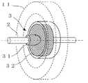
11 環状回転体
2 シャフト
21 回転ローラーのシャフト
22 プーリーのシャフト
3 固定部
31 シャフトに固定される固定軸
32 所定の傾斜を有する傾斜円盤
4 回転駆動体
41 回転体の外周で駆動する回転駆動体
42 プーリーを用いて駆動する回転駆動体
5 駆動用プーリー
6 コンベア部
7 弾性体(合成樹脂など)
71 環状回転体に固着される弾性体
72 回転駆動体に固着される弾性体
8 摺接機構
81 固定部と環状回転体とを摺接可能とするベアリング構造
82 シャフトと回転駆動体とを摺接可能とするベアリング構造
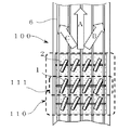
100 搬送装置の仕分部
110 回転体ユニット
111 軸ユニット
200 搬送される物品
A,B,C 搬送方向
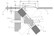
Dコンベアと回転体の位置関係を示す寸法
D1 コンベア部の厚さ
D2 環状回転体がコンベア表面から突出する最大量
D3 環状回転体がコンベア表面から埋没する最大量
D4 回転駆動体とコンベア底面との余裕間隙
E回転力を生じさせるための外力
E1、E2 従来構造での円盤の外周部を押圧する力
E3、E4 従来構造での回転体を引っ張る力
E5、E6 従来構造での円盤の表面を押圧する力
E11 固定部を押圧する力
E12 回転駆動体を押圧する力
E21 前記E12の力によって回転駆動体が受ける反力
E22 前記E11の力によって駆動回転体が受ける反力
E23 回転駆動体の回転力が加わった時の、図の手前方向を向くベクトルを示す力
E33 回転駆動体により圧せられる力による垂直方向の分力
E34 回転駆動体の回転による回転方向の分力
L コンベア間の間隙長さ
L1 回転体の最大外形部がコンベア表面から突出する領域
R 回転力
R1 回転駆動体により駆動される環状回転体の回転力
R2 回転駆動体の回転力
r 環状回転体部の径
r1 環状回転体11の外径
r2 環状回転体11の内径
t 環状回転体11の厚さ
θ 固定部傾斜盤および環状回転体の、シャフトに対する傾斜角度
Claims (4)
- 第1シャフト(2)と、前記第1シャフトの周囲を回転する回転体であって、前記第1シャフトの軸に対してある角度傾いた回転軸を有する第1回転体(11)と、前記第1シャフトと前記第1回転体との間に位置し、前記第1回転体を回転可能に支持する第1支持体(3)と、前記第1回転体を回転駆動させるための第1駆動体(4)と、を備えた分岐装置であって、
前記第1支持体は、前記第1シャフトと前記第1回転体との間に位置する円盤であって前記第1回転体と同心円の第1傾斜円盤(32)と、前記第1傾斜円盤の外周に位置し、前記第1傾斜円盤に対して前記第1回転体を回転可能に支持する第1回転機構(81)とを備え、
前記第1回転体の回転軸に平行な方向の前記第1回転体の厚みが、前記第1回転体の回転軸に平行な方向の前記第1傾斜円盤の厚みより厚いことを特徴とする分岐装置。 - 前記第1回転体(11)と前記第1駆動体(4)とが互いに接する部分において押圧力がかかり、前記第1駆動体(4)の回転が前記押圧力及び摩擦により前記第1回転体(11)に伝搬することを特徴とする請求項1に記載の分岐装置。
- 前記第1回転体(11)と前記第1駆動体(4)とが互いに接する部分における前記押圧力及び慣性モーメントを利用したことを特徴とする請求項2に記載の分岐装置。
- 前記第1支持体(3)の傾斜方向が変化することによって前記第1回転体(11)の最大外周部の高さ位置が変化することを特徴とする請求項1ないし3のいずれかに記載の分岐装置。
Priority Applications (1)
| Application Number | Priority Date | Filing Date | Title |
|---|---|---|---|
| JP2019193078A JP6823137B2 (ja) | 2019-10-23 | 2019-10-23 | 仕分装置 |
Applications Claiming Priority (1)
| Application Number | Priority Date | Filing Date | Title |
|---|---|---|---|
| JP2019193078A JP6823137B2 (ja) | 2019-10-23 | 2019-10-23 | 仕分装置 |
Related Parent Applications (1)
| Application Number | Title | Priority Date | Filing Date |
|---|---|---|---|
| JP2015073169A Division JP6683970B2 (ja) | 2015-03-31 | 2015-03-31 | 仕分装置 |
Publications (3)
| Publication Number | Publication Date |
|---|---|
| JP2020029370A JP2020029370A (ja) | 2020-02-27 |
| JP2020029370A5 JP2020029370A5 (ja) | 2020-05-28 |
| JP6823137B2 true JP6823137B2 (ja) | 2021-01-27 |
Family
ID=69623740
Family Applications (1)
| Application Number | Title | Priority Date | Filing Date |
|---|---|---|---|
| JP2019193078A Active JP6823137B2 (ja) | 2019-10-23 | 2019-10-23 | 仕分装置 |
Country Status (1)
| Country | Link |
|---|---|
| JP (1) | JP6823137B2 (ja) |
Family Cites Families (5)
| Publication number | Priority date | Publication date | Assignee | Title |
|---|---|---|---|---|
| JPS5322331Y2 (ja) * | 1972-02-21 | 1978-06-10 | ||
| FR2663311B1 (fr) * | 1990-06-14 | 1992-10-09 | Bourges Inst Univers Technolog | Trieur pour convoyeur. |
| JPH085141Y2 (ja) * | 1991-03-27 | 1996-02-14 | トーヨーカネツ株式会社 | 仕分装置 |
| JPH0526921U (ja) * | 1991-09-20 | 1993-04-06 | トーヨーカネツ株式会社 | 仕分装置 |
| JPH06219522A (ja) * | 1993-01-22 | 1994-08-09 | Tomio Imamura | ローラコンベア |
-
2019
- 2019-10-23 JP JP2019193078A patent/JP6823137B2/ja active Active
Also Published As
| Publication number | Publication date |
|---|---|
| JP2020029370A (ja) | 2020-02-27 |
Similar Documents
| Publication | Publication Date | Title |
|---|---|---|
| KR20170036303A (ko) | 컨베이어의 방향전환장치 | |
| KR20180014679A (ko) | 방향전환장치를 갖는 컨베이어 | |
| JP6683970B2 (ja) | 仕分装置 | |
| JP6823137B2 (ja) | 仕分装置 | |
| KR200410926Y1 (ko) | 방향전환용 롤러가 장착된 롤러형 콘베이어 | |
| CN111689188A (zh) | 一种换向输送装置及换向控制方法 | |
| US6935486B2 (en) | Bushing system for live roller conveyor | |
| JP3828108B2 (ja) | コンベア装置 | |
| JPH0526921U (ja) | 仕分装置 | |
| JP6850122B2 (ja) | 搬送方向変換装置 | |
| JP6987431B2 (ja) | ホイール式方向変換装置 | |
| JP6771864B2 (ja) | 仕分装置 | |
| JP6902593B2 (ja) | 仕分装置 | |
| JP6822754B2 (ja) | 仕分装置 | |
| JP3290399B2 (ja) | コンベア | |
| WO2019208000A1 (ja) | 搬送仕分け装置 | |
| JP3246309U (ja) | 搬送装置 | |
| JPH11246040A (ja) | 搬送物の仕分け装置 | |
| JP6577230B2 (ja) | 仕分装置 | |
| CN215478304U (zh) | 传送装置 | |
| KR102321327B1 (ko) | 물류용 소터 | |
| JP6577219B2 (ja) | 仕分装置 | |
| JPS6233167B2 (ja) | ||
| JP6426807B2 (ja) | 停止装置 | |
| JP6880449B2 (ja) | パレット搬送装置 |
Legal Events
| Date | Code | Title | Description |
|---|---|---|---|
| A621 | Written request for application examination |
Free format text: JAPANESE INTERMEDIATE CODE: A621 Effective date: 20191122 |
|
| A521 | Request for written amendment filed |
Free format text: JAPANESE INTERMEDIATE CODE: A523 Effective date: 20200117 |
|
| A521 | Request for written amendment filed |
Free format text: JAPANESE INTERMEDIATE CODE: A523 Effective date: 20200406 |
|
| A521 | Request for written amendment filed |
Free format text: JAPANESE INTERMEDIATE CODE: A523 Effective date: 20200408 |
|
| A711 | Notification of change in applicant |
Free format text: JAPANESE INTERMEDIATE CODE: A712 Effective date: 20200408 |
|
| A521 | Request for written amendment filed |
Free format text: JAPANESE INTERMEDIATE CODE: A523 Effective date: 20200410 |
|
| A977 | Report on retrieval |
Free format text: JAPANESE INTERMEDIATE CODE: A971007 Effective date: 20201012 |
|
| TRDD | Decision of grant or rejection written | ||
| A01 | Written decision to grant a patent or to grant a registration (utility model) |
Free format text: JAPANESE INTERMEDIATE CODE: A01 Effective date: 20201208 |
|
| A61 | First payment of annual fees (during grant procedure) |
Free format text: JAPANESE INTERMEDIATE CODE: A61 Effective date: 20210107 |
|
| R150 | Certificate of patent or registration of utility model |
Ref document number: 6823137 Country of ref document: JP Free format text: JAPANESE INTERMEDIATE CODE: R150 |
|
| R250 | Receipt of annual fees |
Free format text: JAPANESE INTERMEDIATE CODE: R250 |