JP6773416B2 - Artificial valve for mitral valve replacement - Google Patents
Artificial valve for mitral valve replacement Download PDFInfo
- Publication number
- JP6773416B2 JP6773416B2 JP2015556233A JP2015556233A JP6773416B2 JP 6773416 B2 JP6773416 B2 JP 6773416B2 JP 2015556233 A JP2015556233 A JP 2015556233A JP 2015556233 A JP2015556233 A JP 2015556233A JP 6773416 B2 JP6773416 B2 JP 6773416B2
- Authority
- JP
- Japan
- Prior art keywords
- atrial
- valve
- fixation
- ventricular
- frame
- Prior art date
- Legal status (The legal status is an assumption and is not a legal conclusion. Google has not performed a legal analysis and makes no representation as to the accuracy of the status listed.)
- Active
Links
Images


Classifications
-
- A—HUMAN NECESSITIES
- A61—MEDICAL OR VETERINARY SCIENCE; HYGIENE
- A61F—FILTERS IMPLANTABLE INTO BLOOD VESSELS; PROSTHESES; DEVICES PROVIDING PATENCY TO, OR PREVENTING COLLAPSING OF, TUBULAR STRUCTURES OF THE BODY, e.g. STENTS; ORTHOPAEDIC, NURSING OR CONTRACEPTIVE DEVICES; FOMENTATION; TREATMENT OR PROTECTION OF EYES OR EARS; BANDAGES, DRESSINGS OR ABSORBENT PADS; FIRST-AID KITS
- A61F2/00—Filters implantable into blood vessels; Prostheses, i.e. artificial substitutes or replacements for parts of the body; Appliances for connecting them with the body; Devices providing patency to, or preventing collapsing of, tubular structures of the body, e.g. stents
- A61F2/02—Prostheses implantable into the body
- A61F2/24—Heart valves ; Vascular valves, e.g. venous valves; Heart implants, e.g. passive devices for improving the function of the native valve or the heart muscle; Transmyocardial revascularisation [TMR] devices; Valves implantable in the body
- A61F2/2412—Heart valves ; Vascular valves, e.g. venous valves; Heart implants, e.g. passive devices for improving the function of the native valve or the heart muscle; Transmyocardial revascularisation [TMR] devices; Valves implantable in the body with soft flexible valve members, e.g. tissue valves shaped like natural valves
- A61F2/2418—Scaffolds therefor, e.g. support stents
-
- A—HUMAN NECESSITIES
- A61—MEDICAL OR VETERINARY SCIENCE; HYGIENE
- A61F—FILTERS IMPLANTABLE INTO BLOOD VESSELS; PROSTHESES; DEVICES PROVIDING PATENCY TO, OR PREVENTING COLLAPSING OF, TUBULAR STRUCTURES OF THE BODY, e.g. STENTS; ORTHOPAEDIC, NURSING OR CONTRACEPTIVE DEVICES; FOMENTATION; TREATMENT OR PROTECTION OF EYES OR EARS; BANDAGES, DRESSINGS OR ABSORBENT PADS; FIRST-AID KITS
- A61F2/00—Filters implantable into blood vessels; Prostheses, i.e. artificial substitutes or replacements for parts of the body; Appliances for connecting them with the body; Devices providing patency to, or preventing collapsing of, tubular structures of the body, e.g. stents
- A61F2/02—Prostheses implantable into the body
- A61F2/24—Heart valves ; Vascular valves, e.g. venous valves; Heart implants, e.g. passive devices for improving the function of the native valve or the heart muscle; Transmyocardial revascularisation [TMR] devices; Valves implantable in the body
- A61F2/2409—Support rings therefor, e.g. for connecting valves to tissue
-
- A—HUMAN NECESSITIES
- A61—MEDICAL OR VETERINARY SCIENCE; HYGIENE
- A61F—FILTERS IMPLANTABLE INTO BLOOD VESSELS; PROSTHESES; DEVICES PROVIDING PATENCY TO, OR PREVENTING COLLAPSING OF, TUBULAR STRUCTURES OF THE BODY, e.g. STENTS; ORTHOPAEDIC, NURSING OR CONTRACEPTIVE DEVICES; FOMENTATION; TREATMENT OR PROTECTION OF EYES OR EARS; BANDAGES, DRESSINGS OR ABSORBENT PADS; FIRST-AID KITS
- A61F2/00—Filters implantable into blood vessels; Prostheses, i.e. artificial substitutes or replacements for parts of the body; Appliances for connecting them with the body; Devices providing patency to, or preventing collapsing of, tubular structures of the body, e.g. stents
- A61F2/02—Prostheses implantable into the body
- A61F2/24—Heart valves ; Vascular valves, e.g. venous valves; Heart implants, e.g. passive devices for improving the function of the native valve or the heart muscle; Transmyocardial revascularisation [TMR] devices; Valves implantable in the body
- A61F2/2412—Heart valves ; Vascular valves, e.g. venous valves; Heart implants, e.g. passive devices for improving the function of the native valve or the heart muscle; Transmyocardial revascularisation [TMR] devices; Valves implantable in the body with soft flexible valve members, e.g. tissue valves shaped like natural valves
-
- A—HUMAN NECESSITIES
- A61—MEDICAL OR VETERINARY SCIENCE; HYGIENE
- A61F—FILTERS IMPLANTABLE INTO BLOOD VESSELS; PROSTHESES; DEVICES PROVIDING PATENCY TO, OR PREVENTING COLLAPSING OF, TUBULAR STRUCTURES OF THE BODY, e.g. STENTS; ORTHOPAEDIC, NURSING OR CONTRACEPTIVE DEVICES; FOMENTATION; TREATMENT OR PROTECTION OF EYES OR EARS; BANDAGES, DRESSINGS OR ABSORBENT PADS; FIRST-AID KITS
- A61F2/00—Filters implantable into blood vessels; Prostheses, i.e. artificial substitutes or replacements for parts of the body; Appliances for connecting them with the body; Devices providing patency to, or preventing collapsing of, tubular structures of the body, e.g. stents
- A61F2/02—Prostheses implantable into the body
- A61F2/24—Heart valves ; Vascular valves, e.g. venous valves; Heart implants, e.g. passive devices for improving the function of the native valve or the heart muscle; Transmyocardial revascularisation [TMR] devices; Valves implantable in the body
- A61F2/2427—Devices for manipulating or deploying heart valves during implantation
- A61F2/2436—Deployment by retracting a sheath
-
- A—HUMAN NECESSITIES
- A61—MEDICAL OR VETERINARY SCIENCE; HYGIENE
- A61F—FILTERS IMPLANTABLE INTO BLOOD VESSELS; PROSTHESES; DEVICES PROVIDING PATENCY TO, OR PREVENTING COLLAPSING OF, TUBULAR STRUCTURES OF THE BODY, e.g. STENTS; ORTHOPAEDIC, NURSING OR CONTRACEPTIVE DEVICES; FOMENTATION; TREATMENT OR PROTECTION OF EYES OR EARS; BANDAGES, DRESSINGS OR ABSORBENT PADS; FIRST-AID KITS
- A61F2/00—Filters implantable into blood vessels; Prostheses, i.e. artificial substitutes or replacements for parts of the body; Appliances for connecting them with the body; Devices providing patency to, or preventing collapsing of, tubular structures of the body, e.g. stents
- A61F2/02—Prostheses implantable into the body
- A61F2/24—Heart valves ; Vascular valves, e.g. venous valves; Heart implants, e.g. passive devices for improving the function of the native valve or the heart muscle; Transmyocardial revascularisation [TMR] devices; Valves implantable in the body
- A61F2/2442—Annuloplasty rings or inserts for correcting the valve shape; Implants for improving the function of a native heart valve
- A61F2/2466—Delivery devices therefor
-
- A—HUMAN NECESSITIES
- A61—MEDICAL OR VETERINARY SCIENCE; HYGIENE
- A61B—DIAGNOSIS; SURGERY; IDENTIFICATION
- A61B6/00—Apparatus for radiation diagnosis, e.g. combined with radiation therapy equipment
- A61B6/44—Constructional features of apparatus for radiation diagnosis
- A61B6/4429—Constructional features of apparatus for radiation diagnosis related to the mounting of source units and detector units
- A61B6/4435—Constructional features of apparatus for radiation diagnosis related to the mounting of source units and detector units the source unit and the detector unit being coupled by a rigid structure
- A61B6/4441—Constructional features of apparatus for radiation diagnosis related to the mounting of source units and detector units the source unit and the detector unit being coupled by a rigid structure the rigid structure being a C-arm or U-arm
-
- A—HUMAN NECESSITIES
- A61—MEDICAL OR VETERINARY SCIENCE; HYGIENE
- A61B—DIAGNOSIS; SURGERY; IDENTIFICATION
- A61B8/00—Diagnosis using ultrasonic, sonic or infrasonic waves
- A61B8/12—Diagnosis using ultrasonic, sonic or infrasonic waves in body cavities or body tracts, e.g. by using catheters
-
- A—HUMAN NECESSITIES
- A61—MEDICAL OR VETERINARY SCIENCE; HYGIENE
- A61F—FILTERS IMPLANTABLE INTO BLOOD VESSELS; PROSTHESES; DEVICES PROVIDING PATENCY TO, OR PREVENTING COLLAPSING OF, TUBULAR STRUCTURES OF THE BODY, e.g. STENTS; ORTHOPAEDIC, NURSING OR CONTRACEPTIVE DEVICES; FOMENTATION; TREATMENT OR PROTECTION OF EYES OR EARS; BANDAGES, DRESSINGS OR ABSORBENT PADS; FIRST-AID KITS
- A61F2210/00—Particular material properties of prostheses classified in groups A61F2/00 - A61F2/26 or A61F2/82 or A61F9/00 or A61F11/00 or subgroups thereof
- A61F2210/0014—Particular material properties of prostheses classified in groups A61F2/00 - A61F2/26 or A61F2/82 or A61F9/00 or A61F11/00 or subgroups thereof using shape memory or superelastic materials, e.g. nitinol
-
- A—HUMAN NECESSITIES
- A61—MEDICAL OR VETERINARY SCIENCE; HYGIENE
- A61F—FILTERS IMPLANTABLE INTO BLOOD VESSELS; PROSTHESES; DEVICES PROVIDING PATENCY TO, OR PREVENTING COLLAPSING OF, TUBULAR STRUCTURES OF THE BODY, e.g. STENTS; ORTHOPAEDIC, NURSING OR CONTRACEPTIVE DEVICES; FOMENTATION; TREATMENT OR PROTECTION OF EYES OR EARS; BANDAGES, DRESSINGS OR ABSORBENT PADS; FIRST-AID KITS
- A61F2220/00—Fixations or connections for prostheses classified in groups A61F2/00 - A61F2/26 or A61F2/82 or A61F9/00 or A61F11/00 or subgroups thereof
- A61F2220/0008—Fixation appliances for connecting prostheses to the body
- A61F2220/0016—Fixation appliances for connecting prostheses to the body with sharp anchoring protrusions, e.g. barbs, pins, spikes
-
- A—HUMAN NECESSITIES
- A61—MEDICAL OR VETERINARY SCIENCE; HYGIENE
- A61F—FILTERS IMPLANTABLE INTO BLOOD VESSELS; PROSTHESES; DEVICES PROVIDING PATENCY TO, OR PREVENTING COLLAPSING OF, TUBULAR STRUCTURES OF THE BODY, e.g. STENTS; ORTHOPAEDIC, NURSING OR CONTRACEPTIVE DEVICES; FOMENTATION; TREATMENT OR PROTECTION OF EYES OR EARS; BANDAGES, DRESSINGS OR ABSORBENT PADS; FIRST-AID KITS
- A61F2220/00—Fixations or connections for prostheses classified in groups A61F2/00 - A61F2/26 or A61F2/82 or A61F9/00 or A61F11/00 or subgroups thereof
- A61F2220/0025—Connections or couplings between prosthetic parts, e.g. between modular parts; Connecting elements
- A61F2220/0075—Connections or couplings between prosthetic parts, e.g. between modular parts; Connecting elements sutured, ligatured or stitched, retained or tied with a rope, string, thread, wire or cable
-
- A—HUMAN NECESSITIES
- A61—MEDICAL OR VETERINARY SCIENCE; HYGIENE
- A61F—FILTERS IMPLANTABLE INTO BLOOD VESSELS; PROSTHESES; DEVICES PROVIDING PATENCY TO, OR PREVENTING COLLAPSING OF, TUBULAR STRUCTURES OF THE BODY, e.g. STENTS; ORTHOPAEDIC, NURSING OR CONTRACEPTIVE DEVICES; FOMENTATION; TREATMENT OR PROTECTION OF EYES OR EARS; BANDAGES, DRESSINGS OR ABSORBENT PADS; FIRST-AID KITS
- A61F2230/00—Geometry of prostheses classified in groups A61F2/00 - A61F2/26 or A61F2/82 or A61F9/00 or A61F11/00 or subgroups thereof
- A61F2230/0002—Two-dimensional shapes, e.g. cross-sections
- A61F2230/0028—Shapes in the form of latin or greek characters
- A61F2230/005—Rosette-shaped, e.g. star-shaped
-
- A—HUMAN NECESSITIES
- A61—MEDICAL OR VETERINARY SCIENCE; HYGIENE
- A61F—FILTERS IMPLANTABLE INTO BLOOD VESSELS; PROSTHESES; DEVICES PROVIDING PATENCY TO, OR PREVENTING COLLAPSING OF, TUBULAR STRUCTURES OF THE BODY, e.g. STENTS; ORTHOPAEDIC, NURSING OR CONTRACEPTIVE DEVICES; FOMENTATION; TREATMENT OR PROTECTION OF EYES OR EARS; BANDAGES, DRESSINGS OR ABSORBENT PADS; FIRST-AID KITS
- A61F2230/00—Geometry of prostheses classified in groups A61F2/00 - A61F2/26 or A61F2/82 or A61F9/00 or A61F11/00 or subgroups thereof
- A61F2230/0002—Two-dimensional shapes, e.g. cross-sections
- A61F2230/0028—Shapes in the form of latin or greek characters
- A61F2230/0054—V-shaped
-
- A—HUMAN NECESSITIES
- A61—MEDICAL OR VETERINARY SCIENCE; HYGIENE
- A61F—FILTERS IMPLANTABLE INTO BLOOD VESSELS; PROSTHESES; DEVICES PROVIDING PATENCY TO, OR PREVENTING COLLAPSING OF, TUBULAR STRUCTURES OF THE BODY, e.g. STENTS; ORTHOPAEDIC, NURSING OR CONTRACEPTIVE DEVICES; FOMENTATION; TREATMENT OR PROTECTION OF EYES OR EARS; BANDAGES, DRESSINGS OR ABSORBENT PADS; FIRST-AID KITS
- A61F2230/00—Geometry of prostheses classified in groups A61F2/00 - A61F2/26 or A61F2/82 or A61F9/00 or A61F11/00 or subgroups thereof
- A61F2230/0063—Three-dimensional shapes
- A61F2230/0073—Quadric-shaped
- A61F2230/0078—Quadric-shaped hyperboloidal
-
- A—HUMAN NECESSITIES
- A61—MEDICAL OR VETERINARY SCIENCE; HYGIENE
- A61F—FILTERS IMPLANTABLE INTO BLOOD VESSELS; PROSTHESES; DEVICES PROVIDING PATENCY TO, OR PREVENTING COLLAPSING OF, TUBULAR STRUCTURES OF THE BODY, e.g. STENTS; ORTHOPAEDIC, NURSING OR CONTRACEPTIVE DEVICES; FOMENTATION; TREATMENT OR PROTECTION OF EYES OR EARS; BANDAGES, DRESSINGS OR ABSORBENT PADS; FIRST-AID KITS
- A61F2250/00—Special features of prostheses classified in groups A61F2/00 - A61F2/26 or A61F2/82 or A61F9/00 or A61F11/00 or subgroups thereof
- A61F2250/0014—Special features of prostheses classified in groups A61F2/00 - A61F2/26 or A61F2/82 or A61F9/00 or A61F11/00 or subgroups thereof having different values of a given property or geometrical feature, e.g. mechanical property or material property, at different locations within the same prosthesis
- A61F2250/0018—Special features of prostheses classified in groups A61F2/00 - A61F2/26 or A61F2/82 or A61F9/00 or A61F11/00 or subgroups thereof having different values of a given property or geometrical feature, e.g. mechanical property or material property, at different locations within the same prosthesis differing in elasticity, stiffness or compressibility
-
- A—HUMAN NECESSITIES
- A61—MEDICAL OR VETERINARY SCIENCE; HYGIENE
- A61F—FILTERS IMPLANTABLE INTO BLOOD VESSELS; PROSTHESES; DEVICES PROVIDING PATENCY TO, OR PREVENTING COLLAPSING OF, TUBULAR STRUCTURES OF THE BODY, e.g. STENTS; ORTHOPAEDIC, NURSING OR CONTRACEPTIVE DEVICES; FOMENTATION; TREATMENT OR PROTECTION OF EYES OR EARS; BANDAGES, DRESSINGS OR ABSORBENT PADS; FIRST-AID KITS
- A61F2250/00—Special features of prostheses classified in groups A61F2/00 - A61F2/26 or A61F2/82 or A61F9/00 or A61F11/00 or subgroups thereof
- A61F2250/0014—Special features of prostheses classified in groups A61F2/00 - A61F2/26 or A61F2/82 or A61F9/00 or A61F11/00 or subgroups thereof having different values of a given property or geometrical feature, e.g. mechanical property or material property, at different locations within the same prosthesis
- A61F2250/0029—Special features of prostheses classified in groups A61F2/00 - A61F2/26 or A61F2/82 or A61F9/00 or A61F11/00 or subgroups thereof having different values of a given property or geometrical feature, e.g. mechanical property or material property, at different locations within the same prosthesis differing in bending or flexure capacity
-
- A—HUMAN NECESSITIES
- A61—MEDICAL OR VETERINARY SCIENCE; HYGIENE
- A61F—FILTERS IMPLANTABLE INTO BLOOD VESSELS; PROSTHESES; DEVICES PROVIDING PATENCY TO, OR PREVENTING COLLAPSING OF, TUBULAR STRUCTURES OF THE BODY, e.g. STENTS; ORTHOPAEDIC, NURSING OR CONTRACEPTIVE DEVICES; FOMENTATION; TREATMENT OR PROTECTION OF EYES OR EARS; BANDAGES, DRESSINGS OR ABSORBENT PADS; FIRST-AID KITS
- A61F2250/00—Special features of prostheses classified in groups A61F2/00 - A61F2/26 or A61F2/82 or A61F9/00 or A61F11/00 or subgroups thereof
- A61F2250/0058—Additional features; Implant or prostheses properties not otherwise provided for
- A61F2250/0069—Sealing means
Description
[関連出願の相互参照]
本願は、2013年2月4日に出願された米国特許出願第61/760,577号および2013年12月11日に出願された米国特許出願第61/914,648号の利益を主張するものである。これらの特許出願は、参照によりその全体が本明細書に組み込まれる。
[Cross-reference of related applications]
This application claims the interests of U.S. Patent Application Nos. 61 / 760,577 filed on February 4, 2013 and U.S. Patent Application No. 61 / 914,648 filed on December 11, 2013. Is. These patent applications are incorporated herein by reference in their entirety.
本開示は、一般的には天然心臓弁を修復および/または置換するためのプロテーゼデバイスに関し、詳細には欠陥を有する僧帽弁を置換するための人工弁と、ヒトの心臓内にその人工弁を送達するおよび植え込むための方法およびデバイスとに関する。 The present disclosure relates generally to prosthesis devices for repairing and / or replacing natural heart valves, in particular prosthetic valves for replacing defective mitral valves and their prosthetic valves in the human heart. With respect to methods and devices for delivering and implanting.
人工弁は、心臓弁障害を治療するために長年にわたり使用されている。天然心臓弁(すなわち大動脈弁、肺動脈弁、三尖弁、および僧帽弁)は、心血管系における順方向への十分な血液供給流を確保する点において極めて重要な機能を果たす。これらの心臓弁は、先天性奇形、炎症過程、感染状態、または感染症によって効力が減じられ得る。弁へのかかる損傷は、結果として深刻な心血管の損傷または死をもたらすおそれがある。長年にわたり、かかる障害の最も確実な治療は、開心術時の弁の外科的修復または置換であった。しかし、かかる手術は、侵襲性が高く、多数の合併症を招く傾向がある。したがって、心臓弁に欠陥を有する中高年の虚弱患者は、未治療のままとなることがしばしばある。さらに近年では、開心術よりもはるかに低侵襲である様式で可撓性カテーテルを使用して人工心臓弁を導入し植え込むための経血管技術が展開されている。 Artificial valves have been used for many years to treat heart valve disorders. Natural heart valves (ie, aortic valves, pulmonary valves, tricuspid valves, and mitral valves) play a vital role in ensuring adequate forward blood flow in the cardiovascular system. These heart valves can be diminished by congenital malformations, inflammatory processes, infectious conditions, or infections. Such damage to the valve can result in serious cardiovascular damage or death. For many years, the most reliable treatment for such disorders has been surgical repair or replacement of the valve during open heart surgery. However, such surgery is highly invasive and tends to lead to numerous complications. Therefore, middle-aged and frail patients with heart valve defects often remain untreated. More recently, transvascular techniques have been developed to introduce and implant artificial heart valves using flexible catheters in a manner that is far less invasive than open heart surgery.
この技術では、人工弁は、可撓性カテーテルの端部部分上に圧着状態で取り付けられ、弁が植え込み部位に到達するまで患者の血管を通して前進される。次いで、カテーテル先端部の弁は、弁が取り付けられたバルーンを膨張させることによってなど、欠陥を有する天然弁の部位でその機能サイズまで拡張される。 In this technique, the prosthetic valve is crimp-mounted onto the end of the flexible catheter and advanced through the patient's blood vessel until the valve reaches the implantation site. The valve at the tip of the catheter is then extended to its functional size at the site of the defective natural valve, such as by inflating a balloon to which the valve is attached.
人工大動脈弁を植え込むための別の既知の技術は、経心尖アプローチであり、小切開部が患者の胸壁に形成され、カテーテルが心臓の心尖(すなわち下方先端部)を通して前進される。経心尖技術は、特許文献1に開示されており、これは参照により本明細書に組み込まれる。経血管アプローチと同様に、経心尖アプローチは、挿入器を介して大動脈弁輪にバルーン拡張式人工心臓弁を送達するための操縦機構を有するバルーンカテーテルを含むことが可能である。バルーンカテーテルは、大動脈弁輪内で適切な配向に人工心臓弁を位置決めするのを容易にするために、遠位バルーンの直近位にたわみセグメントを備えることが可能である。
Another known technique for implanting an artificial aortic valve is the transapical approach, in which a small incision is made in the patient's chest wall and the catheter is advanced through the apex of the heart (ie, the inferior tip). The transapical technique is disclosed in
上記のおよび他の技術は、開心術および心肺バイパスがもたらす結果を回避するために、大動脈弁疾患を有する手術危険度の高い患者のための多数のオプションを提供している。大動脈弁用のデバイスおよび手技が十分に展開されている一方で、かかるカテーテルベースの手技は、大動脈弁と僧帽弁との間の顕著な相違により、僧帽弁に対して必ずしも適用可能ではない。僧帽弁は、複雑な弁下装置を、すなわち大動脈弁には存在しない腱索を有する。 The above and other techniques offer a number of options for patients at high risk of surgery with aortic valve disease to avoid the consequences of open heart surgery and cardiopulmonary bypass. While devices and procedures for the aortic valve are well deployed, such catheter-based procedures are not always applicable to the mitral valve due to the significant differences between the aortic and mitral valves. .. The mitral valve has a complex subvalvular device, a chordae tendineae that is not present in the aortic valve.
外科的僧帽弁修復技術(例えば僧帽弁形成術)は、その高い成功率と修復後に認められる臨床的改善とにより人気が高まっている。既存の僧帽弁修復技術に加えて、僧帽弁修復をより低侵襲性の手技にすることを目的とした複数の新たな技術が存在する。これらの技術は、アルフィエーリ縫合術の反復から、僧帽弁の解剖学的構造の冠状静脈洞ベース変更、弁下縫縮術、または随伴的に僧帽弁逆流を補正する心室リモデリングデバイスにまで及ぶ。 Surgical mitral valve repair techniques (eg, mitral valve repair) are becoming more popular due to their high success rate and the clinical improvement seen after repair. In addition to existing mitral valve repair techniques, there are several new techniques aimed at making mitral valve repair a less invasive procedure. These techniques range from repeated Alfieri sutures to coronary sinus-based alterations of the mitral valve anatomy, subvalvular plication, or concomitant ventricular remodeling devices to correct mitral regurgitation. It extends to.
しかし、僧帽弁置換のためには、利用可能な低侵襲オプションはごくわずかである。米国では毎年約25,000回の僧帽弁置換(MVR)が行われている。しかし、推定によれば、治療ガイドラインを満たす300,000人を超える患者が年齢および/または共存症に基づき治療を拒否される。したがって、僧帽弁置換のための低侵襲技術の需要が存在する。 However, there are very few minimally invasive options available for mitral valve replacement. About 25,000 mitral valve replacements (MVRs) are performed annually in the United States. However, it is estimated that more than 300,000 patients who meet treatment guidelines will be denied treatment based on age and / or comorbidities. Therefore, there is a demand for minimally invasive techniques for mitral valve replacement.
本明細書では、人工僧帽弁、その構成要素、ならびにこれらを植え込むための方法およびデバイスが説明される。 As used herein, artificial mitral valves, their components, and methods and devices for implanting them are described.
心臓の天然僧帽弁領域に植え込むように構成され、径方向に圧縮された状態へと径方向に圧縮可能であり圧縮された状態から径方向に拡張された状態へと自動拡張可能である本体を備える、プロテーゼ装置が説明される。また、プロテーゼ装置は、本体に結合され本体の外部に配設される少なくとも1つの心室固定部を備え、それにより、本体が圧縮状態に圧縮された場合に、心室固定部と本体の外方表面との間の弁尖受け空間がそれらの間に天然弁尖を受けるように増大する。本体が、本体または心室固定部に対するいかなる実質的な外部内方力もない状態で拡張状態へと自動拡張すると、この空間は、本体と心室固定部との間に弁尖を捕獲するように縮小する。 A body that is configured to be implanted in the natural mitral valve region of the heart and is radially compressible to a radially compressed state and automatically expandable from a compressed state to a radially expanded state. A prosthesis device comprising. Also, the prosthesis device comprises at least one ventricular fixation portion coupled to the main body and disposed outside the main body, whereby the ventricular fixation portion and the outer surface of the main body when the main body is compressed into a compressed state. The valve leaflet receiving space between them increases to receive the natural valve leaflets between them. When the body automatically expands into an expanded state without any substantial external internal force on the body or ventricular fixation, this space shrinks to capture the valve leaflets between the body and the ventricular fixation. ..
いくつかの実施形態では、心臓の天然僧帽弁領域に植え込むためのプロテーゼ装置は、本体を有するフレームと、本体に結合され本体の外部に配設された少なくとも1つの心室固定部とを備える。また、プロテーゼ装置は、本体を通過する血流のための一方向弁を形成する本体により支持される複数の弁尖を備える。本体は、本体内への送達のために径方向に圧縮された状態に径方向に圧縮可能であり、圧縮された状態から径方向に拡張された状態へと自動拡張可能である。心室固定部は、本体に固定的に固定されたベースと、ベースの対向側の自由端部分と、心室固定部と本体との間に天然弁の弁尖を受けるための弁尖受け空間を画成する中間部分とを備える。心室固定部に対するいかなる径方向内方力もない状態で、圧縮された状態から径方向に拡張された状態へと本体が拡張することにより、弁尖受け空間は縮小する。 In some embodiments, the prosthesis device for implantation in the natural mitral valve region of the heart comprises a frame having a body and at least one ventricular fixation portion coupled to the body and disposed outside the body. The prosthesis device also comprises a plurality of leaflets supported by the body forming a one-way valve for blood flow through the body. The body can be radially compressed in a radially compressed state for delivery into the body, and can be automatically expanded from a compressed state to a radially expanded state. The ventricular fixation part defines a valve leaflet receiving space for receiving the valve leaflet of a natural valve between the base fixedly fixed to the main body, the free end portion on the opposite side of the base, and the ventricle fixing part and the main body. It has an intermediate part to be formed. The valve apex receiving space shrinks as the body expands from a compressed state to a radially expanded state without any radial inward force on the ventricular fixation.
他の実施形態では、天然僧帽弁領域に植え込むためのプロテーゼ装置は、本体と、少なくとも1つの心室固定部と、少なくとも1つの心房固定部とを備える。本体は、天然僧帽弁内に配置されるように構成され、心臓内への送達のために圧縮状態に圧縮可能であり、圧縮状態から拡張状態へと自動拡張可能である。少なくとも1つの心室固定部が、本体に結合され、本体の外部に配設され、それにより拡張状態では、弁尖受け空間は、心室固定部と本体の外方表面との間に存在して天然弁尖の自由端部部分を受ける。心室固定部は、受けられた天然弁尖の背後に延在し、天然僧帽弁輪の心室表面、受けられた天然弁尖の弁輪連結部分、または天然弁輪の心室表面および受けられた天然弁尖の弁輪連結部分の両方に接触するように構成された係合部分を備える。少なくとも1つの心房封止部材が、本体に結合され本体の外部に配設され、プロテーゼ装置の保持および/または弁傍漏出の防止のために心室固定部の係合部分から対向側の位置にて、天然僧帽弁輪の心房部分、受けられた天然弁尖の弁輪連結部分、または天然弁輪の心房表面および受けられた天然弁尖の弁輪連結部分の両方に接触するように構成される。 In another embodiment, the prosthesis device for implantation in the natural mitral valve region comprises a body, at least one ventricular fixation, and at least one atrial fixation. The body is configured to be placed within the natural mitral valve, is compressible into a compressed state for delivery into the heart, and is auto-expandable from a compressed state to an expanded state. At least one ventricular fixation is coupled to the body and disposed outside the body, whereby in the expanded state, the valve leaflet receiving space is naturally present between the ventricular fixation and the outer surface of the body. Receives the free end of the valve leaflet. The ventricular fixation extends behind the received natural valve leaflet and is the ventricular surface of the natural mitral valve annulus, the annulus junction of the received natural valve leaflet, or the ventricular surface of the natural valve annulus and received. It comprises an engaging portion configured to contact both of the annulus connecting portions of the natural valve leaflet. At least one atrial sealing member is coupled to the body and disposed outside the body at a position opposite the engaging portion of the ventricular fixation to hold the prosthesis device and / or prevent paravalvular leakage. It is configured to contact both the atrial portion of the natural mitral valve annulus, the annulus connection of the received natural valve leaflet, or the atrial surface of the natural valve annulus and the annulus connection of the received natural valve leaflet. To.
また、心臓内にプロテーゼ装置を送達するための例示の送達システムが説明される。いくつかの実施形態は、内方シースの遠位端部から近位方向に延在する少なくとも1つの長手方向スロットを有する遠位端部分を有する内方シースを備える。内方シースの遠位端部分は、径方向に圧縮された状態でプロテーゼ装置を収容するように構成される。外方シースは、内方シースの周囲に同心状に位置決めされ、内方シースおよび外方シースの少なくとも一方が、外方シースが長手方向スロットの少なくとも一部分を越えて延在する第1の位置と、長手方向スロットの少なくとも一部分が外方シースにより露出される第2の位置との間で他方に対して軸方向に可動であり、それにより内方シース内に収容されたプロテーゼ装置の一部分が、スロットを通り経方向に外方に拡張される。 Also illustrated are exemplary delivery systems for delivering prosthesis devices into the heart. Some embodiments include an inner sheath having a distal end portion having at least one longitudinal slot extending proximally from the distal end of the inner sheath. The distal end portion of the inner sheath is configured to accommodate the prosthesis device in a radially compressed state. The outer sheath is concentrically positioned around the inner sheath, with at least one of the inner and outer sheaths being the first position where the outer sheath extends beyond at least a portion of the longitudinal slot. , A portion of the prosthesis device housed within the inner sheath, which is axially movable relative to the other with and from a second position where at least a portion of the longitudinal slot is exposed by the outer sheath. It is extended outward in the warp direction through the slot.
また、心臓の天然僧帽弁領域にプロテーゼ装置を植え込むための例示の方法が説明される。1つのかかる方法は、径方向に圧縮された状態で心臓内にプロテーゼ装置を送達するステップと、本体が圧縮状態に保持されている間に、心室固定部をフレームの本体から離れるように自動拡張させ、それにより心室固定部と本体の外方表面との間の間隙を増大させるステップと、弁尖が心室固定部と本体の外方表面との間の間隙内に配設されるように、天然僧帽弁の弁輪内に本体を、および天然僧帽弁尖の心室側に隣接して心室固定部を位置決めするステップと、間隙が本体の外方表面と心室固定部との間に弁尖を捕獲するように収縮するように、本体を拡張状態に自動拡張させるステップと、を含む。 Also illustrated is an exemplary method for implanting a prosthesis device in the natural mitral valve region of the heart. One such method is to deliver the prosthesis device into the heart in a radially compressed state, and to automatically expand the ventricular fixation part away from the body of the frame while the body is held in the compressed state. And thereby increasing the gap between the ventricular fixation and the outer surface of the body, and so that the valve leaflets are placed within the gap between the ventricular fixation and the outer surface of the body. The step of positioning the body within the annulus of the natural mitral valve and adjacent to the ventricular side of the natural mitral valve leaflet and the gap between the outer surface of the body and the ventricular fixation. Includes a step of automatically expanding the body into an expanded state so that it contracts to capture the apex.
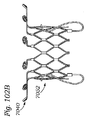
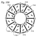
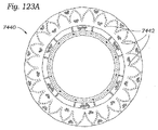
いくつかの例では、植え込み可能な人工弁は、径方向に折畳み可能および径方向に拡張可能な環状のフレームと、フレームの内部に支持される弁部材とを備える。いくつかの例では、フレームは、貫通するルーメンを画成する環状本体と、本体の心室端部部分に結合された少なくとも1つの心室固定部と、本体に結合され本体から離れるように径方向に延在する心房部分とを備え、心房部分は、複数の径方向に延在するアームを備え、アームの少なくとも1つは、蛇行状またはコイル状のセグメントを備える。 In some examples, the implantable prosthesis comprises a radially foldable and radially expandable annular frame and a valve member supported within the frame. In some examples, the frame has an annular body that defines a penetrating lumen, at least one ventricular fixation that is attached to the ventricular end of the body, and a radial orientation that is attached to and away from the body. It comprises an extending atrial portion, which comprises a plurality of radially extending arms, at least one of which comprises a meandering or coiled segment.
いくつかの例では、アームの少なくとも1つが、複数の実質的に直線状の平行セグメントを備える蛇行状セグメントを備える。いくつかの例では、アームの少なくとも1つが、複数の実質的に湾曲状の部分を備える蛇行状セグメントを備える。いくつかの例では、アームの少なくとも1つが、本体の近位のアームの部分に複数の実質的に直線状の平行セグメントを、およびアームの末端部分に複数の実質的に湾曲状の部分を備える、蛇行状セグメントを備える。いくつかの例では、アームの少なくとも1つが、アームの末端部分から本体の近位のアームの部分にかけて増大する厚さを有する蛇行状セグメントを備える。 In some examples, at least one of the arms comprises a meandering segment with a plurality of substantially linear parallel segments. In some examples, at least one of the arms comprises a meandering segment with a plurality of substantially curved portions. In some examples, at least one of the arms comprises a plurality of substantially linear parallel segments at a portion of the arm proximal to the body and a plurality of substantially curved portions at the end of the arm. , With meandering segments. In some examples, at least one of the arms comprises a meandering segment with an increasing thickness from the end portion of the arm to the portion of the arm proximal to the body.
いくつかの例では、複数のアームは、金属セグメントが隣接するアームを相互連結することなく、相互に独立して本体に連結される。いくつかの例では、各アームは、湾曲状または円形の要素を備える自由端部分を有する。いくつかの例では、湾曲状または円形の要素は、本体に向かって径方向に内方に向く2つの末端部分を備える馬蹄形状要素を備える。いくつかの例では、2つの末端部分のそれぞれが、貫通して形成された穴を有するループを備える。いくつかの例では、各アームが、本体に対しておよび隣接するアームに対して可撓性を有する単一金属ワイヤまたはコイルを備える。いくつかの例では、アームの少なくとも1つが、コイル状セグメントを備える。 In some examples, the plurality of arms are connected to the body independently of each other, without the metal segments interconnecting adjacent arms. In some examples, each arm has a free end portion with curved or circular elements. In some examples, the curved or circular element comprises a horseshoe-shaped element having two end portions that point radially inward towards the body. In some examples, each of the two end portions comprises a loop with a hole formed through it. In some examples, each arm comprises a single metal wire or coil that is flexible with respect to the body and to adjacent arms. In some examples, at least one of the arms comprises a coiled segment.
いくつかの例では、心臓の天然僧帽弁領域にプロテーゼ装置を植え込むための方法が、送達装置の遠位端部分内の天然僧帽弁領域にプロテーゼ装置を送達するステップと、プロテーゼ装置の心室固定部を露出させるために送達装置の外方シースを後退させるステップと、送達装置から離れるように径方向に心室固定部を強制的に拡張するステップと、心室固定部が天然僧帽弁尖の背後に移動するように、天然僧帽弁を通してプロテーゼ装置を前進させるステップと、送達装置に向かって径方向に心室固定部を収縮させるステップと、送達装置の内方シースを後退させ、それによりプロテーゼ装置の本体が天然僧帽弁内で径方向に拡張するのを可能にするステップと、を含む。 In some examples, the method for implanting the prosthesis device in the natural mitral valve region of the heart is the step of delivering the prosthesis device to the natural mitral valve region within the distal end of the delivery device and the ventricles of the prosthesis device. The step of retracting the outer sheath of the delivery device to expose the fixation, the step of forcibly expanding the ventricular fixation in the radial direction away from the delivery, and the ventricular fixation of the natural mitral valve leaflet. The step of advancing the prosthesis device through the natural mitral valve to move backward, the step of contracting the ventricular fixation in the radial direction toward the delivery device, and the step of retracting the inner sheath of the delivery device, thereby retracting the prosthesis. Includes steps that allow the body of the device to expand radially within the natural mitral valve.
いくつかの例では、外方シースを後退させるステップは、固定部を強制的に拡張させる固定部スプレッダを露出させる。いくつかの例では、固定部スプレッダは、内方シースに結合され、外方シースを後退させるステップは、固定部スプレッダが内方シースから径方向に弾性的に延在するのを可能にし、それにより固定部を強制的に拡張させる。いくつかの例では、内方シースを後退させるステップは、内方シースを部分的に後退させ、それにより、本体が拡張される前に、プロテーゼ装置の心房部分が径方向に拡張するのを可能にするステップを含む。いくつかの例では、内方シースを後退させるステップは、内方シースを完全に後退させ、それによりプロテーゼ装置の本体部分が径方向に拡張するのを可能にするステップをさらに含む。 In some examples, the step of retracting the outer sheath exposes a fixation spreader that forces the fixation to expand. In some examples, the fixation spreader is attached to the inner sheath and the step of retracting the outer sheath allows the fixation spreader to elastically extend radially from the inner sheath, which. Forcibly expands the fixed part. In some examples, the step of retracting the inner sheath partially retracts the inner sheath, which allows the atrial portion of the prosthesis device to expand radially before the body is expanded. Includes steps to make. In some examples, the step of retracting the inner sheath further includes the step of retracting the inner sheath completely, thereby allowing the body portion of the prosthesis device to expand radially.
いくつかの例では、方法が、患者の心臓の天然僧帽弁領域に配向デバイスを導入するステップと、配向デバイスのエコー発生アームを展開するステップと、心エコー図検査を利用して天然僧帽弁領域内の配向デバイスのエコー発生アームを視認するステップと、天然僧帽弁のA2領域およびP2領域に整列するように配向デバイスのアームを配向するステップと、アームがA2領域およびP2領域に整列される場合に、配向デバイスを通り延在するラインに沿って蛍光透視鏡の蛍光透視鏡軸を整列させるステップと、患者の心臓から配向デバイスを除去するステップと、天然僧帽弁領域にプロテーゼ装置を導入するステップと、A2領域およびP2領域の一方の天然僧帽弁尖の中の1つの背後にプロテーゼ装置の固定部を位置決めするステップであって、固定部は蛍光透視鏡で視認可能である、ステップと、を含む。 In some examples, the method utilizes the step of introducing an orientation device into the natural mitral valve region of the patient's heart, the step of deploying the echo-generating arm of the alignment device, and the natural mitral valve using echocardiography. A step of visually recognizing the echo-generating arm of the alignment device in the valve region, a step of aligning the arm of the alignment device so as to align with the A2 and P2 regions of the natural mitral valve, and the arm aligning with the A2 and P2 regions. If so, a step of aligning the fluorescent fluoroscope axis of the fluorescent fluoroscope along a line extending through the alignment device, a step of removing the alignment device from the patient's heart, and a prosthesis device in the natural mitral valve region. And the step of positioning the fixation of the prosthesis device behind one of the natural mitral valve leaflets in one of the A2 and P2 regions, the fixation being visible with a fluorescent fluoroscope. , Steps, and include.
いくつかの例では、エコー発生アームは、配向デバイスのシャフトの遠位端部分から離れるように径方向に延在する2つのエコー発生アームを備える。いくつかの例では、シャフトの遠位端部分は、中に配設された第1の孔および第2の孔を有する蛍光透視マーカバンドをさらに備え、蛍光透視鏡軸を整列させるステップは、第1の孔から第2の孔に延在するラインに蛍光透視鏡軸を整列させるステップを含む。 In some examples, the echo-generating arm comprises two echo-generating arms that extend radially away from the distal end portion of the shaft of the alignment device. In some examples, the distal end portion of the shaft further comprises a fluoroscopy marker band having a first hole and a second hole disposed therein, and the step of aligning the fluoroscopy axis is a first step. It comprises aligning the fluoroscopy axis with a line extending from the first hole to the second hole.
本発明の前述のおよび他の目的、特徴、および利点は、添付の図面を参照として進められる以下の詳細な説明からさらに明らかになろう。 The aforementioned and other objects, features, and advantages of the present invention will become clearer from the following detailed description, which proceeds with reference to the accompanying drawings.
本明細書では、ヒトの心臓の僧帽弁領域に植え込まれるように主に意図された人工弁およびその構成要素と、これらを植え込むための装置および方法との実施形態が説明される。人工弁は、欠陥を有する天然弁の機能を修復および/または置換するのを補助するために使用され得る。 Hereinafter, embodiments of artificial valves and components thereof primarily intended to be implanted in the mitral valve region of the human heart and devices and methods for implanting them are described. Artificial valves can be used to assist in repairing and / or replacing the function of a defective natural valve.
ヒトの心臓
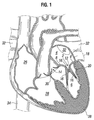
ヒトの心臓の関連部分が図1および図2に示される。健康な心臓は、下方尖部38に向かってテーパ状をなす略円錐形状を有する。心臓は、4つの空洞に分けられ、左心房4、右心房26、左心室6、および右心室28を備える。心臓の左側および右側は、中隔30と一般的に呼ばれる壁部により隔てられる。ヒトの心臓の天然僧帽弁2は、左心室6に左心房4を連結する。僧帽弁2は、大動脈弁14などの他の天然心臓弁とは非常に異なる解剖学的構造を有する。
Human Heart The relevant parts of the human heart are shown in FIGS. 1 and 2. A healthy heart has a substantially conical shape that tapers towards the
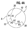
僧帽弁2は、僧帽弁口を囲む天然弁組織の環状部分である弁輪部分8と、弁輪8から左心室6内に下方に延在する1対の心臓弁膜尖、すなわち弁尖10、12と、を備える。僧帽弁輪8は、「D字」形状、長円形状、または長軸および短軸を有する他の真円ではない断面形状を形成し得る。図4Aで概略的に示されるように、前方弁尖10は、後方弁尖12よりも大きいことが可能であり、これらが共に閉じられた場合には弁尖の当接する自由エッジ同士の間に略「C字」形状境界を形成することができる。図4Bは、僧帽弁逆流および/または他の望ましくない症状に至り得る完全には閉じることができない欠陥を有する天然僧帽弁によってなど、弁尖10、12間に若干の間隙3を有する天然僧帽弁2を示す。
The
適切な動作時には、前方弁尖10および/または後方弁尖12は、一方向弁として共に機能して、左心房4から左心室6へのみ血液を流し得る。左心房4は、肺静脈32から酸素化血液を受ける。左心房4の筋肉が収縮し、左心室が拡張すると、左心房4内に収集された酸素化血液は、左心室6に流入する。左心房4の筋肉が弛緩し、左心室6の筋肉が収縮すると、左心室内の上昇した血圧により2つの弁尖が共に付勢され、それにより一方向僧帽弁が閉じられ、それにより血液は、左心房に逆流することが不可能となり、代わりに大動脈弁14を通り左心室から押し出される。
When properly operated, the
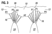
2つの弁尖10、12が圧力下で逸脱し、左心房4に向かって僧帽弁輪8を通り折れ戻るのを防止するために、腱索16と呼ばれる複数の線維索が、左心室6の乳頭筋に弁尖10、12を繋ぎ留める。図3および図4を参照すると、腱16が、後内側乳頭筋22と前方弁尖10および後方弁尖12の両方の後内側縁部(カーペンティア名(Carpentier nomenclature)により特定されるようなA1エリアおよびP1エリアのそれぞれ)とに付着され、それらの間に延在する。同様に、腱16は、前外側乳頭筋24と前方弁尖10および後方弁尖12の両方の前外側縁部(カーペンティア名により特定されるようなA3エリアおよびP3エリアのそれぞれ)とに付着され、それらの間に延在する。A2エリアおよびP2エリアは、腱付着点からは比較的自由であり、人工僧帽弁が固定され得る領域を提供する(図3を参照)。さらに、これらの腱の編成は、人工僧帽弁を送達するためのアプローチ経路において腱の絡み合いリスクを最小限に抑える。
To prevent the two
人工弁
天然僧帽弁が適切に機能することができない場合に、人工弁置換は、適切な機能の修復を補助することが可能である。しかし、比較的円形で堅い弁輪を有する(特に大動脈狭窄症の場合)大動脈弁14と比較すると、僧帽弁輪8は、比較的堅さに劣り、より不安定であり得る。結果として、天然僧帽弁輪8に対して押圧される人工弁の外方表面の径方向力による摩擦のみに依存することによって、主として大動脈弁用に設計された人工弁を天然僧帽弁輪8内に固定することは、不可能となり得る。したがって、本明細書において説明される人工弁は、天然僧帽弁輪8内に人工弁を固定するために、径方向摩擦力の代わりにまたはそれに加えて、心室固定部に依存し得る(例えば図23を参照)。
Artificial valve If the natural mitral valve is unable to function properly, prosthetic valve replacement can assist in the restoration of proper function. However, the
人工弁に固定手段を与えることに加えて、心室固定部は、僧帽弁逆流の根本原因、すなわち左心室拡大症/拡張症の治療を助けるために、左心室6をリモデリングすることもまた可能である。心室固定部は、天然僧帽弁尖10、12を共により近くにおよび左心房に向かって引くことが可能であり、ならびに腱16を介することでそれにより乳頭筋22、24を共により近くに引くことが可能となり、これによって、心室を急激に好適にリモデリングし、左心室がさらに拡大するのを防止し得る。したがって、心室固定部は、張力部材または再成形部材とも呼ばれ得る。
In addition to providing a means of fixation to the prosthetic valve, the ventricular fixation site can also remodel the
図5〜図7は、天然僧帽弁2の機能を置換するために心臓の天然僧帽弁領域に植え込まれ得る一実施形態による例示の人工弁100を示す。人工弁100は、フレーム102と、フレームによりおよび/またはフレーム内に支持される弁構造体104とを備える。弁構造体104は、複数の後方弁尖106(図示される実施形態では3つ)および/または人工弁100を通る一方向への血流を調整するための他の構成要素を備えることが可能である。例えば、図5および図6では、弁構造体104は、弁構造体の上方端部110が流入端部となり、弁構造体の下方端部112が流出端部となるように、フレーム102内に配向される。弁構造体104は、天然組織(例えばウシ心膜組織)または合成材料などの様々な適切な材料の任意のものを含むことが可能である。弁構造体104は、適切な技術および機構を利用してフレーム102に取り付けられ得る。例えば、図示する実施形態では、弁尖106は、図7に示すように三尖構造でフレーム102に縫合される。
5 to 7 show an exemplary
人工弁の構成要素およびアセンブリに関するさらなる詳細(フレームに弁尖を取り付けるための技術を含む)は、例えば特許文献2および特許文献3などに記載される。これらは、参照により本明細書に組み込まれる。
Further details regarding the components and assembly of the artificial valve (including techniques for attaching the valve leaflets to the frame) are described, for example, in
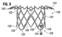
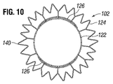
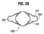
図8〜図10に示すように、フレーム102は、管状本体122と、本体の心室端部130から延在する1つまたは複数の心室固定部126と、任意には本体の心房端部132から径方向に外方に延在する心房封止部材124とを備えることが可能である。図23に示すように、フレーム102が心臓の天然僧帽弁領域に植え込まれる場合には、本体122は、本体122の心室端部130が下方出口端部となり、本体122の心房端部132が上方入口端部となり、心室固定部126が左心室6内に配置され、心房封止部材124が左心房4内に配置される状態で、天然僧帽弁輪8内に位置決めされる。
As shown in FIGS. 8-10, the
フレーム102は、ワイヤメッシュから作製され得ると共に、心臓の僧帽弁領域に(または別の天然心臓弁内に)送達するおよび植え込むことを可能にするために、(図11〜図16および図17〜図22にて一連の連続段階で概略的に図示されるように)径方向拡張状態と径方向圧縮状態との間で径方向に折畳み可能および拡張可能とすることができる。図11〜図22に示すフレーム102の実施形態は、心房封止部材124を備えないが、フレーム102の他の実施形態は、心房封止部材124を備える。ワイヤメッシュは、例えば図8〜図10に示す鋸刃パターンまたはジグザグパターンなどの格子パターンで構成された金属ワイヤまたは金属ストラットを備えることが可能であるが、他のパターンもまた利用され得る。フレーム102は、径方向圧縮状態から拡張状態に自動拡張することを可能にするために、例えばニチノールなどの形状記憶材料を含むことが可能である。代替的な実施形態では、フレーム102は、例えば膨張性バルーン(図示せず)などの拡張デバイスにより径方向圧縮状態から拡張状態に可塑的に拡張可能とすることができる。かかる可塑的に拡張可能なフレームは、ステンレス鋼、クロム合金、および/または他の適切な材料を含むことが可能である。
The
図8〜図10に示すように、拡張状態では、フレーム102の本体122は、開端部チューブを形成し得る。弁構造体104は、以下で論じるようにフレームの内方表面上の材料層142を介してなど、フレーム102の内方表面に結合され得ると共に、図7に示すように本体122によって形成されるルーメン内に保持され得る。本体122の外方表面は、僧帽弁口、すなわち僧帽弁輪8の内方表面と同様の寸法を有することが可能であるが、必ずしもそうであるとは限らない。いくつかの実施形態では、例えば、本体122の外方表面は、図23におけるように天然僧帽弁輪8を実質的に伸張させることなく本体122が拡張状態で僧帽弁口内に嵌り得るように、天然僧帽弁口の直径寸法よりも小さな直径寸法を有することが可能である。かかる実施形態では、フレーム102は、人工弁の保持のために、本体122の外方表面と僧帽弁輪8の内方表面との間の圧力嵌めまたは摩擦嵌めに依存する必要はない。代わりに、フレーム102は、以下でさらに説明されるように、保持のために心室固定部126および/または心房封止部材124に依存することが可能である。しかし、他の実施形態では、本体122は、天然僧帽弁口と同等のまたはそれ以上のサイズにまで拡張し、それにより植え込み時に圧力嵌めを形成するように構成され得る。
As shown in FIGS. 8 to 10, in the expanded state, the
本体122が天然僧帽弁口の直径寸法よりも小さな直径寸法を有する実施形態では、本体は、天然弁尖10、12間で緩く着座し得る、または「遊動」し得る。図4Cに示すように、この緩い嵌めは、弁尖10、12とフレームの本体122との間に間隙37を形成し得る。間隙37を通してなど、人工弁100の外部と天然弁組織との間における血流を防止するために、環状心房封止部材124は、僧帽弁輪8の心房側の天然組織との間に完全に環状の接触エリアまたはシールを形成し得る。したがって、図4Dに示すように、心房封止部材124は、間隙37を完全に覆うようにサイズ設定され得る。
In embodiments where the
フレーム102の端部は、図8〜図10に示すように、例えばそれらの上方端部にて共に連結される一連の横並び「V字」形状部分を備える鋸刃パターンまたはジグザグパターンを有することが可能である。このパターンは、圧縮を容易化することが可能であり、フレームを天然組織に連結させるための表面積を最大化するのを補助し得る。代替的には、フレーム102の端部は、直線状エッジまたは何らかの他のパターンを有することが可能である。
The ends of the
いくつかの実施形態では、本体122は、本体122の心室端部130から下方に延在する少なくとも1つの延長部材または押し部材を備えることが可能である。例えば図25に示すフレーム202は、本体222の「V字」形状部分の中の1つの下方頂点から延在するプロング204の形態の延長部材を備える。プロング204は、下方押し表面206を備える上下逆さまの「T字」形状を有することが可能である。別の実施形態では、図26に示すフレーム302は、本体322の2つの隣接し合う下方頂点から延在し押し表面306を備える「V字」形状押し部材304を備える。押し表面206および押し表面306は、フレーム202およびフレーム302のそれぞれに最下点を備えることが可能であり、以下でさらに詳細に説明されるように心室固定部226、326に接触することなくフレームが送達デバイスから押し出されるようにするための押し表面を提供し得る。
In some embodiments, the
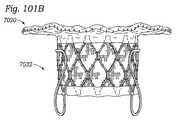
図8〜図10に示す実施形態を再度参照すると、フレーム102の心房封止部材124は、本体122と一体であることが可能であり、心房封止部材124もまた径方向に折畳み可能および拡張可能になるように本体122と同一のワイヤメッシュ格子から構成することが可能である。拡張状態では、心房封止部材124は、略裁頭円錐形であることが可能であり、本体122の心房端部132から径方向に外方および軸方向に下方の両方に本体122の心室端部130に向かって延在し得る。心房封止部材124の外方リム140は、図23に示すように、フレーム102が植え込まれる場合に、僧帽弁輪の心房側および左心房4の組織に接触するようにサイズ設定および形状設定され得る。図10に示すように、外方リム140の端面図プロファイルは、心房壁18および僧帽弁輪8の天然ジオメトリに略対応するほぼ円形形状、長円形状、または他の形状を有することが可能である。心房封止部材124と心房壁18および/または僧帽弁輪8の組織との間の接触は、フレームへの組織内部成長を促進し得るため、これは保持を改善し、弁傍漏出を減少させ得る。
With reference to the embodiments shown in FIGS. 8 to 10, the
望ましくは、心房封止部材124は、人工弁100が図23に示すように天然僧帽弁に植え込まれる場合に、外方リム140が天然弁全体の周囲で天然弁輪8に接触し、したがって天然弁尖10、12間の開口を完全に覆うようにサイズ設定される。望ましくは、心房封止部材124は、血流に対して不透過性を有する封止層142を備える。このようにすることで、心房封止部材124は、人工弁100の外方表面と天然弁組織との間で左心房内に血液が逆流するのを阻止することが可能となる。また、心房封止部材は、すべてのまたは実質的にすべての血液が、左心房から左心室に流れる場合に一方向弁を通過するのを確実にする。
Desirably, the
図5〜図7に示すように、少なくとも1つの生体適合性シートまたは生体適合性層142が、ワイヤメッシュの開口を覆う少なくとも1つの層またはエンベロープを形成するために、本体122および心房封止部材124の内方表面および/または外方表面に連結され得る。層142は、例えば縫合糸によりフレーム102に連結され得る。層142は、弁傍漏出を減少させるためにワイヤメッシュを通過する血流を少なくとも部分的に阻止することが可能な、およびフレーム102への組織内部成長を促進することが可能な流体遮断および/または封止部材を形成することが可能である。層142は、弁尖106などの弁構造体104の部分が固定され得る取付表面または足場を提供し得る。例えば、図5および図6の破線108は、弁尖106の入口端部が層142に縫い付けられ得る、縫合され得る、または他の方法で固定され得る位置を表す。弁尖106の入口端部と層142との間のこのシームは、層142の内周部の周囲にて連続し、層142の内方表面と弁尖106の外方表面との間の血流を阻止し得るシールを形成することが可能である。このシールにより、人工弁100は、複数の弁尖106同士の間を流れるように血液を送ることが可能となり得る。
As shown in FIGS. 5-7, the
また、同層142および/または1つまたは複数の独立カフ144が、本体122の心室端部130および/または心房封止部材124の外方リム140などの、フレーム102の端部エッジの周囲を囲むまたはその端部エッジを覆うことが可能である。かかるカフ144は、フレーム102の端部の先鋭エッジを覆うおよび保護することが可能である。例えば、図5に示す実施形態では、層142は、外方リム140から心房封止部材124の上方表面を越えておよび本体122の内方表面に沿って下方に延在し、本体122心室端部部分の周囲を囲みその心室端部部分を覆うカフ144を備える。層142は、外方リム140におよび本体122の内方表面に縫合され得る。
Also, the
層142は、血流を阻止するが組織内部成長を許容し得る半多孔性布地を含むことが可能である。層142は、ポリエステル材料または生体適合性ポリマーなどの合成材料を含むことが可能である。ポリエステル材料の一例は、ポリエチレンテレフタレート(PET)である。代替的な材料が使用され得る。例えば、層は、天然組織、心膜組織(例えばウシ心膜、ブタ心膜、またはウマ心膜)、または他の生体組織などの生体物質を含むことが可能である。
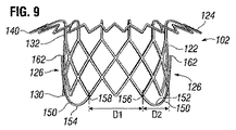
図8および図9を参照すると、1つまたは複数の心室固定部126が、本体の心室端部130からなどフレーム102の本体122から延在し得る。心室固定部126は、心臓の天然弁領域内で、弁構造体104と共にまたは弁構造体104を伴わずにフレーム102を保持するように機能することが可能である。図8および図9に示す実施形態では、フレーム102は、図23に示すようにフレーム102が僧帽弁領域に植え込まれる場合に、前方僧帽弁尖10および後方僧帽弁尖12のそれぞれにフレーム102を固定するように機能し得る2つの直径方向に対向する心室固定部126を備える。代替的な実施形態では、フレーム102は、フレームの本体122の周囲で角度離間され得る3つ以上の心室固定部126を有することが可能である。
With reference to FIGS. 8 and 9, one or more
図9におけるようにフレーム102が拡張状態にある場合には、フレームのジオメトリにより、心室固定部126は本体122の外方表面に対して付勢され得る。代替的には、心室固定部126は、フレーム102が拡張状態にある場合に、本体122の外方表面から離間されるように構成され得る(例えば図39を参照)。いずれの場合でも、フレーム102が圧縮状態へと径方向に圧縮されると、心室固定部126と本体122の外方表面との間の空間または間隙は、図11〜図16に示すように増大し得る。
When the
本体122および心房封止部材124が圧縮状態にある間に、フレーム102は、離間された心室固定部126が弁尖10、12の周囲を囲み、弁尖と心室壁20との間で上方に延在するように、僧帽弁口に挿入され得る(例えば図59を参照)。図23を参照すると、前方心室固定部146が前方弁尖10の背後に配置され、後方心室固定部148が後方弁尖12の背後に配置され得る。図3および図4を参照すると、望ましくは、2つの心室固定部は、2つの弁尖が合流する交連部36同士の間のほぼ中間点である弁尖の中間部分A2、P2の付近にて各弁尖の背後に配置される。弁尖10、12のこれらの中間部分A2、P2は、望ましい心室固定部位置である。なぜならば、弁尖への腱索16付着部が、交連部36により近い位置の場合と比較してこれらの位置ではより散在的になるからである。
While the
本体122が、図11〜図16に示すのとは逆順で後に拡張されるかまたは拡張状態へと自動拡張され得る場合には、心室固定部は、心室固定部に対する外部圧縮力を伴わずに本体122に対して径方向に内方に枢動するように構成される。これにより、心室固定部126と本体122の外方表面との間の間隙は縮小し、それにより心室固定部と本体との間に弁尖10、12を捕獲することが可能となる。対照的に、本体122を圧縮することにより、心室固定部126は本体から離れるように枢動して、本体の外方表面と心室固定部との間の間隙が増大する。いくつかの実施形態では、心室固定部126の自由端部または尖部162は、本体122が心室固定部に対する外部力がない状態で径方向に圧縮または拡張される場合に、相互に実質的に同一距離を置いて離間された状態に留まることが可能である。図23に示す実施形態などのいくつかの実施形態では、フレームは、フレームが拡張状態へと拡張した場合に、本体と心室固定部との間で天然僧帽弁尖10、12を圧縮するように構成される。図39に示す実施形態などの他の実施形態では、心室固定部は、本体に対して天然弁尖を圧迫または圧着させないが、天然弁尖10、12の周囲の心室固定部の掛合により人工弁が左心房に向かって移動するのを依然として防止する。かかる実施形態では、人工弁100は、以下でさらに説明されるように、心房封止部材124により左心室への移動に対して定位置に保持され得る。
If the
図8〜図10に示す実施形態を参照すると、各心室固定部126は、例えばニチノールなどの形状記憶材料から構成された可撓性の細長部材またはワイヤ150を備えることが可能である。図8に示すようないくつかの実施形態では、各ワイヤ150が、本体122の第1の付着位置156に結合された第1の端部部分152と、本体の第2の付着位置158に結合された第2の端部部分154とを備えることが可能である。第1の端部部分152および第2の端部部分154は、心室固定部のベースを形成する。本体の第1の付着位置152および第2の付着位置154は、本体122の心室端部130にまたはそれに隣接して位置し得る。各ワイヤ150の2つの端部部分152、154は、本体122の格子メッシュを構成するワイヤまたはストラットの延長部分とすることが可能である。各ワイヤ150は、端部部分152、154間で本体の長さ方向に延在する中間部分160をさらに備える。中間部分160は、心室固定部の自由端部分または尖部を形成する屈曲部162を備える。
With reference to the embodiments shown in FIGS. 8-10, each
ワイヤ150は、多角形断面プロファイルなど、ワイヤの長さに対して垂直な円形または非円形の断面プロファイルを有することが可能である。図8Aを参照すると、ワイヤ150は、長さ「L」および比較的幅狭の幅「W」を有する矩形断面形状を備えることが可能であり、フレーム102に付着した心室固定部126の2つの端部部分152、154が、フレームの圧縮時などに相互方向へと移動される場合には、ワイヤ150は、主に幅方向に曲がる。これは、本体122から径方向に外方に離れる方向へと心室固定部126の曲りを助長して、心室固定部126と本体122との間の間隙を広げる。この特徴は、植え込み時に心室固定部126と本体122との間の弁尖を捕獲するのを補助し得る。
The
心室固定部は、様々な形状または構成を備えることが可能である。図8に示すフレーム102などのいくつかのフレーム実施形態は、2つの付着位置156、158にて本体122に連結する略「U字」形状または略「V字」形状の心室固定部126を備える。心室固定部126の上方尖部162は、腱の絡み合いリスクを最小限に抑えつつ、各弁尖の背後への心室固定部の移動を容易にするためのウェッジのように機能し得る。各ワイヤ150の端部部分152、154は、本体122の心室端部130で付着位置156、158のそれぞれから下方に延在し得る。次いで、ワイヤ150は、各端部部分152、154から尖部162に向かって上方に湾曲して戻り得る。
The ventricular fixation can come in a variety of shapes or configurations. Some frame embodiments, such as the
ワイヤ150は、例えば図5〜図7に示す実施形態におけるように生体適合性材料によって覆われ得る。第1の材料164は、ワイヤ150の少なくともある部分の周囲を囲むまたはその部分を被覆することが可能である。第2の材料166は、ワイヤ150の2つの部分にわたって広がりウェブを形成することが可能であり、このウェブは、組織内部成長を向上させ得る。第1の材料164および第2の材料166は、例えば生体適合性半多孔性布地などの、同一の材料または異なる材料を含むことが可能である。被覆材料164、166は、心室固定部126への組織内部成長を増大させて、保持を向上させる。さらに、これらの被覆材料は、心室固定部126の摩擦特性を低減させて植え込みを容易化させることが可能である、および/または心室固定部の摩擦特性を増大させて保持を向上させることが可能である。
The
図24は、図9に示すフレーム102の実施形態の例示の寸法を示す。心房封止部材124の外方リム140の直径「Dmax」は、約50mm〜約70mmの範囲とすることが可能であり、一例では約50mmである。本体122の外方表面の直径「Dbody」は、約23mm〜約50mmの範囲であることが可能であり、一例では約29mmである。1つの心室固定部126に関する2つの付着点156、158間の距離「W1」は、約8mm〜約50mmの範囲とすることが可能であり、一例では約25mmである。フレーム102の軸方向全高「Hmax」は、約20mm〜約40mmの範囲とすることが可能であり、一例では約30mmである。心室固定部126の外方リム140から最下部分168までの軸方向高さ「H1」は、約10mm〜約40mmの範囲とすることが可能であり、一例では約23mmである。心室固定部126の尖部162から心室固定部126の最下部分168までの軸方向距離「H2」は、約10mm〜約40mmの範囲とすることが可能であり、一例では約18mmである。本体122の下方端部130から心室固定部126の最下部分168までの軸方向距離「H3」は、約0mm〜約10mmの範囲とすることが可能であり、一例では約5mmである。
FIG. 24 shows exemplary dimensions of the embodiment of
いくつかのフレームの実施形態は、3つ以上の心室固定部を備える。例えば、フレームが、天然弁の単一の弁尖に沿って複数の位置に装着するように構成された2つ以上の心室固定部を有することが可能である。いくつかのかかる実施形態では(図示せず)、フレームは、前方僧帽弁尖10に装着する2つの心室固定部を、および/または後方僧帽弁尖12に装着する2つの心室固定部を備えることが可能である。また、心室固定部は、A2領域およびP2領域の代わりにまたはそれらに加えて弁尖の他の領域に装着することも可能である。
Some frame embodiments include three or more ventricular fixation sites. For example, the frame can have two or more ventricular fixation sites configured to fit in multiple positions along a single leaflet of a natural valve. In some such embodiments (not shown), the frame comprises two ventricular fixations attached to the anterior
いくつかの人工弁実施形態は、本体の周囲に均等に離間された4つの心室固定部を備える。図27〜図32は、本体422の直径方向に対向する両側(diametrically opposed sides)の1対の心室固定部426と、心室固定部426同士の間の略中間点に配置された1対の直径方向に対向する交連固定部428と、を含むフレーム402を備える1つの、かかる人工弁実施形態400を示す。心室固定部426は、付着点456および458から下方に延在し、ネック部分450を備える(図31を参照)。これらの心室固定部426は、フレーム102の心室固定部126と同様に機能して、図33に示すように弁尖を捕獲し僧帽弁口内にフレーム402を保持する。交連固定部428は、本体422上の同一の付着位置456、458から上方に延在し得る(図30を参照)。心室固定部426は、A2領域およびP2領域のそれぞれにて僧帽弁尖10、12をクリップ留めすることが可能である一方で、交連固定部428は、僧帽弁交連部36の周囲に掛合し、僧帽弁交連部36の背後にて上方に延在することが可能であり、弁尖を圧迫しない。交連固定部428の尖部464は、上方に延在して僧帽弁輪8の心室側に当接し、心房封止部材424の外方リム440と交連固定部428の尖部464との間で僧帽弁輪8を圧迫することが可能である。僧帽弁輪8のこの圧迫は、心房および心室の両方の移動を防ぐために追加的な保持を与え得る。
Some prosthetic valve embodiments include four ventricular fixation portions evenly spaced around the body. 27-32 show a pair of diametrically opposed sides of the
他のフレーム実施形態は、5つ以上の心室固定部を備えることが可能である。例えば、フレームが、弁尖10、12および/または交連部36の上の複数の位置に係合し得る6つ以上の心室固定部を備えることが可能である。
Other frame embodiments can include five or more ventricular fixation sites. For example, the frame can include six or more ventricular fixations that can engage at multiple positions on the
図34は、弁尖10、12の端部の周囲に延在し、下方に延在する裁頭円錐形心房封止部材524の外方リム540の近位の位置まで弁尖の背後にて上方に延在するように構成された、延伸された心室固定部526を備えるフレーム502の実施形態を示す。延伸された心室固定部526の上方尖部562は、僧帽弁輪8の心室表面および/または弁輪もしくは弁尖の弁輪連結部分に隣接する天然弁尖10、12の部分に接触する一方で、心房封止部材524の外方リム540は、僧帽弁輪の心房表面および/または弁尖の弁輪連結部分に接触する。延伸された心室固定部526および心房封止部材524は、相互に対向するように構成され得るものであり、望ましくは僧帽弁輪8および/または弁尖10、12の弁輪連結部分を圧迫して心房方向および心室方向の両方への移動を防ぐようにフレーム502を保持する。したがって、この実施形態では、心室固定部526は、フレームの本体522の外方表面に対して天然弁尖10、12を圧迫する必要はない。代わりに、図34に示すように、弁尖10、12は、延伸された心室固定部526と本体522の外方表面との間に緩く捕獲され得る。
FIG. 34 is behind the valve leaflets to a position proximal to the
図35および図36は、ネックを有する「S字」形状心室固定部626を備えるフレーム実施形態602を示す。図35の側面図からは、心室固定部626の「S字」形状が明らかである。心室固定ワイヤ650は、本体622の心室端部630上の1つの付着点Aから起始して、本体から点Bまで下方におよび径方向に外方に延在し、次いで点Cまで上方におよび外方に湾曲し、次いで点Dまで上方におよび内方に湾曲し、次いで最上点または尖部Eまで上方におよび外方に戻るように湾曲する。次いで、心室固定ワイヤ650は、同様のしかし鏡像状の経路にしたがって第2の付着点に延在して戻るまで続く。図36の正面図からは、心室固定ワイヤ650は、本体622の中心を通り延在する長手方向中心軸690の周囲で対称をなすネック形状を形成して、鏡像半部を形成する。心室固定ワイヤ650の各半部は、本体622の心室端部630上の付着点Aにて起始し、点Bまで下方におよび内方に(他方の半部に向かって)湾曲し、次いで点Cのネック部分まで上方におよび内方に湾曲し、次いで点Dまで上方におよび外方に(他方の半部から離れるように)湾曲し、次いで2つの半部が共に接合する最上点または尖部Eまで再び上方におよび内方に湾曲する。図35を参照すると、本体622の長手方向中心軸690から点Cおよび点Eまでの径方向距離はいずれも、軸690から点Dまでの径方向距離よりも大きい。さらに2つの点C間の距離は、2つの点D間の距離よりも小さい。「S字」形状心室固定部626は、ワイヤ650に沿って応力をより均一に分散し、付着点Aなどのいくつかの位置における応力集中を軽減するのを補助し得る。
35 and 36 show a
図37および図38は、2つのより幅広形状の心室固定部726を備えるフレーム実施形態702を示す。各より幅広形状の心室固定部726は、ネック中央部分780と幅広上方部分782とを備える。上方部分782は、フレーム702の流入開口に対して略平行に延在することが可能であり、本体722の外方表面の周囲で湾曲し得る。この、より幅広の形状は、天然弁尖および/または他の心臓組織との表面接触を増加させて、圧力を低下させ、したがって擦過を軽減させ得る。いくつかの実施形態では、より幅広形状の心室固定部726の幅広上方部分782は、組織接触をさらに向上させるために、本体722の外方表面の曲率(図38を参照)に対応する曲率を有することが可能である。より幅広形状の心室固定部は、心房封止部材との、より長い表面接触を有することにより、保持性能を向上させ、弁傍漏出を減少させることが可能である。
37 and 38 show a
図39は、フレーム802の拡張後でも固定部と本体822との間に離間部または間隙を画成するように構成された心室固定部826を備えるフレーム実施形態802を示す(しかし、他の場合には、固定部826は、固定部826とフレーム本体822との間の間隙が本体の圧縮および拡張のそれぞれに応じて増大および縮小し得ることにより、天然弁尖の背後への固定部826の配置を容易にするように、心室固定部126と同様に機能することも可能である)。間隙は、天然弁尖の圧迫を殆どまたは全く伴わずに天然弁尖10、12の捕獲を容易にするようにサイズ設定され得る。弁尖の圧迫が殆どまたは全く生じないため、このフレーム実施形態802は、天然弁尖への外傷を最小限に抑えることが可能である。弁保持のために弁尖10、12を圧迫する代わりに、心室固定部826は、弁尖10、12のそれぞれの心室エッジ40、42に掛合し得る一方で、フレームの心房封止部材824は、僧帽弁輪8の心房側を下方に押圧する。心房封止部材824と弁輪8との間の接触により、本体822は若干上方へとシフトして、弁尖10、12の心室エッジに対して上方に心室固定部826を引く。腱索16からの弁尖に対する下方張力と組み合わされた心室固定部の上方力は、インプラントが左心房4に向かって上方に移動するのを抑制する。
FIG. 39 shows a
図40は、本体922と、心室固定部926と、本体922の上方端部932から径方向に外方に延在する円盤状心房封止部材924とを備えるフレーム実施形態902を示す。この実施形態では、心房封止部材924は、フレームの下方端部930に向かって下方にではなく、上方端部932により画成されたフレーム開口に対して実質的に垂直に延在する。円盤状心房封止部材924は、僧帽弁輪8の頂部表面にわたり平坦に位置決めされ、組織内部成長のための表面エリア接触を増大させ得る。
FIG. 40 shows a
図41および図42は、本体1022の上方端部1032から本体から離れるように径方向に外方および軸方向に上方の両方に延在する略裁頭円錐形部分1028を有する心房封止部材1024を備えるフレーム実施形態1002および1012をそれぞれ示す。また、心房封止部材1024は、本体1022の上方端部1032の対向側の裁頭円錐形部分1028からさらに上方に延在する略円筒状上方部分または入口部分1029を備えることが可能である。心房封止部材1024は、僧帽弁輪8に隣接する心房壁18の形状に略対応し、心房壁組織と心房封止部材1024との間の接触面積を増大させ得る。フレーム1002は、本体1022の心室端部1030からおよび本体の長さの大部分に沿って延在する心室固定部1026を備える。
41 and 42 show an
図42に示すフレーム1012は、延伸された心室固定部1050を備える。延伸された固定部1050は、本体1022の心室端部1030から本体の外方表面に沿って延在し、径方向に外方に曲がって、裁頭円錐形部分1028の下方表面に沿って延在する上方部分1060を形成し得る。この構成は、延伸された心室固定部1050がフレームに対して弁尖10、12および/または僧帽弁輪8のより多くを捕捉するのを可能にし、それにより弁傍漏出を減少させ、組織内部成長および保持を向上させることが可能である。
The
図43は、図9に示すフレーム102の心室固定部126と比較してより短いモーメントアームD2を有する心室固定部1126を有するフレーム実施形態1102を示す。この、より短いモーメントアームD2は、結果として心室固定部付着点1156、1158におけるトルクの低減をもたらし得る。距離D2は、隣接する心室固定部1126の本体1122上の付着点1158および付着点1156間の距離D1を増大させることによって縮小させることが可能である。フレーム1102の心室固定部1126間の距離D1は、フレーム102の付着点158および付着点156間の距離D1(図9を参照)よりも大きく、したがって付着点1156に対する力FのモーメントアームD2を短縮させる。付着点1156および付着点1158のトルクの低減により、疲労が軽減され、したがって、フレーム1102の耐久性が向上し得る。
FIG. 43 shows a
また、任意には、心室固定部のいくつかの実施形態は、心室固定部から心室壁20に向かってまたは弁尖10、12に向かって径方向に突出し得る1つまたは複数の返し(図示せず)を備えることも可能である。かかる返しは、特に左心室6に向かう移動を防止するようにフレームを保持するのを補助し得る。
Also, optionally, some embodiments of the ventricular fixation may be one or more returns that may project radially from the ventricular fixation towards the
図44A〜図44Dは、「跳ね上げ」心室固定部1226を備えるフレーム実施形態1202を示す。各心室固定部1226は、フィンガ状とすることが可能であり、本体1222の下方端部1230上の1つのみの付着点から延在し得る。代替的には、各心室固定部は、本体1222上の2つの付着点から延在するワイヤまたは同様の要素を備えることが可能である。図示する実施形態では、心室固定部1226は、図44Dに示すように、機能的展開状態で本体1222の外方側に沿って延在するように事前形成され得る。送達時には、心室固定部1226は、図44Aに示すように部分的にまたは完全に直線状になされ、シースなどの送達デバイスによりその状態に維持され得る。フレーム1202が例えばシースから前進されることにより、心室固定部1226は、図44B〜図44Dに示すように事前形成形状に跳ね戻り、心室固定部1226と本体1222との間で弁尖10、12を捕獲する。
44A-44D
図45A〜図45Eは、「巻き上げ」心室固定部1326を備えるフレーム実施形態1302を示す。図44の心室固定部1226と同様に、各心室固定部1326は、フィンガ状とすることが可能であり、本体1322の下方端部1330上の2つ以上の点から延在し得る。図45Eに示すように、心室固定部1326は、展開状態で本体1322の側部に沿って延在する湾曲形状に事前形成され得る。送達時には、心室固定部1326は、図45Aに示すように部分的にまたは完全に直線状になされ、シースなどの送達デバイスによりその状態に保持され得る。フレーム1302が例えばシースから前進されることにより、心室固定部1326は、図45B〜図45Eに示すように事前形成湾曲形状に跳ね戻り、心室固定部1326と本体1322との間で弁尖10、12を捕獲し得る。
45A-45E
いくつかのフレーム実施形態では、1つまたは複数の心室固定部構成要素が、本体とは別個に形成され、後に共に組み立てられてフレームを形成し得る。図46A〜図46Cに示すような1つのかかる実施形態1402では、本体1422は、少なくとも1つの心室固定部分1424とは別個に形成される。心室固定部分1424は、少なくとも部分的に環状のベース1432から延在する1つまたは複数の心室固定部1426を備えることが可能であり、この少なくとも部分的に環状のベース1432は、それらの上方端部で共に連結される横並びの「V字」形状ストラット部分を備えることが可能である。図示する実施形態における心室固定部1426の下方端部は、「V字」形状部分の下方頂点にてベース1432に連結される。本体および心室固定部分が別個に形成された後に、心室固定部分1424は、本体1422の下方部分1430に装着され得る。例えば、ベース1432は、本体1422の外方表面の両側に配置され、次いでロック機構の利用によってなど適切な方法で本体1422の下方部分1430に縫い付けられ得る、溶接され得る、または他の方法で装着され得る。ベース1432は、ベースの「V字」形状部分が本体1422の下方端部1430の対応する「V字」形状部分に重畳するように、本体1422に装着され得る。いくつかの実施形態では、心室固定部分1424は、心室固定部同士が相互に対して事前離間されるように、1つの環状ベースから延在する心室固定部1426のすべてを有する完全リングを備えることが可能である。次いで、環状ベースは本体1422の下方部分1430の周りに装着され得る。他の実施形態では、部分リングを備える各ベース1432から延在する1つまたは複数の心室固定部1426をそれぞれが有する複数の心室固定部分1424が、本体1422に固定される。
In some frame embodiments, one or more ventricular fixation components may be formed separately from the body and later assembled together to form the frame. In one
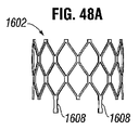
図47A〜図47Dおよび図48A〜図48Cは、1つまたは複数の心室固定部構成要素が本体とは別個に構成され、後に共に組み立てられてフレームを形成する、代替的なフレーム実施形態を示す。これらのフレーム実施形態では、本体は、スリーブを利用して固定部分が装着され得る装着部分を備えることが可能である。例えば、図47A〜図47Dは、少なくとも2つの心室固定部装着部分1508を有する本体1502と、各スリーブ1506により各装着部分1508に連結される2つの装着部分1510を有する少なくとも1つの心室固定部1504とを備える例示のフレーム1500を示す。同様に、図48A〜図48Cは、少なくとも2つの心室固定部装着部分1608を有する本体1602と、各スリーブ1606により各装着部分1608に連結される2つの装着部分1610を有する少なくとも1つの心室固定部1604とを備える例示のフレーム1600を示す。スリーブは、超弾性特徴および/または形状記憶特徴を有する、例えばニチノールなどの金属材料を含むことが可能である。いくつかの実施形態では、スリーブは、圧着プロセスに適したアニール状態の金属を含むことが可能である。スリーブは、溶接によってなど任意の適切な装着手段により固定部分におよび本体の装着部分に装着され得る。図48A〜図48Cに示すように、固定部1604の装着部分1610および本体1602の装着部分1608は、機械式ロックを形成することによってなどスリーブ1606が本体1602に固定部分1604を一体化するのを可能にさせる、幅狭領域または切欠部などの幾何学的特徴を備えることが可能である。
47A-47D and 48A-48C show alternative frame embodiments in which one or more ventricular fixation components are configured separately from the body and later assembled together to form a frame. .. In these frame embodiments, the body can include a mounting portion to which the fixing portion can be mounted using a sleeve. For example, FIGS. 47A-47D show at least one
図46〜図48に示すように、フレームの複数パーツ構造は、単体構造または一体構造と比較して心室固定部装着位置における歪および疲労を軽減させ得る。対照的に、単体構造を備えるいくつかの実施形態では、心室固定部は、初めにレーザ切断され、本体の下方端部から下方に延在するように延伸され、次いでフレームの本体の外部に隣接する所望の構成へと形成または曲げられる。かかる曲げは、屈曲部分を歪ませ脆弱化させ得る。 As shown in FIGS. 46-48, the multi-part structure of the frame can reduce strain and fatigue at the ventricular fixation position as compared to a single or integral structure. In contrast, in some embodiments with a single structure, the ventricular fixation is first laser cut, extended downward from the lower end of the body, and then adjacent to the outside of the body of the frame. It is formed or bent into the desired configuration. Such bending can distort and weaken the bent portion.
心室固定部の塑性変形により引き起こされる歪みを回避するために、心室固定部は、心室固定部を可塑的に曲げることなく所望の植え込み(展開)形状に事前形成することが可能である。次いで、心室固定部は、身体を通して心臓の僧帽弁領域に送達するための送達デバイスに嵌め込むために、直線状に成されるおよび/または圧縮されるなど、弾性的に変形され得る。変形された心室固定部は、送達デバイスの軸方向拘束から自由になるとそれらの事前形成形状を弾性的に回復して、心室固定部とフレームの本体との間への弁尖10、12の捕獲を容易にすることが可能となる。
To avoid strain caused by plastic deformation of the ventricular fixation, the ventricular fixation can be preformed into the desired implant (deployment) shape without plastically bending the ventricular fixation. The ventricular fixation can then be elastically deformed, such as being linearized and / or compressed to fit into a delivery device for delivery through the body to the mitral valve region of the heart. The deformed ventricular fixation elastically restores their preformed shape when freed from the axial restraint of the delivery device, capturing the
上述のフレームの様々な実施形態のいずれもが、弁構造体104などの流体遮断部材と組み合わされて、天然僧帽弁内に植え込まれ得る完全に組み立てられた人工弁を形成することが可能である。他の実施形態では、上述のフレームのいずれもが、流体を封止する部材なしに2段階送達プロセスで別個の人工弁を受けるための足場またはドッキング構造として使用され得る。図70に示す例示の実施形態を参照すると、ドッキングフレーム103(フレーム102と同様の構造を有し得る)が、例えば上記で論じた固定技術のいずれかによって初めに展開され得る。次いで、別個の人工弁114が、先に展開されたドッキングフレーム103により形成されるルーメン内に送達および展開され得る。望ましくは、別個の人工弁114は、複数の弁尖106を有する弁構造体104(図7を参照)などの流体遮断部材(図70には図示せず)を取り付ける径方向に圧縮可能および拡張可能なフレーム116を備える。人工弁114のフレーム116は、ドッキングフレーム103内部で拡張されると、ドッキングフレーム103の内部表面に係合して、摩擦または機械式ロック特徴部によってなどドッキングフレーム103内に人工弁114を保持する。かかる2段階プロセスで使用され得る人工弁の例は、特許文献4に開示されており、これは、参照により本明細書に組み込まれる。特定の実施形態では、人工弁は、Edwards Lifesciences LLC (Irvine, CA)から市販のサピエン(Sapien)弁などの様々な経カテーテル心臓弁のいずれかを備えることが可能である。
Any of the various embodiments of the frame described above can be combined with a fluid blocking member such as the
図23に示すように、フレームの心室固定部と本体との間に弁尖10、12を捕獲する技術は、複数の利点をもたらし得る。第1に、これは、僧帽弁領域内での保持のために天然弁尖10、12上への固定を許容し得る。第2に、この技術は、保持のために天然腱16を使用することが可能である。第3に、この技術は、左心室6が収縮し血液が大動脈弁を通り勢いよく出る際に(収縮期前方運動)、前方弁尖10が大動脈弁14に向かって「引っ張られる」のを防止することが可能である。第4に、この技術は、天然弁尖10、12をフレームの本体の周囲で折り畳ませる傾向を有し、これは、人工弁100の外部と天然僧帽弁2との間の漏れを低減させ得る。第5に、この技術は、以下で詳細に説明されるように、左心房4からまたは左心室6からのいずれかの植え込みを許容する。
As shown in FIG. 23, the technique of capturing
上述のように、様々なフレーム実施形態が、僧帽弁口内の所望の位置に人工弁100を保持するために、弁尖10、12を圧迫する以外の1つまたは複数の固定技術を利用し得る。これらの固定技術は、例えば天然腱16の張力を使用することと、心室固定部の尖部が僧帽弁輪8に対して押圧されてストッパを形成するように心室固定部の長さを延伸させることと、心室固定部の尖部とフレームの心房封止部材の外方リムとの間で僧帽弁輪8および/または心房組織を圧迫することとを含み得る。
As mentioned above, various frame embodiments utilize one or more fixation techniques other than compressing the
送達アプローチ
天然僧帽弁領域への送達および植え込みのための以下で説明される様々な方法および装置は、人工弁100に関して説明されるが、同様の方法および装置が、弁構造体104を伴わないフレーム102または他のプロテーゼ装置などの人工弁100の構成要素を送達するおよび/または植え込むために使用され得る点を理解されたい。
Delivery Approach The various methods and devices described below for delivery and implantation into the natural mitral valve region are described with respect to the
人工弁100は、左心室6からまたは左心房4から僧帽弁領域に送達され得る。天然僧帽弁2の解剖学的構造により、異なる技術および/または設備が、人工弁100が送達される方向に応じて使用され得る。
The
僧帽弁輪8の心室側からの送達は、様々な方法で達成され得る。例えば、人工弁100は、図57に示すようにアクセスが心臓尖部38を経由して左心室6へとなされる経心尖アプローチにより送達され得る。
Delivery of the
また、僧帽弁輪8の心房側からの送達は、様々な方法で達成され得る。例えば、経心房アプローチは、例えば胸部切開部によってなど、図66に示すように心房壁18を通して行われ得る。また、心房送達は、肺静脈32から行われ得る(図1を参照)。さらに、心房送達は、図67に示すように経中隔アプローチにより行われ得る。この場合には、切開部が、中隔30の心房部分に形成されて、下大静脈または上大静脈34を経由してなど右心房26からのアクセスを可能にする。
Also, delivery of the
心室アプローチ
僧帽弁領域に人工弁100などの圧縮されたプロテーゼ装置を送達するための1つの技術は、左心室6から天然僧帽弁領域にアクセスすることを含み、一例は、経心尖アプローチである。代替的には、左心室6へのアクセスは、大動脈弁14を通して行われ得る。経心尖アプローチでは、左心室6へのアクセスは、図57に示すように胸部の切開部および心尖38の切開部を通して行われ得る。経心尖送達システムは、経心尖アプローチと共に使用され得る。
Ventricular Approach One technique for delivering a compressed prosthesis device, such as a
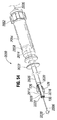
図49〜図53は、人工弁100を送達するおよび植え込むように構成された例示の経心尖送達システムまたは送達ツール2000を示す。送達システム2000は、中心軸を中心として整列され、相互に対して軸方向に摺動可能な一連の同心シャフトおよびシースを備えることが可能である。送達システム2000は、体外での医師操縦用の近位ハンドル部分2002を備え得る一方で、遠位端部分または挿入部分2004は、体内に挿入される。
49-53 show an exemplary transapical delivery system or
送達システム2000は、送達システムの長さにわたり延在する内方シャフト2006を備えることが可能であり、ガイドワイヤ(図示せず)が通され得るルーメン2008を備える。内方シャフト2006は、プッシャシャフト2010のルーメン内に位置決めされ得ると共に、プッシャシャフトの近位端部を越えて近位方向におよびプッシャシャフトの遠位端部を越えて遠位方向に延びる長さを有し得る。送達システム2000は、内方シャフト2006の外方表面とプッシャシャフト2010の内方表面との間に環状空間2012を備えることが可能である。この環状空間は、生理食塩水を用いた洗滌のために、または血液を遠位方向に追いやるのを可能にするために使用され得る。
The
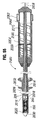
さらに、送達システム2000は、プッシャシャフト2010の少なくとも遠位部分を中心として同心状に位置決めされた内方シース2014を備える。内方シース2014は、送達位置(図55を参照)と後退位置(図50を参照)との間でプッシャシャフト2010に対して軸方向に摺動可能である。送達位置では、内方シース2014の遠位端部分2016は、プッシャシャフト2010の遠位端またはプッシャ先端部2018の遠位に位置決めされる。送達位置では、内方シース2014の遠位端部分2016は、圧縮された人工弁100を収容し得る内方空洞部を形成する。後退位置では(図50を参照)、内方シース2014の遠位端2017は、プッシャ先端部2018の近位に位置決めされるか、またはプッシャ先端部2018と軸方向に整列される。(プッシャシャフト2010に対して近位方向に内方シース2014を後退させるか、または内方シースに対して遠位方向にプッシャシャフトを前進させるかのいずれかによって)、内方シース2014が、送達位置から後退位置に向かい移動するので、プッシャ先端部2018は、内方シースの遠位端部分2016から外に人工弁100を追い出し得る。
In addition, the
図50に示すように、内方シース2014は、内方シースの遠位端2017から近位に延在する1つまたは複数の長手方向に配設されたスロット2028を備える。これらのスロット2028は、本体が内方シース内に圧縮状態で保持される一方で、内方シース2014内に収容された人工弁100の心室固定部126が人工弁の圧縮された本体から径方向に外方に延在するのを可能にし得る。図50に示す実施形態では、2つのスロット2028が、内方シース2014の長手方向中心軸の直径方向に対向する両側に配向されるのが示される。この実施形態は、2つの対向する心室固定部126を備える人工弁100に対応する。他の実施形態では、内方シース2014は、選択された人工弁上の心室固定部の個数および位置に対応する例えば4つのスロットなど、異なる個数のスロット2028を備えることが可能である。図50に示すものなどのいくつかの実施形態では、各スロット2028の近位端部分2020は、スロットの残りの部分よりも大きな角度幅を有する円形開口を備える。
As shown in FIG. 50, the
分離または易壊保持バンド2022が、図50に示すように内方シース2014の遠位端部分2016の周囲に位置決めされ得る。バンド2022は、内方シース2014の遠位端部分2016が、内方シース2014内に収容された圧縮された人工弁100の力から離れて外方に広がらないように保持するのを補助し得る。バンド2022は、内方シース2014のスロット2028の上方に位置する少なくとも1つの切欠部2026を備え得る近位エッジ2024を備える。バンド2022は、易壊材料を含むことが可能であり、十分な軸方向力が切欠部2026に印加されると切欠部位置で破断するまたは分離するように構成され得る。使用時に、バンド2022は、以下でさらに説明されるように内方シース2014から展開されることにより、弁100の心室固定部126の力の下で切欠部2026にて壊れるように構成される。
The separation or
外方シース2036が、内方シース2014の一部分を中心として同心的に位置決めされ、内方シースに対して軸方向に摺動可能である。外方シース2036は、内方シース2014の遠位端部分2016の少なくとも一部分を覆うように位置決めされ得る。図55に示すものなどのかかる覆い位置では、心室固定部は、内方シースと外方シースとの間に収容され得る。外方シース2036は、この覆い位置にある一方で、装填された送達システム2000は、身体を通して左心室6に挿入される。外方シース2036は、シース2014に対して近位方向に後退されることにより、スロット2028を露出させ、展開時に心室固定部126を内方シース2014のスロットを通して外方に跳ねさせることが可能である。代替的には、内方シース2014は、外方シース2036に対して遠位方向に前進されて、スロット2028を露出させることが可能である。
The
図51を参照すると、送達システム2000のハンドル部分2002は、人工弁100を装填、送達、および展開するために、軸方向移動の各範囲に沿って内方シース2014および外方シース2036を前後に摺動させるのを容易にする構成要素を備えることが可能である。外方シースグリップ2052が、外方シース2036の近位端部に装着され得る。医師は、外方シースグリップ2052を把持し、送達システム2000の残りの部分に対して外方シース2036を近位方向および遠位方向に押すまたは引くことが可能である。また、外方シースは、親ねじ(図示せず)上にも取り付けられ得る。送達システム2000のハンドル部分2002は、医師が他方の手をシースを作動させるために使用している際に、医師に送達システム2000を安定的に保持させるためのハンドグリップまたはハンドルを提供するハウジング2054をさらに備えることが可能である。摺動親ねじ2056が、内方シース2014の近位端部分2058に固定(例えば接合、機械式ロック等)され、ハウジング2054内に配置され得る。親ねじ2056は、ハウジング2054に対して回転的に固定されハウジング内で軸方向摺動範囲に拘束され得る。回転可能スリーブ2060が、外方ハウジング2054と内方親ねじ2056との間に同心状に位置決めされ、ハウジング2054から自由に延在して医師が回転可能スリーブ2060を回転させるためのハンドグリップを提供する近位ノブ部分2062を備え得る。回転可能スリーブ2060は、ハウジング2054に対して回転自在であることが可能であるが、ハウジングに対して軸方向には固定され得る。親ねじ2056は、回転可能スリーブ2060上の内方突出リッジ2066と相互作用する外方らせん溝2064を備えることが可能であり、それにより、ノブ2062が親ねじ2056およびハウジング2054に対して回転されると、リッジ2066は親ねじ2056を軸方向に摺動させ、それによりさらに内方シース2014を軸方向に摺動させる。したがって、医師は、ハウジング2054に対してある方向にノブ2062を回転させることにより近位方向に、およびハウジングに対して逆方向にノブを回転させることにより遠位に内方シース2014を移動させ得る。ハウジング2054は、ノブ2062がハウジングに対して回転されると、親ねじ2056および内方シース2014がプッシャシャフト2010およびハウジング2054に対して共に軸方向に摺動するように、プッシャシャフト2010に対して固定され得る。
Referring to FIG. 51, the
図51に示すように、内方シャフト2006は、送達システム2000のハンドル部分2002の全長にわたり通過し、プッシャシャフト2010は、ハンドル部分2002の近位端部キャップ2068にてまたはその付近にて終端し得る。内方シャフト2006の外方表面とプッシャシャフト2010の内方表面との間の環状空間2012(図52および図53を参照)は、ハンドル部分2002の端部キャップ2068の少なくとも1つの洗滌ポート2070に流体連結され得る。洗滌ポート2070は、環状空間2012に流体を注入するおよび/または流体が環状空間から逃げるのを可能にするためのアクセスを提供し得る。
As shown in FIG. 51, the
図49に示すように、ノーズコーン2030が、内方シャフト2006の遠位端部に装着され得る。ノーズコーン2030は、近位ベース2034から遠位尖部2032にかけてテーパ状をなし得る。ベース2034は、外方シース2036の直径と略等しい直径を有し得る。ノーズコーン2030は、送達システム2000の残りの部分に対して内方シャフト2006を近位方向に摺動させることにより近位方向に後退されて、外方シース2036および/または内方シース2014の遠位端部に対接して噛み合うことにより、図55に示すように圧縮された人工弁100をさらに収容し得る。また、ノーズコーン2030は、人工弁100が装填および/または展開されるための空間を提供するために、シースから遠位方向に離れるように移動され得る。身体への送達システム2000を挿通時に、テーパ状ノーズコーン2030は、体内に送達システム2000の挿入部分2004を案内するためのウェッジとして機能することが可能であり、送達システムが身体を通して前進される際の周囲組織に対する外傷を最小限に抑えるための非外傷性先端部を提供する。
As shown in FIG. 49, the
送達システム2000内に人工弁100を装填するためには、図54に示すように、ノーズコーン2030は、シースから遠位方向に離れるように移動されなければならず、内方シース2014は、送達位置まで遠位方向に前進されなければならない(保持バンド2022を伴わない)。外方シース2036は、内方シース2014のスロット2028を露出させるように後退され得る。次いで、人工弁100は、ノーズコーン2030と内方シース2014との間に、および内方シャフト2006の周囲に位置決めされる。次いで、人工弁100は、圧縮状態に圧縮され、図56に示すように人工弁の近位端部または下方端部がプッシャ先端部に隣接するかまたは接触するように、内方シース2014内へと摺動する。装填コーン機構または均等の機構が、内方シース2014に弁100を挿入するために使用され得る。図25に示すものなどのプッシャ部材204を備える人工弁100の実施形態では、プッシャ部材204の底端部206は、図56に示すようにプッシャ先端部2018に接触することが可能である。心室固定部126は、図54に示すように各スロット2028の円形近位端部分2020を通して外方に延出することが可能であり得る。各スロットの近位端部分2020は、心室固定部126の2つの端部部分がスロット内で横並びに位置するのを可能にするのに十分な角度幅を有することが可能であり、これにより心室固定部の中間部分は、弁尖10、12の背後に植え込むのに望ましい形状を取ることが可能となる。分離保持バンド2022は、図50に示すようにバンド2022の各切欠部2026が各スロットの上方に位置するように、内方シース2014の遠位端部分の周囲に配置され得る。次いで、外方シース2036は、図55に示すようにスロット2028を覆うように遠位に前進され、それにより心室固定部126を圧迫し、外方シース2036内に心室固定部を拘束する。代替的には、人工弁は、内方シース2014に挿入され得る一方で、外方シース2036は、心室固定部126がスロット内に位置決めされるがスロットから延出し得ないように、スロット2028を覆っている。また、心室固定部126は、内方シース2014の外方表面と外方シース2036の内方表面との間で拘束され得る。いずれの場合でも、心室固定部126は、外方シース2036が後退されると、径方向に外方に跳ね出し自在になる。人工弁100が内方シース2014内に位置した後に、内方シャフト2006は、図55に示すように内方シース2014および/または外方シース2036の遠位端部に対してノーズコーン2030を引くように引き戻され得る。内方シャフト2006内に人工弁100が位置し、ノーズコーン2030が後退され、外方シース2036が心室固定部126を拘束した状態で、送達システム2000は装填構成となり、体内への挿入が可能な状態となる。
In order to load the
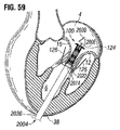
図55に示す装填構成では、装填送達システム2000は、ノーズコーン2030から先に心尖38を通して左心室6に挿入され、展開のために僧帽弁領域付近に位置決めされ得る。初めに、挿入器シース(図示せず)が、心臓の切開部に挿通されて、心臓内に送達システム2000を導入するためのポートを形成し得る。さらに、送達システム2000は、送達システム2000に先立ち心臓内に前進される従来のガイドワイヤ(図示せず)上で前進され得る。次いで、図56および図57に示すように、グリップ2052が、送達システムの残りの部分に対して近位方向に移動されて、内方シース2014に対して外方シース2036を後退させ、心室固定部126が内方シース2014から離れるように外方に跳ねるのを可能にし得ることにより、心室固定部は、スロット2028の円形近位端部分2020を通り延在する。望ましくは、送達システムは、各心室固定部126が天然僧帽弁尖10、12の一方に付着する腱索16のセット間に位置決めされるように、回転的に配向される。次に、図58に示すように、送達システム2000は、ノーズコーン2030が天然僧帽弁口に進入し、突出する心室固定部126が各弁尖10、12と心室壁20との間で移動するように心房に前進され得る。次いで、医師は、送達システム2000のハウジング2054を安定的に保持しつつ、ハウジングに対して回転可能スリーブ2060のノブ2062を回転させて内方シース2014を近位方向に後退させることが可能となる。プッシャ先端部2018は、内方シース2014が後退される際に定置状態に留まり、それにより、露出され内方シース2014から展開される際に圧縮された人工弁100を同一の軸方向位置に残す。代替的には、内方シース2014は、プッシャ先端部2060が遠位方向に移動されて内方シース2014から弁100を押し出す際に、定置状態に保持され得る。内方シース2014が、プッシャ先端部2018に対して後退されつつある間に、プッシャ先端部は、人工弁100の近位表面または最下表面に対して遠位方向に軸方向力を印加し得る。プッシャ部材204を有する人工弁の実施形態では、プッシャ部材204は、本体122へと直接的にこの軸方向力を送り、プッシャ先端部2018と心室固定部126との間の直接的な接触を防止して心室固定部に対する損傷リスクを低減させ得る。
In the loading configuration shown in FIG. 55, the
内方シース2014が人工弁100に対して後退される場合に、下方に折り畳まれた心房封止部材124を備える人工弁の遠位部分または上方部分は、初めに露出される。図59および図60を参照すると、内方シース2014が、人工弁100の心房封止部材124の外方リムを越えて後退された場合に、心房封止部材は、本体122から離れるように径方向に外方に跳ねて、本体の遠位端部を中心として枢動し得る。
When the
内方シース2014が人工弁100に対して後退されることにより、スロット2028の円形近位端部分2020を通過する心室固定部126の端部部分は、図59および図60に示されるように保持バンド2022に向かってスロット2028の、より幅狭の遠位部分を通して追いやられる。心室固定部の端部部分は、初めにスロットの、より幅広の近位端部分2020内で横並びに位置する。スロット2028の、より幅狭の部分内に追いやられると、各心室固定部126の2つの端部部分は、横並びとは対照的に、径方向に重畳するかまたは一方が他方の上に配向され得る。他の実施形態では、スロット2028は、心室固定部126の2つの端部部分がスロット2028の周囲で横並びに移動し得るように、より幅広であることが可能である。心室固定部126が、スロット2028の遠位端部に向かって移動することにより、心室固定部は、図60に示すように保持バンド2022の切欠部2026に接触することが可能となり、バンド2022を切断し得るか、または図61に示すように切欠位置にて他の方法でバンドを引き裂かせ得るまたは分離させ得る。内方シース2014が、人工弁100の近位端部または下方端部を越えて後退されると、人工弁の圧縮された本体は、図61に示すように拡張状態へと弾性的に自動拡張し得る。人工弁が拡張すると、心室固定部126と本体122の外方表面との間の間隙は縮小して、図23および図62に示すように心室固定部126と本体122との間で弁尖10、12を捕獲する。人工弁100の本体122の拡張により、天然弁尖10、12は開かされて、天然僧帽弁2は開位置に保持され得る。次いで、人工弁100は、天然僧帽弁2の機能を置換することが可能となる。人工弁100が拡張された後に、送達システムの内方シャフト2006は後退されて、人工弁を通してノーズコーン2030を後退させることが可能となり、送達システム2000全体が体外へと引き出され得る。
By retracting the
いくつかの実施形態では、送達システム2000は、ガイドワイヤ(図示せず)を使用して体内および/または体外に案内され得る。ガイドワイヤは、心臓内におよび天然僧帽弁口を通して挿入され、次いでガイドワイヤの近位端部は、内方シャフト2006のルーメン2008を通され得る。次いで、送達システム2000は、ガイドワイヤを使用して身体に挿通されて、送達システムの経路を配向し得る。
In some embodiments, the
心房アプローチ
代替的には、人工弁100は、左心房4から天然僧帽弁領域に送達され得る。図63〜図67を参照すると、僧帽弁領域の心房側から人工弁を送達するための1つのアプローチは、送達カテーテル2100を使用する。初めに、人工弁100は、拡張状態から径方向圧縮状態に圧縮され、図63に示すように送達カテーテル2100の遠位端部分にて一次シース2102内に、および任意にはさらに二次シース内に装填される。送達カテーテル2100は、身体をとして左心房4内に人工弁100を案内するために使用される。人工弁100は、人工弁100の流出端部112(心室固定部126を支持する端部)がシースの遠位端部に最も近く、したがって初めに左心房4に進入し、人工弁の流入端部110(心房封止部材124)が最後に進入するように、シース2102内に配向される。次いで、シース2102は、様々な様式で左心房4に挿入され得る。一例が、図66に示す経心房アプローチであり、別の例が、図67に示す経中隔アプローチである。送達カテーテル2100が、例えば図67に示すような患者の血管系を経由して心臓にアクセスするために使用される場合には、カテーテル2100は、可撓性の操縦可能なカテーテルを備えることが可能である。
Atrial approach Alternatively, the
一次シース2102の遠位端部2104は、左心房4内に位置すると、シースから心室固定部を展開する前に心室固定部126が僧帽弁尖10、12を越えて位置決めされるように、僧帽弁輪8を越えて移動され得る。
The
次いで、人工弁100は、シース2102内に位置決めされる剛性プッシャシャフト2106(図64を参照)を使用して一次シース2102の遠位端部2104から部分的に押し出され、シースに対して軸方向に摺動し得る。シース2102が、プッシャシャフト2106および人工弁100に対して近位方向に後退されると、プッシャシャフト2106は、図64に示すようにシース2102から遠位方向に人工弁を押し出す。代替的には、プッシャシャフト2106は、遠位方向に移動され得る一方で、シース2102は、定位置に保持され、それによりシースから人工弁100を遠位方向に押し出す。
The
一次シース2102が、僧帽弁輪8を越えて弁尖10、12の下方端部を通過して挿入されると、人工弁100は、図64に示すように部分的に押し出されて心室固定部126を解放し得る。解放された心室固定部126は、シース2102から解放された際に外方に跳ね得る。任意には、次いでシース2102は、図65に示すように心室固定部のみが見えるように本体122の露出部分上を摺動して戻され得る。このステップを達成するために、フレームの心房端部は、プッシャシャフトがシース2102内に人工弁を後退させ得るように、プッシャシャフト2106に人工弁100を解除可能に装着するための機械式ロック特徴部などの特徴部(図示せず)を備えることが可能である。次いで、シース2102および人工弁100は、図66〜図68に示すように外方に突出する心室固定部126が各弁尖10、12と心室壁20との間で移動するように、近位方向に心房に後退される。図44および図45に示すものなどの他の実施形態では、心室固定部は、心室固定部がシース2102から解放された場合に、上方に弾性的にたわむか、または各弁尖10、12の周囲で曲がることが可能である。
When the
任意には、送達カテーテル2100は、外方シース2102内に二次シース(図示せず)をさらに備えることも可能であり、プッシャシャフト2106、心房封止部材124、およびフレームの本体122を収容することが可能であるが、固定部126を収容することは不可能である。図63に示す位置では、二次シースの遠位端部は、固定部126と本体122との間に位置決めされ得る。外方一次シース2102が図64におけるように引き戻されることにより、二次シースは、固定部126が解放されて外方に延出する一方で、フレームの本体122を圧縮する位置に留まり得る。二次シースが本体122を覆い圧縮する状態に留まることにより、図65におけるように一次シース2102で本体を復元させる必要はない。代わりに、人工弁100は、二次シースおよびプッシャシャフトを近位方向に一斉に移動させることによって近位方向に移動される。次いで、二次シースから人工弁100を押し出すために、二次シースは、プッシャシャフト2106に対して近位方向に後退される。
Optionally, the
心室固定部126が弁尖10、12の背後に位置決めされ、人工弁100の残りの部分が一次シース2102から押し出された後に、人工弁100は、図62および図69に示すようにその機能サイズへと拡張し、それにより心室固定部126と本体122との間で弁尖10、12を捕獲することが可能となる。人工弁100が植え込まれると、送達カテーテル2100は体外に後退され得る。
After the
代替的な人工弁実施形態では、フレームの本体および心房封止部材は、塑性的に拡張可能であることが可能であり、人工弁が所望の位置に位置決めされるとバルーンカテーテル(図示せず)のバルーンにより拡張され得る。かかる一実施形態の心室固定部は、展開時に心室固定部と本体との間に弁尖10、12を位置決めするのを支援するのに望ましい弾性量を示し得る。人工弁が完全に拡張されると、バルーンは、拡張された人工弁を通り体外へと引き出され得る。
In an alternative prosthetic valve embodiment, the body of the frame and the atrial sealing member can be plastically expandable and a balloon catheter (not shown) when the prosthetic valve is positioned in the desired position. Can be expanded by a balloon. The ventricular fixation portion of such one embodiment may exhibit a desirable amount of elasticity to assist in positioning the
僧帽弁逆流の軽減
僧帽弁逆流(MR)は、天然僧帽弁が適切に閉じることができず、血液が心臓収縮の収縮期に左心室から左心房に流入する場合に発生する。MRは、心臓弁膜症の最も一般的な形態である。MRは、弁尖逸脱、機能不全の乳頭筋、および/または左室の拡張の結果として生じる僧帽弁輪の伸張などの種々の原因を有する。弁尖の中心部分におけるMRは、中心ジェットMRと呼ばれ、弁尖のある交連部により近いMRは、偏心ジェットMRと呼ばれ得る。
Mitigation of mitral regurgitation Mitral regurgitation (MR) occurs when the natural mitral valve fails to close properly and blood flows from the left ventricle into the left atrium during systole of cardiac contraction. MR is the most common form of valvular heart disease. MRs have a variety of causes, including leaflet deviation, dysfunctional papillary muscles, and / or extension of the mitral annulus resulting from dilation of the left ventricle. The MR at the central portion of the valve leaflet may be referred to as the central jet MR, and the MR closer to the commissure with the valve leaflet may be referred to as the eccentric jet MR.
MRを治療する別の方法は、天然僧帽弁を完全置換するのではなく、逆流弁口面積を縮小するプロテーゼスペーサを弁尖間に位置決めすることにより、僧帽弁が逆流を殆どまたは全く伴わずに機能するのを可能にすると共に、天然弁および左心室機能へのならびに周囲組織への影響を最小限に抑えることによるものである。MRの治療に関するさらなる情報は、特許文献5および特許文献6に見ることができ、これらは共に参照により本明細書に組み込まれる。
Another way to treat MR is to position the prosthesis spacer between the leaflets to reduce the area of the regurgitation valve opening, rather than completely replacing the natural mitral valve, so that the mitral valve is accompanied by little or no regurgitation. This is by allowing it to function without, while minimizing its impact on the natural valve and left ventricular function as well as on surrounding tissues. Further information regarding the treatment of MR can be found in
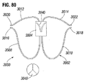
図71は、スペーサまたは他の物体が本明細書で説明される固定コンセプトを利用して弁尖間で懸吊され得るまたは「遊動」し得るための、例示のプロテーゼスペーサ実施形態3000を示す。プロテーゼスペーサ3000は、フレーム3002およびスペーサ体3004を備えることが可能である。スペーサ体3004は、ポリウレタン、発泡材、および/または他の適切な材料を含むことが可能であり、任意にはテフロン(登録商標)および/または他の適切な材料で被覆され得る。スペーサ体3004は、前方弁尖10と後方弁尖12との間の三日月形状連接部に形状合致する三日月形状を備え得る(図4Aおよび図4Bを参照)か、またはスペーサ体は、楕円形、円形、砂時計形等の他の適切な形状を備えることが可能である。スペーサ体3004の形状および天然構造体に対するスペーサ体の位置に応じて、プロテーゼスペーサ3000の実施形態は、中心ジェットMR、偏心ジェットMR、またはその両方の治療を補助し得る。
FIG. 71 shows an exemplary
さらに、スペーサ体3004は、最小横断断面積およびテーパ状エッジを備えることが可能である。この形状は、左心房から左心室へと僧帽弁を通り流れる血液から拡張期力を低下させ得る。また、この形状は、天然弁がスペーサ体の周囲で閉じられた場合にスペーサ体3004に対する収縮期力を低下させ、天然弁尖および腱に対して収縮期力の、より多くの部分を必然的に印加することが可能である。したがって、スペーサ体3004の形状は、固定部係合位置の天然弁組織に伝達される力を低下させることが可能となり、これは、係合位置における穿孔および浸食と、弁尖を支持する天然腱の破断との可能性を低下させ得る。さらに、プロテーゼスペーサ3000の最小全体サイズにより、送達システムの所要断面サイズを縮小することが可能となり、それにより身体および心臓のより小さな血管系切開部および/または侵襲切開部を通した送達を許容する。
Further, the
フレーム3002は、ニチノールなどの強力な可撓性材料から作製され得る。図71に示すように、フレーム3002は、フレーム体3006、前方心室固定部3008、後方心室固定部3010、前方心房固定部3012、および後方心房固定部3014を備えることが可能である。フレーム体3006は、スペーサ体3004を通り延在する略長手方向のコラムを備えることが可能である。次に、フレーム体3006の様々な実施形態を詳細に説明する。
The
フレーム3002は、フレーム体3006からスペーサ体3004を通り側方に延在する1つまたは複数のスペーサ拡張器3024をさらに備えることが可能である。拡張器3024は、フレーム体から離れるように弾性的に拡張し、展開時にスペーサ体3004の拡張を支援することが可能である。いくつかの実施形態では、スペーサ拡張器3024は、フレーム体から径方向に離れるように曲げられる図71に示すような円筒状フレーム体3006の矩形切欠部分であることが可能である。
The
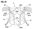
前方心室固定部3008は、フレーム体3006の心室端部から前方弁尖10のA2エッジの周囲を延在し、僧帽弁輪8の心室表面上および/または前方弁尖の環状連結部分上の位置へと弁尖の背後で上方に延在するように構成され、一方で前方心房固定部3012は、前方心室固定部3008とは逆にフレーム体3006の心房端部から僧帽弁輪8の心房表面上の位置まで径方向に延在するように構成される。同様に、後方心室固定部3010は、フレーム体3006の心室端部から後方弁尖12のP2エッジの周囲を延在し、僧帽弁輪8の心室表面上および/または後方弁尖の環状連結部分上の位置へと弁尖の背後で上方に延在するように構成され、一方で後方心房固定部3014は、後方心室固定部3010とは逆にフレーム体3006の心房端部から僧帽弁輪8の心房表面上の位置まで径方向に延在するように構成される。
The anterior
心室固定部3008、3010および心房固定部3012、3014は、僧帽弁輪8および/または弁尖10、12の環状連結部分を圧迫することにより心房方向および心室方向の両方への移動を防ぐようにプロテーゼスペーサ3000を保持するように構成され得る、幅広掛合部分3016、3018、3020、および3022をそれぞれ備える。幅広掛合部分は、荷重を分散させ、係合位置の穿孔または浸食などの損傷を天然組織に与える可能性を低下させるために、固定部と天然組織との間により大きな接触面積を与え得る。図示する構成における心室固定部3008、3010は、天然弁尖10、12の周囲でループし、スペーサ体3004の外方表面に対して天然弁尖を圧迫しないことにより、天然弁尖はスペーサ体3004の周囲で自然に開閉することが可能となる。
The
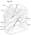
図74に示すように、僧帽弁輪8は、前後寸法が弁輪の最小寸法と見なされるような、略腎臓形状である。プロテーゼスペーサ3000は、天然僧帽弁2の前方領域および後方領域にて固定し得るため、後方スペーサは、弁輪8の最小寸法にしたがってサイズ設定され得る。僧帽弁輪8の小さい方のサイズのエコーおよびCT測定は、プロテーゼスペーサ3000をサイズ設定する例示の方法である。
As shown in FIG. 74, the
図75〜図79は、心臓の天然僧帽弁領域にプロテーゼスペーサ3000を送達するための例示の方法を示す。プロテーゼスペーサ3000は、外方シース3030および内方トルクシャフト3032を備える送達システムを使用して心臓内に送達され得る。プロテーゼスペーサ3000は、圧縮され、心房固定部3012、3014が先に装填される状態で外方シース3030の遠位端部内に装填される。図75に示すように、心房固定部は、近位方向に弾性的に延在され、プロテーゼスペーサ3000が外方シース3030のルーメン内に嵌るのに十分な幅狭断面積を有するように、心室固定部3008、3010は弾性的に遠位に延伸する。外方シース3030内で、プロテーゼスペーサ3000は、フレーム体3006の心房端部がトルクシャフト3032の遠位端部に当接し、心房固定部3012、3014がトルクシャフトと外方シャフトの内方壁部との間に位置し、圧縮されたスペーサ3004が外方シースの内方壁部に当接し、心室固定部3008、3010の遠位端部が外方シースの遠位開口に隣接するように位置決めされる。トルクシャフト3032は、フレーム体3006の近位端部にてなど、プロテーゼスペーサ3000の心房端部に解除可能に結合され得る。
75-79 show exemplary methods for delivering the
装填されると、送達システムは、心房中隔30を経由してなど左心房4内に導入され、外方シース3030の遠位端部は、図75に示すように天然僧帽弁2を通り左心室6内に送られ得る。
Once loaded, the delivery system is introduced into the
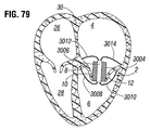
次に、外方シース3030が、トルクシャフト3032に対して後退されて、外方シースの遠位開口から心室固定部3008、3010を押し出し得る。この時点で、トルクシャフト3032は、天然弁2のA2/P2面に心室固定部を整列させる必要に応じて、外方シース3030内でプロテーゼスペーサ3000を回転させるために回転され得る(または任意にはトルクシャフトおよび外方シースが共に回転され得る)。トルクシャフト3032とプロテーゼスペーサ3000との間の解除可能な装着は、必要に応じてプロテーゼを回転させるためにトルクシャフトからプロテーゼにトルクを伝達させるのに十分なものとすることが可能である。心室固定部3008、3010は、外方シース3030から徐々に押し出されることにより、相互から離れるようにおよび弁尖のA2/P2領域の周囲で巻き始めるように事前形成され得る。この巻き動作は、心室壁との係合を回避するために望ましいものとなり得る。外方シース3030が、図76に示すようにフレーム体3006の心室端部に後退されると、心室固定部3008、3010は、外方シースから完全に押し出され、弁尖の背後に位置決めされる。次いで、心室固定部の係合部分3016、3018が僧帽弁輪8の心室側および/または弁尖10、12の弁輪連結部分に当接するまで、送達システムおよびプロテーゼの全体が近位方向に移動され得る。
The
次に、外方シース3030は、図77に示すように外方シースの遠位端部がフレーム体3006の心房端部と同一高さになるように、トルクシャフト3032に対してさらに後退され得るが、これにより、圧縮されたスペーサ拡張器3024および圧縮されたスペーサ体または他の物体3004は、完全に拡張された機能状態へと径方向に外方に弾性的に自動拡張することが可能となる。スペーサ体3004は、弁輪の小さな方の寸法に対して垂直な、または交連部36に向かう方向に大部分において拡張する点に留意されたい(図74を参照)。いくつかの実施形態では、スペーサ体3004は、圧縮状態から拡張状態に開くまたは広がることが可能であり、いくつかの実施形態では、スペーサ体は、生理食塩水でまたは時間の経過と共に硬化するエポキシでなど膨張され得る。
The
スペーサ体が、図77に示すように弁内で拡張されると、スペーサの血行動態評価が実施されて、MRの低減におけるプロテーゼスペーサ3000の効果が評価され得る。評価の結果に応じて、展開が継続され得るか、またはプロテーゼスペーサ3000が復元され得る、後退され得る、および/または展開のために再位置決めされ得る。
When the spacer body is expanded in the valve as shown in FIG. 77, a hemodynamic evaluation of the spacer can be performed to evaluate the effect of the
外方シース3030は、図77に示す位置から、スペーサ体3004上を前進されて戻され(トルクシャフト3032に対して外方シース3030を前進させることにより)、それにより図76に示すようにスペーサ体を再圧縮することが可能となる。いくつかの実施形態では、心室固定部は、復元可能ではないが、いくつかの実施形態では、心室固定部は、再度直線状になされ復元されるのに十分な柔軟性を有することが可能であり、その場合には、次いで送達プロセス全体が逆順に行われ再開され得る。図76に示す位置から、送達システムは再位置決めされ、スペーサ体3004は再展開および再評価され得る。
The
心室固定部3008、3010およびスペーサ体3004が許容し得るように展開されると、外方シース3030は、人工スペーサ3000およびトルクシャフト3032に対してさらに後退されて、図78に示すように外方シースから心房固定部3012、3014を押し出すことが可能となる。心房固定部は、完全に押し出されると、図78に示す最終展開位置へと弾性的に巻き、それらの係合部分3020、3022は、心室固定部の係合部分3016、3018のそれぞれとは逆に弁輪8の心房側および/または弁尖10、12の弁輪連結部分に対して押圧され、それによりA2領域およびP2領域にて弁尖の弁輪および/または弁輪連結部分を圧迫して天然僧帽弁領域2内にプロテーゼスペーサ3000を保持する。
When the
心房固定部3012、3014が展開されると、トルクシャフト3032は、フレーム体3006の心房端部から解放され得る。次いで、送達システムは、体外へと後退されて、図79に示すようにプロテーゼスペーサ3000を植え込まれた状態に残す。
When the
いくつかの実施形態では、スペーサ体3004は、図80および図82に示す実施形態などの弁構造体3040を備えることが可能である。弁構造体3040は、天然僧帽弁2と組み合わせて機能することにより、左心房4と左心室6との間の血流を調整することが可能である。例えば、弁構造体3040は、天然弁尖が弁構造体の外部の周囲で閉じることにより、一部の血液が弁構造体を通り流れる一方で、他の血液が弁構造体の外部と天然弁尖との間を流れるように、天然弁尖間に位置決めされ得る。弁構造体3040は、弁構造体104を参照として本明細書で説明され図5〜図7に示されるものなどの3弁尖構成を備えることが可能である。
In some embodiments, the
いくつかの実施形態では、フレーム体3006は、円筒を備えることが可能であり、この円筒は、図71〜図74におけるような固体壁チューブ、図82におけるようなメッシュ状ワイヤ格子3046、または他の円筒状構成体を任意に備えることが可能である。図71〜図75を参照すると、フレーム体3006および任意には固定部の1つまたは複数は、ニチノールなどの固体壁チューブから形成されることが可能であり、心房固定部は、チューブの一部分からレーザ切断によってなど形成され、心室固定部は、チューブの第2の部分から形成され、フレーム体は、第1の部分と第2の部分との間のチューブの部分から形成される。次いで、固定部は、熱処理によってなど所望の植え込み構成へと形成され得る。かかる実施形態では、固定部およびフレーム体は、単体構造またはモノリシック構造とすることが可能である。
In some embodiments, the
他の実施形態では、フレーム体3006は、図83に示すようなばね状らせん巻きワイヤコラム3050を備えることが可能である。かかる巻きコラム3050は、円形または矩形の断面を有するワイヤから作製することが可能であり、送達のために長手方向コラム剛性を維持しつつ天然弁構造体に形状合致するための側方可撓性を与えるニチノールなどの弾性的に可撓性のある材料を含むことが可能である。いくつかのこれらの実施形態では、フレーム体3006は、心房固定部3012、3014を形成するように延在する4つの心房端部と、4つの心室固定部3008、3010を形成するように延在する4つの心室端部とを有する4つのワイヤの4らせんコイルを備えることが可能である。
In another embodiment, the
他の実施形態では、フレーム体3006は、複数の長手方向部材(図示せず)を備えることが可能である。かかる一例では、フレーム体3006は、4つの長手方向部材を、すなわち前方固定部3012、3014を形成するように延在する2つの長手方向部材と、後方固定部3008、3010から延在する2つの長手方向部材とを備えることが可能である。
In another embodiment, the
他の実施形態では、フレーム体3006は、コラム強度を維持しつつ側方可撓性を実現することも可能な、図81に示すようなフレーム体の長手方向に沿ったジグザグカットパターン3050を備えることが可能である。
In another embodiment, the
いくつかの実施形態では、プロテーゼスペーサ3000は、追加の固定部を有することが可能である。いくつかの実施形態では(図示せず)、プロテーゼスペーサ3000は、3つの対の固定部、すなわち上述の後方固定部3010および3014などの後方弁尖12を中心とする1つの対の固定部と、天然弁尖10、12間の各交連部36の1つの対の固定部とを有することが可能である。これらの交連部固定部対は、心室固定部および心房固定部を同様に備えることが可能であり、天然弁輪8を同様に圧迫することが可能である。また、他の実施形態では、前方固定部3008および3012は、4つの対の固定部として備えられ得る。他の実施形態は、これらの4つの対の固定部および/または追加の固定部の他の組合せを備えることが可能である。
In some embodiments, the
逆流オリフィスエリアを充填し、血液が左心房に流れるのを阻止することに加えて、プロテーゼスペーサ3000は、腱索に張力を付加することによって左心室のさらなる拡大を防止し、僧帽弁輪のさらなる拡張を防止することも可能である。
In addition to filling the regurgitation orifice area and preventing blood from flowing into the left atrium, the
僧帽弁交連部下方の固定
人工弁およびプロテーゼスペーサの両方を備える心室固定部を備えるプロテーゼデバイスのいくつかの実施形態は、心室固定部が天然僧帽弁尖10、12のA2/P2領域の背後で固定する代わりにまたはそれに加えて、天然僧帽弁2の交連部36の下方で固定するように構成され得る。図84〜図87は、天然僧帽弁2の2つの交連部36の下方で固定する心室固定部を備える例示のプロテーゼデバイス実施形態と、関連する送達方法とを示す。これらの交連部固定コンセプトは、主に人工弁と共に使用することを目的とされるが、プロテーゼスペーサを含む他のプロテーゼデバイスと共に使用することも可能である。
Fixation below the mitral valve commissure In some embodiments of a prosthesis device with a ventricular fixation with both a prosthetic valve and a prosthesis spacer, the ventricular fixation is in the A2 / P2 region of the natural
図3、図4、および図88に示すように、交連部36は、前方弁尖10および後方弁尖12が接合される天然僧帽弁2のエリアである。図88に示すように、各交連部36に隣接する天然僧帽弁輪8の部分39は、弁尖の中間部分A2/P2に隣接する僧帽弁輪8の部分よりも比較的厚いおよび/または強力であることが可能であり、これによりプロテーゼ装置を固定するための剛性の安定的な位置が提供される。これらの弁輪領域39は、天然弁尖組織よりも大きな荷重を受けることが可能であり、天然凹状表面または腔部を形成することが可能な、強靭な線維組織を備えることが可能である。
As shown in FIGS. 3, 4, and 88, the
図84および図85は、腔部39の中の1つに心室固定部4002を位置決めすることによって天然僧帽弁領域2に植え込まれつつある例示のプロテーゼ装置4000を示す。プロテーゼ装置4000は、MRを低減させるための弁尖構造体を有する人工弁またはスペーサ体3004を有するスペーサデバイスであることが可能である。腱索16は、交連部36に隣接して弁尖10、12に付着し、この交連部36は、腱の背後の腔部39への心室固定部の位置決めの際に障害物となり得る。しかしながら、固定部4002などの固定部を腱16の周囲に送達して、腔部39に到達することが可能である。これらの天然腔部39内の腱16の背後に心室固定部の係合部分4004などの係合部分を位置決めすることは、天然僧帽弁領域2にプロテーゼ装置を保持するのに望ましいものとなり得る。しかし、天然腱16との絡み合いおよび/または天然腱16への損傷を回避するためには、図84に示すように初めに後内側乳頭筋22からの腱16と前外側乳頭筋24からの腱16との間のA2/P2領域の弁尖10、12の背後に垂直方向に固定部の係合部分を案内し、次いで図85に示すように交連腔部39に向かって腱16の背後の周囲で水平方向に固定部の係合部分を移動または回転させることが望ましいものとなり得る。
84 and 85 show an
いくつかのかかる方法では、心室固定部は、初めに弁尖のA2/P2領域の背後で展開され、次いでプロテーゼ装置全体が、図84および図85に示すように回転または旋回されて腔部39に向かって水平方向に固定部の係合部分を移動させる。例えば、前方弁尖10の背後に展開される第1の固定部は、腔部39の中の1つに向かって移動することが可能であり、後方弁尖12の背後に展開される第2の固定部は、他の腔部39に向かって移動することが可能である。この方法は、プロテーゼ全体が回転されて天然組織に固定部を係合させるため、「スクリュー方法」とも呼ばれ得る。
In some such methods, the ventricular fixation is first deployed behind the A2 / P2 region of the valve leaflet, and then the entire prosthesis device is rotated or swiveled as shown in FIGS. 84 and 85 to form the
図84および図85に示すように、屈曲形状、湾曲形状、フック形状、または略「L字」形状の固定部4002を備えるプロテーゼ装置4000が、スクリュー方法と共に使用され得る。「L字」形状固定部4002は、装置4000の本体から垂直方向に上方に延在するレッグ部分4006と、ニー部分4008と、ニー部分から水平方向に延在し係合部分4004にて終端するフット部分4010とを備えることが可能である。これらの実施形態のいくつかでは、「L字」形状固定部4002は、ワイヤが1対のレッグ部分4006、1対のニー部分4008、および1対のフット部分4010を形成するように、2つの位置で装置4000の本体に装着するループ状ワイヤを備えることが可能である。他の実施形態では、固定部4002は、図84に示す直角形状ではなくより円弧状の形状などの他の同様の形状を有することが可能である。心臓内へと送達時には、フット部分4010は、装置4000の本体の外方表面の周囲で巻かれるまたは囲むことが可能である。
As shown in FIGS. 84 and 85, a
図84に示すように、腱との絡み合いを伴わずに弁尖10の背後に垂直方向にフット部分4010を移動させるために、レッグ部分4006は、所望の送達のために、腔部39の対向側の腱のより付近に、A2領域から若干中心を外れて位置決めされ得る。図84に示すように、レッグ部分4006は、フット部分4010が腱16同士の間を通過し得るように右に位置決めされる。
As shown in FIG. 84, in order to move the
フット部分4010が腱16から離れ、弁尖の背後に位置決めされた後に、装置4000は、回転されて、図85に示すように腔部39内に水平方向に係合部分4004を移動させ得る。図85では、レッグ部分4006は、腱との干渉を回避するために腱16同士の間のA2/P2領域に位置決めされて終わり得る点に留意されたい。
After the
図84および図85は、単体固定部4002を示す一方で、前方固定部および後方固定部は共に、各腔部39に各一方が固定された状態で、天然弁2の両側に対称的に分配され得る。2つの固定部4002のフット4010は、図85に示す旋回運動により2つの腔部39へと同時にそれらが移動されるように、逆方向に向くことが可能である。2つの固定部実施形態の送達時に、2つのフット部分4010は、2つのフット部分4010が他方に重畳するように、装置4000の本体の外方表面の周囲を囲むことが可能である。
84 and 85 show the
同様の実施形態で、固定部4002は、逆方向に延在する2つのフット部分4010を有するパドル形状部(例えば図37を参照)を備えることが可能である。腱同士の間の移動がより困難になるが、これらのパドル形状固定部は、装置4000がいずれかの方向に回転されて、腔部39でフット部分4010の一方に係合することを可能にし得る。いくつかの実施形態では、パドル形状固定部は、一方のフット部分4010が1つの腔部39に位置決めされ得る一方で、他方のフット部分が他の腔部に位置決めされるように十分な幅の広さを有し得る。
In a similar embodiment, the
各固定部4002が、2つの位置で装置4000の本体に装着するため、これらの固定部は、本体が圧縮される場合に装置の本体から離れて広がり、図11〜図22を参照として上記で詳細に説明したように弁尖を受けるための間隙を形成することが可能である。いくつかの実施形態では、固定部は、本体が圧縮された場合に本体から分離することが可能であり、弁尖が装置の固定部と本体との間で挟まれるまたは圧迫されることがないように本体から離間された状態に留まるか、または拡張時に弁尖に係合するように本体に対して閉じるかのいずれかが可能である。いくつかの実施形態では、本体は、本体が拡張した場合に対向し合う固定部のフット部分4010間の距離を維持しつつ間隙を縮小させるように、固定部に向かって移動することが可能である。
Since each fixing
図86および図87は、腔部39に心室固定部5002を位置決めすることにより天然僧帽弁領域2に植え込まれつつある別の例示のプロテーゼ装置5000と、それを実施するための対応する方法とを示す。この実施形態では、装置5000は、1対の「L字」形状固定部5002を各側に備えることが可能であり(図86および図87では1対のみが視認可能である)、各対は、腔部39の中の1つに位置決めするための一方の固定部と、他の腔部に位置決めするための別の固定部とを備える。各固定部は、装置5000の本体からニー部分5008に垂直方向に延在するレッグ部分5006と、ニー部分5008から係合部分5004に水平方向に延在するフット部分5010とを備えることが可能である。他の実施形態では、固定部5002は、図86に示す角度をつけられた形状ではなく、より円弧状の形状などの他の同様の形状を有することが可能である。
86 and 87 show another
各対の固定部5002は、図86に示すように弁尖の背後への送達のために事前撓曲状態にありおよび引き留め位置に拘束され、次いで解放されて弾性的に跳ね外れて図87に示すように2つの腔部39に向かって逆方向に係合部分5004を移動させることが可能となるように、ニチノールなどの弾性的に可撓性のある材料を含むことが可能である。解除可能機械式ロック機構などの任意の適切な拘束および解放機構が使用され得る。解放されると、1つの前方固定部および1つの後方固定部が、逆方向から1つの腔部39に位置決めされ、第2の前方固定部および第2の後方固定部が、逆方向から他の腔部に位置決めされ得る。いくつかの実施形態は、解放時に対向する腔部39に向かって逆方向に移動する装置5000の各側の1つのみの固定部を備えることが可能である。
Each pair of
各対の固定部5002が、初めに図86に示すように共に拘束されるため、各対の固定部は、装置5000の本体に2つの装着点を有する単一の固定部のように機能し得る。したがって、固定部対は、本体が圧縮された場合に本体から分離するまたは離れて拡張することが可能であり、弁尖が装置の固定部と本体との間で挟まれるまたは圧迫されることがないように本体から離間された状態に留まるか、または拡張時に弁尖に係合するように本体に対して閉じるかのいずれかが可能である。いくつかの実施形態は、本体は、本体の拡張時に対向する固定部対のフット部分5010間の距離を維持しつつ、固定部対に向かって移動して間隙を縮小させることが可能である。
Since each pair of
図84〜図87に示す実施形態では、プロテーゼ装置4000または5000は、心室固定部4002、5002が延在し得る図5に示す実施形態と同様のメインフレーム体を有することが可能であり、例えば図5に示す心房封止部材124と同様の心房封止部材または図71に示す心房固定部3012および3014と同様の複数の心房固定部などの1つまたは複数の心房固定部をさらに備えることが可能である。心房固定部は、プロテーゼ装置の心房端部から径方向に外方に延在し、腔部39の対向側で天然組織に接触し、したがって心房固定部と心室固定部4002、5002の係合部分4004、5004との間で組織を圧迫して、天然僧帽弁領域にプロテーゼ装置を保持することが可能である。心房固定部および心室固定部は、より広いエリアにわたり荷重を分散し、天然組織に損傷を与える可能性を低下させるための幅広接触面積を備えることが可能である。
In the embodiments shown in FIGS. 84-87, the
人工僧帽弁の心房部分
本明細書で開示されるプロテーゼデバイスのいくつかの実施形態は、本体の心房端部から径方向に外方に延在する心房部分を備えるが、他の実施形態は備えない。上記で説明したように、人工僧帽弁の本体の心房端部から径方向に延在する心房部分は、複数の利点をもたらし得る。心房部分は、僧帽弁輪の心房側に天然組織が位置する状態で完全に環状の接触エリアまたはシールを形成することにより、人工弁の外部と天然弁組織との間における血流を防止するまたは低減させることが可能である。これは、弁傍漏出を減少させるのを補助し得る。また、心房部分は、左心室への移動を防ぐように人工弁を保持する役割を果たすことも可能である。また、心房部分は、組織内部成長を促進することが可能であり、これは、弁傍漏出をさらに減少させ、人工弁の保持を向上させることが可能である。
Atrial Part of the Artificial Mitral Valve Some embodiments of the prosthesis device disclosed herein include an atrial portion that extends radially outwardly from the atrial end of the body, while other embodiments. I don't prepare. As described above, the atrial portion extending radially from the atrial end of the body of the artificial mitral valve can provide multiple advantages. The atrial portion prevents blood flow between the outside of the prosthetic valve and the natural valve tissue by forming a completely annular contact area or seal with the natural tissue located on the atrial side of the mitral valve annulus. Or it can be reduced. This can help reduce paravalvular leakage. The atrioventricular portion can also serve to hold the prosthetic valve to prevent migration to the left ventricle. The atrial portion can also promote tissue internal growth, which can further reduce paravalvular leakage and improve prosthetic valve retention.
いくつかの実施形態は、心房部分は、本体と一体的に形成することが可能であり、径方向に折畳み可能および拡張可能であることにより送達を容易化することが可能である。心房部分の形状は、患者の解剖学的構造に対応するように選択され得る。心房部分(本体のように)は、血流を阻止する、組織内部成長をさらに促進する、および/または患者の解剖学的構造に対応するために、少なくとも1つの生体適合性層により覆われることが可能である。 In some embodiments, the atrial portion can be formed integrally with the body and can be radially foldable and expandable to facilitate delivery. The shape of the atrial segment can be selected to correspond to the patient's anatomy. The atrial portion (like the body) is covered with at least one biocompatible layer to block blood flow, further promote tissue internal growth, and / or accommodate the patient's anatomy. Is possible.
心房部分の構成は、患者の僧帽弁領域の構造と患者の医学的条件とを含む複数の要素に依存することが可能である。以下、1つまたは複数の点でそれぞれ異なる複数の代替的な構成が説明される。例えば、本明細書においては「径方向構成」と呼ばれる上方から(すなわち本体の中心を通り延在する長手方向中心軸に沿って)見た場合の心房部分の構成は、実施形態ごとに異なり得る。さらに、本明細書においては「軸方向構成」と呼ばれる側方から(すなわち長手方向軸に対して垂直な軸に沿って)見た場合の心房部分の構成は、実施形態ごとに異なり得る。また、心房部分のさらなる特徴が、様々な要素に応じて実施形態ごとに異なり得る。これらのさらなる特徴には、心房部分が本体に連結される様式、心房部分が連結される本体上の位置、心房部分を覆うために使用される布地タイプ、径方向構成の対称性(非対称性)、蛇行構成またはコイル構成を有するアームを備える点、および心房部分を作製するための方法が含まれ得るが、それらに限定されない。かかる組合せが構造的に不可能である点を除けば、本明細書に開示される代替的な径方向構成は、本明細書に開示される代替的な軸方向構成のいずれかと組み合わされて、およびさらには本明細書で説明されるさらなる変形形態のいずれかと組み合わされて使用され得る。 The composition of the atrial segment can depend on multiple factors, including the structure of the patient's mitral valve region and the patient's medical conditions. Hereinafter, a plurality of alternative configurations, which differ in one or a plurality of points, will be described. For example, the configuration of the atrial portion when viewed from above (ie, along the longitudinal central axis extending through the center of the body), referred to herein as the "radial configuration", may vary from embodiment to embodiment. .. Further, the configuration of the atrial portion when viewed from the side (ie, along the axis perpendicular to the longitudinal axis), referred to herein as the "axial configuration", may vary from embodiment to embodiment. Also, additional features of the atrial portion may vary from embodiment to embodiment depending on various factors. These additional features include the mode in which the atrial portion is connected to the body, the position on the body to which the atrial portion is connected, the type of fabric used to cover the atrial portion, and the symmetry of the radial configuration (asymmetry). , A point with an arm having a serpentine or coiled configuration, and a method for making an atrial portion, but are not limited thereto. The alternative radial configurations disclosed herein are combined with any of the alternative axial configurations disclosed herein, except that such combinations are structurally impossible. And even more can be used in combination with any of the additional variants described herein.
心房部分の径方向構成は、心房部分の径方向剛性、軸方向剛性、周方向剛性、および/または周方向依存性などの心房部分の複数の特性に影響を及ぼし得る。径方向剛性は、径方向における心房部分の剛性である。いくつかの例では、径方向剛性は、より具体的には心房部分の周囲上のある点が心房部分上のその点に対して印加される径方向力に応答して移動する径方向距離として定義し得る。軸方向剛性は、軸方向における心房部分の剛性である。いくつかの例では、軸方向剛性は、より具体的には心房部分の周囲状のある点が心房部分上のその点に対して印加される軸方向力に応答して本体に対して移動する軸方向距離として定義し得る。周方向剛性は、周方向における心房部分の剛性である。いくつかの例では、周方向剛性は、より具体的には心房部分の周囲状のある点が心房部分上のその点に対して印加される周方向力(すなわち径方向力および軸方向力に対して垂直な方向に印加される力)に応答して本体の中心長手方向軸を中心として移動する角度距離として定義し得る。心房部分の周方向依存性は、心房部分の周囲状のある点の変位が心房部分の周囲状の隣接点の変位により影響される度合いである。 The radial configuration of the atrial section can affect multiple properties of the atrial section such as radial stiffness, axial stiffness, circumferential stiffness, and / or circumferential dependence of the atrial section. The radial rigidity is the rigidity of the atrial portion in the radial direction. In some examples, radial stiffness is more specifically as the radial distance that a point on the perimeter of the atrial portion moves in response to a radial force applied to that point on the atrial portion. Can be defined. Axial stiffness is the stiffness of the atrial portion in the axial direction. In some examples, the axial rigidity moves relative to the body in response to an axial force applied to that point on the atrial portion, more specifically by a point around the atrial portion. It can be defined as an axial distance. Circumferential rigidity is the rigidity of the atrial portion in the circumferential direction. In some examples, the circumferential stiffness is more specifically the circumferential force (ie, radial and axial forces) applied to a point on the atrial portion around that point. It can be defined as an angular distance that moves around the central longitudinal axis of the body in response to a force applied in the direction perpendicular to it. The circumferential dependence of the atrial portion is the degree to which the displacement of a peripheral point of the atrial portion is affected by the displacement of the peripheral adjacent point of the atrial portion.
また、心房部分の他の特性が、心房部分の径方向構成に応じて変化し得る。例えば、径方向構成は、天然組織に外傷を引き起こす心房部分の傾向に影響を及ぼす。また、径方向構成は、心房部分、その構成要素、およびその構成要素本体に対するそれらの連結部の疲労破損に対する、特に拍動する心臓の周期的な力による疲労破損に対する耐性に影響を及ぼし得る。さらに、径方向構成は、製造時の軸方向に延在する構成から径方向に延在する構成への、または展開時の圧縮構成と展開構成との間でのなどの、本体に対して曲げられるまたは撓曲する心房部分の可能度に対して影響を及ぼし得る。さらに、心房部分の径方向構成は、弁傍漏出の防止、人工弁の固定、および組織内部成長の促進に関してなど、人工弁全体の性能に影響を及ぼし得る。さらに、心房部分の径方向構成は、軸方向構成に関連して以下で説明されるもののいくつかを含め様々な他の特性に影響を及ぼす。次に、心房部分の複数の代替的な実施形態に関連して様々な異なる径方向構成の特性を説明する。 Also, other properties of the atrial portion can change depending on the radial configuration of the atrial portion. For example, radial composition affects the tendency of the atrial region to cause trauma to natural tissue. Also, the radial configuration can affect the resistance to fatigue damage of the atrioventricular portion, its components, and their connections to the component body, especially due to the periodic force of the beating heart. Further, the radial configuration is bent with respect to the body, such as from an axially extending configuration at the time of manufacture to a radially extending configuration, or between a compression configuration and a deployment configuration during expansion. It can affect the likelihood of an atrial segment being or flexed. In addition, the radial configuration of the atrial portion can affect the overall performance of the prosthetic valve, including prevention of paravalvular leakage, fixation of the prosthetic valve, and promotion of tissue internal growth. In addition, the radial configuration of the atrial portion affects a variety of other properties, including some of those described below in relation to the axial configuration. Next, the characteristics of various different radial configurations are described in relation to a plurality of alternative embodiments of the atrial portion.
心房部分の軸方向構成は、径方向構成に関連して上述したもののいくつかを含む心房部分の複数の特性に同様に影響を及ぼし得る。例えば、天然僧帽弁での人工弁の導入は、特に人工弁が固定される位置にて天然組織に外傷を引き起こし得る。心房部分の軸方向構成は、かかる外傷の度合いおよび/またはタイプに影響を及ぼし得る。さらに、軸方向構成は、天然組織と心房部分との間の表面接触面積全体に影響を及ぼし、それにより組織内部成長に影響を及ぼし得る。さらに、軸方向構成は、天然組織に対して心房部分により印加される力にも影響を及ぼし、それによりシールの気密性に影響を及ぼし得る。さらに、軸方向構成は、人工弁が天然僧帽弁および隣接する構造の解剖学的構造に形状合致する度合いにも影響を及ぼし得る。 The axial configuration of the atrial section can similarly affect multiple properties of the atrial section, including some of those mentioned above in relation to the radial configuration. For example, the introduction of a prosthetic valve with a natural mitral valve can cause trauma to the natural tissue, especially where the prosthetic valve is anchored. The axial composition of the atrial portion can affect the degree and / or type of such trauma. In addition, the axial composition affects the entire surface contact area between the natural tissue and the atrial portion, thereby affecting the internal growth of the tissue. In addition, the axial configuration also affects the force applied by the atrial portion to the natural tissue, which can affect the airtightness of the seal. In addition, the axial configuration can also affect the degree to which the prosthesis conforms to the anatomy of the natural mitral valve and adjacent structures.
様々な例示の軸方向構成が図100A〜図100Fに概略的に示される。これらの図は、本体の長手方向軸7016に沿った本体7018および異なる心房部分の一方の半部の断面図を示す。図100Aに示すように、心房部分7000は、軸7016に対して略垂直な本体7018の心房端部から径方向に離れるように延在し得る。図100Bに示すように、心房部分7002は、心房部分7002が本体7018の側部との間に鋭角を形成するように、本体7018の心房端部から離れるように径方向および心室の両方に延在することが可能である。関連する軸方向構成では、心房部分は、任意の所望の角度Θまたは角度範囲Θで本体から離れるように延在し得る(角度Θは、心房部分と本体の側部表面との間で測定される)。例えば、心房部分は、任意の適切な鋭角で、任意の適切な鈍角で、または本体の側部から略0°〜180°の範囲に及ぶ任意の角度で本体から離れるように延在し得る。図100Cに示すように、心房部分7004は、本体7018から径方向外周部に略径方向に離れるように延在し、径方向外周部から心室に巻き、次いで本体に向かって戻るように延在し得る。図100Dに示すように、心房部分7006は、本体7018から径方向に延在し、径方向外周部のある点に到達し、次いで径方向外周部から本体に向かって延在して戻り得る。図100Eおよび図100Fに示すように、心房部分7008は、本体7018に直接的には固定されないフレームを備えることが可能である。かかる構成を有する心房部分の実施形態では、心房部分は、布地で本体7018に結合され得る。図100Eに示すように、心房部分7008は、本体7018に対して径方向に外方に延在し得る。図100Fに示すように、心房部分7010は、本体7018を丸く囲む単一要素を備え得る。他の軸方向構成が可能であるが、図100A〜図100Fには図示しない。例えば、いくつかの実施形態は、心房部分は、本体7018から離れるように延在し、径方向外周部の付近で心房に巻く。
Various exemplary axial configurations are schematically shown in FIGS. 100A-100F. These figures show a cross section of the
本体7018に直接的には連結されないフレームを有する軸方向構成は、本体7018に対して軸方向に移動する心房部分に対する抵抗がより低くなり得るため、他の軸方向構成よりも低い軸方向剛性を示し得る。図100A、図100C、および図100Dに示す軸方向構成は、予期される組織外傷を軽減し、天然組織とのより大きな表面接触面積をもたらし、および/または僧帽弁の解剖学的構造により自然に合致し得るが、例えば図100Bに示す軸方向構成などよりも天然組織との連続接触をより緩いおよび/またはより少ないものにし得る。
Axial configurations with frames that are not directly connected to the
また、いくつかの実施形態では、軸方向構成は、本体7018への心房部分の連結点の位置を変更することによって変更される。図100A〜図100Dは、本体7018の心房端部の連結点を示すが、連結点は端部である必要はなく、いくつかの実施形態では、連結点は、本体7018の心室端部の方向に軸方向に変位される。かかる構成は図100Fに示され、これは、本体7018の心房端部の下方の位置へと軸方向に変位された心房体を示す。
Also, in some embodiments, the axial configuration is modified by changing the position of the atrial portion connecting point to the
図101A〜図140は、種々の軸方向構成および/または径方向構成の心房部分の複数の例示の実施形態を示す。心房部分の実施形態のいくつかが、人工僧帽弁と組み合わせて図示されるが、心房部分の様々な実施形態は、天然僧帽弁領域に植え込まれることとなる様々な他のデバイスと組み合わせても使用され得る。心房部分の実施形態のいくつかが、例えば径方向に延在するアームなどの特定個数の様々な構成要素と共に示されるが、図示する実施形態のそれぞれに備えられる様々な構成要素の個数は、代替的な実施形態では異なり得る。図101A〜図101Bは、12個のアーム7022を備える径方向構成を有する例示の心房部分7020を示し、各アームは、起始端部7024で本体7032に連結され、径方向に外方に延在し、末端端部7026で各ループ7028に連結される。布地カバー7030が、アーム7022、ループ7028、および本体7032に連結され、これらの構成要素間の間隙にわたり広がる。心房部分7020は、図100Aに示すものと類似する軸方向構成を有し、アームは、軸7016に対して略垂直な本体7018から径方向に離れるように延在する。各アーム7022は、各隣接するアーム7022から独立しており、すなわち各アーム7022は、他とは無関係に撓曲または屈曲し得る。結果として、独立アームを有する径方向構成および他の径方向構成は、低い周方向依存性を示す。各アーム7022の末端端部7026に連結されるループ7028は、心房部分7000と天然組織との間の接触の結果として患者の組織が被る外傷を軽減させるのを補助する。
101A-140 show a plurality of exemplary embodiments of the atrial portion of various axial and / or radial configurations. Some of the atrial part embodiments are illustrated in combination with the artificial mitral valve, but various atrial part embodiments are combined with various other devices that will be implanted in the natural mitral valve region. Can also be used. Some of the atrial portion embodiments are shown with a specific number of different components, such as radially extending arms, but the number of different components provided for each of the illustrated embodiments is alternative. Can be different in specific embodiments. 101A-101B show an exemplary
図102A〜図102Bは、12個のアーム7042をやはり備える径方向構成を有する例示の心房部分7040を示す。各アームは、起始端部7044で本体7052に連結され、径方向に外方に延在する。心房部分7040は、各アーム7042の末端端部7046が軸方向に本体7052から離れるように心房に湾曲する軸方向構成を有する。各タームの末端端部7046は、馬蹄形状要素7048に連結され得る。各アーム7042の末端端部7046は、馬蹄形状要素7048の端部が本体7052に向かって径方向に内方に向くように、馬蹄要素7048に連結される。馬蹄形状要素7048の各端部には、貫通する穴が形成された小ループ7050が位置し得る。
102A-102B show an exemplary
図103A〜図103Bは、12個のアームをやはり備える径方向構成を有する例示の心房部分7060を示す。各アームは、起始端部7064で本体7074に連結され、径方向に外方に延在する。アームの中の4つ7062Aが、末端端部7066で6つの内方向突出部を備える形状を有するループ7068に連結され、アームの中の4つ7062Bが、末端端部7066で4つの内方向突出部を備える形状を有するループ7070に連結され、アームの中の4つ7062Cが、末端端部7066で蛇行状部分7072に連結される。心房部分7060は、アーム7062A、7062B、7062Cの中のいくつかが、本体7074の側部との間で鋭角を形成するように本体7074の心房端部から離れるように径方向および心室の両方に延在する、および他のアーム7062A、7062B、7062Cが、本体7074の側部との間に鈍角を形成するように本体7074の心房端部から離れるように径方向および心房の両方に延在する、軸方向構成を有する。
103A-103B show an exemplary
代替的な一実施形態では、心房部分は、心房部分7060と同様であるが、末端端部で6つの内方向突出部を備える形状を有するループに連結される12個のアームを有することが可能である。別の代替的な実施形態では、心房部分は、心房部分7060と同様であるが、末端端部で4つの内方向突出部を備える形状を有するループに連結される12個のアームを有することが可能である。さらに別の代替的な実施形態では、心房部分は、心房部分7060と同様であるが、末端端部で蛇行状部分に連結される12個のアームを有することが可能である。これらの代替的な実施形態は、天然組織に対して外傷を引き起こす傾向を含む心房部分の特性に対してループまたは蛇行状部分が有する効果について選択され得る。
In one alternative embodiment, the atrial portion is similar to the
図104は、12個のアーム7082をやはり備える径方向構成を有する例示の心房部分7080を示す。各アームは、起始端部7084で本体7090に連結され、径方向に外方に延在する。各アーム7082は、末端端部7086で分岐して、2つの径方向に外方に延在する延長部7088を形成する。心房部分7080は、軸方向構成を有し、各アーム7082の起始端部7084は、心房端部から変位された点で本体7090に連結される(図125Bを参照)。初めに、アーム7082は、起始端部7084から離れるように心房に延在し、本体7090から径方向に外方に延在するように径方向に巻く(図102Bを参照)。延長部7088は、心房部分7080の外周部が本体7090の心房端部から離れるように径方向および心房の両方に延在するように、心房に巻く(やはり図102Bを参照)。心房部分7080の要素は、患者の天然僧帽弁領域の解剖学的構造に合致するように湾曲され得る。
FIG. 104 shows an exemplary
図105は、24個のアーム7102を備える径方向構成を有する例示の心房部分7100を示す。24個のアーム7102は、12対のアームを形成するように構成され、各対は、各アーム対の起始端部7104で本体7108に装着され、本体7108から離れるように延在し、本体7108から径方向に変位された連結箇所7106で再び連結する連続ループを形成する。各アーム7102が相互に連結されるため、この径方向構成は、他の径方向構成よりも高い剛性を実現する。心房部分7100は、図100Aに示すものに類似する軸方向構成を有する。
FIG. 105 shows an exemplary
図106は、12個のアーム7122を備える径方向構成を有する例示の心房部分7120を示す。各アームは、起始端部7124で本体7132に連結され、径方向に外方に延在し、末端端部7126でループ7128に連結される。この径方向構成は、アーム7122が、本体7132から離れるように径方向に延在することに加えて、起始端部7124から離れるように角度方向にも延在することにより、アーム7122がらせんパターンを形成する点で、前述の径方向構成とは異なる。独立アームを有する他の心房部分と同様に、心房部分7120は低い周方向依存性を示す。しかし、他の構成の多くとは異なり、この構成は、アーム7122のらせん構成により低い径方向剛性を示す。アーム7122の1つが径方向力を被ると、これは、圧縮または引張よりも主に曲げを被るため、径方向に比較的容易に撓曲し得る。また、心房部分7120は、アーム7122の中間点付近に複数の連結点7130を備え、これらは、アーム7122に布地カバー(図示せず)を装着するのを容易にするために使用され得る。心房部分7020は、図100Aに示すものに類似する軸方向構成を有する。
FIG. 106 shows an exemplary
図107は、12個のアーム7142を備える径方向構成を有する例示の心房部分7140を示す。各アームは、起始端部7144で本体7148に連結され、径方向に外方に延在する。心房部分7140は、心房部分7120と同様であるが、アーム7142は、末端端部7146でループに連結されず、アーム7142は、本体7148と一体的には形成されないが、代わりに起始端部7144で本体7148に機械的に固定される。結果として、心房部分7140は、他の同様の心房部分よりも疲労損傷を被る可能性がより低い。心房部分7140は、図100Aに示すものと類似する軸方向構成を有する。
FIG. 107 shows an exemplary
図108は、12個のアーム7162を備える径方向構成を有する例示の心房部分7160を示す。各アームは、起始端部7164で本体7172に連結され、径方向に外方に延在し、末端端部7166で馬蹄形状要素7168に連結され、これらの馬蹄形状要素7168の端部は、図102A〜図102Bに示す実施形態と同様に本体7172の方向を向いて戻る。布地7170が、アーム7162、馬蹄形状要素7168、および本体7172に連結され、これらの構成要素間の間隙にわたり広がる。この径方向構成は、アーム7162が材料の直線状セクションとしてではなく蛇行形状で形成される点で、前述の構成とは異なる。
FIG. 108 shows an exemplary
図109A〜図109Eに示すように、アーム7162の蛇行形状は、複数の湾曲セグメントまたは屈曲部により相互連結される複数の実質的に直線状の平行セグメント(図109A、図109B、および図109Eにおけるものなど)、実質的に湾曲状の部分(図109Cにおけるものなど)、および/または本体7172により近いより直線状の部分および末端端部7166により近いより湾曲状の部分(図109Dにおけるものなど)を備えることが可能である。図109Eに示すように、いくつかの実施形態では、蛇行形状は、本体7172のより近くではより厚く、アーム7162の末端端部7166付近ではより薄いことが可能である。アーム7162に蛇行形状を備えることにより、アーム7162の剛性が低下し、疲労により損傷を被る可能性が低下し得る。心房部分7160は、図100Aに示すものに類似する軸方向構成を有する。蛇行状アームの重要な特徴は、それらの厚さである。それらの厚さを大きくすることにより、それらの可撓性が低下し、それらの厚さを小さくすることにより、それらの可撓性が上昇する。
As shown in FIGS. 109A-109E, the meandering shape of the
図110A〜図110Bは、12個のアーム7182を備える径方向構成を有する例示の心房部分7180を示す。各アームは、起始端部7184で本体7188に連結され、径方向に外方に延在する。心房部分7180は、アーム7182が末端端部7186に装着された追加要素を有さずに形成される点を除けば、心房部分7160と同様である。心房部分7180は、図100Bに示すものに類似する軸方向構成を有する。アーム7182は、心室に巻いて、本体7188から離れるように径方向に移動することにより、本体7188の側部に対して鋭角で延在する。結果として、心房部分7180は、天然組織との表面接触面積がより小さくなるが、植え込み時のシールがいくつかの他の心房部分よりも高い気密度になり得る。
110A-110B show an exemplary
図111は、アーム7202が末端端部7206でループ7208に連結される点を除けば、心房部分7160および7180のものに類似する径方向構成を有する例示の心房部分7200を示す。心房部分7160、7180、および7200に加えて、本明細書において説明される他の心房部分実施形態の多くが、蛇行形状を有するアーム要素を組み込むように変更され得ると共に、多くの場合では、そうすることにより変更された要素の剛性および/または疲労損傷の可能性が低下し得る。心房部分7200は、図100Aに示すものに類似する軸方向構成を有する。
FIG. 111 shows an exemplary
図112は、11個のアーム7222を備える径方向構成を有する例示の心房部分7220を示す。各アームは、起始端部7224で本体7228に連結され、径方向に外方に延在する。11個のアーム7222は、2つの隣接し合うアーム7222間に他の隣接し合うアーム7222間よりも大きな空間が存在するように構成され、この利点を図126〜図130を参照として次に説明する。心房部分7220は、アーム7222が材料の直線状セクションとしてではなくコイル構成またはらせん構成で形成される点で、前述の構成とは異なる。心房部分7160、7180、および7200で使用される蛇行形状と同様に、アーム7222の構成にコイル形状を備えることにより、それらに剛性および/または疲労損傷の可能性が低下し得る。心房部分7220は、図100Bに示すものに類似する軸方向構成を有する。アーム7222は、心室に巻いて、本体7228の側部に対して鋭角で延在するように径方向に外方に延在する。結果として、心房部分7220は、天然組織との表面接触面積がより小さくなるが、植え込み時にいくつかの他の心房部分よりも高い気密性のシールを実現し得る。布地7226が、アーム7222および本体7228に連結され、これらの構成要素間の間隙にわたり広がる。
FIG. 112 shows an exemplary
図113は、アーム7242が心房部分7120におけるようにらせんパターンを形成するように、本体7246で起始端部7244から離れるように角度方向におよび径方向に延在するコイル状アーム7242を備える点を除けば、心房部分7220のものと類似する径方向構成を有する例示の心房部分7240を示す。心房部分7220および7240と同様に、本明細書において説明される他の心房部分実施形態の多くは、コイル構成を有する要素を組み込むように変更され得ると共に、多くの場合では、そうすることにより変更された要素の剛性および/または疲労損傷の可能性が低下し得る。心房部分7240は、図100Aに示すものに類似する軸方向構成を有する。
FIG. 113 comprises a
図114は、本体7266から離れるように径方向に延在する4つのループ7262を備える径方向構成を有する例示の心房部分7260を示す。心房部分7260は、4つのループ7262を有して図示されるが、設けられるループの個数は、代替的な実施形態では変わり得る。4つのループ7262はそれぞれ、本体7266から最も遠い点により小さなサブループ7264を備える。各ループ7262およびサブループ7264は、1つのより大きな断続材料ループを共に形成する。この特殊な構成は、心房部分7160を圧縮または他の方法で屈曲する場合に、より大きなループ中の断続部分によって撓曲がより容易になり得るため有用となり得る。心房部分7260は、図100Aに示すものに類似する軸方向構成を有する。
FIG. 114 shows an exemplary
図115は、本体7288から離れるように径方向に延在する4つのループ7282を備える径方向構成を有する例示の心房部分7280を示す。4つのループ7282はそれぞれ、本体7288から最も遠い点に二次ループ7284を備え、各二次ループ7284は、本体7288から最も遠い点に三次ループ7286を備える。各ループ7282、二次ループ7284、および三次ループ7286は、1つのより大きな断続材料ループを共に形成する。図示する構成では、二次ループ7284は、対応する第1の角度寸法よりも小さな第1の径方向寸法を有する。また図示するように、三次ループは、対応する第2の角度寸法よりも小さな第2の径方向寸法を有し、第1の径方向寸法は第2の径方向寸法よりも小さく、第1の角度寸法は第2の角度寸法よりも大きい。この構成は、心房部分7180を収縮するまたは他の方法で屈曲する場合に、ループ中の断続部分によってより高い撓曲性が得られ得るため有用となり得る。心房部分7280は図100Aに示すものに類似する軸方向構成を有する。
FIG. 115 shows an exemplary
図116A〜図116Bは、12個のアーム7302を備える径方向構成を有する例示の心房部分7300を示す。各アームは、起始端部7304で本体7314に連結され、本体7314から径方向に外方に延在し、末端端部7306でジグザグ構成を有する環状周囲部分7308の内方向尖部7310に連結する。ジグザグ部分7308は、本体7314の周囲に延在し、各アームごとに2つ以上のジグザグを備え得る。例えば、図示するジグザグ部分は、本体7314から径方向に外方に向く24個の外方向尖部7312と、本体7314に向かって径方向に内方に向く24個の内方向尖部7310とを備える。各アーム7302が、ジグザグ部分7308を経由して各隣接するアームに連結されるため、この構成は、独立したアームを有する構成よりも高い周方向依存性を示す。心房部分7300は、アーム7302が本体7314で起始端部7304から離れるように心房に延在し次いで径方向におよび心室に巻く、軸方向構成を有する。ジグザグ部分7308は、アーム7302から径方向および心房の両方に延在するように、径方向におよび心房に巻く。
FIGS. 116A-116B show an exemplary
図117A〜図117Bは、12個のアーム7322を備える径方向構成を有する例示の心房部分7320を示す。各アームは、起始端部7324で本体7600に連結され、本体7600から径方向に外方に延在し、末端端部7326で第1の周囲ジグザグ部分7328の内方向尖部7332に連結する。第1のジグザグ部分7328は、本体7600の周囲に延在し、本体7600から径方向に外方に向く24個の外方向尖部7334と、本体7600に向かって径方向に外方に向く24個の内方向尖部7332とを備える。心房部分7320は、第1のジグザグ部分の周囲に延在し、24個の外方向尖部7338および24個の内方向尖部7336を備える第2のジグザグ部分7330をさらに備える。第2のジグザグ部分7330の内方向尖部7336はそれぞれ、第1のジグザグ部分7328の外方向尖部7334の中の1つに連結される。第2のジグザグ部分7330により、心房部分7320は、心房部分7300よりも高い軸方向剛性および径方向剛性と、より高い周方向依存性を有する。心房部分7320は、図100Aに示すものに類似する軸方向構成を有する。
117A-117B show an exemplary
図118は、心房部分7320と同様の径方向構成を有する例示の心房部分7340を示す。心房部分7340は、図100Eに示すものに類似する軸方向構成を有する。心房部分7340は、心房部分7320に存在するアームを備えず、したがって内方ジグザグ部分7342および外方ジグザグ部分7344は、布地7346を介して本体部分7348に連結されるにすぎない。これらのジグザグ部分は、布地7346により本体部分7348に連結されるにすぎないため、心房部分7340は、低い軸方向剛性を有する。
FIG. 118 shows an exemplary
図119A〜図119Bは、本体7366の周囲に一連のループを形成する単一材料部分7362を備える径方向構成を有する例示の心房部分7360を示す。図示するように、これらのループは、本体7366の周囲を囲むため、いくつかの箇所で相互に重畳し得るが、他の箇所では重畳し得ない。本体7366へ心房部分7360の連結は、本体7366の心房端部から下位置にて可能であり、この連結は、図示するように縫合糸7364によりなされ得る。心房部分7360は、材料部分7362に対して印加される径方向力が材料7362のループの屈曲を引き起こすために、高い周方向依存性と、本体7366への連結による低い軸方向剛性と、低い径方向剛性とを有する。心房部分7360は、心房部分7360と本体7366との間の連結点が本体7366の心房端部から心室へと変位された点である点を除けば、図100Aに示すものに類似する軸方向構成を有する。
119A-119B show an exemplary
図120は、本体7386の周囲に延在する単一材料リング7382を備える径方向構成を有する例示的な心房部分7380を示し、したがって図100Fに示すものに類似する軸方向構成を有する単一材料リング7382は、布地7384を介して以外では本体7386に連結されない。心房部分7380は、高い周方向依存性と、リング7382に対して印加される径方向力によりリング7382が径方向にシフトするおよび/または収縮することによる低い径方向剛性と、材料7382が本体7386とは無関係に移動し得ることによる低い軸方向剛性とを有する。
FIG. 120 shows an exemplary
図121は、各対が単一ループ7406を形成する6対のアームを形成する12個のみのアーム7402を備える点を除けば、心房部分7100のものに類似する径方向構成を有する例示の心房部分7400を示す。他の実施形態では、図示しないが、任意の個数の対のアームが使用され得る。心房部分7400は、患者の僧帽弁解剖学的構造の様々な特徴に対処するために使用され得る隣接対のアーム間に空間7404を有する。一例としては、心房部分7400は、大動脈弁構造体が空間7404の中の1つに位置決めされるように植え込まれ得る。
FIG. 121 is an exemplary atrium having a radial configuration similar to that of the
図122は、対のアーム7422により形成される各ループ7424が心房部分7400のそれらよりも大きく幅広である点を除けば、心房部分7400のものに類似する径方向構成を有する例示の心房部分7420を示す。図122には示さないが、ループ7424は、隣接し合うループ7424が相互に接触状態になるようにサイズ設定され得る。
FIG. 122 is an exemplary
図123A〜図123Bは、図100Dに示すものに類似する軸方向構成を有する点を除けば、心房部分7300と同様の例示の心房部分7440を示す。内方向尖部7442は、本体7444の方に、しかし本体7444の心室端部130の方向に若干の角度をさらにつけて向く。
123A-123B show an exemplary
図124A〜図124Bは、図100Cに示すものに類似する軸方向構成を有する点を除けば、心房部分7300と同様の例示の心房部分7460を示す。心房部分は、尖部7462が本体7468に向かって戻るように、心室におよび径方向に内方に巻く。
124A-124B show an exemplary
図125Aおよび図125Bは、心房端部で本体7482に連結されない点を除いては、心房部分7460と同様である例示の心房部分7480を示す。むしろ、心房部分7480は、本体7482の心房端部から心室端部へ変位された点で本体7482に連結される。
FIGS. 125A and 125B show an exemplary
上述の径方向構成はいずれも、患者の心房弁領域の解剖学的構造に対応するように変更され得る。図112および図126〜図130は、この目的のために変更された心房部分の例を示す。図126は、12個のアーム7142の中の1つが除去された状態の心房部分7140を示す。図127は、12個のアーム7202の中の1つが除去された状態の心房部分7200を示す。図128は、2つのアーム7302が一方の側から除去され、2つのアーム7302およびジグザグ部分7308のセグメントが他方の側から除去された状態の心房部分7300を示す。図129は、12個のアーム7302の中の6つが除去された状態の心房部分7300を示す。図130は、12個のアーム7464の中の8つおよびジグザグ部分7466の中の2つのセクションが除去された状態の心房部分7460を示す。この技術の使用の一例として、人工弁の植え込み後に大動脈弁14の方向に配向されることが予想される心房部分のアームまたは他の部分が、除去され得ることにより、この解剖学的特徴に追加の空間を与え、この解剖学的特徴に対する圧力を除去することが可能である。同様に、これらの変更は、構成の剛性または周方向依存性を変化させるために利用され得る。
Any of the above radial configurations can be modified to correspond to the anatomy of the patient's atrial valve region. 112 and 126-130 show examples of atrial portions modified for this purpose. FIG. 126 shows the
同様に、上述の心房部分のいずれかの構成が、3次元でさらに変更され得る。心房体の軸方向位置は、長手方向軸を中心とした角度位置および/または径方向位置により左右され得る。一例として、心房部分は、僧帽弁輪の天然形状に対応するためにサドル形状を備えることが可能である。かかる構成は、略サドル形状であることを除いては心房部分7300と同様である心房部分7500を示す図131に示される。さらに、上述の心房部分はいずれも、平面図におけるその形状が円形またはさらには実質的に円形でないように変更され得る。一例として、上述の心房部分はいずれも、天然僧帽弁輪の天然形状に対応するように略腎臓形状であることが可能である。
Similarly, the configuration of any of the atrial portions described above can be further modified in three dimensions. The axial position of the atrial body can be influenced by the angular position and / or the radial position about the longitudinal axis. As an example, the atrial portion can be provided with a saddle shape to accommodate the natural shape of the mitral valve annulus. Such a configuration is shown in FIG. 131 showing the
図132A〜図132Cは、心房部分7020のものと同様の径方向構成を有する例示の心房部分7520を示す。図示する心房部分7520は、10個のアーム7522を備える。心房部分7520は、アーム7522のいくつかが本体7524の心房端部で本体7524に装着される一方で、他のアームが本体7524の心房端部から心室に変位された位置で本体7524に装着される軸方向構成を有する。さらに、アーム7522のいくつかは、本体7524から離れるように径方向に延在する一方で、他は、本体7524から離れるように径方向および心室の両方に延在する。
132A-132C show an exemplary
図133A〜図133Cは、心房部分7380のものと同様の径方向構成を有する例示の心房部分7540の上面図、底面図、および側面図をそれぞれ示す。心房部分7540は、本体7544を丸く囲み布地7546により本体7544に結合された単一材料部分7542を備える。布地7546は、2つのバイパス穴7548を備え、これらのバイパス穴7548は、血液をいずれの方向にも布地を通してより急激に流し得るため、したがって布地に印加される圧力を低下させる。特に重要な点は、人工弁が初めに植え込まれた場合に、バイパス穴が、一部の血液をこれらの穴を通して左心室から左心房に流し得ることにより布地に印加される収縮期圧力を低下させ得る点である。収縮期圧力は、過度に高い場合には、天然組織からの心房部分の分離を引き起こし、それにより持続可能な組織内部成長を妨げ得る。したがって、一部の血液を心房部分7540に通して流し、それにより心房部分7540に対する収縮期圧力を低下させることにより、バイパス穴7548は、特に交連部36の領域で組織内部成長を促進させることが可能となる。いくつかの実施形態では、持続可能な組織内部成長が引き起こされると、患者は、バイパス穴が封止される継続管理処置を受け、それにより僧帽弁逆流をさらに低減させることが可能である。
FIGS. 133A to 133C show a top view, a bottom view, and a side view of an exemplary
図134は、本体7562の心房端部付近の第1の直径から本体7562の心室端部の付近の比較的より小さな直径へとテーパ状をなす略裁頭円錐形を有する本体7562を有する例示の人工弁7560を示す。本体7562のテーパ形状は、弁7560が天然僧帽弁の形状に形状合致するのを補助し、それにより人工弁と天然組織との間の表面接触面積をより大きくすることが可能であり、したがって、植え込まれた場合に封止、組織内部成長、およびデバイスの安定性を向上させるのを補助し得る。また、本体7562のテーパ形状は、人工弁7560内に配置された弁尖エッジの癒合を向上させるのを補助し得る。また、より小さな心室端部を有する弁を提供することは、弁7560と腱16または乳頭筋22、24との間の干渉を軽減するのを補助し得る。
FIG. 134 is an example having a
弁7560は、本体7562の心房端部から心室端部に延在する可撓性布地7564を備える。布地7564は、弁7560が天然組織の形状に形状合致するのを補助し、それにより封止および組織内部成長をさらに向上させ、天然組織に対する外傷を軽減させることが可能である。可撓性布地7564は、例えばスパンデックスなどの弾性材料またはPETなどの非エラストマー布地などの様々な生体適合性材料を含むことが可能である。別の実施形態では、代替的な弁が、弁7560のものに類似する略裁頭円錐形状を有することが可能であり、代替的な弁の心房端部は、心房端部の形状が非円形になるように比較的平坦なエッジを備えることが可能である。この構成の1つの利点は、代替的な弁の比較的平坦なエッジが、患者の僧帽弁の解剖学的構造に対応するのを補助することが可能であり、したがって植え込まれた場合にデバイスの安定性を向上させ得る点である。
The
図135は、人工弁で使用するための、ならびに本体7572および心房部分7574を有する例示のフレーム7570を示す。本体7572は、本体7562の裁頭円錐形状に略類似する構成を有し、心房部分7574は、心房部分7040のものと同様の構成を有する。フレーム7570は、心房部分7574の外周部から本体7572の心室端部に延在する可撓性布地(図示せず)内に囲まれ得る。またこれは、封止および組織内部成長を向上させ、天然組織への外傷を軽減するのを補助し得る。別の実施形態では、代替的なフレームは、フレーム7570のものに類似する略裁頭円錐形状を有することが可能であり、代替的なフレームの心房端部は、心房端部の形状が非円形になるように比較的平坦なエッジを備えることが可能である。この構成の1つの利点は、代替的なフレームの比較的平坦なエッジが患者の僧帽弁の解剖学的構造に対応するのを補助し、したがって植え込まれた場合にデバイスの安定性を向上させ得る点である。
FIG. 135 shows an
図136は、本体7582と、心房部分7440のものに類似する構成を有する心房部分7584とを有する人工弁の例示のフレーム7580を示す。心房部分7440と同様に、心房部分7584は、複数の内方向尖部7590および外方向尖部7588を有するジグザグストラットの外方リングを備える。フレーム7580は、心室部分7584上の外方向尖部7588から本体7582の心室端部まで延在する第1の可撓性裁頭円錐形布地カバー7586Aを備える。また、フレーム7580は、内方向尖部7590から本体7582の心室端部に延在する第2の可撓性裁頭円錐形布地カバー7586Bを備える。布地7586の2つの層は、フレーム7580が天然組織の形状に形状合致するのを補助し、それにより封止および組織内部を向上させ、天然組織に対する外傷を軽減させ得る。可撓性布地7586の2つの層は、例えばスパンデックスなどの弾性材料などの様々な生体適合性材料を含むことが可能である。
FIG. 136 shows an
図137A〜図137Bは、人工弁で使用するためのフレームの別の例示の心房部分7720の上面図および側面図をそれぞれ示す。より具体的には、心房部分7720は、10個の比較的剛性の(アーム7724に比べて)径方向に延在するアーム7722を備え、各アームは、図102A〜図102Bのアーム7042と同一の構成を有する(馬蹄形状要素7726を備える)。また、心房部分7720は、2つの比較的可撓性の(アーム7722に比べて)径方向に延在するアーム7724を備え、各アームは、図108のアーム7162と同一の構成を有する(馬蹄形状要素7726を備える)。図137A〜図137Bに関連して使用されるように、剛性は、径方向剛性、軸方向剛性、および/または周方向剛性を指し得るものであり、これらの用語は、上記で定義されたとおりである。図137A〜図137Bに示す実施形態では、2つのアーム7724は、略ジグザグ構成、蛇行状構成、または同様の構成を備え得るか、またはアーム7722の断面プロファイルに比較して小さな断面プロファイルを有することが可能であり、それにより相対的可撓性を達成する。また、図137A〜図137Bは、アーム7722および7724の径方向端部部分(各馬蹄形状要素7726を含む)が、フレームの本体7728から離れるように心房に湾曲し得ることを、およびフレームの本体7728が、スリーブ1506、1606と同様の円筒状結合要素7730により少なくとも1つの心室固定部7732に結合され得ることを示す。いくつかの例では、心房部分7720は、約40mm〜70mmの間の直径D3を有することが可能であり、55mmが、心房部分にとって1つの例示の適切な直径となる。いくつかの例では、アーム7722および/または7724は、約5mm〜25mmの間の長さL2を有することが可能であり、13mmが、アームにとって1つの例示的な適切な長さとなる。
137A-137B show top and side views of another exemplary
図138は、図137A〜図137Bのものに類似する心房部分を有するフレームを備える人工弁7740の上面図を示す。図138は、フレームが布地7742に覆われ得ることを示す(例えば本願の他の箇所で説明されるように)。図139は、人工弁7740のものと同様の構成を有する人工弁7760を示す。人工弁7760は、人工弁7760の本体7764から離れるように心房に巻く心房に湾曲する部分7762を備える心房部分を有することが可能である。いくつかの例では、心房に湾曲する部分7762は、布地7766内に覆われた2つの比較的可撓性の径方向に延在するアーム(本明細書の他の箇所で説明されるような相対的可撓性を達成する特性を有するアーム7724または任意のアーム(例えば、図109A〜図109Eに示され本願の対応する説明に記載されるような蛇行形状を有するアーム、または図112〜図113に示され本願の対応する説明に記載されるようなコイル構成など))を備えることが可能である。いくつかの例では、心房に湾曲する部分7762は、布地内に覆われた2つのみのかかるアームを備えることが可能であるが、湾曲部分7762は、より多数またはより小数の比較的可撓性の径方向延在アームを備えることが可能である。
FIG. 138 shows a top view of a
図137A〜図139に示す実施形態はいずれも、例えば追加のまたはより小数のアームを備える(例えば1つもしくは3つ以上の比較的可撓性のアームを備える、または11個以上もしくは9個以下の比較的剛性のアームを備える)ことによって、または本明細書で説明されるような任意の他の特徴を組み込むことによってなど、様々な方法で変更され得る。さらに、図137A〜図139に示される心房部分は、図138に示されるように全体的に円形形状を有することが可能であり、または可変長さを有するアームを有することが可能であり、したがって長円形状、楕円形状、D字形状、または腎臓形状などの代替的な形状を有することが可能である。かかる代替的な形状は、いくつかの例で左心房の解剖学的構造により良好に形状合致するように使用され得る。例えば、アームの長さは、人工弁が天然僧帽弁内に植え込まれる場合に、各アームの端部が左心房の壁部と接触状態になるように変更され得る。 Each of the embodiments shown in FIGS. 137A to 139 includes, for example, additional or smaller arms (eg, one or more relatively flexible arms, or 11 or more or 9 or less). It can be modified in a variety of ways, such as by (with a relatively rigid arm) or by incorporating any other feature as described herein. In addition, the atrial portion shown in FIGS. 137A-139 can have an overall circular shape as shown in FIG. 138, or can have an arm with variable length, and thus can. It can have alternative shapes such as oval, elliptical, D-shaped, or kidney-shaped. Such alternative shapes can be used in some cases to better match the anatomy of the left atrium. For example, the length of the arms can be changed so that the end of each arm is in contact with the wall of the left atrium when the prosthetic valve is implanted within the natural mitral valve.
図137A〜図139に示す実施形態は、いくつかの利点を提供し得る。例えば、人工弁が天然僧帽弁内に植え込まれる場合に、人工弁の心房部分(例えば図137A〜図139に示すものの中の1つ)は、比較的可撓性のアームまたは心房に湾曲する部分7762またはそれらの両方が左心房内で大動脈洞に隣接して(すなわちカーペンティア名によるA2位置)位置決めされるように配向され得るため、それにより左心房のこの領域における天然組織に対する外傷を軽減し、大動脈洞に対して印加される圧力を低下させ、アームによる大動脈洞の擦過および/または穿孔の可能性を低下させ得る。いくつかの例では、図137A〜図139に示す心房部分は、A2位置およびP2位置の両方で比較的可撓性のアームを有することが可能であり、または比較的剛性のアームおよび比較的可撓性のアームの様々な他の配置を有することが可能である。
The embodiments shown in FIGS. 137A-139 may provide some advantages. For example, when the prosthetic valve is implanted within the natural mitral valve, the atrial portion of the prosthetic valve (eg, one of those shown in FIGS. 137A-139) bends into a relatively flexible arm or atrium. Because
上述の様々な心房部分はいずれも、様々な生体適合性布地の中の任意のものを嵌められ得る。これらの生体適合性布地は、アーム間または既述の構成の他の構成要素間の開放空間にわたり広がり得る。適切な布地材料のいくつかの例は、上述されたものであるが、PETなどの合成材料およびウシ心膜などの生体材料を含む。布地材料は、所望の多孔性、血液透過性、または他の関連特徴に基づき選択され得る。 Any of the various atrial portions described above can be fitted with any of the various biocompatible fabrics . These biocompatible fabrics can extend over open spaces between the arms or between other components of the previously described configuration. Some examples of suitable fabric materials, as described above, include synthetic materials such as PET and biomaterials such as bovine pericardium. The fabric material may be selected based on the desired porosity, blood permeability, or other related characteristics.
上述の心房部分は、様々な方法により作製され得るが、例示の一方法では、これらの心房部分は、金属材料(例えばニチノール)の単一チューブからレーザ切断される。他の実施形態では、様々な構成要素(例えば複数のアーム)は、個別に作製され、後に他の構成要素に連結されて、単一のプロテーゼユニットを形成し得る。同様に、心房部分はいずれも、一体形成される(すなわち同一のベース材料片から切断される)ことによって、または個別に形成され後に連結される(例えば溶接もしくは縫合糸で結合することにより)ことによってを含む、様々な方法によってプロテーゼユニットの本体に装着され得る。 The above-mentioned atrial portions can be made by a variety of methods, but in one of the exemplary methods, these atrial portions are laser cut from a single tube of metallic material (eg, nitinol). In other embodiments, the various components (eg, multiple arms) can be made individually and later linked to other components to form a single prosthesis unit. Similarly, all atrial portions can be integrally formed (ie, cut from the same piece of base material) or individually formed and then joined (eg, by welding or suturing). It can be attached to the body of the prosthesis unit in a variety of ways, including by.
人工弁が、図140に示すように天然僧帽弁内に植え込まれると、弁傍漏出は、初めは主に人工弁の外部に対する天然僧帽弁尖の圧力によって防止され、これは、上述の実施形態3000の場合などにはプロテーゼスペーサとして機能する。しかし、時間の経過と共に、組織内部成長が発生し、生体組織およびプロテーゼ材料の固体バリアを形成することによって人工弁の周囲における血液の遮断を高めるため、したがって天然弁尖とプロテーゼ材料との間の圧力に対する信頼性が低下する。 When the prosthetic valve is implanted within the natural mitral valve as shown in FIG. 140, paravalvular leakage is initially prevented primarily by the pressure of the natural mitral valve leaflet against the outside of the prosthetic valve, as described above. In the case of the 3000 embodiment, it functions as a prosthesis spacer. However, over time, tissue internal growth occurs to enhance blood blockage around the prosthetic valve by forming a solid barrier of living tissue and prosthesis material, and thus between the natural valve leaflet and the prosthesis material. The reliability against pressure is reduced.
心臓内におけるプロテーゼの配向
図1〜図4を参照すると、ヒトの心臓の天然僧帽弁2は、他の天然心臓弁とは非常に異なる構造を有し、弁輪部分8と、前方弁尖10と、後方弁尖12と、後内側乳頭筋22および前外側乳頭筋24に弁尖10および12を繋ぎ留める腱索16とを備える。また上記のように、腱16は、領域A1、A3、P1、およびP3で弁尖10および12に付着して、領域A2およびP2は、腱付着点から比較的自由な状態に留める。これらの解剖学的特徴は、天然僧帽弁2の近位へのプロテーゼの送達に望ましいアプローチ経路を提供する。さらに、これらの解剖学的特徴により、プロテーゼのおよび腱16の固定部間の干渉の可能性を低下させるためには、A1領域、A3領域、P1領域、またはP3領域よりもA2領域およびP2領域にプロテーゼを固定することが望ましくなる。
Orientation of the prosthesis in the heart With reference to FIGS. 1-4, the natural
心臓の構造全体は周知であるが、各ヒトの心臓の構成要素の具体的寸法は、個人の僧帽弁の正確な配向と、腱および各腱付着点の位置との判定を困難にするのに十分なばらつきを有する。したがって、天然僧帽弁2にプロテーゼを導入するために用いられる適切な配向を判定し、プロテーゼを固定するための適切な位置を判定することが困難となり得る。この問題は、しばしば僧帽弁プロテーゼが蛍光透視下で送達され、これにより医師はプロテーゼの金属構成要素を見ることは可能であっても患者の心臓の軟組織は見ることができないため、悪化する(腱16を含む)。
Although the entire structure of the heart is well known, the specific dimensions of the components of each human heart make it difficult to determine the exact orientation of an individual's mitral valve and the location of the tendons and each tendon attachment point. Has sufficient variation in. Therefore, it can be difficult to determine the proper orientation used to introduce the prosthesis into the natural
図89は、送達および固定に望ましい軸上へのプロテーゼの医師にとっての配向性を向上させるために使用され得る蛍光透視配向デバイス6000を示す。このデバイスは、A2領域およびP2領域でのプロテーゼ固定部の医師にとっての配向性を向上させるために、僧帽弁プロテーゼ(例えば人工僧帽弁)の送達に先立ち使用され得る。
FIG. 89 shows a
図89に示すように、配向デバイス6000は、ガイドワイヤシャフト6002、内方シャフト6004、外方シャフト6006、およびハンドル6008を備える、シャフト6002、6004、および6006はそれぞれ、細長管状形状を備え、他の構成要素を中に位置決めし得る内方ルーメンを有する。ガイドワイヤシャフト6002は、ガイドワイヤを通して設置し得る内方ルーメンを備える。内方シャフト6004は、ガイドワイヤシャフト6002を中に位置決めし得る内方ルーメンを備え、外方シャフト6006は、内方シャフト6004を中に位置決めし得る内方ルーメンを備える。
As shown in FIG. 89, the
ノーズコーン6010は、ガイドワイヤシャフト6002の遠位端部に固定され得る。ノーズコーン6010は、人体に配向デバイス6000を通すのを容易にする。ノーズコーン6010は、ガイドワイヤルーメンに連通する内方ルーメンを備え、それによりガイドワイヤシャフト6002に通して設けられるガイドワイヤは、ノーズコーン6010を通して人体内へと進み続けることが可能となる。内方シャフト6004は、遠位部分6014および近位部分6016を備える。図示するように、内方シャフト6004の遠位部分6014は、非金属材料を含むことが可能であるが、内方シャフト6004の近位部分6016は、金属材料を含む。同様に、外方シャフト6006は、非金属材料を含み得る遠位部分6020と、金属材料を含み得る近位部分6022とを備える。次に、これらの材料を組み合わせる利点を説明する。
The
やはり図89に示すように、内方シャフト6004の近位部分6016は、外方シャフト6006の近位部分6022を越えて延在し、ガイドワイヤシャフト6002の近位端部は、内方シャフト6004の近位部分6016を越えて延在する。したがって、各シャフトの近位部分を相互に対して調節することにより、医師は、各シャフトの遠位部分の位置を相互に対して制御し、それにより以下でさらに説明するようにデバイスの展開を制御することが可能となる。
Also as shown in FIG. 89, the
さらに図89で示すように、内方シャフト6004の近位部分6016には、内方シャフト6004のルーメンを通して人体から流体が流出するのを防止する封止要素6024が結合される。さらに図示するように、2つのエコー発生アーム6012および蛍光透視マーカバンド6018が、内方シャフト6004の遠位部分6014に結合される。エコー発生アーム6012は、展開構成では相互に逆方向へと内方シャフト6004から外方に延在し、マーカバンド6018は、マーカバンド6018の両側に配設された2つの孔6026を備える。両側のアーム6012および両側の孔6026の位置は、任意の角度で相互から変位され得るが、図示する構成では、各アーム6012は、90度だけ各孔6026から角度的に変位される。次に、これらの特徴および角度寸法の利点を説明する。
Further, as shown in FIG. 89, the
図90には例示のエコー発生アーム6012が示される。エコー発生アーム6012は、コネクタ部分6028および延長部分6030を備えることが可能である。コネクタ部分6028は、ヒンジによって、可撓性材料によって等、様々な機構の中のいずれか1つによって内方シャフト6004の遠位部分6014に枢動可能に連結されるように適合化される。延長部分6030は、アーム6012が心エコー図検査(心臓の超音波撮像)による視認を可能にするためのエコー発生材料を含む。
FIG. 90 shows an exemplary
様々な機構が、送達構成での軸方向に配向された位置から展開構成での外方に配向された位置へのアーム6012の移行を誘発するために使用され得る。例えば、アームは、例えばばね、弾性材料、またはニチノールなどの形状記憶を有する金属などの力の下で自動拡張するように構成され得る。また、デバイス6000は、作動ライン(例えばワイヤ)(図示せず)を備えることが可能であり、これは、デバイスの本体を通り延在し、医師がアーム6012の延伸および/または収納を制御するのを可能にする。図89に示す実施形態は、内方シャフト6004に対するアームの1次元回転を可能にするが、代替的な実施形態では、アーム6012は、ジンブル継手連結(gimble joint connection)または自在継手連結によってなど2次元または3次元で回転可能である。
Various mechanisms can be used to induce the transition of the
図91〜図94は、送達構成から展開構成への蛍光配向デバイス6000の展開シーケンスを示す。図91に示すように、送達構成では、外方シャフト6006およびノーズコーン6010は、連続円筒体を形成し、これによりデバイス6000を患者の身体に通し心臓内に送ることが可能となる。図92に示すように、デバイスの展開は、ノーズコーン6010から外方シャフト6006を後退させることにより(または代替的には外方シャフト6006からノーズコーン6010を前進させることにより)開始する。図93に示すように、デバイス6000の展開は、さらにノーズコーン6010および外方シャフト6006を分離させることにより、ならびにエコー発生アーム6012がデバイス6000から外方に延在し始めるまで、外方シャフト6006を通して内方シャフト6004を遠位へと前進させることにより継続する。図94に示すように、展開構成では、ノーズコーン6010は、外方シャフト6006から分離され、内方シャフト6004は、外方シャフト6006を通りアーム6012がデバイス6000から外方へ完全に延出し、マーカバンド6018が完全に露出される点まで遠位に前進されている。
91-94 show the deployment sequence of the
上述のように、各シャフト6002、6004、および6006の近位部分は、医師に対してアクセス可能である。したがって、医師は、内方シャフト6004内でガイドワイヤシャフト6002を、および外方シャフト6006内で内方シャフト6004を前進させるおよび後退させることによって展開シーケンスを制御することが可能である。外方シャフト6006の近位部分6022に対してガイドワイヤシャフト6002の近位端部を前進させることにより、医師は、外方シャフト6006の遠位部分6020からノーズコーン6010を前進させることが可能となる。同様に、外方シャフト6006に対して内方シャフト6004の近位部分6016を前進させることにより、医師は、外方シャフト6006の遠位部分6020に対して内方シャフト6004の遠位部分6014(アーム6012およびマーカバンド6018が結合される位置)を前進させることが可能となる。
As mentioned above, the proximal portions of each
医師はデバイス6000を使用して完了すると、デバイス6000は、展開シーケンスを逆転させることにより患者の身体から引き出され得る。すなわち、医師は、展開構成にあるデバイス6000の引戻しを開始する。医師は、マーカバンド6018およびアーム6012が外方シャフト6006内に囲まれるまで、外方シャフト6006に対して内方シャフト6004を後退させることが可能である。次いで、医師は、ノーズコーン6010および外方シャフト6006の遠位部分6020が接触状態になり、連続円筒体を形成するまで、外方シャフト6006に対してガイドワイヤシャフト6002を後退させ得る。次いで、医師は患者の身体からデバイス6000を取り除くことができる。
When the physician completes with the
具体的な一実施形態では、送達構成にあるデバイス6000の幅(W1)は、33フレンチであり、展開構成にあるデバイス6000の最大幅(W2)(すなわち2つのエコー発生アーム6012の対向端部間の距離)は、33.5mmである。
In one specific embodiment, the width (W1) of the
図95A〜図99は、様々な動作段階におけるデバイス6000を示す。デバイス6000は、経心尖アプローチまたは経中隔アプローチによってを含む様々なアプローチを利用して患者の身体内に導入され、僧帽弁の近位に前進され得る。図95Aは、経心尖アプローチを利用した天然僧帽弁2の近位における展開構成にあるデバイス6000を示す。示すように、ノーズコーン6010は、内方シャフトの遠位部分6014から離され、エコー発生アーム6012は、内方シャフト6004の遠位部分6014から離れるように延在する。また、腱索16、乳頭筋22および24、ならびに僧帽弁の弁尖10および12が図示される。
95A-99 show the
図95Bは、天然僧帽弁2の近位で展開構成にある端面から見たデバイス6000を示す心エコー画像である。僧帽弁の軟組織およびデバイス6000のエコー発生アーム6012は、心エコー図検査時に共に視認可能であるため、医師は、弁尖10、12への腱16の付着点が比較的少ない位置A2およびP2に対応する位置へとデバイス6000のアーム6012を配向するために、心エコー図検査を利用することが可能である。すなわち、医師は、プロテーゼを固定することが望ましい配向でアーム6012を配向することが可能となる。
FIG. 95B is an echocardiographic image showing the
エコー発生アーム6012が位置A2およびP2と整列されるように配向されると、心エコー図検査を終了し、蛍光透視鏡を使用して蛍光透視下で患者の心臓を見ることが可能となる。図96は、送信機6034と、受信機6036と、患者が載ることのできる平坦表面6038とを備える、例示のC−Arm蛍光透視鏡6032を示す。送信機6034と受信機6036との間の経路が、蛍光透視鏡軸6040を画定する。
Once the
図97〜図99に示すように、デバイス6000は、患者に対して望ましい配向に蛍光透視鏡6032を位置決めするために使用され得る。デバイス6000のマーカバンド6018は、蛍光透視下で視認可能であり、図89に示すように約90度などの既知の角度でエコー発生アーム6012から角度変位された2つの孔6026を有する。したがって、患者の心臓内のアーム6012の配向は、孔6026が視認可能になり、したがって蛍光透視鏡軸6040に整列されるまで、蛍光透視鏡6032を回転させることによって判定され得る。図97に示すように、孔6026は、90度だけアーム6012から角度変位されることが分かる。また図97に示すように、蛍光透視鏡軸6040は、孔6026に整列されている。したがって、蛍光透視鏡軸6040は、90度だけアーム6012から角度変位されることが分かる。
As shown in FIGS. 97-99,
図98に示すように、蛍光透視鏡軸6040は、孔6026に整列され、アーム6012に対して垂直である。アームは、初めに心エコー図検査下で位置A2およびP2に整列されるため、軸6040がこれらの位置間で軸に対して垂直であることと、僧帽弁2の近位に送達され蛍光透視鏡軸6040に対して垂直な軸に沿って整列されるアイテムが腱16または乳頭筋22および24との干渉を被る可能性がより低くなることとがここでは分かる。したがって、マーカバンド6018の孔6026が蛍光透視下で視認可能となり、したがって軸6040に整列されるまで蛍光透視鏡6032を回転させることにより、患者の心臓に対する蛍光透視鏡6032の所望の配向が実現され得る。
As shown in FIG. 98, the
図99は、蛍光透視下で見た場合の僧帽弁の近位での展開構成にあるデバイス6000を示す。外方シャフト6006の遠位部分6020および内方シャフト6004の遠位部分6014のいずれも、非蛍光透視材料を含むため、この図では見えない。対照的に、ノーズコーン6010、ガイドワイヤシャフト6002、およびマーカバンド6018は、蛍光透視材料を含むため視認可能である。したがって、内方シャフト6004および外方シャフト6006の遠位部分について非蛍光材料を選択することにより、医師は所望軸上への蛍光透視鏡6032の配向に関連する構成要素をより良好に視認することが可能となる。図99に示すように、エコー発生アーム6012は、例えばアームコネクタ部分6028およびアーム延長部分6030が異なる材料から作製され、一方がエコー発生性であり、他方が蛍光透視性である場合などの蛍光透視下で視認可能になり得る。この図示する実施形態では、アーム6012は、医師が蛍光透視下でデバイス6000を配向することを可能にする際にマーカバンド6018を捕捉し得る。デバイス6000の別の構成要素(例えばアーム6012)ではなくマーカバンド6018上に孔6026を配置することにより、それらの間の距離が増大し、それにより蛍光透視鏡のより正確な配向が可能となる。
FIG. 99 shows the
蛍光透視鏡6032が孔6026(ならびにしたがってアーム6012からの既知の角度および位置A2とP2との間の軸からの既知の角度)に軸6040を整列させるように配向されると、デバイス6000は、患者の身体から除去され得る。平坦表面6038上に患者の位置を維持し、患者の心臓に対する蛍光透視鏡6032の配向を維持することにより、軸6040は、植え込み時にプロテーゼを配向するために使用され得る。僧帽弁プロテーゼ(例えば人工僧帽弁)が、患者の天然僧帽弁2の近位に前進され、その固定部がプロテーゼの本体および送達デバイスから離れるように側方にまたは蛍光透視鏡軸6040に対して略垂直に延在することが分かるまで、蛍光透視下で回転され得る。この時、プロテーゼの固定部は、デバイス6000が患者の心臓内に位置した時にエコー発生アーム6012が位置したのと同一の軸上に配向されるため、医師は、この時点で固定部が天然弁尖の領域A2およびP2に整列されているとより強く確信することが可能となる。
When the
配向デバイス6000により提供され得るいくつかの利点を概説すると、第一に、僧帽弁プロテーゼの送達および固定位置がそれらの正常な植え込みにおける関連要因となる点が注目される。さらに、送達および固定にとって適切な配向を判定することは、関連材料の性質により困難となり、ヒト軟組織(例えばヒトの心臓の組織)は、心エコー図検査下で視認可能であるが、蛍光透視下では視認できない。僧帽弁プロテーゼを作製するために使用される材料は、しばしば蛍光透視下では視認可能であるが、心エコー図検査下では視認できない。したがって、配向デバイス6000は、心エコー図検査および蛍光透視検査の利点を利用することにより、医師は、プロテーゼを送達および固定するために用いられる所望の配向を判定することが可能となる。
To outline some of the advantages that can be provided by the
拡張支援送達システム
(図47および図48に示すものなどの、本体が心室固定部と一体的には形成されないフレームを有する実施形態の場合に該当し得るように)本体に対して独立的に拡張可能ではない固定部を有するプロテーゼデバイスの実施形態については、固定部を強制的に拡張させるための機構を有する送達システムが使用され得る。図141〜図156には、固定部8052、本体8054、および心房部分8056を有する、ならびに人工弁8050の構成要素を強制的に拡張させるための機構を備える、例示の人工僧帽弁8050(図151を参照)を送達するおよび植え込むように構成された拡張支援送達システム8000の一実施形態が示される。本明細書では、送達システム8000は、例示の人工弁8050と経心尖アプローチによる送達とに関連して説明されるが、同様のシステムが、代替的な送達アプローチにより天然僧帽弁領域におよび/または代替的な展開シーケンスにより代替的なプロテーゼを送達するために使用され得る点を理解されたい。例えば、図101A〜図140で説明される心房部分実施形態のいずれかを有するプロテーゼは、送達システムおよび関連する送達方法に対する適切な変更を伴いつつ送達システム8000と共に使用され得る。したがって、図101A〜図140の心房部分実施形態は、説明の簡素化のために以下では例示の人工弁8050により一括して示される。
Extended Assisted Delivery System (as may be the case in embodiments with a frame in which the body is not formed integrally with the ventricular fixation, such as those shown in FIGS. 47 and 48) Independently extended to the body. For embodiments of prosthesis devices with anchorages that are not possible, delivery systems with mechanisms for forcibly expanding the anchorages may be used. FIGS. 141-156 show an exemplary artificial mitral valve 8050 (FIG. 141-156) comprising a
図141に示すように、送達システム8000は、中心軸を中心として整列され相互に対して軸方向に摺動可能な一連の同心シースを備えることが可能である。送達システム8000は、患者の身体の外部での医師の操縦のための制御機構を有する近位ハンドル部分8008を備えることが可能であり、一方で遠位部分8020は、患者の身体に挿入される。
As shown in FIG. 141, the
送達システム8000は、送達システムの長さにわたり延在しガイドワイヤ(図示せず)が通過し得るルーメンを備えるガイドワイヤシース8002を備えることが可能である。ガイドワイヤシース8002は、内方シース8004内に位置決めされ、内方シース8004の近位端部を越えて近位方向におよび内方シース8004の遠位端部を越えて遠位方向に延在する長さを有することが可能である。内方シース8004は、外方シース8006内に位置決めされ得る。また、送達システム8000の遠位部分8020は、内方シース8004に装着された1対の固定部スプレッダ8012と、ガイドワイヤシース8002の遠位端部に装着されたノーズコーンとを備えることが可能である。固定部スプレッダ8012は、以下でさらに説明されるように固定部スプレッダ8012が外方シース8006により拘束されない場合に内方シース8004から径方向に弾性的に延在するように、任意の適切な材料(例えばニチノール)から形成され得る。
The
図141、図143、図147〜図151、および図154〜図156に示すように、ノーズコーンは、様々な構成を備えることが可能である。図141に示すように、円錐状ノーズコーン8010は、ほぼ円錐形状であり、固体材料片から形成される。図143に示すように、中空ノーズコーン8037は、空洞部8038を有する中空のほぼ円柱形状の近位部分8040と、ほぼ円錐形状の遠位部分8042とを備える。図147〜図151に示すように、ダイヤモンドノーズコーン8046は、固体の略ダイヤモンド形状構成を備える。各ノーズコーン8010、8037、および8046は、システム8000にテーパ状遠位端部を与え、これは、患者の身体内にシステム8000の遠位部分8020を案内し、システム8000が身体に通して前進されることにより周囲組織が被る外傷を軽減させるためのウェッジとして機能し得る。次に、これらの構成のさらなる利点が説明される。
As shown in FIGS. 141, 143, 147 to 151, and 154 to 156, the nose cone can be provided with various configurations. As shown in FIG. 141, the
図示するように、ハンドル部分8008は、少なくとも3つのコントローラ機構を、すなわち内方シースコントローラ8014、外方シースコントローラ8016、およびガイドワイヤシースコントローラ8018を備える。これらの3つの機構を使用することにより、ガイドワイヤシース8002、内方シース8004、外方シース8006、およびハンドル部分8008は、相互に対してそれぞれ軸方向に摺動可能である。これらの構成要素の軸方向調節により、様々な構成が可能となる。内方シース8004および外方シース8006がハンドル部分8008に対して近位方向に後退された図146に示す構成に示すように、プロテーゼサポート8022が、内方シース8004内に位置決めされる。サポート8022は、ハンドル部分8008に剛体的に連結され、したがってガイドワイヤシース8002、内方シース8004、および/または外方シース8006のいずれかに対して軸方向に摺動可能であるが、ハンドル部分8008に対しては摺動可能ではない。
As shown, the
ハンドル部分8008は、上述のおよび図49〜図55に示す送達システム2000のハンドル部分2002と構造的に同様であることが可能である。したがって、ハンドル部分8008は、相互に対するおよびハンドル部分8008自体に対する様々なシースの軸方向調節を容易にする構成要素を備える。具体的には、ハンドル部分8008は、コントローラを使用してシースを作動させつつ、医師がシステムを安定的に保持するためのグリップを提供するハウジング8024を備える。また、ハンドル部分8008は、内方シース8004の端部に固定された第1の摺動親ねじと、外方シース8006の端部に固定された第2の摺動親ねじとを備える。各摺動親ねじは、ハウジング8024に対して回転的に固定され、軸方向に摺動可能である。第1の回転可能スリーブは、ハウジング8024と第1の摺動親ねじとの間で同心状に位置決めされ、親ねじから突出するらせん状リッジと相互作用するらせん状溝を有することが可能である。第2の回転可能スリーブは、ハウジング8024と第2の摺動親ねじとの間で同心状に位置決めされ、第2の摺動親ねじから突出するらせん状リッジと相互作用するらせん状溝を有することが可能である。第1の回転可能スリーブは、ハウジング8024から自由に延在する内方シースコントローラ8014を備え、第2の回転可能スリーブは、ハウジング8024から自由に延在する外方シースコントローラ8016を備える。
The
摺動親ねじは、ハウジング8024に対して回転的に固定され軸横行に摺動可能であるが、回転可能スリーブは、ハウジング8024に対してそれぞれ回転可能であるが軸方向に固定される。この構成では、ハウジング8024に対して外方シースコントローラ8016を回転させることにより、医師は、第2の親ねじをハウジング8024に対して軸方向に摺動させ、それにより外方シースをハンドル部分8008に対して軸方向に摺動させることが可能となる。同様に、ハウジング8024に対して内方シースコントローラ8014を回転させることにより、医師は、第1の親ねじをハウジング8024に対して軸方向に摺動させ、それにより内方シースをハンドル部分8008に対して軸方向に摺動させることが可能となる。図示する構成では、第1の摺動親ねじは、第2の摺動親ねじよりもインチ当たりに有するリッジ数がより少ないことが可能である。したがって、内方シースコントローラの1回転(第1の摺動親ねじと相互作用する)は、外方シースコントローラの1回転が外方シースに対して引き起こすものよりも大きな内方シースの軸方向変位を引き起こし得る。
The sliding lead screw is rotatably fixed to the
代替的な実施形態では、インチ当たりの様々なリッジ数が、両親ねじについて使用され得ると共に、それらの個数は、2つの親ねじについて同一であることも可能であり、または異なることも可能である(図示される構成におけるように)。さらに、いずれかの方向へのコントローラ8014、8016の回転が、いずれかの軸方向へのシース8004、8006の変位を引き起こし得る。例えば、一実施形態では、内方シースコントローラ8014の時計回り方向回転が、内方シース8004の遠位端部を遠位方向に移動させ得るが、別の実施形態では、内方シースコントローラ8014の時計回り方向回転が、内方シース8004の遠位端部を近位方向に移動させ得る。いくつかの実施形態では、同一方向へのコントローラ8014、8016の回転が、シース8004、8006の遠位端部を同一方向に移動させ得るが、他の実施形態では、同一方向へのコントローラ8014、8016の回転が、シース8004、8006の遠位端部を対向方向に移動させ得る。
In an alternative embodiment, different ridge numbers per inch can be used for the parent threads, and their numbers can be the same or different for the two lead threads. (As in the configuration shown). Further, rotation of the
代替的な実施形態では、シースを作動させる代替的な方法が利用され得る。例えば、様々なシースの前進および/または後退が、油圧システム、電気モータ、滑車システム、または様々な他の方法により制御され得る。 In alternative embodiments, alternative methods of activating the sheath may be utilized. For example, the forward and / or backward movement of various sheaths can be controlled by hydraulic systems, electric motors, pulley systems, or various other methods.
図142は、システム8000の近位端部分をさらに詳細に示し、ガイドワイヤシースコントローラ8018を分解された構成で示す。図142に示すように、ガイドワイヤシースコントローラ8018は、内ねじロッド8026と、ねじロッド8026上に嵌るように構成された外ナット8028とを備える。ロッド8026にナット8028を締め付けることにより、ガイドワイヤシース8002上に取り付けられた弾性材料8030は、軸方向に圧迫され、したがって径方向に拡張し、ガイドワイヤシース8002に径方向力を印加し、それにより摩擦によってハンドル部分8008に対するガイドワイヤシース8002の位置を保持する。
FIG. 142 shows the proximal end portion of the
図143は、システム8000の遠位端部分8020をさらに詳細に示す。図143に示す構成では、外方シース8006は、内方シース8004を収容し、装着された固定部スプレッダ8012を実質的に軸方向配向に保持する。やはり図143に示すように、内方シース8004は、2つの対向し合う凹状部分または溝8034(図143では一方のみが視認可能である)と、2つの対向し合うスロット8036(図143では一方のみが視認可能である)とを備える。溝8034は、内方シース8004のプロファイルを縮小することにより、人工弁8050の部分が外方シース8006内に嵌るためのより多くの空間を与える一方で、内方シース8004のプロファイルをその全断面にわたり縮小しないことにより、幾分かの追加的な強度を保持する。スロット8036は、人工弁が内方シース8004内に取り付けられるのを可能にし、固定部8052が内方シース8004外に延出するのを可能にすることにより、固定部8052は、人工弁8050の本体8054の前で展開され得る。
FIG. 143 shows the
また、図143は、ノーズコーン8037をさらに詳細に示す。ノーズコーン8037内の空洞部8038は、フレームの遠位部分(例えば心房部分)がノーズコーン8037内に保持されるのを可能にする。ノーズコーン8037の近位部分8040の直径は、遠位部分8042の近位端部の直径よりも若干小さく、ノーズコーン8037が外方シース8006の近位内に運ばれると、外方シース8006がノーズコーン8037の遠位部分8042の近位端部と接触状態になるまでノーズコーン8037の近位部分8040を越えて延在し得るように構成される。
FIG. 143 also shows the
図144〜図146は、ガイドワイヤシース8002が内方シース8004および外方シース8006に対して遠位方向に延在されており、内方シース8004が外方シース8006の遠位端部を越えて延在されているシステム8000の3つの可能な構成を示す。図144に示すように、内方シース8004が外方シース8006を越えて延在することにより、固定部スプレッダ8012(この実施形態では自動拡張式である)は、内方シース8004から径方向に外方に延在し始める。図145は、外方シース8006を完全に超えて延在する内方シース8004と、完全に径方向に延在した固定部スプレッダ8012とを示す。図146は、内方シース8004および外方シース8006がハンドル部分8008に対して後退されており、それによりプロテーゼサポート8022が露出された構成を示すが、次にその目的をさらに説明する。
In FIGS. 144-146, the
図147〜図151は、人工弁8050と共にシステム8000を使用する例示の展開シーケンスを示す。図147〜図151に関連して使用されるように、「近位方向に」および「遠位方向に」という表現は、ハンドル部分8008に対する要素の運動を示すために使用される。近位方向に移動される要素は、ハンドル部分8008に向かって移動され、遠位方向に移動される要素は、ハンドル部分8008から離れるように移動される。
147-151 show an exemplary deployment sequence using the
図147は、送達構成におけるシステム8000を示す。図147に示すように、固定部8052、本体8054、および心房部分8056を有する人工弁8050は、送達構成で送達システム8000内に装填されている。システム8000内に人工弁8050を装填するために、ノーズコーン8046は、遠位方向に延ばされ、外方シース8006は、近位方向に後退されて内方シース8004内のルーメンを露出させる。次いで、人工弁8050は、径方向に拡張した状態でガイドワイヤシース8002を囲むように位置決めされ、径方向に圧縮された状態へ圧縮される。次いで、径方向に圧縮された本体8054および心房部分8056は、内方シース8004に挿入され、固定部8052は、内方シース外部のスロット8036および溝8034内に位置決めされる。本体8054は、サポート8022に当接して静止するまで内方シースを通して近位方向に前進される。次いで、外方シース8006は、内方シース8004および固定部8052を越えて延在され得る。したがって、図147に示す送達構成では、本体8054および心房部分8056は、内方シース8004内に保持される一方で、固定部8052は、外方シース8006内に保持される。
FIG. 147 shows the
図148は、弁尖捕獲構成でシステム8000を示す。図148に示すように、送達システム8000の遠位端部が天然僧帽弁領域(例えば左心室)に送達されると、医師は、外方シース8006を後退させて、弁尖捕獲の準備として固定部スプレッダ8012を内方シース8004から径方向に外方に延在させ得る。図148に示すように、固定部8052は、比較的厚く、強度が高く、軟質になるように構成された布8058内に覆われ得る。いくつかの実施形態では、布8058は、編まれた厚みのある布から作製され得る。布8058は、天然組織と接触する柔軟な表面を提供するために固定部8052を覆い、外傷を減少させる。また、布8058は、人工弁8050と天然組織との間の表面接触面積を増大させ、それにより組織内部成長を促進し、より安定的な設置を実現する。また図148に示すように、布は、固定部スプレッダ8012が固定部スプレッダ8012から固定部8052に力を伝達するために延伸し得る空洞部またはポケットを形成するように構成され得る。この構成では、外方シース8006が後退されることにより、固定部スプレッダ8012は、径方向に拡張し、布8058を引っ張り、これにより図148に示す開構成へと固定部8052がさらに引っ張られる。
FIG. 148 shows the
代替的な実施形態では、固定部8052は、他の機構により付勢されて離され得る。例えば、1つの代替的な実施形態では、固定部スプレッダ8012は、固定部8052に対して直接的に固定される。別の代替的な実施形態では、固定部スプレッダが存在せず、代わりに固定部8052に固定され、システム8000の長さに沿って延在し(例えば内方シース8004と外方シース8006との間)、ハンドル部分8008にてシステム8000から出る縫合糸が設けられる。この代替的な実施形態では、縫合糸を引っ張ることにより、医師は、固定部8012を開構成へと付勢することが可能となる。別の代替的な実施形態では、ノーズコーン8037の中空部分8040が、固定部8052と内方シース8004との間で近位方向に延在し得る。この代替的な実施形態では、ノーズコーン8037は、中空部分8040の近位端部分が固定部8052を内方シース8004から離れるように径方向に延在させるように、固定部8052と内方シース8004との間で近位方向に後退され得る。
In an alternative embodiment, the
固定部8052が、図148に示すように径方向に拡張されると、上述の方法を利用して患者の解剖学的構造体に整列するように配向された蛍光透視鏡は、患者の天然僧帽弁尖の領域A2およびP2と共に固定部8052を配向するために使用され得る。送達システム8000が天然僧帽弁付近の定位置に位置し、固定部8052が径方向に拡張された構成にある状態で、医師は、蛍光透視鏡デバイスを使用して、回転される際のシステム8000を見ることができる。医師が、蛍光透視下で、固定部8052が蛍光透視軸6040に対して垂直な軸に沿って整列されることを示唆する最大幅にある固定部8052を見た場合には、固定部は、A2領域およびP2領域に整列され、それにより弁尖が固定部8052により捕獲されることによる固定部8052と腱との間の干渉の可能性を低下させる。
When the
固定部8052が、径方向に拡張され、蛍光透視鏡を使用して角度方向に配向されると、システム8000の遠位端部は、拡張された固定部8052が上述のように天然弁尖10、12の背後に移動するように、患者の天然僧帽弁を通して前進され得る。図149は、閉構成にあるシステム8000を示す。図149に示すように、固定部8052が天然弁尖10、12の背後に位置決めされると、外方シース8006は、固定部スプレッダ8012を部分的に復元し、それにより閉構成へと固定部を戻すように付勢し、それにより固定部8052と内方シース8004との間に天然弁尖10、12を捕獲するために、遠位方向に前進され得る。
When the
固定部8052が、閉構成へと復元され弁尖を捕獲すると、内方シース8004は、近位方向に後退されて、それにより心房部分8056は径方向に外方に拡張することが可能となり、固定部スプレッダ8012は布8058内から後退し、内方シース8004は弁尖と本体8054との間から摺動して出ることが可能となる。内方シースは、図149では若干後退されて示される。図150は、さらに後退した構成におけるシステム8000を示す。図150に示すように、内方シース8004は、心房部分8056が径方向に外方に部分的に拡張され、固定部スプレッダが布8058および固定部8052から完全に後退されるように、さらに後退される。また図150に示すように、心房部分8056内に位置決めされるノーズコーン8046のダイヤモンド形状と、特にノーズコーン8046の近位部分が、心房部分8056が経方向に外方に拡張する際に心房部分8056を案内するのを補助し得る。
When the
サポート8022(図146)は、内方シース8004が後退される際に人工弁8050の位置を維持する役割を果たす。内方シース8004が、図151に示す位置に向かってさらに後退されることにより、心房部分8056は、左心房内で径方向に外方に拡張し続け、本体8054は、天然僧帽弁口内で径方向に外方に拡張し始める。内方シース8004の遠位端部が、サポート8022に接近することにより、本体は拡張し続けるが、本体8054に連結する固定部8052の心室ループ8060は、内方シース8004内に保持され続ける。
The support 8022 (FIG. 146) serves to maintain the position of the
本体8054が内方シース8004の外部に完全に位置した時に、本体8054の径方向拡張が制御された様式で継続し、それによりループ8060に対する損傷を防止するのを確保するために、サポート8022(図146)は、2つの遠位方向に突出するアーム8062を備え、各アームは、径方向に圧縮された状態で本体8054の外部に沿って位置決めされる。この構成では、アーム8062は、人工弁8050が図151に示すように完全拡張構成へと径方向に拡張し終える点である、ループ8060が内方シース8004の外部に完全に位置するまで、本体8054の心室端部を部分的に保持するように機能する。代替的な実施形態では、代替的な機構が、本体8054の径方向拡張が制御された様式で継続するのを確保するために使用され得る。ある特定の代替的な実施形態では、1対のフックまたは把持要素が、ループ8060が内方シース8004の外部に完全に位置するまで、本体8054の心室端部を部分的に保持するために使用され、それにより本体8054の制御された径方向拡張を確保し得る。
To ensure that when the
図151は、完全に後退した構成におけるシステム8000と完全に径方向に拡張した構成における人工弁8050とを示す。天然僧帽弁領域に植え込まれると、人工弁8050は、概して図23、図33、図34、図39、および図70のいずれかに示すように位置決めされ得る。心房部分8056は、左心房内に位置決めされ、僧帽弁輪の天然組織と接触状態に位置決めされる。本体8054は、天然僧帽弁口内に位置決めされ、上述のように弁尖を備え得る。固定部8052は、天然僧帽弁尖が固定部8052と本体8054との間に捕獲されるように位置決めされる。
FIG. 151 shows a
システム8000が完全後退構成に到達し、人工弁8050が完全拡張および展開構成に到達すると、外方シャフト8006は、ノーズコーン8046に向かって遠位方向に延在され得るか、またはガイドワイヤシャフト8002は、ノーズコーン8046が外方シャフト8006に向かって移動しそれにより外方シャフト8006にノーズコーン8046を接触状態にするように、近位方向に後退され得る。次いで、デバイス8000は、患者の身体から後退されて、天然僧帽弁領域に人工弁8050を植え込まれた状態に残し得る。
When the
様々な代替的な展開シーケンスが利用され得る。1つの代替的な展開シーケンスでは、心房部分が、固定部が展開システムから径方向に外方に延在し得る前に展開され得る。この代替的な実施形態では、送達システムの遠位端部は、左心室を通り経心尖的に、および心房部分が展開される左心房内に前進され、次いで送達システムは、固定部が左心室内で展開され弁尖を捕獲するのを可能にするのに十分なだけ後退される。別の代替的な展開シーケンスでは、ノーズコーン内に保持される心房部分は、固定部および本体の後で展開され得る。別の代替的な展開シーケンスでは、ノーズコーン8037の中空部分8040は、近位方向に延在し、プロテーゼの心房部分、本体、および固定部を保持することが可能である。この代替的な実施形態では、ノーズコーンは、プロテーゼから離れるように前進され、それによりプロテーゼは、径方向に拡張することが可能となり得る。様々な実施形態で、様々な送達アプローチが利用され得ると共に、送達システムの変更により経中隔アプローチ、経心尖アプローチ、大腿アプローチ、または大動脈アプローチの利用が可能になり得る(図63〜図67を参照)。
Various alternative deployment sequences may be utilized. In one alternative deployment sequence, the atrial portion can be deployed before the fixation can extend radially outward from the deployment system. In this alternative embodiment, the distal end of the delivery system is advanced transapex through the left ventricle and into the left atrium where the atrial portion is deployed, and then the delivery system is fixed at the left heart. Deployed indoors and retracted enough to allow the valve leaflets to be captured. In another alternative deployment sequence, the atrial portion held within the nose cone can be deployed after the fixation and body. In another alternative deployment sequence, the
図152A〜図152Cは、サポート8022の代わりに例えばシステム8000などの送達システムで使用され得るハーネス9000を示す。ハーネス9000は、本体部分9002と、本体部分9002の近位端部の近位連結部分9004と、本体部分9002の遠位端部の遠位連結部分9006とを備えることが可能である。近位連結部分9004は、送達システム8000にハーネス9000を結合することが可能であり(ハンドルから内方シース8004を通して延在するシャフトの遠位端部になど)、遠位連結部分9006は、人工弁8050のループ8060などの人工弁の近位部分に解除可能に結合され得る(説明のために、図152B〜図152Eでは弁8050のベアフレームの複数部分が示される)。本体部分9002は、略円筒形状を有することが可能である。遠位連結部分9006は、本体部分9002と一体的に形成され、4つの空間または凹部9016A〜9016Dが中に形成された本体部分9002の円筒形状の延長部を備えることが可能である。
152A-
円筒形状内の空間9016A〜9016Dにより形成される遠位連結部分9006の構造は、本体部分9002の円筒形状の直径からハーネス9000の遠位端部にかけて幅でテーパ状をなす中心テーパ状延長部9008を備えることが可能である。1対の保持要素9010A、9010Bが、延長部9008から径方向に外方に延在し得る。各保持要素9010A、9010Bは、延長部9008に結合された比較的幅狭のネック部分9012A、9012Bと、ネック部分9012A、9012Bに結合された比較的幅広のヘッド部分9014A、9014Bとを備えることが可能である。いくつかの例では、1対のリッジ9020(1つのみが図示される)が、空間9016A〜9016Dを相互に離間させ得る。例えば、図示されるリッジ9020は、空間9016Cから空間9016Aを離間させる。ルーメン9018が、ハーネス9000を貫通して延在し、上述のようにガイドワイヤシース8002を収容するように構成され得る。
The structure of the distal connecting
図152Bおよび図152Cは、ハーネス9000の遠位連結部分9006内に受けられる人工弁8050のループ8060を示す。ハーネス9000がシステム8000のサポート8022の代わりに使用される実施形態では、内方シースおよび外方シースは、ハーネス9000を露出させるように後退され得ると共に、弁8050などの人工弁は、図152B〜図152Cに示すようにハーネス9000内に装填され得る。次いで、内方シースおよび外方シースは、ハーネス9000を越えて延在され、弁がそれにより保持され得る。内方シースは、弁8050の本体8054を越えて延在され得る一方で、固定部8052は、上記で説明したように内方シース8004のスロットを通して延出することが可能となり得る。次いで、外方シース8006は、やはり上記で説明したように内方シース8004および固定部8052を越えて延在され得る。
FIGS. 152B and
ハーネス9000がシステム8000のサポート8022の代わりに使用される実施形態では、上述のものと同様の送達シーケンス(固定部スプレッダ8012を使用するものを含む)が、本体8054から離れるように固定部8052を拡張させるために使用され得る。ハーネス9000の例示の一利点は、人工弁の本体が展開された後に固定部の強制拡張をさせ得る点である。これは、人工弁の本体の展開の結果として、第1の試みで弁の最適な配置が得られない場合に有利となり得る。例えば、人工弁が、送達デバイスから解放されると、人工弁は、跳ね開いて、天然弁内での移動を引き起こす。したがって、本体の展開後に固定部を強制拡張することが可能であることにより、医師は、天然弁内での人工弁の位置を調節してより望ましい配置を実現することが可能となり得る。
In an embodiment in which the
一実施形態では、図147〜図151に示す送達シーケンスは、図150に示す構成に進み得る。その時点で、内方シース8004は、人工弁8050の本体8054がシース8004、8006により完全に露出されるまで引き戻され得るが、ループ8060は、図152Dに示すように内方シース8004内でハーネス9000により依然として保持される(破線で展開された本体を示す)。次いで、内方シース8004は、本体8054の近位端部8055に接近するまで、ハーネス9000を越えて遠位方向に前進され得る。いくつかの例における内方シース8004は、本体8054の直径が患者の身体内部に一旦位置すると十分には縮小され得ないため、本体を再度覆うようには延在され得ない。したがって、内方シース8004が、本体8054の近位端部8055に向かって延在され接触状態になると、内方シース8004は、本体8054の近位部分に対して遠位方向に向けられた力を印加する。ループ8060が、内方シース8004内でハーネス9000により依然として保持されるため、人工弁に対する遠位方向に向けられた力は、保持要素9010Aおよび9010Bに対してループ8060を引っ張る。これにより、固定部8052は、図152Eに示すように本体8054から離れるように径方向に撓曲し(破線で展開された本体8054をさらに示す)、これにより医師は、必要に応じて人工弁8050をさらに操縦することが可能となる。
In one embodiment, the delivery sequence shown in FIGS. 147-151 can proceed to the configuration shown in FIG. 150. At that point, the
人工弁8050が、天然弁内で望ましい状態に位置決めされると、内方シースは、ハーネス9000を露出させるように後退され得る。その時点では、ループ8060は、システム8000内にもはや拘束されず、人工弁は、図151に示すようにシステム8000から完全に解放される。
Once the
図153Aおよび図153Bは、サポート8022またはハーネス9000の代わりに使用され得るハーネスデバイス9100の別の実施形態を示す。ハーネス9100は、内方固定部制御部分9102(図153Cにより詳細に示される)と、外方固定部制御部分9104(図153Dにより詳細に示される)と、間隔リング9126(図153Eにより詳細に示される)と、ハンドル部分8008に結合された中空調節制御シャフト9106とを備える。図153Cに示すように、内方部分9102は、本体9138と、内方部分9102の遠位端部分から離れるように径方向に延在する1対の遠位保持要素9108と、各保持要素9108から離れるように径方向に延在する1対の遠位整列突出部9130と、各近位縁延長部9142の近位端部に配設されてその各近位縁延長部から離れるように径方向に延在する1対のロック要素9128とを備えることが可能である。
153A and 153B show another embodiment of the
図153Dに示すように、外方部分9104は、中心ルーメン9140と、1対の遠位保持要素9110と、各保持要素9110から離れるように径方向に延在する1対の遠位整列突出部9132と、1対のループ受けチャネル9112と、1対の整列リッジ9134(1つのみが図示される)と、ねじ部分9124と、その近位端部のロック部材9144とを備えることが可能である。内方部分9102(例えば本体9138)および外方部分9104(例えばロック部分9144)は、ガイドワイヤルーメンおよびそれを通過するガイドワイヤの通過を許容する各中心ルーメンを備えることが可能である。内方部分9102、外方部分9104、およびリング9126は、様々な適切なプラスチックまたは金属の中の1つなどの様々な適切な材料から形成され得る。図153Fは、組み立てられたユニットにおける内方部分9102、外方部分9104、およびリング9126を示す。図153Gは、内方シャフト8004内に配置されたハーネス9100を示す。
As shown in FIG. 153D, the
ハーネス9100が、例えばサポート8022またはハーネス9000の代わりにシステム8000などのシステムで使用される場合には、外方部分9104は、内方部分9102に対して軸方向に調節可能であるが、回転的に固定され得る。例えば、内方部分9102の本体9138は、外方部分9104のルーメン9140に挿入されるように構成された非円形断面を有することが可能であり、この外方部分9104のルーメン9140は整合する非円形断面を有し得る。図153A〜図153Bに示すように、内方部分9102および外方部分9104は、シャフト9106の遠位端部分内に嵌るように構成された近位端部分を有することが可能である。例えば、外方部分9104のねじ部分9124は、シャフト9106の内方表面に形成された相補的ねじ山に係合するように構成され得ると共に、内方部分9102のロック要素9128は、シャフト9106の内方表面に形成された環状溝9136に係合するように構成され得る。
If the
ハーネス9100の組立ては、近位方向にシャフト9106内に完全に外方部分9104を螺入することにより開始され得る。次いで、内方部分9102は、ロック要素9128が溝9136に係合するまで、外方部分9104のルーメン9140を通してシャフト9106内に挿入され得る。内方部分9102の本体9138は、シャフトの内部よりも大きな第1の幅からシャフトの内部よりも小さな第2の幅へと縮小するスタッガ状幅を有することが可能であり、これにより内方部分9102は、シャフト9106に挿入され得ず、ロック部分9128は、溝9136の近位に位置する。次いで、外方部分9104は、ロック部分9144が延長部9142間に配置されるまで遠位方向に移動するように遠位方向に螺進され、それによりロック要素9128が溝9136から遊離するのを防止し得る。次いで、リング9126は、ねじ山9124の遠位のおよびリッジ9134に対して近位の位置で外方部分9104上に取り付けられ得る。この構成では、間隔リング9126は、ロック部分9144が延長部9142との係合から外れるのに十分なだけ外方部分が近位方向に螺進されるのを防止し得る。
Assembly of the
図153Gは、内方シース8004内に配置された組み立てられたハーネス9100と、突出部9130、9132およびリッジ9134が延伸された内方シース8004のスロット8036内に配置され得ることとを示す。調節シャフト9106は、内方シース8004および外方シース8006ならびに内方部分9102および外方部分9104に対して回転するように作動され得る(例えばハンドル部分8008の各制御要素を医師が使用することによって)。突出部9130、9132、およびリッジ9134は、スロット8036内に配置されて、シース8004に対する回転に対して内方部分9102および外方部分9104を拘束する。したがって、調節シャフトが回転すると、内方部分9102は、静止状態に留まり、溝9136内のロック要素9128により軸方向運動に対して、およびスロット8036内の突出部9130により回転に対して拘束される。調節シャフトが回転すると、外方部分9104は、スロット8036内の突出部9132およびリッジ9134により回転に対して拘束され、シャフト9106の内部表面に形成された相補的ねじ山とのねじ山9124の係合により軸方向に並進させられる。したがって、シャフト9106の作動により、内方部分9102に対する外方部分9104の軸方向移動が引き起こされ得る。
FIG. 153G shows that the assembled
ハーネス9100が組み立てられると、内方シース8004および外方シース8006は、ハーネス9100を露出させるように後退され得ると共に、弁8050などの人工弁が、本体8054の近位端部が保持要素9108の遠位表面に当接して静止し、ループ8060がループ受けチャネル9112を通り延在するように、ハーネス9100内に装填され得る。次いで、内方シース8004および外方シース8006は、ハーネス9100およびそれにより保持される弁8050を越えて延在し得る。内方シース8004は、弁8050の本体8054を越えて延在することが可能である一方で、固定部8052は、上記で説明したように内方シース内のスロット8036を通り延在させられ得る。次いで、外方シースは、やはり上記で説明したように内方シースおよび固定部8052を越えて延在させられ得る。
Once the
弁8050が、シース8004内のハーネス9100内に装填されると、ループ8060は、チャネル9112を通過し、固定部8052は、ループ受けチャネル9112の領域でスロット8036を通過する(図153Gにおいて最も良く示されるように)。かかる構成では、ループ8060および固定部8052は、内方シース8004に対する回転に対して内方部分9102および外方部分9104を拘束することが可能である。したがって、弁8050を展開するプロセスは、突出部9130、9132、またはリッジ9134を必要としないが、これらは追加的な拘束を与えることによって補助し得る。また、これらの構成要素は、例えば弁8050を伴わないデバイスの実演時またはデバイス8000内への弁8050の装填プロセス時になど、弁8050がハーネス9100内に装填されない場合に、内方シース8004に対する回転に対して内方部分9102および外方部分9104を拘束するのを補助することが可能である。
When the
ハーネス9100は、医師が、外方シース8006の後退後のおよび弁8050がデバイス8000から完全に解放される前の任意の送達段階で固定部8052の拡張および収縮を制御し得ることにより、固定部スプレッダ8012の必要性を解消し得る。すなわち、一実施形態では、図147〜図151に示す送達シーケンスは、固定部スプレッダ8012の使用を伴わずに進行し得る。固定部8052をシステム8000および弁8050の本体8054から離れるように径方向に広げるために、医師は、保持要素9108、9110を相互から離れるように移動させるために調節シャフト9106を作動させ得る。内方部分9102の遠位端部は、本体8054の近位端部8055に対して遠位方向に向けられた力を印加し、近位方向に移動される外方部分9104の保持要素9110は、固定部8052のループ8060に対して近位方向に向けられた力を印加する。これにより、固定部8052は、本体8054から離れるように径方向に撓曲する。固定部8052をシステム8000および本体8054に向かって径方向に内方に移動させるために、医師は、逆方向に調節シャフト9106を作動させて、保持要素9108、9110を相互方向に移動させ、したがって固定部をそれ自体の弾性下で本体8054に隣接する位置へと戻させることが可能である。
The
図154〜図156は、ハーネス9100および中空ノーズコーン9122を備える、システム8000と同様のシステムからの弁8050の展開シーケンスを示す。図154に示すように、弁8050は、本体部分8054が内方シース8004内に配置され、固定部8052が外方シース8006内に配置され、心房部分8056が中空ノーズコーン9122内に少なくとも部分的に配置された状態で、システム8000内に装填される。弁8050を伴ったシステム8000は、様々な送達アプローチにより(適切な変更を伴って、経中隔アプローチ、経心尖アプローチ、大腿アプローチ、大動脈アプローチ、または他のアプローチが利用され得る)患者の天然僧帽弁などの患者の天然弁の領域に前進される。次いで、外方シース8006は、固定部8052がハーネス9100の作動により拡張され得るように後退され得る。図154に示す構成では、シャフト9106は、外方部分9104を内方部分9102に対して近位方向に移動させる(図153B)ように作動されており、次いでこれにより、固定部8052は、システム8000および本体8054から離れるように径方向に拡張される(図154に示すように)。
FIGS. 154 to 156 show a deployment sequence of
固定部8052が、システム8000から離れるように径方向に拡張されると、システム8000および弁8050は、固定部8052が本体8054から天然僧帽弁尖の対向側の位置に(A2位置およびP2位置に)位置決めされるように、および心房部分8056が患者の左心房内に位置決めされるように、天然僧帽弁を通して前進させられ得る。次いで、図155に示すように、ノーズコーン9122は、システム8000および弁8050の残りの部分から離れるように遠位方向に延在させられ、それにより心房部分8056を解放し、患者の左心房内で拡張させることが可能となる。次いで、図156に示すように、シャフト9106は、作動されることにより保持要素9108、9110を相互方向に移動させて、固定部が(天然弁尖に対して)内方シース8004に隣接する位置へと戻るのを可能にし得る。次いで、内方シース8004は、本体8054が完全に解放されるが、ループ8060が内方シース8004の遠位端部内でハーネス9100により依然として保持されるまで、近位方向に後退され得る。また、この時点で、ハーネス9100は、必要に応じて弁8050の最終配置を調節するために医師により使用され得る(ハーネス9000に関連して上述したものと同様の様式で(図152D〜図152E))。最後に、内方シース8004は、弁8050がシステム8000から完全に解放されるまで、近位方向に完全に後退され得る。ループ8060を越えて近位方向に内方シース8004を後退させることにより、ループ8060は、ループ受けチャネル9112から径方向に外方に拡張することが可能となり、それにより人工弁8050は、完全に拡張された機能サイズをとり得る(図151に示すように)。
When the
本明細書で開示される原則を適用し得る多数の可能な実施形態を鑑みて、示した実施形態は好ましい例にすぎず、本開示の範囲を限定するものとして理解されるべきではない点を理解されたい。むしろ、本発明の範囲は、添付の特許請求の範囲により定義される。したがって、我々は、これらの特許請求の範囲の範囲および趣旨に含まれるすべてを我々の発明として特許請求する。 In view of the number of possible embodiments to which the principles disclosed herein can be applied, the embodiments shown are only preferred examples and should not be understood as limiting the scope of this disclosure. I want to be understood. Rather, the scope of the invention is defined by the appended claims. Therefore, we claim everything included in the scope and purpose of these claims as our invention.
2 天然僧帽弁
4 左心房
6 左心室
8 弁輪
10 前方弁尖
12 後方弁尖
14 大動脈弁
16 腱索
18 心房壁
20 心室壁
22 後内側乳頭筋
24 前外側乳頭筋
26 右心房
28 右心室
30 中隔
32 肺静脈
34 下大静脈または上大静脈
36 交連部
37 間隙
38 下方尖部
39 天然僧帽弁輪8の部分、弁輪領域、腔部、交連腔部、天然腔部
A1 エリア
A2 エリア、中間部分
A3 エリア
P1 エリア
P2 エリア、中間部分
P3 エリア
100 人工弁
102 フレーム
103 ドッキングフレーム
104 弁構造体
106 後方弁尖
108 破線
110 上方端部
112 下方端部
114 人工弁
116 フレーム
122 管状本体
124 心房封止部材
126 心室固定部
130 心室端部
132 心房端部
140 外方リム
142 生体適合性層
144 独立カフ
146 前方心室固定部
148 後方心室固定部
150 ワイヤ
152 第1の端部部分
154 第2の端部部分
156 第1の付着位置
158 第2の付着位置
160 中間部分
162 自由端部または尖部、屈曲部
164 第1の材料
166 第2の材料
168 最下部分
Dbody 直径
Dmax 直径
Hmax 軸方向高さ
H1 軸方向高さ
H2 軸方向距離
H3 軸方向距離
W1 距離
202 フレーム
204 プロング
206 下方押し表面
222 本体
226 心室固定部
302 フレーム
304 「V字」形状押し部材
306 押し表面
322 本体
326 心室固定部
400 人工弁実施形態
402 フレーム
422 本体
424 心房封止部材
426 心室固定部
428 交連固定部
440 外方リム
450 ネック部分
456 付着点
458 付着点
464 尖部
502 フレーム実施形態
522 本体
524 裁頭円錐形心房封止部材
526 心室固定部
540 外方リム
562 上方尖部
602 フレーム実施形態
622 本体
626 「S字」形状心室固定部
630 心室端部
650 心室固定ワイヤ
690 長手方向中心軸
702 フレーム実施形態
722 本体
726 心室固定部
780 ネック中央部分
782 幅広上方部分
802 フレーム
822 本体
824 心房封止部材
826 心室固定部
902 フレーム実施形態
922 本体
924 円盤状心房封止部材
926 心室固定部
930 下方端部
932 上方端部
1002 フレーム実施形態
1012 フレーム実施形態
1022 本体
1024 心房封止部材
1026 心室固定部
1028 略裁頭円錐形部分
1029 入口部分
1030 心室端部
1032 上方端部
1050 心室固定部
1060 上方部分
1102 フレーム実施形態
1122 本体
1126 心室固定部
1156 心室固定部付着点
1158 心室固定部付着点
D1 距離
D2 モーメントアーム、距離
1202 フレーム
1222 本体
1226 「跳ね上げ」心室固定部
1230 下方端部
1302 フレーム実施形態
1322 本体
1326 「巻き上げ」心室固定部
1330 下方端部
1402 フレーム実施形態
1422 本体
1424 心室固定部分
1426 心室固定部
1430 下方部分
1432 ベース
1500 フレーム
1502 本体
1504 心室固定部
1506 スリーブ
1508 心室固定部装着部分
1510 装着部分
1600 フレーム
1602 本体
1604 心室固定部
1606 スリーブ
1608 心室固定部装着部分
1610 装着部分
2000 経心尖送達システムまたは送達ツール
2002 近位ハンドル部分
2004 挿入部分
2006 内方シャフト
2008 ルーメン
2010 プッシャシャフト
2012
2014 内方シース
2016 遠位端部分
2017 遠位端
2018 プッシャ先端部
2020 近位端部分
2022 分離または易壊保持バンド
2024 近位エッジ
2026 切欠部
2028 スロット
2030 ノーズコーン
2032 遠位尖部
2034 近位ベース
2036 外方シース
2052 外方シースグリップ
2054 ハウジング
2056 摺動親ねじ
2058 近位端部分
2060 回転可能スリーブ
2062 ノブ
2064 外方らせん溝
2066 内方突出リッジ
2068 近位端部キャップ
2070 洗滌ポート
2100 送達カテーテル
2102 一次シース
2104 遠位端部
2106 剛性プッシャシャフト
3000 プロテーゼスペーサ
3002 フレーム
3004 スペーサ体
3006 フレーム体
3008 前方心室固定部
3010 後方心室固定部
3012 前方心房固定部
3014 後方心房固定部
3016 幅広掛合部分
3018 幅広掛合部分
3020 幅広掛合部分
3022 幅広掛合部分
3024 スペーサ拡張器
3030 外方シース
3032 トルクシャフト
3040 弁構造体
3046 メッシュ状ワイヤ格子
3050 ばね状らせん巻きワイヤコラム
4000 プロテーゼ装置
4002 心室固定部
4004 係合部分
4006 レッグ部分
4008 ニー部分
4010 フット部分
5000 プロテーゼ装置
5002 心室固定部
5004 係合部分
5006 レッグ部分
5008 ニー部分
5010 フット部分
6000 蛍光透視配向デバイス
6002 ガイドワイヤシャフト
6004 内方シャフト
6006 外方シャフト
6008 ハンドル
6010 ノーズコーン
6012 遠位部分、エコー発生アーム
6014 近位部分
6016 近位部分
6018 蛍光透視マーカバンド
6020 遠位部分
6022 近位部分
6024 送信機
6026 孔
6028 コネクタ部分
6030 延長部分
6032 C−Arm蛍光透視鏡
6034 送信機
6036 受信機
6038 平坦表面
6040 蛍光透視鏡軸
W1 幅
W2 最大幅
7000 心房部分
7002 心房部分
7004 心房部分
7006 心房部分
7008 心房部分
7010 心房部分
7016 軸
7018 本体
7020 心房部分
7022 アーム
7024 起始端部
7026 末端端部
7028 ループ
7030 布地カバー
7032 本体
7040 心房部分
7042 アーム
7044 起始端部
7046 末端端部
7048 馬蹄形状要素
7050 小ループ
7052 本体
7060 心房部分
7062A アーム
7062B アーム
7062C アーム
7064 起始端部
7066 末端端部
7068 ループ
7070 ループ
7072 蛇行状部分
7074 本体
7080 心房部分
7082 アーム
7084 起始端部
7086 末端端部
7088 延長部
7090 本体
7092 本体
7100 心房部分
7102 アーム
7104 起始端部
7106 連結箇所
7108 本体
7120 心房部分
7122 アーム
7124 起始端部
7126 末端端部
7128 ループ
7130 連結点
7132 本体
7140 心房部分
7142 アーム
7144 起始端部
7146 末端端部
7148 本体
7160 心房部分
7162 アーム
7164 起始端部
7166 末端端部
7168 馬蹄形状要素
7170 布地
7180 心房部分
7182 アーム
7184 起始端部
7186 末端端部
7188 本体
7200 心房部分
7202 アーム
7206 末端端部
7208 ループ
7220 心房部分
7222 アーム
7224 起始端部
7226 布地
7228 本体
7240 心房部分
7242 アーム
7244 起始端部
7246 本体
7260 心房部分
7262 ループ
7264 サブループ
7266 本体
7280 心房部分
7282 ループ
7284 二次ループ
7286 三次ループ
7288 本体
7300 心房部分
7302
7304 起始端部
7306 末端端部
7308 ジグザグ部分
7310 内方向尖部
7312 外方向尖部
7314 本体
7320 心房部分
7322 アーム
7324 起始端部
7326 末端端部
7328 第1のジグザグ部分
7330 第2のジグザグ部分
7332 内方向尖部
7334 外方向尖部
7336 内方向尖部
7338 外方向尖部
7340 心房部分
7342 内方ジグザグ部分
7344 外方ジグザグ部分
7346 布地
7348 本体部分
7360 心房部分
7362 材料部分
7364 縫合糸
7366 本体
7380 心房部分
7382 単一材料リング
7384 布地
7386 本体
7400 心房部分
7402 アーム
7404 空間
7406 単一ループ
7420 心房部分
7422 アーム
7424 ループ
7440 心房部分
7442 内方向尖部
7444 本体
7460 心房部分
7462 尖部
7464 アーム
7466 ジグザグ部分
7468 本体
7480 心房部分
7482 本体
7520 心房部分
7522 アーム
7524 本体
7540 心房部分
7542 単一材料部分
7544 本体
7546 布地
7548 バイパス穴
7560 人工弁
7562 本体
7564 可撓性布地
7570 フレーム
7572 本体
7574 心房部分
7580 フレーム
7582 本体
7584 心室部分
7586A 第1の可撓性裁頭円錐形カバー
7586B 第2の可撓性裁頭円錐形カバー
7588 外方向尖部
7590 内方向尖部
7600 本体
7720 心房部分
7722 アーム
7724 アーム
7726 馬蹄形状要素
7728 本体
7730 円筒状結合要素
7732 心室固定部
L2 長さ
D3 直径
7740 人工弁
7742 布地
7760 人工弁
7762 部分
7764 本体
7766 布地
8000 拡張支援送達システム
8002 ガイドワイヤシース
8004 内方シース
8006 外方シース
8008 近位ハンドル部分
8010 円錐状ノーズコーン
8012 固定部スプレッダ
8014 内方シースコントローラ
8016 外方シースコントローラ
8018 ガイドワイヤシースコントローラ
8020 遠位部分
8022 プロテーゼサポート
8024 ハウジング
8026 内ねじロッド
8028 外ナット
8030 弾性材料
8034 凹状部分または溝
8036 スロット
8037 中空ノーズコーン
8038 空洞部
8040 近位部分
8042 遠位部分
8046 ダイヤモンドノーズコーン
8050 人工弁
8052 固定部
8054 本体
8055 近位端部
8056 心房部分
8058 布
8060 心室ループ
8062 アーム
9000 ハーネス
9002 本体部分
9004 近位連結部分
9006 遠位連結部分
9008 延長部
9010A 保持要素
9010B 保持要素
9012A ネック部分
9012B ネック部分
9014A ヘッド部分
9014B ヘッド部分
9016A 空間
9016B 空間
9016C 空間
9016D 空間
9018 ルーメン
9020 リッジ
9100 ハーネスデバイス
9102 内方固定部制御部分
9104 外方固定部制御部分
9106 中空調節制御シャフト
9108 保持要素
9110 遠位保持要素
9112 ループ受けチャネル
9122 中空ノーズコーン
9124 ねじ部分
9126 間隔リング
9128 ロック要素
9130 突出部
9132 遠位整列突出部
9134 整列リッジ
9136 環状溝
9138 本体
9142 近位縁延長部
9144 ロック部分
2 Natural mitral valve 4 Left ventricle 6 Left ventricle 8 Valve ring 10 Anterior valve leaflet 12 Posterior valve leaflet 14 Aortic valve 16 Tendon cord 18 Atrial wall 20 Ventricular wall 22 Posterior medial papillary muscle 24 Anterior lateral papillary muscle 26 Right atrium 28 Right ventricle 30 Separation 32 Pulmonary vein 34 Inferior or superior aorta 36 Intersection 37 Gap 38 Inferior apex 39 Natural mitral valve annulus 8 part, annulus region, cavity, commissure cavity, natural cavity A1 area A2 Area, intermediate part A3 area P1 area P2 area, intermediate part P3 area 100 Artificial valve 102 frame 103 Docking frame 104 Valve structure 106 Rear valve apex 108 Broken line 110 Upper end 112 Lower end 114 Artificial valve 116 frame 122 Tubular body 124 Atrioventricular seal member 126 Ventricular fixation 130 Ventricular end 132 Atrium end 140 Outer rim 142 Biocompatible layer 144 Independent cuff 146 Anterior ventricular fixation 148 Rear ventricular fixation 150 Wire 152 First end 154 Second 156 1st attachment position 158 2nd attachment position 160 Intermediate part 162 Free end or tip, bend 164 1st material 166 2nd material 168 Bottom part Dbody diameter Dmax diameter Hmax Axial direction Height H1 Axial height H2 Axial distance H3 Axial distance W1 Distance 202 Frame 204 Prong 206 Downward push surface 222 Body 226 Ventricular fixation 302 Frame 304 "V" shaped push member 306 Push surface 322 Body 326 Ventricular fixation 400 Artificial valve embodiment 402 Frame 422 Main body 424 Atrioventricular sealing member 426 Ventricular fixation part 428 Mitral fixation part 440 Outer rim 450 Neck part 456 Attachment point 458 Attachment point 464 Pointed part 502 Frame embodiment 522 Main body 524 Mitral valve Sealing member 526 Ventricular fixation part 540 Outer rim 562 Upper apex 602 Frame embodiment 622 Body 626 "S-shaped" Ventricular fixation part 630 Ventricular end 650 Ventricular fixation wire 690 Longitudinal central axis 702 Frame embodiment 722 Main body 726 Ventricular fixation part 780 Central part of neck 782 Wide upper part 802 Frame 822 Main body 824 Atrium Sealing Member 826 Ventricular Fixation 902 Frame Embodiment 922 Body 924 Disc-shaped Atrium Sealing Member 926 Ventricular Fixture 930 Lower End 932 Upper End 1002 Frame Embodiment 1012 Frame Embodiment 1022 Main Body 1024 Atrium Sealing Member 1026 Ventricular fixation part 1028 Approximately cut conical part 1029 Entrance part 1030 Ventricular end 1032 Upper end 1050 Ventricular fixation part 1060 Upper part 1102 Frame embodiment 1122 Main body 1126 Ventricular fixation part 1156 Ventricular fixation part attachment point 1158 Ventilation fixation part attachment point D1 Distance D2 Moment Arm, Distance 1202 Frame 1222 Body 1226 "Flip-up" Ventricular Fixation 1230 Lower End 1302 Frame Embodiment 1322 Body 1326 "Rolling" Ventricular Fixation 1330 Lower End 1402 Frame Embodiment 1422 Body 1424 Ventricular Fixation 1426 Ventricular fixation part 1430 Lower part 1432 Base 1500 Frame 1502 Main body 1504 Ventricular fixation part 1506 Sleeve 1508 Ventricular fixation part Mounting part 1510 Mounting part 1600 Frame 1602 Main body 1604 Ventricular fixation part 1606 Sleeve 1608 Ventricular fixation part mounting part 1610 Delivery System or Delivery Tool 2002 Proximal Handle Part 2004 Insertion Part 2006 Inward Shaft 2008 Lumen 2010 Pusher Shaft 2012
2014 Inner sheath 2016 Distal end 2017 Distal end 2018 Pusher tip 2020 Proximal end 2022 Separation or fragile retention band 2024 Proximal edge 2026 Notch 2028 Slot 2030 Nose cone 2032 Proximal tip 2034 Proximal base 2036 Outer sheath 2052 Outer sheath grip 2054 Housing 2056 Sliding base screw 2058 Proximal end 2060 Rotable sleeve 2062 Knob 2064 Outer spiral groove 2066 Inward protruding ridge 2068 Proximal end cap 2070 Washing port 2100 Delivery catheter 2102 Primary sheath 2104 Distal end 2106 Rigid pusher shaft 3000 Prosthesis spacer 3002 Frame 3004 Spacer body 3006 Frame body 3008 Anterior ventricular fixation part 3010 Posterior ventricular fixation part 3012 Anterior atrioventricular fixation part 3014 Posterior atrioventricular fixation part 3016 Wide engagement part 3018 Wide engagement part 3018 3020 Wide engagement part 3022 Wide engagement part 3024 Spacer dilator 3030 Outer sheath 3032 Torque shaft 3040 Valve structure 3046 Mesh wire lattice 3050 Spring spiral winding wire column 4000 Prosthesis device 4002 Ventricular fixation part 4004 Engagement part 4006 Leg part 4008 Knee part 4010 Foot part 5000 Prosthesis device 5002 Ventricular fixation part 5004 Engagement part 5006 Leg part 5008 Knee part 5010 Foot part 6000 Fluorescent fluoroscopic alignment device 6002 Guide wire shaft 6004 Inner shaft 6006 Outer shaft 6008 Handle 6010 Nose cone 6012 Distal Part, Echo Generation Arm 6014 Proximal Part 6016 Proximal Part 6018 Fluorescent Perspective Marker Band 6020 Distal Part 6022 Proximal Part 6024 Transmitter 6026 Hole 6028 Connector Part 6030 Extension 6032 C-Arm Fluorescent Fluorescent Fluorescent Mirror 6034 Transmitter 6036 Receiver 6038 Flat surface 6040 Fluorescent fluoroscope axis W1 width W2 maximum width 7000 atrial part 7002 atrial part 7004 atrial part 7006 atrial part 7008 atrial part 7010 atrial part 70 16 Axis 7018 Body 7020 Atrial Part 7022 Arm 7024 Origin End 7026 End End 7028 Loop 7030 Fabric Cover 7032 Body 7040 Atrial 7042 Arm 7044 Origin 7046 End End 7048 Horseshoe Shaped Element 7050 Small Loop 7052 Heart 70 Arm 7062B Arm 7062C Arm 7064 Starting end 7066 Ending end 7068 Loop 7070 Loop 7072 Serpentine part 7074 Main body 7080 Atrial part 7082 Arm 7084 Starting end 7086 End end 7088 Extension 7090 Main body 7092 Main body 7092 Start 7106 Connection point 7108 Main body 7120 Atrial part 7122 Arm 7124 Start end 7126 End end 7128 Loop 7130 Connection point 7132 Main body 7140 Atrial part 7142 Arm 7144 Start end 7146 End end 7148 Main body 7160 Atrial part 7160 part 7166 distal end 7168 horseshoe shape element 7170 fabric 7180 atrial portion 7182 arms 7184 causing starting end 7186 distal end 7188 the body 7200 atrial portion 7202 arm 7206 distal end 7208 loop 7220 atrial portion 7222 arms 7224 causing starting end 7226 fabric 7228 body 7240 Atrial part 7242 Arm 7244 Origin 7246 Main body 7260 Atrial part 7262 Loop 7264 Subloop 7266 Main body 7280 Atrial part 782 loop 7284 Secondary loop 7286 Tertiary loop 7288 Main body 7300 Atrial part 7302
7304 Start end 7306 End end 7308 Zigzag part 7310 Inward apex 7312 Outward apex 7314 Main body 7320 Atrial part 7322 Arm 7324 Origin end part 7326 End end part 7328 First zigzag part 7330 Second zigzag part 7332 Directional apex 7334 Outer apex 7336 Inward apex 7338 Outer apex 7340 Atrial part 7342 Inward zigzag part 7344 Outer zigzag part 7346 Fabric 7348 Body part 7360 Atriosphere part 7362 Material part 7364 Suture thread 7366 Body 7380 Atriosphere part 7382 Single Material Ring 7384 Fabric 7386 Body 7400 Atrial Part 7402 Arm 7404 Space 7406 Single Loop 7420 Atrial Part 7422 Arm 7424 Loop 7440 Atrial Part 7442 Inward Point 7444 Body 7460 Atrial Part 7462 Point 7464 Arm 7466 Zigzag 7480 Atrial part 7482 Main body 7520 Atrial part 7522 Arm 7524 Main body 7540 Atrial part 7542 Single material part 7544 Main body 7546 Fabric 7548 Bypass hole 7560 Artificial valve 7562 Main body 7564 Flexible fabric 7570 Frame 757 Main body 7574 Atrial part 7580 Frame 7580 Frame 7580 Part 7586A 1st Flexible Cut Conical Cover 7586B 2nd Flexible Cut Conical Cover 7588 Outer Point 7590 Inward Point 7600 Body 7720 Atrial Part 7722 Arm 7724 Arm 7726 Horseshoe Shape Element 7728 Body 7730 Cylindrical coupling element 7732 Ventricular fixation part L2 Length D3 Diameter 7740 Artificial valve 7742 Cloth 7760 Artificial valve 7762 Part 776 Main body 7766 Cloth 8000 Extended support delivery system 8002 Guide wire sheath 8004 Inner sheath 8006 Outer sheath 8008 Proximal handle part 8010 Conical Nose Cone 8012 Fixed Spreader 8014 Inner Sheath Controller 8016 Outer Sheath Controller 8018 Guide Wire Sheath Controller 8020 Distal 8022 Prosthesis Support 8 024 Housing 8026 Internal thread rod 8028 Outer nut 8030 Elastic material 8034 Concave or groove 8036 Slot 8037 Hollow nose cone 8038 Hollow part 8040 Proximal part 8042 Distal part 8046 Diamond nose cone 8050 Artificial valve 8052 Fixed part 8054 Proximal end 8054 Part 8056 Atrial part 8058 Cloth 8060 Ventricular loop 8062 Arm 9000 Harness 9002 Body part 9004 Proximal connection part 9006 Distal connection part 9008 Extension 9010A Holding element 9010B Holding element 9012A Neck part 9012B Neck part 9014A Head part 9014A Space 9016C Space 9016D Space 9018 Lumen 9020 Ridge 9100 Harness device 9102 Inner fixing part control part 9104 Outer fixing part control part 9106 Hollow adjustment control shaft 9108 Holding element 9110 Distal holding element 9112 Loop receiving channel 9122 Hollow nose cone 9124 Thread part 9126 Spacing Ring 9128 Locking Element 9130 Overhang 9132 Distal Aligned Overhang 9134 Aligned Ridge 9136 Circular Groove 9138 Body 9142 Proximal Edge Extension 9144 Lock
Claims (11)
本体、組織を左心房中に係合するための心房部分、および組織を左心室中に係合するための少なくとも1つの心室固定部を有する、径方向に折畳み可能および径方向に拡張可能なフレームであって、前記本体が心房端部および心室端部を有しており、前記心房部分が前記本体に対して径方向外向きに延在しており、前記心室固定部が前記本体の心室端部から延在している、フレームを備えており、
前記本体および前記心房部分が、別々の金属コンポーネントであり、前記別々の金属コンポーネントが縫合糸または布地部材を介して互いに結合されており、前記本体および前記心房部分がニチノールで作られており、かつ
弁構造体が、複数の弁尖を有し、かつ前記人工僧帽弁を通る血流を一方向に規制するように構成されており、前記弁構造体が、前記フレームの前記本体内で支持されており、
移植された後には、径方向力が前記フレームに対してかけられたときに、前記フレームの前記心房部分は、前記フレームの前記本体より容易に径方向に移動され得る、人工僧帽弁。 An artificial mitral valve for implantation in a natural mitral valve, the artificial mitral valve
A radially foldable and radially expandable frame having a body, an atrial portion for engaging tissue into the left atrium, and at least one ventricular fixation portion for engaging tissue into the left ventricle. The main body has an atrial end and a ventricular end, the atrial portion extends radially outward with respect to the main body, and the ventricular fixation portion is the ventricular end of the main body. It has a frame that extends from the department and
The body and the atrial portion are separate metal components, the separate metal components are joined to each other via sutures or fabric members, the body and the atrial portion are made of nitinol, and The valve structure has a plurality of leaflets and is configured to unidirectionally regulate blood flow through the artificial mitral valve, the valve structure being supported within the body of the frame. Has been
An artificial mitral valve that, after implantation, allows the atrial portion of the frame to be easily moved radially from the body of the frame when a radial force is applied to the frame.
Applications Claiming Priority (7)
| Application Number | Priority Date | Filing Date | Title |
|---|---|---|---|
| US201361760577P | 2013-02-04 | 2013-02-04 | |
| US61/760,577 | 2013-02-04 | ||
| US201361914648P | 2013-12-11 | 2013-12-11 | |
| US61/914,648 | 2013-12-11 | ||
| US14/171,603 US9439763B2 (en) | 2013-02-04 | 2014-02-03 | Prosthetic valve for replacing mitral valve |
| US14/171,603 | 2014-02-03 | ||
| PCT/US2014/014677 WO2014121275A1 (en) | 2013-02-04 | 2014-02-04 | Prosthetic valve for replacing mitral valve |
Publications (3)
| Publication Number | Publication Date |
|---|---|
| JP2016506794A JP2016506794A (en) | 2016-03-07 |
| JP2016506794A5 JP2016506794A5 (en) | 2018-07-12 |
| JP6773416B2 true JP6773416B2 (en) | 2020-10-21 |
Family
ID=51259917
Family Applications (1)
| Application Number | Title | Priority Date | Filing Date |
|---|---|---|---|
| JP2015556233A Active JP6773416B2 (en) | 2013-02-04 | 2014-02-04 | Artificial valve for mitral valve replacement |
Country Status (7)
| Country | Link |
|---|---|
| US (6) | US9439763B2 (en) |
| EP (3) | EP4162901A1 (en) |
| JP (1) | JP6773416B2 (en) |
| CN (1) | CN105188611B (en) |
| AU (1) | AU2014211978B2 (en) |
| CA (1) | CA2898360C (en) |
| WO (1) | WO2014121275A1 (en) |
Families Citing this family (284)
| Publication number | Priority date | Publication date | Assignee | Title |
|---|---|---|---|---|
| JP4398244B2 (en) | 2001-10-04 | 2010-01-13 | ネオヴァスク メディカル リミテッド | Flow reduction implant |
| IL158960A0 (en) | 2003-11-19 | 2004-05-12 | Neovasc Medical Ltd | Vascular implant |
| WO2007058857A2 (en) | 2005-11-10 | 2007-05-24 | Arshad Quadri | Balloon-expandable, self-expanding, vascular prosthesis connecting stent |
| WO2008013915A2 (en) | 2006-07-28 | 2008-01-31 | Arshad Quadri | Percutaneous valve prosthesis and system and method for implanting same |
| ES2887787T3 (en) | 2007-12-14 | 2021-12-27 | Edwards Lifesciences Corp | Leaflet Attachment Frame for a Prosthetic Valve |
| PT3263070T (en) | 2008-06-06 | 2020-01-07 | Edwards Lifesciences Corp | Low profile transcatheter heart valve |
| US8652202B2 (en) | 2008-08-22 | 2014-02-18 | Edwards Lifesciences Corporation | Prosthetic heart valve and delivery apparatus |
| EP3753534A1 (en) | 2008-09-29 | 2020-12-23 | Edwards Lifesciences CardiAQ LLC | Heart valve |
| CA2961053C (en) | 2009-04-15 | 2019-04-30 | Edwards Lifesciences Cardiaq Llc | Vascular implant and delivery system |
| US9730790B2 (en) | 2009-09-29 | 2017-08-15 | Edwards Lifesciences Cardiaq Llc | Replacement valve and method |
| US20110313515A1 (en) | 2010-06-21 | 2011-12-22 | Arshad Quadri | Replacement heart valve |
| US8449599B2 (en) | 2009-12-04 | 2013-05-28 | Edwards Lifesciences Corporation | Prosthetic valve for replacing mitral valve |
| US8870950B2 (en) | 2009-12-08 | 2014-10-28 | Mitral Tech Ltd. | Rotation-based anchoring of an implant |
| US9072603B2 (en) * | 2010-02-24 | 2015-07-07 | Medtronic Ventor Technologies, Ltd. | Mitral prosthesis and methods for implantation |
| US8795354B2 (en) | 2010-03-05 | 2014-08-05 | Edwards Lifesciences Corporation | Low-profile heart valve and delivery system |
| US20110224785A1 (en) | 2010-03-10 | 2011-09-15 | Hacohen Gil | Prosthetic mitral valve with tissue anchors |
| US8579964B2 (en) | 2010-05-05 | 2013-11-12 | Neovasc Inc. | Transcatheter mitral valve prosthesis |
| US9763657B2 (en) | 2010-07-21 | 2017-09-19 | Mitraltech Ltd. | Techniques for percutaneous mitral valve replacement and sealing |
| US11653910B2 (en) | 2010-07-21 | 2023-05-23 | Cardiovalve Ltd. | Helical anchor implantation |
| US20120053680A1 (en) | 2010-08-24 | 2012-03-01 | Bolling Steven F | Reconfiguring Heart Features |
| PT3626208T (en) | 2010-10-05 | 2021-04-22 | Edwards Lifesciences Corp | Prosthetic heart valve |
| US9125738B2 (en) * | 2011-01-11 | 2015-09-08 | Hans Reiner Figulla | Prosthetic valve for replacing an atrioventricular heart valve |
| US9155619B2 (en) | 2011-02-25 | 2015-10-13 | Edwards Lifesciences Corporation | Prosthetic heart valve delivery apparatus |
| US9554897B2 (en) | 2011-04-28 | 2017-01-31 | Neovasc Tiara Inc. | Methods and apparatus for engaging a valve prosthesis with tissue |
| US9308087B2 (en) | 2011-04-28 | 2016-04-12 | Neovasc Tiara Inc. | Sequentially deployed transcatheter mitral valve prosthesis |
| US10500038B1 (en) | 2011-05-20 | 2019-12-10 | Tel Hashomer Medical Research Infrastructure And Services Ltd. | Prosthetic mitral valve, and methods and devices for deploying the prosthetic mitral valve |
| US20140324164A1 (en) * | 2011-08-05 | 2014-10-30 | Mitraltech Ltd. | Techniques for percutaneous mitral valve replacement and sealing |
| EP3417813B1 (en) | 2011-08-05 | 2020-05-13 | Cardiovalve Ltd | Percutaneous mitral valve replacement |
| WO2013021374A2 (en) | 2011-08-05 | 2013-02-14 | Mitraltech Ltd. | Techniques for percutaneous mitral valve replacement and sealing |
| US8852272B2 (en) | 2011-08-05 | 2014-10-07 | Mitraltech Ltd. | Techniques for percutaneous mitral valve replacement and sealing |
| US9011515B2 (en) | 2012-04-19 | 2015-04-21 | Caisson Interventional, LLC | Heart valve assembly systems and methods |
| US9427315B2 (en) | 2012-04-19 | 2016-08-30 | Caisson Interventional, LLC | Valve replacement systems and methods |
| LT2852354T (en) | 2012-05-20 | 2020-09-25 | Tel Hashomer Medical Research Infrastructure And Services Ltd. | Prosthetic mitral valve |
| US9345573B2 (en) * | 2012-05-30 | 2016-05-24 | Neovasc Tiara Inc. | Methods and apparatus for loading a prosthesis onto a delivery system |
| US9232995B2 (en) | 2013-01-08 | 2016-01-12 | Medtronic, Inc. | Valve prosthesis and method for delivery |
| US10206775B2 (en) | 2012-08-13 | 2019-02-19 | Medtronic, Inc. | Heart valve prosthesis |
| US10849755B2 (en) | 2012-09-14 | 2020-12-01 | Boston Scientific Scimed, Inc. | Mitral valve inversion prostheses |
| US10543088B2 (en) | 2012-09-14 | 2020-01-28 | Boston Scientific Scimed, Inc. | Mitral valve inversion prostheses |
| US8628571B1 (en) | 2012-11-13 | 2014-01-14 | Mitraltech Ltd. | Percutaneously-deliverable mechanical valve |
| US20150351906A1 (en) | 2013-01-24 | 2015-12-10 | Mitraltech Ltd. | Ventricularly-anchored prosthetic valves |
| US9439763B2 (en) | 2013-02-04 | 2016-09-13 | Edwards Lifesciences Corporation | Prosthetic valve for replacing mitral valve |
| US10583002B2 (en) | 2013-03-11 | 2020-03-10 | Neovasc Tiara Inc. | Prosthetic valve with anti-pivoting mechanism |
| EP2967870A4 (en) * | 2013-03-13 | 2016-11-16 | Aortic Innovations Llc | Dual frame stent and valve devices and implantation |
| US9730791B2 (en) | 2013-03-14 | 2017-08-15 | Edwards Lifesciences Cardiaq Llc | Prosthesis for atraumatically grasping intralumenal tissue and methods of delivery |
| US9681951B2 (en) | 2013-03-14 | 2017-06-20 | Edwards Lifesciences Cardiaq Llc | Prosthesis with outer skirt and anchors |
| US20140277427A1 (en) | 2013-03-14 | 2014-09-18 | Cardiaq Valve Technologies, Inc. | Prosthesis for atraumatically grasping intralumenal tissue and methods of delivery |
| US9572665B2 (en) | 2013-04-04 | 2017-02-21 | Neovasc Tiara Inc. | Methods and apparatus for delivering a prosthetic valve to a beating heart |
| KR101429005B1 (en) * | 2013-05-06 | 2014-08-12 | 부산대학교 산학협력단 | Holding Device of Cardiac Valves |
| US9561103B2 (en) | 2013-07-17 | 2017-02-07 | Cephea Valve Technologies, Inc. | System and method for cardiac valve repair and replacement |
| CA2916955A1 (en) | 2013-07-26 | 2015-01-29 | Impala, Inc. | Systems and methods for sealing openings in an anatomical wall |
| WO2015023579A1 (en) | 2013-08-12 | 2015-02-19 | Mitral Valve Technologies Sa | Apparatus and methods for implanting a replacement heart valve |
| US9421094B2 (en) | 2013-10-23 | 2016-08-23 | Caisson Interventional, LLC | Methods and systems for heart valve therapy |
| US9662202B2 (en) | 2013-10-24 | 2017-05-30 | Medtronic, Inc. | Heart valve prosthesis |
| US10098734B2 (en) | 2013-12-05 | 2018-10-16 | Edwards Lifesciences Corporation | Prosthetic heart valve and delivery apparatus |
| EP3107497B1 (en) | 2014-02-21 | 2020-07-22 | Edwards Lifesciences CardiAQ LLC | Delivery device for controlled deployment of a replacement valve |
| USD755384S1 (en) | 2014-03-05 | 2016-05-03 | Edwards Lifesciences Cardiaq Llc | Stent |
| CA3161000A1 (en) | 2014-05-19 | 2015-11-26 | Edwards Lifesciences Cardiaq Llc | Replacement mitral valve with annular flap |
| US9532870B2 (en) | 2014-06-06 | 2017-01-03 | Edwards Lifesciences Corporation | Prosthetic valve for replacing a mitral valve |
| US9974647B2 (en) | 2014-06-12 | 2018-05-22 | Caisson Interventional, LLC | Two stage anchor and mitral valve assembly |
| US9180005B1 (en) | 2014-07-17 | 2015-11-10 | Millipede, Inc. | Adjustable endolumenal mitral valve ring |
| EP4066786A1 (en) | 2014-07-30 | 2022-10-05 | Cardiovalve Ltd. | Articulatable prosthetic valve |
| US10016272B2 (en) | 2014-09-12 | 2018-07-10 | Mitral Valve Technologies Sarl | Mitral repair and replacement devices and methods |
| US9750605B2 (en) | 2014-10-23 | 2017-09-05 | Caisson Interventional, LLC | Systems and methods for heart valve therapy |
| US9750607B2 (en) | 2014-10-23 | 2017-09-05 | Caisson Interventional, LLC | Systems and methods for heart valve therapy |
| CN106999281B (en) * | 2014-11-26 | 2020-05-05 | 爱德华兹生命科学公司 | Transcatheter prosthetic heart valve and delivery system |
| JP6700278B2 (en) * | 2014-12-04 | 2020-05-27 | エドワーズ ライフサイエンシーズ コーポレイションEdwards Lifesciences Corporation | Percutaneous clips for repairing heart valves |
| WO2016093877A1 (en) | 2014-12-09 | 2016-06-16 | Cephea Valve Technologies, Inc. | Replacement cardiac valves and methods of use and manufacture |
| CA2971281C (en) * | 2014-12-19 | 2023-02-21 | Venus Medtech (Hangzhou), Inc. | Minimally invasive mitral valve replacement with brim |
| US10779944B2 (en) | 2015-01-05 | 2020-09-22 | Strait Access Technologies Holdings (Pty) Ltd | Heart valve leaflet capture device |
| WO2016110760A1 (en) * | 2015-01-05 | 2016-07-14 | Strait Access Technologies Holdings (Pty) Ltd | Heart valve leaflet capture device |
| US9974651B2 (en) | 2015-02-05 | 2018-05-22 | Mitral Tech Ltd. | Prosthetic valve with axially-sliding frames |
| WO2016125160A1 (en) | 2015-02-05 | 2016-08-11 | Mitraltech Ltd. | Prosthetic valve with axially-sliding frames |
| CN111110401B (en) | 2015-02-13 | 2022-03-29 | 波士顿科学国际有限公司 | Valve replacement using a rotating anchor |
| EP3270827B1 (en) * | 2015-03-19 | 2023-12-20 | Caisson Interventional, LLC | Systems for heart valve therapy |
| EP3273911A1 (en) | 2015-03-24 | 2018-01-31 | St. Jude Medical, Cardiology Division, Inc. | Prosthetic mitral valve |
| US10010417B2 (en) * | 2015-04-16 | 2018-07-03 | Edwards Lifesciences Corporation | Low-profile prosthetic heart valve for replacing a mitral valve |
| US10064718B2 (en) | 2015-04-16 | 2018-09-04 | Edwards Lifesciences Corporation | Low-profile prosthetic heart valve for replacing a mitral valve |
| US10441416B2 (en) | 2015-04-21 | 2019-10-15 | Edwards Lifesciences Corporation | Percutaneous mitral valve replacement device |
| US10376363B2 (en) | 2015-04-30 | 2019-08-13 | Edwards Lifesciences Cardiaq Llc | Replacement mitral valve, delivery system for replacement mitral valve and methods of use |
| EP3294221B1 (en) | 2015-05-14 | 2024-03-06 | Cephea Valve Technologies, Inc. | Replacement mitral valves |
| EP3294220B1 (en) | 2015-05-14 | 2023-12-06 | Cephea Valve Technologies, Inc. | Cardiac valve delivery devices and systems |
| WO2018136959A1 (en) | 2017-01-23 | 2018-07-26 | Cephea Valve Technologies, Inc. | Replacement mitral valves |
| EP3294219B1 (en) | 2015-05-14 | 2020-05-13 | Edwards Lifesciences Corporation | Heart valve sealing devices and delivery devices therefor |
| US10226335B2 (en) | 2015-06-22 | 2019-03-12 | Edwards Lifesciences Cardiaq Llc | Actively controllable heart valve implant and method of controlling same |
| US10092400B2 (en) | 2015-06-23 | 2018-10-09 | Edwards Lifesciences Cardiaq Llc | Systems and methods for anchoring and sealing a prosthetic heart valve |
| US10575951B2 (en) | 2015-08-26 | 2020-03-03 | Edwards Lifesciences Cardiaq Llc | Delivery device and methods of use for transapical delivery of replacement mitral valve |
| US10117744B2 (en) | 2015-08-26 | 2018-11-06 | Edwards Lifesciences Cardiaq Llc | Replacement heart valves and methods of delivery |
| US10350066B2 (en) | 2015-08-28 | 2019-07-16 | Edwards Lifesciences Cardiaq Llc | Steerable delivery system for replacement mitral valve and methods of use |
| US10335275B2 (en) | 2015-09-29 | 2019-07-02 | Millipede, Inc. | Methods for delivery of heart valve devices using intravascular ultrasound imaging |
| US10456243B2 (en) * | 2015-10-09 | 2019-10-29 | Medtronic Vascular, Inc. | Heart valves prostheses and methods for percutaneous heart valve replacement |
| JP6643498B2 (en) * | 2015-11-06 | 2020-02-12 | マイコー・リミテッド | Mitral valve prosthesis |
| CN111329541B (en) | 2015-11-17 | 2023-09-19 | 波士顿科学国际有限公司 | Implantable device and delivery system for reshaping a heart valve annulus |
| CN105581858B (en) | 2015-12-15 | 2018-04-10 | 先健科技(深圳)有限公司 | Prosthetic heart valve holder and heart valve prosthesis |
| AU2016380345B2 (en) | 2015-12-30 | 2021-10-28 | Caisson Interventional, LLC | Systems and methods for heart valve therapy |
| CA3007670A1 (en) | 2016-01-29 | 2017-08-03 | Neovasc Tiara Inc. | Prosthetic valve for avoiding obstruction of outflow |
| US10321992B2 (en) | 2016-02-01 | 2019-06-18 | Medtronic, Inc. | Heart valve prostheses having multiple support arms and methods for percutaneous heart valve replacement |
| US10531866B2 (en) | 2016-02-16 | 2020-01-14 | Cardiovalve Ltd. | Techniques for providing a replacement valve and transseptal communication |
| US10835714B2 (en) | 2016-03-21 | 2020-11-17 | Edwards Lifesciences Corporation | Multi-direction steerable handles for steering catheters |
| US11219746B2 (en) | 2016-03-21 | 2022-01-11 | Edwards Lifesciences Corporation | Multi-direction steerable handles for steering catheters |
| US10799677B2 (en) | 2016-03-21 | 2020-10-13 | Edwards Lifesciences Corporation | Multi-direction steerable handles for steering catheters |
| US10799676B2 (en) | 2016-03-21 | 2020-10-13 | Edwards Lifesciences Corporation | Multi-direction steerable handles for steering catheters |
| US10799675B2 (en) | 2016-03-21 | 2020-10-13 | Edwards Lifesciences Corporation | Cam controlled multi-direction steerable handles |
| WO2017165842A1 (en) | 2016-03-24 | 2017-09-28 | Edwards Lifesciences Corporation | Delivery system for prosthetic heart valve |
| USD815744S1 (en) | 2016-04-28 | 2018-04-17 | Edwards Lifesciences Cardiaq Llc | Valve frame for a delivery system |
| US11331187B2 (en) | 2016-06-17 | 2022-05-17 | Cephea Valve Technologies, Inc. | Cardiac valve delivery devices and systems |
| US10973638B2 (en) | 2016-07-07 | 2021-04-13 | Edwards Lifesciences Corporation | Device and method for treating vascular insufficiency |
| US10350062B2 (en) | 2016-07-21 | 2019-07-16 | Edwards Lifesciences Corporation | Replacement heart valve prosthesis |
| US20190231525A1 (en) | 2016-08-01 | 2019-08-01 | Mitraltech Ltd. | Minimally-invasive delivery systems |
| USD800908S1 (en) | 2016-08-10 | 2017-10-24 | Mitraltech Ltd. | Prosthetic valve element |
| EP3848003A1 (en) | 2016-08-10 | 2021-07-14 | Cardiovalve Ltd. | Prosthetic valve with concentric frames |
| CA3033666A1 (en) | 2016-08-19 | 2018-02-22 | Edwards Lifesciences Corporation | Steerable delivery system for replacement mitral valve and methods of use |
| US10639143B2 (en) | 2016-08-26 | 2020-05-05 | Edwards Lifesciences Corporation | Multi-portion replacement heart valve prosthesis |
| US10052201B2 (en) * | 2016-09-21 | 2018-08-21 | Peijia Medical Co., Ltd. | Valved stent for mitral and tricuspid heart valve replacement |
| US10758348B2 (en) | 2016-11-02 | 2020-09-01 | Edwards Lifesciences Corporation | Supra and sub-annular mitral valve delivery system |
| US11376121B2 (en) | 2016-11-04 | 2022-07-05 | Highlife Sas | Transcatheter valve prosthesis |
| US10456247B2 (en) | 2016-11-04 | 2019-10-29 | Highlife Sas | Transcatheter valve prosthesis |
| US10188514B2 (en) | 2016-11-04 | 2019-01-29 | Highlife Sas | Transcatheter valve prosthesis |
| US10195027B2 (en) | 2016-11-04 | 2019-02-05 | Highlife Sas | Transcatheter valve prosthesis |
| US9999502B2 (en) | 2016-11-04 | 2018-06-19 | Highlife Sas | Transcather valve prosthesis |
| US10653862B2 (en) | 2016-11-07 | 2020-05-19 | Edwards Lifesciences Corporation | Apparatus for the introduction and manipulation of multiple telescoping catheters |
| FR3058631B1 (en) * | 2016-11-14 | 2019-01-25 | Laboratoires Invalv | IMPLANT FOR TREATING A BIOLOGICAL VALVE |
| US10973631B2 (en) | 2016-11-17 | 2021-04-13 | Edwards Lifesciences Corporation | Crimping accessory device for a prosthetic valve |
| US10463484B2 (en) | 2016-11-17 | 2019-11-05 | Edwards Lifesciences Corporation | Prosthetic heart valve having leaflet inflow below frame |
| WO2018090148A1 (en) | 2016-11-21 | 2018-05-24 | Neovasc Tiara Inc. | Methods and systems for rapid retraction of a transcatheter heart valve delivery system |
| US10603165B2 (en) | 2016-12-06 | 2020-03-31 | Edwards Lifesciences Corporation | Mechanically expanding heart valve and delivery apparatus therefor |
| CN115137529A (en) | 2016-12-21 | 2022-10-04 | 特里弗洛心血管公司 | Heart valve support devices and methods for making and using the same |
| US10905554B2 (en) | 2017-01-05 | 2021-02-02 | Edwards Lifesciences Corporation | Heart valve coaptation device |
| US11253357B2 (en) | 2017-01-11 | 2022-02-22 | Mitrassist Medical Ltd. | Multi-level cardiac implant |
| US10653523B2 (en) | 2017-01-19 | 2020-05-19 | 4C Medical Technologies, Inc. | Systems, methods and devices for delivery systems, methods and devices for implanting prosthetic heart valves |
| AU2018203053B2 (en) | 2017-01-23 | 2020-03-05 | Cephea Valve Technologies, Inc. | Replacement mitral valves |
| US11185406B2 (en) | 2017-01-23 | 2021-11-30 | Edwards Lifesciences Corporation | Covered prosthetic heart valve |
| US11654023B2 (en) | 2017-01-23 | 2023-05-23 | Edwards Lifesciences Corporation | Covered prosthetic heart valve |
| US11013600B2 (en) | 2017-01-23 | 2021-05-25 | Edwards Lifesciences Corporation | Covered prosthetic heart valve |
| US10561495B2 (en) | 2017-01-24 | 2020-02-18 | 4C Medical Technologies, Inc. | Systems, methods and devices for two-step delivery and implantation of prosthetic heart valve |
| CN110381887B (en) | 2017-02-10 | 2022-03-29 | 波士顿科学国际有限公司 | Implantable device and delivery system for remodeling a heart valve annulus |
| US20210113332A1 (en) * | 2017-03-27 | 2021-04-22 | Truleaf Medical Ltd. | Invertible valve support frame for use with prosthetic heart valve apparatus |
| US11160653B2 (en) | 2017-03-27 | 2021-11-02 | Truleaf Medicai Ltd. | Docking elements |
| CA3178029A1 (en) | 2017-04-05 | 2018-10-11 | Opus Medical Therapies, LLC | Transcatheter atrial sealing skirt, anchor, and tether and methods of implantation |
| US11103351B2 (en) | 2017-04-05 | 2021-08-31 | Opus Medical Therapies, LLC | Transcatheter atrial sealing skirt and related method |
| US11337685B2 (en) | 2017-04-05 | 2022-05-24 | Opus Medical Therapies, LLC | Transcatheter anchoring assembly for a mitral valve, a mitral valve, and related methods |
| US10820992B2 (en) | 2017-04-05 | 2020-11-03 | Opus Medical Therapies, LLC | Transcatheter atrial sealing skirt, anchor, and tether and methods of implantation |
| US11123187B2 (en) | 2017-04-05 | 2021-09-21 | Opus Medical Therapies, LLC | Transcatheter atrial anchors and methods of implantation |
| LT3682854T (en) | 2017-04-18 | 2022-03-10 | Edwards Lifesciences Corporation | Heart valve sealing devices and delivery devices therefor |
| US11224511B2 (en) | 2017-04-18 | 2022-01-18 | Edwards Lifesciences Corporation | Heart valve sealing devices and delivery devices therefor |
| US10799312B2 (en) | 2017-04-28 | 2020-10-13 | Edwards Lifesciences Corporation | Medical device stabilizing apparatus and method of use |
| US10959846B2 (en) | 2017-05-10 | 2021-03-30 | Edwards Lifesciences Corporation | Mitral valve spacer device |
| CA3062857A1 (en) * | 2017-05-14 | 2018-11-22 | Navigate Cardiac Structures, Inc. | Valved stent for orthotopic replacement of dysfunctional cardiac valve and delivery system |
| CN110650711B (en) | 2017-05-22 | 2022-04-01 | 爱德华兹生命科学公司 | Valve anchors and methods of installation |
| US20210401571A9 (en) | 2017-05-31 | 2021-12-30 | Edwards Lifesciences Corporation | Sealing member for prosthetic heart valve |
| CN109009568B (en) | 2017-06-09 | 2023-10-31 | 上海微创心通医疗科技有限公司 | Mitral valve prosthesis, tricuspid valve prosthesis and stent thereof |
| WO2019010370A1 (en) | 2017-07-06 | 2019-01-10 | Raghuveer Basude | Tissue grasping devices and related methods |
| US11123186B2 (en) | 2017-07-06 | 2021-09-21 | Edwards Lifesciences Corporation | Steerable delivery system and components |
| US10786352B2 (en) * | 2017-07-06 | 2020-09-29 | Twelve, Inc. | Prosthetic heart valve devices and associated systems and methods |
| US10729541B2 (en) | 2017-07-06 | 2020-08-04 | Twelve, Inc. | Prosthetic heart valve devices and associated systems and methods |
| CN107260366B (en) * | 2017-07-12 | 2019-10-18 | 宁波健世生物科技有限公司 | A kind of artificial valve prosthese |
| US10918473B2 (en) | 2017-07-18 | 2021-02-16 | Edwards Lifesciences Corporation | Transcatheter heart valve storage container and crimping mechanism |
| EP3661457A1 (en) * | 2017-08-03 | 2020-06-10 | Cardiovalve Ltd | Prosthetic heart valve |
| US11246704B2 (en) | 2017-08-03 | 2022-02-15 | Cardiovalve Ltd. | Prosthetic heart valve |
| US10888421B2 (en) | 2017-09-19 | 2021-01-12 | Cardiovalve Ltd. | Prosthetic heart valve with pouch |
| US11793633B2 (en) | 2017-08-03 | 2023-10-24 | Cardiovalve Ltd. | Prosthetic heart valve |
| US10537426B2 (en) | 2017-08-03 | 2020-01-21 | Cardiovalve Ltd. | Prosthetic heart valve |
| US10575948B2 (en) | 2017-08-03 | 2020-03-03 | Cardiovalve Ltd. | Prosthetic heart valve |
| US11666444B2 (en) | 2017-08-03 | 2023-06-06 | The Regents Of The University Of California | Atrial cage for placement, securing and anchoring of atrioventricular valves |
| IL301081A (en) | 2017-08-11 | 2023-05-01 | Edwards Lifesciences Corp | Sealing element for prosthetic heart valve |
| US11083575B2 (en) | 2017-08-14 | 2021-08-10 | Edwards Lifesciences Corporation | Heart valve frame design with non-uniform struts |
| US10932903B2 (en) | 2017-08-15 | 2021-03-02 | Edwards Lifesciences Corporation | Skirt assembly for implantable prosthetic valve |
| US10898319B2 (en) | 2017-08-17 | 2021-01-26 | Edwards Lifesciences Corporation | Sealing member for prosthetic heart valve |
| US10856971B2 (en) * | 2017-08-18 | 2020-12-08 | Edwards Lifesciences Corporation | Sealing members for prosthetic heart valve |
| US10973628B2 (en) | 2017-08-18 | 2021-04-13 | Edwards Lifesciences Corporation | Pericardial sealing member for prosthetic heart valve |
| US10722353B2 (en) | 2017-08-21 | 2020-07-28 | Edwards Lifesciences Corporation | Sealing member for prosthetic heart valve |
| CA3073834A1 (en) | 2017-08-25 | 2019-02-28 | Neovasc Tiara Inc. | Sequentially deployed transcatheter mitral valve prosthesis |
| US10973629B2 (en) | 2017-09-06 | 2021-04-13 | Edwards Lifesciences Corporation | Sealing member for prosthetic heart valve |
| US11051940B2 (en) | 2017-09-07 | 2021-07-06 | Edwards Lifesciences Corporation | Prosthetic spacer device for heart valve |
| US11147667B2 (en) | 2017-09-08 | 2021-10-19 | Edwards Lifesciences Corporation | Sealing member for prosthetic heart valve |
| US11065117B2 (en) | 2017-09-08 | 2021-07-20 | Edwards Lifesciences Corporation | Axisymmetric adjustable device for treating mitral regurgitation |
| US11110251B2 (en) | 2017-09-19 | 2021-09-07 | Edwards Lifesciences Corporation | Multi-direction steerable handles for steering catheters |
| US10856972B2 (en) | 2017-09-19 | 2020-12-08 | Cardiovalve Ltd. | Prosthetic valve with angularly offset atrial anchoring arms and ventricular anchoring legs |
| US9895226B1 (en) | 2017-10-19 | 2018-02-20 | Mitral Tech Ltd. | Techniques for use with prosthetic valve leaflets |
| GB201720803D0 (en) | 2017-12-13 | 2018-01-24 | Mitraltech Ltd | Prosthetic Valve and delivery tool therefor |
| KR20200118031A (en) | 2018-01-05 | 2020-10-14 | 엠아이티알엑스, 인크. | Ssamji suture retractor and how to use it |
| US10076415B1 (en) | 2018-01-09 | 2018-09-18 | Edwards Lifesciences Corporation | Native valve repair devices and procedures |
| US10245144B1 (en) | 2018-01-09 | 2019-04-02 | Edwards Lifesciences Corporation | Native valve repair devices and procedures |
| US10973639B2 (en) | 2018-01-09 | 2021-04-13 | Edwards Lifesciences Corporation | Native valve repair devices and procedures |
| US10159570B1 (en) | 2018-01-09 | 2018-12-25 | Edwards Lifesciences Corporation | Native valve repair devices and procedures |
| MX2020005397A (en) | 2018-01-09 | 2020-08-17 | Edwards Lifesciences Corp | Native valve repair devices and procedures. |
| US10111751B1 (en) | 2018-01-09 | 2018-10-30 | Edwards Lifesciences Corporation | Native valve repair devices and procedures |
| US10507109B2 (en) | 2018-01-09 | 2019-12-17 | Edwards Lifesciences Corporation | Native valve repair devices and procedures |
| US10238493B1 (en) | 2018-01-09 | 2019-03-26 | Edwards Lifesciences Corporation | Native valve repair devices and procedures |
| US10231837B1 (en) | 2018-01-09 | 2019-03-19 | Edwards Lifesciences Corporation | Native valve repair devices and procedures |
| US10136993B1 (en) | 2018-01-09 | 2018-11-27 | Edwards Lifesciences Corporation | Native valve repair devices and procedures |
| US10123873B1 (en) | 2018-01-09 | 2018-11-13 | Edwards Lifesciences Corporation | Native valve repair devices and procedures |
| GB201800399D0 (en) | 2018-01-10 | 2018-02-21 | Mitraltech Ltd | Temperature-control during crimping of an implant |
| EP3720390B1 (en) | 2018-01-25 | 2024-05-01 | Edwards Lifesciences Corporation | Delivery system for aided replacement valve recapture and repositioning post- deployment |
| EP3749255A4 (en) | 2018-02-08 | 2022-02-23 | Invalve Therapeutics, Inc. | Methods, apparatus and devices to treat heart valves |
| US11051934B2 (en) | 2018-02-28 | 2021-07-06 | Edwards Lifesciences Corporation | Prosthetic mitral valve with improved anchors and seal |
| WO2019195860A2 (en) | 2018-04-04 | 2019-10-10 | Vdyne, Llc | Devices and methods for anchoring transcatheter heart valve |
| US11389297B2 (en) * | 2018-04-12 | 2022-07-19 | Edwards Lifesciences Corporation | Mitral valve spacer device |
| US11207181B2 (en) | 2018-04-18 | 2021-12-28 | Edwards Lifesciences Corporation | Heart valve sealing devices and delivery devices therefor |
| US11318011B2 (en) | 2018-04-27 | 2022-05-03 | Edwards Lifesciences Corporation | Mechanically expandable heart valve with leaflet clamps |
| EP3595589A1 (en) * | 2018-05-21 | 2020-01-22 | Aran Biomedical Teoranta | Insertable medical devices with low profile composite coverings |
| US10765511B2 (en) * | 2018-06-22 | 2020-09-08 | Vdyne, Inc. | Transcatheter heart valve with plication tissue anchors |
| US11857441B2 (en) | 2018-09-04 | 2024-01-02 | 4C Medical Technologies, Inc. | Stent loading device |
| EP3620133A1 (en) * | 2018-09-07 | 2020-03-11 | AVVie GmbH | Implant for improving coaptation of an artrioventricular valve |
| GB2577052B (en) * | 2018-09-11 | 2021-04-28 | Strait Access Tech Holdings Pty Ltd | Expandable sleeved stent and method of making such stent |
| US10779946B2 (en) | 2018-09-17 | 2020-09-22 | Cardiovalve Ltd. | Leaflet-testing apparatus |
| US11344413B2 (en) | 2018-09-20 | 2022-05-31 | Vdyne, Inc. | Transcatheter deliverable prosthetic heart valves and methods of delivery |
| US11278437B2 (en) | 2018-12-08 | 2022-03-22 | Vdyne, Inc. | Compression capable annular frames for side delivery of transcatheter heart valve replacement |
| US10321995B1 (en) | 2018-09-20 | 2019-06-18 | Vdyne, Llc | Orthogonally delivered transcatheter heart valve replacement |
| US11071627B2 (en) | 2018-10-18 | 2021-07-27 | Vdyne, Inc. | Orthogonally delivered transcatheter heart valve frame for valve in valve prosthesis |
| US10595994B1 (en) | 2018-09-20 | 2020-03-24 | Vdyne, Llc | Side-delivered transcatheter heart valve replacement |
| EP3628274B1 (en) | 2018-09-25 | 2022-03-09 | TruLeaf Medical Ltd. | Mitral annulus repair device |
| US10945844B2 (en) | 2018-10-10 | 2021-03-16 | Edwards Lifesciences Corporation | Heart valve sealing devices and delivery devices therefor |
| KR20210082188A (en) | 2018-10-19 | 2021-07-02 | 에드워즈 라이프사이언시스 코포레이션 | Artificial heart valve with non-cylindrical frame |
| US11109969B2 (en) | 2018-10-22 | 2021-09-07 | Vdyne, Inc. | Guidewire delivery of transcatheter heart valve |
| CN109199640B (en) * | 2018-10-24 | 2020-06-12 | 宁波健世生物科技有限公司 | Artificial valve prosthesis |
| CN109199470A (en) * | 2018-10-30 | 2019-01-15 | 乐普(北京)医疗器械股份有限公司 | A kind of atrium shunting instrument |
| EP3876870B1 (en) | 2018-11-08 | 2023-12-20 | Neovasc Tiara Inc. | Ventricular deployment of a transcatheter mitral valve prosthesis |
| WO2020106827A1 (en) | 2018-11-21 | 2020-05-28 | Edwards Lifesciences Corporation | Heart valve sealing devices, delivery devices therefor, and retrieval devices |
| CN109350308B (en) * | 2018-12-03 | 2020-10-20 | 宁波健世生物科技有限公司 | Step-by-step clamping type valve prosthesis and conveying system thereof |
| US11253359B2 (en) | 2018-12-20 | 2022-02-22 | Vdyne, Inc. | Proximal tab for side-delivered transcatheter heart valves and methods of delivery |
| CN113891686A (en) | 2019-01-23 | 2022-01-04 | 内奥瓦斯克医疗有限公司 | Flow-altering device with cover |
| US11185409B2 (en) | 2019-01-26 | 2021-11-30 | Vdyne, Inc. | Collapsible inner flow control component for side-delivered transcatheter heart valve prosthesis |
| US11273032B2 (en) | 2019-01-26 | 2022-03-15 | Vdyne, Inc. | Collapsible inner flow control component for side-deliverable transcatheter heart valve prosthesis |
| CN113747858A (en) | 2019-02-11 | 2021-12-03 | 爱德华兹生命科学公司 | Heart valve sealing device and delivery device thereof |
| BR122021018576A2 (en) | 2019-02-14 | 2021-10-13 | Edwards Lifesciences Corporation | VALVE REPAIR DEVICE FOR REPAIRING A PATIENT'S NATIVE VALVE AND VALVE REPAIR SYSTEM |
| JP2022521252A (en) | 2019-02-20 | 2022-04-06 | エドワーズ ライフサイエンシーズ コーポレイション | Transcatheter Reciprocal flexure steerable catheter for heart valve therapy |
| CN113660916A (en) | 2019-02-25 | 2021-11-16 | 爱德华兹生命科学公司 | Heart valve sealing device |
| AU2020231221A1 (en) | 2019-03-05 | 2021-09-23 | Vdyne, Inc. | Tricuspid regurgitation control devices for orthogonal transcatheter heart valve prosthesis |
| US11173027B2 (en) | 2019-03-14 | 2021-11-16 | Vdyne, Inc. | Side-deliverable transcatheter prosthetic valves and methods for delivering and anchoring the same |
| US11076956B2 (en) | 2019-03-14 | 2021-08-03 | Vdyne, Inc. | Proximal, distal, and anterior anchoring tabs for side-delivered transcatheter mitral valve prosthesis |
| AU2020245491A1 (en) | 2019-03-25 | 2021-10-21 | Inqb8 Medical Technologies Llc | Prosthetic heart valve |
| WO2020198273A2 (en) | 2019-03-26 | 2020-10-01 | Edwards Lifesciences Corporation | Prosthetic heart valve |
| CA3135753C (en) | 2019-04-01 | 2023-10-24 | Neovasc Tiara Inc. | Controllably deployable prosthetic valve |
| US11491006B2 (en) | 2019-04-10 | 2022-11-08 | Neovasc Tiara Inc. | Prosthetic valve with natural blood flow |
| EP3958791A1 (en) | 2019-04-22 | 2022-03-02 | Edwards Lifesciences Corporation | Heart valve repair |
| CN114072106A (en) | 2019-05-04 | 2022-02-18 | 维迪内股份有限公司 | Cinching device and method for deploying a laterally delivered prosthetic heart valve in a native annulus |
| US20220202567A1 (en) * | 2019-05-09 | 2022-06-30 | Caisson Interventional Llc | Anchor configurations for prosthetic heart valves |
| AU2020279750B2 (en) | 2019-05-20 | 2023-07-13 | Neovasc Tiara Inc. | Introducer with hemostasis mechanism |
| JP2022534013A (en) | 2019-05-20 | 2022-07-27 | エドワーズ ライフサイエンシーズ コーポレイション | Heart valve sealing device, delivery device therefor, and retrieval device |
| US10842628B1 (en) | 2019-05-22 | 2020-11-24 | TriFlo Cardiovascular Inc. | Heart valve support device |
| EP3986332A4 (en) | 2019-06-20 | 2023-07-19 | Neovasc Tiara Inc. | Low profile prosthetic mitral valve |
| JP2022544707A (en) | 2019-08-20 | 2022-10-20 | ブイダイン,インコーポレイテッド | Devices and methods for delivery and retrieval of laterally deliverable transcatheter valve prostheses |
| JP2022545728A (en) | 2019-08-26 | 2022-10-28 | ブイダイン,インコーポレイテッド | Transcatheter prosthetic valves capable of lateral delivery and methods for their delivery and fixation |
| CR20210632A (en) | 2019-09-30 | 2022-05-12 | Edwards Lifesciences Corp | Heart valve sealing devices and delivery devices therefor |
| JP2022551365A (en) | 2019-10-09 | 2022-12-09 | エドワーズ ライフサイエンシーズ コーポレイション | Heart valve sealing device and its delivery device |
| EP4218681A1 (en) | 2019-10-15 | 2023-08-02 | Edwards Lifesciences Corporation | Heart valve sealing devices and delivery devices therefor |
| CN114650791A (en) | 2019-12-23 | 2022-06-21 | 爱德华兹生命科学公司 | Heart valve sealing device and conveying device thereof |
| US11234813B2 (en) | 2020-01-17 | 2022-02-01 | Vdyne, Inc. | Ventricular stability elements for side-deliverable prosthetic heart valves and methods of delivery |
| US11931253B2 (en) | 2020-01-31 | 2024-03-19 | 4C Medical Technologies, Inc. | Prosthetic heart valve delivery system: ball-slide attachment |
| JP2023520437A (en) | 2020-03-31 | 2023-05-17 | エドワーズ ライフサイエンシーズ コーポレイション | Highly Flexible Implant Catheter with Low Compressibility |
| WO2021257774A1 (en) | 2020-06-18 | 2021-12-23 | Edwards Lifesciences Corporation | Crimping methods |
| WO2022036209A1 (en) | 2020-08-14 | 2022-02-17 | Edwards Lifesciences Corporation | Valve repair implant with leaflet tension indication |
| WO2022047131A1 (en) * | 2020-08-28 | 2022-03-03 | inQB8 Medical Technologies, LLC | Prosthetic heart valve |
| EP4213768A1 (en) * | 2020-09-17 | 2023-07-26 | Boston Scientific Scimed Inc. | Predisposed annulus patch for valve repair implant |
| CN116634951A (en) | 2020-10-01 | 2023-08-22 | 欧普斯医疗疗法有限公司 | Transcatheter anchor support and method of implantation |
| IL301966A (en) * | 2020-10-27 | 2023-06-01 | Tel Hashomer Medical Res Infrastructure & Services Ltd | Atrioventricular valve frame with opposing sets of arms |
| WO2022109620A1 (en) * | 2020-11-20 | 2022-05-27 | Half Moon Medical, Inc. | Cardiac valve repair devices and associated systems and methods |
| CN114831775A (en) * | 2020-12-21 | 2022-08-02 | 杭州德晋医疗科技有限公司 | Artificial heart valve, stent thereof and artificial heart valve replacement system |
| AU2021409236A1 (en) | 2020-12-23 | 2023-06-22 | Edwards Lifesciences Corporation | Heart valve repair devices and delivery devices therefor |
| CN116829103A (en) | 2021-01-15 | 2023-09-29 | 爱德华兹生命科学公司 | Heart valve sealing device and delivery device therefor |
| CN113057677B (en) * | 2021-03-30 | 2022-05-24 | 华南理工大学 | Heart image modeling method, system and equipment for fusing ultrasonic image and CT image |
| CA3217200A1 (en) * | 2021-04-21 | 2022-10-27 | Edwards Lifesciences Corporation | Textiles for implantation |
| BR112023022260A2 (en) | 2021-04-28 | 2023-12-26 | Edwards Lifesciences Corp | ADMINISTRATION DEVICES FOR HEART VALVE TREATMENT DEVICES |
| CA3224028A1 (en) | 2021-07-01 | 2023-01-05 | Edwards Lifesciences Corporation | Heart valve repair devices and delivery devices therefor |
| CA3224720A1 (en) | 2021-07-20 | 2023-01-26 | Edwards Lifesciences Corporation | Sensing heart valve repair devices |
| CA3225736A1 (en) | 2021-07-23 | 2023-01-26 | Edwards Lifesciences Corporation | Heart valve repair devices |
| WO2023062551A1 (en) * | 2021-10-12 | 2023-04-20 | Laguna Tech Usa, Inc. | Prosthesis heart valve device, delivery system, interventional system and relate method |
| WO2023086340A1 (en) | 2021-11-12 | 2023-05-19 | Edwards Lifesciences Corporation | Heart valve sealing devices and delivery devices therefor |
| WO2023086904A1 (en) * | 2021-11-14 | 2023-05-19 | Reniva, Inc. | An implantable prosthetic posterior mitral valve |
| WO2023091520A1 (en) | 2021-11-19 | 2023-05-25 | Edwards Lifesciences Corporation | Heart valve repair devices |
| WO2023096804A1 (en) * | 2021-11-23 | 2023-06-01 | Edwards Lifesciences Corporation | Prosthetic valves for implantation |
| WO2023107296A1 (en) | 2021-12-09 | 2023-06-15 | Edwards Lifesciences Corporation | Heart valve sealing devices and delivery devices therefor |
| WO2023114484A1 (en) * | 2021-12-17 | 2023-06-22 | The Penn State Research Foundation | Sutureless anastomotic connection device |
| WO2023146859A1 (en) | 2022-01-26 | 2023-08-03 | Edwards Lifesciences Corporation | Delivery devices for heart valve repair and replacement devices |
| WO2023158592A1 (en) | 2022-02-15 | 2023-08-24 | Edwards Lifesciences Corporation | Heart valve repair devices |
| WO2023158593A1 (en) | 2022-02-15 | 2023-08-24 | Edwards Lifesciences Corporation | Heart valve repair devices and delivery devices therefor |
| WO2023167825A1 (en) | 2022-03-02 | 2023-09-07 | Edwards Lifesciences Corporation | Heart valve repair devices and delivery devices therefor |
| WO2023183216A1 (en) | 2022-03-21 | 2023-09-28 | Edwards Lifesciences Corporation | Heart valve repair devices and delivery devices therefor |
| WO2023196183A1 (en) | 2022-04-04 | 2023-10-12 | Edwards Lifesciences Corporation | Heart valve repair devices and delivery devices therefor |
| WO2023196150A1 (en) * | 2022-04-07 | 2023-10-12 | Edwards Lifesciences Corporation | Prosthetic valves for deployment |
| WO2023200706A1 (en) | 2022-04-15 | 2023-10-19 | Edwards Lifesciences Corporation | Methods and apparatus for removal of valve repair devices |
| WO2023249858A1 (en) | 2022-06-22 | 2023-12-28 | Edwards Lifesciences Corporation | Heart valve repair devices and delivery devices therefor |
| WO2024020182A1 (en) | 2022-07-22 | 2024-01-25 | Edwards Lifesciences Corporation | Bioimpedance-based feedback for medical procedures |
| WO2024049852A1 (en) | 2022-09-02 | 2024-03-07 | Edwards Lifesciences Corporation | Heart valve repair devices and delivery devices therefor |
Family Cites Families (302)
| Publication number | Priority date | Publication date | Assignee | Title |
|---|---|---|---|---|
| GB1127325A (en) | 1965-08-23 | 1968-09-18 | Henry Berry | Improved instrument for inserting artificial heart valves |
| US3587115A (en) | 1966-05-04 | 1971-06-28 | Donald P Shiley | Prosthetic sutureless heart valves and implant tools therefor |
| US3472230A (en) | 1966-12-19 | 1969-10-14 | Fogarty T J | Umbrella catheter |
| US3548417A (en) | 1967-09-05 | 1970-12-22 | Ronnie G Kischer | Heart valve having a flexible wall which rotates between open and closed positions |
| US3671979A (en) | 1969-09-23 | 1972-06-27 | Univ Utah | Catheter mounted artificial heart valve for implanting in close proximity to a defective natural heart valve |
| US3657744A (en) | 1970-05-08 | 1972-04-25 | Univ Minnesota | Method for fixing prosthetic implants in a living body |
| US3714671A (en) | 1970-11-30 | 1973-02-06 | Cutter Lab | Tissue-type heart valve with a graft support ring or stent |
| US3755823A (en) | 1971-04-23 | 1973-09-04 | Hancock Laboratories Inc | Flexible stent for heart valve |
| US3779234A (en) * | 1971-06-30 | 1973-12-18 | Intersc Res Inst | Ultrasonic catheter with rotating transducers |
| GB1402255A (en) | 1971-09-24 | 1975-08-06 | Smiths Industries Ltd | Medical or surgical devices of the kind having an inflatable balloon |
| US4035849A (en) | 1975-11-17 | 1977-07-19 | William W. Angell | Heart valve stent and process for preparing a stented heart valve prosthesis |
| CA1069652A (en) | 1976-01-09 | 1980-01-15 | Alain F. Carpentier | Supported bioprosthetic heart valve with compliant orifice ring |
| US4056854A (en) | 1976-09-28 | 1977-11-08 | The United States Of America As Represented By The Department Of Health, Education And Welfare | Aortic heart valve catheter |
| US4297749A (en) | 1977-04-25 | 1981-11-03 | Albany International Corp. | Heart valve prosthesis |
| US4265694A (en) | 1978-12-14 | 1981-05-05 | The United States Of America As Represented By The Department Of Health, Education And Welfare | Method of making unitized three leaflet heart valve |
| US4222126A (en) | 1978-12-14 | 1980-09-16 | The United States Of America As Represented By The Secretary Of The Department Of Health, Education & Welfare | Unitized three leaflet heart valve |
| US4574803A (en) | 1979-01-19 | 1986-03-11 | Karl Storz | Tissue cutter |
| GB2056023B (en) | 1979-08-06 | 1983-08-10 | Ross D N Bodnar E | Stent for a cardiac valve |
| US4373216A (en) | 1980-10-27 | 1983-02-15 | Hemex, Inc. | Heart valves having edge-guided occluders |
| US4339831A (en) | 1981-03-27 | 1982-07-20 | Medtronic, Inc. | Dynamic annulus heart valve and reconstruction ring |
| US4470157A (en) | 1981-04-27 | 1984-09-11 | Love Jack W | Tricuspid prosthetic tissue heart valve |
| US4345340A (en) | 1981-05-07 | 1982-08-24 | Vascor, Inc. | Stent for mitral/tricuspid heart valve |
| US4406022A (en) | 1981-11-16 | 1983-09-27 | Kathryn Roy | Prosthetic valve means for cardiovascular surgery |
| SE445884B (en) | 1982-04-30 | 1986-07-28 | Medinvent Sa | DEVICE FOR IMPLANTATION OF A RODFORM PROTECTION |
| IT1212547B (en) | 1982-08-09 | 1989-11-30 | Iorio Domenico | INSTRUMENT FOR SURGICAL USE INTENDED TO MAKE INTERVENTIONS FOR THE IMPLANTATION OF BIOPROTESIS IN HUMAN ORGANS EASIER AND SAFER |
| GB8300636D0 (en) | 1983-01-11 | 1983-02-09 | Black M M | Heart valve replacements |
| US4535483A (en) | 1983-01-17 | 1985-08-20 | Hemex, Inc. | Suture rings for heart valves |
| US4612011A (en) | 1983-07-22 | 1986-09-16 | Hans Kautzky | Central occluder semi-biological heart valve |
| US5190546A (en) | 1983-10-14 | 1993-03-02 | Raychem Corporation | Medical devices incorporating SIM alloy elements |
| US4585705A (en) | 1983-11-09 | 1986-04-29 | Dow Corning Corporation | Hard organopolysiloxane release coating |
| US4787899A (en) | 1983-12-09 | 1988-11-29 | Lazarus Harrison M | Intraluminal graft device, system and method |
| US4627436A (en) | 1984-03-01 | 1986-12-09 | Innoventions Biomedical Inc. | Angioplasty catheter and method for use thereof |
| US4592340A (en) | 1984-05-02 | 1986-06-03 | Boyles Paul W | Artificial catheter means |
| US4979939A (en) | 1984-05-14 | 1990-12-25 | Surgical Systems & Instruments, Inc. | Atherectomy system with a guide wire |
| US5007896A (en) | 1988-12-19 | 1991-04-16 | Surgical Systems & Instruments, Inc. | Rotary-catheter for atherectomy |
| US4883458A (en) | 1987-02-24 | 1989-11-28 | Surgical Systems & Instruments, Inc. | Atherectomy system and method of using the same |
| DE3426300A1 (en) | 1984-07-17 | 1986-01-30 | Doguhan Dr.med. 6000 Frankfurt Baykut | TWO-WAY VALVE AND ITS USE AS A HEART VALVE PROSTHESIS |
| DE3442088A1 (en) | 1984-11-17 | 1986-05-28 | Beiersdorf Ag, 2000 Hamburg | HEART VALVE PROSTHESIS |
| SU1271508A1 (en) | 1984-11-29 | 1986-11-23 | Горьковский государственный медицинский институт им.С.М.Кирова | Artificial heart valve |
| US4759758A (en) | 1984-12-07 | 1988-07-26 | Shlomo Gabbay | Prosthetic heart valve |
| US4733665C2 (en) | 1985-11-07 | 2002-01-29 | Expandable Grafts Partnership | Expandable intraluminal graft and method and apparatus for implanting an expandable intraluminal graft |
| DE3640745A1 (en) | 1985-11-30 | 1987-06-04 | Ernst Peter Prof Dr M Strecker | Catheter for producing or extending connections to or between body cavities |
| CH672247A5 (en) | 1986-03-06 | 1989-11-15 | Mo Vysshee Tekhnicheskoe Uchil | |
| US4878906A (en) | 1986-03-25 | 1989-11-07 | Servetus Partnership | Endoprosthesis for repairing a damaged vessel |
| US4777951A (en) | 1986-09-19 | 1988-10-18 | Mansfield Scientific, Inc. | Procedure and catheter instrument for treating patients for aortic stenosis |
| US4762128A (en) | 1986-12-09 | 1988-08-09 | Advanced Surgical Intervention, Inc. | Method and apparatus for treating hypertrophy of the prostate gland |
| US4878495A (en) | 1987-05-15 | 1989-11-07 | Joseph Grayzel | Valvuloplasty device with satellite expansion means |
| US4796629A (en) | 1987-06-03 | 1989-01-10 | Joseph Grayzel | Stiffened dilation balloon catheter device |
| US4829990A (en) | 1987-06-25 | 1989-05-16 | Thueroff Joachim | Implantable hydraulic penile erector |
| US4851001A (en) | 1987-09-17 | 1989-07-25 | Taheri Syde A | Prosthetic valve for a blood vein and an associated method of implantation of the valve |
| US5266073A (en) | 1987-12-08 | 1993-11-30 | Wall W Henry | Angioplasty stent |
| US5032128A (en) | 1988-07-07 | 1991-07-16 | Medtronic, Inc. | Heart valve prosthesis |
| DE8815082U1 (en) | 1988-11-29 | 1989-05-18 | Biotronik Mess- Und Therapiegeraete Gmbh & Co Ingenieurbuero Berlin, 1000 Berlin, De | |
| US4856516A (en) | 1989-01-09 | 1989-08-15 | Cordis Corporation | Endovascular stent apparatus and method |
| US4966604A (en) | 1989-01-23 | 1990-10-30 | Interventional Technologies Inc. | Expandable atherectomy cutter with flexibly bowed blades |
| US4994077A (en) | 1989-04-21 | 1991-02-19 | Dobben Richard L | Artificial heart valve for implantation in a blood vessel |
| US5609626A (en) | 1989-05-31 | 1997-03-11 | Baxter International Inc. | Stent devices and support/restrictor assemblies for use in conjunction with prosthetic vascular grafts |
| WO1990014804A1 (en) | 1989-05-31 | 1990-12-13 | Baxter International Inc. | Biological valvular prosthesis |
| US5047041A (en) | 1989-08-22 | 1991-09-10 | Samuels Peter B | Surgical apparatus for the excision of vein valves in situ |
| US4986830A (en) | 1989-09-22 | 1991-01-22 | Schneider (U.S.A.) Inc. | Valvuloplasty catheter with balloon which remains stable during inflation |
| US5108370A (en) | 1989-10-03 | 1992-04-28 | Paul Walinsky | Perfusion balloon catheter |
| US5089015A (en) | 1989-11-28 | 1992-02-18 | Promedica International | Method for implanting unstented xenografts and allografts |
| US5591185A (en) | 1989-12-14 | 1997-01-07 | Corneal Contouring Development L.L.C. | Method and apparatus for reprofiling or smoothing the anterior or stromal cornea by scraping |
| US5037434A (en) | 1990-04-11 | 1991-08-06 | Carbomedics, Inc. | Bioprosthetic heart valve with elastic commissures |
| US5059177A (en) | 1990-04-19 | 1991-10-22 | Cordis Corporation | Triple lumen balloon catheter |
| US5085635A (en) | 1990-05-18 | 1992-02-04 | Cragg Andrew H | Valved-tip angiographic catheter |
| DK124690D0 (en) | 1990-05-18 | 1990-05-18 | Henning Rud Andersen | FAT PROTECTION FOR IMPLEMENTATION IN THE BODY FOR REPLACEMENT OF NATURAL FLEET AND CATS FOR USE IN IMPLEMENTING A SUCH FAT PROTECTION |
| US5411552A (en) | 1990-05-18 | 1995-05-02 | Andersen; Henning R. | Valve prothesis for implantation in the body and a catheter for implanting such valve prothesis |
| US5152771A (en) | 1990-12-31 | 1992-10-06 | The Board Of Supervisors Of Louisiana State University | Valve cutter for arterial by-pass surgery |
| US5282847A (en) | 1991-02-28 | 1994-02-01 | Medtronic, Inc. | Prosthetic vascular grafts with a pleated structure |
| JPH05184611A (en) | 1991-03-19 | 1993-07-27 | Kenji Kusuhara | Valvular annulation retaining member and its attaching method |
| US5295958A (en) | 1991-04-04 | 1994-03-22 | Shturman Cardiology Systems, Inc. | Method and apparatus for in vivo heart valve decalcification |
| US5167628A (en) | 1991-05-02 | 1992-12-01 | Boyles Paul W | Aortic balloon catheter assembly for indirect infusion of the coronary arteries |
| US5397351A (en) | 1991-05-13 | 1995-03-14 | Pavcnik; Dusan | Prosthetic valve for percutaneous insertion |
| US5769812A (en) | 1991-07-16 | 1998-06-23 | Heartport, Inc. | System for cardiac procedures |
| US5370685A (en) | 1991-07-16 | 1994-12-06 | Stanford Surgical Technologies, Inc. | Endovascular aortic valve replacement |
| US5232446A (en) | 1991-10-30 | 1993-08-03 | Scimed Life Systems, Inc. | Multi-sinus perfusion balloon dilatation catheter |
| US5192297A (en) | 1991-12-31 | 1993-03-09 | Medtronic, Inc. | Apparatus and method for placement and implantation of a stent |
| US5756476A (en) | 1992-01-14 | 1998-05-26 | The United States Of America As Represented By The Department Of Health And Human Services | Inhibition of cell proliferation using antisense oligonucleotides |
| US5163953A (en) | 1992-02-10 | 1992-11-17 | Vince Dennis J | Toroidal artificial heart valve stent |
| US5683448A (en) | 1992-02-21 | 1997-11-04 | Boston Scientific Technology, Inc. | Intraluminal stent and graft |
| US5332402A (en) | 1992-05-12 | 1994-07-26 | Teitelbaum George P | Percutaneously-inserted cardiac valve |
| DE4327825C2 (en) | 1992-11-24 | 1996-10-02 | Mannesmann Ag | Throttle check element |
| GB9312666D0 (en) | 1993-06-18 | 1993-08-04 | Vesely Ivan | Bioprostetic heart valve |
| CA2125258C (en) | 1993-08-05 | 1998-12-22 | Dinah B Quiachon | Multicapsule intraluminal grafting system and method |
| US5411522A (en) | 1993-08-25 | 1995-05-02 | Linvatec Corporation | Unitary anchor for soft tissue fixation |
| US5545209A (en) | 1993-09-30 | 1996-08-13 | Texas Petrodet, Inc. | Controlled deployment of a medical device |
| US5480424A (en) | 1993-11-01 | 1996-01-02 | Cox; James L. | Heart valve replacement using flexible tubes |
| US6245040B1 (en) | 1994-01-14 | 2001-06-12 | Cordis Corporation | Perfusion balloon brace and method of use |
| US5609627A (en) | 1994-02-09 | 1997-03-11 | Boston Scientific Technology, Inc. | Method for delivering a bifurcated endoluminal prosthesis |
| US5728068A (en) | 1994-06-14 | 1998-03-17 | Cordis Corporation | Multi-purpose balloon catheter |
| US5554185A (en) | 1994-07-18 | 1996-09-10 | Block; Peter C. | Inflatable prosthetic cardiovascular valve for percutaneous transluminal implantation of same |
| US5599305A (en) | 1994-10-24 | 1997-02-04 | Cardiovascular Concepts, Inc. | Large-diameter introducer sheath having hemostasis valve and removable steering mechanism |
| US5639274A (en) | 1995-06-02 | 1997-06-17 | Fischell; Robert E. | Integrated catheter system for balloon angioplasty and stent delivery |
| US5716417A (en) | 1995-06-07 | 1998-02-10 | St. Jude Medical, Inc. | Integral supporting structure for bioprosthetic heart valve |
| US5571175A (en) | 1995-06-07 | 1996-11-05 | St. Jude Medical, Inc. | Suture guard for prosthetic heart valve |
| DE19532846A1 (en) | 1995-09-06 | 1997-03-13 | Georg Dr Berg | Valve for use in heart |
| DE19546692C2 (en) | 1995-12-14 | 2002-11-07 | Hans-Reiner Figulla | Self-expanding heart valve prosthesis for implantation in the human body via a catheter system |
| FR2742994B1 (en) | 1995-12-28 | 1998-04-03 | Sgro Jean-Claude | INTRACORPOREAL LIGHT SURGICAL TREATMENT ASSEMBLY |
| US5855602A (en) | 1996-09-09 | 1999-01-05 | Shelhigh, Inc. | Heart valve prosthesis |
| US5716370A (en) | 1996-02-23 | 1998-02-10 | Williamson, Iv; Warren | Means for replacing a heart valve in a minimally invasive manner |
| DE69719237T2 (en) | 1996-05-23 | 2003-11-27 | Samsung Electronics Co Ltd | Flexible, self-expandable stent and method for its manufacture |
| US5855601A (en) | 1996-06-21 | 1999-01-05 | The Trustees Of Columbia University In The City Of New York | Artificial heart valve and method and device for implanting the same |
| US6217585B1 (en) | 1996-08-16 | 2001-04-17 | Converge Medical, Inc. | Mechanical stent and graft delivery system |
| US5968069A (en) | 1996-08-23 | 1999-10-19 | Scimed Life Systems, Inc. | Stent delivery system having stent securement apparatus |
| US5968068A (en) | 1996-09-12 | 1999-10-19 | Baxter International Inc. | Endovascular delivery system |
| US5749890A (en) | 1996-12-03 | 1998-05-12 | Shaknovich; Alexander | Method and system for stent placement in ostial lesions |
| NL1004827C2 (en) | 1996-12-18 | 1998-06-19 | Surgical Innovations Vof | Device for regulating blood circulation. |
| EP0850607A1 (en) | 1996-12-31 | 1998-07-01 | Cordis Corporation | Valve prosthesis for implantation in body channels |
| GB9701479D0 (en) | 1997-01-24 | 1997-03-12 | Aortech Europ Ltd | Heart valve |
| US5957949A (en) | 1997-05-01 | 1999-09-28 | World Medical Manufacturing Corp. | Percutaneous placement valve stent |
| US6206917B1 (en) | 1997-05-02 | 2001-03-27 | St. Jude Medical, Inc. | Differential treatment of prosthetic devices |
| US6245102B1 (en) | 1997-05-07 | 2001-06-12 | Iowa-India Investments Company Ltd. | Stent, stent graft and stent valve |
| US5855597A (en) | 1997-05-07 | 1999-01-05 | Iowa-India Investments Co. Limited | Stent valve and stent graft for percutaneous surgery |
| US5906619A (en) | 1997-07-24 | 1999-05-25 | Medtronic, Inc. | Disposable delivery device for endoluminal prostheses |
| US5925063A (en) | 1997-09-26 | 1999-07-20 | Khosravi; Farhad | Coiled sheet valve, filter or occlusive device and methods of use |
| US6530952B2 (en) | 1997-12-29 | 2003-03-11 | The Cleveland Clinic Foundation | Bioprosthetic cardiovascular valve system |
| ATE449581T1 (en) | 1997-12-29 | 2009-12-15 | The Cleveland Clinic Foundation | SYSTEM FOR THE MINIMALLY INVASIVE INTRODUCTION OF A HEART VALVE BIOPROSTHESIS |
| EP0935978A1 (en) | 1998-02-16 | 1999-08-18 | Medicorp S.A. | Angioplasty and stent delivery catheter |
| US6174327B1 (en) | 1998-02-27 | 2001-01-16 | Scimed Life Systems, Inc. | Stent deployment apparatus and method |
| EP0943300A1 (en) | 1998-03-17 | 1999-09-22 | Medicorp S.A. | Reversible action endoprosthesis delivery device. |
| US6527979B2 (en) | 1999-08-27 | 2003-03-04 | Corazon Technologies, Inc. | Catheter systems and methods for their use in the treatment of calcified vascular occlusions |
| US6254564B1 (en) | 1998-09-10 | 2001-07-03 | Percardia, Inc. | Left ventricular conduit with blood vessel graft |
| US6334873B1 (en) | 1998-09-28 | 2002-01-01 | Autogenics | Heart valve having tissue retention with anchors and an outer sheath |
| DE19857887B4 (en) | 1998-12-15 | 2005-05-04 | Fraunhofer-Gesellschaft zur Förderung der angewandten Forschung e.V. | Anchoring support for a heart valve prosthesis |
| FR2788217A1 (en) | 1999-01-12 | 2000-07-13 | Brice Letac | PROSTHETIC VALVE IMPLANTABLE BY CATHETERISM, OR SURGICAL |
| US6350277B1 (en) | 1999-01-15 | 2002-02-26 | Scimed Life Systems, Inc. | Stents with temporary retaining bands |
| US6425916B1 (en) | 1999-02-10 | 2002-07-30 | Michi E. Garrison | Methods and devices for implanting cardiac valves |
| DE19907646A1 (en) | 1999-02-23 | 2000-08-24 | Georg Berg | Valve for blood vessels uses flap holders and counterpart holders on stent to latch together in place and all channeled for guide wire. |
| US6210408B1 (en) | 1999-02-24 | 2001-04-03 | Scimed Life Systems, Inc. | Guide wire system for RF recanalization of vascular blockages |
| EP2078498B1 (en) | 1999-04-09 | 2010-12-22 | Evalve, Inc. | Apparatus for cardiac valve repair |
| US6231602B1 (en) | 1999-04-16 | 2001-05-15 | Edwards Lifesciences Corporation | Aortic annuloplasty ring |
| US6436120B1 (en) * | 1999-04-20 | 2002-08-20 | Allen J. Meglin | Vena cava filter |
| US6790229B1 (en) | 1999-05-25 | 2004-09-14 | Eric Berreklouw | Fixing device, in particular for fixing to vascular wall tissue |
| US6287339B1 (en) | 1999-05-27 | 2001-09-11 | Sulzer Carbomedics Inc. | Sutureless heart valve prosthesis |
| EP1057460A1 (en) | 1999-06-01 | 2000-12-06 | Numed, Inc. | Replacement valve assembly and method of implanting same |
| US6312465B1 (en) | 1999-07-23 | 2001-11-06 | Sulzer Carbomedics Inc. | Heart valve prosthesis with a resiliently deformable retaining member |
| US6299637B1 (en) | 1999-08-20 | 2001-10-09 | Samuel M. Shaolian | Transluminally implantable venous valve |
| IT1307268B1 (en) | 1999-09-30 | 2001-10-30 | Sorin Biomedica Cardio Spa | DEVICE FOR HEART VALVE REPAIR OR REPLACEMENT. |
| US6440164B1 (en) | 1999-10-21 | 2002-08-27 | Scimed Life Systems, Inc. | Implantable prosthetic valve |
| FR2815844B1 (en) | 2000-10-31 | 2003-01-17 | Jacques Seguin | TUBULAR SUPPORT FOR THE PERCUTANEOUS POSITIONING OF A REPLACEMENT HEART VALVE |
| US7018406B2 (en) | 1999-11-17 | 2006-03-28 | Corevalve Sa | Prosthetic valve for transluminal delivery |
| FR2800984B1 (en) | 1999-11-17 | 2001-12-14 | Jacques Seguin | DEVICE FOR REPLACING A HEART VALVE PERCUTANEOUSLY |
| DE19955490A1 (en) | 1999-11-18 | 2001-06-13 | Thermamed Gmbh | Medical heating device |
| US6458153B1 (en) | 1999-12-31 | 2002-10-01 | Abps Venture One, Ltd. | Endoluminal cardiac and venous valve prostheses and methods of manufacture and delivery thereof |
| MXPA02007253A (en) | 2000-01-27 | 2003-09-22 | 3F Therapeutics Inc | Prosthetic heart valve. |
| DE60128069D1 (en) | 2000-01-31 | 2007-06-06 | Cook Biotech Inc | STENT VALVE FLAP |
| DE10010074B4 (en) | 2000-02-28 | 2005-04-14 | Fraunhofer-Gesellschaft zur Förderung der angewandten Forschung e.V. | Device for fastening and anchoring heart valve prostheses |
| DE10010073B4 (en) | 2000-02-28 | 2005-12-22 | Fraunhofer-Gesellschaft zur Förderung der angewandten Forschung e.V. | Anchoring for implantable heart valve prostheses |
| US6454799B1 (en) | 2000-04-06 | 2002-09-24 | Edwards Lifesciences Corporation | Minimally-invasive heart valves and methods of use |
| US7510572B2 (en) | 2000-09-12 | 2009-03-31 | Shlomo Gabbay | Implantation system for delivery of a heart valve prosthesis |
| WO2002022054A1 (en) | 2000-09-12 | 2002-03-21 | Gabbay S | Valvular prosthesis and method of using same |
| US6461382B1 (en) | 2000-09-22 | 2002-10-08 | Edwards Lifesciences Corporation | Flexible heart valve having moveable commissures |
| DE10049812B4 (en) | 2000-10-09 | 2004-06-03 | Universitätsklinikum Freiburg | Device for filtering out macroscopic particles from the bloodstream during local removal of an aortic valve on the human or animal heart |
| DE10049815B4 (en) | 2000-10-09 | 2005-10-13 | Universitätsklinikum Freiburg | Device for local ablation of an aortic valve on the human or animal heart |
| DE10049814B4 (en) | 2000-10-09 | 2006-10-19 | Universitätsklinikum Freiburg | Device for supporting surgical procedures within a vessel, in particular for minimally invasive explantation and implantation of heart valves |
| DE10049813C1 (en) | 2000-10-09 | 2002-04-18 | Universitaetsklinikum Freiburg | Instrument for the local removal of built-up matter at an aortic valve, in a human or animal heart, is a hollow catheter with a cutting unit at the far end within a closure cap for minimum invasion |
| US6482228B1 (en) | 2000-11-14 | 2002-11-19 | Troy R. Norred | Percutaneous aortic valve replacement |
| US6974476B2 (en) | 2003-05-05 | 2005-12-13 | Rex Medical, L.P. | Percutaneous aortic valve |
| JP4328093B2 (en) | 2000-11-21 | 2009-09-09 | レックス メディカル リミテッド パートナーシップ | Percutaneous aortic valve |
| US6494909B2 (en) | 2000-12-01 | 2002-12-17 | Prodesco, Inc. | Endovascular valve |
| EP1341487B1 (en) | 2000-12-15 | 2005-11-23 | Angiomed GmbH & Co. Medizintechnik KG | Stent with valve |
| US6468660B2 (en) | 2000-12-29 | 2002-10-22 | St. Jude Medical, Inc. | Biocompatible adhesives |
| US6488704B1 (en) | 2001-05-07 | 2002-12-03 | Biomed Solutions, Llc | Implantable particle measuring apparatus |
| US6733525B2 (en) | 2001-03-23 | 2004-05-11 | Edwards Lifesciences Corporation | Rolled minimally-invasive heart valves and methods of use |
| US7374571B2 (en) | 2001-03-23 | 2008-05-20 | Edwards Lifesciences Corporation | Rolled minimally-invasive heart valves and methods of manufacture |
| US7556646B2 (en) | 2001-09-13 | 2009-07-07 | Edwards Lifesciences Corporation | Methods and apparatuses for deploying minimally-invasive heart valves |
| US6936067B2 (en) | 2001-05-17 | 2005-08-30 | St. Jude Medical Inc. | Prosthetic heart valve with slit stent |
| FR2828263B1 (en) | 2001-08-03 | 2007-05-11 | Philipp Bonhoeffer | DEVICE FOR IMPLANTATION OF AN IMPLANT AND METHOD FOR IMPLANTATION OF THE DEVICE |
| US6893460B2 (en) | 2001-10-11 | 2005-05-17 | Percutaneous Valve Technologies Inc. | Implantable prosthetic valve |
| WO2003043676A2 (en) | 2001-11-23 | 2003-05-30 | Mindguard Ltd. | Expandable delivery appliance particularly for delivering intravascular devices |
| US7182779B2 (en) | 2001-12-03 | 2007-02-27 | Xtent, Inc. | Apparatus and methods for positioning prostheses for deployment from a catheter |
| US20030109923A1 (en) * | 2001-12-12 | 2003-06-12 | Chinn Joseph A. | Polymer heart valve with perforated stent and sewing cuff |
| US7887573B2 (en) | 2002-02-22 | 2011-02-15 | Boston Scientific Scimed, Inc. | Method and apparatus for deployment of an endoluminal device |
| US7141064B2 (en) | 2002-05-08 | 2006-11-28 | Edwards Lifesciences Corporation | Compressed tissue for heart valve leaflets |
| FR2843297B1 (en) * | 2002-08-09 | 2004-12-31 | Braun Medical | MEDICAL ASSEMBLY AND METHOD FOR THE CONTROLLED EXIT OF AN EXPANDABLE PROSTHESIS IN A BODY CONDUIT |
| DE10362367B3 (en) | 2002-08-13 | 2022-02-24 | Jenavalve Technology Inc. | Device for anchoring and aligning prosthetic heart valves |
| EP1592367B1 (en) | 2002-08-28 | 2016-04-13 | HLT, Inc. | Method and device for treating diseased valve |
| US7137184B2 (en) | 2002-09-20 | 2006-11-21 | Edwards Lifesciences Corporation | Continuous heart valve support frame and method of manufacture |
| US7381210B2 (en) | 2003-03-14 | 2008-06-03 | Edwards Lifesciences Corporation | Mitral valve repair system and method for use |
| US7399315B2 (en) | 2003-03-18 | 2008-07-15 | Edwards Lifescience Corporation | Minimally-invasive heart valve with cusp positioners |
| JP4940388B2 (en) | 2003-04-24 | 2012-05-30 | クック メディカル テクノロジーズ エルエルシー | Prosthetic valve prosthesis with improved hydrodynamic properties |
| JP2006526464A (en) | 2003-06-05 | 2006-11-24 | フローメディカ,インコーポレイテッド | System and method for performing bilateral intervention or diagnosis in a branched body lumen |
| RU2006103367A (en) | 2003-07-08 | 2006-06-27 | Вентор Текнолоджиз Лтд. (Il) | IMPLANTED PROSTHETIC DEVICES, IN PARTICULAR, FOR TRANSARTHERIAL DELIVERY IN TREATMENT OF AORTAL STENOSIS AND METHODS OF IMPLANTING SUCH DEVICES |
| US7201772B2 (en) | 2003-07-08 | 2007-04-10 | Ventor Technologies, Ltd. | Fluid flow prosthetic device |
| EP1653888B1 (en) | 2003-07-21 | 2009-09-09 | The Trustees of The University of Pennsylvania | Percutaneous heart valve |
| US20050075725A1 (en) | 2003-10-02 | 2005-04-07 | Rowe Stanton J. | Implantable prosthetic valve with non-laminar flow |
| US20060259137A1 (en) | 2003-10-06 | 2006-11-16 | Jason Artof | Minimally invasive valve replacement system |
| US8828078B2 (en) | 2003-12-23 | 2014-09-09 | Sadra Medical, Inc. | Methods and apparatus for endovascular heart valve replacement comprising tissue grasping elements |
| US7959666B2 (en) | 2003-12-23 | 2011-06-14 | Sadra Medical, Inc. | Methods and apparatus for endovascularly replacing a heart valve |
| US7780725B2 (en) | 2004-06-16 | 2010-08-24 | Sadra Medical, Inc. | Everting heart valve |
| US7748389B2 (en) | 2003-12-23 | 2010-07-06 | Sadra Medical, Inc. | Leaflet engagement elements and methods for use thereof |
| US8840663B2 (en) | 2003-12-23 | 2014-09-23 | Sadra Medical, Inc. | Repositionable heart valve method |
| JP4403183B2 (en) | 2004-02-05 | 2010-01-20 | チルドレンズ・メディカル・センター・コーポレイション | Transcatheter delivery of replacement heart valves |
| US8430925B2 (en) | 2004-02-27 | 2013-04-30 | Cardiacmd, Inc. | Prosthetic heart valves, scaffolding structures, and systems and methods for implantation of same |
| ITTO20040135A1 (en) | 2004-03-03 | 2004-06-03 | Sorin Biomedica Cardio Spa | CARDIAC VALVE PROSTHESIS |
| AU2005221234C1 (en) | 2004-03-11 | 2009-10-29 | Percutaneous Cardiovascular Solutions Pty Limited | Percutaneous heart valve prosthesis |
| NL1025830C2 (en) | 2004-03-26 | 2005-02-22 | Eric Berreklouw | Prosthesis e.g. heart valve secured in place by ring with shape memory material anchor, includes anchor temperature control system |
| US20060004323A1 (en) | 2004-04-21 | 2006-01-05 | Exploramed Nc1, Inc. | Apparatus and methods for dilating and modifying ostia of paranasal sinuses and other intranasal or paranasal structures |
| US20060025857A1 (en) | 2004-04-23 | 2006-02-02 | Bjarne Bergheim | Implantable prosthetic valve |
| US20050288766A1 (en) | 2004-06-28 | 2005-12-29 | Xtent, Inc. | Devices and methods for controlling expandable prostheses during deployment |
| US7276078B2 (en) | 2004-06-30 | 2007-10-02 | Edwards Lifesciences Pvt | Paravalvular leak detection, sealing, and prevention |
| US7462191B2 (en) | 2004-06-30 | 2008-12-09 | Edwards Lifesciences Pvt, Inc. | Device and method for assisting in the implantation of a prosthetic valve |
| US20060052867A1 (en) | 2004-09-07 | 2006-03-09 | Medtronic, Inc | Replacement prosthetic heart valve, system and method of implant |
| JP2008513060A (en) | 2004-09-14 | 2008-05-01 | エドワーズ ライフサイエンシーズ アーゲー | Device and method for treatment of heart valve regurgitation |
| US20060161249A1 (en) | 2004-11-22 | 2006-07-20 | Fidel Realyvasquez | Ring-shaped valve prosthesis attachment device |
| DE102005003632A1 (en) | 2005-01-20 | 2006-08-17 | Fraunhofer-Gesellschaft zur Förderung der angewandten Forschung e.V. | Catheter for the transvascular implantation of heart valve prostheses |
| US7955385B2 (en) | 2005-02-28 | 2011-06-07 | Medtronic Vascular, Inc. | Device, system, and method for aiding valve annuloplasty |
| US7579381B2 (en) | 2005-03-25 | 2009-08-25 | Edwards Lifesciences Corporation | Treatment of bioprosthetic tissues to mitigate post implantation calcification |
| US8062359B2 (en) | 2005-04-06 | 2011-11-22 | Edwards Lifesciences Corporation | Highly flexible heart valve connecting band |
| EP1893131A1 (en) | 2005-04-20 | 2008-03-05 | The Cleveland Clinic Foundation | Apparatus and method for replacing a cardiac valve |
| SE531468C2 (en) | 2005-04-21 | 2009-04-14 | Edwards Lifesciences Ag | An apparatus for controlling blood flow |
| US8663312B2 (en) | 2005-05-27 | 2014-03-04 | Hlt, Inc. | Intravascular cuff |
| US7780723B2 (en) | 2005-06-13 | 2010-08-24 | Edwards Lifesciences Corporation | Heart valve delivery system |
| US20080058856A1 (en) | 2005-06-28 | 2008-03-06 | Venkatesh Ramaiah | Non-occluding dilation device |
| JP2007011557A (en) | 2005-06-29 | 2007-01-18 | Nissan Motor Co Ltd | Traffic jam detection system, onboard information terminal, information center, and method for detecting traffic jam |
| WO2007013999A2 (en) | 2005-07-21 | 2007-02-01 | Florida International University | Collapsible heart valve with polymer leaflets |
| US8790396B2 (en) | 2005-07-27 | 2014-07-29 | Medtronic 3F Therapeutics, Inc. | Methods and systems for cardiac valve delivery |
| US20070078297A1 (en) | 2005-08-31 | 2007-04-05 | Medtronic Vascular, Inc. | Device for Treating Mitral Valve Regurgitation |
| US7530253B2 (en) | 2005-09-09 | 2009-05-12 | Edwards Lifesciences Corporation | Prosthetic valve crimping device |
| US8167932B2 (en) | 2005-10-18 | 2012-05-01 | Edwards Lifesciences Corporation | Heart valve delivery system with valve catheter |
| DE102005051849B4 (en) | 2005-10-28 | 2010-01-21 | JenaValve Technology Inc., Wilmington | Device for implantation and attachment of heart valve prostheses |
| US20070100439A1 (en) | 2005-10-31 | 2007-05-03 | Medtronic Vascular, Inc. | Chordae tendinae restraining ring |
| DE102005052628B4 (en) | 2005-11-04 | 2014-06-05 | Jenavalve Technology Inc. | Self-expanding, flexible wire mesh with integrated valvular prosthesis for the transvascular heart valve replacement and a system with such a device and a delivery catheter |
| US8764820B2 (en) | 2005-11-16 | 2014-07-01 | Edwards Lifesciences Corporation | Transapical heart valve delivery system and method |
| US20070213813A1 (en) | 2005-12-22 | 2007-09-13 | Symetis Sa | Stent-valves for valve replacement and associated methods and systems for surgery |
| US20070156224A1 (en) | 2006-01-04 | 2007-07-05 | Iulian Cioanta | Handle system for deploying a prosthetic implant |
| CN101415379B (en) | 2006-02-14 | 2012-06-20 | 萨德拉医学公司 | Systems for delivering a medical implant |
| EP2583640B1 (en) * | 2006-02-16 | 2022-06-22 | Venus MedTech (HangZhou), Inc. | Minimally invasive replacement heart valve |
| US8147541B2 (en) | 2006-02-27 | 2012-04-03 | Aortx, Inc. | Methods and devices for delivery of prosthetic heart valves and other prosthetics |
| US8932348B2 (en) | 2006-05-18 | 2015-01-13 | Edwards Lifesciences Corporation | Device and method for improving heart valve function |
| DE602007007050D1 (en) | 2006-09-08 | 2010-07-22 | Edwards Lifesciences Corp | |
| US8834564B2 (en) | 2006-09-19 | 2014-09-16 | Medtronic, Inc. | Sinus-engaging valve fixation member |
| US8876894B2 (en) | 2006-09-19 | 2014-11-04 | Medtronic Ventor Technologies Ltd. | Leaflet-sensitive valve fixation member |
| FR2906454B1 (en) | 2006-09-28 | 2009-04-10 | Perouse Soc Par Actions Simpli | IMPLANT INTENDED TO BE PLACED IN A BLOOD CIRCULATION CONDUIT. |
| US8029556B2 (en) | 2006-10-04 | 2011-10-04 | Edwards Lifesciences Corporation | Method and apparatus for reshaping a ventricle |
| WO2008073582A2 (en) | 2006-10-27 | 2008-06-19 | Edwards Lifesciences Corporation | Biological tissue for surgical implantation |
| DE102006052564B3 (en) | 2006-11-06 | 2007-12-13 | Georg Lutter | Mitral valve stent for surgical implantation and fixation of heart valve prosthesis to heart, has stent clips arranged distally, where one of stent clips forms section that is externally rolled in unfolded condition of stent |
| US7655034B2 (en) | 2006-11-14 | 2010-02-02 | Medtronic Vascular, Inc. | Stent-graft with anchoring pins |
| US8236045B2 (en) | 2006-12-22 | 2012-08-07 | Edwards Lifesciences Corporation | Implantable prosthetic valve assembly and method of making the same |
| WO2008091515A2 (en) * | 2007-01-19 | 2008-07-31 | Medtronic, Inc. | Stented heart valve devices and methods for atrioventricular valve replacement |
| US8070802B2 (en) | 2007-02-23 | 2011-12-06 | The Trustees Of The University Of Pennsylvania | Mitral valve system |
| US20080208328A1 (en) | 2007-02-23 | 2008-08-28 | Endovalve, Inc. | Systems and Methods For Placement of Valve Prosthesis System |
| US9138315B2 (en) | 2007-04-13 | 2015-09-22 | Jenavalve Technology Gmbh | Medical device for treating a heart valve insufficiency or stenosis |
| US7896915B2 (en) | 2007-04-13 | 2011-03-01 | Jenavalve Technology, Inc. | Medical device for treating a heart valve insufficiency |
| AU2008250552B2 (en) | 2007-05-15 | 2012-03-08 | Jenavalve Technology Inc. | Handle for manipulating a catheter tip, catheter system and medical insertion system for inserting a self-expandable heart valve stent |
| US20080294247A1 (en) | 2007-05-25 | 2008-11-27 | Medical Entrepreneurs Ii, Inc. | Prosthetic Heart Valve |
| JP5367700B2 (en) | 2007-06-04 | 2013-12-11 | セント ジュード メディカル インコーポレイテッド | Prosthetic heart valve |
| FR2919798B1 (en) * | 2007-08-09 | 2010-08-27 | Univ Haute Alsace | VALVULAR ENDOPROTHESIS |
| US20090216322A1 (en) | 2007-08-10 | 2009-08-27 | Le Le | Adjustable annuloplasty ring and activation system |
| ES2586121T3 (en) | 2007-08-21 | 2016-10-11 | Symetis Sa | Replacement valve |
| EP2484311B1 (en) | 2007-08-24 | 2015-05-06 | St. Jude Medical, Inc. | Prosthetic aortic heart valve |
| US20090138079A1 (en) | 2007-10-10 | 2009-05-28 | Vector Technologies Ltd. | Prosthetic heart valve for transfemoral delivery |
| EP2455041B2 (en) * | 2007-11-05 | 2019-08-14 | St. Jude Medical, LLC | Collapsible/expandable prosthetic heart valves with non-expanding stent posts and retrieval features |
| ES2887787T3 (en) | 2007-12-14 | 2021-12-27 | Edwards Lifesciences Corp | Leaflet Attachment Frame for a Prosthetic Valve |
| US8357387B2 (en) | 2007-12-21 | 2013-01-22 | Edwards Lifesciences Corporation | Capping bioprosthetic tissue to reduce calcification |
| US20090171456A1 (en) | 2007-12-28 | 2009-07-02 | Kveen Graig L | Percutaneous heart valve, system, and method |
| US7972378B2 (en) | 2008-01-24 | 2011-07-05 | Medtronic, Inc. | Stents for prosthetic heart valves |
| AU2009219415B2 (en) * | 2008-02-25 | 2013-01-17 | Medtronic Vascular Inc. | Infundibular reducer devices |
| US9168130B2 (en) | 2008-02-26 | 2015-10-27 | Jenavalve Technology Gmbh | Stent for the positioning and anchoring of a valvular prosthesis in an implantation site in the heart of a patient |
| US8465540B2 (en) | 2008-02-26 | 2013-06-18 | Jenavalve Technology, Inc. | Stent for the positioning and anchoring of a valvular prosthesis |
| US8317858B2 (en) | 2008-02-26 | 2012-11-27 | Jenavalve Technology, Inc. | Stent for the positioning and anchoring of a valvular prosthesis in an implantation site in the heart of a patient |
| US8398704B2 (en) | 2008-02-26 | 2013-03-19 | Jenavalve Technology, Inc. | Stent for the positioning and anchoring of a valvular prosthesis in an implantation site in the heart of a patient |
| US9044318B2 (en) | 2008-02-26 | 2015-06-02 | Jenavalve Technology Gmbh | Stent for the positioning and anchoring of a valvular prosthesis |
| US8313525B2 (en) | 2008-03-18 | 2012-11-20 | Medtronic Ventor Technologies, Ltd. | Valve suturing and implantation procedures |
| JP2009252172A (en) | 2008-04-10 | 2009-10-29 | Fujitsu Component Ltd | Remote operation system |
| JP5685183B2 (en) * | 2008-04-23 | 2015-03-18 | メドトロニック,インコーポレイテッド | Heart valve device with stent |
| US20090276040A1 (en) | 2008-05-01 | 2009-11-05 | Edwards Lifesciences Corporation | Device and method for replacing mitral valve |
| US9061119B2 (en) | 2008-05-09 | 2015-06-23 | Edwards Lifesciences Corporation | Low profile delivery system for transcatheter heart valve |
| PT3263070T (en) | 2008-06-06 | 2020-01-07 | Edwards Lifesciences Corp | Low profile transcatheter heart valve |
| US8323335B2 (en) | 2008-06-20 | 2012-12-04 | Edwards Lifesciences Corporation | Retaining mechanisms for prosthetic valves and methods for using |
| EP3025681B1 (en) * | 2008-07-15 | 2017-02-01 | St. Jude Medical, Inc. | Collabsible and re-expandable prosthetic heart valve cuff designs and complementary technological applications |
| DE202008009610U1 (en) * | 2008-07-17 | 2008-12-11 | Nvt Ag | Prosthetic heart valve system |
| US8652202B2 (en) | 2008-08-22 | 2014-02-18 | Edwards Lifesciences Corporation | Prosthetic heart valve and delivery apparatus |
| US10166014B2 (en) * | 2008-11-21 | 2019-01-01 | Percutaneous Cardiovascular Solutions Pty Ltd | Heart valve prosthesis and method |
| WO2010080884A1 (en) * | 2009-01-07 | 2010-07-15 | Cook Incorporated | Implantable valve prosthesis with independent frame elements |
| US20100217382A1 (en) | 2009-02-25 | 2010-08-26 | Edwards Lifesciences | Mitral valve replacement with atrial anchoring |
| US8416643B2 (en) | 2009-03-24 | 2013-04-09 | Texas Instruments Incorporated | Receive beamformer for ultrasound having delay value sorting |
| NZ624106A (en) * | 2009-04-29 | 2015-12-24 | Cleveland Clinic Foundation | Apparatus and method for replacing a diseased cardiac valve |
| US8439970B2 (en) | 2009-07-14 | 2013-05-14 | Edwards Lifesciences Corporation | Transapical delivery system for heart valves |
| US8845722B2 (en) * | 2009-08-03 | 2014-09-30 | Shlomo Gabbay | Heart valve prosthesis and method of implantation thereof |
| EP4257083A3 (en) | 2009-11-05 | 2024-01-17 | The Trustees of the University of Pennsylvania | Valve prosthesis |
| US8449599B2 (en) * | 2009-12-04 | 2013-05-28 | Edwards Lifesciences Corporation | Prosthetic valve for replacing mitral valve |
| US20130190861A1 (en) * | 2012-01-23 | 2013-07-25 | Tendyne Holdings, Inc. | Prosthetic Valve for Replacing Mitral Valve |
| US8870950B2 (en) * | 2009-12-08 | 2014-10-28 | Mitral Tech Ltd. | Rotation-based anchoring of an implant |
| EP2509538B1 (en) * | 2009-12-08 | 2017-09-20 | Avalon Medical Ltd. | Device and system for transcatheter mitral valve replacement |
| US9072603B2 (en) | 2010-02-24 | 2015-07-07 | Medtronic Ventor Technologies, Ltd. | Mitral prosthesis and methods for implantation |
| US9522062B2 (en) | 2010-02-24 | 2016-12-20 | Medtronic Ventor Technologies, Ltd. | Mitral prosthesis and methods for implantation |
| US8795354B2 (en) * | 2010-03-05 | 2014-08-05 | Edwards Lifesciences Corporation | Low-profile heart valve and delivery system |
| US8579964B2 (en) | 2010-05-05 | 2013-11-12 | Neovasc Inc. | Transcatheter mitral valve prosthesis |
| US8992604B2 (en) * | 2010-07-21 | 2015-03-31 | Mitraltech Ltd. | Techniques for percutaneous mitral valve replacement and sealing |
| US9763657B2 (en) * | 2010-07-21 | 2017-09-19 | Mitraltech Ltd. | Techniques for percutaneous mitral valve replacement and sealing |
| US8641757B2 (en) * | 2010-09-10 | 2014-02-04 | Edwards Lifesciences Corporation | Systems for rapidly deploying surgical heart valves |
| PT3626208T (en) | 2010-10-05 | 2021-04-22 | Edwards Lifesciences Corp | Prosthetic heart valve |
| EP2629699B1 (en) * | 2010-10-21 | 2017-01-04 | Medtronic, Inc. | Mitral bioprosthesis with low ventricular profile |
| EP2720641B1 (en) * | 2011-06-15 | 2019-02-20 | St. Jude Medical, LLC | Prosthetic heart valve with multi-layer stent |
| WO2012177942A2 (en) * | 2011-06-21 | 2012-12-27 | Hanson Gifford, Iii | Prosthetic heart valve devices and associated systems and methods |
| US20140324164A1 (en) * | 2011-08-05 | 2014-10-30 | Mitraltech Ltd. | Techniques for percutaneous mitral valve replacement and sealing |
| JP6133309B2 (en) * | 2011-10-19 | 2017-05-24 | トゥエルヴ, インコーポレイテッド | Prosthetic heart valve device |
| US9439763B2 (en) * | 2013-02-04 | 2016-09-13 | Edwards Lifesciences Corporation | Prosthetic valve for replacing mitral valve |
| EP3294219B1 (en) * | 2015-05-14 | 2020-05-13 | Edwards Lifesciences Corporation | Heart valve sealing devices and delivery devices therefor |
| LT3682854T (en) * | 2017-04-18 | 2022-03-10 | Edwards Lifesciences Corporation | Heart valve sealing devices and delivery devices therefor |
-
2014
- 2014-02-03 US US14/171,603 patent/US9439763B2/en active Active
- 2014-02-04 JP JP2015556233A patent/JP6773416B2/en active Active
- 2014-02-04 EP EP22182992.2A patent/EP4162901A1/en active Pending
- 2014-02-04 EP EP14745523.2A patent/EP2950753B1/en active Active
- 2014-02-04 CA CA2898360A patent/CA2898360C/en active Active
- 2014-02-04 CN CN201480018739.3A patent/CN105188611B/en active Active
- 2014-02-04 EP EP20167168.2A patent/EP3756623B1/en active Active
- 2014-02-04 AU AU2014211978A patent/AU2014211978B2/en active Active
- 2014-02-04 WO PCT/US2014/014677 patent/WO2014121275A1/en active Application Filing
-
2016
- 2016-09-08 US US15/259,988 patent/US10463481B2/en active Active
-
2019
- 2019-10-31 US US16/670,449 patent/US20200060818A1/en active Pending
-
2020
- 2020-04-08 US US16/843,826 patent/US20200229919A1/en active Pending
- 2020-06-19 US US16/906,672 patent/US10799347B1/en active Active
- 2020-10-08 US US17/066,048 patent/US20210022856A1/en active Pending
Also Published As
| Publication number | Publication date |
|---|---|
| EP2950753B1 (en) | 2020-04-01 |
| WO2014121275A1 (en) | 2014-08-07 |
| US20200229919A1 (en) | 2020-07-23 |
| CA2898360C (en) | 2021-04-13 |
| AU2014211978B2 (en) | 2018-11-08 |
| US10799347B1 (en) | 2020-10-13 |
| EP2950753A1 (en) | 2015-12-09 |
| EP3756623A1 (en) | 2020-12-30 |
| CA2898360A1 (en) | 2014-08-07 |
| US20210022856A1 (en) | 2021-01-28 |
| US20200315792A1 (en) | 2020-10-08 |
| AU2014211978A1 (en) | 2015-07-30 |
| JP2016506794A (en) | 2016-03-07 |
| US20200060818A1 (en) | 2020-02-27 |
| US10463481B2 (en) | 2019-11-05 |
| US9439763B2 (en) | 2016-09-13 |
| EP4162901A1 (en) | 2023-04-12 |
| CN105188611B (en) | 2017-03-15 |
| CN105188611A (en) | 2015-12-23 |
| EP3756623B1 (en) | 2022-07-06 |
| US20170231759A1 (en) | 2017-08-17 |
| US20140222136A1 (en) | 2014-08-07 |
| EP2950753A4 (en) | 2016-10-05 |
Similar Documents
| Publication | Publication Date | Title |
|---|---|---|
| JP6773416B2 (en) | Artificial valve for mitral valve replacement | |
| US10856974B2 (en) | Heart valve repair and replacement | |
| CN111212614B (en) | Axisymmetric adjustable device for treating mitral regurgitation | |
| CN107690323B (en) | Low profile prosthetic heart valve for replacing mitral valve | |
| US11672657B2 (en) | Prosthetic cardiac valve devices, systems, and methods | |
| US9433500B2 (en) | Prosthetic valve for replacing mitral valve | |
| JP2018524051A (en) | Heart valve repair device configured for transcutaneous delivery | |
| US11833034B2 (en) | Prosthetic cardiac valve devices, systems, and methods | |
| WO2020132590A1 (en) | Prosthetic cardiac valve devices, systems, and methods | |
| US20190321173A1 (en) | Flexible heart valve prosthesis |
Legal Events
| Date | Code | Title | Description |
|---|---|---|---|
| A521 | Request for written amendment filed |
Free format text: JAPANESE INTERMEDIATE CODE: A523 Effective date: 20170202 |
|
| A621 | Written request for application examination |
Free format text: JAPANESE INTERMEDIATE CODE: A621 Effective date: 20170202 |
|
| A131 | Notification of reasons for refusal |
Free format text: JAPANESE INTERMEDIATE CODE: A131 Effective date: 20171030 |
|
| A601 | Written request for extension of time |
Free format text: JAPANESE INTERMEDIATE CODE: A601 Effective date: 20180117 |
|
| A601 | Written request for extension of time |
Free format text: JAPANESE INTERMEDIATE CODE: A601 Effective date: 20180329 |
|
| A524 | Written submission of copy of amendment under article 19 pct |
Free format text: JAPANESE INTERMEDIATE CODE: A524 Effective date: 20180426 |
|
| A02 | Decision of refusal |
Free format text: JAPANESE INTERMEDIATE CODE: A02 Effective date: 20181001 |
|
| A521 | Request for written amendment filed |
Free format text: JAPANESE INTERMEDIATE CODE: A523 Effective date: 20190123 |
|
| C60 | Trial request (containing other claim documents, opposition documents) |
Free format text: JAPANESE INTERMEDIATE CODE: C60 Effective date: 20190123 |
|
| A911 | Transfer to examiner for re-examination before appeal (zenchi) |
Free format text: JAPANESE INTERMEDIATE CODE: A911 Effective date: 20190131 |
|
| C21 | Notice of transfer of a case for reconsideration by examiners before appeal proceedings |
Free format text: JAPANESE INTERMEDIATE CODE: C21 Effective date: 20190204 |
|
| A912 | Re-examination (zenchi) completed and case transferred to appeal board |
Free format text: JAPANESE INTERMEDIATE CODE: A912 Effective date: 20190315 |
|
| C211 | Notice of termination of reconsideration by examiners before appeal proceedings |
Free format text: JAPANESE INTERMEDIATE CODE: C211 Effective date: 20190325 |
|
| C22 | Notice of designation (change) of administrative judge |
Free format text: JAPANESE INTERMEDIATE CODE: C22 Effective date: 20191209 |
|
| C13 | Notice of reasons for refusal |
Free format text: JAPANESE INTERMEDIATE CODE: C13 Effective date: 20200413 |
|
| A521 | Request for written amendment filed |
Free format text: JAPANESE INTERMEDIATE CODE: A523 Effective date: 20200707 |
|
| C23 | Notice of termination of proceedings |
Free format text: JAPANESE INTERMEDIATE CODE: C23 Effective date: 20200727 |
|
| C03 | Trial/appeal decision taken |
Free format text: JAPANESE INTERMEDIATE CODE: C03 Effective date: 20200914 |
|
| C30A | Notification sent |
Free format text: JAPANESE INTERMEDIATE CODE: C3012 Effective date: 20200914 |
|
| A61 | First payment of annual fees (during grant procedure) |
Free format text: JAPANESE INTERMEDIATE CODE: A61 Effective date: 20201001 |
|
| R150 | Certificate of patent or registration of utility model |
Ref document number: 6773416 Country of ref document: JP Free format text: JAPANESE INTERMEDIATE CODE: R150 |
|
| R250 | Receipt of annual fees |
Free format text: JAPANESE INTERMEDIATE CODE: R250 |