EP2720641B1 - Prosthetic heart valve with multi-layer stent - Google Patents
Prosthetic heart valve with multi-layer stent Download PDFInfo
- Publication number
- EP2720641B1 EP2720641B1 EP12731792.3A EP12731792A EP2720641B1 EP 2720641 B1 EP2720641 B1 EP 2720641B1 EP 12731792 A EP12731792 A EP 12731792A EP 2720641 B1 EP2720641 B1 EP 2720641B1
- Authority
- EP
- European Patent Office
- Prior art keywords
- section
- stent
- foldable
- annulus
- heart valve
- Prior art date
- Legal status (The legal status is an assumption and is not a legal conclusion. Google has not performed a legal analysis and makes no representation as to the accuracy of the status listed.)
- Active
Links
- 210000003709 heart valve Anatomy 0.000 title claims description 67
- 229910003460 diamond Inorganic materials 0.000 claims description 8
- 239000010432 diamond Substances 0.000 claims description 8
- 230000001154 acute effect Effects 0.000 claims description 4
- 230000006835 compression Effects 0.000 description 9
- 238000007906 compression Methods 0.000 description 9
- 210000001765 aortic valve Anatomy 0.000 description 6
- 239000008280 blood Substances 0.000 description 6
- 210000004369 blood Anatomy 0.000 description 6
- 238000013459 approach Methods 0.000 description 5
- 238000000034 method Methods 0.000 description 5
- 230000006870 function Effects 0.000 description 4
- 238000002716 delivery method Methods 0.000 description 3
- 238000013461 design Methods 0.000 description 3
- 229920000642 polymer Polymers 0.000 description 3
- 239000012781 shape memory material Substances 0.000 description 3
- 239000000560 biocompatible material Substances 0.000 description 2
- 238000006243 chemical reaction Methods 0.000 description 2
- 229910052751 metal Inorganic materials 0.000 description 2
- 239000002184 metal Substances 0.000 description 2
- 150000002739 metals Chemical class 0.000 description 2
- HLXZNVUGXRDIFK-UHFFFAOYSA-N nickel titanium Chemical compound [Ti].[Ti].[Ti].[Ti].[Ti].[Ti].[Ti].[Ti].[Ti].[Ti].[Ti].[Ni].[Ni].[Ni].[Ni].[Ni].[Ni].[Ni].[Ni].[Ni].[Ni].[Ni].[Ni].[Ni].[Ni] HLXZNVUGXRDIFK-UHFFFAOYSA-N 0.000 description 2
- 229910001000 nickel titanium Inorganic materials 0.000 description 2
- 208000032170 Congenital Abnormalities Diseases 0.000 description 1
- 208000032750 Device leakage Diseases 0.000 description 1
- 206010019280 Heart failures Diseases 0.000 description 1
- 206010067171 Regurgitation Diseases 0.000 description 1
- 230000009471 action Effects 0.000 description 1
- 230000032683 aging Effects 0.000 description 1
- 229910045601 alloy Inorganic materials 0.000 description 1
- 239000000956 alloy Substances 0.000 description 1
- 230000000712 assembly Effects 0.000 description 1
- 238000000429 assembly Methods 0.000 description 1
- 230000008901 benefit Effects 0.000 description 1
- 229920001222 biopolymer Polymers 0.000 description 1
- 238000012937 correction Methods 0.000 description 1
- 230000003247 decreasing effect Effects 0.000 description 1
- 210000001105 femoral artery Anatomy 0.000 description 1
- 239000007943 implant Substances 0.000 description 1
- 238000011065 in-situ storage Methods 0.000 description 1
- 208000015181 infectious disease Diseases 0.000 description 1
- 238000003780 insertion Methods 0.000 description 1
- 230000037431 insertion Effects 0.000 description 1
- 238000003698 laser cutting Methods 0.000 description 1
- 210000005240 left ventricle Anatomy 0.000 description 1
- 239000000463 material Substances 0.000 description 1
- 229910001092 metal group alloy Inorganic materials 0.000 description 1
- 210000004115 mitral valve Anatomy 0.000 description 1
- 238000012986 modification Methods 0.000 description 1
- 230000004048 modification Effects 0.000 description 1
- -1 nitinol Chemical class 0.000 description 1
- 230000008569 process Effects 0.000 description 1
- 230000037390 scarring Effects 0.000 description 1
- 229920000431 shape-memory polymer Polymers 0.000 description 1
- 238000001356 surgical procedure Methods 0.000 description 1
- 229920001059 synthetic polymer Polymers 0.000 description 1
- 210000000591 tricuspid valve Anatomy 0.000 description 1
- 238000003466 welding Methods 0.000 description 1
Images


Classifications
-
- A—HUMAN NECESSITIES
- A61—MEDICAL OR VETERINARY SCIENCE; HYGIENE
- A61F—FILTERS IMPLANTABLE INTO BLOOD VESSELS; PROSTHESES; DEVICES PROVIDING PATENCY TO, OR PREVENTING COLLAPSING OF, TUBULAR STRUCTURES OF THE BODY, e.g. STENTS; ORTHOPAEDIC, NURSING OR CONTRACEPTIVE DEVICES; FOMENTATION; TREATMENT OR PROTECTION OF EYES OR EARS; BANDAGES, DRESSINGS OR ABSORBENT PADS; FIRST-AID KITS
- A61F2/00—Filters implantable into blood vessels; Prostheses, i.e. artificial substitutes or replacements for parts of the body; Appliances for connecting them with the body; Devices providing patency to, or preventing collapsing of, tubular structures of the body, e.g. stents
- A61F2/02—Prostheses implantable into the body
- A61F2/24—Heart valves ; Vascular valves, e.g. venous valves; Heart implants, e.g. passive devices for improving the function of the native valve or the heart muscle; Transmyocardial revascularisation [TMR] devices; Valves implantable in the body
- A61F2/2412—Heart valves ; Vascular valves, e.g. venous valves; Heart implants, e.g. passive devices for improving the function of the native valve or the heart muscle; Transmyocardial revascularisation [TMR] devices; Valves implantable in the body with soft flexible valve members, e.g. tissue valves shaped like natural valves
- A61F2/2418—Scaffolds therefor, e.g. support stents
-
- A—HUMAN NECESSITIES
- A61—MEDICAL OR VETERINARY SCIENCE; HYGIENE
- A61F—FILTERS IMPLANTABLE INTO BLOOD VESSELS; PROSTHESES; DEVICES PROVIDING PATENCY TO, OR PREVENTING COLLAPSING OF, TUBULAR STRUCTURES OF THE BODY, e.g. STENTS; ORTHOPAEDIC, NURSING OR CONTRACEPTIVE DEVICES; FOMENTATION; TREATMENT OR PROTECTION OF EYES OR EARS; BANDAGES, DRESSINGS OR ABSORBENT PADS; FIRST-AID KITS
- A61F2/00—Filters implantable into blood vessels; Prostheses, i.e. artificial substitutes or replacements for parts of the body; Appliances for connecting them with the body; Devices providing patency to, or preventing collapsing of, tubular structures of the body, e.g. stents
- A61F2/02—Prostheses implantable into the body
- A61F2/24—Heart valves ; Vascular valves, e.g. venous valves; Heart implants, e.g. passive devices for improving the function of the native valve or the heart muscle; Transmyocardial revascularisation [TMR] devices; Valves implantable in the body
- A61F2/2427—Devices for manipulating or deploying heart valves during implantation
- A61F2/2436—Deployment by retracting a sheath
-
- A—HUMAN NECESSITIES
- A61—MEDICAL OR VETERINARY SCIENCE; HYGIENE
- A61F—FILTERS IMPLANTABLE INTO BLOOD VESSELS; PROSTHESES; DEVICES PROVIDING PATENCY TO, OR PREVENTING COLLAPSING OF, TUBULAR STRUCTURES OF THE BODY, e.g. STENTS; ORTHOPAEDIC, NURSING OR CONTRACEPTIVE DEVICES; FOMENTATION; TREATMENT OR PROTECTION OF EYES OR EARS; BANDAGES, DRESSINGS OR ABSORBENT PADS; FIRST-AID KITS
- A61F2/00—Filters implantable into blood vessels; Prostheses, i.e. artificial substitutes or replacements for parts of the body; Appliances for connecting them with the body; Devices providing patency to, or preventing collapsing of, tubular structures of the body, e.g. stents
- A61F2/82—Devices providing patency to, or preventing collapsing of, tubular structures of the body, e.g. stents
- A61F2/86—Stents in a form characterised by the wire-like elements; Stents in the form characterised by a net-like or mesh-like structure
- A61F2/90—Stents in a form characterised by the wire-like elements; Stents in the form characterised by a net-like or mesh-like structure characterised by a net-like or mesh-like structure
-
- A—HUMAN NECESSITIES
- A61—MEDICAL OR VETERINARY SCIENCE; HYGIENE
- A61F—FILTERS IMPLANTABLE INTO BLOOD VESSELS; PROSTHESES; DEVICES PROVIDING PATENCY TO, OR PREVENTING COLLAPSING OF, TUBULAR STRUCTURES OF THE BODY, e.g. STENTS; ORTHOPAEDIC, NURSING OR CONTRACEPTIVE DEVICES; FOMENTATION; TREATMENT OR PROTECTION OF EYES OR EARS; BANDAGES, DRESSINGS OR ABSORBENT PADS; FIRST-AID KITS
- A61F2210/00—Particular material properties of prostheses classified in groups A61F2/00 - A61F2/26 or A61F2/82 or A61F9/00 or A61F11/00 or subgroups thereof
- A61F2210/0076—Particular material properties of prostheses classified in groups A61F2/00 - A61F2/26 or A61F2/82 or A61F9/00 or A61F11/00 or subgroups thereof multilayered, e.g. laminated structures
-
- A—HUMAN NECESSITIES
- A61—MEDICAL OR VETERINARY SCIENCE; HYGIENE
- A61F—FILTERS IMPLANTABLE INTO BLOOD VESSELS; PROSTHESES; DEVICES PROVIDING PATENCY TO, OR PREVENTING COLLAPSING OF, TUBULAR STRUCTURES OF THE BODY, e.g. STENTS; ORTHOPAEDIC, NURSING OR CONTRACEPTIVE DEVICES; FOMENTATION; TREATMENT OR PROTECTION OF EYES OR EARS; BANDAGES, DRESSINGS OR ABSORBENT PADS; FIRST-AID KITS
- A61F2220/00—Fixations or connections for prostheses classified in groups A61F2/00 - A61F2/26 or A61F2/82 or A61F9/00 or A61F11/00 or subgroups thereof
- A61F2220/0025—Connections or couplings between prosthetic parts, e.g. between modular parts; Connecting elements
- A61F2220/0058—Connections or couplings between prosthetic parts, e.g. between modular parts; Connecting elements soldered or brazed or welded
-
- A—HUMAN NECESSITIES
- A61—MEDICAL OR VETERINARY SCIENCE; HYGIENE
- A61F—FILTERS IMPLANTABLE INTO BLOOD VESSELS; PROSTHESES; DEVICES PROVIDING PATENCY TO, OR PREVENTING COLLAPSING OF, TUBULAR STRUCTURES OF THE BODY, e.g. STENTS; ORTHOPAEDIC, NURSING OR CONTRACEPTIVE DEVICES; FOMENTATION; TREATMENT OR PROTECTION OF EYES OR EARS; BANDAGES, DRESSINGS OR ABSORBENT PADS; FIRST-AID KITS
- A61F2230/00—Geometry of prostheses classified in groups A61F2/00 - A61F2/26 or A61F2/82 or A61F9/00 or A61F11/00 or subgroups thereof
- A61F2230/0002—Two-dimensional shapes, e.g. cross-sections
- A61F2230/0028—Shapes in the form of latin or greek characters
- A61F2230/005—Rosette-shaped, e.g. star-shaped
-
- A—HUMAN NECESSITIES
- A61—MEDICAL OR VETERINARY SCIENCE; HYGIENE
- A61F—FILTERS IMPLANTABLE INTO BLOOD VESSELS; PROSTHESES; DEVICES PROVIDING PATENCY TO, OR PREVENTING COLLAPSING OF, TUBULAR STRUCTURES OF THE BODY, e.g. STENTS; ORTHOPAEDIC, NURSING OR CONTRACEPTIVE DEVICES; FOMENTATION; TREATMENT OR PROTECTION OF EYES OR EARS; BANDAGES, DRESSINGS OR ABSORBENT PADS; FIRST-AID KITS
- A61F2230/00—Geometry of prostheses classified in groups A61F2/00 - A61F2/26 or A61F2/82 or A61F9/00 or A61F11/00 or subgroups thereof
- A61F2230/0002—Two-dimensional shapes, e.g. cross-sections
- A61F2230/0028—Shapes in the form of latin or greek characters
- A61F2230/0054—V-shaped
-
- A—HUMAN NECESSITIES
- A61—MEDICAL OR VETERINARY SCIENCE; HYGIENE
- A61F—FILTERS IMPLANTABLE INTO BLOOD VESSELS; PROSTHESES; DEVICES PROVIDING PATENCY TO, OR PREVENTING COLLAPSING OF, TUBULAR STRUCTURES OF THE BODY, e.g. STENTS; ORTHOPAEDIC, NURSING OR CONTRACEPTIVE DEVICES; FOMENTATION; TREATMENT OR PROTECTION OF EYES OR EARS; BANDAGES, DRESSINGS OR ABSORBENT PADS; FIRST-AID KITS
- A61F2230/00—Geometry of prostheses classified in groups A61F2/00 - A61F2/26 or A61F2/82 or A61F9/00 or A61F11/00 or subgroups thereof
- A61F2230/0063—Three-dimensional shapes
- A61F2230/0067—Three-dimensional shapes conical
-
- A—HUMAN NECESSITIES
- A61—MEDICAL OR VETERINARY SCIENCE; HYGIENE
- A61F—FILTERS IMPLANTABLE INTO BLOOD VESSELS; PROSTHESES; DEVICES PROVIDING PATENCY TO, OR PREVENTING COLLAPSING OF, TUBULAR STRUCTURES OF THE BODY, e.g. STENTS; ORTHOPAEDIC, NURSING OR CONTRACEPTIVE DEVICES; FOMENTATION; TREATMENT OR PROTECTION OF EYES OR EARS; BANDAGES, DRESSINGS OR ABSORBENT PADS; FIRST-AID KITS
- A61F2230/00—Geometry of prostheses classified in groups A61F2/00 - A61F2/26 or A61F2/82 or A61F9/00 or A61F11/00 or subgroups thereof
- A61F2230/0063—Three-dimensional shapes
- A61F2230/0069—Three-dimensional shapes cylindrical
-
- A—HUMAN NECESSITIES
- A61—MEDICAL OR VETERINARY SCIENCE; HYGIENE
- A61F—FILTERS IMPLANTABLE INTO BLOOD VESSELS; PROSTHESES; DEVICES PROVIDING PATENCY TO, OR PREVENTING COLLAPSING OF, TUBULAR STRUCTURES OF THE BODY, e.g. STENTS; ORTHOPAEDIC, NURSING OR CONTRACEPTIVE DEVICES; FOMENTATION; TREATMENT OR PROTECTION OF EYES OR EARS; BANDAGES, DRESSINGS OR ABSORBENT PADS; FIRST-AID KITS
- A61F2230/00—Geometry of prostheses classified in groups A61F2/00 - A61F2/26 or A61F2/82 or A61F9/00 or A61F11/00 or subgroups thereof
- A61F2230/0063—Three-dimensional shapes
- A61F2230/0073—Quadric-shaped
- A61F2230/008—Quadric-shaped paraboloidal
-
- A—HUMAN NECESSITIES
- A61—MEDICAL OR VETERINARY SCIENCE; HYGIENE
- A61F—FILTERS IMPLANTABLE INTO BLOOD VESSELS; PROSTHESES; DEVICES PROVIDING PATENCY TO, OR PREVENTING COLLAPSING OF, TUBULAR STRUCTURES OF THE BODY, e.g. STENTS; ORTHOPAEDIC, NURSING OR CONTRACEPTIVE DEVICES; FOMENTATION; TREATMENT OR PROTECTION OF EYES OR EARS; BANDAGES, DRESSINGS OR ABSORBENT PADS; FIRST-AID KITS
- A61F2250/00—Special features of prostheses classified in groups A61F2/00 - A61F2/26 or A61F2/82 or A61F9/00 or A61F11/00 or subgroups thereof
- A61F2250/0014—Special features of prostheses classified in groups A61F2/00 - A61F2/26 or A61F2/82 or A61F9/00 or A61F11/00 or subgroups thereof having different values of a given property or geometrical feature, e.g. mechanical property or material property, at different locations within the same prosthesis
- A61F2250/0039—Special features of prostheses classified in groups A61F2/00 - A61F2/26 or A61F2/82 or A61F9/00 or A61F11/00 or subgroups thereof having different values of a given property or geometrical feature, e.g. mechanical property or material property, at different locations within the same prosthesis differing in diameter
Definitions
- the present disclosure relates to collapsible prosthetic heart valves and, more specifically, to prosthetic heart valves having two or more stent layers.
- a healthy aortic valve acts as a one-way valve, opening to allow blood to flow out of the left ventricle of the heart, and then closing to prevent blood from flowing back into the heart.
- Diseased or damaged aortic valves may not close properly and thus allow blood to flow back into the heart. Damage to aortic valves may occur due to congenital defects, the natural aging process, infection or scarring. Diseased or damaged aortic valves sometimes need to be replaced to prevent heart failure. In such cases, collapsible prosthetic heart valves may be used to replace the native aortic valve.
- collapsible prosthetic heart valve designs may be used in high-risk patients who may need a cardiac valve replacement, but who are not appropriate candidates for conventional open-chest, open-heart surgery.
- These collapsible and re-expandable prosthetic heart valves can be implanted transapically or percutaneously through the arterial system.
- One percutaneous delivery method entails introducing a collapsible prosthetic heart valve through a patient's femoral artery. This delivery method is referred to as a transfemoral approach.
- the stent frame of a conventional collapsible prosthetic heart valve may have a diamond or serpentine pattern defining an acute angle ⁇ at the longitudinal ends of each cell, as shown in Figure 1 .
- These stent frames are difficult to reposition during placement due to the high forces required to slide a delivery sheath back over a partially deployed and expanded stent.
- the stent frame may alternatively be constructed with cells defining substantially equal angles at all corners or obtuse angles at the longitudinal ends of each cell, as shown in Figure 2 .
- This kind of stent frame design also has its shortcomings. For example, the large amount of elongation that occurs when this kind of stent frame is crimped may cause the cuff and the leaflet material to fail.
- WO 2006/128193 relates to a stentless support structure capable of being at least partly assembled in situ.
- the support includes a first end, a second end and an elongate tubular body extending there between.
- the tubular body may be folded in half upon itself such that the second end becomes a folded end and the first end includes a plurality of unbraided strands.
- the present invention addresses this need.
- a collapsible prosthetic heart valve includes a stent including a foldable section, an annulus section, and an aortic section arranged in series, the stent being movable between an unfolded condition in which the foldable section is spaced from the annulus section in a longitudinal direction, and a folded condition in which the foldable section is at least partially positioned within the annulus section; and a valve assembly attached to the foldable section of the stent.
- the foldable section, the annulus section and the aortic section may be formed integrally with one another.
- the valve assembly may include a cuff and a plurality of leaflets, and at least a portion of the cuff may be attached inside the annulus section.
- the clamping section may be spaced from the foldable section in the longitudinal direction when the stent is in the unfolded condition. Moreover, the clamping section may be folded outward of at least a portion of the foldable section when the stent is in the folded condition.
- a collapsible prosthetic heart valve including a stent that includes a foldable section and an annulus section arranged in series, the stent being movable between an unfolded condition in which the foldable section is spaced from the annulus section in a longitudinal direction, and a folded condition in which at least a portion of the foldable section is inverted and folded over at least a portion of the annulus section; and a valve assembly attached inside the annulus section of the stent.
- the foldable section may include a first region and a second region, the first and second regions being divided by a folding line.
- the first region may be inverted and folded over at least a portion of the annulus section when the stent is in the folded condition.
- the second region may be folded outward of at least a portion of the first region when the stent is in the folded condition.
- Figures 3 and 4 illustrate a collapsible multi-layer stent or frame 100, which is part of a collapsible prosthetic heart valve.
- the collapsible prosthetic heart valve also includes a valve assembly 200 supported by the stent 100, as seen in Figure 5 .
- the stent 100 may be wholly or partly made of any biocompatible material suitable for allowing the stent to expand and collapse. Suitable biocompatible materials include, but are not limited to, metals or metal alloys, such as nitinol, synthetic polymers, or biopolymers capable of functioning as a stent.
- the stent 100 includes at least an aortic section 106 at one end, an annulus section 108 in the middle, and a foldable section 110 at the other end.
- Each of the aortic section 106, annulus section 108, and foldable section 110 includes a plurality of cells. More particularly, aortic section 106 includes a plurality of cells 101; annulus section 108 includes a plurality of cells 102; and foldable section 110 includes a plurality of cells 103.
- the stent 100 may be cut in one piece from a tube, such as by laser cutting. Alternatively, the stent 100 may be formed of several discrete pieces connected together.
- the aortic section 106 and annulus section 108 may be formed together in one piece, while foldable section 110 may be formed as a separate piece and subsequently connected to the annulus section 108.
- foldable section 110 may be attached to the annulus section 108 by sutures, wires, welding or any other suitable attachment method or means.
- the point of attachment of the foldable section 110 to the annulus section 108 may be located at the first end 130 of the annulus section or at the second end 132 of the annulus section.
- the foldable section 110 may be attached to the annulus section 108 by a sliding connection coupled to both the first end 130 and the second end 132 of the annulus section.
- the annulus section 108 may have a substantially uniform circumference or diameter along its length from first end 130 to second end 132.
- Each of the cells 102 of the annulus section 108 may be formed by four struts 104 which together define substantially diamond shaped cells when stent 100 is in the expanded condition.
- the struts 104 of each cell 102 are connected to one another in end to end fashion, with the connections each occurring at a cell corner.
- Each cell 102 has four cell corners 112, 114, 116, and 118. Corners 112 and 116 of a cell 102 are substantially aligned in the circumferential direction of the stent 100, while corners 114 and 118 of the cell are substantially aligned in the axial direction of the stent.
- the angle ⁇ formed between adjacent struts 104 at corners 114 and 118 of each cell 102 may be substantially identical throughout the entirety of the annulus section 108.
- the angle ⁇ may be equal to or greater than about 90°.
- angle ⁇ may be about 110°.
- the angle ⁇ at the longitudinal ends of the cells 102 affects the elongation of the annulus section 108 when subjected to compressive forces by a delivery system.
- the elongation of the annulus section is directly proportional to the angle ⁇ at the cell corners 114 and 118.
- increasing the expanded angle ⁇ will cause an increase in the elongation of the annulus section 108 when the stent is compressed.
- Annulus section 108 preferably will exhibit a percent elongation from the expanded condition to the compressed condition of between about 30% and about 50%, with an elongation of about 50% being preferred.
- the foldable section 110 is connected at its first end 134 to the annulus section 108 and may also include enlarged eyelets 128 at its free end 136.
- the eyelets 128 may be used for suturing the commissures of the prosthetic valve assembly to the stent 100, thereby attaching the prosthetic valve assembly to the stent.
- the eyelets 128 may be used for suturing the foldable section 110 to the first end 130 of the annulus section 108 when the foldable section is in the folded condition to prevent excessive flexing of the foldable section. Excessive flexing of the foldable section 110 should be avoided as it could cause fatigue fractures.
- the angle ⁇ formed between adjacent struts 105 at corners 122 and 126 of each cell 103 is preferably smaller than angle ⁇ , and may be acute.
- the angle ⁇ may range from about 50° to about 70°, and preferably is about 60°.
- the angle ⁇ at the longitudinal ends of the cells 103 affects the elongation of the foldable section 110 when subjected to compressive forces by a delivery system.
- the elongation of the foldable section 110 is directly proportional to the angle ⁇ at the cell corners 122 and 126. Therefore, decreasing the expanded angle ⁇ will cause a decrease in the elongation of the foldable section 110 when it is compressed.
- the annulus section 108 has a higher percent elongation than the foldable section 110.
- the annulus section 108 may have a percent elongation ranging from about 30% to about 50%, while foldable section 110 may have a percent elongation ranging from about 7% to about 10%.
- An elongation of about 10% for the foldable section 110 is highly preferred.
- valve assembly 200 should not be attached to a section of the stent 100 having a high elongation since the large stent distortion during compression may cause the valve assembly to tear or become detached from the stent. Rather, the valve assembly 200 should be attached to a section of the stent having a lower elongation during compression to prevent the valve assembly from being damaged. Accordingly, the valve assembly 200 preferably is attached to the foldable section 110 which exhibits a significantly lower elongation during its compression than annulus section 108.
- foldable section 110 may be inverted or folded under the annulus section 108 before use, as seen in Figure 4 .
- foldable section 110 includes a plurality of bendable struts 138 at its first end 134.
- the bendable struts 138 couple foldable section 110 to annulus section 108 and allow the foldable section to be inverted under the annulus section.
- a valve assembly 200 may be attached to the interior of foldable section 110 of stent 100.
- the valve assembly 200 includes a plurality of leaflets 202, which collectively function as a one-way valve, and which may be wholly or partly formed of tissue or any suitable polymer. Suitable valve assemblies are described in U.S Patent No. 8,092,523 and U.S. Patent Application Publication No. 2008/0147179, filed December 19, 2007 .
- the valve assembly 200 may also include a cuff 204 disposed in an interior and/or exterior portion of foldable section 110 adjacent the leaflets 202.
- the cuff 204 may be foldable along with foldable section 110, as seen in Figure 6a . At least a portion of the cuff 204 may be attached to bendable struts 138, to the annulus section 108 of stent 100, and/or to the interior and/or exterior (in the unfolded condition) of the foldable section 110.
- FIG 5 shows the valve assembly 200 attached to the interior of the foldable section 110 of stent 100 in the unfolded condition.
- the valve assembly 200 is attached to the foldable section 110 of stent 100 so that, when the foldable section is inverted under annulus section 108, as illustrated in Figure 6a , the leaflets 202 of the valve assembly permit blood to flow from the annulus section to the aortic section 106 of the stent, while preventing blood from flowing from the aortic section to the annulus section.
- the valve assembly 200 may be attached to the interior of the annulus section 108 of the stent. For reasons discussed above regarding potential damage to the valve assembly 200 on compression of the stent, however, attachment to annulus section 108 is less preferred.
- the valve assembly 200 is less likely to be damaged during initial compression of stent 100 or during a resheathing procedure, should that become necessary.
- the annulus section 108 has a larger elongation during compression of stent 100, but requires small forces to be radially compressed, thereby facilitating resheathing.
- the size of angles ⁇ formed between adjacent struts 104 at the corners 114 and 118 of each cell 102 allows the force applied in the axial direction to stent 100 as a delivery sheath is slid thereover to be more effectively translated to radial compression.
- the size of cell corner angles ⁇ in the annulus section 108 also allows the same force to be achieved with thinner struts because the force components are directed more along the length of the strut. As a consequence, the entire collapsible prosthetic heart valve can be pulled safely into the delivery sheath via the annulus section 108 of stent 100.
- FIGS 7a, 7b, and 7c illustrate another example, not according to the present invention, of a collapsible heart valve 299 and a method of implanting the same near a native valve annulus.
- This collapsible prosthetic heart valve 299 includes a stent or frame 300 and a valve assembly 400.
- the stent 300 is made entirely or partly of a suitable shape memory material having an unstressed state and a deformed state.
- Suitable shape memory materials include biocompatible shape memory metals or alloys, such as nitinol, and biocompatible shape memory polymers.
- the stent 300 has an expanded and unfolded condition, as seen in Figure 7b , an expanded and folded condition, such as seen in Figure 7a , and a collapsed and unfolded condition, as seen in Figure 7c .
- the stent 300 includes an annulus section 308, a clamping section 309, and a foldable or invertible section 310.
- Each of the annulus section 308, clamping section 309, and foldable or invertible section 310 includes a plurality of cells 306 extending around its periphery.
- stent 300 need not be formed with an aortic section.
- the annulus section 308 of the stent 300 is located at one end of the stent and may have a substantially cylindrical shape when the stent is in the expanded condition, as seen in Figure 7b .
- One or more retaining members 312, such as eyelets, may be provided at the free end of the annulus section 308 for connecting the stent 300 to a delivery system 500 during delivery and placement of the stent in a patient.
- the foldable section 310 of the stent 300 may be connected to the annulus section 308 and may have a substantially frusto-conical shape when the stent is in the expanded condition, as seen in Figure 7b .
- the foldable section 310 may have a substantially cylindrical shape, as seen in Figure 7c .
- the foldable section 310 includes a first bendable portion 314 near its connection to annulus section 308.
- the foldable section 310 may be inverted at the first bendable portion 314 and folded over at least a portion of the annulus section 308.
- the clamping section 309 of the stent 300 may be connected to the foldable section 310 at the other end of stent 300 and may also have a substantially frusto-conical shape when the stent is in an expanded condition, as seen in Figure 7b , and a substantially cylindrical shape when the stent is in the collapsed condition, as seen in Figure 7c .
- a second bendable portion 316 near the connection of foldable section 310 to clamping section 309 enables the clamping section to be inverted and folded in the opposite direction back over the foldable section, as seen in Figure 7a .
- a valve assembly 400 may be attached to the inner surface of the annulus section 308 and may include a cuff 404 and a plurality of leaflets 402 attached to the cuff and/or to stent 300.
- the leaflets 402 collectively function as a one-way valve.
- the valve assembly 400 may be entirely or partly made of tissue or any suitable polymer.
- the prosthetic heart valve 299 depicted in Figures 7a-7c may be implanted in a native valve annulus of a patient using any suitable delivery system, such as delivery system 500.
- Delivery system 500 includes a support shaft 506 around which the collapsed valve may be mounted, and a distal sheath 504 slidable relative to the support shaft to selectively cover and uncover the valve.
- a retaining element 502 mounted on the support shaft 506 may include recesses to securely receive the retaining members 312 of the stent 300.
- the delivery system 500 may be used to implant the collapsible prosthetic heart valve 299 transfemorally or transapically. Other delivery methods are also envisioned, including the use of a trans-subclavian approach.
- the heart valve Before inserting the prosthetic heart valve 299 into the patient, the heart valve should be mounted around the support shaft 506 of the delivery system 500 in the collapsed and unfolded condition, as seen in Figure 7c , with retaining members 312 positioned in the recesses of the retaining element 502. Subsequently, the distal sheath 504 should be slid over the valve to hold it in the collapsed condition for delivery.
- the stent 300 automatically converts from the unfolded shape (i.e. , stressed state), as seen in Figure 7b , to the folded shape (i.e. , unstressed state), as seen in Figure 7a .
- the first bendable portion 314 of the foldable section 310 bends to invert the foldable section over at least a portion of annulus section 308.
- the second bendable portion 316 of the foldable section 310 also bends, but in the opposite direction, to fold the clamping section 309 back over at least a portion of the foldable section 310.
- the clamping section 309 is positioned radially outward of the foldable section 310 and the valve assembly 400. As the clamping section 309 folds back over the foldables section 310, it captures at least a portion of the native leaflets L and sandwiches them between the clamping section and the foldable section 310, as seen in Figure 7a . This clamping of the folded stent 300 to the native valve leaflets L acts to secure heart valve 299 in the native valve annulus.
- the cuff 404 of the valve assembly 400 may extend beyond the first bendable portion 314 and may contact the native leaflets L to help prevent regurgitation of blood between the native leaflets and the outer portion of the valve assembly. That is, the contact between the cuff 404 and the native leaflets helps to prevent paravalvular leaks.
- prosthetic heart valve 299 in the native annulus of a patient to replace the patient's native valve
- prosthetic heart valve 299 (as well as the other prosthetic heart valves described herein) may be deployed within a previously implanted prosthetic heart valve that is no longer performing optimally. In that situation, the prosthetic heart valve 299 may be deployed in the manner described above.
- the clamping section may capture the prosthetic leaflets or stent frame of the previously implanted prosthetic heart valve in order to hold the newly inserted heart valve in its implanted position.
- FIGs 8a-8c show another collapsible prosthetic heart valve 599 not according to an embodiment of the present invention.
- This heart valve includes an expandable/collapsible stent or frame 600 made partly or entirely of a shape memory material.
- the stent 600 includes an annulus section 608 and a foldable section 610 and, as with heart valve 299 described above, may eliminate an aortic section.
- Each of the annulus section 608 and the foldable section 610 includes a plurality of cells extending around its periphery, enabling stent 600 to move between an expanded condition and a collapsed condition.
- the annulus section 608 and the foldable section 610 may each have a substantially cylindrical shape, as shown in Figure 8c .
- the foldable section 610 has a first region 612 adjacent annulus section 608 and a second region 614 spaced from the annulus section, with the two regions being divided by a folding line 616.
- the foldable section 610 can bend along the folding line 616 between an unstressed folded condition, as seen in Figure 8a , and a deformed condition, as seen in Figure 8c , in which the foldable section 610 is unfolded.
- stent 600 In the deformed condition, in which the foldable section 610 is stressed, stent 600 has a substantially cylindrical configuration, with the first region 612 of the foldable section positioned between the second region 614 thereof and the annulus section 608.
- the first region 612 of the foldable section 610 may be inverted and folded over at least a portion of the annulus section 608 of the stent 600, and the second region 614 of the foldable section may be inverted and folded in the opposite direction back over at least a portion of the first region 612.
- the second region 614 of foldable section 610 may include one or more retaining members 620, such as eyelets, for facilitating a secure attachment between stent 600 and a delivery system 800.
- a valve assembly 700 may be attached to the inner surface of the annulus section 608 and may include a cuff 704 and a plurality of leaflets 702 attached to the cuff and/or to stent 600.
- the leaflets 702 collectively function as a one-way valve.
- the valve assembly 700 may be entirely or partially made of a suitable polymer or tissue.
- the heart valve Before inserting the prosthetic heart valve 599 depicted in Figures 8a-8c into the patient, the heart valve should be mounted around the support shaft 804 of the delivery system 800 in the collapsed and unfolded condition, as shown in Figure 8c , with the retaining members 620 positioned in the recesses of the retaining element 806.
- the distal sheath 802 should then be slid over the valve to hold the valve in the collapsed condition for delivery.
- the delivery system 800 may then be inserted into the patient until the distal sheath 802 reaches the desired site (e.g. , the native valve annulus).
- the distal sheath 802 maintains the stent 600 in the deformed (i.e ., unfolded) state, as seen in Figure 8c .
- the distal sheath 802 may then be slid relative to the support shaft 804 to uncover at least a portion of the stent 600 for deployment of heart valve 599.
- the user may then determine if the heart valve 599 is being deployed at the correct position. If a correction is necessary, the user may slide the distal sheath 802 in the opposite direction to again cover the stent 600, and may reposition the delivery system 800 at the proper location. Once the delivery system 800 is at the correct location, the user may again slide the distal sheath 802 to uncover the stent 600 and deploy the heart valve.
- the stent 600 Upon complete deployment of heart valve 599, the stent 600 automatically converts from its deformed condition (i.e., stressed state), as shown in Figure 8c , to its folded condition (i.e., unstressed state), as shown in Figure 8a .
- the first region 612 of the foldable section 610 inverts and folds over at least a portion of the annulus section 608. This action causes the first region 612 to deflect toward the native leaflets L and to urge the leaflets toward the annulus section 608 of the stent, sandwiching them between the first region and the annulus section, as seen in Figure 8a .
- the second region 614 of the stent 600 also inverts and folds in the opposite direction back over at least a portion of the first region 612.
- the clamping of the native leaflets L between the annulus section 608 and the first region 612 acts to secure heart valve 599 in the native valve annulus.
- any of the prosthetic heart valves described herein may be used to replace the mitral valve, tricuspid valve, aortic valve or pulmonic valve.
- the prosthetic heart valves described herein may be implanted within a previously implanted prosthetic valve.
- prosthetic heart valves of the present invention are useful for replacing native heart valves that no longer function properly.
Landscapes
- Health & Medical Sciences (AREA)
- Cardiology (AREA)
- Engineering & Computer Science (AREA)
- Biomedical Technology (AREA)
- Heart & Thoracic Surgery (AREA)
- Transplantation (AREA)
- Oral & Maxillofacial Surgery (AREA)
- Vascular Medicine (AREA)
- Life Sciences & Earth Sciences (AREA)
- Animal Behavior & Ethology (AREA)
- General Health & Medical Sciences (AREA)
- Public Health (AREA)
- Veterinary Medicine (AREA)
- Prostheses (AREA)
Description
- This application claims the benefit of
U.S. Provisional Patent Application No. 61/497,291, filed June 15, 2011 - The present disclosure relates to collapsible prosthetic heart valves and, more specifically, to prosthetic heart valves having two or more stent layers.
- A healthy aortic valve acts as a one-way valve, opening to allow blood to flow out of the left ventricle of the heart, and then closing to prevent blood from flowing back into the heart. Diseased or damaged aortic valves may not close properly and thus allow blood to flow back into the heart. Damage to aortic valves may occur due to congenital defects, the natural aging process, infection or scarring. Diseased or damaged aortic valves sometimes need to be replaced to prevent heart failure. In such cases, collapsible prosthetic heart valves may be used to replace the native aortic valve.
- Current collapsible prosthetic heart valve designs may be used in high-risk patients who may need a cardiac valve replacement, but who are not appropriate candidates for conventional open-chest, open-heart surgery. These collapsible and re-expandable prosthetic heart valves can be implanted transapically or percutaneously through the arterial system. One percutaneous delivery method entails introducing a collapsible prosthetic heart valve through a patient's femoral artery. This delivery method is referred to as a transfemoral approach.
- The stent frame of a conventional collapsible prosthetic heart valve may have a diamond or serpentine pattern defining an acute angle θ at the longitudinal ends of each cell, as shown in
Figure 1 . These stent frames are difficult to reposition during placement due to the high forces required to slide a delivery sheath back over a partially deployed and expanded stent. - The stent frame may alternatively be constructed with cells defining substantially equal angles at all corners or obtuse angles at the longitudinal ends of each cell, as shown in
Figure 2 . This kind of stent frame design also has its shortcomings. For example, the large amount of elongation that occurs when this kind of stent frame is crimped may cause the cuff and the leaflet material to fail.WO 2006/128193 relates to a stentless support structure capable of being at least partly assembled in situ. The support includes a first end, a second end and an elongate tubular body extending there between. The tubular body may be folded in half upon itself such that the second end becomes a folded end and the first end includes a plurality of unbraided strands.US 2006/058872 relates to an apparatus for endovascularly replacing a patient's heart valve, which apparatus includes an expandable anchor supporting a replacement valve. The braided anchor may comprise three sections with varying pitch to allow localized variations in foreshortening across the anchor. Other examples of prosthetic heart valves are given inWO 03/092554 WO 2008/097589 andWO 2010/098857 . - There therefore exists a need for an improved stent design which can be easily compressed by the delivery sheath during placement in order to facilitate repositioning, but which does not hasten cuff and leaflet failure during compression and expansion.
- The present invention addresses this need.
- According to one embodiment of the present invention, a collapsible prosthetic heart valve includes a stent including a foldable section, an annulus section, and an aortic section arranged in series, the stent being movable between an unfolded condition in which the foldable section is spaced from the annulus section in a longitudinal direction, and a folded condition in which the foldable section is at least partially positioned within the annulus section; and a valve assembly attached to the foldable section of the stent. In embodiments hereof, the foldable section, the annulus section and the aortic section may be formed integrally with one another. In further embodiments hereof, the valve assembly may include a cuff and a plurality of leaflets, and at least a portion of the cuff may be attached inside the annulus section.
- The clamping section may be spaced from the foldable section in the longitudinal direction when the stent is in the unfolded condition. Moreover, the clamping section may be folded outward of at least a portion of the foldable section when the stent is in the folded condition.
- The stent may have a collapsed condition and an expanded condition, and the annulus section, the foldable section and the clamping section may each include a plurality of cells, each cell having a substantially diamond shape with four corners when the stent is in the expanded condition.
- It is also here described an example, not according to the present invention, of a collapsible prosthetic heart valve, including a stent that includes a foldable section and an annulus section arranged in series, the stent being movable between an unfolded condition in which the foldable section is spaced from the annulus section in a longitudinal direction, and a folded condition in which at least a portion of the foldable section is inverted and folded over at least a portion of the annulus section; and a valve assembly attached inside the annulus section of the stent.
- The foldable section may include a first region and a second region, the first and second regions being divided by a folding line. The first region may be inverted and folded over at least a portion of the annulus section when the stent is in the folded condition. The second region may be folded outward of at least a portion of the first region when the stent is in the folded condition.
- Various embodiments of the present invention will now be described with reference to the appended drawings. It is to be appreciated that these drawings depict only some embodiments of the invention and therefore are not to be considered limiting of its scope.
-
FIG. 1 is a side view of a conventional stent frame with cells defining acute angles at their longitudinal ends; -
FIG. 2 is a side view of a stent frame with cells defining obtuse angles at their longitudinal ends; -
FIG. 3 is a side perspective view of a multi-layer stent according to one embodiment of the present invention in an unfolded condition; -
FIG. 4 is a side perspective view of the multi-layer stent ofFIG. 3 in a folded condition; -
FIG. 5 is a side perspective view of the multi-layer stent ofFIG. 3 in an unfolded condition with a valve assembly attached thereto; -
FIG. 6a is a side perspective view of the multi-layer stent ofFIG. 5 in a folded condition with the valve assembly attached thereto; -
FIG. 6b is a perspective view from one end of the multi-layer stent ofFIG. 6a ; -
FIG. 6c is a perspective view from the opposite end of the multi-layer stent ofFIG. 6a ; -
FIG. 7a is a highly schematic side view of another example of a multi-layer stent not according to the present invention in an expanded and folded condition and coupled to a delivery system; -
FIG. 7b is a highly schematic side view of the multi-layer stent ofFIG. 7a in an expanded and unfolded condition; -
FIG. 7c is a highly schematic side view of the multi-layer stent ofFIG. 7a in a collapsed and unfolded condition inside a delivery catheter; -
FIG. 8a is a highly schematic side view of another example of a multi-layer stent not according to the present invention in an expanded and folded condition; -
FIG. 8b is a highly schematic side view of the multi-layer stent ofFIG. 8a in an expanded and unfolded condition; and -
FIG. 8c is a highly schematic side view of the multi-layer stent ofFIG. 8a in a collapsed condition inside a delivery catheter. - As used herein, the term "proximal," when used in connection with a prosthetic heart valve, refers to the end of the prosthetic heart valve closest to the heart when the heart valve is implanted in a patient, whereas the term "distal," when used in connection with a prosthetic heart valve, refers to the end of the prosthetic heart valve farthest from the heart when the prosthetic heart valve is implanted in a patient.
-
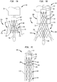
Figures 3 and4 illustrate a collapsible multi-layer stent orframe 100, which is part of a collapsible prosthetic heart valve. As discussed in detail below, the collapsible prosthetic heart valve also includes avalve assembly 200 supported by thestent 100, as seen inFigure 5 . Thestent 100 may be wholly or partly made of any biocompatible material suitable for allowing the stent to expand and collapse. Suitable biocompatible materials include, but are not limited to, metals or metal alloys, such as nitinol, synthetic polymers, or biopolymers capable of functioning as a stent. - The
stent 100 includes at least anaortic section 106 at one end, anannulus section 108 in the middle, and afoldable section 110 at the other end. Each of theaortic section 106,annulus section 108, andfoldable section 110 includes a plurality of cells. More particularly,aortic section 106 includes a plurality ofcells 101;annulus section 108 includes a plurality ofcells 102; andfoldable section 110 includes a plurality ofcells 103. Thestent 100 may be cut in one piece from a tube, such as by laser cutting. Alternatively, thestent 100 may be formed of several discrete pieces connected together. For example, theaortic section 106 andannulus section 108 may be formed together in one piece, whilefoldable section 110 may be formed as a separate piece and subsequently connected to theannulus section 108. In such embodiment,foldable section 110 may be attached to theannulus section 108 by sutures, wires, welding or any other suitable attachment method or means. The point of attachment of thefoldable section 110 to theannulus section 108 may be located at thefirst end 130 of the annulus section or at thesecond end 132 of the annulus section. Alternatively, thefoldable section 110 may be attached to theannulus section 108 by a sliding connection coupled to both thefirst end 130 and thesecond end 132 of the annulus section. - The
cells 101 ofaortic section 106 may be arranged in one or more annular rows extending around the circumference of the aortic section. Whenstent 100 is in the expanded condition, thecells 101 ofaortic section 106 may have substantially a diamond shape. As seen inFigure 3 , whenstent 100 is in the expanded condition, theaortic section 106 may have a circumference or diameter which increases in size from the end of the aortic section connected to theannulus section 108 to the free end of the aortic section. Theaortic section 106 may include retainingmembers 129, such as eyelets, at itsfree end 131. The retainingmembers 129 are intended to engage in corresponding recesses in the delivery device to holdstent 100 in a fixed and controllable position during delivery and placement of the stent in a patient. - In the expanded condition of
stent 100, theannulus section 108 may have a substantially uniform circumference or diameter along its length fromfirst end 130 tosecond end 132. Each of thecells 102 of theannulus section 108 may be formed by fourstruts 104 which together define substantially diamond shaped cells whenstent 100 is in the expanded condition. Thestruts 104 of eachcell 102 are connected to one another in end to end fashion, with the connections each occurring at a cell corner. Eachcell 102 has fourcell corners Corners cell 102 are substantially aligned in the circumferential direction of thestent 100, whilecorners - The angle α formed between
adjacent struts 104 atcorners cell 102 may be substantially identical throughout the entirety of theannulus section 108. The angle α may be equal to or greater than about 90°. Preferably, angle α may be about 110°. The angle α at the longitudinal ends of thecells 102 affects the elongation of theannulus section 108 when subjected to compressive forces by a delivery system. The elongation of the annulus section is directly proportional to the angle α at thecell corners annulus section 108 when the stent is compressed.Annulus section 108 preferably will exhibit a percent elongation from the expanded condition to the compressed condition of between about 30% and about 50%, with an elongation of about 50% being preferred. - The
foldable section 110 is connected at itsfirst end 134 to theannulus section 108 and may also includeenlarged eyelets 128 at itsfree end 136. Theeyelets 128 may be used for suturing the commissures of the prosthetic valve assembly to thestent 100, thereby attaching the prosthetic valve assembly to the stent. In addition, theeyelets 128 may be used for suturing thefoldable section 110 to thefirst end 130 of theannulus section 108 when the foldable section is in the folded condition to prevent excessive flexing of the foldable section. Excessive flexing of thefoldable section 110 should be avoided as it could cause fatigue fractures. - As noted previously, the
foldable section 110 includes a plurality ofcells 103, which may be arranged in one or more annular rows extending around the circumference of thefoldable section 110. Eachcell 103 of thefoldable section 110 may be formed by fourstruts 105, which together define a substantially diamond shape whenstent 100 is in the expanded condition. Thestruts 105 of eachcell 103 are connected to one another in end to end fashion, with each connection occurring at a cell corner. Eachcell 103 has fourcell corners Corners corners cell 103 are substantially aligned in the axial direction of the stent. - The angle β formed between
adjacent struts 105 atcorners cell 103 is preferably smaller than angle α, and may be acute. The angle β may range from about 50° to about 70°, and preferably is about 60°. The angle β at the longitudinal ends of thecells 103 affects the elongation of thefoldable section 110 when subjected to compressive forces by a delivery system. The elongation of thefoldable section 110 is directly proportional to the angle β at thecell corners foldable section 110 when it is compressed. - As a result of its larger cell angles α, the
annulus section 108 has a higher percent elongation than thefoldable section 110. For instance, theannulus section 108 may have a percent elongation ranging from about 30% to about 50%, whilefoldable section 110 may have a percent elongation ranging from about 7% to about 10%. An elongation of about 10% for thefoldable section 110 is highly preferred. - The
valve assembly 200 should not be attached to a section of thestent 100 having a high elongation since the large stent distortion during compression may cause the valve assembly to tear or become detached from the stent. Rather, thevalve assembly 200 should be attached to a section of the stent having a lower elongation during compression to prevent the valve assembly from being damaged. Accordingly, thevalve assembly 200 preferably is attached to thefoldable section 110 which exhibits a significantly lower elongation during its compression thanannulus section 108. - The
foldable section 110 may be inverted or folded under theannulus section 108 before use, as seen inFigure 4 . To this end,foldable section 110 includes a plurality ofbendable struts 138 at itsfirst end 134. The bendable struts 138 couplefoldable section 110 toannulus section 108 and allow the foldable section to be inverted under the annulus section. - As seen in
Figures 5 ,6a, 6b and 6c , avalve assembly 200 may be attached to the interior offoldable section 110 ofstent 100. Thevalve assembly 200 includes a plurality ofleaflets 202, which collectively function as a one-way valve, and which may be wholly or partly formed of tissue or any suitable polymer. Suitable valve assemblies are described inU.S Patent No. 8,092,523 andU.S. Patent Application Publication No. 2008/0147179, filed December 19, 2007 . Thevalve assembly 200 may also include acuff 204 disposed in an interior and/or exterior portion offoldable section 110 adjacent theleaflets 202. Thecuff 204 may be foldable along withfoldable section 110, as seen inFigure 6a . At least a portion of thecuff 204 may be attached tobendable struts 138, to theannulus section 108 ofstent 100, and/or to the interior and/or exterior (in the unfolded condition) of thefoldable section 110. -
Figure 5 shows thevalve assembly 200 attached to the interior of thefoldable section 110 ofstent 100 in the unfolded condition. Thevalve assembly 200 is attached to thefoldable section 110 ofstent 100 so that, when the foldable section is inverted underannulus section 108, as illustrated inFigure 6a , theleaflets 202 of the valve assembly permit blood to flow from the annulus section to theaortic section 106 of the stent, while preventing blood from flowing from the aortic section to the annulus section. Rather than being attached to the interior offoldable section 110 of thestent 100, thevalve assembly 200 may be attached to the interior of theannulus section 108 of the stent. For reasons discussed above regarding potential damage to thevalve assembly 200 on compression of the stent, however, attachment toannulus section 108 is less preferred. - During operation, the collapsible prosthetic heart valve, including
stent 100 andvalve assembly 200, may be implanted in a native valve annulus of a patient with thefoldable section 110 in the folded condition, as shown inFigures 6a, 6b, and 6c . Thefoldable section 110 ofstent 100 may be inverted to its folded condition during assembly or during deployment. Whenfoldable section 110 is in the folded condition, it is at least partially positioned within theannulus section 108 of thestent 100. At this point, thevalve assembly 200 is attached to thefoldable section 110, which has a low elongation during compression ofstent 100. Due to the low elongation offoldable section 110, thevalve assembly 200 is less likely to be damaged during initial compression ofstent 100 or during a resheathing procedure, should that become necessary. On the other hand, theannulus section 108 has a larger elongation during compression ofstent 100, but requires small forces to be radially compressed, thereby facilitating resheathing. The size of angles α formed betweenadjacent struts 104 at thecorners cell 102 allows the force applied in the axial direction tostent 100 as a delivery sheath is slid thereover to be more effectively translated to radial compression. The size of cell corner angles α in theannulus section 108 also allows the same force to be achieved with thinner struts because the force components are directed more along the length of the strut. As a consequence, the entire collapsible prosthetic heart valve can be pulled safely into the delivery sheath via theannulus section 108 ofstent 100. -
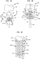
Figures 7a, 7b, and 7c illustrate another example, not according to the present invention, of acollapsible heart valve 299 and a method of implanting the same near a native valve annulus. This collapsibleprosthetic heart valve 299 includes a stent orframe 300 and avalve assembly 400. Thestent 300 is made entirely or partly of a suitable shape memory material having an unstressed state and a deformed state. Suitable shape memory materials include biocompatible shape memory metals or alloys, such as nitinol, and biocompatible shape memory polymers. - The
stent 300 has an expanded and unfolded condition, as seen inFigure 7b , an expanded and folded condition, such as seen inFigure 7a , and a collapsed and unfolded condition, as seen inFigure 7c . Thestent 300 includes anannulus section 308, aclamping section 309, and a foldable orinvertible section 310. Each of theannulus section 308, clampingsection 309, and foldable orinvertible section 310 includes a plurality ofcells 306 extending around its periphery. Sinceheart valve 299 captures at least a portion of the native valve leaflets between the clampingsection 309 and thefoldable section 310 on deployment, as will be described further below, thereby holding the heart valve in place in the native valve annulus,stent 300 need not be formed with an aortic section. - The
annulus section 308 of thestent 300 is located at one end of the stent and may have a substantially cylindrical shape when the stent is in the expanded condition, as seen inFigure 7b . One ormore retaining members 312, such as eyelets, may be provided at the free end of theannulus section 308 for connecting thestent 300 to adelivery system 500 during delivery and placement of the stent in a patient. Thefoldable section 310 of thestent 300 may be connected to theannulus section 308 and may have a substantially frusto-conical shape when the stent is in the expanded condition, as seen inFigure 7b . When thestent 300 is in the collapsed condition, on the other hand, thefoldable section 310 may have a substantially cylindrical shape, as seen inFigure 7c . Thefoldable section 310 includes a firstbendable portion 314 near its connection toannulus section 308. Thefoldable section 310 may be inverted at the firstbendable portion 314 and folded over at least a portion of theannulus section 308. - The
clamping section 309 of thestent 300 may be connected to thefoldable section 310 at the other end ofstent 300 and may also have a substantially frusto-conical shape when the stent is in an expanded condition, as seen inFigure 7b , and a substantially cylindrical shape when the stent is in the collapsed condition, as seen inFigure 7c . A secondbendable portion 316 near the connection offoldable section 310 to clampingsection 309 enables the clamping section to be inverted and folded in the opposite direction back over the foldable section, as seen inFigure 7a . - A
valve assembly 400 may be attached to the inner surface of theannulus section 308 and may include acuff 404 and a plurality ofleaflets 402 attached to the cuff and/or tostent 300. Theleaflets 402 collectively function as a one-way valve. Thevalve assembly 400 may be entirely or partly made of tissue or any suitable polymer. - The
prosthetic heart valve 299 depicted inFigures 7a-7c may be implanted in a native valve annulus of a patient using any suitable delivery system, such asdelivery system 500.Delivery system 500 includes asupport shaft 506 around which the collapsed valve may be mounted, and adistal sheath 504 slidable relative to the support shaft to selectively cover and uncover the valve. A retainingelement 502 mounted on thesupport shaft 506 may include recesses to securely receive the retainingmembers 312 of thestent 300. - The
delivery system 500 may be used to implant the collapsibleprosthetic heart valve 299 transfemorally or transapically. Other delivery methods are also envisioned, including the use of a trans-subclavian approach. Before inserting theprosthetic heart valve 299 into the patient, the heart valve should be mounted around thesupport shaft 506 of thedelivery system 500 in the collapsed and unfolded condition, as seen inFigure 7c , with retainingmembers 312 positioned in the recesses of the retainingelement 502. Subsequently, thedistal sheath 504 should be slid over the valve to hold it in the collapsed condition for delivery. Thedelivery system 500 may then be inserted into the patient until thedistal sheath 504 reaches the desired site (e.g., the native valve annulus). Once at the desired site, the user may slide thedistal sheath 504 relative to thesupport shaft 506 to uncover a portion of thestent 300, as seen inFigure 7b , to initiate deployment ofheart valve 299. If theheart valve 299 is being deployed in the correct position, the user may expose theentire stent 300 to complete the deployment process. Otherwise, the user may slide thedistal sheath 504 in the opposite direction to again cover thestent 300 and reposition thedelivery system 500 to the correct position. - When the
heart valve 299 has been completely deployed, thestent 300 automatically converts from the unfolded shape (i.e., stressed state), as seen inFigure 7b , to the folded shape (i.e., unstressed state), as seen inFigure 7a . During this conversion, the firstbendable portion 314 of thefoldable section 310 bends to invert the foldable section over at least a portion ofannulus section 308. The secondbendable portion 316 of thefoldable section 310 also bends, but in the opposite direction, to fold theclamping section 309 back over at least a portion of thefoldable section 310. Thus, in the folded condition ofstent 300, theclamping section 309 is positioned radially outward of thefoldable section 310 and thevalve assembly 400. As theclamping section 309 folds back over thefoldables section 310, it captures at least a portion of the native leaflets L and sandwiches them between the clamping section and thefoldable section 310, as seen inFigure 7a . This clamping of the foldedstent 300 to the native valve leaflets L acts to secureheart valve 299 in the native valve annulus. - When the
stent 300 is in the expanded and folded condition as seen inFigure 7a , at least a portion of thecuff 404 of thevalve assembly 400 may extend beyond the firstbendable portion 314 and may contact the native leaflets L to help prevent regurgitation of blood between the native leaflets and the outer portion of the valve assembly. That is, the contact between thecuff 404 and the native leaflets helps to prevent paravalvular leaks. - While the foregoing describes the deployment of
prosthetic heart valve 299 in the native annulus of a patient to replace the patient's native valve, in certain circumstances, prosthetic heart valve 299 (as well as the other prosthetic heart valves described herein) may be deployed within a previously implanted prosthetic heart valve that is no longer performing optimally. In that situation, theprosthetic heart valve 299 may be deployed in the manner described above. However, rather than having a portion of native valve leaflets L captured as clampingsection 309 folds back over at least a portion offoldable section 310, the clamping section may capture the prosthetic leaflets or stent frame of the previously implanted prosthetic heart valve in order to hold the newly inserted heart valve in its implanted position. -
Figures 8a-8c show another collapsibleprosthetic heart valve 599 not according to an embodiment of the present invention. This heart valve includes an expandable/collapsible stent orframe 600 made partly or entirely of a shape memory material. Thestent 600 includes anannulus section 608 and afoldable section 610 and, as withheart valve 299 described above, may eliminate an aortic section. Each of theannulus section 608 and thefoldable section 610 includes a plurality of cells extending around its periphery, enablingstent 600 to move between an expanded condition and a collapsed condition. When thestent 600 is in the collapsed condition, theannulus section 608 and thefoldable section 610 may each have a substantially cylindrical shape, as shown inFigure 8c . - The
foldable section 610 has afirst region 612adjacent annulus section 608 and asecond region 614 spaced from the annulus section, with the two regions being divided by afolding line 616. As a result, thefoldable section 610 can bend along thefolding line 616 between an unstressed folded condition, as seen inFigure 8a , and a deformed condition, as seen inFigure 8c , in which thefoldable section 610 is unfolded. In the deformed condition, in which thefoldable section 610 is stressed,stent 600 has a substantially cylindrical configuration, with thefirst region 612 of the foldable section positioned between thesecond region 614 thereof and theannulus section 608. In the unstressed folded condition, thefirst region 612 of thefoldable section 610 may be inverted and folded over at least a portion of theannulus section 608 of thestent 600, and thesecond region 614 of the foldable section may be inverted and folded in the opposite direction back over at least a portion of thefirst region 612. Thesecond region 614 offoldable section 610 may include one ormore retaining members 620, such as eyelets, for facilitating a secure attachment betweenstent 600 and adelivery system 800. - A
valve assembly 700 may be attached to the inner surface of theannulus section 608 and may include acuff 704 and a plurality ofleaflets 702 attached to the cuff and/or tostent 600. Theleaflets 702 collectively function as a one-way valve. Thevalve assembly 700 may be entirely or partially made of a suitable polymer or tissue. - The prosthetic heart valve depicted in
Figures 8a-8c may be implanted in a native valve annulus of a patient using a transfemoral approach, a transapical approach, a trans-subclavian approach, and by other known methods using any suitable delivery system, including thedelivery system 800. Thedelivery system 800 includes asupport shaft 804 around which the collapsed valve may be mounted, and adistal sheath 802 slidable relative to the support shaft to selectively cover and uncover the valve. A retainingelement 806 mounted on thesupport shaft 804 includes recesses adapted to receive the retainingmembers 620 of thestent 600 for attaching the stent to thedelivery system 800. - Before inserting the
prosthetic heart valve 599 depicted inFigures 8a-8c into the patient, the heart valve should be mounted around thesupport shaft 804 of thedelivery system 800 in the collapsed and unfolded condition, as shown inFigure 8c , with the retainingmembers 620 positioned in the recesses of the retainingelement 806. Thedistal sheath 802 should then be slid over the valve to hold the valve in the collapsed condition for delivery. Thedelivery system 800 may then be inserted into the patient until thedistal sheath 802 reaches the desired site (e.g., the native valve annulus). During insertion, thedistal sheath 802 maintains thestent 600 in the deformed (i.e., unfolded) state, as seen inFigure 8c . Thedistal sheath 802 may then be slid relative to thesupport shaft 804 to uncover at least a portion of thestent 600 for deployment ofheart valve 599. The user may then determine if theheart valve 599 is being deployed at the correct position. If a correction is necessary, the user may slide thedistal sheath 802 in the opposite direction to again cover thestent 600, and may reposition thedelivery system 800 at the proper location. Once thedelivery system 800 is at the correct location, the user may again slide thedistal sheath 802 to uncover thestent 600 and deploy the heart valve. Upon complete deployment ofheart valve 599, thestent 600 automatically converts from its deformed condition (i.e., stressed state), as shown inFigure 8c , to its folded condition (i.e., unstressed state), as shown inFigure 8a . During this conversion, thefirst region 612 of thefoldable section 610 inverts and folds over at least a portion of theannulus section 608. This action causes thefirst region 612 to deflect toward the native leaflets L and to urge the leaflets toward theannulus section 608 of the stent, sandwiching them between the first region and the annulus section, as seen inFigure 8a . Thesecond region 614 of thestent 600 also inverts and folds in the opposite direction back over at least a portion of thefirst region 612. The clamping of the native leaflets L between theannulus section 608 and thefirst region 612 acts to secureheart valve 599 in the native valve annulus. - Although the invention herein has been described with reference to particular embodiments, it is to be understood that these embodiments are merely illustrative of the principles and applications of the present invention. It is therefore to be understood that numerous modifications may be made to the illustrative embodiments and that other arrangements may be devised without departing from the scope of the present invention as defined by the appended claims. For example, any of the prosthetic heart valves described herein may be used to replace the mitral valve, tricuspid valve, aortic valve or pulmonic valve. In addition, the prosthetic heart valves described herein may be implanted within a previously implanted prosthetic valve.
- The prosthetic heart valves of the present invention are useful for replacing native heart valves that no longer function properly.
Claims (10)
- A collapsible prosthetic heart valve, comprising:a stent (100) including a foldable section (110), an annulus section (108), and an aortic section (106) arranged in series, the stent having a collapsed condition and an expanded condition and being movable between an unfolded condition in which the foldable section is spaced from the annulus section in a longitudinal direction, and a folded condition in which the foldable section is at least partially positioned within the annulus section; anda valve assembly (200) attached to the foldable section of the stent,the annulus section lengthening in the longitudinal direction by a first elongation percentage upon movement from the expanded condition to the collapsed condition, and the foldable section lengthening in the longitudinal direction by a second elongation percentage upon movement from the expanded condition to the collapsed condition, the first elongation percentage being greater than the second elongation percentage.
- The collapsible prosthetic heart valve according to claim 1, wherein the annulus section includes a plurality of cells (102), each cell having a substantially diamond shape with four corners (112, 114, 116, 118) when the stent is in the expanded condition.
- The collapsible prosthetic heart valve according to claim 2, wherein each cell in the annulus section includes two corners (114, 118) substantially aligned with one another in the longitudinal direction, the aligned corners each defining an obtuse angle (α).
- The collapsible prosthetic heart valve according to claim 1, wherein the foldable section includes a plurality of cells (103), each cell having a substantially diamond shape with four corners (120, 122, 124, 126) when the stent is in the expanded condition.
- The collapsible prosthetic heart valve according to claim 4, wherein each cell in the foldable section includes two corners (122, 126) substantially aligned with one another in the longitudinal direction, the aligned corners each defining an acute angle (β).
- The collapsible prosthetic heart valve according to claim 1, wherein the foldable section, the annulus section and the aortic section are formed integrally with one another.
- The collapsible prosthetic heart valve according to claim 1, wherein the foldable section is formed separately from the annulus section and connected to the annulus section.
- The collapsible prosthetic heart valve according to claim 1, wherein the valve assembly includes a cuff (204) and a plurality of leaflets (202).
- The collapsible prosthetic heart valve according to claim 8, wherein at least a portion of the cuff is attached inside the annulus section.
- The collapsible prosthetic heart valve according to claim 1, wherein the annulus section includes a plurality of cells (102) and the foldable section includes a plurality of cells (103), each cell having a substantially diamond shape with four corners (112, 114, 116, 118; 120, 122, 124, 126) when the stent is in the expanded condition, each cell in the annulus section including two corners (114, 118) substantially aligned with one another in the longitudinal direction, each cell in the foldable section including two corners (122, 126) substantially aligned with one another in the longitudinal direction, each of the aligned corners in the annulus section defining a larger angle (α) than each of the aligned corners in the foldable section.
Applications Claiming Priority (2)
| Application Number | Priority Date | Filing Date | Title |
|---|---|---|---|
| US201161497291P | 2011-06-15 | 2011-06-15 | |
| PCT/US2012/042059 WO2012173995A2 (en) | 2011-06-15 | 2012-06-12 | Multi-layer stent |
Publications (2)
| Publication Number | Publication Date |
|---|---|
| EP2720641A2 EP2720641A2 (en) | 2014-04-23 |
| EP2720641B1 true EP2720641B1 (en) | 2019-02-20 |
Family
ID=46457011
Family Applications (1)
| Application Number | Title | Priority Date | Filing Date |
|---|---|---|---|
| EP12731792.3A Active EP2720641B1 (en) | 2011-06-15 | 2012-06-12 | Prosthetic heart valve with multi-layer stent |
Country Status (3)
| Country | Link |
|---|---|
| US (3) | US9532887B2 (en) |
| EP (1) | EP2720641B1 (en) |
| WO (1) | WO2012173995A2 (en) |
Cited By (13)
| Publication number | Priority date | Publication date | Assignee | Title |
|---|---|---|---|---|
| US10856984B2 (en) | 2017-08-25 | 2020-12-08 | Neovasc Tiara Inc. | Sequentially deployed transcatheter mitral valve prosthesis |
| US10940001B2 (en) | 2012-05-30 | 2021-03-09 | Neovasc Tiara Inc. | Methods and apparatus for loading a prosthesis onto a delivery system |
| US11311376B2 (en) | 2019-06-20 | 2022-04-26 | Neovase Tiara Inc. | Low profile prosthetic mitral valve |
| US11357622B2 (en) | 2016-01-29 | 2022-06-14 | Neovase Tiara Inc. | Prosthetic valve for avoiding obstruction of outflow |
| US11389291B2 (en) | 2013-04-04 | 2022-07-19 | Neovase Tiara Inc. | Methods and apparatus for delivering a prosthetic valve to a beating heart |
| US11413139B2 (en) | 2011-11-23 | 2022-08-16 | Neovasc Tiara Inc. | Sequentially deployed transcatheter mitral valve prosthesis |
| US11419720B2 (en) | 2010-05-05 | 2022-08-23 | Neovasc Tiara Inc. | Transcatheter mitral valve prosthesis |
| US11464631B2 (en) | 2016-11-21 | 2022-10-11 | Neovasc Tiara Inc. | Methods and systems for rapid retraction of a transcatheter heart valve delivery system |
| US11491006B2 (en) | 2019-04-10 | 2022-11-08 | Neovasc Tiara Inc. | Prosthetic valve with natural blood flow |
| US11497602B2 (en) | 2012-02-14 | 2022-11-15 | Neovasc Tiara Inc. | Methods and apparatus for engaging a valve prosthesis with tissue |
| US11602429B2 (en) | 2019-04-01 | 2023-03-14 | Neovasc Tiara Inc. | Controllably deployable prosthetic valve |
| US11779742B2 (en) | 2019-05-20 | 2023-10-10 | Neovasc Tiara Inc. | Introducer with hemostasis mechanism |
| US11998447B2 (en) | 2019-03-08 | 2024-06-04 | Neovasc Tiara Inc. | Retrievable prosthesis delivery system |
Families Citing this family (30)
| Publication number | Priority date | Publication date | Assignee | Title |
|---|---|---|---|---|
| US9155619B2 (en) | 2011-02-25 | 2015-10-13 | Edwards Lifesciences Corporation | Prosthetic heart valve delivery apparatus |
| EP4049625A1 (en) | 2011-12-09 | 2022-08-31 | Edwards Lifesciences Corporation | Prosthetic heart valve having improved commissure supports |
| US9066801B2 (en) | 2013-01-08 | 2015-06-30 | Medtronic, Inc. | Valve prosthesis and method for delivery |
| US9439763B2 (en) * | 2013-02-04 | 2016-09-13 | Edwards Lifesciences Corporation | Prosthetic valve for replacing mitral valve |
| US9744032B2 (en) | 2013-03-11 | 2017-08-29 | Cook Medical Technologies Llc | Endoluminal prosthesis comprising a valve and an axially extendable segment |
| CN109199639B (en) * | 2013-03-15 | 2021-07-16 | 托尔福公司 | Prosthetic heart valve devices, prosthetic mitral valves, and associated systems and methods |
| EP3231394A1 (en) | 2013-03-15 | 2017-10-18 | Hlt, Inc. | Low-profile prosthetic valve structure |
| US10953141B2 (en) | 2013-05-23 | 2021-03-23 | S.T.S. Medical Ltd. | Shape change structure |
| CN103431926B (en) * | 2013-09-04 | 2015-09-30 | 杭州启明医疗器械有限公司 | For intervention apparatus conveying sheath core and there is the induction system of this sheath core |
| WO2015120122A2 (en) * | 2014-02-05 | 2015-08-13 | Robert Vidlund | Apparatus and methods for transfemoral delivery of prosthetic mitral valve |
| EP3160388B1 (en) | 2014-06-26 | 2021-08-11 | Boston Scientific Scimed Inc. | Medical devices to prevent bile reflux after bariatric procedures |
| WO2016084087A2 (en) | 2014-11-26 | 2016-06-02 | S.T.S. Medical Ltd. | Shape change structure for treatment of nasal conditions including sinusitis |
| AU2016205371B2 (en) * | 2015-01-07 | 2019-10-10 | Tendyne Holdings, Inc. | Prosthetic mitral valves and apparatus and methods for delivery of same |
| ES2877699T3 (en) | 2015-02-05 | 2021-11-17 | Tendyne Holdings Inc | Prosthetic Heart Valve with Ligation and Expandable Epicardial Pad |
| JP6755888B2 (en) * | 2015-05-14 | 2020-09-16 | エドワーズ ライフサイエンシーズ コーポレイションEdwards Lifesciences Corporation | Heart valve sealing device and its delivery device |
| EP3307207A1 (en) | 2015-06-12 | 2018-04-18 | St. Jude Medical, Cardiology Division, Inc. | Heart valve repair and replacement |
| US10357363B2 (en) * | 2016-06-09 | 2019-07-23 | Medtronic Vascular, Inc. | Transcatheter valve delivery system with crimped prosthetic heart valve |
| CN109640887B (en) * | 2016-06-30 | 2021-03-16 | 坦迪尼控股股份有限公司 | Prosthetic heart valve and apparatus and method for delivering same |
| CN110167491A (en) | 2016-11-09 | 2019-08-23 | 波士顿科学国际有限公司 | Bracket with displacement capacity |
| US10653523B2 (en) | 2017-01-19 | 2020-05-19 | 4C Medical Technologies, Inc. | Systems, methods and devices for delivery systems, methods and devices for implanting prosthetic heart valves |
| US10561495B2 (en) | 2017-01-24 | 2020-02-18 | 4C Medical Technologies, Inc. | Systems, methods and devices for two-step delivery and implantation of prosthetic heart valve |
| US12029647B2 (en) | 2017-03-07 | 2024-07-09 | 4C Medical Technologies, Inc. | Systems, methods and devices for prosthetic heart valve with single valve leaflet |
| US12036113B2 (en) * | 2017-06-14 | 2024-07-16 | 4C Medical Technologies, Inc. | Delivery of heart chamber prosthetic valve implant |
| AU2019269740B2 (en) * | 2018-05-18 | 2023-11-23 | Anteris Technologies Corporation | Inverted heart valve for transcatheter valve replacement |
| US11857441B2 (en) | 2018-09-04 | 2024-01-02 | 4C Medical Technologies, Inc. | Stent loading device |
| US11786355B2 (en) | 2020-01-30 | 2023-10-17 | Boston Scientific Scimed, Inc. | Radial adjusting self-expanding stent with anti-migration features |
| US11931253B2 (en) | 2020-01-31 | 2024-03-19 | 4C Medical Technologies, Inc. | Prosthetic heart valve delivery system: ball-slide attachment |
| US12053375B2 (en) | 2020-03-05 | 2024-08-06 | 4C Medical Technologies, Inc. | Prosthetic mitral valve with improved atrial and/or annular apposition and paravalvular leakage mitigation |
| US11992403B2 (en) | 2020-03-06 | 2024-05-28 | 4C Medical Technologies, Inc. | Devices, systems and methods for improving recapture of prosthetic heart valve device with stent frame having valve support with inwardly stent cells |
| EP4199860A1 (en) | 2020-08-19 | 2023-06-28 | Tendyne Holdings, Inc. | Fully-transseptal apical pad with pulley for tensioning |
Family Cites Families (22)
| Publication number | Priority date | Publication date | Assignee | Title |
|---|---|---|---|---|
| WO2003092554A1 (en) * | 2002-05-03 | 2003-11-13 | The General Hospital Corporation | Involuted endovascular valve and method of construction |
| US7261732B2 (en) * | 2003-12-22 | 2007-08-28 | Henri Justino | Stent mounted valve |
| US7381219B2 (en) | 2003-12-23 | 2008-06-03 | Sadra Medical, Inc. | Low profile heart valve and delivery system |
| US8828078B2 (en) | 2003-12-23 | 2014-09-09 | Sadra Medical, Inc. | Methods and apparatus for endovascular heart valve replacement comprising tissue grasping elements |
| EP3292838A1 (en) * | 2005-05-24 | 2018-03-14 | Edwards Lifesciences Corporation | Rapid deployment prosthetic heart valve |
| CN101991478B (en) * | 2005-05-27 | 2013-04-24 | 心叶科技公司 | Stentless support structure |
| US20080275540A1 (en) * | 2005-11-09 | 2008-11-06 | Ning Wen | Artificial Heart Valve Stent and Weaving Method Thereof |
| WO2008079272A2 (en) | 2006-12-19 | 2008-07-03 | St. Jude Medical, Inc. | Prosthetic heart valve including stent structure and tissue leaflets, and related methods |
| US8236045B2 (en) * | 2006-12-22 | 2012-08-07 | Edwards Lifesciences Corporation | Implantable prosthetic valve assembly and method of making the same |
| WO2008091515A2 (en) | 2007-01-19 | 2008-07-31 | Medtronic, Inc. | Stented heart valve devices and methods for atrioventricular valve replacement |
| WO2008097589A1 (en) | 2007-02-05 | 2008-08-14 | Boston Scientific Limited | Percutaneous valve, system, and method |
| US8092523B2 (en) | 2007-03-12 | 2012-01-10 | St. Jude Medical, Inc. | Prosthetic heart valves with flexible leaflets |
| EP2025306B1 (en) * | 2007-04-23 | 2020-01-01 | Saint Joseph Research Institute | Methods of making a replacement heart valve |
| WO2008150529A1 (en) * | 2007-06-04 | 2008-12-11 | St. Jude Medical, Inc. | Prosthetic heart valves |
| US8728154B2 (en) * | 2007-08-24 | 2014-05-20 | St. Jude Medical, Inc. | Prosthetic aortic heart valves |
| US8163004B2 (en) * | 2008-02-18 | 2012-04-24 | Aga Medical Corporation | Stent graft for reinforcement of vascular abnormalities and associated method |
| US9232992B2 (en) * | 2008-07-24 | 2016-01-12 | Aga Medical Corporation | Multi-layered medical device for treating a target site and associated method |
| BRPI1008902A2 (en) * | 2009-02-27 | 2016-03-15 | St Jude Medical | prosthetic heart valve. |
| US8449599B2 (en) * | 2009-12-04 | 2013-05-28 | Edwards Lifesciences Corporation | Prosthetic valve for replacing mitral valve |
| US8795354B2 (en) | 2010-03-05 | 2014-08-05 | Edwards Lifesciences Corporation | Low-profile heart valve and delivery system |
| US10016271B2 (en) * | 2011-10-19 | 2018-07-10 | Twelve, Inc. | Prosthetic heart valve devices, prosthetic mitral valves and associated systems and methods |
| CN104540473B (en) | 2012-02-01 | 2017-06-23 | Hlt 公司 | Turnover tissue valve prosthesis and method |
-
2012
- 2012-06-12 EP EP12731792.3A patent/EP2720641B1/en active Active
- 2012-06-12 US US14/124,092 patent/US9532887B2/en active Active
- 2012-06-12 WO PCT/US2012/042059 patent/WO2012173995A2/en active Application Filing
-
2016
- 2016-11-30 US US15/365,040 patent/US20170079787A1/en not_active Abandoned
-
2019
- 2019-04-16 US US16/385,481 patent/US11426274B2/en active Active
Non-Patent Citations (1)
| Title |
|---|
| None * |
Cited By (19)
| Publication number | Priority date | Publication date | Assignee | Title |
|---|---|---|---|---|
| US11419720B2 (en) | 2010-05-05 | 2022-08-23 | Neovasc Tiara Inc. | Transcatheter mitral valve prosthesis |
| US11413139B2 (en) | 2011-11-23 | 2022-08-16 | Neovasc Tiara Inc. | Sequentially deployed transcatheter mitral valve prosthesis |
| US12053369B2 (en) | 2011-11-23 | 2024-08-06 | Neovasc Tiara Inc. | Sequentially deployed transcatheter mitral valve prosthesis |
| US11497602B2 (en) | 2012-02-14 | 2022-11-15 | Neovasc Tiara Inc. | Methods and apparatus for engaging a valve prosthesis with tissue |
| US11617650B2 (en) | 2012-05-30 | 2023-04-04 | Neovasc Tiara Inc. | Methods and apparatus for loading a prosthesis onto a delivery system |
| US11389294B2 (en) | 2012-05-30 | 2022-07-19 | Neovasc Tiara Inc. | Methods and apparatus for loading a prosthesis onto a delivery system |
| US10940001B2 (en) | 2012-05-30 | 2021-03-09 | Neovasc Tiara Inc. | Methods and apparatus for loading a prosthesis onto a delivery system |
| US11389291B2 (en) | 2013-04-04 | 2022-07-19 | Neovase Tiara Inc. | Methods and apparatus for delivering a prosthetic valve to a beating heart |
| US11357622B2 (en) | 2016-01-29 | 2022-06-14 | Neovase Tiara Inc. | Prosthetic valve for avoiding obstruction of outflow |
| US11464631B2 (en) | 2016-11-21 | 2022-10-11 | Neovasc Tiara Inc. | Methods and systems for rapid retraction of a transcatheter heart valve delivery system |
| US11793640B2 (en) | 2017-08-25 | 2023-10-24 | Neovasc Tiara Inc. | Sequentially deployed transcatheter mitral valve prosthesis |
| US10856984B2 (en) | 2017-08-25 | 2020-12-08 | Neovasc Tiara Inc. | Sequentially deployed transcatheter mitral valve prosthesis |
| US11998447B2 (en) | 2019-03-08 | 2024-06-04 | Neovasc Tiara Inc. | Retrievable prosthesis delivery system |
| US11602429B2 (en) | 2019-04-01 | 2023-03-14 | Neovasc Tiara Inc. | Controllably deployable prosthetic valve |
| US12036117B2 (en) | 2019-04-10 | 2024-07-16 | Neovasc Tiara Inc. | Prosthetic valve with natural blood flow |
| US11491006B2 (en) | 2019-04-10 | 2022-11-08 | Neovasc Tiara Inc. | Prosthetic valve with natural blood flow |
| US11779742B2 (en) | 2019-05-20 | 2023-10-10 | Neovasc Tiara Inc. | Introducer with hemostasis mechanism |
| US11311376B2 (en) | 2019-06-20 | 2022-04-26 | Neovase Tiara Inc. | Low profile prosthetic mitral valve |
| US11931254B2 (en) | 2019-06-20 | 2024-03-19 | Neovasc Tiara Inc. | Low profile prosthetic mitral valve |
Also Published As
| Publication number | Publication date |
|---|---|
| US9532887B2 (en) | 2017-01-03 |
| US20170079787A1 (en) | 2017-03-23 |
| US20190240009A1 (en) | 2019-08-08 |
| US20140243965A1 (en) | 2014-08-28 |
| EP2720641A2 (en) | 2014-04-23 |
| US11426274B2 (en) | 2022-08-30 |
| WO2012173995A2 (en) | 2012-12-20 |
| WO2012173995A3 (en) | 2013-09-19 |
Similar Documents
| Publication | Publication Date | Title |
|---|---|---|
| US11426274B2 (en) | Multi-layer stent | |
| US11020222B2 (en) | Perivalvular sealing for transcatheter heart valve | |
| US8414645B2 (en) | Transcatheter valve delivery systems and methods |
Legal Events
| Date | Code | Title | Description |
|---|---|---|---|
| PUAI | Public reference made under article 153(3) epc to a published international application that has entered the european phase |
Free format text: ORIGINAL CODE: 0009012 |
|
| 17P | Request for examination filed |
Effective date: 20131022 |
|
| AK | Designated contracting states |
Kind code of ref document: A2 Designated state(s): AL AT BE BG CH CY CZ DE DK EE ES FI FR GB GR HR HU IE IS IT LI LT LU LV MC MK MT NL NO PL PT RO RS SE SI SK SM TR |
|
| DAX | Request for extension of the european patent (deleted) | ||
| RAP1 | Party data changed (applicant data changed or rights of an application transferred) |
Owner name: ST. JUDE MEDICAL, LLC |
|
| GRAP | Despatch of communication of intention to grant a patent |
Free format text: ORIGINAL CODE: EPIDOSNIGR1 |
|
| STAA | Information on the status of an ep patent application or granted ep patent |
Free format text: STATUS: GRANT OF PATENT IS INTENDED |
|
| RIC1 | Information provided on ipc code assigned before grant |
Ipc: A61F 2/90 20130101ALN20180928BHEP Ipc: A61F 2/82 20130101ALN20180928BHEP Ipc: A61F 2/24 20060101AFI20180928BHEP |
|
| INTG | Intention to grant announced |
Effective date: 20181106 |
|
| GRAS | Grant fee paid |
Free format text: ORIGINAL CODE: EPIDOSNIGR3 |
|
| GRAA | (expected) grant |
Free format text: ORIGINAL CODE: 0009210 |
|
| STAA | Information on the status of an ep patent application or granted ep patent |
Free format text: STATUS: THE PATENT HAS BEEN GRANTED |
|
| AK | Designated contracting states |
Kind code of ref document: B1 Designated state(s): AL AT BE BG CH CY CZ DE DK EE ES FI FR GB GR HR HU IE IS IT LI LT LU LV MC MK MT NL NO PL PT RO RS SE SI SK SM TR |
|
| REG | Reference to a national code |
Ref country code: GB Ref legal event code: FG4D |
|
| REG | Reference to a national code |
Ref country code: CH Ref legal event code: EP |
|
| REG | Reference to a national code |
Ref country code: DE Ref legal event code: R096 Ref document number: 602012056808 Country of ref document: DE |
|
| REG | Reference to a national code |
Ref country code: AT Ref legal event code: REF Ref document number: 1097191 Country of ref document: AT Kind code of ref document: T Effective date: 20190315 |
|
| REG | Reference to a national code |
Ref country code: IE Ref legal event code: FG4D |
|
| REG | Reference to a national code |
Ref country code: NL Ref legal event code: MP Effective date: 20190220 |
|
| REG | Reference to a national code |
Ref country code: LT Ref legal event code: MG4D |
|
| PG25 | Lapsed in a contracting state [announced via postgrant information from national office to epo] |
Ref country code: PT Free format text: LAPSE BECAUSE OF FAILURE TO SUBMIT A TRANSLATION OF THE DESCRIPTION OR TO PAY THE FEE WITHIN THE PRESCRIBED TIME-LIMIT Effective date: 20190620 Ref country code: SE Free format text: LAPSE BECAUSE OF FAILURE TO SUBMIT A TRANSLATION OF THE DESCRIPTION OR TO PAY THE FEE WITHIN THE PRESCRIBED TIME-LIMIT Effective date: 20190220 Ref country code: NO Free format text: LAPSE BECAUSE OF FAILURE TO SUBMIT A TRANSLATION OF THE DESCRIPTION OR TO PAY THE FEE WITHIN THE PRESCRIBED TIME-LIMIT Effective date: 20190520 Ref country code: FI Free format text: LAPSE BECAUSE OF FAILURE TO SUBMIT A TRANSLATION OF THE DESCRIPTION OR TO PAY THE FEE WITHIN THE PRESCRIBED TIME-LIMIT Effective date: 20190220 Ref country code: NL Free format text: LAPSE BECAUSE OF FAILURE TO SUBMIT A TRANSLATION OF THE DESCRIPTION OR TO PAY THE FEE WITHIN THE PRESCRIBED TIME-LIMIT Effective date: 20190220 Ref country code: LT Free format text: LAPSE BECAUSE OF FAILURE TO SUBMIT A TRANSLATION OF THE DESCRIPTION OR TO PAY THE FEE WITHIN THE PRESCRIBED TIME-LIMIT Effective date: 20190220 |
|
| PG25 | Lapsed in a contracting state [announced via postgrant information from national office to epo] |
Ref country code: BG Free format text: LAPSE BECAUSE OF FAILURE TO SUBMIT A TRANSLATION OF THE DESCRIPTION OR TO PAY THE FEE WITHIN THE PRESCRIBED TIME-LIMIT Effective date: 20190520 Ref country code: GR Free format text: LAPSE BECAUSE OF FAILURE TO SUBMIT A TRANSLATION OF THE DESCRIPTION OR TO PAY THE FEE WITHIN THE PRESCRIBED TIME-LIMIT Effective date: 20190521 Ref country code: IS Free format text: LAPSE BECAUSE OF FAILURE TO SUBMIT A TRANSLATION OF THE DESCRIPTION OR TO PAY THE FEE WITHIN THE PRESCRIBED TIME-LIMIT Effective date: 20190620 Ref country code: HR Free format text: LAPSE BECAUSE OF FAILURE TO SUBMIT A TRANSLATION OF THE DESCRIPTION OR TO PAY THE FEE WITHIN THE PRESCRIBED TIME-LIMIT Effective date: 20190220 Ref country code: LV Free format text: LAPSE BECAUSE OF FAILURE TO SUBMIT A TRANSLATION OF THE DESCRIPTION OR TO PAY THE FEE WITHIN THE PRESCRIBED TIME-LIMIT Effective date: 20190220 Ref country code: RS Free format text: LAPSE BECAUSE OF FAILURE TO SUBMIT A TRANSLATION OF THE DESCRIPTION OR TO PAY THE FEE WITHIN THE PRESCRIBED TIME-LIMIT Effective date: 20190220 |
|
| REG | Reference to a national code |
Ref country code: AT Ref legal event code: MK05 Ref document number: 1097191 Country of ref document: AT Kind code of ref document: T Effective date: 20190220 |
|
| PG25 | Lapsed in a contracting state [announced via postgrant information from national office to epo] |
Ref country code: RO Free format text: LAPSE BECAUSE OF FAILURE TO SUBMIT A TRANSLATION OF THE DESCRIPTION OR TO PAY THE FEE WITHIN THE PRESCRIBED TIME-LIMIT Effective date: 20190220 Ref country code: IT Free format text: LAPSE BECAUSE OF FAILURE TO SUBMIT A TRANSLATION OF THE DESCRIPTION OR TO PAY THE FEE WITHIN THE PRESCRIBED TIME-LIMIT Effective date: 20190220 Ref country code: CZ Free format text: LAPSE BECAUSE OF FAILURE TO SUBMIT A TRANSLATION OF THE DESCRIPTION OR TO PAY THE FEE WITHIN THE PRESCRIBED TIME-LIMIT Effective date: 20190220 Ref country code: EE Free format text: LAPSE BECAUSE OF FAILURE TO SUBMIT A TRANSLATION OF THE DESCRIPTION OR TO PAY THE FEE WITHIN THE PRESCRIBED TIME-LIMIT Effective date: 20190220 Ref country code: ES Free format text: LAPSE BECAUSE OF FAILURE TO SUBMIT A TRANSLATION OF THE DESCRIPTION OR TO PAY THE FEE WITHIN THE PRESCRIBED TIME-LIMIT Effective date: 20190220 Ref country code: DK Free format text: LAPSE BECAUSE OF FAILURE TO SUBMIT A TRANSLATION OF THE DESCRIPTION OR TO PAY THE FEE WITHIN THE PRESCRIBED TIME-LIMIT Effective date: 20190220 Ref country code: AL Free format text: LAPSE BECAUSE OF FAILURE TO SUBMIT A TRANSLATION OF THE DESCRIPTION OR TO PAY THE FEE WITHIN THE PRESCRIBED TIME-LIMIT Effective date: 20190220 Ref country code: SK Free format text: LAPSE BECAUSE OF FAILURE TO SUBMIT A TRANSLATION OF THE DESCRIPTION OR TO PAY THE FEE WITHIN THE PRESCRIBED TIME-LIMIT Effective date: 20190220 |
|
| REG | Reference to a national code |
Ref country code: DE Ref legal event code: R097 Ref document number: 602012056808 Country of ref document: DE |
|
| PG25 | Lapsed in a contracting state [announced via postgrant information from national office to epo] |
Ref country code: PL Free format text: LAPSE BECAUSE OF FAILURE TO SUBMIT A TRANSLATION OF THE DESCRIPTION OR TO PAY THE FEE WITHIN THE PRESCRIBED TIME-LIMIT Effective date: 20190220 Ref country code: SM Free format text: LAPSE BECAUSE OF FAILURE TO SUBMIT A TRANSLATION OF THE DESCRIPTION OR TO PAY THE FEE WITHIN THE PRESCRIBED TIME-LIMIT Effective date: 20190220 |
|
| PLBE | No opposition filed within time limit |
Free format text: ORIGINAL CODE: 0009261 |
|
| STAA | Information on the status of an ep patent application or granted ep patent |
Free format text: STATUS: NO OPPOSITION FILED WITHIN TIME LIMIT |
|
| PG25 | Lapsed in a contracting state [announced via postgrant information from national office to epo] |
Ref country code: AT Free format text: LAPSE BECAUSE OF FAILURE TO SUBMIT A TRANSLATION OF THE DESCRIPTION OR TO PAY THE FEE WITHIN THE PRESCRIBED TIME-LIMIT Effective date: 20190220 |
|
| 26N | No opposition filed |
Effective date: 20191121 |
|
| PG25 | Lapsed in a contracting state [announced via postgrant information from national office to epo] |
Ref country code: MC Free format text: LAPSE BECAUSE OF FAILURE TO SUBMIT A TRANSLATION OF THE DESCRIPTION OR TO PAY THE FEE WITHIN THE PRESCRIBED TIME-LIMIT Effective date: 20190220 |
|
| REG | Reference to a national code |
Ref country code: CH Ref legal event code: PL |
|
| PG25 | Lapsed in a contracting state [announced via postgrant information from national office to epo] |
Ref country code: SI Free format text: LAPSE BECAUSE OF FAILURE TO SUBMIT A TRANSLATION OF THE DESCRIPTION OR TO PAY THE FEE WITHIN THE PRESCRIBED TIME-LIMIT Effective date: 20190220 |
|
| REG | Reference to a national code |
Ref country code: BE Ref legal event code: MM Effective date: 20190630 |
|
| PG25 | Lapsed in a contracting state [announced via postgrant information from national office to epo] |
Ref country code: TR Free format text: LAPSE BECAUSE OF FAILURE TO SUBMIT A TRANSLATION OF THE DESCRIPTION OR TO PAY THE FEE WITHIN THE PRESCRIBED TIME-LIMIT Effective date: 20190220 |
|
| PG25 | Lapsed in a contracting state [announced via postgrant information from national office to epo] |
Ref country code: IE Free format text: LAPSE BECAUSE OF NON-PAYMENT OF DUE FEES Effective date: 20190612 |
|
| PG25 | Lapsed in a contracting state [announced via postgrant information from national office to epo] |
Ref country code: LU Free format text: LAPSE BECAUSE OF NON-PAYMENT OF DUE FEES Effective date: 20190612 Ref country code: BE Free format text: LAPSE BECAUSE OF NON-PAYMENT OF DUE FEES Effective date: 20190630 Ref country code: CH Free format text: LAPSE BECAUSE OF NON-PAYMENT OF DUE FEES Effective date: 20190630 Ref country code: LI Free format text: LAPSE BECAUSE OF NON-PAYMENT OF DUE FEES Effective date: 20190630 |
|
| PG25 | Lapsed in a contracting state [announced via postgrant information from national office to epo] |
Ref country code: FR Free format text: LAPSE BECAUSE OF NON-PAYMENT OF DUE FEES Effective date: 20190630 |
|
| PG25 | Lapsed in a contracting state [announced via postgrant information from national office to epo] |
Ref country code: CY Free format text: LAPSE BECAUSE OF FAILURE TO SUBMIT A TRANSLATION OF THE DESCRIPTION OR TO PAY THE FEE WITHIN THE PRESCRIBED TIME-LIMIT Effective date: 20190220 |
|
| PG25 | Lapsed in a contracting state [announced via postgrant information from national office to epo] |
Ref country code: MT Free format text: LAPSE BECAUSE OF FAILURE TO SUBMIT A TRANSLATION OF THE DESCRIPTION OR TO PAY THE FEE WITHIN THE PRESCRIBED TIME-LIMIT Effective date: 20190220 Ref country code: HU Free format text: LAPSE BECAUSE OF FAILURE TO SUBMIT A TRANSLATION OF THE DESCRIPTION OR TO PAY THE FEE WITHIN THE PRESCRIBED TIME-LIMIT; INVALID AB INITIO Effective date: 20120612 |
|
| PG25 | Lapsed in a contracting state [announced via postgrant information from national office to epo] |
Ref country code: MK Free format text: LAPSE BECAUSE OF FAILURE TO SUBMIT A TRANSLATION OF THE DESCRIPTION OR TO PAY THE FEE WITHIN THE PRESCRIBED TIME-LIMIT Effective date: 20190220 |
|
| PGFP | Annual fee paid to national office [announced via postgrant information from national office to epo] |
Ref country code: GB Payment date: 20220526 Year of fee payment: 11 |
|
| GBPC | Gb: european patent ceased through non-payment of renewal fee |
Effective date: 20230612 |
|
| PG25 | Lapsed in a contracting state [announced via postgrant information from national office to epo] |
Ref country code: GB Free format text: LAPSE BECAUSE OF NON-PAYMENT OF DUE FEES Effective date: 20230612 |
|
| PGFP | Annual fee paid to national office [announced via postgrant information from national office to epo] |
Ref country code: DE Payment date: 20240509 Year of fee payment: 13 |