US11160653B2 - Docking elements - Google Patents
Docking elements Download PDFInfo
- Publication number
- US11160653B2 US11160653B2 US16/498,065 US201816498065A US11160653B2 US 11160653 B2 US11160653 B2 US 11160653B2 US 201816498065 A US201816498065 A US 201816498065A US 11160653 B2 US11160653 B2 US 11160653B2
- Authority
- US
- United States
- Prior art keywords
- docking element
- subject
- left atrium
- mitral valve
- frame
- Prior art date
- Legal status (The legal status is an assumption and is not a legal conclusion. Google has not performed a legal analysis and makes no representation as to the accuracy of the status listed.)
- Active, expires
Links
Images


Classifications
-
- A—HUMAN NECESSITIES
- A61—MEDICAL OR VETERINARY SCIENCE; HYGIENE
- A61F—FILTERS IMPLANTABLE INTO BLOOD VESSELS; PROSTHESES; DEVICES PROVIDING PATENCY TO, OR PREVENTING COLLAPSING OF, TUBULAR STRUCTURES OF THE BODY, e.g. STENTS; ORTHOPAEDIC, NURSING OR CONTRACEPTIVE DEVICES; FOMENTATION; TREATMENT OR PROTECTION OF EYES OR EARS; BANDAGES, DRESSINGS OR ABSORBENT PADS; FIRST-AID KITS
- A61F2/00—Filters implantable into blood vessels; Prostheses, i.e. artificial substitutes or replacements for parts of the body; Appliances for connecting them with the body; Devices providing patency to, or preventing collapsing of, tubular structures of the body, e.g. stents
- A61F2/02—Prostheses implantable into the body
- A61F2/24—Heart valves ; Vascular valves, e.g. venous valves; Heart implants, e.g. passive devices for improving the function of the native valve or the heart muscle; Transmyocardial revascularisation [TMR] devices; Valves implantable in the body
- A61F2/2409—Support rings therefor, e.g. for connecting valves to tissue
-
- A—HUMAN NECESSITIES
- A61—MEDICAL OR VETERINARY SCIENCE; HYGIENE
- A61F—FILTERS IMPLANTABLE INTO BLOOD VESSELS; PROSTHESES; DEVICES PROVIDING PATENCY TO, OR PREVENTING COLLAPSING OF, TUBULAR STRUCTURES OF THE BODY, e.g. STENTS; ORTHOPAEDIC, NURSING OR CONTRACEPTIVE DEVICES; FOMENTATION; TREATMENT OR PROTECTION OF EYES OR EARS; BANDAGES, DRESSINGS OR ABSORBENT PADS; FIRST-AID KITS
- A61F2/00—Filters implantable into blood vessels; Prostheses, i.e. artificial substitutes or replacements for parts of the body; Appliances for connecting them with the body; Devices providing patency to, or preventing collapsing of, tubular structures of the body, e.g. stents
- A61F2/02—Prostheses implantable into the body
- A61F2/24—Heart valves ; Vascular valves, e.g. venous valves; Heart implants, e.g. passive devices for improving the function of the native valve or the heart muscle; Transmyocardial revascularisation [TMR] devices; Valves implantable in the body
- A61F2/2412—Heart valves ; Vascular valves, e.g. venous valves; Heart implants, e.g. passive devices for improving the function of the native valve or the heart muscle; Transmyocardial revascularisation [TMR] devices; Valves implantable in the body with soft flexible valve members, e.g. tissue valves shaped like natural valves
- A61F2/2418—Scaffolds therefor, e.g. support stents
-
- A—HUMAN NECESSITIES
- A61—MEDICAL OR VETERINARY SCIENCE; HYGIENE
- A61F—FILTERS IMPLANTABLE INTO BLOOD VESSELS; PROSTHESES; DEVICES PROVIDING PATENCY TO, OR PREVENTING COLLAPSING OF, TUBULAR STRUCTURES OF THE BODY, e.g. STENTS; ORTHOPAEDIC, NURSING OR CONTRACEPTIVE DEVICES; FOMENTATION; TREATMENT OR PROTECTION OF EYES OR EARS; BANDAGES, DRESSINGS OR ABSORBENT PADS; FIRST-AID KITS
- A61F2/00—Filters implantable into blood vessels; Prostheses, i.e. artificial substitutes or replacements for parts of the body; Appliances for connecting them with the body; Devices providing patency to, or preventing collapsing of, tubular structures of the body, e.g. stents
- A61F2/0077—Special surfaces of prostheses, e.g. for improving ingrowth
- A61F2002/0086—Special surfaces of prostheses, e.g. for improving ingrowth for preferentially controlling or promoting the growth of specific types of cells or tissues
-
- A—HUMAN NECESSITIES
- A61—MEDICAL OR VETERINARY SCIENCE; HYGIENE
- A61F—FILTERS IMPLANTABLE INTO BLOOD VESSELS; PROSTHESES; DEVICES PROVIDING PATENCY TO, OR PREVENTING COLLAPSING OF, TUBULAR STRUCTURES OF THE BODY, e.g. STENTS; ORTHOPAEDIC, NURSING OR CONTRACEPTIVE DEVICES; FOMENTATION; TREATMENT OR PROTECTION OF EYES OR EARS; BANDAGES, DRESSINGS OR ABSORBENT PADS; FIRST-AID KITS
- A61F2220/00—Fixations or connections for prostheses classified in groups A61F2/00 - A61F2/26 or A61F2/82 or A61F9/00 or A61F11/00 or subgroups thereof
- A61F2220/0008—Fixation appliances for connecting prostheses to the body
- A61F2220/0016—Fixation appliances for connecting prostheses to the body with sharp anchoring protrusions, e.g. barbs, pins, spikes
-
- A—HUMAN NECESSITIES
- A61—MEDICAL OR VETERINARY SCIENCE; HYGIENE
- A61F—FILTERS IMPLANTABLE INTO BLOOD VESSELS; PROSTHESES; DEVICES PROVIDING PATENCY TO, OR PREVENTING COLLAPSING OF, TUBULAR STRUCTURES OF THE BODY, e.g. STENTS; ORTHOPAEDIC, NURSING OR CONTRACEPTIVE DEVICES; FOMENTATION; TREATMENT OR PROTECTION OF EYES OR EARS; BANDAGES, DRESSINGS OR ABSORBENT PADS; FIRST-AID KITS
- A61F2250/00—Special features of prostheses classified in groups A61F2/00 - A61F2/26 or A61F2/82 or A61F9/00 or A61F11/00 or subgroups thereof
- A61F2250/0058—Additional features; Implant or prostheses properties not otherwise provided for
- A61F2250/006—Additional features; Implant or prostheses properties not otherwise provided for modular
- A61F2250/0063—Nested prosthetic parts
Definitions
- Some applications of the present invention generally relate to medical apparatus and methods. Specifically, some applications of the present invention relate to apparatus and methods for use with a prosthetic mitral valve.
- Atrioventricular valves are cardiac valves that prevent backflow from the ventricles into the atria during systole. They are anchored to the wall of the heart at the fibrous skeleton by anchoring tendons named chordae tendineae. The chordae tendineae are attached to papillary muscles. Together, the papillary muscles and the chordae tendineae keep the valves from prolapsing into the atria when they close during systole. The actual opening and closing of the valves is caused by a pressure gradient across the valve.
- the left-side atrioventricular valve is a bicuspid valve having two leaflets, and is commonly known as the mitral valve.
- the right-side atrioventricular valve is a tricuspid valve, having three leaflets. Both of these valves may be damaged and dysfunctional, resulting in leakage during systole, requiring the valves to be repaired or replaced.
- the mitral valve While the mitral valve is generally an ellipse or D-shaped, the tricuspid valve is more circular. The left ventricle pumps oxygenated blood around the body and so the mitral valve has to withstand a higher pressure than the tricuspid valve which only has to pump deoxygenated blood to the nearby lungs.
- the mitral valve is congenitally abnormal or destroyed by infection or a bacterial endocarditis. More often, the mitral valve becomes degenerative with age, or as a result of rheumatic fever.
- mitral stenosis There are different valvular heart disorders associated with the mitral valve such as mitral stenosis and mitral regurgitation.
- mitral stenosis the valve orifice, i.e., the cross-section available for blood passage is reduced because of calcium nodes, leaflet thickening and/or reduced leaflet mobility, and, consequently, the valve does not allow normal blood flow.
- the left atrium requires a higher pressure than normal.
- the constant pressure overload of the left atrium may cause it to increase in size and become more prone to develop atrial fibrillation and to lose the atrial kick.
- the loss of the atrial kick due to atrial fibrillation can cause a precipitous decrease in cardiac output.
- mitral stenosis is due to rheumatic heart disease.
- the treatment options for mitral stenosis include medical management, surgical repair, surgical replacement of the valve, and percutaneous balloon valvuloplasty.
- Mitral regurgitation causes heart murmurs and may have severe physiological consequences. Mitral regurgitation is caused either by ischemic heart disease (such cases being called “ischemic mitral regurgitation”), or mitral valve prolapse. Ischemic mitral regurgitation is a result of ventricular remodeling which is secondary to ischemic heart disease. The heart's posterior wall, which is not attached to the heart's fibrous skeleton, dilates. As a result of the change of the left ventricular geometry, the posterior leaflet, which is attached to the posterior heart wall, is displaced and misaligned from the anterior leaflet which results in mitral regurgitation.
- Mitral valve prolapse is a condition caused by degeneration of the valve's connective tissue. Patients with classic mitral valve prolapse have surplus connective tissue. This weakens the leaflets and adjacent tissue, resulting in increased leaflet area and elongation of the chordae tendineae. Elongation of the chordae tendineae often causes rupture. Tweaked leaflets may be displaced in some portion of one or both of the abnormally thickened mitral valve leaflets into the left atrium during systole. Advanced lesions lead to leaflet folding, inversion, and displacement toward the left atrium. The abnormal leaflet structure leads to incomplete closure of the mitral valve and consequent mitral regurgitation.
- Mitral valve disease is conventionally treated by open heart surgery; either by surgical repair, which is usually performed using an annuloplasty ring, or by surgical replacement with a valve prosthesis. In some cases, such as when the valve is too damaged, mitral valves may require replacement. Mitral valve replacement may be performed robotically or manually. Surgical valve replacement or repair is often a demanding operation as it requires cardiopulmonary bypass and it can expose patients, especially elderly ones, to many risks.
- transcatheter procedures are known for replacement of aortic and pulmonary heart valves. These procedures, which are performed under local anesthesia in the cardiac catheterization lab, rather than by cardiac surgery, offer benefits to these patients.
- the valve is inserted on a delivery device similar to a catheter or a sheath and then implanted in the desired location via access through a large blood vessel such as the femoral artery, for example.
- This involves making a very small perforation in the patient's skin, such as in the groin area, in order to access the femoral artery.
- This minimally invasive option is usually safer than open heart surgery, and recovery times are typically shorter.
- a docking element is used with prosthetic mitral valve apparatus for treating a subject with a diseased mitral valve.
- the docking element is configured to become anchored to the subjects mitral valve, and to thereby facilitate anchoring of the prosthetic mitral valve apparatus to the subject's mitral valve.
- An atrial component of the docking element includes a plurality of links that are hingedly coupled to one another. The atrial component is typically delivered to the subject's mitral valve, while disposed in a constrained configuration inside a delivery device, the plurality of links forming a straight elongate shape while disposed in the constrained configuration.
- the atrial component Upon being released from the delivery device, the atrial component is typically configured to loop around at least a portion of the mitral valve, by the links flexing with respect to one another.
- a ventricular component of the docking element typically includes two or more anchors that are placed underneath leaflets of the mitral valve and coupled to the atrial component.
- a guidewire is inserted into a subject's body via an insertion location in a vein of the subject.
- the guidewire is advanced such that a distal end of the guidewire exits the subject's body via an exit location in an artery of the subject, by passing the guidewire, sequentially, through the subject's vena cava, right atrium, interatrial septum, left atrium, mitral valve, left ventricle, and aorta.
- a first component of a mitral valve implant (e.g., the ventricular component of the docking element) is advanced to a ventricular side of the subject's mitral valve, by advancing the first component over the guidewire from the exit location in the artery, and a second component of the mitral valve implant (e.g., the atrial component of the docking element) is advanced to an atrial side of the subject's mitral valve, by advancing the second component over the guidewire from the insertion location in the vein.
- the mitral valve implant is then anchored to the subject's mitral valve by coupling the first and second components to each other.
- a docking element includes a ring, and a frame extending from the ring.
- the docking element is deployed within the subject's left atrium, such that (a) no portion of the docking element extends through the subject's native mitral valve, (b) the ring is disposed at a mitral valve annulus of the subject, and (c) the frame extends from the subject's mitral valve annulus until at least 30 percent of the height of the left atrium, e.g., more than 50 percent of the height of the left atrium.
- the height of the frame is more than 15 mm (e.g., more than 20 mm), and/or less than 40 mm (e.g., less than 35 mm), e.g., between 15 and 40 mm, or between 20 and 35 mm.
- the docking element becomes anchored to the subject's heart by virtue of (a) outward radial force exerted by ring upon the mitral valve annulus, (b) outward radial force exerted by the frame upon the wall of left atrium, (c) tissue ingrowth from the mitral valve annulus to the ring (and/or components coupled thereto), and/or (d) tissue ingrowth from the inner wall of the left atrium to the frame (and/or components coupled thereto).
- the docking element is implanted at the native mitral valve more than one week, or more than one month, before the implantation of the prosthetic mitral valve apparatus.
- the anchoring of the docking element is typically strengthened by virtue of tissue ingrowth that occurs around the docking element.
- the native mitral valve leaflets are able to continue functioning in their normal manner subsequent to the implantation of the docking element, and prior to the implantation of the prosthetic mitral valve apparatus.
- the docking element itself has a therapeutic effect, by impeding progression of mitral annulus dilation.
- the above-described, two-stage implantation procedure is somewhat analogous to a valve-in-valve procedure, whereby a new prosthetic valve is implanted inside a previously-implanted prosthetic valve.
- the new valve typically becomes anchored within the previously-implanted valve, and the previously-implanted valve is strongly anchored to the native mitral valve, by virtue of tissue ingrowth with respect to the previously-implanted valve, as well as mechanical force exerted upon the heart by the previously-implanted prosthetic valve.
- the docking element is implanted and is allowed to become anchored to the subject's heart by virtue of tissue ingrowth with respect to the docking element, as well as mechanical force exerted upon the heart by the docking element. Subsequently, once the docking element is anchored within the subject's heart, prosthetic mitral valve apparatus is anchored to the docking element.
- a docking element includes a ring and a frame, as described hereinabove.
- the ring when the docking element is in a deployed state inside the left atrium, the ring is disposed transversely with respect to the frame, such that a plane defined by the ring is substantially parallel to the longitudinal axis of the frame.
- the docking element is placed into left atrium, via the interatrial septum, by advancing the docking element, along its longitudinal axis, in a lateral direction with respect to the subject's left atrium.
- the docking element is deployed within the subject's left atrium, such that the ring is disposed at the native mitral annulus, and is disposed transversely with respect to the frame.
- the docking element does not need to be rotated with respect to the left atrium between being transseptally inserted into the left atrium, and being deployed within the left atrium.
- the ring was disposed at a longitudinal end of the frame such that the plane defined by the ring was substantially perpendicular to the longitudinal axis of the frame, it would be challenging to perform a transeptal insertion of the docking element. This is because the frame would need to be rotated and released from a delivery device within the relatively small volume that is defined by the left atrium.
- apparatus for treating a subject with a diseased mitral valve including:
- a docking element configured to be implanted within a left atrium of the subject such that no portion of the docking element extends through the subject's mitral valve, the docking element being configured to become anchored to tissue of the left atrium at least partially via ingrowth of the tissue of the left atrium to the docking element, the docking element including:
- a prosthetic mitral valve apparatus configured:
- the docking element further includes a left-atrial-appendage anchor configured to become anchored within a left atrial appendage of the subject.
- the frame includes a plurality of struts, and the ring is defined by at least some of the struts of the frame.
- a plane defined by the ring is parallel to the longitudinal axis of the frame.
- the frame of the docking element includes tissue-ingrowth elements coupled thereto, the tissue-ingrowth elements being configured to encourage tissue ingrowth with respect to the frame.
- the tissue-ingrowth elements include fabric sheets with fibers disposed thereon, the fibers being disposed substantially perpendicularly with respect to the fabric sheets.
- the apparatus further includes a fabric layer disposed upon the frame of the docking element.
- the fabric layer defines holes therethrough, the holes defined by the fabric layer being configured to be disposed in a vicinity of junctions of the left atrium with pulmonary veins of the subject, when the docking element is in an implanted state within the subject's left atrium.
- the docking element is configured to be placed into the subject's left atrium of the subject, via an interatrial septum of the subject, by advancing the docking element in a lateral direction with respect to the left atrium, along a longitudinal axis of the frame;
- the ring is disposed laterally with respect to the frame, such that the ring is substantially parallel with the longitudinal axis of the frame.
- the docking element is configured to be deployed within the subject's left atrium, such that the longitudinal axis of the frame is substantially parallel to the subject's native mitral valve annulus.
- a method for treating a subject with a diseased mitral valve including:
- the docking element including a ring, and a frame extending from the ring;
- the docking element within the subject's left atrium, such that (a) no portion of the docking element extends through the subject's mitral valve, (b) the ring is disposed at a mitral valve annulus of the subject, and (c) the frame extends from the subject's mitral valve annulus until at least a height of at least 15 mm from the mitral valve annulus;
- deploying the docking element within the subject's left atrium includes deploying the docking element within the subjects left atrium, such that at least a portion of the docking element is disposed within a left atrial appendage of the subject.
- inserting the docking element includes inserting the docking element into the subject's left atrium transseptally in a direction that is parallel to a longitudinal axis of the frame, and deploying the docking element within the subject's left atrium includes deploying the docking element within the subject's left atrium such that a plane defined by the ring is substantially parallel to the longitudinal axis of the frame.
- inserting the docking element includes inserting the docking element into the subject's left atrium transseptally in a direction that is parallel to a longitudinal axis of the frame, and deploying the docking element within the subject's left atrium includes deploying the docking element within the subject's left atrium such that the longitudinal axis of the frame is substantially parallel to a plane defined by the subject's mitral valve annulus.
- deploying the docking element within the subject's left atrium includes deploying the docking element within the subject's left atrium such that the frame does not contact tissue of the left atrium in a vicinity of junctions of the left atrium with pulmonary veins of the subject.
- inserting the docking element includes inserting the docking element into the subject's left atrium transseptally in a direction that is parallel to a longitudinal axis of the frame, and deploying the docking element within the subject's left atrium includes deploying the docking element within the subject's left atrium such that the ring is disposed at the subject's mitral valve annulus, and such that a plane defined by the ring is substantially parallel to the longitudinal axis of the frame.
- inserting the docking element includes inserting the docking element into the subject's left atrium transseptally in a direction that is parallel to a longitudinal axis of the frame, and deploying the docking element within the subject's left atrium includes deploying the docking element such that the longitudinal axis of the frame is substantially parallel to a plane defined by the subject's mitral valve annulus.
- inserting the docking element includes inserting the docking element, the frame of the docking element having tissue-ingrowth elements coupled thereto, the tissue-ingrowth elements being configured to encourage tissue ingrowth with respect to the frame.
- inserting the docking element includes inserting the docking element, the tissue-ingrowth elements including fabric sheets with fibers disposed thereon, the fibers being disposed substantially perpendicularly with respect to the fabric sheets.
- inserting the docking element includes inserting the docking element, the frame of the docking element being covered with a fabric layer.
- inserting the docking element includes inserting the docking element, the fabric layer defining holes therethrough, and deploying the docking element within the subject's left atrium includes deploying the docking element within the subject's left atrium such that the holes defined by the fabric layer are disposed in a vicinity of junctions of the left atrium with pulmonary veins of the subject.
- inserting the docking element into the subject's left atrium includes inserting the docking element into the subject's left atrium, via an interatrial septum of the subject, by advancing the docking element in a lateral direction with respect to the subject's left atrium;
- deploying the docking element within the subject's left atrium includes deploying the docking element within the subject's left atrium without substantially rotating the docking element subsequent to the advancement of the docking element.
- advancing the docking element in the lateral direction with respect to the left atrium includes advancing the docking element in a direction that is parallel to a longitudinal axis of a frame of the docking element, and deploying the docking element within the subject's left atrium includes deploying the docking element within the subject's left atrium such that a plane defined by the ring is disposed parallel to the longitudinal axis of the frame.
- FIG. 1 is a schematic illustration of a prosthetic mitral valve apparatus and a docking element configured to facilitate anchoring of the prosthetic mitral valve apparatus to a subject's mitral valve, in accordance with some applications of the present invention
- FIGS. 2A, 2B, and 2C are schematic illustrations of links of an atrial component of the docking element, in accordance with some applications of the present invention.
- FIGS. 3A, 3B, and 3C are schematic illustrations of a ventricular component of the docking element, in accordance with some applications of the present invention.
- FIG. 4 is a schematic illustration of a guidewire that is inserted into the subject's body via an insertion location in a vein (e.g., the femoral vein), and which exits that subject's body via an exit location in an artery (e.g., the femoral artery), in accordance with some applications of the present invention;
- a vein e.g., the femoral vein
- an artery e.g., the femoral artery
- FIG. 5 is a schematic illustration of two guidewires that are advanced through a subject's body in the manner described with reference to FIG. 4 , and which pass through respective commissures of the subject's mitral valve, in accordance with some applications of the present invention
- FIG. 6 is a schematic illustration of a catheter defining at least two channels therethrough, in order to facilitate the insertion of two guidewires through a subject's mitral valve, in accordance with some applications of the present invention
- FIG. 7 is a schematic illustration of a docking element configured to facilitate anchoring of prosthetic mitral valve apparatus to a subject's mitral valve, in accordance with some applications of the present invention
- FIG. 8A is a schematic illustration of a docking element configured to facilitate anchoring of prosthetic mitral valve apparatus to a subject's mitral valve, in accordance with some alternative applications of the present invention
- FIG. 8B is a schematic illustration of the docking element of FIG. 8A disposed, in its entirety, within a subject's left atrium, in accordance with some applications of the present invention
- FIG. 9 is a schematic illustration of a docking element disposed, in its entirety, within a subject's left atrium, the docking element being configured to facilitate anchoring of prosthetic mitral valve apparatus to a subject's mitral valve, in accordance with some applications of the present invention
- FIG. 10 is a schematic illustration of a docking element disposed, in its entirety, within a subject's left atrium, the docking element being configured to facilitate anchoring of prosthetic mitral valve apparatus to a subject's mitral valve, in accordance with some applications of the present invention
- FIG. 11A is a schematic illustration of a docking element configured to facilitate anchoring of prosthetic mitral valve apparatus to a subject's mitral valve by a portion of the docking element becoming anchored to a left atrial appendage of the subject, in accordance with some alternative applications of the present invention
- FIG. 11B is a schematic illustration of the docking element of FIG. 11A disposed, in its entirety, within a subject's left atrium with a portion of the docking element being anchored to a left atrial appendage of the subject, in accordance with some applications of the present invention.
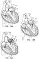
- FIGS. 12A, 12B, and 12C are schematic illustration of respective steps of the implantation of a docking element that is configured to define a spiral that extends from a mitral annulus of the subject until a roof of the subject's left atrium, and to become anchored within the left atrium by exerting an outward radial force upon a wall of the subject's left atrium, in accordance with some applications of the present invention.
- FIG. 1 is a schematic illustration of a prosthetic mitral valve apparatus 20 and a docking element 22 configured to facilitate anchoring of the prosthetic mitral valve apparatus to a subject's mitral valve.
- the prosthetic mitral valve apparatus is a stented valve that comprises a stented frame that is configured to support prosthetic valve leaflets 21 .
- the prosthetic mitral valve apparatus may be generally as described in WO 15/173794 to Spenser, which is incorporated herein by reference.
- the prosthetic mitral valve apparatus is typically implanted within the native mitral valve of a subject with a diseased native valve, and the prosthetic valve leaflets function such as to replace the functioning of the native valve leaflets.
- the prosthetic valve leaflets are configured to act as a one-way valve, whereby in their open positions with respect to one another the leaflets allow flow to pass through the prosthetic valve apparatus from the inlet (on the atrial side) to the outlet (on the ventricular side), whereas reverse flow is prevented due to collapsible slack portions of the valve leaflets collapsing inwardly to block the reverse flow.
- docking element 22 is implanted at the native mitral valve.
- the docking element includes a first, atrial component 24 , configured to be placed on the atrial side of the mitral valve, and at least one second, ventricular component 26 configured to be placed on a ventricular side of the mitral valve.
- the docking element includes two or more ventricular components 26 .
- the docking element itself becomes anchored to the mitral valve by the atrial and ventricular components being coupled to one another, e.g., via coupling elements 28 , such that tissue of the mitral valve, and/or tissue that surrounds the mitral valve, is disposed between the atrial and ventricular components.
- coupling elements 28 are coupled to ventricular components 26 prior to being inserted into the subject's body, and/or are integrally formed with the ventricular components. Coupling elements 28 are typically inserted into the left ventricle with ventricular components 26 . Subsequent to being inserted into the left ventricle, the coupling elements are coupled to atrial component 24 .
- the coupling elements may include portions that snap into the atrial component (or vice versa), such as to become coupled to the atrial component.
- the coupling elements and the atrial component may include threaded portions that become threadedly coupled to each other.
- coupling elements 28 are coupled to atrial component 24 , prior to being inserted into the subject's body, and/or are integrally formed with the atrial component. Coupling elements 28 are inserted into the left atrium with atrial component 24 . Subsequent to being inserted into the left atrium, the coupling elements are coupled to ventricular components 26 .
- the coupling elements may include portions that snap into the ventricular components (or vice versa), such as to become coupled to the ventricular components.
- the coupling elements and the ventricular components may include threaded portions that become threadedly coupled to each other.
- the atrial component and the ventricular components are coupled to each other via coupling elements 28 , prior to being inserted into the subject's body.
- the atrial component and ventricular components are inserted into the subject's heart, while coupled to one another, e.g., as described hereinbelow with reference to FIG. 7 .
- the docking element is implanted at the native mitral valve more than one week, or more than one month, before the implantation of the prosthetic mitral valve apparatus. Subsequent to the implantation of the docking element, and before the implantation of the prosthetic mitral valve apparatus, the anchoring of the docking element is typically strengthened by virtue of tissue ingrowth that occurs around the docking element.
- the docking element is implanted with respect to the native mitral valve, such that the native mitral valve leaflets are able to continue functioning in their normal manner subsequent to the implantation of the docking element, and prior to the implantation of the prosthetic mitral valve apparatus.
- the docking element and the prosthetic mitral valve apparatus are implanted at the native mitral valve in the same procedure as each other, with the docking element typically being implanted prior to the prosthetic mitral valve apparatus.
- FIGS. 2A, 29, and 2C are schematic illustrations of links 30 of atrial component 24 of the docking element 22 , in accordance with some applications of the present invention.
- the docking element includes atrial component 24 , configured to be placed on the atrial side of the mitral valve, and at least one ventricular component 26 configured to be placed on a ventricular side of the mitral valve.
- the atrial component includes a plurality of links, which are hingedly coupled to one another, as shown.
- the links are coupled to each other by flexible connecting elements 32 (e.g., as shown in FIGS. 2A and 2C ).
- the links and the flexible connecting elements are cut from a single piece of a material (such as, a single piece of a metal, a single piece of a metal alloy (such as nitinol), or a single piece of plastic), and the flexible connecting elements constitute locations at which the material is thinner than at the links, or locations at which notches are cut into the edges of the material, such that the links flex with respect to one another around those locations.
- the links are hingedly coupled to one another via a hinge mechanism, such as cylinders 34 that are disposed around a pin 36 , such that they pivot around the pin.
- Atrial component 24 is configured to be delivered to the subject's mitral valve, while disposed in a constrained configuration inside a delivery device (e.g., delivery, device 78 , shown in FIG. 4 ). Further typically, the atrial component defines a straight elongate shape while disposed in the constrained configuration.
- FIGS. 2A and 2C show the atrial component as configured while disposed inside a delivery device.
- FIGS. 2A and 2C show the atrial component in the absence of the delivery device, for illustrative purposes.
- the atrial component Upon being released from the delivery device, the atrial component is configured to loop around at least a portion of the mitral valve (and for some applications, to loop around the full circumference of the mitral valve), by the links flexing with respect to one another.
- the atrial component is shape set, such that, upon being released from the delivery device, the links flex with respect to one another automatically.
- the links are manually flexed with respect to one another such that the atrial component loops around at least a portion of the mitral valve.
- the ends of the atrial component are then coupled with respect to each other, e.g., using a cinching mechanism, and/or a connect-and-lock mechanism.
- the set of links are pre-formed as a ring, but are folded about two hinges 37 and 39 , such that respective portions 38 and 40 of the set of links are disposed alongside each other within the delivery device, e.g., as shown in FIG. 2C .
- the links form a ring by the centers of portions 38 and 40 moving away from each other, and the portions flexing about hinges 37 and 39 .
- FIGS. 3A, 3B, and 3C are schematic illustrations of ventricular components 26 of docking element 22 , in accordance with some applications of the present invention.
- the ventricular components include one or more anchors that are placed underneath the leaflets of the mitral valve and are coupled to atrial component 24 , as described hereinabove.
- the ventricular components are coupled to the atrial component via a commissure of the mitral valve.
- two ventricular components are used and respective ventricular components are coupled to the atrial component via respective mitral valve commissures.
- one or more holes are created (e.g., via piercing, or ablation) in one or both of the mitral valve leaflets and the ventricular components are coupled to the atrial component via the holes in the valve leaflet(s).
- three or more ventricular components are used. In such applications, the operator typically does not need to align any component of the docking element with commissures of the native mitral valve.
- the ventricular components are disposed inside a delivery device 42 in elongate configurations.
- the ventricular components Upon being released from the delivery device, the ventricular components are configured (e.g., automatically configured, due to shape setting of the ventricular components) to extend radially outwardly from the end of the delivery device, e.g., as shown in FIG. 3A .
- the ventricular components are configured to curve such as to conform with the shape of the mitral valve annulus.
- the ventricular components are wound into spirals, while disposed inside delivery device 42 .
- the ventricular components Upon being released from the delivery device, the ventricular components are configured (e.g., automatically configured, due to shape setting of the ventricular components) to extend radially outwardly from the end of the delivery device, by the spirals unwinding, e.g., as shown in FIG. 3B .
- the ventricular components are configured to form circular shapes when disposed underneath the mitral valve leaflets, the circular shapes extending into the subject's left ventricle.
- FIG. 4 is a schematic illustration of a guidewire 50 that is inserted into the subject's body via an insertion location 52 in a vein 54 (e.g., the femoral vein, as shown), and which exits that subject's body via an exit location 56 in an artery 58 (e.g., the femoral artery, as shown), in accordance with some applications of the present invention.
- a vein 54 e.g., the femoral vein, as shown
- an exit location 56 in an artery 58 e.g., the femoral artery, as shown
- the guidewire is advanced through vein 54 into the subject's vena cava 60 , and then, sequentially, through the vena cava into right atrium 62 , through the interatrial septum 64 , into left atrium 66 , through mitral valve 68 , through left ventricle 70 , aorta 72 , and then out of artery 58 .
- a snare 76 is used to grasp a distal portion of the guidewire.
- Atrial component 24 of docking element 22 is advanced to the subject's left atrium by advancing the atrial component over the guidewire from insertion location 52 in vein 54 to the left atrium.
- a delivery device 78 (such as a catheter, as shown) is advanced over the guidewire from insertion location 52 in vein 54 to the left atrium, and the atrial component of the docking element is delivered to the left atrium over the guidewire and inside the delivery device.
- ventricular component 26 is advanced to the subject's left ventricle by advancing the ventricular component over the guidewire, from exit location 56 in artery 58 to the left ventricle.
- an additional delivery device (not shown) is advanced over the guidewire from exit location 56 in artery 58 to the left ventricle, and the ventricular component of the docking element is delivered to the left ventricle over the guidewire and inside the delivery device.
- FIG. 5 is a schematic illustration of two guidewires 50 and 80 that are advanced through a subject's body in the manner described with reference to FIG. 4 , and which pass through respective commissures 82 and 84 of the subject's mitral valve 68 , in accordance with some applications of the present invention.
- FIG. 6 is a schematic illustration of a catheter 86 defining at least two channels 88 and 90 therethrough, in order to facilitate the insertion of two guidewires through respective commissures 82 and 84 of the subject's mitral valve 68 , in accordance with some applications of the present invention.
- first guidewire 50 is advanced in the general manner described hereinabove with reference to FIG. 4 . That is to say that the guidewire is inserted via insertion location 52 in vein 54 and is then advanced such that a distal end of the guidewire exits the subject's body via exit location 56 in artery 58 , by passing the guidewire, sequentially, through the subject's vena cava 60 , right atrium 62 , interatrial septum 64 , left atrium 66 , mitral valve 68 , left ventricle 70 , and aorta 72 . Subsequently, first channel 88 of catheter 86 is advanced over first guidewire 50 from insertion location 52 in vein 54 to exit location 56 in artery 58 .
- the second guidewire is advanced through channel 90 of catheter 86 from insertion location 52 in vein 54 to exit location 56 in artery 58 .
- the two guidewires pass from insertion location 52 in vein 54 to exit location 56 in artery 58 in parallel to one another, but without becoming twisted with one another.
- more than two guidewires are inserted in parallel with one another using the above-described techniques, mutatis mutandis.
- the proximal ends of guidewires 50 and 80 are inserted into respective locations within atrial component 24 .
- the atrial component is then inserted via insertion location 52 in vein 54 (typically, via a delivery device, such as a catheter) and is guided by the guidewires to atrium 66 .
- guidewires 50 and 80 position the respective locations within the atrial component at predesignated positions with respect to the subject's mitral valve.
- the guidewires may guide portions of the atrial component to which coupling elements 28 are coupled (or to which coupling elements 28 are configured to become coupled) to commissures of the mitral valve or to holes that have been created in the mitral valve leaflets.
- a first ventricular component 26 is advanced over a first one of the guidewires from exit location 56 in artery 58 to a first one of the commissures of the mitral valve, and a second ventricular component 26 is advanced over a second one of the guidewires from exit location 56 in artery 58 to a second one of the commissures of the mitral valve.
- the first and second ventricular components are then coupled to atrial component 24 , as described hereinabove.
- the ventricular components are advanced to the ventricle while disposed inside a delivery device, and the atrial component is advanced to the left atrium while disposed inside a delivery device.
- the techniques described herein for advancing a first component of a mitral valve implant to a ventricular side of the subject's mitral valve, by advancing the first component over a guidewire from an exit location in an artery, and advancing a second component of the mitral valve implant to an atrial side of the subject's mitral valve, by advancing the second component over the guidewire from an insertion location in a vein are applied to mitral valve implants other than docking element 22 , mutatis mutandis.
- FIG. 7 is a schematic illustration of docking element 22 , in accordance with some applications of the present invention.
- atrial component 24 is coupled to a stabilizing frame 92 , for example, by, means of fabric (e.g., PET, PTFE, and/or nylon) and/or sutures.
- the stabilizing frame is a stent-like structure, the stabilizing frame comprising struts that define cells.
- the stabilizing frame is at least partially flexible.
- the stabilizing frame is configured to expand such as to contact the walls of the atrium, and to thereby anchor the atrial component on the atrial side of the mitral valve annulus.
- the atrial component is a flexible ring made of fabric (e.g., PET, PTFE, and/or nylon) that is coupled to the stabilizing frame.
- the stabilizing frame is covered with a material, such as PET, PTFE, and/or nylon.
- the stabilizing frame is coupled to the tissue of the atrium, via tissue-coupling elements 94 , such as, sutures or clips.
- the ventricular components include substantially straight bars, and the bars are coupled to atrial component 24 via coupling elements 28 that are flexible (e.g., strings or wires).
- the ventricular components are inserted into the subject's left atrium via a delivery device, while coupled to the atrial component.
- the ventricular components are disposed within a lumen of the delivery device such that the longitudinal axes of the ventricular components are parallel to the longitudinal axis of the lumen.
- the ventricular components are passed into the subject's left ventricle (e.g., by being passed through commissures of the mitral valve, or by passed through holes that have been created within the mitral valve leaflets), while longitudinal axes of the ventricular components are parallel to the longitudinal axes of coupling elements 28 . Subsequent to passing into the subject's left ventricle, the ventricular components rotate, such that longitudinal axes of the ventricular components are perpendicular to the longitudinal axes of coupling elements 28 , The ventricular components are thereby prevented from passing back through the mitral valve and into the left atrium.
- docking element 22 is configured to facilitate anchoring of prosthetic mitral valve apparatus 20 to the subject's mitral valve.
- the docking element occupies some of the area defined by the native mitral valve annulus. Therefore, for some applications, prosthetic mitral valve apparatus is coupled to the subject's mitral valve, prosthetic valve leaflets 21 of the prosthetic mitral valve apparatus spanning a diameter that is less than the measured diameter of the native mitral valve annulus (the diameter of the native mitral valve annulus typically being measured using a mitral measuring ring, and/or using imaging methods, such as ultrasound).
- the ratio of (a) the diameter that is spanned by the prosthetic valve leaflets to (b) the diameter of the native mitral valve annulus may be less than 5:6.
- the diameter that is spanned by the prosthetic valve leaflets may be less than 25 mm.
- one or more advantages of the prosthetic valve leaflets spanning a diameter that is less than that of the native mitral valve annulus, relative to using a prosthetic valve apparatus having prosthetic valve leaflets that span a greater diameter may include: the prosthetic valve apparatus having a lower crimped profile, there being less foreign matter inside the subject's heart, lower forces being exerted on the prosthetic valve leaflets, better anchoring of the prosthetic valve apparatus, less interference with the native anatomy, and/or better preservation of a clear left ventricular outflow tract.
- prosthetic mitral valve apparatus having prosthetic valve leaflets spanning a diameter that is less than that of the native mitral valve annulus may be used for a different reason.
- Atrial component 24 and/or ventricular components 26 of docking element 22 are made from a super elastic, shape memory material such as nitinol alloy, which is shape set to define the shapes described hereinabove.
- a delivery device e.g., delivery device 78 , FIG. 4
- the components automatically assume the above-described shapes.
- atrial component 24 and/or ventricular components 26 of docking element 22 are configured to undergo a phase change as they approach body temperature.
- a polymer material is injected into a base material that forms the atrial component 24 and/or ventricular components 26 of docking element 22 , the material being configured to impart desired stiffness, flexibility, resilience, or other properties.
- FIG. 8A is a schematic illustration of a docking element 100 configured to facilitate anchoring of prosthetic mitral valve apparatus to a subject's mitral valve, in accordance with some alternative applications of the present invention.
- Docking element 100 is generally similar to docking element 22 described hereinabove, except for the differences described hereinbelow.
- docking element 100 is configured to anchor prosthetic mitral valve apparatus 20 to native mitral valve 68 , e.g. using generally similar techniques to those described hereinabove.
- FIG. 8B is a schematic illustration of docking element 100 disposed, in its entirety, within a subject's left atrium, in accordance with some applications of the present invention.
- docking element 100 includes a ring 102 and a frame 104 extending from the ring, Docking element 100 is typically deployed within the subject's left atrium 66 , such that (a) no portion of the docking element extends through the subject's native mitral valve, (b) the ring is disposed at a mitral valve annulus 106 of the subject, and (c) the frame extends from the subject's mitral valve annulus until at least 30 percent of the height of the left atrium, e.g., more than 50 percent of the height of the left atrium.
- a height H of the frame is at least 15 mm (e.g., at least 20 mm), and/or less than 40 mm (e.g., less than 35 mm), e.g., between 15 and 40 mm, or between 20 and 35 mm.
- the frame when disposed inside the left atrium, the frame typically extends from the subject's mitral valve annulus until a height from the mitral valve annulus of at least 15 mm (e.g., at least 20 mm), and/or less than 40 mm (e.g., less than 35 mm), e.g., between 15 and 40 mm, or between 20 and 35 mm.
- the docking element becomes anchored to the subject's heart by virtue of (a) outward radial force exerted by ring 102 upon mitral valve annulus 106 , (h) outward radial force exerted by frame 104 upon the wall of left atrium 66 , (c) tissue ingrowth from mitral valve annulus 106 to ring 102 (and/or components coupled thereto), and/or (d) tissue ingrowth from the inner wall of the left atrium to the frame (and/or components coupled thereto).
- frame 104 of docking element is made of a super-elastic, shape-memory material, such as nitinol alloy.
- the frame is typically shape set to define a shape that conforms with the shape of the atrium, but that is oversized with respect to the left atrium, such that the frame is configured to exert an outward radial force against the inner wall of the left atrium.
- a fabric layer 108 is disposed around the outside of frame 104 and/or ring 102 .
- the fabric layer may be made of a fabric such as PET, PTFE, and/or nylon, and may be coupled to the outside of the frame and/or the ring using stitches.
- the fabric of the fabric layer is configured to facilitate (a) tissue ingrowth to the frame, such that the frame becomes coupled to the inner wall of the left atrium, and/or (b) tissue ingrowth to the ring, such that the ring becomes coupled to the mitral valve annulus.
- tissue-ingrowth elements 110 are coupled to the fabric layer to encourage tissue ingrowth.
- tissue-ingrowth elements may include hooks or loops (e.g., similar to those used in hook-and-loop fasteners), barbs, clips, pins, etc.
- the tissue-ingrowth elements are configured to nib against the wall of the left atrium and to encourage tissue growth into the fabric of the fabric layer.
- the tissue-ingrowth elements include fabric sheets 111 , to which fibers 113 hook shaped fibers, as shown) are coupled in a perpendicular arrangement with respect to the fabric sheets.
- the fibers are coupled directly to fabric layer 108 .
- the fibers are configured to rub against the wall of the left atrium and to encourage tissue growth into the fibers and the fabric sheets.
- the tissue-ingrowth elements are coupled to the fabric at a location that is configured to be disposed at or in a vicinity of (e.g., within 5 mm of) the mitral valve annulus.
- the tissue-ingrowth elements define a 3D structure (e.g., as described hereinabove) that is configured to increase the contact area between the tissue and the frame and to serve as a scaffold for tissue to grow into.
- docking element 100 is implanted at the native mitral valve more than one week, or more than one month, before the implantation of the prosthetic mitral valve apparatus.
- the anchoring of the docking element is typically strengthened by virtue of tissue ingrowth that occurs around the docking element, e.g., as described hereinabove.
- the native mitral valve leaflets are able to continue functioning in their normal manner subsequent to the implantation of the docking element, and prior to the implantation of the prosthetic mitral valve apparatus.
- the above-described, two-stage implantation procedure is somewhat analogous to a valve-in-valve procedure, whereby a new prosthetic valve is implanted inside a previously-implanted prosthetic valve.
- the new valve typically becomes anchored within the previously-implanted valve, and the previously-implanted valve is strongly anchored to the native mitral valve, by virtue of tissue ingrowth with respect to the previously-implanted valve, as well as mechanical force exerted upon the heart by the previously-implanted prosthetic valve.
- docking element 100 is implanted and is allowed to become anchored to the subject's heart by virtue of tissue ingrowth with respect to the docking element, as well as mechanical force exerted upon the heart by the docking element. Subsequently, once the docking element is anchored within the subject's heart, prosthetic mitral valve apparatus is anchored to the docking element.
- docking element 100 and/or prosthetic mitral valve apparatus 20 is delivered to the subject's heart transapically, transseptally, and/or transaortically.
- the size of the delivery device may be smaller than if the prosthetic mitral valve apparatus was to be delivered together with the docking element, ceteris paribus.
- reducing the size of the delivery device that is required, in the above-described manner facilitates transeptal insertion of the docking element and/or the prosthetic mitral valve apparatus.
- the prosthetic mitral valve apparatus becomes anchored within ring 102 of docking element 100 .
- the inner diameter of ring 102 is more than 20 mm.
- the inner diameter of ring 102 is smaller than the inner diameter of native mitral valve annulus 106 .
- the inner diameter of ring 102 may be more than less than 30 mm, e.g., less than 28 mm.
- the ring acts as an artificial mitral valve annulus that is smaller than the native mitral valve annulus.
- the prosthetic mitral valve is configured to have a diameter that is less than the native mitral valve.
- a ratio of the diameter of the prosthetic mitral valve to that of the native mitral valve may be less than 7:8, or less than 3:4.
- using a prosthetic mitral valve that has a diameter that is less than the native mitral valve facilitates using a delivery device that is smaller than that which would be required by a prosthetic valve having the same diameter as the native mitral valve, ceteris paribus.
- the prosthetic mitral valve has a diameter that is less than that of the native mitral valve, and has an effective orifice area of 1.8 cm ⁇ circumflex over ( ) ⁇ 2 or more, which is typically sufficiently large for the heart to function healthily, in the majority of patients.
- the docking element and the prosthetic mitral valve apparatus are implanted above the native mitral valve in the same procedure as each other, with the docking element typically being implanted prior to the prosthetic mitral valve apparatus.
- the prosthetic mitral valve apparatus when the prosthetic mitral valve apparatus is initially implanted, the prosthetic mitral valve leaflets are held open, for example, using sutures.
- the prosthetic mitral valve leaflets are maintained in the open state (e.g., using the sutures) for a period of more than more than one week, or more than one month, during which period the docking element becomes anchored to the subject's heart by virtue of tissue ingrowth, in accordance with the techniques described hereinabove.
- the docking element is not required to bear the load of blood impacting the prosthetic valve leaflets. Subsequently, the element that is keeping the prosthetic valve leaflets open (e.g., the sutures) is removed, such that the prosthetic valve leaflets begin functioning.
- the element that is keeping the prosthetic valve leaflets open e.g., the sutures
- frame 104 typically defines openings 112 at an upper portion 114 of the frame. Further typically, fabric layer 108 defines holes 116 therethrough at the upper portion of the frame. For some applications, opening 112 and holes 116 are configured to allow blood flow therethrough, such that blood flow from pulmonary veins 118 into the left atrium is not occluded.
- FIG. 9 is a schematic illustration of docking element 100 disposed, in its entirety, within a subject's left atrium, the docking element being configured to facilitate anchoring of prosthetic mitral valve apparatus to a subject's mitral valve, in accordance with some applications of the present invention.
- Docking element 100 as shown in FIG. 9 is generally similar to docking element 100 as shown in FIGS. 8A and 8B , except for differences described hereinbelow.
- frame 104 of the docking element is shaped to define cells, which are distributed throughout the structure of the frame.
- FIG. 9 is a schematic illustration of docking element 100 disposed, in its entirety, within a subject's left atrium, the docking element being configured to facilitate anchoring of prosthetic mitral valve apparatus to a subject's mitral valve, in accordance with some applications of the present invention.
- Docking element 100 as shown in FIG. 9 is generally similar to docking element 100 as shown in FIGS. 8A and 8B , except for differences described hereinbelow.
- frame 104 of the docking element is shaped to define a plurality of cells 120 that define ring 102 .
- ring 102 is not necessarily shaped as a ring, but rather is a zig-zagged structure that comprises the edges of cells 120 .
- the frame of the docking elements described herein includes struts and the ring of the docking element is defined by some of the struts of the frame.
- the frame is configured to extend to the top portion of the left atrium via a plurality of elongate elements 122 that extend from cells 120 .
- the structure of the frame is configured such that at junctions of the pulmonary veins with the left atrium (or in a vicinity of such junctions (e.g., within 2 mm of such junctions), the frame does not contact tissue of the heart, such that blood flow from the pulmonary veins into the left atrium is not occluded.
- docking element as shown in FIG. 9 is covered with a fabric layer, and/or tissue ingrowth elements, which are typically generally as described hereinabove with reference to FIGS. 8A and 8B , mutatis mutandis.
- FIG. 10 is a schematic illustration of docking element 100 disposed, in its entirety, within a subject's left atrium, the docking element being configured to facilitate anchoring of prosthetic mitral valve apparatus to a subject's mitral valve, in accordance with some applications of the present invention.
- Docking element 100 as shown in FIG. 10 is generally similar to docking element 100 as shown in FIGS. 8A and 8B , except for differences described hereinbelow.
- frame 104 of the docking element is configured to radially expand against the walls of the left atrium along the length of the frame.
- FIG. 10 is a schematic illustration of docking element 100 disposed, in its entirety, within a subject's left atrium, the docking element being configured to facilitate anchoring of prosthetic mitral valve apparatus to a subject's mitral valve, in accordance with some applications of the present invention.
- Docking element 100 as shown in FIG. 10 is generally similar to docking element 100 as shown in FIGS. 8A and 8B , except for differences described hereinbelow.
- frame 104 of the docking element is shaped to define an upper portion 130 , a lower portion 132 , and an intermediate portion 134 disposed between the upper and lower portions.
- the upper and lower portions are configured to expand against the inner wall of the left atrium.
- lower portion 132 defines ring 102 , which is configured to exert a radial force upon the mitral valve annulus.
- ring 102 is not necessarily shaped as a ring, but rather is a zig-zagged structure that comprises the edges of cells lower portion 132 .
- the frame of the docking elements described herein includes struts and the ring of the docking element is defined by some of the struts of the frame.)
- the intermediate portion is configured to be narrower than the upper and lower portions, and not to contact the inner wall of the left atrium.
- the upper and lower portions are inverted with respect to the intermediate portion.
- the structure of the frame is configured such that at junctions of the pulmonary veins with the left atrium (or in a vicinity of such junctions (e.g., within 2 mm of such junctions), the frame does not contact tissue of the heart, such that blood flow from the pulmonary veins into the left atrium is not occluded.
- docking element as shown in FIG. 10 is covered with a fabric layer, and/or tissue ingrowth elements, which are typically generally as described hereinabove with reference to FIGS. 8A and 8B , mutatis mutandis.
- only the upper and lower portions of the frame are covered with the fabric layer, and/or tissue ingrowth elements, and the intermediate portion is uncovered.
- the frame is configured to only apply a relatively low pressure to the inner wall of the left atrium, such that the frame conforms to the shape of the left atrium, rather than forcing the atrium to deform.
- the frame may be configured to apply a relatively low pressure to the inner wall of the left atrium, such that the frame conforms to the shape of the left atrium, rather than forcing the atrium to deform.
- the frame allows the natural compliance of the inner wall of the left atrium to be substantially, maintained.
- frame 104 as shown in FIGS.
- 9 and 10 is able to be radially constrained (during insertion of the frame to the heart) to a smaller diameter than a frame as shown in FIGS. 8A and 8B , since the frame comprises less of the shape-memory material than the configuration shown in FIGS. 8A and 8B , mutatis mutant/is.
- FIG. 11A is a schematic illustration of a docking element 140 configured to facilitate anchoring of prosthetic mitral valve apparatus to a subject's mitral valve by a portion of the docking element becoming anchored to a left atrial appendage 142 of the subject, in accordance with some alternative applications of the present invention.
- FIG. 11B is a schematic illustration of docking element 140 disposed, in its entirety, within subject's left atrium with a left-atrial-appendage anchor 144 of the docking element being anchored to left atrial appendage 142 , in accordance with some applications of the present invention.
- docking element 140 includes a frame 146 , a ring 148 , and left-atrial-appendage anchor 144 .
- ring 148 is defined by struts of frame 146 .
- the struts that define the ring are thicker than other struts of the frame.
- the prosthetic mitral valve apparatus is configured to become coupled to the docking element, by the prosthetic mitral valve apparatus radially expanding against ring 148 .
- ring 148 typically bears much of the load of the forces that are exerted upon the prosthetic mitral valve apparatus.
- the ring is configured to bear this load at least partially by virtue of the struts that define the ring being thicker than other struts of the frame.
- the ring in its deployed state inside the left atrium, the ring is disposed transversely with respect to the frame, such that a plane defined by the ring is substantially parallel to the longitudinal axis of the frame.
- the docking element is placed into left atrium 66 , via interatrial septum 64 (shown in FIG. 4 ), by advancing the docking element, along its longitudinal axis, in a lateral direction with respect to the subject's left atrium. Subsequently, without rotating the docking element, the docking element is deployed within the subject's left atrium, such that ring 148 is disposed at the native mitral annulus, and is disposed transversely with respect to the frame.
- the longitudinal axis of the frame is substantially parallel to a plane defined by the subject's mitral valve annulus.
- the docking element does not need to be substantially rotated with respect to the left atrium between being transseptally inserted into the left atrium, and being deployed within the left atrium.
- the ring was disposed at a longitudinal end of the frame such that the plane defined by the ring was substantially perpendicular to the longitudinal axis of the frame, this would make it challenging to insert the docking element transseptally. This is because the frame would need to be rotated (approximately 90 degrees relative to the interatrial septum) and released from the delivery device within the relatively small volume that is defined by the left atrium.
- docking element 140 is covered with a fabric layer, and/or tissue ingrowth elements, which are typically generally as described hereinabove with reference to FIGS. 8A and 8B , mutatis mutandis. As described hereinabove with reference to docking element 100 of FIGS.
- docking element 140 becomes anchored to the subject's heart by virtue of (a) outward radial force exerted by ring 148 upon mitral valve annulus 106 , (h) outward radial force exerted by frame 146 upon the wall of left atrium 66 , (c) tissue ingrowth from mitral valve annulus 106 to ring 148 (and/or components coupled thereto), and/or (d) tissue ingrowth from the left atrium wall to the frame (and/or components coupled thereto).
- docking element 140 additionally includes left-atrial-appendage anchor 144 which is configured to be inserted into the left atrial appendage, and to become anchored within the left atrial appendage, such as to further anchor the docking element with respect to the subject's heart.
- left atrial appendage 142 is shown in FIG. 11B as being to the right of the left atrium, when looking at the page, and frame 146 is shown as being disposed such that the longitudinal axis of the frame goes from the left to the right of the page.
- the left atrial appendage would come at least partially out of the page.
- the longitudinal axis of the frame would extend at least partially in the direction from behind the page to in front of the page.
- FIGS. 11A and 11B show docking element 140 as including (a) left-atrial-appendage anchor 144 , and (b) ring 148 that is disposed transversely with respect to the frame, the scope of the present invention includes a docking element that includes one of components (a) and (b), even in the absence of the other component. It is further noted that features of docking element 100 described hereinabove with reference to FIGS. 8A and 8B may be combined with features of docking element 140 , described with reference to FIGS. 11A and 11B .
- the height of frame 146 of docking element 140 may be at least 15 mm (e.g., at least 20 mm), and/or less than 40 mm (e.g., less than 35 mm), e.g., between 15 and 40 mm, or between 20 and 35 mm.
- the frame when disposed inside the left atrium, the frame typically extends from the subject's mitral valve annulus until a height from the mitral valve annulus of at least 15 mm (e.g., at least 20 mm), and/or less than 40 mm (e.g., less than 35 mm), e.g., between 15 and 40 mm, or between 20 and 35 mm.
- a height from the mitral valve annulus of at least 15 mm e.g., at least 20 mm
- 40 mm e.g., less than 35 mm
- the structure of frame 146 is configured such that, at junctions of the pulmonary veins with the left atrium (and/or in a vicinity of such junctions (e.g., within 2 mm of such junctions), the frame does not contact tissue of the heart (e.g., because the cells are open and are not covered with fabric, such that blood can flow through the cells), In this manner, blood flow from the pulmonary veins into the left atrium is not occluded.
- FIGS. 12 A, 12 B, and 12 C are schematic illustrations of respective steps of the implantation of a docking element 150 that is configured to define a spiral that extends from the mitral annulus until a roof 152 of the subject's left atrium 66 , and becomes anchored within the left atrium by exerting an outward radial force upon the inner wall of the subject's left atrium, in accordance with some applications of the present invention.
- docking element 150 is configured to anchor prosthetic mitral valve apparatus 20 above the native mitral valve 68 , e.g. using generally similar techniques to those described hereinabove.
- Docking element 150 is typically made of a super-elastic, shape-memory material a shape-memory alloy, such as nitinol), which is shape set to define a spiral shape that conforms with a shape of the left atrium, but that is oversized with respect to the left atrium, such that the spiral is configured to exert an outward radial force against the inner wall of the left atrium.
- the docking element is disposed in an elongate configuration inside a delivery device 154 .
- the delivery device is inserted into the left atrium transseptally, as shown in FIGS. 12A-C .
- the delivery device is inserted into the left atrium via a different route, e.g., transapically, or transaortically.
- the docking element is advanced with respect to the delivery device. Further typically, the advancement of the docking element causes the docking element to assume a spiral shape, as shown in the transition from FIG. 12A to FIG. 12B , and from FIG. 12B to FIG. 12C .
- the apparatus and methods described herein are performed with respect to a tricuspid valve, and/or a different valve in a subject's body, mutatis mutandis.
- Inventive concept 1 A method for treating a subject with a diseased mitral valve, the method comprising:
- advancing the first component of the mitral valve implant to the ventricular side of the subject's mitral valve comprises advancing a ventricular component of a docking element to the ventricular side of the subject's mitral valve;
- advancing the second component of the mitral valve implant to the atrial side of the subject's mitral valve comprises advancing an atrial component of the docking element to the atrial side of the subject's mitral valve;
- anchoring the mitral valve implant to the subject's mitral valve by coupling the first and second components to each other comprises anchoring the docking element to the subject's mitral valve, to thereby facilitate anchoring of a prosthetic mitral valve apparatus to the subject's mitral valve
- inserting at least one guidewire into the subject's body subject via the insertion location in the subject's vein comprises inserting two or more guidewires into the subject's body subject via the insertion location in the subject's vein;
- advancing the at least one guidewire such that the distal end of the guidewire exits the subject's body via the exit location in the subject's artery comprises advancing the two or more guidewires such that distal ends of the two or more guidewires exit the subject's body via the exit location in the subject's artery;
- advancing the first component of the mitral valve implant to the ventricular side of the subject's mitral valve by advancing the first component over the guidewire from the exit location in the artery comprises advancing two or more first components of the mitral valve implant to the ventricular side of the subject's mitral valve, by advancing the first components over respective guidewires of the two or more guidewires from the exit location in the artery.
- Inventive concept 4 The method according to inventive concept 3, wherein advancing the two or more guidewires such that distal ends of the two or more guidewires exit the subject's body via the exit location in the subject's artery comprises advancing the two or more guidewires via respective lumens of a catheter.
- Inventive concept 5. The method according to inventive concept 3, wherein advancing the second component of the mitral valve implant to the atrial side of the subject's mitral valve by advancing the second component over the guidewire from the insertion location in the vein comprises using respective guidewires to position respective locations within the second component at predesignated positions with respect to the subject's mitral valve.
- Apparatus for treating a subject with a diseased mitral valve comprising:
- a mitral valve implant comprising:
- At least one guidewire configured to be advanced, from an insertion location in a vein of a subject to an exit location in an artery of the subject, by passing sequentially, through a vena cava of the subject, a right atrium of the subject, an interatrial septum of the subject, a left atrium of the subject, the mitral valve, a left ventricle of the subject, and an aorta of the subject,
- the left atrial component is configured to be inserted into the subject's left atrium by being advanced over the guidewire from the insertion location in the subject's vein, and the left ventricular component is configured to be advanced to the left ventricle by being advanced from the exit location in the subjects artery.
- the at least one guidewire comprises two or more guidewires configured to be advanced, in parallel to one another, from the insertion location in the subject's vein to the exit location in the subject's artery;
- the left ventricular component comprises two or more left ventricular components configured to be advanced to the left ventricle by being advanced from the exit location in the artery over respective guidewires of the two or more guidewires.
- Inventive concept 10 The apparatus according to inventive concept 9, further comprising a catheter that defines two or more lumens that are parallel to one another, wherein the two or more guidewires are configured to be advanced, in parallel with one another, via respective lumens of the catheter.
- Inventive concept 11 The apparatus according to inventive concept 9, wherein the guidewires are configured to position respective locations within the left atrial component at predesignated positions with respect to the subject's mitral valve.
- Inventive concept 12 Apparatus for use with prosthetic mitral valve apparatus for treating a subject with a diseased mitral valve, the apparatus comprising:
- a docking element configured to become anchored to the subjects mitral valve, and to thereby facilitate anchoring of the prosthetic mitral valve apparatus to the subject's mitral valve, the docking element comprising:
- a docking element comprising:
- a prosthetic mitral valve apparatus configured to be placed at least partially inside the docking element, and to become anchored to the docking element, at least partially by radially expanding against the ring.
- Inventive concept 23 The apparatus according to inventive concept 22, wherein the frame comprises a plurality of struts, and wherein the ring is defined by at least some of the struts of the frame.
- Inventive concept 24 The apparatus according to inventive concept 22, wherein the docking element is configured to be deployed within the subject's left atrium, such that the ring is disposed at a mitral valve annulus of the subject, and such that the longitudinal axis of the frame is substantially parallel to the subject's native mitral valve annulus.
- Inventive concept 25 The apparatus according to inventive concept 22, wherein the docking element is configured to become deployed within the subject's left atrium, such that no portion of the docking element extends through the subject's native mitral valve.
- Inventive concept 26 The apparatus according to any one of inventive concepts 22-25, wherein the frame comprises tissue-ingrowth elements coupled thereto, the tissue-ingrowth elements being configured to encourage tissue ingrowth with respect to the frame.
- Inventive concept 27 The apparatus according to any one of inventive concepts 22-25, wherein the frame comprises tissue-ingrowth elements coupled thereto, the tissue-ingrowth elements being configured to encourage tissue ingrowth with respect to the frame.
- tissue-ingrowth elements comprise fabric sheets with fibers disposed thereon, the fibers being disposed substantially perpendicularly with respect to the fabric sheets.
- inventive concept 28 The apparatus according to any one of inventive concepts 22-25, further comprising a fabric layer that is configured to cover the frame.
- inventive concept 29 The apparatus according to inventive concept 28, wherein the fabric layer defines holes therethrough, the holes defined by the fabric layer being configured to be disposed in a vicinity of junctions of the left atrium with pulmonary veins of the subject, when the docking element is in an implanted state within the subject's left atrium.
- Inventive concept 30 A method for treating a subject with a diseased mitral valve, the method comprising:
- the docking element including a ring
- the docking element within the subject's left atrium, such that at least a portion of the docking element is disposed within a left atrial appendage of the subject, and such that the ring is disposed at a mitral valve annulus of the subject;
- a docking element configured to be inserted into a left atrium of the subject, the docking element comprising:
- a prosthetic mitral valve apparatus configured to be placed at least partially inside the docking element, and to become anchored to the docking element, at least partially by radially expanding against the ring.
- Inventive concept 41 The apparatus according to inventive concept 40, wherein the docking element comprises a frame that comprises a plurality of struts, and wherein the ring is defined by at least some of the struts of the frame.
- Inventive concept 42 The apparatus according to inventive concept 40, wherein the docking element comprises a frame, and a plane defined by the ring is parallel to a longitudinal axis of the frame.
- Inventive concept 43 The apparatus according to any one of inventive concepts 40-42, wherein the docking element comprises a frame having tissue-ingrowth elements coupled thereto, the tissue-ingrowth elements being configured to encourage tissue ingrowth with respect to the frame.
- tissue-ingrowth elements comprise fabric sheets with fibers disposed thereon, the fibers being disposed substantially perpendicularly with respect to the fabric sheets.
- Inventive concept 45 The apparatus according to any one of inventive concepts 40-42, wherein the docking element comprises a frame and a fabric layer disposed upon the frame.
- Inventive concept 46 The apparatus according to any one of inventive concepts 40-42, wherein the docking element comprises a frame and a fabric layer disposed upon the frame.
- inventive concept 45 wherein the fabric layer defines holes therethrough, the holes defined by the fabric layer being configured to be disposed in a vicinity of junctions of the left atrium with pulmonary veins of the subject, when the docking element is in a deployed state within the subject's left atrium.
- inventive concept 47 A method for treating a subject with a diseased mitral valve, the method comprising:
- the docking element within the subject's left atrium, such that the docking element defines a spiral that extends from a mitral annulus of the subject until a roof of the subject's left atrium, and becomes anchored within the left atrium by exerting an outward radial force upon a wall of the subject's left atrium;
- a docking element configured to be placed inside a left atrium of the subject, the docking element being configured to define a spiral that extends from a mitral annulus of the subject until a roof of the subject's left atrium, and to become anchored within the left atrium by exerting an outward radial force upon a wall of the subject's left atrium;
- a prosthetic mitral valve apparatus configured to be placed at least partially inside the docking element, and to become anchored to the docking element, at least partially by radially expanding against a portion of the spiral that is disposed at the subject's mitral annulus.
- a method for treating a subject with a diseased mitral valve comprising:
- Inventive concept 50 The method according to inventive concept 49, wherein holding open the prosthetic mitral valve leaflets comprises holding open the prosthetic mitral valve leaflets using sutures, and wherein allowing the prosthetic mitral valve leaflets to close comprises removing the sutures.
Abstract
Description
-
- a ring configured to be implanted at a mitral valve annulus of the subject;
- a frame extending upwardly from the ring, a height of the frame being at least 15 mm, the frame being configured to radially expand against an inner wall of the subject's left atrium; and
-
- subsequent to the ingrowth of the tissue of the left atrium to the docking element having occurred, to be placed at least partially inside the docking element, and to become anchored to the docking element, at least partially by radially expanding against the ring.
-
- inserting a prosthetic mitral valve apparatus to inside the ring; and
- causing the prosthetic mitral valve apparatus to radially expand against the ring, such that the prosthetic mitral valve apparatus is anchored within the ring.
-
- inserting at least one guidewire into a body of a subject via an insertion location in a vein of a subject;
- advancing e at least one guidewire such that a distal end of the guidewire exits the subject's body via an exit location in an artery of the subject, by passing the guidewire, sequentially, through a vena cava of the subject, a right atrium of the subject, an interatrial septum of the subject, a left atrium of the subject, the mitral valve, a left ventricle of the subject, and an aorta of the subject;
- advancing a first component of a mitral valve implant to a ventricular side of the subject's mitral valve, by advancing the first component over the guidewire from the exit location in the artery;
- advancing a second component of the mitral valve implant to an atrial side of the subject's mitral valve, by advancing the second component over the guidewire from the insertion location in the vein; and
- anchoring the mitral valve implant to the subject's mitral valve by coupling the first and second components to each other.
Inventive concept 2. The method according to inventive concept 1, wherein:
Inventive concept 5. The method according to
Inventive concept 6. Apparatus for treating a subject with a diseased mitral valve, comprising:
-
- a left atrial component configured to be inserted into a left atrium of the subject via a vena cava of the subject; and
- a left ventricular component configured to be inserted into a left ventricle of the subject via an aorta of the subject,
- the left atrial component and left ventricular component being configured to become anchored to the mitral valve by being coupled to one another.
Inventive concept 7. The apparatus according to inventive concept 6, wherein the apparatus is for use with a prosthetic mitral valve apparatus, and the mitral valve implant comprises a docking element configured to become anchored to the subject's mitral valve, and to thereby facilitate anchoring of the prosthetic mitral valve apparatus to the subject's mitral valve.
Inventive concept 8. The apparatus according to inventive concept 6 or inventive concept 7,
Inventive concept 11. The apparatus according to inventive concept 9, wherein the guidewires are configured to position respective locations within the left atrial component at predesignated positions with respect to the subject's mitral valve.
Inventive concept 12. Apparatus for use with prosthetic mitral valve apparatus for treating a subject with a diseased mitral valve, the apparatus comprising:
-
- an atrial component that comprises a plurality of links that are hingedly coupled to one another, the atrial component being configured:
- to be delivered to the subject's mitral valve, while disposed in a constrained configuration inside the delivery device, the plurality of links forming a straight elongate shape while disposed in the constrained configuration, and
- upon being released from the delivery device, to loop around at least a portion of the mitral valve, by the links flexing with respect to one another; and
- one or more ventricular components that are configured to be placed underneath leaflets of the mitral valve and to be coupled to the atrial component.
Inventive concept 13. A method for treating a subject with a diseased mitral valve, the method comprising:
- an atrial component that comprises a plurality of links that are hingedly coupled to one another, the atrial component being configured:
-
- inserting a prosthetic mitral valve apparatus to inside the ring; and
- deploying the prosthetic mitral valve apparatus within the ring, such that the prosthetic mitral valve is anchored within the ring.
Inventive concept 14. The method according to inventive concept 13, wherein deploying the docking element within the subject's left atrium comprises deploying the docking element within the subject's left atrium such that the docking element does not contact tissue of the left atrium in a vicinity of junctions of the left atrium with pulmonary veins of the subject.
Inventive concept 15. The method according to inventive concept 13, wherein advancing the docking element in the lateral direction with respect to the left atrium comprises advancing the docking element in a direction that is parallel to a longitudinal axis of a frame of the docking element, and wherein deploying the docking element within the subject's left atrium comprises deploying the docking element within the subject's left atrium such that a plane defined by the ring is disposed parallel to the longitudinal axis of the frame.
Inventive concept 16. The method according to inventive concept 13, wherein deploying the docking element within the subject's left atrium, comprises deploying the docking element within the subject's left atrium such that no portion of the docking element extends through the subject's native mitral valve.
Inventive concept 17. The method according to inventive concept 13, wherein inserting the prosthetic mitral valve apparatus to inside the ring comprises leaving the docking element within the subject's left atrium in the deployed state for a period of at least one week, and, subsequent thereto, inserting the prosthetic mitral valve apparatus to inside the ring.
Inventive concept 18. The method according to any one of inventive concepts 13-17, wherein inserting the docking element comprises inserting the docking element the docking element including a frame having tissue-ingrowth elements coupled thereto, the tissue-ingrowth elements being configured to encourage tissue ingrowth with respect to the frame.
Inventive concept 19. The method according to inventive concept 18, wherein inserting the docking element comprises inserting the docking element, the tissue-ingrowth elements including fabric sheets with fibers disposed thereon, the fibers being disposed substantially perpendicularly with respect to the fabric sheets.
Inventive concept 20. The method according to any one of inventive concepts 13-17, wherein inserting the docking element comprises inserting the docking element, the docking element including a frame that is covered with a fabric layer.
Inventive concept 21. The method according toinventive concept 20, wherein inserting the docking element comprises inserting the docking element, the fabric layer defining holes therethrough, and wherein deploying the docking element within the subject's left atrium comprises deploying the docking element within the subject's left atrium such that holes are disposed in a vicinity of junctions of the left atrium with pulmonary veins of the subject.
Inventive concept 22. Apparatus for treating a subject with a diseased mitral valve, the apparatus comprising:
-
- a frame, the docking element being configured to be placed into a left atrium of the subject, via an interatrial septum of the subject, by advancing the docking element in a lateral direction with respect to the left atrium, along a longitudinal axis of the frame;
- a ring disposed laterally with respect to the frame, such that the ring is substantially parallel with the longitudinal axis of the frame; and
Inventive concept 25. The apparatus according to
Inventive concept 27. The apparatus according to
Inventive concept 29. The apparatus according to
-
- inserting a prosthetic mitral valve to inside the ring; and
- deploying the prosthetic mitral valve within the ring, such that the prosthetic mitral valve is anchored within the ring.
Inventive concept 31. The method according toinventive concept 30, wherein deploying the docking element within the subject's left atrium comprises deploying the docking element within the subject's left atrium such that the docking element does not contact tissue of the left atrium in a vicinity of junctions of the left atrium with pulmonary veins of the subject.
Inventive concept 32. The method according toinventive concept 30, wherein the docking element includes a frame, wherein inserting the docking element comprises inserting the docking element into the subjects left atrium transseptally in a direction that is parallel to a longitudinal axis of the frame, and wherein deploying the docking element within the subject's left atrium comprises deploying the docking element within the subject's left atrium such that a plane defined by the ring is substantially parallel to the longitudinal axis of the frame.
Inventive concept 33. The method according toinventive concept 30, wherein the docking element includes a frame, wherein inserting the docking element comprises inserting the docking element into the subject's left atrium transseptally in a direction that is parallel to a longitudinal axis of the frame, and wherein deploying the docking element within the subject's left atrium comprises deploying the docking element within the subject's left atrium such that the longitudinal axis of the frame is substantially parallel to a plane defined by the subject's mitral valve annulus.
Inventive concept 34. The method according toinventive concept 30, wherein deploying the docking element within the subject's left atrium, comprises deploying the docking element within the subject's left atrium such that no portion of the docking element extends through the subject's native mitral valve.
Inventive concept 35. The method according toinventive concept 30, wherein inserting the prosthetic mitral valve apparatus to inside the ring comprises leaving the docking element within the subject's left atrium in the deployed state for a period of at least one week, and, subsequent thereto, inserting the prosthetic mitral valve apparatus to inside the ring
Inventive concept 36. The method according to any one of inventive concepts 30-35, wherein inserting the docking element comprises inserting the docking element, the docking element including a frame having tissue-ingrowth elements coupled thereto, the tissue-ingrowth elements being configured to encourage tissue ingrowth with respect to the frame.
Inventive concept 37. The method according toinventive concept 36, wherein inserting the docking element comprises inserting the docking element, the tissue-ingrowth elements including fabric sheets with fibers disposed thereon, the fibers being disposed substantially perpendicularly with respect to the fabric sheets.
Inventive concept 38. The method according to any one of inventive concepts 30-35, wherein inserting the docking element comprises inserting the docking element, the docking element including a frame that is covered with a fabric layer.
Inventive concept 39. The method according toinventive concept 38, wherein inserting the docking element comprises inserting the docking element, the fabric layer defining holes therethrough, and wherein deploying the docking element within the subject's left atrium comprises deploying the docking element within the subject's left atrium such that holes are disposed in a vicinity of junctions of the left atrium with pulmonary veins of the subject.
Inventive concept 40. Apparatus for treating a subject with a diseased mitral valve, the apparatus comprising:
-
- a ring configured to be deployed at a mitral valve annulus of the subject; and
- a left-atrial-appendage anchor configured to become anchored within a left atrial appendage of the subject; and
Inventive concept 44. The apparatus according to inventive concept 43, wherein the tissue-ingrowth elements comprise fabric sheets with fibers disposed thereon, the fibers being disposed substantially perpendicularly with respect to the fabric sheets.
Inventive concept 45. The apparatus according to any one of inventive concepts 40-42, wherein the docking element comprises a frame and a fabric layer disposed upon the frame.
Inventive concept 46. The apparatus according to inventive concept 45, wherein the fabric layer defines holes therethrough, the holes defined by the fabric layer being configured to be disposed in a vicinity of junctions of the left atrium with pulmonary veins of the subject, when the docking element is in a deployed state within the subject's left atrium.
Inventive concept 47. A method for treating a subject with a diseased mitral valve, the method comprising:
-
- inserting a prosthetic mitral valve to inside a portion of the spiral that is disposed at the subject's mitral annulus; and
- deploying the prosthetic mitral valve within the portion of the spiral that is disposed at the subject's mitral annulus, such that the prosthetic mitral valve is anchored within the portion of the spiral that is disposed at the subject's mitral annulus.
Inventive concept 48. Apparatus for treating a subject with a diseased mitral valve, the apparatus comprising:
-
- a docking element; and
- a prosthetic mitral valve apparatus that includes prosthetic mitral valve leaflets;
Claims (13)
Priority Applications (1)
| Application Number | Priority Date | Filing Date | Title |
|---|---|---|---|
| US16/498,065 US11160653B2 (en) | 2017-03-27 | 2018-03-01 | Docking elements |
Applications Claiming Priority (3)
| Application Number | Priority Date | Filing Date | Title |
|---|---|---|---|
| US201762476989P | 2017-03-27 | 2017-03-27 | |
| US16/498,065 US11160653B2 (en) | 2017-03-27 | 2018-03-01 | Docking elements |
| PCT/IL2018/050229 WO2018178966A1 (en) | 2017-03-27 | 2018-03-01 | Docking elements |
Related Parent Applications (1)
| Application Number | Title | Priority Date | Filing Date |
|---|---|---|---|
| PCT/IL2018/050229 A-371-Of-International WO2018178966A1 (en) | 2017-03-27 | 2018-03-01 | Docking elements |
Related Child Applications (1)
| Application Number | Title | Priority Date | Filing Date |
|---|---|---|---|
| US17/485,624 Division US20220008195A1 (en) | 2017-03-27 | 2021-09-27 | Docking elements |
Publications (2)
| Publication Number | Publication Date |
|---|---|
| US20210113330A1 US20210113330A1 (en) | 2021-04-22 |
| US11160653B2 true US11160653B2 (en) | 2021-11-02 |
Family
ID=61628386
Family Applications (2)
| Application Number | Title | Priority Date | Filing Date |
|---|---|---|---|
| US16/498,065 Active 2038-05-15 US11160653B2 (en) | 2017-03-27 | 2018-03-01 | Docking elements |
| US17/485,624 Pending US20220008195A1 (en) | 2017-03-27 | 2021-09-27 | Docking elements |
Family Applications After (1)
| Application Number | Title | Priority Date | Filing Date |
|---|---|---|---|
| US17/485,624 Pending US20220008195A1 (en) | 2017-03-27 | 2021-09-27 | Docking elements |
Country Status (5)
| Country | Link |
|---|---|
| US (2) | US11160653B2 (en) |
| EP (1) | EP3592288B1 (en) |
| CN (1) | CN110678149B (en) |
| ES (1) | ES2890936T3 (en) |
| WO (1) | WO2018178966A1 (en) |
Families Citing this family (20)
| Publication number | Priority date | Publication date | Assignee | Title |
|---|---|---|---|---|
| US8579964B2 (en) | 2010-05-05 | 2013-11-12 | Neovasc Inc. | Transcatheter mitral valve prosthesis |
| US9308087B2 (en) | 2011-04-28 | 2016-04-12 | Neovasc Tiara Inc. | Sequentially deployed transcatheter mitral valve prosthesis |
| US9554897B2 (en) | 2011-04-28 | 2017-01-31 | Neovasc Tiara Inc. | Methods and apparatus for engaging a valve prosthesis with tissue |
| US9345573B2 (en) | 2012-05-30 | 2016-05-24 | Neovasc Tiara Inc. | Methods and apparatus for loading a prosthesis onto a delivery system |
| US9572665B2 (en) | 2013-04-04 | 2017-02-21 | Neovasc Tiara Inc. | Methods and apparatus for delivering a prosthetic valve to a beating heart |
| US11833034B2 (en) | 2016-01-13 | 2023-12-05 | Shifamed Holdings, Llc | Prosthetic cardiac valve devices, systems, and methods |
| US10433952B2 (en) | 2016-01-29 | 2019-10-08 | Neovasc Tiara Inc. | Prosthetic valve for avoiding obstruction of outflow |
| CN113893064A (en) | 2016-11-21 | 2022-01-07 | 内奥瓦斯克迪亚拉公司 | Methods and systems for rapid retrieval of transcatheter heart valve delivery systems |
| EP3672530A4 (en) | 2017-08-25 | 2021-04-14 | Neovasc Tiara Inc. | Sequentially deployed transcatheter mitral valve prosthesis |
| US11395738B2 (en) | 2018-09-25 | 2022-07-26 | Truleaf Medical Ltd. | Docking elements |
| CA3115270A1 (en) | 2018-10-05 | 2020-04-09 | Shifamed Holdings, Llc | Prosthetic cardiac valve devices, systems, and methods |
| WO2020093172A1 (en) | 2018-11-08 | 2020-05-14 | Neovasc Tiara Inc. | Ventricular deployment of a transcatheter mitral valve prosthesis |
| TR201820159A2 (en) * | 2018-12-24 | 2019-07-22 | Karadeniz Teknik Ueniversitesi | Mitral valve inserted by the transcatheter method. |
| AU2020218519A1 (en) | 2019-02-06 | 2021-10-07 | inQB8 Medical Technologies, LLC | Intra-cardiac left atrial and dual support systems |
| US11471282B2 (en) | 2019-03-19 | 2022-10-18 | Shifamed Holdings, Llc | Prosthetic cardiac valve devices, systems, and methods |
| WO2020206012A1 (en) | 2019-04-01 | 2020-10-08 | Neovasc Tiara Inc. | Controllably deployable prosthetic valve |
| CN113924065A (en) | 2019-04-10 | 2022-01-11 | 内奥瓦斯克迪亚拉公司 | Prosthetic valve with natural blood flow |
| CN114025813A (en) | 2019-05-20 | 2022-02-08 | 内奥瓦斯克迪亚拉公司 | Introducer with hemostatic mechanism |
| AU2020295566B2 (en) | 2019-06-20 | 2023-07-20 | Neovasc Tiara Inc. | Low profile prosthetic mitral valve |
| EP4021351B1 (en) | 2019-10-03 | 2024-03-20 | TruLeaf Medical Ltd. | Docking element |
Citations (64)
| Publication number | Priority date | Publication date | Assignee | Title |
|---|---|---|---|---|
| US20040138745A1 (en) | 2001-10-01 | 2004-07-15 | Ample Medical, Inc. | Methods and devices for heart valve treatments |
| US20060052804A1 (en) | 2002-11-15 | 2006-03-09 | Claude Mialhe | Occlusive device for medical or surgical use |
| US20070066993A1 (en) * | 2005-09-16 | 2007-03-22 | Kreidler Marc S | Intracardiac cage and method of delivering same |
| US20070156233A1 (en) * | 2005-08-25 | 2007-07-05 | The Cleveland Clinic Foundation | Percutaneous atrioventricular valve and method of use |
| US20080208327A1 (en) * | 2007-02-27 | 2008-08-28 | Rowe Stanton J | Method and apparatus for replacing a prosthetic valve |
| US20080215085A1 (en) | 2005-09-26 | 2008-09-04 | Whisenant Brian K | Compliant Electrode for Patent Foramen Ovale Closure Device |
| US20090281609A1 (en) | 2008-02-29 | 2009-11-12 | Edwards Lifesciences | Two-step heart valve implantation |
| US20100049315A1 (en) | 2006-08-11 | 2010-02-25 | Kirson E David | Annuloplasty with enhanced anchoring to the annulus based on tissue healing |
| US20110071623A1 (en) | 2006-11-07 | 2011-03-24 | Dc Devices, Inc. | Methods for deploying a prosthesis |
| WO2011057087A1 (en) | 2009-11-05 | 2011-05-12 | The Trustees University Of Pennsylvania | Valve prosthesis |
| US20110137410A1 (en) | 2009-12-08 | 2011-06-09 | Hacohen Gil | Foldable hinged prosthetic heart valve |
| US20110224785A1 (en) | 2010-03-10 | 2011-09-15 | Hacohen Gil | Prosthetic mitral valve with tissue anchors |
| US20120022640A1 (en) | 2010-07-21 | 2012-01-26 | Yossi Gross | Techniques for percutaneous mitral valve replacement and sealing |
| US20120022633A1 (en) | 2010-07-23 | 2012-01-26 | Christopher Olson | Retaining mechanisms for prosthetic valves |
| US20120022639A1 (en) | 2010-07-21 | 2012-01-26 | Hacohen Gil | Guide wires with commissural anchors to advance a prosthetic valve |
| US20120083832A1 (en) | 2009-06-03 | 2012-04-05 | Symetis Sa | Closure device and methods and systems for using same |
| US20120253386A1 (en) | 2011-04-01 | 2012-10-04 | Edwards Lifesciences Corporation | Apical puncture access and closure system |
| US20130006352A1 (en) | 2011-06-29 | 2013-01-03 | Mitralix Ltd. | Heart valve repair devices and methods |
| US20130035759A1 (en) | 2011-08-05 | 2013-02-07 | Yossi Gross | Techniques for percutaneous mitral valve replacement and sealing |
| US8408214B2 (en) | 2010-07-08 | 2013-04-02 | Benjamin Spenser | Method for implanting prosthetic valve |
| US8454686B2 (en) | 2007-09-28 | 2013-06-04 | St. Jude Medical, Inc. | Two-stage collapsible/expandable prosthetic heart valves and anchoring systems |
| US20140025164A1 (en) | 2011-03-21 | 2014-01-23 | Matteo Montorfano | Disk-Based Valve Apparatus and Method for the Treatment of Valve Dysfunction |
| US20140031928A1 (en) | 2011-01-25 | 2014-01-30 | National University Of Ireland, Galway | Implant Device |
| US20140207231A1 (en) | 2013-01-24 | 2014-07-24 | Mitraltech Ltd. | Anchoring of prosthetic valve supports |
| US20140222136A1 (en) | 2013-02-04 | 2014-08-07 | Edwards Lifesciences Corporation | Prosthetic valve for replacing mitral valve |
| US20140243966A1 (en) | 2013-02-01 | 2014-08-28 | Medtronic, Inc. | Anti-Paravalvular Leakage Component for a Transcatheter Valve Prosthesis |
| US8828043B2 (en) | 2010-06-10 | 2014-09-09 | Jeffrey W. Chambers | Systems and methods for preventing formation of blood clots in the left atrium |
| US20140277390A1 (en) | 2013-03-14 | 2014-09-18 | CardiAQ Value Technologies, Inc. | Prosthesis for atraumatically grasping intralumenal tissue and methods of delivery |
| US20140309730A1 (en) | 2011-12-12 | 2014-10-16 | David Alon | Heart Valve Repair Device |
| US20140324164A1 (en) | 2011-08-05 | 2014-10-30 | Mitraltech Ltd. | Techniques for percutaneous mitral valve replacement and sealing |
| US8888843B2 (en) | 2011-01-28 | 2014-11-18 | Middle Peak Medical, Inc. | Device, system, and method for transcatheter treatment of valve regurgitation |
| US20140358222A1 (en) | 2011-12-21 | 2014-12-04 | The Trustees Of The University Of Pennsylania | Platforms for mitral valve replacement |
| US20140379074A1 (en) | 2012-01-31 | 2014-12-25 | Mitral Valve Technologies Sa | Mitral valve docking devices, systems and methods |
| US9011515B2 (en) | 2012-04-19 | 2015-04-21 | Caisson Interventional, LLC | Heart valve assembly systems and methods |
| US20150173898A1 (en) | 2013-12-03 | 2015-06-25 | William Joseph Drasler | Transcatheter Mitral Valve Replacement Apparatus |
| US20150209136A1 (en) | 2014-01-24 | 2015-07-30 | St. Jude Medical, Cardiology Division, Inc. | Stationary intra-annular halo designs for paravalvular leak (pvl) reduction - active channel filling cuff designs |
| US20150216661A1 (en) | 2010-07-21 | 2015-08-06 | Mitraltech Ltd. | Techniques for percutaneous mitral valve replacement and sealing |
| WO2015173794A1 (en) | 2014-05-16 | 2015-11-19 | Benichou, Netanel | Replacement heart valve |
| WO2015188066A1 (en) | 2014-06-06 | 2015-12-10 | Edwards Lifesciences Corporation | Prosthetic valve for replacing a mitral valve |
| US20150359629A1 (en) | 2014-06-12 | 2015-12-17 | Caisson Interventional, LLC | Two stage anchor and mitral valve assembly |
| US20160106539A1 (en) | 2013-05-29 | 2016-04-21 | Mvalve Technologies Ltd. | Cardiac valve support device fitted with valve leaflets |
| US9326852B2 (en) | 2010-07-08 | 2016-05-03 | Benjamin Spenser | Method for implanting prosthetic valve |
| US20160213473A1 (en) | 2012-11-13 | 2016-07-28 | Mitraltech Ltd. | Percutaneously-deliverable mechanical valve |
| US9414823B2 (en) | 2012-04-25 | 2016-08-16 | Medtronic Ventor Technologies Ltd. | Hole-closure device |
| US20160242905A1 (en) | 2015-02-20 | 2016-08-25 | 4C Medical Technologies, Inc. | Devices, systems and methods for cardiac treatment |
| US20160302920A1 (en) | 2013-12-11 | 2016-10-20 | Cedars-Sinai Medical Center | Methods, devices and systems for transcatheter mitral valve replacement in a double-orifice mitral valve |
| US20160346084A1 (en) | 2015-06-01 | 2016-12-01 | Edwards Lifesciences Corporation | Cardiac valve repair devices configured for percutaneous delivery |
| US20160367365A1 (en) | 2011-12-21 | 2016-12-22 | Edwards Lifesciences Corporation | Methods for anchoring a device at a native heart valve annulus |
| US9622862B2 (en) | 2014-07-17 | 2017-04-18 | Millipede, Inc. | Prosthetic mitral valve with adjustable support |
| US20180042720A1 (en) | 2016-08-11 | 2018-02-15 | 4C Medical Technologies, Inc. | Heart chamber prosthetic valve implant with base, spring and dome sections with single chamber anchoring for preservation, supplementation and/or replacement of native valve function |
| US20180133009A1 (en) | 2016-11-11 | 2018-05-17 | Cardiac Implants Llc | Installation of Cinching Cords and Annulus Rings onto a Cardiac Valve Annulus |
| US20180168804A1 (en) | 2016-12-20 | 2018-06-21 | Edwards Lifesciences Corporation | Docking device made with 3d woven fabric |
| US20180200049A1 (en) | 2017-01-19 | 2018-07-19 | 4C Medical Technologies, Inc. | Systems, methods and devices for delivery systems, methods and devices for implanting prosthetic heart valves |
| US20180206988A1 (en) | 2017-01-24 | 2018-07-26 | 4C Medical Technologies, Inc. | Systems, methods and devices for two-step delivery and implantation of prosthetic heart valve |
| WO2018165225A1 (en) | 2017-03-07 | 2018-09-13 | 4C Medical Technologies, Inc. | Systems, methods and devices for prosthetic heart valve with single valve leaflet |
| US20180360602A1 (en) | 2017-06-14 | 2018-12-20 | 4C Medical Technologies, Inc. | Delivery of heart chamber prosthetic valve implant |
| US20190167409A1 (en) | 2017-12-04 | 2019-06-06 | 4C Medical Technologies, Inc. | Devices and method for modifying blood pressure in the lungs and pulmonary vasculature by implanting flow modifier(s) in pulmonary vein(s) |
| US20190175111A1 (en) | 2017-12-04 | 2019-06-13 | 4C Medical Technologies, Inc. | Devices and methods for atrial mapping, sensing and treating cardiac arrhythmia |
| US20190201192A1 (en) | 2018-01-02 | 2019-07-04 | 4C Medical Technologies, Inc. | Stent features and methods to aid with apposition and alignment to native anatomy, mitigation of paravalvular leak and functional efficiency of prosthetic heart valve |
| US20190209320A1 (en) | 2018-01-07 | 2019-07-11 | William Joseph Drasler | Annuloplasty Device and Methods |
| WO2019157480A1 (en) | 2018-02-12 | 2019-08-15 | 4C Medical Technologies, Inc. | Expandable frames and paravalvular leak mitigation systems for implantable prosthetic heart valve devices |
| US20190365538A1 (en) | 2018-06-04 | 2019-12-05 | 4C Medical Technologies, Inc. | Devices, systems and methods for preventing prolapse of native cardiac valve leaflets |
| US20200093599A1 (en) | 2018-09-25 | 2020-03-26 | Truleaf Medical Ltd. | Docking elements |
| WO2021064624A1 (en) | 2019-10-03 | 2021-04-08 | Truleaf Medical Ltd. | Docking element |
Family Cites Families (4)
| Publication number | Priority date | Publication date | Assignee | Title |
|---|---|---|---|---|
| CN100553590C (en) * | 2002-10-01 | 2009-10-28 | 安普尔医药公司 | The device of finishing semilunar valve annulus |
| EP1734903B2 (en) * | 2004-03-11 | 2022-01-19 | Percutaneous Cardiovascular Solutions Pty Limited | Percutaneous heart valve prosthesis |
| US8337390B2 (en) * | 2008-07-30 | 2012-12-25 | Cube S.R.L. | Intracardiac device for restoring the functional elasticity of the cardiac structures, holding tool for the intracardiac device, and method for implantation of the intracardiac device in the heart |
| EP2938293B1 (en) * | 2012-12-31 | 2018-07-18 | Edwards Lifesciences Corporation | Post-implant expandable surgical heart valve configurations |
-
2018
- 2018-03-01 ES ES18711176T patent/ES2890936T3/en active Active
- 2018-03-01 WO PCT/IL2018/050229 patent/WO2018178966A1/en unknown
- 2018-03-01 CN CN201880035216.8A patent/CN110678149B/en active Active
- 2018-03-01 US US16/498,065 patent/US11160653B2/en active Active
- 2018-03-01 EP EP18711176.0A patent/EP3592288B1/en active Active
-
2021
- 2021-09-27 US US17/485,624 patent/US20220008195A1/en active Pending
Patent Citations (92)
| Publication number | Priority date | Publication date | Assignee | Title |
|---|---|---|---|---|
| US20040138745A1 (en) | 2001-10-01 | 2004-07-15 | Ample Medical, Inc. | Methods and devices for heart valve treatments |
| US7291168B2 (en) | 2001-10-01 | 2007-11-06 | Ample Medical, Inc. | Methods and devices for heart valve treatments |
| US20060052804A1 (en) | 2002-11-15 | 2006-03-09 | Claude Mialhe | Occlusive device for medical or surgical use |
| US20070156233A1 (en) * | 2005-08-25 | 2007-07-05 | The Cleveland Clinic Foundation | Percutaneous atrioventricular valve and method of use |
| US20070066993A1 (en) * | 2005-09-16 | 2007-03-22 | Kreidler Marc S | Intracardiac cage and method of delivering same |
| US20080215085A1 (en) | 2005-09-26 | 2008-09-04 | Whisenant Brian K | Compliant Electrode for Patent Foramen Ovale Closure Device |
| US20100049315A1 (en) | 2006-08-11 | 2010-02-25 | Kirson E David | Annuloplasty with enhanced anchoring to the annulus based on tissue healing |
| US20110071623A1 (en) | 2006-11-07 | 2011-03-24 | Dc Devices, Inc. | Methods for deploying a prosthesis |
| US20080208327A1 (en) * | 2007-02-27 | 2008-08-28 | Rowe Stanton J | Method and apparatus for replacing a prosthetic valve |
| US8454686B2 (en) | 2007-09-28 | 2013-06-04 | St. Jude Medical, Inc. | Two-stage collapsible/expandable prosthetic heart valves and anchoring systems |
| US20090281609A1 (en) | 2008-02-29 | 2009-11-12 | Edwards Lifesciences | Two-step heart valve implantation |
| US9241792B2 (en) | 2008-02-29 | 2016-01-26 | Edwards Lifesciences Corporation | Two-step heart valve implantation |
| US20120083832A1 (en) | 2009-06-03 | 2012-04-05 | Symetis Sa | Closure device and methods and systems for using same |
| WO2011057087A1 (en) | 2009-11-05 | 2011-05-12 | The Trustees University Of Pennsylvania | Valve prosthesis |
| US20160296330A1 (en) | 2009-12-08 | 2016-10-13 | Mitraltech Ltd. | Folding ring implant for heart valve |
| US8870950B2 (en) | 2009-12-08 | 2014-10-28 | Mitral Tech Ltd. | Rotation-based anchoring of an implant |
| US20150045880A1 (en) | 2009-12-08 | 2015-02-12 | Mitraltech Ltd. | Implant for rotation-based anchoring |
| US20110137410A1 (en) | 2009-12-08 | 2011-06-09 | Hacohen Gil | Foldable hinged prosthetic heart valve |
| US20110224785A1 (en) | 2010-03-10 | 2011-09-15 | Hacohen Gil | Prosthetic mitral valve with tissue anchors |
| US20150157457A1 (en) | 2010-03-10 | 2015-06-11 | Mitraltech Ltd. | Axially-shortening prosthetic valve |
| US8828043B2 (en) | 2010-06-10 | 2014-09-09 | Jeffrey W. Chambers | Systems and methods for preventing formation of blood clots in the left atrium |
| US9326852B2 (en) | 2010-07-08 | 2016-05-03 | Benjamin Spenser | Method for implanting prosthetic valve |
| US8408214B2 (en) | 2010-07-08 | 2013-04-02 | Benjamin Spenser | Method for implanting prosthetic valve |
| US9017399B2 (en) | 2010-07-21 | 2015-04-28 | Mitraltech Ltd. | Techniques for percutaneous mitral valve replacement and sealing |
| US20150216661A1 (en) | 2010-07-21 | 2015-08-06 | Mitraltech Ltd. | Techniques for percutaneous mitral valve replacement and sealing |
| US20120022639A1 (en) | 2010-07-21 | 2012-01-26 | Hacohen Gil | Guide wires with commissural anchors to advance a prosthetic valve |
| US8992604B2 (en) | 2010-07-21 | 2015-03-31 | Mitraltech Ltd. | Techniques for percutaneous mitral valve replacement and sealing |
| US20120022640A1 (en) | 2010-07-21 | 2012-01-26 | Yossi Gross | Techniques for percutaneous mitral valve replacement and sealing |
| US20120022633A1 (en) | 2010-07-23 | 2012-01-26 | Christopher Olson | Retaining mechanisms for prosthetic valves |
| US20140031928A1 (en) | 2011-01-25 | 2014-01-30 | National University Of Ireland, Galway | Implant Device |
| US8888843B2 (en) | 2011-01-28 | 2014-11-18 | Middle Peak Medical, Inc. | Device, system, and method for transcatheter treatment of valve regurgitation |
| US20140025164A1 (en) | 2011-03-21 | 2014-01-23 | Matteo Montorfano | Disk-Based Valve Apparatus and Method for the Treatment of Valve Dysfunction |
| US20120253386A1 (en) | 2011-04-01 | 2012-10-04 | Edwards Lifesciences Corporation | Apical puncture access and closure system |
| US20130006352A1 (en) | 2011-06-29 | 2013-01-03 | Mitralix Ltd. | Heart valve repair devices and methods |
| US20130035759A1 (en) | 2011-08-05 | 2013-02-07 | Yossi Gross | Techniques for percutaneous mitral valve replacement and sealing |
| US20140324164A1 (en) | 2011-08-05 | 2014-10-30 | Mitraltech Ltd. | Techniques for percutaneous mitral valve replacement and sealing |
| US20160310274A1 (en) | 2011-08-05 | 2016-10-27 | Mitraltech Ltd. | Percutaneous mitral valve replacement and sealing |
| US9387078B2 (en) | 2011-08-05 | 2016-07-12 | Mitraltech Ltd. | Percutaneous mitral valve replacement and sealing |
| US20160324633A1 (en) | 2011-08-05 | 2016-11-10 | Mitraltech Ltd. | Techniques for percutaneous mitral valve replacement and sealing |
| US20140309730A1 (en) | 2011-12-12 | 2014-10-16 | David Alon | Heart Valve Repair Device |
| US20160367365A1 (en) | 2011-12-21 | 2016-12-22 | Edwards Lifesciences Corporation | Methods for anchoring a device at a native heart valve annulus |
| US20140358222A1 (en) | 2011-12-21 | 2014-12-04 | The Trustees Of The University Of Pennsylania | Platforms for mitral valve replacement |
| US20140379074A1 (en) | 2012-01-31 | 2014-12-25 | Mitral Valve Technologies Sa | Mitral valve docking devices, systems and methods |
| US9566152B2 (en) | 2012-04-19 | 2017-02-14 | Caisson Interventional, LLC | Heart valve assembly and methods |
| US9011515B2 (en) | 2012-04-19 | 2015-04-21 | Caisson Interventional, LLC | Heart valve assembly systems and methods |
| US9414823B2 (en) | 2012-04-25 | 2016-08-16 | Medtronic Ventor Technologies Ltd. | Hole-closure device |
| US20160213473A1 (en) | 2012-11-13 | 2016-07-28 | Mitraltech Ltd. | Percutaneously-deliverable mechanical valve |
| US20150351906A1 (en) | 2013-01-24 | 2015-12-10 | Mitraltech Ltd. | Ventricularly-anchored prosthetic valves |
| US20140207231A1 (en) | 2013-01-24 | 2014-07-24 | Mitraltech Ltd. | Anchoring of prosthetic valve supports |
| US20140243966A1 (en) | 2013-02-01 | 2014-08-28 | Medtronic, Inc. | Anti-Paravalvular Leakage Component for a Transcatheter Valve Prosthesis |
| US20140222136A1 (en) | 2013-02-04 | 2014-08-07 | Edwards Lifesciences Corporation | Prosthetic valve for replacing mitral valve |
| US20140277390A1 (en) | 2013-03-14 | 2014-09-18 | CardiAQ Value Technologies, Inc. | Prosthesis for atraumatically grasping intralumenal tissue and methods of delivery |
| US20160106539A1 (en) | 2013-05-29 | 2016-04-21 | Mvalve Technologies Ltd. | Cardiac valve support device fitted with valve leaflets |
| US20150173898A1 (en) | 2013-12-03 | 2015-06-25 | William Joseph Drasler | Transcatheter Mitral Valve Replacement Apparatus |
| US20160302920A1 (en) | 2013-12-11 | 2016-10-20 | Cedars-Sinai Medical Center | Methods, devices and systems for transcatheter mitral valve replacement in a double-orifice mitral valve |
| US20150209136A1 (en) | 2014-01-24 | 2015-07-30 | St. Jude Medical, Cardiology Division, Inc. | Stationary intra-annular halo designs for paravalvular leak (pvl) reduction - active channel filling cuff designs |
| WO2015173794A1 (en) | 2014-05-16 | 2015-11-19 | Benichou, Netanel | Replacement heart valve |
| WO2015188066A1 (en) | 2014-06-06 | 2015-12-10 | Edwards Lifesciences Corporation | Prosthetic valve for replacing a mitral valve |
| US20150359629A1 (en) | 2014-06-12 | 2015-12-17 | Caisson Interventional, LLC | Two stage anchor and mitral valve assembly |
| US9622862B2 (en) | 2014-07-17 | 2017-04-18 | Millipede, Inc. | Prosthetic mitral valve with adjustable support |
| US20160242905A1 (en) | 2015-02-20 | 2016-08-25 | 4C Medical Technologies, Inc. | Devices, systems and methods for cardiac treatment |
| WO2016134239A1 (en) | 2015-02-20 | 2016-08-25 | 4C Medical Technologies, Inc. | Devices, systems and methods for cardiac treatment |
| US20160346084A1 (en) | 2015-06-01 | 2016-12-01 | Edwards Lifesciences Corporation | Cardiac valve repair devices configured for percutaneous delivery |
| US20180042720A1 (en) | 2016-08-11 | 2018-02-15 | 4C Medical Technologies, Inc. | Heart chamber prosthetic valve implant with base, spring and dome sections with single chamber anchoring for preservation, supplementation and/or replacement of native valve function |
| WO2018031855A1 (en) | 2016-08-11 | 2018-02-15 | 4C Medical Technologies, Inc. | Heart chamber prosthetic valve implant with base, spring and dome sections with single chamber anchoring for preservation, supplementation and/or replacement of native valve function |
| US20180042719A1 (en) | 2016-08-11 | 2018-02-15 | 4C Medical Technologies, Inc. | Heart chamber prosthetic valve implant with base, mesh and dome sections with single chamber anchoring for preservation, supplementation and/or replacement of native valve function |
| US20180042721A1 (en) | 2016-08-11 | 2018-02-15 | 4C Medical Technologies, Inc. | Heart chamber prosthetic valve implant with elevated valve section and single chamber anchoring for preservation, supplementation and/or replacement of native valve function |
| WO2018031857A1 (en) | 2016-08-11 | 2018-02-15 | 4C Medical Technologies, Inc. | Heart chamber prosthetic valve implant with elevated valve section and single chamber anchoring for preservation, supplementation and/or replacement of native valve function |
| WO2018031862A1 (en) | 2016-08-11 | 2018-02-15 | 4C Medical Technologies, Inc. | Heart chamber prosthetic valve implant with base, mesh and dome sections with single chamber anchoring for preservation, supplementation and/or replacement of native valve function |
| US20190216597A1 (en) | 2016-08-11 | 2019-07-18 | 4C Medical Technologies, Inc. | Heart chamber prosthetic valve implant with base, mesh and dome sections with single chamber anchoring for preservation, supplementation and/or replacement of native valve function |
| US20180133009A1 (en) | 2016-11-11 | 2018-05-17 | Cardiac Implants Llc | Installation of Cinching Cords and Annulus Rings onto a Cardiac Valve Annulus |
| US20180168804A1 (en) | 2016-12-20 | 2018-06-21 | Edwards Lifesciences Corporation | Docking device made with 3d woven fabric |
| WO2018136726A1 (en) | 2017-01-19 | 2018-07-26 | 4C Medical Technologies, Inc. | Systems, methods and devices for delivery systems, methods and devices for implanting prosthetic heart valves |
| US20180200049A1 (en) | 2017-01-19 | 2018-07-19 | 4C Medical Technologies, Inc. | Systems, methods and devices for delivery systems, methods and devices for implanting prosthetic heart valves |
| US20180206988A1 (en) | 2017-01-24 | 2018-07-26 | 4C Medical Technologies, Inc. | Systems, methods and devices for two-step delivery and implantation of prosthetic heart valve |
| WO2018140374A1 (en) | 2017-01-24 | 2018-08-02 | 4C Medical Technologies, Inc. | Systems, methods and devices for two-step delivery and implantation of prosthetic heart valve |
| WO2018165225A1 (en) | 2017-03-07 | 2018-09-13 | 4C Medical Technologies, Inc. | Systems, methods and devices for prosthetic heart valve with single valve leaflet |
| US20180256329A1 (en) | 2017-03-07 | 2018-09-13 | 4C Medical Technologies, Inc. | Systems, methods and devices for prosthetic heart valve with single valve leaflet |
| US20180360602A1 (en) | 2017-06-14 | 2018-12-20 | 4C Medical Technologies, Inc. | Delivery of heart chamber prosthetic valve implant |
| WO2018232118A1 (en) | 2017-06-14 | 2018-12-20 | 4C Medical Technologies, Inc. | Delivery of heart chamber prosthetic valve implant |
| WO2019112985A1 (en) | 2017-12-04 | 2019-06-13 | 4C Medical Technologies, Inc. | Devices and methods for atrial mapping, sensing and treating cardiac arrhythmia |
| WO2019112983A1 (en) | 2017-12-04 | 2019-06-13 | 4C Medical Technologies, Inc. | Devices and method for modifying blood pressure in the lungs and pulmonary vasculature by implanting flow modifier(s) in pulmonary vein(s) |
| US20190175111A1 (en) | 2017-12-04 | 2019-06-13 | 4C Medical Technologies, Inc. | Devices and methods for atrial mapping, sensing and treating cardiac arrhythmia |
| US20190167409A1 (en) | 2017-12-04 | 2019-06-06 | 4C Medical Technologies, Inc. | Devices and method for modifying blood pressure in the lungs and pulmonary vasculature by implanting flow modifier(s) in pulmonary vein(s) |
| US20190201192A1 (en) | 2018-01-02 | 2019-07-04 | 4C Medical Technologies, Inc. | Stent features and methods to aid with apposition and alignment to native anatomy, mitigation of paravalvular leak and functional efficiency of prosthetic heart valve |
| WO2019136040A1 (en) | 2018-01-02 | 2019-07-11 | 4C Medical Technologies, Inc. | Stent features and methods to aid with apposition and alignment to native anatomy mitigation of paravalvular leak |
| US20190209320A1 (en) | 2018-01-07 | 2019-07-11 | William Joseph Drasler | Annuloplasty Device and Methods |
| WO2019157480A1 (en) | 2018-02-12 | 2019-08-15 | 4C Medical Technologies, Inc. | Expandable frames and paravalvular leak mitigation systems for implantable prosthetic heart valve devices |
| US20190247191A1 (en) | 2018-02-12 | 2019-08-15 | 4C Medical Technologies, Inc. | Expandable frames and paravalvular leak mitigation systems for implantable prosthetic heart valve devices |
| US20190365538A1 (en) | 2018-06-04 | 2019-12-05 | 4C Medical Technologies, Inc. | Devices, systems and methods for preventing prolapse of native cardiac valve leaflets |
| US20200093599A1 (en) | 2018-09-25 | 2020-03-26 | Truleaf Medical Ltd. | Docking elements |
| WO2021064624A1 (en) | 2019-10-03 | 2021-04-08 | Truleaf Medical Ltd. | Docking element |
Non-Patent Citations (10)
| Title |
|---|
| A Restriction Requirement dated Nov. 24, 2020 for U.S. Appl. No. 16/580,319. |
| Cismaru, et al., "Distance between the Left Atrial Appendage and Mitral Annulus Evaluated by CARTO 3 Integrated Computed Tomography Imaging", Medical Principles and Ptactice, Oct. 2015, 24(6): 555-559. (Year: 2015). * |
| Extended European Search Report issued forEP 19199161.1 dated Dec. 4, 2019. |
| International Search Report and Written Opinion for PCT Application No. PCT/IB2020/059195 dated Feb. 4, 2021. |
| International Search Report and Written Opinion from PCT/IL2018/050229 dated May 9, 2018. |
| International Search Report and Written Opinion from PCT/IL2018/050230 dated May 22, 2018. |
| Invitation to pay Additional Fees for PCT Application No. PCT/IB2020/059195 dated Dec. 14, 2020. |
| Office Action dated Feb. 25, 2021 in U.S. Appl. No. 16/498,099. |
| Office Action dated Mar. 18, 2021 in U.S. Appl. No. 16/580,319. |
| Preston-Maher, et al.; "A Technical Review of Minimally Invasive Mitral Valve Replacements", Cardiovascular Engineering and Technology, 2015, vol. 6, No. 2, pp. 174-184. |
Also Published As
| Publication number | Publication date |
|---|---|
| EP3592288B1 (en) | 2021-09-01 |
| EP3592288A1 (en) | 2020-01-15 |
| CN110678149B (en) | 2021-12-21 |
| ES2890936T3 (en) | 2022-01-25 |
| WO2018178966A1 (en) | 2018-10-04 |
| CN110678149A (en) | 2020-01-10 |
| US20220008195A1 (en) | 2022-01-13 |
| US20210113330A1 (en) | 2021-04-22 |
Similar Documents
| Publication | Publication Date | Title |
|---|---|---|
| US20220008195A1 (en) | Docking elements | |
| US11173032B2 (en) | Transcatheter device for treating mitral regurgitation | |
| US11497606B2 (en) | Systems and methods for transcatheter treatment of valve regurgitation | |
| US10799347B1 (en) | Prosthetic heart valve with atrial sealing member | |
| US11065117B2 (en) | Axisymmetric adjustable device for treating mitral regurgitation | |
| US11576782B2 (en) | Implantable heart valve devices, mitral valve repair devices and associated systems and methods | |
| JP6545665B2 (en) | Implantable heart valve devices, mitral valve repair devices, and related systems and methods | |
| US11395738B2 (en) | Docking elements | |
| CN110944601A (en) | Prosthetic heart valve devices and associated systems and methods | |
| EP4021351B1 (en) | Docking element | |
| BR102016030239B1 (en) | PROSTHETIC MITRAL VALVE COAPTING INTENSIFICATION DEVICE | |
| US20210113332A1 (en) | Invertible valve support frame for use with prosthetic heart valve apparatus | |
| US20230240847A1 (en) | Heart Valve Commissure Bridge for Valve Repair | |
| CN113133853A (en) | Apparatus and method for use with a mitral valve |
Legal Events
| Date | Code | Title | Description |
|---|---|---|---|
| AS | Assignment |
Owner name: TRULEAF MEDICAL LTD., ISRAEL Free format text: ASSIGNMENT OF ASSIGNORS INTEREST;ASSIGNORS:BENICHOU, NETANEL;SPENSER, BENJAMIN;SOBOL, MORAN;REEL/FRAME:050505/0131 Effective date: 20190915 |
|
| FEPP | Fee payment procedure |
Free format text: ENTITY STATUS SET TO UNDISCOUNTED (ORIGINAL EVENT CODE: BIG.); ENTITY STATUS OF PATENT OWNER: SMALL ENTITY |
|
| FEPP | Fee payment procedure |
Free format text: ENTITY STATUS SET TO SMALL (ORIGINAL EVENT CODE: SMAL); ENTITY STATUS OF PATENT OWNER: SMALL ENTITY |
|
| STPP | Information on status: patent application and granting procedure in general |
Free format text: RESPONSE TO NON-FINAL OFFICE ACTION ENTERED AND FORWARDED TO EXAMINER |
|
| STPP | Information on status: patent application and granting procedure in general |
Free format text: NON FINAL ACTION MAILED |
|
| STPP | Information on status: patent application and granting procedure in general |
Free format text: NOTICE OF ALLOWANCE MAILED -- APPLICATION RECEIVED IN OFFICE OF PUBLICATIONS |
|
| STPP | Information on status: patent application and granting procedure in general |
Free format text: PUBLICATIONS -- ISSUE FEE PAYMENT VERIFIED |
|
| STCF | Information on status: patent grant |
Free format text: PATENTED CASE |