JP6657183B2 - 高ブレークダウンn型埋め込み層 - Google Patents
高ブレークダウンn型埋め込み層 Download PDFInfo
- Publication number
- JP6657183B2 JP6657183B2 JP2017507937A JP2017507937A JP6657183B2 JP 6657183 B2 JP6657183 B2 JP 6657183B2 JP 2017507937 A JP2017507937 A JP 2017507937A JP 2017507937 A JP2017507937 A JP 2017507937A JP 6657183 B2 JP6657183 B2 JP 6657183B2
- Authority
- JP
- Japan
- Prior art keywords
- layer
- type
- semiconductor device
- substrate
- semiconductor
- Prior art date
- Legal status (The legal status is an assumption and is not a legal conclusion. Google has not performed a legal analysis and makes no representation as to the accuracy of the status listed.)
- Active
Links
- 230000015556 catabolic process Effects 0.000 title description 5
- 239000004065 semiconductor Substances 0.000 claims description 95
- 239000000758 substrate Substances 0.000 claims description 50
- 238000000034 method Methods 0.000 claims description 45
- 239000002019 doping agent Substances 0.000 claims description 36
- 239000000463 material Substances 0.000 claims description 18
- OAICVXFJPJFONN-UHFFFAOYSA-N Phosphorus Chemical compound [P] OAICVXFJPJFONN-UHFFFAOYSA-N 0.000 claims description 17
- 229910052698 phosphorus Inorganic materials 0.000 claims description 17
- 239000011574 phosphorus Substances 0.000 claims description 17
- 229910052787 antimony Inorganic materials 0.000 claims description 12
- WATWJIUSRGPENY-UHFFFAOYSA-N antimony atom Chemical compound [Sb] WATWJIUSRGPENY-UHFFFAOYSA-N 0.000 claims description 12
- 229910052785 arsenic Inorganic materials 0.000 claims description 9
- RQNWIZPPADIBDY-UHFFFAOYSA-N arsenic atom Chemical compound [As] RQNWIZPPADIBDY-UHFFFAOYSA-N 0.000 claims description 9
- 238000002513 implantation Methods 0.000 claims description 8
- 230000000149 penetrating effect Effects 0.000 claims 3
- 238000010438 heat treatment Methods 0.000 claims 2
- 238000004519 manufacturing process Methods 0.000 description 15
- 229910021420 polycrystalline silicon Inorganic materials 0.000 description 9
- 229920005591 polysilicon Polymers 0.000 description 8
- VYPSYNLAJGMNEJ-UHFFFAOYSA-N Silicium dioxide Chemical compound O=[Si]=O VYPSYNLAJGMNEJ-UHFFFAOYSA-N 0.000 description 6
- 229910021421 monocrystalline silicon Inorganic materials 0.000 description 4
- 239000007943 implant Substances 0.000 description 3
- 230000003647 oxidation Effects 0.000 description 3
- 238000007254 oxidation reaction Methods 0.000 description 3
- 235000012239 silicon dioxide Nutrition 0.000 description 3
- 239000000377 silicon dioxide Substances 0.000 description 3
- ZOXJGFHDIHLPTG-UHFFFAOYSA-N Boron Chemical compound [B] ZOXJGFHDIHLPTG-UHFFFAOYSA-N 0.000 description 2
- KRHYYFGTRYWZRS-UHFFFAOYSA-N Fluorane Chemical compound F KRHYYFGTRYWZRS-UHFFFAOYSA-N 0.000 description 2
- 229910052796 boron Inorganic materials 0.000 description 2
- 238000000151 deposition Methods 0.000 description 2
- 239000000203 mixture Substances 0.000 description 2
- 230000001590 oxidative effect Effects 0.000 description 2
- 229920002120 photoresistant polymer Polymers 0.000 description 2
- 238000000623 plasma-assisted chemical vapour deposition Methods 0.000 description 2
- 239000000376 reactant Substances 0.000 description 2
- BLRPTPMANUNPDV-UHFFFAOYSA-N Silane Chemical compound [SiH4] BLRPTPMANUNPDV-UHFFFAOYSA-N 0.000 description 1
- XUIMIQQOPSSXEZ-UHFFFAOYSA-N Silicon Chemical compound [Si] XUIMIQQOPSSXEZ-UHFFFAOYSA-N 0.000 description 1
- 239000007864 aqueous solution Substances 0.000 description 1
- 238000005229 chemical vapour deposition Methods 0.000 description 1
- 239000011231 conductive filler Substances 0.000 description 1
- 230000008021 deposition Effects 0.000 description 1
- MROCJMGDEKINLD-UHFFFAOYSA-N dichlorosilane Chemical compound Cl[SiH2]Cl MROCJMGDEKINLD-UHFFFAOYSA-N 0.000 description 1
- 238000005530 etching Methods 0.000 description 1
- BHEPBYXIRTUNPN-UHFFFAOYSA-N hydridophosphorus(.) (triplet) Chemical compound [PH] BHEPBYXIRTUNPN-UHFFFAOYSA-N 0.000 description 1
- 238000012986 modification Methods 0.000 description 1
- 230000004048 modification Effects 0.000 description 1
- 239000011368 organic material Substances 0.000 description 1
- 238000005498 polishing Methods 0.000 description 1
- 229910000077 silane Inorganic materials 0.000 description 1
- 229910052710 silicon Inorganic materials 0.000 description 1
- 239000010703 silicon Substances 0.000 description 1
- 239000000126 substance Substances 0.000 description 1
- 238000001039 wet etching Methods 0.000 description 1
Images


Classifications
-
- H—ELECTRICITY
- H01—ELECTRIC ELEMENTS
- H01L—SEMICONDUCTOR DEVICES NOT COVERED BY CLASS H10
- H01L29/00—Semiconductor devices specially adapted for rectifying, amplifying, oscillating or switching and having potential barriers; Capacitors or resistors having potential barriers, e.g. a PN-junction depletion layer or carrier concentration layer; Details of semiconductor bodies or of electrodes thereof ; Multistep manufacturing processes therefor
- H01L29/02—Semiconductor bodies ; Multistep manufacturing processes therefor
- H01L29/06—Semiconductor bodies ; Multistep manufacturing processes therefor characterised by their shape; characterised by the shapes, relative sizes, or dispositions of the semiconductor regions ; characterised by the concentration or distribution of impurities within semiconductor regions
- H01L29/0603—Semiconductor bodies ; Multistep manufacturing processes therefor characterised by their shape; characterised by the shapes, relative sizes, or dispositions of the semiconductor regions ; characterised by the concentration or distribution of impurities within semiconductor regions characterised by particular constructional design considerations, e.g. for preventing surface leakage, for controlling electric field concentration or for internal isolations regions
- H01L29/0607—Semiconductor bodies ; Multistep manufacturing processes therefor characterised by their shape; characterised by the shapes, relative sizes, or dispositions of the semiconductor regions ; characterised by the concentration or distribution of impurities within semiconductor regions characterised by particular constructional design considerations, e.g. for preventing surface leakage, for controlling electric field concentration or for internal isolations regions for preventing surface leakage or controlling electric field concentration
- H01L29/0611—Semiconductor bodies ; Multistep manufacturing processes therefor characterised by their shape; characterised by the shapes, relative sizes, or dispositions of the semiconductor regions ; characterised by the concentration or distribution of impurities within semiconductor regions characterised by particular constructional design considerations, e.g. for preventing surface leakage, for controlling electric field concentration or for internal isolations regions for preventing surface leakage or controlling electric field concentration for increasing or controlling the breakdown voltage of reverse biased devices
- H01L29/0615—Semiconductor bodies ; Multistep manufacturing processes therefor characterised by their shape; characterised by the shapes, relative sizes, or dispositions of the semiconductor regions ; characterised by the concentration or distribution of impurities within semiconductor regions characterised by particular constructional design considerations, e.g. for preventing surface leakage, for controlling electric field concentration or for internal isolations regions for preventing surface leakage or controlling electric field concentration for increasing or controlling the breakdown voltage of reverse biased devices by the doping profile or the shape or the arrangement of the PN junction, or with supplementary regions, e.g. junction termination extension [JTE]
- H01L29/0619—Semiconductor bodies ; Multistep manufacturing processes therefor characterised by their shape; characterised by the shapes, relative sizes, or dispositions of the semiconductor regions ; characterised by the concentration or distribution of impurities within semiconductor regions characterised by particular constructional design considerations, e.g. for preventing surface leakage, for controlling electric field concentration or for internal isolations regions for preventing surface leakage or controlling electric field concentration for increasing or controlling the breakdown voltage of reverse biased devices by the doping profile or the shape or the arrangement of the PN junction, or with supplementary regions, e.g. junction termination extension [JTE] with a supplementary region doped oppositely to or in rectifying contact with the semiconductor containing or contacting region, e.g. guard rings with PN or Schottky junction
- H01L29/0623—Buried supplementary region, e.g. buried guard ring
-
- H—ELECTRICITY
- H01—ELECTRIC ELEMENTS
- H01L—SEMICONDUCTOR DEVICES NOT COVERED BY CLASS H10
- H01L21/00—Processes or apparatus adapted for the manufacture or treatment of semiconductor or solid state devices or of parts thereof
- H01L21/02—Manufacture or treatment of semiconductor devices or of parts thereof
- H01L21/02104—Forming layers
- H01L21/02107—Forming insulating materials on a substrate
- H01L21/02109—Forming insulating materials on a substrate characterised by the type of layer, e.g. type of material, porous/non-porous, pre-cursors, mixtures or laminates
- H01L21/02112—Forming insulating materials on a substrate characterised by the type of layer, e.g. type of material, porous/non-porous, pre-cursors, mixtures or laminates characterised by the material of the layer
- H01L21/02123—Forming insulating materials on a substrate characterised by the type of layer, e.g. type of material, porous/non-porous, pre-cursors, mixtures or laminates characterised by the material of the layer the material containing silicon
- H01L21/02164—Forming insulating materials on a substrate characterised by the type of layer, e.g. type of material, porous/non-porous, pre-cursors, mixtures or laminates characterised by the material of the layer the material containing silicon the material being a silicon oxide, e.g. SiO2
-
- H—ELECTRICITY
- H01—ELECTRIC ELEMENTS
- H01L—SEMICONDUCTOR DEVICES NOT COVERED BY CLASS H10
- H01L21/00—Processes or apparatus adapted for the manufacture or treatment of semiconductor or solid state devices or of parts thereof
- H01L21/02—Manufacture or treatment of semiconductor devices or of parts thereof
- H01L21/04—Manufacture or treatment of semiconductor devices or of parts thereof the devices having potential barriers, e.g. a PN junction, depletion layer or carrier concentration layer
- H01L21/18—Manufacture or treatment of semiconductor devices or of parts thereof the devices having potential barriers, e.g. a PN junction, depletion layer or carrier concentration layer the devices having semiconductor bodies comprising elements of Group IV of the Periodic Table or AIIIBV compounds with or without impurities, e.g. doping materials
- H01L21/22—Diffusion of impurity materials, e.g. doping materials, electrode materials, into or out of a semiconductor body, or between semiconductor regions; Interactions between two or more impurities; Redistribution of impurities
- H01L21/225—Diffusion of impurity materials, e.g. doping materials, electrode materials, into or out of a semiconductor body, or between semiconductor regions; Interactions between two or more impurities; Redistribution of impurities using diffusion into or out of a solid from or into a solid phase, e.g. a doped oxide layer
- H01L21/2251—Diffusion into or out of group IV semiconductors
- H01L21/2252—Diffusion into or out of group IV semiconductors using predeposition of impurities into the semiconductor surface, e.g. from a gaseous phase
- H01L21/2253—Diffusion into or out of group IV semiconductors using predeposition of impurities into the semiconductor surface, e.g. from a gaseous phase by ion implantation
-
- H—ELECTRICITY
- H01—ELECTRIC ELEMENTS
- H01L—SEMICONDUCTOR DEVICES NOT COVERED BY CLASS H10
- H01L21/00—Processes or apparatus adapted for the manufacture or treatment of semiconductor or solid state devices or of parts thereof
- H01L21/02—Manufacture or treatment of semiconductor devices or of parts thereof
- H01L21/04—Manufacture or treatment of semiconductor devices or of parts thereof the devices having potential barriers, e.g. a PN junction, depletion layer or carrier concentration layer
- H01L21/18—Manufacture or treatment of semiconductor devices or of parts thereof the devices having potential barriers, e.g. a PN junction, depletion layer or carrier concentration layer the devices having semiconductor bodies comprising elements of Group IV of the Periodic Table or AIIIBV compounds with or without impurities, e.g. doping materials
- H01L21/26—Bombardment with radiation
- H01L21/263—Bombardment with radiation with high-energy radiation
- H01L21/265—Bombardment with radiation with high-energy radiation producing ion implantation
- H01L21/26506—Bombardment with radiation with high-energy radiation producing ion implantation in group IV semiconductors
- H01L21/26513—Bombardment with radiation with high-energy radiation producing ion implantation in group IV semiconductors of electrically active species
- H01L21/2652—Through-implantation
-
- H—ELECTRICITY
- H01—ELECTRIC ELEMENTS
- H01L—SEMICONDUCTOR DEVICES NOT COVERED BY CLASS H10
- H01L21/00—Processes or apparatus adapted for the manufacture or treatment of semiconductor or solid state devices or of parts thereof
- H01L21/02—Manufacture or treatment of semiconductor devices or of parts thereof
- H01L21/04—Manufacture or treatment of semiconductor devices or of parts thereof the devices having potential barriers, e.g. a PN junction, depletion layer or carrier concentration layer
- H01L21/18—Manufacture or treatment of semiconductor devices or of parts thereof the devices having potential barriers, e.g. a PN junction, depletion layer or carrier concentration layer the devices having semiconductor bodies comprising elements of Group IV of the Periodic Table or AIIIBV compounds with or without impurities, e.g. doping materials
- H01L21/26—Bombardment with radiation
- H01L21/263—Bombardment with radiation with high-energy radiation
- H01L21/265—Bombardment with radiation with high-energy radiation producing ion implantation
- H01L21/266—Bombardment with radiation with high-energy radiation producing ion implantation using masks
-
- H—ELECTRICITY
- H01—ELECTRIC ELEMENTS
- H01L—SEMICONDUCTOR DEVICES NOT COVERED BY CLASS H10
- H01L21/00—Processes or apparatus adapted for the manufacture or treatment of semiconductor or solid state devices or of parts thereof
- H01L21/02—Manufacture or treatment of semiconductor devices or of parts thereof
- H01L21/04—Manufacture or treatment of semiconductor devices or of parts thereof the devices having potential barriers, e.g. a PN junction, depletion layer or carrier concentration layer
- H01L21/18—Manufacture or treatment of semiconductor devices or of parts thereof the devices having potential barriers, e.g. a PN junction, depletion layer or carrier concentration layer the devices having semiconductor bodies comprising elements of Group IV of the Periodic Table or AIIIBV compounds with or without impurities, e.g. doping materials
- H01L21/30—Treatment of semiconductor bodies using processes or apparatus not provided for in groups H01L21/20 - H01L21/26
- H01L21/324—Thermal treatment for modifying the properties of semiconductor bodies, e.g. annealing, sintering
-
- H—ELECTRICITY
- H01—ELECTRIC ELEMENTS
- H01L—SEMICONDUCTOR DEVICES NOT COVERED BY CLASS H10
- H01L21/00—Processes or apparatus adapted for the manufacture or treatment of semiconductor or solid state devices or of parts thereof
- H01L21/70—Manufacture or treatment of devices consisting of a plurality of solid state components formed in or on a common substrate or of parts thereof; Manufacture of integrated circuit devices or of parts thereof
- H01L21/71—Manufacture of specific parts of devices defined in group H01L21/70
- H01L21/74—Making of localized buried regions, e.g. buried collector layers, internal connections substrate contacts
-
- H—ELECTRICITY
- H01—ELECTRIC ELEMENTS
- H01L—SEMICONDUCTOR DEVICES NOT COVERED BY CLASS H10
- H01L29/00—Semiconductor devices specially adapted for rectifying, amplifying, oscillating or switching and having potential barriers; Capacitors or resistors having potential barriers, e.g. a PN-junction depletion layer or carrier concentration layer; Details of semiconductor bodies or of electrodes thereof ; Multistep manufacturing processes therefor
- H01L29/02—Semiconductor bodies ; Multistep manufacturing processes therefor
- H01L29/06—Semiconductor bodies ; Multistep manufacturing processes therefor characterised by their shape; characterised by the shapes, relative sizes, or dispositions of the semiconductor regions ; characterised by the concentration or distribution of impurities within semiconductor regions
- H01L29/0603—Semiconductor bodies ; Multistep manufacturing processes therefor characterised by their shape; characterised by the shapes, relative sizes, or dispositions of the semiconductor regions ; characterised by the concentration or distribution of impurities within semiconductor regions characterised by particular constructional design considerations, e.g. for preventing surface leakage, for controlling electric field concentration or for internal isolations regions
- H01L29/0642—Isolation within the component, i.e. internal isolation
- H01L29/0646—PN junctions
-
- H—ELECTRICITY
- H01—ELECTRIC ELEMENTS
- H01L—SEMICONDUCTOR DEVICES NOT COVERED BY CLASS H10
- H01L29/00—Semiconductor devices specially adapted for rectifying, amplifying, oscillating or switching and having potential barriers; Capacitors or resistors having potential barriers, e.g. a PN-junction depletion layer or carrier concentration layer; Details of semiconductor bodies or of electrodes thereof ; Multistep manufacturing processes therefor
- H01L29/02—Semiconductor bodies ; Multistep manufacturing processes therefor
- H01L29/12—Semiconductor bodies ; Multistep manufacturing processes therefor characterised by the materials of which they are formed
- H01L29/16—Semiconductor bodies ; Multistep manufacturing processes therefor characterised by the materials of which they are formed including, apart from doping materials or other impurities, only elements of Group IV of the Periodic Table
- H01L29/167—Semiconductor bodies ; Multistep manufacturing processes therefor characterised by the materials of which they are formed including, apart from doping materials or other impurities, only elements of Group IV of the Periodic Table further characterised by the doping material
-
- H—ELECTRICITY
- H01—ELECTRIC ELEMENTS
- H01L—SEMICONDUCTOR DEVICES NOT COVERED BY CLASS H10
- H01L29/00—Semiconductor devices specially adapted for rectifying, amplifying, oscillating or switching and having potential barriers; Capacitors or resistors having potential barriers, e.g. a PN-junction depletion layer or carrier concentration layer; Details of semiconductor bodies or of electrodes thereof ; Multistep manufacturing processes therefor
- H01L29/40—Electrodes ; Multistep manufacturing processes therefor
- H01L29/43—Electrodes ; Multistep manufacturing processes therefor characterised by the materials of which they are formed
- H01L29/45—Ohmic electrodes
- H01L29/456—Ohmic electrodes on silicon
Landscapes
- Engineering & Computer Science (AREA)
- Physics & Mathematics (AREA)
- Microelectronics & Electronic Packaging (AREA)
- Power Engineering (AREA)
- Condensed Matter Physics & Semiconductors (AREA)
- General Physics & Mathematics (AREA)
- Computer Hardware Design (AREA)
- Manufacturing & Machinery (AREA)
- High Energy & Nuclear Physics (AREA)
- Ceramic Engineering (AREA)
- Health & Medical Sciences (AREA)
- Toxicology (AREA)
- Element Separation (AREA)
- Bipolar Transistors (AREA)
- Semiconductor Integrated Circuits (AREA)
- Metal-Oxide And Bipolar Metal-Oxide Semiconductor Integrated Circuits (AREA)
- Semiconductor Memories (AREA)
- Insulated Gate Type Field-Effect Transistor (AREA)
Description
Claims (23)
- 半導体デバイスであって、
p型半導体材料を含む基板と、
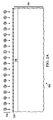
前記基板に配置されるn型埋め込み層であって、
アンチモンとヒ素とそれらの組み合わせとから成るグループから選択されるドーパントでの第1のドーピング濃度を有し、前記基板の頂部表面より下に埋め込み頂部表面を有する、メイン層と、
前記メイン層の下に位置し、前記第1のドーピング濃度よりも低い第2のドーピング濃度を有する、軽くドープされた層と、
を含む、前記n型埋め込み層と、
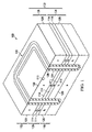
前記基板を介して貫通することなく前記基板の下部層に達するように前記n型埋め込み層を介して延在するディープトレンチ構造であって、前記ディープトレンチ構造の底部部分を覆って前記基板に接する誘電体ライナーを含む、前記ディープトレンチ構造と、
前記基板の前記頂部表面から延在して前記ディープトレンチ構造と前記n型埋め込み層の前記埋め込み頂部表面とに隣接する、n型の自己整合されたシンカーと、
を含む、半導体デバイス。 - 請求項1に記載の半導体デバイスであって、
前記p型半導体材料が、5Ωcm〜10Ωcmの抵抗率を有する、半導体デバイス。 - 請求項1に記載の半導体デバイスであって、
前記メイン層におけるn型ドーパントの少なくとも50パーセントがアンチモンである、半導体デバイス。 - 請求項1に記載の半導体デバイスであって、
前記ディープトレンチ構造が、前記基板の前記頂部表面に定義される閉ループ構成を含む、半導体デバイス。 - 請求項1に記載の半導体デバイスであって、
前記n型の自己整合されたシンカーが、前記n型埋め込み層の前記埋め込み頂部表面まで延在し、閉ループ構成を有する、半導体デバイス。 - 請求項1に記載の半導体デバイスであって、
前記第1のドーピング濃度が5×1018cm−3よりも大きく、前記第2のドーピング濃度が1×1016cm−3から10×1017cm−3までの範囲である、半導体デバイス。 - 請求項1に記載の半導体デバイスであって、
前記第1のドーピング濃度が前記第2のドーピング濃度よりも少なくとも50倍大きい、半導体デバイス。 - 請求項1に記載の半導体デバイスであって、
前記n型埋め込み層に結合される電極であって、前記n型埋め込み層を80ボルトと110ボルトの間にバイアスするように構成される、前記電極を更に含む、半導体デバイス。 - 半導体デバイスであって、
第1の導電型の第1のドーパントを含む第1の半導体層と、
前記第1の半導体層の上に位置する第2の半導体層であって、前記第1の導電型の第2のドーパントを含み、前記第1の半導体層から離れて面する頂部表面を有する、前記第2の半導体層と、
前記第1の半導体層と前記第2の半導体層との間に位置する埋め込み層であって、
前記第1の半導体層内の第1の埋め込み層であって、前記第1の半導体層に隣接し、前記第1の導電型と反対の第2の導電型の第3のドーパントを含み、第1のドーピング濃度を有する、前記第1の埋め込み層と、
前記第1の埋め込み層上に位置する第2の埋め込み層であって、前記第2の半導体層に隣接し、前記第1のドーピング濃度よりも高い第2のドーピング濃度で前記第2の導電型の第4のドーパントを含む、前記第2の埋め込み層と、
を有する、前記埋め込み層と、
を含む、半導体デバイス。 - 請求項9に記載の半導体デバイスであって、
前記第2の埋め込み層が、前記第1の半導体層内と前記第2の半導体層内とに延在する、半導体デバイス。 - 請求項9に記載の半導体デバイスであって、
前記第2の埋め込み層が、前記第2の半導体層内に位置する頂部層と、前記第1の半導体層内に位置して前記頂部層に隣接する底部層とを含む、半導体デバイス。 - 請求項9に記載の半導体デバイスであって、
前記第1の半導体層を介して貫通することなしに前記第1の半導体層に達するように前記第2の半導体層の前記頂部表面から前記埋め込み層を介して延在するディープトレンチ構造であって、前記ディープトレンチ構造の底部部分を覆って前記第1の半導体層に接する誘電体ライナーを含む、前記ディープトレンチ構造を更に含む、半導体デバイス。 - 請求項9に記載の半導体デバイスであって、
前記第2の半導体層から前記埋め込み層に延在し、閉ループ構造を有するシンカーを更に含む、半導体デバイス。 - 半導体デバイスを形成する方法であって、
p型半導体材料を含む基板の第1のエピタキシャル層を提供することと、
第1の注入層を形成するために、第1のn型ドーパントを第1のドーズ量で前記基板に注入することと、
第2の注入層を形成するために、第2のn型ドーパントを前記第1のドーズ量よりも少ない第2のドーズ量で100keVを上回るエネルギーで前記基板に注入することと、
前記基板にp型エピタキシャル層を定義し、前記p型エピタキシャル層の上に位置するn型埋め込み層を形成するために、少なくとも30分間の1150℃〜1225℃の温度での第1の熱駆動プロセスにおいて、前記基板を加熱することと、
を含み、
前記n型埋め込み層が、
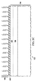
第1のドーピング濃度と前記基板の頂部表面より下の埋め込み頂部表面とを有するメイン層と、
前記p型エピタキシャル層より上で前記メイン層より下に位置し、前記第1のドーピング濃度よりも低い第2のドーピング濃度を有する、軽くドープされた層と、
を含む、方法。 - 請求項14に記載の方法であって、
前記p型エピタキシャル層における前記p型半導体材料が、5Ωcm〜10Ωcmの抵抗率を有する、方法。 - 請求項14に記載の方法であって、
前記第1のn型ドーパントが、アンチモンを含み、5×1014cm−2より大きい前記第1のドーズ量で注入される、方法。 - 請求項14に記載の方法であって、
前記第2のn型ドーパントが、リンを含み、前記基板にわたって注入される、方法。 - 請求項14に記載の方法であって、
前記n型埋め込み層が局地化されたn型埋め込み層を含むように、前記第2のn型ドーパントが、リンを含み、注入マスクにより露出されたエリアを介して前記基板に注入される、方法。 - 請求項14に記載の方法であって、
前記p型エピタキシャル層が形成された後に、少なくとも120分間の1125℃〜1200℃の温度での第2の熱駆動プロセスにおいて、前記基板を加熱することを更に含む、方法。 - 請求項14に記載の方法であって、
前記基板を介して貫通することなしに前記p型エピタキシャル層に達するように、前記n型埋め込み層を介して前記基板の前記頂部表面から延在する、前記基板におけるディープトレンチを形成することと、
前記ディープトレンチの底部部分を覆い、前記基板に接する誘電体ライナーを形成することと、
を更に含む、方法。 - 請求項20に記載の方法であって、
前記ディープトレンチが、前記基板の前記頂部表面に定義される閉ループ構成を含む、方法。 - 請求項20に記載の方法であって、
前記n型埋め込み層の前記埋め込み頂部表面に隣接する、前記基板におけるn型の自己整合されたシンカーを形成するように、前記ディープトレンチが形成された後に、前記ディープトレンチに近接する前記基板に第3のn型ドーパントを注入することを更に含む、方法。 - 請求項14に記載の方法であって、
前記n型埋め込み層の前記埋め込み頂部表面まで延在し、閉ループ構成を有する、前記基板におけるn型シンカーを形成することを更に含む、方法。
Applications Claiming Priority (5)
| Application Number | Priority Date | Filing Date | Title |
|---|---|---|---|
| US201461984205P | 2014-04-25 | 2014-04-25 | |
| US61/984,205 | 2014-04-25 | ||
| US14/555,330 US9385187B2 (en) | 2014-04-25 | 2014-11-26 | High breakdown N-type buried layer |
| US14/555,330 | 2014-11-26 | ||
| PCT/US2015/027699 WO2015164853A1 (en) | 2014-04-25 | 2015-04-27 | High breakdown n-type buried layer |
Publications (3)
| Publication Number | Publication Date |
|---|---|
| JP2017514319A JP2017514319A (ja) | 2017-06-01 |
| JP2017514319A5 JP2017514319A5 (ja) | 2018-06-07 |
| JP6657183B2 true JP6657183B2 (ja) | 2020-03-04 |
Family
ID=54333345
Family Applications (1)
| Application Number | Title | Priority Date | Filing Date |
|---|---|---|---|
| JP2017507937A Active JP6657183B2 (ja) | 2014-04-25 | 2015-04-27 | 高ブレークダウンn型埋め込み層 |
Country Status (4)
| Country | Link |
|---|---|
| US (2) | US9385187B2 (ja) |
| JP (1) | JP6657183B2 (ja) |
| CN (1) | CN106233439B (ja) |
| WO (1) | WO2015164853A1 (ja) |
Families Citing this family (4)
| Publication number | Priority date | Publication date | Assignee | Title |
|---|---|---|---|---|
| US9385187B2 (en) * | 2014-04-25 | 2016-07-05 | Texas Instruments Incorporated | High breakdown N-type buried layer |
| DE102017103782B4 (de) * | 2017-02-23 | 2021-03-25 | Infineon Technologies Ag | Halbleitervorrichtung mit einer vergrabenen Schicht und Herstellungsverfahren hierfür |
| CN114695505A (zh) * | 2020-12-29 | 2022-07-01 | 无锡华润上华科技有限公司 | 电子设备、半导体器件及其制备方法 |
| CN118041270A (zh) * | 2022-11-04 | 2024-05-14 | 广州乐仪投资有限公司 | 半导体结构的制备方法、半导体结构及电子设备 |
Family Cites Families (36)
| Publication number | Priority date | Publication date | Assignee | Title |
|---|---|---|---|---|
| US4666556A (en) | 1986-05-12 | 1987-05-19 | International Business Machines Corporation | Trench sidewall isolation by polysilicon oxidation |
| US4980747A (en) | 1986-12-22 | 1990-12-25 | Texas Instruments Inc. | Deep trench isolation with surface contact to substrate |
| US5192708A (en) * | 1991-04-29 | 1993-03-09 | International Business Machines Corporation | Sub-layer contact technique using in situ doped amorphous silicon and solid phase recrystallization |
| US5994755A (en) * | 1991-10-30 | 1999-11-30 | Intersil Corporation | Analog-to-digital converter and method of fabrication |
| JPH0799771B2 (ja) | 1992-06-26 | 1995-10-25 | インターナショナル・ビジネス・マシーンズ・コーポレイション | 皮膜中の応力を制御する方法 |
| JP3285435B2 (ja) * | 1993-07-07 | 2002-05-27 | 三菱電機株式会社 | 半導体装置およびその製造方法 |
| JPH08236614A (ja) * | 1995-02-27 | 1996-09-13 | Nippondenso Co Ltd | 半導体装置の製造方法 |
| US6218722B1 (en) | 1997-02-14 | 2001-04-17 | Gennum Corporation | Antifuse based on silicided polysilicon bipolar transistor |
| US20010013610A1 (en) * | 1999-08-02 | 2001-08-16 | Min-Hwa Chi | Vertical bipolar transistor based on gate induced drain leakage current |
| US6661042B2 (en) * | 2002-03-11 | 2003-12-09 | Monolithic System Technology, Inc. | One-transistor floating-body DRAM cell in bulk CMOS process with electrically isolated charge storage region |
| US6943426B2 (en) | 2002-08-14 | 2005-09-13 | Advanced Analogic Technologies, Inc. | Complementary analog bipolar transistors with trench-constrained isolation diffusion |
| US7041572B2 (en) | 2002-10-25 | 2006-05-09 | Vanguard International Semiconductor Corporation | Fabrication method for a deep trench isolation structure of a high-voltage device |
| US7635621B2 (en) * | 2002-11-22 | 2009-12-22 | Micrel, Inc. | Lateral double-diffused metal oxide semiconductor (LDMOS) device with an enhanced drift region that has an improved Ron area product |
| SE526366C3 (sv) * | 2003-03-21 | 2005-10-26 | Silex Microsystems Ab | Elektriska anslutningar i substrat |
| US6815780B1 (en) | 2003-04-15 | 2004-11-09 | Motorola, Inc. | Semiconductor component with substrate injection protection structure |
| JP4292964B2 (ja) * | 2003-08-08 | 2009-07-08 | 三菱電機株式会社 | 縦型半導体装置 |
| US7639713B2 (en) | 2004-01-21 | 2009-12-29 | Emc Corporation | Database block network attached storage packet joining |
| JP4592340B2 (ja) | 2004-06-29 | 2010-12-01 | 三洋電機株式会社 | 半導体装置の製造方法 |
| TW200739693A (en) * | 2005-03-24 | 2007-10-16 | Nxp Bv | Method of manufacturing a semiconductor device having a buried doped region |
| US7723204B2 (en) | 2006-03-27 | 2010-05-25 | Freescale Semiconductor, Inc. | Semiconductor device with a multi-plate isolation structure |
| US7410862B2 (en) | 2006-04-28 | 2008-08-12 | International Business Machines Corporation | Trench capacitor and method for fabricating the same |
| WO2008086348A2 (en) * | 2007-01-09 | 2008-07-17 | Maxpower Semiconductor, Inc. | Semiconductor device and method of manufacturing the same |
| US8614151B2 (en) | 2008-01-04 | 2013-12-24 | Micron Technology, Inc. | Method of etching a high aspect ratio contact |
| US7989875B2 (en) * | 2008-11-24 | 2011-08-02 | Nxp B.V. | BiCMOS integration of multiple-times-programmable non-volatile memories |
| KR101610826B1 (ko) | 2009-03-18 | 2016-04-11 | 삼성전자주식회사 | 커패시터를 갖는 반도체 장치의 형성방법 |
| US8476530B2 (en) | 2009-06-22 | 2013-07-02 | International Business Machines Corporation | Self-aligned nano-scale device with parallel plate electrodes |
| US20110062554A1 (en) | 2009-09-17 | 2011-03-17 | Hsing Michael R | High voltage floating well in a silicon die |
| US8334190B2 (en) | 2010-05-07 | 2012-12-18 | Texas Instruments Incorporated | Single step CMP for polishing three or more layer film stacks |
| US8399924B2 (en) | 2010-06-17 | 2013-03-19 | Texas Instruments Incorporated | High voltage transistor using diluted drain |
| US8785971B2 (en) * | 2011-11-23 | 2014-07-22 | Amazing Microelectronic Corp. | Transient voltage suppressor without leakage current |
| US8642423B2 (en) * | 2011-11-30 | 2014-02-04 | International Business Machines Corporation | Polysilicon/metal contact resistance in deep trench |
| US9356133B2 (en) * | 2012-02-01 | 2016-05-31 | Texas Instruments Incorporated | Medium voltage MOSFET device |
| US9293357B2 (en) | 2012-07-02 | 2016-03-22 | Texas Instruments Incorporated | Sinker with a reduced width |
| US9082719B2 (en) | 2012-10-19 | 2015-07-14 | Infineon Technologies Ag | Method for removing a dielectric layer from a bottom of a trench |
| US9136368B2 (en) * | 2013-10-03 | 2015-09-15 | Texas Instruments Incorporated | Trench gate trench field plate semi-vertical semi-lateral MOSFET |
| US9385187B2 (en) * | 2014-04-25 | 2016-07-05 | Texas Instruments Incorporated | High breakdown N-type buried layer |
-
2014
- 2014-11-26 US US14/555,330 patent/US9385187B2/en active Active
-
2015
- 2015-04-27 CN CN201580020171.3A patent/CN106233439B/zh active Active
- 2015-04-27 WO PCT/US2015/027699 patent/WO2015164853A1/en active Application Filing
- 2015-04-27 JP JP2017507937A patent/JP6657183B2/ja active Active
-
2016
- 2016-06-07 US US15/175,192 patent/US9673273B2/en active Active
Also Published As
| Publication number | Publication date |
|---|---|
| CN106233439A (zh) | 2016-12-14 |
| US9385187B2 (en) | 2016-07-05 |
| US9673273B2 (en) | 2017-06-06 |
| US20160315141A1 (en) | 2016-10-27 |
| JP2017514319A (ja) | 2017-06-01 |
| US20150311281A1 (en) | 2015-10-29 |
| WO2015164853A1 (en) | 2015-10-29 |
| CN106233439B (zh) | 2021-01-01 |
Similar Documents
| Publication | Publication Date | Title |
|---|---|---|
| JP7279277B2 (ja) | 複数遮蔽トレンチゲートfet | |
| JP7189403B2 (ja) | ディープトレンチ充填のためのポリサンドイッチ | |
| JP5350815B2 (ja) | 半導体装置 | |
| US7915155B2 (en) | Double trench for isolation of semiconductor devices | |
| US8222114B2 (en) | Manufacturing approach for collector and a buried layer of bipolar transistor | |
| US6534836B1 (en) | MOSFET semiconductor device | |
| JP6492068B2 (ja) | インテグレートされたパワー技術における垂直トレンチmosfetデバイス | |
| JP5287621B2 (ja) | 半導体装置 | |
| KR20120047032A (ko) | 반도체 소자 및 이의 제조 방법 | |
| US9099321B2 (en) | Method for fabricating power semiconductor device | |
| JP6657183B2 (ja) | 高ブレークダウンn型埋め込み層 | |
| US8753937B2 (en) | Manufacturing method of power transistor device with super junction | |
| CN105633042B (zh) | 超高纵横比接触件 | |
| US9431286B1 (en) | Deep trench with self-aligned sinker | |
| JP2012049466A5 (ja) | ||
| KR100902585B1 (ko) | 트렌치 게이트형 모스트랜지스터 및 그 제조방법 | |
| JP5743246B2 (ja) | 半導体装置及び関連する製造方法 | |
| JP2004311673A (ja) | 半導体装置の製造方法 | |
| CN103219240B (zh) | 一种半导体器件的制造方法 | |
| JP2010161250A (ja) | 半導体装置の製造方法及び半導体装置 | |
| CN108461514A (zh) | Cmos图形传感器的隔离结构及其形成方法 |
Legal Events
| Date | Code | Title | Description |
|---|---|---|---|
| A521 | Request for written amendment filed |
Free format text: JAPANESE INTERMEDIATE CODE: A821 Effective date: 20161025 |
|
| A521 | Request for written amendment filed |
Free format text: JAPANESE INTERMEDIATE CODE: A523 Effective date: 20180418 |
|
| A621 | Written request for application examination |
Free format text: JAPANESE INTERMEDIATE CODE: A621 Effective date: 20180418 |
|
| A131 | Notification of reasons for refusal |
Free format text: JAPANESE INTERMEDIATE CODE: A131 Effective date: 20190508 |
|
| A521 | Request for written amendment filed |
Free format text: JAPANESE INTERMEDIATE CODE: A523 Effective date: 20190808 |
|
| A601 | Written request for extension of time |
Free format text: JAPANESE INTERMEDIATE CODE: A601 Effective date: 20190808 |
|
| A131 | Notification of reasons for refusal |
Free format text: JAPANESE INTERMEDIATE CODE: A131 Effective date: 20190918 |
|
| A601 | Written request for extension of time |
Free format text: JAPANESE INTERMEDIATE CODE: A601 Effective date: 20191218 |
|
| A521 | Request for written amendment filed |
Free format text: JAPANESE INTERMEDIATE CODE: A523 Effective date: 20191220 |
|
| A131 | Notification of reasons for refusal |
Free format text: JAPANESE INTERMEDIATE CODE: A131 Effective date: 20200108 |
|
| A521 | Request for written amendment filed |
Free format text: JAPANESE INTERMEDIATE CODE: A523 Effective date: 20200108 |
|
| TRDD | Decision of grant or rejection written | ||
| A01 | Written decision to grant a patent or to grant a registration (utility model) |
Free format text: JAPANESE INTERMEDIATE CODE: A01 Effective date: 20200122 |
|
| A61 | First payment of annual fees (during grant procedure) |
Free format text: JAPANESE INTERMEDIATE CODE: A61 Effective date: 20200205 |
|
| R150 | Certificate of patent or registration of utility model |
Ref document number: 6657183 Country of ref document: JP Free format text: JAPANESE INTERMEDIATE CODE: R150 |
|
| S111 | Request for change of ownership or part of ownership |
Free format text: JAPANESE INTERMEDIATE CODE: R313117 |
|
| S111 | Request for change of ownership or part of ownership |
Free format text: JAPANESE INTERMEDIATE CODE: R313117 |
|
| S111 | Request for change of ownership or part of ownership |
Free format text: JAPANESE INTERMEDIATE CODE: R313117 |
|
| R350 | Written notification of registration of transfer |
Free format text: JAPANESE INTERMEDIATE CODE: R350 |
|
| R250 | Receipt of annual fees |
Free format text: JAPANESE INTERMEDIATE CODE: R250 |
|
| R250 | Receipt of annual fees |
Free format text: JAPANESE INTERMEDIATE CODE: R250 |