JP6361237B2 - ブロワユニット - Google Patents
ブロワユニット Download PDFInfo
- Publication number
- JP6361237B2 JP6361237B2 JP2014075388A JP2014075388A JP6361237B2 JP 6361237 B2 JP6361237 B2 JP 6361237B2 JP 2014075388 A JP2014075388 A JP 2014075388A JP 2014075388 A JP2014075388 A JP 2014075388A JP 6361237 B2 JP6361237 B2 JP 6361237B2
- Authority
- JP
- Japan
- Prior art keywords
- door
- air
- fan
- opening
- mode
- Prior art date
- Legal status (The legal status is an assumption and is not a legal conclusion. Google has not performed a legal analysis and makes no representation as to the accuracy of the status listed.)
- Expired - Fee Related
Links
- 238000007664 blowing Methods 0.000 description 46
- 238000001816 cooling Methods 0.000 description 19
- 230000007246 mechanism Effects 0.000 description 15
- 230000005540 biological transmission Effects 0.000 description 13
- 239000011347 resin Substances 0.000 description 7
- 229920005989 resin Polymers 0.000 description 7
- 238000004378 air conditioning Methods 0.000 description 6
- 238000005192 partition Methods 0.000 description 6
- 230000000694 effects Effects 0.000 description 4
- 239000004743 Polypropylene Substances 0.000 description 3
- -1 polypropylene Polymers 0.000 description 3
- 229920001155 polypropylene Polymers 0.000 description 3
- 230000015572 biosynthetic process Effects 0.000 description 1
- 239000000498 cooling water Substances 0.000 description 1
- 230000007423 decrease Effects 0.000 description 1
- 238000010586 diagram Methods 0.000 description 1
- 238000009434 installation Methods 0.000 description 1
- 239000003507 refrigerant Substances 0.000 description 1
- 238000005057 refrigeration Methods 0.000 description 1
- 230000008016 vaporization Effects 0.000 description 1
- 238000009834 vaporization Methods 0.000 description 1
- XLYOFNOQVPJJNP-UHFFFAOYSA-N water Substances O XLYOFNOQVPJJNP-UHFFFAOYSA-N 0.000 description 1
Images


Classifications
-
- F—MECHANICAL ENGINEERING; LIGHTING; HEATING; WEAPONS; BLASTING
- F04—POSITIVE - DISPLACEMENT MACHINES FOR LIQUIDS; PUMPS FOR LIQUIDS OR ELASTIC FLUIDS
- F04D—NON-POSITIVE-DISPLACEMENT PUMPS
- F04D29/00—Details, component parts, or accessories
- F04D29/40—Casings; Connections of working fluid
- F04D29/42—Casings; Connections of working fluid for radial or helico-centrifugal pumps
- F04D29/4206—Casings; Connections of working fluid for radial or helico-centrifugal pumps especially adapted for elastic fluid pumps
- F04D29/4226—Fan casings
- F04D29/4246—Fan casings comprising more than one outlet
-
- B—PERFORMING OPERATIONS; TRANSPORTING
- B60—VEHICLES IN GENERAL
- B60H—ARRANGEMENTS OF HEATING, COOLING, VENTILATING OR OTHER AIR-TREATING DEVICES SPECIALLY ADAPTED FOR PASSENGER OR GOODS SPACES OF VEHICLES
- B60H1/00—Heating, cooling or ventilating [HVAC] devices
- B60H1/00007—Combined heating, ventilating, or cooling devices
- B60H1/00021—Air flow details of HVAC devices
- B60H1/00035—Air flow details of HVAC devices for sending an air stream of uniform temperature into the passenger compartment
- B60H1/0005—Air flow details of HVAC devices for sending an air stream of uniform temperature into the passenger compartment the air being firstly cooled and subsequently heated or vice versa
-
- F—MECHANICAL ENGINEERING; LIGHTING; HEATING; WEAPONS; BLASTING
- F04—POSITIVE - DISPLACEMENT MACHINES FOR LIQUIDS; PUMPS FOR LIQUIDS OR ELASTIC FLUIDS
- F04D—NON-POSITIVE-DISPLACEMENT PUMPS
- F04D17/00—Radial-flow pumps, e.g. centrifugal pumps; Helico-centrifugal pumps
- F04D17/08—Centrifugal pumps
- F04D17/16—Centrifugal pumps for displacing without appreciable compression
- F04D17/162—Double suction pumps
-
- F—MECHANICAL ENGINEERING; LIGHTING; HEATING; WEAPONS; BLASTING
- F04—POSITIVE - DISPLACEMENT MACHINES FOR LIQUIDS; PUMPS FOR LIQUIDS OR ELASTIC FLUIDS
- F04D—NON-POSITIVE-DISPLACEMENT PUMPS
- F04D29/00—Details, component parts, or accessories
- F04D29/26—Rotors specially for elastic fluids
- F04D29/28—Rotors specially for elastic fluids for centrifugal or helico-centrifugal pumps for radial-flow or helico-centrifugal pumps
- F04D29/281—Rotors specially for elastic fluids for centrifugal or helico-centrifugal pumps for radial-flow or helico-centrifugal pumps for fans or blowers
- F04D29/282—Rotors specially for elastic fluids for centrifugal or helico-centrifugal pumps for radial-flow or helico-centrifugal pumps for fans or blowers the leading edge of each vane being substantially parallel to the rotation axis
-
- F—MECHANICAL ENGINEERING; LIGHTING; HEATING; WEAPONS; BLASTING
- F04—POSITIVE - DISPLACEMENT MACHINES FOR LIQUIDS; PUMPS FOR LIQUIDS OR ELASTIC FLUIDS
- F04D—NON-POSITIVE-DISPLACEMENT PUMPS
- F04D29/00—Details, component parts, or accessories
- F04D29/40—Casings; Connections of working fluid
- F04D29/42—Casings; Connections of working fluid for radial or helico-centrifugal pumps
- F04D29/44—Fluid-guiding means, e.g. diffusers
- F04D29/46—Fluid-guiding means, e.g. diffusers adjustable
- F04D29/462—Fluid-guiding means, e.g. diffusers adjustable especially adapted for elastic fluid pumps
- F04D29/464—Fluid-guiding means, e.g. diffusers adjustable especially adapted for elastic fluid pumps adjusting flow cross-section, otherwise than by using adjustable stator blades
-
- B—PERFORMING OPERATIONS; TRANSPORTING
- B60—VEHICLES IN GENERAL
- B60H—ARRANGEMENTS OF HEATING, COOLING, VENTILATING OR OTHER AIR-TREATING DEVICES SPECIALLY ADAPTED FOR PASSENGER OR GOODS SPACES OF VEHICLES
- B60H1/00—Heating, cooling or ventilating [HVAC] devices
- B60H1/00007—Combined heating, ventilating, or cooling devices
- B60H1/00021—Air flow details of HVAC devices
- B60H2001/00078—Assembling, manufacturing or layout details
- B60H2001/00099—Assembling, manufacturing or layout details comprising additional ventilating means
Landscapes
- Engineering & Computer Science (AREA)
- Mechanical Engineering (AREA)
- General Engineering & Computer Science (AREA)
- Physics & Mathematics (AREA)
- Thermal Sciences (AREA)
- Air-Conditioning For Vehicles (AREA)
- Structures Of Non-Positive Displacement Pumps (AREA)
Description
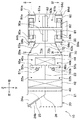
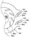
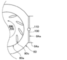
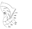
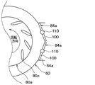
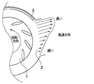
図1は、本発明の一実施形態における車両用空調装置の空調ユニットの断面図である。図1において上、下、左、右の各矢印は、当該車両用空調装置を車両に搭載した際の方向を示している。
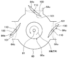
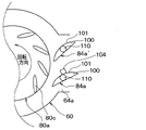
上記第1実施形態では、1つの吹出開口部に1つのバタフライドアを設けた例について説明したが、これに代えて、本第2実施形態では、1つの吹出開口部に対して複数のモードドアを設ける例を示す。
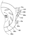
上記第1、第2の実施形態では、モードドア84a〜84eとして、ドア本体に円弧部101を備えるバタフライドアを設けた例について、これに代えて、本第3の実施形態では、モードドア84a〜84eとして、図8、図9のバタフライドアを用いる例について説明する。
上記第3実施形態では、1つの吹出開口部に1つのバタフライドアを設けた例について説明したが、これに代えて、本第4実施形態では、1つの吹出開口部に複数のモードドアを設ける例を示す。
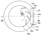
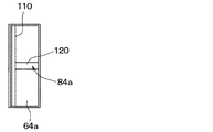
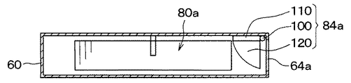
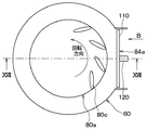
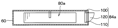
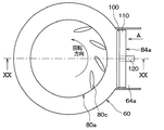
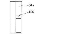
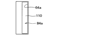
上記第1〜4の実施形態では、ファンから吹出開口部に吹き出される空気流を回転方向に分けるために、モードドア84a〜84eとしてバタフライドアを用いた例について説明したが、これに代えて、本第5実施形態では、モードドア84a〜84eとして、ガイド付の片持ちドアを用いる例について図12〜図17を参照して説明する。
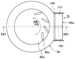
上記第5実施形態では、ドア本体100にガイド120を備えた片持ちドアをモードドア84a〜84eとした例について説明したが、これに代えて、本第6実施形態では、ドア本体100にガイド120を備えたロータリドアをモードドア84a〜84eとする。
本第7実施形態では、上記第1実施形態において、ファンから吹き出される空気流を調整するために、ドア本体にリブを設けたバタフライドアをモードドアとする例について説明する。
上記第7実施形態では、上記第1実施形態のドア本体100にリブ104を設けたバタフライドアをモードドア84aとする例について説明したが、これに代えて、モードドア84a以外のモードドア84b〜84eをドア本体100にリブ(突起部)104を設けたバタフライドアとしてもよい。同様に、上記第2〜7実施形態のドア本体100にリブ104を設けたドアをモードドア84a〜84eとしてもよい。
20 ヒータユニット
30 ブロワユニット
60 ブロワケース
64a、64b フェイス吹出開口部
64c デフロスタ吹出開口部
64d、64e フット吹出開口部
81 回転軸(第1回転軸)
80a、80b ファン
60 ブロワケース
84a〜84e モードドア
Claims (6)
- 第1回転軸(81)と、
前記第1回転軸に支持されて、前記第1回転軸の回転に伴って前記第1回転軸の径方向外側に空気を吹き出すファン(80a、80b)と、
前記ファンを収納して前記ファンに対して前記径方向外側に開口する吹出開口部(64a〜64e)を有するケース(60)と、
前記吹出開口部を開閉するドア(84a〜84e)と、を備え、
前記ドアは、前記吹出開口部を開けた状態で、前記ファンから前記吹出開口部に吹き出される空気流を前記第1回転軸の回転方向に分けるように構成されており、
前記ドアは、前記吹出開口部を開けた状態で、前記ファンから前記吹出開口部に吹き出される空気流を前記第1回転軸の回転方向に分けるためのガイド(120)を備えることを特徴とするブロワユニット。 - 前記ドアは、前記ファンから前記吹出開口部に吹き出される空気流を調整するための突起部(102)を備えることを特徴とする請求項1に記載のブロワユニット。
- 第1回転軸(81)と、
前記第1回転軸に支持されて、前記第1回転軸の回転に伴って前記第1回転軸の径方向外側に空気を吹き出すファン(80a、80b)と、
前記ファンを収納して前記ファンに対して前記径方向外側に開口する吹出開口部(64a〜64e)を有するケース(60)と、
前記吹出開口部を開閉するドア(84a〜84e)と、を備え、
前記ドアは、前記吹出開口部を開けた状態で、前記ファンから前記吹出開口部に吹き出される空気流を前記第1回転軸の回転方向に分けるように構成されており、
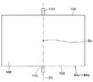
前記ドアは、前記ファンから前記吹出開口部に吹き出される空気流を調整するための突起部(102)を備えることを特徴とするブロワユニット。 - 前記ドアは、板状に形成されているドア本体(100)と、前記ドア本体の中央部(Sa)を軸線(D1)が通過し、かつ前記ドア本体の側面(102、103)から突出するように形成されている第2回転軸(110)とを備え、前記第2回転軸の軸線を中心として回転自在に支持されているバタフライドアであり、
さらに前記バタフライドアが前記吹出開口部を開けた状態で、前記ファンから前記吹出開口部に吹き出される空気流を前記バタフライドアが前記第1回転軸の回転方向に分けるようになっていることを特徴とする請求項3に記載のブロワユニット。 - 1つの前記吹出開口部に対して複数の前記バタフライドアが配置されていることを特徴とする請求項4に記載のブロワユニット。
- 前記ドア本体は、前記第2回転軸の軸線方向から視て厚み方向に凸となる円弧状に形成されている円弧部(101)を備えることを特徴とする請求項4または5に記載のブロワユニット。
Priority Applications (2)
| Application Number | Priority Date | Filing Date | Title |
|---|---|---|---|
| JP2014075388A JP6361237B2 (ja) | 2014-04-01 | 2014-04-01 | ブロワユニット |
| PCT/JP2015/001738 WO2015151476A1 (ja) | 2014-04-01 | 2015-03-26 | ブロワユニット |
Applications Claiming Priority (1)
| Application Number | Priority Date | Filing Date | Title |
|---|---|---|---|
| JP2014075388A JP6361237B2 (ja) | 2014-04-01 | 2014-04-01 | ブロワユニット |
Publications (2)
| Publication Number | Publication Date |
|---|---|
| JP2015197065A JP2015197065A (ja) | 2015-11-09 |
| JP6361237B2 true JP6361237B2 (ja) | 2018-07-25 |
Family
ID=54239822
Family Applications (1)
| Application Number | Title | Priority Date | Filing Date |
|---|---|---|---|
| JP2014075388A Expired - Fee Related JP6361237B2 (ja) | 2014-04-01 | 2014-04-01 | ブロワユニット |
Country Status (2)
| Country | Link |
|---|---|
| JP (1) | JP6361237B2 (ja) |
| WO (1) | WO2015151476A1 (ja) |
Families Citing this family (2)
| Publication number | Priority date | Publication date | Assignee | Title |
|---|---|---|---|---|
| CN110657128B (zh) * | 2019-10-17 | 2024-12-06 | 苏州安泰空气技术有限公司 | 一种无蜗壳风机的矢量调节组件 |
| KR102518293B1 (ko) * | 2021-09-03 | 2023-04-04 | 엘지전자 주식회사 | 블로어 |
Family Cites Families (7)
| Publication number | Priority date | Publication date | Assignee | Title |
|---|---|---|---|---|
| JPS5428751Y2 (ja) * | 1975-08-30 | 1979-09-14 | ||
| JPS54153453A (en) * | 1978-05-25 | 1979-12-03 | Nissan Motor Co Ltd | Air conditioner for vehicle |
| JPS5994000A (ja) * | 1982-11-22 | 1984-05-30 | Hitachi Ltd | 遠心形送風機 |
| JP3296186B2 (ja) * | 1995-05-10 | 2002-06-24 | 株式会社デンソー | 車両用空調装置 |
| JP3928261B2 (ja) * | 1997-09-03 | 2007-06-13 | 株式会社デンソー | 車両用空調装置 |
| JP2003214398A (ja) * | 2002-01-23 | 2003-07-30 | Sharp Corp | 送風装置及びこれを備えた加熱調理器 |
| JP5056057B2 (ja) * | 2007-02-20 | 2012-10-24 | 株式会社デンソー | 車両用空調装置 |
-
2014
- 2014-04-01 JP JP2014075388A patent/JP6361237B2/ja not_active Expired - Fee Related
-
2015
- 2015-03-26 WO PCT/JP2015/001738 patent/WO2015151476A1/ja not_active Ceased
Also Published As
| Publication number | Publication date |
|---|---|
| JP2015197065A (ja) | 2015-11-09 |
| WO2015151476A1 (ja) | 2015-10-08 |
Similar Documents
| Publication | Publication Date | Title |
|---|---|---|
| JP5625993B2 (ja) | 車両用空調装置 | |
| WO2015059885A1 (ja) | 車両用空調ユニット | |
| JP6341114B2 (ja) | 車両用空調装置 | |
| WO2018096871A1 (ja) | 車両用空調装置 | |
| WO2012108146A1 (ja) | 空調用複合機能ドア及び車両用空調装置 | |
| JP6256943B2 (ja) | 車両用空調装置 | |
| WO2014156061A1 (ja) | 車両用空調装置 | |
| JP6361237B2 (ja) | ブロワユニット | |
| WO2014058009A1 (ja) | 車両用空調装置 | |
| JP2009292197A (ja) | 車両用空調装置 | |
| JP6269432B2 (ja) | 車両用空調装置 | |
| JP6672124B2 (ja) | 車両用の空調装置 | |
| JP2006168584A (ja) | 空気通路切替装置および車両用空調装置 | |
| JP6234747B2 (ja) | 車両用空調装置 | |
| JP6213350B2 (ja) | 車両用空調装置 | |
| JP2009006896A (ja) | 車両用空調装置 | |
| JP6237328B2 (ja) | 車両用空調装置 | |
| JP5353823B2 (ja) | 空調装置 | |
| WO2020255951A1 (ja) | 空調ユニット | |
| JP4434072B2 (ja) | リンク装置および車両用空調装置 | |
| JP6592964B2 (ja) | 車両用空調ユニット | |
| JP2015196451A (ja) | 空調装置 | |
| JP2002274158A (ja) | 空調装置のリンクプレート構造 | |
| JP2009018780A (ja) | 車両用空調装置 | |
| JP5556757B2 (ja) | 車両用空調装置 |
Legal Events
| Date | Code | Title | Description |
|---|---|---|---|
| A621 | Written request for application examination |
Free format text: JAPANESE INTERMEDIATE CODE: A621 Effective date: 20170215 |
|
| A131 | Notification of reasons for refusal |
Free format text: JAPANESE INTERMEDIATE CODE: A131 Effective date: 20171205 |
|
| A521 | Request for written amendment filed |
Free format text: JAPANESE INTERMEDIATE CODE: A523 Effective date: 20180129 |
|
| TRDD | Decision of grant or rejection written | ||
| A01 | Written decision to grant a patent or to grant a registration (utility model) |
Free format text: JAPANESE INTERMEDIATE CODE: A01 Effective date: 20180529 |
|
| A61 | First payment of annual fees (during grant procedure) |
Free format text: JAPANESE INTERMEDIATE CODE: A61 Effective date: 20180611 |
|
| R151 | Written notification of patent or utility model registration |
Ref document number: 6361237 Country of ref document: JP Free format text: JAPANESE INTERMEDIATE CODE: R151 |
|
| R250 | Receipt of annual fees |
Free format text: JAPANESE INTERMEDIATE CODE: R250 |
|
| LAPS | Cancellation because of no payment of annual fees |