JP6017798B2 - 排気流路用弁装置 - Google Patents
排気流路用弁装置 Download PDFInfo
- Publication number
- JP6017798B2 JP6017798B2 JP2012037552A JP2012037552A JP6017798B2 JP 6017798 B2 JP6017798 B2 JP 6017798B2 JP 2012037552 A JP2012037552 A JP 2012037552A JP 2012037552 A JP2012037552 A JP 2012037552A JP 6017798 B2 JP6017798 B2 JP 6017798B2
- Authority
- JP
- Japan
- Prior art keywords
- rotation axis
- valve device
- valve
- link
- link member
- Prior art date
- Legal status (The legal status is an assumption and is not a legal conclusion. Google has not performed a legal analysis and makes no representation as to the accuracy of the status listed.)
- Active
Links
Images


Classifications
-
- F—MECHANICAL ENGINEERING; LIGHTING; HEATING; WEAPONS; BLASTING
- F01—MACHINES OR ENGINES IN GENERAL; ENGINE PLANTS IN GENERAL; STEAM ENGINES
- F01N—GAS-FLOW SILENCERS OR EXHAUST APPARATUS FOR MACHINES OR ENGINES IN GENERAL; GAS-FLOW SILENCERS OR EXHAUST APPARATUS FOR INTERNAL COMBUSTION ENGINES
- F01N1/00—Silencing apparatus characterised by method of silencing
- F01N1/16—Silencing apparatus characterised by method of silencing by using movable parts
- F01N1/168—Silencing apparatus characterised by method of silencing by using movable parts for controlling or modifying silencing characteristics only
-
- F—MECHANICAL ENGINEERING; LIGHTING; HEATING; WEAPONS; BLASTING
- F01—MACHINES OR ENGINES IN GENERAL; ENGINE PLANTS IN GENERAL; STEAM ENGINES
- F01N—GAS-FLOW SILENCERS OR EXHAUST APPARATUS FOR MACHINES OR ENGINES IN GENERAL; GAS-FLOW SILENCERS OR EXHAUST APPARATUS FOR INTERNAL COMBUSTION ENGINES
- F01N1/00—Silencing apparatus characterised by method of silencing
- F01N1/08—Silencing apparatus characterised by method of silencing by reducing exhaust energy by throttling or whirling
- F01N1/084—Silencing apparatus characterised by method of silencing by reducing exhaust energy by throttling or whirling the gases flowing through the silencer two or more times longitudinally in opposite directions, e.g. using parallel or concentric tubes
-
- F—MECHANICAL ENGINEERING; LIGHTING; HEATING; WEAPONS; BLASTING
- F01—MACHINES OR ENGINES IN GENERAL; ENGINE PLANTS IN GENERAL; STEAM ENGINES
- F01N—GAS-FLOW SILENCERS OR EXHAUST APPARATUS FOR MACHINES OR ENGINES IN GENERAL; GAS-FLOW SILENCERS OR EXHAUST APPARATUS FOR INTERNAL COMBUSTION ENGINES
- F01N1/00—Silencing apparatus characterised by method of silencing
- F01N1/08—Silencing apparatus characterised by method of silencing by reducing exhaust energy by throttling or whirling
- F01N1/086—Silencing apparatus characterised by method of silencing by reducing exhaust energy by throttling or whirling having means to impart whirling motion to the gases
- F01N1/088—Silencing apparatus characterised by method of silencing by reducing exhaust energy by throttling or whirling having means to impart whirling motion to the gases using vanes arranged on gas flow path or gas flow tubes with tangentially directed apertures
-
- F—MECHANICAL ENGINEERING; LIGHTING; HEATING; WEAPONS; BLASTING
- F01—MACHINES OR ENGINES IN GENERAL; ENGINE PLANTS IN GENERAL; STEAM ENGINES
- F01N—GAS-FLOW SILENCERS OR EXHAUST APPARATUS FOR MACHINES OR ENGINES IN GENERAL; GAS-FLOW SILENCERS OR EXHAUST APPARATUS FOR INTERNAL COMBUSTION ENGINES
- F01N1/00—Silencing apparatus characterised by method of silencing
- F01N1/16—Silencing apparatus characterised by method of silencing by using movable parts
- F01N1/165—Silencing apparatus characterised by method of silencing by using movable parts for adjusting flow area
-
- F—MECHANICAL ENGINEERING; LIGHTING; HEATING; WEAPONS; BLASTING
- F01—MACHINES OR ENGINES IN GENERAL; ENGINE PLANTS IN GENERAL; STEAM ENGINES
- F01N—GAS-FLOW SILENCERS OR EXHAUST APPARATUS FOR MACHINES OR ENGINES IN GENERAL; GAS-FLOW SILENCERS OR EXHAUST APPARATUS FOR INTERNAL COMBUSTION ENGINES
- F01N1/00—Silencing apparatus characterised by method of silencing
- F01N1/16—Silencing apparatus characterised by method of silencing by using movable parts
- F01N1/166—Silencing apparatus characterised by method of silencing by using movable parts for changing gas flow path through the silencer or for adjusting the dimensions of a chamber or a pipe
-
- F—MECHANICAL ENGINEERING; LIGHTING; HEATING; WEAPONS; BLASTING
- F01—MACHINES OR ENGINES IN GENERAL; ENGINE PLANTS IN GENERAL; STEAM ENGINES
- F01N—GAS-FLOW SILENCERS OR EXHAUST APPARATUS FOR MACHINES OR ENGINES IN GENERAL; GAS-FLOW SILENCERS OR EXHAUST APPARATUS FOR INTERNAL COMBUSTION ENGINES
- F01N1/00—Silencing apparatus characterised by method of silencing
- F01N1/16—Silencing apparatus characterised by method of silencing by using movable parts
- F01N1/18—Silencing apparatus characterised by method of silencing by using movable parts having rotary movement
-
- F—MECHANICAL ENGINEERING; LIGHTING; HEATING; WEAPONS; BLASTING
- F16—ENGINEERING ELEMENTS AND UNITS; GENERAL MEASURES FOR PRODUCING AND MAINTAINING EFFECTIVE FUNCTIONING OF MACHINES OR INSTALLATIONS; THERMAL INSULATION IN GENERAL
- F16K—VALVES; TAPS; COCKS; ACTUATING-FLOATS; DEVICES FOR VENTING OR AERATING
- F16K15/00—Check valves
- F16K15/02—Check valves with guided rigid valve members
- F16K15/03—Check valves with guided rigid valve members with a hinged closure member or with a pivoted closure member
- F16K15/033—Check valves with guided rigid valve members with a hinged closure member or with a pivoted closure member spring-loaded
-
- F—MECHANICAL ENGINEERING; LIGHTING; HEATING; WEAPONS; BLASTING
- F01—MACHINES OR ENGINES IN GENERAL; ENGINE PLANTS IN GENERAL; STEAM ENGINES
- F01N—GAS-FLOW SILENCERS OR EXHAUST APPARATUS FOR MACHINES OR ENGINES IN GENERAL; GAS-FLOW SILENCERS OR EXHAUST APPARATUS FOR INTERNAL COMBUSTION ENGINES
- F01N2240/00—Combination or association of two or more different exhaust treating devices, or of at least one such device with an auxiliary device, not covered by indexing codes F01N2230/00 or F01N2250/00, one of the devices being
- F01N2240/36—Combination or association of two or more different exhaust treating devices, or of at least one such device with an auxiliary device, not covered by indexing codes F01N2230/00 or F01N2250/00, one of the devices being an exhaust flap
-
- F—MECHANICAL ENGINEERING; LIGHTING; HEATING; WEAPONS; BLASTING
- F01—MACHINES OR ENGINES IN GENERAL; ENGINE PLANTS IN GENERAL; STEAM ENGINES
- F01N—GAS-FLOW SILENCERS OR EXHAUST APPARATUS FOR MACHINES OR ENGINES IN GENERAL; GAS-FLOW SILENCERS OR EXHAUST APPARATUS FOR INTERNAL COMBUSTION ENGINES
- F01N2290/00—Movable parts or members in exhaust systems for other than for control purposes
- F01N2290/08—Movable parts or members in exhaust systems for other than for control purposes with oscillating or vibrating movement
- F01N2290/10—Movable parts or members in exhaust systems for other than for control purposes with oscillating or vibrating movement actuated by pressure of exhaust gases, e.g. exhaust pulses
-
- Y—GENERAL TAGGING OF NEW TECHNOLOGICAL DEVELOPMENTS; GENERAL TAGGING OF CROSS-SECTIONAL TECHNOLOGIES SPANNING OVER SEVERAL SECTIONS OF THE IPC; TECHNICAL SUBJECTS COVERED BY FORMER USPC CROSS-REFERENCE ART COLLECTIONS [XRACs] AND DIGESTS
- Y10—TECHNICAL SUBJECTS COVERED BY FORMER USPC
- Y10T—TECHNICAL SUBJECTS COVERED BY FORMER US CLASSIFICATION
- Y10T137/00—Fluid handling
- Y10T137/7722—Line condition change responsive valves
- Y10T137/7837—Direct response valves [i.e., check valve type]
- Y10T137/7898—Pivoted valves
Landscapes
- Engineering & Computer Science (AREA)
- General Engineering & Computer Science (AREA)
- Mechanical Engineering (AREA)
- Chemical & Material Sciences (AREA)
- Combustion & Propulsion (AREA)
- Exhaust Silencers (AREA)
- Lift Valve (AREA)
Description
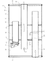
図1に示すマフラ1は、車両に搭載された内燃機関(図示せず)から排出される排ガスの排気流路の一部を構成するものであり、筒状のシェル部材11の両端開口部が後蓋部材12と前蓋部材13とにより閉塞された筐体10を備えている。筐体10の内部は、第1セパレータ21と第2セパレータ22とにより、第1室31、第2室32及び第3室33の3室に区画されている。
(1)上記実施形態では、バタフライ52を閉弁方向へ付勢するための付勢手段として、バタフライ52及び第2リンク部材54を閉弁時の位置関係(角度)に近づける方向に付勢するバネ55を例示したが、これに限定されるものではない。例えば図6(A),(B)に示すように、バネ55を第4回転軸部材74に取り付け、第1リンク部材53及び第2リンク部材54を、閉弁時の位置関係(角度)に近づける方向に付勢するようにしてもよい。また、例えば図7(A),(B)に示すように、バネ55を第2回転軸部材72に取り付け、ステー51及び第1リンク部材53を、閉弁時の位置関係(角度)に近づける方向に付勢するようにしてもよい。
Claims (8)
- 支持体により第1回転軸線を中心に回転移動可能に支持され、排気流路の上流室と下流室とを連通する連通流路を開閉するための弁体と、
前記支持体により第2回転軸線を中心に回転移動可能に支持された第1リンク部材と、
前記弁体により第3回転軸線を中心に回転移動可能に支持された第2リンク部材と、
前記弁体を閉弁方向へ付勢するための付勢部材と、
を備え、
前記第1リンク部材と、前記第2リンク部材とは、第4回転軸線を中心に互いに回転移動可能に接続され、
前記第1回転軸線、前記第2回転軸線、前記第3回転軸線及び前記第4回転軸線は、軸線方向が互いに平行であり、
前記軸線と直交する平面において、前記第2回転軸線と前記第4回転軸線とを結ぶ第1リンク線と、前記第3回転軸線と前記第4回転軸線とを結ぶ第2リンク線と、により形成される角度が180度に達することを防止するストッパ機構が形成されており、
前記第1リンク部材及び前記第2リンク部材は、それぞれ、軸方向両側に形成された2つの側板部と、前記2つの側板部を連結する連結板部と、を備え、
前記ストッパ機構は、前記第1リンク部材の前記連結板部と、前記第2リンク部材の前記2つの側板部と、が当接することにより、前記第1リンク線と、前記第2リンク線とにより形成される角度を制限する
ことを特徴とする排気流路用弁装置。 - 請求項1に記載の排気流路用弁装置であって、
前記第3回転軸線は、前記弁体の先端側に位置している
ことを特徴とする排気流路用弁装置。 - 請求項1又は請求項2に記載の排気流路用弁装置であって、
前記第1回転軸線と前記第3回転軸線との間の距離が、前記第2回転軸線と前記第4回転軸線との間の距離よりも長い
ことを特徴とする排気流路用弁装置。 - 請求項1から請求項3までのいずれか1項に記載の排気流路用弁装置であって、
前記第1回転軸線と前記第3回転軸線との間の距離が、前記第3回転軸線と前記第4回転軸線との間の距離よりも長い
ことを特徴とする排気流路用弁装置。 - 請求項1から請求項4までのいずれか1項に記載の排気流路用弁装置であって、
前記第1回転軸線と前記第3回転軸線との間の距離が、前記第1回転軸線と前記第2回転軸線との間の距離よりも長い
ことを特徴とする排気流路用弁装置。 - 請求項1から請求項5までのいずれか1項に記載の排気流路用弁装置であって、
前記弁体が前記連通流路を閉じた状態で、前記軸線と直交する平面において、前記第1リンク線と前記第2リンク線とにより形成される角度が、前記第2回転軸線と前記第1回転軸線とを結ぶ線と、前記第3回転軸線と前記第1回転軸線とを結ぶ線と、により形成される角度よりも大きい
ことを特徴とする排気流路用弁装置。 - 請求項1から請求項6までのいずれか1項に記載の排気流路用弁装置であって、
前記付勢部材は、前記弁体及び前記第2リンク部材を閉弁時の位置関係に近づける方向に付勢することで、前記弁体を閉弁方向へ付勢する
ことを特徴とする排気流路用弁装置。 - 請求項1から請求項6までのいずれか1項に記載の排気流路用弁装置であって、
前記付勢部材は、前記第1リンク部材及び前記第2リンク部材を閉弁時の位置関係に近づける方向に付勢することで、前記弁体を閉弁方向へ付勢する
ことを特徴とする排気流路用弁装置。
Priority Applications (5)
| Application Number | Priority Date | Filing Date | Title |
|---|---|---|---|
| JP2012037552A JP6017798B2 (ja) | 2012-02-23 | 2012-02-23 | 排気流路用弁装置 |
| CN201380010358.6A CN104246161B (zh) | 2012-02-23 | 2013-02-20 | 排气流路用阀装置 |
| US14/380,104 US9447715B2 (en) | 2012-02-23 | 2013-02-20 | Valve device for exhaust gas flow path |
| PCT/JP2013/054152 WO2013125572A1 (ja) | 2012-02-23 | 2013-02-20 | 排気流路用弁装置 |
| EP13751846.0A EP2818660B1 (en) | 2012-02-23 | 2013-02-20 | Valve device for exhaust gas flow path |
Applications Claiming Priority (1)
| Application Number | Priority Date | Filing Date | Title |
|---|---|---|---|
| JP2012037552A JP6017798B2 (ja) | 2012-02-23 | 2012-02-23 | 排気流路用弁装置 |
Publications (2)
| Publication Number | Publication Date |
|---|---|
| JP2013174131A JP2013174131A (ja) | 2013-09-05 |
| JP6017798B2 true JP6017798B2 (ja) | 2016-11-02 |
Family
ID=49005754
Family Applications (1)
| Application Number | Title | Priority Date | Filing Date |
|---|---|---|---|
| JP2012037552A Active JP6017798B2 (ja) | 2012-02-23 | 2012-02-23 | 排気流路用弁装置 |
Country Status (5)
| Country | Link |
|---|---|
| US (1) | US9447715B2 (ja) |
| EP (1) | EP2818660B1 (ja) |
| JP (1) | JP6017798B2 (ja) |
| CN (1) | CN104246161B (ja) |
| WO (1) | WO2013125572A1 (ja) |
Families Citing this family (19)
| Publication number | Priority date | Publication date | Assignee | Title |
|---|---|---|---|---|
| JP6181564B2 (ja) * | 2014-01-23 | 2017-08-16 | フタバ産業株式会社 | 排気流路用弁装置 |
| CN104847936A (zh) * | 2014-02-14 | 2015-08-19 | 上海天纳克排气系统有限公司 | 控制阀、包括控制阀的机动车辆的排气系统和机动车辆 |
| EP2988040A1 (en) * | 2014-08-20 | 2016-02-24 | JKF Industri A/S | A safety valve and a safety arrangement for a fluid piping system |
| JP6426479B2 (ja) * | 2015-01-08 | 2018-11-21 | フタバ産業株式会社 | 排気流路用弁装置 |
| JP6382725B2 (ja) | 2015-01-08 | 2018-08-29 | フタバ産業株式会社 | 排気流路用弁装置 |
| US9464559B2 (en) | 2015-02-04 | 2016-10-11 | Middleville Tool & Die Co. | Passive exhaust valve assembly and forming method |
| JP6483469B2 (ja) * | 2015-02-20 | 2019-03-13 | フタバ産業株式会社 | マフラ |
| DE102015110199A1 (de) | 2015-06-25 | 2016-12-29 | Eberspächer Exhaust Technology GmbH & Co. KG | Abgasschalldämpfer |
| WO2017111980A1 (en) | 2015-12-24 | 2017-06-29 | Middleville Tool & Die Co. | Passive exhaust valve with floating spring stop |
| CN108779885B (zh) * | 2016-01-15 | 2020-04-17 | 米德维尔工具模具公司 | 具有交叠滑配接头的被动排出阀组件及形成和安装的方法 |
| WO2017126127A1 (ja) * | 2016-01-22 | 2017-07-27 | フタバ産業株式会社 | マフラ |
| WO2017126126A1 (ja) * | 2016-01-22 | 2017-07-27 | フタバ産業株式会社 | 排気流路用弁装置 |
| JP6633660B2 (ja) * | 2016-02-15 | 2020-01-22 | フタバ産業株式会社 | 軸封装置 |
| US9982794B2 (en) | 2016-08-05 | 2018-05-29 | Tenneco Automotive Operating Company Inc. | Passive exhaust valve with external torsion spring |
| US9982793B2 (en) * | 2016-08-05 | 2018-05-29 | Tenneco Automotive Operating Company Inc. | Passive exhaust valve with dual torsion spring |
| CN106594325B (zh) * | 2017-02-06 | 2018-11-20 | 广东永泉阀门科技有限公司 | 减压型倒流防止器 |
| CN106594332B (zh) * | 2017-02-06 | 2018-11-20 | 广东永泉阀门科技有限公司 | 减压型防倒流止回阀 |
| JP7059570B2 (ja) * | 2017-11-09 | 2022-04-26 | スズキ株式会社 | 車両の排気装置 |
| US10788136B1 (en) * | 2019-03-29 | 2020-09-29 | Tenneco Automotive Operating Company Inc. | Damper valve assembly |
Family Cites Families (18)
| Publication number | Priority date | Publication date | Assignee | Title |
|---|---|---|---|---|
| US2394471A (en) * | 1944-04-22 | 1946-02-05 | Herman L Paul | Valve |
| US3182951A (en) * | 1962-01-18 | 1965-05-11 | Kenneth L Spencer | Pivoted valve |
| US4264085A (en) * | 1979-04-20 | 1981-04-28 | Frank Volin | Wheelchair convenience attachments |
| JPS59163183A (ja) * | 1983-03-03 | 1984-09-14 | 株式会社 東京タツノ | 地下タンクに連結された配管装置 |
| DE3541192C1 (de) * | 1985-11-21 | 1986-11-27 | Karl Dipl.-Ing.(FH) 4040 Neuss Weinhold | Klappenventil |
| JP2586177Y2 (ja) * | 1993-11-12 | 1998-12-02 | 株式会社クボタ | フラップ弁 |
| US5947152A (en) | 1995-08-11 | 1999-09-07 | Grinnell Corporation | Check valve and backflow preventer |
| JPH09195749A (ja) * | 1996-01-16 | 1997-07-29 | Futaba Sangyo Kk | 内燃機関用マフラ |
| JPH10137070A (ja) * | 1996-11-13 | 1998-05-26 | Ikeda Bussan Co Ltd | フットレスト機構 |
| JPH10141040A (ja) * | 1996-11-14 | 1998-05-26 | Umex:Kk | 内燃機関用消音装置 |
| JP4141601B2 (ja) * | 1999-09-24 | 2008-08-27 | カルソニックカンセイ株式会社 | 自動車用制御型消音器 |
| JP2002180446A (ja) * | 2000-12-14 | 2002-06-26 | Kubota Corp | フラップ弁 |
| US6443181B1 (en) * | 2000-12-28 | 2002-09-03 | Hunter Innovations, Inc. | Backflow prevention apparatus |
| JP4612233B2 (ja) * | 2001-06-22 | 2011-01-12 | フタバ産業株式会社 | 内燃機関用マフラ |
| CN1991138A (zh) * | 2005-12-31 | 2007-07-04 | 张庆义 | 一种汽车消声器总成 |
| CN200978702Y (zh) * | 2006-11-16 | 2007-11-21 | 上海通用汽车有限公司 | 汽车排气消声器 |
| JP2008175113A (ja) * | 2007-01-17 | 2008-07-31 | Calsonic Kansei Corp | 排気制御弁 |
| JP2008255879A (ja) * | 2007-04-04 | 2008-10-23 | Nissan Motor Co Ltd | 車両用排気音制御方法及び車両用排気音制御装置 |
-
2012
- 2012-02-23 JP JP2012037552A patent/JP6017798B2/ja active Active
-
2013
- 2013-02-20 EP EP13751846.0A patent/EP2818660B1/en active Active
- 2013-02-20 US US14/380,104 patent/US9447715B2/en active Active
- 2013-02-20 WO PCT/JP2013/054152 patent/WO2013125572A1/ja active Application Filing
- 2013-02-20 CN CN201380010358.6A patent/CN104246161B/zh active Active
Also Published As
| Publication number | Publication date |
|---|---|
| CN104246161B (zh) | 2017-05-17 |
| US9447715B2 (en) | 2016-09-20 |
| WO2013125572A1 (ja) | 2013-08-29 |
| CN104246161A (zh) | 2014-12-24 |
| JP2013174131A (ja) | 2013-09-05 |
| EP2818660A1 (en) | 2014-12-31 |
| EP2818660A4 (en) | 2015-10-07 |
| US20150027566A1 (en) | 2015-01-29 |
| EP2818660B1 (en) | 2017-03-29 |
Similar Documents
| Publication | Publication Date | Title |
|---|---|---|
| JP6017798B2 (ja) | 排気流路用弁装置 | |
| EP2221458B1 (en) | Muffler | |
| JP2010521615A (ja) | 排気システム用スナップ作動弁 | |
| JPH1181977A (ja) | 消音器 | |
| WO2016035329A1 (ja) | ターボチャージャの排気タービン | |
| JP2014218945A (ja) | 流量可変バルブ機構及び過給機 | |
| WO2015166707A1 (ja) | 消音器 | |
| JP6211901B2 (ja) | 排気流路用弁装置 | |
| JP4775355B2 (ja) | 消音器用バルブ装置 | |
| JP6491362B2 (ja) | マフラ | |
| US11661871B2 (en) | Muffler for vehicle | |
| JP6675246B2 (ja) | バタフライバルブ構造 | |
| JP6596394B2 (ja) | 消音器 | |
| JP7274310B2 (ja) | 消音器 | |
| JP4451728B2 (ja) | 消音器 | |
| JP2516297Y2 (ja) | 自動車用消音器内部のガス流路切換え装置 | |
| JP4935615B2 (ja) | 消音器用バルブ装置 | |
| JP4361355B2 (ja) | 内燃機関用消音器 | |
| JP6382725B2 (ja) | 排気流路用弁装置 | |
| JP3972626B2 (ja) | 車両用排気消音装置 | |
| JP5616661B2 (ja) | 排気流量制御弁 | |
| JP2006316765A (ja) | 内燃機関用マフラ | |
| JP2010133369A (ja) | 排気可変マフラー | |
| JP2014137015A (ja) | 内燃機関の流路切替装置 | |
| JP2013087677A (ja) | 可変バルブ機構 |
Legal Events
| Date | Code | Title | Description |
|---|---|---|---|
| A621 | Written request for application examination |
Free format text: JAPANESE INTERMEDIATE CODE: A621 Effective date: 20150202 |
|
| A131 | Notification of reasons for refusal |
Free format text: JAPANESE INTERMEDIATE CODE: A131 Effective date: 20151110 |
|
| A521 | Request for written amendment filed |
Free format text: JAPANESE INTERMEDIATE CODE: A523 Effective date: 20151228 |
|
| A131 | Notification of reasons for refusal |
Free format text: JAPANESE INTERMEDIATE CODE: A131 Effective date: 20160531 |
|
| A521 | Request for written amendment filed |
Free format text: JAPANESE INTERMEDIATE CODE: A523 Effective date: 20160725 |
|
| TRDD | Decision of grant or rejection written | ||
| A01 | Written decision to grant a patent or to grant a registration (utility model) |
Free format text: JAPANESE INTERMEDIATE CODE: A01 Effective date: 20160906 |
|
| A61 | First payment of annual fees (during grant procedure) |
Free format text: JAPANESE INTERMEDIATE CODE: A61 Effective date: 20160929 |
|
| R150 | Certificate of patent or registration of utility model |
Ref document number: 6017798 Country of ref document: JP Free format text: JAPANESE INTERMEDIATE CODE: R150 |
|
| R250 | Receipt of annual fees |
Free format text: JAPANESE INTERMEDIATE CODE: R250 |
|
| R250 | Receipt of annual fees |
Free format text: JAPANESE INTERMEDIATE CODE: R250 |
|
| R250 | Receipt of annual fees |
Free format text: JAPANESE INTERMEDIATE CODE: R250 |
|
| R250 | Receipt of annual fees |
Free format text: JAPANESE INTERMEDIATE CODE: R250 |
|
| R250 | Receipt of annual fees |
Free format text: JAPANESE INTERMEDIATE CODE: R250 |