EP2818660A1 - Valve device for exhaust gas flow path - Google Patents
Valve device for exhaust gas flow path Download PDFInfo
- Publication number
- EP2818660A1 EP2818660A1 EP13751846.0A EP13751846A EP2818660A1 EP 2818660 A1 EP2818660 A1 EP 2818660A1 EP 13751846 A EP13751846 A EP 13751846A EP 2818660 A1 EP2818660 A1 EP 2818660A1
- Authority
- EP
- European Patent Office
- Prior art keywords
- rotation axis
- valve
- link
- link member
- flow path
- Prior art date
- Legal status (The legal status is an assumption and is not a legal conclusion. Google has not performed a legal analysis and makes no representation as to the accuracy of the status listed.)
- Granted
Links
Images


Classifications
-
- F—MECHANICAL ENGINEERING; LIGHTING; HEATING; WEAPONS; BLASTING
- F01—MACHINES OR ENGINES IN GENERAL; ENGINE PLANTS IN GENERAL; STEAM ENGINES
- F01N—GAS-FLOW SILENCERS OR EXHAUST APPARATUS FOR MACHINES OR ENGINES IN GENERAL; GAS-FLOW SILENCERS OR EXHAUST APPARATUS FOR INTERNAL COMBUSTION ENGINES
- F01N1/00—Silencing apparatus characterised by method of silencing
- F01N1/16—Silencing apparatus characterised by method of silencing by using movable parts
- F01N1/168—Silencing apparatus characterised by method of silencing by using movable parts for controlling or modifying silencing characteristics only
-
- F—MECHANICAL ENGINEERING; LIGHTING; HEATING; WEAPONS; BLASTING
- F01—MACHINES OR ENGINES IN GENERAL; ENGINE PLANTS IN GENERAL; STEAM ENGINES
- F01N—GAS-FLOW SILENCERS OR EXHAUST APPARATUS FOR MACHINES OR ENGINES IN GENERAL; GAS-FLOW SILENCERS OR EXHAUST APPARATUS FOR INTERNAL COMBUSTION ENGINES
- F01N1/00—Silencing apparatus characterised by method of silencing
- F01N1/08—Silencing apparatus characterised by method of silencing by reducing exhaust energy by throttling or whirling
- F01N1/084—Silencing apparatus characterised by method of silencing by reducing exhaust energy by throttling or whirling the gases flowing through the silencer two or more times longitudinally in opposite directions, e.g. using parallel or concentric tubes
-
- F—MECHANICAL ENGINEERING; LIGHTING; HEATING; WEAPONS; BLASTING
- F01—MACHINES OR ENGINES IN GENERAL; ENGINE PLANTS IN GENERAL; STEAM ENGINES
- F01N—GAS-FLOW SILENCERS OR EXHAUST APPARATUS FOR MACHINES OR ENGINES IN GENERAL; GAS-FLOW SILENCERS OR EXHAUST APPARATUS FOR INTERNAL COMBUSTION ENGINES
- F01N1/00—Silencing apparatus characterised by method of silencing
- F01N1/08—Silencing apparatus characterised by method of silencing by reducing exhaust energy by throttling or whirling
- F01N1/086—Silencing apparatus characterised by method of silencing by reducing exhaust energy by throttling or whirling having means to impart whirling motion to the gases
- F01N1/088—Silencing apparatus characterised by method of silencing by reducing exhaust energy by throttling or whirling having means to impart whirling motion to the gases using vanes arranged on gas flow path or gas flow tubes with tangentially directed apertures
-
- F—MECHANICAL ENGINEERING; LIGHTING; HEATING; WEAPONS; BLASTING
- F01—MACHINES OR ENGINES IN GENERAL; ENGINE PLANTS IN GENERAL; STEAM ENGINES
- F01N—GAS-FLOW SILENCERS OR EXHAUST APPARATUS FOR MACHINES OR ENGINES IN GENERAL; GAS-FLOW SILENCERS OR EXHAUST APPARATUS FOR INTERNAL COMBUSTION ENGINES
- F01N1/00—Silencing apparatus characterised by method of silencing
- F01N1/16—Silencing apparatus characterised by method of silencing by using movable parts
- F01N1/165—Silencing apparatus characterised by method of silencing by using movable parts for adjusting flow area
-
- F—MECHANICAL ENGINEERING; LIGHTING; HEATING; WEAPONS; BLASTING
- F01—MACHINES OR ENGINES IN GENERAL; ENGINE PLANTS IN GENERAL; STEAM ENGINES
- F01N—GAS-FLOW SILENCERS OR EXHAUST APPARATUS FOR MACHINES OR ENGINES IN GENERAL; GAS-FLOW SILENCERS OR EXHAUST APPARATUS FOR INTERNAL COMBUSTION ENGINES
- F01N1/00—Silencing apparatus characterised by method of silencing
- F01N1/16—Silencing apparatus characterised by method of silencing by using movable parts
- F01N1/166—Silencing apparatus characterised by method of silencing by using movable parts for changing gas flow path through the silencer or for adjusting the dimensions of a chamber or a pipe
-
- F—MECHANICAL ENGINEERING; LIGHTING; HEATING; WEAPONS; BLASTING
- F01—MACHINES OR ENGINES IN GENERAL; ENGINE PLANTS IN GENERAL; STEAM ENGINES
- F01N—GAS-FLOW SILENCERS OR EXHAUST APPARATUS FOR MACHINES OR ENGINES IN GENERAL; GAS-FLOW SILENCERS OR EXHAUST APPARATUS FOR INTERNAL COMBUSTION ENGINES
- F01N1/00—Silencing apparatus characterised by method of silencing
- F01N1/16—Silencing apparatus characterised by method of silencing by using movable parts
- F01N1/18—Silencing apparatus characterised by method of silencing by using movable parts having rotary movement
-
- F—MECHANICAL ENGINEERING; LIGHTING; HEATING; WEAPONS; BLASTING
- F16—ENGINEERING ELEMENTS AND UNITS; GENERAL MEASURES FOR PRODUCING AND MAINTAINING EFFECTIVE FUNCTIONING OF MACHINES OR INSTALLATIONS; THERMAL INSULATION IN GENERAL
- F16K—VALVES; TAPS; COCKS; ACTUATING-FLOATS; DEVICES FOR VENTING OR AERATING
- F16K15/00—Check valves
- F16K15/02—Check valves with guided rigid valve members
- F16K15/03—Check valves with guided rigid valve members with a hinged closure member or with a pivoted closure member
- F16K15/033—Check valves with guided rigid valve members with a hinged closure member or with a pivoted closure member spring-loaded
-
- F—MECHANICAL ENGINEERING; LIGHTING; HEATING; WEAPONS; BLASTING
- F01—MACHINES OR ENGINES IN GENERAL; ENGINE PLANTS IN GENERAL; STEAM ENGINES
- F01N—GAS-FLOW SILENCERS OR EXHAUST APPARATUS FOR MACHINES OR ENGINES IN GENERAL; GAS-FLOW SILENCERS OR EXHAUST APPARATUS FOR INTERNAL COMBUSTION ENGINES
- F01N2240/00—Combination or association of two or more different exhaust treating devices, or of at least one such device with an auxiliary device, not covered by indexing codes F01N2230/00 or F01N2250/00, one of the devices being
- F01N2240/36—Combination or association of two or more different exhaust treating devices, or of at least one such device with an auxiliary device, not covered by indexing codes F01N2230/00 or F01N2250/00, one of the devices being an exhaust flap
-
- F—MECHANICAL ENGINEERING; LIGHTING; HEATING; WEAPONS; BLASTING
- F01—MACHINES OR ENGINES IN GENERAL; ENGINE PLANTS IN GENERAL; STEAM ENGINES
- F01N—GAS-FLOW SILENCERS OR EXHAUST APPARATUS FOR MACHINES OR ENGINES IN GENERAL; GAS-FLOW SILENCERS OR EXHAUST APPARATUS FOR INTERNAL COMBUSTION ENGINES
- F01N2290/00—Movable parts or members in exhaust systems for other than for control purposes
- F01N2290/08—Movable parts or members in exhaust systems for other than for control purposes with oscillating or vibrating movement
- F01N2290/10—Movable parts or members in exhaust systems for other than for control purposes with oscillating or vibrating movement actuated by pressure of exhaust gases, e.g. exhaust pulses
-
- Y—GENERAL TAGGING OF NEW TECHNOLOGICAL DEVELOPMENTS; GENERAL TAGGING OF CROSS-SECTIONAL TECHNOLOGIES SPANNING OVER SEVERAL SECTIONS OF THE IPC; TECHNICAL SUBJECTS COVERED BY FORMER USPC CROSS-REFERENCE ART COLLECTIONS [XRACs] AND DIGESTS
- Y10—TECHNICAL SUBJECTS COVERED BY FORMER USPC
- Y10T—TECHNICAL SUBJECTS COVERED BY FORMER US CLASSIFICATION
- Y10T137/00—Fluid handling
- Y10T137/7722—Line condition change responsive valves
- Y10T137/7837—Direct response valves [i.e., check valve type]
- Y10T137/7898—Pivoted valves
Definitions
- the present invention relates to a valve device for an exhaust gas flow path.
- Patent Document 1 there is disclosed a valve device disposed in a muffler for an internal combustion engine. An inside of the muffler is partitioned into an upstream chamber and a downstream chamber by a separator, and the valve device is provided to the separator to open and close an opening communicating the upstream chamber and the downstream chamber with each other.
- a valve body capable of closing the opening is supported by a support body so as to be rotatable about a rotation axis, and the valve body is biased in a valve closed direction by a coil spring.
- an acting force exerted on the valve body by a pressure in the upstream chamber is smaller than an acting force exerted on the valve body by the sum of the biasing force of the coil spring and the pressure in the downstream chamber.
- the valve device is in a valve closed state in which the opening is closed.
- the acting force exerted on the valve body by the pressure in the upstream chamber becomes larger than the acting force exerted on the valve body by the sum of the biasing force of the coil spring and the pressure in the downstream chamber.
- the valve device is brought into a valve open state in which the valve body is spaced apart from the opening to thereby open the opening.
- Patent Document 1 Japanese Unexamined Patent Application Publication No. H09-195749
- Such a valve device for an exhaust gas flow path is required to have a noise reduction function to reduce noise by closing the communicating flow path when the internal combustion engine is in a low revolution state, while being required to have a pressure loss reduction function to reduce pressure loss by opening the communicating flow path when the internal combustion engine is in a high revolution state.
- the more forward the valve body moves in a valve open direction the larger the biasing force of the coil spring becomes. Therefore, when the spring force of the coil spring is designed to be stronger with an emphasis on the noise reduction function at the time of low revolution, the pressure loss reduction function at the time of high revolution is impaired. In contrast, when the spring force of the coil spring is designed to be weaker with an emphasis on the pressure loss reduction function at the time of high revolution, the noise reduction function at the time of low revolution is impaired.
- valve device for an exhaust gas flow path it is preferred for the valve device for an exhaust gas flow path to have both an improved noise reduction function at the time of low revolution and an improved pressure loss reduction function at the time of high revolution.
- a valve device for an exhaust gas flow path includes a valve body that is supported by a support body so as to be rotationally movable about a first rotation axis and that opens and closes a communicating flow path that communicates an upstream chamber and a downstream chamber in an exhaust gas flow path with each other, a first link member supported by the support body so as to be rotationally movable about a second rotation axis, a second link member supported by the valve body so as to be rotationally movable about a third rotation axis, and a biasing member to bias the valve body in a valve closed direction.
- the first link member and the second link member are connected to each other so as to be mutually rotationally movable about a fourth rotation axis.
- the first rotation axis, the second rotation axis, the third rotation axis, and the fourth rotation axis are parallel to one another in an axial direction.
- an angle formed by a first link line connecting the second rotation axis and the fourth rotation axis to each other and a second link line connecting the third rotation axis and the fourth rotation axis to each other is formed to be the largest in a state in which the communicating flow path is closed by the valve body.
- the support body, the valve body, the first link member, and the second link member form a toggle mechanism of a link type. Therefore, in the state in which the communicating flow path is closed by the valve body (a valve closed state), the closer to 180 degrees (a state in which the first link line and the second link line are arranged in a straight line) the angle formed by the first link line and the second link line is, the stronger external force is required to rotationally move the valve body in a valve open direction. Accordingly, it is possible to make the external force required to open the valve body greater, while making a biasing force of the biasing member smaller, compared with a conventional configuration in which a valve body is kept in a valve closed state solely by means of a biasing member. As a result, it is possible to improve a noise reduction function at the time of low revolution of an internal combustion engine, as well as a pressure loss reduction function at the time of high revolution of the internal combustion engine.
- the valve device for an exhaust gas flow path may be provided with a stopper mechanism to limit the angle formed by the first link line and the second link line to an angle smaller than 180 degrees. According to this configuration, a problem that the valve body cannot be normally opened when the angle formed by the first link line and the second link line has reached 180 degrees can be made less likely to occur.
- the stopper mechanism may limit the angle formed by the first link line and the second link line to an angle smaller than 180 degrees by abutment of a first stopper portion provided on the first link member and a second stopper portion provided on the second link member against each other. According to this configuration, it is possible to reduce an influence of factors such as variations in parts dimensions and rattling of parts on a limit angle. As a result, the angle formed by the first link line and the second link line in the state in which the communicating flow path is closed by the valve body can be designed to be an angle closer to 180 degrees. Thus, it is possible to improve performance to keep a valve closed state against an external force.
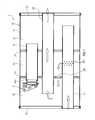
- a muffler 1 shown in FIG. 1 forms a part of an exhaust gas flow path through which flows an exhaust gas discharged from an in-vehicle internal combustion engine (not shown).
- the muffler 1 includes a casing 10, in which openings at both ends of a cylindrical shell member 11 are closed by a rear lid member 12 and a front lid member 13.
- An inside of the casing 10 is partitioned into three chambers, i.e., a first chamber 31, a second chamber 32, and a third chamber 33 by a first separator 21 and a second separator 22.
- the first chamber 31 is provided between the rear lid member 12 and the first separator 21.
- the second chamber 32 is provided between the first separator 21 and the second separator 22.
- the third chamber 33 is provided between the second separator 22 and the front lid member 13.
- the second separator 22 has a communication hole 221 provided therein that communicates the second chamber 32 and the third chamber 33 with each other.
- the muffler 1 further includes an inlet pipe 41 through which the exhaust gas from the internal combustion engine is introduced.
- the inlet pipe 41 is provided so as to penetrate through the front lid member 13, the second separator 22, and the first separator 21 and to open to the first chamber 31 at its downstream-side end.
- the muffler 1 further includes an outlet pipe 42 to be connected to a not-shown tailpipe to discharge the exhaust gas.
- the outlet pipe 42 is provided so as to penetrate through the rear lid member 12, the first separator 21, and the second separator 22 and to open to the third chamber 33 at its upstream-side end.
- the muffler 1 further includes an inner pipe 43 to form a communicating flow path that communicates the first chamber 31 and the third chamber 33 with each other.
- the inner pipe 43 is provided so as to penetrate through the first separator 21 and the second separator 22, to open to the first chamber 31 at its upstream-side end, and to open to the third chamber 33 at its downstream-side end.
- the inner pipe 43 has, at the downstream-side end thereof, a valve device 5 mounted to open and close an opening 431 provided at the downstream-side end of the inner pipe 43.
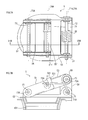
- the valve device 5 includes a stay 51, a butterfly valve 52, a first link member 53, and a second link member 54.
- the stay 51 is fixed in position with respect to the opening 431 provided at the downstream-side end of the inner pipe 43.
- Each of the butterfly valve 52 and the first link member 53 is supported at one end thereof by the stay 51.
- the second link member 54 is supported at one end thereof by the butterfly valve 52.
- the butterfly valve 52 is shaped so as to be able to close the opening 431 of the inner pipe 43, and is connected at an end thereof to the stay 51 via a first rotation axis member 71. Specifically, the butterfly valve 52 is supported by the stay 51 so as to be rotationally movable about a rotation axis (hereinafter referred to as a "first rotation axis 71A") of the first rotation axis member 71, and opens and closes the opening 431 of the inner pipe 43 according to its rotational position.
- first rotation axis 71A rotationally axis
- the first link member 53 is connected at an end thereof to the stay 51 via a second rotation axis member 72. Specifically, the first link member 53 is supported by the stay 51 so as to be rotationally movable about a rotation axis (hereinafter referred to as a "second rotation axis 72A") of the second rotation axis member 72.
- a rotation axis hereinafter referred to as a "second rotation axis 72A"
- the second link member 54 is connected at an end thereof to an upper surface (a portion that stands up with valve opening) of the butterfly valve 52 via a third rotation axis member 73. Specifically, the second link member 54 is supported by the butterfly valve 52 so as to be rotationally movable about a rotation axis (hereinafter referred to as a "third rotation axis 73A") of the third rotation axis member 73.
- the first link member 53 and the second link member 54 are connected to each other via a fourth rotation axis member 74.
- the first link member 53 and the second link member 54 are connected to each other so as to be mutually rotationally movable about a rotation axis (hereinafter referred to as a "fourth rotation axis 74A") of the fourth rotation axis member 74.
- the first rotation axis 71 A, the second rotation axis 72A, the third rotation axis 73A, and the fourth rotation axis 74A are parallel to one another in an axial direction.
- the stay 51, the butterfly valve 52, the first link member 53, and the second link member 54 form a toggle mechanism of a link type.
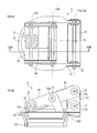
- the butterfly valve 52 is rotationally movable from a valve closed state ( FIGS. 2A and 2B ) in which the opening 431 of the inner pipe 43 is closed to a valve open state ( FIGS. 3A and 3B ) in which the opening 431 of the inner pipe 43 is open.
- the valve device 5 further includes a spring 55 to bias the butterfly valve 52 in a valve closed direction.
- the spring 55 is mounted to the third rotation axis member 73, and applies a biasing force in a direction to bring the butterfly valve 52 and the second link member 54 closer to a positional relationship (angle) in a valve closed state. Accordingly, in its regular state (a state in which no external force to open the butterfly valve 52 is applied), the butterfly valve 52 is in a valve closed state.
- the first link member 53 and the second link member 54 are designed to be arranged in an approximately straight line in a valve closed state.
- an angle ⁇ formed by a first link line L1 connecting the second rotation axis 72A (specifically, an intersection between the axis and the plane, and the same applies hereafter) and the fourth rotation axis 74A to each other and a second link line L2 connecting the third rotation axis 73A and the fourth rotation axis 74A to each other is an angle close to 180 degrees in a valve closed state ( FIGS. 2A and 2B ).
- the stopper mechanism includes a first stopper portion 531 provided on the first link member 53 and a second stopper portion 541 provided on the second link member 54.
- the angle ⁇ formed by the first link line L1 and the second link line L2 is limited to an angle smaller than 180 degrees by abutment of the first stopper portion 531 and the second stopper portion 541 against each other.
- the first link member 53 includes side plate portions 532 and 533 provided on its both sides in an axial direction, and a coupling plate portion 534 coupling the side plate portions 532 and 533 to each other.
- the second link member includes side plate portions 542 and 543 provided on its both sides in an axial direction, and a coupling plate portion 544 coupling the side plate portions 542 and 543 to each other.
- it is configured such that the coupling plate portion 534 of the first link member 53 and the side plate portions 532 and 533 of the second link member abut against each other. That is, the coupling plate portion 534 of the first link member 53 functions as the first stopper portion 531, and the side plate portions 532 and 533 of the second link member function as the second stopper portion 541.
- the exhaust gas from the internal combustion engine is introduced into the second chamber 32 via the plurality of through-holes 411 formed in the inlet pipe 41, as indicated by arrows in FIG. 1 , and noise is silenced by an expansion effect and a resonance effect.
- the exhaust gas in the second chamber 32 is introduced into the third chamber 33 via the communication hole 221 formed in the second separator 22, and noise is further silenced by an expansion effect and a resonance effect.
- the exhaust gas in the third chamber 33 pressure pulsation of which has been smoothed and noise of which has been silenced, is discharged to the outside via the outlet pipe 42.
- a pressure difference between that in the first chamber 31 and that in the third chamber 33 is small.
- an acting force exerted on the butterfly valve 52 of the valve device 5 by the pressure in the first chamber 31 is smaller than an acting force exerted on the butterfly valve 52 of the valve device 5 by a load applied by the toggle mechanism and the spring 55 in the valve device 5 and the pressure in the third chamber 33. Accordingly, the opening 431 of the inner pipe 43 is closed by the butterfly valve 52.
- the acting force exerted on the butterfly valve 52 of the valve device 5 by the pressure in the first chamber 31 becomes larger than the acting force exerted on the butterfly valve 52 of the valve device 5 by the load applied by the toggle mechanism and the spring 55 in the valve device 5 and the pressure in the third chamber 33.
- the butterfly valve 52 is spaced apart from the opening 431 of the inner pipe 43 against the latter acting force to open the opening 431, and the first chamber 31 and the third chamber 33 thereby communicate with each other via the inner pipe 43.
- the opening 431 of the inner pipe 43 is opened and a communicating flow path (a bypass flow path) is formed separately when the pressure in the first chamber 31 is increased to the predetermined pressure or more, and thus, even when an amount of the exhaust gas introduced into the first chamber 31 is increased, such exhaust gas is promptly discharged to the third chamber 33. Consequently, the pressure in the first chamber 31 is not increased, and even when the pressure of the exhaust gas from the internal combustion engine is increased, an increase in back pressure thereof can be suppressed. Furthermore, even when a flow rate of the exhaust gas is increased, an increase in pressure in the muffler 1 can be suppressed and, thus, airflow noise is reduced.
- the stay 51, the butterfly valve 52, the first link member 53, and the second link member 54 form the toggle mechanism of a link type. Since the angle ⁇ formed by the first link line L1 and the second link line L2 in a valve closed state is an angle close to 180 degrees, a strong external force is required to rotationally move the butterfly valve 52 in the valve open direction. Accordingly, it is possible to make the external force required to open the butterfly valve 52 greater, while weakening a biasing force of the spring 55, compared with a conventional configuration in which a butterfly valve is kept in a valve closed state solely by means of a spring.
- the spring 55 has linear characteristics such that the larger the degree of opening of the butterfly valve 52 is, the larger the moment becomes (a broken line L3), and the toggle mechanism has characteristics such that the moment becomes largest when the butterfly valve 52 is in a valve closed state (a solid line L4). Therefore, in the configuration according to the present embodiment, in which the butterfly valve 52 is kept in a valve closed state by means of the toggle mechanism and the spring 55, it is possible to decrease the moment in a state in which the degree of opening of the butterfly valve 52 is larger, while increasing the moment in a state in which the degree of opening is smaller.
- valve device 5 Since the valve device 5 has the stopper mechanism provide therein, a problem that the butterfly valve 52 cannot be normally opened when the angle ⁇ formed by the first link line L1 and the second link line L2 has reached 180 degrees can be made less likely to occur.
- a stopper mechanism is especially effective to make the angle ⁇ formed by the first link line L1 and the second link line L2 in a valve closed state closer to 180 degrees. This is because it is assumed that the closer to 180 degrees the angle ⁇ in a valve closed state is, the more likely an actually formed angle under the influence of variations in parts dimensions, rattling of parts, or the like reaches 180 degrees.
- the stopper mechanism according to the present embodiment is provided to the first link member 53 and the second link member 54 themselves that form the first link line L1 and the second link line L2, respectively, and thus, it is possible to reduce the influence of factors such as variations in parts dimensions and rattling of parts on a limit angle.
- the angle ⁇ in a valve closed state can be designed to be an angle closer to 180 degrees, and a configuration with high performance to keep a valve closed state against an external force can be achieved.
- the first chamber 31 corresponds to an example of an upstream chamber
- the third chamber 33 corresponds to an example of a downstream chamber.
- the valve device 5 corresponds to an example of a valve device for an exhaust gas flow path
- the stay 51 corresponds to an example of a support body
- the butterfly valve 52 corresponds to an example of a valve body
- the first link member 53 and the second link member 54 correspond to an example of a first link member and a second link member, respectively
- the spring 55 corresponds to an example of a biasing member.
- the first rotation axis 71A to the fourth rotation axis 74A correspond to an example of a first rotation axis to a fourth rotation axis, respectively, and the first link line L1 and the second link line L2 correspond to an example of a first link line and a second link line, respectively.
Abstract

Description
- This international application claims the benefit of Japanese Patent Application No.
2012-037552 filed February 23, 2012 2012-037552 - The present invention relates to a valve device for an exhaust gas flow path.
- There is known a valve device for an exhaust gas flow path to open and close a communicating flow path that communicates an upstream chamber and a downstream chamber with each other in an exhaust gas flow path for an in-vehicle internal combustion engine. In
Patent Document 1 for example, there is disclosed a valve device disposed in a muffler for an internal combustion engine. An inside of the muffler is partitioned into an upstream chamber and a downstream chamber by a separator, and the valve device is provided to the separator to open and close an opening communicating the upstream chamber and the downstream chamber with each other. In the valve device, a valve body capable of closing the opening is supported by a support body so as to be rotatable about a rotation axis, and the valve body is biased in a valve closed direction by a coil spring. - When the number of revolutions of the internal combustion engine is low, an acting force exerted on the valve body by a pressure in the upstream chamber is smaller than an acting force exerted on the valve body by the sum of the biasing force of the coil spring and the pressure in the downstream chamber. Thus, the valve device is in a valve closed state in which the opening is closed. In contrast, when the number of revolutions of the internal combustion engine is increased, the acting force exerted on the valve body by the pressure in the upstream chamber becomes larger than the acting force exerted on the valve body by the sum of the biasing force of the coil spring and the pressure in the downstream chamber. Thus, the valve device is brought into a valve open state in which the valve body is spaced apart from the opening to thereby open the opening.
- Patent Document 1: Japanese Unexamined Patent Application Publication No.
H09-195749 - Such a valve device for an exhaust gas flow path is required to have a noise reduction function to reduce noise by closing the communicating flow path when the internal combustion engine is in a low revolution state, while being required to have a pressure loss reduction function to reduce pressure loss by opening the communicating flow path when the internal combustion engine is in a high revolution state. However, in the above-described configuration described in
Patent Document 1, the more forward the valve body moves in a valve open direction, the larger the biasing force of the coil spring becomes. Therefore, when the spring force of the coil spring is designed to be stronger with an emphasis on the noise reduction function at the time of low revolution, the pressure loss reduction function at the time of high revolution is impaired. In contrast, when the spring force of the coil spring is designed to be weaker with an emphasis on the pressure loss reduction function at the time of high revolution, the noise reduction function at the time of low revolution is impaired. - In one aspect of the present invention, it is preferred for the valve device for an exhaust gas flow path to have both an improved noise reduction function at the time of low revolution and an improved pressure loss reduction function at the time of high revolution.
- A valve device for an exhaust gas flow path according to the present invention includes a valve body that is supported by a support body so as to be rotationally movable about a first rotation axis and that opens and closes a communicating flow path that communicates an upstream chamber and a downstream chamber in an exhaust gas flow path with each other, a first link member supported by the support body so as to be rotationally movable about a second rotation axis, a second link member supported by the valve body so as to be rotationally movable about a third rotation axis, and a biasing member to bias the valve body in a valve closed direction. The first link member and the second link member are connected to each other so as to be mutually rotationally movable about a fourth rotation axis. The first rotation axis, the second rotation axis, the third rotation axis, and the fourth rotation axis are parallel to one another in an axial direction. In a plane orthogonal to the axes, an angle formed by a first link line connecting the second rotation axis and the fourth rotation axis to each other and a second link line connecting the third rotation axis and the fourth rotation axis to each other is formed to be the largest in a state in which the communicating flow path is closed by the valve body.
- According to such a configuration, the support body, the valve body, the first link member, and the second link member form a toggle mechanism of a link type. Therefore, in the state in which the communicating flow path is closed by the valve body (a valve closed state), the closer to 180 degrees (a state in which the first link line and the second link line are arranged in a straight line) the angle formed by the first link line and the second link line is, the stronger external force is required to rotationally move the valve body in a valve open direction. Accordingly, it is possible to make the external force required to open the valve body greater, while making a biasing force of the biasing member smaller, compared with a conventional configuration in which a valve body is kept in a valve closed state solely by means of a biasing member. As a result, it is possible to improve a noise reduction function at the time of low revolution of an internal combustion engine, as well as a pressure loss reduction function at the time of high revolution of the internal combustion engine.
- The valve device for an exhaust gas flow path may be provided with a stopper mechanism to limit the angle formed by the first link line and the second link line to an angle smaller than 180 degrees. According to this configuration, a problem that the valve body cannot be normally opened when the angle formed by the first link line and the second link line has reached 180 degrees can be made less likely to occur.
- The stopper mechanism may limit the angle formed by the first link line and the second link line to an angle smaller than 180 degrees by abutment of a first stopper portion provided on the first link member and a second stopper portion provided on the second link member against each other. According to this configuration, it is possible to reduce an influence of factors such as variations in parts dimensions and rattling of parts on a limit angle. As a result, the angle formed by the first link line and the second link line in the state in which the communicating flow path is closed by the valve body can be designed to be an angle closer to 180 degrees. Thus, it is possible to improve performance to keep a valve closed state against an external force.
-
-
FIG. 1 is a sectional view of a muffler in which a valve device is in a valve closed state. -
FIG. 2A is a plan view of the valve device according to the embodiment in a valve closed state, andFIG. 2B is a sectional view thereof taken along line IIB-IIB. -
FIG. 3A is a plan view of the valve device according to the embodiment in a valve open state, andFIG. 3B is a sectional view thereof taken along line IIIB-IIIB. -
FIG. 4 is a sectional view of the muffler in which the valve device is in a valve open state. -
FIG. 5A is a graph showing an opening load of a butterfly valve configured in a conventional manner and an opening load of a butterfly valve configured according to the embodiment, andFIG. 5B is a graph showing loading characteristics of a toggle mechanism and a spring. -
FIG. 6A is a plan view of a valve device according to a first modified example in a valve closed state, andFIG. 6B is a sectional view thereof taken along line VIB-VIB. -
FIG. 7A is a plan view of a valve device according to a second modified example in a valve closed state, andFIG. 7B is a sectional view thereof taken along line VIIB-VIIB. -
FIG. 8A is a plan view of a valve device according to a third modified example in a valve closed state, andFIG. 8B is a sectional view thereof taken along line VIIIB-VIIIB. -
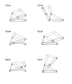
FIG. 9A is a schematic diagram showing an example of a toggle mechanism in which a relationship BD=CD is satisfied.FIG. 9B is a schematic diagram showing an example of a toggle mechanism in which a relationship BD>CD is satisfied.FIG. 9C is a schematic diagram showing an example of a toggle mechanism in which a relationship BD<CD is satisfied.FIG. 9D is a schematic diagram showing an example of a toggle mechanism in which a position of a point B lies outside an arc-shaped movement locus of a point C.FIG. 9E is a schematic diagram showing an example of a toggle mechanism in which a position of a point B lies in a position where an angle formed by a line segment AB and a line segment AC is greater than 90 degrees.FIG. 9F is a schematic diagram showing an example of a toggle mechanism in which a position of a point B lies in a position where a relationship AB>AC is satisfied. -
- 1... muffler, 5... valve device, 10... casing, 31... first chamber, 32...second chamber, 33...third chamber, 41...inlet pipe, 42...outlet pipe, 43...inner pipe, 51...stay, 52...butterfly valve, 53...first link member, 54...second link member, 55..spring, 71...first rotation axis member, 71A...first rotation axis, 72...second rotation axis member, 72A...second rotation axis, 73...third rotation axis member, 73A...third rotation axis, 74...fourth rotation axis member, 74A...fourth rotation axis, 221...communication hole, 411...through-holes, 431...opening, 531...first stopper portion, 541... second stopper portion, L1... first link line, L2... second link line
- An embodiment to which the present invention is applied is described below with reference to the drawings.
- A
muffler 1 shown inFIG. 1 forms a part of an exhaust gas flow path through which flows an exhaust gas discharged from an in-vehicle internal combustion engine (not shown). Themuffler 1 includes acasing 10, in which openings at both ends of acylindrical shell member 11 are closed by arear lid member 12 and afront lid member 13. An inside of thecasing 10 is partitioned into three chambers, i.e., afirst chamber 31, asecond chamber 32, and athird chamber 33 by afirst separator 21 and asecond separator 22. - The
first chamber 31 is provided between therear lid member 12 and thefirst separator 21. Thesecond chamber 32 is provided between thefirst separator 21 and thesecond separator 22. Thethird chamber 33 is provided between thesecond separator 22 and thefront lid member 13. Thesecond separator 22 has acommunication hole 221 provided therein that communicates thesecond chamber 32 and thethird chamber 33 with each other. - The
muffler 1 further includes aninlet pipe 41 through which the exhaust gas from the internal combustion engine is introduced. Theinlet pipe 41 is provided so as to penetrate through thefront lid member 13, thesecond separator 22, and thefirst separator 21 and to open to thefirst chamber 31 at its downstream-side end. Provided in an outer periphery of theinlet pipe 41 in thesecond chamber 32 are a plurality of through-holes 411 that communicate an internal space of theinlet pipe 41 and thesecond chamber 32 with each other. - The
muffler 1 further includes anoutlet pipe 42 to be connected to a not-shown tailpipe to discharge the exhaust gas. Theoutlet pipe 42 is provided so as to penetrate through therear lid member 12, thefirst separator 21, and thesecond separator 22 and to open to thethird chamber 33 at its upstream-side end. - The
muffler 1 further includes aninner pipe 43 to form a communicating flow path that communicates thefirst chamber 31 and thethird chamber 33 with each other. Theinner pipe 43 is provided so as to penetrate through thefirst separator 21 and thesecond separator 22, to open to thefirst chamber 31 at its upstream-side end, and to open to thethird chamber 33 at its downstream-side end. However, in thethird chamber 33, theinner pipe 43 has, at the downstream-side end thereof, avalve device 5 mounted to open and close anopening 431 provided at the downstream-side end of theinner pipe 43. - As shown in
FIGS. 2A, 2B ,3A, and 3B , thevalve device 5 includes astay 51, abutterfly valve 52, afirst link member 53, and asecond link member 54. Thestay 51 is fixed in position with respect to theopening 431 provided at the downstream-side end of theinner pipe 43. Each of thebutterfly valve 52 and thefirst link member 53 is supported at one end thereof by thestay 51. Thesecond link member 54 is supported at one end thereof by thebutterfly valve 52. - The
butterfly valve 52 is shaped so as to be able to close theopening 431 of theinner pipe 43, and is connected at an end thereof to thestay 51 via a firstrotation axis member 71. Specifically, thebutterfly valve 52 is supported by thestay 51 so as to be rotationally movable about a rotation axis (hereinafter referred to as a "first rotation axis 71A") of the firstrotation axis member 71, and opens and closes theopening 431 of theinner pipe 43 according to its rotational position. - The
first link member 53 is connected at an end thereof to thestay 51 via a secondrotation axis member 72. Specifically, thefirst link member 53 is supported by thestay 51 so as to be rotationally movable about a rotation axis (hereinafter referred to as a "second rotation axis 72A") of the secondrotation axis member 72. - The
second link member 54 is connected at an end thereof to an upper surface (a portion that stands up with valve opening) of thebutterfly valve 52 via a thirdrotation axis member 73. Specifically, thesecond link member 54 is supported by thebutterfly valve 52 so as to be rotationally movable about a rotation axis (hereinafter referred to as a "third rotation axis 73A") of the thirdrotation axis member 73. - The
first link member 53 and thesecond link member 54 are connected to each other via a fourthrotation axis member 74. Specifically, thefirst link member 53 and thesecond link member 54 are connected to each other so as to be mutually rotationally movable about a rotation axis (hereinafter referred to as a "fourth rotation axis 74A") of the fourthrotation axis member 74. Thefirst rotation axis 71 A, thesecond rotation axis 72A, thethird rotation axis 73A, and thefourth rotation axis 74A are parallel to one another in an axial direction. - Due to such a configuration, the
stay 51, thebutterfly valve 52, thefirst link member 53, and thesecond link member 54 form a toggle mechanism of a link type. Thebutterfly valve 52 is rotationally movable from a valve closed state (FIGS. 2A and 2B ) in which theopening 431 of theinner pipe 43 is closed to a valve open state (FIGS. 3A and 3B ) in which theopening 431 of theinner pipe 43 is open. - The
valve device 5 further includes aspring 55 to bias thebutterfly valve 52 in a valve closed direction. Thespring 55 is mounted to the thirdrotation axis member 73, and applies a biasing force in a direction to bring thebutterfly valve 52 and thesecond link member 54 closer to a positional relationship (angle) in a valve closed state. Accordingly, in its regular state (a state in which no external force to open thebutterfly valve 52 is applied), thebutterfly valve 52 is in a valve closed state. - The
first link member 53 and thesecond link member 54 are designed to be arranged in an approximately straight line in a valve closed state. In other words, in a plane orthogonal to thefirst rotation axis 71 A, an angle θ formed by a first link line L1 connecting thesecond rotation axis 72A (specifically, an intersection between the axis and the plane, and the same applies hereafter) and thefourth rotation axis 74A to each other and a second link line L2 connecting thethird rotation axis 73A and thefourth rotation axis 74A to each other is an angle close to 180 degrees in a valve closed state (FIGS. 2A and 2B ). It is designed so that the angle θ becomes smaller as thebutterfly valve 52 is rotationally moved in a valve open direction (FIGS. 3A and 3B ), and the angle θ in a valve closed state is formed to be the largest. Accordingly, in a valve closed state, a strong external force is required to rotationally move thebutterfly valve 52 in the valve open direction. - Further provided in the
valve device 5 is a stopper mechanism to limit the angle θ formed by the first link line L1 and the second link line L2 to an angle smaller than 180 degrees. Specifically, the stopper mechanism includes afirst stopper portion 531 provided on thefirst link member 53 and asecond stopper portion 541 provided on thesecond link member 54. The angle θ formed by the first link line L1 and the second link line L2 is limited to an angle smaller than 180 degrees by abutment of thefirst stopper portion 531 and thesecond stopper portion 541 against each other. - In the present embodiment, the
first link member 53 includesside plate portions coupling plate portion 534 coupling theside plate portions side plate portions coupling plate portion 544 coupling theside plate portions coupling plate portion 534 of thefirst link member 53 and theside plate portions coupling plate portion 534 of thefirst link member 53 functions as thefirst stopper portion 531, and theside plate portions second stopper portion 541. - Next, an explanation will be given about an action of the
valve device 5. The exhaust gas from the internal combustion engine is introduced into thesecond chamber 32 via the plurality of through-holes 411 formed in theinlet pipe 41, as indicated by arrows inFIG. 1 , and noise is silenced by an expansion effect and a resonance effect. Subsequently, the exhaust gas in thesecond chamber 32 is introduced into thethird chamber 33 via thecommunication hole 221 formed in thesecond separator 22, and noise is further silenced by an expansion effect and a resonance effect. In this way, the exhaust gas in thethird chamber 33, pressure pulsation of which has been smoothed and noise of which has been silenced, is discharged to the outside via theoutlet pipe 42. - Here, when a pressure in the
first chamber 31 is still low, e.g., when the number of revolutions of the internal combustion engine is low, a pressure difference between that in thefirst chamber 31 and that in thethird chamber 33 is small. At this time, an acting force exerted on thebutterfly valve 52 of thevalve device 5 by the pressure in thefirst chamber 31 is smaller than an acting force exerted on thebutterfly valve 52 of thevalve device 5 by a load applied by the toggle mechanism and thespring 55 in thevalve device 5 and the pressure in thethird chamber 33. Accordingly, theopening 431 of theinner pipe 43 is closed by thebutterfly valve 52. - In contrast, when operating conditions of the internal combustion engine have changed and, for example, when the number of revolutions of the internal combustion engine is increased to increase an amount of the exhaust gas and the pressure is increased to a predetermined pressure, the acting force exerted on the
butterfly valve 52 of thevalve device 5 by the pressure in thefirst chamber 31 becomes larger than the acting force exerted on thebutterfly valve 52 of thevalve device 5 by the load applied by the toggle mechanism and thespring 55 in thevalve device 5 and the pressure in thethird chamber 33. As a result, as shown inFIG. 4 , thebutterfly valve 52 is spaced apart from theopening 431 of theinner pipe 43 against the latter acting force to open theopening 431, and thefirst chamber 31 and thethird chamber 33 thereby communicate with each other via theinner pipe 43. - In this way, the
opening 431 of theinner pipe 43 is opened and a communicating flow path (a bypass flow path) is formed separately when the pressure in thefirst chamber 31 is increased to the predetermined pressure or more, and thus, even when an amount of the exhaust gas introduced into thefirst chamber 31 is increased, such exhaust gas is promptly discharged to thethird chamber 33. Consequently, the pressure in thefirst chamber 31 is not increased, and even when the pressure of the exhaust gas from the internal combustion engine is increased, an increase in back pressure thereof can be suppressed. Furthermore, even when a flow rate of the exhaust gas is increased, an increase in pressure in themuffler 1 can be suppressed and, thus, airflow noise is reduced. - As described above, in the
valve device 5 according to the present embodiment, thestay 51, thebutterfly valve 52, thefirst link member 53, and thesecond link member 54 form the toggle mechanism of a link type. Since the angle θ formed by the first link line L1 and the second link line L2 in a valve closed state is an angle close to 180 degrees, a strong external force is required to rotationally move thebutterfly valve 52 in the valve open direction. Accordingly, it is possible to make the external force required to open thebutterfly valve 52 greater, while weakening a biasing force of thespring 55, compared with a conventional configuration in which a butterfly valve is kept in a valve closed state solely by means of a spring. That is, it is possible to reduce a load to keep thebutterfly valve 52 in a valve open state, while increasing a load to bring thebutterfly valve 52 from a valve closed state to a valve open state. Consequently, it is possible to reduce pressure loss at the time of high revolution of the internal combustion engine, while reducing noise by improving air-tightness at the time of low revolution or initial explosion of the internal combustion engine. In addition, a striking noise made when thebutterfly valve 52 is closed can be reduced because the biasing force of thespring 55 can be weakened. - Specifically, as shown in
FIG. 5A , in the conventional configuration in which a butterfly valve is kept in a valve closed state solely by means of a spring, the larger a degree of opening (an opening amount) of the butterfly valve is, the larger a moment (an opening load at the time when the butterfly valve is pushed in a direction in which the exhaust gas flows) becomes (a broken line L1). In contrast, in the configuration according to the present embodiment, in which thebutterfly valve 52 is kept in a valve closed state by means of the toggle mechanism and thespring 55, a moment at the time when thebutterfly valve 52 starts opening becomes larger (a solid line L2). That is, as shown inFIG. 5B , thespring 55 has linear characteristics such that the larger the degree of opening of thebutterfly valve 52 is, the larger the moment becomes (a broken line L3), and the toggle mechanism has characteristics such that the moment becomes largest when thebutterfly valve 52 is in a valve closed state (a solid line L4). Therefore, in the configuration according to the present embodiment, in which thebutterfly valve 52 is kept in a valve closed state by means of the toggle mechanism and thespring 55, it is possible to decrease the moment in a state in which the degree of opening of thebutterfly valve 52 is larger, while increasing the moment in a state in which the degree of opening is smaller. - Since the
valve device 5 has the stopper mechanism provide therein, a problem that thebutterfly valve 52 cannot be normally opened when the angle θ formed by the first link line L1 and the second link line L2 has reached 180 degrees can be made less likely to occur. Such a stopper mechanism is especially effective to make the angle θ formed by the first link line L1 and the second link line L2 in a valve closed state closer to 180 degrees. This is because it is assumed that the closer to 180 degrees the angle θ in a valve closed state is, the more likely an actually formed angle under the influence of variations in parts dimensions, rattling of parts, or the like reaches 180 degrees. - Especially, the stopper mechanism according to the present embodiment is provided to the
first link member 53 and thesecond link member 54 themselves that form the first link line L1 and the second link line L2, respectively, and thus, it is possible to reduce the influence of factors such as variations in parts dimensions and rattling of parts on a limit angle. As a result, the angle θ in a valve closed state can be designed to be an angle closer to 180 degrees, and a configuration with high performance to keep a valve closed state against an external force can be achieved. - The
first chamber 31 corresponds to an example of an upstream chamber, and thethird chamber 33 corresponds to an example of a downstream chamber. Thevalve device 5 corresponds to an example of a valve device for an exhaust gas flow path, thestay 51 corresponds to an example of a support body, thebutterfly valve 52 corresponds to an example of a valve body, thefirst link member 53 and thesecond link member 54 correspond to an example of a first link member and a second link member, respectively, and thespring 55 corresponds to an example of a biasing member. Thefirst rotation axis 71A to thefourth rotation axis 74A correspond to an example of a first rotation axis to a fourth rotation axis, respectively, and the first link line L1 and the second link line L2 correspond to an example of a first link line and a second link line, respectively. - The embodiment of the present invention has been described hereinabove. However, it is to be appreciated that the present invention is not limited to the above-described embodiment and can take various forms.
- (1) In the above-described embodiment, as a biasing device to bias the
butterfly valve 52 in the valve closed direction, thespring 55 to apply a biasing force in a direction to bring thebutterfly valve 52 and thesecond link member 54 closer to a positional relationship (angle) in a valve closed state is exemplified. However, the biasing device is not limited to this. As shown inFIGS. 6A and 6B for example, a configuration may be adopted in which thespring 55 is mounted to the fourthrotation axis member 74 and a biasing force is applied in a direction to bring thefirst link member 53 and thesecond link member 54 closer to a positional relationship (angle) in a valve closed state. Alternatively, as shown inFIGS. 7A and 7B for example, a configuration may be adopted in which thespring 55 is mounted to the secondrotation axis member 72 and a biasing force is applied in a direction to bring thestay 51 and thefirst link member 53 closer to a positional relationship (angle) in a valve closed state. - (2) In the above-described embodiment, the stopper mechanism configured such that the
first stopper portion 531 provided on thefirst link member 53 and thesecond stopper portion 541 provided on thesecond link member 54 abut against each other is exemplified. However, the stopper mechanism is not limited to this. As shown inFIGS. 8A and 8B for example, a configuration may be adopted in which the angle θ formed by the first link line L1 and the second link line L2 is limited to an angle smaller than 180 degrees by abutment of a protruding portion 545 formed in thesecond link member 54 against the upper surface of thebutterfly valve 52. - (3) A positional relationship of the
first rotation axis 71A to thefourth rotation axis 74A with respect to one another is not limited to that exemplified in the above-described embodiment. As shown inFIGS. 9A to 9F for example, various positional relationships can be adopted. In these figures, points at the intersections of thefirst rotation axis 71A to thefourth rotation axis 74A with the plane orthogonal to these axes are referred to as A to D, respectively. In each of these figures, a valve closed state is shown with a solid line, and a valve open state is shown with a broken line.
For example, a relationship between a line segment BD (a length of the first link line L1) and a line segment CD (a length of the second link line L2) may be BD=CD as shown inFIG. 9A , may be BD>CD as shown inFIG. 9B , or may be BD<CD as shown inFIG. 9C .
As shown inFIG. 9D , a position of a point B (a position of thesecond rotation axis 72A) may lie outside an arc-shaped movement locus of a point C. As shown inFIG. 9E , a position of a point B may lie in a position where an angle formed by a line segment AB and a line segment AC is larger than 90 degrees. As shown inFIG. 9F , a position of a point B may lie in a position where a relationship AB>AC is satisfied. - (4) In the above-described embodiment, the configuration in which the
valve device 5 is mounted to theinner pipe 43 at the downstream-side end thereof is exemplified. However, a position where thevalve device 5 is mounted is not limited to this. For example, thevalve device 5 may be mounted to a through-hole provided in thesecond separator 22.
Claims (3)
- A valve device for an exhaust gas flow path, the device comprising:a support body;a valve body that is supported by the support body so as to be rotationally movable about a first rotation axis and that opens and closes a communicating flow path that communicates an upstream chamber and a downstream chamber in an exhaust gas flow path with each other;a first link member supported by the support body so as to be rotationally movable about a second rotation axis;a second link member supported by the valve body so as to be rotationally movable about a third rotation axis; anda biasing member to bias the valve body in a valve closed direction,wherein the first link member and the second link member are connected to each other so as to be mutually rotationally movable about a fourth rotation axis,wherein the first rotation axis, the second rotation axis, the third rotation axis, and the fourth rotation axis are parallel to one another in an axial direction, andwherein, in a plane orthogonal to the axes, an angle formed by a first link line connecting the second rotation axis and the fourth rotation axis to each other and a second link line connecting the third rotation axis and the fourth rotation axis to each other is formed to be the largest in a state in which the communicating flow path is closed by the valve body.
- The valve device for an exhaust gas flow path according to claim 1, wherein a stopper mechanism to limit the angle formed by the first link line and the second link line to an angle smaller than 180 degrees is provided.
- The valve device for an exhaust gas flow path according to claim 2, wherein the stopper mechanism limits the angle formed by the first link line and the second link line to an angle smaller than 180 degrees by abutment of a first stopper portion provided on the first link member and a second stopper portion provided on the second link member against each other.
Applications Claiming Priority (2)
| Application Number | Priority Date | Filing Date | Title |
|---|---|---|---|
| JP2012037552A JP6017798B2 (en) | 2012-02-23 | 2012-02-23 | Exhaust flow path valve device |
| PCT/JP2013/054152 WO2013125572A1 (en) | 2012-02-23 | 2013-02-20 | Valve device for exhaust gas flow path |
Publications (3)
| Publication Number | Publication Date |
|---|---|
| EP2818660A1 true EP2818660A1 (en) | 2014-12-31 |
| EP2818660A4 EP2818660A4 (en) | 2015-10-07 |
| EP2818660B1 EP2818660B1 (en) | 2017-03-29 |
Family
ID=49005754
Family Applications (1)
| Application Number | Title | Priority Date | Filing Date |
|---|---|---|---|
| EP13751846.0A Active EP2818660B1 (en) | 2012-02-23 | 2013-02-20 | Valve device for exhaust gas flow path |
Country Status (5)
| Country | Link |
|---|---|
| US (1) | US9447715B2 (en) |
| EP (1) | EP2818660B1 (en) |
| JP (1) | JP6017798B2 (en) |
| CN (1) | CN104246161B (en) |
| WO (1) | WO2013125572A1 (en) |
Cited By (1)
| Publication number | Priority date | Publication date | Assignee | Title |
|---|---|---|---|---|
| EP3109423A1 (en) * | 2015-06-25 | 2016-12-28 | Eberspächer Exhaust Technology GmbH & Co. KG | Exhaust gas muffler |
Families Citing this family (18)
| Publication number | Priority date | Publication date | Assignee | Title |
|---|---|---|---|---|
| JP6181564B2 (en) * | 2014-01-23 | 2017-08-16 | フタバ産業株式会社 | Exhaust flow path valve device |
| CN104847936A (en) * | 2014-02-14 | 2015-08-19 | 上海天纳克排气系统有限公司 | Control valve, motor vehicle exhaust system comprising same and motor vehicle |
| EP2988040A1 (en) * | 2014-08-20 | 2016-02-24 | JKF Industri A/S | A safety valve and a safety arrangement for a fluid piping system |
| JP6382725B2 (en) | 2015-01-08 | 2018-08-29 | フタバ産業株式会社 | Exhaust flow path valve device |
| JP6426479B2 (en) * | 2015-01-08 | 2018-11-21 | フタバ産業株式会社 | Exhaust flow path valve device |
| US9464559B2 (en) | 2015-02-04 | 2016-10-11 | Middleville Tool & Die Co. | Passive exhaust valve assembly and forming method |
| JP6483469B2 (en) * | 2015-02-20 | 2019-03-13 | フタバ産業株式会社 | Muffler |
| EP3394410B1 (en) | 2015-12-24 | 2020-07-01 | Middleville Tool&Die Co. | Passive exhaust valve with floating stop |
| WO2017122063A1 (en) * | 2016-01-15 | 2017-07-20 | Middleville Tool & Die Co. | Passive exhaust valve assembly with overlapping slip joint and method of forming and installation |
| WO2017126126A1 (en) * | 2016-01-22 | 2017-07-27 | フタバ産業株式会社 | Valve device for exhaust gas flow passage |
| WO2017126127A1 (en) * | 2016-01-22 | 2017-07-27 | フタバ産業株式会社 | Muffler |
| DE112016006437T5 (en) * | 2016-02-15 | 2018-10-31 | Futaba Industrial Co., Ltd. | Shaft sealing device |
| US9982794B2 (en) | 2016-08-05 | 2018-05-29 | Tenneco Automotive Operating Company Inc. | Passive exhaust valve with external torsion spring |
| US9982793B2 (en) * | 2016-08-05 | 2018-05-29 | Tenneco Automotive Operating Company Inc. | Passive exhaust valve with dual torsion spring |
| CN106594325B (en) * | 2017-02-06 | 2018-11-20 | 广东永泉阀门科技有限公司 | Pressure reduction type backflow preventer |
| CN106594332B (en) * | 2017-02-06 | 2018-11-20 | 广东永泉阀门科技有限公司 | The anti-down flow check valve of pressure-reducing |
| JP7059570B2 (en) * | 2017-11-09 | 2022-04-26 | スズキ株式会社 | Vehicle exhaust system |
| US10788136B1 (en) * | 2019-03-29 | 2020-09-29 | Tenneco Automotive Operating Company Inc. | Damper valve assembly |
Citations (3)
| Publication number | Priority date | Publication date | Assignee | Title |
|---|---|---|---|---|
| JPH10141040A (en) * | 1996-11-14 | 1998-05-26 | Umex:Kk | Noise eliminator for internal combustion engine |
| US5947152A (en) * | 1995-08-11 | 1999-09-07 | Grinnell Corporation | Check valve and backflow preventer |
| US6443181B1 (en) * | 2000-12-28 | 2002-09-03 | Hunter Innovations, Inc. | Backflow prevention apparatus |
Family Cites Families (15)
| Publication number | Priority date | Publication date | Assignee | Title |
|---|---|---|---|---|
| US2394471A (en) * | 1944-04-22 | 1946-02-05 | Herman L Paul | Valve |
| US3182951A (en) * | 1962-01-18 | 1965-05-11 | Kenneth L Spencer | Pivoted valve |
| US4264085A (en) * | 1979-04-20 | 1981-04-28 | Frank Volin | Wheelchair convenience attachments |
| JPS59163183A (en) * | 1983-03-03 | 1984-09-14 | 株式会社 東京タツノ | Piping device connected to underground tank |
| DE3541192C1 (en) * | 1985-11-21 | 1986-11-27 | Karl Dipl.-Ing.(FH) 4040 Neuss Weinhold | Flap valve |
| JP2586177Y2 (en) * | 1993-11-12 | 1998-12-02 | 株式会社クボタ | Flap valve |
| JPH09195749A (en) * | 1996-01-16 | 1997-07-29 | Futaba Sangyo Kk | Muffler for internal combustion engine |
| JPH10137070A (en) * | 1996-11-13 | 1998-05-26 | Ikeda Bussan Co Ltd | Footrest mechanism |
| JP4141601B2 (en) * | 1999-09-24 | 2008-08-27 | カルソニックカンセイ株式会社 | Control silencer for automobile |
| JP2002180446A (en) * | 2000-12-14 | 2002-06-26 | Kubota Corp | Flap valve |
| JP4612233B2 (en) * | 2001-06-22 | 2011-01-12 | フタバ産業株式会社 | Muffler for internal combustion engine |
| CN1991138A (en) * | 2005-12-31 | 2007-07-04 | 张庆义 | Automobile sound absorber assembly |
| CN200978702Y (en) * | 2006-11-16 | 2007-11-21 | 上海通用汽车有限公司 | Exhaust silencer of automobile |
| JP2008175113A (en) * | 2007-01-17 | 2008-07-31 | Calsonic Kansei Corp | Exhaust control valve |
| JP2008255879A (en) * | 2007-04-04 | 2008-10-23 | Nissan Motor Co Ltd | Method for controlling exhaust sound for vehicle and device for controlling exhaust sound for vehicle |
-
2012
- 2012-02-23 JP JP2012037552A patent/JP6017798B2/en active Active
-
2013
- 2013-02-20 EP EP13751846.0A patent/EP2818660B1/en active Active
- 2013-02-20 CN CN201380010358.6A patent/CN104246161B/en active Active
- 2013-02-20 US US14/380,104 patent/US9447715B2/en active Active
- 2013-02-20 WO PCT/JP2013/054152 patent/WO2013125572A1/en active Application Filing
Patent Citations (3)
| Publication number | Priority date | Publication date | Assignee | Title |
|---|---|---|---|---|
| US5947152A (en) * | 1995-08-11 | 1999-09-07 | Grinnell Corporation | Check valve and backflow preventer |
| JPH10141040A (en) * | 1996-11-14 | 1998-05-26 | Umex:Kk | Noise eliminator for internal combustion engine |
| US6443181B1 (en) * | 2000-12-28 | 2002-09-03 | Hunter Innovations, Inc. | Backflow prevention apparatus |
Non-Patent Citations (2)
| Title |
|---|
| None * |
| See also references of WO2013125572A1 * |
Cited By (2)
| Publication number | Priority date | Publication date | Assignee | Title |
|---|---|---|---|---|
| EP3109423A1 (en) * | 2015-06-25 | 2016-12-28 | Eberspächer Exhaust Technology GmbH & Co. KG | Exhaust gas muffler |
| US9759105B2 (en) | 2015-06-25 | 2017-09-12 | Eberspächer Exhaust Technology GmbH & Co. KG | Exhaust muffler |
Also Published As
| Publication number | Publication date |
|---|---|
| US20150027566A1 (en) | 2015-01-29 |
| JP6017798B2 (en) | 2016-11-02 |
| CN104246161A (en) | 2014-12-24 |
| CN104246161B (en) | 2017-05-17 |
| EP2818660B1 (en) | 2017-03-29 |
| US9447715B2 (en) | 2016-09-20 |
| WO2013125572A1 (en) | 2013-08-29 |
| JP2013174131A (en) | 2013-09-05 |
| EP2818660A4 (en) | 2015-10-07 |
Similar Documents
| Publication | Publication Date | Title |
|---|---|---|
| EP2818660A1 (en) | Valve device for exhaust gas flow path | |
| EP2024612B1 (en) | Muffler | |
| US9388719B2 (en) | Muffler | |
| JPH08189328A (en) | Butterfly valve | |
| US9695718B2 (en) | Silencer | |
| WO2015072271A1 (en) | Valve device for exhaust gas passage | |
| JP6491362B2 (en) | Muffler | |
| CN109923310B (en) | Noise silencer | |
| JP2009097376A (en) | Valve device for muffler | |
| US11661871B2 (en) | Muffler for vehicle | |
| US10934882B2 (en) | Turbocharger | |
| JP6596394B2 (en) | Silencer | |
| US10571036B2 (en) | Valve device for exhaust flow passage | |
| CN214836728U (en) | Adaptive valve assembly and internal combustion engine system | |
| CN219413629U (en) | Muffler valve | |
| JP5400682B2 (en) | Exhaust flow control valve sliding part structure | |
| JP7420547B2 (en) | exhaust pipe valve | |
| JP4361355B2 (en) | Silencer for internal combustion engine | |
| JP4935615B2 (en) | Valve unit for silencer | |
| JP4157490B2 (en) | Valve unit for silencer | |
| JP5616661B2 (en) | Exhaust flow control valve | |
| CA2937665A1 (en) | Valve device for exhaust flow passage | |
| CN115667678A (en) | Valve for muffler and muffler |
Legal Events
| Date | Code | Title | Description |
|---|---|---|---|
| PUAI | Public reference made under article 153(3) epc to a published international application that has entered the european phase |
Free format text: ORIGINAL CODE: 0009012 |
|
| 17P | Request for examination filed |
Effective date: 20140828 |
|
| AK | Designated contracting states |
Kind code of ref document: A1 Designated state(s): AL AT BE BG CH CY CZ DE DK EE ES FI FR GB GR HR HU IE IS IT LI LT LU LV MC MK MT NL NO PL PT RO RS SE SI SK SM TR |
|
| AX | Request for extension of the european patent |
Extension state: BA ME |
|
| DAX | Request for extension of the european patent (deleted) | ||
| RA4 | Supplementary search report drawn up and despatched (corrected) |
Effective date: 20150909 |
|
| RIC1 | Information provided on ipc code assigned before grant |
Ipc: F16K 15/03 20060101ALI20150903BHEP Ipc: F16K 15/02 20060101ALI20150903BHEP Ipc: F01N 13/08 20100101AFI20150903BHEP Ipc: F01N 1/16 20060101ALI20150903BHEP Ipc: F01N 1/18 20060101ALI20150903BHEP Ipc: F01N 1/08 20060101ALI20150903BHEP |
|
| GRAP | Despatch of communication of intention to grant a patent |
Free format text: ORIGINAL CODE: EPIDOSNIGR1 |
|
| RAP1 | Party data changed (applicant data changed or rights of an application transferred) |
Owner name: FUTABA INDUSTRIAL CO., LTD. |
|
| INTG | Intention to grant announced |
Effective date: 20161010 |
|
| GRAS | Grant fee paid |
Free format text: ORIGINAL CODE: EPIDOSNIGR3 |
|
| GRAA | (expected) grant |
Free format text: ORIGINAL CODE: 0009210 |
|
| RIN1 | Information on inventor provided before grant (corrected) |
Inventor name: KOBORI, KIYOMICHI |
|
| AK | Designated contracting states |
Kind code of ref document: B1 Designated state(s): AL AT BE BG CH CY CZ DE DK EE ES FI FR GB GR HR HU IE IS IT LI LT LU LV MC MK MT NL NO PL PT RO RS SE SI SK SM TR |
|
| RAP1 | Party data changed (applicant data changed or rights of an application transferred) |
Owner name: FUTABA INDUSTRIAL CO., LTD. |
|
| REG | Reference to a national code |
Ref country code: GB Ref legal event code: FG4D |
|
| REG | Reference to a national code |
Ref country code: CH Ref legal event code: EP |
|
| REG | Reference to a national code |
Ref country code: AT Ref legal event code: REF Ref document number: 880002 Country of ref document: AT Kind code of ref document: T Effective date: 20170415 |
|
| REG | Reference to a national code |
Ref country code: IE Ref legal event code: FG4D |
|
| REG | Reference to a national code |
Ref country code: DE Ref legal event code: R096 Ref document number: 602013019195 Country of ref document: DE |
|
| PG25 | Lapsed in a contracting state [announced via postgrant information from national office to epo] |
Ref country code: NO Free format text: LAPSE BECAUSE OF FAILURE TO SUBMIT A TRANSLATION OF THE DESCRIPTION OR TO PAY THE FEE WITHIN THE PRESCRIBED TIME-LIMIT Effective date: 20170629 Ref country code: LT Free format text: LAPSE BECAUSE OF FAILURE TO SUBMIT A TRANSLATION OF THE DESCRIPTION OR TO PAY THE FEE WITHIN THE PRESCRIBED TIME-LIMIT Effective date: 20170329 Ref country code: GR Free format text: LAPSE BECAUSE OF FAILURE TO SUBMIT A TRANSLATION OF THE DESCRIPTION OR TO PAY THE FEE WITHIN THE PRESCRIBED TIME-LIMIT Effective date: 20170630 Ref country code: HR Free format text: LAPSE BECAUSE OF FAILURE TO SUBMIT A TRANSLATION OF THE DESCRIPTION OR TO PAY THE FEE WITHIN THE PRESCRIBED TIME-LIMIT Effective date: 20170329 Ref country code: FI Free format text: LAPSE BECAUSE OF FAILURE TO SUBMIT A TRANSLATION OF THE DESCRIPTION OR TO PAY THE FEE WITHIN THE PRESCRIBED TIME-LIMIT Effective date: 20170329 |
|
| REG | Reference to a national code |
Ref country code: NL Ref legal event code: MP Effective date: 20170329 |
|
| REG | Reference to a national code |
Ref country code: AT Ref legal event code: MK05 Ref document number: 880002 Country of ref document: AT Kind code of ref document: T Effective date: 20170329 |
|
| PG25 | Lapsed in a contracting state [announced via postgrant information from national office to epo] |
Ref country code: SE Free format text: LAPSE BECAUSE OF FAILURE TO SUBMIT A TRANSLATION OF THE DESCRIPTION OR TO PAY THE FEE WITHIN THE PRESCRIBED TIME-LIMIT Effective date: 20170329 Ref country code: LV Free format text: LAPSE BECAUSE OF FAILURE TO SUBMIT A TRANSLATION OF THE DESCRIPTION OR TO PAY THE FEE WITHIN THE PRESCRIBED TIME-LIMIT Effective date: 20170329 Ref country code: BG Free format text: LAPSE BECAUSE OF FAILURE TO SUBMIT A TRANSLATION OF THE DESCRIPTION OR TO PAY THE FEE WITHIN THE PRESCRIBED TIME-LIMIT Effective date: 20170629 Ref country code: RS Free format text: LAPSE BECAUSE OF FAILURE TO SUBMIT A TRANSLATION OF THE DESCRIPTION OR TO PAY THE FEE WITHIN THE PRESCRIBED TIME-LIMIT Effective date: 20170329 |
|
| PG25 | Lapsed in a contracting state [announced via postgrant information from national office to epo] |
Ref country code: NL Free format text: LAPSE BECAUSE OF FAILURE TO SUBMIT A TRANSLATION OF THE DESCRIPTION OR TO PAY THE FEE WITHIN THE PRESCRIBED TIME-LIMIT Effective date: 20170329 |
|
| PG25 | Lapsed in a contracting state [announced via postgrant information from national office to epo] |
Ref country code: RO Free format text: LAPSE BECAUSE OF FAILURE TO SUBMIT A TRANSLATION OF THE DESCRIPTION OR TO PAY THE FEE WITHIN THE PRESCRIBED TIME-LIMIT Effective date: 20170329 Ref country code: SK Free format text: LAPSE BECAUSE OF FAILURE TO SUBMIT A TRANSLATION OF THE DESCRIPTION OR TO PAY THE FEE WITHIN THE PRESCRIBED TIME-LIMIT Effective date: 20170329 Ref country code: ES Free format text: LAPSE BECAUSE OF FAILURE TO SUBMIT A TRANSLATION OF THE DESCRIPTION OR TO PAY THE FEE WITHIN THE PRESCRIBED TIME-LIMIT Effective date: 20170329 Ref country code: EE Free format text: LAPSE BECAUSE OF FAILURE TO SUBMIT A TRANSLATION OF THE DESCRIPTION OR TO PAY THE FEE WITHIN THE PRESCRIBED TIME-LIMIT Effective date: 20170329 Ref country code: AT Free format text: LAPSE BECAUSE OF FAILURE TO SUBMIT A TRANSLATION OF THE DESCRIPTION OR TO PAY THE FEE WITHIN THE PRESCRIBED TIME-LIMIT Effective date: 20170329 |
|
| PG25 | Lapsed in a contracting state [announced via postgrant information from national office to epo] |
Ref country code: SM Free format text: LAPSE BECAUSE OF FAILURE TO SUBMIT A TRANSLATION OF THE DESCRIPTION OR TO PAY THE FEE WITHIN THE PRESCRIBED TIME-LIMIT Effective date: 20170329 Ref country code: PL Free format text: LAPSE BECAUSE OF FAILURE TO SUBMIT A TRANSLATION OF THE DESCRIPTION OR TO PAY THE FEE WITHIN THE PRESCRIBED TIME-LIMIT Effective date: 20170329 Ref country code: IS Free format text: LAPSE BECAUSE OF FAILURE TO SUBMIT A TRANSLATION OF THE DESCRIPTION OR TO PAY THE FEE WITHIN THE PRESCRIBED TIME-LIMIT Effective date: 20170729 Ref country code: PT Free format text: LAPSE BECAUSE OF FAILURE TO SUBMIT A TRANSLATION OF THE DESCRIPTION OR TO PAY THE FEE WITHIN THE PRESCRIBED TIME-LIMIT Effective date: 20170731 |
|
| REG | Reference to a national code |
Ref country code: DE Ref legal event code: R097 Ref document number: 602013019195 Country of ref document: DE |
|
| PG25 | Lapsed in a contracting state [announced via postgrant information from national office to epo] |
Ref country code: DK Free format text: LAPSE BECAUSE OF FAILURE TO SUBMIT A TRANSLATION OF THE DESCRIPTION OR TO PAY THE FEE WITHIN THE PRESCRIBED TIME-LIMIT Effective date: 20170329 |
|
| PLBE | No opposition filed within time limit |
Free format text: ORIGINAL CODE: 0009261 |
|
| STAA | Information on the status of an ep patent application or granted ep patent |
Free format text: STATUS: NO OPPOSITION FILED WITHIN TIME LIMIT |
|
| PG25 | Lapsed in a contracting state [announced via postgrant information from national office to epo] |
Ref country code: IT Free format text: LAPSE BECAUSE OF FAILURE TO SUBMIT A TRANSLATION OF THE DESCRIPTION OR TO PAY THE FEE WITHIN THE PRESCRIBED TIME-LIMIT Effective date: 20170329 |
|
| 26N | No opposition filed |
Effective date: 20180103 |
|
| PG25 | Lapsed in a contracting state [announced via postgrant information from national office to epo] |
Ref country code: SI Free format text: LAPSE BECAUSE OF FAILURE TO SUBMIT A TRANSLATION OF THE DESCRIPTION OR TO PAY THE FEE WITHIN THE PRESCRIBED TIME-LIMIT Effective date: 20170329 |
|
| REG | Reference to a national code |
Ref country code: CH Ref legal event code: PL |
|
| PG25 | Lapsed in a contracting state [announced via postgrant information from national office to epo] |
Ref country code: MC Free format text: LAPSE BECAUSE OF FAILURE TO SUBMIT A TRANSLATION OF THE DESCRIPTION OR TO PAY THE FEE WITHIN THE PRESCRIBED TIME-LIMIT Effective date: 20170329 |
|
| REG | Reference to a national code |
Ref country code: IE Ref legal event code: MM4A |
|
| REG | Reference to a national code |
Ref country code: BE Ref legal event code: MM Effective date: 20180228 |
|
| PG25 | Lapsed in a contracting state [announced via postgrant information from national office to epo] |
Ref country code: LI Free format text: LAPSE BECAUSE OF NON-PAYMENT OF DUE FEES Effective date: 20180228 Ref country code: LU Free format text: LAPSE BECAUSE OF NON-PAYMENT OF DUE FEES Effective date: 20180220 Ref country code: CH Free format text: LAPSE BECAUSE OF NON-PAYMENT OF DUE FEES Effective date: 20180228 |
|
| REG | Reference to a national code |
Ref country code: FR Ref legal event code: ST Effective date: 20181031 |
|
| PG25 | Lapsed in a contracting state [announced via postgrant information from national office to epo] |
Ref country code: IE Free format text: LAPSE BECAUSE OF NON-PAYMENT OF DUE FEES Effective date: 20180220 |
|
| PG25 | Lapsed in a contracting state [announced via postgrant information from national office to epo] |
Ref country code: BE Free format text: LAPSE BECAUSE OF NON-PAYMENT OF DUE FEES Effective date: 20180228 Ref country code: FR Free format text: LAPSE BECAUSE OF NON-PAYMENT OF DUE FEES Effective date: 20180228 |
|
| PG25 | Lapsed in a contracting state [announced via postgrant information from national office to epo] |
Ref country code: MT Free format text: LAPSE BECAUSE OF NON-PAYMENT OF DUE FEES Effective date: 20180220 |
|
| PG25 | Lapsed in a contracting state [announced via postgrant information from national office to epo] |
Ref country code: TR Free format text: LAPSE BECAUSE OF FAILURE TO SUBMIT A TRANSLATION OF THE DESCRIPTION OR TO PAY THE FEE WITHIN THE PRESCRIBED TIME-LIMIT Effective date: 20170329 |
|
| PG25 | Lapsed in a contracting state [announced via postgrant information from national office to epo] |
Ref country code: HU Free format text: LAPSE BECAUSE OF FAILURE TO SUBMIT A TRANSLATION OF THE DESCRIPTION OR TO PAY THE FEE WITHIN THE PRESCRIBED TIME-LIMIT; INVALID AB INITIO Effective date: 20130220 |
|
| PG25 | Lapsed in a contracting state [announced via postgrant information from national office to epo] |
Ref country code: CY Free format text: LAPSE BECAUSE OF FAILURE TO SUBMIT A TRANSLATION OF THE DESCRIPTION OR TO PAY THE FEE WITHIN THE PRESCRIBED TIME-LIMIT Effective date: 20170329 Ref country code: MK Free format text: LAPSE BECAUSE OF NON-PAYMENT OF DUE FEES Effective date: 20170329 |
|
| PG25 | Lapsed in a contracting state [announced via postgrant information from national office to epo] |
Ref country code: AL Free format text: LAPSE BECAUSE OF FAILURE TO SUBMIT A TRANSLATION OF THE DESCRIPTION OR TO PAY THE FEE WITHIN THE PRESCRIBED TIME-LIMIT Effective date: 20170329 |
|
| PGFP | Annual fee paid to national office [announced via postgrant information from national office to epo] |
Ref country code: CZ Payment date: 20230213 Year of fee payment: 11 |
|
| PGFP | Annual fee paid to national office [announced via postgrant information from national office to epo] |
Ref country code: GB Payment date: 20230221 Year of fee payment: 11 Ref country code: DE Payment date: 20220620 Year of fee payment: 11 |